Embed Size (px)
Citation preview
Chapter 8
Mechanical and Morphological Properties of Natural/Chloroprene Latex Blends Nanocomposites
Natural rubber latex (NRL), chloroprene rubber latex (CRL) and their
blend nanocomposites were prepared using layered silicates. Dispersions
of fluorohectorite (synthetic) and bentonite (natural) were mixed with
respective rubbers in the prevulcanized stage was used for the production of
nanocomposites. An amorphous grade of clay (English Indian clay) was also
mixed with the same combination of latices for comparison. The latex based
composites were characterized using X-ray diffraction (XRD), transmission
electron microscopy (TEM) and Fourier transform infrared spectroscopy
(FTIR). From the shift in wave number to the lower regions from the stretching
n(Si-O) and bending d (Si-O) vibrations of fluorohectorite and bentonite, it is
understood that layered clays are well intercalated in NR, CR and 80/20NRCR
blends. It was found that fluorohectorite and bentonite improves the mechanical
properties of NR, CR and also their blends. Addition of layered silicates also
improved the ageing resistance of the component rubbers and their blends.
This suggests that these latices and their blends are good intercalation material
for fluorohectorite and bentonite.
The results of this chapter have been submitted to RC & T, ACS Publications

Chapter 8258
8.1 Introduction
Layered silicates, being hydrophilic will undergo hydration in aqueous
solutions, resulting an increase in interlayer distance. Rubber latices being
fine dispersion of rubber particles in aqueous medium can penetrate in the
expanded (due to hydration) regions of layered silicates (gallery space),
which is considered to be an easy way of producing rubber nanocomposites.
Nanocomposites of natural rubber latex were produced both from compounded
and prevulcanization routes [1-7].
It has been found that uniform distribution of nanoscale-silicate layers
imparts better mechanical and barrier properties to NR latex film. Methods are
also reported to produce nanocomposites from solution mixing of latex and
layered silicates followed by coagulation [8]. However the slow rate of drying
of the coagulated mass and processing difficulties thereafter diminished the
production of rubber nanocomposites through this route. Due to the enhanced
modulus and reduced barrier properties, unlike the virgin rubber, nanocomposites
have got a wide spectrum of applications. Comparatively lower level of loading
and the identical colloidal properties of the latex nanocompounds with the
conventional micro-dispersions made it more acceptable to the latex dipping
industry [9].
Blending of polymers in the latex stage has provided an easy and
efficient way to produce new types of high performance materials which
results in a molecular level dispersion of materials [10-13]. The enhancement
in properties by the addition of layered silicate to latex depends on nature
of the polymer (polar or non polar), type of clay (hydrophilic or hydrophobic)

Mechanical and Morphological Properties of… 259
and it’s loading. The level of exfoliation rather than the amount of layered
silicate decides the composite properties. Blending of CR latex with NR latex
will increase the polarity of NR latex (thereby increases the compatibility with
layered silicates) which is expected to impart good mechanical properties to
the resulting nanocompounds. Hence a study was undertaken to evaluate the
composites properties of NR/CR latex blends.
8.2 Experimental
Materials and the equipment used are given in chapter 2. In this study
blending of latices and then film was casted. Latex blends (viz. 50/50 and
80/20) were prepared by blending the respective latices. Aqueous dispersions
of layered silicates were mixed with the latex blends in definite proportions. It
was then cast on raised glass plates having dimensions of 13cm x l0cm x 2mm.
The casting was allowed to dry at room temperature until transparent and post
vulcanized at 70°C for 2h in an air-circulated oven. The samples thus obtained
were kept in a desiccator for mechanical testing.
The composites are denoted as given below.
CR- Chloroprene rubber NR- prevulcanized natural rubber (with sulphur)
CRF- CR with fluorohectorite NRF- prevulcanized NR with fluorohectorite
CRE- CR with bentonite NRE- prevulcanized NR with bentonite
CRC- CR with China clay NRC- prevulcanized NR with China clay
50/50NRCR- 50:50 80/20NRCR - 80:20 prevulcanized
prevulcanized NR/CR blend NR /CR blend

Chapter 8260
8.3 Result and discussion
8.3.1 The XRD studies of NR, CR and their blends nanocompsites
The XRD spectra of the composites are given in Figure 8. 1. The XRD
method involves the monitoring of the position, shape, and intensity of the
basal reflections from the distributed platelets of layered silicates within the
polymer matrix. A shift of the characteristic diffraction peak to lower angles
suggests an increase in interlayer spacing of the clay, which is referred as
intercalation. Disappearance of this peak may indicate a possible exfoliation of
the clay platelets from stacks. Other change might be peak broadening which
is considered to be a result of certain level of intercalation and exfoliation
[14].
The spectra of pure fluorohectorite and its nanocomposites with NR, CR
and 80/20NRCR blends are shown in Figure 8.1A. Sodium fluorohectorite has two
peaks corresponding to the 2θ values 7.8° and the other at 9.23° corresponding
to the interlayer distances 1.16 and 0.95 nm respectively. The sharp peak at
9.23° suggests that bulk of the fluorohectorite has the characteristic interlayer
distance of 0.95nm.
Fluorohectorite filled NR showed a broad peak at 7.7° (d =1.17nm)
and a less broad peak at 3.4° (d= 2.6nm.) This suggests that peak at 9.23°
(fluorohectorite) has shifted to the lower angles 7.7° indicating an increase in
the interlayer distance from 0.95nm to 1.17nm. Similarly the minor peak at 7.8°
was shifted to 3.4° causing an increase in interlayer distance from 1.17 to 2.6nm
in the composite. All these suggest that NR hydrocarbon intercalated well with
fluorohectorite.

Mechanical and Morphological Properties of… 261
Inte
nsity
0 2 4 6 8 10 12 14
2 theta, degree
80/20NRCRF3nm
F, 0.95nmF, 1.16nm
NRF, 1.17nmNRF, 2.6nm
CRF, 0.94nm
80/20NRCRF1nm
CRF, 2.5nm
Figure 8.1(A) XRD spectra of fluorohectorite (10 phr) of NR, CR and 80/20NRCR blend. Spectrum of pure fluorohectorite is also given.
In the case of CR nanocomposite 2 peaks were resolved one at 9.4°
and another at 3.5° which corresponds to the d distance 0.94 nm and 2.5 nm
respectively. The peaks are less prominent compared to the NR-fluorohectorite
composite.This suggests almost complete exfoliation of fluorohectorite in CR
latex. The reason for the higher intercalation of CR with fluorohectorite might
be due to the polar nature of CR molecules. However in an 80/20 blend of NR
latex with CR latex (80/20NRCRF) two peaks were observed. The strong peak
at 2.9° (d= 3nm) and a less broad peak at 8.6° (1nm). In this case also there is a
visible shift in the peaks which suggests that the blend is good intercalating with
fluorohectorite.
Chapter 8262
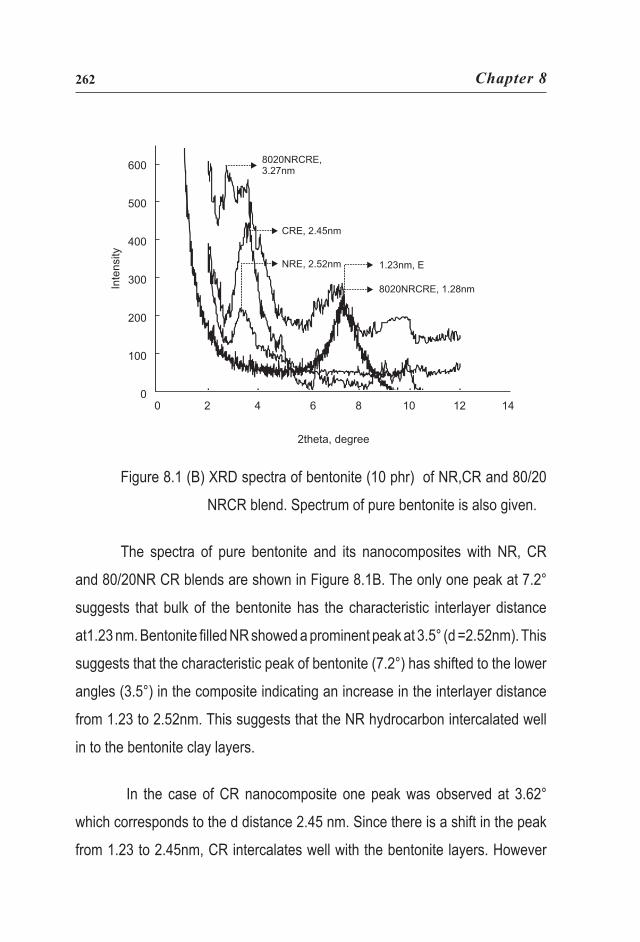
Figure 8.1 (B) XRD spectra of bentonite (10 phr) of NR,CR and 80/20
NRCR blend. Spectrum of pure bentonite is also given.
The spectra of pure bentonite and its nanocomposites with NR, CR
and 80/20NR CR blends are shown in Figure 8.1B. The only one peak at 7.2°
suggests that bulk of the bentonite has the characteristic interlayer distance
at1.23 nm. Bentonite filled NR showed a prominent peak at 3.5° (d =2.52nm). This
suggests that the characteristic peak of bentonite (7.2°) has shifted to the lower
angles (3.5°) in the composite indicating an increase in the interlayer distance
from 1.23 to 2.52nm. This suggests that the NR hydrocarbon intercalated well
in to the bentonite clay layers.
In the case of CR nanocomposite one peak was observed at 3.62°
which corresponds to the d distance 2.45 nm. Since there is a shift in the peak
from 1.23 to 2.45nm, CR intercalates well with the bentonite layers. However
Inte
nsity
600
500
400
300
200
100
00 2 4 6 8 10 12 14
2theta, degree
8020NRCRE,3.27nm
CRE, 2.45nm
NRE, 2.52nm 1.23nm, E
8020NRCRE, 1.28nm

Mechanical and Morphological Properties of… 263
in an 80/20 blend of NR latex with CR latex (80/20NRCRE) two peaks were
observed. The strong peak at 2.7° (d= 3.27nm) and a less broad peak at 6.88°
(1.28nm). In this case also there is a visible shift in the peaks suggesting that
the blend is a better intercalation material for bentonite, compared to the pure
natural rubber latex.
8.3.2 FTIR analysis of NR, CR and their blends nanocomposites.
The absorption bands in the infrared (IR) spectrum of various layered
silicates depend on their chemical composition. Differences between the FTIR
spectra of pure clay and their nanocomposites were analyzed among peaks
corresponding to the vibrations of the macromolecular chains of either CR, NR
or in their blend. The vibration of the Si-O bond in the clays was found to be
sensitive to stress (here better adhesion between rubber and silicate) indicating
a shift to lower wave numbers with increasing level of strain.
Figure 8.2(A) FTIR spectra of fluorohectorite at 10 phr loading in NR,CR and 80/20NRCR blend vulcanizates
Transm
ittance, %
140
120
100
80
60
40
20
0
Wave number, cm-1
1200 1100 1000 900 800 600 500 400
80/20NRCRF,995CRF, 985NRF, 984F, 1005
80/20NRCRF, 461CRF, 461NRF, 459F, 476

Chapter 8264
In fluorohectorite (F), the IR spectrum presents mainly two peaks
corresponding to the Si-O stretching vibration, n(Si-O) at 1005 cm-1 and the
Si-O bending vibration, d (Si-O) at 476 cm-1(Figure 8. 2A). As presented, the
Si-O stretching vibration at 1005 cm-1, in the case of CR/fluorohectorite system
is appearing at 985 cm-1 whereas, it is at 984cm-1 in NR/fluorohectorite. The
blend 80/20 NRCR with fluorohectorite showed that the peak is at 995cm-1.
The bending vibration of fluorohectorite d (Si-O) at 476 cm-1 is shifted to 461
in CR and 459 in NR and 461 in the blend nanocomposites. These changes
in the peaks to lower wave numbers indicated the higher energy required in
the stretching and bending vibrations of Si-O bond due to the intercalation with
polymer chains.
In the case of bentonite nanocomposites (Figure 8.2 B), the effect of
intercalation is very much visible in the FTIR spectra.
Tran
smittan
ce, %
120
100
80
60
40
20
01200 1100 1000 900 800 600 500 400
Wave number, cm-1
NRE, 1065
CRE, 106880/20NRCRE,1082E, 1115
NRE, 999
CRE, 99980/20NRCRE,1005E, 1035
NRE, 519
CRE, 51980/20NRCRE,525
E, 529
Figure 8. 2(B) FTIR spectra of bentonite at 10 phr loading in NR,CR and 80/20NRCR blend vulcanizates
Mechanical and Morphological Properties of… 265
The IR spectrum of bentonite (E) presents mainly two peaks, two of
them corresponding to the Si-O stretching vibrations, n (Si-O) at 1035 cm-1 and
stretching / wagging w (Si-O) at 1115 cm-1. Here 1035 cm-1 band corresponds
to the in-plane stretching (n) and 1115 cm-1 band corresponds to out-of plane
stretching/wagging vibrations (w). The Si-O bending vibration of bentonite,
d (Si-O) is at 529 cm-1. Sensitivity of these peaks to intercalation/ exfoliation
phenomena is discussed here. As presented in Figure, the in-plane Si-O
stretching vibration (d) of pure bentonite clay at the 1035 cm-1 is appearing
at 999 cm-1 in the case of both CR/bentonite and NR/bentonite systems . The
blend, 80/20 NRCR with bentonite showed n (Si-O) at 1005 cm-1. The out-
of plane stretching vibration band (w) of (Si-O), at 1115 cm-1 of bentonite is
shifted to 1065 cm-1 in NR/bentonite, 1068 cm-1 in CR/bentonite and 1082 cm-1
in 80/20NRCR blend bentonite system. The bending vibration of bentonite d
(Si-O) at 529 cm-1 is shifted to 519 in both CR and NR and 525 in 80/20NRCR
blend [Figure 8.2(B)] [15]. The visible shift to lower wave number regions in all
these cases explains the intercalation of polymer with silicate layers.
8.3.3 Swelling studies of NR, CR and their blends nanocomposites
The swelling curves of the composite were given in Figures 8.3. As the
equilibrium swelling (Qa) values are smaller, higher will be the 1/Qa values,
which indirectly show the crosslink density of the polymer

Chapter 8266
Figure 8. 3 1/Q values of latex vulcanizates of NR, CR and 80/20NRCR blends nanocomposites
In the case of nanocomposites the intake of solvent is lower compared
to gum compounds (Figure 8. 4). This was expected, since there was less
restriction for the solvent penetration in gum vulcanizate. At equal volume
loading of filler, the amount of solvent absorbed at equilibrium swelling is less
for the composites containing layered silicates - especially with fluorohectorite
- compared to that containing commercial clay. During swelling the solvent can
enter in the polymer along or transverse direction to the aligned silicate platelets.
The presence of impermeable clay layers decreases the solvent migration by
increasing the average diffusion path length in the specimen [16]. In commercial
clay filled rubber, the solvent uptake is restricted to a lower extent because of
the weak interface and also due to poor clay dispersion.

Mechanical and Morphological Properties of… 267
Crosslinkdensityx10
525
20
15
10
5
0
NR CR 80/20 NRCR
Gum English Indian clay Bentonite Fluorohectorite
Figure 8. 4 Crosslink density values of NR, CR and 80/20NRCR blend
nanocomposites
In well-oriented composites, the penetration perpendicular to the
orientation of clay platelets is highly restricted.
A strong polymer- filler interaction reduces the voids at the interface
which in turn, leads to less solvent pockets. An enhancement of 1/Qa values
may be due to the combined effects of reinforcement, additional crosslinking
in presence of filler and the decrease in polymer fraction in the composites.
Equilibrium swelling in solvents can be taken as a means to evaluate rubber-
filler adhesion, because filler if bonded is supposed to restrict the swelling of
the elastomers. Generally in blend system, uneven distribution of crosslinks
can be observed due to the difference in affinity of the two phases [17]. When
the nanoclays are mixed with the rubber blend, swelling decreases due to the

Chapter 8268
delaminated clay platelets. In the case of amorphous clay there is only marginal
increase in crosslink density due to the uneven distribution of filler particles. In
all these cases crosslink density is higher in layered silicate nanocomposites
compared to the amorphous clay.
8.3.4 NR and CR nanocomposites
The tensile strength of NR and CR loaded with 10 phr of fluorohectorite
and bentonite are shown in Figure 8. 5.
As NR is a strain crystallizing rubber addition of layered silicates does
not make any difference in the tensile values of the nanocomposites. However
in the case of CR, tensile strength increased from 13 to 18 MPa on addition of
10 phr fluorohectorite. This increase in tensile strength of CR may be because
of the reinforcing action of clay platelets in polychloroprene rubber. In NR and
CR, bentonite nanocomposites showed maximum properties compared to the
amorphous clay. This might be due to the high interlayer distance (1.25nm) of
bentonite and better intercalation of the rubber. Amorphous clay (English Indian
clay) imparts lower properties in both NR and CR due to the larger particle
size.
The moduli at different elongations of the composites are given in
Figures 8.6a & 6b. Unloaded NR shows very low modulus at all elongations.
It is to be noted that the addition of fluorohectorite causes sharp increase in
modulus. Bentonite also showed the same trend. However, unfilled and English
Indian clay filled material showed minimum change in modulus. In CR, (Figure
8. 6 b) the unfilled and the English Indian clay composites showed almost similar
pattern with modulus.

Mechanical and Morphological Properties of… 269
Figure 8.5 Tensile strength values of NR and CR with different silicates nanocomposites at 10 phr loading.
25
20
15
10
5
0
Gum Fluorohectorite Bentonite English Indian clay
NR CR
Tensilestrength, MPa
Figure 8.6 Modulus at various elongations of a) NR nanocomposites b)CR nanocomposites at 10 phr of silicates loading.
The corresponding CR nanocomposite (CRE and CRF) showed sharp
increase in modulus at all elongation. However, compared to NR nanocomposites
(NRF and NRE) the magnitude of the modulus values is less.
Mod
ulus, M
Pa
20
16
12
8
4
0
Elongation, %
100 300 500 100 300 500
Elongation, %
76543210
NR NRF NRE NRC C C CRE CRCR RF
(a) (b)
Chapter 8270
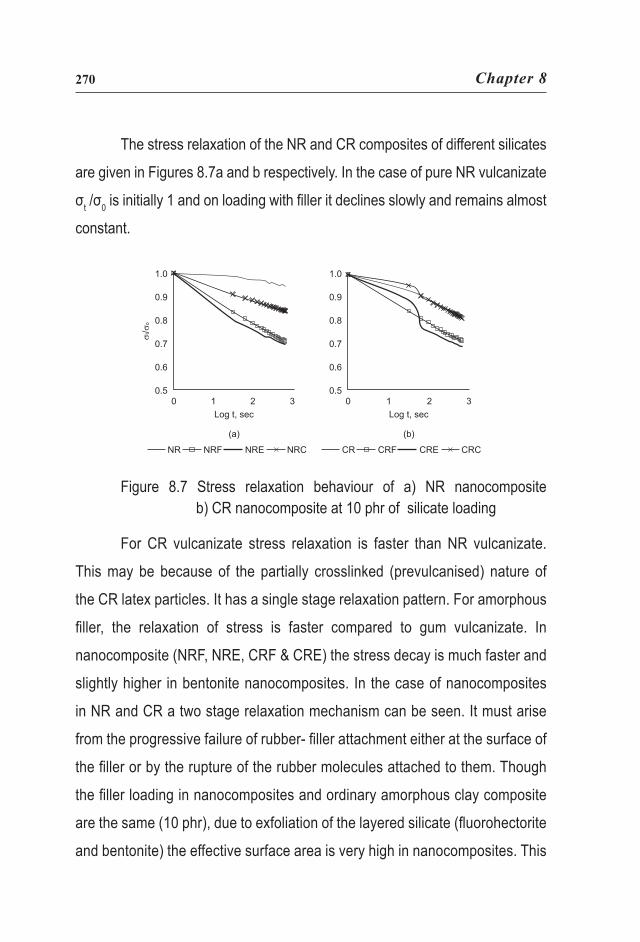
The stress relaxation of the NR and CR composites of different silicates
are given in Figures 8.7a and b respectively. In the case of pure NR vulcanizate
σt /σ0 is initially 1 and on loading with filler it declines slowly and remains almost
constant.
Figure 8.7 Stress relaxation behaviour of a) NR nanocomposite b) CR nanocomposite at 10 phr of silicate loading
For CR vulcanizate stress relaxation is faster than NR vulcanizate.
This may be because of the partially crosslinked (prevulcanised) nature of
the CR latex particles. It has a single stage relaxation pattern. For amorphous
filler, the relaxation of stress is faster compared to gum vulcanizate. In
nanocomposite (NRF, NRE, CRF & CRE) the stress decay is much faster and
slightly higher in bentonite nanocomposites. In the case of nanocomposites
in NR and CR a two stage relaxation mechanism can be seen. It must arise
from the progressive failure of rubber- filler attachment either at the surface of
the filler or by the rupture of the rubber molecules attached to them. Though
the filler loading in nanocomposites and ordinary amorphous clay composite
are the same (10 phr), due to exfoliation of the layered silicate (fluorohectorite
and bentonite) the effective surface area is very high in nanocomposites. This

Mechanical and Morphological Properties of… 271
might be the reason for the faster relaxation of stress in both NR and CR
nanocomposites.
Effect of layered silicates on tension set and tear strength in NR and CR
are given in Table 8.1.
Table 8.1 Tear strength and tension set of blends
Sample Tear strength (N/mm) Tension set ( % )
NR 47.98 1
NRF 28.9 6.67
NRE 23.2 12
NRC 41 6
CR 14.4 8
CRF 25.7 18
CRE 19.4 15.2
CRC 4 10
50/50NRCR 25.4 2
50/50NRCR F 30 14
50/50NRCR E 31.7 26
50/50NRCR C 26.1 4
80/20 NRCR 44.8 2
80/20 NRCR F 35.6 6
80/20 NRCR E 46 24
80/20 NRCR C 33.7 4
Chapter 8272
In all the cases the layered silicate has high tension set. As the filler
rubber interphase increases the chain slippage will be high. This loosely bound
interface is responsible for the high tension set in nanocomposites. Tension set
values are inversely proportional to 1/Q.
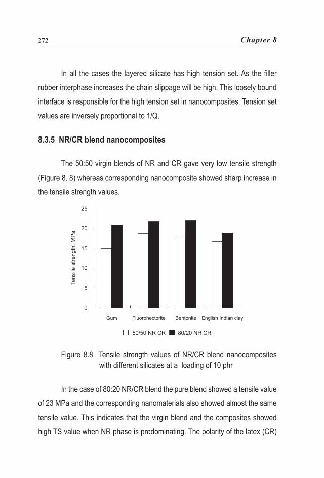
8.3.5 NR/CR blend nanocomposites
The 50:50 virgin blends of NR and CR gave very low tensile strength
(Figure 8. 8) whereas corresponding nanocomposite showed sharp increase in
the tensile strength values.
Gum Fluorohectorite Bentonite English Indian clay
50/50 NR CR 80/20 NR CR
25
20
15
10
5
0
Tensile
strength, M
Pa
Figure 8.8 Tensile strength values of NR/CR blend nanocomposites with different silicates at a loading of 10 phr
In the case of 80:20 NR/CR blend the pure blend showed a tensile value
of 23 MPa and the corresponding nanomaterials also showed almost the same
tensile value. This indicates that the virgin blend and the composites showed
high TS value when NR phase is predominating. The polarity of the latex (CR)

Mechanical and Morphological Properties of… 273
seems to be influenced by the composite properties. However the effect cannot
be assessed in blends as the strain crystallizing effect also comes to effect.
Figure 8.9 Modulus at different elongations of NR/CR blend nanocomposites at 10phr loading
Figure 8.9 shows the modulus at different elongations of the 80/20NRCR
blends. The high modulus of the fluorohectorite composite was resulted from
the high in- plane strength and large aspect ratio of the fluorohectorite clay
platelets.
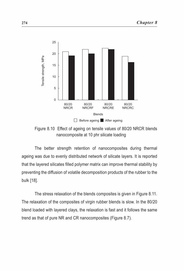
Figure 8.10 shows the comparative analysis of the after ageing tensile
strength values of 50:50 and 80:20 NR, CR blends containing 10 phr of layered
and amorphous silicates. The layered silicates nanocomposites show high
ageing resistance. This might be due to the higher crosslink formation at the
elevated temperature. After 24h of thermal ageing significant reduction in tensile
strength was noted for English Indian clay loaded composites, whereas the
reduction is comparatively less in nanocomposites.
Mod
ulus
, MPa
100 300 500
80/20 NRCR 80/20 NRCRF80/20 NRCRE 80/20 NRCRC
Elongation, %
12
10
8
6
4
2
0
Chapter 8274
Figure 8.10 Effect of ageing on tensile values of 80/20 NRCR blends nanocomposite at 10 phr silicate loading
The better strength retention of nanocomposites during thermal
ageing was due to evenly distributed network of silicate layers. It is reported
that the layered silicates filled polymer matrix can improve thermal stability by
preventing the diffusion of volatile decomposition products of the rubber to the
bulk [18].
The stress relaxation of the blends composites is given in Figure 8.11.
The relaxation of the composites of virgin rubber blends is slow. In the 80/20
blend loaded with layered clays, the relaxation is fast and it follows the same
trend as that of pure NR and CR nanocomposites (Figure 8.7).
25
20
15
10
5
0
Tens
ilest
reng
th, M
Pa
Blends
80/20NRCR
80/20NRCRF
80/20NRCRE
80/20NRCRC
Before ageing After ageing

Mechanical and Morphological Properties of… 275
Figure 8.11 Stress relaxation pattern of 80/20 NRCR blends nanocomposite at 10 phr silicate loading
8.4 Conclusion
As observed from the shifting of peaks from higher to lower 2θ values in
XRD spectra and also from higher to lower wave numbers in FTIR spectra, it is
concluded that layered silicates delaminate in NR, CR and its blends. It was also
observed that, the performance of a layered silicate in polymer depends on the
nature of the polymer and also on the interlayer distance of the clay. The tensile
strength of NR and CR and their blends loaded with 10 phr of layered silicates
showed superior TS value when NR is a major component. The nanofillers are
polar hence it is more compatibile with CR and 50:50 NR CR blends than pure

Chapter 8276
NR and 80/20NRCR blend. In blend latices, layered silicates show low elongation
values than their corresponding gum and amorphous clay vulcanizates. The
layered silicates show high ageing resistance due to the silicate platelets
distributed in the matrix. The relaxation of the composites of virgin rubbers and
their blends are slower than their corresponding nanocomposites. In all cases
the solvent swelling of nanocomposites is lower than the virgin compounds,
since there was restriction for the solvent absorption in nanocomposites. As
the amount of NR in the blend increases, tear strength values increases. In all
cases, crosslink density is higher in layered silicate nanocomposite than the
amorphous clay composites.
8.5 References
1. G. C. Psarras, K. G. Gatos, J. Karger-Kocsis, J. Appl. Polym. Sci., 106,
2, 1405 - 1411, 2007
2. Y. Wang, H. Zhang, Y. WU, J. Yang, L. Zhang, J. Appl. Polym. Sci., 96,
318 - 323, 2005
3. E. P. Giannelis, Adv. Mater., 8, 29 - 35, 1996
4. T. Pojanavaraphan, R. Magaraphan, Euro. Polym. J., 44, 7, 1968 - 1977,
2008
5. S. Mathew, S. Varghese, J. Rubb. Res., 8, 1, 1 - 15, 2005
6. R. Stephen, S. Varghese, K. Joseph, Z. Oommen, S. Thomas, J.
Membrane Sci., 282, 162 - 170, 2006
7. Z. Gu, G. Song, W. Liu, P. Li, L. Gao, H. Li, X. Hu, Appl. Clay Sci., 46 ,3
241 - 244, 2009
8. J. Karger-Kocsis, C. M. Wu, Polym. Eng. Sci., 44, 1083 - 1093, 2004

Mechanical and Morphological Properties of… 277
9. S. Mathew, S. Varghese, G. Rajammal, P. C. Thomas, J. Appl. Polym.
Sci., 104, 1, 58 - 65, 2007
10. S. Varghese, J. Karger-Kocsis, Polymer, 44, 4921 - 4927, 2003
11. J. T. Varkey, P. R. Chatterji, S. S. Rao, S. Thomas, J. Appl. Polym. Sci.,
68, 1473 - 1483,1998
12. Japan Synthetic Rubber Ltd., Brit. Pat., 1, 046, 215, 1966
13. R. Stephen, K. V. S. N. Raju, M. Rao, B. Francis, K. Joseph, S.Thomas.,
J. Appl. Polym. Sci., 104, 2528 - 2535, 2007
14. M. Yoonessi, H. Toghiani, W. L. Kingery, C. U. Pittman, Jr.,
Macromolecules, 37, 2511-2518, 2004
15. H. A. Patel, R. S. Somani, H.C. Bajaj, R.V. Jasra, Res. Commun. Curr.
Sci., 92, 7, 1004- 1009, 2007
16. Y. Kojima, K. Fukumori, A. Usuki, A. Okada, T. Kurauchi, J. Mater. Sci.
Letters, 12, 889 - 890, 1993
17. L.E. Nielsen, R.F. Landel, Mechanical properties of polymers and
composites, 2nd Edition, Marcel Dekker, New York, USA, 1994
18. Z. K. Zhu, Y. Yang, J. Yin, X. Y. Wang, Y. C. Ke, Z. N. Qi, J. Appl. Polym.
Sci., 73, 2063 - 2068, 1999