Embed Size (px)
Citation preview

Mechanical behaviour of wood in the orthotropic directions
J. L. Morais1, J. C. Xavier1, N. M. Dourado1, J. L. Lousada2
1 Departamento de Engenharias, ICETA/UTAD, Portugal
2 Departamento de Florestal, ICETA/UTAD, Portugal Abstract A numerical and experimental work was performed to examine the suitability of several specimen configurations (straight-sided, dog-bone and notched) for the determination of the tensile strength of clear Pinus Pinaster wood, in the orthotropic directions. A 3-D linear finite element model of the specimens was used to assess the uniformity and purity of stress and strain fields in their gauge section. It was found that the straight-sided and dog-bone specimens are reliable geometries for characterizing the initial linear elastic response. However, the results predicted by the finite element method using the Tsai-Hill failure criterion and the experimental observations, clearly indicate that failure is due to stress concentration effects and occurs under a complex stress state. 1 Introduction A fundamental requirement for effective utilisation of wood as a competitive structural material is the accurate knowledge of its mechanical properties. However, the experimental identification and the analytical modelling of mechanical behaviour of wood remains an open problem, due to its natural variability, inhomogeneity and anisotropy. Wood as long been recognised as an orthotropic material [1], with an internal structure which is characterised by the existence of three mutually perpendicular planes of symmetry. Those planes are defined by the longitudinal direction (L) along the fibres, the radial direction (R) towards annual rings and tangential direction (T) to the annual rings. To fully characterize the mechanical behaviour of wood it is necessary to know the stress-strain relationships referred to the LRT reference frame. The mechanical tests are the only way to obtain such data, but several difficulties arise in making the right experimental measurement, particularly those concerning the identification of ultimate stresses. In the framework of synthetic composites an intensive research effort has been devoted to the experimental identification of stress-strain relationships, including the ultimate stresses [2-8]. The same does not hold for solid wood, for which there are few studies about its orthotropic mechanical behaviour [9-14]. The majority of published works devoted to this subject focused on the initial elastic behaviour. Indeed, the structural computations are in general built in the hypothesis of a wood linear elastic behaviour [15-17]. However, it is clear from the results published by several authors that wood possesses a non-linear mechanical behaviour [18]. Hence, a more realistic

representation of mechanical behaviour of wood is needed for some structural problems, like those in the mechanics of timber joints [18]. The main problem to overcome concerning the experimental identification of complete stress-strain relationships of solid wood, in its principal material axes (L, R and T axes), is the determination of the true ultimate stresses. This is not a trivial task owing to the orthotropic nature of wood. The current standards are unsatisfactory to determine the true strengths of wood, namely the shear strengths and the strength perpendicular to the grain [14-19]. To achieve the most suitable test methods more detailed investigations must be performed about the influence of specimen geometry, size effects, loading mode and gripping arrangements. The objective of this work is to evaluate the most accurate mechanical tests for the experimental identification of on-axis tensile strength of clear wood. This is a part of a more broad investigation recently undertaken by the authors, about the non-linear mechanical behaviour of wood. 2 Experimental work Logs from Pinus Pinaster wood were live-sawn into boards, from which matched samples of mature wood were cut. Several specimens were prepared to be loaded in the L, R and T directions. Three types of specimen geometries were examined: straight-sided, dog-bone and notched specimens. Figures 1 to 3 shows these specimens configurations and the corresponding nominal dimensions. The specimen ends were reinforced with fibreboard tabs, in order to prevent any damage introduced by the loading fixture. All the specimens were tested in the green state, immediately after cutting.
3015
3
L
R
T
L
3
7
200
40 30 11 39
R16
Figure 1. Geometry and dimensions of longitudinal specimen

140
T
L
153 3
L
R 30
40
(a)
40 9.4 41.2
140
T
L
30
153 3
R5
L
R
3224
(b)
40
T
L
15.6 28.8
140
153 3
L
R
R28
22 30
(c)
Figure 2 a, b, c. Configurations of radial specimens
(a) straight-sided specimen (b) dog-bone specimen (c) notched specimen
200
T
L
40
40 153 3
L
R
Figure 3. Geometry and dimensions of tangential specimen

Quasi-static tensile tests were conducted in an Instron 1125 universal testing machine, under a crosshead speed of min/ 1mm . Wedge action grips were employed, which prevent the rotation of the specimen ends. One of the grips remains fixed while the other is displaced at a constant speed ( )min/ 1mm until specimen failure. All the tests were performed in the laboratory temperature and moisture conditions. 3 Finite element analysis The numerical modelation of uniaxial tensile tests has been achieved by the finite element method, using the commercial software ANSYS 5.6.2. A 3-D linear elastic analysis was performed based on the SOLID 45 element, from the ANSYS finite element library [20]. This element is defined by eight nodes and orthotropic directions, with a total 24 degree of freedom. The specimen geometries considered in the finite element analysis were the dog-bone and notched geometries (see Figs. 1 to 3). The finite element mesh generated to model such specimens has a number of elements between 1200 and 648. A more refined mesh does not significantly alter the results obtained. Fig. 4 illustrates the boundary conditions applied to the model, which are intended to be in agreement with the non-rigid and non-rotating gripping arrangement. On one side of the specimens, the nodes along one of the specimen edge were fixed, while a longitudinal displacement was imposed on the other side. The prescribed nodal displacements allow the free contraction in the thickness direction due to Poisson effect. Although these are idealized boundary conditions, a comparison of numerical and experimental results can be made. A plot of the deformed model was used to check the boundary conditions of the elements. In the finite element analysis described above the material properties are those corresponding to the Pine Loblolly wood [21], which are presented in Tab. 1.
Figure 4. Boundary conditions for the longitudinal specimen
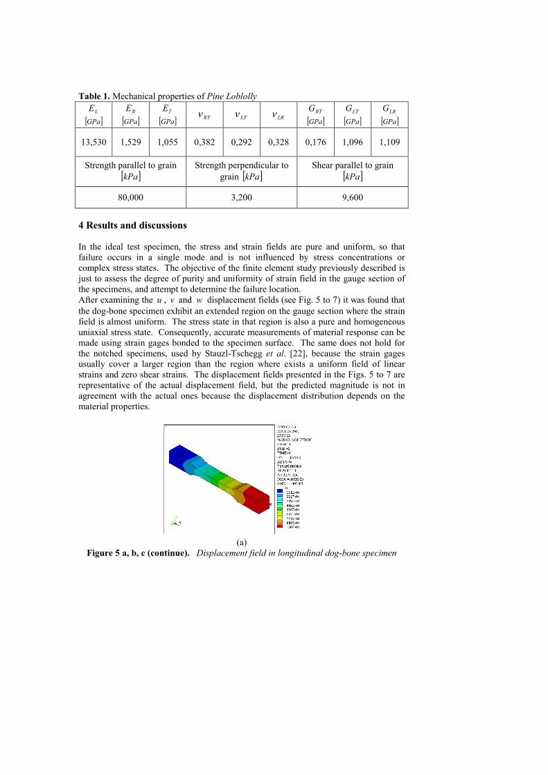
Table 1. Mechanical properties of Pine Loblolly LE
[ ]GPa RE
[ ]GPa TE
[ ]GPa RTν LTν LRν RTG [ ]GPa
LTG [ ]GPa
LRG [ ]GPa
13,530 1,529 1,055 0,382 0,292 0,328 0,176 1,096 1,109
Strength parallel to grain [ ]kPa
Strength perpendicular to grain [ ]kPa
Shear parallel to grain [ ]kPa
80,000 3,200 9,600
4 Results and discussions In the ideal test specimen, the stress and strain fields are pure and uniform, so that failure occurs in a single mode and is not influenced by stress concentrations or complex stress states. The objective of the finite element study previously described is just to assess the degree of purity and uniformity of strain field in the gauge section of the specimens, and attempt to determine the failure location. After examining the u , v and w displacement fields (see Fig. 5 to 7) it was found that the dog-bone specimen exhibit an extended region on the gauge section where the strain field is almost uniform. The stress state in that region is also a pure and homogeneous uniaxial stress state. Consequently, accurate measurements of material response can be made using strain gages bonded to the specimen surface. The same does not hold for the notched specimens, used by Stauzl-Tschegg et al. [22], because the strain gages usually cover a larger region than the region where exists a uniform field of linear strains and zero shear strains. The displacement fields presented in the Figs. 5 to 7 are representative of the actual displacement field, but the predicted magnitude is not in agreement with the actual ones because the displacement distribution depends on the material properties.
(a)
Figure 5 a, b, c (continue). Displacement field in longitudinal dog-bone specimen

(b)
(c)
Figure 5 a, b, c (continue). Displacement field in longitudinal dog-bone specimen
(a) u displacement component (b) v displacement component (c) w displacement component
(a)
Figure 6 a, b, c (continue). Displacement field in Radial dog-bone specimen

(b)
(c)
Figure 6 a, b, c (continue). Displacement field in Radial dog-bone specimen
(a) u displacement component (b) v displacement component (c) w displacement component
(a)
Figure 7 a, b, c (continue). Displacement field in Radial notched specimen

(b)
(c)
Figure 7 a, b, c (continue). Displacement field in Radial notched specimen (a) u displacement component (b) v displacement component (c) w displacement component
Since linear elastic behaviour is assumed, the location of initial failure can be calculated by comparing the element stresses with the clear wood strength via the failure criteria. In this work the Tsai-Hill criterion [23] was used, which accounts for differences in strengths in principal material directions. The finite element results depicted in Figs. 7 a, b, c suggest that the specimen geometries examined (see Figs. 1 to 3) are not appropriate to identity the true strengths of wood parallel to the grain and perpendicular to the grain. The macrofractography of the tangential specimens (see Fig. 8) demonstrates that the straight-sided geometry work very well, because the failure occurs in the gauge section away from the gripping ends. Additionally, it can be seen that the fracture surface is not oriented in the loading direction but is always fairly oriented in the tangential direction. This fact is a clear indication of a mixed mode failure, hence the recorded tensile strength (see Tab. 2) is not the true tensile strength of wood in the tangential direction. The types of failure in the Radial specimens are shown in Fig. 9. In all the tested geometries stress concentration effects influence the failure, except for the dog-bone configuration. Although the finite element analysis predicts the failure occurrence in the notch root of dog-bone specimens, most of them failed in the gauge section, probably due to the spatial distribution of wood defects. However the measured strength in the radial direction (see Tab. 2) must be used with caution.

(a)
(b)
(c)
Figure 7 a, b, c. Tsai-Hill equivalent stress, normalized by its maximum value
(a) longitudinal specimen (b) radial dog-bone specimen (c) radial notched specimen
As illustrated in Fig. 10 the failure in the longitudinal specimens occurs in the notch root as was predicted by the Tsai-Hill criteria, so that the measured strength parallel to the grain (see Tab. 2) is below the true strength.

Table 2. Tensile strength of Pinus Pinaster
Specimen Tensile Strength [ ]KPa
Tensile straight sided (see Fig. 8 a) 967
Tensile straight sided (see Fig. 8 b) 2550
Radial straight sided (see Fig. 9 a) 7778
Radial dog-bone (see Fig. 9 b) 6514
Radial dog-bone (see Fig. 9c) 7667
Radial notched (see Fig. 9d) 7089
Longitudinal straight sided (see Fig. 10) 26378
Figure 8 a, b. General appearance of failure in the tangential specimens (a) straight sided specimen (b) straight sided specimen
(a) (b)

Figure 9 a, b, c, d. Typical failure of Radial specimens (a) straight sided specimen (b) dog-bone specimen (c) dog-bone specimen (d) notched specimen
Figure 10. Typical failure of longitudinal specimen 5 Conclusions A numerical and experimental investigation has been carried out to evaluate the performance of different specimen configurations for the determination of on-axis mechanical behaviour of wood. Three types of specimen geometries were examined: straight-sided geometry, dog-bone geometry and notched geometry. The straight-sided specimen and the dog-bone specimen are suitable for experimental identification of the initial linear mechanical response, as was confirmed by a 3-D finite element analysis. However, none of the tested specimens are appropriate to measure the tensile strengths of wood in its principal material direction. The predicted and observed failure is
(a) (b) (c) (d)

influenced by stress concentration effects and occur under combined rather than pure uniaxial tensile loading. 7 References 1. Schniewird, A. P. and Barret, J. D. (1972): Wood as a linear orthotropic viscoelastic material. Wood Sci. Techn.,6(1): 43-57 2. Chamis, C. C. And Brinson, J. H. (1977): Ten-deg off-axis test for shear properties in fiber composites. Exp. Mech., September: 339-346 3. Voloshin, A. and Arcan, M. (1980): Failure of unidirectional fiber-reinforced materials – new methodology and results. Exp. Mech., August: 280-284 4. Walrath, D. E. and Adams, D. F. (1983): The Iosipescu shear test as applied to composite materials. Exp. Mech., March: 105-110 5. Sims, G. D. (1992): Development in harmonisation of standards for polymer matrix composites. Composites Testing and Standardisation, Hoggs, P. J. et al. (eds.), ECCM-CTS, EACM, September: 3-20 6. Hojo, M., Sawada, Y. And Miyairi, H. (1994): Influence of clamping method on tensile properties of unidirectional CFRP in 0º and 90º directions – round robin activity for international standardisation in Japan. Composites, 25 (8): 786-796 7. Hung, S.-C. and Liechti, K. M. (1999): Finite element analysis of the Arcan specimen for fiber reinforced composites under pure shear and biaxial loading. J. Comp. Mat., 33 (14): 1288-1317 8. Odegard, G. and Kumosa, M. (1999): Elasto-plastic analisys of the Iosipescu shear test. J. Comp. Mat., 33 (21): 1981-2001. 9. Liu, J. Y. (1984): New shear strenght test for solid wood. Wood and Fiber Science, 16 (4): 567-574 10. Sliver, A. and Yu, Y. (1993): Elastic constants for hardwood measured from plate and tension tests. Wood and Fiber Science, 25 (1): 8-12 11. Sliker, A., Ying, Y. Timothy, W. and Wenjie, Z. (1994): Orthotropic elastic constants for eastern hardwood species. Wood and Fiber Science, 26 (1): 107-121 12. Oudjehane, A. and Raclin, J. (1995): On the influence of orientation upon the mechanical behaviour of oak wood in a general state of stress. Wood Sci Techn., 29 (1): 1-10 13. Liu, J. Y., Ross, R. J. And Rammer, S. R. (1996): Improved Arcan shear test for wood. Proc. of the International Wood Engineering Conference, Gopu and Vijaya, K. A. (eds.), New Orleans, 2, 85-90 14. Liu, J. Y. (2000): Effects of shear coupling on shear properties of wood. Wood and Fiber Science, 32 (4): 458-465 15. Cheung, C. K. and Sorensen, H. C. (1983): Effect of axial loads on radial stress in curved beams. Wood and Fiber Science, 15 (3): 263-275 16. Zalpeh, B. L. and McLain, T. E. (1992): Strength of wood beams with fillet interior notches: a new model. Wood and Fiber Science, 24 (2): 204-215 17. Pellicane, P. J. and France, N. (1994): Modeling wood pole failure. Part 1: finite element stress analysis. Wood Sci Techn., 28 (3): 219-228

18. Bouchair, A. and Vergne, A. (1995): An application of Tsai criterion as a plastic flow law for Timber bolted modelling. Wood Sci Techn., 30 (1): 3-19 19. Booth, L. G. (1991): Strength of timber in tension perpendicular to the grain: UK procedures past, present and future J. Inst. Wood Sci., 12 (3): 131-142 20. Wood Handbook, (1999) Gen. Tech. Rep. FPL-GTR-113, U.S. Department of Agriculture, Forest Service, Forest Products Laboratory, 463 p. 21. Stanzl-Tschegg, S. E., Tan, D. M. and Tschegg, E. K., (1995): New splitting method for wood fracture characterization. Wood Sci Techn., 29 (1): 31-50 23. Azzi, V. D. And Tsai, S. W. (1995): Anisotropic Strength of composites. Exp. Mech., 5 (9): 283-288 Acknowledgements We would like to thanks to the Foundation for Science and Technology from the Ministry of Science and Technology for the financial support in the execution of this work, in the ambit of the project POCTI/1999/EME/36270, “Non-linear mechanical behaviour of wood”.