Embed Size (px)
Citation preview
19 September, 2005 The University of Adelaide Copyright © 2005 Slide Number 1
Mechanical Department RoboCup
David JacksonNathan Simmonds
Robert StewartSupervisor: Dr. Frank Wornle
19 September, 2005 The University of Adelaide Copyright © 2005 Slide Number 2
Mechanical Department RoboCup
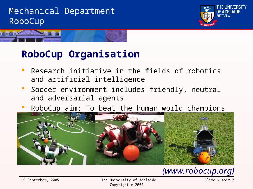
RoboCup Organisation
Research initiative in the fields of robotics and artificial intelligence Soccer environment includes friendly, neutral and adversarial agents RoboCup aim: To beat the human world champions by 2050
(www.robocup.org)

19 September, 2005 The University of Adelaide Copyright © 2005 Slide Number 3
Mechanical Department RoboCup
Project Aim
To develop skills such as ball collection, obstacle avoidance and kicking
Intelligence SystemDecision making algorithmsPath Planning
Vision Processing
Camera Motors
Controller
KickerCamera
19 September, 2005 The University of Adelaide Copyright © 2005 Slide Number 4
Mechanical Department RoboCup
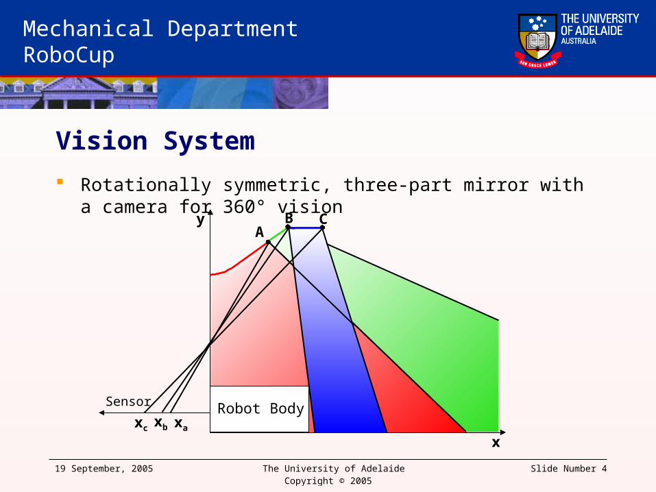
A
xa
Robot Body
B
xb
Vision System
Rotationally symmetric, three-part mirror with a camera for 360° vision
x
Sensor
y
Robot Body
C
xc

19 September, 2005 The University of Adelaide Copyright © 2005 Slide Number 5
Mechanical Department RoboCup
Constant Curvature Discontinuity
y
x
Image continuity is not preserved Vision of the constant curvature
section overlaps the isometric This error was caused by an
assumption made about the camera focal length
Maximum range: 8.5m

19 September, 2005 The University of Adelaide Copyright © 2005 Slide Number 6
Mechanical Department RoboCup
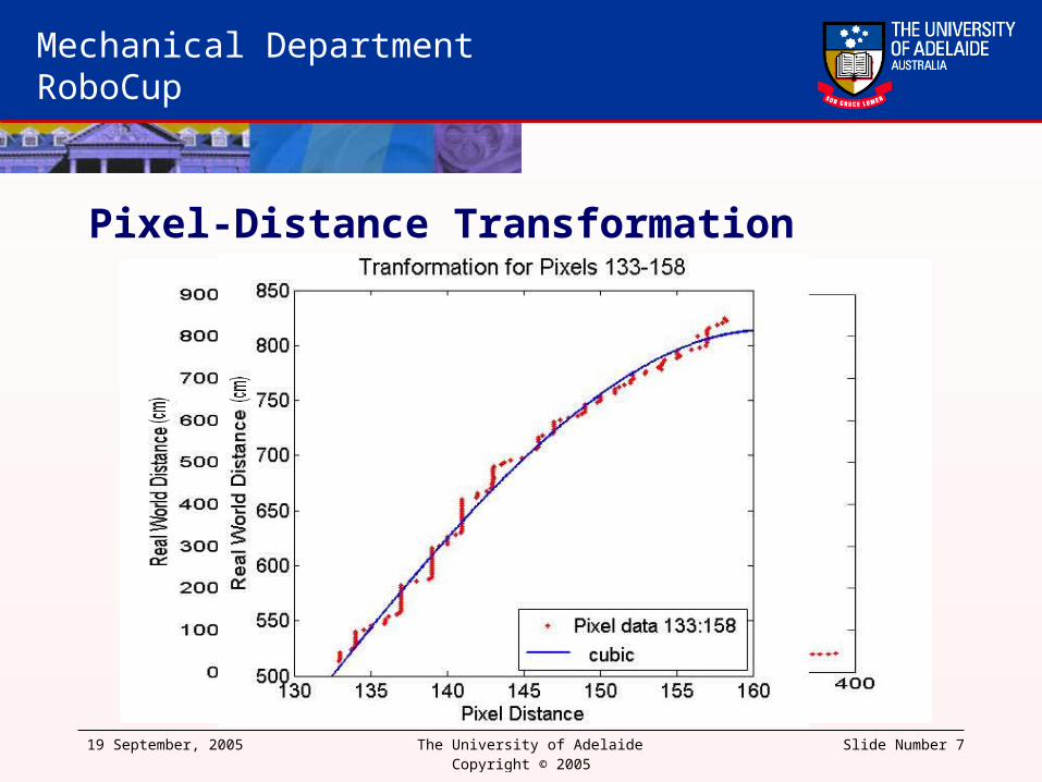
Vision Calibration
CMVision – Classifies pixels as a YUV colour CMVision returns pixel information of colour regions Obtaining the physical distance of an object requires mirror calibration Obtain the pixel distance and map this to the measured physical distance
19 September, 2005 The University of Adelaide Copyright © 2005 Slide Number 7
Mechanical Department RoboCup
Pixel-Distance Transformation

19 September, 2005 The University of Adelaide Copyright © 2005 Slide Number 8
Mechanical Department RoboCup
Localisation
Locate blue and green goalposts The centre of the goal-line is the
global origin The robot orientation is the slope of
the goal-line Using the global position and
orientation of the robot, the global position of an obstacle may be obtained from its position relative to the robot

19 September, 2005 The University of Adelaide Copyright © 2005 Slide Number 9
Mechanical Department RoboCup
Localisation
The projection of the ball causes the red region to be returned
The blue region represents the coordinates of interest
Using a compensation function, the ball may be located with an error of less than 8cm
19 September, 2005 The University of Adelaide Copyright © 2005 Slide Number 10
Mechanical Department RoboCup
Intelligence System
Controls and maintains links between vision system and controller Responsible for receiving and transmitting data from the subsystems Decides robots next location and/or action Uses path planner to obtain intermediate goals Determines if intermediate goals have been reached through a combination of
vision updates and encoder odometry Updates camera at timed intervals Transmits commands to controller on demand

19 September, 2005 The University of Adelaide Copyright © 2005 Slide Number 11
Mechanical Department RoboCup
Decision making process
Single player state Retrieve ball Goal is set behind ball on line from
goal Shoot for goal In case of obstacles between the
ball and goal, pass towards danger zones and/or team mates

19 September, 2005 The University of Adelaide Copyright © 2005 Slide Number 12
Mechanical Department RoboCup
Heuristic
Possession of ball Ball in view Robot orientation Angle to goal Distance to goal Obstacles in path

19 September, 2005 The University of Adelaide Copyright © 2005 Slide Number 13
Mechanical Department RoboCup
Future Versions
Multiplayer state Wireless communication between
teammates More complex decisions eg
Pass/Shoot/Dribble Player modes
– Defender– Goal keeper– Attacker– Midfielder
Players controlling field zones
Game modes– Man on Man – Offensive– Defensive– Long range shots– Space seeking– Time wasting– Aggressive
19 September, 2005 The University of Adelaide Copyright © 2005 Slide Number 14
Mechanical Department RoboCup
Path Planning
Receives position and geometric information about every object in the global frame
This module must produce a route that:
1. Avoids all obstacles
2. Accurately and reliably finds the destination
3. Minimises the path distance
4. Is computed in minimal time

19 September, 2005 The University of Adelaide Copyright © 2005 Slide Number 15
Mechanical Department RoboCup
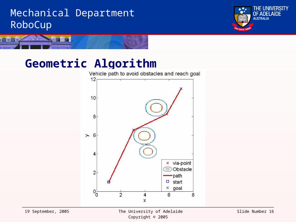
Geometric Algorithm
Uses geometry to find the optimal path using via-points The red circle is the obstacle, the blue circle is the minimum allowable
distance from the obstacle and the crosses are via-points
Start
Goal
VP 1 VP 2
o g
VP 1
VP 2
Start
Goal
19 September, 2005 The University of Adelaide Copyright © 2005 Slide Number 16
Mechanical Department RoboCup
Geometric Algorithm

19 September, 2005 The University of Adelaide Copyright © 2005 Slide Number 17
Mechanical Department RoboCup
Evaluation
Can solve complex paths Near optimal path generation Not infallible Computation Time < 150ms Does not yet account for moving
obstacles
19 September, 2005 The University of Adelaide Copyright © 2005 Slide Number 18
Mechanical Department RoboCup
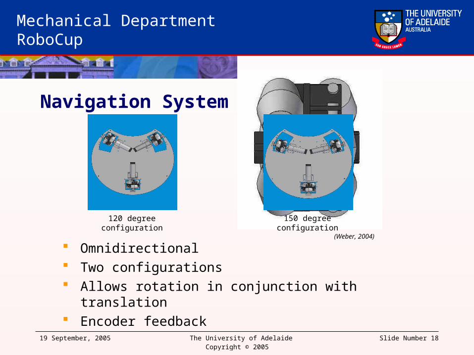
Navigation System
Omnidirectional Two configurations Allows rotation in conjunction with translation Encoder feedback
120 degree configuration
150 degree configuration
(Weber, 2004)

19 September, 2005 The University of Adelaide Copyright © 2005 Slide Number 19
Mechanical Department RoboCup
Controller
Designed on the DRAGON12 Development Board
Commands received from laptop via serial port (RS-232)
Responsible for controlling the three motors to move at specified velocities through the implementation of three separate PID feedback loops
Responsible for controlling the inlet/outlet valves of the kicker and its clutch release
(http://www.evbplus.com/dragon12.html)

19 September, 2005 The University of Adelaide Copyright © 2005 Slide Number 20
Mechanical Department RoboCup
PWM for Motor3
PWM for Motor2
PWM for Motor1Encoder feedback for Motor2
Encoder feedback for Motor3
Controller Plant+ -
Motor Speed PID Control
Controller
Responsible for generating PWM signals and Direction bits to motor driver
Responsible for reading Motor Encoder input
Responsible for PID feedback loop using Encoder
Responsible for controlling the inlet/outlet valves of the kicker and its clutch release
Air InletAir Outlet
Clutch

19 September, 2005 The University of Adelaide Copyright © 2005 Slide Number 21
Mechanical Department RoboCup
Controller
Encoder Feedback:2 16-Bit Pulse Accumulators1 Rising-Edge Accumulator
ParseCommand
SCI_ISR() -Command over serial port Raise flag
Heartbeat
overflow_ISR() –Timer overflow
dir_ISR()-Counter overflow
Increment Counter
Lower flag
If flag raised
main
Kicker Control
PID Feedback
Examples
Velocity Command“V 1024 -512 0 \n”
Kicker Rod Pullback Command
“T 3\n”
Release Clutch“K \n”
Discrete Time Interval for Information Processing
Information Processing
-Calculate the period of the encoder pulses for PID feedback loop
-Kicker Control - inlet/outlet of air to muscle
-Heartbeat – if no signal been received by controller, switch off motors
Calculate period of encoders
pulses

19 September, 2005 The University of Adelaide Copyright © 2005 Slide Number 22
Mechanical Department RoboCup
Kicker System Designed in 2004 by George Osborne and Christian Weber Based on a combination of a tension spring and an air muscle
using a spring clutch mechanism.
(Weber, 2004)

19 September, 2005 The University of Adelaide Copyright © 2005 Slide Number 23
Mechanical Department RoboCup
Kicker System
The air muscle contracts when it is pressurized, pulling the tension spring back by the length of contraction of the air muscle.
Air is released from the muscle The spring clutch mechanism
stops the kicker spring from relaxing when the muscle is relaxed.
Necessary because the muscle cannot provide enough displacement to pull back the spring back in one stage.
Clutch Release
To kick the ball, the on-off clutch is operated which
releases the kicker spring
Air InletAir Outlet
Once the muscle is fully relaxed, the clutch assembly is ready for the
next air intake.Repeat until fully retracted for goal
kicking or specified position for passing
(Weber, 2004)
19 September, 2005 The University of Adelaide Copyright © 2005 Slide Number 24
Mechanical Department RoboCup
Summary The project aims to integrate these hardware units into a reliable and
intelligent software system capable of deriving an optimal solution to the tasks of avoiding obstacles, and of finding, collecting and kicking the ball.
Currently, the vision, kicker, and controller system have been developed in low level software.
Current goals to achieve project aims Integration of individual software components. Testing and tuning for obstacle avoidance. Testing and tuning for ball collection and kicking during navigation.
19 September, 2005 The University of Adelaide Copyright © 2005 Slide Number 25
Mechanical Department RoboCup
Acknowledgements
Dr. Frank Wornle Project Supervisor
Mr. Silvio De Ieso Electronics and Instrumentation
Mr. George Osborne Kicker Instrumentation

19 September, 2005 The University of Adelaide Copyright © 2005 Slide Number 26
Mechanical Department RoboCup
Questions?
19 September, 2005 The University of Adelaide Copyright © 2005 Slide Number 27
Mechanical Department RoboCup
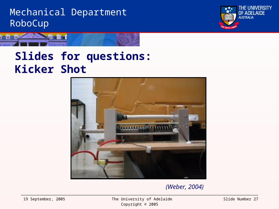
(Weber, 2004)
Slides for questions:Kicker Shot