Embed Size (px)
Citation preview
Energy Storage Technology Descriptions - EASE - European Associaton for Storage of Energy
Avenue Lacombé 59/8 - B - 1030 Brussels - tel: +32 02.743.29.82 - fax: +32 02.743.29.90 - [email protected] - www.ease-storage.eu
1. Technical description
A. Physical principles
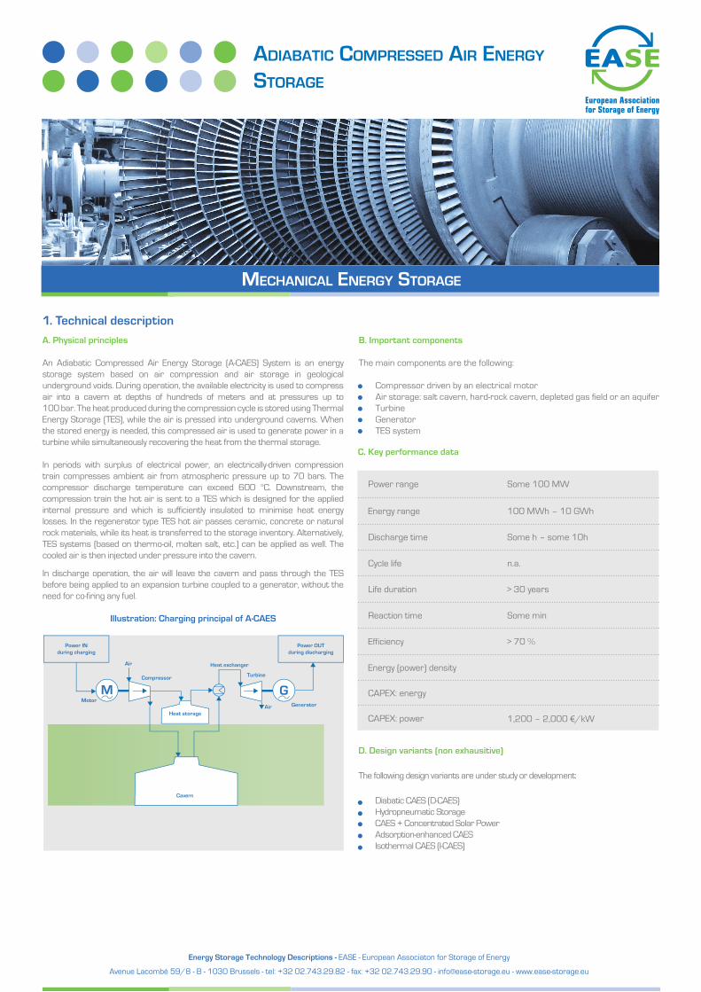
An Adiabatic Compressed Air Energy Storage (A-CAES) System is an energy storage system based on air compression and air storage in geological underground voids. During operation, the available electricity is used to compress air into a cavern at depths of hundreds of meters and at pressures up to 100 bar. The heat produced during the compression cycle is stored using Thermal Energy Storage (TES), while the air is pressed into underground caverns. When the stored energy is needed, this compressed air is used to generate power in a turbine while simultaneously recovering the heat from the thermal storage.
In periods with surplus of electrical power, an electrically-driven compression train compresses ambient air from atmospheric pressure up to 70 bars. The compressor discharge temperature can exceed 600 °C. Downstream, the compression train the hot air is sent to a TES which is designed for the applied internal pressure and which is sufficiently insulated to minimise heat energy losses. In the regenerator type TES hot air passes ceramic, concrete or natural rock materials, while its heat is transferred to the storage inventory. Alternatively, TES systems (based on thermo-oil, molten salt, etc.) can be applied as well. The cooled air is then injected under pressure into the cavern.
In discharge operation, the air will leave the cavern and pass through the TES before being applied to an expansion turbine coupled to a generator, without the need for co-firing any fuel.
C. Key performance data
B. Important components
The main components are the following:
Compressor driven by an electrical motorAir storage: salt cavern, hard-rock cavern, depleted gas field or an aquiferTurbineGeneratorTES system
Power IN during charging
Power OUTduring discharging
Generator
Turbine
Heat exchangerAir
Compressor
MotorAir
Cavern
Heat storage
Illustration: Charging principal of A-CAES
D. Design variants (non exhausitive)
The following design variants are under study or development:
Diabatic CAES (D-CAES)Hydropneumatic StorageCAES + Concentrated Solar PowerAdsorption-enhanced CAES Isothermal CAES (I-CAES)
AdiAbAtic compressed Air energy storAge
mechAnicAl energy storAge
Power range Some 100 MW
Energy range 100 MWh – 10 GWh
Discharge time Some h – some 10h
Cycle life n.a.
Reaction time
Life duration > 30 years
Efficiency
Some min
Energy (power) density
> 70 %
CAPEX: energy
CAPEX: power 1,200 – 2,000 €/kW
Energy Storage Technology Descriptions - EASE - European Associaton for Storage of Energy
Avenue Lacombé 59/8 - B - 1030 Brussels - tel: +32 02.743.29.82 - fax: +32 02.743.29.90 - [email protected] - www.ease-storage.eu
2. State of the art
A-CAES systems are in the process of demonstration and are not yet commercially available. They have been researched for a while starting with the AA-CAES project run under the European Commission Framework Programme 5 from 2003 to 2006. Currently, final plant designs are being analysed up to the level of construction details.
Projected units will have a storage capacity of one billion watt-hours (GWh) and generate electrical power of about 200 megawatt. Generally, the size of the heat storage requires a multi-train system design; so as a first step, smaller-scale demonstrators will be built. However, given the fact that the performance of A-CAES is achieved applying economies of scale, the smallest possible demonstrator will still be in the range close to 100 MW of power. A particular challenge is the maturity of A-CAES and the fact that costs are still at the very beginning of the cost learning curve. This means that the first devices will be particularly expensive and will need to be constructed in the most acceptable cost effective manner.
For implementation of such storage, both advanced turbo machines and an innovative high-temperature thermal energy storage concept are required. The availability of high temperature piping technology is another challenge. During the compression process, the temperature of the air may rise to more than 600 °C – thus creating challenging requirements for the compressor technology. In order to ensure that the resulting heat will not be lost, it will be extracted from the compressed air before it is stored, and absorbed by the separate TES unit. As soon as power is ready to be generated, just before the air will drive a turbine, the compressed air withdrawn from the cavern must be preheated, for which heat from the thermal energy storage is used. The adiabatic approach which preserves the heat of the compression step and utilises it in the expansion step differs from existing diabatic compressed-air solutions (in which the compression heat is lost and the fuel is used to heat up the air in discharge). This is the primary reason for its significantly higher level of efficiency and its CO
2
emission-free operation.
Suitable locations for compressed-air storage power plants are, in particular, regions with adequate geological salt structures, which can then be used to build underground caverns for the storage of large quantities of compressed air. It is beneficial if such salt structures are close to sources of cheap excess electrical energy like wind turbines (this is the case for the wind-rich regions in Europe) or close to areas of the grid that experience constraints.
3. Future developments
A-CAES systems will help to optimise the co-existence and smooth interac-tion of the individual energy sources. They have a particular potential to supply storage capacities for electric power of several hundred MW/MWh to some GW/GWh.
4. Relevance in EuropeThe Federal Government of Germany classifies the A-CAES technology as a priority area for development. The advances in A-CAES technology have even caught the attention on a European level and are being closely followed.
A-CAES systems have the potential to provide a large part of the necessary storage capacity for Europe’s future. A lot of regions have sufficient underground salt deposits for cavern construction. In Germany alone, more than 30 GW A-CAES were determined as potential power output, which is four times the installed pumped hydro power output. Just as with pumped hydro, the normal operation cycle of an A-CAES is daily. Heat can be stored for roughly one week. For longer periods with calm winds in Europe, A-CAES can enlarge the reaction time for start-up of the back-up power plants and smooth the gradients of the
5. Applications
Daily/weekly balancing
Arbitrage
Reserve & other standard Ancillary Services
Demand Services
6. Sources of information
EASE MembersRWE AG: ADELE Project AA-CAES-Project page in CORDIS