Embed Size (px)
Citation preview

1
MECHANICAL ENGINEERING SERVICES- DETAILED DESIGN REPORT
INSTALLATION OF AIR CONDITIONING SYSTEM ON THE AIRBRIDGES AT
O.R. TAMBO INTERNATIONAL AIRPORT
APRIL 2017
2
TABLE OF CONTENTS
1.INTRODUCTION .............................................................................................................. 3
2.SCOPE OF MECHANICAL SERVICES .......................................................................... 3
2.1.Air-conditioning and Ventilation (HVAC). ........................................................ 4
3. APPENDIX . ................................................................................................................... 24
4. STANDARDS & REGULATIONS…………………………………………..……….24
3
1.0 INTRODUCTION
This report presents the detailed design adjustments of Air conditioning Services for the
proposed air conditioning of fixed air bridges at O.R.Tambo International Airport,
Johannesburg. The adjustment to the design follows the original designs outlined in our
initial Preliminary Design Report, dated January 2017. The Scope of Mechanical Services
still remains the same and it includes the Heating Ventilation and Air Conditioning (HVAC).
This design adjustment report was developed consistent with the applicable South African
National Standards (SANS), of particular importance, SANS 204 for energy efficiency, the
new Green Building Star Rating System and American Society of Heating,
Refrigerating and Air-Conditioning Engineers (ASHRAE) Handbook.
The design adjustment approach and equipment selection report is also cognizant of South
Africa’s Green Building rating tool as launched by Green Building Council of South Africa
(GBCSA). This approach is the one which we adopted in the original design.
2.0 SCOPE OF MECHANICAL SERVICES
The scope of Mechanical Services is to provide concepts, design details and specifications
for all Selected Air Conditioning Services and Equipment for the air bridges. The proposed
services and equipment include:
• Air-conditioning and Ventilation (HVAC)
• Water Supply
• Plumbing
• BMS

4
2.1 AIR-CONDITIONING AND VENTILATION
The design consideration for the air-conditioning system include best practices for air
systems design, Air Handling Units, ducts, terminal units diffusors, and controls, with
emphasis on getting the air distribution system components to work together in an integral
fashion, and providing the desired comfort, and the key topics critical to optimal design
include the following:
• Early Design Issues,
• Zone Issues,
• System Selection Issues,
• Duct design Issues,
• Control Issues.
• In addition to the above issues, for this design, the selected important criterion
considered includes:
• Occupancy
• Noise and vibration control
• Air System Design Requirements
• Location of Mechanical equipment
• Green Building Consideration
2.1.1 Early Design Issues Considerations
According to an old adage,” An ounce of prevention is worth a pound of cure.” This holds
true for building design. An extra hour carefully spent in early design can save weeks of
time later in the process, not to mention reduced construction costs, and reduced operating
costs. Early design issues taken into consideration and informed the design are discussed in
detail in sections that follow include:
• Integrated Design Issues
• HVAC System Selection
• Shaft Location ,coordination and size
• Auxiliary Loads
• Code Ventilation Requirements
• Determining Internal Loads

5
Integrated Design Issues
Traditional design is a fragmented process where each consultant (architect, mechanical
engineers, electrical engineers...) work exclusively on aspects of the design that fall under
their scope of services. The adopted approach in this project is a more Integrated Design
process that has a more collaborative multidiscipline approach to better integrate the
building design, systems and controls. Issues that are not traditionally the purview of the
mechanical engineer, glazing selection, and shading devises, lighting were emphasized.
HVAC and Architectural Coordination Issues were identified for an integrated design; these
issues are provided in Table 1.
Table 1: HVAC and Architectural Coordination Issues
Zoning
We grouped spaces with similar ventilation requirements,
cooling loads and occupancy schedules resulting in first cost
savings (due to fewer zones) and energy savings (due to
opportunities to shut off portions of the system).
Thermostatic controls have been placed in each zone and
these will be linked to the Building Automation System
(BAS) with direct digital control occupancy sensors if
provided. For perimeter zones, we grouped spaces with the
same orientation of glass and/walls (facades).
Duct Design
We have as much as possible selected straight paths from the
fan coil unit to the interior spaces. This will result in both
lower costs in energy and procurement and installation. We
minimized duct bends as much as practically possible and
used standard lengths straight ducts in order to reduce the
6
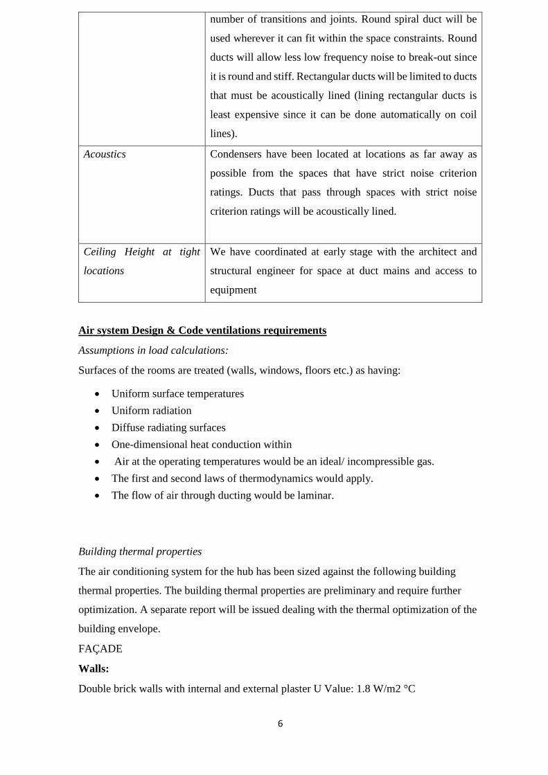
number of transitions and joints. Round spiral duct will be
used wherever it can fit within the space constraints. Round
ducts will allow less low frequency noise to break-out since
it is round and stiff. Rectangular ducts will be limited to ducts
that must be acoustically lined (lining rectangular ducts is
least expensive since it can be done automatically on coil
lines).
Acoustics
Condensers have been located at locations as far away as
possible from the spaces that have strict noise criterion
ratings. Ducts that pass through spaces with strict noise
criterion ratings will be acoustically lined.
Ceiling Height at tight
locations
We have coordinated at early stage with the architect and
structural engineer for space at duct mains and access to
equipment
Air system Design & Code ventilations requirements
Assumptions in load calculations:
Surfaces of the rooms are treated (walls, windows, floors etc.) as having:
• Uniform surface temperatures
• Uniform radiation
• Diffuse radiating surfaces
• One-dimensional heat conduction within
• Air at the operating temperatures would be an ideal/ incompressible gas.
• The first and second laws of thermodynamics would apply.
• The flow of air through ducting would be laminar.
Building thermal properties
The air conditioning system for the hub has been sized against the following building
thermal properties. The building thermal properties are preliminary and require further
optimization. A separate report will be issued dealing with the thermal optimization of the
building envelope.
FAÇADE
Walls:
Double brick walls with internal and external plaster U Value: 1.8 W/m2 °C
7
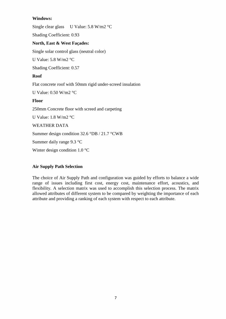
Windows:
Single clear glass U Value: 5.8 W/m2 °C
Shading Coefficient: 0.93
North, East & West Façades:
Single solar control glass (neutral color)
U Value: 5.8 W/m2 °C
Shading Coefficient: 0.57
Roof
Flat concrete roof with 50mm rigid under-screed insulation
U Value: 0.50 W/m2 °C
Floor
250mm Concrete floor with screed and carpeting
U Value: 1.8 W/m2 °C
WEATHER DATA
Summer design condition 32.6 °DB / 21.7 °CWB
Summer daily range 9.3 °C
Winter design condition 1.0 °C
Air Supply Path Selection
The choice of Air Supply Path and configuration was guided by efforts to balance a wide
range of issues including first cost, energy cost, maintenance effort, acoustics, and
flexibility. A selection matrix was used to accomplish this selection process. The matrix
allowed attributes of different system to be compared by weighting the importance of each
attribute and providing a ranking of each system with respect to each attribute.
8
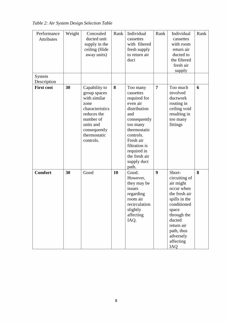
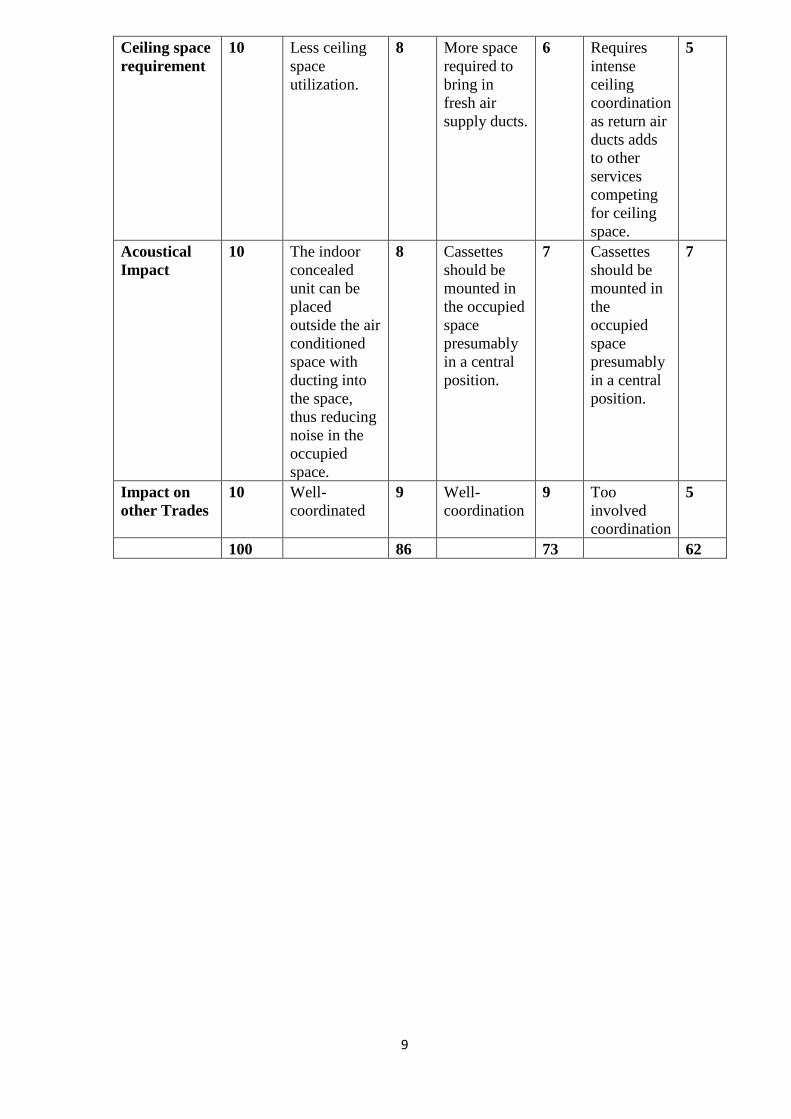
Table 2: Air System Design Selection Table
Performance
Attributes
Weight Concealed
ducted unit
supply in the
ceiling (Hide
away units)
Rank Individual
cassettes
with filtered
fresh supply
to return air
duct
Rank Individual
cassettes
with room
return air
ducted to
the filtered
fresh air
supply
Rank
System
Description
First cost 30 Capability to
group spaces
with similar
zone
characteristics
reduces the
number of
units and
consequently
thermostatic
controls.
8 Too many
cassettes
required for
even air
distribution
and
consequently
too many
thermostatic
controls.
Fresh air
filtration is
required in
the fresh air
supply duct
path.
7 Too much
involved
ductwork
routing in
ceiling void
resulting in
too many
fittings
6
Comfort 30 Good 10 Good.
However,
they may be
issues
regarding
room air
recirculation
slightly
affecting
IAQ.
9 Short-
circuiting of
air might
occur when
the fresh air
spills in the
conditioned
space
through the
ducted
return air
path, thus
adversely
affecting
IAQ
8
9
Ceiling space
requirement
10 Less ceiling
space
utilization.
8 More space
required to
bring in
fresh air
supply ducts.
6 Requires
intense
ceiling
coordination
as return air
ducts adds
to other
services
competing
for ceiling
space.
5
Acoustical
Impact
10 The indoor
concealed
unit can be
placed
outside the air
conditioned
space with
ducting into
the space,
thus reducing
noise in the
occupied
space.
8 Cassettes
should be
mounted in
the occupied
space
presumably
in a central
position.
7 Cassettes
should be
mounted in
the
occupied
space
presumably
in a central
position.
7
Impact on
other Trades
10 Well-
coordinated
9 Well-
coordination
9 Too
involved
coordination
5
100 86 73 62

10
HVAC System Selection
The choice of HVAC System was guided by efforts to balance a wide range of issues
including first cost, energy cost, maintenance effort, acoustics, and flexibility. A system
selection matrix was used to accomplish this selection process. The matrix allows attributes
of different system to be compared by weighting the importance of each attribute and
providing a ranking of each system with respect to each attribute.
Table 3: HVAC Systems Selection Table
Performance
Attributes
Weight Central Chilled Water
System
(Air-cooled) with VAV
Rank VRV System Rank
System
Description
Central cooling chillers and
air cooled mounted on the
roof with a number of air
handling units in positions
near the rooms being
served.
Variable Refrigerant
Volume system with VRV
condensers on roof top
connected to indoor units in
the ceiling void by means of
refrigerant pipe work.
HVAC First
Price Costs
20 High cost 8 High cost 7
Capacity
Limitation
10 Chiller capacity could be
slightly limited by concerns
to balance weight on roof
top chillers and the available
maximum cooling load for a
specific required structural
load. However, this is not so
serious for air cooled
chillers and we could
therefore say no limitations.
9 No limitation. More units
could be evenly spread on
roof top in order to meet
capacity requirements.
10
Floor Space
Requirement
s
10 Relatively larger spaces
required.
6 Smallest floor space
required
8
Energy
Efficiency
Normal
Operation
10 Water cooling reduces
overall energy costs.
However, the whole plant
has to come into operation
even though a few spaces
require cooling/heating.
6 Low energy requirements
due to close control of
refrigerant floor. Also, it is
not necessary to operate
whole plant when not all the
spaces require
cooling/heating.
7
Maintenance
Cost and
Reliability
10 Parallel connection of
chillers reduces the number
of chillers required; This
7 Multiple small compressors
with invertor technology.
8
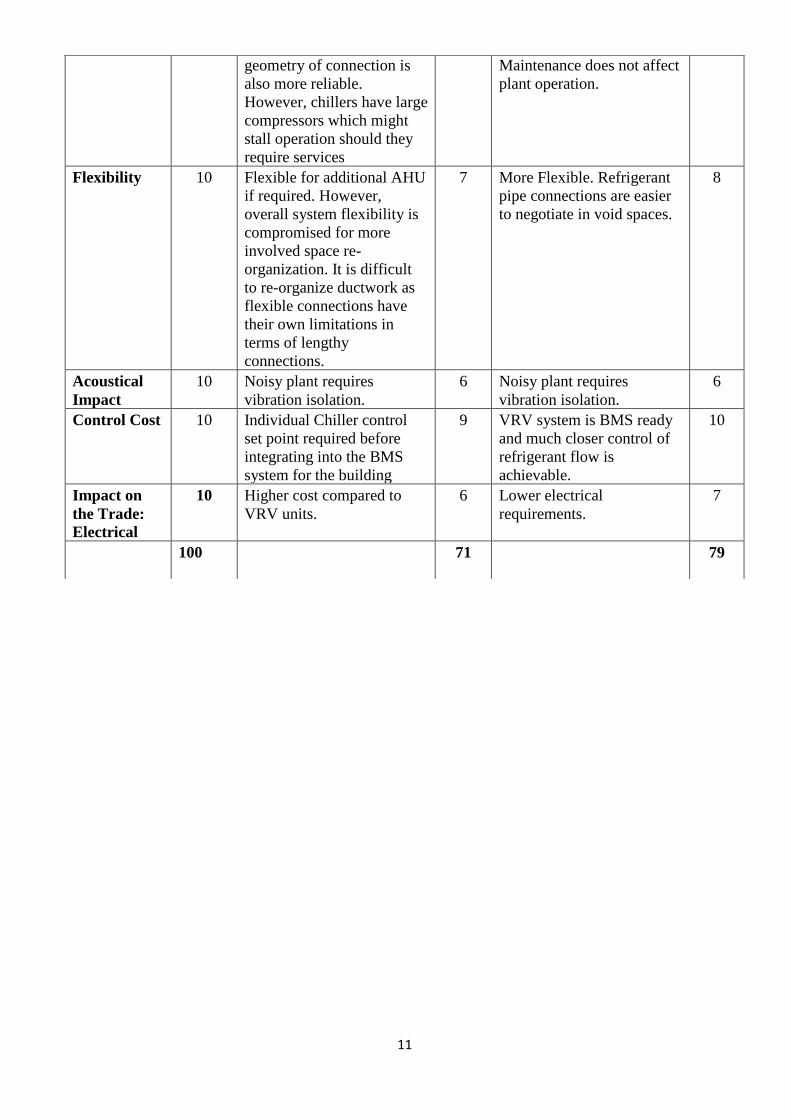
11
geometry of connection is
also more reliable.
However, chillers have large
compressors which might
stall operation should they
require services
Maintenance does not affect
plant operation.
Flexibility 10 Flexible for additional AHU
if required. However,
overall system flexibility is
compromised for more
involved space re-
organization. It is difficult
to re-organize ductwork as
flexible connections have
their own limitations in
terms of lengthy
connections.
7 More Flexible. Refrigerant
pipe connections are easier
to negotiate in void spaces.
8
Acoustical
Impact
10 Noisy plant requires
vibration isolation.
6 Noisy plant requires
vibration isolation.
6
Control Cost 10 Individual Chiller control
set point required before
integrating into the BMS
system for the building
9 VRV system is BMS ready
and much closer control of
refrigerant flow is
achievable.
10
Impact on
the Trade:
Electrical
10 Higher cost compared to
VRV units.
6 Lower electrical
requirements.
7
100 71 79
12
General Comparison of VRV System and Central Chiller System
In today's business environments, higher use of technology and greater demands for
comfortable surroundings lead to an increased demand for air conditioning. Customers,
equipment & staff alike require comfortable surroundings, which can only be achieved by
utilizing such equipment.
Air-conditioning units are available in five main categories namely:
• Split system air conditioners.
• Multiple & VRV systems.
• Portable air conditioners.
• Rooftop packaged products.
• Chillers for air handling plants.
However, for the purposes of the establishment only the split system air conditioners,
multiple & VRV systems and Chillers with air handling units will be considered.
Split system air-conditioning units.
A split system air-conditioning unit consist of an outdoor condensing unit, and an indoor
fan coil unit. The indoor units are available in several different styles to suit the type of
room.
Modern air conditioners are quiet and reliable, the indoor units unobtrusive, and can be
installed almost anywhere.
Indoor Units
• Wall mounted: Installed at high level on vertical surfaces in any
application.
• Ceiling cassette: Recessed into ceiling voids, offices, shops, boardrooms,
classrooms.
• Ceiling suspended: Installed onto horizontal ceiling surfaces, ideal for
refurbishment.
• Floor mounted: Installed at low level, board rooms, conference rooms,
conservatories.
• Ducted: Installed within ceiling voids, for large offices, conference rooms
meeting rooms etc.
Outdoor Units
Each indoor unit is connected to an outdoor condensing unit. The units are installed
external to the building; all units are quiet in operation and offer high efficiency at
minimal running costs.
13
Multiple and VRV Air Conditioning Systems
Suitable for larger buildings such as offices and multiple room applications, the
multiple or variable refrigerant volume system (VRV) can be a wise option.
Multiple Systems
The multiple system allows multiple indoor units to be connected to one outdoor
condensing unit. This system has the advantages of space saving and lower
installation and future maintenance costs. Cooling only, or heating and cooling
models are available.
Variable refrigerant volume systems (VRV)
The VRV system has been developed for large buildings with a large number of
rooms. The system is available in several different formats:
Cooling only inverter system
One or multiple condensing units are attached to several indoor units. The system
will vary the cooling capacity depending on the number of indoor units in use and
the amount of work they need to do. This type of system has the advantage of lower
running and lower installation costs.
Heat pump inverter system
Similar to the cooling only inverter system, however, in the heat pump system the
indoor units can heat or cool, as long as all units are in the same mode (Heat or
Cool).
The system is ideal for large open plan offices etc.
Heat recovery systems
The most sophisticated VRV system, the system utilizes one or more outdoor
condensing units connected to several indoor units. The system allows the user to
select heating or cooling as desired, but has the advantage of recovering heat from
one room and passing it to another, and vice versa. For example, a room with a
large amount of computer equipment may require cooling all year round, whereas
a meeting room may require heating. The system will recover heat from the
computer room and deliver it to the meetingroom; this can be done from multiple
rooms at the same time.
14
Chillers for Air Handling Plant
Suitable for large air handling plant applications, water Chillers and direct
expansion Chillers are available from small cooling capacities to large multiple
capacities.
The cooling units can be arranged to suit the particular application required.
A range of units are available from quality manufacturers, with a choice of ozone
friendly refrigerants.
Due to the existing building’s structure and proposed functionality, we recommend
that air-conditioning systems of either the split heat pump type (unitary systems or
VRV systems) or air cooled chiller system be installed to serve the building.
Below is a comparison of chilled water system with variable air volume (VAV)
ducted air handling unit systems and VRV systems.
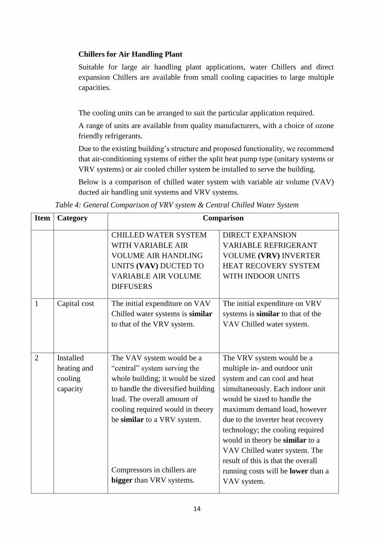
Table 4: General Comparison of VRV system & Central Chilled Water System
Item Category Comparison
CHILLED WATER SYSTEM
WITH VARIABLE AIR
VOLUME AIR HANDLING
UNITS (VAV) DUCTED TO
VARIABLE AIR VOLUME
DIFFUSERS
DIRECT EXPANSION
VARIABLE REFRIGERANT
VOLUME (VRV) INVERTER
HEAT RECOVERY SYSTEM
WITH INDOOR UNITS
1 Capital cost The initial expenditure on VAV
Chilled water systems is similar
to that of the VRV system.
The initial expenditure on VRV
systems is similar to that of the
VAV Chilled water system.
2 Installed
heating and
cooling
capacity
The VAV system would be a
“central” system serving the
whole building; it would be sized
to handle the diversified building
load. The overall amount of
cooling required would in theory
be similar to a VRV system.
Compressors in chillers are
bigger than VRV systems.
The VRV system would be a
multiple in- and outdoor unit
system and can cool and heat
simultaneously. Each indoor unit
would be sized to handle the
maximum demand load, however
due to the inverter heat recovery
technology; the cooling required
would in theory be similar to a
VAV Chilled water system. The
result of this is that the overall
running costs will be lower than a
VAV system.
15
Multiple compressors in outdoor
units result in minimum power
surges ensures a 50% standby
facility and are smaller, and faster
and cheaper to replace.
Delivers highly efficient
performance, contributing to better
Energy savings than a VAV
system.
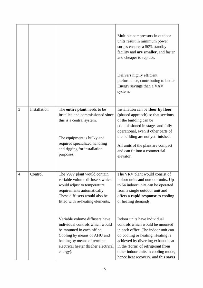
3 Installation The entire plant needs to be
installed and commissioned since
this is a central system.
The equipment is bulky and
required specialized handling
and rigging for installation
purposes.
Installation can be floor by floor
(phased approach) so that sections
of the building can be
commissioned in stages and fully
operational, even if other parts of
the building are not yet finished.
All units of the plant are compact
and can fit into a commercial
elevator.
4 Control The VAV plant would contain
variable volume diffusers which
would adjust to temperature
requirements automatically.
These diffusers would also be
fitted with re-heating elements.
Variable volume diffusers have
individual controls which would
be mounted in each office.
Cooling by means of AHU and
heating by means of terminal
electrical heater (higher electrical
energy).
The VRV plant would consist of
indoor units and outdoor units. Up
to 64 indoor units can be operated
from a single outdoor unit and
offers a rapid response to cooling
or heating demands.
Indoor units have individual
controls which would be mounted
in each office. The indoor unit can
do cooling or heating. Heating is
achieved by diverting exhaust heat
in the (form) of refrigerant from
other indoor units in cooling mode,
hence heat recovery, and this saves
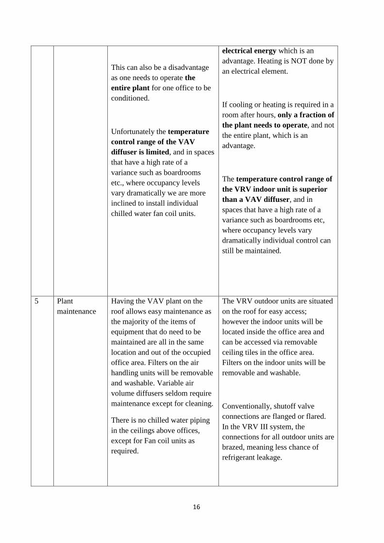
16
This can also be a disadvantage
as one needs to operate the
entire plant for one office to be
conditioned.
Unfortunately the temperature
control range of the VAV
diffuser is limited, and in spaces
that have a high rate of a
variance such as boardrooms
etc., where occupancy levels
vary dramatically we are more
inclined to install individual
chilled water fan coil units.
electrical energy which is an
advantage. Heating is NOT done by
an electrical element.
If cooling or heating is required in a
room after hours, only a fraction of
the plant needs to operate, and not
the entire plant, which is an
advantage.
The temperature control range of
the VRV indoor unit is superior
than a VAV diffuser, and in
spaces that have a high rate of a
variance such as boardrooms etc,
where occupancy levels vary
dramatically individual control can
still be maintained.
5 Plant
maintenance
Having the VAV plant on the
roof allows easy maintenance as
the majority of the items of
equipment that do need to be
maintained are all in the same
location and out of the occupied
office area. Filters on the air
handling units will be removable
and washable. Variable air
volume diffusers seldom require
maintenance except for cleaning.
There is no chilled water piping
in the ceilings above offices,
except for Fan coil units as
required.
The VRV outdoor units are situated
on the roof for easy access;
however the indoor units will be
located inside the office area and
can be accessed via removable
ceiling tiles in the office area.
Filters on the indoor units will be
removable and washable.
Conventionally, shutoff valve
connections are flanged or flared.
In the VRV III system, the
connections for all outdoor units are
brazed, meaning less chance of
refrigerant leakage.

17
Relatively low maintenance costs
Relatively low maintenance costs
6 Plant Position As mentioned above the VAV
plant would be roof mounted.
This equipment is heavy and
could require a Structural
Engineer’s approval. If the
plant is too heavy though, adding
in support etc. could be a costly
exercise.
Air handling units have to be
installed close to the floor they
are serving. Ducting would
require large openings in walls as
well as larger ceiling voids.
As mentioned above the VRV
condensing units would be roof
mounted. This equipment is less
heavy than a VAV system (e.g.
chiller or large AHU’s), and the
unitary outdoor units can be evenly
distributed on the roof structure
without compromising the
buildings structural integrity.
Indoor units will be mounted in the
ceiling void (min 600mm clear),
and condensate would be drained /
pumped to the nearest drain point.
7 Power
requirements
and electrical
running costs
Having central plant means that
the power supply would be in
one place. Wiring to the heating
elements on the terminals would
be from the roof plant. The
(a) initial and
(b) Running power input
requirements for the VAV
system would be higher than a
VRV.
The Coefficient of Performance
(COP):
COP of VAV in summer = 2.5.
COP of VAV in winter = 1.0
The power supply would be to the
roof plant. Wiring to the indoor
units would be from the roof plant.
Due to diversification and the
inverter heat recovery technology,
the
(a) initial and
(b) Running power input
requirements for the VRV system
would be lower than a VAV
system.
The Coefficient of Performance
(COP):
COP of VRV in summer = 3.5
COP of VRV in winter = 3.0
The electricity consumption for a
VRV during summer will be (30%)
less than a VAV system and (66%)
less during winter.

18
8 Aesthetics VAV diffusers would be far
more aesthetically pleasing than
wall mounted split units.
Indoor units could vary from
(a) 4-way blow ceiling mounted
cassette to fit into a standard
600x600 ceiling tile
(b) a concealed type hide-away fan
coil unit connected to a diffuser
(c) floor standing or
(d) Midwall mounted.
9 Flexibility Easy to alter diffuser positions to
suit revised internal layouts since
they are connected with flexible
diffusers. However, more
difficult to alter main duct
positions for space re-
organizations hence overall
flexibility compromised.
Indoor DX units can be
repositioned but is not as flexible as
diffusers. However, for more
involved space re-organization, the
indoor DX units can move without
hindrance.
10 Noise Indoor VAV diffusers have low
noise levels <NC35
Indoor units have low noise levels
and are comparable to VAV
diffusers.
Outdoor plant noise levels are less
than Chillers.
11 Plant lifetime Long life of plant approximately
20 to 25 years.
Long life of plant approximately 15
to 20 years.
We choose VRV system because of its energy efficiency and other benefits as outlined
above. However, in other bridges like Alpha 7- 13 and Charlie 7-8 we had to choose
connecting to the chilled water system because of space constrains. The mass of the
bridges are made of corrugated sheets and glass, hence the bridges cannot sustain the
weight of the condensers and there is no space on the ground to install the condensers.
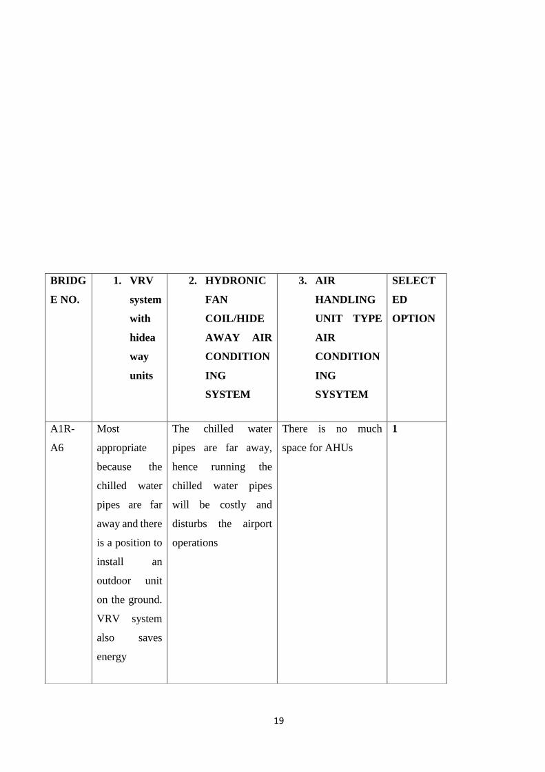
19
BRIDG
E NO.
1. VRV
system
with
hidea
way
units
2. HYDRONIC
FAN
COIL/HIDE
AWAY AIR
CONDITION
ING
SYSTEM
3. AIR
HANDLING
UNIT TYPE
AIR
CONDITION
ING
SYSYTEM
SELECT
ED
OPTION
A1R-
A6
Most
appropriate
because the
chilled water
pipes are far
away and there
is a position to
install an
outdoor unit
on the ground.
VRV system
also saves
energy
The chilled water
pipes are far away,
hence running the
chilled water pipes
will be costly and
disturbs the airport
operations
There is no much
space for AHUs
1
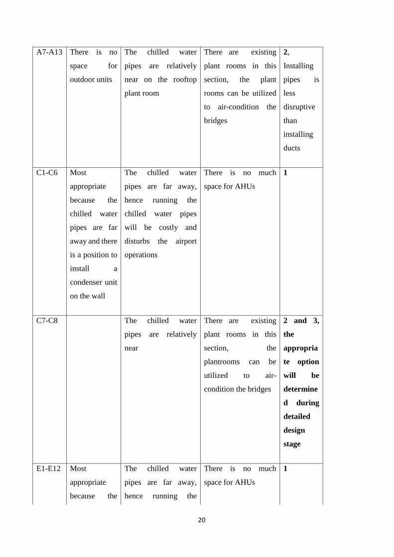
20
A7-A13 There is no
space for
outdoor units
The chilled water
pipes are relatively
near on the rooftop
plant room
There are existing
plant rooms in this
section, the plant
rooms can be utilized
to air-condition the
bridges
2,
Installing
pipes is
less
disruptive
than
installing
ducts
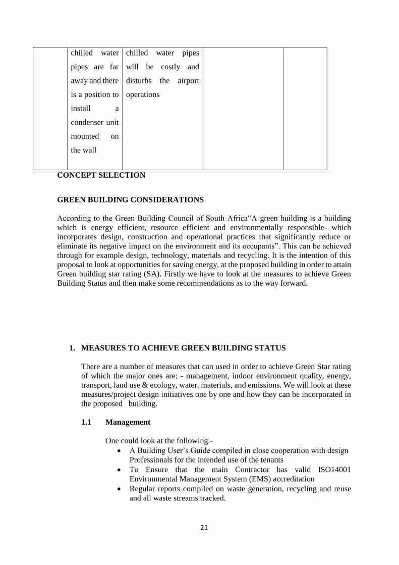
C1-C6 Most
appropriate
because the
chilled water
pipes are far
away and there
is a position to
install a
condenser unit
on the wall
The chilled water
pipes are far away,
hence running the
chilled water pipes
will be costly and
disturbs the airport
operations
There is no much
space for AHUs
1
C7-C8 The chilled water
pipes are relatively
near
There are existing
plant rooms in this
section, the
plantrooms can be
utilized to air-
condition the bridges
2 and 3,
the
appropria
te option
will be
determine
d during
detailed
design
stage
E1-E12 Most
appropriate
because the
The chilled water
pipes are far away,
hence running the
There is no much
space for AHUs
1
21
CONCEPT SELECTION
GREEN BUILDING CONSIDERATIONS
According to the Green Building Council of South Africa“A green building is a building
which is energy efficient, resource efficient and environmentally responsible- which
incorporates design, construction and operational practices that significantly reduce or
eliminate its negative impact on the environment and its occupants”. This can be achieved
through for example design, technology, materials and recycling. It is the intention of this
proposal to look at opportunities for saving energy, at the proposed building in order to attain
Green building star rating (SA). Firstly we have to look at the measures to achieve Green
Building Status and then make some recommendations as to the way forward.
1. MEASURES TO ACHIEVE GREEN BUILDING STATUS
There are a number of measures that can used in order to achieve Green Star rating
of which the major ones are: - management, indoor environment quality, energy,
transport, land use & ecology, water, materials, and emissions. We will look at these
measures/project design initiatives one by one and how they can be incorporated in
the proposed building.
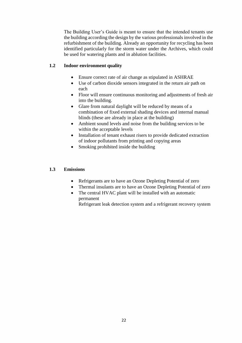
1.1 Management
One could look at the following:-
• A Building User’s Guide compiled in close cooperation with design
Professionals for the intended use of the tenants
• To Ensure that the main Contractor has valid ISO14001
Environmental Management System (EMS) accreditation
• Regular reports compiled on waste generation, recycling and reuse
and all waste streams tracked.
chilled water
pipes are far
away and there
is a position to
install a
condenser unit
mounted on
the wall
chilled water pipes
will be costly and
disturbs the airport
operations
22
The Building User’s Guide is meant to ensure that the intended tenants use
the building according the design by the various professionals involved in the
refurbishment of the building. Already an opportunity for recycling has been
identified particularly for the storm water under the Archives, which could
be used for watering plants and in ablution facilities.
1.2 Indoor environment quality
• Ensure correct rate of air change as stipulated in ASHRAE
• Use of carbon dioxide sensors integrated in the return air path on
each
• Floor will ensure continuous monitoring and adjustments of fresh air
into the building.
• Glare from natural daylight will be reduced by means of a
combination of fixed external shading devices and internal manual
blinds (these are already in place at the building)
• Ambient sound levels and noise from the building services to be
within the acceptable levels
• Installation of tenant exhaust risers to provide dedicated extraction
of indoor pollutants from printing and copying areas
• Smoking prohibited inside the building
1.3 Emissions
• Refrigerants are to have an Ozone Depleting Potential of zero
• Thermal insulants are to have an Ozone Depleting Potential of zero
• The central HVAC plant will be installed with an automatic
permanent
Refrigerant leak detection system and a refrigerant recovery system
23
2. RECOMMENDATIONS AND CONCLUSION
Clearly as outlined above there exists opportunities at the building to achieve Green
Building status. The following recommendations should be noted:-
• That there be total commitment from all the stake holders
• The planning process should set out clearly a benchmark for the
Green star rating that is practically achievable and this should be
incorporated in the designs
• The tender process should ensure that a competent contractor is
appointed
• Have proper project management during the construction phase to
ensure the contractor adheres to the design parameters
If the project is properly planned with all stakeholder involvement and correctly
executed, then achievement of the Green star rating is possible.
24
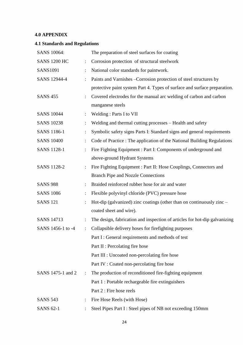
4.0 APPENDIX
4.1 Standards and Regulations
SANS 10064: The preparation of steel surfaces for coating
SANS 1200 HC : Corrosion protection of structural steelwork
SANS1091 : National color standards for paintwork.
SANS 12944-4 : Paints and Varnishes –Corrosion protection of steel structures by
protective paint system Part 4. Types of surface and surface preparation.
SANS 455 : Covered electrodes for the manual arc welding of carbon and carbon
manganese steels
SANS 10044 : Welding : Parts I to VII
SANS 10238 : Welding and thermal cutting processes – Health and safety
SANS 1186-1 : Symbolic safety signs Parts I: Standard signs and general requirements
SANS 10400 : Code of Practice : The application of the National Building Regulations
SANS 1128-1 : Fire Fighting Equipment : Part I: Components of underground and
above-ground Hydrant Systems
SANS 1128-2 : Fire Fighting Equipment : Part II: Hose Couplings, Connectors and
Branch Pipe and Nozzle Connections
SANS 988 : Braided reinforced rubber hose for air and water
SANS 1086 : Flexible polyvinyl chloride (PVC) pressure hose
SANS 121 : Hot-dip (galvanized) zinc coatings (other than on continuously zinc –
coated sheet and wire).
SANS 14713 : The design, fabrication and inspection of articles for hot-dip galvanizing
SANS 1456-1 to -4 : Collapsible delivery hoses for firefighting purposes
Part I : General requirements and methods of test
Part II : Percolating fire hose
Part III : Uncoated non-percolating fire hose
Part IV : Coated non-percolating fire hose
SANS 1475-1 and 2 : The production of reconditioned fire-fighting equipment
Part 1 : Portable rechargeable fire extinguishers
Part 2 : Fire hose reels
SANS 543 : Fire Hose Reels (with Hose)
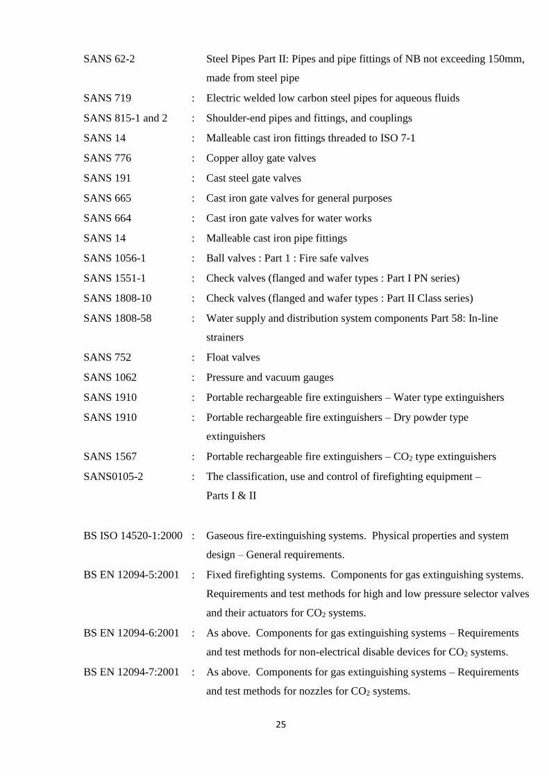
SANS 62-1 : Steel Pipes Part I : Steel pipes of NB not exceeding 150mm
25
SANS 62-2 Steel Pipes Part II: Pipes and pipe fittings of NB not exceeding 150mm,
made from steel pipe
SANS 719 : Electric welded low carbon steel pipes for aqueous fluids
SANS 815-1 and 2 : Shoulder-end pipes and fittings, and couplings
SANS 14 : Malleable cast iron fittings threaded to ISO 7-1
SANS 776 : Copper alloy gate valves
SANS 191 : Cast steel gate valves
SANS 665 : Cast iron gate valves for general purposes
SANS 664 : Cast iron gate valves for water works
SANS 14 : Malleable cast iron pipe fittings
SANS 1056-1 : Ball valves : Part 1 : Fire safe valves
SANS 1551-1 : Check valves (flanged and wafer types : Part I PN series)
SANS 1808-10 : Check valves (flanged and wafer types : Part II Class series)
SANS 1808-58 : Water supply and distribution system components Part 58: In-line
strainers
SANS 752 : Float valves
SANS 1062 : Pressure and vacuum gauges
SANS 1910 : Portable rechargeable fire extinguishers – Water type extinguishers
SANS 1910 : Portable rechargeable fire extinguishers – Dry powder type
extinguishers
SANS 1567 : Portable rechargeable fire extinguishers – CO2 type extinguishers
SANS0105-2 : The classification, use and control of firefighting equipment –
Parts I & II
BS ISO 14520-1:2000 : Gaseous fire-extinguishing systems. Physical properties and system
design – General requirements.
BS EN 12094-5:2001 : Fixed firefighting systems. Components for gas extinguishing systems.
Requirements and test methods for high and low pressure selector valves
and their actuators for CO2 systems.
BS EN 12094-6:2001 : As above. Components for gas extinguishing systems – Requirements
and test methods for non-electrical disable devices for CO2 systems.
BS EN 12094-7:2001 : As above. Components for gas extinguishing systems – Requirements
and test methods for nozzles for CO2 systems.
26
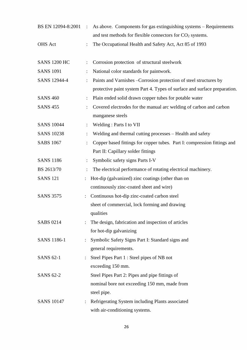
BS EN 12094-8:2001 : As above. Components for gas extinguishing systems – Requirements
and test methods for flexible connectors for CO2 systems.
OHS Act : The Occupational Health and Safety Act, Act 85 of 1993
SANS 1200 HC : Corrosion protection of structural steelwork
SANS 1091 : National color standards for paintwork.
SANS 12944-4 : Paints and Varnishes –Corrosion protection of steel structures by
protective paint system Part 4. Types of surface and surface preparation.
SANS 460 : Plain ended solid drawn copper tubes for potable water
SANS 455 : Covered electrodes for the manual arc welding of carbon and carbon
manganese steels
SANS 10044 : Welding : Parts I to VII
SANS 10238 : Welding and thermal cutting processes – Health and safety
SABS 1067 : Copper based fittings for copper tubes. Part I: compression fittings and
Part II: Capillary solder fittings
SANS 1186 : Symbolic safety signs Parts I-V
BS 2613/70 : The electrical performance of rotating electrical machinery.
SANS 121 : Hot-dip (galvanized) zinc coatings (other than on
continuously zinc-coated sheet and wire)
SANS 3575 : Continuous hot-dip zinc-coated carbon steel
sheet of commercial, lock forming and drawing
qualities
SABS 0214 : The design, fabrication and inspection of articles
for hot-dip galvanizing
SANS 1186-1 : Symbolic Safety Signs Part I: Standard signs and
general requirements.
SANS 62-1 : Steel Pipes Part 1 : Steel pipes of NB not
exceeding 150 mm.
SANS 62-2 Steel Pipes Part 2: Pipes and pipe fittings of
nominal bore not exceeding 150 mm, made from
steel pipe.
SANS 10147 : Refrigerating System including Plants associated
with air-conditioning systems.
27
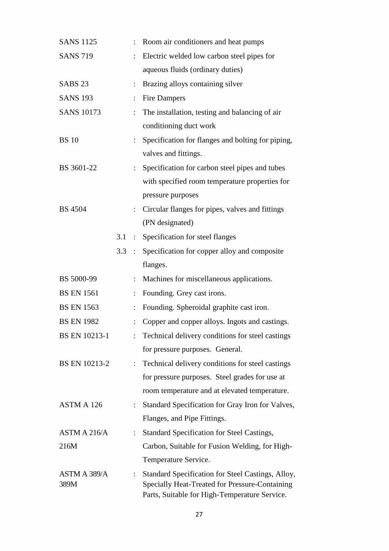
SANS 1125 : Room air conditioners and heat pumps
SANS 719 : Electric welded low carbon steel pipes for
aqueous fluids (ordinary duties)
SABS 23 : Brazing alloys containing silver
SANS 193 : Fire Dampers
SANS 10173 : The installation, testing and balancing of air
conditioning duct work
BS 10 : Specification for flanges and bolting for piping,
valves and fittings.
BS 3601-22 : Specification for carbon steel pipes and tubes
with specified room temperature properties for
pressure purposes
BS 4504 : Circular flanges for pipes, valves and fittings
(PN designated)
3.1 : Specification for steel flanges
3.3 : Specification for copper alloy and composite
flanges.
BS 5000-99 : Machines for miscellaneous applications.
BS EN 1561 : Founding. Grey cast irons.
BS EN 1563 : Founding. Spheroidal graphite cast iron.
BS EN 1982 : Copper and copper alloys. Ingots and castings.
BS EN 10213-1 : Technical delivery conditions for steel castings
for pressure purposes. General.
BS EN 10213-2 : Technical delivery conditions for steel castings
for pressure purposes. Steel grades for use at
room temperature and at elevated temperature.
ASTM A 126 : Standard Specification for Gray Iron for Valves,
Flanges, and Pipe Fittings.
ASTM A 216/A
216M
: Standard Specification for Steel Castings,
Carbon, Suitable for Fusion Welding, for High-
Temperature Service.
ASTM A 389/A
389M
: Standard Specification for Steel Castings, Alloy,
Specially Heat-Treated for Pressure-Containing
Parts, Suitable for High-Temperature Service.
28
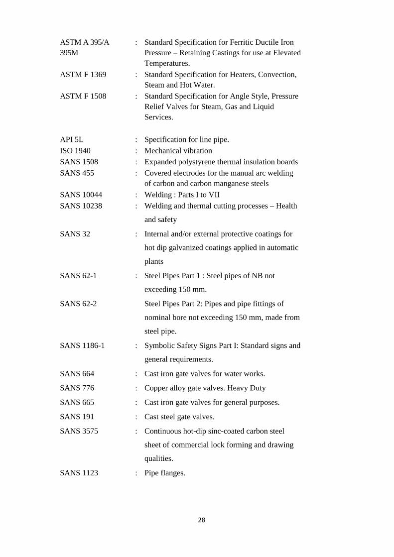
ASTM A 395/A
395M
: Standard Specification for Ferritic Ductile Iron
Pressure – Retaining Castings for use at Elevated
Temperatures.
ASTM F 1369 : Standard Specification for Heaters, Convection,
Steam and Hot Water.
ASTM F 1508 : Standard Specification for Angle Style, Pressure
Relief Valves for Steam, Gas and Liquid
Services.
API 5L : Specification for line pipe.
ISO 1940 : Mechanical vibration
SANS 1508 : Expanded polystyrene thermal insulation boards
SANS 455 : Covered electrodes for the manual arc welding
of carbon and carbon manganese steels
SANS 10044 : Welding : Parts I to VII
SANS 10238 : Welding and thermal cutting processes – Health
and safety
SANS 32 : Internal and/or external protective coatings for
hot dip galvanized coatings applied in automatic
plants
SANS 62-1 : Steel Pipes Part 1 : Steel pipes of NB not
exceeding 150 mm.
SANS 62-2 Steel Pipes Part 2: Pipes and pipe fittings of
nominal bore not exceeding 150 mm, made from
steel pipe.
SANS 1186-1 : Symbolic Safety Signs Part I: Standard signs and
general requirements.
SANS 664 : Cast iron gate valves for water works.
SANS 776 : Copper alloy gate valves. Heavy Duty
SANS 665 : Cast iron gate valves for general purposes.
SANS 191 : Cast steel gate valves.
SANS 3575 : Continuous hot-dip sinc-coated carbon steel
sheet of commercial lock forming and drawing
qualities.
SANS 1123 : Pipe flanges.
29
BS 10 : Specification for flanges and bolting for pipes,
valves and fittings.
BS 2613/70 : The electrical performance of rotating electrical
machinery.
SANS 460 : Copper and copper alloy tubing.
SANS 1067-2 Copper based fittings for copper tubes part
2:capilliary solder fittings