Embed Size (px)
Citation preview

Mechanical Overview of the International X-Ray Observatory
David W. Robinson 301-286-9926, [email protected]
Ryan S. McClelland 301-286-8615, [email protected]
NASA Goddard Space Flight Center Greenbelt, MD 20771
Abstract— The International X-ray Observatory (IXO) is a new collaboration between NASA, ESA, and JAXA which is under study for launch in 2020. IXO will be a large 6600 kilogram Great Observatory-class mission which will build upon the legacies of the Chandra and XMM-Newton X-ray observatories. It combines elements from NASA’s Constellation-X program and ESA’s XEUS program. The observatory will have a 20-25 meter focal length, which necessitates the use of a deployable instrument module. Currently the project is actively trading configurations and layouts of the various instruments and spacecraft components. This paper will provide a snapshot of the latest observatory configuration under consideration and summarize the observatory from the mechanical engineering perspective.
TABLE OF CONTENTS
1. INTRODUCTION.................................................................1 2. IXO CONFIGURATION......................................................2 3. INSTRUMENT MODULE.....................................................3 4. DEPLOYABLE METERING STRUCTURE............................4 5. SPACECRAFT BUS .............................................................6 6. FIXED METERING STRUCTURE ........................................6 7. FLIGHT MODULE ASSEMBLY (FMA) ..............................7 8. LAUNCH VEHICLE INTERFACES.......................................8 9. MECHANISMS ...................................................................9 10. CONCLUSIONS ..............................................................10 REFERENCES ......................................................................10 BIOGRAPHY ........................................................................10
1. INTRODUCTION The International X-ray Observatory (IXO) is a new collaboration between NASA, ESA, and JAXA which is planned to launch in 2021. It combines elements from NASA’s prior Constellation-X program1 and ESA’s XEUS program. IXO will be a large Great-Observatory class mission which will build upon the legacies of the Chandra and XMM-Newton X-ray observatories. Two major improvements in IXO over Chandra and XMM Newton are the high effective area for X-ray photon collecting in the 1 keV to 6 keV range, and a high spectral resolving power achieved with a micro-calorimeter X-ray detector cooled to 50 milliKelvin. The exciting science enabled by IXO
1 1 U.S. Government work not protected by U.S. copyright. 2 IEEEAC paper #1580, Version 1, Updated 2009:01:07.
enabled by IXO includes exploration of black holes, growth and evolution of the largest structures in the universe and cosmic feedback. Details can be found in many other papers and will not be discussed here.1
IXO will have a mass in the neighborhood of 6600 kg and will be approximately 10 meters long and 4 meters in diameter in its launch configuration. It will fly on an Atlas 5 or an Ariane V rocket into an L2 halo orbit. The L2 Lagrange point orbit is approximately 1,500,000 km from Earth on the side opposite the Sun where the gravity of the Earth and Sun are balanced. The main advantages to this orbit are its very stable thermal environment, and the minimal shadowing from the Earth or Moon.
To collect as many photons as possible, IXO will have a 3.2m diameter Flight Mirror Assembly (FMA). Instead of the single large normal incidence primary mirror one finds in optical telescopes, the FMA will consist of nested concentric rings of mirrors which are nearly edge-on to the incoming X-ray photons. X-ray photons glance off the mirror surface at a very shallow angle and are focused 20 meters downstream at the instrument module end of the spacecraft. In the current concept, the FMA has approximately 360 concentric shells of glass, and 14,000 individual pieces of curved glass segments each 0.40 mm thick. Another X-ray focusing concept under development by ESA consists of “micropore” optics. Both concepts present major technological challenges to the IXO mechanical team, particularly in maintaining alignment and ensuring survivability during launch.
A major science driver for the observatory is a long focal length since that enables more photon collecting capability at the higher energy ranges. A focal length of 20 meters was selected for IXO as a reasonable balance between science needs and engineering constraints. No rocket fairing is large enough to fit a 20 meter long observatory, so IXO will have a deployable metering structure between the spacecraft bus and the instrument module.
1
https://ntrs.nasa.gov/search.jsp?R=20090005039 2020-03-26T11:14:25+00:00Z

2. IXO CONFIGURATION When deployed during the cruise to the L2 orbit, IXO will be 23m tall. It is divided into five major assemblies or modules: the Instrument Module (IM), the Deployable Metering Structure, the Spacecraft Bus, the Fixed Metering Structure, and the Optics Module. Each module may be integrated and tested separately at different sites nd then brought together for final integration.
The primary structure of the observatory will be made from carbon fiber reinforced plastic (CFRP) composite materials. The 6.7m long metering structure is planned to be a one-piece composite cylindrical tube with isogrid stiffener ribs. It will be fabricated using advanced fiber placement technology recently developed for wide body airliners and other large aerospace structures.
One of the most interesting mechanical systems of IXO is the triad of deployable 12.1 meter long masts which will extend the instrument module to the focal point. The masts are similar to those used on the international space station solar arrays, and the upcoming Nustar X-ray mission. One challenge for the masts will be pulling up a 4 meter diameter light-tight shroud made of multi-layer insulation between the instrument module and the Flight Mirror
Mirror Assembly. Other mechanisms include the rotational stages for the instruments, launch locks, and a mission unique launch vehicle payload adapter and separation system.
Another challenge in the design is to accommodate the Flight Mirror Assembly which focuses X-rays. The Spectroscopy X-ray Telescope (SXT) Flight Mirror Assembly (FMA) presents unique design challenges due to its 3.2m diameter and support of thousands of 0.4mm thick glass segments arranged in tightly packed concentric rings. The glass segments are assembled into
assembled into wedge shaped modules for integration and testing before the modules are kinematically mounted into a large stiff truss structure to form the FMA.
2. Deployment Module
1. Instrument Module(FIP, MIP, Instruments)
3. Spacecraft Module
4. Optics Module (Flight Mirror Assy)
12.1m
1.0m
6.7m
2.4m
23.8m
1.2m
Node
Focal Plane
20.2m
0.4m
Figure 1
2. Deployment Module
1. Instrument Module(FIP, MIP, Instruments)
3. Spacecraft Module
4. Optics Module (Flight Mirror Assy)
12.1m
1.0m
6.7m
2.4m
23.8m
1.2m
Node
Focal Plane
20.2m
0.4m
Figure 1
When stowed for launch, IXO will be about 10m long and 4 meters in diameter and fit into a medium Atlas 5 or Ariane V fairing.
2
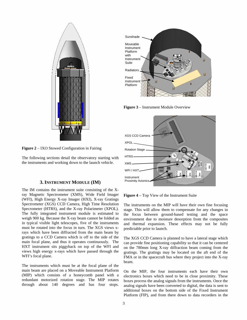
Sunshade Moveable Instrument Platform with Instrument Suite Radiators Fixed Instrument Platform
Figure 2 – IXO Stowed Configuration in Fairing
The following sections detail the observatory starting with the instruments and working down to the launch vehicle.
3. INSTRUMENT MODULE (IM) The IM contains the instrument suite consisting of the X-ray Magnetic Spectrometer (XMS), Wide Field Imager (WFI), High Energy X-ray Imager (HXI), X-ray Gratings Spectrometer (XGS) CCD Camera, High Time Resolution Specrometer (HTRS), and the X-ray Polarimeter (XPOL). The fully integrated instrument module is estimated to weigh 900 kg. Because the X-ray beam cannot be folded as in typical visible light telescopes, five of the instruments must be rotated into the focus in turn. The XGS views x-rays which have been diffracted from the main beam by gratings to a CCD Camera which is off to the side of the main focal plane, and thus it operates continuously. The HXT instrument sits piggyback on top of the WFI and views high energy x-rays which have passed through the WFI’s focal plane.
The instruments which must be at the focal plane of the main beam are placed on a Moveable Instrument Platform (MIP) which consists of a honeycomb panel with a redundant motorized rotation stage. The MIP rotates through about 140 degrees and has four stops.
Figure 3 – Instrument Module Overview
XGS CCD Camera XPOL Rotation Stage HTRS XMS WFI / HXT Instrument Proximity Avionics
Figure 4 – Top View of the Instrument Suite
The instruments on the MIP will have their own fine focusing stage. This will allow them to compensate for any changes in the focus between ground-based testing and the space environment due to moisture desorption from the composites and thermal expansion. These effects may not be fully predictable prior to launch.
The XGS CCD Camera is planned to have a lateral stage which can provide fine positioning capability so that it can be centered on the 780mm long X-ray diffraction beam coming from the gratings. The gratings may be located on the aft end of the FMA or in the spacecraft bus where they project into the X-ray beam.
On the MIP, the four instruments each have their own electronics boxes which need to be in close proximity. These boxes process the analog signals from the instruments. Once the analog signals have been converted to digital, the data is sent to additional boxes on the bottom side of the Fixed Instrument Platform (FIP), and from there down to data recorders in the
3

recorders in the spacecraft bus.
One challenge in the layout of the IM is accommodating the thermal hardware. A 1.4m2 louvered radiator will be installed onto the MIP to reject the heat of the local boxes via constant conductance heat pipes. The instruments may have their own radiators looking out to deep space. The remaining instrument electronics boxes have been located on the underside of the FIP to keep them within the large shroud around the observatory metering structure. The environment inside the shroud is more quiescent. The FIP is a honeycomb panel with embedded heat pipes to transfer heat from the boxes to a radiator which has a view to deep space.
Figure 5 – View of avionics underneath the FIP
A fixed sunshield mounted to the FIP will keep the
4. DEPLOYABLE METERING STRUCTURE The the
instruments in shadow at all times to maintain a very stable thermal environment. Further stabilizing the thermal environment is the requirement that the observatory will stay within +/- 10 degrees roll and +/- 20 degrees pitch of the incoming sunline.
job of the deployable metering structure is to pushstowed instrument module 12.1 meters away from the spacecraft bus to the X-ray focal point. The deployable metering structure consists of the deployment system, a light-tight shroud, baffles, and wire harness between the instruments and the bus. The goal for the deployment system is to place and maintain the instrument module in the focus within +/- 1 mm.
Figure 6 – 3 masts emerging from their stowage canisters
The deployment system is envisioned to be three masts which deploy from canisters located in the spacecraft bus. Three masts are required to maintain the stability of the IM and keep the fundamental resonant frequencies of the deployed spacecraft above 1 Hz. Preliminary analysis showed that the 1st bending mode is above 1.4 Hz and the 1st torsion mode is above 4 Hz. Another analysis showed that jitter from the reaction wheels will not excite these modes and that the displacement of the focal point will be quite small and well within requirements.
12.1m deployment
Figure 7 – The 3-mast system deploys 12.1m
4

Masts of this type are used to deploy the International Space Station solar array wings a distance of 35m. Another example flew on STS-99 in 2000 and deployed a radar topography instrument 60 meters from the shuttle while maintaining extremely tight stability.
The masts fold up inside the canisters for storage and deploy from the canister in a very precise and repeatable manner. As the mast deploys from the canister it forms a repeating series of cubic bays framed by vertical members (longerons), horizontal members (battens), and diagonal crossbraces. The longerons and battens are made of graphite rods and the crossbraces are stainless steel cables. The mass of each mast and canister assembly is estimated at 60 kg. Encoded motors in the canisters ensure that the three masts extend synchronously to deploy the IM.
The wire harness between the IM and the bus is expected to be at least several dozen twisted shielded pairs of wires. The wires will be braided through the battens and longerons in the canister when stowed and will deploy along with the masts. This technique has been successfully employed on several deployable masts in orbit.
Shroud
A shroud is required between the bottom of the IM and the top of the spacecraft bus and around the three masts. This shroud must block stray light from entering the instruments and flooding their detectors. The shroud will consist of multi-layer insulation blankets which are pleated like an accordion or camera bellows. The pleats allow the shroud to be folded up into a channel located on top of the spacecraft bus for stowage prior to deployment.
Figure 8 – IXO’s shroud and baffles
To reduce the number of micrometeorite penetrations causing light leaks, the shroud consists of two concentric blankets separated by 10 cm to form a “Whipple shield.” Each blanket will be constructed of 5-10 layers of ¼-mil aluminized Mylar and Dacron scrim cloth with thicker inner and outer layers. The mass of the shroud depends on the number and thickness of layers required but is expected to the about 150 kg. The blankets will maintain a steady-state thermal environment inside the enclosed volume which will minimize thermal expansion or contraction from the masts to help meet the observatory’s stability requirements.
Concentric MLI blanketsIn Stowage Channel
10 cm
Stowed Configuration
Deployed Configuration
Concentric MLI blanketsIn Stowage Channel
10 cm
Stowed Configuration
Deployed Configuration
Figure 9 – Concentric accordian shrouds in stowage channel
A small-scale prototype of this accordion-shaped blanket was fabricated at NASA Goddard which demonstrated that IXO’s 12.1m shroud can be folded and stowed into a stack only about 20 cm tall.
Figure 10 – Scale model of accordion-style shroud
Baffles
As seen in Figure 8, several baffles are also required inside the shroud to further block stray X-ray photons. These baffles are
5
thin sheets of Tantalum foil on a film backer. They match the diameter of the shroud (~3.9m diameter) with cutouts that closely match the size of the X-ray beams passing through. The baffles will be attached to the interior of the shroud and deploy along with the shroud.
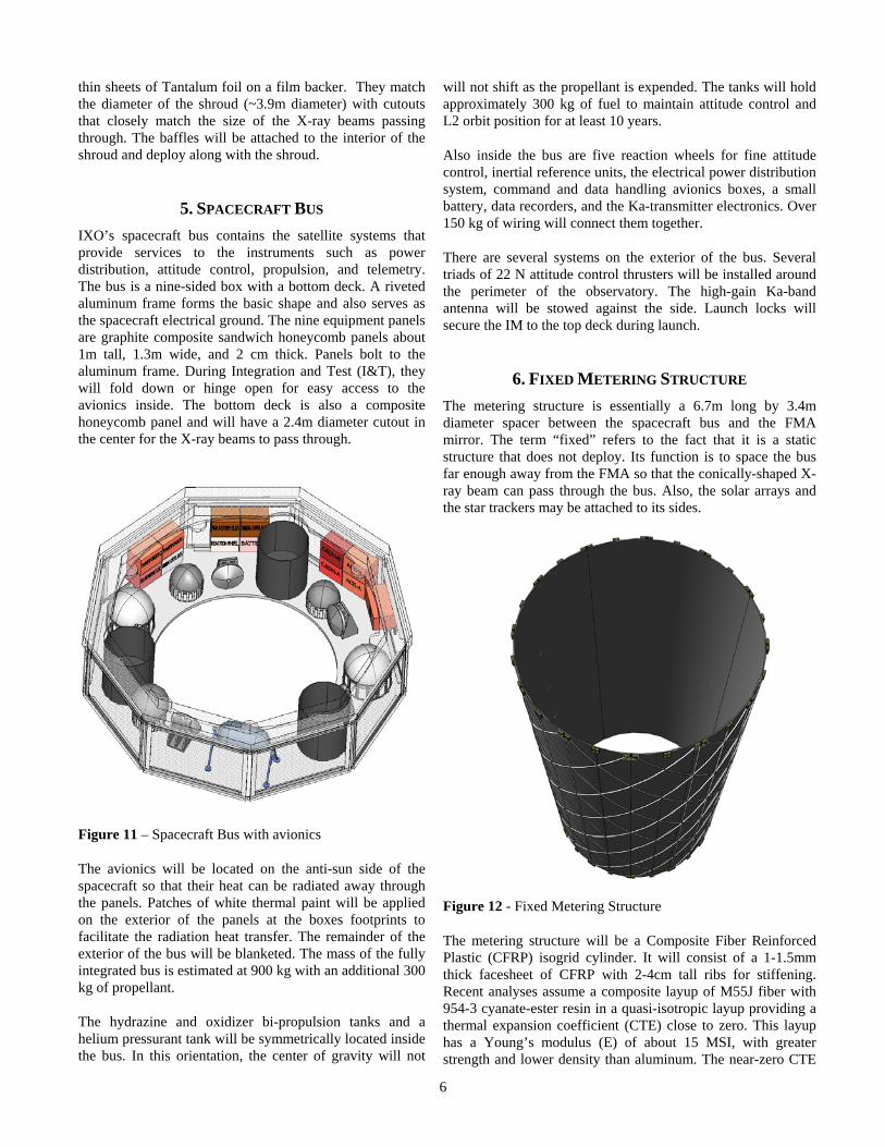
5. SPACECRAFT BUS IXO’s spacecraft bus contains the satellite systems that provide services to the instruments such as power distribution, attitude control, propulsion, and telemetry. The bus is a nine-sided box with a bottom deck. A riveted aluminum frame forms the basic shape and also serves as the spacecraft electrical ground. The nine equipment panels are graphite composite sandwich honeycomb panels about 1m tall, 1.3m wide, and 2 cm thick. Panels bolt to the aluminum frame. During Integration and Test (I&T), they will fold down or hinge open for easy access to the avionics inside. The bottom deck is also a composite honeycomb panel and will have a 2.4m diameter cutout in the center for the X-ray beams to pass through.
Figure 11 – Spacecraft Bus with avionics
The avionics will be located on the anti-sun side of the spacecraft so that their heat can be radiated away through the panels. Patches of white thermal paint will be applied on the exterior of the panels at the boxes footprints to facilitate the radiation heat transfer. The remainder of the exterior of the bus will be blanketed. The mass of the fully integrated bus is estimated at 900 kg with an additional 300 kg of propellant.
The hydrazine and oxidizer bi-propulsion tanks and a helium pressurant tank will be symmetrically located inside the bus. In this orientation, the center of gravity will not
will not shift as the propellant is expended. The tanks will hold approximately 300 kg of fuel to maintain attitude control and L2 orbit position for at least 10 years.
Also inside the bus are five reaction wheels for fine attitude control, inertial reference units, the electrical power distribution system, command and data handling avionics boxes, a small battery, data recorders, and the Ka-transmitter electronics. Over 150 kg of wiring will connect them together.
There are several systems on the exterior of the bus. Several triads of 22 N attitude control thrusters will be installed around the perimeter of the observatory. The high-gain Ka-band antenna will be stowed against the side. Launch locks will secure the IM to the top deck during launch.
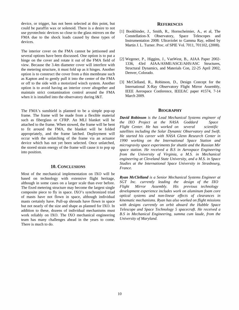
6. FIXED METERING STRUCTURE The metering structure is essentially a 6.7m long by 3.4m diameter spacer between the spacecraft bus and the FMA mirror. The term “fixed” refers to the fact that it is a static structure that does not deploy. Its function is to space the bus far enough away from the FMA so that the conically-shaped X-ray beam can pass through the bus. Also, the solar arrays and the star trackers may be attached to its sides.
Figure 12 - Fixed Metering Structure
The metering structure will be a Composite Fiber Reinforced Plastic (CFRP) isogrid cylinder. It will consist of a 1-1.5mm thick facesheet of CFRP with 2-4cm tall ribs for stiffening. Recent analyses assume a composite layup of M55J fiber with 954-3 cyanate-ester resin in a quasi-isotropic layup providing a thermal expansion coefficient (CTE) close to zero. This layup has a Young’s modulus (E) of about 15 MSI, with greater strength and lower density than aluminum. The near-zero CTE
6

zero CTE helps to maintain the focal length of the observatory in various thermal environments during ground testing and on orbit. The high Young’s Modulus helps the observatory meet the 8 Hz 1st bending mode requirement imposed by the launch vehicle.
The isogrid concept, also known as an Advanced Grid Stiffened structure (AGS), was chosen since it provides a higher stiffness to weight ratio to other types of cylindrical design approaches such as skin-stringer, stiffened skin, and semi-monocoque. Recent efforts, such as an Air Force program for the Minotaur fairing, have been successful in making AGS structures from CFRP that are lighter weight and have lower parts count than previous designs2. The mass of IXO’s metering structure is estimated to be 290 kg, not including metallic fittings or inserts.
Manufacturing of the metering structure is anticipated to be via a large automatic fiber placement machine. The structure is made by laying CFRP prepreg tape or cloth onto a mandrel. After all the prepreg is layed down on the mandrel, the whole assembly is moved into an autoclave for curing. After curing the piece is removed from the mandrel and is ready for further processing such as installing inserts or bonding fittings.
Just a few years ago, structures this size were considered too large for automated machinery, but recent advances have now made such structures routine. Large airplane fuselages are now being made by automatic fiber placement machines in factories in the U.S. and Europe. The cost of mandrel fabrication has also been greatly reduced as well.
There is much work to be done to optimize the structure in terms of the thickness of the facesheet, and geometry of the ribs. Another task will be to find the best CFRP layup. There may be other fiber-resin systems available that can provide higher stiffness to weight ratios and meet all the other requirements.
Choosing the length of the metering structure is a balance between several factors. One factor is the desire to keep the center of gravity of the spacecraft low to stay within the CG height limitation of the payload adapter and to minimize launch loads. On one hand, the deployable system is lighter per meter of length than the fixed metering structure so there is a desire to maximize the mast length and minimize the fixed metering structure length. On the other hand, the deployable mast system is less stiff than the fixed metering structure and must have a high enough bending and torsion resonant mode to satisfy the attitude control system and the instrument pointing requirements. This argues for a short deployed length. Lastly, the spacecraft bus must be large enough allow the X-ray beam to pass through it. The X-ray beam exits the FMA with a diameter of 3.2m and tapers to ~10cm
~10cm diameter at the focal plane 20m away. The spacecraft bus requires about 80cm of “wall space” all around the beam to accommodate the propulsion tanks and avionics. A maximum bus diameter of 4m was selected because this fits into the static envelope of the Atlas 5 fairing (4.57m diameter) with a little margin. Considering the 80cm distance needed from each panel, the size of the X-ray hole can be 2.4m diameter. At this size, the length of the fixed metering structure works out to 6.7m.
Titanium fittings will be bonded to the top of the metering structure to interface to the spacecraft bus bottom deck. Likewise, fittings bonded to the bottom of the metering structure will interface to the spacecraft adapter ring. Titanium (usually Ti-6Al-4V) is often used for fittings on composite structures because of its strength and relatively low CTE which is compatible with the near-zero CTE of the CFRP. Because of the low bearing strength and thin-walls of most CFRP structures, it is not advisable to thread or bolt through them directly in a heavily loaded joint.
7. FLIGHT MIRROR ASSEMBLY (FMA) The FMA is the huge x-ray collecting and focusing device for the X-ray telescope. It weighs about 1700 kg and is arguably the largest design driver of the observatory. Another paper in this conference discusses the FMA design in detail3. The FMA’s Wolter-I x-ray telescope optical design consists about 14,000 0.4mm thick glass mirror segments densely packed into a 3.2m diameter and supported with micron level accuracy and stability.
Figure 13 – Flight Module Assembly and spacecraft adapter.
A research and development program at NASA Goddard Space Flight Center has been in place for several years to determine the best way to form the glass mirrors and align them into a flight-like structure. The current concept involves placing flat glass sheets over a highly polished and figured mandrel and
7

mandrel and heating them to ~600C to the point that the glass slumps onto the mandrel and takes its shape. After cooling, the glass is removed, held in some fashion to reduce the effects of gravity, and bonded at the edges to a mirror module structure.
The primary structure of the FMA looks like a wagon wheel. It is currently envisioned to have 24 spokes which intersect at a central hub. Around the spokes are three rings. Modules will be kinematically mounted to the wagon wheel structure.
Figure 14 – One FMA primary Structure concept
The mirror module is the basic building block of the FMA. A module is a wedge shaped housing which contains about 240 glass segments and weighs about 20 kg. The current FMA design contains 24 modules around the FMA perimeter to form the outer ring. There are another 24 modules in the middle ring and 12 in the inner ring.
The FMA will be fastened to the spacecraft adapter ring in at least 6 points. The spacecraft adapter ring is essentially an aluminum cylinder with flanges on top and bottom. Shims and/or flexures will be used between the FMA and the adapter mounting flange to ensure that the FMA does not warp and come out of alignment when the bolts are torqued down, as well as relieve misalignments in the FMA caused by thermal gradients on the spacecraft adapter.
8. LAUNCH VEHICLE INTERFACES The FMA and metering structure will be attached to the top flange of a 43 cm tall, 3.4m diameter aluminum cylinder called the spacecraft adapter. The bottom flange of the adapter is the interface to a separation ring which contains a mission-unique separation system. The separation ring is
separation ring is another 43 cm by 3.4m diameter aluminum cylinder with flanges on the top surface where the separation system secures the spacecraft adapter for launch. The separation ring is bolted to a 3302 Truss Adapter which is fastened to the top of the Centaur upper stage. The truss adapter is provided by Atlas.
Launch Vehicle Upper Stage
Figure 15: IXO on the 3302 Truss Adapter
The diameter of the spacecraft adapter and separation ring is driven by the FMA diameter of 3.3m. This is too large to allow IXO to use a standard payload adapter and separation system provided by Atlas. It could be possible to make an inverted frustum (truncated cone) adapter from the spacecraft to the largest standard size payload adapter (1.6 m diameter) but its smaller size obscures the aperture of the FMA. Therefore, the frustum adapter would have to be jettisoned in orbit which is an added complication and weight penalty. Another problem which rules out the 1.6m adapter is that IXO exceeds its center of gravity height limitation.
IXO’s mission-unique separation system could be either a Marmon clamp-band or a set of separation nuts and springs. Since no clamp-band of that size is known to be qualified for flight, currently IXO is planning to use a set of 8 pyrotechnic-actuated separation bolts with push-off springs to achieve the separation.
Truss Adapter
Large diameter truss adapters are offered by the Atlas Mission Planner’s Guide as an option for heavy spacecraft or those with a very high center of gravity. The 3302 truss adapter is nearly the perfect size for the current IXO configuration. To the best of our knowledge, the 3302 truss adapter has not yet been qualified for flight.
8

Figure 16 – 3302 Truss Adapter concept model
The center of gravity height limitation on the 3302 truss adapter is at 5.7m above the standard interface plane. IXO currently has a stowed center of gravity of 4.6m which is within the capability.
For the Ariane V launch vehicle option, a different payload adapter will be required. The current plan is to use a derivative of ESA’s Separation and Distancing Module (SDM) which was used on the Jules Verne Automated Transfer vehicle. The SDM is essentially a large cylindrical ring of diameter 3.94m in diameter. It interfaces to the top of the Ariane V’s upper stage. Regardless of the launch vehicle that is ultimately chosen, it appears that a mission unique payload adapter will be required for IXO.
9. MECHANISMS There are many mechanisms required for IXO to achieve mission success. Beyond the mechanisms internal to the instruments, there are the following mechanisms starting at the instrument end of IXO:
• Launch locks for the Fixed Instrument Platform to the Bus. Expected to be pyrotechnic-actuated separation nuts.
• Rotation stage for the Moveable Instrument Platform to position the XMS and WFI in the focus. The motor is expected to have primary and backup stepper motors with a gearbox and engagement mechanisms.
Figure 17 – Rotation Stage concept
• Focus mechanisms for XMS and WFI with a range of motion of +/- 1.5cm.
• Lateral positioning mechanisms for the XGS camera box with a range of motion of ~ +/- 1cm.
• Deployable Masts (discussed earlier).
• High Gain Ka-Band Antenna with azimuth and elevation gimbals to maintain pointing at the Deep Space Network ground antennas.
• Two solar array wings. Standard commercial arrays and pyrotechnic separation systems are planned.
• Launch vehicle separation system (discussed earlier)
• FMA internal cover.
• FMA external cover, to be jettisoned.
• FMA deployable sunshield
Mechanisms will be single failure tolerant if possible.
FMA Covers and Sunshield
The FMA will have covers on the fore and aft ends during Integration and Test (I&T) to reduce the contamination by particulates and condensation of offgassed substances, particularly silicones, onto the mirrors. The FMA will be purged by ultra-pure nitrogen during I&T and both covers must be able to withstand about 0.1 psi of differential pressure caused by the purge and launch depressurization. After launch and once the outgassing and moisture desorption of IXO has diminished sufficiently, the FMA covers will be removed. The exterior cover will be jettisoned by springs. The actuation
9
REFERENCES device, or trigger, has not been selected at this point, but could be paraffin wax or solenoid. There is a desire to not use pyrotechnic devices so close to the glass mirrors on the FMA due to the shock loads caused by these types of devices.
[1] Bookbinder, J., Smith, R., Hornscheimier, A., et al, The Constellation-X Observatory, Space Telescopes and Instrumentation 2008: Ultraviolet to Gamma Ray, edited by Martin J. L. Turner. Proc. of SPIE Vol. 7011, 701102, (2008).
The interior cover on the FMA cannot be jettisoned and several options have been discussed. One option is to put a hinge on the cover and rotate it out of the FMA field of view. Because the 3.4m diameter cover will interfere with the metering structure, it must fold up as it hinges. Another option is to construct the cover from a thin membrane such as Kapton and to gently pull it into the center of the FMA or off to the side with a motorized winch system. Another option is to avoid having an interior cover altogether and maintain strict contamination control around the FMA when it is installed into the observatory during I&T.
[2] Wegener, P., Higgins, J., VanWest, B., AIAA Paper 2002-1336, 43rd AIAA/ASME/ASCE/AHS/ASC Structures, Structural Dynamics, and Materials Con, 22-25 April 2002, Denver, Colorado.
[3] McClelland, R., Robinson, D., Design Concept for the International X-Ray Observatory Flight Mirror Assembly, IEEE Aerospace Conference, IEEEAC paper #1574, 7-14 March 2009.
BIOGRAPHY The FMA’s sunshield is planned to be a simple pop-up frame. The frame will be made from a flexible material such as fiberglass or CFRP. An MLI blanket will be attached to the frame. When stowed, the frame will be bent to fit around the FMA, the blanket will be folded appropriately, and the frame latched. Deployment will occur with the unlatching of the frame via an actuator device which has not yet been selected. Once unlatched, the stored strain energy of the frame will cause it to pop up into position.
David Robinson is the Lead Mechanical Systems engineer of the IXO Project at the NASA Goddard Space Flight Center. He has worked on several scientific satellites including the Solar Dynamic Observatory and Swift. He started his career with NASA Glenn Research Center in 1990 working on the International Space Station and microgravity space experiments for shuttle and the Russian Mir space station. He received a B.S in Aerospace Engineering from the University of Virginia, a M.S. in Mechanical engineering at Cleveland State University, and a M.S. in Space Studies at the International Space University in Strasbourg, France.
10. CONCLUSIONS Most of the mechanical implementation on IXO will be based on technology with extensive flight heritage, although in some cases on a larger scale than ever before. The fixed metering structure may become the largest single composite piece to fly in space. IXO’s synchronized triad of masts have not flown in space, although individual masts certainly have. Pull-up shrouds have flown in space but not nearly of the size and shape as planned for IXO. In addition to these, dozens of individual mechanisms must work reliably on IXO. The IXO mechanical engineering team has many challenges ahead in the years to come. There is much to do.
Ryan McClelland is a Senior Mechanical Systems Engineer at SGT Inc. currently leading the design of the IXO Flight Mirror Assembly. His previous technology development experience includes work on aluminum foam core optical systems and non-linear effects of clearances in kinematic mechanisms. Ryan has also worked on flight missions with designs currently on orbit aboard the Hubble Space Telescope and Space Technology 5 spacecraft. He received a B.S in Mechanical Engineering, summa cum laude, from the University of Maryland.
10