Embed Size (px)
Citation preview
T R A N S M I SS I O N S
Mechanical Power Transmission

Agriculture
Automotive
Construction
Industrial
Motor Sport
“We are proud to be a European manufacturer; it is a privilege
to supply our products to some of the world’s most prestigious
original equipment manufacturers in the Agricultural, Automotive,
Construction, Industrial and Motor Sport sectors”.
“Our distributor network is vital to the continued global growth
of the DUNLOP brand and our valued distributor partners form the
perfect link between manufacturer and end user”.
“Our commitment to our staff, our customers and the environment
is of paramount importance to our company, we will continue to
develop our organisational skills to further enhance our company’s
potential, to engage in sustainable practices and anticipate the
needs and expectations of our customers”.
“We love our products”.
Ray Mifsud, Managing Director.
WE LOVE OURPRODUCTS.
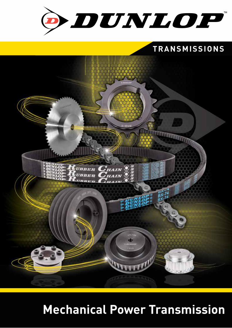
Contact us
+44 (0)1233 663340
+44 (0)1233 664440
www.dunlopbtl.com
Dunlop BTL Ltd - AshfordEuropean Distribution Centre
MPT House, Brunswick RoadCobbs Wood Industrial EstateAshford, KentTN23 1EL , United Kingdom
Manufacturing Facilities
UNITED KINGDOM
FRANCE
GERMANY
ITALY
SPAIN
POLAND
CZECH REPUBLIC
SLOVAKIA
SERBIA
CHINA
USA
Dunlop BTL Ltd - ConsettUK Manufacturing Centre
Unit 46, Werdolh Way,No 1 Industrial Estate, Consett, County Durham DH8 6SZ , United Kingdom
Manufacturing Facilities, Consett, Co. Durham UKUnit 46, Werdolh Way,
No 1 Industrial Estate,
Consett, County Durham
DH8 6SZ , United Kingdom
European Distribution Centre, Ashford, Kent UKMPT House, Brunswick Road
Cobbs Wood Industrial Estate
Ashford, Kent
TN23 1EL , United Kingdom
“We are proud to be a European manufacturer; it is a
privilege to supply our products to some of the world’s
most prestigious original equipment manufacturers in the
Agricultural, Automotive, Construction, Industrial and
Motor Sport sectors”.
“Our distributor network is vital to the continued global
growth of the DUNLOP brand and our valued distributor
partners form the perfect link between manufacturer
and end user”.
“Our commitment to our staff, our customers and
the environment is of paramount importance to our
company, we will continue to develop our organisational
skills to further enhance our company’s potential, to engage
in sustainable practices and anticipate the needs and
expectations of our customers”.
“At Dunlop BTL we love our products”.
Ray Mifsud, Managing Director.
English
Español
Italiano
Deutsch
Français
Nederlands
Polskie
Engineering Data 243 Datos de ingeniería • Dati ingegneristici • Technische gegevens
Données d’ingénierie • Technische gegevens • Dane Inżynieria
Tensioner Arms 247 Brazos de tensor • Braccia di tenditore • Spanner-Arme
Bras tendeur • Spanner wapens • ramiona napinaczy
Idler Sprocket Sets 248 Sistemas de rueda dentada intermedia • Pacchi pignoni folli
Spannrolle Ritzelpakete • Ensembles de pignon pignon fou
Idler tandwiel sets • zestawy łańcuchowe napinające
Idler Roller Pulley Sets 249 Sistemas de polea rodillo rodillos • Idler rulli puleggia
Spannrolle Riemenscheibe Rollensätze • Ensembles de poulie tendeurs rouleau
Idler roller katrol sets • Zestawy rolką pośredniczącą
Motor Bases 250 Bases del motor • Slitte • Motorbasen • Bases de moteur
motor bases • Bazy silnikowe
Shaft Collar Metric and Imperial 251 Collar del eje métrico e imperial • Con collare metrico e imperiale
Wellen-Kragen metrisch und kaiserlich • Collier d’arbre métrique et impérial
Shaft Collar Metric en Imperial • Wał Collar Metric i Imperial
C H A I N & P U L L E Y T E N S I O N E R S

243www.dunlopbtl.com
ENGINEERING DATA
TENSIONING TECHNOLOGY
INSTALLATION
Chain & V-Belt TensioningRoller chains are power transmission components with positive transmission which, by virtue of their design are subject, depending on quality, to elongation as a result of wear of 1 to 3% of their total length. In spite of this elongation, due to aging, a roller chain transmits the occurring torques effectively providing it is periodically re-tensioned. Without tension adjustment, the slack side of the chain becomes steadily longer, oscillates and reduces the force transmitting wrap angle of the chain on the sprockets.
The chain no longer runs smoothly off the teeth of the sprockets, producing uneven running of the entire drive and supporting wear. The service life of the chain drive can be extended considerablyby the use of an automatic chain tension adjuster. The tensioning element prevents the slack side of the chain from ‘sagging’ or ‘slapping’ by its automatic operation and very wide tensioning range for compensating this given elongation.
The DUNLOP tensioning element is based on the rubber spring principle. According to applicationit is supplemented with the appropriate idler sprocket for chain drives or with a belt roller pulley in belt tensioner applications.
Pre-tensioningWith the tensioning element the necessary travel and simultaneously the corresponding initial tension force can be accurately adjusted by a torsion angle scale and indicating arrow. Excessive initial pre-tensioning of the chain should be avoided in order to reduce the tensile force and surface pressure on the links.
Vibration DampingThe DUNLOP tensioning element, based on a system of rubber springs, absorbs considerably the chain vibration due to internal molecular friction in the rubber inserts. The rubber spring effectively absorbs the vibrations, resulting from the polygon effect, which also positively influences the noise level of the complete chain drive.
The idler sprocket is installed in arm position ‘normal’ or ‘hard’ in the required position andsecured with the supplied nuts.
The laterally adjustable bearing on the thread permits simple and rapid adjustment of the idler sprocket to the chain track. The central fixing of the tensioning element with a single screw savesa great deal of time in installation. In addition, only one fixing hole is required on the ‘machine side’.
On smooth, clean and torsionally rigid surfaces the resistance of the frictional contact betweenthe tensioner housing and the machine element is a multiple of the maximum initial tensioning torque at 30˚.
ENGINEERING DATA
TENSIONER TYPE SE
GENERAL INFORMATION
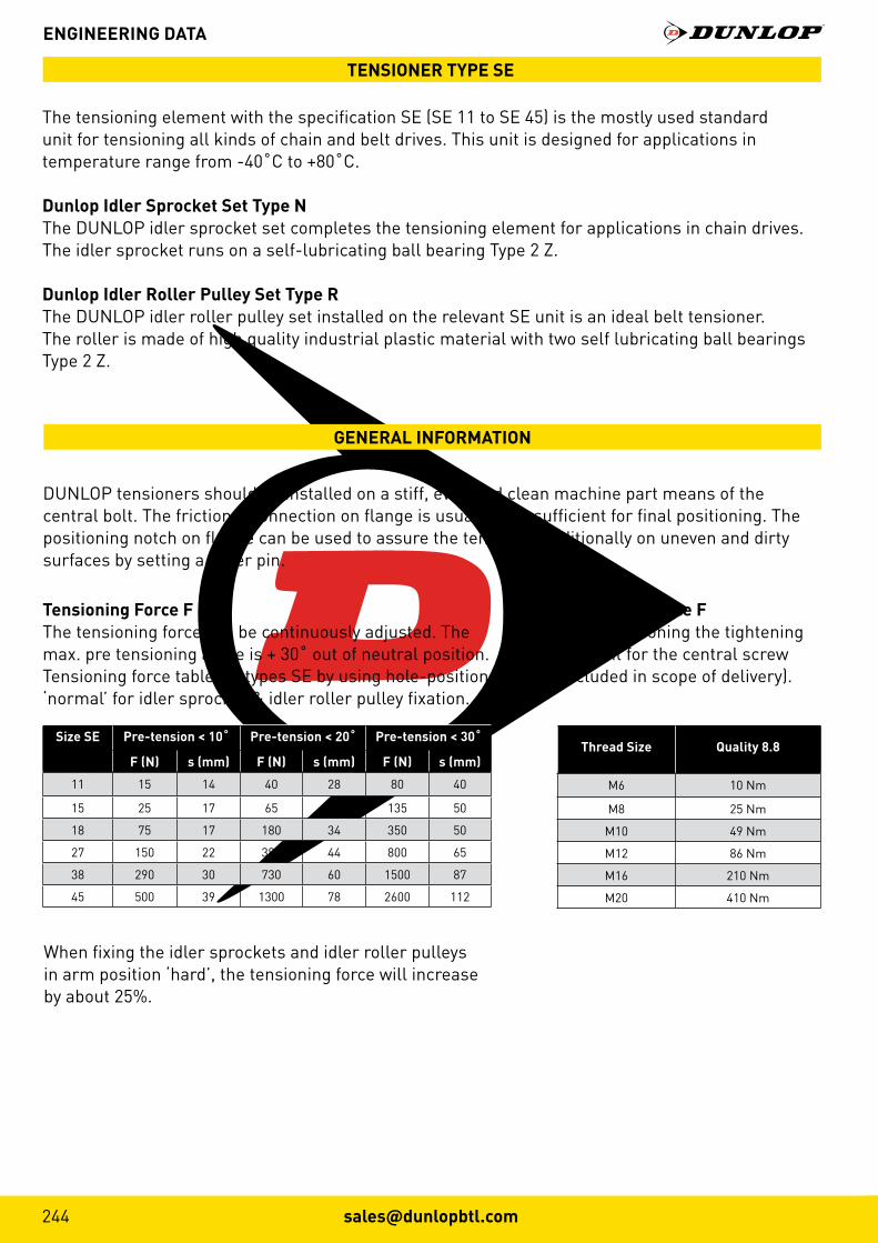
The tensioning element with the specification SE (SE 11 to SE 45) is the mostly used standard unit for tensioning all kinds of chain and belt drives. This unit is designed for applications in temperature range from -40˚C to +80˚C.
Dunlop Idler Sprocket Set Type NThe DUNLOP idler sprocket set completes the tensioning element for applications in chain drives. The idler sprocket runs on a self-lubricating ball bearing Type 2 Z.
Dunlop Idler Roller Pulley Set Type RThe DUNLOP idler roller pulley set installed on the relevant SE unit is an ideal belt tensioner.The roller is made of high quality industrial plastic material with two self lubricating ball bearings Type 2 Z.
DUNLOP tensioners should be installed on a stiff, even and clean machine part means of thecentral bolt. The frictional connection on flange is usually fully sufficient for final positioning. The positioning notch on flange can be used to assure the tensioner additionally on uneven and dirty surfaces by setting a roller pin.
Tensioning Force FThe tensioning force can be continuously adjusted. The max. pre tensioning angle is + 30˚ out of neutral position. Tensioning force table for types SE by using hole-position ‘normal’ for idler sprocket & idler roller pulley fixation.
Tensioning Force FTable mentioning the tighteningmoment for the central screw(included in scope of delivery).
When fixing the idler sprockets and idler roller pulleys in arm position ‘hard’, the tensioning force will increase by about 25%.
Size SE Pre-tension < 10˚ Pre-tension < 20˚ Pre-tension < 30˚
F (N) s (mm) F (N) s (mm) F (N) s (mm)
11 15 14 40 28 80 40
15 25 17 65 34 135 50
18 75 17 180 34 350 50
27 150 22 380 44 800 65
38 290 30 730 60 1500 87
45 500 39 1300 78 2600 112
Thread Size Quality 8.8
M6 10 Nm
M8 25 Nm
M10 49 Nm
M12 86 Nm
M16 210 Nm
M20 410 Nm

245www.dunlopbtl.com
ENGINEERING DATA
Mounting Instructions
12
3
Normal PositioningThe DUNLOP tensioning elements are always positioned onthe slack side of the chain. They should be fitted as close aspossible to the big wheel and hide the chain from the outer side. The ideal positioning of the tensioning arm is nearly parallel to the chain drive.
Reversible Chain DrivesThe tensioning elements must be placed on both sides of the chain. Due to the reversible function there results a much higher pressure on the load side than on the slack side of the chain. It is therefore advised to use oversized tensioningelements and a pretension angle of max 15˚.
Chain EngagementAt least 3 teeth of the idler sprocket must engage into the roller chain when tensioning the chain for the first time. The minimum number of engaged sprocket teeth between the tensioning wheel and chain is 3.
MountingThe chain tensioner must be adjusted in the axial and angulardirection. The tensioning area should be nearly in parallelposition to the chain and in the direction of the chain’s drive.In case the chain drives are extremely long it is possible to fitseveral chain tensioners in order to obtain better tensioning and compensation.
V-Belt Tensioner - Outer RollerPlease refer to the instructions of the belt manufacturer forfurther information on the belt structure when mounting our DUNLOP belt tensioning elements with flat rollers on the back of the belt. Inner or outer tension rollers must be positioned as far away as possible from the next V-Belt pulley the belt is guided to.
V-Belt Tensioner - Inner Grooved PulleysV-Belt pulleys can be mounted as inner rollers at any position on the slack side of the V-Belt (for drives with long axial distances and a high level of vibration we recommend to use pulleys with deep grooves).

ACCESSORIES
INSTRUCTIONS FOR BELT DRIVES
V-Belt Type
Width(mm)
Height(mm)
Diam. of smaller pulley (mm)
Initial operationtest-force FI** (N)
Initial operationtest-force Fº** (N)
Size SE* (without SE-W and SE-B)
1 Belt 2 Belt 3 Belt 4 Belt 5 Belt
SPZ, SPZX 10 8 56-71 20 16 11 18 18 18 18
75-90 22 18 11 18 18 18 27
95-125 25 20 15 18 18 18 27
≥ 125 28 22 15 18 18 27 27
SPA, SPAX 13 10 80-100 28 22 15 18 18 27 27
106-140 38 30 15 18 27 27 27
150-200 45 36 18 18 27 27 27
≥ 200 50 40 18 18 27 27 38
SPB, SPBX 16 13 112-160 50 40 18 18 27 27 38
170-224 62 50 18 27 27 38 38
236-355 77 62 18 27 38 38 38
≥ 355 81 65 18 27 38 38 38
SPC, SPCX 22 18 224-250 87 70 18 27 38 38 38
265-355 115 92 27 38 38 45 45
≥ 375 144 115 27 38 38 45 45
Z, ZX 10 6 56-100 5-7.5 11 11 11 15 15
A, AX 13 8 80-140 10-15 11 15 18 18 18
B, BX 17 10 125-200 20-30 15 18 18 27 27
C, CX 22 12 200-400 40-60 18 27 27 38 38
D, DX 32 19 355-600 70-105 18 27 38 38 45
Selection of the adequate DUNLOP Tensioner sizeSelection table mentioning the most conventional V-Belt types.
*General basic selection criteria:F Resulting tensioning force by a pre-tension angle of 20˚.F| Initial operation test-force according guidelines of the belt manufacturer.z Quantity of belts in drive.2 Multiplier for the compensation of belt slippage and/or of centrifugal force generated on belt strands.
**required test-force for belt deflection of 16mm per 1000mm of centre distance. The relevantdeflection by shorter or longer centre distance has to be interpolated accordingly.
F = FI · z · 2

247www.dunlopbtl.com
Part No. D E G H J1 J2 K L M N O P T U Weight (kg)
SE 11 35 51 5 M6 80 60 20 90 20 22 6 8 8.5 16.5 0.2
SE 15 45 64 5 M8 100 100 25 112.5 25 30 8 8.5 10.5 20.8 0.4
SE 18 58 79 7 M10 100 100 30 115 30 35 10.5 8.5 10.5 25.3 0.6
SE 27 78 108 8 M12 130 130 50 155 40 52 15 10.5 12.5 34.3 1.7
SE 38 95 140 10 M16 175 175 60 205 40 66 15 12.5 20.5 42.0 3.6
SE 45 115 200 12 M20 225 225 70 260 50 80 18 12.5 20.5 52.0 6.4
TENSIONER DEVICES
BELT AND CHAIN TENSIONERSDescriptionTensioning devices SE are available for both roller chain and V-Belt applications.
A range of idler sprockets to suit standard roller chain pitch sizes from O6B-1 to 24B-1 are available.
A range of idler roller pulleys are also available to suit standard V and wedge belt sections from Z/SPZ to C/SPC. Both designs have 2Z bearings fitted to the bore.
TENSIONERS
TENSIONER ARM TYPE SE
+1-0.5
+1-0.5
+1.5-0.5
+2-0.5
+2-0.5
+3-1
Rollerchain Part No. Number of Teeth
W L Torque hex nut 0.5d (Nm)
Adjusting Range Track R
SizeSE
Weight(kg)
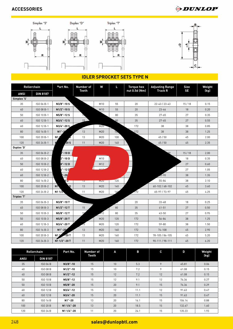
ANSI DIN 8187Simplex ‘S’
35 ISO 06 B-1 N3/8”-10 S 15 M10 55 20 22-43 / 23-43 15 / 18 0.15
40 ISO 08 B-1 N1/2”-10 S 15 M10 55 20 23-44 18 0.20
50 ISO 10 B-1 N5/8”-12 S 15 M12 80 35 27-65 27 0.35
60 ISO 12 B-1 N3/4”-12 S 15 M12 80 35 27-65 27 0.55
60 ISO 12 B-1 N3/4”-20 S 15 M20 100 172 38 38 0.85
80 ISO 16 B-1 N1”-20 S 13 M20 100 172 38 38 1.25
100 ISO 20 B-1 N1 1/4”-20 S 13 M20 100 172 45 / 50 45 2.00
120 ISO 24 B-1 N1 1/2”-20 S 11 M20 140 172 45 / 50 45 2.35
Duplex ‘D’
35 ISO 06 B-2 N3/8”-10 D 15 M10 55 20 27-39 / 28-39 15 / 18 2.00
40 ISO 08 B-2 N1/2”-10 D 15 M10 55 20 30-37 18 0.35
50 ISO 10 B-2 N5/8”-12 D 15 M12 80 35 36-57 27 0.60
60 ISO 12 B-2 N3/4”-12 D 15 M12 80 35 37-56 27 1.05
60 ISO 12 B-2 N3/4”-20 D 15 M20 120 172 50-90 38 1.35
80 ISO 16 B-2 N1”-20 D 13 M20 120 172 55-84 38 2.10
100 ISO 20 B-2 N1 1/4”-20 D 13 M20 140 172 60-102 / 68-102 45 3.60
120 ISO 24 B-2 N1 1/2”-20 D 11 M20 140 172 65-97 / 73-97 45 4.25
Triplex ‘T’
35 ISO 06 B-3 N3/8”-10 T 15 M10 70 20 33-48 18 0.25
40 ISO 08 B-3 N1/2”-12 T 15 M12 80 35 41-51 27 0.50
50 ISO 10 B-3 N5/8”-12 T 15 M12 80 35 43-50 27 0.95
50 ISO 10 B-3 N5/8”-20 T 15 M20 120 172 56-84 38 1.25
60 ISO 12 B-3 N3/4”-20 T 15 M20 120 172 59-80 38 1.50
80 ISO 16 B-3 N1”-20 T 13 M20 160 172 74-108 45 2.90
100 ISO 20 B-3 N1 1/4”-20 T 13 M20 160 172 78-105 / 86-105 45 5.20
120 ISO 24 B-3 N1 1/2”-20 T 11 M20 160 172 90-111 / 98-111 45 6.20
ACCESSORIES
IDLER SPROCKET SETS TYPE N
Rollerchain Part No. Number of Teeth
A B C D Weight(kg)
ANSI DIN 8187
35 ISO 06 B N3/8”-10 15 10 5.3 9 45.81 0.06
40 ISO 08 B N1/2”-10 15 10 7.2 9 61.08 0.15
40 ISO 08 B N1/2”-12 15 12 7.2 12 61.08 0.15
50 ISO 10 B N5/8”-12 15 12 9.1 12 76.36 0.27
50 ISO 10 B N5/8”-20 15 20 9.1 15 76.36 0.29
60 ISO 12 B N3/4”-12 15 12 11.1 12 91.63 0.47
60 ISO 12 B N3/4”-20 15 20 11.1 15 91.63 0.47
80 ISO 16 B N1”-20 13 20 16.1 15 106.14 0.88
100 ISO 20 B N1 1/4”-20 13 20 18.5 15 132.67 1.60
120 ISO 24 B N1 1/4”-20 11 20 24.1 15 135.23 1.93
249www.dunlopbtl.com
ACCESSORIES
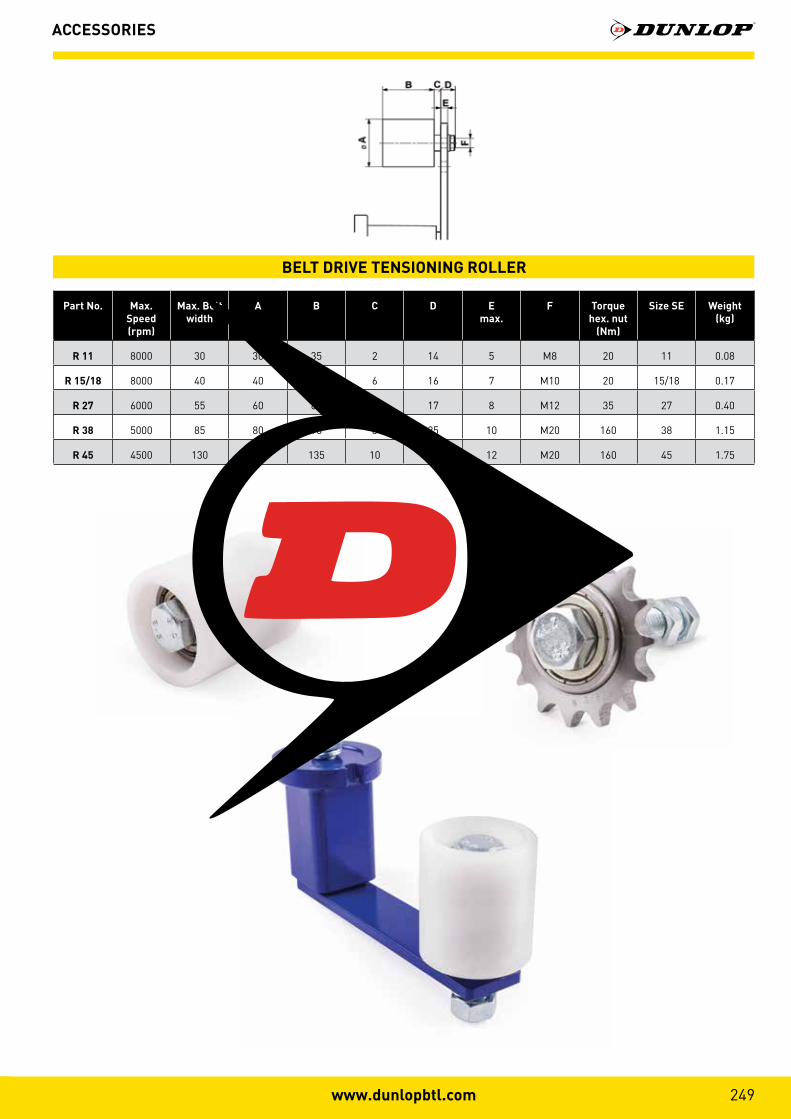
Part No. Max. Speed(rpm)
Max. Belt width
A B C D Emax.
F Torque hex. nut
(Nm)
Size SE Weight (kg)
R 11 8000 30 30 35 2 14 5 M8 20 11 0.08
R 15/18 8000 40 40 45 6 16 7 M10 20 15/18 0.17
R 27 6000 55 60 60 8 17 8 M12 35 27 0.40
R 38 5000 85 80 90 8 25 10 M20 160 38 1.15
R 45 4500 130 90 135 10 27 12 M20 160 45 1.75
BELT DRIVE TENSIONING ROLLER
MOTOR BASES
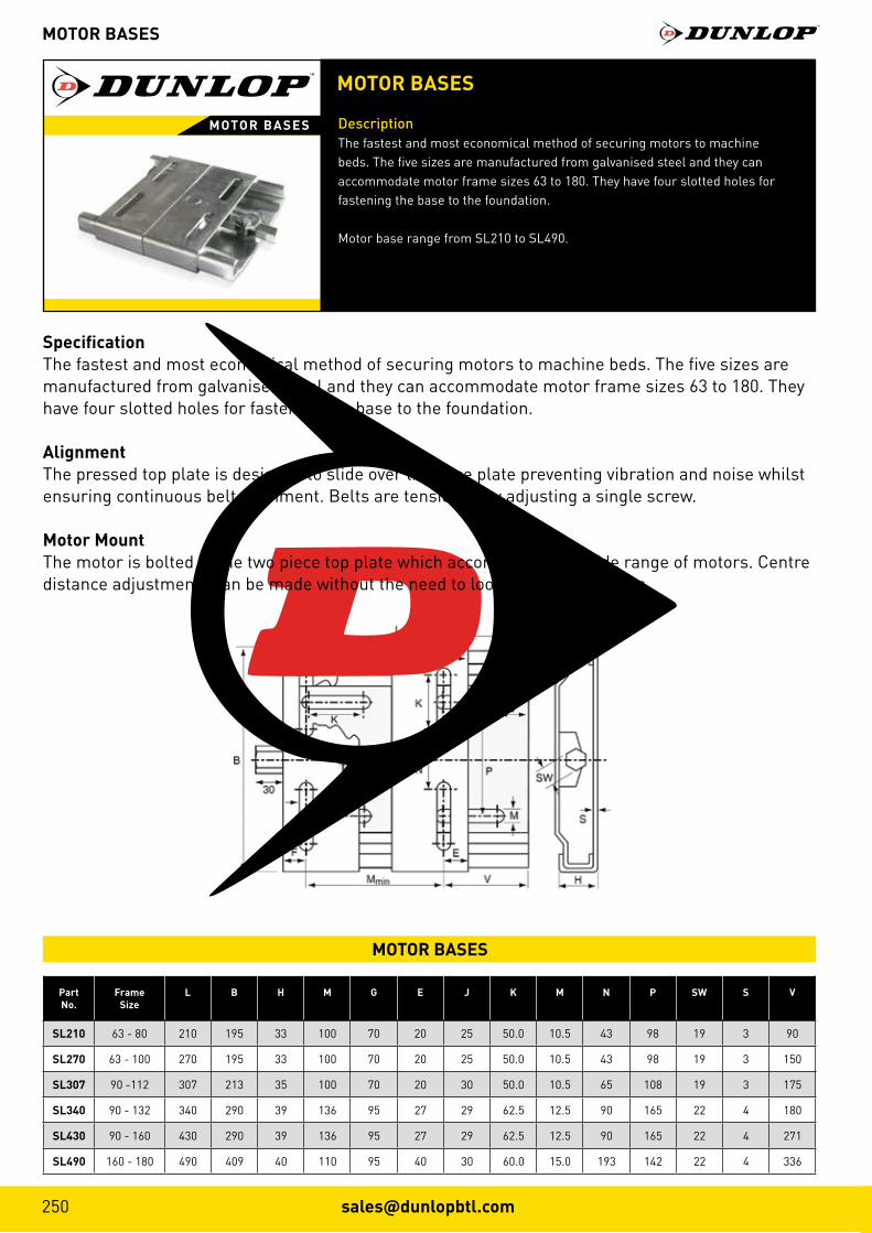
MOTOR BASES
DescriptionThe fastest and most economical method of securing motors to machinebeds. The five sizes are manufactured from galvanised steel and they can accommodate motor frame sizes 63 to 180. They have four slotted holes for fastening the base to the foundation.
Motor base range from SL210 to SL490.
MOTOR BASES
SpecificationThe fastest and most economical method of securing motors to machine beds. The five sizes are manufactured from galvanised steel and they can accommodate motor frame sizes 63 to 180. They have four slotted holes for fastening the base to the foundation.
AlignmentThe pressed top plate is designed to slide over the base plate preventing vibration and noise whilst ensuring continuous belt alignment. Belts are tensioned by adjusting a single screw.
Motor MountThe motor is bolted to the two piece top plate which accommodates a wide range of motors. Centre distance adjustments can be made without the need to loosen the motor bolts.
PartNo.
FrameSize
L B H M G E J K M N P SW S V
SL210 63 - 80 210 195 33 100 70 20 25 50.0 10.5 43 98 19 3 90
SL270 63 - 100 270 195 33 100 70 20 25 50.0 10.5 43 98 19 3 150
SL307 90 -112 307 213 35 100 70 20 30 50.0 10.5 65 108 19 3 175
SL340 90 - 132 340 290 39 136 95 27 29 62.5 12.5 90 165 22 4 180
SL430 90 - 160 430 290 39 136 95 27 29 62.5 12.5 90 165 22 4 271
SL490 160 - 180 490 409 40 110 95 40 30 60.0 15.0 193 142 22 4 336
MOTOR BASES
251www.dunlopbtl.com
SHAFT COLLAR - METRIC
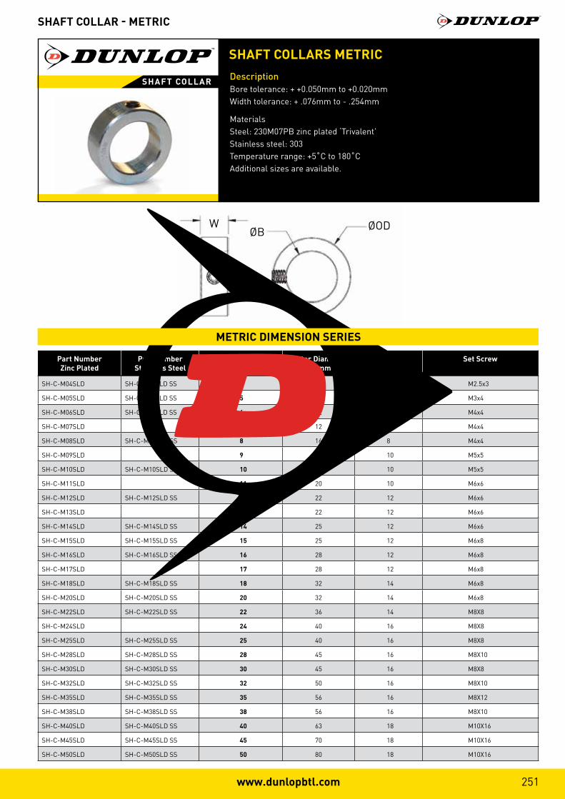
SHAFT COLLARS METRICDescriptionBore tolerance: + +0.050mm to +0.020mm Width tolerance: + .076mm to - .254mm
Materials Steel: 230M07PB zinc plated ‘Trivalent’ Stainless steel: 303 Temperature range: +5˚C to 180˚C Additional sizes are available.
SHAFT COLLAR
Part NumberZinc Plated
Part NumberStainless Steel
BoreB (mm)
Outer DiametreOD (mm)
WidthW (mm)
Set Screw
SH-C-M04SLD SH-C-M045LD SS 4 8 5 M2.5x3
SH-C-M05SLD SH-C-M045LD SS 5 10 6 M3x4
SH-C-M06SLD SH-C-M065LD SS 6 12 8 M4x4
SH-C-M07SLD 7 12 8 M4x4
SH-C-M08SLD SH-C-M08SLD SS 8 16 8 M4x4
SH-C-M09SLD 9 18 10 M5x5
SH-C-M10SLD SH-C-M10SLD SS 10 20 10 M5x5
SH-C-M11SLD 11 20 10 M6x6
SH-C-M12SLD SH-C-M12SLD SS 12 22 12 M6x6
SH-C-M13SLD 13 22 12 M6x6
SH-C-M14SLD SH-C-M14SLD SS 14 25 12 M6x6
SH-C-M15SLD SH-C-M15SLD SS 15 25 12 M6x8
SH-C-M16SLD SH-C-M16SLD SS 16 28 12 M6x8
SH-C-M17SLD 17 28 12 M6x8
SH-C-M18SLD SH-C-M18SLD SS 18 32 14 M6x8
SH-C-M20SLD SH-C-M20SLD SS 20 32 14 M6x8
SH-C-M22SLD SH-C-M22SLD SS 22 36 14 M8X8
SH-C-M24SLD 24 40 16 M8X8
SH-C-M25SLD SH-C-M25SLD SS 25 40 16 M8X8
SH-C-M28SLD SH-C-M28SLD SS 28 45 16 M8X10
SH-C-M30SLD SH-C-M30SLD SS 30 45 16 M8X8
SH-C-M32SLD SH-C-M32SLD SS 32 50 16 M8X10
SH-C-M35SLD SH-C-M35SLD SS 35 56 16 M8X12
SH-C-M38SLD SH-C-M38SLD SS 38 56 16 M8X10
SH-C-M40SLD SH-C-M40SLD SS 40 63 18 M10X16
SH-C-M45SLD SH-C-M45SLD SS 45 70 18 M10X16
SH-C-M50SLD SH-C-M50SLD SS 50 80 18 M10X16
WØB ØOD
METRIC DIMENSION SERIES

Part NumberZinc Plated
Part NumberStainless Steel
BoreB (mm)
Outer DiametreOD (mm)
WidthW (mm)
Set Screw
SH-C-03 SH-3-SS 0.1875 7/16 0.280 #8-32x1/8
SH-C-04 SH-4-SS 0.2500 1/2 0.281 #8-32x1/8
SH-C-05 SH-5-SS 0.3125 5/8 0.344 #10-32x5/32
SH-C-06 SH-6-SS 0.3750 3/4 0.375 1/4-20x3/16
SH-C-07 0.4375 7/8 0.438 1/4-20X1/4
SH-C-08 SH-8-SS 0.5000 1 0.438 1/4-20x1/4
SH-C-09 0.5625 1 0.438 1/4-20X1/4
SH-C-10 SH-10-SS 0.6250 1-1/8 0.500 5/16-18x1/4
SH-C-11 0.6875 1-1/4 0.563 5/16-18X1/4
SH-C-12 SH-12-SS 0.7500 1-1/4 0.563 5/16-18x1/4
SH-C-13 0.8125 1-5/16 0.563 5/16-18X1/4
SH-C-14 SH-14-SS 0.8750 1-1/2 0.563 5/16-18x5/16
SH-C-15 0.9375 1-5/8 0.563 5/16-18x5/16
SH-C-16 SH-16-SS 1.0000 1-5/8 0.625 5/16-18x5/16
SH-C-17 1.0625 1-3/4 0.625 5/16-18x5/16
SH-C-18 SH-18-SS 1.1250 1-3/4 0.625 5/16-18x5/16
SH-C-19 SH-19-SS 1.1875 2 0.688 3/8-16x3/8
SH-C-20 SH-20-SS 1.2500 2 0.688 3/8-16x3/8
SH-C-21 SH-21-SS 1.3125 2-1/8 0.688 3/8-16x3/8
SH-C-22 SH-22-SS 1.3750 2-1/8 0.750 3/8-16x3/8
SH-C-23 1.4375 2-1/4 0.750 3/8-16X3/8
SH-C-24 SH-24-SS 1.5000 2-1/4 0.750 3/8-16x3/8
SH-C-26 SH-26-SS 1.6250 2-1/2 0.813 3/8-16x3/8
SH-C-28 SH-28-SS 1.7500 2-3/4 0.875 1/2-13x1/2
SH-C-31 1.9375 3 0.875 1/2-13x1/2
SH-C-32 SH-32-SS 2.0000 3 0.875 1/2-13x1/2
WØB ØOD
SHAFT COLLAR - IMPERIAL
SHAFT COLLARS IMPERIALDescriptionBore tolerance: Up to 1” + .0005” to + .002” 1-1/16” to 2” + .0005” to + .003” Materials Steel: 230M07PB zinc plated “Trivalent” Stainless Steel: 303 Temperature range: +5˚C to + 180˚C Additional sizes are available.
SHAFT COLLAR
IMPERIAL DIMENSION SERIES

“We are proud to be a European manufacturer; it is a privilege
to supply our products to some of the world’s most prestigious
original equipment manufacturers in the Agricultural, Automotive,
Construction, Industrial and Motor Sport sectors”.
“Our distributor network is vital to the continued global growth
of the DUNLOP brand and our valued distributor partners form the
perfect link between manufacturer and end user”.
“Our commitment to our staff, our customers and the environment
is of paramount importance to our company, we will continue to
develop our organisational skills to further enhance our company’s
potential, to engage in sustainable practices and anticipate the
needs and expectations of our customers”.
“We love our products”.
Ray Mifsud, Managing Director.
Agriculture
Automotive
Construction
Industrial
Motor Sport#WeLoveOurProducts
www.dunlopbtl.com

T R A N S M I SS I O N S
DUNLOP™ and the Flying D device™ are used under licence by DUNLOP BTL Ltd.
DUNLOP BTL Ltd, MPT House, Brunswick Road, Cobbs Wood Industrial Estate, Ashford, Kent TN23 1EL, UK
T: +44 (0)1233 663340 = F: +44 (0)1233 664440 = E: [email protected] = W: www.dunlopbtl.com