Embed Size (px)
Citation preview
Mechanical Properties of Flux Cored Iron-Manganese-Aluminum Weld Metal
Substitute consumables for welding stainless steel are compared to standard austenitic electrodes
BY K. MAKHAMREH A N D D. AIDUN
ABSTRACT. For the first time, the room-temperature mechanical properties of six flux cored Fe-Mn-AI consumables were evaluated. Tension tests, microhardness measurements and ferrite content measurements were conducted on all six weld metals. The ductility of the weld metal with the highest tensile and yield strengths was greatly reduced due to solidification cracking because of high contents of Mn, Si and P. The other five weld metals possessed adequate strength and ductility. The characteristic solidification morphologies exhibited by these weld metals were determined. The variations in the multipass weld metal solidification morphologies and ferrite contents were due to the combined effects of the alloying elements. The Fe-Mn-Al consumables possessed better room-temperature mechanical properties than similar conventional 310 and 316 stainless steel consumables.
Introduction
Iron-manganese-aluminum (Fe-Mn-Al) alloys have been investigated extensively to assess their capability as partial replacements of conventional stainless steels, in particular the austenitic type of stainless steel. Numerous papers have been published on the mechanical properties, oxidation and corrosion behavior, solidification morphologies, effect of alloying elements, and weldability characteristics of Fe-Mn-Al alloys (Refs. 1-20). However, until now no effort has been made to investigate the mechanical properties of Fe-Mn-AI-X (flux cored) weld metals.
The mechanical properties of Fe-Mn-Al alloys at temperatures ranging from -196oC(-320°F)to815°C(1500c 'F)were
K. MAKHAMREH is a WRC/EWI Fellow and D. AIDUN is an Associate Professor in the Department of Mechanical and Aeronautical Engineering, Clarkson University, Potsdam, N. Y.
Paper presented at the 72nd Annual AWS Meeting held April 14-19, 1991, in Detroit. Mich.
investigated by a number of researchers (Refs. 1-8). Fe-Mn-Al weldments possessed room-temperature mechanical properties comparable to 310 and 316 stainless steels (Ref. 1). Autogenous gas tungsten arc (GTA) weld samples exhibited high-tensile strength in both the longitudinal and the transverse direction. However, the ductility of the butt-jointed samples was less than that of the base metals. Fe-Mn-Al alloys with carbon and silicon additions were studied at — 196°C and at room temperature by Charles, etal. (Ref. 2). These alloys possessed a higher strength at —196 = C and at room temperature due to the solution hardening caused by the carbon and silicon additions. The solution hardening was more effective at — 196°C The ductility decreased slowly with silicon additions. With carbon additions, however, the ductility deteriorated quickly, especially at —196°C Three Fe-Mn-Al-C-X alloys processed by a controlled hot rolling process (Ref. 3) and examined at temperatures ranging from room temperature to -196°C possessed the highest strength and ductility at -196°C.
An Fe-Mn-Al alloy with four different compositions was tested for strength, hardness and ductility properties (Ref. 4). The study revealed that the four alloys possessed better strength and hardness than a typical brass alloy used in the propellers of seagoing vessels. The ductilities of the four alloys were comparable to that
KEY WORDS
FCAW Fe-Mn-Al Fe-Cr-Ni Room Temperature Mechanical Properties Tensile Strength Yield Strength Microhardness Ferrite Content Ductility
of the brass alloy. Wang and Beck suggested that the Fe-Mn-Al-Si alloy system is a strong candidate to replace brass for seagoing ship propellers. In another study, the mechanical properties and fatigue behavior of three solution-treated Fe-Mn-Al-C alloys, both austenitic and duplex, were examined (Ref. 5). The austenitic alloy exhibited the highest strength and ductility. The fatigue behaviors of the three alloys were compatible with no significant differences.
A work hardening study on three Fe-Mn-Al-C alloys suggested "deformation twinning" as a major cause of work hardening in these alloys (Ref. 6). Serrated stress-strain curves were observed in which the serration was a function of aluminum content. As the aluminum content decreased, the serration of the stress-strain curve increased. Work hardening measurements based on the difference in flow stress (Au) values at plastic strains of 0.002 and 0.04 showed that work hardening increased as aluminum content decreased. The work done by Kim, ef al. (Ref. 3), supported the hypothesis of work hardening by deformation twinning. The hardening of the alloy was attributed to "strain-induced mechanical twinning," and the increase in strength and ductility as temperature decreased was attributed to the increased number of twins formed at low temperatures. In addition, the high number of twins formed at low temperatures prevented local deformation, which resulted in a multiple necking along the gauge section and yielded the high uniform elongation observed at low temperatures. In both studies (Refs. 3, 6), no evidence of martensitic transformations was observed. Another work by Kim, ef al. (Ref. 7), concluded that there should be a balance between work hardening rate and strain in order to achieve high-tensile ductility. Deformation twins enhanced the tensile ductility but were not the major controlling parameter. It was also found that the amount of deformation twins formed in 30 wt-% Mn and variable Al and C iron alloys increased with decreasing
104-s I M A R C H 1992
carbon and aluminum content. A number of Fe-Mn-AI-C (with and
without the addition of silicon) alloys were tested at temperatures ranging from room temperature to 815°C (Ref. 8). One particular alloy containing 30 Mn, 8 Al, 1 C, 1.5 Si and balance Fe exhibited a strength higher than that of commercial stainless steels at room temperature. For this alloy, a tensile strength of approximately 100 ksi with 5% elongation was attained at 650°C (1200°F).
The oxidation and corrosion behavior of Fe-Mn-Al alloys was examined by numerous researchers (Refs. 4, 8-12). The Fe-Mn-Al alloys exhibited better corrosion fatigue resistance and cavitation erosion than conventional stainless steels. However, the alloys were more susceptible to pitting and general corrosion in chloride-containing environments. The oxidation resistance was inferior compared to austenitic stainless steels and binary iron-aluminum alloys. The stress-corrosion cracking susceptibility of the Fe-Mn-Al alloys in comparison with conventional stainless steels has not yet been fully evaluated.
Microstructural characteristics and solidification processes of Fe-Mn-Al alloys also were studied. The microstructure of 24.6 Mn, 6.6 Al, 1 C, 3.1 Mo and balance Fe alloy consisted of austenite and ferrite phases without precipitates in the as-quenched condition. When the alloy was aged at temperatures ranging from 450°C (840°F) to 800°C (1470°F), complex precipitates were observed in both the austenite and ferrite phases (Ref. 13).The solidification morphologies of two Fe-Mn-Al alloys subjected to GTA spot welds showed acicular and vermicular morphologies, depending on the carbon content (Ref. 14). Six Fe-Mn-Al alloys with different carbon and silicon contents subjected to autogenous GTA-welding showed six different morphologies; fully austenitic, skeletal ferrite, vermicular austenite, lacy ferrite, acicular austenite and Widmanstatten austenite (Ref. 15).
A large number of studies on Fe-Mn-Al alloys examined the effect of one element (or more) on the behavior of the alloy system. It is well known that carbon is an austenitic stabilizer (Refs. 2, 4, 8, 16) that contributes to the alloy's strength and hardening (Refs. 2, 4, 5). At low temperatures, carbon additions played a more important role in the alloy's strengthening (Refs. 2, 5, 7). Also, fagitue-crack propagation was a function of carbon content in the alloy (Ref. 5). Carbon content had a strong influence on the amount of residual ferrite in the Fe-Mn-Al welds, which in turn affected the characteristic morphologies of these welds (Refs. 1,14,17). Carbon also had a detrimental effect on the oxidation resistance of Fe-Mn-Al alloys (Refs. 8,18). Silicon was reported to be a ferritic stabilizer (Ref. 2) and had an important hardening effect at room temper
ature as well as at high temperatures (Refs. 2,8). Ductility was found to depend highly on Si content; as the Si content increased, the ductility decreased (Ref. 4). Silicon improved the oxidation resistance (Ref. 8) and decreased the weldability of the Fe-Mn-Al alloy system (Ref. 19).
Other elements also were investigated. Manganese was found to be an austenitic stabilizer (Refs. 4, 8,16). This element played a major role in strengthening the alloy and improved the alloy's high-temperature properties (Ref. 16). If the Mn content exceeded 30 wt-% in the alloy, a brittle phase <3-Mn formed and adversely affected the mechanical properties (Ref. 8). Oxidation properties also were adversely affected by the Mn content (Ref. 8). Aluminum improved the oxidation and corrosion resistance of the alloy (Refs. 2, 4, 8) but decreased the work hardening (Ref. 6). Nitrogen increased the stability of the austenitic phase and had an important hardening effect (Ref. 2). Additions of N, however, could produce inclusions in the alloy such as aluminum nitrides (Ref. 8). Boron drastically reduced the oxidation resistance (Ref. 8). Nickel was determined to be expensive and disrupted the formation of a continuous alumina film (Ref. 12). Room-temperature strength was enhanced with Ni additions but ductility was drastically reduced (Ref. 8). Niobium and vanadium additions to the Fe-Mn-Al-C alloy resulted in higher strength when more Nb than V was added (Ref. 3). Optimal properties were achieved when the Al content was between 8 and 10 wt-% and the Mn content was between 25 and 30 wt-% (Ref. 20).
Further studies of Fe-Mn-Al alloys revealed good welding characteristics. No crack was seen in a number of U-bend test samples and butt joints when the GTA-autogenous welding technique was used (Ref. 1). In the work done by Chou and Lee (Ref. 17), it was observed that Widmanstatten austenite and acicular austenite morphology types exhibited a greater
hot-crack susceptibility than the vermicular ferrite or lacy ferrite morphology types.
The objective of this study was to examine for the first time the room-temperature mechanical properties of flux cored Fe-Mn-Al consumables. These weld metals were deposited using the flux cored arc welding (FCAW) technique to obtain a workable weld metal thickness. The characteristic solidification morphologies, the ferrite contents and the effects of different alloying elements on the mechanical properties of the weld metals were investigated. The six Fe-Mn-Al weld metals are compared with conventional 310 and 316 stainless steel weld metals prepared in a similar fashion.
Materials and Experimental Procedures
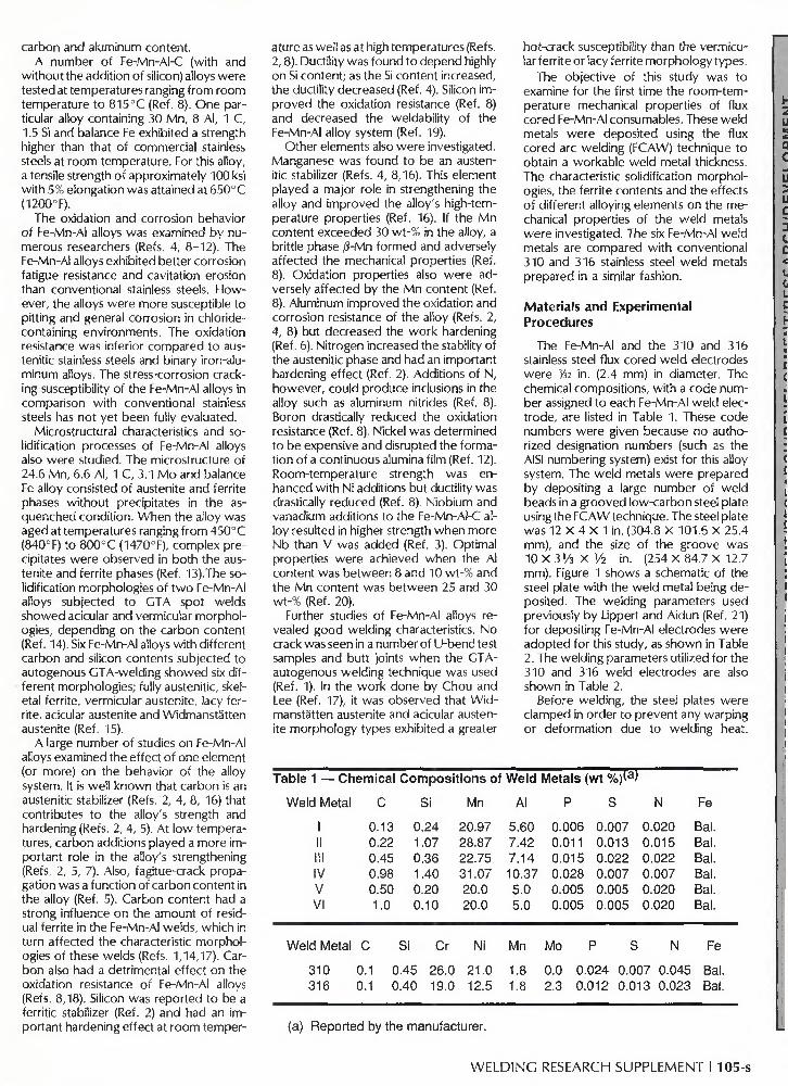
The Fe-Mn-Al and the 310 and 316 stainless steel flux cored weld electrodes were ¥n in. (2.4 mm) in diameter. The chemical compositions, with a code number assigned to each Fe-Mn-Al weld electrode, are listed in Table 1. These code numbers were given because no authorized designation numbers (such as the AISI numbering system) exist for this alloy system. The weld metals were prepared by depositing a large number of weld beads in a grooved low-carbon steel plate using the FCAW technique. The steel plate was 12 X 4 X 1 in. (304.8 X 101.6 X 25.4 mm), and the size of the groove was 10 X 3 !/3 X i/2 in. (254 X 84.7 X 12.7 mm). Figure 1 shows a schematic of the steel plate with the weld metal being deposited. The welding parameters used previously by Lippert and Aidun (Ref. 21) for depositing Fe-Mn-Al electrodes were adopted for this study, as shown in Table 2. The welding parameters utilized for the 310 and 316 weld electrodes are also shown in Table 2.
Before welding, the steel plates were clamped in order to prevent any warping or deformation due to welding heat.
Table 1 — Chemical Compositions of Weld Metals (wt %)(a)
Weld Metal C Si Mn Al P S N
I II III IV V VI
0.13 0.22 0.45 0.98 0.50 1.0
0.24 1.07 0.36 1.40 0.20 0.10
20.97 28.87 22.75 31.07 20.0 20.0
5.60 7.42 7.14 10.37 5.0 5.0
0.006 0.011 0.015 0.028 0.005 0.005
0.007 0.013 0.022 0.007 0.005 0.005
0.020 0.015 0.022 0.007 0.020 0.020
Fe
Bal. Bal. Bal. Bal. Bal. Bal.
Weld Metal C
310 0.1 316 0.1
Si
0.45 0.40
Cr
26.0 19.0
Ni
21.0 12.5
Mn
1.8 1.8
Mo
0.0 2.3
P S N
0.024 0.007 0.045 0.012 0.013 0.023
Fe
Bal. Bal.
(a) Reported by the manufacturer.
W E L D I N G RESEARCH SUPPLEMENT I 105-s
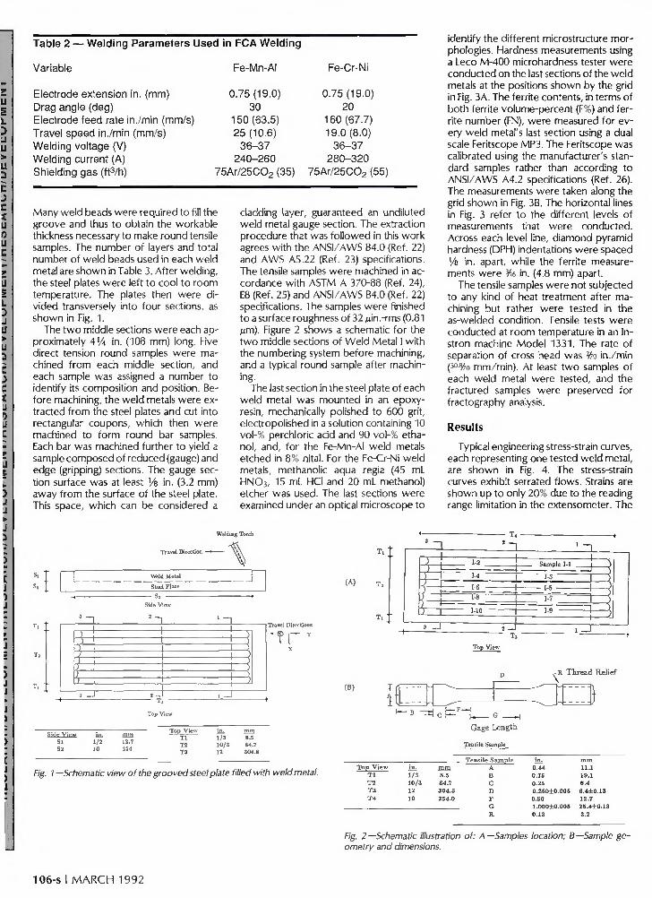
Table 2 — Welding Parameters Used in FCA Welding
Variable Fe-Mn-Al Fe-Cr-Ni
Electrode extension in. (mm) Drag angle (deg) Electrode feed rate in./min (mm/s) Travel speed in./min (mm/s) Welding voltage (V) Welding current (A) Shielding gas (ft3/h)
0.75(19.0) 30
150(63.5) 25(10.6)
36-37 240-260
0.75(19.0) 20
160(67.7) 19.0(8.0)
36-37 280-320
75Ar/25C02 (35) 75Ar/25C02 (55)
Many weld beads were required to fill the groove and thus to obtain the workable thickness necessary to make round tensile samples. The number of layers and total number of weld beads used in each weld metal are shown in Table 3. After welding, the steel plates were left to cool to room temperature. The plates then were divided transversely into four sections, as shown in Fig. 1.
The two middle sections were each approximately AVA in. (108 mm) long. Five direct tension round samples were machined from each middle section, and each sample was assigned a number to identify its composition and position. Before machining, the weld metals were extracted from the steel plates and cut into rectangular coupons, which then were machined to form round bar samples. Each bar was machined further to yield a sample composed of reduced (gauge) and edge (gripping) sections. The gauge section surface was at least V& in. (3.2 mm) away from the surface of the steel plate. This space, which can be considered a
cladding layer, guaranteed an undiluted weld metal gauge section. The extraction procedure that was followed in this work agrees with the ANSI/AWS B4.0 (Ref. 22) and AWS A5.22 (Ref. 23) specifications. The tensile samples were machined in accordance with ASTM A 370-88 (Ref. 24), E8 (Ref. 25) and ANSI/AWS B4.0 (Ref. 22) specifications. The samples were finished to a surface roughness of 32 juin.-rms (0.81 Mm). Figure 2 shows a schematic for the two middle sections of Weld Metal I with the numbering system before machining, and a typical round sample after machining.
The last section in the steel plate of each weld metal was mounted in an epoxy-resin, mechanically polished to 600 grit, electropolished in a solution containing 10 vol-% perchloric acid and 90 vol-% ethanol, and, for the Fe-Mn-Al weld metals etched in 8% nital. For the Fe-Cr-Ni weld metals, methanolic aqua regia (45 mL HNO3, 15 mL HCI and 20 mL methanol) etcher was used. The last sections were examined under an optical microscope to
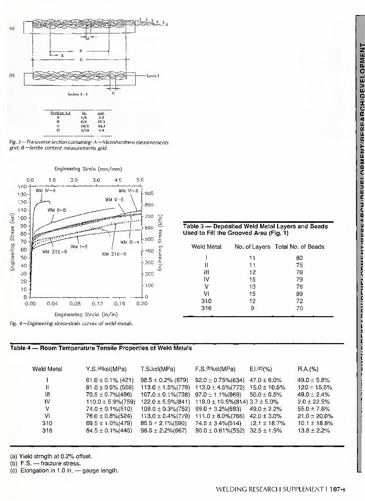
identify the different microstructure morphologies. Hardness measurements using a Leco M-400 microhardness tester were conducted on the last sections of the weld metals at the positions shown by the grid in Fig. 3A. The ferrite contents, in terms of both ferrite volume-percent (F%) and ferrite number (FN), were measured for every weld metal's last section using a dual scale Feritscope MP3. The Feritscope was calibrated using the manufacturer's standard samples rather than according to ANSI/AWS A4.2 specifications (Ref. 26). The measurements were taken along the grid shown in Fig. 3B. The horizontal lines in Fig. 3 refer to the different levels of measurements that were conducted. Across each level line, diamond pyramid hardness (DPH) indentations were spaced Vs in. apart, while the ferrite measurements were 3/i6 in. (4.8 mm) apart.
The tensile samples were not subjected to any kind of heat treatment after machining but rather were tested in the as-welded condition. Tensile tests were conducted at room temperature in an Instron machine Model 1331. The rate of separation of cross head was Vm in./min (50%3 mm/min). At least two samples of each weld metal were tested, and the fractured samples were preserved for fractography analysis.
Results
Typical engineering stress-strain curves, each representing one tested weld metal, are shown in Fig. 4. The stress-strain curves exhibit serrated flows. Strains are shown up to only 20% due to the reading range limitation in the extensometer. The
Travel Direction
r 3 n
Weld Metal
Steel Plate
Side View
! - 1 ' "I
> ' ' \ \ ) ] i i >
) i i i ) ' i i } > > > >
J i i i 3 - J 2 - J 1 - 1
^
(A)
Travel Directions
(B)
12.7 254
Top View UK m m T l 1/3 8.5 T2 10/3 84.7 T 3 12 304.8
T j
T A- 1"
-=i
Top View
R Thread Relief
Gage Length
Tensile Sample
Fig. 1 —Schematic view of the grooved steel plate filled with weld metal. T o p View
T l T 2 T 3 T 4
in. 1/3 1 0 / 3 12 10
rn in 8.5 84.7 304.8 254.0
e S a m p l e A B C D F G R
0.44 0.75 0.25 0.250±0.O05 0.50 1.000±0.005 0.13
m m 11.1 18.1 6.4 6 .4±0 .13 12.7 25 .4±0 .13 3.2
Fig. 2—Schematic illustration of: A—Samples location; B—Sample geometry and dimensions.
106-s I M A R C H 1992
w
(b)
Section 3-3 A B C
D
iiL 1/8 9 / 4 10/3 3/1G
m m 3.2 57.2 84.7 4.8
Fig. 3 — Transverse section containing: A —Microhardness measurements grid; B—ferrite content measurements grid.
Engineering Strain (mm/mm)
0.0 1.0 2.0 3.0 4.0 5.0 140
130 -
120 -
1 1 0 -
1 0 0 -
9 0 -
8 0 -
7 0 -
6 0 -
5 0 -
40 -
3 0 -
2 0 -
1 0 -
WM iV-4
/ WM
ifrr^SS^-
WM 31
it—5
, « - * "
WM I-5
WM VI —6
WM V - 5 \
.•.v-W"***"]
j WM III-4
WM 316 -6
2 0.16 0.
-900
-800
-700
-600
-500
r400
-300
-200
- 100
20
Fig.
0.00 0.04 0.08 0.12
Engineering Strain ( in / in )
4 —Engineering stress-strain curves of weld metals.
Table 3 — Deposited Weld Metal Layers and Beads Used to Fill the Grooved Area (Fig. 1)
Weld Metal No. of Layers Total No. of Beads
II III IV V VI
310 316
11 11 12 15 13 15 12 9
80 75 78 79 76 89 72 70
Table 4 — Room Temperature Tensile Properties of Weld Metals
Weld Metal
I II III IV V VI
310 316
Y.S.<a)ksi(MPa) T.S.ksi(MPa)
61.0 ± 0 . 1 % (421) 81.0 + 0.5% (559) 70.5 ± 0.7%(486) 110.0±5.9%(759) 74.0 +0.1 %(510) 76.0 ± 0.8%(524) 69.5 ± 1.0%(479) 64.5 ± 0.1 %(445)
98.5 ± 0.2% (679) 113.0+ 1.5%(779) 107.0 +0.1 %(738) 122.0±5.5%(841) 109.0 ±0.3%(752) 113.0 + 0.4%(779) 85.5 +2.1 %(590) 96.5 ± 2.2%(667)
F.S.(b)ksi(MPa) El.(c)(%) R.A.(%)
92.0 + 0.75%(634) 47.0 + 6.0% 49.0 + 5.8% 112.0±4.5%(772) 15.0 ±10.5% 12.0 ±15.5% 97.0 ± 1.1%(669) 50.0 ± 0.5% 49.0 ± 2.4% 118.0 ± 10.5%(814) 3.7 ± 5.0% 2.0 ± 22.5% 99.0 ± 3.2%(683) 49.0 ± 2.2% 55.0 ± 7.6% 111.0±8.0%(766) 42.0 ±3.0% 21.0 ±20.0% 74.5±3.4%(514) 12.1 ± 18.7% 10.1 ± 18.8% 80.0 ± 0.61 %(552) 32.5 ± 1.5% 13.8 ± 2.2%
(a) Yield strngth at 0.2% offset. (b) F.S. — fracture stress. (c) Elongation in 1.0 in. — gauge length.
WELDING RESEARCH SUPPLEMENT I 107-s
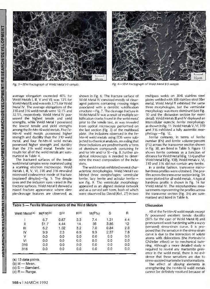
Fig. 5 —SEM fractograph of Weld Metal 1-5 sample. Fig. 6 —SEM fractograph of Weld Metal 11-5 sample.
average elongation exceeded 40% for Weld Metals I, III, V and VI; was 15% for Weld Metal II; and was only 3.7% for Weld Metal IV. The average elongations of the 310and 316 weld metals were 12.1% and 32.5%, respectively. Weld Metal IV possessed the highest tensile and yield strengths, while Weld Metal I possessed the lowest tensile and yield strengths among the Fe-Mn-Al weld metals. Five Fe-Mn-Al weld metals possessed higher strength and ductility than the 310 weld metal, and four Fe-Mn-Al weld metals possessed higher strength and ductility than the 316 weld metal. Tensile test results for all of the weld metals are summarized in Table 4.
The fractured surfaces of the tensile weld metal samples were examined using a scanning electron microscope. Weld Metals I, III, V, VI, 310 and 316 revealed microvoid coalescence mode of fracture (equiaxed dimples)—Fig. 5. The dimple sizes and the inclusion sizes varied in the fracture surfaces. Weld Metal II showed a mixed fracture appearance where dimple-cleavage features are observed, as
shown in Fig. 6. The fracture surface of Weld Metal IV consisted mostly of cleav-aged patterns containing crossing ridges associated with a dentritic solidification structure —Fig. 7. The cleavage fracture in Weld Metal IV was a result of multiple solidification cracks found in the weld metal prior to the tensile test, as was revealed from optical microscopy performed on the last section (Fig. 3) of the multibead plate. The inclusions observed in the Fe-Mn-Al weld metals using EDS were subjected to chemical analyses, revealing that these inclusions are predominantly a form of aluminum compounds containing Fe and/or Mn and/or Si—Fig. 8. Further analytical microscopy is needed to determine the exact composition of the inclusions.
The weld metals exhibited several characteristic morphologies. Weld Metal I exhibited three morphologies: vermicular ferrite, lacy ferrite and acicular ferrite — see Fig. 9. The vermicular morphology appeared as an aligned skeletal network and as a curved soft form, both of which were observed by David (Ref. 27) in two
Table 5 — Ferrite Measurements of the Weld Metals
Weld Metal<a> M(FN)C) S<c)
I II III IV V VI
310 316
6.7 51.7 6.2 9.9 0.0 0.0 0.0 0.0
0.87 4.44 1.02 2.3 0.0 0.0 0.0 0.0
RW
3.3 14 3.2 6.9 0.0 0.0 0.0 0.0
M(F%)
7.4 36 7.0 9.9 0.0 0.0 0.0 0.0
1.31 3.85 0.84 2.37 0.0 0.0 0.0 0.0
R
4.4 12 2.8 7.8 0.0 0.0 0.0 0.0
(a) 13 data points. (b) M — Mean. (c) S — Standard. (d) R — Range.
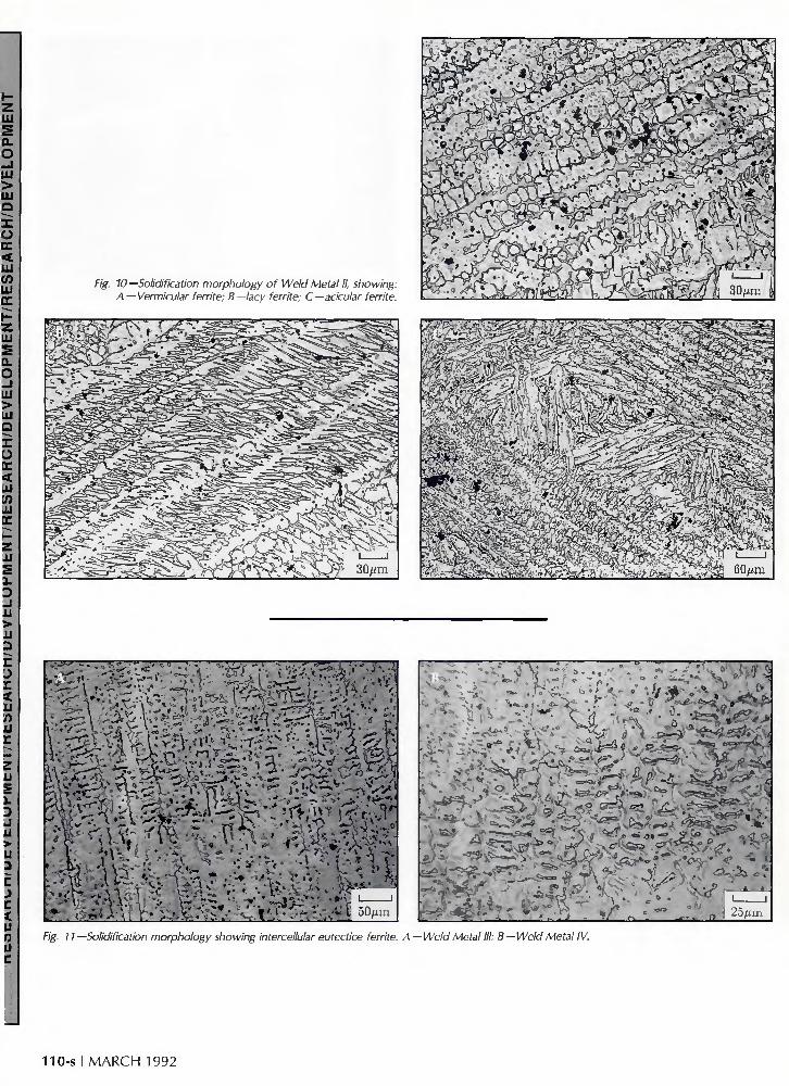
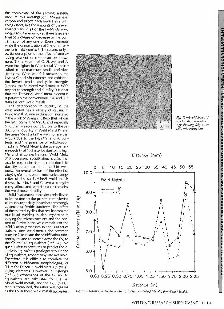
multipass welds on 304L stainless steel plates welded with 308 stainless steel filler metal. Weld Metal II exhibited the same three morphologies, but the vermicular morphology was more dominant (see Fig. 10 and the discussion section for more detail). Weld Metals III and IV displayed an intercellular eutectic ferrite morphology as shown in Fig. 11. Weld Metals V, VI, 310 and 316 exhibited a fully austenitic morphology—Fig. 12.
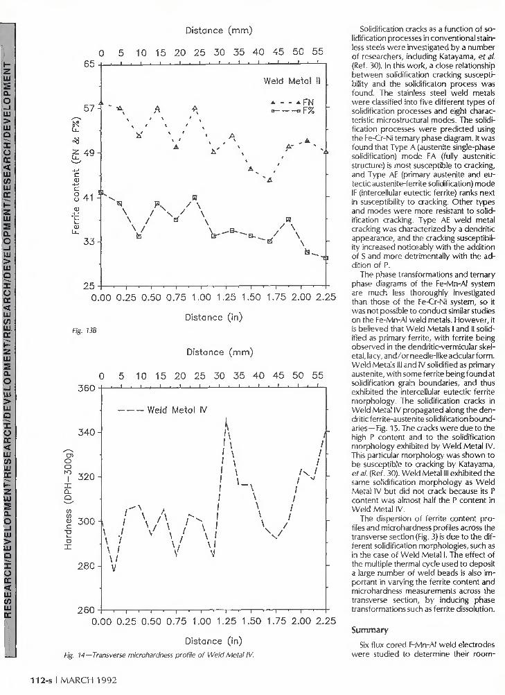
Ferrite contents, in terms of ferrite number (FN) and ferrite volume-percent (F%>) across the transverse section shown in Fig. 3B, are listed in Table 5. Figure 13 shows ferrite contents as a function of distance for Weld Metal I (Fig. 13A) and for Weld Metal ll (Fig. 13B). Weld Metals V, VI, 310 and 316 did not contain any ferrite.
In a similar fashion, transverse microhardness profiles were obtained. The profiles across the transverse section in Fig. 3A were plotted for all weld metals. A typical hardness profile is shown in Fig. 14 for Weld Metal IV. The microhardness measurements representing the profiles across the transverse section (Fig. 3A) are summarized and listed in Table 6.
Discussion
All of the Fe-Mn-Al weld metals except IV possessed excellent tensile ductility (50% for the case of Weld Metal III) and pronounced work hardening with a wavy (serrated) stress-strain curve. It is proposed that the serration in the stress-strain curve is due to the interaction of solute atoms with dislocations (the Portevin-Le Chatelier effect) or to mechanical twinning. Although a more detailed study is required to reveal any martensite presence in the weld metal, there is no evidence that these serrations are due to stress-assisted martensite transformations.
The effect of alloying elements in strengthening the Fe-Mn-Al weld metals cannot be definitely resolved because of
108-s I M A R C H 1992
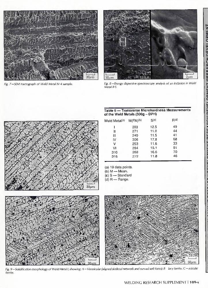
Fig. 7 —SEM fractograph of Weld Metal IV-4 sample. Fig. 8 —Energy dispersive spectroscopy analysis of an inclusion in Weld Metal 11-5.
V Jo*-! J^yn r * . JT\', ••« , <A .••<?•. £-£* *v> -~_/_. _ / ^ v - , •
Table 6 — Transverse Microhardness Measurements of the Weld Metals (300g - DPH)
S<c> R<d> Weld Metal<a> M(FN)W
1 II III IV V VI
310 316
(a) 19 data points (b)M — ( c ) S -( d ) R -
Mean. Standarc Range.
203 271 240 306 253 284 268 272
12.5 11.0 11.5 17.8 11.6 15.1 16.6 11.8
49 44 41 68 33 51 70 46
• ' T"*< J --_-r..3_«_ < _ n „ r . - , __m*W-—• " i * V"J—l -Ti _—i T l - .~r~T. . 1 i II - i _ • - r r_ _• . . . • — , i , . . . .
Fig. 9 —Solidification morphology of Weld Metal I, showing; A — Vermicular (aligned skelletal network and curved soft form); B —lacy ferrite; C —acicular ferrite ferrite
WELDING RESEARCH SUPPLEMENT I 109-s
rkt^'lA
•A) ih-••-'•«„>„ ;:;•;••; ;• W f i 1 , |
J* . i-^U-'V: ! - ' ; . . V ^ V ^ . ' . ' ^ - - > i 3Q;J::I
• • - — - s . : — o -«o p =
- ° • % • •*•"' r "A . •* 0 . . \ ^ \ t l f< % " A *
"~*•??-*>*> JfJ " •". "•$&?*& '"•-"'"•'•• • _/..'-; <=•*, <±'JSf'' 'a-- •''"'" ' - '
- . = ^ - i : * ^ > • d ^ ;
, -~i/' ' \ • * e " *
> »
ft ' i J 25/im
F/g. / / —Solidification morphology showing intercellular eutectice ferrite. A — Weld Metal III; B — Weld Metal IV.
110-s I MARCH 1992
the complexity of the alloying systems used in this investigation. Manganese, carbon and silicon each have a strengthening effect, but the amounts of these elements vary in all of the Fe-Mn-Al weld metals simultaneously; i.e., there is no systematic increase or decrease in the concentration of any one of these elements while the concentration of the other elements is held constant. Therefore, only a partial description of the effect of one alloying element or more can be drawn here. The contents of C, Si, Mn and Al were the highest in Weld Metal IV and resulted in the maximum tensile and yield strengths. Weld Metal I possessed the lowest C and Mn contents and exhibited the lowest tensile and yield strengths (among the Fe-Mn-Al weld metals). With respect to strength and ductility, it is clear that the Fe-Mn-Al weld metal system is superior to the conventional 310 and 316 stainless steel weld metals.
The deterioration of ductility in the weld metals has a variety of causes. In Weld Metal IV, one explanation indicated in the work of Wang and Beck (Ref. 4) was the high content of Mn, C and especially Si. Other possible contributors to the reduction in ductility in Weld Metal IV are: the presence of a brittle j3-Mn phase that occurs due to the high Mn and Al contents; and the presence of solidification cracks. In Weld Metal II, the average tensile ductility of 15% may be due to the high Mn and Si concentrations. Weld Metal 310 possessed solidification cracks that may be responsible for the reduction in its ductility as compared to the 316 weld metal. An overall picture of the effect of alloying elements on the mechanical properties of the six Fe-Mn-Al weld metals shows that Mn, Si and C have a strengthening effect and contribute to reducing the weld metal ductility.
Solidification morphologies are believed to be related to the presence of alloying elements, especially those that are strongly austenitic or ferritic stabilizers. The effect of the thermal cycling that results from the multibead welding is also important in varying the microstructures and the content of ferrite in the weld metals. For the solidification processes in the 300-series stainless steel weld metals, the common practice is to relate the solidification morphologies, and to some extend the FN, to the Cr and Ni equivalents (Ref. 28). No quantitative expressions to predict the Al and Mn equivalents (analogous to Cr and Ni equivalents, respectively) are available. Therefore, it is difficult to correlate the different solidification morphologies, or FN, in the Fe-Mn-Al weld metals to the alloying elements. However, if Delong's (Ref. 29) expressions of the Cr and Ni equivalents are calculated for the Fe-Mn-Al weld metals, and the Creq to Nieq
ratio is computed, the ratios will increase as the FN in these weld metals increases.
I r.'-y ,-• • •-' •" ""; --60/jm
Fig. 12-Weld Metal V solidification morphology showing fully austenitic microstructure.
Distance (mm)
0 5 10 15 20 25 30 35 40 45 50 55 "J 0 Q .1 . I , I > I 1 1 1 1 1 1 1 1 1 1 1 1 1 1 1 L
L L
c a. *-* c o o
9.0
8.0
7 . 0 -
6.0
5.0
Weld Metal I
B BF% _v - - A FN
K
\ / / \
\ X ~ L I / ' \ I I / I / 1 /
8
* ^ h--*^ I V a
w i\ 1 \ 1 \ 1 I / A \ / . . \ / ' > \ / ' < . ( l \
/ ' A
Y* l'\ . ; ' .; /, /. / •
/• / ' / ;
A
\
"A- •y
Fig.
0.00 0.25 0.50 0.75 1.00 1.25 1.50 1.75 2.00 2.25
Distance (in) 13 — Transverse ferrite content profiles. A — Weld Metal I; B — Weld Metal II.
W E L D I N G RESEARCH SUPPLEMENT I 111-s
Distance (mm)
0 5 10 15 20 25 30 35 40 45 50 55 6 5 -i-—. i . i * i I - J — . — i — . — i — . — i — . — i — . — i — • — i — ' — i
57
6 ^
Z Lu
4 9 -
c a)
§41
cu L__
33
,4
Weld Metal I
* - - * FN • »F%
tf \ s
A'
EJ K B
\ / Ef
\ / ta
\ V- - B ~ .
B / \
Bf \
__. -a
2 5 -i ' 1 • 1 • 1 • i ' 1 ' 1 • 1 ' r
0.00 0.25 0.50 0.75 1.00 1.25 1.50 1.75 2.00 2.25
Fig. 13B
Distance (in)
Distance (mm)
0 5 10 15 20 25 30 35 40 45 50 55
~i • — i — ' — r
0.00 0.25 0.50 0.75 1.00 1.25 1.50 1.75 2.00 2.25
Distance (in)
Fig. 14 —Transverse microhardness profile of Weld Metal IV.
Solidification cracks as a function of solidification processes in conventional stainless steels were investigated by a number of researchers, including Katayama, ef al. (Ref. 30). In this work, a close relationship between solidification cracking susceptibility and the solidificaton process was found. The stainless steel weld metals were classified into five different types of solidification processes and eight characteristic microstructural modes. The solidification processes were predicted using the Fe-Cr-Ni ternary phase diagram. It was found that Type A (austenite single-phase solidification) mode FA (fully austenitic structure) is most susceptible to cracking, and Type AE (primary austenite and eutectic austenite-ferrite solidification) mode IF (intercellular eutectic ferrite) ranks next in susceptibility to cracking. Other types and modes were more resistant to solidification cracking. Type AE weld metal cracking was characterized by a dendritic appearance, and the cracking susceptibility increased noticeably with the addition of S and more detrimentally with the addition of P.
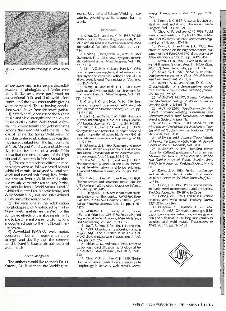
The phase transformations and ternary phase diagrams of the Fe-Mn-Al system are much less thoroughly investigated than those of the Fe-Cr-Ni system, so it was not possible to conduct similar studies on the Fe-Mn-Al weld metals. However, it is believed that Weld Metals I and II solidified as primary ferrite, with ferrite being observed in the dendritic-vermicular skeletal, lacy, and/or needle-like acicular form. Weld Metals III and IV solidified as primary austenite, with some ferrite being found at solidification grain boundaries, and thus exhibited the intercellular eutectic ferrite morphology. The solidification cracks in Weld Metal IV propagated along the dendritic ferrite-austenite solidification boundaries—Fig. 15. The cracks were due to the high P content and to the solidification morphology exhibited by Weld Metal IV. This particular morphology was shown to be susceptible to cracking by Katayama, etal. (Ref. 30). Weld Metal III exhibited the same solidification morphology as Weld Metal IV but did not crack because its P content was almost half the P content in Weld Metal IV.
The dispersion of ferrite content profiles and microhardness profiles across the transverse section (Fig. 3) is due to the different solidification morphologies, such as in the case of Weld Metal I. The effect of the multiple thermal cycle used to deposit a large number of weld beads is also important in varying the ferrite content and microhardness measurements across the transverse section, by inducing phase transformations such as ferrite dissolution.
Summary
Six flux cored F-Mn-Al weld electrodes were studied to determine their room-
112-s I M A R C H 1992
• ^ J * ? - • ; > . • • . .5 .: . : - ;• -••• . : . , - . .. . *j_rT .''
v.:
' • ' - .
'. !f
60<_m
fig. 75 —Solidification cracking in Weld Metal IV.
temperature mechanical propert ies, solidif ication morpholog ies, and ferr i te con tents. Similar tests w e r e p e r f o r m e d on convent ional 310 and 316 w e l d elect rodes, and the t w o consumable groups we re compared . The fo l low ing conc lusions w e r e d r a w n f r o m this investigation:
1) W e l d Meta l IV possessed the highest tensile and yield strengths and the lowest tensile ducti l i ty, whi le W e l d Meta l I exhibi ted the lowest tensile and yield strengths (among the Fe-Mn-Al w e l d metals). The loss of tensile ducti l i ty in W e l d Meta l IV was due t o the solidif ication cracking that may have resulted f r o m the high contents o f C, Si, M n and P and was p robab ly also due to the fo rmat ion of a britt le /3-Mn phase that occur red because of the high M n and Al contents in W e l d Meta l IV.
2) The characteristic solidif ication mor phologies w e r e as fo l lows: W e l d Meta l I exhibi ted vermicular (aligned skeletal netw o r k and cu rved soft form) , lacy ferr i te, and acicular ferr i te; W e l d Meta l II exhibi ted most ly vermicular ferr i te, lacy ferr i te, and acicular ferr i te; W e l d Metals III and IV exhibi ted intercellular eutect ic ferr i te; and W e l d Metals V, VI , 310, and 316 exhibi ted a fully austenitic morpho logy .
3) The variations in the solidif ication morpholog ies and FN exhibi ted by the Fe-Mn-A l we ld metals are related to the comb ined effects of the alloying elements and to the di f ferent phase transformat ions encountered due to the mul t ibead thermal cycles.
4) As-we lded Fe-Mn-Al w e l d metals possessed bet ter room- tempera tu re strength and ducti l i ty than the conven tional 310 and 316 austenitic stainless steel w e l d metals.
Acknowledgment
The authors w o u l d like t o thank Dr. D. Kotecki , Dr. R. M e n o n , the We ld ing Re
search Counci l and Edison We ld ing Institu te for prov id ing partial suppor t for this w o r k .
References
1. Chou, C. P., and Lee, C. H. 1986. Weldability studies of Fe-Mn-Al stainless steels. Proc. Int. Conf. on Trends in U elding Research. ASM International, Materials Park, Ohio, pp. 7 1 1 -714.
2. Charles, J., Berghezan, A., Lutts, A., and Dancoisne, P. L. 1981. New cryogenic materials: Fe-Mn-Al alloys. Metal Progress, Vol. 119, pp. 71-74.
3. Kim, Y. C , Park, Y. S., and Han, |. K. 1985. Low temperature mechanical behavior of microalloyed and controlled-rolled Fe-Mn-AI-C-X alloys. Metallurgical Transactions A, Vol. 16A, pp. 1689-1693.
4. Wang, R., and Beck, F. H. 1983. New stainless steel without nickel or chromium for marine applications. Metal Progress, Vol. 123, pp. 73-76.
5. Chang, S. C , and Hsiau, Y. H. 1989. Tensile and Fatigue Properties of Fe-Mn-AI-C Alloys. Journal of Materials Science, Vol. 24, pp. 1117-1120.
6. Lai, H.)., and Wan, C. M. 1989. The study of work hardening in Fe-Mn-AI-C alloys. Journal of Materials Science, Vol. 24, pp. 2449-2453.
7. Kim, Y. C , Han, |, M. and Lee, |. S. 1989. Composition and temperature dependence of tensile properties of austenitic Fe-Mn-AI-C alloys. Materials Science and Engineering, A114, pp. 51-59.
8. Schmatz, D. J. 1960. Structure and properties of austenitic alloys containing aluminum and silicon. Transactions of the American Society for Metals, Vol. 52, pp. 898-913.
9. Tsai, W. T., Duh, J. B., and Lee, J. T. 1987. Electrochemical polarization and pitting behavior of Fe-AI-Mn alloys in chloride solutions. lournal of Materials Science, Vol. 22, pp. 3517-3521.
10. Duh,). B„ Tsai, W. T., and Lee,). T. 1988. Electrochemical and corrosion fatigue behavior of FeAIMn in NaCI solution. Corrosion Science, Vol. 44, pp. 810-818.
11. Tjong, S. C. 1986. Stress corrosion cracking behavior of the duplex Fe-10Mn-29Mn-0.4C alloy in 20% NaCI solution at 100°C. Journal of Materials Science, Vol. 21, pp. 1166-1170.
12. Altstetter, C. )., Bentley, A. P., Fourie, ). W „ and Kirkbride, A. N. 1986. Processing and Properties of Fe-Mn-Al Alloys. Materials Science and Engineering, Vol. 82, pp. 13-25.
13. Liu, T. F., Peng, S. W „ Lin, Y. L., and Wu, C. C. 1990. Orientation relationships among M2iC6, M6C, and austenite in an Fe-Mn-AI-Mo-C alloy. Metallurgical Transactions A, Vol. 21A, pp. 567-574.
14. Aidun, D. K., and Suh, |. 1987. Effect of carbon on the solidification morphology of Fe-Mn-Al steels. Steel Research, Vol. 58, pp. 528-530.
15. Chou, C. P., and Lee, C. H. 1989. The influence of carbon content on austenite-ferrite morphology in Fe-Mn-Al weld metals. Metal
lurgical Transactions A, Vol. 20A, pp. 2559-2561.
16. Banerji, S. K. 1987. An austenitic stainless steel without nickel and chromium. Metal Progress, Vol. 113, pp. 59-62.
17. Chou, C. P., and Lee, C. H. 1989. Weld metal characteristics of duplex Fe-30wt%-Mn-10wt%AI-xC alloys. Materials Science and Engineering, A118, pp. 137-146.
18. Wang, C. J., and Duh, J. G. 1988. The effect of carbon on the high temperature oxidation of Fe-31Mn-9AI-0.87C alloy. Journal of Materials Science, Vol. 23, pp. 3447-3454.
19. Aidun, D. K. 1987. Weldability of Fe-Mn-AI-Si austenitic steels. Proc. Int. Weld. Conf. (IWC-87), New Delhi, India, pp. 651-656.
20. Kayak, G. L. 1969. Fe-Mn-Al precipitation-hardening austenitic alloys. Metal Science and Heat Treatment, Vol. 2, p. 95.
21. Lippert, A. K„ and Aidun, D. K. 1987. Characterization of a chromium-free, nickel-free austenitic weld metal. Welding Journal, Vol. 66, pp. 29-32.
22. ANSI/AWS B4.0-77. Standard Methods For Mechanical Testing of Welds. American Welding Society, Miami, Fla.
23. AWS A5.22-80. Specification For Flux Cored Corrosion-Resisting Chromium and Chromium-Nickel Steel Electrodes. American Welding Society, Miami, Fla.
24. ASTM A 370-88, 1988. Standard Test Methods and Definitions for Mechanical Testing of Steel Products. Annual Books of ASTM Standards, Vol. 03.01.
25. ASTM E 8, 1988. Standard Test Methods of Tension Testing of Metallic Materials. Annual Books of ASTM Standards, Vol. 03.01.
26. ANSI/AWS A4.2-91. Standard Procedures For Calibrating Magnetic Instruments to Measure the Delta Ferrite Content of Austenitic and Duplex Austenitic-Ferritic Stainless Steel Weld Metal. American Welding Society, Miami, Fla.
27. David, S. A. 1981. Ferrite morphology and variations in ferrite content in austenitic stainless steel welds. .Ve/d/hg7ourna/60(4):63-s to 71-S.
28. Olson, D. L. 1985. Prediction of austenitic weld metal microstructure and properties. Welding Journal 64(10):281-s to 295-s.
29. Delong, W. T. 1974. Ferrite in austenitic stainless steel weld metal. Welding Journal 53(7):273-s to 286-s.
30. Katayama, S., Fujimoto, T., and Ma-tsunawa, A. 1985. Correlation among solidification process, microstructure, microsegregation and solidification cracking susceptibility in stainless steel weld metals. Transactions of JWRI, Vol. 14, pp. 123-138.
WELDING RESEARCH SUPPLEMENT I 113-s
WRC Bulletin 345 July 1989
Assessing Fracture Toughness and Cracking Susceptibility of Steel Weldments—A Review
By J. A. Davidson, P. J. Konkol and J. F. Sovak
The literature survey reviews the domestic and foreign l i terature to determine, document and evaluate: 1) the parameters of welding that control weld-metal and HAZ cracking; 2) tests for assessing the susceptibility of structural steel to weld-metal and HAZ cracking; 3) the parameters of welding that control HAZ toughness; and 4) tests for measuring the toughness of weld metal and HAZ. The work was performed at the United States Steel Corporat ion Technical Center in Monroevil le, Pa., and was sponsored by the Offices of Research and Development, Federal Highway Administrat ion, U.S. Department of Transportat ion, Washington. D.C.
Publication of this bulletin was sponsored by the Weldability Commit tee of the Welding Research Council. The price of WRC Bulletin 345 is $30.00 per copy, plus $5.00 for U.S. and $10.00 for overseas, postage and handling. Orders should be sent with payment to the Welding Research Council, Room 1301 , 345 E. 47th St., New York. NY 10017.
WRC Bulletin 347 September 1989
This bulletin contains two reports:
( 1 ) Welded Tees Connections of Pipes Exposed to Slowly Increasing Internal Pressure By J. Schroeder
(2 ) Flawed Pipes and Branch Connections Exposed to Pressure Pulses and Shock Waves By J. Schroeder
Publication of these reports was sponsored by the Subcommittee on Reinforced Openings and External Loadings of the Pressure Vessel Research Commit tee of the Welding Research Council. The price of WRC Bulletin 347 is $25.00 per copy, plus $5.00 for U.S. and $10.00 for overseas, postage and handling. Orders should be sent with payment to the Welding Research Council. Room 1301. 345 E. 47th St.. New York, NY 10017.
WRC Bulletin 356 August 1990
This Bulletin contains three reports involving welding research. The titles describe the contents of the reports.
( 1 ) Finite Element Modeling of a Single-Pass Weld By C. K. Leung, R. J. Pick and D. H. B. Mok
( 2 ) Finite Element Analysis of Multipass Welds By C. K. Leung and R. J. Pick
( 3 ) Thermal and Mechanical Simulations of Resistance Spot Welding By S. D. Sheppard
Publication of the papers in this Bulletin was sponsored by the Welding Research Council. The price of WRC Bulletin 356 is $35.00 per copy, plus $5.00 for U.S. and $10.00 for overseas postage and handling. Orders should be sent with payment to the Welding Research Council, 345 E. 47th St., Room 1301, New York, NY 10017.
I 14-s I M A R C H 1992