Embed Size (px)
Citation preview
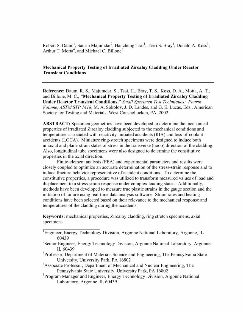
Robert S. Daum1, Saurin Majumdar2, Hanchung Tsai1, Terri S. Bray1, Donald A. Koss3, Arthur T. Motta4, and Michael C. Billone5
Mechanical Property Testing of Irradiated Zircaloy Cladding Under Reactor Transient Conditions Reference: Daum, R. S., Majumdar, S., Tsai, H., Bray, T. S., Koss, D. A., Motta, A. T., and Billone, M. C., “Mechanical Property Testing of Irradiated Zircaloy Cladding Under Reactor Transient Conditions,” Small Specimen Test Techniques: Fourth Volume, ASTM STP 1418, M. A. Sokolov, J. D. Landes, and G. E. Lucas, Eds., American Society for Testing and Materials, West Conshohocken, PA, 2002. ABSTRACT: Specimen geometries have been developed to determine the mechanical properties of irradiated Zircaloy cladding subjected to the mechanical conditions and temperatures associated with reactivity-initiated accidents (RIA) and loss-of-coolant accidents (LOCA). Miniature ring-stretch specimens were designed to induce both uniaxial and plane-strain states of stress in the transverse (hoop) direction of the cladding. Also, longitudinal tube specimens were also designed to determine the constitutive properties in the axial direction.
Finite-element analysis (FEA) and experimental parameters and results were closely coupled to optimize an accurate determination of the stress-strain response and to induce fracture behavior representative of accident conditions. To determine the constitutive properties, a procedure was utilized to transform measured values of load and displacement to a stress-strain response under complex loading states. Additionally, methods have been developed to measure true plastic strains in the gauge section and the initiation of failure using real-time data analysis software. Strain rates and heating conditions have been selected based on their relevance to the mechanical response and temperatures of the cladding during the accidents. Keywords: mechanical properties, Zircaloy cladding, ring stretch specimens, axial specimens ________________________ 1Engineer, Energy Technology Division, Argonne National Laboratory, Argonne, IL
60439 2Senior Engineer, Energy Technology Division, Argonne National Laboratory, Argonne,
IL 60439 3Professor, Department of Materials Science and Engineering, The Pennsylvania State
University, University Park, PA 16802 4Associate Professor, Department of Mechanical and Nuclear Engineering, The
Pennsylvania State University, University Park, PA 16802 5Program Manager and Engineer, Energy Technology Division, Argonne National
Laboratory, Argonne, IL 60439

Introduction The mechanical behavior of fuel cladding materials in light water reactors is degraded during steady state operation, through the mechanisms of oxidation, hydriding, and irradiation damage. Currently, utilities have been increasing the average discharge burnup of the fuel assemblies in an effort to reduce costs, outage times, and volume of waste associated with core reloads. However, the increased reactor exposure associated with higher fuel burnups results in additional cladding degradation. Also, utilities are increasing outlet coolant temperatures to improve thermal efficiency, which increases oxidation and hydrogen pickup. This increased degradation may increase the likelihood of cladding failure during design basis accidents (DBA). Cladding failure and subsequent fuel dispersal in the coolant are concerns during transient events, including the reactivity-initiated accident (RIA) and loss-of-coolant accident (LOCA). Therefore, international regulatory agencies and utilities have initiated experimental programs to determine the mechanical behavior of fuel cladding under RIA- and LOCA-type conditions; the results of these programs will be used to update fuel/cladding behavior databases and computer models, to improve predictions of deformation, and to help establish failure criteria.
This paper reports the techniques and procedures for determining both the constitutive properties and the failure behavior of cladding after irradiation to high fuel burnups. To accomplish this, we use miniature specimen geometries subjected to the loading and thermal conditions associated with RIA and LOCA transients. In this paper we discuss specimen geometries, procedures for determining constitutive properties, measurement techniques and experimental results, definitions of critical strains, equipment for specimen loading and heating, real-time data analysis package, and preparation of irradiated cladding and specimen fabrication.
Background Zirconium-based alloys (e.g., Zircaloy) are used for fuel cladding because of their low neutron absorption coefficient, good resistance to high temperature corrosion, and adequate mechanical strength and thermal conductivity. Because zirconium and its alloys have a hexagonal closed-packed structure, mechanical strength and ductility differ in the transverse and longitudinal directions. This anisotropy is further enhanced during processing in which cladding tubes are extruded, resulting in a texture, where the basal poles are preferentially aligned at a 30-40o angle from the radial direction. Therefore, it is necessary to determine the mechanical behavior in both the transverse and longitudinal directions.
Existing mechanical property databases for Zircaloy include data from biaxial tube burst, axial tensile, and ring tensile tests for cladding irradiated up to about 60 GWd/MTU (≈ 1.2 x 1026 n/m2 fast [E > 1 MeV] neutron fluence) [1,2]. However, the database for cladding irradiated to high fuel burnup is not extensive with regard to temperature and strain rates. Also, most of the tensile data is in the axial direction and the quality of the ring tensile data is suspect. During LOCA loading, which is dominated by gas pressurization, the stress ratio (hoop stress/axial stress = σθ/σz) has an approximate value of two and most of the deformation is in the hoop direction. For RIA loading, the stress ratio is expected to be in the range 1 ≤ (σθ/σz) ≤ 2 due to friction
effects caused by fuel pellet-cladding mechanical interaction (PCMI). Therefore, it is essential to improve the quality of database to include accurate hoop properties and to broaden the investigation of highly degraded cladding, taking into account the combined effects of oxidation, hydriding, and radiation damage. Specimen Geometries
Three types of specimens are used to impose a range of deformation paths on the cladding. Utilizing the results of previous studies [3] for testing tubing, the first specimen type has a modified ring geometry subjected to uniaxial tension, and in which the principal stress is in the hoop direction of the cladding. In addition, an axial specimen geometry, where the principal stress is in the longitudinal direction of the cladding, has also been used to determine constitutive properties. In order to characterize failure, this study adapts a plane-strain state of stress [4-6] to determine the cladding fracture behavior under near plane-strain tension in the hoop direction of the cladding.
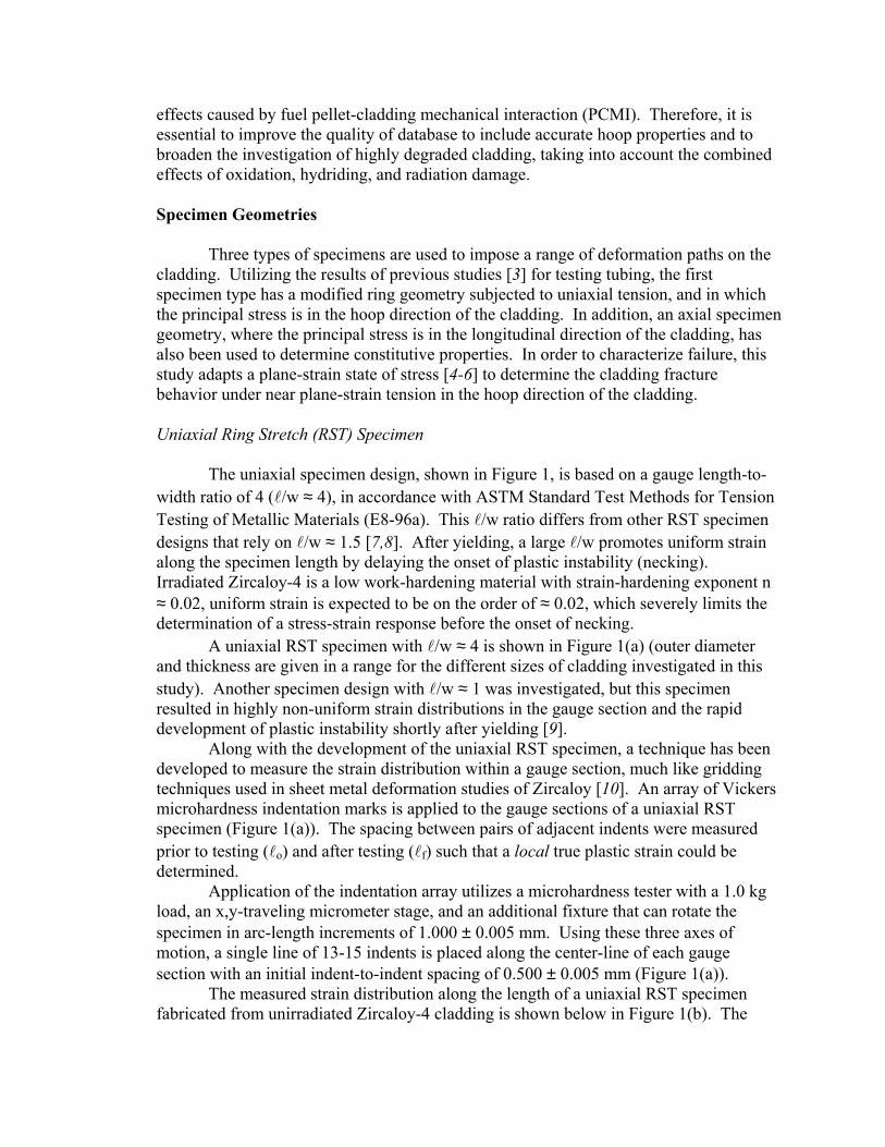
Uniaxial Ring Stretch (RST) Specimen The uniaxial specimen design, shown in Figure 1, is based on a gauge length-to-width ratio of 4 (l/w ≈ 4), in accordance with ASTM Standard Test Methods for Tension Testing of Metallic Materials (E8-96a). This l/w ratio differs from other RST specimen designs that rely on l/w ≈ 1.5 [7,8]. After yielding, a large l/w promotes uniform strain along the specimen length by delaying the onset of plastic instability (necking). Irradiated Zircaloy-4 is a low work-hardening material with strain-hardening exponent n ≈ 0.02, uniform strain is expected to be on the order of ≈ 0.02, which severely limits the determination of a stress-strain response before the onset of necking. A uniaxial RST specimen with l/w ≈ 4 is shown in Figure 1(a) (outer diameter and thickness are given in a range for the different sizes of cladding investigated in this study). Another specimen design with l/w ≈ 1 was investigated, but this specimen resulted in highly non-uniform strain distributions in the gauge section and the rapid development of plastic instability shortly after yielding [9].
Along with the development of the uniaxial RST specimen, a technique has been developed to measure the strain distribution within a gauge section, much like gridding techniques used in sheet metal deformation studies of Zircaloy [10]. An array of Vickers microhardness indentation marks is applied to the gauge sections of a uniaxial RST specimen (Figure 1(a)). The spacing between pairs of adjacent indents were measured prior to testing (lo) and after testing (lf) such that a local true plastic strain could be determined.
Application of the indentation array utilizes a microhardness tester with a 1.0 kg load, an x,y-traveling micrometer stage, and an additional fixture that can rotate the specimen in arc-length increments of 1.000 ± 0.005 mm. Using these three axes of motion, a single line of 13-15 indents is placed along the center-line of each gauge section with an initial indent-to-indent spacing of 0.500 ± 0.005 mm (Figure 1(a)).
The measured strain distribution along the length of a uniaxial RST specimen fabricated from unirradiated Zircaloy-4 cladding is shown below in Figure 1(b). The
(a)
lo = 0.50
8X R1.020
1.0206.0204.060
2.540
1.270
0.5600.710
9.500 10.900
-0.2
-0.1
0
0.1
0.2
0.3
0.4
0.5
0.6
-4 -3 -2 -1 0 1 2 3 4
True
Maj
or S
trai
n
Gauge Length Position (mm)
%STRAIN5Uniform
52Fracture
Room Tem peratureUniaxial RST Specimen
Gauge LengthFillet-to-Fillet
(b)
Figure 1: (a) a schematic diagram of uniaxial RST specimen with an array of
microhardness indents (dimensions in mm; not to scale) and (b) measured strain distribution at specimen fracture as determined from indent-to-indent spacing
entire gauge shows a uniform strain of approximately 5 ± 1%, as shown by the regions of constant strain. The large strain peak at a position of –1.25 mm shows the development of localized necking near the fracture surface. Therefore, compared to specimens with short gauge lengths that neck soon after yielding, this specimen design is better suited for determining the constitutive stress-strain properties.
The data in Figure 1(b) shows that specimen necking and fracture occur near the end of the gauge section (defined by the fillet); as will be discussed later in this paper, this failure occurs because of stress concentration, material anisotropy, and friction. FEA [9] indicates that the uniaxial RST and flat sheet uniaxial specimens behave similarly in the absence of friction. In both flat and RST specimens subjected to a uniaxial state of stress, failure is localized near the fillet.
Unlike the failure of irradiated cladding during an RIA event in which the fracture path is through the cladding thickness, the fracture of the uniaxial RST specimen occurs

along planes inclined across the specimen width [4]. In previous studies of unirradiated Zircaloy-4 subjected to uniaxial tension [4,9], the values of R and P,
thickness
axialRεε= and
thickness
transversePεε= (1)
were found to be 2.3 and 1.3, respectively. This implies that, under uniaxial tension, through-thickness slip is more difficult than through-width slip. Under uniaxial tension, Zircaloy-4 specimens tend to fail by shear across the width, unlike the through-thickness fracture that would occur during an RIA event. The onset of a localized necking instability has been analyzed by Chan and co-workers [11] such that necking will occur along slip bands at 40o from the principal stress, which has been confirmed experimentally using the uniaxial RST specimen [4]. Axial Tube Specimen Because of the plastic anisotropy of cladding tubes, it is also necessary to determine the constitutive stress-strain and deformation properties in the longitudinal (axial) direction, in addition to the hoop direction. The gauge length-to-width ratio (l/w) ≥ 4 was also chosen for maximizing uniform strain and deriving a constitutive stress-strain response; the design is shown in Figure 2 and has (l/w) ≈ 10. However, due to the limited amount and high dose rates of irradiated cladding, the design of the axial tube specimen must minimize material usage to maximize the number of specimens and limit dose to operators. From the results of Equation (1), we can see that R/P = 1.8 (plastic anisotropy, R/P=εaxial/εtransverse), which indicates that axial elongation will be significantly greater than transverse elongation.
2.540 8X R0.762
76.2
34.3
25.4
4.750 5.450 0.560
0.710
9.500 10.900
Figure 2: Axial tube specimen design (dimensions in mm; not to scale) Determination of Constitutive Properties using Uniaxial RST and Axial Tube Specimens In order to determine the constitutive stress-strain response of uniaxial RST specimens, a procedure has been developed using FEA to determine an effective gauge length and a load-correction factor to account for the interaction between the specimen and loading grips. Typical load-displacement responses for the uniaxial RST and axial tube specimens are shown in Figure 3.

From the load-displacement data (Figure 3(a)) of the uniaxial RST specimen, the “apparent” engineering stress (Sapparent) is obtained based on the load (P) applied to two gauge sections with an average width and thickness, assuming symmetric loading. The “actual” engineering stress (Sactual) is calculated by multiplying Sapparent by a correction factor (derived from FEA) to correct for the reaction force of the loading grips on the gauge section; nominal values of this correction factor range from 1.1 to 1.4 depending on the clearance between the gauge section and loading grips (described in later section).
-0.2
0
0.2
0.4
0.6
0.8
0 0.2 0.4 0.6 0.8 1 1.2
Load
Cel
l Rea
ding
(kN
)
Actuator Displacement (mm)
δP
δE
Zircaloy-4Uniaxial RST SpecimenRoom Temperature
(a)
-0.5
0
0.5
1
1.5
2
2.5
3
3.5
-2 0 2 4 6 8 10
Load
Cel
l Rea
ding
(kN
)
Actuator Displacement (mm)
Room Temperature
10-3 sec-1
Zircaloy-4
Axial TubeSpecim en
Uniaxial RSTSpecim en
(b)
Figure 3: (a) load-displacement response for a uniaxial RST specimen with definitions of δp and δE and (b) load-displacement response of uniaxial RST and axial tube specimens
Also from Figure 3(a), the plastic displacement (δP) is obtained by subtracting the elastic displacement (δE, derived from the linear portion of the load-displacement curve assuming a value of the “effective” elastic modulus, E). The plastic component of engineering strain (eP) is based on δP and an “effective” gauge length (leff), which is

derived from FEA-based numerical testing. The elastic component (eE) is calculated from the elastic component of Sactual and E. A similar procedure is utilized to calculate an engineering stress-strain response for the axial tube specimen; however, for this specimen, there are no complications due to specimen-loading grip interactions so that Sapparent = Sactual. Therefore, an engineering stress-strain response is generated for both uniaxial RST and axial tube specimens.
To validate the techniques and procedures for determining the engineering stress-strain properties of an isotropic material, 304 stainless steel (304SS), has been tested using uniaxial RST and axial tube specimens geometries. Figure 4 shows the engineering stress-strain curves for transverse and longitudinal specimens, determined on the basis of isotropic plasticity, for 304SS axial tube and uniaxial RST specimens as a function of coefficient of friction (µ). The circumferential stress-strain curve is shown to be relatively insensitive to coefficient of friction in the range 0≤µ≤0.05; actual values of µ are estimated to be approximately 0.03 at room temperature. The uncorrected data of Figure 4 refers to an engineering stress-strain curve obtained by using the uncorrected load cell response to determine an engineering stress and the original gauge length of 4.06 mm (refer to Figure 1) to determine an engineering strain (e). The corrected data of Figure 4 takes into account the interaction between the uniaxial RST specimen and loading grips. Additionally, the corrected engineering strain is calculated by dividing the instantaneous δP-value from the load-displacement response by leff (≈ 5.72 mm for the specific cladding dimensions used in this study); leff has been determined by dividing the final plastic displacement (δP) by the plastic strain representing the calculated cross-sectional-average plastic strain at the mid-section of the gauge. For 0<µ<0.05, the corrected RST data coincides with the axial tube data, as expected for isotropic 304SS. Thus, this exercise validates the procedure developed for obtaining a stress-strain curve in the circumferential direction from the measured load-displacement data.
0
200
400
600
800
0
20
40
60
80
100
-20 0 20 40 60 80
Raw Data
µ=0
µ=0.05
µ=0.1
µ=0.2
Eng
inee
ring
Str
ess
(MP
a)
Engineering S
tress (ksi)
Engineering Strain (%)
UncorrectedUniaxial RST
Axial Tube
CorrectedUniaxial RST
Suts
Sys
304SS
Figure 4: Curves of uncorrected and corrected engineering stress [as a function of coefficient of friction (µ)] versus engineering strain for 304SS tubing derived from testing
uniaxial RST and axial tube (also shown) specimens

By only considering values of Sactual and eP after the yield point (defined by Sys in Figure 4) and before localized necking (assuming the onset of necking occurs at the ultimate strength [Sactual]max or Suts, as shown in Figure 4), the true stress (σ) and true strain (ε) are calculated from the transformation equations:
ε=ln(1+eP) and σ=Sactual(1+eP) (2).
The true stress-strain response is empirically modeled using the Power Law (σ=σo+Kεn) for strains between the yield and ultimate strengths, where σo is the yield strength, K is the strength coefficient, and n is the strain-hardening exponent. These parameters are used in computer codes for modeling the mechanical response of the cladding under RIA and LOCA transients.
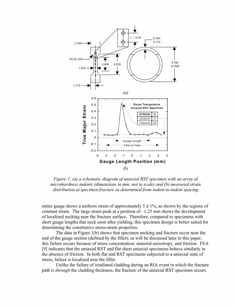
Using this procedure validated for an isotropic material, we have tested unirradiated (and anisotropic) Zircaloy-4 tubing. Figure 5 shows the results of load-displacement transformation to engineering stress-strain for both uniaxial RST and axial tube specimens. Also shown, the axial uniform elongation satisfies the criterion εu ≈ n, where n is strain-hardening exponent. On the other hand, the n-value for the circumferential curve is 0.06, but onset of failure occurs at 2% plastic strain. However, according to the strain distribution of Figure 1(b), the gauge section has deformed uniformly to approximately 0.05, which is consistent with the εu ≈ n. Finite-element analysis suggests that the stress concentration effects at the junction of fillet with the gauge section causes the specimen to fail prematurely at the fillet. Thus, the stress and plastic strain at peak load for the uniaxial RST specimen are lower bounds to the ultimate tensile strength and uniform elongation. However, a sufficient portion of the initial circumferential (hoop) flow stress curve has been recorded from the load and plastic displacement reponse so that an n-value (=0.06) can be determined with confidence (Figure 5(b)). The dashed line (Figure 5(a)) is drawn with this value of the exponent up to a plastic strain of 6%. The estimated circumferential ultimate tensile strength and uniform elongation are tabulated in Figure 5(a) and are based on this dashed curve. It is suggested that the circumferential stress-strain curve would have followed the dashed curve had the specimen not failed prematurely at the fillet junction.
Therefore, it is possible to estimate the circumferential ultimate tensile strength and uniform elongation by using the criterion εu ≈ n, which is also satisfied by the axial tensile curve. The circumferential yield and flow stresses are ~ 10% higher than the axial yield and flow stresses. The estimated uniform elongations in the circumferential and axial directions are 6 and 7%, respectively.
Plane-Strain RST Specimen As mentioned earlier, irradiated fuel cladding fails under RIA-type loading by through-thickness slip and under a biaxial state of stress. In contrast, in the absence of any constraint across the gauge width, the uniaxial RST specimen fails by slip across the gauge width such that extensive specimen width contraction occurs, unlike RIA-type failures. Therefore, an additional specimen design has been developed to impose the near plane-strain state of stress to simulate cladding deformation with hoop extension
0
200
400
600
800
0
20
40
60
80
100
120
0 2 4 6 8 10 12 14Eng
inee
ring
Str
ess
(MP
a)
Engineering S
tress (ksi)
Engineering Strain (%)
Uniaxial RSTAxial Tube
Uniaxial RST(Estimated)
eu (%)S
uts (MPa)S
ys (MPa)
7706578Axial Tube
> 2> 716638Uniaxial RST
6737638Est. Uniaxial RST
Zircaloy-4
(a)
400
500
600
700
800
900
1000
60
70
80
90
100
0.001 0.01 0.1 1 10 100
Axial Tube SpecimenUniaxial RST Specimen
True
Str
ess
(MP
a) True Stress (ksi)
True Plastic Strain (%)
n = 0.06
n = 0.07 10-3 sec-1
Room Temperature
Zircaloy-4
(b)
Figure 5: (a) derived (solid lines) and estimated (dashed line for uniaxial RST specimen)
engineering stress-strain curves for Zircaloy-4 from testing of uniaxial RST and axial tube specimens and (b) the same data plotted as true stress-true plastic strain curves
9.500 10.90
0.560 0.710
12 70
8X R1.02
2.16
6 35
Figure 6: Plane-Strain RST Specimen design (dimensions in mm; not to scale)
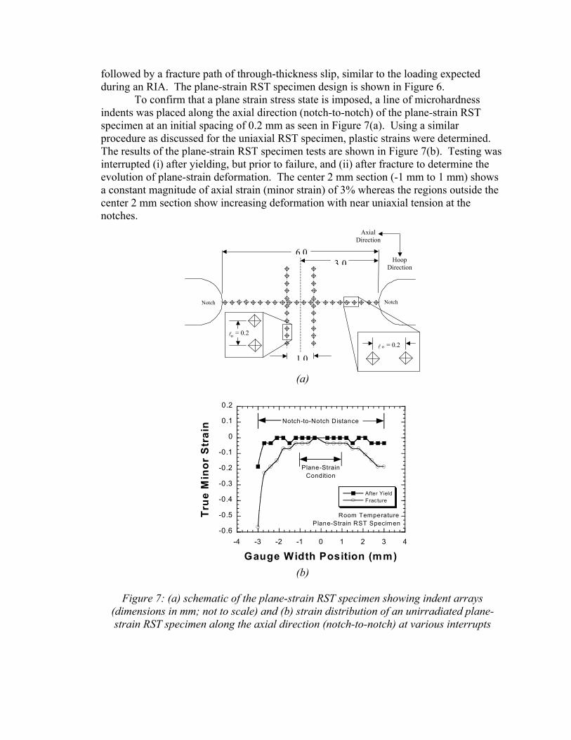
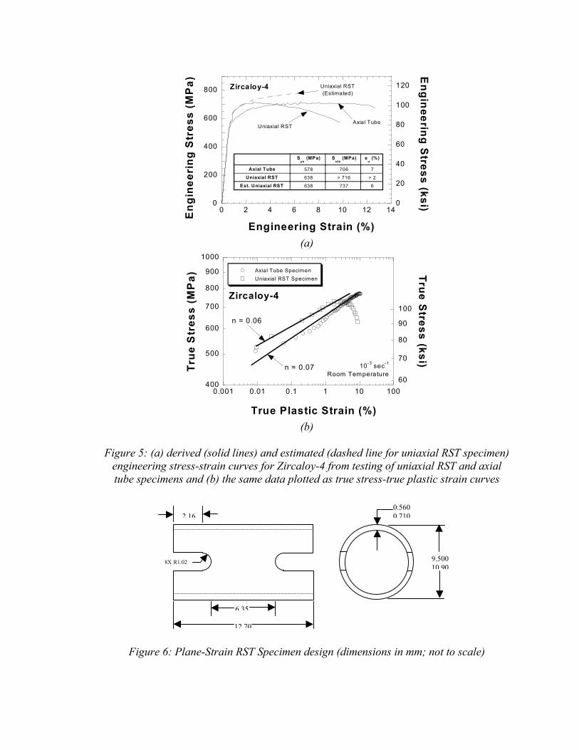
followed by a fracture path of through-thickness slip, similar to the loading expected during an RIA. The plane-strain RST specimen design is shown in Figure 6.
To confirm that a plane strain stress state is imposed, a line of microhardness indents was placed along the axial direction (notch-to-notch) of the plane-strain RST specimen at an initial spacing of 0.2 mm as seen in Figure 7(a). Using a similar procedure as discussed for the uniaxial RST specimen, plastic strains were determined. The results of the plane-strain RST specimen tests are shown in Figure 7(b). Testing was interrupted (i) after yielding, but prior to failure, and (ii) after fracture to determine the evolution of plane-strain deformation. The center 2 mm section (-1 mm to 1 mm) shows a constant magnitude of axial strain (minor strain) of 3% whereas the regions outside the center 2 mm section show increasing deformation with near uniaxial tension at the notches.
(a)
6 0
1 0
3 0
l o = 0.2
Notch
= 0.2
Axial Direction
HoopDirection
l o
Notch
-0.6
-0.5
-0.4
-0.3
-0.2
-0.1
0
0.1
0.2
-4 -3 -2 -1 0 1 2 3 4
After YieldFracture
True
Min
or S
trai
n
Gauge Width Position (mm)
Room TemperaturePlane-Strain RST Specimen
Notch-to-Notch Distance
Plane-StrainCondition
(b)
Figure 7: (a) schematic of the plane-strain RST specimen showing indent arrays
(dimensions in mm; not to scale) and (b) strain distribution of an unirradiated plane-strain RST specimen along the axial direction (notch-to-notch) at various interrupts
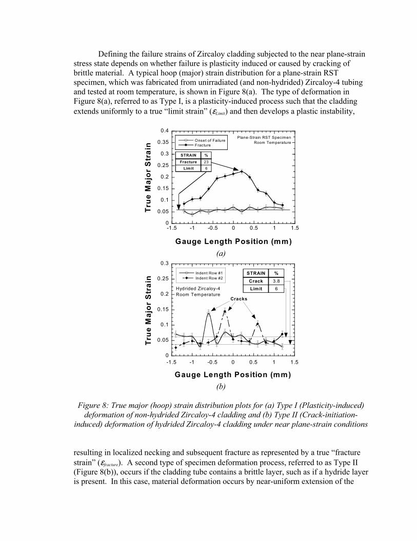
Defining the failure strains of Zircaloy cladding subjected to the near plane-strain stress state depends on whether failure is plasticity induced or caused by cracking of brittle material. A typical hoop (major) strain distribution for a plane-strain RST specimen, which was fabricated from unirradiated (and non-hydrided) Zircaloy-4 tubing and tested at room temperature, is shown in Figure 8(a). The type of deformation in Figure 8(a), referred to as Type I, is a plasticity-induced process such that the cladding extends uniformly to a true “limit strain” (εLimit) and then develops a plastic instability,
0
0.05
0.1
0.15
0.2
0.25
0.3
0.35
0.4
-1.5 -1 -0.5 0 0.5 1 1.5
Onset of FailureFracture
True
Maj
or S
trai
n
Gauge Length Position (mm)
Plane-Strain RST SpecimenRoom Temperature
%STRAIN23Fracture6Limit
(a)
0
0.05
0.1
0.15
0.2
0.25
0.3
-1.5 -1 -0.5 0 0.5 1 1.5
Indent Row #1Indent Row #2
True
Maj
or S
trai
n
Gauge Length Position (mm)
%STRAIN3.8Crack6LimitHydrided Zircaloy-4
Room TemperatureCracks
(b)
Figure 8: True major (hoop) strain distribution plots for (a) Type I (Plasticity-induced)
deformation of non-hydrided Zircaloy-4 cladding and (b) Type II (Crack-initiation-induced) deformation of hydrided Zircaloy-4 cladding under near plane-strain conditions
resulting in localized necking and subsequent fracture as represented by a true “fracture strain” (εfracture). A second type of specimen deformation process, referred to as Type II (Figure 8(b)), occurs if the cladding tube contains a brittle layer, such as if a hydride layer is present. In this case, material deformation occurs by near-uniform extension of the
cladding until microcracks form at a “crack-initiation strain” (εcrack). Once cracks initiate, the material adjacent to the free surface of the crack flank ceases to deform, “freezing” that material at the initiation strain (εcrack). However, material distant from the crack continues to deform to a limit strain (εLimit). At that level of strain, deformation localizes in the form of crack opening displacements (large peak strains in Figure 8(b)). Initial results indicate that Type II cracking is found in artificially-hydrided, unirradiated cladding and is expected to occur in irradiated cladding. A method of determining εLimit has been developed using numerical integration. For each row of indents, the strain at a given position is summed at intervals of 0.2 mm. The limit strain is then calculated using the following equation:
∑
∑∆
∆⋅=
ii
iii
Limit y
y )(εε (3)
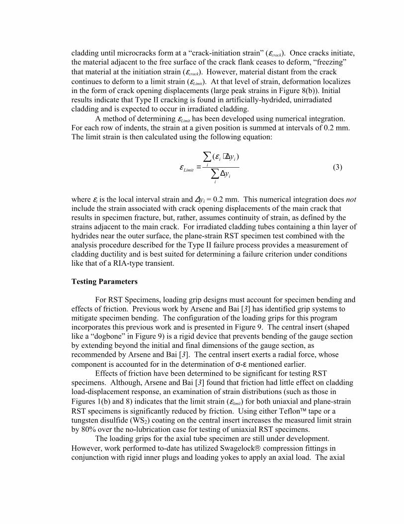
where εi is the local interval strain and ∆yi = 0.2 mm. This numerical integration does not include the strain associated with crack opening displacements of the main crack that results in specimen fracture, but, rather, assumes continuity of strain, as defined by the strains adjacent to the main crack. For irradiated cladding tubes containing a thin layer of hydrides near the outer surface, the plane-strain RST specimen test combined with the analysis procedure described for the Type II failure process provides a measurement of cladding ductility and is best suited for determining a failure criterion under conditions like that of a RIA-type transient. Testing Parameters For RST Specimens, loading grip designs must account for specimen bending and effects of friction. Previous work by Arsene and Bai [3] has identified grip systems to mitigate specimen bending. The configuration of the loading grips for this program incorporates this previous work and is presented in Figure 9. The central insert (shaped like a “dogbone” in Figure 9) is a rigid device that prevents bending of the gauge section by extending beyond the initial and final dimensions of the gauge section, as recommended by Arsene and Bai [3]. The central insert exerts a radial force, whose component is accounted for in the determination of σ-ε mentioned earlier. Effects of friction have been determined to be significant for testing RST specimens. Although, Arsene and Bai [3] found that friction had little effect on cladding load-displacement response, an examination of strain distributions (such as those in Figures 1(b) and 8) indicates that the limit strain (εlimit) for both uniaxial and plane-strain RST specimens is significantly reduced by friction. Using either Teflon tape or a tungsten disulfide (WS2) coating on the central insert increases the measured limit strain by 80% over the no-lubrication case for testing of uniaxial RST specimens. The loading grips for the axial tube specimen are still under development. However, work performed to-date has utilized Swagelock compression fittings in conjunction with rigid inner plugs and loading yokes to apply an axial load. The axial
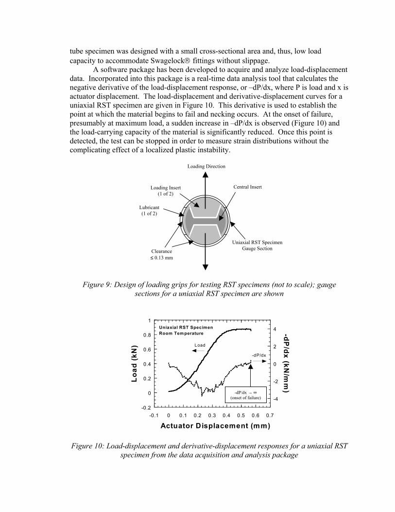
tube specimen was designed with a small cross-sectional area and, thus, low load capacity to accommodate Swagelock fittings without slippage. A software package has been developed to acquire and analyze load-displacement data. Incorporated into this package is a real-time data analysis tool that calculates the negative derivative of the load-displacement response, or –dP/dx, where P is load and x is actuator displacement. The load-displacement and derivative-displacement curves for a uniaxial RST specimen are given in Figure 10. This derivative is used to establish the point at which the material begins to fail and necking occurs. At the onset of failure, presumably at maximum load, a sudden increase in –dP/dx is observed (Figure 10) and the load-carrying capacity of the material is significantly reduced. Once this point is detected, the test can be stopped in order to measure strain distributions without the complicating effect of a localized plastic instability.
Loading Direction
Clearance ≤ 0.13 mm
Lubrican t(1 of 2)
Central Insert
Uniaxial RST Specimen Gauge Section
Loading In ert s(1 of 2)
Figure 9: Design of loading grips for testing RST specimens (not to scale); gauge
sections for a uniaxial RST specimen are shown
-0.2
0
0.2
0.4
0.6
0.8
1
-4
-2
0
2
4
-0.1 0 0.1 0.2 0.3 0.4
Load
(kN
)
-dP/dx (kN
/mm
)
Actuator Displacem
Uniaxial RST SpecimenRoom Tem perature
Load
-dP/dx
Figure 10: Load-displacement and derivative-displ
specimen from the data acquisition
-dP/dx → ∞ (onset of failure)
0.5 0.6 0.7
ent (mm)
acement responses for a uniaxial RST and analysis package

Strain rates have been chosen that are relevant to either RIA or LOCA conditions. Specifically, a strain rate of 10-3/s was chosen for LOCA-relevant testing, based on an estimate of load-controlled conditions during pressurization of the cladding due to fill gas (He) and fission gas release from the fuel pellets; note that the initial fill gas pressure is significant (up to 3 MPa at room temperature for Zircaloy-4). Whereas, a strain rate of 1/s for RIA-relevant testing is based on a combination of load- and strain-controlled loading from rapid expansion of the fuel pellet causing pellet-clad mechanical interaction (PCMI) with an associated friction coefficient and gas loading from sudden release of fission gases [12]; note that the strain rate during an RIA can be > 1/s. Temperatures and heating rates have been chosen to determine the temperature-dependence on the mechanical properties of cladding materials while relevant to the thermal conditions of LOCA-type and RIA-type transients. For RIA-relevant testing, temperatures range from 25 to 400oC (298-673K) and a heating rate of approximately 100oC/sec (relevant only to pressurized water reactors) [12,13]. For LOCA-relevant testing, temperatures range from 25 to 800oC and a heating rate of 5oC/sec. Thermal annealing of irradiation damage and cold-work during testing occurs if the material is kept for a significant time above a temperature between 600oC and 800oC, which causes the mechanical properties of irradiated cladding to approach that of unirradiated cladding at elevated temperatures [7]. Specimen Preparation for Irradiated Specimens In a hot cell, a 5-inch long section of cladding is placed in a nitric acid (HNO3) bath for 1-2 days to remove the fuel. Using a pair of diamond files, the oxide on the outer surface of the cladding is partially removed to establish an electrical circuit for specimen fabrication using an Electrical Disharge Machine (EDM). Particular care is taken not to remove any hydrides (in the form of circumferentially-oriented platelets near the outer surface) since the mechanical behavior of the cladding has been found to be greatly influenced by hydride content and distribution [14]. Grit paper is used to remove any machining burrs, potential flaws created during the EDM cutting, and roughness of the inner surface to limit friction effects. The dimensions of each specimen are measured to verify design specifications and determine gauge section dimensions for stress-strain calculations. RST specimens are placed in the microhardness tester in order to apply arrays of microhardness indents and to measure indent-to-indent spacings before testing. After testing the RST specimens, indent-to-indent spacings are again measured using the microhardness tester to determine plastic strains. Conclusions An experimental program has been initiated to investigate the mechanical properties in the longitudinal and transverse directions of high-burnup, light water reactor fuel cladding using small specimen geometries and minature loading fixtures. Testing conditions have been identified to generate data relevant to the loading and thermal conditions of reactivity-initiated accidents (RIA) and loss-of-coolant accidents (LOCA). To accomplish this task, the following issues have been addressed:
1. Specimen geometries have been optimized to determine the constitutive stress-strain properties of the cladding in both the hoop and axial directions. In contrast to other ring stretch specimen (RST) geometries that rely on short gauge lengths, the uniaxial RST specimen, based on a gauge length-to-width ratio of four, have been chosen to optimize uniform deformation for determination of stress-strain responses in the hoop direction. An axial tube specimen is also being used to determine constitutive properties in the axial direction of the cladding. 2. In order to determine the failure behavior of cladding under RIA-type conditions, a plane-strain RST specimen has been employed. Two modes of failure have been identified in Zircaloy cladding. A plasticity-induced deformation process (Type I) occurs in unirradiated cladding, whereas, failure involving crack initiation and extension due to crack-opening displacement (Type II) occurs in unirradiated cladding containing a hydride layer near the outer surface. It is expected that cladding irradiated to high fuel burnups, and which is heavily hydrided, will have limited ductility and fail by the Type II process. 3. Loading grips for testing RST specimens have been designed to mitigate bending effects and friction by utilizing a central insert coated with Teflon or tungsten disulfide. Both Finite Element Analyses and experimental results have confirmed that bending and friction significantly influence the determination of constitutive and deformation properties. 4. A data acquisition and analysis package has been developed to determine the onset of failure during testing of irradiated cladding. By determining the real-time first derivative (-dP/dx) of the load-displacement response, failure is defined at the point of load-loss capacity. This will allow the measurement of strains at the onset of failure without the complicating effects of strain accumulation during plastic instability. Acknowledgements This work was supported by the United States Nuclear Regulatory Commission, Office of Nuclear Regulatory Research. The authors would like to thank Iouri Prokofiev, William Kettman, David McGann, and David Pushis of the Irradiation Performance Section at Argonne National Laboratory for assisting in the development of equipment and experimental methods. References [1] Hagrman, D. L., Reyman, G. A., and Mason, R. E., “MATPRO-V.11 Revision 1: A
Hand Book of Materials Properties for Use in the Analysis of Light Water Reactor Fuel Rod Behavior”, NUREG/CR-0497 TREE-1280, Rev2, 1981.
[2] Garde, A. M., Smith, G. P., and Pirek, R. C., “Effects of Hydride Precipitate Localization and Neutron Fluence on the Ductility of Irradiated Zircaloy-4,” Zirconium in the Nuclear Industry: Eleventh International Symposium, ASTM STP 1295, E. R. Bradley and G. P. Sabol, Eds., American Society for Testing and Materials, p. 407-430, 1996.

[3] Arsene, S. and Bai, J., “A New Approach to Measuring Transverse Properties of Structural Tubing by a Ring Test”, Journal of Testing and Evaluation, Vol. 24 No. 6, p. 386-391, 1996.
[4] Link, T. M., Koss, D. A., and Motta, A. T., “Failure of Zircaloy Cladding under Transverse Plane-Strain Deformation”, Nuclear Engineering and Design, Vol. 186, p. 379-394, 1998.
[5] Wagoner, R. H., “Measurement and Analysis of Plane-Strain Work Hardening”, Metallurgical Transactions A, Vol. 11A, p. 165-175, 1980.
[6] Yunchang, F. and Koss, D. A., “The Influence of Multiaxial States of Stress on Hydrogen Embrittlement of Zirconium Alloy Sheet”, Metallurgical Transactions A, Vol. 16A, p. 675-681, 1985.
[7] Cazalis, B., “Zirconium Alloys Mechanical Properties: Summary of IPSN/Cadarache Program,” Mechanical Properties Experts Meeting, NRC Headquarters, Rockville, MD, October 26-27, 2000.
[8] Kitano, K., “Study on Mechanical Properties in Hoop Direction of Zircaloy Cladding,” Mechanical Properties Experts Meeting, NRC Headquarters, Rockville, MD, October 26-27, 2000.
[9] Bates, D. W., Koss, D. A., Motta, A. T., and Majumdar, S., “Influence of Specimen Design on the Deformation and Failure of Zircaloy Cladding”, Proceedings of the 2000 International Topical Meeting on LWR Fuel Performance, Park City, UT, p. 1201-1210, April 10-13, 2000.
[10] Mahmood, S. T. and Murty, K. L., “Localized Plastic Flow, Anisotropic Mechanical Properties and Crystallographic Texture in Zircaloy Sheet”, Journal of Materials Engineering, Vol. 11, No. 4, p. 315-329, 1989.
[11] Chan, K. S., Koss, D. A., and Ghosh, A. K., “Localized Necking of Sheet at Negative Minor Strains,” Metallurgical Transactions A, Vol. 15A, p. 323, 1984.
[12] Papin, J., Balourdet, M., Lemoine, F., Lamare, F., Frizonnet, J. M., and Schmitz, F., “French Studies on High-Burnup Fuel Transient Behavior Under RIA Conditions,” Nuclear Safety, Vol. 37, No. 4, p. 289-327, 1996.
[13] Meyer, R. O., McCardell, R. K., Chung, H. M., Diamond, D. J., and Scott, H. H., “A Regulatory Assessment of Test Data for Reactivity-Initiated Accidents”, Nuclear Safety, Vol. 37, No. 4, p. 271-288, 1996.
[14] Fuketa, T., Nakamura, T., Sasajima, H., Nagase, F., Uetsuka, H., Kikuchi, K, and Tomoyuki, A., “Behavior of PWR and BWR Fuels During Reactivity-Initiated Accident Conditions,” Proceedings of the 2000 International Topical Meeting on LWR Fuel Performance, Park City, UT, p. 1133-1147, April 10-13, 2000.