Embed Size (px)
Citation preview
INSTALLATION AND OPERATING MANUAL Translation of the original manual
Keep for future use! This operating manual must be strictly observed before transport, installation, operation and maintenance
Subject to change without notice. Reproduction is generally permitted with indication of the source.
© Richter Chemie-Technik GmbH
9220-063-en Revision 10 Edition 03/2010
Series SCK
Mechanical Seal double, to DIN EN 12756

Series SCK, double mechanical seal to DIN EN 12756 Page 2
9220-063-en Revision 10 TM 7827 Edition 03/2010
List of Contents
List of Contents ........................................ 2
Relevant documents ................................. 2
1 Technical data ...................................... 2
2 Safety, transport and storage ............. 3 2.1 Intended use ................................................ 3
3 Product description ............................. 3
4 Commissioning / Shutdown ................ 3 4.1 Initial commissioning ................................... 3 4.2 Mechanical seals ......................................... 3
4.2.1 Use in an explosive area ................................. 3 4.2.2 Double mechanical seal to DIN EN 12756 ..... 3
4.3 Inadmissible modes of operation and their consequences (examples) .......................... 4
5 Maintenance ......................................... 4 5.1 Dismantling of double mechanical seal to
DIN EN 12756 ............................................. 4 5.1.1 Dismantling of back plate, impeller and mating
ring carrier ....................................................... 4 5.1.2 Dismantling of shaft sleeve .............................. 5
5.3 Notes on assembly ...................................... 5
6 Faults .................................................... 5
7 Sectional drawing ................................ 6 7.1 Legend ......................................................... 6 7.2 Double mechanical seal to DIN EN 12756 .. 6
Relevant documents ♦ Operating manual SCK long-life grease and oil
bath lubrication 9220-050-en
Operating manual mechanical seal of the manufacturer
1 Technical data
Manufacturer : Richter Chemie-Technik GmbH Otto-Schott-Str. 2 D-47906 Kempen Telephone: +49 (0) 2152 146-0 Fax: +49 (0) 2152 146-190 E-Mail: [email protected]: http://www.richter-ct.com
Authorised person acc. to machinery directive 2006/42/EG: Gregor Kleining
Designation : Series SCK, mechanical seal:♦ double, to DIN EN 12756
Materials : Seal housing: Stainless steel Wetted parts:Mechanical seal: SSiC, carbon, Al2O3, PTFE, FKM,
FFKM etc., see also data sheet
Temperature range : see installation and operating manual SCK, Section 1
Temperature classes : see installation and operating manual SCK, Section 2.6.7.

Series SCK, double mechanical seal to DIN EN 12756 Page 3
9220-063-en Revision 10 TM 7827 Edition 03/2010
2 Safety, transport and storage The relevant sections in the adjacent installation and operating manuals apply to safety, transport and storage. This installation and operating manual is only valid in conjunction with the installation and operating manuals of SCK long-life grease and oil bath lubrication
9220-050-en
2.1 Intended use Double mechanical seals for plastic-lined pumps of the series SCK are suitable for the use of aggressive, toxic, pure and inflammable media. The instructions contained in the operating manual or contractual documentation are to be observed, if necessary consult the manufacturer. All the important features are documented in the data sheet included in the scope of delivery.
3 Product description For a product description of the pump, see the installation and operating manual for the SCK series. Section 7.2The sectional drawing shows a double mechanical seal to DIN EN 12756.
All components which come into contact with the process medium are either lined with plastic or are made of other resistant materials, e.g. silicon carbide.
4 Commissioning / Shutdown
4.1 Initial commissioning See installation and operating manual for the series SCK.
4.2 Mechanical seals The design and material combination are specified in the data sheet.
The proper condition of the components and the protective facilities must be ensured to prevent any risk from escaping medium. The regulations and recommendations of the mechanical seal manufacturer must always be observed.
4.2.1 Use in an explosive area
Use in an explosive area means that only mechanical seals may be employed which permit observation of temperature.
The operating manual of the respective mechanical seal manufacturer is an integral part of this general operating manual. This permits, amongst other things, the calculation of the expected surface temperature at the mechanical seal. The suitability for the permissible temperature class as per ATEX is hereby given.
CAUTION:The permissible temperature class of the complete unit (pump, mechanical seal, coupling, motor) is determined by the lowest temperature class of the individual components. Example: Pump T4, mechanical seal T3,
coupling T4, motor T4 In both cases the unit may only be used in atmospheres which may ignite above the temperature class T3, i.e. >200 °C (>392°F).
4.2.2 Double mechanical seal to DIN EN 12756
A pump fitted with a double mechanical seal must not be filled with a product before the pressurisation system provided has been started up. Otherwise damage could occur, e.g. opening of the wetted sealing gap, before start-up. To guarantee safe operation, the pressure of the barrier fluid must be 1-2 bar above the pressure of the process medium at the mechanical seal at Q=0 m3/h. It must be ensured that the sealing pressure does not exceed the admissible pressure of the mechanical seal used. The required sealing pressure can be determined as follows: 2/3 of the delivery pressure at Q = 0 m3/h + supply pressure + 1 - 2 bar safety margin
Series SCK, double mechanical seal to DIN EN 12756 Page 4
9220-063-en Revision 10 TM 7827 Edition 03/2010
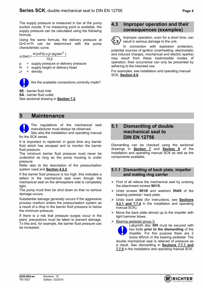
The supply pressure is measured in bar at the pump suction nozzle. If no measuring point is available, the supply pressure can be calculated using the following formula. Using the same formula, the delivery pressure at Q=0 m3/h can be determined with the pump characteristic curve.
2,10)(kg/dm x(mFS) H
=(bar) p3ρ
p = supply pressure or delivery pressure H = supply height or delivery head ρ = density
Are the available connections correctly made?
SE - barrier fluid inlet SA - barrier fluid outlet See sectional drawing in Section 7.2.
4.3 Improper operation and their consequences (examples) Improper operation, even for a short time, can result in serious damage to the unit. In connection with explosion protection,
potential sources of ignition (overheating, electrostatic and induced charges, mechanical and electric sparks) may result from these inadmissible modes of operation; their occurrence can only be prevented by adhering to the intended use. For examples, see installation and operating manual SCK, Section 6.6.
5 Maintenance The regulations of the mechanical seal manufacturer must always be observed. See also the installation and operating manual
for the SCK series. It is important to replenish in good time any barrier fluid which has escaped and to monitor the barrier fluid pressure. The minimum barrier fluid pressure must never be undershot as long as the pump housing is under pressure Refer also to the description of the pressurisation system used and Section 4.2.2.If the barrier fluid pressure is too high, this indicates a defect in the mechanical seal even though the mechanical seal on the atmosphere side is completely tight. The pump must then be shut down so that no serious damage occurs. Substantial damage generally occurs if the aggressive process medium enters the pressurisation system as a result of a drop in the barrier fluid pressure to below the minimum pressure. If there is a risk that pressure surges occur in the plant, precautions must be taken to prevent damage. To this end, for example, the barrier fluid pressure can be increased.
5.1 Dismantling of double mechanical seal to DIN EN 12756
Dismantling can be checked using the sectional drawings in Section 7 and Section 9 of the installation and operating manual SCK as well as the components available.
5.1.1 Dismantling of back plate, impeller and mating ring carrier
� First of all relieve the mechanical seal by undoing the attachment screws 901/5.
� Undo screws 901/6 and washers 554/6 of the bearing pedestal / back plate.
� Undo back plate (for instructions, see Sections 4.2.1 and 7.7.4 in the installation and operating manual SCK).
� Move the back plate almost up to the impeller with light hammer blows.
� Bearing pedestal group 3:Labyrinth disc 555 must be secured with two bolts prior to the dismantling of the impeller. For this purpose there are 2 bores Ø5mm in the bearing pedestal. The
double mechanical seal is relieved of pressure as a result. See dismantling in Sections 7.7.1 and 7.7.5 in the installation and operating manual SCK.

Series SCK, double mechanical seal to DIN EN 12756 Page 5
9220-063-en Revision 10 TM 7827 Edition 03/2010
� Undo impeller 230 with a strap wrench or assembly wrench. Right-hand thread.For assembly aid for impeller, see Section 10.1 in the installation and operating manual SCK. See also installation and operating manual SCK, Section 7.7.1.
� With some pump sizes the work sequence is to be repeated once or twice so that the cup springs 950/1 can be completely relieved without moving the shaft sleeve 524 in the rotating units 470 of the mechanical seal.
� Then completely remove the impeller 230.� Undo back plate (for instructions, see Sections
4.2.1 and 7.7.4 in the installation and operating manual SCK).
� It may happen that the mating ring carrier 476 is removed at the same time as the mating ring 475/1.
� If the mating ring 475/1 is replaced, remove the anti-torsion insert stud 560/3.
5.1.2 Dismantling of shaft sleeve
� Pull the shaft sleeve 524 with the rotating units 470/1 and 470/2 which are still installed off the shaft.
� When changing the rotating unit, observe the operating manual of the mechanical seal manufacturer.
� Remove seal housing 483.� Remove mating ring 475/2.
5.2 Notes on assembly ♦ Only use original spare parts. ♦ Do not use any defective parts as otherwise the
next damage is pre-programmed. ♦ The recommendations of the mechanical seal
manufacturer are to be observed. ♦ Bearing pedestal group 3:
Always make sure that when installing the mechanical seal the labyrinth disc is secured by 2 bolts. The bolts must be removed again after
assembly of the impeller. ♦ If the rotating units are moved by a key, the two
seal halves are to be pushed from both sides onto the shaft sleeve. Otherwise the secondary seal would be damaged on the sharp edges of the key groove.
♦ PTFE rings are often easier to install if they have been previously heated in hot water.
♦ The mating ring carrier 476 is designed with an anti-torsion insert for the wetted mating ring. It must be ensured that the mating ring is properly installed in this device.
♦ With some mechanical seal types the rotating units can be better pushed over the shaft sleeve when dismantled.
♦ Mount rotating unit 470/2 with pumping thread on the impeller side.
♦ The rotating units 470/1 and 470/2 must be flush with the key 940/2.
♦ When pushing on the mating ring 475/1, make sure that the position of the flat section matches that on the shaft.
6 Faults Faults may result from inadmissible modes of operation. Such inadmissible modes of operation – even brief ones – may cause
serious damage to the unit. In connection with explosion protection, potential sources of ignition (overheating, electrostatic and induced charges, mechanical and electric sparks) can result from these inadmissible modes of operation; their occurrence can only be prevented by adhering to the intended use.
Should there be any uncertainty about the remedy to be applied, please inquire at your in-house pump office or at the pump manufacturer's. See also Section 8 in the installation and operating manual of the SCK series.
Series SCK, double mechanical seal to DIN EN 12756 Page 6
9220-063-en Revision 10 TM 7827 Edition 03/2010
7 Sectional drawing
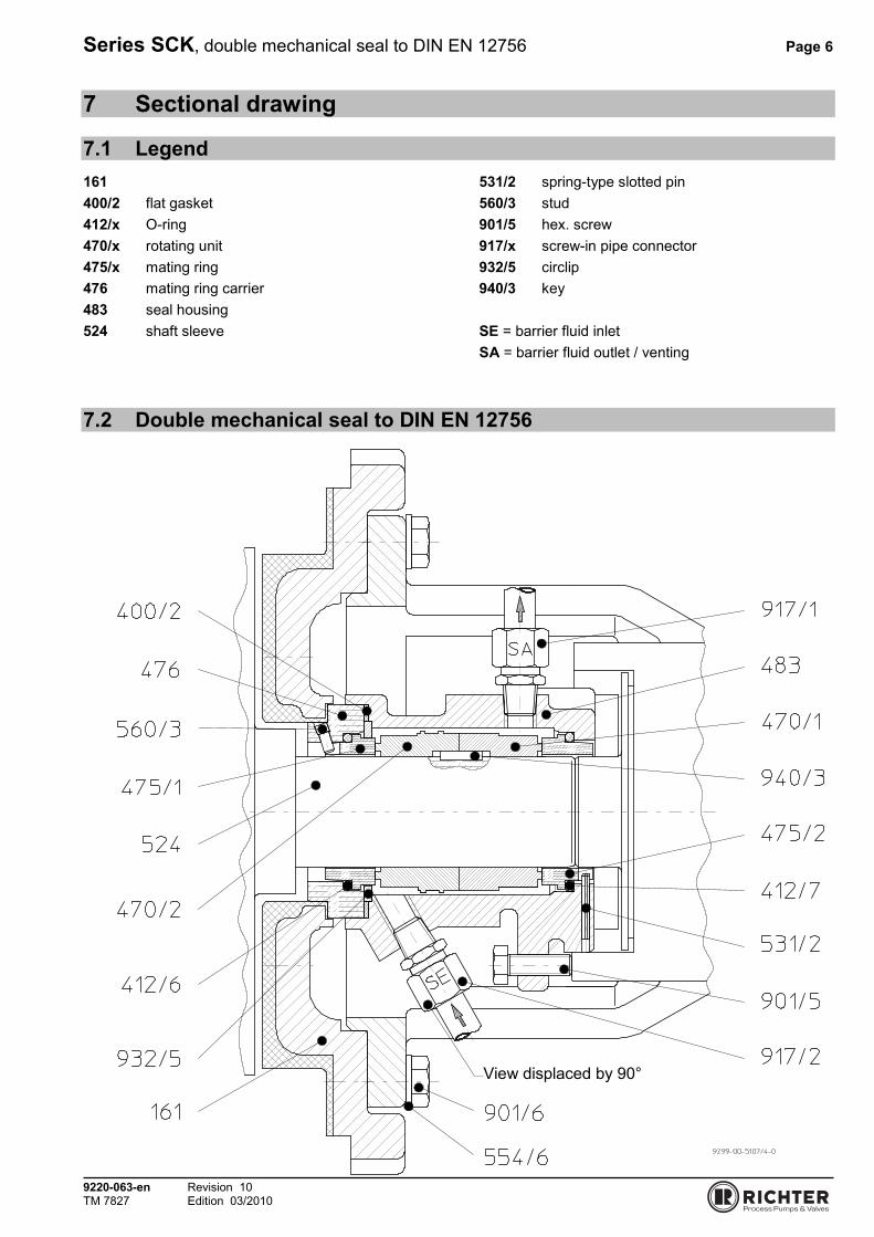
7.1 Legend 161 400/2 flat gasket 412/x O-ring 470/x rotating unit 475/x mating ring 476 mating ring carrier 483 seal housing 524 shaft sleeve
531/2 spring-type slotted pin 560/3 stud 901/5 hex. screw 917/x screw-in pipe connector 932/5 circlip 940/3 key SE = barrier fluid inlet SA = barrier fluid outlet / venting
7.2 Double mechanical seal to DIN EN 12756
View displaced by 90°