Embed Size (px)
Citation preview

Mechanical Services Standard Design, Engineering, Planning & Sustainability
University Infrastructure
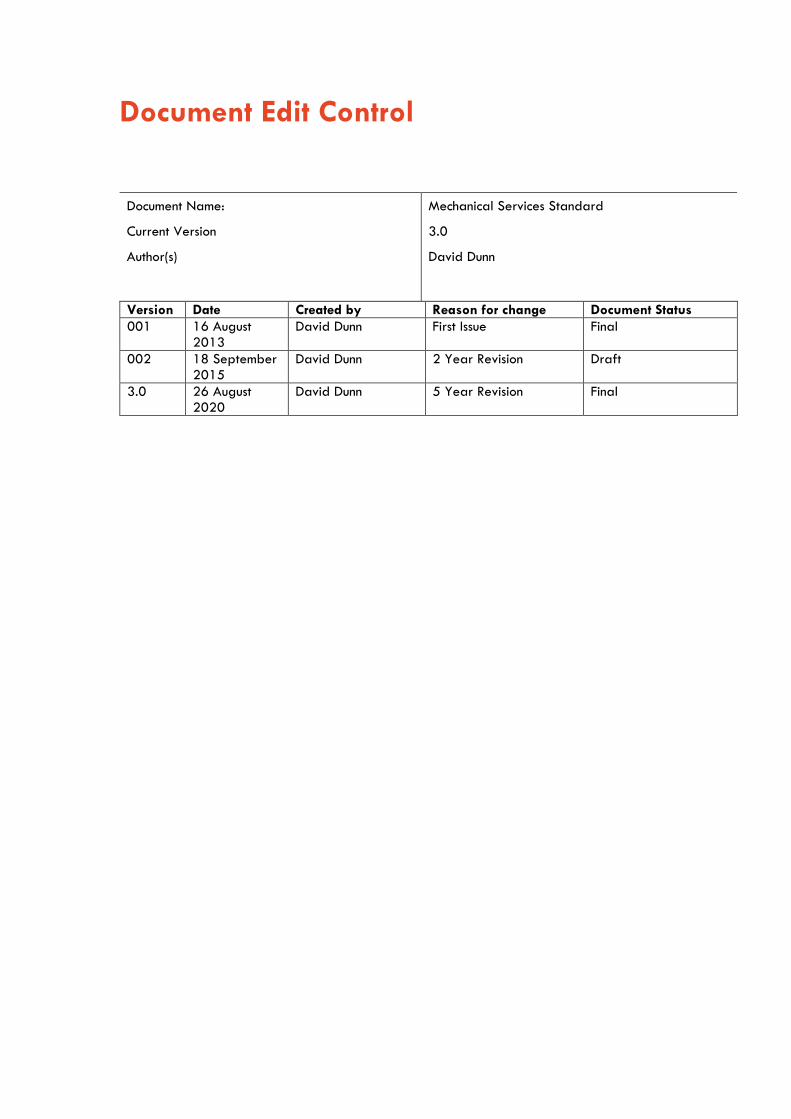
Document Edit Control
Version Date Created by Reason for change Document Status 001 16 August
2013 David Dunn First Issue Final
002 18 September 2015
David Dunn 2 Year Revision Draft
3.0 26 August 2020
David Dunn 5 Year Revision Final
Document Name: Mechanical Services Standard
Current Version 3.0
Author(s) David Dunn

Mechanical Services 1
Contents 1 Purpose .................................................................................................................................................. 7 2 Scope ...................................................................................................................................................... 7 3 Glossary of Terms ................................................................................................................................ 8 4 Roles and Responsibilities ................................................................................................................... 9 5 Construction Requirements .................................................................................................................. 9
5.1 New Buildings .................................................................................................................................. 9 5.2 Refurbishments ............................................................................................................................. 10 5.3 Reuse of existing equipment ..................................................................................................... 10
6 Technical Requirements .................................................................................................................... 10 6.1 Introduction ................................................................................................................................... 10 6.2 Design and Documentation ........................................................................................................ 10
6.2.1 Design Conditions ............................................................................................................ 10 6.2.2 Calculations ....................................................................................................................... 12 6.2.3 Equipment, System Selection and Sizing ..................................................................... 13 6.2.4 Minimum Energy, Efficiency and Heat Recovery Requirements .............................. 13 6.2.5 System Types .................................................................................................................... 14 6.2.6 Future Allowances ............................................................................................................ 14 6.2.7 Construction Indoor Air Quality Management ........................................................... 15 6.2.8 Other Design Requirements ........................................................................................... 15
6.3 Air Cooled Chillers ...................................................................................................................... 16 6.3.1 Application ........................................................................................................................ 16 6.3.2 Acceptable Manufacturers............................................................................................. 16 6.3.3 General Requirements .................................................................................................... 16 6.3.4 Corrosion protection ........................................................................................................ 17 6.3.5 Condenser Coils ............................................................................................................... 17 6.3.6 Condenser Fans ................................................................................................................ 17 6.3.7 Controls .............................................................................................................................. 17
6.4 Water-Cooled Chillers ............................................................................................................... 18 6.4.1 Acceptable Manufacturers............................................................................................. 18 6.4.2 General Requirements .................................................................................................... 18 6.4.3 Corrosion protection ........................................................................................................ 19 6.4.4 Water Boxes .................................................................................................................... 19 6.4.5 Controls .............................................................................................................................. 19
6.5 Heat Rejection Methods ............................................................................................................. 20 6.6 Cooling Towers ............................................................................................................................ 20
6.6.1 Acceptable Manufacturers............................................................................................. 20 6.6.2 General ............................................................................................................................. 20

Mechanical Services 2
6.6.3 Construction ....................................................................................................................... 21 6.6.4 Fans .................................................................................................................................... 21 6.6.5 Water Distribution ........................................................................................................... 21 6.6.6 Capacity ............................................................................................................................ 21 6.6.7 Cooling Tower Registration ........................................................................................... 21
6.7 Heating Hot Water Generators and Boilers ......................................................................... 21 6.7.1 General ............................................................................................................................. 21 6.7.2 Manufacturers .................................................................................................................. 22 6.7.3 Condensing Boilers .......................................................................................................... 22
6.8 Pumps ............................................................................................................................................. 22 6.8.1 Manufacturers .................................................................................................................. 22
6.9 Variable Speed Drives (VSD) ................................................................................................... 23 6.9.1 Model ................................................................................................................................. 23 6.9.2 Requirements .................................................................................................................... 23 6.9.3 VSD, EMC and THD Compliance .................................................................................. 24 6.9.4 VSD and Motor Protection Features ............................................................................ 24 6.9.5 Control Pad ....................................................................................................................... 24 6.9.6 Protection ........................................................................................................................... 24 6.9.7 Wiring ................................................................................................................................ 25 6.9.8 Software, Programming, Passwords and Operation and Maintenance ............... 25 6.9.9 High Level Interface and Control ................................................................................. 25 6.9.10 VSD Output Shielded Cabling ...................................................................................... 25 6.9.11 VSD Environment Protection ........................................................................................... 25
6.10 Fans ................................................................................................................................................ 25 6.10.1 General ............................................................................................................................. 25 6.10.2 Ventilation Fans ................................................................................................................ 25 6.10.3 Belt Driven Fans ............................................................................................................... 26 6.10.4 High temperature exhaust fans .................................................................................... 26 6.10.5 Kitchen exhaust fans ........................................................................................................ 26
6.11 Fire Dampers ................................................................................................................................ 26 6.12 Plant Rooms .................................................................................................................................. 27 6.13 Return, Relief and Spill air ........................................................................................................ 27 6.14 Air Handling Units (AHUs) .......................................................................................................... 27
6.14.1 General ............................................................................................................................. 27 6.14.2 Construction ....................................................................................................................... 28 6.14.3 Heat Recovery .................................................................................................................. 28 6.14.4 Spray Coils ....................................................................................................................... 28 6.14.5 Cooling Coils ..................................................................................................................... 28 6.14.6 Drip Trays.......................................................................................................................... 28 6.14.7 Heating coils ..................................................................................................................... 28 6.14.8 Filters .................................................................................................................................. 28

Mechanical Services 3
6.14.9 Mixing Box ........................................................................................................................ 28 6.14.10 Face Bypass Dampers .................................................................................................... 29 6.14.11 Location .............................................................................................................................. 29 6.14.12 Humidification / Dehumidification ................................................................................ 29
6.15 Humidifiers .................................................................................................................................... 29 6.15.1 General ............................................................................................................................. 29 6.15.2 Steam humidifiers ............................................................................................................ 29
6.16 Dehumidifiers ................................................................................................................................ 29 6.16.1 General ............................................................................................................................. 29 6.16.2 Type ................................................................................................................................... 30 6.16.3 Installation ......................................................................................................................... 30 6.16.4 Operation / Control ........................................................................................................ 30
6.17 Chilled and Hot Water Fan Coil Units (FCUs) ........................................................................ 30 6.17.1 General ............................................................................................................................. 30
6.18 Chilled Water and Hot Water Pipework ............................................................................... 31 6.18.1 Design ................................................................................................................................ 31 6.18.2 Pipe Sizing ........................................................................................................................ 31 6.18.3 Pipe material .................................................................................................................... 32 6.18.4 Copper Pipe Joints .......................................................................................................... 32 6.18.5 Cladding and Insulation ................................................................................................. 33 6.18.6 Pressure Testing ................................................................................................................ 33 6.18.7 Flashings and Penetrations ............................................................................................ 33
6.19 Chilled, Hot and Condenser Water Valves ........................................................................... 33 6.19.1 Control Valves .................................................................................................................. 34 6.19.2 Isolating Valves ................................................................................................................ 34 6.19.3 Balancing Valves ............................................................................................................. 34 6.19.4 Valves in the Ceiling Space ........................................................................................... 34 6.19.5 Valve Unions ..................................................................................................................... 34 6.19.6 Connections to Equipment ............................................................................................... 34 6.19.7 Binder Cocks ..................................................................................................................... 35 6.19.8 Vents ................................................................................................................................... 35 6.19.9 Drain/ Manual Fill Points ................................................................................................ 35 6.19.10 Thermal Meters ................................................................................................................ 35 6.19.11 Flow Meters ...................................................................................................................... 35
6.20 Condensate Drains and Safety Trays ..................................................................................... 36 6.20.1 General ............................................................................................................................. 36 6.20.2 Condensate Pumps .......................................................................................................... 36 6.20.3 Sizing and Material ........................................................................................................ 36 6.20.4 Condensate Waste Drain Insulation ............................................................................. 36 6.20.5 Condensate Traps ............................................................................................................ 36 6.20.6 Condensate Discharge .................................................................................................... 36

Mechanical Services 4
6.20.7 Safety Trays ..................................................................................................................... 36 6.21 Air Conditioning Controls ........................................................................................................... 36
6.21.1 General ............................................................................................................................. 37 6.21.2 Alarms ................................................................................................................................ 37 6.21.3 Alarm Priorities ................................................................................................................. 37 6.21.4 Fire Mode Operation...................................................................................................... 37
6.22 Motor Control Centres (MCC) and Mechanical Services Switch Boards (MSSB) ............. 38 6.22.1 Boards ................................................................................................................................ 38 6.22.2 Switchboard Fault Level and Protection Grading ..................................................... 39 6.22.3 Fire Trip Indicator and Fire Fan Control ...................................................................... 39 6.22.4 Fire Rating Essential Services ........................................................................................ 39 6.22.5 BMS and Signal Control Cabling Segregation .......................................................... 39 6.22.6 Cabling Identification ..................................................................................................... 40 6.22.7 Board Accessories ............................................................................................................ 40 6.22.8 Aggregate Harmonic Distortion Performance at the MCC Input Supply ............. 40 6.22.9 Provision for Active Harmonic Filter at the MCC ....................................................... 40
6.23 Water-Cooled Package Units (PAC) ....................................................................................... 41 6.23.1 General ............................................................................................................................. 41 6.23.2 Valves ................................................................................................................................ 41 6.23.3 Acoustic Considerations .................................................................................................. 41
6.24 Split Systems ................................................................................................................................. 41 6.24.1 General ............................................................................................................................. 41 6.24.2 Installation ......................................................................................................................... 42
6.25 VRV and VRF Systems ................................................................................................................ 43 6.25.1 General ............................................................................................................................. 43 6.25.2 Installation ......................................................................................................................... 43
6.26 Refrigerants .................................................................................................................................. 44 6.26.1 Refrigerant Type ............................................................................................................. 44 6.26.2 Refrigerant Recovery ...................................................................................................... 44
6.27 Refrigerant Pipe Work .............................................................................................................. 44 6.27.1 Flashing and Penetrations .............................................................................................. 44 6.27.2 External Trunking ............................................................................................................. 44 6.27.3 Internal pipework ............................................................................................................ 45 6.27.4 Pipe Joints ......................................................................................................................... 45 6.27.5 Pipe Supports ................................................................................................................... 45 6.27.6 Thermal Insulation ............................................................................................................ 45 6.27.7 Pressure testing ................................................................................................................ 45 6.27.8 Vacuum .............................................................................................................................. 45
6.28 Ductwork ........................................................................................................................................ 45 6.28.1 General ............................................................................................................................. 45 6.28.2 Insulation ............................................................................................................................ 46

Mechanical Services 5
6.28.3 Ductwork supports ........................................................................................................... 46 6.29 Air Grilles and Diffusers ............................................................................................................. 47
6.29.1 General ............................................................................................................................. 47 6.29.2 Exhaust Grilles .................................................................................................................. 47 6.29.3 Plenum Boxes .................................................................................................................... 47 6.29.4 Door Grilles ...................................................................................................................... 47 6.29.5 Undercutting of doors ..................................................................................................... 47
6.30 Filters .............................................................................................................................................. 47 6.31 Vibration and Noise .................................................................................................................... 47
6.31.1 General ............................................................................................................................. 47 6.31.2 Equipment .......................................................................................................................... 48 6.31.3 Piping ................................................................................................................................. 48 6.31.4 Ductwork ............................................................................................................................ 48 6.31.5 Flexible Connections for Pipework ............................................................................... 48 6.31.6 Flexible Connections for Ductwork ............................................................................... 48 6.31.7 Equipment Inertia Bases.................................................................................................. 48 6.31.8 Building Noise ................................................................................................................... 49
6.32 Fume Cabinets .............................................................................................................................. 49 6.32.1 General Requirements .................................................................................................... 49 6.32.2 Ducted Fume Cabinets .................................................................................................... 49 6.32.3 Wet Decks and Scrubbers ............................................................................................. 49 6.32.4 Manifolded fume cabinet exhaust ............................................................................... 50 6.32.5 Ductless or Recirculating Fume cabinets and Laminar flow hoods ......................... 50
6.33 Compressed Air ........................................................................................................................... 50 6.33.1 Air Compressor ................................................................................................................. 50
6.34 Painting, Labelling and Colour Schemes ................................................................................. 50 6.34.1 General ............................................................................................................................. 50 6.34.2 Painting Application ........................................................................................................ 51 6.34.3 Plant Room Floors ............................................................................................................ 51 6.34.4 Ductwork subject to Wet or Damp Environment ........................................................ 51 6.34.5 Equipment Colour Schedule ........................................................................................... 51 6.34.6 Equipment Labelling ........................................................................................................ 52 6.34.7 Naming Convention for Traffolyte labels ................................................................... 52
6.35 Service Access and Safety Requirements ............................................................................... 53 6.35.1 General ............................................................................................................................. 53

Mechanical Services 6
6.36 Redundant Equipment ................................................................................................................. 54 6.37 Product Support and Experience Requirements .................................................................... 54
7 Commissioning .................................................................................................................................... 54 8 Safety in Design ................................................................................................................................ 54 9 Documentation and Records ............................................................................................................ 55
9.1 Design Documentation ................................................................................................................ 55 9.2 Completion Documents ................................................................................................................ 55
10 Assets and Warranties ..................................................................................................................... 56 11 Defects and Liability Period ........................................................................................................... 56
11.1 Maintenance and Testing ........................................................................................................... 57 12 Operations & Maintenance Manuals ............................................................................................ 57 13 Authorisation of Variations .............................................................................................................. 58 14 Quality Control .................................................................................................................................. 58
14.1 Design Standard Compliance ................................................................................................... 58 14.2 Design Standard Certification .................................................................................................. 58 14.3 Construction Compliance ............................................................................................................ 59 14.4 Acceptance ................................................................................................................................... 59
15 Document Amendment History ........................................................................................................ 59

Mechanical Services 7
1 Purpose The UI Mechanical Services Standard sets out the University of Sydney's minimum requirements for the design, construction and maintenance of mechanical systems. It ensures new and refurbished systems are energy efficient, fit-for-purpose, made from durable good-quality materials, contain no or minimal environmentally harmful substances, and are cost efficient to operate and maintain. Applicable requirements documented in Workplace Health and Safety legislation, Disability Discrimination legislation, State Environmental Planning legislation, Commonwealth and State legislation, National Construction Codes (NCC), the Building Code of Australia (BCA) and Australian and New Zealand Standards (AS/NZS) are the minimum and mandatory compliance requirements. Where any ambiguity exists between this standard and the aforementioned mandatory requirements then:
The highest performance requirements must apply Applicable requirements must follow this order of precedence:
1. Workplace Health and Safety legislation. 2. Safety in Design Legislation. 3. Disability Discrimination legislation. 4. State Environmental Planning and Assessment legislation. 5. All other Commonwealth and State legislation. 6. NCC, BCA and PCA. 7. AS/NZS. 8. This standard and other University of Sydney standards.
2 Scope This standard describes minimum requirements for design, purchase, construction, and operation and maintenance of fire services plant, equipment and infrastructure for buildings and spaces owned, operated, maintained and/or managed by the University of Sydney. It applies to:
New building construction. Refurbishment spaces within existing buildings Facilities maintenance services.
The standards apply to all planners, project managers, consultants, contractors, sub-contractors, tenants, managing agents and University staff involved in the design, construction and maintenance of existing, new and proposed University buildings and facilities. The Standard provides:
A reference document to enable consistency with the design and engineering objectives Details of the minimum performance requirements for planning, architectural design and maintenance.
Support of the University vision for the built environment and best practice.
The Standard addresses key objectives: Quality design which responds, enhances and complements the environment Appreciation of the heritage context and cultural history of the campuses Value for money in all aspects of the project The design of low maintenance buildings and environments Longevity of construction approach to design Standardization of key flashing and ancillary details Flexible design, to future proof building usage for expansion or adaption to new uses

Mechanical Services 8
Safety in design All Mechanical systems products and services provided or specified by designers, consultants, staff and contractors must conform to this standard. Where specific applications are not explicitly covered, or ambiguity exists, the intent of the design standard must be satisfied. In such cases a return design brief must be provided for review and approval by the issuer of this standard or their appointed delegate who must have relevant technical competence in the subject matter. Additional more stringent requirements may apply on a project-specific basis dependent upon risk management and insurance requirements.
3 Glossary of Terms AHU Air Handling Unit
AS/ NZS Australian Standards/ New Zealand Standards
AUMS Advanced Utilities Monitoring System
BCA Building Code of Australia
BMCS Building Management control System
CDW Condenser Water
CFC Chlorofluorocarbon
CHW Chilled Water
COS Central Operations and Services
CT Cooling Tower
CU Condensing Unit
DDC Direct Digital Control
DLP Defects Liability Period
DX Direct Expansion
EMC Electromagnetic Compatibility
EP&AR Environmental Planning and Assessment Regulation
FC Fluorocarbon
FCU Fan Coil Unit
FIP Fire Indicator Panel
GFA Gross Floor Area
HC Hydrocarbon
HCFC Hydrochlorofluorocarbons
HEX Heat Exchanger
HFC Hydrofluorocarbons
HHW Heating Hot Water
MSDS Material safety data sheets
NATA National Association of Testing Authorities
NCC National Construction Code

Mechanical Services 9
ODP Ozone Depletion Potential
PC Practical Completion
PMV Predicted Mean Vote
PPR project principal requirements
PUG Project User Group or Project Working Group RAC Room Air Conditioner (window mounted)
SMACNA Sheet Metal and Air Conditioning Contractors' National Association
UFA Usable Floor Area
UI University Infrastructure VAV Variable Air Volume
VOC Volatile organic compound
VRF Variable Refrigerant Flow
VRV Variable Refrigerant Volume
VSD Variable Speed Drive
4 Roles and Responsibilities This standard is issued by UI. It is approved and signed off by the Chief of University Infrastructure Officer. UI is responsible for maintaining the standard and keeping it up to date.
5 Construction Requirements Due to the complex nature of the University’s Infrastructure, the requirements for construction of new buildings, and the refurbishment of existing buildings differ and must be assessed on a case by case basis. Careful consideration must be taken in relation to connection and disconnection of existing services, and the reuse of existing equipment. This section outlines the construction requirements for both new and existing buildings.
5.1 New Buildings The mechanical services provided in University buildings must be designed and installed in accordance with the minimum legislative requirements incorporating all Statutory Regulations, Australian Standards, Local Council, Work Health & Safety (WHS) and WorkCover requirements. Each building must be equipped with the appropriate mechanical services, all designed and installed in accordance with the requirements of the project PPR, NCC and Australian Standards. Additional measures may also be required to meet specific building hazards and/or the requirements of University Insurers. The consultant/contractor must take a long-term balanced view of capital costs, energy costs, maintenance costs and longevity when proposing any ’Performance Solution’, comparing the capital and operational costs of each proposed solution with the applicable DTS provisions.

Mechanical Services 10
The consultant/contractor will consult with UI, and Project User Groups, to discuss any additional mechanical services that must be included in the design, in order to suit the proposed occupancy, associated hazards, proposed equipment and environmental conditions.
5.2 Refurbishments All existing mechanical services in a building must be extended/replaced as necessary into the given project. The design for projects within existing buildings must be assessed on a case by case basis and developed in conjunction with this standard. The project scope will drive the design requirements and the extent of upgrade of the existing services. Any items not included in the scope must not be priced into the overall project to achieve the following aim; To reduce the need to value engineer any services. It is the responsibility of the consultant/ contractor to obtain the gate paper from the Project Manager to understand the scope of works in relation to the space and fit out requirements. New projects within existing buildings must assess what the expectation of the refurbishment will be. This will enable the right outcome for the given project to meet the approved budget. All project associated redundant pipework, equipment, fixings and wiring, including inaccessible ceiling spaces, must be removed as part of the project works. Make good exposed surfaces before commencing the installation of new services. This includes the removal of redundant underground services unless otherwise approved by the project superintendent.
5.3 Reuse of existing equipment Where existing equipment is utilised as part of a project it is the responsibility of the contractor to confirm its performance\condition and provide a written report to the University. All filters are to be changed\cleaned on project related equipment prior to PC. All project associated grills and outlets are to be cleaned prior to PC.
6 Technical Requirements 6.1 Introduction The Mechanical system of a University building will include surrounding structures and annexe buildings. In some cases, components of the Mechanical system will be installed or are to be installed in other buildings. In these cases, the word building in this document must be interpreted as inclusive of these structures, annexes and components.
6.2 Design and Documentation Ensure that plant and equipment are designed with access and visual impact taken into consideration
6.2.1 Design Conditions Load estimations are to be performed using established weather design data for specific project location (such data as AIRAH or ASHRAE). A general square meter approach must not be used.

Mechanical Services 11
The University external design conditions for Camperdown/Darlington/Mallett Campuses are Summer 35.0°C DB/ 24°C WB, Winter 6°C DB.
For all other campuses, refer to the design consultants’ specified design conditions For general office and teaching spaces, the indoor design conditions must be for a minimum condition of 20˚C in peak winter and a maximum condition of 26˚C in peak summer conditions, humidity is not controlled but the summer design condition must be 55% relative humidity.
For special spaces such as labs, animal houses and research facilities refer to specific PPR for internal space design conditions note that spaces are to be designed to maintain internal conditions during peak summer and winter conditions
Air conditioning of general public spaces used as student and staff congregation and informal meeting areas are to be considered on a case by case basis. Where temperature control is deemed necessary, the design conditions required are:
minimum of 20˚C in winter; and maximum condition of 27˚C in Summer Acoustics of a space must comply with AS/NZS 2107. Designers and contractors must ensure
they take care to attenuate all equipment and that equipment is suitably located to reduce noise transfer to occupied spaces
The following requirement must be met, in relation to thermal comfort:
For naturally ventilated and mechanically assisted naturally ventilated spaces, if the useable floor area falls within the acceptable Limits of ASHRAE Standard 55-2004 they are required to achieve to this standard during standard operating hours of occupancy for 98% of the year for internal temperatures within 80% of Acceptability Limit
For mechanically air-conditioned spaces, the Usable Floor Area (UFA) must fall within the Predicted Mean Vote (PMV) levels, calculated in accordance with ISO7730, for standard operating hours of occupancy for 98% of the year using standard clothing and metabolic rate values for PMV levels between -0.5 and +0.5, inclusive for 95% of the UFA
For mixed-mode buildings, the above mechanical and natural ventilation thermal comfort criteria must be met for the relevant UFA where the systems are provided
Comply with the following Air Change Rates per hour as per Table 1 below.
Table 1: Thermal Comfort ACH rates
All spaces in general min 4
Assembly halls 4 - 6
Auditoriums 8 - 15
Boiler rooms 15 - 20
Cafeterias 12 - 15
Classrooms 6 - 20
Computer Rooms 15 - 20
Court Houses 4 - 10
Engine rooms 4 - 6
Hospital rooms 4 - 6
Kitchens 15 - 60
Laundries 10 - 15
Libraries, public 4

Mechanical Services 12
Lunchrooms 12 -15
Luncheonettes 12 -15
Machine shops 6 - 12
Malls 6 - 10
Medical Centres 8 - 12
Medical Clinics 8 - 12
Medical Offices 8 - 12
Museums 12 -15
Offices, private 4
Paint shops 10 - 15
Photo dark rooms 10 - 15
Pig houses 6 - 10
Poultry houses 6 - 10
Precision Manufacturing 10 - 50
Pump rooms 5
Residences 1 - 2
Restaurants 8 - 12
School Classrooms 4 - 12
Substation, electric 5 - 10
Swimming pools 20 - 30
Theatre’s 8 - 15
Transformer rooms 10 - 30
Turbine rooms, electric 5 - 10
Warehouses 2
Waiting rooms, public 4
Warehouses 6 - 30
Wood-working shops 8
6.2.2 Calculations Use of computer-based load modelling/simulation/estimation programs that account for building elements thermal storage and diversification of peak loads for each zone and air-handling system must be performed. This must be part of the design advice to all services and inform the building performance. Specifically, the University requires large areas such as congregation spaces, glue areas, foyers and linkage spaces not typically fully conditioned to be modelled to ensure thermal conditions are maintained within acceptable limits.

Mechanical Services 13
6.2.3 Equipment, System Selection and Sizing The University expects consultants and designers to select products of proven and reliable quality, with reputable support and after sales service. The University expects consultants and designers to follow good industry practice. Additionally, the following are some particular points of note:
Chillers and chilled water plant must be sized and configured to handle peak load, part load and minimum load conditions in a stable and efficient manner. This may include the choice of particular chiller types, capacity, buffer storage or dedicated low load chillers.
Chilled, hot, condenser water and air systems must be designed as variable volume/flow systems to allow for turn down in capacity and energy usage reduction
Pumps and fans must be selected in their stable range and high efficiency points of the pump and fan curves, for variable flow applications, ensure that the entire flow range is stable
In applying diversity factor, consider if the building is used in summer months or not and apply accordingly. For buildings which only operate during university semesters, peak loads may not occur in summer as the building may be closed. Consider either applying diversity in the calculations, or analyse the loads on a whole year and select leaks at other times or configure the plant to allow for load steps to match
For critical environments such as animal houses, special laboratories, clean rooms, museums or the like, stable operation of chillers and/or other refrigeration systems are crucial. Thus, chillers of the appropriate capacity and type with suitable part load and low load characteristics are required
Critical environments must have duty standby setup installed on its equipment to ensure stable operation 24/7
Products which are of closed systems and proprietary in nature, thus locking the University into exclusive dependence of one manufacturer must be avoided and only used if there are no other options and approval is provided as per section 10 of the Design and Dispensation Standard
The system designer during the design phase is to provide a pipe-work schematic highlighting the system flow rates, velocities and friction rates.
Where there are multiple chillers and boilers, a minimum of two bypass lines and valves must be installed. One sized for high loads and the other for low loads.
All equipment must be selected to ensure it complies with the UI BMCS standard and can provide the required inputs and outputs that are called up in the UI BMCS Standard
6.2.4 Minimum Energy, Efficiency and Heat Recovery Requirements Ducted air conditioning systems with higher than 1000L/s outside air must incorporate air-to-air heat exchangers for heat recovery or automatic outside air modulation in proportion to occupancy numbers. Bypass dampers must be considered for incorporation on all heat exchangers to ensure reduction in energy usage when heat exchanger is not being utilised.
For ducted air conditioning systems or single rooms that have a higher than 35 kW cooling load, an outside air economy cycle must be incorporated
All motors for pumps and fans that have or may have the ability to change speed must be provided with variable speed drives (VSD)
All compressors must be variable speed and vary speed with change in loads CO2 sensors must be installed on systems with a capability to modulate outside air volume.
Each return duct (at a minimum) sensor must be installed and must maintain a CO2 concentration of below 800ppm
Thermal storage must be considered to provide building redundancy, peak load reduction and low load operation assistance
Automatic shutdown of plant when spaces are unoccupied must be provided as a minimum, where spaces form part of a larger air system then positive shutoff of the spaces supply air must be provided when the space is unoccupied

Mechanical Services 14
Central toilet exhaust systems must have VSD drive installed and toilet occupancy sensors connected to drop exhaust rate when toilets are not occupied
General toilets must have occupancy sensor linked to the toilet exhaust system to shut the system down when there has been no movement in the space in the afterhours period. Toilets are to operate off time clock during office hours and motion sensor afterhours.
An energy model and report using BCA Section J energy modelling guidelines and the small plug loads template must be completed as per UOS Sustainability Framework. The designer/consultant is to ensure the predicted energy consumption for each space type within the building and predicted total value for the Building’s annual energy use perform at least 20% better than the reference building when the proposed building is modelled with the proposed services.
All HVAC equipment are to have the highest energy rating available under the Australian Government’s Energy Rating scheme for each standard capacity range of the appliance. Where multiple products are available in the market with the highest energy rating, preference must be given to locally manufactured products.
6.2.5 System Types The following are application guidance for various system types:
Mixed-mode ventilation for offices, meeting rooms and teaching and learning spaces where operable windows are available. A reed switch must be provided to automatically switch off all fan coil units when the operable windows are open to avoid energy wastage.
Meeting rooms must have independent FCUs installed or VAVs with the ability to completely shut off air flow when not occupied.
All VAV systems with variable speed air handling units have proved to be reliable and appropriate for most applications
Use of corridors/foyers as relief paths if possible and appropriate to reduce supply air to these areas
Passive chilled beams must not be used. Passive chilled beam systems have been problematic due to the changing nature of university buildings. Active chilled beams are acceptable.
The University does not accept ceiling cassette units as an appropriate system type for installation in office spaces with ceiling heights lower than 2.7 metres
Underfloor displacement systems have proved to be acceptable in large tiered and arced teaching spaces. Specific care must be taken to ensure disabled/wheelchair allocated spaces are conditioned design as well must ensure lecturer receives targeted conditioning. Lecture theatres must be provided with specific supply to ensure adequate cooling/heating is provided. The university does not accept secondary air as a means of conditioning the lecture theatre.
Within all spaces that have projector screens, care must be taken to ensure supply and return air do not cause movement of the screens.
Variable speed water-cooled chillers and multi-stage air cooled chillers must be used Use of split systems must only be permissible for very small additions to existing buildings.
When these are used, ensure that they are sited in appropriate locations and any pipework reticulation is not unsightly, with appropriate cladding and run in a neat and tidy manner. All precautions must be taken to conceal the outdoor unit such as putting units on accessible roofs, existing external plant spaces or behind vegetation.
Use of RAC window units are not accepted Use of Portable Units are not accepted
6.2.6 Future Allowances The provision of spare capacities for future must be considered for all projects. In making such considerations, careful analysis of spare capacity against the application of diversity and the balance thereof must be considered. The practicality of equipment sizing and selection against

Mechanical Services 15
its product range can be used appropriately if and when equipment is rated for given capacities which may provide spare capacity without upsizing. Where central risers are installed, they must be sized to accommodate the full building’s requirements and future provisions All infrastructure and plant rooms must be future proofed to allow for readily accessible connection points to future precinct-based energy and water distribution systems (e.g. hot/chilled water loops), ensuring that precinct buildings can transition across to centralised services as per UOS Sustainability Framework.
6.2.7 Construction Indoor Air Quality Management The consultant and or designer must develop an Indoor Air Quality Management Plan (IAQMP) which incorporates the following:
HVAC protection from both dust and odours Source control of any materials that contain Volatile Organic Compounds (VOCs). The construction team must be required to recover, isolate and ventilate containers housing toxic materials
Pathway interruption, clean or occupied areas are to be isolated from areas of work Housekeeping, cleaning activities are to be regularly undertaken to control contaminants Maintenance team should protect all porous materials from exposure to moisture. Vacuum cleaners with high efficiency particulate filters should be used
Scheduling - the IAQMP should outline the schedule of activities for cleaning prior to occupancy including flush-out activities
Ductwork cleaning - all new and existing ductwork serving the building must be cleaned in accordance with recognised standards or construction management processes have been set-up and adhered to that ensure all new ductwork, or ductwork that has been recently cleaned, remains free of moisture and debris until occupation
6.2.8 Other Design Requirements All adhesive and sealant products used internally must have low Total Volatile Organic Compound levels (TVOCs)
Where dedicated fume cupboard makeup air systems are utilised, makeup air must be tempered and to only be activated when the fume cupboard system is operational
The water control loop volume must be sized for at least the minimum chiller/boiler requirements
Plant rooms must be naturally ventilated and where not, capable mechanical ventilation must be provided to assist temperature control
All roof installations and penetrations must comply with the UI Roofing and Guttering Standard along with the UI Essential Fire Safety Measures Standard. This particularly applies to fire dampers and the type of inspection hatch required.
The contractor must provide input to the Building Users’ Guide (BUG) for all mechanical systems as per UOS Sustainability Framework. Information must be provided about the building’s use, functional and environmental aspects, and special features of the building and systems
A minimum distance of 600mm must be provided between the roof surface and the lowest point of any equipment installed on or below a roof platform
In conditioned spaces, outside air must be supplied into a mixing plenum and not directly supplied into a space without conditioning
For critical environments such as animal houses, special laboratories, clean rooms, constant temperature environments, museums or the like, the design must include redundancy built into the design. This may include duty/standby arrangements or selection of systems that are of a robust nature

Mechanical Services 16
For photocopy and print rooms, allow for dedicated exhaust system or connection to base building exhaust system
Sensors must be suitably located to ensure accurate sensing of the space temperature. Sensors must not be installed on locations that will provide a false reading (i.e. in direct sunlight, under or near screens and other equipment, etc.)
Critical control environments must be provided with certified sensors Where systems are installed in heritage buildings, specific design/approval from the University on the system solution and location of equipment must be obtained from UI Engineering and UI Heritage advisor
Floor Differential Pressure sensors must be installed on all systems that service multiple floors including supply air and chilled\heating\condenser water.
Exhaust systems must not run ducts under a positive pressure within a building all exhaust ducts must be under a negative pressure. This requirement does not apply to general space exhaust such as offices, lecture theatres, corridors and transient spaces
Gas/cryogenic liquid storage rooms or spaces containing these must be fitted with an exhaust system designed to exhaust the specific gases stored within the space, such as low-level duct work for heavier than air gasses or spark-proof fans and equipment for flammable gases. Systems must be fitted with a boost feature to allow the capability of purging the space so that all oxygen levels must be maintained at a safe level. Purge feature must be initiated from either a manual push switch or when a low oxygen level alarm or high gas level alarm is activated. When safe levels have been achieved, then system is to reduce exhaust rate to design conditions. In addition: i. Typical emergency purge rate is doubled to double the design exhaust rate while in
purge mode ii. Low flow ventilation alarm must be included in system to activate warning alarm
6.3 Air Cooled Chillers
6.3.1 Application Air cooled chillers must be used up to total system cooling capacities of 500 kW. For applications where each chiller is rated at higher capacities, preference is given to water cooled arrangements. For total system capacities above 750 kW, water cooled systems must be used.
6.3.2 Acceptable Manufacturers The following equipment are deemed to comply with this standard:
Trane Carrier Powerpax/ Smardt
Other alternative equivalent equipment maybe provided subject to approval via the variation procedure listed in section 9 of this standard. For process chilled water systems, Aquacool and Stulz are acceptable suppliers. Other alternative equipment maybe provided subject to approval via the variation procedure listed in section 9 of this standard.
6.3.3 General Requirements Chillers must be variable speed above 500kW, fixed speed machines will not be accepted above this capacity.
The chiller controls must be configurable for manual or automatic start up and shutdown. In automatic operation mode, the controls must be capable of automatically starting and stopping the chiller. Controls must be capable of automatically resetting and resuming normal operation after power outage.

Mechanical Services 17
Chillers must be rated for continuous operation of up to 46°C ambient without tripping. The selected capacity must be rated at the design outdoor condition.
They must be equipped with soft starters and electronic expansion valves. Refrigerant isolation valves must be fitted for easy recovery of refrigerant. Isolation valves
must be fitted to refrigerant dryer and oil filters. Electronic expansion device must be used, permitting operation at a lower condensing
pressure and improved utilisation of the evaporator heat exchange surface. Additional acoustic enclosures may be required, subject to noise control requirements specific to the project and based on the advice of the project acoustic consultant.
Chillers must be able to operate at a minimum of 20% of rated capacity in a stable and continuous manner.
Hot Gas Bypass is not accepted All cold surfaces must be insulated that condensation can form on During construction, the chiller must be fully covered from dust and moisture. When installed in a plant room refrigerant monitoring is required and connected to the
BMCS. A Visual indicator is to be provided in plant room and outside with labelling.
6.3.4 Corrosion protection All surfaces of chiller to come pre-treated and factory painted. Chiller and pipe work must be isolated via rubber flexible coupling.
6.3.5 Condenser Coils Condenser coil protection must be of e-coating for micro-channel coils and Blygold for standard tube and fin condensers.
6.3.6 Condenser Fans Condenser fans must be multistage, systems installed to run under low ambient and low load conditions, condensers must have variable speed fans to maintain stable refrigeration system operation.
6.3.7 Controls Manufacturer must ensure that they comply with the University's control strategy for chilled water system, noncompliance with University's control strategy will result in chiller being rejected.
All passwords, software and hardware must be provided to the University for service of chillers.
Chiller control systems must be BACnet High Level Interface compatible. Chiller units must incorporate devices to limit the number of starts to a maximum of four (4) per hour. The design of the system and the sizing of capacity to match building load characteristics is an important factor and constants and designers must ensure that this has been considered in their design.
The chiller controls must be configurable for manual or automatic start up and shutdown. In automatic operation mode, the controls must be capable of automatically starting and stopping the chiller. Controls must be capable of resetting and resuming normal operation after power outage or flow failure. Repeated flow failure alarms within a set time period must lock the chiller out and manual reset must be performed.
Hard wired control inputs/outputs points to be available include:
Contact for remote alarm for each refrigerant circuit Automatic chilled water reset hard wired signal to chiller from external source and HLI through BMS
Outputs for driving chilled water pumps Cooling call External safety device loop (such as pressure and flow switches)

Mechanical Services 18
The following points must be available from the local controller:
Entering/Leaving chilled water temperature Ambient temperature Condenser fan operation Refrigerant pressures and temperatures Oil temperature and Pressure Automatic chilled liquid reset timer programmed locally at chiller controller Soft loading control by temperature or load ramping Power (demand) limiter Manual speed control (Variable speed Chiller) Chiller operating status message Cooling call mode i.e.: local or remote Power-on/off Pre-start diagnostic check Compressor motor amps Alert (pre-alarm) Alarm and description of fault I/O test function Safety shutdown messages Elapsed time (hours of operation) Monitor/number compressor starts and run hours Chiller input kW Demand kW
6.4 Water-Cooled Chillers
6.4.1 Acceptable Manufacturers The following equipment is deemed to comply with this standard:
Trane Carrier; and Powerpax/Smardt
Other alternative equivalent equipment maybe provided subject to approval via the variation procedure listed in Section 9 of this standard.
6.4.2 General Requirements Chillers must be variable speed, fixed speed machines will not be accepted. The chiller controls must be configurable for manual or automatic start up and shutdown. In automatic operation mode, the controls must be capable of automatically starting and stopping the chiller.
Controls must be capable of automatically resetting and resuming normal operation after power outage or flow failure. Repeated flow failure alarms within a set time period must lock the chiller out and manual reset must be performed.
Chillers must be rated for continuous operation of up to 46°C ambient without tripping. The selected capacity must be rated at the design outdoor condition.
They must be equipped with soft starters and electronic expansion valves. Refrigerant isolation valves must be fitted for easy recovery of refrigerant. Isolation valves
must be fitted to refrigerant dryer and oil filters. Electronic expansion Device must be used permitting operation at a lower condensing pressure and improved utilisation of the evaporator heat exchange surface.
Subject to noise control requirements specific to the project and based on the advice of the project acoustic consultant, additional acoustic enclosures may be required.
Chillers must be able to operate at a minimum of 15% of rated capacity in a stable and continuous manner.

Mechanical Services 19
Hot Gas Bypass is not accepted All cold surfaces must be insulated that condensation can form on When installed in a plant room refrigerant monitoring is required and Connected to the
BMCS. A Visual indicator is to be provided in the plant room and outside with labelling. During construction chiller must be fully covered from dust and moisture. Chiller must be pre-factory tested with certification of test.
6.4.3 Corrosion protection All surfaces of chiller to come pre-treated and painted, water boxes to be ceramic coated before commissioning of chiller with a five-year warranty on ceramic coating performance.
Tube sheets are to be stainless steel or ceramic coated. Contractor is to remove water boxes and must provide University notice to allow inspection
of the tube sheets and the water boxes during DLP. Chiller and pipe work to be isolated via rubber flexible coupling to the chiller
6.4.4 Water Boxes Water boxes must have vents, drains, and be of marine grade A materials. Allow for tube cleaning space in plant rooms as per manufacturers’ recommendation. Service space must be shown on the drawings
Water boxes must be ceramic coated or be made of stainless steel. A thermistor type temperature sensor with quick connects must be factory installed in each
water box.
6.4.5 Controls Manufacturer must ensure that they comply with University control strategy for chilled water system, non-compliance with University control strategy will result in chiller being rejected.
Chiller must send the condenser water pump speed signal to the BMCS, the chiller must not send the signal directly to the condenser water pump drive.
All passwords, software and hardware must be provided to the University for service of chillers. Chiller control systems must be BACnet High Level Interface compatible. Chiller unit must incorporate devices to limit the number of starts per hour to maximum of four (4) per hour. The design of the system and the sizing of capacity to match building load characteristics is an important factor and constants and designers must ensure that this has been considered in their design. The chiller controls must be configurable for manual or automatic start up and shutdown. In automatic operation mode, the controls must be capable of automatically starting and stopping the chiller. Controls must be capable of resetting and resuming normal operation after power outage. Hard wired control inputs/outputs points to be available
Contact for remote alarm for each refrigerant circuit Automatic chilled water reset hard wired signal to chiller from external source and HLI through BMS
Outputs for driving condenser pumps Outputs for driving chilled water pumps Cooling call External safety device loop (such as pressure and flow switches)
The following points are to be available from the local controller
Entering/Leaving chilled water temperature

Mechanical Services 20
Ambient temperature Condenser fan operation Refrigerant pressures and temperatures Oil temperature and Pressure Automatic chilled liquid reset timer programmed locally at chiller controller Soft loading control by temperature or load ramping Power (demand) limiter Manual speed control (Variable speed Chiller) Chiller operating status message Cooling call mode i.e.: local or remote Power-on/off Pre-start diagnostic check Compressor motor amps Alert (pre-alarm) Alarm and description of fault I/O test function Safety shutdown messages Elapsed time (hours of operation) Monitor/number compressor starts and run hours Chiller input kW Demand kW
6.5 Heat Rejection Methods The choice of heat rejection method for water cooled chilled water systems must be assessed for each specific project.
Closed-circuit coolers offer water savings but require a larger area, more acoustic treatment and thus, greater capital costs. The indirect nature of cooling also requires greater running costs. Therefore, their application must be carefully assessed, and the advantages and disadvantages analysed in a balanced manner.
Conventional use of cooling towers requires the lowest capital and running costs but have a higher requirement of maintenance and water consumption costs associated.
Consultants and designers are expected to assess the unique nature of each project and the priorities therein to make appropriate recommendations.
For process cooling loads, closed loop systems must be utilised
6.6 Cooling Towers
6.6.1 Acceptable Manufacturers The following equipment is deemed to comply with this standard:
BAC Aquacool Marleytemcel EvapCo
Other alternative equivalent equipment maybe provided subject to approval via the variation procedure listed in section 9 of this standard.
6.6.2 General
When cooling towers are used in water cooled chilled water systems Cooling tower and installation must comply with all relevant codes, standards, acts and regulations.

Mechanical Services 21
Cooling towers must be designed and installed strictly in accordance with AS3666 and AS1055 as a minimum requirement. Care must be taken in its location with respect to intakes of air conditioning and ventilation systems, kitchen exhaust systems and similar locations which may pose a risk and provide breeding environments for legionella.
Pipe work connection to cooling tower must be a flexible connection Side-stream filtration and Automated Dosing system must be provided. The tower and its installation on site must be designed to facilitate easy fan removal and
maintenance with the installation of a platform and ladder for accessing/ removing the cooling tower fan and drift eliminators.
6.6.3 Construction Cooling towers to be of fibreglass reinforced polyester (UV resistant) or stainless-steel construction.
Sumps must be one piece and coated with a smooth gel coat finish to increase bacteria resistance of the sump.
All parts must be accessible for cleaning and service. All access panels must have seals to prevent water leakage. All steel support components must be heavy gauge hot dip galvanised steel and all welded
components after fabrication must be hot dip galvanised.
6.6.4 Fans All cooling tower fans must:
have VSD drives fitted be fully enclosed and weatherproof to IP 55 rating with Class F insulation with windings that are tropic proofed.
ensure maximum fan operation speed must not exceed 1000RPM have epoxy coated type fan motors
6.6.5 Water Distribution Header pipes must be configured to ensure even distribution over the entire fill area. UPVC or ABS Nozzles must be used.
6.6.6 Capacity Cooling towers dedicated to chilled water systems must be a minimum of 15% oversized for the designed heat rejection capacity.
6.6.7 Cooling Tower Registration New tower certification and closure of towers is part of the project’s requirements to be undertaken, all documentation and certifications to be provided to the University. Labelling of cooling with its unique ID number and certification number is to be undertaken by the contractor.
6.7 Heating Hot Water Generators and Boilers
6.7.1 General Boilers must be in installed as per the following
Installed on concrete slabs within plant rooms Interlock with the boiler pump and a supply air fan. Gas leak detection alarm to be interlocked with the operation of the boiler where required by code.
Plantroom ventilation must be provided

Mechanical Services 22
Audible gas monitoring system with alarm must be installed and connected to BMCS A gas leak alarm isolation button to be installed outside the plantroom The flues from multiple boilers may be merged into a common exhaust flue. Insulation to be
provided to minimize condensation and to prevent creating a hazard from maintenance persons
Flue drainage must lead to waste line Must have capability for temperature reset for efficiency All points monitored as per BMCS standard Isolation valves must be installed in each circuit in accessible locations to provide system
maintenance and clearly show on the schematic design. Boilers must automatically restart after gas outage and after fire trip has been reset
6.7.2 Manufacturers The following equipment is deemed to comply with this standard: Atmospheric
Raypak Simons
Forced craft sectional cast-iron
Ferroli Hoval
6.7.3 Condensing Boilers Must have minimum efficiency rating of 95%
Return water entering condensing boiler from heating circuit must be below dewpoint of flue gases (below 52°C)
For retrofits to existing systems, condensing boiler must be lead boiler For heating demands <600kW, modular boiler arrangement to be used on condensing
boilers For existing buildings, condensate must be neutralised before discharge to waste lines Flues must be made of stainless steel Flue joints must be spigot/socket type, and sockets must face upwards Horizontal flue joints must be either flanged/gasketed with high temperature silicone sealant applied where appropriate
Manufacturer supplied acid neutraliser kits to be provided with installation
6.8 Pumps
6.8.1 Manufacturers The following are general requirements for pumps:
Must be end suction pull out type. Closed-coupled types are not acceptable. Casings must be gun metal or cast iron Impellers must be bronze Shafts must be stainless steel Maximum speed must be 1450 rpm, for applications where the flow rate is below 4 L\s this
will be reviewed on a case by case basis to increase the maximum pump speed for efficiency.
All pumps must be mounted on an inertia base Motors for external applications must be IP56, totally enclosed, selected for non-overloading
Pumps above 0.75 kW must be selected with a minimum efficiency of 70%. Pumps below 0.75kW must be of minimum 50% efficiency
For chilled water applications, provide stainless steel drip tray between pump and base, and extend beyond edges and flanges

Mechanical Services 23
Allow for 20% spare capacity in pump selection Provide permanent marking of pump rotation direction Provide permanent nameplates of make, model, rating and serial number During construction pump and motor are to be fully covered from dust and moisture.
The following equipment is deemed to comply with this standard:
Grundfos Ajax Masterflow
Other alternative equivalent equipment maybe provided subject to approval via the variation procedure listed in Section 9 of this standard.
6.9 Variable Speed Drives (VSD)
6.9.1 Model The following equipment is deemed to comply with this standard:
Danfoss ABB WEG CSW10 (For situations where drive is installed inside the fume cabinet)
Other alternative equivalent equipment maybe provided subject to approval via the variation procedure listed in Section 9 of this standard.
6.9.2 Requirements VSDs must be BACnet compatible and connected to the BMCS Note that for Fume Cabinets with VSD`s installed internally i.e. in the lab space a WEG CSW10 is to be utilised, this is due to it not utilising any internal fans for cooling and a heatsink is used. The use of this drive is to increase the reliability in lab spaces where the air is contaminated and causes long term issues with drives electronics. These drives are provided with only three outputs for BMCS low level connection run signal, alarm and 0-10-volt sash position. BACnet HLI is not available for this drive.
VSD to be positioned and installed as per manufacturer’s instruction, including earthing and sheathing of VSD cabling
Servicing of the drive must not require access from the back of the VSD. The VSD must be solid state adjustable frequency drive type controlled by a
microprocessor and suitable for use on cube power absorption loads such as fans and pumps
The drive must be capable of adjusting the speed of any 415V, 50 cycle, 3 phase motor of suitable power rating over a full speed range and determine the optimum power supply to its connected motor to maintain the most efficient running characteristic of that motor. The drive must be capable of starting a motor that is freewheeling backwards.
During construction VSDs are to be fully covered from dust and moisture. The drives must be able to accept a fire signal to run at a designated speed under fire
condition where required. The variable speed drive must be interfaced to the University's BMCS DDC system and
allow full monitoring and control functions from the Front-End Terminal Where located externally and enclosures are provided, forced ventilation to the enclosure
must be provided
VSDs must include the following features: Ventilating enclosure 4-20 mA DC or 0-10VDC signal Separately adjustable ramps for soft start and soft stop Manual speed control

Mechanical Services 24
Manual reset button for all trip functions Adjustment facility for maximum and minimum speed setting Electronic overload motor protection - Faulty alarm relay -0-10VDC speed indicating signal.
6.9.3 VSD, EMC and THD Compliance Preference must be given to using VSDs using IGBT input rectifier systems if available, for the rated load, as these provide very low input harmonic distortion.
Electromagnetic Compatibility and Harmonics Incorporate filters to limit radio frequency interference and electromagnetic emission to the levels prescribed by AS/NZS CISPR 11 Group 1 Class A. External RFI filters are not acceptable.
The VSD must comply with E.M.C. (Electromagnetic Compatibility) (R.F.I. Control) document VDE0875 (EN55011).
The manufacturer must issue a Certificate of Compliance upon request. It must conform to immunity standard IEC 801 parts 2 to 5. The VSD must carry the C.E. Mark of Compliance.
Provide DC link harmonic filtering with inductors and capacitors in the DC Bus to limit the Harmonic Distortion Current into the incoming supply to no greater than permitted by AS/NZS 61000.3.12:2013 - Electromagnetic compatibility (EMC) - Limits. “Limits for harmonic currents produced by equipment connected to public low-voltage systems with input current >16 A and =75 A per phase”, or lower if required to achieve aggregate compliance with this standard for all loads at the respective mechanical switchboard.
VSDs not incorporating DC inductors may include maximum 5% AC input inductors to achieve compliance.
Comply with Harmonic emission requirements of AS 61800.3-2005 - Adjustable speed electrical power drive systems - EMC requirements and specific test methods The VSD must include a radio frequency suppression filter, within its enclosure, to ensure compliance with AS61800.3 as follows:
For powers ≤90kW the VSD - Category C1 products with 50m motor cable; For powers >90kW the VSD - Category C2 products with 50m motor cable;
6.9.4 VSD and Motor Protection Features The VSD motor must incorporate the following protection functions:
Over voltage, under voltage and mains phase loss Output earth fault, short circuit and loss of motor phase Switching on output (alternatively control interlock to VSD allowed) Flying start of motor in forward or reverse direction Electronic motor thermal protection and motor condensation protection Over current / current limit with automatic ramp control Inverter overload / over temperature / operation without motor Automatic re-start must be available on over/under voltage and current limit trip
6.9.5 Control Pad The control panel must include: a. Manual/off/auto, start, stop and reset control functions b. Output current, voltage, frequency, kW, kWh, Hours run, heat-sink temperature reference
and feedback signal indication: c. Last event fault memory and program lock.
6.9.6 Protection The drive must have ingress protection against duct and splashing water in all directions to not less than IP-54.

Mechanical Services 25
A door mounted control panel must be incorporated with alpha numeric display and keypad for programming, status and fault diagnostics indication in plain English.
6.9.7 Wiring VSDs connected to the BMCS must have status, enable, fault and start/stop signal hard wired all other parameters will be provided via the BACnet HLI.
6.9.8 Software, Programming, Passwords and Operation and Maintenance Provided with installation of VSD:
Software and required unique devices for programming VSD VSD program parameters once final commissioning is complete HLI Points list All product passwords for servicing and installation Installation diagrams Sizing information of drive Wiring requirements Application support information Trouble shooting charts
6.9.9 High Level Interface and Control BACnet HLI must make available a minimum number of points, please refer to BMCS standard for minimum required points. The control signal to the VSD must be provided via a low-level interface control signal such as a 0-10v DC signal. The low-level control signal must be adjustable via BMCS for testing and maintenance purposes.
6.9.10 VSD Output Shielded Cabling Provide shielded multicore cables specifically designed and identifiable for use with VSDs. Restrict maximum length of output cabling to 45m.
6.9.11 VSD Environment Protection VSDs must be located within plant room spaces. If an external location is impossible to avoid, then irrelevant of any manufacturers IP rating, locate exterior VSDs under an awning / shade providing protection from direct sunlight and rain.
VSDs must not be located in enclosed boards
6.10 Fans
6.10.1 General All 3 phase motors must be MEPS 2 compliant. Must be variable speed with VSD
6.10.2 Ventilation Fans The following equipment is deemed to comply with this standard:
Fantech

Mechanical Services 26
Other alternative equivalent equipment maybe provided subject to approval via the variation procedure listed in section 9 of this standard. Fans and motors must have 10% additional capacity for future refurbishment flexibility.
6.10.3 Belt Driven Fans Drive sizing:
size for ≥ 125% of motor power and capable of transmitting the full starting torque without slip
Belts: Wedge belts to AS 2784, consisting of matched sets of at least 2 belts. Mark belt size in a prominent location on the fan casing. Belt tensioning: Provide adjustment of belt drive tension by either movement of motor on slide rails or by
pivoting support. Do not use the weight of motors to provide belt tension. Restrain motors with locknuts on bolts, clamping motors in place. Provide rigid, removable belt guards on all fans where drive is accessible while motor is
running. Provide the following:
iii. Tachometer opening iv. Perforated sides on double width, double inlet fans v. Weatherproof construction, ventilated and drained where exposed to weather. vi. Material: Open mesh or perforated metallic coated sheet steel.
6.10.4 High temperature exhaust fans Provide heat slingers and guards on shafts between the inboard bearings and fan casings. Locate inboard bearings clear of fire rated insulation applied to fan casings.
6.10.5 Kitchen exhaust fans In addition to the requirements above, provide the following: Access for cleaning:
Provide a large gasketed access panel. Drain:
Provide trapped drain from lowest point in casing. Provide unions at connection and arrange drain to be easily cleaned, pipe drain to waste.
Finish:
Internally zinc sprayed. Fire rating: If installed in a fire rated duct system and not installed in a separate fire rated room or
enclosure, fire rate fan to the same standard as duct. Ensure that fire rating provisions permit easy access for inspection, cleaning and maintenance.
6.11 Fire Dampers a. Intumescent dampers are not accepted. b. Fire dampers are to be installed in accordance with AS 1682.2. c. Fire Dampers where installed shall be in accordance with AS 1668. The installation of fire
dampers must be in accordance with AS 1682.2. An inspection panel shall be provided to allow access to the fire damper for testing, inspection and maintenance.
d. The inspection panel shall be suitably labelled for location and identification and be the largest size to suit the ductwork.
Mechanical Services 27
e. It is a requirement for the contractor to demonstrate access to all fire dampers on the project to the University, this must take place once the space fit out is complete to ensure there are no clashes with furniture or other installed items.
6.12 Plant Rooms Plant rooms must not be used as a plenum unless they are serving one zone and the plant room is sealed
Plant rooms used as a plenum must not have any uncharged open floor wastes All plant room floor wastes must be charged by condensate or a nearby tap to prevent
odours Chilled/Heating water schematics must be laminated /framed and fitted to all major plants room wall in A1 size
AHU plant rooms must have an air schematic laminated/framed and fitted to the plants room wall in A1 size
All trip hazards are to be suitably covered and highlighted to ensure they made safe and the trip hazard is removed
The bottom of duct work must be installed no lower than 2.1m from the floor in trafficable plant room spaces
Concrete plinths are to be provided under equipment in plant rooms
6.13 Return, Relief and Spill air Return air must be fully ducted from the conditioned zone to the FCU/AHU It is the University preference that spill air be used to condition spaces external to conditioned zone rather than relieving to atmosphere.
6.14 Air Handling Units (AHUs)
6.14.1 General Air handling units can supply multiple levels if the areas have a similar function\operation and thermal load
Note to designers that flexibility must be assessed with the University to ensure that spaces will not be re-purposed nor have loads increased in the future. In the case where spaces will be re-purposed, individual AHUs must service the space or if there is a specific afterhours operation of a particular space.
AHUs must service common space types (e.g.: University will not accept an AHU servicing office and lecture theatres).
VSDs or variable EC type fans must be employed on all air handling units. For VAV systems, these must be used for air volume modulation CAV systems will not be accepted. Fans must be selected as per the previous sections on equipment selection and fans. During construction AHUs must be fully covered from dust and moisture. Outside air dampers must be installed to allow full closure this is for scenarios such as high
external smoke from bush fires For Air handlers with variable outside air volumes and economy cycle 2 dampers are to be
provided for outside air one for the full fresh component and the other for the remaining outside to meet the economy cycle quantity.
The following equipment is deemed to comply with this standard:
Fan Coil Sales York Air Design G.J Walker Carrier

Mechanical Services 28
Trane
Other alternative equivalent equipment maybe provided subject to approval via the variation procedure listed in section 9 of this standard.
6.14.2 Construction AHU construction must be of double skinned sandwich panel construction, preferably modular type with easy and safe maintenance access.
Integrated supply and return air flanges must be provided to allow bolting of supply and return air duct work for ease of removal. University will not accept direct fixing of duct work to the AHU.
Fixed switchable LED type lights must be provided in AHU chambers
6.14.3 Heat Recovery The installation of an air to air heat exchanger setup must be assessed on each system design where there is exhaust or relief air from a space. The designer must perform detailed calculations to show the annual energy savings from the installation of the heat recovery system in particular weighing up the energy recovered against added fan energy required for the heat exchanger. Where there is an annual energy saving from the installation of a heat exchanger, the exchanger must be installed.
Heat exchangers must utilise bypass dampers when conditions for heat recover is not favourable.
The accepted methods are:
Rotary wheel Cross flow plate exchanger
6.14.4 Spray Coils Supply airstream spray coils are not accepted.
6.14.5 Cooling Coils A maximum face velocity of 2.5m/s across the cooling coil must be followed. Low cooling load dehumidification must be considered when selecting cooling coils
6.14.6 Drip Trays Drip trays must be provided at each coil section and all connected to a main AHU drain. Drip trays must be manufactured from stainless steel.
6.14.7 Heating coils The maximum allowable face velocity for heating coils is 3.8m/s Electric resistance heaters must not be used.
6.14.8 Filters Each air handling unit must be provided with pre-filters and fine filters. All filters must be replaced at PC and at end of DLP.
6.14.9 Mixing Box Each air handling unit must come with its own mixing box for return and outside air connections. It must be of the same construction as the main body of the unit. Opposed blade dampers must be provided at connections for balancing.

Mechanical Services 29
6.14.10 Face Bypass Dampers Where an AHU supply air volume is above 4000L/s face bypass dampers must be utilised to reduce fan static while operating on economy cycle
6.14.11 Location All air handling units must be located in plant rooms with appropriate access for maintenance. Maintenance access must be provided as per manufacturers’ recommendations.
6.14.12 Humidification / Dehumidification Where specific dehumidification is required, the consultant/designer must ensure efficient operation of the system, this would include the use of standalone dehumidification units for single zones.
Where multiple zones require dehumidification then a central plant solution is appropriate. The overcool reheat method must be used as a last case for dehumidification due to its
inherent energy inefficiency Where large humidification loads exists, the use of ultrasonic dehumidification is appropriate.
6.15 Humidifiers
6.15.1 General The following equipment is deemed to comply with this standard:
Condair Carel Stulz
Points to be available for monitoring and control as per BMCS standard The use of a dedicated unit should be considered so that the space does not drive the unnecessary operation of central plant equipment (i.e. chillers in winter and boilers in summer). Also, the use of localised reheat should be considered to avoid the unnecessary operation of a boiler in summer for a small space. Where a building has a central steam generator that operates 24/7 then this must be used for humidification
6.15.2 Steam humidifiers a. Must have cleanable stainless-steel cylinders b. Plastic disposable boiling cylinders are not accepted
Must be operable with mains water and RO water Tanks must be cleanable type and not require replacement for at least 5 years of operation
6.16 Dehumidifiers
6.16.1 General The following equipment is deemed to comply with this standard:
Munters Seibu Giken DST
Mechanical Services 30
6.16.2 Type Refrigerant Desiccant Ducted or ceiling mounted Condensing
6.16.3 Installation Dehumidifiers must be in installed as per the following:
Wheel, Ground, wall-mounted or ducted installation i. Drainage method ii. Internal drip tray or tank
A motorized pump to train tank water automatically Horizontal wet air ducts must be installed with a slight decline (away from the dehumidifier)
to drain away possible condensation. Suitable condensate drains must be installed at low points in the wet air outlet duct.
Dehumidifiers to be labelled with a Traffolyte label noting board it is fed from and circuit breaker number
To reduce noise and / or vibration being transmitted along rigid ducts, good quality, airtight flexible connection to be fitted.
Suitable access panels on both sides of the unit shall allow access for inspection or servicing without disconnecting ducting or electrical wiring.
Dampers for adjusting the airflows must be installed in the supply air outlet and reactivation air inlet ducts. Correct airflows are essential for the operating efficiency of the unit
Air flow balancing dampers to be furnished Reactivation filter: permanent and washable The ductwork must be insulated to prevent condensation developing on the outside of the
duct. The total pressure drop in the process and reactivation ductwork must not exceed the
available pressure of the fans fitted to the dehumidifier. Full face contact pressure seals shall be provided to separate the process and reactivation
air streams and eliminate detrimental leakage of air or moisture Electrical components shall incorporate wiring methods in accordance with the latest edition Australian Standards AS 3000
6.16.4 Operation / Control The unit to be provided with an emergency stop and power isolator, operator keypad and numeric display, indication lamps.
The unit is to be provided with a remote start stop interface to connect to the central controller
Unit is to be provided with a BMCS interface, refer to BMCS standard The unit is to be provided with safety controls to monitor:
High temperature Motor current Safety thermostat Modulating reactivation control
6.17 Chilled and Hot Water Fan Coil Units (FCUs)
6.17.1 General Fan coils must be mounted using vibration springs or the internal fan must be fitted with vibration elimination mounts.

Mechanical Services 31
Supply fans must be provided with and utilise a variable speed drive or three speed windings.
Local power isolator must be provided with FCUs. Filters must be installed in FCUs in a position able to be removed and replaced by a service person without moving of furniture or standing on fixed furniture.
Filter access must be safe; where single filters are not practical split/multiple filters will be accepted.
Safe and efficient access for service to FCUs is a key issue for the University and must be ensured by the contractor
Safety tray must be provided under the unit The following equipment suppliers are deemed to comply with this standard:
Temperzone Fan Coil Industries Pty Ltd Muller Sink (Air Solutions International) Carrier and Trane
Other alternative equivalent equipment maybe provided subject to approval via the variation procedure listed in section 9 of this standard.
6.18 Chilled Water and Hot Water Pipework
6.18.1 Design Future expansion allowances must be made when designing and sizing chilled/hot water pipe work reticulation systems with practical considerations of the steps in each pipe size.
Pipework systems must be designed and configured such than they assist in balancing inherently and reduces the reliance of high throttling of valves due to high system pressure differences between various legs.
Insulation provided on pipe work must be compliant with Section J: Energy Efficiency of the National Construction Code (NCC) and must have zero Ozone Depletion Potential (ODP).
Victaulic Couplings are not considered as an appropriate means of vibration isolation and pipe joining.
6.18.2 Pipe Sizing a. Pipework systems must be sized with considerations to flow rates, velocities and friction
rates, so as to minimise noise, erosion and energy consumption. b. Table 2 shows the guidelines for velocities and friction rates for pipe sizing. c. The friction rate of 200 Pa/m is considered a good benchmark for most sizes, for large
sizes and in exceptional circumstances this may be exceeded, but to no more than 400 Pa/m. 2.5 maximum velocity.
Table 2 : Guidelines for velocities and friction rates for pipe sizing
Diameter in mm Velocity in m/s 25 1
50 1.1
100 1.25
150 1.5
200 1.75
250 2
300 2.5

Mechanical Services 32
6.18.3 Pipe material Pipework material must be as per Table 3 Table 3 : Pipe work material
Chilled and Condenser Water (1ºC to 50ºC Max.)
Heating Water (1ºC to 90ºC Max.)
Design Pressure (kPa)
Diameter (mm)
Minimum Pipe Wall
Diameter (mm)
Minimum Pipe Wall
700 0 - 200 Type B 0 - 150 Type B
- 225 2.34 mm - 200 Type A
- 250 2.64 mm - 225 2.64 mm
1000 0 - 100 Type B 0 - 90 Type B
- 125 Type A - 100 Type A
0 150 Type A - 125 2.34 mm
- 200 2.95 mm - 150 2.64 mm
1400 0 - 80 Type B 0 - 50 Type B
- 100 Type A - 80 Type A
- 150 3.25 mm - 100 2.64 mm
- 125 3.25 mm
2100 0 - 40 Type B 0 - 32 Type B
- 50 Type A - 40 Type A
- 65 2.03 mm - 50 2.03 mm
- 90 2.64 mm - 80 2.64 mm
-100 3.25 mm - 90 3.25 mm In addition, steel pipework should be considered for large size and high-pressure systems, although ensuring that there is adequate provision to avoid corrosion due to direct contact between dissimilar metals. Steel must not be used on condenser water systems. Stainless steel must be considered where warranted for special applications such as process water or similar.
6.18.4 Copper Pipe Joints Silver soldered joints for all pipe sizes. Viega press compression fittings for copper pipe sizes equal to or less than 65mm diameter using specialised pressing tools in accordance with the manufacturer’s instructions, for above ground applications only
15% silver solder for chilled and hot water lines Minimum 6mm lapped joints Joints must be made from preformed copper tees. Site or factory fabricated copper tee
joints are not permitted

Mechanical Services 33
The use of alternative compression press fittings will not be accepted without prior approval.
6.18.5 Cladding and Insulation All external pipe work i.e. exposed to weather, etc. must be insulated and encased in stainless steel sheet metal cladding.
All pipe work must be identified in accordance with the appropriate standard for the Identification of Piping (See Section 5.30.5): flow direction arrows must be provided to all pipe work in accordance with these standards.
All exposed pipe work in plant rooms and risers must be fully painted and clearly labelled to indicate the purpose of the pipework, direction of flow and, if relevant, hazards.
Insulation must be provided to chilled water and heating water piping to comply with NCC (BCA) requirements.
Moulded polystyrene section must be used for cold piping with an appropriate vapour barrier.
Mineral wool or glass fibre must be used for hot piping only. Table 4 : Pipe work metal sheathing General External sheathing wherever insulation is likely to be damaged and
ducts along roof tops. Service Location Material Chilled and heated Water Plant Room 0.55mm (min) Zinc Coated Steel Chilled and heated Water Sterile Environment/outside 0.6mm (min) Stainless Steel 316 Jointing Run Lap Location of lap Riveting Horizontal 40mm
minimum Facing down Stainless Steel pop rivets and be
riveted with 100mm uniform spacing Vertical As above Sheltered As above
6.18.6 Pressure Testing Each system must be pressure tested to 2 times the design operating pressure. The test pressure must be held for 24 hours as a minimum. The consultant/designer must be responsible for advising the designed system pressure and
check the contractor’s proposed testing pressure
6.18.7 Flashings and Penetrations Must comply with UI Roofing and Guttering Standard.
6.19 Chilled, Hot and Condenser Water Valves The following equipment is deemed to comply with this standard.
Butterfly valves: Ebroor; Turnflo Butterfly valves – groove jointing: Victaulic Double regulating valves: Belimo; Tour and anderson; Oventrop Test probes: Binder engineering Auto drains: Spirax 12 mm ca550, Champion / hiross pac120 Flow limiting devices: FlowCon Automatic Air Vents: Spirax OSI or AE Series Industrial hand tool fittings: CEJN Series 320 Breathing air outlets: CEJN Series 342

Mechanical Services 34
Other alternative equivalent equipment maybe provided subject to approval via the variation procedure listed in Section 9 of this standard.
6.19.1 Control Valves Control valves, inclusive of all components and actuators, must have working pressure ratings and close off ratings suitable for the system in which they are installed.
Valve body, glands, seals and components must be capable of withstanding the design pressure and design and test pressure.
Valve, actuator, disc and seat must be capable of closing against a differential pressure of 125% of the maximum shut off pressure which can be developed across the valve by the system pump/s. When closed, the valve must have zero leakage.
Control valves must be suitably sized to ensure that noise is not generated through the valve Where specialised tools are required to read\commission the valve the tools must be
provided at the end of the project to the University. The following equipment is deemed to comply with this standard:
Belimo Other alternative equivalent equipment maybe provided subject to approval via the variation procedure listed in section 9 of this standard.
6.19.2 Isolating Valves a. For each type of system, isolating valves on flow and return lines must be installed at each
floor and zone to allow isolation of systems without the need for draining the whole circuit. b. Isolation valves must not be used for balancing and must be left in the fully open position
Isolation valves must be provided on all major pieces that would require maintenance such as chillers, boilers, heat exchangers, bypass valves, air and dirt separators, cooling towers, pumps, FCUs, AHUs, Reheat coils and water cooled package units.
6.19.3 Balancing Valves At least one balancing valve must be provided at each item of equipment. Valves used for balancing must be specifically designed for this purpose, with appropriate regulating characteristics, of sufficient linearity, markings and settings.
Balancing valves must be located in the return lines from each item of equipment and sufficient space must be provided around valve for service. For each balancing valve, an isolation valve must be provided adjacent to it for isolation purpose.
6.19.4 Valves in the Ceiling Space All chilled water and heating water and any other valves in the ceiling space and which are subject to sweating must be insulated.
Access panels must be provided at each valve located within ceiling spaces to allow service access.
6.19.5 Valve Unions All screwed valves and fittings must have unions to allow removal of the valve or the equipment it serves without dismantling an extensive amount of pipework.
6.19.6 Connections to Equipment Isolating valves must be used at connections to all items of plant and equipment. Connections must allow the removal of the pant without removing a large section of pipework or draining the system.

Mechanical Services 35
Victaulic couplings are acceptable method for connection to a chiller condenser and evaporator water boxes.
6.19.7 Binder Cocks Must be fitted to all chilled water and condenser water heaters, all chillers, the main flow and return line from a chiller plant, each main flow and return feeder or riser, to all flow and return lines to air handling units/ FCUs and adjacent to all DDC sensors.
6.19.8 Vents Manual or automatic air vents must be provided at the highest points of the system and all other points where air may collect.
6.19.9 Drain/ Manual Fill Points Drain points must be provided at the top/bottom of the system and on each floor. Manual fill points must be provided at the top of the system and on each floor of the system
6.19.10 Thermal Meters Thermal meters must be installed on all chilled, heating and condenser water systems must provide total plant/system active capacity, meters must be connected to the BMCS and data from the meter picked up by the AUMS. Meters must comply when used for billing purposes (tenancies) they must comply with metering guidelines under the weights and measures legislation, as outlined under the current National Measurement Regulations. Following are specific areas that require meters:
Chilled water tenancies Chilled water system Heating water system Heating water tenancies Condenser water tenancies Process chilled water loops Building take-offs from central chilled/heating and condenser water systems
6.19.11 Flow Meters Flow meters are to be provided on the following locations, where the locations have thermal meter installed then utilising the direct flow output of the thermal meter is an acceptable method of providing the flow rate.
Individual chiller chilled\condenser water sides Chilled water system Building take-offs chilled\heating\condenser water Chilled water process take-off Process water loops Condenser water system Individual boiler Heating water system

Mechanical Services 36
6.20 Condensate Drains and Safety Trays
6.20.1 General All drainage must comply with UI Hydraulic Services Standard.
6.20.2 Condensate Pumps Condensate pumps are not accepted. Condensate pumps are only permitted in the case of split system cassette units when they are integral parts of the unit.
All condensate drains must be gravity drained. The University expects the consultant/contractor to take a holistic view on locations not
within their build zone to provide location for condensate drainage to run to. Where a dispensation is approved for a condensate pump, suitable safeties must be included such as moisture sensor in safety tray, local visual alarm where BMCS connection is not possible and unit to shut down on pump failure or high-level sensor.
BMCS must have an alarm for leak detection and condensate pump failure.
6.20.3 Sizing and Material Condensate drain pipework must be minimum 32mm diameter. Drains must be run in Copper for AHUs, Boilers, Discharge temperature is higher than 40˚c & where treated water is discharged.
All condensate drains are to be in Best Environmental Practice (BEP) certified UPVC. UPVC Fittings must be an approved brand spigot and/or socket type for solvent welding. Electrical conduit or flexible hose is not an accepted material for use on condensate lines.
6.20.4 Condensate Waste Drain Insulation All Internal condensate waste pipework must be fully insulated.
6.20.5 Condensate Traps Either barrel unions must be fitted to all traps or a clear trap with the access ports for maintenance of the trap must be used to allow the ability for easy maintenance access.
6.20.6 Condensate Discharge All Condensate water must be discharged to waste line only All condensate drain lines must be plumbed and installed independently to the discharge point of the drain.
6.20.7 Safety Trays Condensate and safety trays must be independent of FCU ceiling package units. Floor mounted package units must have tray installed under them. Tray must overhang unit by 50mm to allow sufficient coverage. Tray must cover associated chilled water valves or valves that could allow condensation to form on them
External condensate pumps must be located in a small safety tray.
6.21 Air Conditioning Controls Note this section is for standalone controls for small applications such as single package unit installation, where BMCS has not been specified.

Mechanical Services 37
6.21.1 General The following equipment is deemed to comply with this standard:
Siemens Innotech Regulator
Other alternative equivalent equipment maybe provided subject to approval via the variation procedure listed in section 9 of this standard. Control systems must be setup to maximise energy efficient operation of plant. The following control items must be utilised in a site-specific combination for control of air conditioning systems on/off control of small systems or individual units:
Passive Infra-Red (PIR) Time delay push button Time clock function (Only applicable for open plan office spaces) After hours switch to be used in time clock-controlled areas
Equipment must shut down when the space is not occupied Individual offices must be provided with individual control (operation on/off and temperature adjustability limited to 20-26˚C) User interfaces items such as occupancy switches, alarm buttons/switches etc. are to be positioned in locations suitable for use by persons with limited mobility.
6.21.2 Alarms The University operates a 24/7 operated security desk. Critical alarms must be hard wired to the nearest Cardax communications room with a relay provided with a set of normally open and normally closed contacts for security to connect to. This includes areas such as animal houses, cool rooms, labs/research environments and major plant.
6.21.3 Alarm Priorities Alarm priorities must be identified for each individual project and consultation must occur between the users and UI Engineering.
6.21.4 Fire Mode Operation For systems which are designed to trip out upon a fire trip, once the fire trip has been activated all relevant mechanical fans are to automatically shut down in accordance to BCA/NCC. Plant that is not required to shut down under Australian standards and codes must not be shut down. After the fire panel has been reset to correct operation all plant must be designed to restart automatically.

Mechanical Services 38
6.22 Motor Control Centres (MCC) and Mechanical Services Switch Boards (MSSB)
In addition to general compliance with the UI Electrical Services Standard switchboards clauses, mechanical boards must also comply with the following addition requirements which are specific to motor control centres. a. Metering must be provided on mechanical boards according to the UI Electrical Services
Standard. This detail includes the specific loads that are required to be metered for example cooling tower fans and AHUs.
b. The metering must be connected to the University’s Advanced Utilities Monitoring System (AUMS).
c. The intent is that mechanical services switchboards must be of the same high quality as applies to the electrical distribution system. Traditional “Form 1” type MCCs with all internal wiring and components contained within a single open compartment without any internal escutcheons will not be accepted.
All mechanical control boards must be located indoors. All mechanical control boards must comply with the minimum IP ratings listed below. a. Mechanical control boards are to have the following minimum IP Ratings:
i. Located Indoors: IP43 degree of protection in accordance with AS 60529 ii. Located externally: IP55 degree of protection in accordance with AS 60529
Boards must be well ventilated and extraction fans be fitted to boards where overheating is an issue.
Separation of equipment must comply with AS/NZS 3439.1. Essential services must be Form 4a separated from non-essential services and otherwise separation must be as scheduled.
Mechanical electrical systems must be of an equivalent high standard and type as that provided by the electrical contract works on any project. Ensure and must comply with relevant portions of UI Electrical Services Standard.
6.22.1 Boards Construction forms refer to AS NZS 3439.1-2002 Low-voltage switchgear.
Input Supply Greater Than 400a:
MCCs rated more than 400A input supply must be constructed to Form 3B for the mains distribution with input, output and functional units segregated using metallic compartments behind separate covers.
Separately protected and metallically segregated distribution or controls sub-sections within such MCCs that are rated less than 250A may be constructed in accordance with the following 400A MCC type.
Type “ih” construction utilising CB or insulation of conductors must not be used. Provide a multifunction power meter in the input supply complying with the UI Electrical Standard.
All essential services sections must be segregated by metallic compartments.
Input Supply Less Than 400a:
MCCs rated less than 400Amps input supply must be constructed to Form 1 standard of materials and fabrication equal to the UI Electrical Services Standard using custom built fully folded welded metal frames.
The main power distribution including Incoming mains terminals, main switch, power distribution and circuit overcurrent protection must be contained within a separate metallic

Mechanical Services 39
segregated compartment. The compartment must have a dead front door with only the main switch operator exposed on the front, all other circuit operators behind the door, and a hinged escutcheon plate with neat cut-outs for CB toggles. Live parts must not be visible with the front door open.
Provide a segregated compartment for BMS and AUMS terminals which must be located to permit external ELV cabling to enter the compartment directly from the external surface of the switchboard and be safely connected without de-energising the switchboard. External ELV cabling must not pass through the mains voltage sections. The BMS terminal compartment may be located within and behind the general control’s door section but must be fitted with an unlocked internal hinged cover.
Segregate internal ELV, BMS and mains voltage cabling within the switchboard. Provide front panel control switches for all motors or loads with auto / off / manual switch
positions and run / fault indicator lamps. All essential services sections must be segregated by metallic compartments.
6.22.2 Switchboard Fault Level and Protection Grading Obtain details of the power supply system fault level, protection trip settings and voltage drop at MCCs from the electrical contractor.
Provide MCC and equipment rated at standard fault current steps, and minimum 10kA for 0.2 seconds.
A fault or overload on any sub-circuit must not interrupt supply to any other load. Circuit breaker protection grading must be fully co-ordinated and with full protection discrimination from the supply to the final load.
6.22.3 Fire Trip Indicator and Fire Fan Control Provide a fire trip indicator lamp on any MCC with fire interface, which must be illuminated red and labelled “Fire Trip Activated”
Provide an electronically regulated, output overcurrent protected invertor type 24VDC power supply for the fire trip controls signal. The fire trip input will be fail safe normally closed voltage free contacts that open on fire trip.
Provide local “Fire Fan Control Panels” for smoke control systems in accordance with codes and standards, and NSW Fire Brigade requirements. Liaise with the fire services contractor and ensure a fully integrated and co-ordinated system is provided.
6.22.4 Fire Rating Essential Services Attention is drawn to the requirement for all essential services wiring and control equipment, including VSDs that do not have an external automatic hard-wired bypass, to be segregated and protected against fire and water spray for two hours. Refer to and comply with the UI electrical services standard fire-rated wiring section for wiring to all essential services loads.
6.22.5 BMS and Signal Control Cabling Segregation Comply with standard and code requirements for segregation of ELV wiring (BMS, communications and <100V) and mains voltage wiring, this applies also within switchboards.
Provide separate cable trays or conduit for ELV cable groups of 5 or more cables. ELV and mains cable to single loads or small MCCs ( < 5 loads) may be run cable tied in
neat bundles on the same cable tray, provided that minimum 150mm space is provided between, and they are on opposite sides of tray, and labelled.
General floor controls to fan coil units and thermostats etc must be separately enclosed from the mechanical sub-circuit wiring.
Mechanical or BMS cabling must not be installed on University communications’ cabling trays or infrastructure, or on general power system cable supports.

Mechanical Services 40
6.22.6 Cabling Identification All mechanical wiring systems must be clearly identified in areas outside of a dedicated mechanical plant room, label all mechanical wiring and cable supports at maximum 10m intervals, provide “MECHANICAL SERVICES” or “BMS SYSTEM” self-adhesive stickers or cable tied plastic labels on trays and conduits. For catenary or clip supported sub-circuit bundles provide plastic tags with >8mm text cable tied to the cable bundle.
6.22.7 Board Accessories Mechanical boards must be fitted with a manual/auto/off switch for all equipment allowing manual operation of the equipment.
Fire trip indicator light must be provided. Lamp test push button must be provided.
6.22.8 Aggregate Harmonic Distortion Performance at the MCC Input Supply This clause specifies the aggregated Harmonic Distortion performance at the input to Motor Control Centres (MCC) or mechanical switchboards with single or multiple loads, to account for the additive effect of harmonic current distortion from otherwise individually “EMI compliant” VSD components. It requires that the designer and contractor must design and install an integrated system accounting for multiple loads, providing harmonic mitigation measures, and / or high quality VSDs to achieve the specified performance.
Obtain details of the supply fault current and sub main impedance from the electrical designer or contractor to permit equipment suppliers to carry out calculations and provide compliant equipment. Advise the equipment suppliers of the number and load of all VSDs connected to the respective MCC to permit them to account for aggregate harmonics.
The maximum current THD (Total Harmonic Distortion) in the sub main phase conductors to any mechanical MCC must be less than 30%, for all loads above 10% of the normal maximum running MCC load. This must be measured and recorded by a temporary multifunction meter provided by the mechanical contractor and verified at the main switchboard multifunction meter for the respective MCC (all new projects) with assistance of the electrical contractor.
The maximum voltage THD at the input to the mechanical MCC must be < 5%, noting that it is the electrical designers / contractor responsibility to supply adequate sub mains in accordance with the electrical standard. The mechanical contractor must provide the fundamental load and THD currents to the electrical contractor for verification of the sub main sizing prior to installation. The THD voltage must be measured and recorded at the MCC input by a temporary multifunction meter provided by the mechanical contractor.
Mechanical plant sub-main neutral current must be less than 50% of the fundamental line current and must be measured and recorded by the mechanical contractor.
Mechanical plant sub-main earth current must be less than 2% of the fundamental line current. To be measured and recorded by the mechanical contractor.
Include option for adding an Active Harmonic filter at the MCC in approved circumstances, noting that the primary case must be compliance through equipment selection.
6.22.9 Provision for Active Harmonic Filter at the MCC All MCCs rated greater than 20kVA aggregate load in any running mode must be fitted with the provision to connect a future Active Harmonic Filter. This provision must consist of a labelled “Future Active Harmonic Filter” dedicated circuit breaker space rated at 50% of the total connected load.
The mechanical plant layout plan design must include a space 750mm wide by 1.5m high on the wall in the respective plant room within 15m of the MCC to accommodate this equipment in the future,

Mechanical Services 41
Active Harmonic filters may only be installed with prior permission of the superintendent. Primary elimination of harmonics must be achieved by selection of quality VSDs with internal filtration or superior rectifier input technology.
6.23 Water-Cooled Package Units (PAC)
6.23.1 General The following equipment is deemed to comply with this standard:
Temperzone; Carrier APAC; Daikin; and Mitsubishi Electric
Other alternative equivalent equipment maybe provided subject to approval via the variation procedure listed in section 9 of this standard. Where project requires connection to BMCS BACnet gateway must be provided with unit, the interface arrangement must not use a PC as the gateway. Unit casing must be of galvanised sheet metal or powder coat finish. Required wall controller points (where not controlled via the BMCS) include:
Wall mounted controller with inbuilt temperature sensor On/off switch Programmable off delay timer Master/slave Fan speed selector Temperature set point adjustment Self-diagnostic function Liquid crystal display Current space temperature System temperatures
6.23.2 Valves Units must have the following valves fitted:
Balancing valve Flow return shut off valves Flow return binder type test fittings Strainer Flow switch Automatic condenser water shut-off valve (valve to be closed when the unit is not calling for
condenser water) Head pressure control valve where required by the manufacturer
6.23.3 Acoustic Considerations Where units are installed in occupied spaces units must be located in a bulkhead/cupboard with an acoustic treatment.
6.24 Split Systems
6.24.1 General The following equipment is deemed to comply with this standard:

Mechanical Services 42
For small split systems:
Daikin Mitsubishi Electric
For larger ducted systems:
Daikin; Mitsubishi Electric; Temperzone; and Actron
Other alternative equivalent equipment maybe provided subject to approval via the variation procedure listed in section 9 of this standard.
Condenser unit casing must be weatherproof constructed from powder coated anti-corrosion treated galvanised steel.
For installations in existing buildings, the locations of outdoor condenser units are of great importance so as to not create any noise and/or aesthetic problems. Consultants and designers are expected to carry out thorough investigations and consult with UI and users to agree on appropriate locations.
Compressor must be a variable speed type. Condenser fins to be coated with epoxy or other durable finish suitable for a marine environment
Required wall controller points include:
Wall mounted controller with inbuilt temperature sensor On/off switch Daily reoccurring programmable off/on delay timer Fan speed selector Temperature set point adjustment Self-diagnostic function Liquid crystal display Current space temperature System temperatures When interfaced with BMCS, the BMCS must be able to override the local controller
6.24.2 Installation Split systems must be in installed as per the following:
Mounted on: vii. Wall Bracket viii. Fixed proprietary mounting blocks ix. Fabricated galvanised stand x. Concrete plinths for larger units
150mm gap between underside of unit and roof/ground level Feet are to be fixed with waffle pad between feet and mount All pipe work and interconnecting cables must be run in colour bond sheet metal truncking with colour matched to existing building or to architects’ requirements
Pipework and cables must be suitably fixed to allow neat and rigid installation in ceiling/roof spaces, bulk heads, risers and Underfloor areas
Condensate lines must not be run in electrical conduit Maximum total length of flexible conduit allowed is 600mm Power isolator must be mounted to wall next to unit (not on heritage buildings) Units isolators to be labelled with a Traffolyte label noting board it is fed from and circuit
breaker number Outdoor unit must be labelled with Traffolyte label indicating what room or rooms it
services

Mechanical Services 43
Units are to be setup with run on push button or from PIR to control the unit for energy savings
All Fire seals protecting openings in fire resisting components as per the UI Essential Fire Safety Measures Standard
All penetrations are to be appropriately sealed Ducted FCUs must have safety tray installed under the unit Ducted FCUs must be appropriately hung utilising hanging rod with springs to ensure no
vibration transfer Duct work must comply with duct work section of this standard
6.25 VRV and VRF Systems
6.25.1 General The following equipment is deemed to comply with this standard:
Daikin Mitsubishi Electric
Other alternative equivalent equipment maybe provided subject to approval via the variation procedure listed in section 9 of this standard.
For installations in existing buildings, the locations of outdoor condenser units are of great importance so as to not create any noise and/or aesthetic problems. Consultants and designers are expected to carry out thorough investigations and consult with the UI and users to agree on appropriate locations.
BACNET HLI to be provided with VRV/VRF systems, the interface arrangement must not use a PC as the gateway
Central controllers must not be located in accessible locations for staff and only provided in plant rooms or mechanical boards, where there is no BMCS interface a suitable location must be agreed upon a project specific basis.
Multistage inverter driven compressors are preferred. Condenser fins to be coated with epoxy or other durable finish suitable for a marine
environment Condenser unit casing must be weatherproof constructed from powder coated anti-
corrosion treated galvanised steel. All external interconnecting pipe work and cables to be run within metal trunking Wall controllers in general spaces must be lockable
Required wall controller points:
Wall mounted controller with inbuilt temperature sensor On/off switch Programmable off delay timer Master/slave Fan speed selector Temperature set point adjustment Self-diagnostic function Liquid crystal display Current space temperature System temperatures When interfaced with BMCS, the BMCS must be able to override the local controller.
6.25.2 Installation VRV systems must be in installed as per the following
Mounted on: xi. Wall Bracket xii. Fixed proprietary mounting blocks

Mechanical Services 44
xiii. Fabricated galvanised stand xiv. Concrete plinth (in plant rooms)
150mm gap between underside of unit and roof/ground level Feet are to be fixed with waffle pad between feet and mount All pipe work and interconnecting cables must be run in colour bond sheet metal truncking with colour matched to existing building or to Architects requirements
Pipework and cables must be suitably fixed to allow neat and rigid installation in ceiling/roof spaces, bulk heads, risers and underfloor areas
Condensate lines must not be run in electrical conduit Maximum total length of flexible conduit allowed is 600mm Power isolator must be mounted next to unit (for heritage buildings do not mount to the
building) Indoor unit must be Traffolyte labelled identifying what FCU number it is and outdoor unit it
is feed from Units isolators to be labelled with a Traffolyte label noting board it is fed from and circuit
breaker number Outdoor unit must be labelled with Traffolyte label indicating what outdoor unit number it is Branch Boxes must be suitably supported and installed in a position to allow access for
servicing Units installed in offices where there is no BMCS control are to be setup with run on push button or from PIR to control the unit for energy savings
All Fire seals protecting openings in fire resisting components as per the UI Essential Fire Safety Measures Standard
All penetrations are to be appropriately sealed Ducted FCUs must have safety tray installed under the unit
6.26 Refrigerants
6.26.1 Refrigerant Type Refrigerants must be non-ozone depleting, HCFC and CFC refrigerants must not be utilised. Low GWP refrigerants are to be utilised for equipment.
6.26.2 Refrigerant Recovery Refrigerant must be reclaimed and disposed of in accordance with Australian refrigeration handling guidelines. Certificate of recovery must be recorded and provided to USYD upon completion of works.
6.27 Refrigerant Pipe Work
6.27.1 Flashing and Penetrations Must comply with UI Roofing Design Standards
6.27.2 External Trunking All external pipework to be mechanically protected, maximum of 300mm vertical/horizontal of pipe work to be run on final connection external to the trunking on split systems. External trunking must be as a minimum:
a. Material: Zinc coated steel, 0.55mm minimum thickness. b. Type: Rectangular with clip-on lid. (Screw fix for safety where on outside of building) c. Finish: Galvabond painted to match external building colour as applicable.

Mechanical Services 45
6.27.3 Internal pipework All internal pipe work is to be provided with trunking unless specified, it must be run in a method to ensure it is concealed. The pipe work must be installed to ensure it blends in with the internal space this may include providing trunking or painting of pipe work.
6.27.4 Pipe Joints Fully silver solder all joints in copper piping in accordance with all relevant Codes. All bends must be pre-form bends with no flattening or corrugation of the pipework. All soldered joints are to have dry nitrogen purged through them while soldering to stop carburisation inside pipe work.
6.27.5 Pipe Supports All pipes must be adequately and substantially supported and restrained both horizontally and vertically using a proprietary support system. Pipes must be supported at a spacing of not more than 1800mm. Pipework adjacent to equipment mounted on vibration isolation mounts must be arranged to provide adequate flexibility to ensure vibration is not transmitted to the building structure. All supports must be constructed from zinc plated steel with contact between dissimilar metals prevented by non-conductive isolating materials.
6.27.6 Thermal Insulation All pipe work to be insulated to BCA section J requirements. End joints must be neatly taped with 50mm wide PVC tape of colour similar to the insulation Insulation must not be split or zippered type.
6.27.7 Pressure testing Refrigerant pipe work must be pressure tested over a 24 hours period minimum for VRV system and must be signed off by UI Engineering or UI Engineering representative.
6.27.8 Vacuum New systems must be pulled down to a minimum of 250 microns. Vacuum gauge must be installed at furthest point away from vac pump as possible in the system. Existing systems will be a case by case basis though a minimum must be achieved of 500micons. Before approving the vacuum pump must be isolated from the system and vacuum held for a period. UI engineering must inspect and sign off vacuum for systems or UI Engineering representative.
6.28 Ductwork
6.28.1 General All ductwork design and installation must be to current SMACNA standard and to the appropriate pressure class rating. In the design of ductwork systems, ensure the following: a. The system configuration must assist in the balancing of the system so that it does not rely on
over throttling of dampers
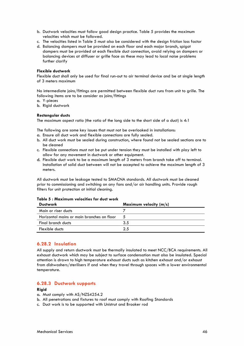
Mechanical Services 46
b. Ductwork velocities must follow good design practice. Table 5 provides the maximum velocities which must be followed.
c. The velocities listed in Table 5 must also be considered with the design friction loss factor d. Balancing dampers must be provided on each floor and each major branch, spigot
dampers must be provided at each flexible duct connection, avoid relying on dampers or balancing devices at diffuser or grille face as these may lead to local noise problems further clarify
Flexible ductwork Flexible duct shall only be used for final run-out to air terminal device and be at single length of 3 meters maximum No intermediate joins/fittings are permitted between flexible duct runs from unit to grille. The following items are to be consider as joins/fittings
Y-pieces Rigid ductwork
Rectangular ducts The maximum aspect ratio (the ratio of the long side to the short side of a duct) is 4:1 The following are some key issues that must not be overlooked in installations:
Ensure all duct work and flexible connections are fully sealed. All duct work must be sealed during construction, where found not be sealed sections are to be cleaned
Flexible connections must not be put under tension they must be installed with play left to allow for any movement in ductwork or other equipment.
Flexible duct work to be a maximum length of 3 meters from branch take off to terminal. Installation of solid duct between will not be accepted to achieve the maximum length of 3 meters.
All ductwork must be leakage tested to SMACNA standards. All ductwork must be cleaned prior to commissioning and switching on any fans and/or air handling units. Provide rough filters for unit protection at initial cleaning. Table 5 : Maximum velocities for duct work Ductwork Maximum velocity (m/s) Main or riser ducts 7 Horizontal mains or main branches on floor 5 Final branch ducts 3.5 Flexible ducts 2.5
6.28.2 Insulation All supply and return ductwork must be thermally insulated to meet NCC/BCA requirements. All exhaust ductwork which may be subject to surface condensation must also be insulated. Special attention is drawn to high temperature exhaust ducts such as kitchen exhaust and/or exhaust from dishwashers/sterilisers if and when they travel through spaces with a lower environmental temperature.
6.28.3 Ductwork supports Rigid
Must comply with AS/NZS4254.2 All penetrations and fixtures to roof must comply with Roofing Standards Duct work is to be supported with Unistrut and Brooker rod

Mechanical Services 47
Flexible Must comply with AS/NZS4254.1
6.29 Air Grilles and Diffusers
6.29.1 General Outlets, grilles and registers must be selected to provide adequate air movement without creating draft. The throw of air diffusers must be selected such that there is no splash on walls above occupied level. Average air velocity in the room must be between 0.1 and 0.15 metres per second. Horizontal and vertical flow patterns and sound power levels must all be checked to ensure compliance with the intent of this standard. All slot diffusers, linear grilles, air boots and light air troffers must have provision for air pattern adjustments such that air can be deflected in a vertical and horizontal direction.
6.29.2 Exhaust Grilles Exhaust grilles must be egg-crate type with a 12 x 12mm core. All exhaust grilles must be complete with integral opposed blade volume control dampers operable through the respective grille face.
6.29.3 Plenum Boxes Plenum boxes must be galvanised steel plenum constructed as for low pressure steel ductwork, insulated internally with minimum 25mm thick (or to NCA, which ever has the higher requirement) internal duct insulation. All joints must be sealed airtight.
6.29.4 Door Grilles Door grilles must be of the, flanged frame type with inverted chevron, sight proof blades with minimum 60% free area. Grilles must comprise fixed horizontal blades, concealed vertical bracing bars where necessary and must be of aluminium construction anodised to the colour to be nominated. Door Grills must not be used in lab environments.
6.29.5 Undercutting of doors Undercutting of doors for return air path is not accepted.
6.30 Filters Deep bed and/or panel filters may be used depending on the air volume and the level of filtration required per the application, consultant is to provide clear PPR requirements for each project on the filtration requirements. Filters must be provided to all outside air fans
6.31 Vibration and Noise
6.31.1 General Must comply with AS 2107 recommended acoustic levels for each space.

Mechanical Services 48
6.31.2 Equipment Statically and dynamically balance equipment and isolate from the building structure. Select vibration isolators with due regard to the weight and speed of the equipment to be isolated and with isolating efficiencies as specified by consultant/designer for the equipment or in any case, not less than 95%. Select springs with a length when loaded approximately equal to their diameter. Provide inertia blocks as required.
6.31.3 Piping Piping must be designed to have sufficient flexibility where connected to vibrating machinery and must be effectively isolated from the building structure where necessary to prevent the transmission of vibration. With respect to the pipework installation to pump sets, for a minimum of 15 metres run there must be anti-vibration, spring mounts, on the supporting brackets. The installation must utilise bends and natural vibration insulation wherever possible to aid the positive vibration isolation steps taken.
6.31.4 Ductwork Ductwork and fitting must be designed and constructed so as to prevent any excessive generation of air noise and vibration of fittings.
6.31.5 Flexible Connections for Pipework Flexible connections must be installed parallel with and horizontal to the shaft of operating equipment wherever possible and of full bore.
6.31.6 Flexible Connections for Ductwork Flexible connections must be fitted to isolate fans and/or conditioner casings from ductwork. Materials and application of flexible connections must be in accordance with AS4254. Flexible connections must be airtight and arranged to permit the renewal of the fabric without disturbing the ductwork or plant. All fabric at the seam must be folded back to conceal raw edges. The flexible connections must have adequate slack to absorb relative movement and vibration of the connected items. Allow flexible connections for ductwork where there are building movement joints. Flexible connection within ceiling spaces must be wrapped with 1 (one) layer of ‘Wavebar’ or equal.
6.31.7 Equipment Inertia Bases All equipment including chillers, boilers, steam generators, heat exchangers, AHU`s, floor mounted fans, pumps, air compressors, vacuum pumps, dryers and VRF units must be mounted on concrete inertia bases specifically sized for total vibration isolation. The pump inertia bases must be fitted with spring isolators specifically selected and manufactured to suit the final pump selection. Each pump set must be complete with flexible connections on the pipework and electrical supplies. These flexible connections must be selected such that they isolate the vibration at source and do not transfer it into the pipework or other connections.

Mechanical Services 49
6.31.8 Building Noise The overall building sound levels in user occupied spaces must be in line with the lower values specified in the current version of AS/NZS 2107. Overall building sound incorporates all noise sources including mechanical and hydraulic systems.
6.32 Fume Cabinets
6.32.1 General Requirements The following equipment is deemed to comply with this standard:
Dynaflow Dynamic Fume Exhaust Systems Conditionaire It is the responsibility of the Fume Cabinet certifier to ensure the cabinet is certified at the time of all mechanical systems operating, The University will not accept the certification of the Fume Cabinet unless all systems are operating as per their design intent.
All components requiring maintenance must be accessible The need for drain points on duct work must be avoided on internal horizontal runs Requirement for pass through ports for power cables to be assessed for each project to allow safe cable reticulation
Cabinet work surface material is to be Trespa TopLab Plus unless otherwise specified Taps\outlets are to be Broen or Enware No fire dampers are to be in fume cabinet exhaust ductwork Systems must be designed to minimise noise and vibration. Automatic sash closing systems are preferred to save energy. Where manual sash systems
are to be installed, a sticker reminding the user to ‘Keep sash low’ must be placed on the unit along with an audible alarm are to be provided.
Labelling on ductwork must be provided Must have VSDs on exhaust fans Refer to VSD section for details of acceptable VSDs Manifolding to be considered as part of design where possible All Fume cabinet controllers are to come with a BACnet interface or are to provide the listed points from the BMCS standard via low level outputs
The Fume Cabinet is to continue to operate during fire mode and the local thermal detector when activate will operate the fume cabinets automatic emergency isolator. The exhaust fan shall continue to run in fire activation, except where a gaseous fire suppressant is utilised.
All penetrations must comply with Usyd roofing and Guttering standard Fume Cabinets must be provided with a Traffolyte label including the cabinet name,
associated fan name and power supply location.
6.32.2 Ducted Fume Cabinets
Must comply with AS2243.8 for all installation, commissioning, clearances and certifications Must discharge at 3 metres above roof line and 6 metres if in vicinity of plant service walkway area (for Heritage buildings an assessment must be undertaken
Must have all points available for monitoring as per BMCS standard Must have 3 metres clearance from any supply or return air grilles and front of sash Must have VSD on exhaust fan Stainless steel to be used in ductwork that pass-through fire compartments within the
building
6.32.3 Wet Decks and Scrubbers Must comply with AS/NZS2243.8

Mechanical Services 50
6.32.4 Manifolded fume cabinet exhaust Risk assessment to be conducted for all connected fume cabinets Large Traffolyte label must be provided on fume cabinet detailing that it is manifolded system and any restrictions on its use
Must comply with AS 2243.8
6.32.5 Ductless or Recirculating Fume cabinets and Laminar flow hoods Must comply with AS2243.9 for all clearances Generally provided and maintained by faculty
6.33 Compressed Air
6.33.1 Air Compressor The following equipment is deemed to comply with this standard:
Atlas Copco Ingersoll Rand Each project must assess the user requirements for air quality based on ISO 8573-1 (water,
oil & solid particulate counts). Suitable filtration and air treatment must be provided to meet the project tool\equipment & user requirements.
Isolation valves must be provided to each piece of equipment including filters, dryers, vessels, building floor take offs, lab take-offs and ancillary equipment.
Pressure gauges are to be provided to the system before and after the main pressure regulator
Auto drain is to be provided on the receiver vessel where external and where a package compressor is provided an auto drain must be provided
For serviceable equipment bypasses must be provided Installation must comply with relevant sections within AS/NZS 2896 where not specified Must be installed and mounted on concrete plinth with vibration suppression systems Compressors to be variable speed where above 20kW Pipework to comply AS/NZS 2896 where not specified Copper pipe work to be utilised unless alternative specified Must provide pressure vessel design certification and pressure vessel certification Pressure vessels must allow for internal visual inspection Oil free compressors only Acoustic treatment must be provided if located internally or near an occupied space The dedicated electrical supply to compressed air system must have a meter installed and connected to the AUMS system
Power isolators must be installed next to equipment A BACnet HLI is to be provided with the equipment (refer to the UI BMCS standard for
required points)
6.34 Painting, Labelling and Colour Schemes
6.34.1 General All pipe work must be clearly labelled. Direction of flow and contents of pipework must be clearly marked on the pipework labelling.
All external duct work must be painted with a primer coat then a finish coat; colour must be selected to ensure ductwork blends in with surroundings.

Mechanical Services 51
6.34.2 Painting Application Prepare surfaces for, and apply paint coatings to, the requirements of clause Corrosion Protection relevant to the application.
The finishing coats must be full gloss enamel, of the colour designated in the following schedule and must be as smooth and free of brush marks as possible.
Thermoset powder coatings must be of full gloss finish and of colour designated in the schedule. Where this requirement is not available from the equipment manufacturer, prepare the powder coat surface with a wash primer or etching solution washed down with clean water and dry thoroughly prior to application of primer and two coats of heavy duty full gloss alkyd finish, all to the requirements of the referenced standards/codes.
6.34.3 Plant Room Floors Plant room floors must be painted in a grey finish in a product that is low VOC, slip and wear resistant, light chemical resistant and oil resistant.
6.34.4 Ductwork subject to Wet or Damp Environment Vertical ducts that are open to weather at the top, and cooling tower, industrial cooler and evaporative condenser discharge ducts, must be internally corrosion protected and painted.
6.34.5 Equipment Colour Schedule Below is a list of University required painting colour schedules for mechanical plants. B15 Mid Blue
Remote Compressors and Motors (excluding coupling guard) Condenser Pumps and Motors (excluding coupling guards) Chilled Water Pumps and Motors (excluding coupling guards) Hot Water Pumps and Motors (excluding coupling guards) Air Compressor, Motor and Receiver (excluding belt guard) Shell and Tube Condenser Liquid Receiver Refrigeration Gauge Panel (exterior) Pneumatic Gauge Panel (exterior)
Y54 Oatmeal
Exposed Ductwork (unless specified to match building/environment) Y35 Off White
Valves, Strainers, etc. Electrical Switchboard / Mechanical Control Board(interior) Refrigeration Gauge Panel (interior) Piping, Excluding Oil Piping, Valves, Strainers, etc.
R13 Signal Red
Coupling Guards Belt Guards Hot Gas Mufflers
Y14 Golden Yellow
Valve Handles

Mechanical Services 52
N52 Mid Grey Plinths, including floating bases
X53 Golden Tan
Heating Piping and heating Storage Vessel Black
Brackets, Drains Brunswick green
Condenser water piping Blue
Chilled water
Silver Grey Steam pipe work
B25 Aqua
Conditioner casing Evaporative Condenser (excluding belt guard) Fans (excluding belt guards)
X15 Orange
Electrical Switchboard / Mechanical Control Board (exterior) Electrical Troughing and Conduits
6.34.6 Equipment Labelling All mechanical equipment must be Traffolyte labelled indicating equipment designation e.g. CHWP-01-01 or AHU 2-5.
Indoor and outdoor labelling must correspond to each other e.g. FCU2-2 and CU2-2.
All filter details including type, quantity and size must be attached in a Traffolyte label to all AHUs, filter bays and ducted fan coil units.
All Belt driven fans must have a Traffolyte label with belt sizes this includes AHUs and FCUs. Equipment must be Asset labelled as per COS Asset Identification and Labelling Standard.
6.34.7 Naming Convention for Traffolyte labels The following standard labelling convention applies:
[Equipment ID – Floor/Level – Count Of #]
e.g. CHWP – L05 – 01
For MSSBs the following standard labelling convention applies:
MSSB – [Essential/Nonessential] - [Location: Level/Floor] – ##
e.g. MSSB – ES – L05 – 01
Example summary of equipment ID for Traffolyte labelling is shown in Table 6.

Mechanical Services 53
Table 6: Equipment Labelling ID
Equipment Equipment ID
Chillers CH
Cooling Towers CT
Pumps (Hot Water, Chilled Water,
Condenser Water)
HWP
CHWP
CDWP
Boilers/Heating Hot Water Generators HHWG
Variable Speed Drives VSD
Variable Air Volume Boxes VAV
Fans – Exhaust Air Fans, Outside Air Fans,
Relief Air Fans
EAF
OAF
RAF
Air Handling Units AHU
Fan Coil Units FCU
Fume Cabinet Exhaust Fan FEX
Make Up Air Unit MAU
Mechanical Services Switch Board MSSB
6.35 Service Access and Safety Requirements
6.35.1 General The following are the University access and service requirements:
Position all equipment and arrange access provisions at equipment, to optimise future maintenance and repairs.
Equipment must not be located in ceiling spaces above labs, animal houses and critical environments. Plant will only be accepted in ceiling spaces within office buildings.
The University will not accept plant within tight spaces. Plant that is located in ceiling space must have free and easy access. This includes ability to service system without reaching around or over columns, beams, cable trays, pipe work, lights and duct work.
All motors are to be provided with isolators within 3 meters distance from motor A plus 20% additional dimension access allowance must be provided above the
manufacturers access requirements for equipment Plant located above 3m height will have permanent stair/ladder access provisions with
permanent workable platform Trip hazards to be identified and painted in yellow Electrical hazards must be identified and labelled appropriately Yellow walkways to be painted around all plant areas in plant rooms Chemical hazards to be labelled and safe clearance lines to be painted on the floor also
appropriate paperwork to be present on-site Confined spaces to be noted and appropriate signage applied Access to plant and equipment must comply with all WHS regulations Where access is within high ceilings that a standard platform ladder cannot reach project must provide access device to allow safe access

Mechanical Services 54
6.36 Redundant Equipment a. All redundant mechanical services and associated services (power, water, drainage, etc)
must be removed as part of the project. Building surfaces and finishes must be made good.
6.37 Product Support and Experience Requirements
All products must be supported locally and internationally by factory trained service networks. All spare parts must be available ex-stock factory for a period of 10 years from purchase date.
Products must comply with Australian Standards and have a proven record of operation within the Australian facilities.
Equipment and associated accessories must be specified as products that have established manufacturing reliability and proven installation history in Australia.
Proven installation history includes products installed and operated for over 10 years and operational costs and detailed life cycle reports must be provided.
All spare parts must be readily available as spares with minimum ordering and delivery times.
7 Commissioning Comprehensive pre-commissioning, commissioning and quality monitoring must be specified by the consultant/designer or contractor. Detailed testing and commissioning records must be provided for each system and each component as appropriate. All such records must be witnessed and verified by the project consultant/head contractor prior to witness commissioning by UI engineers. Project handover plan must be developed by the consultant/designer to allow the system to be handed over to The University. A 12-month building tuning process will commence at Project handover with systems monitored monthly, reported and assessed quarterly, and include assessment of feedback from the occupants. A project specific commissioning plan must be developed and provided to the University for review and approval. UI have developed a Mechanical Services Commissioning Checklist (UI-ENG-F030) which should be used as a minimum guide when preparing the project specific commissioning plan.
8 Safety in Design The contractor must consider risk during the design. A design safety report must be submitted to the relevant UI Project Manager for every design project. Contractors must confirm, so far as it is reasonably practicable, that the structure is without risks to health and safety. Design risks must be considered for the asset lifecycle covering construction, operational and maintenance, refurbishments and decommissioning. The design safety report must include the following:
Description of design element. Description of potential risks and hazards associated with the design element. A low/medium/high risk assessment considering likelihood and consequence.

Mechanical Services 55
Proposed measures to eliminate risks where practicable. Control measures to mitigate and manage design risks. Nominating responsibilities for managing the design risks.
This may be provided as a design risk register where appropriate and must include results of any calculations, testing and analysis etc.
9 Documentation and Records
9.1 Design Documentation Prior to commencing construction of new or refurbishment projects, the consultant/contractor must fully investigate and document the requirements for Mechanical services required to be installed, altered or modified as part of the project works. This must include:
Return brief defining the systems proposed and any deviations from specification and University Standards.
Heat load calculation spreadsheet. Pump and fan Curves. Calculations to be provided on the sizing of the duct work and pipe work. Future allowances are to be included in these calculations/sizing.
Complete services drawings including schematics, plans, sections, penetration details and schedules.
Plant and equipment Acoustic assessment. Equipment support sizing. Equipment seismic restraint calculations. Calculations and selections to be provided on the proposed equipment. Chilled water system low load sizing. Refrigerant concentration calculations. Electrical supply sizing including maximum demand, fault rating and discrimination study. Budget calculations. Designers statutory compliance certificates. Requests for all variations to this standard submitted using the USYD Request for
Dispensation Form (UI-ENG-F001). Complete the Design and Construct checklist using the UI Design and Construct Mechanical Services Checklist document (UI-ENG-F009).
9.2 Completion Documents At the completion of all projects, the following documentation must be provided by the contractor for all Mechanical services installed or altered as part of the project works: The following documents must be provided at practical completion
Maintenance manual including the required maintenance All compliance documentation and certifications Final commissioning records Product manufacturer specific information System schematics (PDF and CAD format). Complete as-built drawings (PDF and CAD format). Electrical and wiring diagrams

Mechanical Services 56
System functionality and operation description System set point values Controls schematic Controls description Controls wiring Details of all usernames and passwords required to access all equipment and software. All equipment selection calculations and schedules Full design documents and calculations (soft copy only) Asset schedules and labelling (as per the Asset Identification and Labelling Standard). Building users’ guide
This documentation must be provided by the contractor in both electronic and hard copy formats and approved by the University prior to Practical Completion being granted.
10 Assets and Warranties Assets are to be tagged in accordance with the Universities Asset & Labelling standard for the purpose of maintenance and operation of University Assets. For refurbishment projects the project manage is to provide the existing asset list to the contractor to ensure modified and redundant equipment are captured in the contractors submitted asset list. Each asset required to be collected can be found in the Form (COS-ASSET-F001), each asset required to be coded will be identified by a unique equipment code. The equipment code will be one the three following types: a. Virtual asset (This is a concatenation Building Code - Floor - Room number) b. Item count asset (This is a concatenation Building Code - Floor - Room number) c. Unique bar code asset (Unique bar code in the million series number affixed to the asset) Asset lists are to be submitted prior to practical completion of the project for review and approval by COS. Equipment Warranties are to be provided for a minimum of 12 months from the date of practical completion. Warranties are to be provided as certificates as part of the O&M from the supplier of the equipment. It is the responsibility of the installation contractor to ensure all maintenance\servicing required to the equipment is provided to ensure warranties are valid at the end of the project DLP
11 Defects and Liability Period Consultants/designers must include in the project specification detailed requirements for the defects and liability period following completion of the fire services installation. The contractor must include and allow for recommissioning of all major plant and equipment in the last month of the 12-month defects and liability period and confirm they achieve the original design requirements. In addition, all commissioning must be witnessed by UI Engineering staff with commissioning reports/results formally submitted to UI Engineering. Where specific items are required to be re-witnessed after PC, the 12-month DLP period will commence from this re-witnessing date.

Mechanical Services 57
11.1 Maintenance and Testing For mechanical services installed as part of a refurbishment project of an existing building, regular statutory maintenance and testing must be carried out by the projects mechanical Services contractor during the Defects Liability Period (DLP). The installation contractor must provide a comprehensive handover and the required completion documentation at Practical Completion. All defects arising from regular statutory/manufacturer maintenance and testing performed during the DLP are the responsibility of the installation contractor. For new buildings, the installation contractor must provide statutory maintenance and testing of all mechanical services and associated statutory testing for the building, throughout the DLP. Prior to the completion of the DLP, the installation contractor will perform all annual maintenance procedures in the presence of the University mechanical services maintenance contractor and provide documentation confirming the provision of all maintenance has been performed during the DLP. In these instances. Any details which will affect the future maintenance and performance of the new or upgraded equipment must be supplied by the installation contractor at Practical Completion. Prior to completion of the DLP, a final inspection of the installed systems will be carried out by the: installation contractor, appropriate UI and COS staff, and University essential services maintenance contractor, in order to reconcile the performance of the equipment during DLP to produce a final list of project defects. All project defects identified must be rectified by the installation contractor prior to finalisation of the DLP.
12 Operations & Maintenance Manuals Consultants/designers must include in the project specification detailed requirements for operation and maintenance manuals, including system description, operation procedures, testing and commissioning records, maintenance instructions, product support information and recovery protocols for any computer related systems. Contractors must provide these to the satisfaction of the consultant/designer. Providing a collection of manufacturers’ brochures and catalogues is not acceptable to the University. Discuss with UI to understand what format to submit the O&M Manuals. Typical submissions come via soft copy (editable) and used via a system like Aconex. Contractors must submit the university designed Asset Management Master Asset Data Capture Spreadsheet (COS-ASSET-F001) designed for recording operational and maintenance activities including materials used, test results, comments for future maintenance actions and notes covering asset condition. Completed logbook pages recording the operational and maintenance activities undertaken for Practical Completion and during the Defects Liability Period must also be provided. Facilities Maintenance must establish, document and implement procedures for operation and maintenance of mechanical services, plant and equipment to ensure mechanical services are fit-for-purpose, provide secure, efficient, safe and reliable electrical power, and comply with requirements of this standard.
Mechanical Services 58
13 Authorisation of Variations Project managers, consultants, contractors, commissioning agents and facilities maintenance personnel must ensure compliance with these requirements is achieved.
Variations to this standard must only be considered where: a. The University Standard’s requirement cannot physically or technically be achieved. b. The alternative solution delivers demonstrated and proven superior performance for the
same capital and life cycle cost or better. Consultants and contractors must identify and justify requirements of the standard that do not apply to the project or which need to be varied and these which must be approved by the issuer of this standard. Formal requests for all variations to this Standard must be submitted using the Request for Dispensation Form (USYD-ENG-F001). The issuer of this standard or their delegated authority must review and consider requirements of stakeholders from clients, projects and facilities management before deciding whether to approve variations. Their formal sign-off is required for acceptance of any non-compliances and departures from this standard’s requirements.
14 Quality Control 14.1 Design Standard Compliance Compliance with requirements of this standard must be checked throughout the design, construction and commissioning phases of projects by UI’ services consultant. Any issues or deviations from this standard must be reviewed and approved in writing by the issuer of this standard. Competent UI consultants and representatives must check compliance with this standard during design reviews and formal site inspections. Any non-conformances with requirements of this standard must be documented and provided to the UI Project Manager for issue to contractors and their consultants. Project Managers must maintain a formal register of non-conformances and manage close out of outstanding non-conformances. Contractors and their consultants issued with non-conformances must take appropriate corrective actions. The UI Project Manager must ensure: a. Proposed corrective actions are implemented. b. Close out of non-conformances in relation to this standard is formally approved and signed
off by the author of the standard or their delegate.
14.2 Design Standard Certification Contractors and Consultants must certify compliance to the design standard by submitting a company Design Certification Form to the UI Project Manager at each of the following project phases: a. Design and Documentation. b. Tender. c. Construction. Notwithstanding UI’s internal quality control processes, contractors and their consultants must implement their own robust quality assurance and control procedures to ensure compliance with requirements of this standard.

Mechanical Services 59
14.3 Construction Compliance Consultants and contractors are expected to include check sheets for each system component detailing each item that needs to be checked, tested and verified during the installation process. Such check sheets must be completed and verified by the project consultant/contractors, including the identification of any defects and the closing out of such defects.
14.4 Acceptance The University will only accept projects as complete when all of the above have been carried out, submitted and verified. The above standards are not an exhaustive list of the relevant requirements. The consultant/contractor must incorporate all relevant standards and Authorities requirements into project specific design, documentation and installation.
15 Document Amendment History Revision Amendment Commencing 001 First Issue 16 August 2013 002 2 Year Revision
5.10 added EMC & THD compliance. 5.12 plant room clause added. 5.14 Air handling unit’s clause added. 5.15 chilled\hot water fan coil section added. 5.17chilled\hot\condenser water valve clause added. 5.20 Motor control centres and mechanical switch boards clause added. 5.21 Water cooled Package unit’s clause added. 7 Safety in design clause added. New Forms added to the website; UI Design & Construct Services Checklist Form (UI-ENG-F009)
18 September 2015
3.0 5 Year revision a. Through projects lessons learnt, industry and
consultant feedback we have updated the requirements in the standards where they had a cost impact to align with industry practice as well ensuring any items that are being kept in the standards that are above industry standard level have an ROI.
b. Project Definition stage added at 5.1. referring to Project “Gate Paper” and requirement for site inspection / briefing. Requirement for “Return Brief” formalised.
c. Documents required for Submission & Approval updated, tightened up, aggregated and clarified.
d. Safety in Design legislation reinforced. e. Commissioning Checklists added. f. Supersession of Codes & Standards between
project initiation and execution is addressed. A
26 August 2020

Mechanical Services 60
Revision Amendment Commencing major issue immediately and ongoing given long project gestations.
g. Scope / Technical cover increased to include; h. Low load operation updated i. Fire Dampers section added j. Boiler section added k. Humidifier section added l. Dehumidifier section added m. Air Compressor section added n. Metering coverage updated o. Fume Cabinet section added p. Ductwork support requirements updated q. VSD requirements updated r. Plant and equipment servicing clearances updated
as per Facilities management team requirement s. Air Handling Unit section updated t. Equipment manufacturers updated u. Defects period maintenance; include requirements
for maintenance and testing during DLP v. Documentation and Records section updated to
include new requirements w. Equipment Labelling requirements included x. Service Access and Safety Requirements section
included y. Building tuning section updated to clarify Usyd
requirements for tuning period in DLP z. Asset and Warranties section updated aa. Asset Standard Owner is now COS.