Embed Size (px)
Citation preview

Graduate Theses and Dissertations Iowa State University Capstones, Theses andDissertations
2012
Mechanics of magneto-active polymersYi HanIowa State University
Follow this and additional works at: https://lib.dr.iastate.edu/etd
Part of the Engineering Mechanics Commons, Mechanical Engineering Commons, and theMechanics of Materials Commons
This Dissertation is brought to you for free and open access by the Iowa State University Capstones, Theses and Dissertations at Iowa State UniversityDigital Repository. It has been accepted for inclusion in Graduate Theses and Dissertations by an authorized administrator of Iowa State UniversityDigital Repository. For more information, please contact [email protected].
Recommended CitationHan, Yi, "Mechanics of magneto-active polymers" (2012). Graduate Theses and Dissertations. 12929.https://lib.dr.iastate.edu/etd/12929

Mechanics of magneto-active polymers
by
Yi Han
A dissertation submitted to the graduate faculty
in partial fulfillment of the requirements for the degree of
DOCTOR OF PHILOSOPHY
Major: Engineering Mechanics
Program of Study Committee:
Wei Hong (Major Professor)
LeAnn E. Faidley
Ashraf Bastawros
Thomas J. Rudolphi
Pranav Shrotriya
Iowa State University
Ames, Iowa
2012
Copyright © Yi Han, 2012. All rights reserved.

ii
TABLE OF CONTENTS
LIST OF FIGURES iv
ABSTRACT ix
CHAPTER 1 INTRODUCTION 1
1.1 Literature review 1
1.2 Motivation 8
1.3 Structure of the dissertation 9
CHAPTER 2 COUPLED MAGNETIC FIELD AND VISCOELASTICITY OF
FERROGELS
11
2.1 Introduction 13
2.2 Stress and magnetic field 13
2.3 Non-equilibrium thermodynamics 17
2.4 A specific constitutive model 22
2.5 Finite-element implementation 25
2.6 Numerical examples 27
2.6.1 A quasi-uniform magnetic field 28
2.6.2 A non-uniform magnetic field 31
2.6.3 Cyclic response induced by an electromagnet 35
2.7 Concluding remarks 37
CHAPTER 3 FIELD-STIFFENING EFFECT OF MANETO-RHEOLOGICAL
ELASTOMERS
38

iii
3.1 Introduction 38
3.2 Dipolar interaction in a wavy particle-chain 42
3.3 Material model and numerical calculation 48
3.4 Results and discussion 53
3.5 Concluding remarks 63
CHAPTER 4 A HOMOGENEOUS MODEL OF MAGNETOSTRICTION AND
MAGNETO-RHEOLOGICAL EFFECT
65
4.1 Introduction 65
4.2 Fields definition 67
4.3 Incompressibility and free-energy 71
4.4 Effective permeability 73
4.5 Magnetostriction 75
4.6 MR effect 79
4.7 Concluding remarks 81
CHAPTER 5 CONCLUSIONS 83
BIBLIOGRAPHY 86
ACKNOWLEDGEMENTS 98
PUBLICATIONS 100
iv
LIST OF FIGURES
Figure 1.1 Microstructure of isotropic (a) and anisotropic (b) MAPs (adopted form
Chen et al., 2007).
4
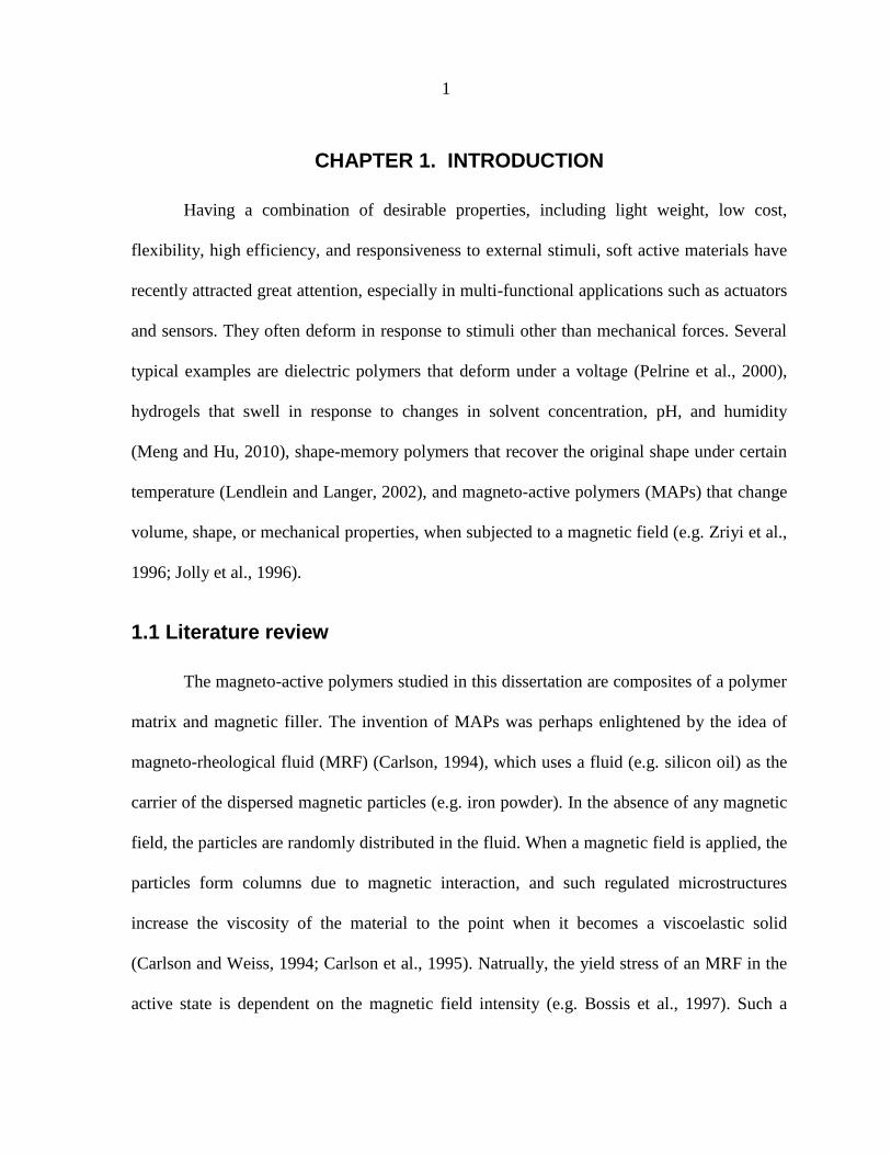
Figure 1.2 The MR effect in the shear deformation. The change in the shear modulus
increases with respect to the applied magnetic field as well as the volume
fraction of magnetic particles (adopted from Jolly et al., 1996).
6
Figure 1.3 The MR effect in the tensile modulus. The modulus increases with respect
to the applied magnetic field and the weight fraction of magnetic particles
(adopted from Varga et al., 2006).
7
Figure 2.1 Sketch of a ferrogel under combined mechanical and electromagnetic
loads. P indicates the external mechanical load applied by a weight and I
is the current input to the ferrogel by a current source. (Han et al., 2011)
14
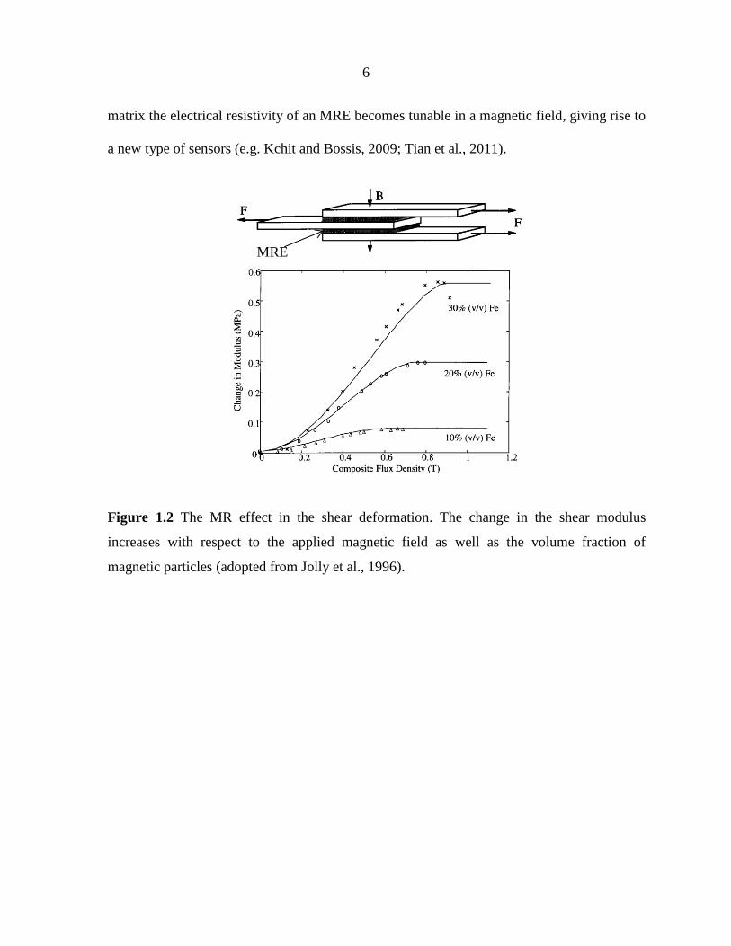
Figure 2.2 A physical deformation is decomposed into two parts through imagining
an intermediate state, in which every material particle is elastically
relaxed. The fully relaxed material particles in the intermediate state do
not need to constitute a continuum body. The inelastic stress in the current
state is assumed to be a function of the elastic deformation gradient eF
only. (Han et al., 2011)
19
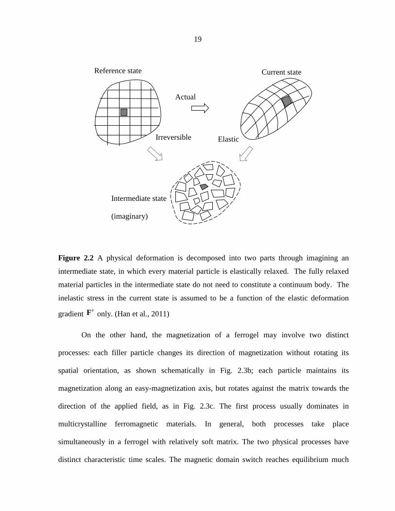
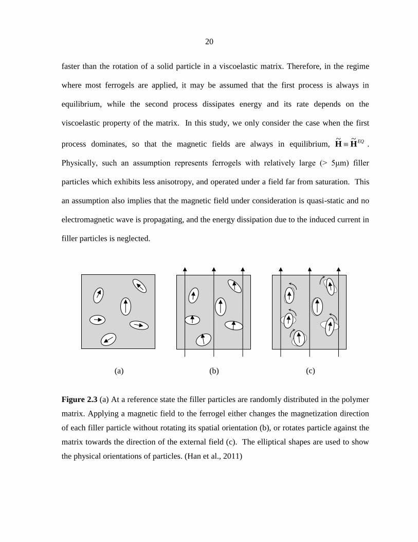
Figure 2.3 (a) At a reference state the filler particles are randomly distributed in the
polymer matrix. Applying a magnetic field to the ferrogel either changes
the magnetization direction of each filler particle without rotating its
spatial orientation (b), or rotates particle against the matrix towards the
direction of the external field (c). The elliptical shapes are used to show
the physical orientations of particles. (Han et al., 2011)
20
Figure 2.4 (a) A ferrogel sample is placed inside a solenoid. (b) The magnetic field is
slightly perturbed by the ferrogel due to coupling. The color scale
indicates the axial stretch 3 . (c) The BH ~ curve is close to linear and
demonstrates an insignificant hysteresis. (Han et al., 2011)
29

v
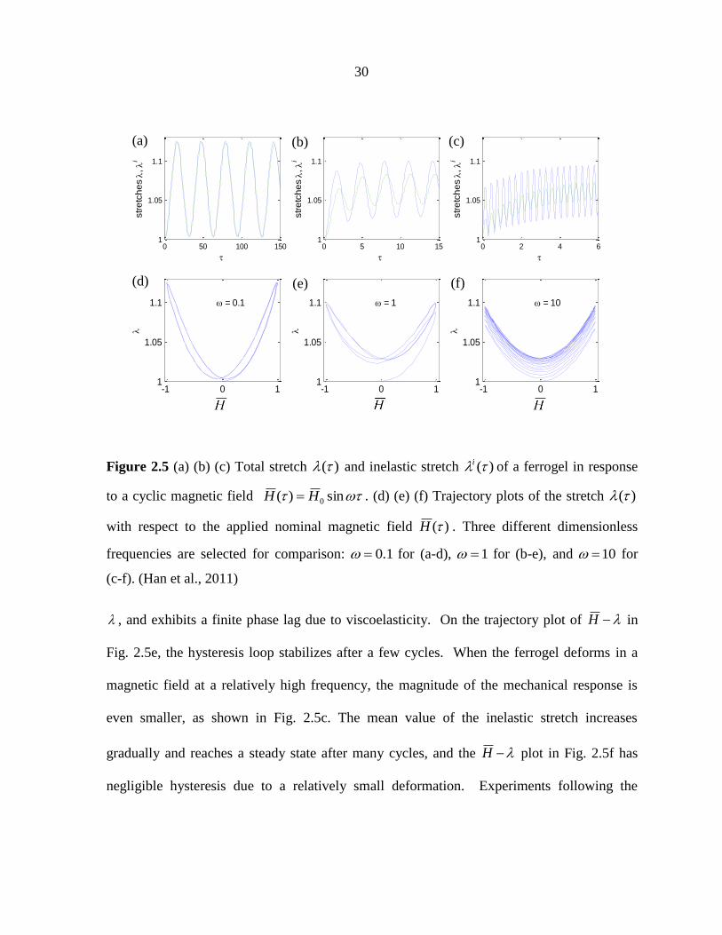
Figure 2.5 (a) (b) (c) Total stretch )( and inelastic stretch )(i of a ferrogel in
response to a cyclic magnetic field sin)( 0HH . (d) (e) (f)
Trajectory plots of the stretch )( with respect to the applied nominal
magnetic field )(H . Three different dimensionless frequencies are
selected for comparison: 1.0 for (a-d), 1 for (b-e), and 10 for
(c-f). (Han et al., 2011)
30
Figure 2.6 (a) A nonuniform magnetic field is produced by two electromagnets to
drive large deformation of a ferrogel. (b) Part of a 2-D model that captures
the elongation of the ferrogel. The color scale indicates the longitudinal
stretch . (c) The stretch as a function of the applied field. Several
values of the viscoelastic parameters are used. (d) An instability
phenomenon as captured by an elastic model. (Han et al., 2011)
33
Figure 2.7 (a) Sketch of experimental setup. (b) The ferrogel is shortened
longitudinally and expands laterally due to gravity and the magnetic field.
The color scale indicates the longitudinal stretch . Numerical results in
terms of the average axial strain are compared with experiments in the
time domain (c) and in the frequency domain (d). (Han et al., 2011)
36
Figure 3.1 Schematics of three possible mechanisms of the field-stiffening effect in
an MRE: (a) dipolar interaction between particles in a straight chain, (b)
dipolar interaction in a wavy particle chain, and (c) non-affine
deformation of the polymer matrix. The geometric parameters are the
particle diameter d , the horizontal distance b , and the vertical distance h
between two neighboring particles.
40
Figure 3.2 Dimensionless contribution to the tensile modulus from magnetic dipole
interactions, plotted as a function of the geometric parameter hb (the
waviness of a chain). Both the nearest-neighbor approximation (dash
curve) and the result with interactions from all particles (solid curve) are
presented.
45
Figure 3.3 Dimensionless contribution to shear modulus from magnetic dipole
interactions, plotted as a function of the geometric parameter hb .
The results depend on the relative direction of the shear-induced rotation
46

vi
and the direction of dipole moments. In the case when the dipoles stay in
the original direction (case 1), a straight chain ( 0 ) has stiffening
effect in shear, but a wavy chain of intermediate values softens under a
magnetic field. In the case when the dipoles follow the shear-induced
rotation (case 2), a wavy chain shows stiffening effect at intermediate
values of .
Figure 3.4 (a) Sketch of an MRE with the magnetic field applied through an
electromagnetic coil. (b) Sketch of a representative unit cell with a wavy
chain. Periodic boundary conditions with constant offsets are applied on
the displacements of all four edges of the unit cell.
51
Figure 3.5 Stiffening effect in the tensile modulus of MREs with different chain
geometries: (a) straight chains ( 0 ) only give softening effect, which
becomes weaker as the inter-particle distance increases; (b) wavy chains
of intermediate values have positive field-stiffening effect.
55
Figure 3.6 (a) Stiffening effect in the shear modulus of MREs with different chain
geometries: straignt chains ( 0 ) give the strongest stiffening effect and
wavy chains ( 0 ) also induce positive stiffening effect. (b) Rotation of
the particle chains and the magnetization in filler particles due to a shear
deformation. The color scale shows the magnitude of the dimensionless
true magntic field, and the arrows show the directions of the
magnetization field.
56
Figure 3.7 Two representative microstructures of MREs containing particle chains of
finite lengths: (a) chains are parallel and side by side, and (b) chains are
staggered. The computational unit cells are marked by dash lines.
58
Figure 3.8 Simulated non-affine deformation in unit cells under magnetic fields: the
inter-particle distance is narrowed and the inter-chain gap is stretched. The
magnetic induction field is shown by streamlines, and the vertical stretch
is shown by color scale.
58
Figure 3.9 Relative change in tensile modulus of MREs containg straight chains
arranged side by side or staggered. All geometris show a field-softening
effect. The effect becomes weaker as the gap size increases.
60

vii
Figure 3.10 (a) Change of tensile modulus plotted as a function of the normalized true
magnetic field, for MREs of various filler volume fractions. The
numerical results fit well to a quadratic relation, 2
0HE (solid
curves). (b) The dimensionless quantity 2
0HE from the fitting results,
is approximately linear in filler volume fraction, .
62
Figure 4.1 Sketch of a cylindrical MAE surrounded by a flexible coil. A constant
current I passes through the coil to generate a uniform magnetic field
through the elastomer. In the reference state, the elastomer has a length,
L and a radius, R . Under a deformed state, the dimensions change to l
and r , respectively.
68
Figure 4.2 Representative sketches of strain dependent effective permeability of
MAEs with three different microstructures. The permeability maintains as
a constant when the particles are randomly dispersed in the polymer-
matrix (a), but varies distinctly with respect to the strain, 1 , when the
particles are aligned into straight chains (b) and zig-zag chains (c).
75
Figure 4.3 (a) The schematic drawing of a cylindrical MAE placed inside an
electromagneto coil. A constant direct current I passes through the coil
generating a uniform magnetic field when the MAE is absent. (b) After
the insertion of an MAE, the magnetic field is perturbed. The streamlines
show the distribution of the magnetic field H , which is quasi-uniform
through the MAE body.
77
Figure 4.4 The magnetostriction of MAEs as functions of the square of a
dimensionless magnetic field. The dashed curves represent
magnetostriction of isotropic MAEs of three values of the effective
permeability, while the solid curves represent the magnetostriction of
anisotropic MAEs. The square symbols are experimental data taken from
Ref (Coquelle and Bossis, 2005).
79
Figure 4.5 The MR effect in the tensile modulus as a function of the applied
magnetic field. The solid curves are calculated E of MAEs with zig-zag
chains of three values of the effective permeability. The dashed curve is
calculated E of MAEs with straight chains. The square, triangle and
81

viii
circular symbols represent experimental results of three different volume
fractions of iron particles taken from Ref (Varga et al., 2006).

ix
ABSTRACT
Magneto-active polymers (MAPs) are polymer-based composites that respond to
magnetic fields with large deformation or tunable mechanical properties. While a variety of
these materials exist, most are composites of a soft polymer matrix with a filler of magnetic
particles. The multi-physics interactions in MAPs give them two very attractive features.
First, they respond to a magnetic field with variable mechanical properties (e.g. stiffness).
Second, their shape and volume may be significantly changed in a magnetic field. Both
features could be tuned by engineering the microstructure of the composites. Potential
applications of MAPs include sensors, actuators, bio-medicine, and augmented reality.
However, their potential has not been fully uncovered, partly due to the limited
understanding in the mechanisms driving the coupled multi-physics behaviors, and the lack
of a quantitative tool to predict their response under various loading and boundary
conditions. This study aims to enhance the understanding of mechanics of MAPs, by
developing theroies and models which can explain and predict several primary features of
these materials.
First, the viscoelastic behaviors of ferrogels, one class of MAPs, in response to
different magnetic fields are studied. A ferrogel is composed of gel-like matrix and magnetic
particles that randomly distribute in the matrix. Due to the viscoelasticity of the gel-matrix,
ferrogels usually demonstrate rate-dependent behaviors. However, very few models with
coupled magnetic field and viscoelasticity exist in the literature, and even fewer are capable
of reliable predictions. Based on the underlying principles of non-equilibrium
thermodynamics, a field theory is developed to describe the magneto-viscoelasticity in solids.
The theory provides a guideline for experimental characterizations and structural designs of

x
ferrogel-based devices. A specific material model is then selected, and the theory is
implemented in a finite-element code. As numerical examples, the responses of a ferrogel in
uniform and non-uniform magnetic fields are respectively analyzed. The dynamic response
of a ferrogel to cyclic magnetic fields is also studied, and the prediction agrees with our
experimental results. In the reversible limit, our theory recovers existing models for elastic
ferrogels, and is capable of capturing some instability phenomena.
Second, the mechanism of the stiffening effect in magneto-rheological elastomers
(MREs), a class of anisotropic MAPs, is investigated. MREs tend to be mechanically stiffer
under a magnetic field. Such a stiffening effect is usually referred to as the magneto-
rheological (MR) effect and often attributed to the magnetic interaction among filler
particles. But the well-acknowledged dipole-interaction model fails to explain the stiffening
effect in tension/compression, which was observed in experiments. Other mechanisms, such
as the effect of non-affine deformation, have also been proposed, but there is no conclusive
evidence on the dominating mechanism for the MR effect. This study investigates various
chain structures, and seeks to identify the ultimate origin of the stiffening effect in MREs.
Two different methods are used for cross verification: a dipolar interaction model and a finite
element simulation based on continuum field theories. Both the shear and axial deformation
of the material are studied, with a magnetic field applied in the particle-chain direction. It is
found that while the magnetic interaction between particles is indeed the major cause of the
stiffening effect, the wavy chain structure is the key to the modulus increase. Besides, chain-
chain interaction and non-affine deformation are shown to be insignificant. In addition, the
dependence of the stiffening effect on filler concentration is calculated, and the results

xi
qualitatively agree with experimental observations. The models also predict some interesting
results that could be easily verified by future experiments.
Third, a simpler and easy-to-use homogenenous model is further developed to predict
the magnetostriction and the MR effect of MAPs subjected to a uniform magnetic field. In
general, the magnetic permeability of a MAP varies during a deformation due to the change
of the microstructure. The strain dependence of permeability has been discussed for MAPs
with various microstructures. It is shown that when the magnetostriction is primary caused by
the difference in the permeability of an MAP and its surrounding media, the MR effect is due
to the change of the permeability under a strain. Besides, it is found that both the
magnetostriction and the MR effect are microstructure dependent. When the magnetostriction
is more significant in isotropic MAPs, the MR effect only exists in anisotropic MAPs. In
addition, it is shown that only the materials with wavy particle chains are possible to exhibit
MR effect in tensile modulus.
1
CHAPTER 1. INTRODUCTION
Having a combination of desirable properties, including light weight, low cost,
flexibility, high efficiency, and responsiveness to external stimuli, soft active materials have
recently attracted great attention, especially in multi-functional applications such as actuators
and sensors. They often deform in response to stimuli other than mechanical forces. Several
typical examples are dielectric polymers that deform under a voltage (Pelrine et al., 2000),
hydrogels that swell in response to changes in solvent concentration, pH, and humidity
(Meng and Hu, 2010), shape-memory polymers that recover the original shape under certain
temperature (Lendlein and Langer, 2002), and magneto-active polymers (MAPs) that change
volume, shape, or mechanical properties, when subjected to a magnetic field (e.g. Zriyi et al.,
1996; Jolly et al., 1996).
1.1 Literature review
The magneto-active polymers studied in this dissertation are composites of a polymer
matrix and magnetic filler. The invention of MAPs was perhaps enlightened by the idea of
magneto-rheological fluid (MRF) (Carlson, 1994), which uses a fluid (e.g. silicon oil) as the
carrier of the dispersed magnetic particles (e.g. iron powder). In the absence of any magnetic
field, the particles are randomly distributed in the fluid. When a magnetic field is applied, the
particles form columns due to magnetic interaction, and such regulated microstructures
increase the viscosity of the material to the point when it becomes a viscoelastic solid
(Carlson and Weiss, 1994; Carlson et al., 1995). Natrually, the yield stress of an MRF in the
active state is dependent on the magnetic field intensity (e.g. Bossis et al., 1997). Such a

2
magneto-rheological (MR) effect gives rise to applications such as vibration controllers and
dampers (e.g. Carlson, 1994; Li et al., 2000, 2003; Hitchcock et al., 2007; Bossis et al., 2002;
Claracq, et al., 2004; Wang and Gordaninejad, 2006; Yang et al., 2009). However, MRFs
suffer from sedimentation due to the liquidous carrier. To overcome this drawback, MAPs
with polymers as matrices have been developed. The magnetic particles are locked into
specific positions in an MAP at the time of curing and would not settle. MAPs have been
studied under a variety of names and for a variety of different applications over the past
several decades. This section will review the background that directly motivates the research
conducted for this dissertation.
Various polymers have been adopted as the matrix material to synthesize MAPs, such
as poly(vinyl) alcohol (PVA) hydrogels (Zrínyi et al., 1996; Varga et al., 2006; Failey et al.,
2010), alginate gel (e.g. Zhao et al., 2011), natural and synthetic rubber (Carlson and Jolly,
2000), silicon elastomers (Zhou et al., 2003), polyurethanes (e.g. Carlson and Jolly, 2000;
Wu et al., 2010) and thermoplastic polymer (Zajac et al., 2010). Typical magnetic particles
used as the filler of MAPs are soft magnetic materials, such as iron particles in micron size
(e.g. Jolly et al., 1996), carbonyl iron powder (e.g. Varga et al., 2006; Faidley et al., 2010),
and nanoscale iron particles (Zrínyi et al., 1996; Zhao et al., 2011). The behavior of MAPs
interacting with external magnetic fields can be understood by considering the behavior of
the filled particles when exposed to a field and constrained by the matrix materials
simultaneously. For example, in a very soft matrix, such as a gel, the magnetic particles will
be driven to the region of the highest gradient of the field causing the matrix material to
move together with them and creating a bulk strain in the sample. On the other hand,
particles embedded in a stiffer elastic matrix will attract each other when exposed to a

3
uniform field thus creating internal forces and increasing the effective stiffness of the sample.
In general, the MAPs to be studied in this dissertation can be devided into two categories
based on the property of the matrix materials, as summarized in Tab 1.
Table 1. Summary of MAP types
Common Name Matrix
Material
Mechanical
Property
Typical
Microstructure
Primary Field-
Driven Behavior
Ferrogel Gel Viscoelastic Isotropic Strain
Magneto-
rheological
elastomer
Elastomer Elastic Anisotropic Stiffness change
Ferrogels usually consist of a soft gel matrix with magnetic particles in micro- or
nano-meter size. Generally the particles are randomly dispersed in the matrix (Fig. 1.1a)
enduing ferrogels isotropic elasticity and magnetic sensitivity. When a ferrogel is placed in
an external magnetic field, forces act on the filler particles and the magnetic interaction is
enhanced. The magnetic field drives particles, together with the polymer network, moveing
towards to the highest field. Depending on the geometrical arrangement, elongation (Zrínyi et
al., 1996), contraction (Snyder et al.,2010a), bending and rotation (Snyder et al.,2010a;
Nguyen & Ramanujan, 2010) can be achieved. Thus there is a distinctive way to creat the
motion by magnetic field without any direct contact. Besides, the ferrogels move smoothly
and scilently in a wide range of motions with rapid response capability and precise
controllability. These magnetocontrolled soft and swellable gels are promising materials in
the growing family of stimuli-responsive gels and actuators. In the past decades, ferrogels
have received developments on a variety of changes in shape (Zrínyi et al., 1996; Snyder et
al., 2010a; 2010b), water retention (Liu et al., 2006a; Filipcsei et al 2007; Hernández et al.,

4
2010), stiffness (Misumata et al., 1999; Varga et al 2006) and viscoelasticity (Zrínyi et al.,
1998; Hernández, 2004; Hernández et al., 2010; Faidley et al., 2010) under magnetic fields.
For examples, strains up to 40% are reported in a ferrogel formed of PVA crosslinked with
glutardialdehyde (GDA) and swollen with a ferrofluid under non-uniform magnetic field of
0.8T (Zriyi et al., 1996); dynamic study on a ferrogel synthesized with PVA gel with
carbonyl iron power shows its rate-dependent deformation under a non-uniform field
saturates at about 1 Hz (Faidley et al., 2010). When the gel matrix is made to be porous,
ferrogel-based magnetic foams are developed (Liu et al., 2006a). These materials respond to
a magnetic field with drastic change in both the volume and the shape resulting in
applications for controllable drug delivery systems (Liu et al., 2006b; Zhao et al., 2011).
Figure 1.1 Microstructure of isotropic (a) and anisotropic (b) MAPs (adopted form Chen et
al., 2007).
Magneto-rheological elastomers (MREs), orginially developed as sensors for axial
and rotational strains (Rigbi & Jilkén, 1983), have primarily received interest for vibration
mitigation applications due to their tunable stiffness. Unlike ferrogels, in MREs the magnetic
particles are usually engineered into chain structures (Fig. 1.1b), by applying an external
(a) (b)
Polymer
matrix
Particles Particle chains

5
magnetic field during the curing process. The chain strucutres are locked upon the final cure
making both the microstructure and magneto-mechanical property of MREs to be
anisotropic. When an MRE is placed in a uniform magnetic field, the interactions between
particles in a chain enhance the permeability and increase the effective stiffness of the
material. Experimental observations have found that both the shear modulus (e.g. Jolly et al.,
1996; Zhou, 2003; Chen et al., 2007) and tensile modulus (e.g. Bellan & Bossis, 2002; Varga
et al., 2006; Abramchuk et al., 2007) of these materials increase under a magnetic field, as
shown in Fig. 1.2 and 1.3 respectively. Such magnetotunable stiffness enables MREs in a
variety of applications as variable stiffness bushings (Lerner, 2005), engine mounts (Ginder,
1996) and releasable attachments (Ottaviani et al., 2006) used in the automotive industry;
tunable vibration absorbers and damping components (e.g. Ginder et al., 2000; Deng et al.,
2006; Lerner and Cunefare, 2008; Hoang et al., 2011), and noise control devices (Farshad &
Roux, 2004). The behavior that the stiffness of MREs increases under a magnetic field is
usually reffered to as MR effect. Theoretical models are developed to explain the MR effect,
most of them consider each particle exposed to a magnetic field as a magnetic dipole and
believe that the MR effect is attributed to the dipolar interaction (e.g. Jolly et al., 1996;
Ivaneyko et al., 2011; Stolbov et al., 2011). A large number of experiments have been carried
out to study the effect of matrix and filler composition (e.g. Bellan and Bossis, 2002; Nikitin
et al., 2006; Lockette et al., 2011), relative alignments of particles, mechanical, magnetic
inputs (e.g. Varga et al., 2006; Filipcsei et al 2007; Rao et al., 2010;), frequency of
mechanical and magnetic loads (e.g. Zhou, 2003; Bolm & Kari, 2005; Stepanov et al., 2007;
Li et al., 2010; Gong et al., 2012). Beside the MR effect, by adding graphite powder into the
6
matrix the electrical resistivity of an MRE becomes tunable in a magnetic field, giving rise to
a new type of sensors (e.g. Kchit and Bossis, 2009; Tian et al., 2011).
Figure 1.2 The MR effect in the shear deformation. The change in the shear modulus
increases with respect to the applied magnetic field as well as the volume fraction of
magnetic particles (adopted from Jolly et al., 1996).
MRE

7
Figure 1.3 The MR effect in the tensile modulus. The modulus increases with respect to the
applied magnetic field and the weight fraction of magnetic particles (adopted from Varga et
al., 2006).
Magnetostriction, initially observed from ferromagnetic metals and alloys (Clark and
Belson, 1983; Wun-Fogle et al., 1999), has been captured in both ferrogels and MREs under
a uniform magnetic field. Due to the relatively low stiffness of the matrix matrials, the
magnetostriction in MAPs can be 103 times larger than that in alloys (Bednarek 1999). For
example, 1.5% magnetostriction stain is obtained from a MAP composed of silicon elastomer
and iron particles at a volume ratio of 10% under a magnetic field of 120kA/m (Coquelle and
Bossis, 2005), while only micro-strain can be obtained from alloys. Magnetostriction,
together with the finite deformation under a non-uniform field, enables MAPs a wide range
of applications as actuators. Experiments have been carried out to study the effect of
microstructure dependence (Ginder et al., 2002; Martin et al., 2006), relative particle
Magnetic field (Gauss)
Ten
sile
modulu
s (K
Pa)

8
alignments and magnetic field (Guan et al., 2002; Danas et al., 2012) and mechanical inputs
(Danas et al., 2012). A few models are developed based on the magnetic dipolar interaction
theory to explain the magnetostriction of isotropic MAPs (Diguet et al., 2009; Stolbov et al.,
2011).
1.2 Motivation
Though the viscoelastic behavior of MAPs has been widely demonstrated through
experiments, very few models exist in the literature can couple the magnetic field and the
viscoelasticity, and one can predict the three-dimensional dynamic behavior of MAPs even
does not exist. Linear viscoelastic models such as Maxwell and Kelvin-Voigt models have
been used to capture the dynamic responses of MAPs, as reviewed by Spencer Jr. et al.
(1996). However, these simple rheological models are limited to small deformations in one
dimension. Therefore, to develop constitutive relations describing the coupling of magnetic
field and viscoelasticity is important to understand and predict the behaviors of MAPs and
becomes the first objective of this study.
Constant efforts have been paid to study the mechanism of MR effect in MREs for a
long time. The most widely used models in the literature are based on the dipolar interaction
theory, which consider each particle as a magnetic dipole in an applied field and assume all
particles in MREs are aligned into straight chains (e.g. Jolly et al., 1996; Shen et al., 2004;
Stolbov et al., 2011). However, these models can explain the MR effect of the shear modulus,
but not that of the tensile modulus. Besides the dipolar interaction, some other mechanisms
have also been claimed, such as non-affine deformation and chain-chain interaction (e.g.
Kankanala and Triantafyllidis, 2004; Yin and Sun, 2005; Ivaneyko et al., 2011; Stolbov et al.,

9
2011). However, theoretical or experimental approves of these possible mechanisms are still
lacking, which naturally motivates the second objective of this study: to identify the ultimate
mechanism of the MR effect.
In addition, contradiction exists between the experiments and theories for
magnetostriction of MAPs. Kankanala and Triantafyllidis (2004) claimed that under a
magnetic field, the particles in a chain of anisotropic MAPs attract their neighbors, leading to
a contraction of the chain, and thus to a global negative magnetostriction. On the contrary, as
discussed in Section 1.1, elongations of anisotropic MAPs are observed in experiments.
Though a few models have been developed to predict the magnetostriction, they are limited
to isotropic MAPs only (Diguet et al., 2009; Stolbov et al., 2011). Thus the third objective of
this study is to develop a general model which can explain the magnetostriction in both
isotropic and anisotropic MAPs and can be verified by comparing with existing experimental
results.
1.3 Structure of the dissertation
This dissertation is organized as follows. In Chapter 2, a field theory is developed to
couple the magnetic field and viscoelasticity in solids. To utilize the theory, a material model
is specified and the weakform is derived for finite-element implementation. Three different
boundary value problems are studied as numerical examples of our model. Chapter 3
investiges various possible mechanisms that cause the MR effect of MREs using two
methods. First, the dipole-interaction model is used to verify the magnetic contribution of
various microstructures to the stiffness of MREs. Then the field theory-based finite-element
simulation is conducted for cross-verification. Besdies, the finite-element model is also used

10
to study the contribution of other mechanisms, such as the non-affine deformation and chain-
chain interaction. Chapter 4 develops a homogeneous model to predict the magnetostriction
and the MR effect of MAPs. A general case, cylindrical MAPs are subjected to a uniform
magnetic field, is discussed. The magnetic permeability of MAPs is proposed as a function of
the axial strain, and the strain dependence is discussed for MAPs with various
microstructures. Besides, the effect of microstructure on the magnetostricion and MR effect
is discussed. As demonstrations, experimental results of magnetostriction (Coquelle and
Bossis, 2005) and the MR effect (Varga et al., 2006) are fitted by the model.

11
CHAPTER 2. COUPLED MAGNETIC FIELD AND VISCOELASTICITY
OF FERROGELS
2.1 Introduction
Although naturally insensitive to magnetic fields, polymers have been made magneto-
responsive by embedding iron or magnetite particles. Characterized by its low mechanical
stiffness and usually isotropic filler distribution, ferrogels respond to magnetic stimuli with
large deformation. Typical deformation patterns include elongation, rotation and torsion,
coiling and bending (Zrínyi et al., 1996, 1998; Snyder et al., 2010; Nguyen and Ramanujan,
2010). Strains of up to 40% when exposed to a non-uniform magnetic field have also been
reported (Zrínyi et al., 1997a). The deformation of ferrogels in a uniform magnetic field has
also been demonstrated (Raikher et al., 2008; Filipcsei and Zrínyi, 2010). The large
deformation capability has made ferrogels a promising material for soft actuators and sensors
(Ramanujan et al., 2006; Monz et al., 2008; Qin et al., 2009; Faidley et al., 2010). The
current Chapter will focus on the magnetic-field-induced large deformation of ferrogels.
To provide guidance for the design and optimization of ferrogel-based devices,
continuous efforts on modeling the coupling behaviors of ferrogels have been made in past
decades. Early approaches tend to solve the magnetic field separately and treat the coupling
effect by adding field-induced distributed forces and moments (e.g. Zrínyi et al., 1996).
More recently, fully coupled nonlinear field theories have been developed (e.g. Dorfmann
and Ogden, 2004; Bustamante et al., 2008). The theories consider the coupled elastic
deformation and magnetic field, and describe specific material properties by free-energy

12
functions of deformation and magnetic field. The theories have also been implemented
numerically to handle boundary-value problems in complex geometries (Dorfmann et al.,
2005; Bustamante et al., 2007). However, the elastic theories become deficient when the
dynamic response of a viscoelastic ferrogel is of interest. Partly due to the viscoelasticity of
the polymer matrices, the responses of ferrogels are often rate-dependent, as demonstrated in
various experiments (Zrínyi et al., 1998; Hernández, 2004; Faidley et al. 2010). Very few
researches have been carried out on modeling the viscoelastic behaviors of ferrogels. Some
models use combinations of linear springs and dashpots to fit the dynamic responses of
ferrogels to cyclic magnetic fields (Zrínyi et al., 1998; Rao et al., 2010; Faidley et al., 2010).
Without a comprehensive field theory, these models are limited to one dimensional small
deformation, and provide little physical insight or guidance for improved designs.
This Chapter presents a field theory that fully couples the magnetic field and the large
viscoelastic deformation in ferrogels. In Section 2.2, following the approaches recently used
for elastic (Suo et al., 2008) and viscoelastic (Hong, 2010) dielectrics, we define the stress
and magnetic fields through an energy approach similar to the principle of virtual work. Such
definitions are material-independent and suitable for both equilibrium and non-equilibrium
states. Based on the principles of non-equilibrium thermodynamics, Section 2.3 derives the
governing equations for the coupled physics. Under certain physical assumptions, Section 2.4
proposes a simple material model and Section 2.5 implements it further into a finite-element
method. Finally, numerical simulations of a ferrogel sample in response to uniform and non-
uniform magnetic fields are demonstrated as an application of the theory.

13
2.2 Stress and magnetic field
To describe the deformation of a ferrogel, we pick the undeformed state to be the
reference, in which the material is fully relaxed and no magnetic or mechanical load is
present. Following the usual practice in continuum mechanics, we identify a material particle
by its position vector in the reference state, X , and trace the motion by its current position at
time t , t,Xx . The local deformation and rotation of a material particle is characterized by
the deformation gradient xXF t, . In this Chapter, the gradient operator , the
divergence operator , and the curl operator , indicate differentials with respect to the
coordinates in the reference state.
To avoid ambiguity, we define the internal fields as the representatives of external
loads, independent of the material properties and the thermodynamic state. Such an approach
has been used in the analysis of electro-active polymers (Suo et al., 2008; Hong, 2010). In
the reference state, let XdV be a volume element, and XdA be the area of a surface
element. Correspondingly, we denote the mechanical force in the volume as dVt,Xb and
that on a surface as dAt,Xt . We define the tensor of nominal stress (i.e. the Piola-
Kirchhoff stress of the first kind), t,XP , such that the equation
dAdVdV ξtξbξP , (2.1)
holds true for arbitrary test field Xξ in any domain and on its surface . In the case
of a dynamic process, inertial forces are included as the body force. While Eq. (2.1) serves
only as a definition of the stress field, it becomes the principle of virtual work when ξ is
taken to be a virtual displacement field. The stress defined herein recovers the common

14
definition in a state of thermodynamic equilibrium. Applying the divergence theorem to the
left-hand side of Eq. (2.1), via integration by parts, one would easily obtain a mathematically
equivalent definition of the nominal stress:
0bP T (2.2)
in the volume of a body and
tNPP (2.3)
on an interface where the mechanical traction t is applied. The labels “+” and “–”
differentiate the media on the two sides of the interface, and the unit vector N is normal to
the interface in the reference state, pointing towards the medium “+”.
Figure 2.1 Sketch of a ferrogel under combined mechanical and electromagnetic loads. P
indicates the external mechanical load applied by a weight and I is the current input to the
ferrogel by a current source. (Han et al., 2011)
In general, a ferrogel may contain conductive parts such as an electromagnetic coil on
the surface or in the volume. For simplicity, we take a conceptual idealization and neglect
both the mechanical stiffness and the electric resistance of the conductive phases. Upon

15
homogenization, we write the volumetric current density as t,~
Xj and the interfacial current
density as t,~
XJ , both measured with respect to the undeformed geometry. Similar as in the
definition of nominal stress, we define the nominal magnetic field, t,~
XH , such that
dAdVdV JηjηHη~~~
(2.4)
holds true for arbitrary test field Xη . Upon application of the divergence theorem, (2.4)
yields an equivalent definition of the nominal magnetic field in a differential form:
jH~~
(2.5)
in the volume and
JHHN~~~
(2.6)
on an interface. Eqs. (2.5) and (2.6) are known as Ampère's circuit law (e.g. Guru and
Hiziroğlu, 2004).
Since a static magnetic field does no work, here we imagine connecting a ferrogel to a
field of current sources, as sketched in Fig. 2.1. Using a continuum approach, we write the
current input by external sources as dVti ,~
X in the bulk and dAtI ,~
X on an interface.
The charge conservation dictates that the nominal current densities satisfy
i~~
j (2.7)
in the bulk of a homogeneous material, and
Is
~~~~
JNjj (2.8)
on an interface, where s is the divergence taken on the interface. Within an interval t ,
external current sources do work

16
tdAItdVi ~~
, (2.9)
where t,X is the electric potential on a material particle (in its conductive phase).
Substituting Eqs. (2.7) and (2.8) into (2.9) and utilizing the divergence theorem, we can write
the work done by current sources as
tdAtdV s Jj~~
. (2.10)
While the electric-potential gradient is only defined in the conductive phase, it is
possible to continuously extend it into the whole domain and define a vector field t,~
XA ,
such that tA~
in the conductive phase. It is noteworthy that the choice of A~
is not
unique, and A~
is not the gradient of a continuous potential. Utilizing the definitions of A~
and H~
, we may further simplify the work done by the external current sources (2.10) into a
volumetric integral over the whole domain:
dVHA~~
. (2.11)
It can be recognized from Eq. (2.11) that A~
is the magnetic vector potential in a
Lagrange description. One may define the nominal magnetic induction as AB~~
.
The soft nature of ferrogels usually results in large deformation, and the geometries in
the current and reference states differ significantly. The quantities defined here are nominal
fields in a Lagrange description. When needed, equations in terms of the nominal quantities
can be easily rewritten in the current state using the geometric relations between the nominal
and true fields, such as
F
FPσ
det
T ,
F
jFj
det
~
, AFA~
, F
BFB
det
~
, and HFH~
, (2.12)

17
where σ , j , A , B , and H are the true stress, true current density, true magnetic potential,
true magnetic induction, and the true magnetic field, respectively.
2.3 Non-equilibrium thermodynamics
Consider a body of ferrogel, loaded mechanically by a field of body force b and
surface traction t , and electromagnetically by a field of current sources. Associated with a
velocity field x and input current i~
and I~
, the power of the external work done by the
electromagnetic and mechanical loads is
IdAidVdAdV xtxb . (2.13)
Let W be the Helmholtz free energy of the material per unit reference volume, and
W be its material rate of changing. Utilizing the definition of stress and magnetic field, one
has the corresponding change rate in the total free energy of the system, , including the
potential of the external loads,
dVW BHFP ~~
: . (2.14)
The laws of thermodynamics dictate that the free energy of the system never
increases in a physically possible process, 0 . The inequality must hold true in any
volume, and thus
0~~
: BHFPW (2.15)
holds true on any material particle for any process, where the equal sign takes place only
when the process is reversible, i.e. the system is locally in equilibrium. The thermodynamic
equilibrium state of a material particle is fully determined by the deformation gradient and
the magnetic induction. For a general inelastic material, the free energy in a non-equilibrium

18
state differs from that in an equilibrium state. To distinguish between them, we introduce the
equilibrium Helmholtz free-energy density, and write it as BF~
,EQW . From (2.15) in the
case of an equal sign, we obtain the following constitutive relations in an equilibrium state:
F
BFBFP
~,~
,EQ
EQ W,
B
BFBFH ~
~,~
,~
EQEQ W
, (2.16)
in which EQP and
EQH~
are the nominal stress and the nominal magnetic field in an
equilibrium state.
To describe a non-equilibrium state, following the usual approach in finite-
deformation viscoelasticity (Lee, 1969), we imagine an intermediate state between the
reference state and the current state, which may be achieved by a virtual elastic unloading on
the part of the polymer network that is not in equilibrium. The relation between the
reference, current, and intermediate states are illustrated in Fig. 2.2. In order for a full
relaxation, the material needs to be divided into infinitesimal particles, which do not
necessarily constitute a continuum body in the intermediate state. Denoting the deformation
gradient of the intermediate state as ti ,XF , and that of the current state with respect to the
intermediate state as te ,XF , we have the multiplicative decomposition of the deformation
gradient:
ie FFF . (2.17)
19
Figure 2.2 A physical deformation is decomposed into two parts through imagining an
intermediate state, in which every material particle is elastically relaxed. The fully relaxed
material particles in the intermediate state do not need to constitute a continuum body. The
inelastic stress in the current state is assumed to be a function of the elastic deformation
gradient eF only. (Han et al., 2011)
On the other hand, the magnetization of a ferrogel may involve two distinct
processes: each filler particle changes its direction of magnetization without rotating its
spatial orientation, as shown schematically in Fig. 2.3b; each particle maintains its
magnetization along an easy-magnetization axis, but rotates against the matrix towards the
direction of the applied field, as in Fig. 2.3c. The first process usually dominates in
multicrystalline ferromagnetic materials. In general, both processes take place
simultaneously in a ferrogel with relatively soft matrix. The two physical processes have
distinct characteristic time scales. The magnetic domain switch reaches equilibrium much
Reference state Current state
Intermediate state
(imaginary)
Actual
Elastic
relaxation
Irreversible
deformation
20
faster than the rotation of a solid particle in a viscoelastic matrix. Therefore, in the regime
where most ferrogels are applied, it may be assumed that the first process is always in
equilibrium, while the second process dissipates energy and its rate depends on the
viscoelastic property of the matrix. In this study, we only consider the case when the first
process dominates, so that the magnetic fields are always in equilibrium, EQHH~~
.
Physically, such an assumption represents ferrogels with relatively large (> 5μm) filler
particles which exhibits less anisotropy, and operated under a field far from saturation. This
an assumption also implies that the magnetic field under consideration is quasi-static and no
electromagnetic wave is propagating, and the energy dissipation due to the induced current in
filler particles is neglected.
Figure 2.3 (a) At a reference state the filler particles are randomly distributed in the polymer
matrix. Applying a magnetic field to the ferrogel either changes the magnetization direction
of each filler particle without rotating its spatial orientation (b), or rotates particle against the
matrix towards the direction of the external field (c). The elliptical shapes are used to show
the physical orientations of particles. (Han et al., 2011)
(a) (b) (c)

21
Following Reese and Govindjee (1998), we assume that the non-equilibrium
Helmholtz energy, namely the difference between the Helmholtz free energy of a non-
relaxed state and that of an equilibrium state, depends only on the elastic deformation
between the relaxed intermediate state and the current state, eNEQEQ WWW F . Since the
irreversible deformation is more suitable for characterizing a non-equilibrium state, here we
take the corresponding deformation gradient iF as an internal state variable, and write the
total Helmholtz free energy density as
1~,
~,,
iNEQEQi WWW FFBFBFF . (2.18)
To handle more general cases when filler particles exhibit significant magnetic
anisotropy and the spatial rotation of particles are important, one may extend the current
model by accounting for the dependence on magnetic induction B~
in the nonequilibrium free
energy density NEQW .
The total nominal stress is the derivative of the Helmholtz free-energy density with
respect to the deformation gradient even in a non-equilibrium state (Coleman and Gurtin,
1967),
TiNEQEQW
FPP
FP , (2.19)
where the inelastic nominal stress tensor eNEQNEQ W FP . The remainder of inequality
(2.15) which governs the evolution of the inelastic internal variables becomes:
0: iTiNEQTe FFPF , (2.20)
which physically indicates that the energy of the system only dissipates in inelastic
deformation.

22
In terms of the inelastic true stress eTeNEQNEQ FFPσ det , inequality (2.20) can
also be written in the current configuration as:
0: iNEQLσ , (2.21)
where iL is the inelastic part of the covariant velocity gradient,
111 FFFFFFFLieeei .
While inequality (2.21) is a consequence of the second law of thermodynamics thus
must be satisfied by all processes for any material, a kinetic evolution equation in the form
NEQi
σML : (2.22)
is often used in practice. The material-dependent fourth-rank mobility tensor M needs to be
positive-definite to satisfy inequality (2.20) automatically. By writing the evolution equation
in this form, the rigid-body rotation in the inelastic deformation is discarded (Boyce et al.,
1989). In general models for the evolution of internal parameters, the mobility tensor may be
dependent on various state variables. Equations (2.16), (2.19) and (2.22), together with the
definition of state variables in Section 2.2, form a closed system for the analysis of the
coupled magnetomechanical response of viscoelastic ferrogels.
2.4 A specific constitutive model
To apply the nonlinear field theory developed in the preceding sections to the analysis
of ferrogels, one needs to specify the Helmholtz free-energy functions BF~
,EQW and
eNEQW F , and the mobility tensor M . In order to characterize the viscoelastic behavior of
polymeric materials under various loading conditions, there has been continuous efforts
during the past decades on developing equilibrium (e.g. James and Guth, 1943; Treloar,

23
1975; Flory, 1977; Arruda and Boyce, 1993) and kinetic evolution models (e.g. Lubliner,
1985; Haupt, 1993; Reese and Govindjee, 1998; Bergström and Boyce, 1998). Possible forms
of the equilibrium free-energy function BF~
,EQW that couples magnetic field and
deformation have also been studied recently (e.g Dorfmann and Brigadnov, 2004; Dorfmann
and Ogden, 2004; Kankanala and Triantafyllidis, 2004; Otténio et al., 2008). Here for the
purpose of demonstration and qualitative studies, we will construct a simple model.
We assume that the equilibrium free-energy density only consists of the contributions
from stretching and magnetization, BFBF m
EQ
s
EQ WWW ~
, , and the free energy of
magnetization only depends on the true magnetic induction B . The physical decoupling
between the deformation and the true magnetic induction field represents a category of
materials that have liquid-like magnetization behavior independent of the deformation state.
For simplicity, we neglect the hysteresis in magnetization and further assume the magnetic
property to be linear and the magnetization energy being BBB 21
mW , where is the
magnetic permeability. Assuming the free energy of stretching to be purely entropic with
Gaussian statistics (Treloar, 1975), FFF :21 EQEQ
s GW , we have the equilibrium free-
energy function
BFBFFFBF~~
2
1:
2
~,
EQEQ G
W , (2.23)
where EQG is the equilibrium or long-term modulus. Similarly, we assume the non-
equilibrium free-energy function in the form
11:
2:
2
ii
NEQee
NEQeNEQ GG
W FFFFFFF (2.24)

24
with non-equilibrium modulus NEQG . In this study, the material is assumed to be
incompressible, with both elastic and inelastic deformations being volume-conservative,
1detdetdet eiFFF .
Application of free-energy functions (2.23) and (2.24) in Eqs. (2.16) and (2.19) yields
the following constitutive relations:
TiTiNEQEQ pGG
FBBFFFFFP~~11
, BFFH
~1~ T
, (2.25)
where p is an undetermined hydrostatic pressure introduced by the incompressibility
constraint. Alternatively, the constitutive relation may also be expressed in terms of true
quantities:
1BBFFFFFFσ pGG TTiiNEQTEQ
11,
BH , (2.26)
with 1 representing the second rank identity tensor. The third term on the right-hand side of
Eq. (2.26), BB~~
, is usually referred to as the magnetic Maxwell stress. It is noteworthy
that the hydrostatic part in the usual form of the Maxwell stress is absorbed in the arbitrary
pressure p introduced by the incompressibility constraint. The magnetic contribution of
stress in this particular form is only a consequence of the specific free-energy function, and
should not be generalized to all materials. Under the current assumption that the magnetic
field is always in equilibrium, a magnetic contribution does not appear in the inelastic stress
NEQP or NEQσ .
To specify the evolution law for the inelastic deformation, we assume the viscous
property of the material to be isotropic in the current state, so that the inverse of the mobility
tensor takes the form

25
111M3
141 . (2.27)
Here 41 is the fourth rank symmetric identity tensor. When a constant viscosity is
used, the inelastic behavior of the material resembles that of Newtonian fluid.
2.5 Finite-element implementation
To simplify expressions, from now on, we will normalize all stresses and energy
densities with the instantaneous modulus, NEQEQ GGG , magnetic fields with 0G ,
magnetic inductions with G0 , and times with G . 0 is the permeability of free space.
Without any intrinsic length scale in the model, we will normalize all lengths by an arbitrary
length L of the geometry, e.g. the characteristic length of the specimen. The dimensionless
fields are noted with an over-bar, e.g. Gpp , G0
~BB , and Lxx .
The material model described in Section 2.4 has two dimensionless parameters: the
relative permeability 0 r and the ratio between the equilibrium modulus and
instantaneous modulus, GGEQ . The parameter characterizes the fraction of the
polymer network that has time-independent deformation (Bergström and Boyce, 1998). The
viscoelastic material reduces to purely elastic when 1 , and becomes a viscous fluid when
0 .
Within the current theoretical framework, the mechanical momentum balance and the
equilibrium of magnetic field are enforced by the definitions of stress and magnetic field.
The definitions are naturally in weak forms as in Eqs. (2.1) and (2.4). Applying the specific

26
material model in Section 2.4 by substituting Eq. (2.25) into Eqs. (2.1) and (2.4), we arrive at
the dimensionless weak forms explicitly as
AdVdVdp TTiTiTxtxbFFBBFFFFFFF ::1:
1
(2.28)
and
AdVdVdTAJAjBFFB . (2.29)
Following the usual approach in finite-element analysis, we add to the weak form
01det
VdpF (2.30)
for the volume incompressibility and to determine the field of hydrostatic pressure p .
To evolve the inelastic deformation in the intermediate state, we further write Eq.
(2.22) into the following weak form:
0:: 111
VdieieTNEQ FFFFFFMFSF , (2.31)
where TiiNEQ FFS
1dev1 is the deviatoric part of the non-equilibrium Piola-
Kirchhoff stress of the second kind, and the time derivative iF is taken with respect to the
dimensionless time tG . Considering the symmetric viscous tensor in Eq. (2.27), we
can further simplify Eq. (2.31) as
0:
VdiiTNEQi FFFFSF . (2.32)
Weak forms (2.28), (2.29), (2.30), and (2.32) constitute a system sufficient to
determine the evolution of the dimensionless fields in a ferrogel, ,Xx , ,Xp , ,XFi,

27
and ,XA . However, a ferrogel system may also contain materials that are either very stiff
(e.g. a rigid magnet) or extremely compliant (e.g. vacuum or fluid). In vacuum, the
deformation fields ,Xx and ,XFi are undetermined, while the inclusion of a very stiff
body may cause the problem to be numerically ill-conditioned. Instead, we employ the
arbitrary Lagrangian-Eulerian (ALE) method which introduces an artificial deformation field
in a vacuum or fluid domain. The artificial deformation, namely the moving mesh, agrees
with the actual deformation on the interface between a ferrogel and vacuum, and maximizes
the mesh smoothness in vacuum (COMSOL, 2008). On the other hand, the mesh is immobile
on a fixed rigid body, Xx . To simplify calculation, the weak form of magnetostatics, Eq.
(2.29), is rewritten in the current configuration with the Eulerian magnetic potential
,XxA . We have implemented the formulations in the commercial finite-element
package, COMSOL Multiphysics 3.5a, for both 2D and 3D axisymmetric geometries, and
used them in the following analyses.
2.6 Numerical examples
In this section, the responses of viscoelastic ferrogels in magnetic fields will be
studied as illustrations of the theoretical framework and numerical method developed. The
deformations of a ferrogel in three different magnetic fields will be analyzed. In the first
example, the specimen lies inside a solenoid, where the magnetic field is nearly uniform.
The second example analyzes the large deformation of a ferrogel induced by a highly non-
uniform magnetic field. The third example aims at recovering our recent experimental results
of the dynamic response of a ferrogel subject to the cyclic field near an electromagnet.

28
2.6.1 A quasi-uniform magnetic field
As a first example, we study the dynamic response of a cylindrical ferrogel inside a
solenoid, as shown schematically in Fig. 2.4a. No mechanical load is present. The
computational domain is 3D axisymmetric. A cyclic magnetic field, sin0HH , is
applied through an alternating current of dimensionless frequency . In the absence of the
ferrogel, the magnetic field inside the solenoid is uniform. However, since the ferrogel has a
larger magnetic permeability than vacuum or air, the uniform field is perturbed when the
ferrogel is in position. The resulting non-uniform field drives the inhomogeneous
deformation of the ferrogel, and the deformed shape further redistributes the magnetic field.
The deformed shape and the field lines are plotted in Fig. 2.4b. In this example, we have
taken a relative magnetic permeability 2r for the ferrogel, and the heterogeneities in the
magnetic field and deformation are still relatively small. The resulting behavior of the
ferrogel – extension along the field direction – agrees with the experimental observation of a
ferrogel in a nearly uniform field (Filipcsei and Zrínyi, 2010). The relation between the
averaged magnetic field and the averaged magnetic induction is also close to that of a rigid
linear magnetic material, as shown in Fig. 2.4c. Only a very small hysteresis due to the
geometric effect is shown on the plot. Taking a representative value for the modulus of the
ferrogel, G = 10kPa, the dimensionless magnetic field 10 H approximately corresponds to
a dimensional field strength of 90 kA/m, a value close to the highest achievable uniform field
without bringing the material to saturation (Raikher et al., 2008; Snyder et al., 2010).

29
Figure 2.4 (a) A ferrogel sample is placed inside a solenoid. (b) The magnetic field is
slightly perturbed by the ferrogel due to coupling. The color scale indicates the axial stretch
3 . (c) The BH ~ curve is close to linear and demonstrates an insignificant hysteresis. (Han
et al., 2011)
To show the viscoelasticity effect, we plot the total axial stretch and the inelastic
stretch i in response to a cyclic field in Fig. 2.5. When the ferrogel is actuated by a
magnetic field at a relatively low frequency, both and i are sinusoidal functions of time
and are in phase with each other, as shown in Fig. 2.5a. The stretch is almost fully inelastic,
i.e. i , implying that the material is always relaxed. Since the strain only depends on the
magnitude and not the sign of the magnetic field, the frequency of deformation doubles that
of the applied field. Even though the inelastic response is almost in phase with the applied
field, hysteresis loops still appears on the H plots in Fig. 2.5d. This is mainly due to the
geometrical nonlinearity introduced by finite deformation. When the magnetic field
alternates at an intermediate frequency, the magnitude of stretch is smaller than in the low
frequency case, as shown in Fig. 2.5b. The inelastic stretch i is lower than the total stretch
(a) (b) (c)
30
Figure 2.5 (a) (b) (c) Total stretch )( and inelastic stretch )(i of a ferrogel in response
to a cyclic magnetic field sin)( 0HH . (d) (e) (f) Trajectory plots of the stretch )(
with respect to the applied nominal magnetic field )(H . Three different dimensionless
frequencies are selected for comparison: 1.0 for (a-d), 1 for (b-e), and 10 for
(c-f). (Han et al., 2011)
, and exhibits a finite phase lag due to viscoelasticity. On the trajectory plot of H in
Fig. 2.5e, the hysteresis loop stabilizes after a few cycles. When the ferrogel deforms in a
magnetic field at a relatively high frequency, the magnitude of the mechanical response is
even smaller, as shown in Fig. 2.5c. The mean value of the inelastic stretch increases
gradually and reaches a steady state after many cycles, and the H plot in Fig. 2.5f has
negligible hysteresis due to a relatively small deformation. Experiments following the
0 50 100 1501
1.05
1.1
str
etc
he
s
,
i
0 5 10 151
1.05
1.1
str
etc
he
s
,
i
0 2 4 61
1.05
1.1
str
etc
he
s
,
i
-1 0 11
1.05
1.1
= 0.1
-1 0 11
1.05
1.1
= 1
-1 0 11
1.05
1.1
= 10
(a) (b) (c)
(d) (e) (f)

31
procedure illustrated here may be carried out to identify the viscoelastic properties of
ferrogels.
2.6.2 A non-uniform magnetic field
In a magnetic field, each filler particle is magnetized and can be considered as a
magnetic dipole. Since the motion of a magnetic dipole is only driven by the gradient of the
external field, the deformation of a ferrogel is expected to be much larger if the applied field
is non-uniform. In this example, we look at a rectangular ferrogel strip placed in the non-
uniform field generated by a pair of magnets, as shown in Fig. 2.6a. Normalized by the
length of the ferrogel strip, L , the geometric parameters of this example include the distance
between the bottom of strip and the axis of magnets 1Z , the size of the magnets 1d , and
the distance between the two magnets 2D . While these parameters can all affect the final
deformation of the ferrogel (Snyder et al., 2010), as a demonstration, we will only focus on
the viscoelastic effect by changing the material parameter . The relative permeability of
the ferrogel is still taken to be 2r .
The distribution of the magnetic field is nonuniform: the field maximizes near the
axis of two magnets where maxHH , and decays exponentially away from the axis. In the
prescribed geometry, the magnetic field at the bottom of the undeformed ferrogel relates to
the maximum field as max04.0 HH . As the ferrogel deforms, the magnetic field near the
ferrogel is perturbed, but no noticeable change in maxH is observed near the magnets axis.
We will thus use maxH as an indicator for the strength of the applied field.

32
By symmetry, we establish a 2-D model consisting of half of the ferrogel and one
magnet. The deformation pattern of the ferrogel and the distribution of the magnetic field are
plotted in Fig. 2.6b. In addition to the local non-uniform deformation, an overall elongation
is induced by the spatial gradient of the magnetic field. The symmetry boundary condition
also introduces an artificial constraint to the ferrogel. Due to the lateral non-uniformity of
the field, the straight extension of the ferrogel is unstable, and the symmetry may be broken
with the ferrogel bending towards one of the magnets. Extra constraints (e.g. by using a
glass tube, Nguyen and Ramanujan 2010) are often added to prevent the unwanted lateral
bending. On the other hand, when the local field intensity reaches a critical value, a surface
instability similar to the Rosensweig instability of ferrofluid will occur (Cowley and
Rosensweig, 1967). Without considering surface energy, our model diverges at the onset of
this instability. To circumvent this issue, in the following calculations where high field
intensity is needed, we add an additional constraint to the edges of the ferrogel by forcing
them to be straight, an approach similar to the glass-tube constraint in experiments.

33
Figure 2.6 (a) A nonuniform magnetic field is produced by two electromagnets to drive large
deformation of a ferrogel. (b) Part of a 2-D model that captures the elongation of the ferrogel.
The color scale indicates the longitudinal stretch . (c) The stretch as a function of the
applied field. Several values of the viscoelastic parameters are used. (d) An instability
phenomenon as captured by an elastic model. (Han et al., 2011)
In Fig. 2.6c, we vary the dimensionless parameter from 0.1 to 0.9, and plot the
equilibrium deformation of the ferrogel as a function of the applied field. As expected, when
the ferrogel is more liquid-like (smaller ), its deformation is larger. Compared to the quasi-
0 5 10 15 20 251
1.1
1.2
1.3
str
etc
h
= 0.1
= 0.5
= 0.9
elastic
fluid-like
N S
ferrogel
0 10 20 30 40 501
1.1
1.2
1.3
1.4
1.5
stable
stable
unstable
str
etc
h
ferrogel
N
N S N S
(a) (b)
(c) (d)

34
uniform-field example, the overall deformation caused by the non-uniform field is much
larger, even for a solid-like (larger ) sample. Fig. 2.6c also shows that the stretch
increases drastically at higher but finite magnetic field. This trend is related to yet another
type of instability observed in the experiments (Zrínyi et al., 1997; Snyder et al., 2010). Such
instability is mainly due to the geometry and the spatial distribution of the magnetic field.
Multiple equilibrium states can be achieved under the same applied field: the ferrogel can
have a smaller elongation and remain in the region of lower magnetic field gradient;
alternatively the ferrogel can be highly stretched and reach a position much closer to the axis
of the magnets where the gradient of magnetic field is much higher. For simplicity, we
neglect the viscoelasticity of the material which plays a minor role in this case, and study the
response of a fully elastic ( 1 ) ferrogel. As shown by the solid curves in Fig. 2.6d, two
stable branches of the equilibrium stretch-magnetic-field relation are obtained by prescribing
either the undeformed state or a highly stretched state as the initial condition, and gradually
increasing or decreasing the applied field. Beyond a certain magnetic field, a ferrogel in the
shorter state extends instantaneously to the longer state. Likewise, when the magnetic field
decreases below a critical value, the ferrogel originally in the longer state will retract
suddenly to the shorter state. In between the two critical values, three equilibrium states are
possible. Besides the two stable states, we also obtained the unstable state (shown as the
dotted curve on Fig. 15d) by properly constraining the ferrogel. The numerical results agree
qualitatively with the existing experimental measurements (Zrínyi et al., 1997; Synder et al.,
2010), quantitative predictions may be possible upon calibration of the material behaviors
and a more accurate representation of the actual 3-D geometry.

35
2.6.3 Cyclic response induced by an electromagnet
To further validate the theoretical framework, this example simulates our recent
experiment (Faidley et. al., 2010). As sketched in Fig. 2.7a, a ferrogel cylinder is placed on
the surface of an electromagnet. We assume the system to be axisymmetric and neglect the
friction between the ferrogel and the electromagnet. Fig. 2.7b shows the deformed shape of
the ferrogel and the distribution of the magnetic field. Due to the combined magnetic and
gravitational driving forces, the ferrogel reduces in height and increases in diameter. The
diameter increase is more significant near the bottom of the ferrogel, where the field gradient
is higher. The deformed shape of the ferrogel agrees qualitatively with our observation.
In experiment, it was found that this type of ferrogel (polyvinyl alcohol crosslinked
by sodium tetraborate) demonstrates a significant viscoelastic property. Within a relatively
short period, the dynamic response to a cyclic field is almost always a sinusoidal oscillation
superimposed on a linear creep (Fig. 2.7c). The magnitude of the sinusoidal oscillation,
which is due solely to the magnetic field, depends on the frequency of the field as shown in
Fig. 2.7d. To compare with the experimental results, we plot the numerical solutions of the
overall axial strain together with the measured data, both in the time domain (for the response
to a magnetic field at 1Hz, Fig. 2.7c) and in the frequency domain (Fig. 2.7d). The numerical
results agree well with the experiments.
The dimensionless parameters used in calculation are as follows. The relative
permeability of the ferrogel, 2r , is obtained directly from experimental measurements.
The ratio between the equilibrium and instantaneous moduli 09.0 , the dimensionless
specific weight of the ferrogel 017.0 GbLb , and the dimensionless magnitude of the

36
Figure 2.7 (a) Sketch of experimental setup. (b) The ferrogel is shortened longitudinally and
expands laterally due to gravity and the magnetic field. The color scale indicates the
longitudinal stretch . Numerical results in terms of the average axial strain are compared
with experiments in the time domain (c) and in the frequency domain (d). (Han et al., 2011)
applied magnetic field 5.00 H , are determined from fitting the computational results to the
experiment. The corresponding dimensional parameters, density of ferrogel at 1700kg/m3,
maximum magnetic field at 60kA/m, instantaneous modulus at 20KPa, are all close to
measured values. With a viscosity 70kPa∙s, the dynamic response of the material has a
2 3 4 5-1
-0.75
-0.5
-0.25
time (s)
str
ain
(%
)
finite element
experiment
(d)
(b)
(c)
ferrogel
electromagnet
electromagnet
ferrogel
),( tXI
ferrogel
),( tXI
10-1
100
101
102
0.1
0.2
0.3
0.4
0.5
frequency (Hz)
am
plitu
de
of str
ain
(%
)
finite element
experiment
(a)

37
characteristic frequency of around 0.3 Hz, and agrees well with that measured as shown in
Fig. 2.7d.
2.7 Concluding remarks
Based on the principles of nonequilibrium thermodynamics, this Chapter develops a
field theory that couples the large inelastic deformations and magnetic fields in ferrogel. A
simple model is specified by assuming a Newtonian-fluid-like kinetic property of the
material. Based on the theory and the simple model, a finite element method is further
developed so that numerical calculations are possible even in complex geometries. Using the
numerical codes, we carry out simulations of a ferrogel in three typical types of magnetic
fields. In a quasi-uniform field, the ferrogel extends along the field-direction. In a non-
uniform field, the ferrogel moves towards the region of highest magnetic field. In both cases,
the responses of a viscoelastic ferrogel are rate-dependent. In a highly non-uniform magnetic
field, the instability of a ferrogel caused by geometric nonlinearity is revealed by the model.
The dynamic response of a ferrogel driven simultaneously by the constant gravity force and a
cyclic non-uniform magnetic field is also studied. The numerical results agree well with our
experimental measurements both in time and frequency domains. When proper material
models are adopted and calibrated through experiments, the theory is not only applicable to
existing magneto-active materials, but to emerging materials as well.

38
CHAPTER 3. FIELD-STIFFENING EFFECT OF MANETO-
RHEOLOGICAL ELASTOMERS
3.1 Introduction
The magneto-active polymers that exhibit a field-induced stiffening effect are known
as magneto-rheological elastomers (MREs). Under an applied magnetic field, an MRE may
significantly increase its shear modulus (e.g. Jolly et al., 1996; Zhou et al., 2003; Shen et al.,
2004) and tensile modulus (e.g. Bellan & Bossis, 2002; Zhou, 2003; Varga et al., 2006). For
brevity in description, we will refer to the field-stiffening effect as the magneto-rheological
(MR) effect in this dissertation. The MR effect enables MREs in numerous applications,
such as smart vibration absorbers and damping components (e.g. Ginder et al., 2000; Deng et
al., 2006; Lerner and Cunefare, 2008; Hoang et al., 2011), noise barrier system (Farshad and
Roux, 2004), and sensors (e.g. Tian et al., 2011).
From a structural perspective, an MRE is a polymer-based composite filled with
magnetic particles. While various polymers can been employed as the matrix material, silicon
rubber and polyurethane are often used (e.g. Carlson and Jolly, 2000; Varga et al., 2006;
Zajac et al, 2010; Wu et al., 2010). Due to their reliability and ease of manufacturing,
micron-sized iron particles are usually used as the filler (e.g. Jolly et al., 1996; Zhou, G.,
2003; Rao et al., 2010). The filler particles are usually dispersed during the curing process of
the matrix elastomer, and their relative positions in the matrix are locked upon completion of
the polymerization. In the absence of any external field, the filler particles are randomly
distributed, and the resulting MREs have isotropic microstructure and magneto-mechanical

39
properties. If an external magnetic field is applied at curing, the filler particles tend to align
into chain-like structures, resulting in an MRE with highly anisotropic properties. Such
anisotropic MREs have directional magnetic sensitivity, and exhibit a stronger MR effect
than isotropic ones. Moreover, the MR effect is most significant when the applied magnetic
field is in the direction along the particle-chains (e.g. Varga et al., 2006). All these evidences
suggest a strong correlation between the MR effect and the microstructure of an MRE.
In past decades, constant efforts have been made in seeking the underlying
mechanism of the ME effect. The simple and widely used model is based on the magnetic
dipolar interaction between neighboring filler particles (Jolly et al., 1996). It is assumed that
all particles are magnetized in the same direction as the external magnetic field, and the
particles are small enough to be considered as magnetic dipoles. The magnetostatic energy
of the interaction between two neighboring dipoles is a function of the dipole moment m ,
the inter-particle distance r , and the angle between the line connecting the two dipoles and
the direction of magnetization (Fig. 3.1a) (Rosensweig, 1985),
2
3
2
0 cos314
r
mU , (3.1)
where 0 is the vacuum permeability. As the interaction energy is proportional to 3r , it
attenuates quickly as the inter-particle distance increases, and thus an approximation can be
made by accounting for the neighboring particles only. As sketched in Fig. 3.1a, when the
material undergoes a shear , the angle changes from 0 to and the distance r increases
as cos0rr . The change in the interaction energy contributes to the stress against the
shear. The corresponding contribution to the shear stiffness,

40
Figure. 3.1 Schematics of three possible mechanisms of the field-stiffening effect in an
MRE: (a) dipolar interaction between particles in a straight chain, (b) dipolar interaction in a
wavy particle chain, and (c) non-affine deformation of the polymer matrix. The geometric
parameters are the particle diameter d , the horizontal distance b , and the vertical distance h
between two neighboring particles.
3
0
2
0
0
2
2
3r
mU
, (3.2)
is always positive. Consequently, the effective shear modulus increases with the applied
field. This simple model has been widely used to explain the increase of the shear modulus
of MREs under a magnetic field (e.g. Jolly et al., 1996; Ivaneyko et al. 2011). This model
has been extended to account for the interactions among all particles of an infinitely long
chain (Shen et al., 2004), as well as the interaction between parallel particle chains (Ivaneyko
et al., 2011; Stolbov et al., 2011).
Although all these models recover the MR effect in the shear modulus, none of them
is able to explain the MR effect in the tensile modulus. Subject to a normal strain along
the chain direction, the inter-particle distance changes as 10rr , while the angle 0 .

41
Even though the dipolar contribution to the normal stress 0 U , the contribution to the
tensile stiffness,
3
0
2
0
0
2
2
3r
mU
, (3.3)
is always negative. In contrast to the experimentally observed stiffening effect, this simple
dipolar model results in a tensile modulus decreasing with the applied field. An extended
model considering a rectangular lattice of dipoles also gives a reduction in the tensile
modulus under an applied magnetic field (Ivaneyko et al. 2011).
We believe that the failure of the simple dipole-interaction model is mainly due to the
incorrect microstructure assumed – the straight particle chains. In fact, available micrographs
of MREs (e.g. Coquelle et al., 2006; Chen et al., 2007; Bobarth et al., 2012) show that the
particle-chains are often wavy rather than straight, as sketched in Fig. 3.1b. It has been
suggested in the literature that wavy chains may explain the increased tensile modulus
(Ivaneyko et al. 2011), but no rigorous theory or model has been proposed for this
mechanism.
In addition to the dipolar interactions, other mechanisms have also been suggested for
the MR effect, such as the local non-affine deformation of the polymer matrix. In a magnetic
field, the neighboring particles in a chain of finite length may move closer to each other due
to the magnetic attraction (e.g. Kankanala and Triantafyllidis, 2004), as sketched in Fig. 3.1c.
As the particles are much stiffer than the matrix, the particle chain with narrower gaps would
have a higher effective stiffness. Another type of non-affine deformation is the large
distortion of the polymer matrix in between particle chains, as shown in Fig. 3.1c.

42
With all these mechanisms proposed but none verified, it becomes an urgent task to
identify the ultimate origin of the MR effect in MREs. In the current Chapter, we seek to
elucidate this puzzle by reconsidering all possible mechanisms. We will first calculate the
MR effect from a wavy particle-chain structure by considering the dipolar interactions. Then
we will compare the contributions from various mechanisms by computing the responses of a
few material unit cells with detailed microstructures using a finite-element method, in which
both the polymer matrix and the filler particles are modeled as deformable continua, and the
coupled magnetic and strain fields are solved simultaneously. Our calculations will show that
the dominating mechanism for the MR effect is the magnetic dipolar interaction between
particles in a wavy chain, while the contribution from chain-chain interaction and non-affine
deformation is minor. The models also predict the possibility of manufacturing a material
with negative MR effect by arranging the particles in straight chains.
3.2 Dipolar interaction in a wavy particle-chain
In this section, the simple dipole-interaction model (Jolly et al., 1996) is extended to
study a wavy particle chain. Each magnetized filler particle is still treated as a magnetic
dipole. The origin of the waviness in particle chains is quite natural. While the detailed
chain structure depends on the complex curing processes of MREs, such as the strength of
the field applied, the initial dispersion, the viscosity of the polymer solution, and the speed of
curing, basic physics suggests that a chain of aligned and equally spaced magnetic dipoles is
unstable (Earnshaw, 1842). To enable analytical solution of the problem, we still assume the
chain structure to be periodic and infinitely long, as sketched in Fig. 3.1b. The individual
chains are assumed to be quite far from each other so that the interaction between chains is

43
neglected. The structure is characterized by two geometric parameters: the horizontal
distance b and vertical distance h between two neighboring particles. Particularly, a wavy
chain reduces to a straight chain when 0b .
Consider the case when the magnetic field is applied in the vertical direction, along
the particle chains. When the material undergoes an elongation or compression along the
same direction, the symmetry of the problem suggests that the dipole moment of each
particle, m , is also in the vertical direction. The magnetic interaction energy of per particle
can be calculated by summing Eq. (3.1) over the contributions from all other particles:
1503.05.03
2
0
f
h
mU , (3.4)
where
1
252222 12122n
nnf , and hb is a dimensionless
geometry parameter representing the waviness of a chain. When 0 , the result reduces to
that of a straight chain, 32
02.1 hmU .
The magnetic interaction energy per unit volume of the MRE can be written as
NUWm , where N is the number of particles per unit volume. mW changes with
deformation. Let us first consider a uniaxial deformation along the chain direction, and
assume that all particles undergo an affine deformation. The geometry of the chain structure
varies accordingly with the axial stretch : h becomes h , b becomes b1 , and thus
becomes 2 . The magnetic energy density is thus also a function of the axial stretch ,
1503.05.0
233
2
0
f
h
mNWm . (3.5)

44
The magnetic energy gives rise to an additional stress mm Ws , and an additional
tensile modulus due to the magnetic contribution,
8032.1296 2
3
2
0
1
2
2
fffh
mNWE m
m . (3.6)
The normalized magnetic modulus, 2
0
3 mNhEE mm , is plotted in Fig. 3.2. To
show the fast attenuation of the magnetic interactions, we plot Eq. (3.6) together with the
approximate result with only the interaction from the nearest neighbor. The small difference
clearly shows the dominance of the interaction between neighboring particles. The results
show that for relatively small values, or almost straight particle chains, the magnetic
dipolar interaction has a negative contribution to the modulus. At the intermediate values of
(approximately 0.4~0.85), when the chain is wavy, mE is positive and maximizes at
6.0 . At relatively large values of , a wavy chain is effectively divided into two
parallel straight chains, and the magnetic contribution to the tensile modulus is also negative.
The results at large values of also indicate that the interaction between two straight chains
could not give a positive MR effect in tension.

45
Figure. 3.2 Dimensionless contribution to the tensile modulus from magnetic dipole
interactions, plotted as a function of the geometric parameter hb (the waviness of a
chain). Both the nearest-neighbor approximation (dash curve) and the result with
interactions from all particles (solid curve) are presented.
The prediction of this model is quite interesting. The MR effect is highly dependent
on the particle alignment in each chain. Only an MRE containing wavy particle chains has a
positive MR effect in tensile modulus. The fact that existing MREs mostly demonstrate
positive MR effect indicates that most particle chains in these materials are quite wavy. If an
MRE with relatively straight particle chains could be manufactured, we expect that it would
exhibit a negative MR effect, i.e. a reduction in tensile modulus under a magnetic field.
Using a similar approach, we also calculate the additional shear modulus induced by the
magnetic dipolar interaction. Interestingly, the results are dependent on the relative direction
of the shear deformation, as shown by Fig. 3.3. If the applied shear is perpendicular to the
direction of the magnetic moments (case 1 on Fig. 3.3), the result is opposite to the tension
0 0.5 1 1.5 2-15
-10
-5
0
5
Nearest neighbors
All particlesm
E

46
Figure 3.3 Dimensionless contribution to shear modulus from magnetic dipole interactions,
plotted as a function of the geometric parameter hb . The results depend on the relative
direction of the shear-induced rotation and the direction of dipole moments. In the case when
the dipoles stay in the original direction (case 1), a straight chain ( 0 ) has stiffening effect
in shear, but a wavy chain of intermediate values softens under a magnetic field. In the
case when the dipoles follow the shear-induced rotation (case 2), a wavy chain shows
stiffening effect at intermediate values of .
case: a straight chain stiffens under a magnetic field but a wavy chain becomes more
compliant. When the shear is parallel to the direction of the magnetic moments (case 2 on
Fig. 3.3), the result is similar to the change in the tensile modulus. One may argue that these
two shear modes differ only by a rigid-body rotation, and case 1 is even closer to a usual
experimental setup at first sight (e.g. Jolly et al., 1996; Zhou, 2003; Shen et al., 2004). It
should be pointed out that, due to the presence of the magnetic dipole vectors, the difference
between these two cases is more than just a rigid-body rotation. In fact, the physical
difference lies on the magnetization behavior of the material. In case 1, the magnetic dipoles
0 1 2 3-2
0
2
4
6
8
mG
Case1
Case2
case1
case2

47
are always in the direction of the applied magnetic field, despite the shear-induced rotation of
the particle chain. In case 2, the magnetic dipoles rotate together with the particle chain.
Since the filler particles have much higher permeability than the polymer matrix, a particle
chain creates a highly permeable pathway for the magnetic field in the composite, and
consequently the magnetization would more likely follow the rotation caused by the shear
deformation. Case 2, which gives a result closer to the experimental observations, may better
represent the actual physical process. This speculation would be further validated by the
numerical calculations in the following sections.
Although the dipolar interaction model provides a simple way of understanding the
mechanism of the MR effect, and shows that a wavy-chain structure could explain the
stiffening effect in both tension and shear, it is still limited by the oversimplified model
assumptions. First, the magnetic interactions between particles are modeled as that between
dipoles. Such an approximation is valid when the inter-particle distance is much larger than
the size of an individual particle, whereas available micrographs showed that the gaps
between particles are often comparable or even smaller than a particle (e.g. Chen et al. 2007;
Bobarth et al., 2012). Second, the model assumes constant dipole moment for each filler
particle, while in reality both the magnitude and the direction of magnetization would vary
with deformation. Third, as discussed in the previous section, the presence of rigid particles
may induce highly non-affine deformation, which may also affect the mechanical stiffness.
To verify the prediction of the dipolar interaction model and to investigate the effects of all
other possible mechanisms, a model that considers both filler particles and polymer matrix as
continua will be introduced to study the stiffening effect via numerical simulations.

48
3.3 Material model and numerical calculation
The continuum theory of coupled magnetic field and mechanical deformation, namely
the magneto-elasticity, has been well developed (e.g. Brigadnov and Dormann, 2003;
Dorfmann and Ogden, 2004; Kankanala and Triantafyllidis, 2004; Han et al., 2011; Danas et
al., 2012). Also Chapter has introduced a theoretical framework to derive the theory of
magneto-viscoelasticity. The purpose of the current section is not to redevelop the theory,
but to use it to study the field-stiffening mechanism of MREs. We will thus omit the detailed
derivation of the theory, and only list the governing equations and the specific material
model. In contrast to homogenized models (e.g. Dorfmann and Ogden, 2004; Kankanala and
Triantafyllidis, 2004; Ponte-Castañeda and Galipeau, 2011), we will study the effect of
microstructures by considering the polymer matrix and the magnetic fillers as continua of
distinct material properties.
Following Chapter 2, we specify the material properties by introducing the Helmholtz
free energy function W , and consider the case that neither the polymer matrix nor the filler
particles have physically coupled magnetic and mechanical properties. Polymers are
naturally non-magnetic, and the small magnetostriction of individual iron particles can be
neglected. We therefore write the free energy into the sum of the magnetic contribution mW
and the elastic contribution sW . For simplicity, we further assume the magnetic field is much
lower than the saturation field, so that the materials can be modeled as linear magnetic as in
Chapter 2, with magnetization energy density
2
iim
BBW , (3.7)

49
where is the permeability and iB the magnetic induction. Repeated indices indicate a
summation over all spatial dimensions. Unlike the ferrogels, only elasticity is considered for
MREs here. Thus the elastic property is captured by the neo-Hookean model, with free
energy density
32
1 iKiKs FFGW , (3.8)
with G being the shear modulus, and iKF the deformation gradient. An incompressible
constraint, 1det F , is further prescribed by using a Lagrange multiplier, p , i.e. the
pressure field. The field theory of magneto-elasticity is often written in terms of the nominal
quantities measured with respect to the reference configuration. For example, the nominal
magnetic induction 1~ KiiK FBB , with 1
KiF being the inverse-tensor components of the
deformation gradient.
The specific form of free-energy function gives rise to the constitutive relations. The
nominal stress is related to deformation gradient and magnetic induction as
1~~1
KiiMMKiK
iK
iK pFFBBGFF
Ws
, (3.9)
and the nominal magnetic field
iKiMM
K
K FFBB
WH
~1~
~
. (3.10)
In the absence of any body force, the mechanical equilibrium requires the divergence
of the nominal stress to vanish
0
K
iK
X
s. (3.11)

50
Without any distributed current in the bulk, the static magnetic field satisfies Ampère’s law,
0
~
K
MiKM
X
H , (3.12)
where iKM is the permutation symbol. The spatial derivatives in the governing equations,
(3.11) and (3.12), are both taken with respect to the material coordinates in the reference
state.
Following the weak forms developed in Chapter 2 and removing those terms related
to the viscocity, the governing equations and the material model are implemented into a
finite-element code using the commercial software COMSOL Multiphysics 4.2. As the
detailed microstructure of an MRE is unknown, we are more interested in the dominating
mechanism rather than giving accurate prediction for a specific sample. We thus implement
the model in 2D, and calculate the representative unit cells in a material, such as the one
sketched in Fig. 3.4b. In contrast to the dipole-interaction model, each filler particle is now
modeled as a circular domain with finite diameter d . We assume the particles to be tightly
bonded to the matrix, so that both displacement and traction are continuous across the
interface. Different material properties are assigned to the filler particles and the polymer
matrix. Both the shear modulus and the magnetic permeability of the iron fillers are taken to
be 1000 times higher than the corresponding parameters of the polymer matrix,
3
00 10 ff GG , similar to those taken in the literature (Davis et al., 1999). To reduce
the number of parameters, we normalize stresses by 0G , magnetic inductions by 00G , and
magnetic fields by 00 G . For a typical shear modulus of the polymer matrix, 1 MPa , a
dimensionless magnetic field 5.000 GH is approximately 445 kA m , which is far

51
below the saturation field for iron particles (Carlson and Jolly, 2000). Thus the linear
magnetic assumption in Eq. (3.7) should be valid.
Figure 3.4 (a) Sketch of an MRE with the magnetic field applied through an electromagnetic
coil. (b) Sketch of a representative unit cell with a wavy chain. Periodic boundary conditions
with constant offsets are applied on the displacements of all four edges of the unit cell.
Since the computational cells are much smaller than the size of a specimen, the
boundary conditions are different from those on a macroscopic sample. Periodic boundary
conditions are applied to the four sides of a unit cell, to represent a small piece of material in
the middle of a large sample. To allow macroscopic deformation, the horizontal displacement
on the right boundary has a constant but unknown offset from that on the left boundary,
0uuu lr . Similar conditions are prescribed on the top and bottom boundaries, 0vvv bt .
The proper choice of magnetic boundary conditions is not obvious, as no magnetic
field or electric current is applied directly on the boundaries of the unit cell. In experiments,
magnetic fields have been applied in various ways to study the stiffening effect. In the
tension or compression tests, magnetic fields are usually applied via electromagnetic coils
where the MRE sample is placed at the center of the coil (e.g. Varga et al., 2006; Li et al.,
Coil
MRE
unit cell
a
b
c
d
0
(a)
(b)
lu 0uul
bv
0vvb

52
2010; Chertovich et al., 2010), as sketched in Fig. 3.4a. Due to the different permeability of
the sample and its surrounding air, the magnetic field is non-uniform. Let us neglect the
surface effect by considering a small representative volume in the middle of the sample, in
which the field is almost uniform. We thus apply periodical boundary conditions to the top
and bottom edges of the unit cell, and symmetry boundary conditions to the left and right
edges. The magnetic field is applied through an integral constraint. Consider the contour a-
b-c-d on Fig. 3.4a, according to Ampere’s law, the integration of the magnetic field along a
closed contour equals the electric current it encloses. We may neglect the magnetic field
outside the coil, and also that along the transverse sections (b and d) of the contour. Thus the
true magnetic field along boundary a is related to the current density in the coil J as
JadlHa
t , where tH is the tangential component of the true magnetic field along the
boundary. Since the coil rarely deforms with the sample, the true magnetic field H measured
with respect to the current geometry keeps constant when the sample undergoes a tension or
compression. To be consistent, we also evaluate the moduli by taking the derivatives of the
true normal stress and shear stress with respect to the corresponding strains and ,
all measured in the current state. Therefore, in the following numerical examples, the MR
effect is demonstrated by calculating the dependence of the tensile and shear moduli on the
applied true magnetic field
H
HE
and
H
HG
. (3.13)
It should be mentioned that some experiments are done under approximately constant true
magnetic induction by placing the sample between two permanent magnets, such as those
measuring the MR effect in shear (Jolly et al., 1996; Varga et al., 2006; Kaleta and

53
Lewandowski, 2007; Stepanov et al., 2007; Chen et al., 2007; Zajac et al., 2010). The
measured constant-induction moduli, e.g. B
, may differ from the constant-field moduli
(3.13) in values, but should at least have the same sign and trend.
3.4 Results and discussion
First, the tensile moduli of unit cells with straight and wavy particle chains are
studied. The chain structures are assumed to be infinitely long in both cases. In the
numerical simulation, 1% tensile strain was applied to the unit cell along the chain direction.
The tensile modulus HE is evaluated from the finite-element output using Eq. (3.13). The
results are normalized with the zero-field modulus 0E , and plotted in Fig. 3.5 as a function
of the dimensionless field strength 00 GH , for various particle-chain geometries. Shown
in Fig. 3.5a are the results of unit cells with straight particle chains ( 0 ) but different
inter-particle distances ( 3.1,2.1,1.1dh ). Just like the prediction of the dipole-interaction
model, the straight-chain structure has a negative MR effect (i.e. the field-induced stiffness
decrease). Moreover, the relative change in the modulus decreases with dh , as the
composite is less permeable with large inter-particle distance, and thus the particles are less
magnetized. As shown in Fig. 3.5b, the results with wavy particle chains are also consistent
with the prediction of the dipole-interaction model. At intermediate values of , wavy chain
structures exhibit a positive MR effect in tension. Interestingly, the tensile modulus of some
wavy chain structures (e.g. at 4.0 ) is not a monotonic function of the applied field. At a
relative high magnetic field, the modulus decreases slightly. We believe that this

54
phenomenon is caused by the local non-affine deformation under a strong magnetic field,
when the particles are better aligned into a straighter chain.
The shear moduli HG of these unit cells are also calculated and the results are
plotted in Fig. 3.6a, after normalization with the zero-field shear modulus 0G . In contrast
to the behaviors in tension, the particle-chain structures always exhibit a positive MR effect,
and a straight chain ( 0 ) shows the highest relative change in the shear modulus. The
results show that the behavior of particle chains is neither of the two ideal cases in the dipole-
interaction model (Fig. 3.3). The magnetization of the iron particles neither remains in the
direction of the external field, nor strictly follows the shear-induced rotation of the chains.
As shown by Fig. 3.6b, the magnetization of the filler particles slightly rotates in the
direction of shear, but the angle of rotation is smaller than the shear strain.

55
Figure 3.5 Stiffening effect in the tensile modulus of MREs with different chain geometries:
(a) straight chains ( 0 ) only give softening effect, which becomes weaker as the inter-
particle distance increases; (b) wavy chains of intermediate values have positive field-
stiffening effect.
0 0.1 0.2 0.3 0.4 0.50
0.2
0.4
0.6
0.8
1
h/d =1.1, =0
h/d =1.2, =0
h/d =1.3, =0
00 GH
(a)
0E
HE
0 0.1 0.2 0.3 0.4 0.50.99
1
1.01
1.02
1.03
1.04
1.05
h/d =1.1, =0.4
h/d =1.1, =0.6
h/d =1.1, =0.8
h/d =1.1, =1.0
00 GH
(b)
0E
HE

56
Figure 3.6 (a) Stiffening effect in the shear modulus of MREs with different chain
geometries: straignt chains ( 0 ) give the strongest stiffening effect and wavy chains (
0 ) also induce positive stiffening effect. (b) Rotation of the particle chains and the
magnetization in filler particles due to a shear deformation. The color scale shows the
magnitude of the dimensionless true magntic field, and the arrows shows the directions of
the magnetization field.
0 0.1 0.2 0.3 0.4 0.51
1.2
1.4
1.6
1.8
h/d =1.1, =0
h/d =1.1, =0.3
h/d =1.1, =0.6
h/d =1.1, =0.9
h/d =1.1, =1.2
00 GH
0G
HG
(a)
(b)
0.01
1
2
3
4
5
6

57
To further investigate the effect of deformation non-affinity in the particle-chain
level, two more microstructures of MREs are studied. Instead of assuming the particle-
chains to be infinitely long, we arrange finite particle chains side by side or staggered as
shown by Fig. 3.7a and b, respectively, and select the computational unit cells as delineated
by the dash lines. To focus on the contribution from non-affine deformation, we only
consider the case of straight chains. The distance between neighboring particles within a
chain is fixed at 2.1dh and the aspect ratio of the unit cells is fixed at 5.0Lw , where
w and L are the width and length of the unit cells. The relative length of a particle chain
Ll varies from 0.5 to 1. Under a 1% tensile strain, the deformation and the magnetic field
are shown in Fig. 3.8. As expected, even under the low overall strain, both cases exhibit
highly non-affine deformation: the inter-particle distance is significantly narrowed while the
gaps between chains are extended. The local strain exceeds 20%. In addition, the staggered-
chain structure shows a shear-lag pattern in the polymer matrix between two parallel chains
with overlaps. The relative changes in tensile modulus of both types of structures are plotted
in Fig. 3.9.

58
Figure 3.7 Two representative microstructures of MREs containing particle chains of finite
lengths: (a) chains are parallel and side by side, and (b) chains are staggered. The
computational unit cells are marked by dash lines.
Figure 3.8 Simulated non-affine deformation in unit cells under magnetic fields: the inter-
particle distance is narrowed and the inter-chain gap is stretched. The magnetic induction
field is shown by streamlines, and the vertical stretch is shown by color scale.
l L
wl L
(a) (b)
(a) (b)

59
Despite the finite length of the chains and the staggered pattern, all results show a
negative MR effect in tension. Although the structures with larger gaps (smaller Ll values)
demonstrate a smaller decrease in the stiffness, we believe it is mainly caused by the decrease
in the effective permeability of the structure – particle chains with larger gaps are less
magnetized under the same field. This conclusion can be drawn by comparing between the
behaviors of the side-by-side structure and the staggered structure. As shown by Fig. 3.9, the
two types of structures are only slightly different in terms of the stiffness change. The
difference would be much more significant if the non-affine deformation were the
dominating mechanism for the stiffness change, as the deformation patterns and load-
carrying modes of the two structures are very different. We thus conclude that although the
non-affine deformation under a magnetic field could cause stiffness increase, it plays a minor
role compared to the effect of wavy chains in an anisotropic MRE. It may, however, explain
the relatively low MR effect in isotropic MREs (Rao et al., 2010), in which particles are
randomly distributed and no chain structure is present.

60
Figure 3.9 Relative change in tensile modulus of MREs containg straight chains arranged
side by side or staggered. All geometris show a field-softening effect. The effect becomes
weaker as the gap size increases.
Finally, using the numerical model developed, we will study the effect of particle
concentrations. It has been observed in experiments that MREs loaded with more iron
particles usually have a stronger MR effect, both in shear and in tension/compression (Bellan
and Bossis, 2002; Nikitin et al., 2006; Varga et al., 2006; Rao et al., 2010; Wu et al., 2011).
For simplicity, only the structures of infinite long wavy chains with geometric parameter
6.0 are considered. The volume fraction of filler particles, , is changed by tuning the
width of the computational unit cells. The calculation results are presented in Fig. 10a. It is
found that for each , the relation between the dimensionless change in tensile modulus
0GE and the dimensionless magnetic field 00 GH fits well to a quadratic function, as
shown by Fig. 3.10a. In other words, the absolute change in modulus scales with the square
of the applied field, and is independent of the elastic properties of the matrix. Such a result
0 0.1 0.2 0.3 0.4 0.50.65
0.7
0.75
0.8
0.85
0.9
0.95
1
1.05
l/L =1
l/L =0.72
l/L =0.5
l/L =0.72 staggered chains
00 GH
0E
HE

61
could be understood as a consequence of the dominance of the magnetic particle interactions
over the non-affine deformation. This important result could be easily verified through
experiments, e.g. by measuring the ME effect under different temperatures.
Subsequently, we fit all data in Fig. 3.10a by quadratic relations, and plot 2
0HE ,
which represents the relative strength of the MR effect, as a function of the filler volume
fraction in Fig. 3.10b. More interestingly, the dimensionless combination 2
0HE turns
out to be almost linear in the filler volume fraction . Due to the limitation of the current 2D
model and the coarse presentation of the microstructures, we are not confident on the
accuracy of this linear relation, especially at high concentrations of filler particles. A densely
loaded MRE could cause the particles to agglomerate and thus change the chain structure of
the material. Nevertheless, the predicted trend that stronger MR effects are expected at
higher filler concentrations is in agreement with experimental observations (e.g. Varga et al.,
2006). A 3D finite element model with more realistic microstructures of MREs is expected
to yield more accurate results, but is beyond the scope of this study.

62
Figure 3.10 (a) Change of tensile modulus plotted as a function of the normalized true
magnetic field, for MREs of various filler volume fractions. The numerical results fit well to
a quadratic relation, 2
0HE (solid curves). (b) The dimensionless quantity 2
0HE
from the fitting results, is approximately linear in filler volume fraction, .
0 0.1 0.2 0.3 0.4 0.5
0
0.05
0.1
0.15
0.2
0.25
0.3
=0.07
=0.08
=0.10
=0.13
=0.19
=0.26
00 GH
0
GE
(a)
0 0.05 0.1 0.15 0.2 0.25 0.30
0.5
1
1.5
2
0H
E
(b)

63
3.5 Concluding remarks
While the MR effect in magnetic-particle-filled polymer composites has been
identified for decades, the dominating mechanism giving rise to this effect has never been
clearly identified. It is clear though, that the mechanism is strongly correlated with the
underlying microstructures of the materials. In this Chapter, we investigate the particle chain
structures of anisotropic MREs and identify the dominating mechanism that causes the MR
effect using two methods. First, by modeling each particle as a magnetic dipole, we
analytically derive the magnetic contribution to the stiffness of an MRE. The result shows
that even though a straight chain could give MR effect in shear, the tensile modulus would
decrease with magnetic field. On the other hand, a wavy chain could give rise to positive
MR effect in both shear and tension/compression. To compensate the simplicity of the
dipole-interaction model, we develop a finite-element model to simulate the behavior of
material unit cells, which contain the polymer matrix and filler particles arranged into various
patterns. Both the matrix and the fillers are modeled as continua of distinct material
properties. The finite-element calculation confirms that the magnetic interaction among the
filler particles in an MRE of wavy chains have positive MR effect in both shear and
tension/compression. Furthermore, numerical calculations show that the contribution from
non-affine deformation is present but insignificant, and would not yield a positive MR effect
in MREs with straight chains.
Besides identifying the dominant mechanism of MR effect, our models have a few
interesting predictions. It is shown analytically and numerically that an iron-particle-filled
polymer composite would have a decrease in tensile stiffness under a magnetic field, if the
particles are specially arranged to form straight chains. For a regular MRE, it is shown

64
numerically that the stiffness increase scales with the square of the applied field, and is
independent of the stiffness of the matrix material. The 2D numerical model also predicts an
approximately linear dependence of the MR effect on the volume fraction of filler particles at
relatively low filler concentrations. We are eagerly waiting for experimental verifications on
the microstructural mechanism and on the predictions of the model.

65
CHAPTER 4. A HOMOGENEOUS MODEL OF MAGNETOSTRICTION
AND MAGNETO-RHEOLOGICAL EFFECT
4.1 Introduction
As an intrinsic property of magnetic materials, magnetostriction causes them to
change shapes when subjected to a magnetic field. This phenomenon is usually observed in
ferromagnetic metals and alloys, such as nickel and Terfenol-D (Clark and Belson, 1983;
Wun-Fogle et al., 1999). The magnetic field-induced deformation is employed in diverse
applications, such as transducers, actuators and sensors (Moffett et al., 1991; Kwun and
Bartels, 1997; Quandt and Ludwing, 2000). While all ferromagnetic materials deform under
magnetic field, the effect is particularly pronounced in soft materials, such as polymer based
composites filled with magnetic particles (Bednarek 1999). The deformation of such
magneto-active elastomers (MAEs) is found much larger than that in crystals (Bednarek,
1999; Ginder et al., 2002; Martin et al., 2006; Guan et al., 2008). For example, 1.5% axial
stain is obtained from a silicon elastomer containing iron particles at a volume fraction of
10% under a magnetic field of 120kA/m (Coquelle and Bossis, 2005).
To promote utilizing the magnetostriction of these soft active materials, experimental
and theoretical studies have been conducted recently. It is found that the magnetostriction of
MAEs is strongly microstructure dependent. When the particles are randomly dispersed in
the polymer matrix, significant magnetostriction has been observed from such isotropic
MAEs. The magnitude of the strain is linear to the square of the applied magnetic field at a
relatively low field and saturates at a relatively high field (e.g. Ginder et al., 2002; Martin et
al., 2006). On the contrary, slight magnetostriction has been observed from anisotropic

66
MAEs where particles form chain structures (Guan et al., 2002; Danas et al., 2012). With
differnet preloads applied, both elongation and contraction are observed in anisotropic MAEs
(Danas et al., 2012). Several models are developed based on the magnetic dipolar interaction
theory to explain the magnetostriction in isotropic MAEs (Diguet et al., 2009; Stolbov et al.,
2011). However, mismatch exists in theories and experiments for anisotropic MAEs:
dilations have been observed in experiments while theoretically each particle attracts its two
closest neighbors leading to a contraction of the whole chain strucrure (Kankanala and
Triantalfyllidis, 2004). Such lack of understanding motivates this study to seek for the
mechanism of magnetostriction of both isotropic and anisotropic MAEs.
Another significant feature of MAEs is the magneto-rheological (MR) effect: both
their shear and tensile moduli increase under an applied magnetic field (Jolly et al., 1996;
Gong et al., 2005; Varga et al, 2006). Such property enables MAEs in applications where
tunable stiffness is required, such as in vibration dampers (Deng et al., 2006; Li et al., 2012),
vibration control for earthquake (Ni et al., 2010) and noise barrier (Farshad, 2004). The MR
effect is usually attributed to the magnetic dipolar interaction between the adjacent particles
(Jolly et al., 1996; Davis, 1999). However, these models assuming straight particle chains
failed to explain the MR effect in tensile modulus (Ivaneyko et al. 2011). A microstructure-
based finite-element model is developed in Chapter 3 to investigate other mechanisms that
cause the MR effect. It is shown that the magnetic interaction between neighboring particles
of a wavy chain is the key to the MR effect, and the numerical results qualitatively agree with
experiments. However, to conduct quantitative prediction of the MR effect, the detailed
information of the microstructure is needed, such as the inter-particle distances and angles.

67
This chapter aims to develop a homogeneous model to predict the MR effect with very few
material parameters that could readily be measured.
This Chapter is organized as follows. Based on the principles of thermodynamics, a
constitutive model is first developed for the multi-physcis coupling of cylindrical MAEs
subjected to a uniform magnetic field. When a strain dependent effective permeability is
adopted, the model naturally extends to the magnetostriction and the MR effect. The
microstructure dependent behavior of MAEs is dicussed and experimental data from
literature is fitted by the model as illustrative examples.
4.2 Fields definition
To derive a constitutive model to couple the magnetic field and the finite
deformation, we imagine a cylindrical MAE surrounded by a flexible and stretchable
conductive coil as in Fig. 4.1. In the reference state, the elastomer has length L and radius
R . When the elastomer is subject to uniformly distributed force zF in the axial direction and
rF in the radial direction, as well as a magnetic field induced by the current I passing
through the coil, the dimensions of the MAE change to l and r , respectively. In most cases,
MAEs are either isotropic, when particles are randomly dispersed in the matrix, or
transversally isotropic, when particles are aligned in the axial direction. Thus due to the
axisymmetry in both the geometry and the magnetic field, it is safe to assume a homogeneous
uniaxial deformation takes place in such a cylindrical MAE. Consequently, the stretches of
the matrial in axial and radial directions are respectively,
Llz , Rrr . (4.1)

68
Figure 4.1 Sketch of a cylindrical MAE surrounded by a flexible coil. A constant current I
passes through the coil to generate a uniform magnetic field through the elastomer. In the
reference state, the elastomer has a length, L and a radius, R . Under a deformed state, the
dimensions change to l and r , respectively.
Here the forces zF and rF are mechanical forces applied by external agents, such as
weights. When the length and radius of the MAE change by small amounts, l and r , the
mechanical forces do works lFz and rFr . Here we assume the length of the MAE is
much larger than its diameter, RL , thus the magnetic field is homogeneous in most part
of the MAE body and diverges from its edges. For simplicity we neglect the edge effect and
assume the magnetic field is homogeneous through the MAE body. Denote the magnetic
flux through the cross-sectional area of the MAE by . Because the MAE material has
higher permeability then the surrounding air, when the elastomer is stretched or contracted
the magnetic field is perturbed. According to Faraday’s law, such perturbation inducts a
voltage in a coil of N turns, dtNdV Φ , where dtdΦ is the rate of change in the flux.
The negative sign indicates that the induced voltage is against the change in the flux. In a
Reference Deformed State
I
I
Ll
R

69
very short period of time, the additional work done by the coil-circuit is VdtI , which
can be written as ΦNI .
The MAE and the coil-circuit together is a thermodynamic system taken to be held at
a constant temperature. Denote the Helmholtz free energy of the system by A . When the
MAE is in an equilibrium with the applied forces and the magnetic field, associated with any
small change in the dimensions of the elastomer and in the magnetic field, the change in the
Helmholtz free energy equals the work done by the applied forces and the electronic coil-
circuit,
ΦNIrFlFA rz . (4.2)
Divide Eq. (4.2) by the volume of the elastomer in the reference state, LR2 , and
combine with Eq. (4.1) we obtain that
BHssW rrzz
~~2 , (4.3)
where LRAW 2 is the Helmholtz free-energy density; 2RFs zz is the nominal
stress in the axial direction; RLFs rr 2 is the nominal stress in the radial direction;
LNIH ~
is the nominal magnetic field; and 2~RΦB is the nominal magnetic flux
density. From Eq. (4.3), we know that the nominal stresses are work conjugate to the
stretches, and the nominal magnetic field is work conjugate to the nominal magnetic flux
density.
Different quantities have been chosen as independent variables for the free-energy
function (Kankanala and Triantafyllidis, 2004). Following Chapters 2 and 3, as a material
model we stipulate that the free-energy density is a function of the stretches and the nominal

70
magnetic flux density, BW rz
~,, . Consequently, Eq. (4.3) dictates that the nominal
stresses and the nominal magnetic field are partial differential coefficients, namely,
z
rzz
BWs
~,,
, (4.4a)
r
rzr
BWs
2
~,,
, (4.4b)
B
BWH rz
~
~,,~
. (4.4c)
Once the free-energy function BW rz
~,, is known for a given MAE, Eq. (4.4)
constitutes the equations of state.
Recall that the true stresses are defined as 2rFzz and rlFrr 2 , so that
the true stresses relate to the nominal stresses by 2
rzz s and rzrr s . Similarly,
the true magnetic field is defined as lNIH , and the true magnetic field relates to the
nominal electric field by zHH
~ . The true magnetic flux density is defined as
2rB , so that the true magnetic flux density relates to the nominal magnetic flux
density by 2~rBB . It is worth to note that though the true stresses are not work conjugate
to the stretches in a finite deformation (Suo et al., 2008), the true magnetic field is still work
conjugate to the true magnetic flux density. Recall that the coil-circuit does work NI ,
which can be rewritten in terms of the true quantities as 2rBHlNI BHlr 2 .
Thus the product BH is the work per unit volume, and therefore the true magnetic field
strength can be calculated as BWH . In order to make expressions consistent, nominal
quantities of magnetic field are used in the free energy function in this chapter.

71
4.3 Incompressibility and free-energy
In general, when an MAE deforms the change in the volume is negligible comparing
to the change in the shape, thus the material is taken to be incompressible. The volume is
conserved in an uniaxial deformation, LRlr 22 , or, in terms of stretches as 12 zr .
When the MAE deforms, the condition of incompressibility relates the change r to the
change z as
z
z
rr
2 . (4.5)
Consequently, Eq. (4.3) becomes
BHssW zr
z
rz
~~
. (4.6)
Recall the radial stretch relates to the axial stretch as zr 1 , thus the free-energy
density can be reduced to a function of the axial stretch and the nominal flux density only,
BW z
~, , so that Eq. (4.6) implies that
z
zr
z
rz
BWss
~,
, (4.7a)
B
BWH z
~
~,~
. (4.7b)
Once the free-energy function BW z
~, is known for an incompressible MAE, Eq.
(4.7) constitutes the equations of state.
When an MAE deforms under a magnetic field, the Helmholtz free-energy is
contributed from two concurrent processes: stretching and magnetizing the particle-filled
72
elastomer. Following Chapter 3, the free-energy function is a sum of the energy due to
stretching the polymer network and the energy due to magnetizing the particles,
BWWW zmzs
~, . (4.8)
We adopt the concept of effective permeability, , which is the ratio between an average
magnetic field strength and the corresponding average flux density in a representative
volume of the material. When an MAE deforms, the inter-particle distance and angle vary
leading to a change in the effective permeability. Therefore, we write the permeability as a
function of the axial stretch, z , and leave the discussion on the specific form of
in the next Section. Following Dorfmann and Ogden (2004) and Han et al. (2011), in general
the magnetic energy density in the current state can be prescribed as z
zm
BBW
2,
2
.
Therefore, the free-energy function is written in terms of nominal quantities as
z
zzsz
BWBW
2
~~
,22
. (4.9)
Inserting Eq. (4.9) into Eq. (4.7), we obtain that
22
2
2 ~
2
1~1BB
Wss z
z
z
z
zsr
z
rz
, (4.10a)
BH z ~~2
. (4.10b)
In terms of true quantities, Eq. (4.10) becomes
22
2
1HH
Wz
zz
zszrz
, (4.11a)
HB . (4.11b)

73
The first term in Eq. (4.11a) is the stress due to elasticity. The second term is the
Maxwell stress and is always positive in the direction of the magnetic field. The third term is
present when the permeability varies with the stretch, and can be either positive or negative
depending on the specific microstructure. Equation (4.11b) characterizes a linear
ferromagnetic behavior: the magnetic flux density is linear to the magnetic field strength
when the stretches are held at any fixed levels.
4.4 Effective permeability
The nonmagnetic polymer matrix and magnetic particles are two distinct phases in
MAEs. Homogenizing rules such as Maxwell-Garnett formula and Bruggeman formula
(Waki et al., 2006; Zhang et al., 2008) have been used to estimate the effective permeability
of magnetic composites in the absence of any deformation. However, the strain dependence
of the permeability has seldom been studied. This section discusses on the strain depedent
effective permeability of MAEs from a physical perspective.
The magnetic particles can be randomly distributed in the matrix (Zrínyi et al.,
1997b), or be engineered into alignments by applying an external magnetic field during the
synthensis (Jolly et al., 1996; Gong et al., 2005; Varga et al., 2006). Fig. 4.2 shows unit cells
of MAEs with three ideal types of microstructures: particles are randomly dispersed (4.2a),
particles form into straight chains (4.2b) and wavy chains (4.2c). Generally, particle chains
have higher effective permeability in the chain direction, and the denser the chain is, the
higher permeability is obtained. Notice that the effective permeability of an MAE with chain
structures is directional, in the current chapter we assume the material is transversally
isotropic and limite the discussion on the case that an external magnetic field is applied along

74
the chain direction. Therefore, only the permeability in the chain direction is important.
Subject to a uniaxial stretch, , both the angle and distance between neiborhing particles
vary resulting in a variable effective permeability. Therefore, the effective permeability of an
MAE is strain depedent, and can be expanded into the Taylor series of the axial stretch to the
second order,
2111 ba , (4.12)
where is the effective permeability in the undeformed state, while a and b are two
unknown coefficients.
Now we discuss on the physical significance of the coefficients a and b . When
particles are randomly dispersed in the matrix as in Fig. 4.2a, subject to a stretch in the
vertical direction, the particles move away from each other in the vertical direction but get
closer in the horizontal direction. The average inter-particle distance remains as a constant,
and the ultimate magneto-sensitivity is non-directional. Therefore, the effective permeability
is expected to be a constant during a deformation, namely 0 ba in Eq. (4.12). However,
when particles form straight chains as in Fig. 2b (ii), the inter-particle distance increases with
tension. As the particles are much more permeable than the matrix, the effective permeability
decreases monotonicly with respect to the stretch, 0a . On the other hand, this effect
diminishes as the inter-particle distance becomes larger, and the function in Eq. (4.12) is
expected to be concave with coefficient 0b . In reality the particle chains are seldom
straight, but more likely zig-zag as in Fig. 4.3c (Coquelle and Bossis, 2005). As a first order
effect, the permeability would decrease with strain due to the increased interparticle distance,
0a . Secondly, the alignment of the particles would be better under tension, which could

75
give a higher permeability. These two magnetisms are competing through a tensile
deformation. As a result, the parabolic function in Eq. (4.12) is expected to be convex with
0b . The specific values of the three unknown parameters, , a and b , can be
experimentally determined for an MAE.
Figure 4.2 Representative sketches of strain dependent effective permeability of MAEs
with three different microstructures. The permeability maintains as a constant when the
particles are randomly dispersed in the polymer-matrix (a), but varies distinctly with respect
to the strain, 1 , when the particles are aligned into straight chains (b) and zig-zag chains
(c).
4.5 Magnetostriction
This section studies the magnetostricion of MAEs based on the constitutive equations
developed in Section 4.3. A typical experimental setup for magnetostricion is sketched in
Fig. 4.3a, a cylindrical sample is placed at the center of an eletromagneto coil. In the absence
of the sample, the magnetic field inside the coil is uniform. The insertion of the sample
(a)
i ii iii
i ii
(b)
(c)
iiii ii

76
perturbs the magnetic field, which becomes nonuniform around the edges of the sample, as
shown in Fig. 4.3b. The re-distribution of the field depends on the relative size as well as the
permeability of the sample. As a demonstration here, we discuss on a specific case that the
magnetic field is quasi-uniform: the magnetic field is uniformly distributed through the
sample along the axial direction. Such a field can be achived with a relatively long solenoid
or a pair of electromagnets. As in Fig. 4.3b, denote the magnetic field inside the sample by
H , the outside magnetic field near the top and bottom surfaces of the sample by 1H , and
that along the vertical sides of the sample by 2H . According to Gauss’s Law, the magnetic
flux density is continuous across an interface. Thereby, together with Eq. (4.11b) we get
HH 10 , where 0 is the permeability of the air or vacuum. Due to Ampere’s Law, in
the absence of any current applied on the skin of the sample, the magnetic field along the
vertical sides doesn’t change, HH 2 . The true stress on the top and bottom surfaces of the
sample is 22
10Hz , while the stress on the lateral surface is 22
20Hr
(Bustamante, 2010). In terms of H , the stresses on the surfaces become
2
0
2
2Hz
,
20
2Hr
. (4.13)
From here is used to represent the uniaxial stretch in the current chapter. For
simplicity, we assume the mechanical properties of MAEs behave like Neo-Hookean
materials. In a uniaxial deformation the stress-strain relation satisfies a general form,
12 Grz , where G is the shear modulus (Flory, 1953). Together with Eqs
(4.11b) and (4.13), we have

77
G
H 2
0
0
2
0
2 12
11
. (4.14)
Eq. (4.14) illustrates that for a nonmagnetic material where 0 , such as a rubber,
no strain can be induced by an external magnetic field. Besides, by considering 0 as the
permeability of any other material, Eq. (4.14) indicates that the magnetostriction is actually
due to the difference of the magnetic permeability between an MAE and its surrounding
media. From this point, the model developed here can be easily extended to analyze the
magnetostriction of other materials.
Figure 4.3 (a) The schematic drawing of a cylindrical MAE placed inside an electromagneto
coil. A constant direct current I passes through the coil generating a uniform magnetic field
when the MAE is absent. (b) After the insertion of an MAE, the magnetic field is perturbed.
The streamlines show the distribution of the magnetic field H , which is quasi-uniform
through the MAE body.
(a) (b)
I

78
The magnetostriction calculated by Eq. (4.14) is plotted on Fig. 4.4, where the x-axis
is the square of a dimensionless magnetic field, GH 2
0 , and the y-axis is the axial strain,
1 . The dashed curves are results of isotropic MAEs where three constant values of the
effective permeability, 20 , 5.2 and 3 , are respectively used. The magnitude of
elongations is linear to the square of the dimensionless magnetic field, just as observed in
experiments (Ginder et al., 2002). Besides, greater effective permeability induces larger
strain in an MAE. Such conclusion is consistent with experiments done by Guan et al.
(2008), in which larger strain is obtained from an MAE with higher volume fraction of iron
particles, i.e. higher effective permeability. Since the permeability in anisotropic MAEs is
strain dependent, for simplicity, we only study the effect of zig-zag chains (Fig. 4.2c) on the
magnetostriction, where 0a and 0b in Eq. (4.12). The values of permeability used for
isotropic MAEs are taken to be the initial permeability of anisotropic MAEs, . The
experimental data taken from Ref (Coquelle and Bossis, 2005) is used to fit the coefficients
a and b , while a moderate value is chosen for the initial permeability, 5.20 .
Consequently, 4.0a and 5b are obtained. Such values of a and b indicate an
approximate 40% reduction in the permeability if the specimen has a 100% tensile strain.
The solid curves represent magnetostriction of anisotropic MAEs. It illustrates that the
magnetostriction is smaller in an anisotropic MAE. Such conclusion agrees with the
experimental observation (e.g. Guan et al., 2008). Besides, the magnetostriction saturates
more quickly in an anisotropic MAE, as has been observed in experiments (Martin et al.,
2006; Ginder et al., 2002).

79
Figure 4.4 The magnetostriction of MAEs as functions of the square of a dimensionless
magnetic field. The dashed curves represent magnetostriction of isotropic MAEs of three
values of the effective permeability, while the solid curves represent the magnetostriction of
anisotropic MAEs. The square symbols are experimental data taken from Ref (Coquelle and
Bossis, 2005).
4.6 MR effect
A typical setup for studying the MR effect of the tensile modulus is as in Fig. 3a,
where an anisotropic MAE is subject to a uniform magnetic field. When the particle
alignments are in the axial direction, i.e. in parallel to the magnetic field, the most significant
MR effect in tensile modulus is obtained (Varga et al., 2006). Under the quasi-uniform field
assumption, the true magnetic field H in the MAE is constant during a uniaxial deformation
(Section 3.3). Consequently the Eq. (4.13) gives a constant stress on the lateral surface of the
MAE. Thereby, the tensile modulus can be calculated according to Eq. (4.11a),
2
2
2
2
2
2
1H
WE srz
. (4.15)
0 0.05 0.1 0.150
0.01
0.02
0.03
0.04
0H2/G
-1

80
The first terms in Eq. (4.15) is the modulus due to the elasticity, the second term is
the magnetic field-induced modulus, E . It illustrates that the field-induced modulus is
independent on the elasticity of the material, but a function of the change in the effective
permeability with respect to the axial strain. For simplicity, here we only discuss the field-
induced modulus in the undeformed state, i.e. 1 E , and leave the discussion on the
effect of the strain to future work. Together with Eq. (4.12), the field-induced modulus can
be written as,
2
2Hb
aE
. (4.16)
From Eq. (4.16), E is linearly proportional to the square of the magnetic field. Such
conclusion is consistent with experimental (e.g. Varga et al., 2006) and numerical results
(Section 3.4). Besides, it illustrates that the MR effect strongly depends on the microstructure
of MAEs. As discussed in Section 4.4, if an MAE contains zig-zag chains we have 0a
and 0b in Eq. (4.12), thereby the extra modulus can be either positive or negative
depending on the specific values of a and b . Such conclusion agrees with the magnetic
dipolar interaction theory (Section 3.2). To seek for reasonable values of those two
coefficients, experimental data taken from Ref (Varga et al., 2006) is used to fit Eq. (4.16).
In the experiment, anisotropic MAE samples with three different volume fractions of
carbonyl iron particles were synthesized and their tensile moduli were tested under a
magnetic field of 0~100mT. The initial permeability are roughly estimated as 4,3,20 ,
corresponding to the fraction of iron particles of 20wt%, 30wt% and 40wt%, respectively.
As shown in Fig. 4.5, the square, triangle and circular symbols represent experimental data.
The solid curves show the calculated E , where 4.0a and 5.1b are fitted values.

81
On the other hand, if an MAE contains straight chains we have 0a and 0b in Eq.
(4.12), therefore only negative modulus can be obtained under a field from Eq. (4.16). For
example, when 4.0a and 5.0b the extra modulus is plotted by the dashed curves. It
illustrates that an MAE with straight chains becomes softer in a magnetic field. However,
such conclusion is expected to be verified via future experiments.
Figure 4.5 The MR effect in the tensile modulus as a function of the applied magnetic field.
The solid curves are calculated E of MAEs with zig-zag chains of three values of the
effective permeability. The dashed curve is calculated E of MAEs with straight chains.
The square, triangle and circular symbols represent experimental results of three different
volume fractions of iron particles taken from Ref (Varga et al., 2006).
4.7 Concluding remarks
The current Chapter presents a homogeneous model for cylindrical MAEs subjected
to a quasi-uniform magnetic field. When a strain depedent effective permeability is adopted,
the model naturally extends to the magnetostriction and the MR effect. It is shown that the
magnetostriction of isotropic MAEs is larger than that of anisotropic MAEs. Besides, the
0 50 100 150-20
0
20
40
60
80
100
0H (mT)
E
(kP
a)

82
magnetostriction of anisotropic MAEs tends to saturate with the magnetic field. These
conclusions are consistent with experimental results. While the magnetostriction is mainly
due to the difference of the permeability between an MAE and its surrounding media, the
MR effect is induced by the change of the permeability under a strain. It is shown that an
MAE with wavy particle chains would have a positive MR effect and an MAE with straight
chains would have a negative MR effect. Such conclusion is consistent with predictions in
Chapter 3. Experimental data of magnetostriction and MR effect are fitted by the model as
denmostratvie examples. The results indicate that once the effective permeability of an MAE
is identified, this model is able to predict both the magnetostriction and the MR effect.

83
CHAPTER 5. CONCLUSIONS
In this study, we develop multi-physics coupling theories for magneto-active
polymers (MAPs). These theories have been implemented into numerical and analytical
models to predict the performance of MAPs under various magnetic fields and mechanical
forces.
Firstly, a field theory is developed to couple the magnetic field and large inelastic
deformation in solids based on the principles of nonequilibrium thermodynamics. The theory
is further implemented into a finite element method which makes numerical simulation
possible. For denmonstration, three boundary value problems of a ferrogel are studied
respectively. Consistent with experimental results, a ferrogel reacts distinctly in response to
different magnetic fields. In a quasi-uniform field, the ferrogel extends along the field-
direction. In a non-uniform field, the ferrogel moves towards the region of highest magnetic
field. In both cases, the response of a viscoelastic ferrogel is rate dependent. At an extreme
limit, our theory recovers existing models for elastic ferrogels, and is capable of capturing
some instability phenomena caused by geometry nonlinearity at a relatively high magnetic
field. The dynamic response of a ferrogel driven simultaneously by the constant gravity force
and a cyclic non-uniform magnetic field is also studied. The numerical results agree well
with our experimental measurements in both time and frequency domains.
Secondly, we identify the dominating mechanism that causes the MR effect of MREs
by investigating various microstructures. First, by modeling each particle as a magnetic
dipole, we analytically derive the magnetic contribution to the stiffness of an MRE. The
result shows that even though a straight chain could give MR effect in shear, the tensile
modulus would decrease with a magnetic field. On the other hand, a wavy chain could give

84
rise to positive MR effect in both shear and tension/compression. To compensate the
simplicity of the dipole-interaction model, we develop a finite-element model to simulate the
behaviors of material unit cells, which contain the polymer matrix and filler particles
arranged into various patterns. Both the matrix and the fillers are modeled as continua of
distinct material properties. The finite-element calculation confirms that the magnetic
interaction among the filler particles in an MRE of wavy chains gives positive MR effect in
both shear and tension/compression. Furthermore, numerical calculations show that the
contribution from non-affine deformation and chain-chain interaction is present but
insignificant, and would not yield a positive MR effect in MREs with straight chains only.
More interestingly, both the dipole-interaction model and the numerical simulation show that
an iron-particle-filled polymer composite would have a reduction in the tensile stiffness
under a magnetic field, if the particles are specially arranged to form straight chains. Besides,
it is shown numerically that the stiffness increase in a regular MRE scales with the square of
the applied field, and is independent of the stiffness of the matrix material. The 2D
numerical model also predicts an approximately linear dependence of the MR effect on the
volume fraction of filler particles at relatively low filler concentrations.
Thirdly, we develop a homogeneous model for magneto-active elastomers subjected
to a homogeneous magnetic field based on a quasi-uniform field assumption. When an
effective permeability is adopted for MAEs, the model naturally extends to the
magnetostriction and the MR effect. It is shown that the magnetostriction of isotropic MAEs
is significant and has a linear dependence on the square of the dimensionless magnetic field,
and that of anisotropic MAEs is smaller and saturates at a higher magnetic field. While the
magnetostriction is mainly due to the difference of the permeability between an MAE and its

85
surrounding media, the MR effect is caused by the change of the permeability under a strain.
It is shown that an MAE with wavy particle chains would have a positive MR effect in the
tensile modulus and an MAE with straight chains would have a negative MR effect. Besides,
the MR effect is shown to be independent on the matrix material. These conclusions are
consistent with predictions in Chapter 3. Experimental data of magnetostriction and the MR
effect can be well fitted by the model. The results indicate that once the specific effective
permeability is identified, the model is able to capture primary features of an MAE.
86
BIBLIOGRAPHY
Abramchuk, S., Kramarenko, E., Stepanov, G., Nikitin, L.V., Filipcsei, G., Khokhlov,
A.R., Zrínyi, M. (2007) Novel highly elastic magnetic materials for dampers and seals: Part
1. Preparation and characterization of the elastic materials. Polym. Adv. Technol. 18, 883-
890.
Arruda, E. M. and Boyce, M. C. (1993) A three-dimensional constitutive model for
the large stretch behavior of rubber elastic materials. J. Mech. Phys. Solids 41, 389412.
Bednarek, S. (1999) The giant magnetostriction in ferromagnetic composites within
an elastomer matrix. Appl. Phys. A. 68, 63-67.
Bellan, C., Bossis, G. (2002) Field dependence of viscoelastic properties of MR
elastomers. Int. J. Mode. Phys. 16, 2447-2453.
Bergström, J. S., and Boyce, M. C. (1998) Constitutive modeling of the large strain
time-dependant behavior of elastomers. J. Mech. Phys. Solids 46, 931–954.
Blom, P., Kari, L. (2005) Amplitude and frequency dependence of magneto-sensitive
rubber in a wide frequency range. Polymer Testing 24, 656-662.
Bobarth, T., Gunther, S., Borin, D.Yu, Gundermann, Th, Odenbach, S., 2012. XCT
analysis of magnetic field-induced phase transitions in magnetorheological elastomers. Smart
Mater. Struct. 21, 105018.
Bossis, G., Lemaire, E., Volkova, O., Clercx, H. (1997) Yield stress in
magnetorheological and electrorheological fluids: a comparison between microscopic and
macroscopic structural models. Journal of Rheology. 41(3), 687-704.
Bossis, G., Lacis, S., Meunier, A., Volkova, O. (2002) Magnetorheological fluids. J.
Magn. Magn. Mater. 252, 224-228.

87
Boyce, M. C., Weber, G. C. and Parks, D. M. (1989) On the kinematics of finite
strain plasticity. J. Mech. Phys. Solids 37, 641-665.
Brigadnov, I.A., Dorfmann, A. (2003) Mathematical modeling of magneto-sensitive
elastomers. Int. J. Solid. Struct. 40, 4659-4674.
Bustamante, R., Dorfmann, A. and Ogden, R.W. (2007) A nonlinear magnetoelastic
tube under extension and inflation in an axial magnetic field: numerial solution. J. Eng.
Math. 59, 139.
Bustamante, R., Dorfmann, A. and Ogden, R.W. (2008) On Variational Formulations
in Nonlinear Magnetoelastostatics. Math. Mech. Solids 13, 725.
Bustamante, R. (2010) Transversely isotropic nonlinear magneto-active elastomers.
Acta Mech. 210, 183-214.
Cai, S., Suo, Z. (2011) Mechanics and chemical thermodynamics of phase transition
in temperature-sensitive hydrogels. J. Mech. Phys. Solids 59, 2259-2278.
Carlson, J.D. (1994) Magnetorheological fluid dampers. US Patent. 5, 277, 281.
Carlson, J.D., Weiss, K.D. (1994) A growing attraction to magnetic fluids. Machine
Design. 61-64.
Carlson, J.D., Chrzan, M.J., James, F.O. (1995) Magnetorheological fluid devices. US
Patent. 5, 398, 917.
Carlson, J.D. and Jolly, M.R. (2000) MR fluid, foam and elastomer devices.
Mechatronics 10, 555–569.
Chen, L., Gong, X., Li, W. (2007) Microstructures and viscoelastic properties of
anisotropic magnetorheological elastomers. Smart Mater. Struct. 16, 2645-2650.

88
Chertovich, A.V., Stepanov, G.V., Kramarenko, E.Y., Khokhlov, A.R., 2010. New
composite elastomers with giant magnetic response. Macromol. Mater. Eng. 295, 336-341.
Claracq, J., Sarrazim, J., Montfort, J.P. (2004) Viscoelastic properties of magneto-
rheological fluids. Rheol Acta. 43, 38-49.
Clark, A.E., Belson, H.S. (March 1983) US Patent No. 4, 378, 258.
COMSOL AB (2008) COMSOL Multiphysics Modeling Guide, 458.
Coquelle, E., Bossis, G. (2005) Magnetostriction and piezoresistivity in elastomers
filled with magnetic particles. J. Adv. Sci.17, 132-138.
Cowley, M.D. and Rosensweig, R.E. (1967) The interfacial stability of a
ferromagnetic fluid. J. Fluid Mech. 30, 671.
Danas, K., Kankanala, S.V., Triantafyllidis, N. (2012). Experiments and modeling of
iron-particle-filled magnetorheological elastomers. J. Mech. Phys. Solids. 60, 120-138.
Davis, L.C., 1999. Model of magnetorheological elastomers. J. Appl. Phys. 85(6),
3348-3351.
Deng, H., Gong, X., Wang, L. (2006) Development of an adaptive tuned vibration
absorber with magnetorheological elastomer. Smart Mater. Struct. 15, N111-N116.
Diguet, G., Beaugnon, E., Cavaillé, J.Y. (2009) From dipolar interactions of a random
distribution of ferromagnetic particles to magnetostriction. J. Magn. Magn. Mater. 321, 396-
401.
Dorfmann, A., Brigadnov, I. A. (2004) Constitutive modeling of magneto-sensitive
Cauchy-elastic solids. Comput. Mater. Sci. 29, 270-282.
Dorfmann, A., Ogden, R.W. (2004) Nonlinear magnetoelastic deformations. Q. J.
Mech. Appl. Math. 57, 599-562.

89
Dorfmann, A., Ogden, R.W. and Saccomandi, G. (2005) The effect of rotation on the
nonlinear magnetoelastic response of a circular cylindrical tube. Int. J. Solids Struct. 42,
3700-3715.
Earnshaw, S., 1842. On the nature of the molecular forces which regulate the
constitution of the luminiferous ether. Trans. Camb. Phil. Soc. 7, 97–112.
Faidley, L.E., Han, Y., Tucker, K., Timmons, S., Hong, W. (2010). Axial strain of
ferrogels under cyclic magnetic fields. Smart Mater. Struct. 19, 075001.
Farshad, M., Roux, M.L., 2004. A new active noise abatement barrier system. Poly.
Test. 23, 855-860.
Ferry, J.D. (1980) Viscoelastic properties of polymers, 3rd
Ed, John Wiley and Sons,
New York, NY.
Filipcsei, G., Csetneki, I., Szilagyi, A., Zrinyi, M. (2007) Magnetic field-responsive
smart polymer composites. Advances in Polymer Science 206, 137-189.
Flory, P. J. (1977) Theory of elasticity of polymer networks. The effect of local
constraints on junctions. J. Chem. Phys. 66, 5720-5729.
Flory, P.J. (1953) Principles of polymer chemistry. Cornell University Press, Ithaca.
Ginder, J.M. (1996) Rheology Controlled by Magnetic Fields. Encyclopedia of
Applied Physics, VCH Publishers, Inc. 16, 487-503.
Ginder, J.M., Nichols, M.E., Elie, L.D., Clark, S.M. (2000) Controllable-stiffness
components based on magnetorheological elastomers. Proc. SPIE Smart Struct. Mater. 3985,
418-425.
Ginder, J.M., Schlotter, W.F., and Nichols, M.E. (2001) Magnetorheological
elastomers in tunable vibration absorbers. Proc. SPIE 4331, 103-110.

90
Ginder, J.M., Clark, S.M., Schlotter, W.F., Nichols, M.E. (2002) Magnetostrictive
phenomena in magnetorheological elastomers. Int. J. Mode. Phys.B. 16, 2412-2418.
Gong, X.L., Zhang, X.Z., Zhang, P.Q. (2005) Fabrication and characterization of
isotropic magnetorheological elastomers. Poly. Test. 24, 669-676.
Gong, X., Xu, Y., Xuan, S., Guo, C., Zong, L. (2012) The investigation on the
nonlinearity of plasticine-like magnetorheological material under oscillatory shear rheometry.
J. Rheol. 56 (6), 1375-1391.
Guan, X., Dong, X., Ou, J. (2008) Magnetostrictive effect of magnetorheological
elastomer. J. Magn. Magn. Mater. 320, 158-163.
Guru, B. and Hiziroğlu, H. (2004) Electromagnetic field theory fundamentals.
Cambridge Univ. Press. 5, 198-215.
Han, Y., Hong, W., Faidley, L., (2011) Coupled magnetic field and viscoelasticity of
ferrogel. Int. J. Appl. Mech. 3, 259-278.
Han, Y., Zhang, Z., Faidley, L., Hong, W. (2012) Microstructural based modeling on
magneto-rheological elastomers. Proc. SPIE Smart Struct. Mater. 8342, 83421B.
Haupt, P. (1993) On the mathematical modelling of material behaviour in continuum
mechanics. Acta Mechanica 100, 129-154.
Hernández, R., Sarafian, A., López, D. and Mijangos, C. (2004) Viscoelastic
properties of poly (vinyl alcohol) hydrogels and ferrogels obtained through freezing-thawing
cycles. Polymer 46, 5543-5549.
Hernández, R., Sacristán, J., Nogales, A., Fernández, M., Ezquerra, T.A., Mijangos C.
(2010) Structure and viscoelastic properties of hybrid ferrogels with iron oxide particles
synthesized in situ. Soft Matter 6, 3910-3917.

91
Hitchcock, G.H., Wang, X., Gordaninejad (2007) A new bypass magnetorheological
fluid damper. ASME Trans.J. Vib. Acou. 129(5), 641-647.
Hoang, N., Zhang, N. and Du, H. (2011) An adaptive tunable vibration absorber using
a new magneto-rheological elastomer for vehicular powertrain transient vibration reduction.
Smart Mater. Struct. 20, 015019.
Hong, W., Zhao, X., Zhou, J., Suo, Z. (2008) A theory of coupled diffusion and large
deformation in polymeric gels. J. Mech. Phys. Solids 56, 1779-1793.
Hong, W. (2011) Modeling viscoelastic dielectrics. J. Mech. Phys. Solids 59, 637-
650.
Ivaneyko, D., Toshchevikov, V.P., Saphiannikova, M., Heinrich, G. (2011) Magneto-
sensitive elastomers in a homogeneous magnetic field: a regular rectangular Lattice model.
Macromol. Theory Simul. 20, 411-424.
James, H. M. and Guth, E. (1943) Theory of the elastic properties of rubber. J. Chem.
Phys. 11(10), 455-481.
Jolly, M.R., Carlson, J.D., Muňoz, B.C. (1996) A model of the behavior of
magnetorheological materials. Smart. Mater. Struct. 5, 607-614.
Kaleta, J., Lewandowski, D. (2007) Inelastic properties of magnetorheological
composites: I. Fabrication, experimental tests, cyclic shear properties. Smart Mater. Struct.
16, 1948-1953.
Kankanala, S.V. and Triantafyllidis, N. (2004) On finitely strained
magnetorheological elastomers. J. Mech. Phys. Solids 52, 2869 – 2908.
Kchit, N., Bossis, G. (2009) Electrical resistivity mechanism in magnetorheological
elastomer. J. Phys. D: Appl. Phys. 42, 105505.

92
Kwun, H., Bartels, K.A. (1997) Magnetostrictive sensors technology and its
applications. Ultrasonics 36, 171-178.
Lee, E. H. (1969) Elastic plastic deformation at finite strain. ASME Trans. J. Appl.
Mech. 36, 1-6.
Lendlein, A., Langer, R. (2002). Biodegradable, elastic shape-memory polymers for
potential biomedical applications. Science 296, 1673-1676.
Lerner, A. (2005) The Design and Implementation of a Magnetorheological Silicone
Composite State-Switched Absorbe. Masters Thesis. Georgia Institute of Technology.
Lerner, A.A. and Cunefare, K.A. (2008) Peformance of MRE-based vibration
absorbers. J. Intell. Mater. Syst. Struct. 19, 551-563.
Li, W., Yao, G., Chen, G., Yeo, S., Yap, F. (2000) Testing and steady state modeling
of a linear MR damper under sinusoidal loading. Smart Mater. Struct. 9(1), 95-102.
Li, W., Du, H. (2003) Design and experimental evaluation of a magnetorheological
brake. Int. J. Adva. Manu. Tech. 21(6), 438-445.
Li, W., Zhou, Y., Tian, T. (2010) Viscoelastic properties of MR elastomers under
harmonic loading. Rheol Acta. 49, 733-740.
Liu, T., Hu, S., Liu, T., Liu, D., Chen, S. (2006a) Magnetic-sensitive behavior of
intelligent ferrogels for controlled release of drug. Langmuir 22, 5974-5978.
Liu, T., Hu, S., Liu, K., Liu, D., Chen, S. (2006b) Preparation and characterization of
smart magnetic hydrogels and its use for drug release. J. Magn. Magn. Mater. 304, e397-
e399.

93
Lockette, P.V., Lofland, S.E., Biggs, J., Roche, J., Mineroff, J., Babcock, M. (2011)
Investigating new symmetry classes in magnetorheological elastomers: cantilever bending
behavior. Smart. Mater. Struct. 20, 105022.
Lubliner, J. (1985) A model of rubber viscoelasticity. Mech. Res. Comm. 12, 93-99.
Martin, J.E., Anderson, R.A., Read, D., Culley, G. (2006) Magnetostriction of field-
structured magnetoelastomers. Phys. Rev. E. 74, 051507.
Meng, H., Hu, J.L. (2010). A Brief Review of Stimulus-active Polymers Responsive
to Thermal, Light, Magnetic, Electric, and Water/Solvent Stimuli. J. Int. Mater. Syst. Struct.
21, 859.
Mitsumata, T., Ikeda, K., Gong, J.P., Osadaa, Y. (1999) Magnetism and compressive
modulus of magnetic fluid containing gels. Journal of Applied Physics 85(12), 8451-8455.
Moffett, M.B., Clark, A.E., Wun-Fogle, M., Linberg, J., Teter, J.P., McLaughlin, E.A.
(1991) Characterisation of terfenol-D for magnetostrictive transducers. J. Acous. Soc. Ame.
89, 1448-1455.
Monz, S., Tschope, A. and Birringer, R. (2008) Magnetic properties of isotropic and
anisotropic CoFe2O4-based ferrogels and their application as torsional and rotational
actuators. Phys. Rev. E 78, 021404.
Nguyen, V.Q. and Ramanujan, R.V. (2010) Novel coiling behavior in magnet-
polymer composites. Macromol. Chem. Phys. 211, 618-626.
Ni, Y., Ying, Z., Chen, Z. (2010) Magneto-rheological elastomer (MRE) based
composite structures for micro-vibration control. Earth. Eng. Eng. Vib. 9(3), 345-356.
Nikitin, L.V., Korolev, D.G., Stepanov, G.V., Mironova, L.S. (2006) Experimental
study of magnetoelastics. J. Magn. Magn. Mater. 300, e234-238.

94
Ottaviani, R.A., Ulicny, J.C., Golden, M.A. (2006) Magnetorheological
nanocomposite elastomer for releasable attachment applications. US Patent 7020938.
Otténio, M., Destrade, M., and Ogden, R. W. (2008), Incremental magnetoelastic
deformations, with application to surface instability. J. Elasticity 90, 19-42.
Pelrine, R., Kornbluh, R., Pei, Q.B., Joseph, J. (2000) High-Speed Electrically
Actuated Elastomers with Strain Greater Than 100%. Science 287, 836.
Ponte-Castañeda, P., Galipeau, E., 2011. Homogenization-based constitutive models
for magnetorheological elastomers at finite strain. J. Mech. Phys. Solids. 59, 194-215.
Qin, J., Asempah, I., Laurent, S., Fornarn, A., Muller, R.N. and Muhammed M.
(2009) Injectable Superparamagnetic Ferrogels for Controlled Release of Hydrophobic
Drugs. Adv. Mater. 21, 1354-1357.
Quandt, E., Ludwing, A. (2000) Magnetostrictive actuation in microsystems. Sensors
and Actuators 81, 275-280.
Raikher, Y.L., Stolbov, O.V. and Stepanov, G.V. (2008) Deformation of a circular
ferroelastic membrane in a uniform magnetic field. Tech. Phys. 53(9), 1169-1176.
Ramanujan, R.V. and Lao, L.L. (2006) The mechanical behavior of smart magnet-
hydrogel composites. Smart. Matter. Struct. 15, 952-956.
Rao, P.V., Maniprakash, S., Srinivasan, S.M., Srinivasa, A.R. (2010) Functional
behavior of isotropic magnetorheological gels. Smart Mater. Struct. 19, 085019.
Reese, S., Govindjee, S. (1998) A theory of finite viscoelasticity and numerical
aspects. Int. J. Solids Struct. 35, 3455 3482.
Rigbi, Z., Jilkén, L. (1983) The response of an elastomer filled with soft ferrite to
mechanical and magnetic influences. J. Magn. Magn. Mater. 37 (3), 267-276.

95
Rosensweig, R.E., 1985. Ferrohydrodynamics. Cambridge University Press.
Shen, Y., Golnaraghi, M.F., Heppler, G.R. (2004) Experimental research and
modeling of magneto-rheological elastomers. J. Intell. Mater. Syst. Struct. 15, 27.
Snyder, R.L., Nguyen, V.Q., Ramanujan, R.V. (2010a) Design parameters for
magneto-elastic soft actuators. Smart Mater. Struct. 19, 055017.
Snyder, R.L., Nguyen, V.Q., Ramanujan, R.V. (2010b) The energetics of
magnetoelastic actuators is analogous to phase transformations in materials. Acta Mater. 58,
5620-5630.
Spencer Jr., B.F., Dyke, S.J., Sain, S.J. and Carlson, J.D. (1997) Phenomenological
model of a magneto-rheological damper. ASCE J. Eng. Mech. 123(3), 230-238.
Stepanov, G.V., Abramchuk, S.S., Grishin, D.A., Nikitin, L.V., Kramarenko, E.Y.,
Khokhlov, A.R. (2007) Effect of a homogeneous magnetic field on the viscoelastic behavior
of magnetic elastomers. Polymer 48, 488-495.
Stolbov, O.V., Raikher, Y.L., Balasoiu, M. (2011) Modeling of magnetodipolar
striction in soft magnetic elastomers. Soft Matter. 7, 8484-8487.
Suo, Z., Zhao, X., Greene, W.H. (2008) A nonlinear field theory of deformable
dielectrics . J. Mech. Phys. Solids 56, 467-286.
Tian, T., Li, W., Deng, Y. (2011) Sensing capabilities of graphite based MR
elastomers. Smart Mater. Struct. 20, 025022.
Treloar, L. R. (1975) The Physics of Ruhber Elasticity. Oxford University Press.
Varga, Z., Filipcsei, G., Zrínyi, M. (2006) Magnetic field sensitive functional
elastomers with tunable elastic modulus. Polymer 47, 227-233.

96
Wang, X., Gordaninejad, F. (2006) Study of magnetorheological fluids at high shear
rates. Rheol Acta. 45, 899-908.
Waki, H., Igarashi, H., Honma, T. (2006) Estimation of non-linear effective
permeability of magnetic materials with fine structure. Phys. B 372, 383-387.
Wu, J., Gong, X., Fan, Y. and Xia, H. (2010) Anisotropic polyurethane magneto-
rheological elastomer prepared through in situ polycondensation under a magnetic field.
Smart Mater. Struct. 19, 105007.
Wu, J., Gong, X., Fan, Y., Xia. H. (2011) Physically crosslinked poly(vinyl alcohol)
hydrogels with magnetic field controlled modulus. Soft Matter 7, 6205.
Wun-Fogle, W., Restorff, J.B., Leung, K., Cullen, J.R. (1999) Magnetostriction of
Terfenol-D heat treated under compressive stress. IEEE Trans. Magn. 35, 3817-3819.
Yang, Y., Li, L., Chen, G. (2009) Static yield stress of ferrofluid-based
magnetorheological fluid. Rheol Acta. 48, 457-466.
Yin, H.M., Sun, L.Z., Chen, J.S. (2006) Magneto-elastic modeling of composites
containing chain-structured magnetostrictive particles. J. Mech. Phys. Solids. 54, 975-1003.
Zajac, P., Kaleta, J., Lewandowski, D., Gasperowicz, A. (2010) Isotropic magneto-
rheological elastomers with thermoplastic matrices: structure, damping properties and
testing. Smart Mater. Struct. 19, 045014.
Zhang, X.Z., Li, W.H., Gong, X.L., Zhang, P.Q. (2008) An effective permeability
model to predict field-dependent modulus of magnetorheological elastomers. Comm.
Nonlinear Sci. Numer. Simulat. 13, 1910-1916.
Zhao, X., Kim, J., Cezar, C., Huebsch, N., Lee, K., Bouhadir, K., Mooney, D., Active
scaffolds for on-demand drug and cell delivery. PNAS. 108, 67.

97
Zhou, G., 2003. Shear properties of a magnetorheological elastomer. Smart Mater.
Struct. 12, 139-146.
Zrínyi, M., Barsi, L. and Büki, A. (1996) Deformation of ferrogels induced by
nonuniform magnetic fileds. J. Chem. Phys. 104(21), 8750-8756.
Zrínyi, M., Barsi, L. and Szabó, D. (1997a) Direct observation of abrupt shape
transition in ferrogels induced by nonuniform magnetic field. J. Chem. Phys. 106(13), 5685-
5692.
Zrínyi, M., Barsi, L., Büki, A. (1997b) Ferrogel: a new magneto-controlled elastic
medium. Polymer Gels and Networks 5, 415-427.
Zrínyi, M., Szabó, D. and Kilian, H.G. (1998) Kinetics of the shape change of
magnetic field sensitive polymer gels. Ploymer Gels and Networks 6, 441-454.

98
ACKNOWLEDGEMENTS
I would like to take this opportunity to express my thanks to those who helped me
with various aspects of conducting research and the writing of this dissertation.
First and foremost, I want to appreciate my major professor, Dr. Wei Hong for his
guidance, patience and support during my graduate study at Iowa State University. His
insights and words of encouragement have often inspired me and renewed my hopes for
completing my graduate education. Also I want to thank him for his generous support, not
only for my research but also for my career development. Without his wise advice and kind
help, I would not complete my Ph.D. program within such a short period. I will remember
and treasure the knowledge and wisdom that he gave me in the following career and life.
I would additionally like to thank Dr. LeAnn E Faidley for her guidance throughout
the whole process of my graduate research. I would also like to thank Dr. Ashraph
Bastawros, Pranav Shrotriya and Thomas Rudolphi to be my research committees. Dr.
Bastawros taught me Experimental Mechanics, which helped me going through all
experiments for my research with various ideas. Besides, he offered tons of discussion to
help me handle issues accompanied in my experiments. Dr. Shrotriya taught me the most
interesting class, micro&nano mechanics which aroused my interest in the scientific research.
Dr. Rudolphi taught me the most fundamental and important classes, continuum mechanics
and finite element method in my graduate study. These classes have played a huge help on
my subsequent research.
Finally, I would like to thank my family, my parents, my brother and my dear wife. I
appreciate my parents’ infinite love and encouragement. I would like to thank my brother to
take care of our parents so that I can feel at ease to pursue advance degrees. I specially thank

99
my wife for her accompaniment, support and understanding that gave me courage and
countless happiness.
The author also acknowledges the support from the National Science Foundation
through Grant No. CMMI-0900342.

100
PUBLICATIONS
Journal Papers
Faidley, L.E., Han, Y., Tucker, K., Timmons, S., Hong, W. (2010) Axial strain of
ferrogels under cyclic magnetic fields. Smart Mater. Struct. 19, 075001.
Han, Y., Hong, W., Faidley, L.E. (2011) Coupled magnetic field and viscoelasticity
of ferrogels. Int. J. Appl. Mech. 3, 259-278.
Han, Y., Hong, W., Faidley, L.E. (2012) Field-stiffening effect of magneto-
rheological elastomers. Submitted for publication.
Han, Y., Hong, W., Faidley, L.E. (2012) Experiments and modeling of
magnetostriciton of magneto-active elastomers. In preparation.
Conference Papers
Han, Y., Hong, W., Faidley, L.E. (2011) Rate dependent finite deformation of
magneto-active polymers. Proc. SPIE 7978, 797819.
Han, Y., Zhang, Z., Hong, W., Faidley, L.E. (2012) Microstructure based modeling
on magneto-rheological elastomers. Proc. SPIE 8342, 83421B.