Embed Size (px)
Citation preview

Journal of
Mechanics ofMaterials and Structures
IMPLICATIONS OF SHAKEDOWN FOR DESIGN OF ACTIVELY COOLEDTHERMOSTRUCTURAL PANELS
Natasha Vermaak, Lorenzo Valdevit, Anthony G. Evans, Frank W. Zokand Robert M. McMeeking
Volume 6, No. 9-10 November–December 2011
mathematical sciences publishers
JOURNAL OF MECHANICS OF MATERIALS AND STRUCTURESVol. 6, No. 9-10, 2011
msp
IMPLICATIONS OF SHAKEDOWN FOR DESIGN OF ACTIVELY COOLEDTHERMOSTRUCTURAL PANELS
NATASHA VERMAAK, LORENZO VALDEVIT, ANTHONY G. EVANS,FRANK W. ZOK AND ROBERT M. MCMEEKING
Propulsion systems in future hypersonic vehicles will require use of actively cooled structures that canwithstand extreme thermomechanical loads. Candidate designs and materials for such structures havepreviously been identified through conventional yield-based design principles. The present article out-lines an approach that utilizes concepts of localized plasticity and shakedown under cyclic loading in thedesign process. For this purpose, an established computational technique is used to determine shakedownlimits for prototypical cooled structures. The results are employed in a design sensitivity study. Thestudy demonstrates that, by allowing for shakedown, structures with areal densities significantly lowerthan those obtained from yield-limited design can be obtained. The magnitude of the benefits depends onthe specific geometry of interest, the thermomechanical boundary conditions and the constraints placedon the design.
1. Introduction
The operating conditions of scramjet engines require use of lightweight materials that can withstandextreme heat fluxes and structural loads. They also demand designs that incorporate active coolingby the fuel. Previous studies on the design of thermostructural panels for scramjet engine liners havebeen based on established yield-limited design principles, i.e., with allowable stresses up to (but notexceeding) that required for yielding at the most critically stressed point in the structure [Heiser andPratt 1994; Buchmann 1979; Scotti et al. 1988; Youn and Mills 1995; Flieder et al. 1971; Valdevit et al.2008]. Building upon this body of work, the present study integrates concepts of local plasticity andthermomechanical shakedown into the design strategy. The objective is to reduce the structural weight.The rationale is that allowing the stresses to locally exceed the yield strength of the material upon thefirst few cycles, with fully elastic response thereafter (shakedown), can result in substantially lighterdesigns. For this purpose, a simplified technique [Abdalla et al. 2007] is used to conduct numerical Bree-like analysis [Bree 1967] of prospective geometries and determine shakedown limits, defined by criticalcombinations of thermal and mechanical stresses. The geometries selected for numerical analysis areobtained from previous optimizations based on yield-limited design [Valdevit et al. 2008]. The numericalanalysis is used in combination with analytical models for stress and temperature predictions to identifydesigns that yield structures that are lighter than those found by yield-limited optimization yet lie withinthe shakedown regime.
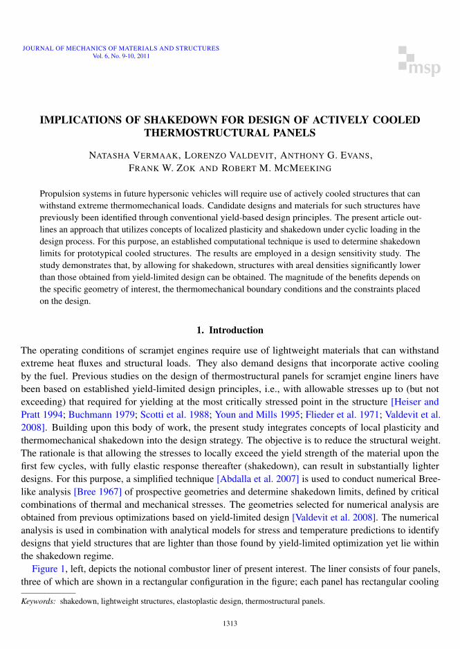
Figure 1, left, depicts the notional combustor liner of present interest. The liner consists of four panels,three of which are shown in a rectangular configuration in the figure; each panel has rectangular cooling
Keywords: shakedown, lightweight structures, elastoplastic design, thermostructural panels.
1313
1314 N. VERMAAK, L. VALDEVIT, A. G. EVANS, F. W. ZOK AND R. M. MCMEEKING
b
1
2
3
5
4
6
7
8
9
10
11
12
13
14
15
16
17
18
b
b
Design I
Design II
y
z x
(a)
(b)
b
1
2
3
5
4
6
7
8
9
10
11
12
13
14
15
16
17
18
b
b
Design I
Design II
y
z x
(a)
(b)
Figure 1. Left: notional design of scramjet engine liner. The two designs are distin-guished by the nature of the underlying structure: either periodic linear supports orcontinuous panel. Both are assumed to be connected to the liner via rollers, therebyallowing unconstrained lateral thermal expansion. Right: cross-section through the linerand the locations of the 18 points most susceptible to yielding and monitored in theoptimization code.
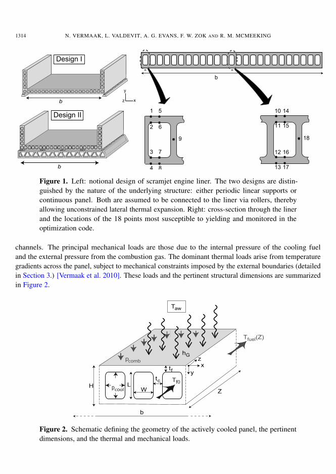
channels. The principal mechanical loads are those due to the internal pressure of the cooling fueland the external pressure from the combustion gas. The dominant thermal loads arise from temperaturegradients across the panel, subject to mechanical constraints imposed by the external boundaries (detailedin Section 3.) [Vermaak et al. 2010]. These loads and the pertinent structural dimensions are summarizedin Figure 2.
H
tfx
y
z
pcool
tcL
W
pcomb
Tf0
Tfuel(Z)
Taw
hG
Z
b
Figure 2. Schematic defining the geometry of the actively cooled panel, the pertinentdimensions, and the thermal and mechanical loads.
IMPLICATIONS OF SHAKEDOWN FOR DESIGN OF ACTIVELY COOLED THERMOSTRUCTURAL PANELS 1315
The article is organized as follows. First, the technique used to numerically determine shakedownlimits is presented. Next, the use of the technique in the construction of a Bree diagram for a proto-typical geometry is demonstrated. The results of a series of such computations are then used to identifyoptimal designs (with minimum mass) and their mass compared with those obtained through yield-limitedoptimizations. The weight benefits imparted by extending the design from yield-limited to shakedown-limited are computed for two types of external boundary conditions on the panel.
2. Construction of Bree diagrams
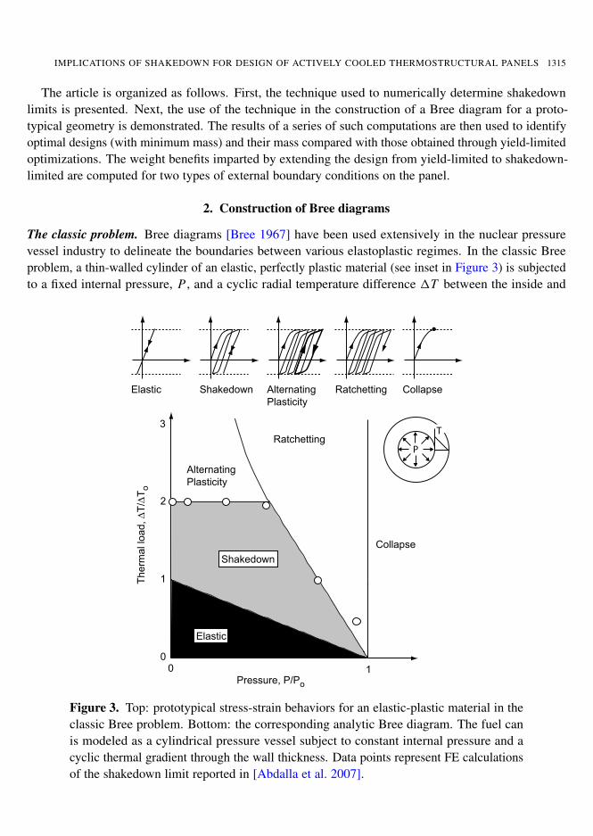
The classic problem. Bree diagrams [Bree 1967] have been used extensively in the nuclear pressurevessel industry to delineate the boundaries between various elastoplastic regimes. In the classic Breeproblem, a thin-walled cylinder of an elastic, perfectly plastic material (see inset in Figure 3) is subjectedto a fixed internal pressure, P , and a cyclic radial temperature difference 1T between the inside and
P
T
Elastic
Shakedown
1
2
3
00 1
AlternatingPlasticity
Pressure, P/Po
Ther
mal
load
, ∆T/
∆To
(b)
(a)
Ratchetting
Elastic Shakedown AlternatingPlasticity
Ratchetting Collapse
Collapse
P
T
Elastic
Shakedown
1
2
3
00 1
AlternatingPlasticity
Pressure, P/Po
Ther
mal
load
, ∆T/
∆To
(b)
(a)
Ratchetting
Elastic Shakedown AlternatingPlasticity
Ratchetting Collapse
Collapse
Figure 3. Top: prototypical stress-strain behaviors for an elastic-plastic material in theclassic Bree problem. Bottom: the corresponding analytic Bree diagram. The fuel canis modeled as a cylindrical pressure vessel subject to constant internal pressure and acyclic thermal gradient through the wall thickness. Data points represent FE calculationsof the shakedown limit reported in [Abdalla et al. 2007].
1316 N. VERMAAK, L. VALDEVIT, A. G. EVANS, F. W. ZOK AND R. M. MCMEEKING
outside walls.1 The resulting Bree diagram is shown in Figure 3, bottom. The ordinate is 1T/1T0,where 1T0 is the temperature difference required for yield initiation in the absence of a mechanical load;the abscissa is P/P0 with P0 being the pressure that causes yielding in the absence of a temperaturegradient.
For this configuration, the elastic domain is defined by P/P0+1T/1T0 < 1. At one extreme, whereP/P0 > 1, plastic collapse occurs on the first load cycle. For intermediate combinations of P and 1T ,one of three behaviors is obtained (Figure 3) [Abdel-Karim 2005].
(1) In the shakedown regime, localized plastic deformation that occurs in the early stages of cyclinggives rise to residual stresses that stabilize the plastic deformation. The consequence is purely elasticbehavior during further loading cycles.
(2) Alternating plasticity occurs by loading beyond the shakedown limit. Here the plastic strain incre-ment obtained during the first half of each loading cycle is followed by a plastic strain increment ofequal magnitude but opposite sign during the second half. No net strain accrues during each cyclebut the structure ultimately fails by low-cycle fatigue.
(3) Ratcheting refers to the condition in which a net increment of plastic strain accumulates during eachcycle, eventually causing plastic collapse.
Computational approach. Although Bree diagrams can be constructed for simple geometries and load-ing conditions using analytical models [Bree 1967], numerical techniques are generally required [Abdel-Karim 2005]. In the present study, finite element analysis (FEA) is used to apply a methodology initiallyreported in [Abdalla et al. 2007]. The approach yields an estimate of the shakedown limit in accordancewith Melan’s lower bound theorem2. The theorem states that a structure will shakedown if a time-independent residual stress field can be found which satisfies mechanical equilibrium and the boundaryconditions and the combined residual and elastic stresses do not exceed yield at any time during theloading cycle [König 1987; Bower 2009].
For implementation, the methodology requires two sets of computations for each geometry. In the first,the stresses caused by the cyclic load in an elastic structure are computed. This analysis is performedonly once and its output stored. The second is an elastic-plastic analysis, assuming perfectly plasticbehavior beyond yield, incorporating both the time-invariant and the cyclic loads in consecutive steps.The time-invariant load is applied first to a specified level and a half cycle of the varying load is thenapplied to its specified level. Each is incremented monotonically from zero to its peak value while anelastic-plastic analysis is carried out. Residual stresses are then calculated at every material point inaccordance with
σr,n = σEP,n − σE1Cn
1Cref, (1)
where σE and 1Cref are the stress tensor and cyclic load amplitude for the elastic analysis and σEP,n and1Cn are the corresponding values for the stress tensor and cyclic load amplitude resulting from the n-thtrial calculation in the elastic-plastic analysis [Abdalla et al. 2007]. If the effective (von Mises) residual
1Subsequently, the effects of alternative loading sequences (e.g., in-phase versus out-of-phase) were also investigated [Ngand Moreton 1983].
2The Melan theorem and all analyses presented herein assume elastic perfectly plastic material behavior.
IMPLICATIONS OF SHAKEDOWN FOR DESIGN OF ACTIVELY COOLED THERMOSTRUCTURAL PANELS 1317
stresses lie inside the yield surface at every point in the structure, the n-th combination of time-invariantand cyclic loads constitute a lower bound to the shakedown limit. The process is repeated for progres-sively increasing time-invariant and cyclic loads until yield is just reached by the resulting effectiveresidual stress. The associated combination of time-invariant and cyclic loads represents one point onthe shakedown curve on the Bree diagram. The computations are repeated for other load combinationsuntil the full shakedown boundary is obtained over the domain of interest. Results obtained in [Abdallaet al. 2007] for the classic Bree problem are reported in Figure 3.
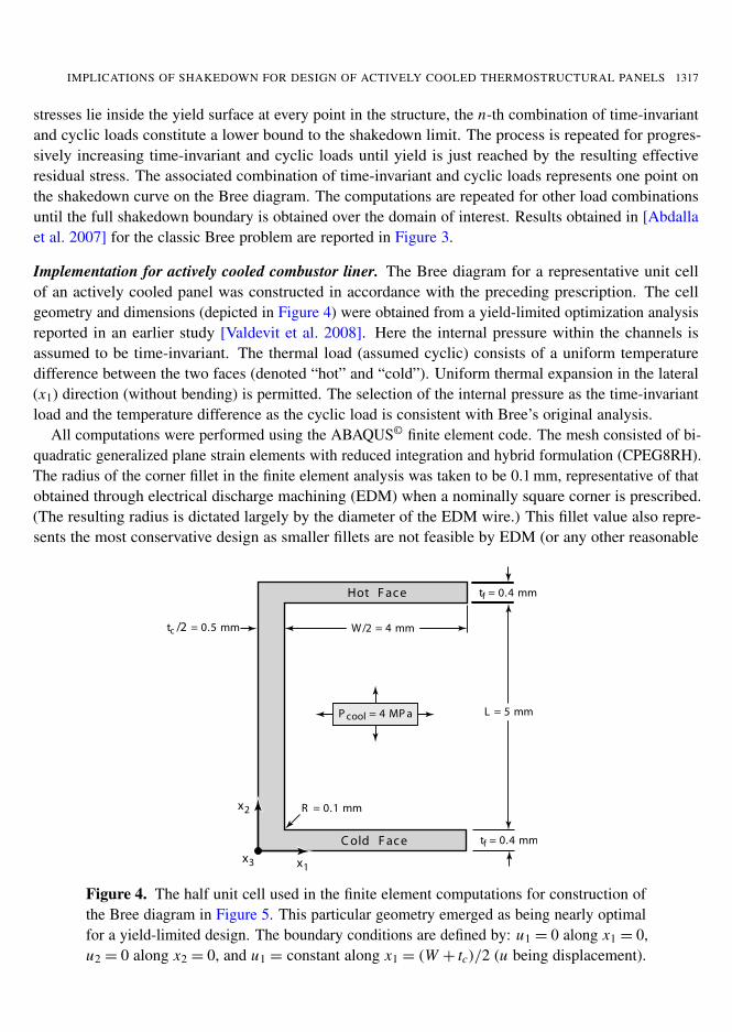
Implementation for actively cooled combustor liner. The Bree diagram for a representative unit cellof an actively cooled panel was constructed in accordance with the preceding prescription. The cellgeometry and dimensions (depicted in Figure 4) were obtained from a yield-limited optimization analysisreported in an earlier study [Valdevit et al. 2008]. Here the internal pressure within the channels isassumed to be time-invariant. The thermal load (assumed cyclic) consists of a uniform temperaturedifference between the two faces (denoted “hot” and “cold”). Uniform thermal expansion in the lateral(x1) direction (without bending) is permitted. The selection of the internal pressure as the time-invariantload and the temperature difference as the cyclic load is consistent with Bree’s original analysis.
All computations were performed using the ABAQUS© finite element code. The mesh consisted of bi-quadratic generalized plane strain elements with reduced integration and hybrid formulation (CPEG8RH).The radius of the corner fillet in the finite element analysis was taken to be 0.1 mm, representative of thatobtained through electrical discharge machining (EDM) when a nominally square corner is prescribed.(The resulting radius is dictated largely by the diameter of the EDM wire.) This fillet value also repre-sents the most conservative design as smaller fillets are not feasible by EDM (or any other reasonable
x2
x1x3
P cool = 4 MP a
Hot F ac e
C old F ac e
R = 0.1 mm
W/2 = 4 mm
L = 5 mm
tf = 0.4 mm
tf = 0.4 mm
tc /2 = 0.5 mm
Figure 4. The half unit cell used in the finite element computations for construction ofthe Bree diagram in Figure 5. This particular geometry emerged as being nearly optimalfor a yield-limited design. The boundary conditions are defined by: u1 = 0 along x1 = 0,u2 = 0 along x2 = 0, and u1 = constant along x1 = (W + tc)/2 (u being displacement).
1318 N. VERMAAK, L. VALDEVIT, A. G. EVANS, F. W. ZOK AND R. M. MCMEEKING
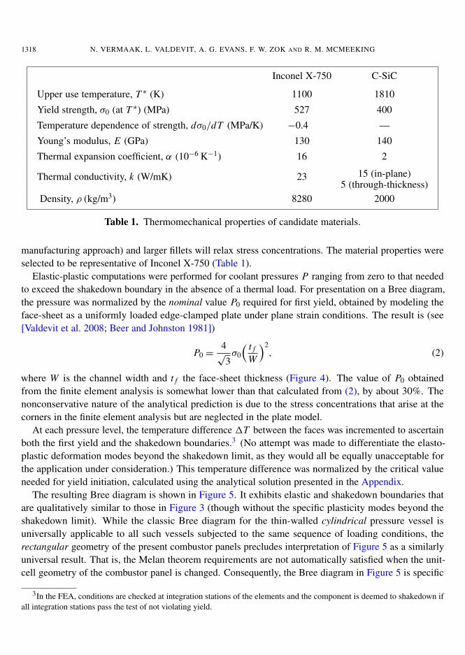
Inconel X-750 C-SiC
Upper use temperature, T ∗ (K) 1100 1810
Yield strength, σ0 (at T ∗) (MPa) 527 400
Temperature dependence of strength, dσ0/dT (MPa/K) −0.4 —
Young’s modulus, E (GPa) 130 140
Thermal expansion coefficient, α (10−6 K−1) 16 2
Thermal conductivity, k (W/mK) 23 15 (in-plane)5 (through-thickness)
Density, ρ (kg/m3) 8280 2000
Table 1. Thermomechanical properties of candidate materials.
manufacturing approach) and larger fillets will relax stress concentrations. The material properties wereselected to be representative of Inconel X-750 (Table 1).
Elastic-plastic computations were performed for coolant pressures P ranging from zero to that neededto exceed the shakedown boundary in the absence of a thermal load. For presentation on a Bree diagram,the pressure was normalized by the nominal value P0 required for first yield, obtained by modeling theface-sheet as a uniformly loaded edge-clamped plate under plane strain conditions. The result is (see[Valdevit et al. 2008; Beer and Johnston 1981])
P0 =4√
3σ0
( t f
W
)2, (2)
where W is the channel width and t f the face-sheet thickness (Figure 4). The value of P0 obtainedfrom the finite element analysis is somewhat lower than that calculated from (2), by about 30%. Thenonconservative nature of the analytical prediction is due to the stress concentrations that arise at thecorners in the finite element analysis but are neglected in the plate model.
At each pressure level, the temperature difference 1T between the faces was incremented to ascertainboth the first yield and the shakedown boundaries.3 (No attempt was made to differentiate the elasto-plastic deformation modes beyond the shakedown limit, as they would all be equally unacceptable forthe application under consideration.) This temperature difference was normalized by the critical valueneeded for yield initiation, calculated using the analytical solution presented in the Appendix.
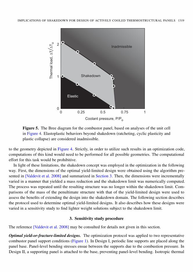
The resulting Bree diagram is shown in Figure 5. It exhibits elastic and shakedown boundaries thatare qualitatively similar to those in Figure 3 (though without the specific plasticity modes beyond theshakedown limit). While the classic Bree diagram for the thin-walled cylindrical pressure vessel isuniversally applicable to all such vessels subjected to the same sequence of loading conditions, therectangular geometry of the present combustor panels precludes interpretation of Figure 5 as a similarlyuniversal result. That is, the Melan theorem requirements are not automatically satisfied when the unit-cell geometry of the combustor panel is changed. Consequently, the Bree diagram in Figure 5 is specific
3In the FEA, conditions are checked at integration stations of the elements and the component is deemed to shakedown ifall integration stations pass the test of not violating yield.
IMPLICATIONS OF SHAKEDOWN FOR DESIGN OF ACTIVELY COOLED THERMOSTRUCTURAL PANELS 1319
2
1
00 0.5 1
Coolant pressure, P/Po
Elastic
Shakedown
0.25 0.75
Inadmissible∆To
Ther
mal
load
,∆T
Figure 5. The Bree diagram for the combustor panel, based on analyses of the unit cellin Figure 4. Elastoplastic behaviors beyond shakedown (ratcheting, cyclic plasticity andplastic collapse) are considered inadmissible.
to the geometry depicted in Figure 4. Strictly, in order to utilize such results in an optimization code,computations of this kind would need to be performed for all possible geometries. The computationaleffort for this task would be prohibitive.
In light of these limitations, the shakedown concept was employed in the optimization in the followingway. First, the dimensions of the optimal yield-limited design were obtained using the algorithm pre-sented in [Valdevit et al. 2008] and summarized in Section 3. Then, the dimensions were incrementallyvaried in a manner that yielded a mass reduction and the shakedown limit was numerically computed.The process was repeated until the resulting structure was no longer within the shakedown limit. Com-parisons of the mass of the penultimate structure with that of the yield-limited design were used toassess the benefits of extending the design into the shakedown domain. The following section describesthe protocol used to determine optimal yield-limited designs. It also describes how these designs werevaried in a sensitivity study to find lighter weight solutions subject to the shakedown limit.
3. Sensitivity study procedure
The reference [Valdevit et al. 2008] may be consulted for details not given in this section.
Optimal yield-or-fracture-limited designs. The optimization protocol was applied to two representativecombustor panel support conditions (Figure 1). In Design I, periodic line supports are placed along thepanel base. Panel-level bending stresses ensue between the supports due to the combustion pressure. InDesign II, a supporting panel is attached to the base, preventing panel-level bending. Isotropic thermal
1320 N. VERMAAK, L. VALDEVIT, A. G. EVANS, F. W. ZOK AND R. M. MCMEEKING
expansion is permitted in both designs. The essential difference between the designs is that, in Design II,the combustion pressure is rendered inconsequential, reducing the dominant loads to two: the coolantpressure and the panel level thermal gradient. In contrast, three loads remain for Design I.
The optimization protocol consists of the following steps. The values of heat load and fuel flow rateare identified for the specified vehicle Mach number, assumed to be 7. The heat load is characterizedby the temperature difference between the combustion gas (specifically, the adiabatic wall temperature,Taw = 3050 K) and the hot surface (evaluated analytically) and the corresponding heat transfer coefficient,hG . The latter was computed assuming steady-state combustion conditions, yielding hG = 445 W/m2K.The fuel flow rate through the cooling channels was taken to be that for stoichiometric combustion of thefuel with the available oxygen in the flowpath. The (internal) pressure in the cooling channels is set byinjection requirements (pcool = 4 MPa for a prototypical vehicle), and the (external) combustion chamberpressure is obtained by the flow conditions in the combustor (pcomb = 0.16 MPa for Mach 7 conditions).The design parameters are incrementally varied over a prescribed range and the pertinent stresses andtemperatures were computed. (In principle, the heat transfer coefficient can be increased to reflect localheat spikes due to nonuniform combustion and the flow rate varied relative to the stoichiometric value.Variations in these parameters were not considered in the present study.)
Temperature distributions were obtained by means of a thermal network model. The stresses due toboth the coolant pressure and the temperature gradients were obtained at critical locations using stan-dard thermoelastic plate analysis. A synopsis of the models for the temperature and stress distributionsis presented in the Appendix. Upon comparison of the computed stresses and temperatures with thecorresponding material and coolant properties, the viability of the design is ascertained.
Specifically, for viability in the case of metallic candidates that are yield-limited, the effective (vonMises) stress must not exceed the yield stress anywhere in the structure. Similarly, for ceramic matrixcomposite (CMC) candidates such as C/SiC, fracture-limited design is determined by ensuring that themaximum and minimum principal stresses in the structure remain below/above critical values (±400 MPafor C/SiC).
Additionally, for all candidates the fuel temperature must not exceed that for coking (975 K for JP-7)and the maximum material temperature must not exceed its upper use (softening) temperature (1100 Kfor Inconel X-750). If solutions exist, the design is optimized for minimum mass, Additionally, toensure realistic designs, constraints based on panel manufacturability and fuel pressure drop were alsoprescribed. For instance, to enable manufacturing of the panels by conventional means, minimum valueswere prescribed for the face and core member thicknesses (0.4 mm), the channel height (5 mm) and thechannel width (2 mm). Numerical optimizations were performed using the quadratic optimizer MINCONin MATLAB. The process was repeated using several different randomly generated initial guesses toensure the optimized solutions were not in local minima.
Probing benefits of shakedown. Two slightly different schemes were employed to calculate the opera-tional conditions associated with the two sets of boundary conditions (defined by Designs I and II) andassess whether they reside within the shakedown limit. The scheme for Design II is straightforward.The internal pressure is selected to be 4 MPa and the operational temperature difference, 1Tpanel, iscalculated from the thermal network model (Appendix). Comparisons of 1Tpanel with the shakedownvalue (calculated by FEA) determine the viability of the structure.
IMPLICATIONS OF SHAKEDOWN FOR DESIGN OF ACTIVELY COOLED THERMOSTRUCTURAL PANELS 1321
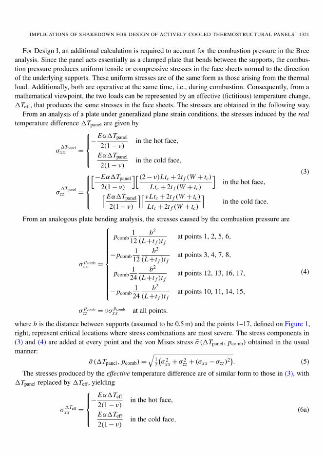
For Design I, an additional calculation is required to account for the combustion pressure in the Breeanalysis. Since the panel acts essentially as a clamped plate that bends between the supports, the combus-tion pressure produces uniform tensile or compressive stresses in the face sheets normal to the directionof the underlying supports. These uniform stresses are of the same form as those arising from the thermalload. Additionally, both are operative at the same time, i.e., during combustion. Consequently, from amathematical viewpoint, the two loads can be represented by an effective (fictitious) temperature change,1Teff, that produces the same stresses in the face sheets. The stresses are obtained in the following way.
From an analysis of a plate under generalized plane strain conditions, the stresses induced by the realtemperature difference 1Tpanel are given by
σ1Tpanelxx =
−
Eα1Tpanel
2(1− ν)in the hot face,
Eα1Tpanel
2(1− ν)in the cold face,
σ1Tpanelzz =
[−Eα1Tpanel
2(1− ν)
][(2− ν)Ltc+ 2t f (W + tc)Ltc+ 2t f (W + tc)
]in the hot face,[Eα1Tpanel
2(1− ν)
][νLtc+ 2t f (W + tc)Ltc+ 2t f (W + tc)
]in the cold face.
(3)
From an analogous plate bending analysis, the stresses caused by the combustion pressure are
σ pcombxx =
pcomb1
12b2
(L+t f )t fat points 1, 2, 5, 6,
−pcomb112
b2
(L+t f )t fat points 3, 4, 7, 8,
pcomb1
24b2
(L+t f )t fat points 12, 13, 16, 17,
−pcomb124
b2
(L+t f )t fat points 10, 11, 14, 15,
σ pcombzz = νσ pcomb
xx at all points.
(4)
where b is the distance between supports (assumed to be 0.5 m) and the points 1–17, defined on Figure 1,right, represent critical locations where stress combinations are most severe. The stress components in(3) and (4) are added at every point and the von Mises stress σ̄ (1Tpanel, pcomb) obtained in the usualmanner:
σ̄ (1Tpanel, pcomb)=
√12
(σ 2
xx + σ2zz + (σxx − σzz)2
). (5)
The stresses produced by the effective temperature difference are of similar form to those in (3), with1Tpanel replaced by 1Teff, yielding
σ1Teffxx =
−
Eα1Teff
2(1− ν)in the hot face,
Eα1Teff
2(1− ν)in the cold face,
(6a)
1322 N. VERMAAK, L. VALDEVIT, A. G. EVANS, F. W. ZOK AND R. M. MCMEEKING
σ1Teffzz =
[−Eα1Teff
2(1− ν)
][(2− ν)Ltc+ 2t f (W + tc)Ltc+ 2t f (W + tc)
]in the hot face,[Eα1Teff
2(1− ν)
][νLtc+ 2t f (W + tc)Ltc+ 2t f (W + tc)
]in the cold face.
(6b)
The corresponding effective stress is
σ̄ (1Teff)=
√12
[(σ1Teffxx
)2+ (σ
1Teffzz )2+ (σ
1Teffxx − σ
1Teffzz )2
]. (7)
The effective temperature difference is obtained by setting σ̄ (1Tpanel, pcomb) = σ̄ (1Teff)— see Equa-tions (5) and (7) — and numerically inverting the result to obtain 1Teff(1Tpanel, pcomb). The viability ofa design is ascertained by comparing 1Teff with the shakedown limit computed by FEA.
4. Designs allowing shakedown
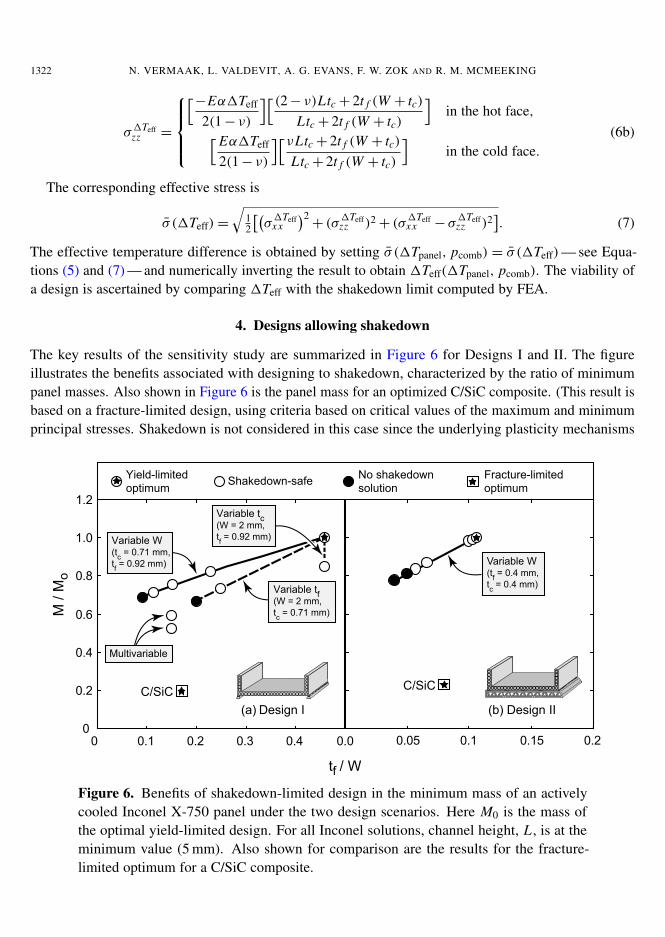
The key results of the sensitivity study are summarized in Figure 6 for Designs I and II. The figureillustrates the benefits associated with designing to shakedown, characterized by the ratio of minimumpanel masses. Also shown in Figure 6 is the panel mass for an optimized C/SiC composite. (This result isbased on a fracture-limited design, using criteria based on critical values of the maximum and minimumprincipal stresses. Shakedown is not considered in this case since the underlying plasticity mechanisms
0.05 0.1 0.15 0.2
(b)0
0.2
0.4
0.6
0.8
1.0
1.2
0 0.1 0.2 0.3 0.4 0.0
tf / W
M /
Mo
Variable W(tf = 0.4 mm,tc = 0.4 mm)
C/SiC
Variable tf(W = 2 mm,tc = 0.71 mm)
Multivariable
Variable tc(W = 2 mm,tf = 0.92 mm)Variable W
(tc = 0.71 mm,tf = 0.92 mm)
C/SiC
Yield-limitedoptimum
(a) Design I Design II
Shakedown-safe No shakedownsolution
Fracture-limitedoptimum
Figure 6. Benefits of shakedown-limited design in the minimum mass of an activelycooled Inconel X-750 panel under the two design scenarios. Here M0 is the mass ofthe optimal yield-limited design. For all Inconel solutions, channel height, L , is at theminimum value (5 mm). Also shown for comparison are the results for the fracture-limited optimum for a C/SiC composite.
IMPLICATIONS OF SHAKEDOWN FOR DESIGN OF ACTIVELY COOLED THERMOSTRUCTURAL PANELS 1323
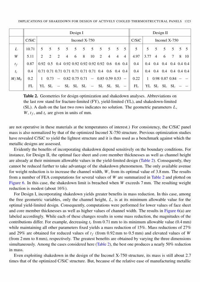
Design I Design II
C/SiC Inconel X-750 C/SiC Inconel X-750
L 10.71 5 5 5 5 5 5 5 5 5 5 5 5 5 5 5 5 5 5
W 5.11 2 2 2 4 6 8 10 2 4 4 4 4.97 3.77 4 6 7 8 10
t f 0.87 0.92 0.5 0.4 0.92 0.92 0.92 0.92 0.92 0.6 0.6 0.4 0.4 0.4 0.4 0.4 0.4 0.4 0.4
tc 0.4 0.71 0.71 0.71 0.71 0.71 0.71 0.71 0.4 0.6 0.4 0.4 0.4 0.4 0.4 0.4 0.4 0.4 0.4
M/M0 0.2 1 0.73 − 0.82 0.75 0.71 − 0.85 0.59 0.53 − 0.22 1 0.98 0.87 0.84 − −
FL YL SL − SL SL SL − SL SL SL − FL YL SL SL SL − −
Table 2. Geometries for design optimization and shakedown analyses. Abbreviations onthe last row stand for fracture-limited (FY), yield-limited (YL), and shakedown-limited(SL). A dash on the last two rows indicates no solution. The geometric parameters L ,W , t f , and tc are given in units of mm.
are not operative in these materials at the temperatures of interest.) For consistency, the C/SiC panelmass is also normalized by that of the optimized Inconel X-750 structure. Previous optimization studieshave revealed C/SiC to yield the lightest structure and it is thus used as a benchmark against which themetallic designs are assessed.
Evidently the benefits of incorporating shakedown depend sensitively on the boundary conditions. Forinstance, for Design II, the optimal face sheet and core member thicknesses as well as channel heightare already at their minimum allowable values in the yield-limited design (Table 2). Consequently, theycannot be reduced further to take advantage of the shakedown phenomenon. The only available avenuefor weight reduction is to increase the channel width, W , from its optimal value of 3.8 mm. The resultsfrom a number of FEA computations for several values of W are summarized in Table 2 and plotted onFigure 6. In this case, the shakedown limit is breached when W exceeds 7 mm. The resulting weightreduction is modest (about 16%).
For Design I, incorporating shakedown yields greater benefits in mass reduction. In this case, amongthe free geometric variables, only the channel height, L , is at its minimum allowable value for theoptimal yield-limited design. Consequently, computations were performed for lower values of face sheetand core member thicknesses as well as higher values of channel width. The results in Figure 6(a) arelabeled accordingly. While each of these changes results in some mass reduction, the magnitudes of thecontributions differ. For example, decreasing tc from 0.71 mm to its minimum allowable value (0.4 mm)while maintaining all other parameters fixed yields a mass reduction of 15%. Mass reductions of 27%and 29% are obtained for reduced values of t f (from 0.92 mm to 0.5 mm) and elevated values of W(from 2 mm to 8 mm), respectively. The greatest benefits are obtained by varying the three dimensionssimultaneously. Among the cases considered here (Table 2), the best one produces a nearly 50% reductionin mass.
Even exploiting shakedown in the design of the Inconel X-750 structure, its mass is still about 2.7times that of the optimized C/SiC structure. But, because of the relative ease of manufacturing metallic
1324 N. VERMAAK, L. VALDEVIT, A. G. EVANS, F. W. ZOK AND R. M. MCMEEKING
components along with their superior structural robustness, the metallic alloy may prove to be preferableto the ceramic composite for the present application.
While the present shakedown analysis demonstrates potential weight savings, additional research isrequired to provide more insight into the physical behavior of such structures. Particularly, their responsein competition with creep environments is of interest. The computational approach presented providesa working limit for shakedown that motivates the development of complementary models of materialbehavior during structural shakedown.
5. Conclusions
Incorporating shakedown into the design of actively cooled thermostructural panels can enable significantweight reduction. The magnitude of the benefit depends on the component of interest, the boundaryconditions and the specific constraints placed on the design. For the component considered here — a linerfor a scramjet engine operating at stoichiometric fuel flow rates under steady-state combustion conditionsfor Mach 7 flight — significant benefits accrue only when the liner is weakly supported by an externalstructure. Otherwise, when the support structure provides a more substantial constraint on deformation,the design is influenced more heavily by the material softening temperature and the secondary constraintsderived from manufacturing limitations than by the thermomechanical loads. In such cases, the moreaggressive design strategy, exploiting shakedown, is of minimal benefit.
Appendix: Synopsis of analytical models
Temperature distributions. Analytical expressions for the temperatures at critical locations in the panelhave been obtained via a thermal network approach, subject to four simplifying assumptions:
(1) Taw and hG are uniform along the hot face;
(2) all heat is removed by forced convection in the cooling channels;
(3) longitudinal panel conduction is negligible so that the gradient of hot surface temperature in the fuelflow direction is due only to cooling into the fuel channel; and
(4) the coolant temperature, due to turbulent mixing, is uniform across the channel cross-section.
Based on the thermal network in Figure 7, the temperature in the fluid is:
T f = Taw− (Taw− T 0f ) · exp(−βz) (A.1)
and the temperature distributions at the 18 locations depicted in Figure 1 are:
T (i)= Taw− (Taw− T 0
f ) · F(i) exp(−βz) (A.2)
where F (i) and β depend on: the geometry of the panel (W, L , t f , tc); the thermal conductivity ofthe material, ks ; the thermal conductivity, k f , kinematic viscosity, ν f , and volumetric specific heat,ρ f cp, f , of the fuel; the heat transfer coefficient on the hot side, hG ; and the volumetric fuel flow rate, V̇(see [Valdevit et al. 2008] for details). Importantly, these functional dependencies are intertwined, thusprecluding straightforward interpretation of the effect of each quantity on the temperature distribution.
IMPLICATIONS OF SHAKEDOWN FOR DESIGN OF ACTIVELY COOLED THERMOSTRUCTURAL PANELS 1325
RG =1
hG tc
RG
w tc
WRG
RT B C
tT B C
kT B C tc
RT B C
w tc
WRT B C
R face
t f
ks tc
R face
w tc
WR face
Rcool
1
hc W
OVER THE WEB
BETWEEN WEBS
Qc(z)/2Qw(z)
Qw(z)+2 Qh(z)
Qh(z)
Rh
Rcool 2 Rfin
Rface
planes of symmetry
2 RG
2 RTBCRTBCw
RGw
Q(z) Taw
TBC
Qc(z)/2-Qh(z)
Tfuel(z) Tfuel(z)
R fin
tanh 1 2hc kstc L
2hc kstc kstc
Qc(z)/2
Qh(z)
2 Rfin
Rface
2 RG
2 RTBC
Tfuel(z)
Ttfw(z)
Qc(z)/2-Qh(z)
Rh
W tc / 2
4 kst f
Ttfc(z) RfaceRface Rface
w / 2
Rfacew / 2
= = =
=
====
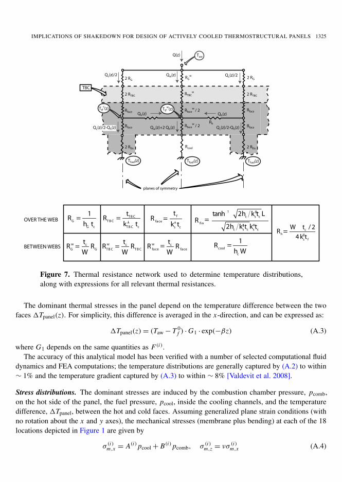
Figure 7. Thermal resistance network used to determine temperature distributions,along with expressions for all relevant thermal resistances.
The dominant thermal stresses in the panel depend on the temperature difference between the twofaces 1Tpanel(z). For simplicity, this difference is averaged in the x-direction, and can be expressed as:
1Tpanel(z)= (Taw− T 0f ) ·G1 · exp(−βz) (A.3)
where G1 depends on the same quantities as F (i).The accuracy of this analytical model has been verified with a number of selected computational fluid
dynamics and FEA computations; the temperature distributions are generally captured by (A.2) to within∼ 1% and the temperature gradient captured by (A.3) to within ∼ 8% [Valdevit et al. 2008].
Stress distributions. The dominant stresses are induced by the combustion chamber pressure, pcomb,on the hot side of the panel, the fuel pressure, pcool, inside the cooling channels, and the temperaturedifference, 1Tpanel, between the hot and cold faces. Assuming generalized plane strain conditions (withno rotation about the x and y axes), the mechanical stresses (membrane plus bending) at each of the 18locations depicted in Figure 1 are given by
σ (i)m,x = A(i) pcool+ B(i) pcomb, σ (i)m,z = νσ(i)m,x (A.4)
1326 N. VERMAAK, L. VALDEVIT, A. G. EVANS, F. W. ZOK AND R. M. MCMEEKING
where the functions A(i), B(i) depend on panel geometry and support conditions and ν is Poisson’s ratio.Similarly, the dominant thermal stresses can be expressed as:
σ(i)T,x =
Eα1− ν
(D(i)x 1T (i)
panel), σ(i)T,z =
Eα1− ν
(D(i)z 1T (i)
panel), (A.5)
where E and α are the Young’s modulus and the coefficient of thermal expansion, respectively. Thequantities D(i)
x and D(i)z are functions of geometry only. Additional details are presented in [Valdevit
et al. 2008]. The accuracy of this model has been verified with FEA. Its accuracy is better than ∼ 10%on the top face and ∼ 20% on the bottom face (loc. cit.).
Acknowledgements
This work was supported by the Office of Naval Research through the Multidisciplinary University Re-search Initiative program on Revolutionary Materials for Hypersonic Flight (Contract N00014-05-1-0439,Program Manager Dr. J. Christodoulou). Computing time on a HP Opteron cluster was provided by theCalifornia NanoSystems Institute at the University of California, Santa Barbara and by Hewlett-Packard.Helpful correspondence with and advice from Dr. H. F. Abdalla of The American University in Cairo isgreatly appreciated.
References
[Abdalla et al. 2007] H. F. Abdalla, M. M. Megahed, and M. Y. A. Younan, “A simplified technique for shakedown limit loaddetermination”, Nucl. Eng. Des. 237:12–13 (2007), 1231–1240.
[Abdel-Karim 2005] M. Abdel-Karim, “Shakedown of complex structures according to various hardening rules”, Int. J. Press.Vessels Pip. 82:6 (2005), 427–458.
[Beer and Johnston 1981] F. P. Beer and E. R. Johnston, Mechanics of materials, Chapter 7, McGraw-Hill, New York, 1981.
[Bower 2009] A. F. Bower, Applied mechanics of solids, Chapter 6, pp. 381–422, CRC Press, Boca Raton, FL, 2009, Availableat http://www.solidmechanics.org.
[Bree 1967] J. Bree, “Elastic-plastic behaviour of thin tubes subjected to internal pressure and intermittent high-heat fluxeswith application to fast-nuclear-reactor fuel elements”, J. Strain Anal. Eng. Des. 2:3 (1967), 226–238.
[Buchmann 1979] O. A. Buchmann, “Thermal-structural design study of an airframe-integrated scramjet”, Contractor reportNASA CR-3141, NASA, Washington, DC, 1979, Available at http://www.tinyurl.com/NASA-CR-3141.
[Flieder et al. 1971] W. C. Flieder, C. E. Richard, O. A. Buchmann, and F. M. Walters, “An analytical study of hydrogen cooledpanels for application to hypersonic aircraft”, Contractor report NASA CR-1650, NASA, Washington, DC, 1971, Available athttp://www.tinyurl.com/NASA-CR-1650.
[Heiser and Pratt 1994] W. H. Heiser and D. T. Pratt, Hypersonic airbreathing propulsion, AIAA, Washington, DC, 1994.
[König 1987] J. A. König, Shakedown of elastic-plastic structures, Chapter 4, Fundamental Studies in Engineering 7, Elsevier,Amsterdam, 1987.
[Ng and Moreton 1983] H. W. Ng and D. N. Moreton, “Bree diagrams for alternative loading sequences”, pp. 279–312 inEngineering approaches to high temperature design, edited by B. Wilshire and D. R. J. Owen, Recent Advances in Creep andFracture of Engineering Materials and Structures 2, Pineridge Press, Swansea, 1983.
[Scotti et al. 1988] S. J. Scotti, C. J. Martin, and S. H. Lucas, “Active cooling design for scramjet engines using optimizationmethods”, Technical memorandum NASA TM-100581, NASA Langley Research Center, Hampton, VA, 1988, Available athttp://www.tinyurl.com/NASA-TM-100581.
[Valdevit et al. 2008] L. Valdevit, N. Vermaak, F. W. Zok, and A. G. Evans, “A materials selection protocol for lightweightactively cooled panels”, J. Appl. Mech. (ASME) 75:6 (2008), 061022.
IMPLICATIONS OF SHAKEDOWN FOR DESIGN OF ACTIVELY COOLED THERMOSTRUCTURAL PANELS 1327
[Vermaak et al. 2010] N. Vermaak, L. Valdevit, and A. G. Evans, “Influence of configuration on materials selection for activelycooled combustors”, J. Propuls. Power 26:2 (2010), 295–302.
[Youn and Mills 1995] B. Youn and A. F. Mills, “Cooling panel optimization for the active cooling system of a hypersonicaircraft”, J. Thermophys. Heat Transf. 9:1 (1995), 136–143.
Received 24 May 2011. Revised 28 Jul 2011. Accepted 8 Aug 2011.
NATASHA VERMAAK: [email protected] Department, University of California, Santa Barbara, CA 93106-5050, United States
LORENZO VALDEVIT: [email protected] of Mechanical and Aerospace Engineering and Department of Chemical Engineering and Materials Science,University of California, Irvine, CA 92697-3975, United States
ANTHONY G. EVANS: [email protected] Department, University of California, Santa Barbara, CA 93106-5050, United Stateshttp://www.me.ucsb.edu/dept_site/people/evans_page.html
FRANK W. ZOK: [email protected] Department, University of California, Santa Barbara, CA 93106-5050, United Stateshttp://engineering.ucsb.edu/~zok/zok.html
ROBERT M. MCMEEKING: [email protected] and Mechanical Engineering Departments, University of California, Santa Barbara, CA 93106-5050, United States
mathematical sciences publishers msp
JOURNAL OF MECHANICS OF MATERIALS AND STRUCTURESjomms.org
Founded by Charles R. Steele and Marie-Louise Steele
EDITORS
CHARLES R. STEELE Stanford University, USADAVIDE BIGONI University of Trento, ItalyIWONA JASIUK University of Illinois at Urbana-Champaign, USA
YASUHIDE SHINDO Tohoku University, Japan
EDITORIAL BOARD
H. D. BUI École Polytechnique, FranceJ. P. CARTER University of Sydney, Australia
R. M. CHRISTENSEN Stanford University, USAG. M. L. GLADWELL University of Waterloo, Canada
D. H. HODGES Georgia Institute of Technology, USAJ. HUTCHINSON Harvard University, USA
C. HWU National Cheng Kung University, TaiwanB. L. KARIHALOO University of Wales, UK
Y. Y. KIM Seoul National University, Republic of KoreaZ. MROZ Academy of Science, Poland
D. PAMPLONA Universidade Católica do Rio de Janeiro, BrazilM. B. RUBIN Technion, Haifa, Israel
A. N. SHUPIKOV Ukrainian Academy of Sciences, UkraineT. TARNAI University Budapest, Hungary
F. Y. M. WAN University of California, Irvine, USAP. WRIGGERS Universität Hannover, Germany
W. YANG Tsinghua University, ChinaF. ZIEGLER Technische Universität Wien, Austria
PRODUCTION [email protected]
SILVIO LEVY Scientific Editor
Cover design: Alex Scorpan Cover photo: Mando Gomez, www.mandolux.com
See http://jomms.org for submission guidelines.
JoMMS (ISSN 1559-3959) is published in 10 issues a year. The subscription price for 2011 is US $520/year for the electronicversion, and $690/year (+$60 shipping outside the US) for print and electronic. Subscriptions, requests for back issues, and changesof address should be sent to Mathematical Sciences Publishers, Department of Mathematics, University of California, Berkeley,CA 94720–3840.
JoMMS peer-review and production is managed by EditFLOW® from Mathematical Sciences Publishers.
PUBLISHED BYmathematical sciences publishers
http://msp.org/
A NON-PROFIT CORPORATIONTypeset in LATEX
Copyright ©2011 by Mathematical Sciences Publishers
Journal of Mechanics of Materials and StructuresVolume 6, No. 9-10 November–December 2011
Turtle shell and mammal skull resistance to fracture due to predator bites andground impact DAVID L. HU, KELLY SIELERT and MICHAEL GORDON 1197
Linear buckling analysis of cracked plates by SFEM and XFEM P. M. BAIZ,S. NATARAJAN, S. P. A. BORDAS, P. KERFRIDEN and T. RABCZUK 1213
A finite element for form-finding and static analysis of tensegrity structuresDARIO GASPARINI, KATALIN K. KLINKA and VINICIUS F. ARCARO 1239
Structural design of pyramidal truss core sandwich beams loaded in 3-pointbending MING LI, LINZHI WU, LI MA, BING WANG and ZHENGXI GUAN 1255
Wave scattering from a rectangular crack in an anisotropic claddingPER-ÅKE JANSSON 1267
Effect of adding crumb tire rubber particles on the mechanical properties ofDCPD-modified sulfur polymer mortarsHAMED MARAGHECHI, IMAN FOTOVAT AHMADI and SIAMAK MOTAHARI 1283
Uniqueness theorems in the equilibrium theory of thermoelasticity withmicrotemperatures for microstretch solids
ANTONIO SCALIA and MERAB SVANADZE 1295Implications of shakedown for design of actively cooled thermostructural panels
NATASHA VERMAAK, LORENZO VALDEVIT, ANTHONY G. EVANS,FRANK W. ZOK and ROBERT M. MCMEEKING 1313
JournalofMechanics
ofMaterials
andStructures
2011V
ol.6,No.9-10