Embed Size (px)
Citation preview

Mechanism of Solid State Pressure Welding
Study establishes a rational basis for atom-to-atom bonding that supports neither the film theory nor the diffusion principle
BY H. A. MOHAMED AND J. WASHBURN
ABSTRACT. The mechanism of pressure welding in polycrystalline aluminum, copper, silver and gold was investigated. The role of the oxide fi lm was studied and it was found that no metal to oxide bonding contributes to the strength of the weld. From scanning electron microscope observations a two-stage model has been suggested which could explain the dif ferent behavior of the metals studied.
The first stage of welding involves the formation of overlapped oxide-free metallic areas; this is controlled by: (a) difference on a microscale of the local plastic strain occurring on matching opposite faces of the weld interface, (b) relative hardness of the metal and its oxide fi lm, and (c) mechanical properties of the oxide.
The second stage involves: (a) plastic flow of the metal to the overlapped areas; the stress at which this can take place is influenced by the stacking fault energy of the metal, and (b) some relative shear displacement at the points where metal cleaned of oxide comes into contact; this is influenced by surface roughness.
The different weldability of different metals is attributed to differences in stacking fault energy, hardness ratio and plastic properties of the oxide. The weld strength calculated theoretically on the basis of measured
The authors are associated with the Inorganic Materials Research Division. Lawrence Berkeley Laboratory and the Department of Materials Science and Engineering, College of Engineering, respectively, at the University of California, Berkeley, California 94720.
welded area was in agreement with measured fracture strength. It was concluded that the strength attained after a given deformation is determined by the fractional welded area at that deformation.
Introduction Pressure welding is the establish
ment of an atom-to-atom bond between the two pieces to be joined through intimate contact between oxide- f ree areas achieved under pressure and without the formation of liquid phase.
In order to develop this bond, surface films have to be removed or at least reduced in amount. Surface fi lms fall into two categories:
Oxide Film
All metals except gold possess an oxide film at room temperature. In most metals the oxide film reaches a limiting thickness in the range 20-100 angs t roms at room t e m p e r a t u r e (Ref. 1).
Contaminant Film
This film consists of a thin layer of moisture and greases. The best technique which has proved (Refs. 2-4) to be successful in reducing these films is a combination of chemical and mechanical cleaning.
Two theories have been proposed so far to explain the mechanism of pressure welding:
The Film Theory
This theory (Refs. 2, 5) proposes that if two clean metal surfaces are
brought into intimate contact a weld will be created. The theory attributes the different weldability of different metals to the relative hardness of the bulk metal and oxide. Initiation of welding is controlled by the degree of fragmentation of the oxide fi lm.
In the present work, scanning electron microscope photographs show that oxide films on aluminum, copper and silver crack at deformat ions much less than the minimum welding deformation (see Fig. 1); the way this deformation was determined will be discussed.
This suggests that it is not only the fragmentation of the oxide film which controls the initiation of welding.
Energy Barrier Theory
The energy barrier theory (Refs. 6, 7) suggests that even if clean surfaces are brought into contact no weld will result. The theory states that an energy barrier exists that must be overcome before welding can take place. Parks (Ref. 7) thought that the barrier is recrystallization while Erd-mann-Jesnitzer (Ref. 6) thought that it is diffusion. Semenov (Ref. 6) suggested that the energy barrier comes from the misorientation of the crystals at the contact surface, since he could weld aluminum, copper and silver at the temperature of liquid nitrogen. It is impossible to assume that welding at this temperature occurred due to diffusion or recrystallization.
McEwen and Milner (Ref. 8) have shown that immiscible metal pairs can be joined satisfactorily.
In the present work the rate of applying the pressure was found to have
302-s I S E P T E M B E R 1 9 7 5

no effect on either the welding deformation or the weld strength. It will be shown that the misorientation factor has an important effect in the initiation of welding.
Experimental Procedure
Materials
Materials for Lap Welding. The materials used for this study in-
-" / %i
i T t ^ X t i r '
eluded high purity aluminum, silver, copper, gold (purity, 99.999%) and commercial purity aluminum (purity, 99%). The dimensions of the strips were 75 mm length, 18.75 mm width and the thickness ranged from 0.8 to 1.2 mm. The overlapping distance was 25 mm.
Materials for Butt Welding. These materials included high purity aluminum (purity. 99.995%) and 6061T6 aluminum alloy (main alloying elements are silicon and magnesium). The dimensions of the rods were 60 mm length and 9 mm diameter.
Procedure
Welding Dies. Two welding dies were designed, one for lap welding and the other for butt welding. Figure 2 is a schematic illustration of these dies.
Surface Preparation. In order to reduce surface fi lms, all the specimens were first degreased in acetone and then wire brushed using a motor driven wire brush. Figure 3 shows a scanning electron microscope photograph for an aluminum surface. It is seen that the surface consists of a series of hills and valleys.
Welding. After surface preparat ion, the specimens were immediately set in the welding die and then the pressure was applied. At the beginning of the experiments, the pressure was applied at very slow rate and then at a much higher rate. It was
lOOmm -* — 5 0 m m
l - T - r H
Specimen
i 20mm I30rr
r—L-J—I _ i _
45 mm
t
- 35mm -4 5 mm - - . -
(o) Butt Welding Die
- 40mm
• ' 3000X
Fig. 1 — Scanning photographs for the surfaces of aluminum, copper and silver of deformations below the minimum lap welding deformation. High purity aluminum: (A) 3% deformation, (B) 6% deformation. High purity copper: (C) 5% deformation, (D) 23% deformation. High purity silver: (E) 25% deformation. All reduced 9%
4 mm >-25mm
(b) Lop Welding Die
Fig. 2 — Schematic illustration of the welding dies
W E L D I N G R E S E A R C H S U P P L E M E N T ! 303-s

11000X Fig. 3 — Scanning photograph for aluminum surface after wire brushing. Reduced 41%
found that the rate of applying the pressure does not have a marked effect on either the welding deformation or the weld strength. The welding time (time of applying and releasing the pressure) was then set to be 1 min in all the experiments. The experiments were carried out at room temperature.
Deformation Measurements. For lap welding the deformat ion was measured as a percentage reduction in the total thickness of the two strips. For butt welding it was measured as a percentage increase in the cross-sectional area.
Measurement of Minimum Welding Deformation. Figure 4 charts pressure and strength vs strain for aluminum. It is seen that there is a stage of easy plastic flow; the onset of this stage corresponds to a sudden increase in the weld strength.
The deformation at which this occurs was taken to be the minimum welding deformation. The minimum welding deformation for the other metals was determined in the same way.
Mechanical Testing. Lap jo ints were tested in tensile shear. Due to the relatively high welding deformation of copper and silver, most failures occurred outside the welding at the weld metal junction. Data for lap welding were obtained for aluminum and gold only. Butt joints were first machined and then tested in tension.
Scanning Electron Microscope Investigations. The specimens were viewed in a direction normal to the weld surface. This investigation was carried out at deformations less than
IO 20 30 40 50 DEFORMATION, %
Fig. 4 — Pressure and strength vs strain diagram for aluminum
Sleeve Specimen
Fig. 5 — Schematic illustration of sleeve used to prevent plastic flow at the Interface in butt welding
the minimum welding deformation and at deformations higher than the minimum, i.e., investigating the fracture surface of the weld.
Exper imental Results and Discussion
Role of the Oxide Film
To investigate the role of the oxide fi lm the following experiments were carried out:
1. In the case of aluminum butt welding, a hard sleeve was set around the rods, as shown in Fig. 5, so as to prevent the metal from deformation at the interface. If the oxide f i lm does contribute to welding, it would be expected that welding can occur in the presence of the sleeve. It was observed that whatever the pressure applied in the presence of this sleeve no welding did occur. Figure 6 is a s c a n n i n g p h o t o g r a p h o f t w o aluminum specimens pressed at the same pressure, one in absence of the sleeve (A) and the other in the presence of it (B). By comparing the two photographs it is seen that in the presence of the sleeve the oxide layer did not break.
In lap welding, gold could be welded at zero macroscopic deformation.
2. By welding silver at 200 C, it was found that the minimum lap welding deformation was reduced from about 75% at room temperature to negligible value at 200 C. This behavior cannot be attributed only to a reduction in the flow stress of the metal but is associated with the dissociation of silver oxide (it is well known that silver oxide dissociates completely at 190 C at atmospheric pressure).
3. A thin (about 100 angstroms) layer of aluminum was deposited on a scratch brushed gold surface by evaporation in vacuum. The gold specimens were then exposed to the atmosphere so that the deposited layer consisted mostly of aluminum oxide. It was found that no welding did occur up to about 70% deformation.
These results lead to the following conclusions:
1. The oxide film does not contribute to welding; in order to initiate welding this fi lm has to be broken.
2. Plastic flow of the metal is a prerequisite for oxide breakage.
Mechanism of Oxide Film Fracture
It was concluded in the last section that plastic flow of the metal is a prerequisite for oxide film breakage.
Consider a spot on the interface where the mating surfaces come into contact. Upon applying a deforming pressure the dislocations most favorably oriented with respect to the applied stress start to move on their slip planes. These dislocations continue their motion until the outermost
304-s I S E P T E M B E R 1 9 7 5

loops approach the surface where the oxide film may act as a barrier to their emergence. The stress concentration associated with the pile-ups of dislocations can be relieved by either opening a crack in the oxide or moving pre-existing dislocations, and/or generating new ones in the oxide, depending on the relative hardness of the metal and its oxide fi lm and the mechanical properties of the oxide. If the surface is covered with an oxide film harder than the metal, the dislocations experience an image force which is a repulsion reflecting the strain energy of the elastically harder material. The stress concentration can be relieved by opening a crack in
the oxide, the oxide ultimately failing in a brittle tensile manner. Evidence for the pi l ing up of d is locat ions against surface oxide fi lms has been provided by Barrett (Ref. 9).
Figures 1A and 1B are scanning photographs for high purity a luminum surfaces at two deformations below the minimum welding deformation. It is seen that the surface has discontinuities which may correspond to cracks in the oxide fi lm. The direction of propagation of the crack is seen to be normal to the applied stress which is a characteristic feature of brittle tensile failures. If, on the other hand, the surface is covered with a deformable oxide fi lm,
Fig. 6 — Scanning photographs of aluminum surface (A) in absence and (B) in presence of the sleeve. Reduced 48%
Table 1 — Hardness of Metals and Their Oxides at Room Temperature
Hardness Hardness Metal HV Oxide HV
Al Cu Ag Au
15 40 26 20
Al203
Cu 20 Ag 20
—
1800 160 135
— (a) Original Interface
Table 2 — Minimum Lap Welding Deformation at Room Temperature
Defor-Metal mation, %
^ ^
(b) Fracture of Brittle Oxide Film
High purity Al Commercial Purity Al High purity Cu High purity Ag High purity Au
10 30 64 75
0
Table 3 — Minimum Butt Welding Deformation at Room Temperature
(c) First Requirement for Welding I Formotion of Overlopped Ox ide- f ree Metallic Areas
VVVV LVXCVZ
Metal
High purity Al 6061T6AI alloy
Deformation, %
130 227
(d) Second Requirement for Welding: Extrusion of the Metol through the Gops Creoted in the Oxide ond some Relative Shear Displacement at the Points of Contact of Oxide-free Metal
Fig. 7 — Schematic illustration of the welding process
dislocations will also multiply in the oxide. In that case the metal and oxide undergo plastic deformat ion together. This behavior is possible when the oxide film is relatively ductile. In this case, the oxide may fail in a shear manner. It is seen in Figs. 1C and 1D, which are scanning photographs for a copper surface at two deformat ions below the m in imum welding deformation, that the discontinuities are quite different from those on aluminum surfaces. They are in the form of steps or striae which may suggest that the oxide f i lm on copper fails in a shear manner. Figure 1E shows the surface of silver, the discontinuities are similar to those on copper surfaces; therefore, silver oxide also fails in shear.
Table 1 gives the relative hardness of the metals investigated and their oxides. If the oxide fi lm is completely brittle at the welding temperature, then the proportions of oxide-free metallic area formed at a certain deformation is equal to the surface extension at that deformation. This is not the case if the ox ide is deformable. It may be concluded that the proport ion of oxide-free metallic area revealed is dependent upon the relative hardness of the metal and its oxide fi lm, and the mechanical properties of the oxide.
The First Requirement for Welding
It was found from scanning electron microscope photographs that the oxide films on aluminum, copper and silver crack at deformations much less than the minimum welding deformation (see Fig. 1). This shows that initiation of welding is not determined only by the fragmentation of the oxide film as was suggested in the simple film theory. Table 2 shows the minimum lap welding deformations for the metals investigated at room temperature . Table 3 shows this deformation for butt welding.
In the mechanism of oxide fi lm fracture presented in the last section it would not be expected that dislocation pile-ups at both sides of the interface would have the same distr ibution and would always line up. Therefore, it seems likely that the oxide fi lm on the two surfaces should break independently not as one layer as was suggested by Vaidyanath and Milner (Ref. 10). Although a metallic area is revealed on one surface, yet, the corresponding area on the other surface may still be covered by an oxide. Welding cannot commence unless freshly revealed areas overlap one above the other as shown schematically in Fig. 7.
This may explain why there is a considerable additional deformation required between the first initiation of cracks in the oxide and the initiation of welding. Therefore, the first weld-
W E L D I N G R E S E A R C H S U P P L E M E N T ! 305-s
ing may occur after the cracks begin to overlap.
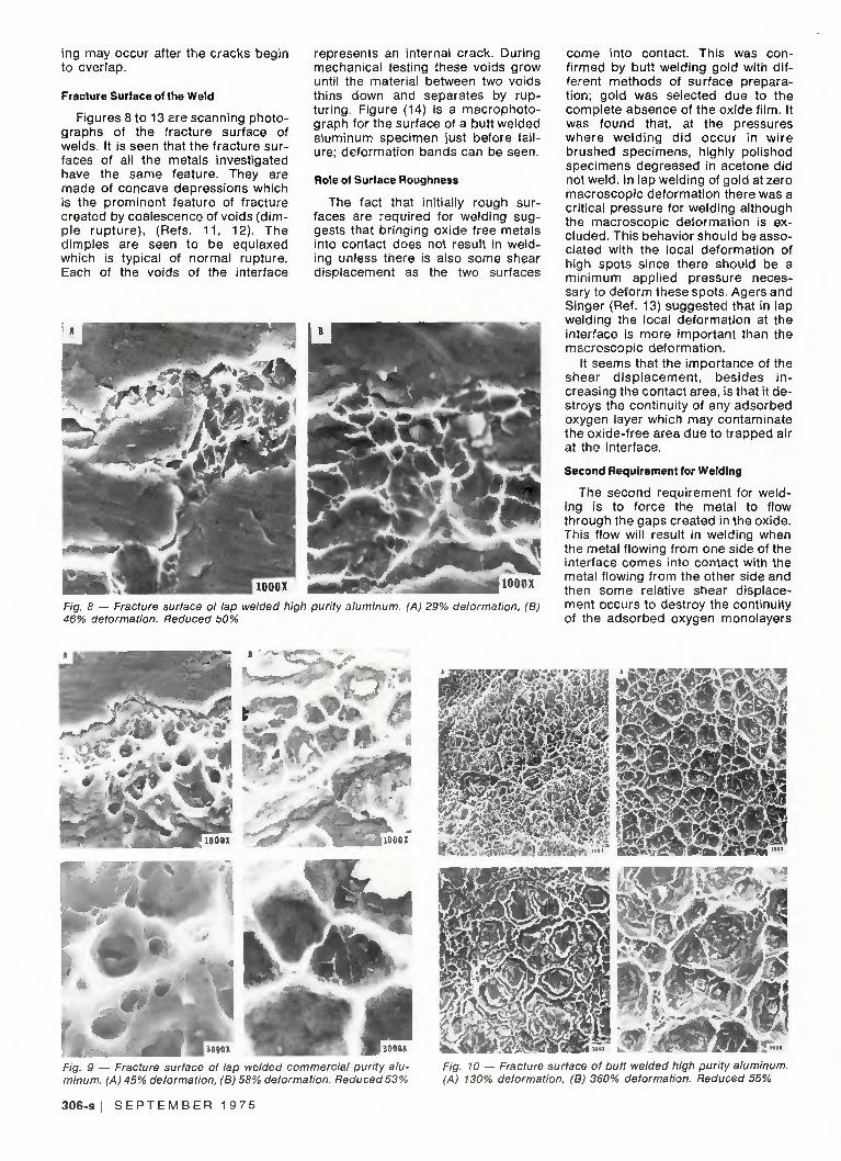
Fracture Surface of the Weld
Figures 8 to 13 are scanning photographs of the fracture surface of welds. It is seen that the fracture surfaces of all the metals investigated have the same feature. They are made of concave depressions which is the prominent feature of fracture created by coalescence of voids (dimple rupture) , (Refs. 11 , 12). The dimples are seen to be equiaxed which is typical of normal rupture. Each of the voids of the interface
represents an internal crack. During mechanical testing these voids grow until the material between two voids thins down and separates by rupturing. Figure (14) is a macrophoto-graph for the surface of a butt welded aluminum specimen just before fai lure; deformation bands can be seen.
Role of Surface Roughness
The fact that initially rough surfaces are required for welding suggests that bringing oxide free metals into contact does not result in welding unless there is also some shear displacement as the two surfaces
1000X
Fig. 8 — Fracture surface of lap welded high purity aluminum. (A) 29% deformation, (B) 46% deformation. Reduced 50%
come into contact. This was conf irmed by butt welding gold with different methods of surface preparat ion; gold was selected due to the complete absence of the oxide fi lm. It was found that, at the pressures where weld ing d id occur in wire brushed specimens, highly polished specimens degreased in acetone did not weld. In lap welding of gold at zero macroscopic deformation there was a critical pressure for welding although the macroscopic deformation is excluded. This behavior should be associated with the local deformation of high spots since there should be a minimum applied pressure necessary to deform these spots. Agers and Singer (Ref. 13) suggested that in lap welding the local deformation at the interface is more important than the macroscopic deformation.
It seems that the importance of the shear d isp lacement , besides in creasing the contact area, is that it destroys the continuity of any adsorbed oxygen layer which may contaminate the oxide-free area due to trapped air at the interface.
Second Requirement for Welding
The second requirement for welding is to force the metal to flow through the gaps created in the oxide. This flow will result in welding when the metal flowing from one side of the interface comes into contact with the metal flowing from the other side and then some relative shear displacement occurs to destroy the continuity of the adsorbed oxygen monolayers
Jam l30"" TB^F^ ,p7ooor Fig. 9 — Fracture surface of lap welded commercial purity aluminum. (A) 45% deformation, (B) 58% deformation. Reduced53%
F0£&l
Fig. 10 — Fracture surface of butt welded high purity aluminum. (A) 130% deformation, (B) 360% deformation. Reduced 55%
306-s I S E P T E M B E R 1 9 7 5

which probably contaminate the surface as a result of the t rapped air at the interface.
High stacking fault energy would be expected to facilitate extrusion of the metal through cracks because of easy cross-slip of glide dislocations.
Except for gold, aluminum, which has high stacking fault energy (~110 ergs/cm2), smallest hardness ratio (Hmetai/Hoxide) and possesses a completely brittle oxide f i lm, was the easiest metal to weld. Although gold has low stacking fault energy, it is easier to weld than aluminum because the first requirement of welding is satisfied everywhere due to the complete absence of the oxide. It is only necessary for deformation to increase the area of contact.
Theoretical Calculation of the Weld Strength
Assume that the oxide f i lm is completely brittle, so the metallic area revealed, which could be welded, is equal to the amount of surface extension that occurs after the surfaces are in intimate enough contact to exclude oxygen.
In butt welding the experimentally measured extension R is given by
R = A - Ao
Ao
where A0 is the original cross-sectional area and A is the instantaneous area at extension R. The true fractional metallic area revealed at a certain extention R is then:
AA
A
R
R + 1
In case of lap welding, if we divide the surface area A0 into small areas A, (i = 1, 2, 3, . . .N) then A0 = NAi and upon applying a deforming stress, the area A; extends to be A, + AAj where
Ai (x, +x,)(y, + y,)-x,y,
A , X I V I
Ax, and Ay, are the extensions in the x and y directions respectively and therefore:
AA; Ax +
^ V i
From the first law of plasticity:
A X i -Wt Az, + =0
Therefore:
AA i Azi
(minus sign means that the strain is compressive)
The total measured reduction
R
and
N = 2-
1
A A ,
At
AA
Ac
the revealed
i
N
1
R
AZ
Z i
true fraction is g liven by:
al
and AA
~ A ~ R + 1 (2)
metallic area
which is in the same form as that for butt welding, Eq. (1). Now, if welding is assumed to occur whenever clean metal surfaces come into contact, then the fractional welded area, f, should be given by:
(D I
Fig. 11 33%
1000X Fracture surface of lap welded high purity copper, 64% deformation. Reduced
Fig. 12 — Fracture surface of lap welded high purity silver, 75% deformation. Reduced 50%
W E L D I N G R E S E A R C H S U P P L E M E N T ! 307-s

Jems
" 1 0 0 0 X * * S * e l ^ * »l
F/g. 13 — Fracture surface of lap welded high purity gold. (A) 3% deformation, (B) 10% deformation. Reduced 50%
Fig. 14 — Macrophotograph tor the surface ot butt welded aluminum specimen just before failure in tension. Reduced 42%
—) + 1 '
(3)
where C is a proportionality constant. If there is a complete matching between the metallic areas over the interface, f has its maximum value given by Eq. (1) or (2), i.e.,
R + 1
but if there is no correlation, f should be given by Eq. (3) if the strength of the weld is Sw and the strength of the metal is Sm, then
SW
Sm = fn • f — y
V R + 1 / (4)
where 1 < n < 2. It would be expected that f cannot attain this maximum value because flow of the metal will be restricted at the edges of the oxide gaps.
Experimental values of (f) were ob-ained from tensile tests, where
fexp —
true ultimate of the weld
tensile strength
true ultimate tensile strength of the metal
The average fractional metallic areas revealed were estimated from the fractographs. The true welded area cannot be est imated direct ly because of the deformation of the welded region which occurs during mechanical testing. The fractional welded area
R R + 1
was calculated from the estimated fractional revealed metallic area
0.6
i r
— Calculated o High Purity Aluminum A 6061 T6 Aluminum Alloy
Deformation (R)
Fig. 15 — Fractional revealed metallic areas estimated from fractographs vs deformation in butt welding of aluminum
0.4
0.2 -
I
—
-
- y
^ / I
I I
A A r
A ^ . CT~
^^o°
Calculated
O High Purity Aluminum
A 606I T6 Alluminum Alloy
I I
I
A
o_ O—-—
-
-
I
Fig. 16
I 2 3
Deformotion (R)
Weld strength vs deformation of butt welded aluminum
308-s j S b H I b M B E H 1 9 7 5

0.4
| 0.3
S 0 . 2 -
•2 0.1 -
-
1
/ o
1
1
/ o
1
1 1 1
— Calcu la ted O High Purity Aluminum
A Commercial Purity Aluminum
1 1 1
-
0.15
0.10
5 0.05 -
0
I I I
— Calculated O High Purity A luminum
A Commercial Purity Aluminum
- \ 1 1
1
1
1
A
1
A
0 6 0.1 0.2 0.3 0.4
Deformation (R) 0.5 0 6
0 0.1 0,2 0.3 0.4 0.5 Oeformation (R)
Fig. 18 — Weld strength vs deformation of lap welded aluminum Fig. 17 — Fractional revealed metallic areas estimated from fractographs vs deformation in lap welding of aluminum
R + 1
Figures 15 to 18 show that:
(a) The experimental values of the fractional metallic areas revealed are in agreement with those calculated theoretically f rom R/(R+1).
(b) The measured strength of the weld is in agreement with that calculated theoretically f rom Eq. (3) with n = 2 using the measured welded area.
(c) The proportionality constant C in Eq. (3) is almost constant and independent of deformation. It has a value of the order of 0.7-0.8.
(d) The experimental values of the weld st rength are comparab le to those calculated on the basis of un-corre lated crack ing of the oxide layers.
It may be concluded from these results that cracks in the oxide layers are uncorrelated and that the weld strength, as a fraction of the strength of the metal, attained after a given deformation is determined by the fractional welded area at that deformation according to the relation:
f = C — Y R + 1 /
With reference to gold, the formula which gives the revealed fractional metal l ic area whi le assuming the presence of a brittle oxide fi lm, is not useful. For gold, the area of clean metal in contact will depend only on the initial roughness of the surface and on the deformation of the high spots as the pressure increases. Figure 19 shows the variation of fexp obtained from mechanical tests with deformation.
The Parameter C. It was shown that some relative shear displacement at the points of contact of oxide-free metal is required for welding and that an initial rough surface facilitates this displacement. These points of con-
0.30
0.25 —
0.20
Fig. 19
0.2 0.3
Deformation (R)
Weld strength vs deformation of lap welded gold
0 5
tact at which the stress is highly concentrated may be cons idered as nuclei of the weld which grow with deformation, and as the number of these nuc le i i nc reases , we ld ing becomes easier. It was also shown that C is almost independent of the deformation.
It is proposed that C depends on the method of preparation of the surface, highly rough surface gives high value of C and vice versa. Therefore, one of the principal functions of wire brushing is to increase the parameter C.
Conclusions
1. Metal to oxide bonding does not con t r i bu te s ign i f i can t l y to weld strength.
2. Initiation of welding of a given metal is determined by cracking of the oxide fi lms which permits contact to gradually develop between clean metal surfaces. Localization of slip into heavy slip bands may be the cause of uncorrelated cracking of the
two oxide layers. 3. Factors that affect the relative
difficulty of pressure welding are: (a) stacking fault energy of the metal, (b) relative hardness of the metal and its oxide film and the mechanical properties of the oxide, and (c) surface roughness prior to welding.
4. The weld strength attained after a given deformation is determined by the fractional area of clean metal surface that has been brought into contact at that deformation.
5. Some relative shear displacement at the points where clean metal surfaces come into contact is necessary for welding.
Acknowledgment
This work was done under the auspices of the U.S. Atomic Energy Commission.
References
1. Tylecote, R. F., The Solid Phase Welding of Metals, St. Martin's Press, 1968, pp. 38, 57, 201.
2. Tylecote, R. F., British Welding Jour-
W E L D I N G R E S E A R C H S U P P L E M E N T ! 309-s

nal, Vol. 1, 117, 1954. 3. Vaidyanath, L. R. and Milner, D. R.,
British Welding Journal, Vol. 7, 1, 1960. 4. Donelan, J. A., British Welding Jour
nal, Vol. 6, 5, 1959. 5. Bowden, F. P. and Tabor, D., Struc
ture and Properties of Solid Surfaces, Gomer, R. and Smith, C. S., eds.
6. Semenov, A. P., Wear 4, 1, 1961. 7. Parks, J. M., Welding Journal, Vol.
32, 5, May, 1953, Res. Suppl., pp. 209-s to 222-s.
8. McEwan, K. M. B. and Milner, D. R., British Welding Journal, Vol. 9, 406, 1962.
9. Barrett, C. S., Acta Met. 1, 2, 1953. 10. Vaidyanath, L. R., Nicholas, M. G.
and Milner, D. R., British Welding Journal, Vol. 6, 13, 1959.
11. Beachem, C. D. and Pelloux, R. M. N., "Electron Fractography, A Tool for the
Study of Micromechanisms of Fracturing Processes," in Fracture Toughness Testing and Its Applications, STP 381, ASTM, Philadelphia, p. 210.
12. Telelman, A. S. and McEvily, A. J. Jr., "Fracture of Metals," in Fracture, An Advanced Treatise, Liebowitz, H., ed., Academic Press, 1969, p. 156.
13. Agers, B. M. and Singer, A. R., British Welding Journal, Vol. 11, 313, 1964.
WRC Bulletin
No. 187 Sept. 1 973
"High-Temperature Brazing"
by H. E. Pattee
This paper, prepared for the Interpretive Reports Committee of the Welding Research Council, is a comprehensive state-of-the-art review. Details are presented on protective atmospheres, heating methods and equipment, and brazing procedures and filler metals for the high-temperature brazing of stainless steels, nickel base alloys, superalloys, and reactive and refractory metals. Also included are an extensive list of references and a bibliography.
The price of WRC Bulletin 187 is $5.00 per copy. Orders should be sent to the Welding Research Council, 345 East 47th Street, New York, N.Y. 10017.
WRC Bulletin No. 197
August 1974
"A Review of Underclad Cracking in Pressure-Vessel Components"
by A. G. Vinckier and A. W. Pense
This report is a summary of data obtained by the PVRC Task Group on Underclad Cracking from the open technical literature and privately sponsored research programs on the topic of underclad cracking, that is, cracking underneath weld cladding in pressure-vessel components. The purpose of the review was to determine what factors contribute to this condition, and to outline means by which it could be either alleviated or eliminated. In the course of the review, a substantial data bank was created on the manufacture, heat treatment, and cladding of heavy-section pressure-vessel steels for nuclear service.
Publication of this report was sponsored by the Pressure-Vessel Research Committee of the Welding Research Council. The price of WRC Bulletin 197 is $5.50. Orders should be sent to the Welding Research Council, 345 E: 47th St., New York, N.Y. 10017.
310-s I S E P T E M B E R 1 9 7 5