Embed Size (px)
Citation preview
Mechanisms
Instructor: Shuvra DasMechanical Engineering Dept.
University of Detroit Mercy
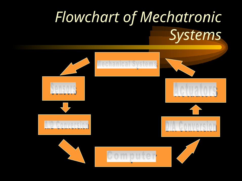
Flowchart of Mechatronic Systems
Mechanism
• A mechanism is a device which transforms motion in a desirable pattern.
• e.g. linear motion to rotational motion, motion in one direction to motion in another direction
• A machine consists of mechanisms that are designed to produce and transmit motion in a certain pre-defined manner.
• Examples: – Slider crank mechanism, transforms rotation into translation
– quick-return mechanism, less time spent per cycle in idling

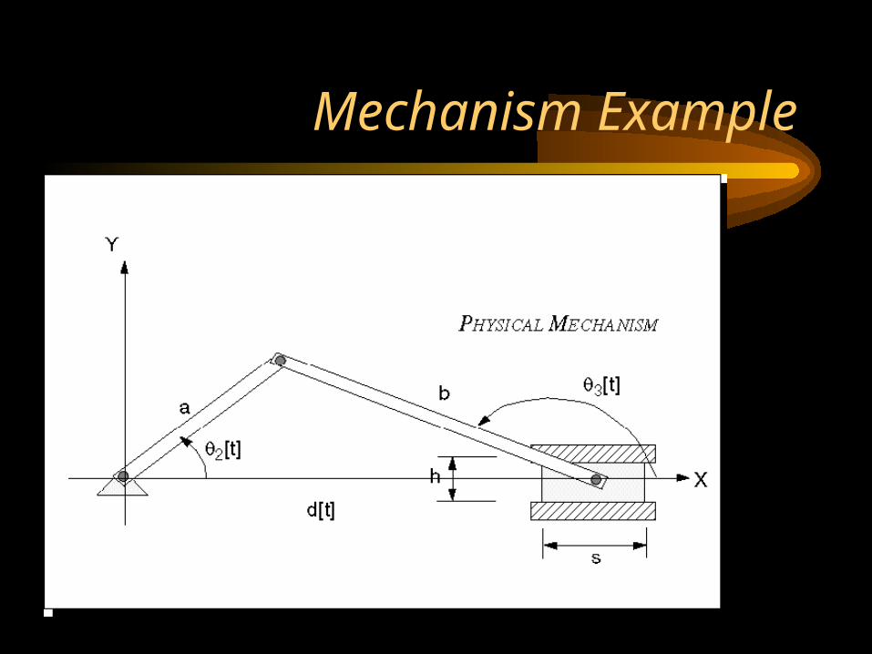
Mechanism Example

Web Based Simulations
• Quick return mechanism: http://www.technologystudent.com/cams/crank1 htm.
• http://www.ul.ie/~kirwanp/linkstoanimations.htm
• http://www.innerauto.com/innerauto/htm/anim.html
• http://www.walterruffler.de/Animat.html
Elements in a mechanism
• Some of the elements:linkages, cams, gears, rack-and-pinion, chains, belt drives, etc.
• Linkages-----can be designed to perform a variety of different tasks.
• Cams ----- cam profile can be designed to prescribe motion in a particular manner.
• gears, chains, belts --- transform rotary motion from one axis to another.
• rack-and -pinion ---- transforms rotational motion to linear motion.
Kinematics
• Dynamics: Kinematics and Kinetics• Kinematics: motion analysis without taking into
consideration the forces that are involved• Kinetics: study of the forces and energy associated
with motion in mechanisms• Mechanisms are made of links and joints
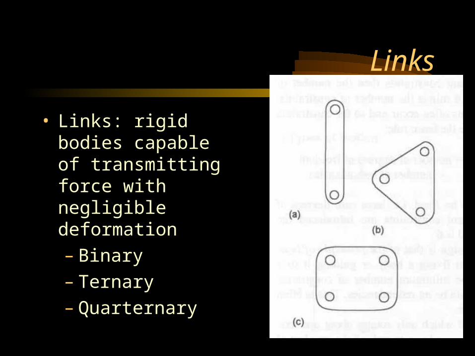
Links
• Links: rigid bodies capable of transmitting force with negligible deformation– Binary– Ternary– Quarternary
Joints
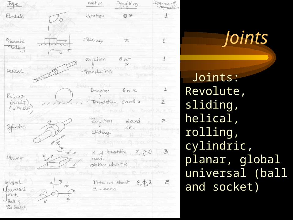
• Joints: Revolute, sliding, helical, rolling, cylindric, planar, global universal (ball and socket)
Kinematic Chains
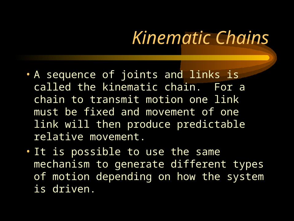
• A sequence of joints and links is called the kinematic chain. For a chain to transmit motion one link must be fixed and movement of one link will then produce predictable relative movement.
• It is possible to use the same mechanism to generate different types of motion depending on how the system is driven.
Mechanism Example
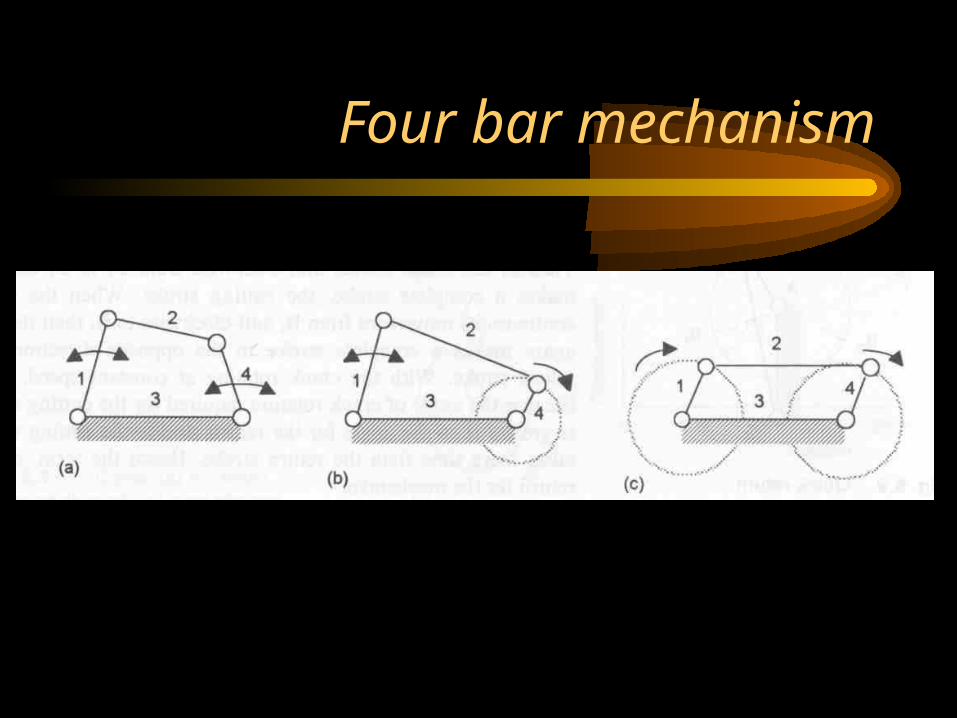
Four bar mechanism
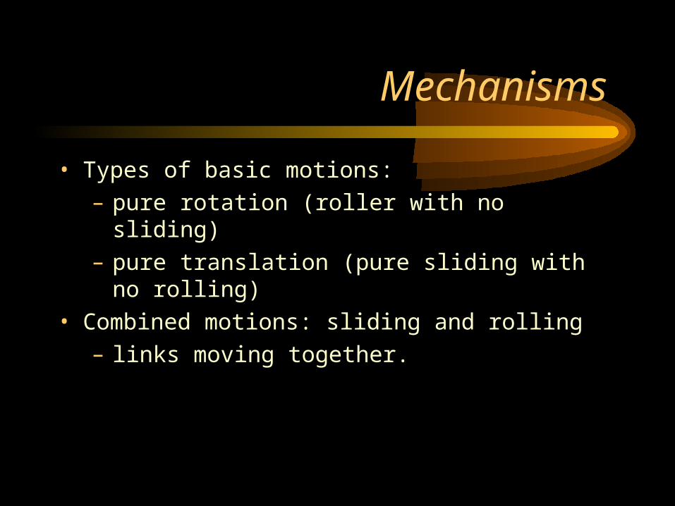
Mechanisms
• Types of basic motions:
– pure rotation (roller with no sliding)
– pure translation (pure sliding with no rolling)
• Combined motions: sliding and rolling
– links moving together.

Degrees of Freedom
• Number of independent co-ordinates needed to determine the position of a link with respect to the ground.
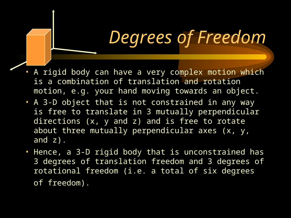
Degrees of Freedom
• A rigid body can have a very complex motion which is a combination of translation and rotation motion, e.g. your hand moving towards an object.
• A 3-D object that is not constrained in any way is free to translate in 3 mutually perpendicular directions (x, y and z) and is free to rotate about three mutually perpendicular axes (x, y, and z).
• Hence, a 3-D rigid body that is unconstrained has 3 degrees of translation freedom and 3 degrees of rotational
freedom (i.e. a total of six degrees of freedom).
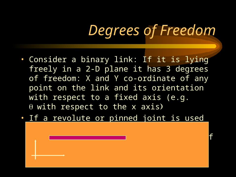
Degrees of Freedom
• Consider a binary link: If it is lying freely in a 2-D plane it has 3 degrees of freedom: X and Y co-ordinate of any point on the link and its orientation with respect to a fixed axis (e.g. with respect to the x axis
• If a revolute or pinned joint is used to tie down a point it loses 2 degrees of freedom and one rotational degree of freedom remains.
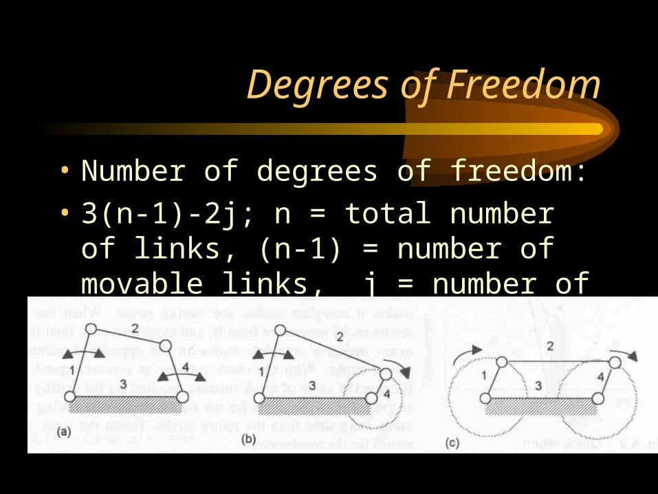
Degrees of Freedom
• Number of degrees of freedom:
• 3(n-1)-2j; n = total number of links, (n-1) = number of movable links, j = number of joints.
•
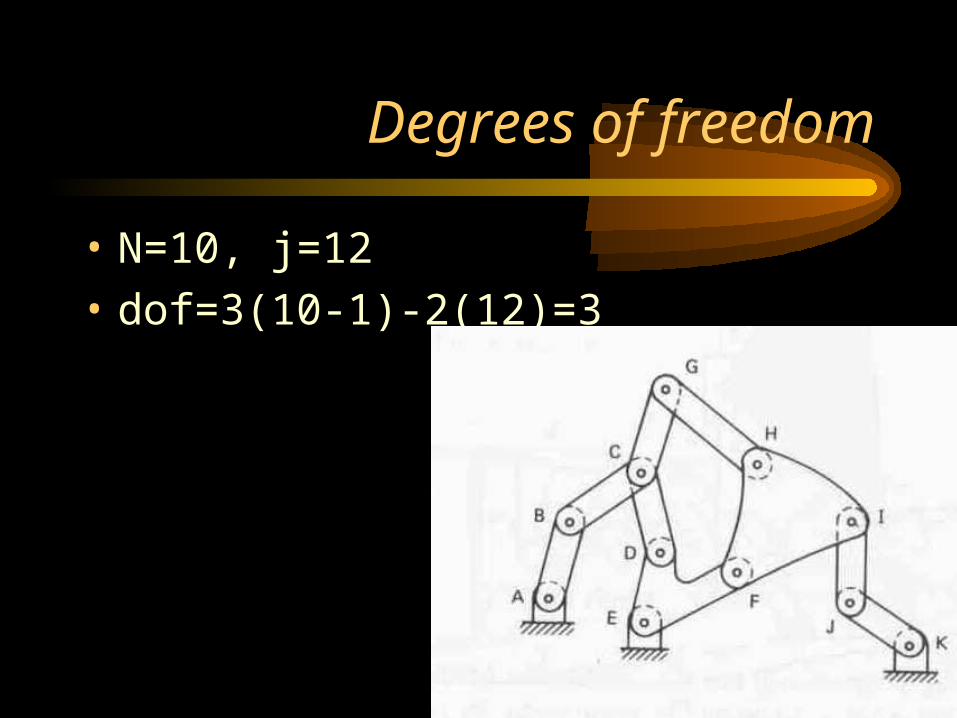
Degrees of freedom
• N=10, j=12
• dof=3(10-1)-2(12)=3
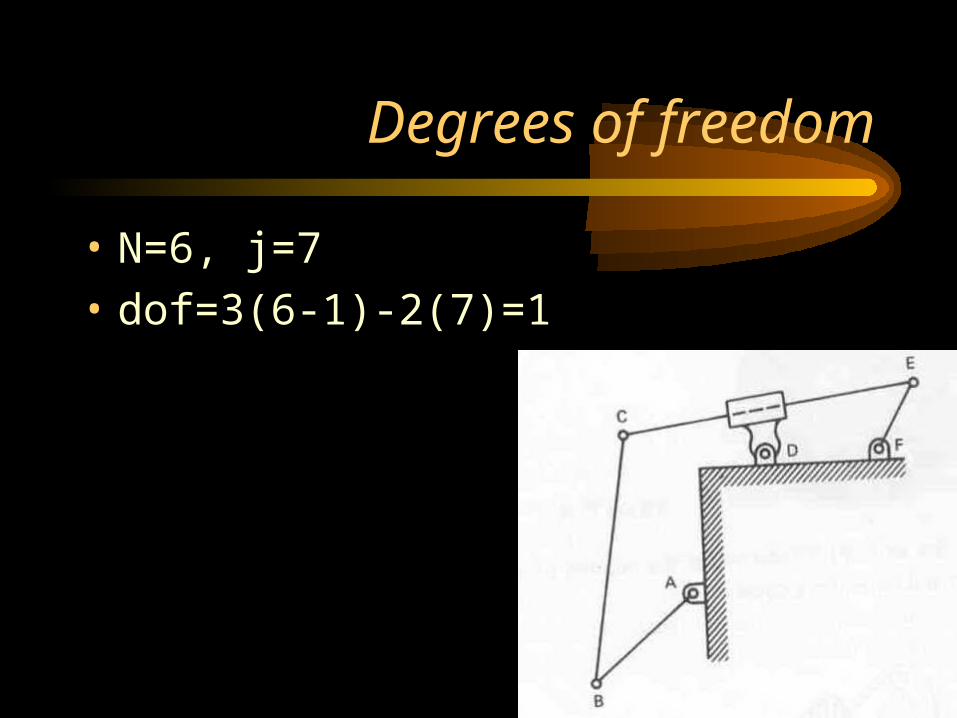
Degrees of freedom
• N=6, j=7
• dof=3(6-1)-2(7)=1
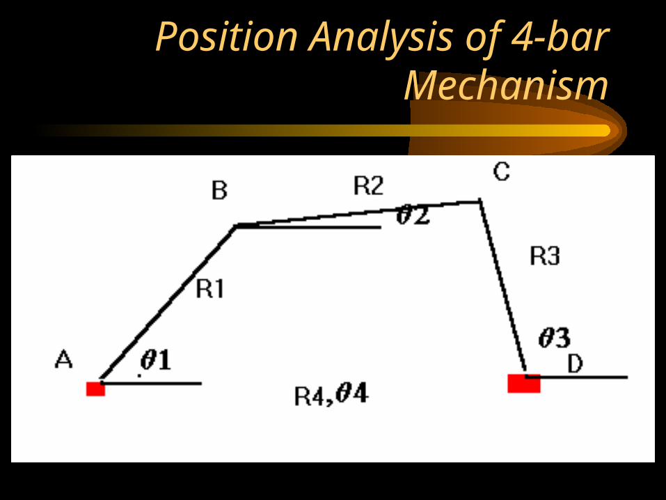
Position Analysis of 4-bar Mechanism
Position Analysis of 4-bar Mechanism
• Points A and D are fixed to the ground and link 4 is the ground link. Links AB, BC and CD are movable. The position analysis is a mathematical representation of the vector sum of the 4 links in the system and is also known as the loop equation. Its representation is as follows:
• R1 e(i1) + R2 e(i2) = R3 e(i3) + R4 e(i4) • R1(Cos 1+i Sin 1)+R2(Cos2 +iSin 2) = R3(Cos3
+iSin3) + R4 (Cos4 + iSin4)
• R1 Cos 1+ R2 Cos 2 = R3 Cos 3 + R4 Cos 4
• (R1 Sin 1+ R2 Sin 2)i = (R3 Sin 3 + R4 Sin 4)i
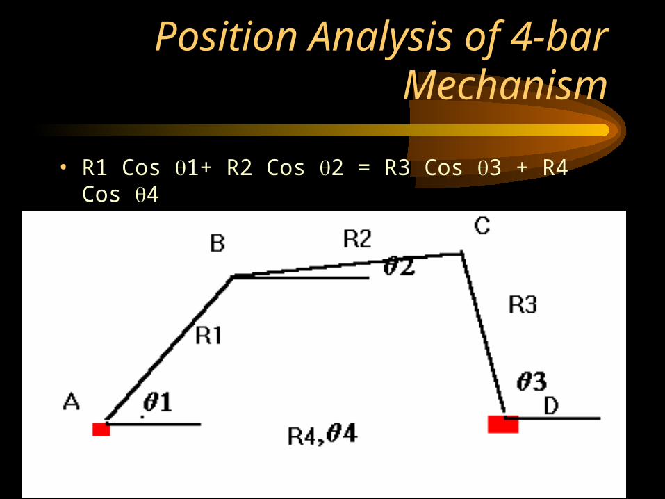
Position Analysis of 4-bar Mechanism
• R1 Cos 1+ R2 Cos 2 = R3 Cos 3 + R4 Cos 4
• R1 Sin 1+ R2 Sin 2 = R3 Sin 3 + R4 Sin 4
Gear Trains
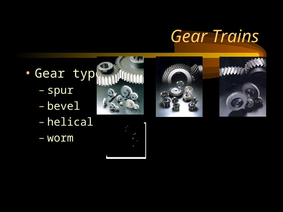
• Gear types:– spur– bevel– helical– worm
Velocity ratio of Gears
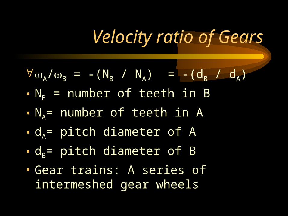
A/B = -(NB / NA) = -(dB / dA)
• NB = number of teeth in B
• NA= number of teeth in A
• dA= pitch diameter of A
• dB= pitch diameter of B
• Gear trains: A series of intermeshed gear wheels
Velocity ratio of Gears
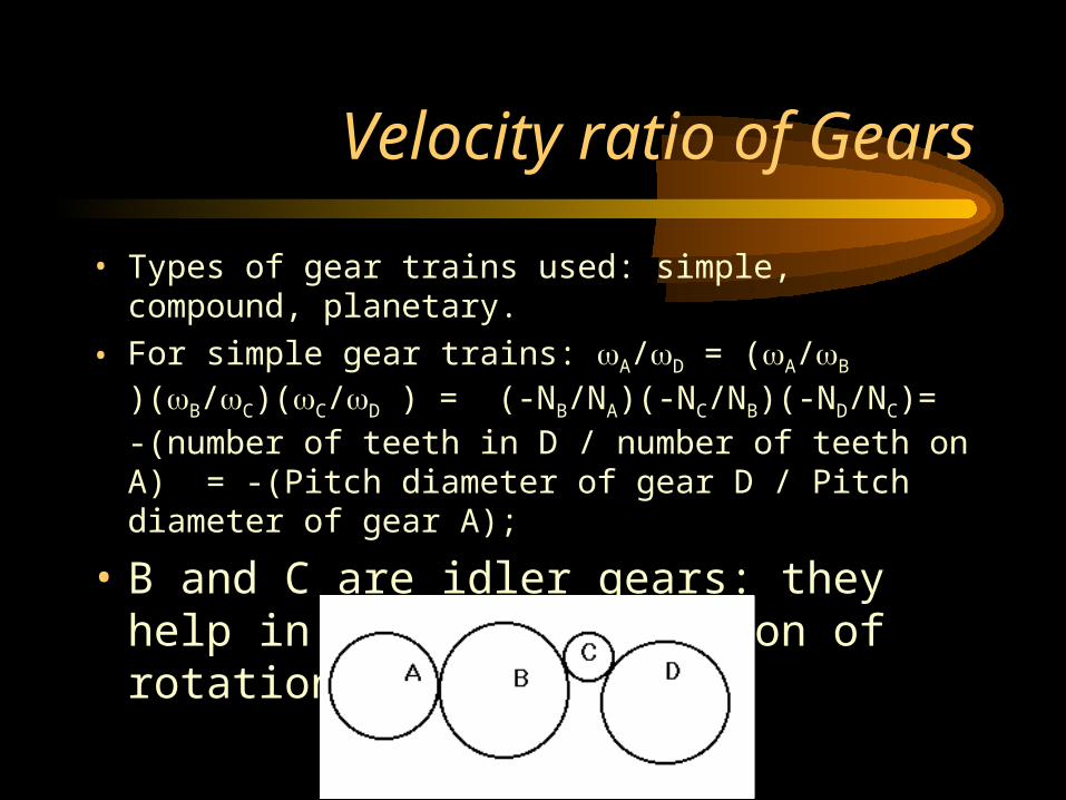
• Types of gear trains used: simple, compound, planetary.
• For simple gear trains: A/D = (A/B )(B/C)(C/D ) = (-NB/NA)(-NC/NB)(-ND/NC)= -(number of teeth in D / number of teeth on A) = -(Pitch diameter of gear D / Pitch diameter of gear A);
• B and C are idler gears: they help in changing direction of rotation only!!!
Velocity Ratio of Gears
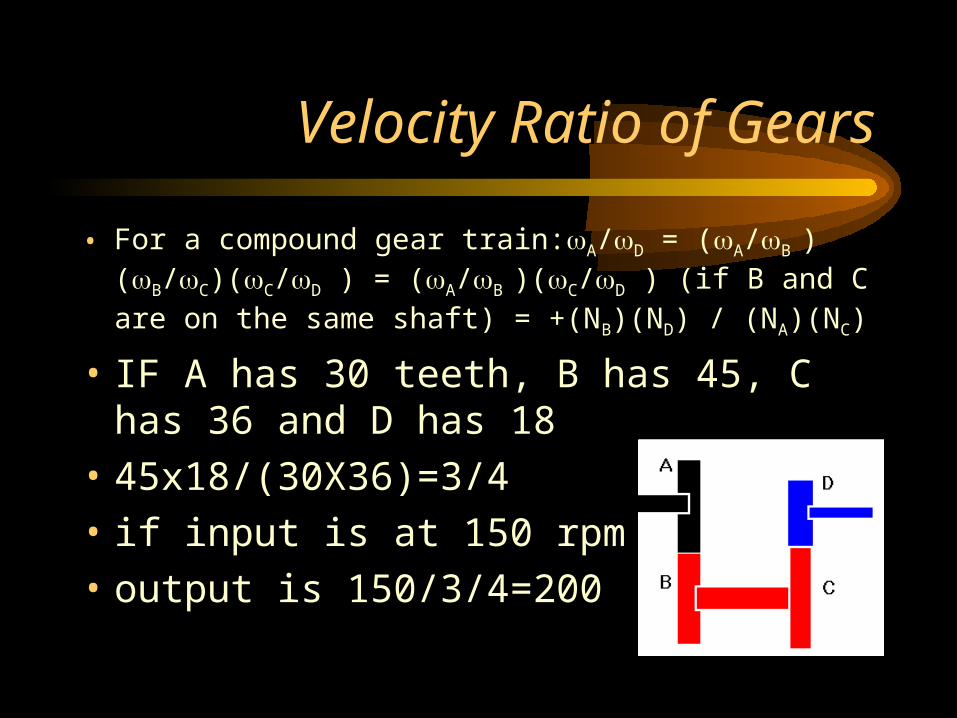
• For a compound gear train:A/D = (A/B )(B/C)(C/D ) = (A/B )(C/D ) (if B and C are on the same shaft) = +(NB)(ND) / (NA)(NC)
• IF A has 30 teeth, B has 45, C has 36 and D has 18
• 45x18/(30X36)=3/4
• if input is at 150 rpm
• output is 150/3/4=200