Embed Size (px)
Citation preview

Slide 1Mechanistic Design of Rail Transit Concrete Crossties
Mechanistic Design of Concrete Monoblock
Crossties for Rail Transit Loading Conditions
APTA Rail Conference
Salt Lake City, UT
23 June, 2015
Matthew V. Csenge, Xiao Lin, Henry E. Wolf, Marcus S. Dersch, and J. Riley Edwards

Slide 2Mechanistic Design of Rail Transit Concrete Crossties
Mechanistic Design of Concrete Monoblock
Crossties for Rail Transit Loading Conditions
2015 APTA Rail Conference
Salt Lake City, UT
23 June 2015
Matthew V. Csenge, Xiao Lin, Henry E. Wolf, Marcus S. Dersch,
J. Riley Edwards and Christopher P.L. Barkan

Slide 3Mechanistic Design of Rail Transit Concrete Crossties
• Background and Motivation
• Project Introduction
– Mission and Objectives
– Methods and Technologies
– Industry Partners and Potential Field
Experimentation Locations
• Introduction to Mechanistic Design
• Load Environment
• Transit Focused Concrete Crosstie
Flexural Analysis
• Future Work
Outline

Slide 4Mechanistic Design of Rail Transit Concrete Crossties
• Mission:
– Characterize the desired performance requirements for
concrete crossties and fastening systems for rail transit
– Quantify the behavior of these systems under load
– Develop resilient infrastructure component design solutions
for concrete crossties and fastening systems for rail transit
• Objectives:
– Investigate field performance demands on concrete crossties
and fastening systems for rail transit applications
– Develop an analytical finite element model
– Validate analytical model and further field research through
lab experimentation
– Develop mechanistic design recommendations for rail transit
applications of concrete crossties and fastening systems
Project Mission and Objectives

Slide 5Mechanistic Design of Rail Transit Concrete Crossties
• American Public Transportation
Association (APTA)
• MTA New York City Transit
(NYCT)
• MetroLink
• Metra
• TriMet
• CXT Concrete Ties, Inc.
• GIC
• Pandrol USA
• Amsted RPS
• Hanson Professional Services, Inc.
• Amtrak
FTA Project Industry Partners
Slide 6Mechanistic Design of Rail Transit Concrete Crossties
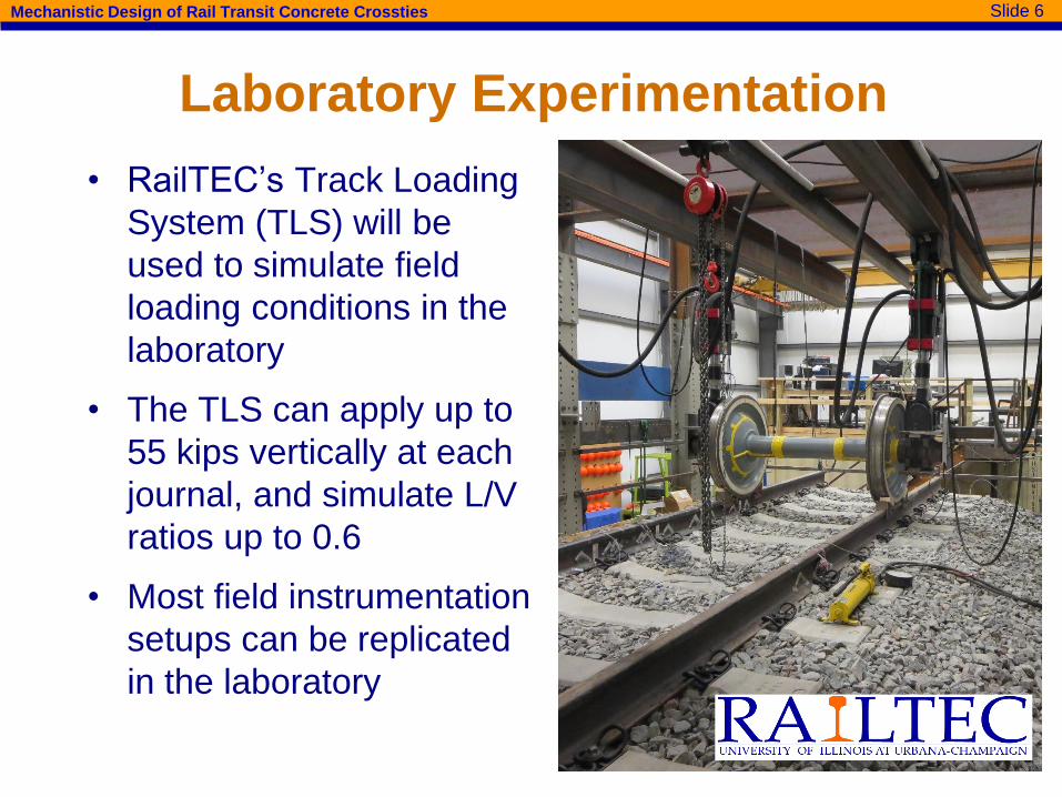
• RailTEC’s Track Loading
System (TLS) will be
used to simulate field
loading conditions in the
laboratory
• The TLS can apply up to
55 kips vertically at each
journal, and simulate L/V
ratios up to 0.6
• Most field instrumentation
setups can be replicated
in the laboratory
Laboratory Experimentation

Slide 7Mechanistic Design of Rail Transit Concrete Crossties
• Instrumentation used in field and lab experimentation
will include:
– Potentiometers – displacement
– Weldable strain gauges –
rail seat loads
– Matrix-based tactile surface sensors –
pressure distribution at rail seat
– Lateral load evaluation devices – lateral load at
fastening system shoulder
Methods and Instrumentation Technologies

Slide 8Mechanistic Design of Rail Transit Concrete Crossties
Field and Laboratory
Experimentation Locations
Light rail: TriMet (Portland, OR)
MetroLink (St. Louis, MO)
Heavy rail: New York City Transit (New York, NY)
Commuter rail: Metra (Chicago, IL)
Slide 9Mechanistic Design of Rail Transit Concrete Crossties
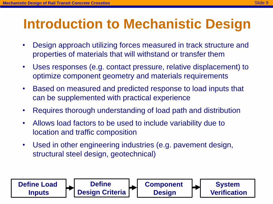
• Design approach utilizing forces measured in track structure and
properties of materials that will withstand or transfer them
• Uses responses (e.g. contact pressure, relative displacement) to
optimize component geometry and materials requirements
• Based on measured and predicted response to load inputs that
can be supplemented with practical experience
• Requires thorough understanding of load path and distribution
• Allows load factors to be used to include variability due to
location and traffic composition
• Used in other engineering industries (e.g. pavement design,
structural steel design, geotechnical)
Introduction to Mechanistic Design
Define Load
Inputs
Define
Design CriteriaComponent
Design
System
Verification
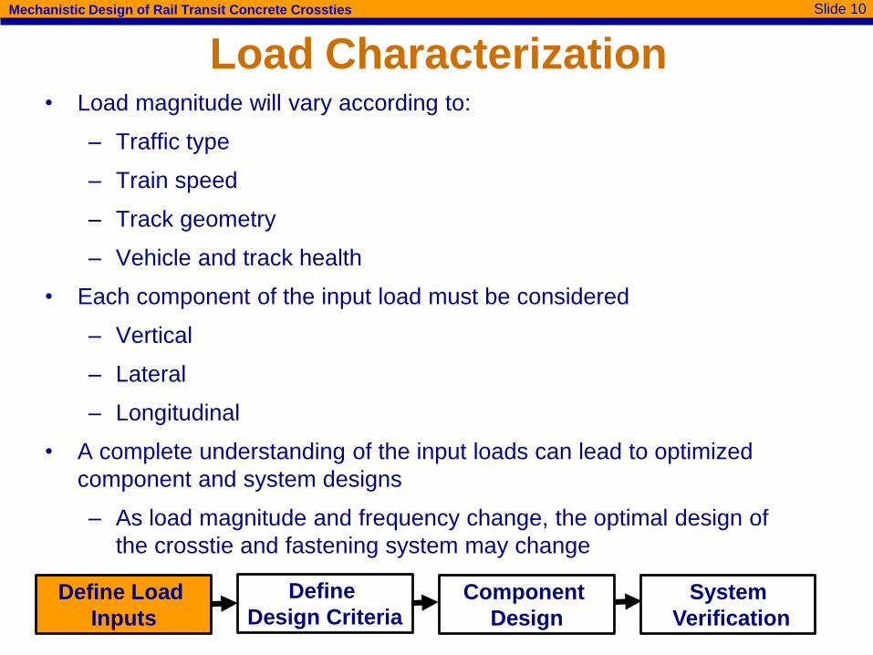
Slide 10Mechanistic Design of Rail Transit Concrete Crossties
Load Characterization• Load magnitude will vary according to:
– Traffic type
– Train speed
– Track geometry
– Vehicle and track health
• Each component of the input load must be considered
– Vertical
– Lateral
– Longitudinal
• A complete understanding of the input loads can lead to optimized
component and system designs
– As load magnitude and frequency change, the optimal design of
the crosstie and fastening system may change
Define Load
Inputs
Define
Design CriteriaComponent
Design
System
Verification

Slide 11Mechanistic Design of Rail Transit Concrete Crossties
Rail Transit Load Environment
• Understanding of transit load environment is a
necessary first step for this project
• Internet resources were used to preliminarily quantify
vehicle weights throughout the United States
• Field experimentation will later be used to further
define load environment

Slide 12Mechanistic Design of Rail Transit Concrete Crossties
Passenger Vehicle Weight Definitions
• PB Light Rail Design Handbook defines:
– AW0: Empty vehicle operating weight
– AW1 (Seated Load)
• Fully seated passenger load + AW0
– AW2 (Design Load)
• Standing passengers at 4/m2 + AW1
– AW3 (Crush Load)
• Standing passengers at 6/m2 + AW1
– AW4 (Structural Design Load)
• Standing passengers at 8/m2 + AW1
AW3 = Maximum Passenger Capacity
× Average Passenger Weight + AW0

Slide 13Mechanistic Design of Rail Transit Concrete Crossties
AW3 Vehicle Weight Calculation
• Passenger car quantity and
capacity
• National Transit Database
(NTD)
Revenue Vehicle Inventory
– Number of active
vehicles
– Seating and
standing capacity
• Empty Car Weight
– Manufacturer
data sheets
Slide 14Mechanistic Design of Rail Transit Concrete Crossties
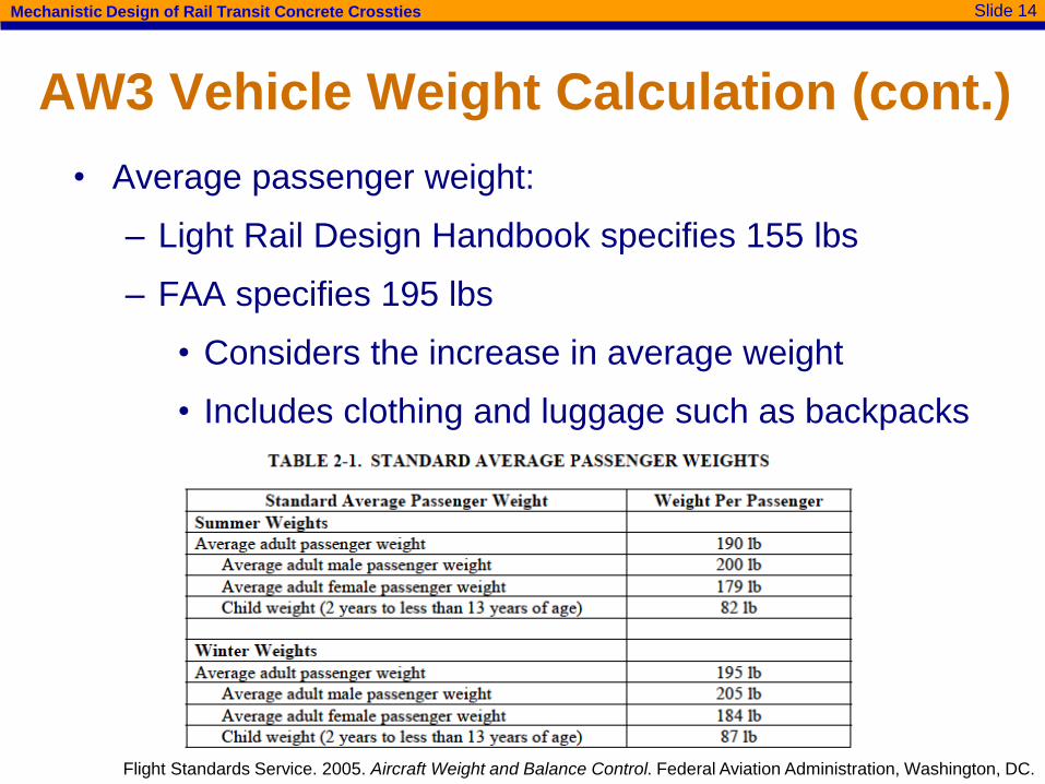
AW3 Vehicle Weight Calculation (cont.)
• Average passenger weight:
– Light Rail Design Handbook specifies 155 lbs
– FAA specifies 195 lbs
• Considers the increase in average weight
• Includes clothing and luggage such as backpacks
Flight Standards Service. 2005. Aircraft Weight and Balance Control. Federal Aviation Administration, Washington, DC.

Slide 15Mechanistic Design of Rail Transit Concrete Crossties
Light Rail, Heavy Rail, and Commuter Rail
Vehicle Weight Distribution
0%
10%
20%
30%
40%
50%
60%
70%
80%
90%
100%
0 50 100 150 200 250
Perc
ent
Exceedin
g
Weight (kips)
Light Rail AW0
Light Rail AW3
Heavy Rail AW0
Heavy Rail AW3
Commuter Rail AW0
Commuter Rail AW3
Slide 16Mechanistic Design of Rail Transit Concrete Crossties
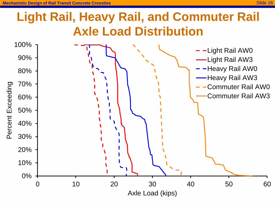
Light Rail, Heavy Rail, and Commuter Rail
Axle Load Distribution
0%
10%
20%
30%
40%
50%
60%
70%
80%
90%
100%
0 10 20 30 40 50 60
Perc
ent
Exceedin
g
Axle Load (kips)
Light Rail AW0
Light Rail AW3
Heavy Rail AW0
Heavy Rail AW3
Commuter Rail AW0
Commuter Rail AW3

Slide 17Mechanistic Design of Rail Transit Concrete Crossties
Application: Flexural Design of CrosstiesCritical Regions for Flexure
Rail Seat Positive (RS+)
Center Negative (C-)

Slide 18Mechanistic Design of Rail Transit Concrete Crossties
Flexural Analysis – MRS+ - AREMA 2014
Factor
Assumed or
Determined
Value
Crosstie Spacing (in) 30
B (8’-3” Crosstie) (in-kips) 320
A (for a 33 kip axle) 33/82=0.40
Speed (mph) 60
V 1.0
𝑀𝑅𝑆+ = 𝐵𝐴𝑉
Where: MRS+ = rail seat positive
bending moment
B = the bending moment
in inch-kips for a particular
crosstie length and spacing
A = the transit load
reduction factor
(axle load/82k)
V = the speed factor (≥1.0)
Equations and figures from Article 30.4.4.1 of the 2014 AREMA Manual
Slide 19Mechanistic Design of Rail Transit Concrete Crossties
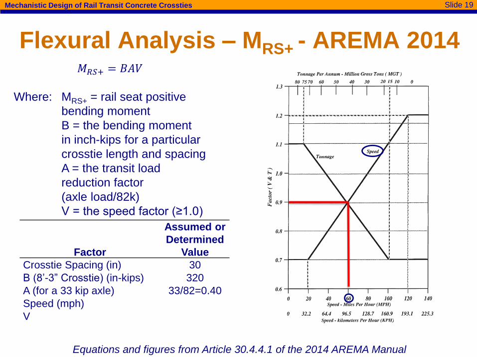
Flexural Analysis – MRS+ - AREMA 2014
Factor
Assumed or
Determined
Value
Crosstie Spacing (in) 30
B (8’-3” Crosstie) (in-kips) 320
A (for a 33 kip axle) 33/82=0.40
Speed (mph) 60
V ≥1.0 1.0
𝑀𝑅𝑆+ = 𝐵𝐴𝑉
Where: MRS+ = rail seat positive
bending moment
B = the bending moment
in inch-kips for a particular
crosstie length and spacing
A = the transit load
reduction factor
(axle load/82k)
V = the speed factor (≥1.0)
Equations and figures from Article 30.4.4.1 of the 2014 AREMA Manual

Slide 20Mechanistic Design of Rail Transit Concrete Crossties
Flexural Analysis – MRS+ - AREMA 2014
Factor
Assumed or
Determined
Value
Crosstie Spacing (in) 30
B (8’-3” Crosstie) (in-kips) 320
A (for a 33 kip axle) 33/82=0.40
Speed (mph) 60
V 1.0
MRS+=BAV=(320)(0.40)(1.0) 128 in-kip
𝑀𝑅𝑆+ = 𝐵𝐴𝑉
Where: MRS+ = rail seat positive
bending moment
B = the bending moment
in inch-kips for a particular
crosstie length and spacing
A = the transit load
reduction factor
(axle load/82k)
V = the speed factor (≥1.0)
Equations and figures from Article 30.4.4.1 of the 2014 AREMA Manual

Slide 21Mechanistic Design of Rail Transit Concrete Crossties
Flexural Analysis – MC- - AREMA 2014
Factor
Assumed or
Determined
Value
Crosstie Length 8’-3”
FC- 0.77
MRS+ 128 in-kip
MC- 99 in-kip
𝑀C− = 𝐹𝐶−𝑀𝑅𝑆+
Where: MC- = center negative
bending moment
FC- = center negative
factor (per AREMA Table
30-4-1)
MRS+ = rail seat positive
bending moment
Equations and figures from Article 30.4.4.1 of the 2014 AREMA Manual

Slide 22Mechanistic Design of Rail Transit Concrete Crossties
Flexural Analysis – MRS+ – Proposed
• Comparison of bending moments
– AREMA 2014
– AREMA 2015 (proposed)
Crosstie Length (L) AREMA 2014 Structural Analysis
8’-3” 128 in-kip 120.5 in-kip
𝑀𝑅𝑆+ =𝑅(𝐿 − 𝑔)
8Where: g = rail seat center-
to-center distance
R = rail seat load
L = crosstie length
g
R R

Slide 23Mechanistic Design of Rail Transit Concrete Crossties
Flexural Analysis – MC- – Proposed
• Comparison of bending moments
– AREMA 2014
– AREMA 2015 (proposed)
Crosstie Length (L) AREMA 2014 Structural Analysis
8’-3” 99 in-kip 99 in-kip
(for α = 0.42)
𝑀𝐶− =𝑅
2
𝐿2 − 1 − 𝛼 𝑐2
2 𝐿 − 1 − 𝛼 𝑐− 𝑔
Where: R = rail seat load
L = crosstie length
α = center support factor
g = rail seat center-
to-center spacing
c = center support
region = 2g - L
g
R R
c
Center support factor (α) currently under review in AREMA
Committee 30 (Ties)

Slide 24Mechanistic Design of Rail Transit Concrete Crossties
Future Work and Path Forward
• Further expand the understanding of vehicle and
infrastructure characteristics for rail transit
– Conduct field and laboratory experimentation to
more accurately characterize the loading
environment for light rail, heavy rail, and commuter
rail transit
• Investigate maintenance equipment wheel loads to
ensure compliance in crosstie and fastener design
• Conduct a survey on the use and performance of
concrete ties and fastening systems
– Objective: Develop an understanding of the most
common types of failures and the design
requirements for optimizing component resiliency

Slide 25Mechanistic Design of Rail Transit Concrete Crossties
Rail Transit Infrastructure SurveyRailTEC Researchers Need Your Help!
• Survey will assist RailTEC
researchers in prioritizing
upcoming FTA-funded
research efforts
• Questions are specific to
concrete crossties and
fastening systems
• Need light, heavy, and
commuter rail responses
• Survey should take only
10-15 minutes
• Free RailTEC mug for first
20 respondents!
Survey of Rail Transit Track
Superstructure Design and
Performance
The first 20 individuals who complete the survey will receive a complimentary
RailTEC mug shipped to the address provided in the survey!
The Rail Transportation and Engineering Center
(RailTEC) at the University of Illinois at Urbana-
Champaign (UIUC) has been awarded a grant
from the FTA titled “Resilient Concrete Crosstie
and Fastening System Designs for Light Rail,
Heavy Rail, and Commuter Rail Transit
Infrastructure”. The primary objective of this
project will be to develop new concrete crosstie
and fastening system designs used in light rail,
heavy rail, and commuter rail infrastructure that
take into account their unique loading conditions.
The RailTEC team, along with its Industry
Partners (listed on right), is conducting a survey to
help determine the most critical aspects of
crossties and fastening systems that should be
made resilient in the face of natural disasters or
other events that place increased stress on
infrastructure and its components. We invite you
to participate in this survey at the following link:
https://goo.gl/QVJuyB
Survey results will be used to guide the field and
laboratory experimental efforts as well as the
analytical finite element (FE) modeling
components of this project.
If you have any questions about this survey,
please feel free to contact RailTEC Graduate
Research Assistant Xiao (Sean) Lin at
FTA Project
Industry Partners
APTA
NYCT
(New York
City, NY)
Metra
(Chicago, IL)
MetroLink
(St. Louis, MO)
TriMet
(Portland, OR)
Pandrol USA
GIC
Amsted RPS
LBFoster, CXT
Concrete Ties
Hanson
Professional
Services, Inc.
Amtrak

Slide 26Mechanistic Design of Rail Transit Concrete Crossties
Acknowledgements
• Funding for this research has been provided by:
– Federal Transit Administration (FTA) (starts 1 Aug. 2015)
– National University Rail Center (NURail Center)
• Industry Partnership and support has been provided by
– American Public Transportation Association (APTA)
– New York City Transit (NYCT)
– Metra (Chicago)
– MetroLink (St. Louis)
– TriMet (Portland, Ore.)
– Pandrol USA
– Amsted RPS / Amsted Rail, Inc.
– LBFoster
– GIC Inc.
– Hanson Professional Services, Inc.
– Amtrak
• UIUC Students Sean Lin and Henry Wolf
FTA Industry Partners:

Slide 27Mechanistic Design of Rail Transit Concrete Crossties
Contact Information
Matthew V. Csenge
Manager of Experimentation
Xiao (Sean) Lin
Graduate Research Assistant
Henry E. Wolf
Graduate Research Assistant
Marcus S. Dersch
Senior Research Engineer
J. Riley Edwards
Sen. Lecturer and Research Sci.