Embed Size (px)
Citation preview
Mr. Manoj Rajale
UNIT –III
Data Acquisition & Microcontroller
System
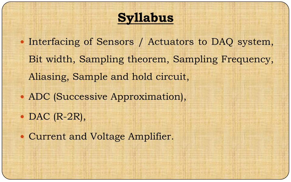
Syllabus
Interfacing of Sensors / Actuators to DAQ system,
Bit width, Sampling theorem, Sampling Frequency,
Aliasing, Sample and hold circuit,
ADC (Successive Approximation),
DAC (R-2R),
Current and Voltage Amplifier.
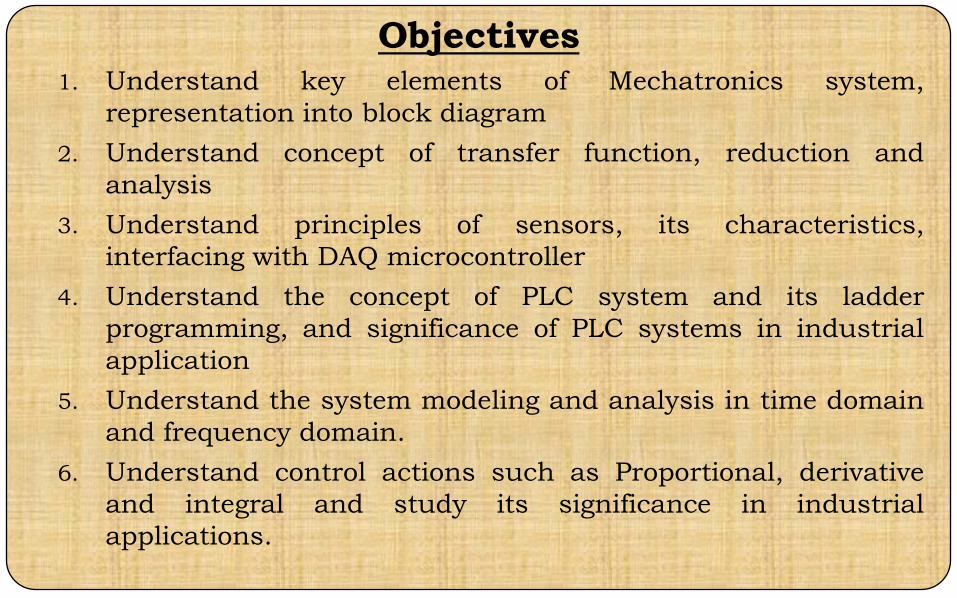
Objectives1. Understand key elements of Mechatronics system,
representation into block diagram
2. Understand concept of transfer function, reduction and
analysis
3. Understand principles of sensors, its characteristics,
interfacing with DAQ microcontroller
4. Understand the concept of PLC system and its ladder
programming, and significance of PLC systems in industrial
application
5. Understand the system modeling and analysis in time domain
and frequency domain.
6. Understand control actions such as Proportional, derivative
and integral and study its significance in industrial
applications.
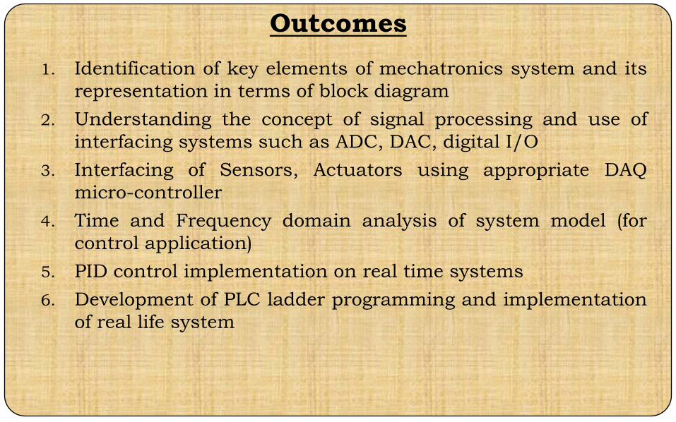
Outcomes
1. Identification of key elements of mechatronics system and its
representation in terms of block diagram
2. Understanding the concept of signal processing and use of
interfacing systems such as ADC, DAC, digital I/O
3. Interfacing of Sensors, Actuators using appropriate DAQ
micro-controller
4. Time and Frequency domain analysis of system model (for
control application)
5. PID control implementation on real time systems
6. Development of PLC ladder programming and implementation
of real life system
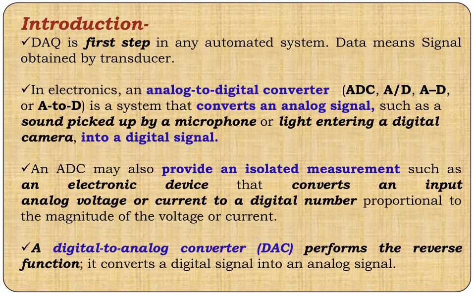
Introduction-DAQ is first step in any automated system. Data means Signal
obtained by transducer.
In electronics, an analog-to-digital converter (ADC, A/D, A–D,
or A-to-D) is a system that converts an analog signal, such as a
sound picked up by a microphone or light entering a digital
camera, into a digital signal.
An ADC may also provide an isolated measurement such as
an electronic device that converts an input
analog voltage or current to a digital number proportional to
the magnitude of the voltage or current.
A digital-to-analog converter (DAC) performs the reverse
function; it converts a digital signal into an analog signal.
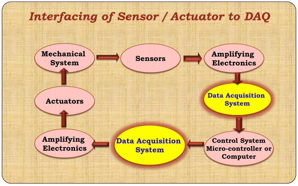
Interfacing of Sensor / Actuator to DAQ
Mechanical
SystemSensors
Actuators
Amplifying
Electronics
Amplifying
Electronics
Control System
Micro-controller or
Computer
Data Acquisition
System
Data Acquisition
System

What is Analog / Digital Signal ?
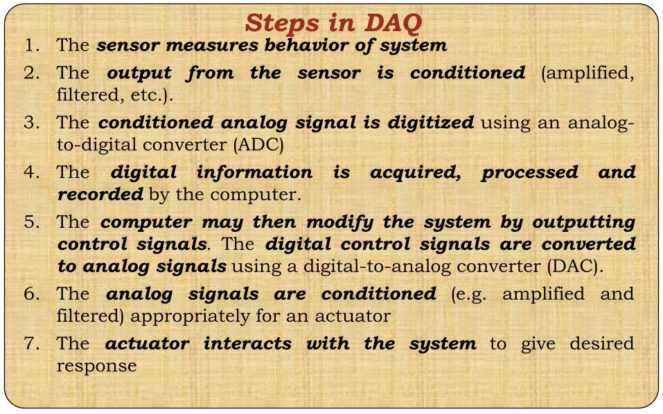
Steps in DAQ1. The sensor measures behavior of system
2. The output from the sensor is conditioned (amplified,
filtered, etc.).
3. The conditioned analog signal is digitized using an analog-
to-digital converter (ADC)
4. The digital information is acquired, processed and
recorded by the computer.
5. The computer may then modify the system by outputting
control signals. The digital control signals are converted
to analog signals using a digital-to-analog converter (DAC).
6. The analog signals are conditioned (e.g. amplified and
filtered) appropriately for an actuator
7. The actuator interacts with the system to give desired
response

Interfacing of Sensor / Actuator to DAQ
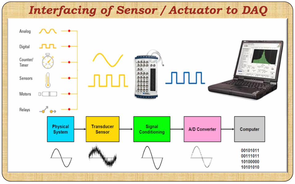
Interfacing of Sensor / Actuator to DAQ

Analog - Digital Converter
Analog-Digital Conversion Process
Engineering signals are continuous.
Eg: voltage that varies over time; a chemical reaction rate that
depends on temperature, etc.
ADC and DAC allow digital computers to interact with these
signals.

How does ADC Work?Converts an analog voltage level to a digital number
Digital Numbers can be effectively handled by microcontrollers, analog
levels
Digital numbers are non-fractional
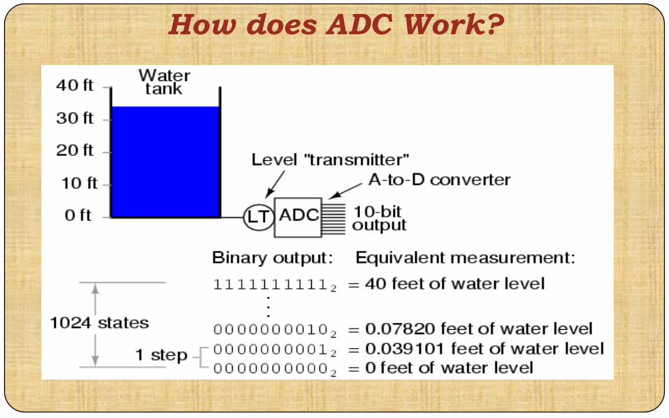
How does ADC Work?

An electronic integrated circuit which transforms a signal
from analog (continuous) to digital (discrete) form.
Analog signals are directly measurable quantities.
Digital signals only have two states. For digital computer, we
refer to binary states, 0 and 1.
Microprocessors can only perform complex processing on
digitized signals.
ADC Provides a link between the analog world of
transducers and the digital world of signal processing and
data handling.
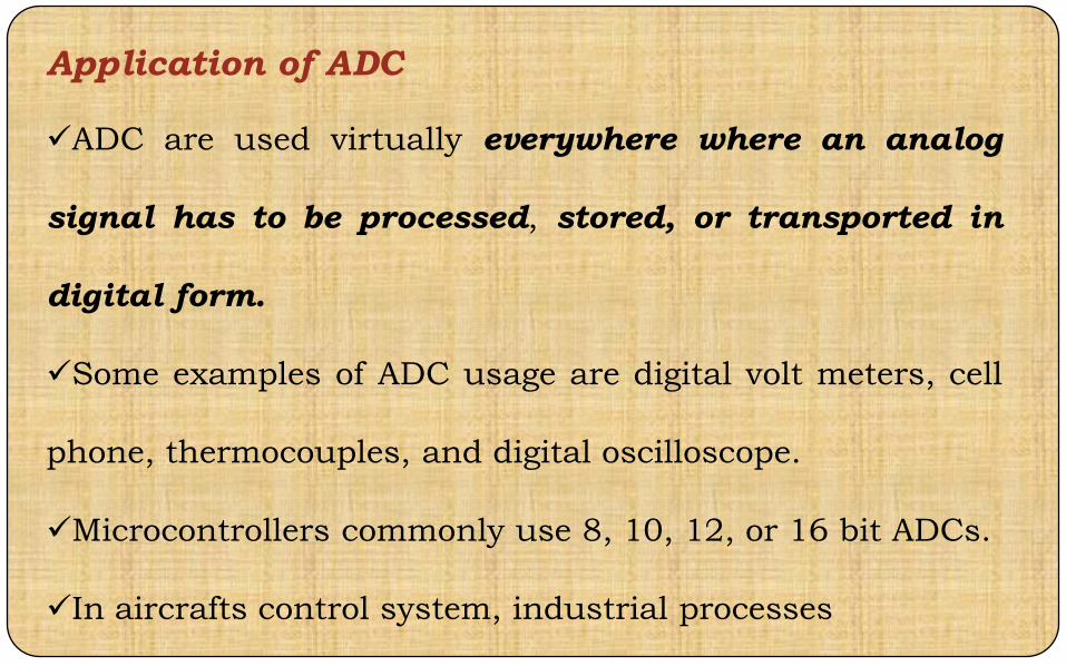
Application of ADC
ADC are used virtually everywhere where an analog
signal has to be processed, stored, or transported in
digital form.
Some examples of ADC usage are digital volt meters, cell
phone, thermocouples, and digital oscilloscope.
Microcontrollers commonly use 8, 10, 12, or 16 bit ADCs.
In aircrafts control system, industrial processes
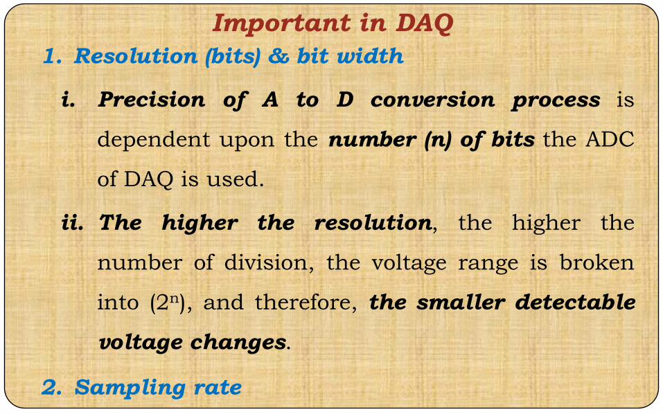
Important in DAQ
1. Resolution (bits) & bit width
i. Precision of A to D conversion process is
dependent upon the number (n) of bits the ADC
of DAQ is used.
ii. The higher the resolution, the higher the
number of division, the voltage range is broken
into (2n), and therefore, the smaller detectable
voltage changes.
2. Sampling rate
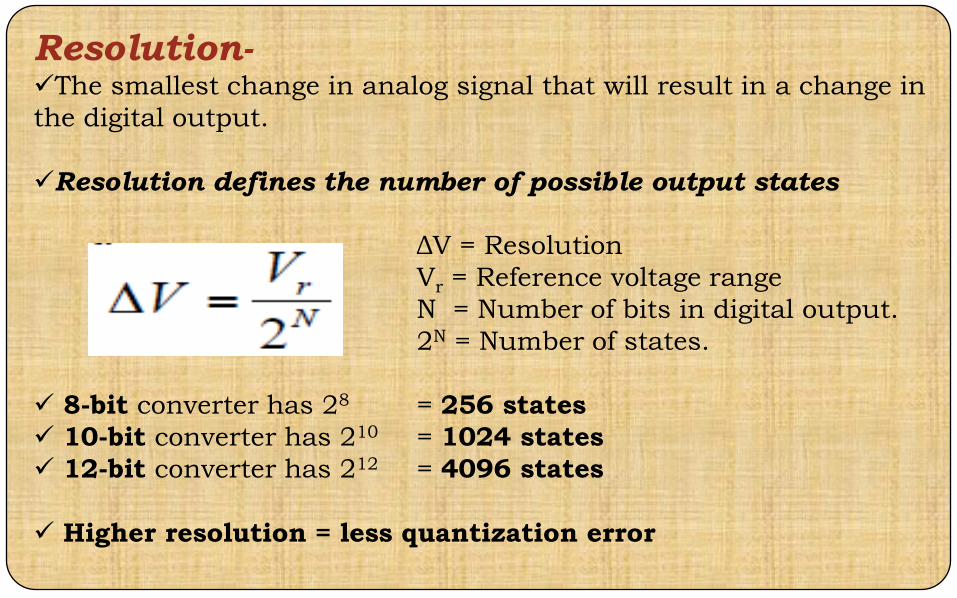
Resolution-The smallest change in analog signal that will result in a change in
the digital output.
Resolution defines the number of possible output states
ΔV = Resolution
Vr = Reference voltage range
N = Number of bits in digital output.
2N = Number of states.
8-bit converter has 28 = 256 states
10-bit converter has 210 = 1024 states
12-bit converter has 212 = 4096 states
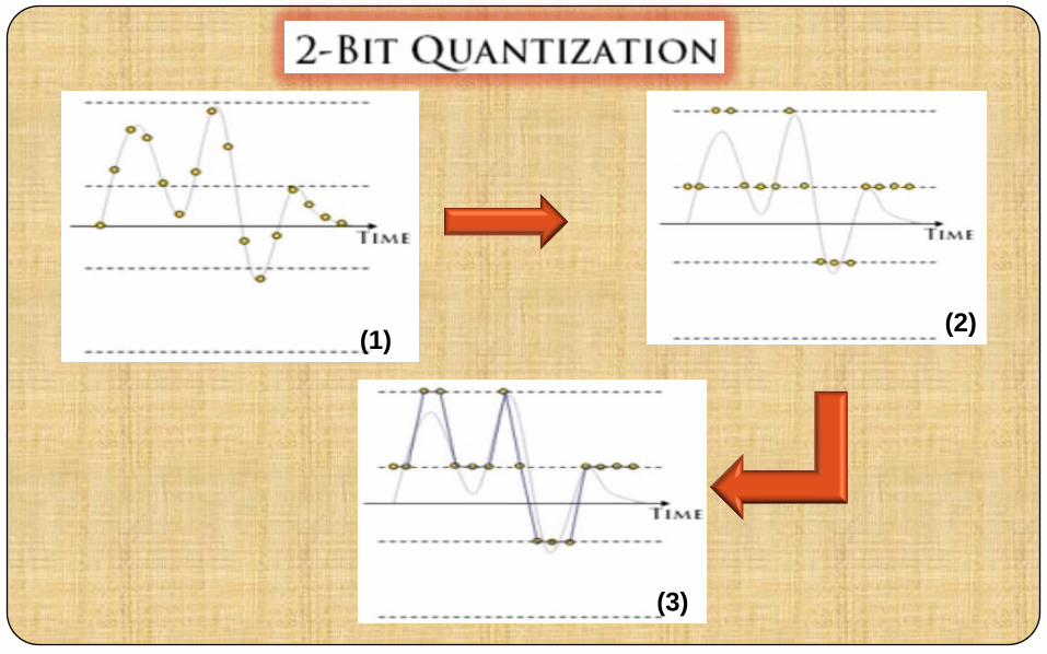
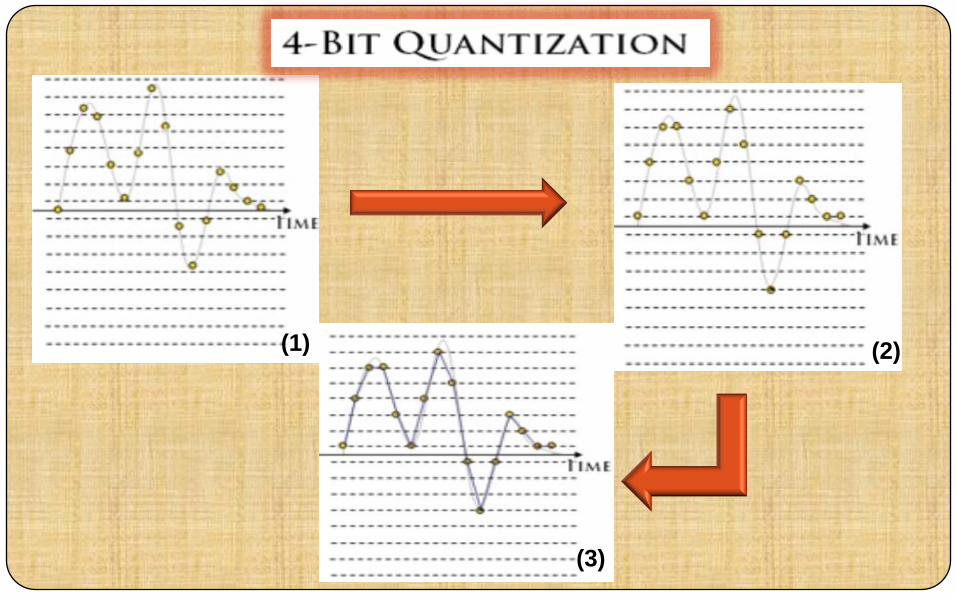
Higher resolution = less quantization error
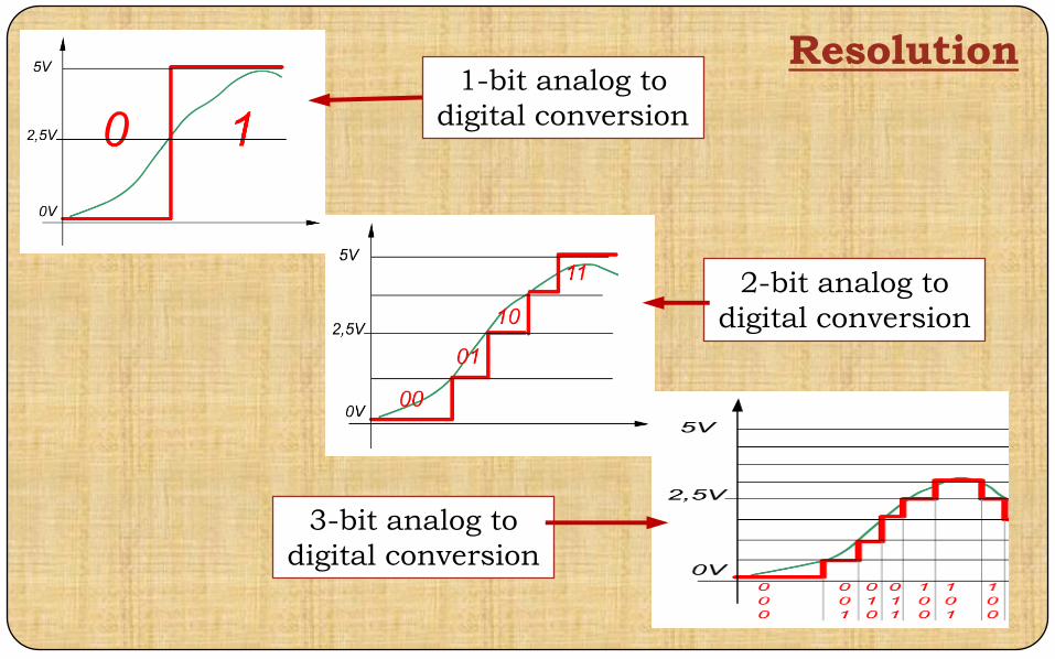
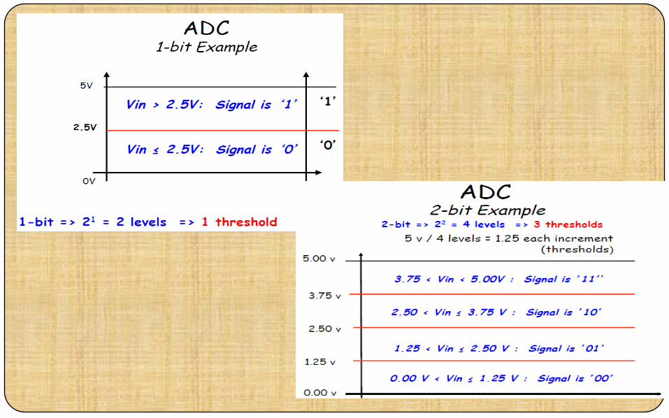
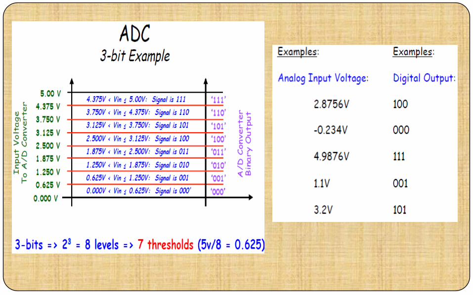
Resolution1-bit analog to
digital conversion
2-bit analog to
digital conversion
3-bit analog to
digital conversion
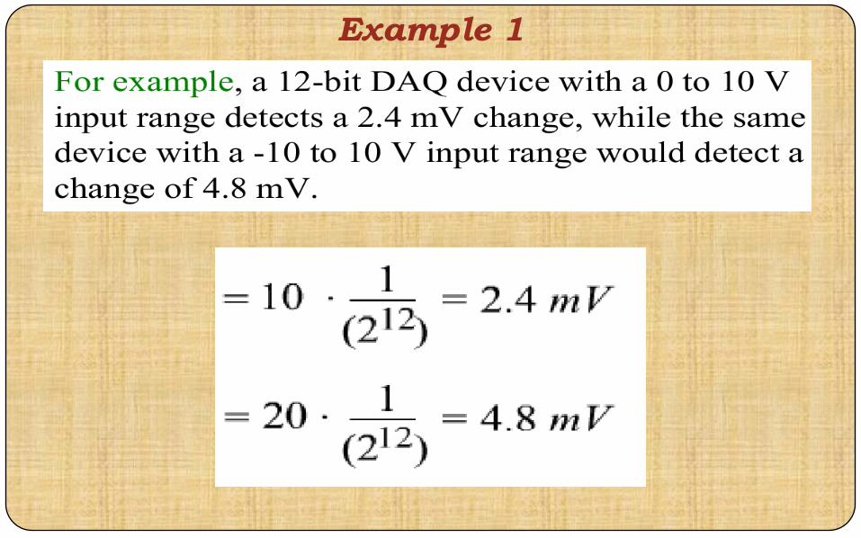
Example 1
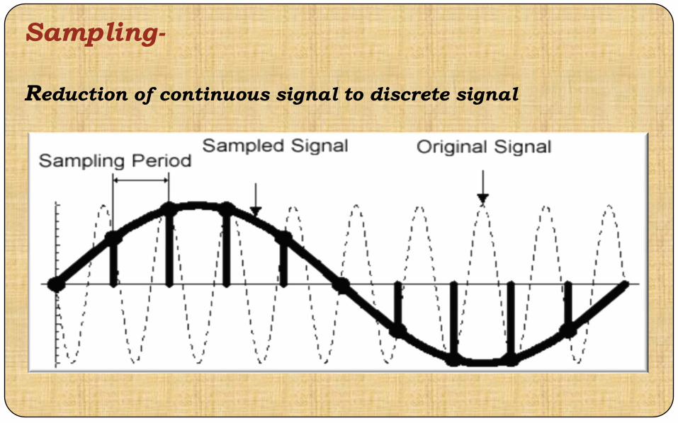
Sampling-
Reduction of continuous signal to discrete signal
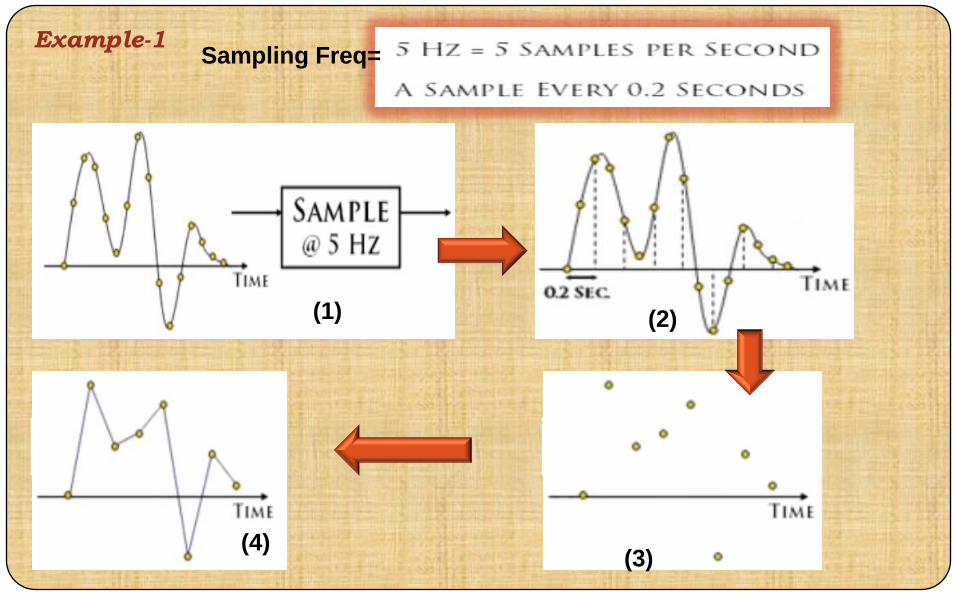
Example-1
(1) (2)
(3)(4)
Sampling Freq=
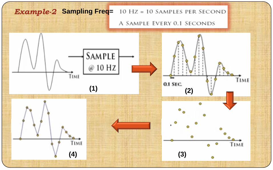
Example-2
(1) (2)
(3)(4)
Sampling Freq=
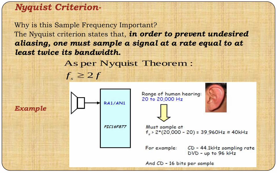
Nyquist Criterion-
Why is this Sample Frequency Important?
The Nyquist criterion states that, in order to prevent undesired
aliasing, one must sample a signal at a rate equal to at
least twice its bandwidth.
Example
ffs
2
:TheoremNyquist per As

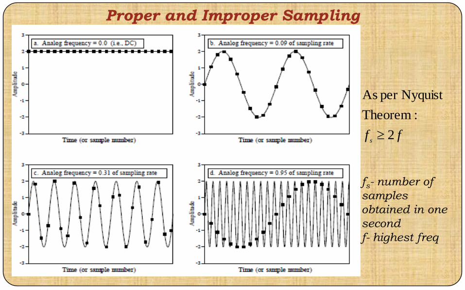
Proper and Improper Sampling
ffs
2
:Theorem
Nyquist per As
fs- number of
samples
obtained in one
second
f- highest freq
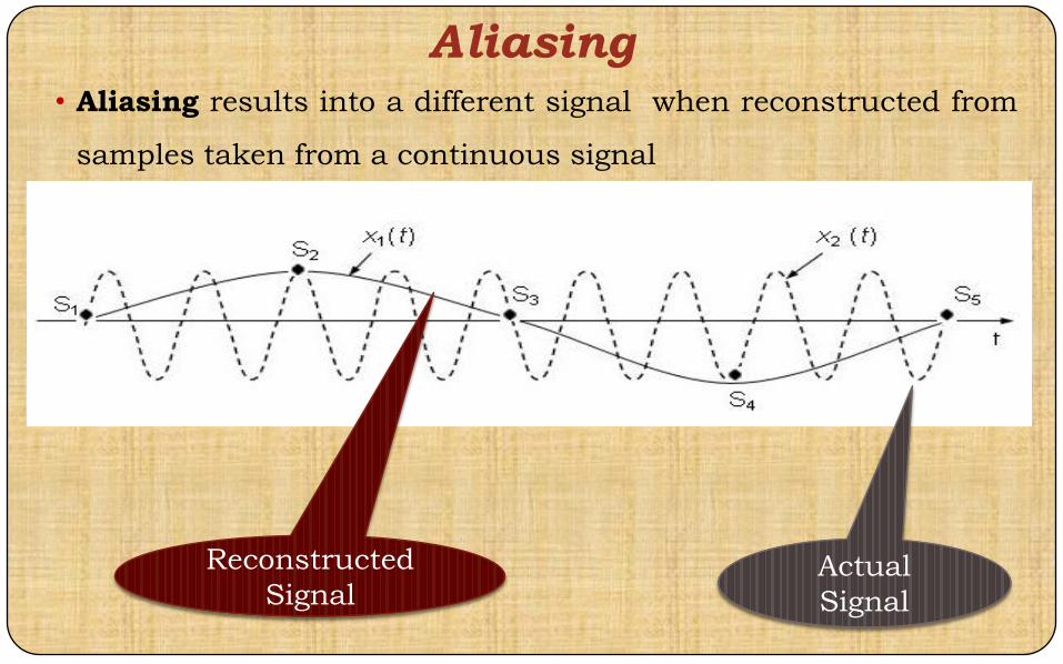
Aliasing• Aliasing results into a different signal when reconstructed from
samples taken from a continuous signal
Actual
Signal
Reconstructed
Signal
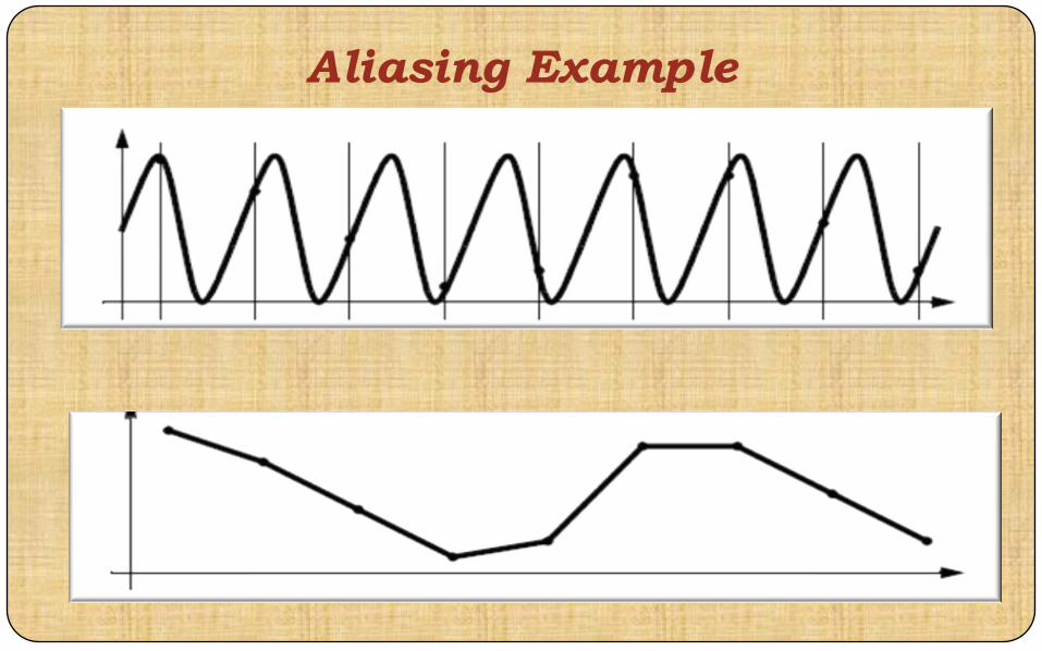
Aliasing Example
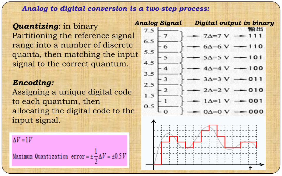
Quantizing: in binary
Partitioning the reference signal
range into a number of discrete
quanta, then matching the input
signal to the correct quantum.
Encoding:
Assigning a unique digital code
to each quantum, then
allocating the digital code to the
input signal.
Analog Signal Digital output in binary
Analog to digital conversion is a two-step process:

(1) (2)
(3)
(1)(2)
(3)
(1) (2)
(3)
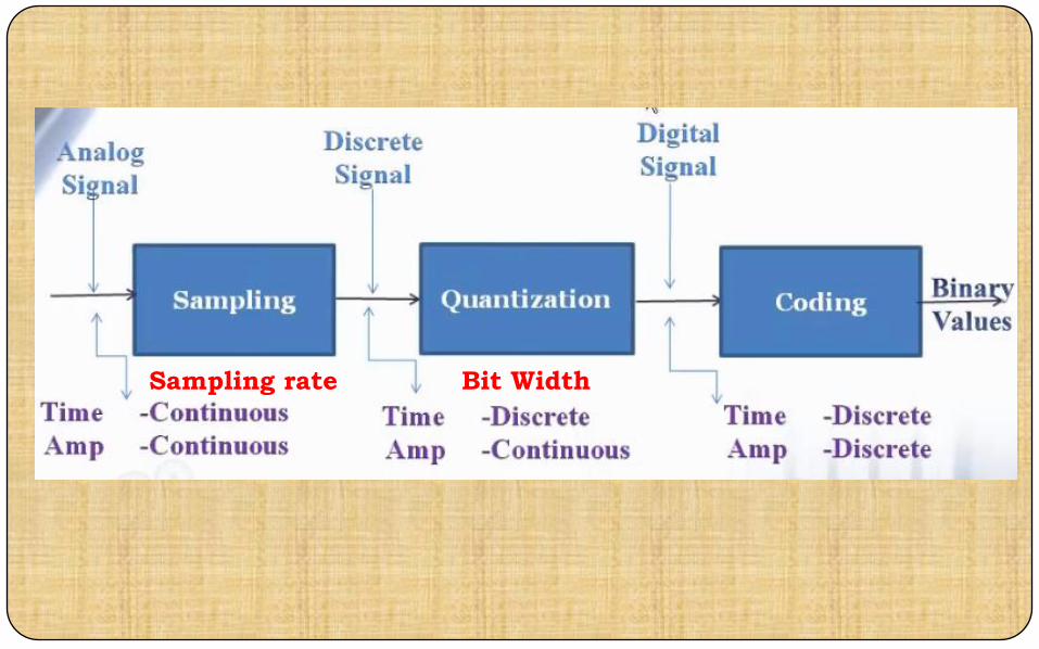
Sampling rate Bit Width

There are two ways to best improve the accuracy of
A/D conversion:1. increasing the resolution which improves the accuracy in
measuring the amplitude of the analog signal.
2. increasing the sampling rate which increases the maximum
frequency that can be measured.
ImprovedLow Accuracy

Sample and Hold Operation
Sample and Hold Circuit
SHA is used in ADC, to stabilize the voltage while it is being
converted to a digital value
SHA consists of a voltage holding capacitor and a voltage follower
When the switch is closed, the output voltage is equal to the input
voltage
When the switch is open, capacitor holds the voltage corresponding to
the last sampled value
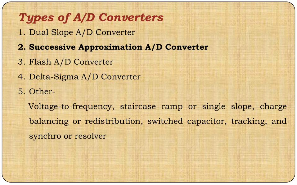
Types of A/D Converters
1. Dual Slope A/D Converter
2. Successive Approximation A/D Converter
3. Flash A/D Converter
4. Delta-Sigma A/D Converter
5. Other-
Voltage-to-frequency, staircase ramp or single slope, charge
balancing or redistribution, switched capacitor, tracking, and
synchro or resolver
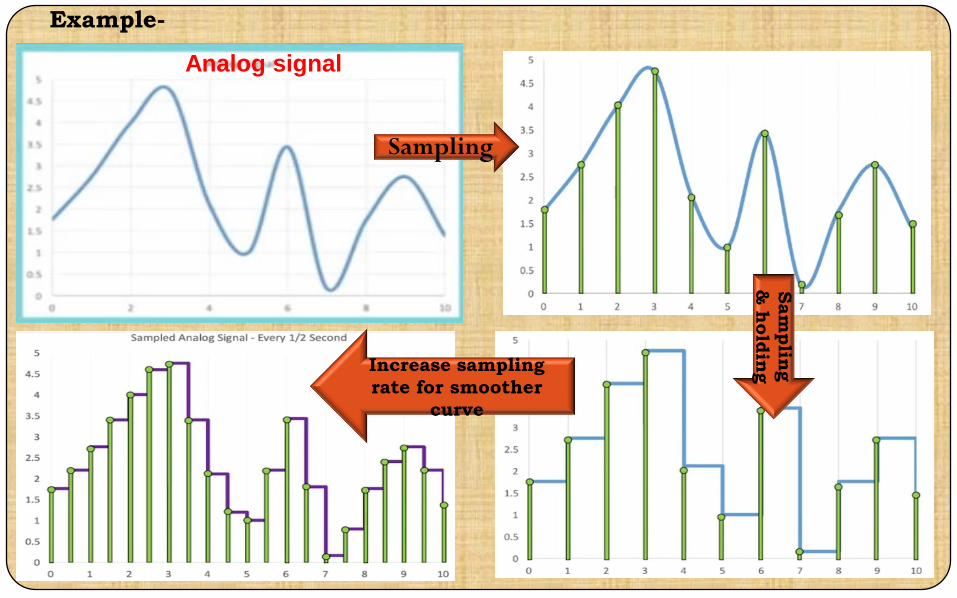
Example-
Analog signal
SamplingSam
plin
g
& h
old
ingIncrease sampling
rate for smoother
curve

Cont…..
Quantizing
analog signal

Least Significant Bit (LSB) and Most
Significant Bit (MSB)
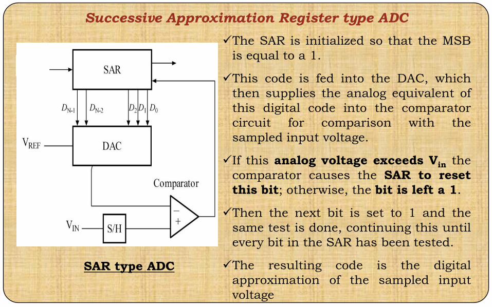
Successive Approximation Register type ADC
SAR type ADC
The SAR is initialized so that the MSB
is equal to a 1.
This code is fed into the DAC, which
then supplies the analog equivalent of
this digital code into the comparator
circuit for comparison with the
sampled input voltage.
If this analog voltage exceeds Vin the
comparator causes the SAR to reset
this bit; otherwise, the bit is left a 1.
Then the next bit is set to 1 and the
same test is done, continuing this until
every bit in the SAR has been tested.
The resulting code is the digital
approximation of the sampled input
voltage

Uses a n-bit DAC to compare DAC and original analog results.
Uses SAR supplies an approximate digital code to DAC of Vin.
Comparison changes digital output to bring it closer to the input value.
Uses Closed-Loop Feedback Conversion

SAR ADC
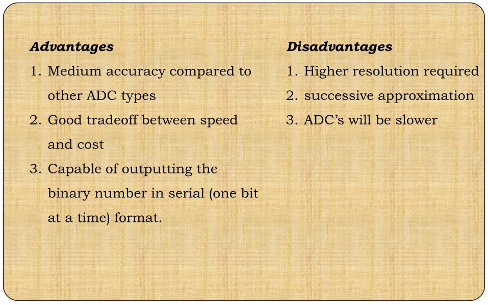
Advantages
1. Medium accuracy compared to
other ADC types
2. Good tradeoff between speed
and cost
3. Capable of outputting the
binary number in serial (one bit
at a time) format.
Disadvantages
1. Higher resolution required
2. successive approximation
3. ADC’s will be slower

Example 1
For a 10 bit ADC with a Vref =1volts, find the
digital equivalent of Vin=0.6
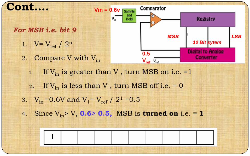
Cont….
For MSB i.e. bit 9
1. V= Vref / 2n
2. Compare V with Vin
i. If Vin is greater than V , turn MSB on i.e. =1
ii. If Vin is less than V , turn MSB off i.e. = 0
3. Vin =0.6V and V1= Vref / 21 =0.5
4. Since Vin> V, 0.6> 0.5, MSB is turned on i.e. = 1
0.5
Vref
Vin = 0.6v
MSB LSB
10 Bit sytem

Cont….
For MSB 1 i.e. bit 8
1. Compare Vin=0.6 V to V2=V1 + Vref/22
= 0.5 + 0.25 = 0.75V
1. Since 0.6<0.75, MSB 1 is turned off i.e = 0
For MSB 2 i.e. bit 7
1. Compare Vin=0.6 V with V3=(V1+Vref/23)= 0.625
2. Since 0.6<0.625, MSB 2 is turned off i.e = 0
Cont….
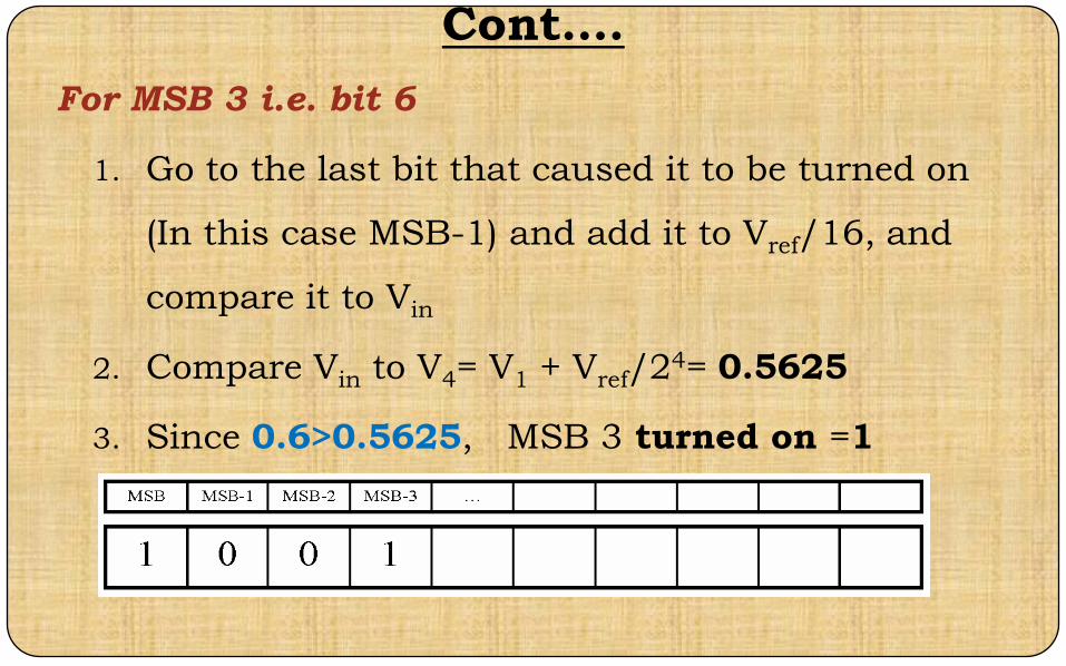
For MSB 3 i.e. bit 6
1. Go to the last bit that caused it to be turned on
(In this case MSB-1) and add it to Vref/16, and
compare it to Vin
2. Compare Vin to V4= V1 + Vref/24= 0.5625
3. Since 0.6>0.5625, MSB 3 turned on =1
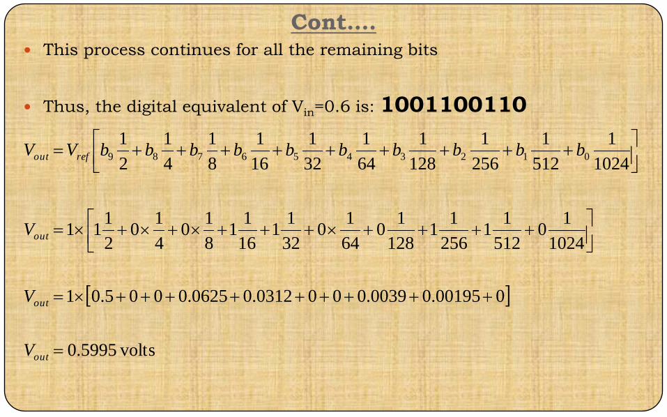
Cont…. This process continues for all the remaining bits
Thus, the digital equivalent of Vin=0.6 is: 1001100110
volts5995.0
000195.00039.0000312.00625.0005.01
1024
10
512
11
256
11
128
10
64
10
32
11
16
11
8
10
4
10
2
111
1024
1
512
1
256
1
128
1
64
1
32
1
16
1
8
1
4
1
2
10123456789
out
out
out
refout
V
V
V
bbbbbbbbbbVV
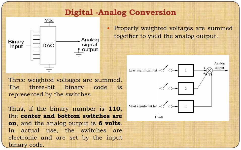
Digital -Analog Conversion
Properly weighted voltages are summed
together to yield the analog output.
Three weighted voltages are summed.
The three-bit binary code is
represented by the switches
Thus, if the binary number is 110,
the center and bottom switches are
on, and the analog output is 6 volts.
In actual use, the switches are
electronic and are set by the input
binary code.
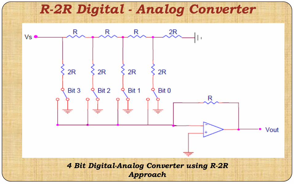
R-2R Digital - Analog Converter
4 Bit Digital-Analog Converter using R-2R
Approach
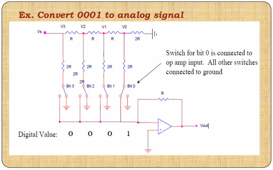
Ex. Convert 0001 to analog signal
Cont……

Cont……
=V1R/(2R) =
Cont……

Cont……
Cont……
Digital - Analog Converter
For binary input 1111, voltage V0 is then equal to:
In generic terms, for a four bit DAC, the equivalent
analog output is given by:
16
1
8
1
4
1
2
1sout VV
16
1
8
1
4
1
2
10123 bbbbVV sout

Example 1
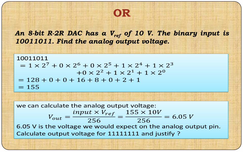
An 8-bit R-2R DAC has a Vref of 10 Volts. The binary input is
10011011. Find the analog output voltage.
volts0546.6
0039.000781.000312.00625.0005.010
256
11
128
11
64
10
32
11
16
11
8
10
4
10
2
1110
256
1
128
1
64
1
32
1
16
1
8
1
4
1
2
101234567
out
out
out
refout
V
V
V
bbbbbbbbVV
OR
An 8-bit R-2R DAC has a Vref of 10 V. The binary input is
10011011. Find the analog output voltage.

Op amplifier
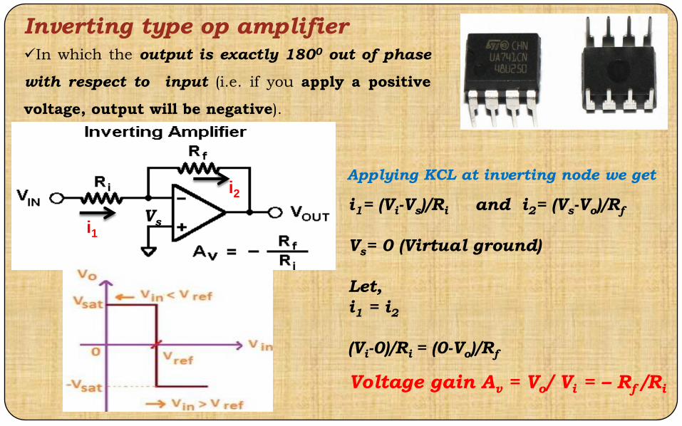
Inverting type op amplifierIn which the output is exactly 1800 out of phase
with respect to input (i.e. if you apply a positive
voltage, output will be negative).
Applying KCL at inverting node we get
i1= (Vi-Vs)/Ri and i2= (Vs-Vo)/Rf
Vs= 0 (Virtual ground)
Let,
i1 = i2
(Vi-0)/Ri = (0-Vo)/Rf
Voltage gain Av = Vo/ Vi = – Rf /Ri
i1
i2
Vs

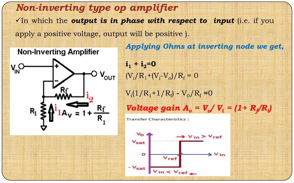
Non-inverting type op amplifier
In which the output is in phase with respect to input (i.e. if you
apply a positive voltage, output will be positive ).
Applying Ohms at inverting node we get,
i1 + i2=0
(Vi/R1+(Vi-Vo)/Rf = 0
Vi(1/R1+1/Rf) - V0/Rf =0
Voltage gain Av = Vo/ Vi = (1+ Rf/Ri)