Embed Size (px)
Citation preview

1
MECT411 Capstone Team Project
Eastern Mediterranean University
Faculty of Engineering
Department of Mechanical Engineering
Designing and Manufacturing 3D Printer
Course Coordinator
Assist. Prof. Dr. Mostafa Ranjbar
Supervisor:
Assist. Prof. Dr. Davut Solyalı
Team Members:
Mustafa Altabshi 137944
Louai Mikawi 127340
Massa Alsafadi 149110
Capstone Team Project 2015-2016

2
ABSTRACT
Due to the problems caused by the complex parts production by traditional machining
such as lack of quality and the need of plenty time for production process, the industry has turned
to produce parts by 3D printer. The main purpose of this report is to investigate and explain the
concepts of a 3D printer that increase the quality of production and reduce the time needed for
the manufacturing process. First, the report discusses the increasing demands on production and
manufacturing, and the 3D machines as a solution to compensate these demands. Some of 3D
machines types and the characteristics of each one will be listed. Then it focuses on 3D printer
types and how do they function. It shows also the applied fundamental concepts of Arduino,
stepper motor and cartridge heater. After that it illustrates in details how to design and
manufacture 3D printer from all aspects whether mechanical or electrical and even software, and
clarify how to link between mechanical and electrical parts to work together. Finally at the end
of the report a shown diagrams and calculations are explained. In addition, the manufacturing
process of the mechanical components and the connecting of the electrical circuit will be
illustrated. Finally, the assembly of the whole prototype, testing it and discussing its results will
be clarified.
Keywords: 3D printer, 3D machines, manufacturing products, Arduino, stepper motor, cartridge
heater, mechanical and electrical combination.

3
Table of Contents ABSTRACT ................................................................................................................................ 2
CHAPTER 1 ............................................................................................................................. 10
INTRODUCTION .................................................................................................................... 10
1.1 Why 3D machines? ........................................................................................................ 11
1.2 Types of 3D Machines ................................................................................................... 11
1.2.1 - CNC Machines .............................................................................................................. 11
1.2.2 - 3D Printers ..................................................................................................................... 12
1.3 Objective of the Project ................................................................................................. 13
1.4 Organization of the Report............................................................................................. 13
CHAPTER 2 ............................................................................................................................. 15
Literature review ....................................................................................................................... 15
2.1 History of 3D Printer .......................................................................................................... 15
2.2 Purpose of 3D Printer.......................................................................................................... 16
2.3 Types of 3D Printers ........................................................................................................... 17
2.3.1 Extrusion .......................................................................................................................... 17
2.3.2 Light Polymerized ............................................................................................................ 19
2.3.3 Powder Bed ...................................................................................................................... 21
2.3.4 Laminated ........................................................................................................................ 22
2.3.5 Wire.................................................................................................................................. 22
2.4 The Chosen Type of 3D Printers ........................................................................................ 23
CHAPTER 3 ............................................................................................................................. 24
DESIGN AND MANUFACTURING ...................................................................................... 24
3.1 Prototype Components ........................................................................................................ 24
3.1.1 Arduino Mega 2560 ......................................................................................................... 24
3.1.2 Stepper Motor .................................................................................................................. 25
3.1.3 Stepper Driver .................................................................................................................. 29
3.1.4 Extruder............................................................................................................................ 31
3.1.4.1 Cartridge Heater ............................................................................................................ 31
3.1.4.2 NTC Thermistors .......................................................................................................... 32

4
3.1.4.3 Nozzle ........................................................................................................................... 33
3.1.5 PTFE Tubing .................................................................................................................... 34
3.1.6 End Stops ......................................................................................................................... 34
3.1.7 Ramp 1.4 .......................................................................................................................... 35
3.1.8 Graphical LCD ................................................................................................................. 36
3.1.9 Fan.................................................................................................................................... 36
3.1.10 Bearing ........................................................................................................................... 36
3.1.10.1 Linear Bearing ............................................................................................................ 37
3.1.10.2 608 Bearing ................................................................................................................. 37
3.1.11 Rods ............................................................................................................................... 37
3.1.11.1 Linear Rods ................................................................................................................. 37
3.1.11.2 Threaded Rods ............................................................................................................ 37
3.1.12 Pneumatic Quick Release Fittings ................................................................................. 38
3.1.13 Timing Pulley................................................................................................................. 39
3.1.14 Timing Belt .................................................................................................................... 39
3.1.15 Braided Cable Sleeving.................................................................................................. 40
3.1.16 Nuts ................................................................................................................................ 40
3.1.17 Bolts ............................................................................................................................... 40
3.1.18 Set Screws ...................................................................................................................... 40
3.1.19 Aluminum for Extruder and Brackets ............................................................................ 40
3.2 Material Selection ............................................................................................................... 41
3.2.1 Filament ........................................................................................................................... 41
3.2.2 Plywood ........................................................................................................................... 41
3.2.3 Aluminum ........................................................................................................................ 42
3.3 Calculations......................................................................................................................... 42
3.3.1 Motor Selection ................................................................................................................ 42
3.3.2 Cartridge Heater ............................................................................................................... 42
3.3.3 Thermistor ........................................................................................................................ 42
3.3.4 Belt Calculations .............................................................................................................. 44
3.3.5 Power Screw Calculations ............................................................................................... 47
3.3.6 Shafts and Guiding Rods ................................................................................................. 49

5
3.3.7 PID Controller for The Extruder’s Heater ....................................................................... 49
3.4 Electrical Circut .................................................................................................................. 52
3.5 Theoretical Results.............................................................................................................. 52
3.6 Designing by SolidWorks ................................................................................................... 59
3.7 Interfacing ........................................................................................................................... 60
3.8 Programing .......................................................................................................................... 61
3.9 Slicing process .................................................................................................................... 62
3.10 Software ............................................................................................................................ 63
3.11 Manufacturing ................................................................................................................... 63
3.12 Assembling ....................................................................................................................... 64
3.13 Cost Analysis and Suppliers List ...................................................................................... 64
CHAPTER 4 ............................................................................................................................. 69
MANUFACTURING AND ASSEMBLY ............................................................................... 69
4.1 Manufacturing ..................................................................................................................... 69
4.1.1 Wooden Box .................................................................................................................... 69
4.1.2 Plastic Supporters............................................................................................................. 71
4.1.3 Wooden Supporters .......................................................................................................... 71
4.1.4 Managing the Belts .......................................................................................................... 72
4.1.5 Extruder............................................................................................................................ 73
4.1.6 Aluminum plate ............................................................................................................... 75
4.1.7 Shafts................................................................................................................................ 79
4.2 Assembly............................................................................................................................. 77
CHAPTER 5 ............................................................................................................................. 79
RESULTS AND DISCUSSIONS ............................................................................................. 79
5.1 Testing of Final Project ....................................................................................................... 79
5.2 Discussion of Results .......................................................................................................... 81
5.3 Technical Difficulties.......................................................................................................... 81
CHAPTER 6 ............................................................................................................................. 83
FUTURE WORKS & CONCLUSION ..................................................................................... 83
6.1 Future Works ...................................................................................................................... 83
6.2 Conclusion .......................................................................................................................... 83

6
REFERENCES ......................................................................................................................... 84
APPENDICES .......................................................................................................................... 86
APPENDIX A - LOGBOOK .................................................................................................... 87
APPENDIX B - GANTT CHART ............................................................................................ 95
APPENDIX C - DRAWINGS .................................................................................................. 96
APPENDIX D – ENGINEERING STANDARDS ................................................................. 134
APPENDIX E - MANUFACTURING PHOTOS .................................................................. 136

7
List of Figures
Figure 2.1 Growth in 3D printer products……………………………….………………………17
Figure 2.2 The block diagram of 3D printing process………………….………………………..18
Figure 2.3 3D printing by extrusion method……………………………………….…………….19
Figure 2.4 3D printing by SLA technique…………………………………………...……….….20
Figure 2.5 3D printing by powder bed method……………………………………………….….22
Figure 3.1 Arduino Mega2560……………………………………….…………………………..26
Figure 3.2 The rotation of a stepper motor………………………………………….…………...29
Figure 3.3 A4988 DMOS Microstepping Driver……………………………………….………..30
Figure 3.4 Functional block diagram of A4988 DMOS Microstepping Driver……………....…31
Figure 3.5 Microstepping in the stepper motor……………………………………...…………...32
Figure 3.6 Cartridge heater………………………………………………………………………33
Figure 3.7 Characteristics of the Three Temperature sensors……………………………...…….34
Figure 3.8 Limit switch (end stop) for 3D printer…………………………………..…………...36
Figure 3.9 RAMP 1.4………………………………………………...…………………………..36
Figure 3.10 LCD Screen Menu Tree…………………………………………….……………….37
Figure 3.11 608 Bearings……………………………………………….………………………..38
Figure 3.12 Thread rods………………………………………………………….………………39
Figure 3.13 Pneumatic Quick Disconnect……………………………………………………….39
Figure 3.14 Timing belt pitch and pulley pitch…………………………………………….…….40
Figure 3.15 Nuts………………………………………….………………………………………41
Figure 3.16 Free body diagram………………………………………….……………………….43
Figure 3.17 Finding the length of the belt…………………………………………….………….46
Figure 3.18 Torque speed characteristic of the stepper motor used……………………………..47
Figure 3.19 Belt force analysis……………………….………………………………………….47
Figure 3.20 GT2 timing belt technical details…………………………………………………...48
Figure 3.21 Block diagram of the PID controller……………………………….……………….50

8
Figure 3.22 3D circuit of 3D printer….………………………………………………………….52
Figure 3.23 Schematic electrical circuit of 3D printer…………………………….…………......53
Figure 3.24 Final mechanical design of 3D printer……………………….……………………..59
Figure 3.25 Views of the SolidWorks drawing…………………………….……...…………….60
Figure 3-26 Some commands of Marlin firmware………………………………………………61
Figure 3-27 Another part of Marlin firmware……………………………………………………62
Figure 3.28 Slicing process………………………………….…………………………………...62
Figure 4.1 Box wooden ................................................................................................................. 70
Figure 4. 2 Cutting the wooden slices ........................................................................................... 70
Figure 4. 3 Two types of plastic supporters .................................................................................. 71
Figure 4. 4 Catching the belt by a plastic slice ............................................................................. 72
Figure 4. 5 Shaping the extruder ................................................................................................... 73
Figure 4. 6 Drilling the extruder ................................................................................................... 74
Figure 4. 7 The last design of the extruder ................................................................................... 75
Figure 4. 8 The Steel plate ............................................................................................................ 76
Figure 4. 9 Prototype after assembling ......................................................................................... 77
Figure 4. 10 The last prototype of the wooden box ...................................................................... 77
Figure 4. 11 Setting the components on the wooden base ............................................................ 78
Figure E- 1 Cutting the wooden slices……………………………………………….…………136
Figure E- 2 The final design of the wooden box……………………………………………….136
Figure E- 3 Shaping the extruder……………………………………………………………….137
Figure E- 4 Drilling the extruder……………………………………………………………….138
Figure E- 5 The final design of the extruder……………………………………………………138
Figure E- 6 Adjusting the shafts' lengths and diameters……………………………………….139
Figure E- 7 Testing the electrical circuit…………………………………………….…………139
Figure E- 8 Printing an object…………………………………………………………………140
Figure E- 9 Prototype after assembling…………………………………………………..…….140
Figure F- 1 3D Printer Poster…………………………………………………………………...142

9
List of Tables
Table 1 Cost Analysis and Suppliers List ..................................................................................................... 65
Table 2 Miscellaneous Costs ....................................................................................................................... 68

10
CHAPTER 1
INTRODUCTION
Since the Industrial Revolution has begun, the whole world became interested in industry
and its development. Many countries have allocated large budget for scientists and engineers to
develop industry in all respects and merge them with the latest technology to facilitate the
manufacturing process because of many reasons. Quality is the most important of these reasons,
because it contributes to reduce the life of production and accelerate its failure and breaking it
with corrosion factors such as rust. Also the time needed produce an object has been a major
reason because the manufacture of a simple piece needs a lot of time and passes through several
stages for its formation. On the other hand, when a large quantity of pieces is needed to be
manufactured , the number of workers will be increased or a lot of processing time will be
consumed. Engineers have discovered many improved designs and have added new devices from
time to time. 3D machines, for example, were founded to increase productivity with less time
and the highest efficiency and quality. It is capable of producing complex pieces during several
minutes only.
3D printer project 2; its purpose is to have the highest efficiency and lowest time for the
production process. The report will firstly explain in details how to design and manufacture a 3D
printer. Secondly, it will clarify components operation, how it work and how to install them.
Lastly, connecting the mechanical and electrical components together will be explained and
programming the Arduino to reach the main purpose of the project.
This project will be a good reference for mechanical, mechatronic and electrical
departments because it will show the combination between the mechanical and electrical work
during the machine operation.
The whole report will summarize the 3D printer construction, classification of 3D
printers, filament, cartridge heater, stepper motor and Arduino. And it will let the reader to be
familiar with these words in his/her carrier as a mechanical / mechatronic / electrical engineer.

11
1.1 Why 3D machines?
Manufacturing products is the main base for almost everything is used in everyday life by
using an enormous variety of methods. Each one depends on several factors including time
value, cost, quality, accuracy and complexity.
Few decades ago, people used to create their products manually and by using simple traditional
tools that were used to produce inaccurate low quality objects, which was consuming human's
energy, time and cost.
Thus, nowadays technology is taking the lead in everything that surrounds us including
manufacturing process. Therefore, new kinds of machines were invented in order to reduce the
lack of high performance, increase productivity and efficiency in the industrial field, and also to
cope with people's dramatically increasing demands. These machines are called 3D machines.
3D machines are from the most essential machines that are used recently to build 3D objects due
to many reasons. To begin with, their simplicity and complexity at the same time; complexity in
designing the machines in order to manufacture very high quality products, and simplicity in the
method of building different types of objects from different materials. Moreover, speed and less
time are required for designing and prototyping any object mainly because of using digital
devices during the process. In addition, these types of machines do not need expensive
equipment for the product construction, so it can be considered them economically efficient.
Nevertheless, the most important reason is that there is no excessive human involvement during
building the object which is considered to be a massive development in the history of
manufacturing.
1.2 Types of 3D Machines In this part of the first chapter types of 3D-machines are going to be talked about with
brief information about each one. The most famous and common used types in factory are CNC
machines and 3D printers.
1.2.1 - CNC Machines
CNC is an acronym for the first letters of "Computer Numerical Control". It’s a multi-
function mechanical machine that have tool box as (cutter, driller, miller) which can be

12
controlled manually or automatically by using a computer, nowadays most of them use a
computer to control it. CNC can build shapes in 3 axis (X, Y, Z), or more depending on the
application. This machine typically have a controller to give order to the electrical and
mechanical parts, some commands are given as a program language to the machine by codes
called (G-CODE) which is simple to be written by hand and generate it by training. Before the
G-CODE is applied, the code should be considered as correct, otherwise the machine will be
damaged if correct values aren't given to make tests. There are some programs on the
computers that can understand the codes which are applied, and it will draw a sample of the
shape that is wanted, in this case it will be sure about the design and at the same time it won't
damage the CNC machine which is very expensive. After sending the codes to the machine, it
will start to make the design. The computer changes the design by using Computer Aided Design
software (CAD), into numerical prototype. The numerical can be considered to be the
coordinates for the graph and they control with movement of the tool box.
Types of CNC:
1–Milling machine.
2– Lathes.
3- Plasma cutters.
4- Electric discharge machining.
5- Water jet cutters.
1.2.2 - 3D Printers
The world of industry also call it as" additive manufacturing (AM)"it’s a type of 3D
machines which has the ability to build 3D shapes by scanning a product by using a 3D- scanner
then transfer it by computer as dots and connect these dots by lines which totally will create a
complete geometry and change it as program language, or directly give the commands from
specific computer language or design program, so the design will be objected before it's built in
real.
3D-printers basically depend on melted materials to build the shapes, so different filament gives
different applications. Plastic filament is a common type or by using powder bed with inkjet
printer head. One type of 3D printers squirts out a stream of heated, semi-liquid plastic that will

13
become dry as the printer's head moves around of the shape to create the outline of each layer
within the object.
3D-printers became very important in life because it's used in many functions like building any
model shapes that are want. Moreover, in medicine it's used to make effective pills that make the
price of medicine cheaper because the production expense will decrease. Another example is a
machine that can build real houses automatically without any human control with great speed
and high accuracy.
1.3 Objective of the Project
Designing
The project needs a full design for all the pieces and assemble them to form our 3D printer,
and designing the external shape of it. In addition, conducting some tests on the design is
also needed to make sure that the printer will work without any problems.
Manufacturing
The external shape of the 3D printer will be manufactured by different machines which exist
in the workshop.
Installing the 3D printer
A full 3D printer will be installed by using Arduino, stepper motors and cartridge heater (all
will be mentioned and explained in details in the report) and the operation of these
components will be combined together through a programmed Arduino.
Programming
The Arduino will be programmed, tested and diagnosed to change the operation settings of
the stepper motors to get the highest efficiency, quality and minimum time. In addition, to
connect the 3D printer with simulation software before starting production.
1.4 Organization of the Report In chapter I 3D machines concept is briefly introduced and various types of these
machines (CNC machine, 3D printer) are mentioned and discussed too.
In chapter II a literature review will be introduced showing the history, previous works done and
the development of the 3D printer technologies. Also how to make a 3D printer and its functions

14
will be discussed. A brief review about types of 3D printers will be also listed. Finally, the type
of 3D printer that was chosen and the reason of choosing it will be mentioned.
In Chapter III, the designing and manufacturing of the prototype will discussed in details with
the components, materials and manufacturing plan. Modeling and analyzing results will be added
to compare with types of 3D printer.
In chapter IV manufacturing, assembling and testing processes will be illustrated.
In chapter V experimental results will be obtained and final results will be discussed.
Last chapter is about future works and conclusion.
This report will include appendices (Logbooks, Gant chart, Technical drawings, Engineering
standards and Manufacturing photos).
15
CHAPTER 2
Literature review
In this chapter old publication and researches will be surveyed, purpose of 3D printers
will be discussed and finally five types will be illustrated.
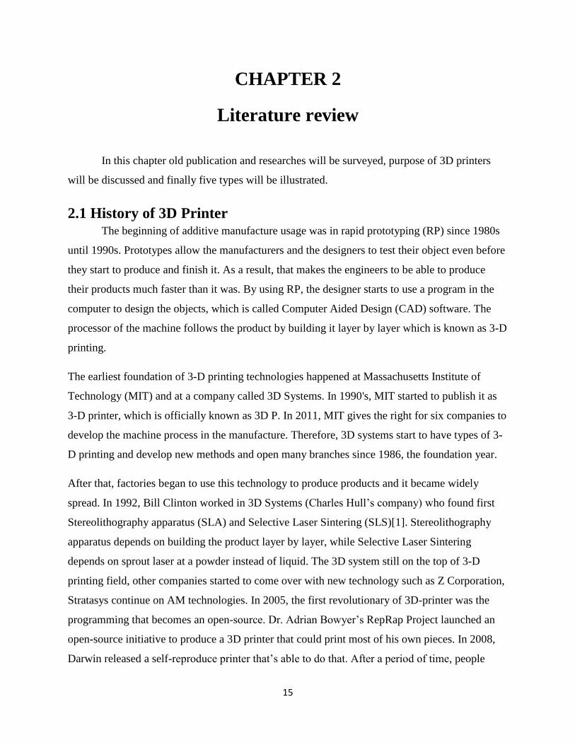
2.1 History of 3D Printer The beginning of additive manufacture usage was in rapid prototyping (RP) since 1980s
until 1990s. Prototypes allow the manufacturers and the designers to test their object even before
they start to produce and finish it. As a result, that makes the engineers to be able to produce
their products much faster than it was. By using RP, the designer starts to use a program in the
computer to design the objects, which is called Computer Aided Design (CAD) software. The
processor of the machine follows the product by building it layer by layer which is known as 3-D
printing.
The earliest foundation of 3-D printing technologies happened at Massachusetts Institute of
Technology (MIT) and at a company called 3D Systems. In 1990's, MIT started to publish it as
3-D printer, which is officially known as 3D P. In 2011, MIT gives the right for six companies to
develop the machine process in the manufacture. Therefore, 3D systems start to have types of 3-
D printing and develop new methods and open many branches since 1986, the foundation year.
After that, factories began to use this technology to produce products and it became widely
spread. In 1992, Bill Clinton worked in 3D Systems (Charles Hull’s company) who found first
Stereolithography apparatus (SLA) and Selective Laser Sintering (SLS)[1]. Stereolithography
apparatus depends on building the product layer by layer, while Selective Laser Sintering
depends on sprout laser at a powder instead of liquid. The 3D system still on the top of 3-D
printing field, other companies started to come over with new technology such as Z Corporation,
Stratasys continue on AM technologies. In 2005, the first revolutionary of 3D-printer was the
programming that becomes an open-source. Dr. Adrian Bowyer’s RepRap Project launched an
open-source initiative to produce a 3D printer that could print most of his own pieces. In 2008,
Darwin released a self-reproduce printer that’s able to do that. After a period of time, people

16
started writing their programs everywhere based on their various ideas, and share them around
the entire internet which makes it look like a game for technology lovers [2].
The technology has been improved a lot in many ways, such as the required time to print the
figure, the details of the product, and how much clean is the finishing when it's completed. The
material and equipment is getting cheaper and offer many types as plastic and ceramic and the
processes is going faster. Nowadays, the size of printing varies from small electronic device to
building homes or big real cars. The system of 3-D still new in the field of manufacture and still
needs more develop. However, this technology is better than the common process which is called
Computer Numerical Controlled (CNC) machine. CNC process is the opposite of AM because
CNC machines remove the Iron filings of the object while the AM build it by one line on the top
of the other.
Figure 2.1 shows the growth in 3D printer products in the last 10 years.
Figure 2.1 Growth in 3D printer products [3]
2.2 Purpose of 3D Printer 3D printing or as they are called additive manufacturing is a process of producing 3D
solid objects from a digital file. The manufacturing of a 3D printed product is accomplished by
using additive processes. First of all, a 3D CAD sketch is introduced to the 3D printing software,
17
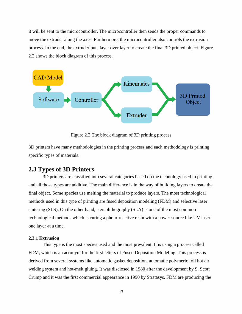
it will be sent to the microcontroller. The microcontroller then sends the proper commands to
move the extruder along the axes. Furthermore, the microcontroller also controls the extrusion
process. In the end, the extruder puts layer over layer to create the final 3D printed object. Figure
2.2 shows the block diagram of this process.
Figure 2.2 The block diagram of 3D printing process
3D printers have many methodologies in the printing process and each methodology is printing
specific types of materials.
2.3 Types of 3D Printers 3D printers are classified into several categories based on the technology used in printing
and all those types are additive. The main difference is in the way of building layers to create the
final object. Some species use melting the material to produce layers. The most technological
methods used in this type of printing are fused deposition modeling (FDM) and selective laser
sintering (SLS). On the other hand, stereolithography (SLA) is one of the most common
technological methods which is curing a photo-reactive resin with a power source like UV laser
one layer at a time.
2.3.1 Extrusion
This type is the most species used and the most prevalent. It is using a process called
FDM, which is an acronym for the first letters of Fused Deposition Modeling. This process is
derived from several systems like automatic gasket deposition, automatic polymeric foil hot air
welding system and hot-melt gluing. It was disclosed in 1980 after the development by S. Scott
Crump and it was the first commercial appearance in 1990 by Stratasys. FDM are producing the

18
parts by extruding small materials which have sclerosis property that is quick to be formed of
layers successfully. Metal wire and thermoplastic filament are examples for the materials used
and has the required properties.
FDM used diverse polymers among them, high density polyethylene (HDPE), acrylonitrile
butadiene styrene (ABS), polylactic acid (PLA), polycarbonate (PC), polyphenylsulfone (PPSU),
high impact polystyrene (HIPS) and PC / ABS. These polymers are made from virgin resins in
the form of filaments.
In the extrusion process, the plastic rod is fed to the extruder through a motor and gears. The
plastic moves between the two gears and enters the extruder’s nozzle. Then the plastic is melted
by a heater that is fixed around the nozzle. The melted plastic will exit the nozzle through a small
opening of a diameter of 2-6 mm. Also a fan that is attached to the extruder will cool down the
plastic on the printing plate. The speed of flow and movement of the head of extrusion are
adjusted by stepper motors or servo motors. Extrusion process in this type of 3D printers is
passed through cold end and hot end. Figure 2.3 shows the process of 3D printing by extrusion
method.
Figure 2.3 3D printing by extrusion method [4]

19
Each type has advantages and disadvantages but the most prominent of disadvantages of this
type of 3D printers is the inability to manufacture structures for several reasons, including that it
will not be supported during the building process. In addition, the support which is designing
within the structure will be breaking during the finishing process because of the thin of support.
On the other hand, among the most prominent of its advantages is it used for the manufacture of
large-size industrial objects also it used in a lot of different desktop models.
2.3.2 Light Polymerized
In 1986, stereolithography (SLA) was invented by Chuck Hull who is the founder of the
largest and most successful 3D printers company called 3D Systems. SLA based on the use of
photopolymerization to manufacture solid objects from liquid materials. This process reached
from several studies, such as photosculpture which was found by François Willème in 1860 and
photopolymerization which have been uncovered by Mitsubishi's Matsubara in 1974. In 1987,
the first SLA machine was sold and it is still the main element of 3D printing since that date.
Figure 2.4 shows the process of 3D printing by SLA technique.
Figure 2.4 3D printing by SLA technique [5]

20
Photosculpture method is based on taking a group of pictures for the body from different angles
so that they are equal in dimension. After that, projecting each photograph on the screen is done.
The modeling clay is tracking the outline which got it from the photograph. In photo-
polymerization, lighting controls the liquid polymer which includes chromophores, this
controlling must be under safelight conditions. As a result, a hardening of the liquid polymer is
resulted. Otherwise, added molecules are used to interact with the solution to begin
polymerization process with the knowledge that these molecules have the photosensitive.
In polymerization, StereoLithography Apparatus (SLA) is the beginning of everything and it is
considered the basis of 3D printing. The laser beam which is used for SLA is like that is using in
SLS machine but it differs in one point, it will not melt the powder because it has not a powerful
property. In addition, it uses a special plastic so that means it remains liquid until it is exposed to
light like ultraviolet light. The chemical property will change the covalent bonds which are
resulting from polymerization monomers because it is exposed to light. In the beginning, it
builds a plate then starts to move down with simple spaces to shine the light to the polymer
liquid again. It repeats this process until the object is fully manufactured. Finally, the liquid
polymer is dried after all that. This process has been completed with manufacturing solid model.
The advantage of this type is the ability to manufacture a very small object and has a very fine
features using 3D micro-fabrication technique which are used in multiphoton
photopolymerisation. This method uses a beam of light and focuses it to follow 3D object which
is surrounded by a block of gel. In addition, this approach has the ability to manufacture features
sizes less than 100 nm with ease and without any problems. Also, it has the ability to
manufacture complex structures and interlocking objects.
There is another approach based on the use of synthetic resins. This technique is used to produce
objects consisting of several materials with different rates. In systems research is launching beam
of light from the bottom, and this allows for the spread of the resin in a thin and uniform layers.
As a result of this method it can underestimate the manufacturing time dramatically. Objet
Connex is an example that uses this approach and is commercially available.

21
2.3.3 Powder Bed
It is a famous manufacturing process. In 1993, this technology was earlier developed at
the Massachusetts Institute of Technology (MTV). After that Z Corporation obtained an
exclusive license Powder bed and inkjet 3D printing in 1995, known by several names like 3D
printing (3DP), binder jetting and drop-on-powder is a type of rapid prototyping and additive
manufacturing which are known as layered manufacturing technology to produce objects from
digital data which it describes. In addition, this technology of manufacturing includes Selective
Laser Melting and Selective Laser Sintering.
The idea of this process based on layered manufacturing technology. The product depends on
many thin cross sections finishing with 3D model. So the head of the machine moves during a
bed of powder metal, by spread an especial liquid binding material. A thin layer is spread on
complete section of the layer and start again on top of it until the product is complete. Unbound
powder is attaching layer by manually or automatically operation to remove the extra parts and
this process is called "de-powdering" and the removed parts can be used again for another
product. Figure 2.5 shows the process of 3D printing by powder bed method.
Figure 2.5 3D printing by powder bed method [4]

22
2.3.4 Laminated
Laminated object manufacturing (LOM) is considered as a fast process. It comes to
produce the product faster than the bed-powder and it is developed by Helisys Inc. It could use
many materials in the same process. The adhesive- plastic, paper successively fixed together and
cut to final shape by laser or sharp material.
The object can be re-shaped after it's printed by machines as drilling or milling, the material
feedstock defines the process and usually this process is used to re-range the thickness.
Laminated object manufacturing is composed of eight sections which are foil supply, heated
roller, laser beam, scanning prism, laser unit, layers, moving platform and wastes. It consists of
several sequential operations and complementary to each other. The process is prolonged
application as follows. Firstly, sheet is adhered to a substrate with a heated roller. Secondly, laser
traces desired dimensions of pattern. Thirdly, laser cross hatches non-part area to facilitate waste
removal. Next, dais with completed layer moves down out of the way. After that, the material is
rolled into position. Then, the platform goes down to a new position to hold next layer. Finally,
the process is repeated again [6].
Each process has advantages and disadvantages, but the most important advantages of this type
is the cheap price due to readily available raw material and the possibility of producing large
parts because no chemical reaction is necessary. On the other hand, dimensional accuracy is
inconsiderable less than selective laser sintering and stereolithography but no milling step is
necessary.
2.3.5 Wire
Build near-net-shape parts are considered as type of an additive manufacturing process
which is Electron Beam Freeform Fabrication (EBF3). This process needs raw materials less
than other processes. In addition, it is different from that trademark with finish machining. The
working principle of EBF3 is building a metallic object directly from CAD, then the object is
divided to numerically sliced into layer. After that, it can be used to post-process program to
write a G-CODE to define the layer path and parameter for the EBF3 equipment. This type uses
focused beam of the electron in a vacuum environment. As a result it is creating a molten pool on
a substrate of metal. This beam is directed on the surface of the substrate while the molten pool
is fed by metal wire. The deposit solidifies rapidly after the electron beam crosses it; the part will
23
be strengthened enough to support itself. The process will repeat until it makes our needs shape.
The size is limited and the extra wire could be used it again "feedstock".
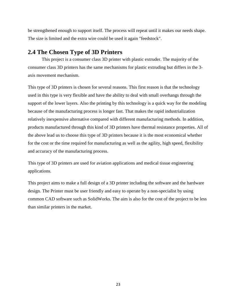
2.4 The Chosen Type of 3D Printers This project is a consumer class 3D printer with plastic extruder. The majority of the
consumer class 3D printers has the same mechanisms for plastic extruding but differs in the 3-
axis movement mechanism.
This type of 3D printers is chosen for several reasons. This first reason is that the technology
used in this type is very flexible and have the ability to deal with small overhangs through the
support of the lower layers. Also the printing by this technology is a quick way for the modeling
because of the manufacturing process is longer fast. That makes the rapid industrialization
relatively inexpensive alternative compared with different manufacturing methods. In addition,
products manufactured through this kind of 3D printers have thermal resistance properties. All of
the above lead us to choose this type of 3D printers because it is the most economical whether
for the cost or the time required for manufacturing as well as the agility, high speed, flexibility
and accuracy of the manufacturing process.
This type of 3D printers are used for aviation applications and medical tissue engineering
applications.
This project aims to make a full design of a 3D printer including the software and the hardware
design. The Printer must be user friendly and easy to operate by a non-specialist by using
common CAD software such as SolidWorks. The aim is also for the cost of the project to be less
than similar printers in the market.
24
CHAPTER 3
DESIGN AND MANUFACTURING
In this chapter the components of the project will be listed, suitable material will be
selected according to the parameters of each part of the project, the related equations and
calculations will be carried, and finally cost analysis of the project will be presented.
3.1 Prototype Components Every system consists of several components, choosing the suitable component is crucial
in any system and it should be chosen carefully in order to assure the proper operation of the
system. The prototype of 3D printer consists of several components. The design itself is simple
and easy to be manufactured and analyzed. This project is made of different components that
include mechanical, electrical and controller. Some components are interfaced digitally for
example drivers of the stepper motors and the LCD controller. Other components need analog
interfacing like fans, thermistor and the extruder heater. In this section, the system's components
will be discussed in details.
3.1.1 Arduino Mega 2560
Arduino is a little smart mind, which is called microcontroller or microprocessor,
these controllers have different inputs and outputs, and are able to control the machines in an
efficient way. PIC microcontrollers, Arduino, and programmable logic controls (PLC’s) are
some types of controllers, which are able to control any system with high efficiency and fast
processing. Here, the Arduino will be introduce controllers; introduction to Arduino, types of
Arduino, and interfacing with Arduino.
Atmega processor is a tool for making computers that can sense and control more of the
physical world than your PC. It is an open source physical computing platform based on a simple
microcontroller board and expansion environment for writing any program for the board. The
Arduino Mega uses the Atmega chip as the controller, so basically they are the same thing except
that the Arduino Mega has a complete board while the Atmega is only a chip that needs to be
connected to breadboard or any other board. Arduino Mega can be used to increase interactive

25
objects, taking inputs from a variety of motors, sensors, controlling devices, a variety of lights,
and other physical outputs. Arduino projects can be worked alone or communicate with a
running software on your computer e.g. Flash.
Arduino has programming language which is an implementation of wiring. It is a similar
physical computing platform because it depends on the processing environment of multimedia
programming.
There are many models of Arduino with different sizes, colors, and form factors, such as
Arduino Mega2560, Arduino Uno, Arduino Mini, and Arduino Nano. The best choice for our
project is Arduino Mega2560, because it has 256 KB of memory which is 8 times more than the
Uno also it has 54 input and output pins, 16 of them are analog pins. Figure 3.1 is showing
Arduino Mega2560 that is used in the project [7].
Figure 3.1 Arduino Mega2560
3.1.2 Stepper Motor
A basic function in a 3D printer is the movement of the three axes(X, Y and Z) for
manufacturing the product. In order to have the rotating and linear movements of those axes,
motors are needed to convert the electrical input into a mechanical movement for creating the
object to be built. These movements must be very precise, controllable and operate at different
speeds.

26
There are many different kinds of motors that provide linear and rotation movement but
our motors must be suitable to the printer's requirements, such as running on a low power rating
because there isn’t much resistive torque needed. The motors should also be easily controlled
and move with synchronization between them by a simple digital circuit. In addition, they must
move to exact and accurate locations step by step with minimum error.
But first, some types of DC motors will be mentioned as long as they have characteristics
of precision, easy controllability and discrete in order to know the difference among them and
take the best one that fits the printer’s needs.
Types of motors:
Brushed DC motor:
A brushed DC motor is the ordinary motor that is used in most of the applications. Its
main parts are an armature which acts as an electromagnet with two poles, a rotor which is the
permanent magnet, a commutator and the brushes that are connected to the commutator. When
the windings are charged, the rotor starts rotating causing the commutator to reverse the direction
of the current twice every turn, then changing the polarity to the permanent magnet, so the
armature keeps rotating. This DC motor has pros such as low cost, simplicity and can be
available in different sizes. It also has cons like short life due to the brushes, it produces noise,
and it’s difficult to control it precisely and can be useless in robots as they produce the slightest
torque.
Brushless DC motor:
A brushless DC motor is similar to the brushed one but it doesn't contain brushes. The
prime feature of the brushless motor is that it consists of a rotor as a permanent magnet and a
stator as an electromagnet. To follow the change in current orientation and measure the magnets
position, these motors use Hall Effect sensors. On one hand brushless motors are efficient in high
velocity applications, can produce more power and don't produce noise. On the other hand, they
are expensive because of their sophisticated design and need controllers in order to control their
speed.

27
Linear motor:
A linear motor has a structure that is almost similar to a brushless DC motor. It is a motor
that works in a linear movement instead of rotation, so it doesn't produce any torque. Therefore,
it's impossible to use it in application that has rotation movement.
Servo motor:
A servo motor is a combination of a DC motor, gears, control circuit and a position
sensor. It uses servomechanism in its performance that means using an encoder for position and
motion feedback to control the speed and final position. The position of servo motors in a
classical DC motor, can't be controlled more precisely than in a servo motor. PWM (Pulse-
Width-Modulation) is used for the control signal of servo motors. However, the position is
determined by the duration of the positive pulse, rather than speed of the servo shaft. A neutral
pulse value depends on the servo (most of the time will be about 1.5ms) keeps the servo shaft in
the center position. If that pulse value is increased, the servo will turn clockwise, and a shorter
pulse will turn the shaft anticlockwise. The servo control pulse is repeated every 20 milliseconds,
to send commands to the servo to know where to go, even if that means remaining in the same
position. Although servo motors are very accurate, quite small for simple applications and have a
high torque, they are unsuitable for the 3D printer, because it's difficult to use it in continuous
rotation as long as they move to certain angles [8].
Stepper motors:
A stepper motor is a brushless, synchronous motor with a special characteristic which is
simple positioning control, and moving in discrete steps by dividing a full rotation into a number
of steps. They have several coils that are organized in groups called "phases", by energizing each
phase the rotor will rotate step by step with a specific angle as it's shown in Figure 3.2; this
rotation angle is proportional to the input pulse of the motor. Therefore, for controlling the speed
and the position of the steps, a computer is evolved, which is a unique feature for using a stepper
motor to gain a very precise motion in its applications. In addition, microstepping is a unique
technology in the stepper motor which is control the current in the motor winding to a degree
that divides the number of positions between its poles, so that it lets the motor to move smoothly

28
and accurately. The stepper motor has three main types: variable-reluctance, permanent-magnet,
and hybrid [8].
Figure 3.2 The rotation of a stepper motor
From the previous study of DC motors, it is concluded that the most convenient motor for
printing 3D objects is the stepper motor because of these reasons:
• Stepper motors can contain a "home" switch or other element for keeping the
motion at high range of stability.
• Excellent position accuracy is obtained.
• If the windings are energized, the motor has full torque when it's not moving.
• No errors are accumulated from one step to the next.
• Very good responding to start-stop-reverse commands.
• Long life because of the brushes absence.
• Its response to the input pulses provides an open-loop control, helping the motor
to work easier and inexpensive to control.

29
• A large range of rotational velocities can be controlled as the velocity is
proportional to the frequency of the input pulses [9].
3.1.3 Stepper Driver
As long as the Arduino can't provide enough power to permit the motors to work directly,
a chip that is connected to it is used called stepper driver, which acts as a bus between the motor
and the Arduino for controlling the motion of the stepper motor. The most fundamental function
of the stepper driver is helping the motor to move in microsteps by providing fractional steps.
This helps smooth out the movement of the stepper motor and not vibrating during the process.
Stepper drivers usually work by chopping up a supply voltage using an embedded PWM chip.
These chips need minor support circuitry.
The stepper driver is generally connected to three main wire interface:
• STEP pin where the controller pulses it to move the motor one step.
• DIR pin which is set to choose whether a step is a clockwise step or
counterclockwise step.
• GND pin [10].
The driver in Figure 3.3 is used in the project which is A4988 DMOS Microstepping Driver.
Figure 3.3 A4988 DMOS Microstepping Driver [11]

30
Figure 3.4 illustrates that functional block diagram of A4988 DMOS Microstepping Driver.
Figure 3.4 Functional block diagram of A4988 DMOS Microstepping Driver [12]
A4988 DMOS Microstepping Driver:
This is a driver designed to operate bipolar stepper motors in full-, half, quarter-, eighth-,
and sixteenth-step modes as shown in Figure 3.5. Its output drive capacity is up to 35V and ±2
A.
It has a built in translator. The translator is used to make the implementation of micro
stepping easier when a complex microprocessor is not available. It does not need phase sequence
tables, high frequency control lines, or complex interfaces to a program [13].
While the stepping operation is in process, the chopping control in the A4988
automatically selects the current decay modes which are two types: one is slow or the other is

31
mixed. The device is set at the beginning to a fast decay for a proportion of the fixed off-time,
and then it moves into a slow decay for the remaining of the off-time in the mixed decay mode.
Mixed decay current control results in reduced audible motor noise, high step accuracy, and less
power dissipation [14].
A circuitry that has internal synchronous rectification control makes the power
dissipation during PWM operation to be better. Internal circuit protection contains: under voltage
lockout (UVLO), crossover-current protection and thermal shutdown with hysteresis. Special
power-on sequencing is not required [9].
Figure 3.5 Microstepping in the stepper motor
3.1.4 Extruder
The extruder is the main part of the whole procedure; it’s a moving head that helps
creating the object from the plastic filament layer by –layer.
The hot end of the extruder consists of several parts which are:
3.1.4.1 Cartridge Heater
A cartridge heater is a joule heating element (electrical resistance) that is used in the
plastic heating process; it’s highly compacted and basically depends on the surface watt density
which can reach up to 50 W/cm². But in this 3D printer will not reach to that level.

32
In Figure 3.6, it's seen that it consists of an outer metal enclosure called a sheath
containing resistive wiring while electrical insulation separate between this wiring and the
sheath.
Figure 3.6 Cartridge heater
3.1.4.2 NTC Thermistors
For permitting the cartridge heater to work properly, a sensor is needed for the
temperature control as it’s an important factor that should be put between the heater and the
working surface of the part.
One of the most popular sensor types for cartridge heater applications are thermocouple,
Resistance Temperature Detectors (RTD) and thermistors.
A Thermistor is made of semiconductor material that is like a type of resistor used to
measure temperature changes, because the temperature change leads to the change of resistance.
It works in the range of (-40 ~ 150) °C with accuracy = ±0.35. It has two different types, Positive
thermal coefficient (PTC) an increase in resistance occurs with an increase in temperature,
whereas the negative ones (NTC) works inversely.
But for a 3D printer the most suitable one is NTC thermistors because of the following reasons:
• It’s used in these kinds of machines, unlike the PTC which is used in other
applications such as fuses.
• It is usually more accurate than a thermocouple, and the thermocouples can

33
handle higher temperatures and give small voltages.
• It typically measures limited temperature range, while RTDs are useful over
larger temperature ranges,
• It responds very rapidly to changes in temperature.
• Small in size compared to thermocouples.
The relationship between its resistance and the temperature is nonlinear. Furthermore, the
resistance changes negatively and sharply with any positive change in temperature. Figure 3.7
can explain the characteristics of RTD, thermocouple and thermistors. The sizes are chosen
based on engineering standard (see Appendix-D-Table D.10).
Figure 3.7 Characteristics of the Three Temperature sensors
3.1.4.3 Nozzle
After melting the plastic filament via the cartridge heater, the molten plastic will exit
from a small pipe called nozzle that is used to direct or modify the flow of the molten plastic
over the table in a prescribed geometry, and deposits a thin string of plastic.
It also has varying cross sectional areas and whenever the nozzle is smaller, it gives
smaller details and sharper corners. The sizes are chosen based on engineering standard (see
Appendix-D-Table D.11).

34
3.1.5 PTFE Tubing
PTFE (polytetrafluoroethylene) tube is a tube that is used for the plastic string to enter
through it before melting it and after it. It has very excellent properties such as:
• Non-stick properties.
• Temperature resistance is possible that up to 260º C.
• Aging resistance.
• Low permeability.
• Superior chemical resistivity and low coefficient of friction.
• Mechanical resistance under severe conditions.
3.1.6 End Stops
For controlling the motion of the parts in the 3D printer an end stop switch as it's seen in
figure is used, which is a switch controlled by the motion of a machine part or existence of an
object.
While building the object, the stepper motors shouldn’t move continuously, they have to
stop at certain points to draw the exact figure accurately. Because of this, the limit switch is used
as an interlock, which is an electromechanical device that consists of an actuator connected to a
set of contacts mechanically. When an object comes to the end of its motion, the device operates
the contacts to break the electrical circuit, then the motor stops moving.
In this printer, four limit switches are used on the x, y, and z axes.

35
A sample of limit switch shown in Figure 3.8.
Figure 3.8 Limit switch (end stop) for 3D printer
3.1.7 RAMPS 1.4
It's an electronic device used with Arduino mega as a shield type it's used for many
functions related to motor so it has maximum of five stepper drivers to handle five stepper
motors. In our project, it is used for three reasons. Firstly, it handles more than one stepper motor
for different axis. Secondly, it has three MOSFET’S which used for fan and heater. Finally, the
cost is low if it's compared with ready circuit. Ass shown in the following Figure 3.9.
Figure 3.9 RAMPS 1.4

36
3.1.8 Graphical LCD
It's used as the feedback of the process and give us the information like (error,
temperature, etc...) as it's shown in Figure 3.10.
Figure 3.10 LCD Screen Menu Tree [15]
3.1.9 Fan
It's used for cooling for many reasons. Firstly, 3D printer produce high temperature
during the process because of that is needed to use system that can cool down the controller to
prevent from damage. Secondly, heating is occurred by the uneven cooling between outer of a
printed part and inner sections. The outside material will cool down and shrink faster than the
inside material if it's compared between them. This will cause the outside material to bend unlike
the hot material which won’t.
3.1.10 Bearing
To decrease the friction and make the motor move faster and better bearings will be used.
There are many kinds of bearings but linear bearings and ball bearings will be used for the
project and they were selected depending on the desired requirements.
37
3.1.10.1 Linear Bearing
It is designed to make movement frictionless in one direction.
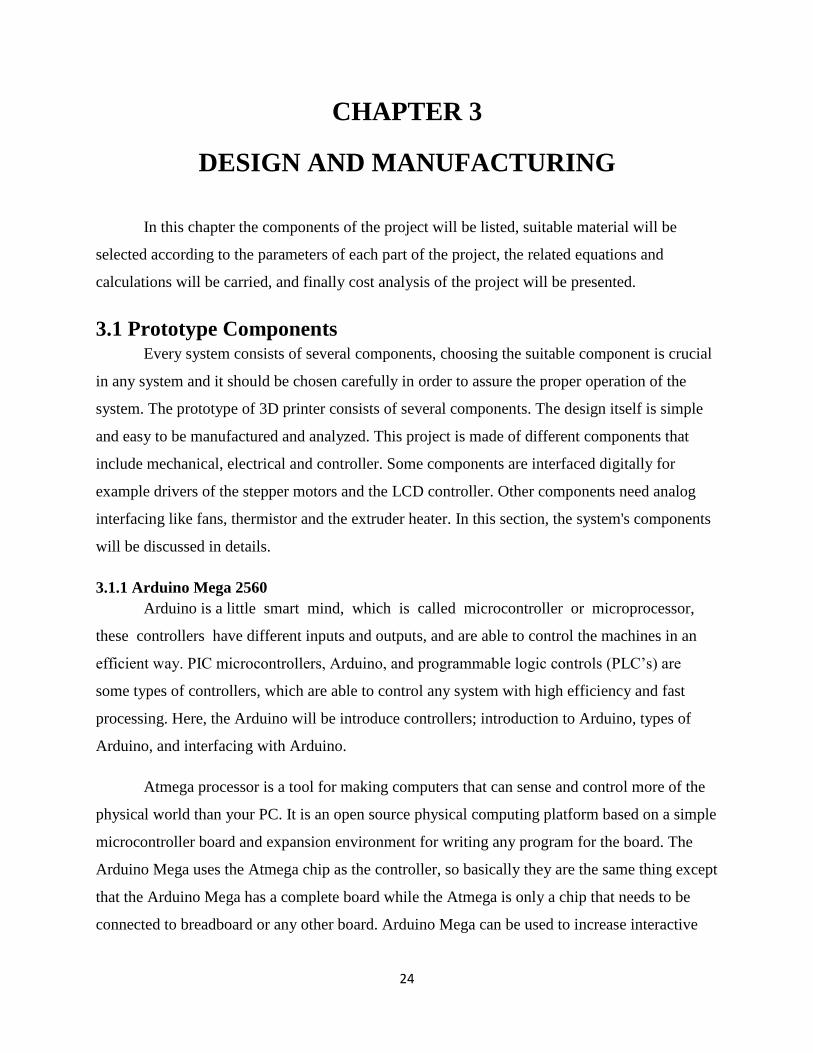
3.1.10.2 Ball Bearing
Generally they use the bearing to reduce the friction between two parts connected, so it
allows the rotation and linear motion to work properly. In our project it's used between the shaft
and the object which holds the shaft inside it. The following Figure 3.11 shows the design of
608 bearing.
Figure 3.11 608 Bearings
3.1.11 Rods
It’s a mechanism to connect the parts or to be as a transmission where the rods are usually made
from steel or aluminum and there are two common types. Linear Rods, Threaded Rods.
3.1.11.1 Linear Rods
It is a steel metal and looks like a shaft shape; it's used to hold the extruder and makes
move it easily to the three axes X, Y, Z. Steel is used because it's strong enough to carry the
printed parts and the table, it's also available everywhere. The sizes will be chosen based on
engineering standard (see Appendix-D-Table D.9).
3.1.11.2 Threaded Rods
It is a long shaft used in 3D printer to hold the plate where it's threaded all and usually
they use it in tension.

38
In this Figure 3.12 thread rod is shown. The sizes will be chosen based on
DIN 975-1986 (see Appendix-D-Table D.4).
Figure 3.12 Thread rods
3.1.12 Pneumatic Quick Release Fittings
Generally it's used to connect two parts as fluid easily. It could be used as assembly part
and if the tool is changed as shown in Figure 3.13, i.e. It's used to connect PTFE tubing in the
project so it's used to protect the plastic filament when it's inside it.
Figure 3.13 Pneumatic Quick Disconnect

39
3.1.13 Timing Pulley
Timing belts transmit torque and motion from a driving to a driven pulley. The main
purpose of the timing belts in the 3D printer is to convert the motion of the motor from rotary to
linear of the sliders synchronously and with very high precision. During operation, when the belt
is under load, a difference of tensions of the belt on the entering and leaving sides of the pulley is
developed. This is called effective tension 𝑇𝑒, and it represents the force transmitted between the
driver pulley and the belt. At the driver pulley effective tension is generated. The generated
tension is the actual working force that overcomes the load and overall resistance to the belt
motion [16]. The sizes will be chosen based on ISO (see Appendix-D-Table D.6).
3.1.14 Timing Belt
First of all, should be specified pitch 𝑝 of timing belt as shown in the Figure 3.14 below;
belt pitch is known as the distance between the centerlines of two close teeth and is measured at
the belt pitch line. On another hand, pulley pitch is measured on the pitch circle, it is known as
the arc length between the centerlines of two contiguous pulley grooves. Pitch circle corresponds
with the pitch line of the belt while the belt is rolled around the pulley. The one which is used in
our project is GT2 Timing Belt.GT2 Belt have a special profile with rounded teeth which reduces
slippage, it is very suitable for precision applications such that 3D printers and CNC machines
[16]. The sizes will be chosen based on DIN/ ISO 10823 (see Appendix-D-Table D.8).
Figure 3.14 Timing belt pitch and pulley pitch [17]

40
3.1.15 Braided Cable Sleeving
Use this component by covering the cables to protect them from scratch which leads to
cutting it. It will be exposed to heat after adjusting it to become not removable, that would give
the cable long life and more protection. The sizes will be chosen based on engineering standard
(see Appendix-D-Table D.7).
3.1.16 Nuts
A steel part inner threaded and it's usually used with thread rod to give the rod more strength and
stack it together as in the Figure 3.15 below. The sizes will be chosen based on ASMEANSI
B18.2.4.6M-2010 and DIN 439-1-1987 (see Appendix-D-Table D.2 and Table D.3).
Figure 3.15 Nuts
3.1.17 Bolts
Bolt is a sequence threaded used to join two parts by having the same diameter and have
inner threaded. It can be seen almost in every machine or mechanical designs. Steel bolt is used
because it has long life it also doesn’t become dusty and can be found easily in Cyprus. The sizes
will be chosen based on engineering standard (see Appendix-D-Table D.1).
3.1.18 Set Screws
It uses generally Power screw that will be used to lift the load of the printing table in addition to
protect the parts to resist the torque that will apply on it, generally it's used in gears. The sizes
will be chosen based on ISO 7434-1983 (see Appendix-D-Table D.5).
3.1.19 Aluminum for Extruder and Brackets
An aluminum part used for (90 degree) intersection to make the farm of 3D printer
becomes cubic shape.
41
3.2 Materials Selection Different materials are used in manufacturing the prototype, each part is made from
different materials than others. The material should be selected to fit the specifications and the
properties of each part of the prototype.
3.2.1 Filament There are different types of plastic that can be used for 3D printer. Each type of material
is used for specific applications based on material properties. Our project is based on the most
common types of plastics which are PLA and ABS. They are both thermoplastics that are
moldable and soft when heated. They can also be reprocessed and used once more.
There are three main criteria that the material used for printing must contain, first,
extrusion into plastic filament, second, extrusion and trace-binding through the process of 3D
printing, so in the end it's used in the application.
ABS is strong, flexible, and high temperature resistant. This makes it preferable for
professional applications. It is petroleum based, so when it's heated it has an undesirable smell.
To print using ABS a heated bed is required because it will warp when cooled.
PLA is a biodegradable plastic, with a wide range of colors and translucencies. It is plant
based that will give a sweet smell when heated unlike the ABS type. When the head of the
extruder is properly cooled, PLA has lower layer heights, sharper printed corners, and bigger
maximum printing speeds. PLA also does not need a cooler bed. Because of the previous
properties PLA is preferred for home printers and hobbyists.
3.2.2 Plywood It's a type of thin wood glued to each other to have the same thickness and shape and
usually it has 90 degree angel for boundary .It has many applications because it has high
flexibility, strength and low thickness. There are many types of Plywood deepens on the
application for example: Softwood plywood, Hardwood plywood, Tropical plywood, Aircraft
plywood, Decorative plywood (overlaid plywood), Flexible plywood and Marine plywood. In
our project Tropical Plywood will be used because it's strong enough and cheap comparing with
other types finally, it has high quality and density.

42
3.2.3 Aluminum Aluminum is one of the most important materials that trademark companies use it for
component structure. It can resist corrosion, can be recycled and has low density which makes
the product stronger and at the same time gives good looking, for example, it's used in most of
the smart phones nowadays. It will be used in our project because it has low weight which
doesn't make the printer work with high pressure on it; it also gives us strong frame transmission.
3.3 Calculations This section is about prototype studying and calculations by using the relative equations,
starting from studying motor selection, cartridge heater, thermistor, electrical circuit, belt and
power screw calculations, shafts and guiding rods and finally PID controller for the extruder’s
heater.
3.3.1 Motor Selection The stepper motors that are selected need some calculations that will allow them to work
properly.
The motor will be selected according to the needs of the Z-axis, which is most critical. The
selection of this motor will be used for the rest of the motors (X, Y-axis and feeder motor).
The rise torque to move a load up the thread is defined by the following Eqn. 1 and Figure 3.16
clarifies its parameters:
[
]
Where:
F is the Load to move [N].
Dp is the Pitch Diameter [m].
L is the lead [m/rev].
f is the friction coefficient.

43
Figure 3.16 Free body diagram
The force carried on the motor calculated through using Eqn. 2:
( )
The lowering torque is found from the Eqn. 3:
[
]
The electrical specifications for the motor are also needed. There are 2 critical parameters:
Amps per phase - This is the maximum current that the motor windings can handle
without overheating.
Resistance per phase - This is the resistance of each phase. A Voltage rating is often
stated [18].
That leads for using Ohm's law Eqn. 4:
In addition, the motor draws the highest current when the motor stops
3.3.2 Cartridge heater:
In the cartridge heater there is "Watt density" parameter that refers to the heat flow rate of
the cartridge heater. To calculate it, this Eqn. 5 is used:
Watt Density =

44
Where:
W= wattage (w)
D= diameter (mm)
HL = Heated Length (mm)
Watt Density W/mm.
3.3.3 Thermistor
The thermistor resistance-temperature relationship can be approximated by Eqn. 6,
Where:
T is temperature (in kelvin)
𝑇 is the reference temperature, usually at room temp (25 °C-298.15 K).
R is the resistance of the thermistor (ohm).
is the resistance at 𝑇 [19].
β is a calibration constant that depends on the thermistor material, usually it's between 3,000-
5,000 K.
The melting temperature of the PLA/PHA plastic filament should be set between 180 .
3.3.4 Belt Calculations Finding the length of the belt:
Here an example will be given, as shown below in Figure 3.17 that displays the
procedure
1- taking the both of the small and the large pulley and adding them
10+2=12
45
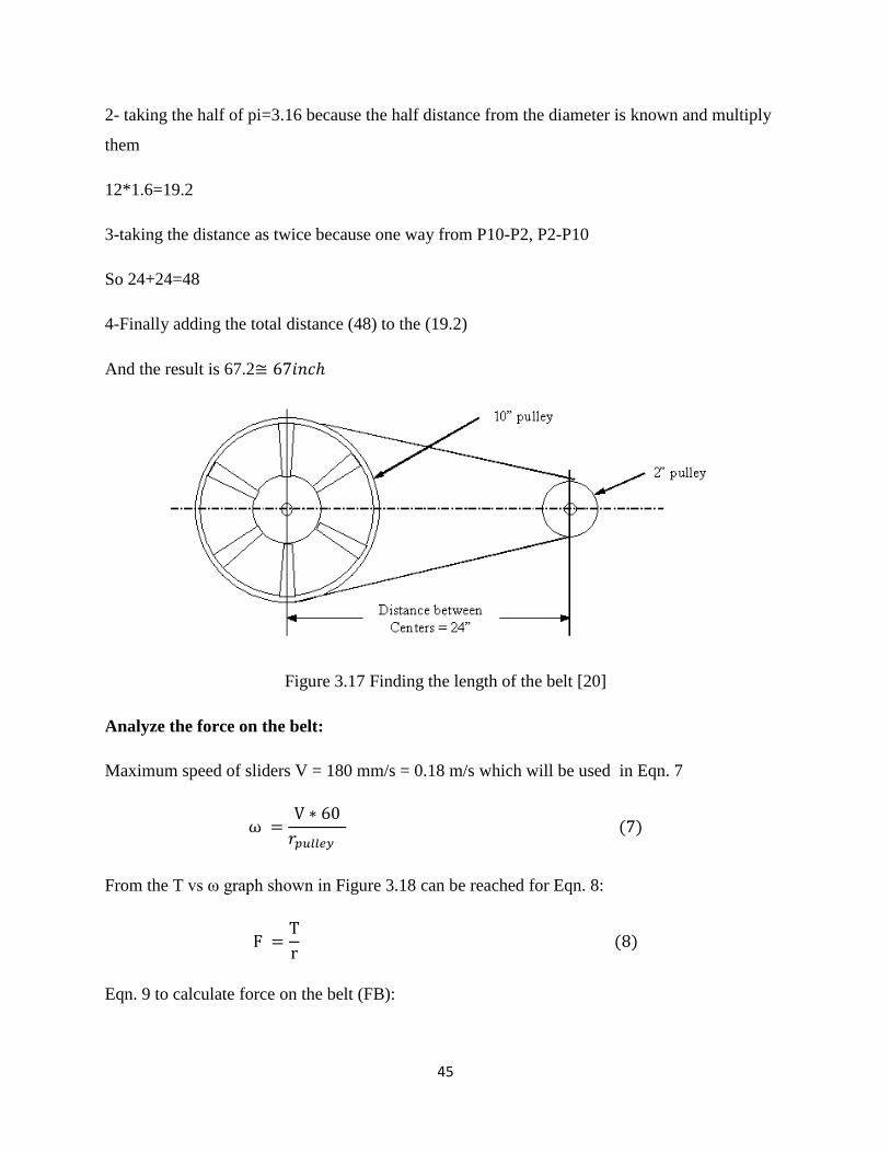
2- taking the half of pi=3.16 because the half distance from the diameter is known and multiply
them
12*1.6=19.2
3-taking the distance as twice because one way from P10-P2, P2-P10
So 24+24=48
4-Finally adding the total distance (48) to the (19.2)
And the result is 67.2
Figure 3.17 Finding the length of the belt [20]
Analyze the force on the belt:
Maximum speed of sliders V = 180 mm/s = 0.18 m/s which will be used in Eqn. 7
From the T vs ω graph shown in Figure 3.18 can be reached for Eqn. 8:
Eqn. 9 to calculate force on the belt (FB):

46
Figure 3.18 Torque speed characteristic of the stepper motor used
A presentation of belt force analysis is seen in Figure 3.19.
Figure 3.19 Belt force analysis

47
GT2 Belt is 2mm tooth pitch and 6mm wide. Moreover, there are pulleys designed to be used
with GT2 6mm wide belts and with the same pitch. From the datasheet [21], the Working tension
of this belt is 89 N. So, the GT2 Timing Belt is good for the application. Details are clarified in
Figure 3.20.
Figure 3.20 GT2 timing belt technical details
3.3.5 Power Screw Calculations The most available power screw is 𝑇8 𝑆𝑡𝑎 𝑙𝑒𝑠𝑠 𝑆𝑡𝑒𝑒𝑙 𝑝𝑜𝑤𝑒 , with M4x5mm it is
commonly used in 3D printers and very suitable for precise applications. For power screw
design, it should be specified how much torque will be applied to the nut of the screw to
overcome the friction forces and the force caused by the table and the weight of the printed parts.
Also, specifying the power screw pitch diameter , and the lead of the screw 𝐿, lead is
defined as the axial distance that the screw would move in one revolution.
Power screw calculations:
Eqn. 10:Screw calculation
𝐿
Where: 𝑝 is the pitch diameter.
:is the major diameter.
𝐿:the axial distance that the screw would move in one revolution

48
The pitch angle can be calculated according to Eqn. 11:
𝑡𝑎 (𝐿
)
Where: is the pitch angle.
The maximum mass that the power screw will carry is the mass of the table and the mass the
printed parts, were calculating according to the Eqn.12.
𝑎𝑠𝑠
In power screws, the first engaged thread carries 0.38 of the load, the second 0.25, the third 0.18,
and the seventh is free of load. So the maximum force carried is equal to 0.38F. With the number
of teeth nt set to 1 having the largest level of stresses in the thread-nut combination.
The bending stress on the root of the thread is calculated by Eqn. 13:
𝐿
Where:
is the binding stress.
is the inside diameter.
is the number of teeth.
𝐿:the axial distance that the screw would move in one revolution
In order to find transvers shear at the center of the thread Eqn. 14 is needed to be used:
𝑡 𝐿
The stainless steel tensile strength is 505 MPa, which means the power screw can bear the
calculated stresses with a very high factor of safety.

49
3.3.6 Shafts and Guiding Rods Rotating shafts will be used to transmit motion and carry the mechanism’s weight.
Moreover, sliders will be attached to the shafts so they operate as guiding rods. For these
reasons, stainless steel rods are chosen to overcome friction between moving parts. With the least
diameter in market is equal to 8mm, bending stress calculations will be based on that diameter as
expressed in Eqn.15.
Eqn. 16:
Where:
D is the half of the shaft’s length.
F is the summation of the weights subjected on the shaft.
F=weight of the extruder + weight of sliders + weight of inside shafts
The bending strength of the stainless steel is about 505 MPa [22].
3.3.7 PID Controller for The Extruder’s Heater The PID controller is a proportional, integrator, differentiator controller that helps the
device to give a desired output with minimum errors, so it calculates an error value as the
difference between a measured process variable and a desired set point. In Figure 3.21 as seen,

50
the block diagram of the PID controller along with plant. It is an important component in
the extruder heating process which gives an accurate temperature of the plastic filament.
Figure 3.21 Block diagram of the PID controller [23]
The PID equation is determined by Eqn. 17:
∫
Where:
e: error
t: present time
Variable of integration; it takes values from time 0 to the present t.
A PID controller operates on the error in a feedback system and does the following:
It calculates a gain proportional to the error- Kp.
It calculates a gain proportional to the integral of the error- Ki.
It calculates a gain proportional to the derivative of the error- Kd.
Then the three terms - the P, I and D terms, are added to have a control signal that is
applied to the system being controlled [24].

51
3.4 Electrical circuit
The best way to power the 3D printer is using ATX power supply unit or a PC power supply
unit to convert the 220VAC current to DC one with voltage of 12V and current of 10-20 A
depending on the component wanted to electrically be fed. For example:
Electronics such as Arduino, stepper motors, extruder…etc.
The power should be computed by using Eqn. 18

52
Complete circuit of the 3D printer is show on the Figure 3.22.
Figure 3.22 3D circuit of 3D printer
The circuit below in Figure 3.23 is the electrical circuit of the 3D printer drawn by Visio 2010:
Figure 3.23 Schematic electrical circuit of 3D printer
53
3.5 Theoretical Results The calculations results of the previous equations will be introduced in this part.
Cartridge heater:
By using Eqn. 5:
W= wattage= 1000 watt
= diameter (mm) =19.05 mm
HL = Heated Length (mm) = 241.3mm
Watt Density W/mm.
𝑎𝑡𝑡 𝑒 𝑠 𝑡
NTC thermistor:
By using Eqn. 6:
Where:
T is temperature (in kelvin) = 220C = 493.15 K
is the reference temperature = 298.15 K
is the resistance at Tref = 100Kohm
is a calibration constant = 4085 K
𝑒
𝑜
Estimating the power consumption of the electrical parts:
By using Eqn. 18 and V= 12V
Four Stepper motors, 1.2A each: 12*1.2*4= 30 W
Cartridge heater: 40 W
Two Fans: 0.08*12*2=1.92 W
LCD display: 5 W
Remained electronics such as drivers, end stops…etc: 100mA*12= 5W

54
Total consumption is about 77W and 6.5 A,
Therefore, a PC power supply unit is suggested to be used in the project with 160W and
16A, more power is better than less because the RAMPS 4.1 board only draw needed
power and current which are needed for the printer to be operated.
Stepper motors:
1. Calculation s per unit:
Steps per inch.
The steps per inch should be computed by using Eqn. 19 and Eqn. 20
𝐿𝑒𝑎 𝑠 𝑒𝑤 ( 𝑒𝑣𝑜𝑙𝑢𝑡 𝑜
) (
𝑜𝑠𝑡𝑒𝑝) 𝑜𝑡𝑜 (
𝑆𝑡𝑒𝑝
𝑒𝑣𝑜𝑙𝑢𝑡 𝑜 ) 𝑆𝑡𝑒𝑝
(19)
𝑡𝑢 𝑠
𝑜𝑠𝑡𝑒𝑝
𝑠𝑡𝑒𝑝 𝑝𝑒 𝑒𝑣𝑜𝑙𝑢𝑡 𝑜 𝑜 𝑠𝑡𝑒𝑝𝑠 𝑝𝑒
𝑜𝑠𝑡𝑒𝑝
𝑜𝑠𝑡𝑒𝑝
Steps per revolution.
Most stepper motors, including the ones are used, move 1.8 degrees per step, steps per
revolution is needed to be calculated in our project by using Eqn. 21 so stepper motor can
be moved to the correct coordinate.
(21)
55
2. For the torque calculations:
The rise torque to move a load up the thread is defined by Eqn. 1:
[
]
[
]
3. The force carried on the motor is calculated through using Eqn. 2:
4.The lowering torque is found from Eqn. 3:
finding:
= 10.45 mm.
f= 0.15 for led angle λ = º.
L= 3.10 mm/rev
[
]
[
]
Force on the belt:
Maximum speed of sliders V = 314.16 mm/s = 0.31416 m/s which will be
used in Eqn. 7

56
From the T vs ω graph shown in Figure 3.18 can be reached for Eqn. 8:
ω= , Torque (T) = 0.45N.m
Eqn. 9 is used to calculate force on the belt (FB):
Force on the belt (FB):
Power screw calculations:
Eqn. 10.To calculate the power on screw
Where: is the pitch diameter.
is the major diameter.
The pitch angle can be calculated according to Eqn. 11:

57
(
)
Where: is the pitch angle
The maximum mass that the power screw will carry is the mass of the table and the mass the
printed parts, which are both equal to 2.5 kg. Where calculating according to the Eqn.12.
In power screws, the first engaged thread carries 0.38 of the load, the second 0.25, the third 0.18,
and the seventh is free of load. So the maximum force carried is equal to 0.38F. With the number
of teeth set to 1 having the largest level of stresses in the thread-nut combination.
The bending stress on the root of the thread is calculated by Eqn. 13:
Where: is the binding stress.
is the inside diameter.
L is the lead of the screw.
In order to find transvers shear at the center of the thread Eqn. 14 will be needed to be use:

58
The stainless steel tensile strength is 505 MPa, which means the power screw can bear the
calculated stresses with a very high factor of safety.
Shafts and Guiding Rods
By using Eqn. 16:
Where: is the half of the shaft’s length.
F is the summation of the weights subjected on the shaft.
F=weight of the extruder + weight of sliders + weight of inside shafts =2.4 N
With the least diameter in market is equal to 8mm, bending stress calculations will be based on
that diameter as expressed in Eqn.15
𝑎
The bending strength of the stainless steel is about 505 MPa, so shafts with 8mm diameter will
be more than enough.
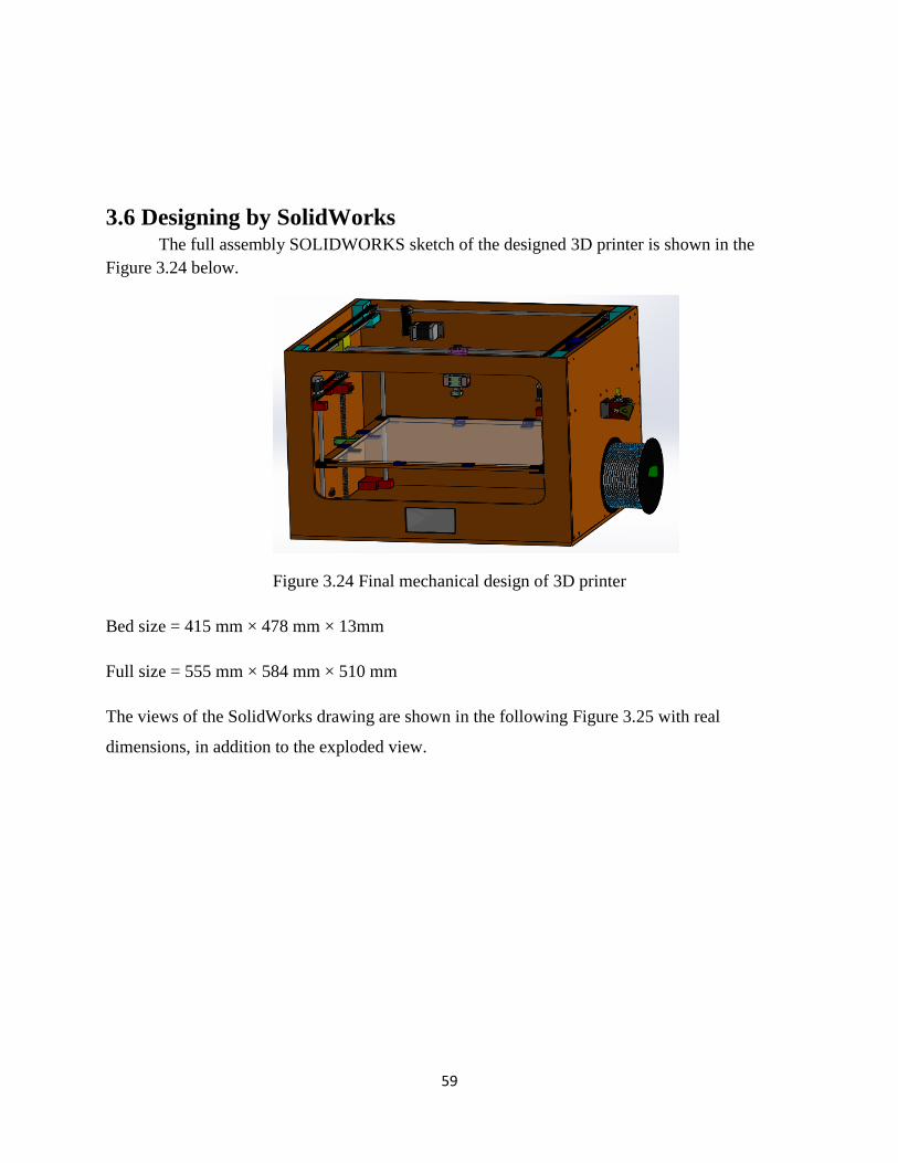
59
3.6 Designing by SolidWorks The full assembly SOLIDWORKS sketch of the designed 3D printer is shown in the
Figure 3.24 below.
Figure 3.24 Final mechanical design of 3D printer
Bed size = 415 mm × 478 mm × 13mm
Full size = 555 mm × 584 mm × 510 mm
The views of the SolidWorks drawing are shown in the following Figure 3.25 with real
dimensions, in addition to the exploded view.

60
Figure 3.25 Views of the SolidWorks drawing
3.7 Interfacing Interfacing is the point of interaction between the software and hardware, a
microcontroller can be interfaced with other devices, such as sensors, motors, switches, keypads,
displays, memory and even other microcontrollers. In our 3D printer, there are some components
that are interfaced digitally like the LCD controller and drivers of the stepper motors. Other
components need analog interfacing like fans, thermistor and the extruder heater.

61
3.8 Programing In order for the Arduino to function with the RAMPS 4.1, a specific kind of firmware will be
used to control each part in the printer which is called Marlin Firmware. It's a group of libraries
that contain programmable command for leading all the electrical components of the printer such
as, motors movements, filament temperature, PID values .…etc. Figure 3-26 and Figure 3-27
below shows a copy of the firmware:
Figure 3-26 Some commands of Marlin firmware

62
Figure 3-27 Another part of Marlin firmware
3.9 Slicing process Computer transforms the 3D sketch (e.g. Solid Works sketch) to a code that the
microcontroller understands which is known as the G-code or G-programming language-code is
a language in which people tell computerized machine tools how to make something. The how is
defined by instructions on where to move, how fast to move, and through what path to move, this
method is used for CNC machines and 3D printers. The following Figure 3.28 concludes the
slicing process.
Figure 3.28 Slicing process
63
3.10 Software 3D printers extrude plastic like ABS or PLA from filament. The filament is pulled into the
extruder and heated in its nozzle (hot end) and finally deposited. The extruder (also called print-
head) will move while extruding, or move (jump) without extruding. A slicer program allows to
calibrate printer settings for various types of "areas to print", like:
Extrusion speed (rotations / minute).
Head speed temperature.
Fan on/off.
The program allows defining:
Wall thickness filling patterns.
Extrusion speed, head speed and temperature per type of area.
Deposited filament for a layer or a section of a layer depends on extrusion speed, head
movement speed, and temperature. In addition, factors like movement patterns, plastic brand, fan
on/off …etc. Also have an influence on the design [25]. Some examples on slicer and control
software:
Skeinforge, SFACT slicer, Slic3r, Repetier-Host, and Netfabb are some examples on slicers. In
our project Repetier-Host will be used which is easy to use and is suitable for our needs.
3.11 Manufacturing In 3D-Printer project many machines will be used as (Milling, Turning, Drilling, CNC,
Shipping, and Cutting) to produce parts to be ready for assembly.
Milling machine use to make the surfaces smooth and the thickness can be reduced of parts
where it has high accuracy and fast work. This machine will be used for substrates and extruder
also in feeder because these parts should be accurate dimension. The reason behind that is the
substrates will give the strength to the bed of 3D-printer and for extruder it's needed to have
specific thickness so the cooling system can cool the filament easily, and for the feeder should be
not have huge space so that will make the filament easily pass during the feeder also it will not
have space to leave the filament without tension.

64
Drilling machine is almost used in all the parts by making holes to join the parts by using screw,
another application of that it's used to join the rod inside the supporter after fit it with bearing.
Turning machine will be used to all parts which have cylindrical shapes as rod to reduce the
diameter of rod in addition to chamfer the edges so it will be easier to insert it in the supporter or
substrates.
CNC machine, will be used for high accuracy and for some material as wood as some parts for
frame of bed in the 3D printer and the holder of the extruder because it needs high accuracy to
produce.
Cutting machine will be used to make the frame of the 3-printer like having places with specific
dimension as LCD location.
3.12 Assembling The assembly process will be accomplished by joining all the parts of the system together.
Mechanical machines will be used to join all the parts together. To begin with, the wooden box
of the 3D-Printer will be cut and shaped into different sizes of rectangular shapes and a window
for the front and drill it in the corners where wooden supporters will be held by screws. After
that, the 3 axes will be put and connected by the supports, screws and pulleys so they can move
easily. The motors will be held by using belts and pulleys to let them move tightly. Then, the
extruder will be drilled to insert the heater and the thermistor in it and fix it by the plastic
supports on the Y axis, the same process will be done for the feeder. Moreover, the plastic
filament will be fixed on the outside wall of the wooden box. For the steel plate, it's going to be
set horizontally by using 8 Z shaped aluminum supporter and springs to adjust the balance of it.
Finally, for the electronic components, the RAMPS board will be set on the Arduino and 5
stepper motors, heater, the thermistor, 2 fans, 4 stepper drivers, LCD screen, 5 end stops and 12V
DC power supply will be connected to the RAMPS .
3.13 Cost Analysis and Suppliers List In this section required materials, components, their quantities, prices and suppliers list will be
introduced.
The following Table 1 shows the previous requirements:

65
Table 1 Cost Analysis and Suppliers List
Item
Quantity
Price per
unit (TL)
total cost
(TL)
Supplier
Stepper motors 5 45 225 Robotizmo, Istanbul,
Turkey
Arduino Mega 2560 1 45 45 Robotizmo, Istanbul,
Turkey
Belt pulley 14 9 126 Robotizmo, Istanbul,
Turkey
Linear Bearings 20 16 320 Robotizmo, Istanbul,
Turkey
Threaded rods 2 30 60 Famagusta industrial
area, Cyprus
608 Bearings 10 7.5 75 Robotizmo, Istanbul,
Turkey
Linear rods 10 6.5 65 Robotizmo, Istanbul,
Turkey
Nuts 2 3 6 Famagusta industrial
area, Cyprus
Belt 14 m 9 126 Robotizmo, Istanbul,
Turkey

66
NTC thermistors 10 6.5 65 Robotizmo, Istanbul,
Turkey
RAMPS 1.4 1 35 35 Robotizmo, Istanbul,
Turkey
Stepper drivers 5 10 50 Robotizmo, Istanbul,
Turkey
End stops 5 6.5 32.5 Robotizmo, Istanbul,
Turkey
Graphical LCD 1 65 65 Robotizmo, Istanbul,
Turkey
Nozzle 1 5 5 Robotizmo, Istanbul,
Turkey
Pneumatic Fittings 2 4 8 Famagusta industrial
area, Cyprus
Fan 2 7.5 15 Robotizmo, Istanbul,
Turkey
Cartridge heater 1 7.5 7.5 Robotizmo, Istanbul,
Turkey
8mm*50cm shafts 10 11 110 Robotizmo, Istanbul,
Turkey
PTFE tubing 2*4 2m 10 20 Robotizmo, Istanbul,
Turkey
PTFE tubing 3*5 4m 23 92 Robotizmo, Istanbul,
Turkey

67
Jumping wires 25 1.5 38 Robotizmo, Istanbul,
Turkey
Bolts 20 1 20 Famagusta industrial
area, Cyprus
Electrical wires 21m 1 21 Electrical shop,
Cyprus
Set screws 5 1 5 Famagusta industrial
area, Cyprus
3D Printer filament 1 KG 65 65 Robotizmo, Istanbul,
Turkey
Plastic supporters 10 20 200 Rhino3d, Istanbul,
Turkey
Feeder 1 50 50 Rhino3d, Istanbul,
Turkey
Wood 16 - 150
University
Carpenter,
Famagusta, Cyprus
Total cost 2102 Tl

68
Table 2 below illustrates other payments that were paid in order to get the previous components.
Table 2 Miscellaneous Costs
Miscellaneous Costs Price (TL)
Transportation 30
Delivery 90
Total cost 120

69
CHAPTER 4
MANUFACTURING AND ASSEMBLY
This chapter will explain how the manufacturing process was conducted; also details of assembly
step by step and testing of final project will be reported.
4.1 Manufacturing To manufacture the prototype, components were manufactured in the workshop using
conventional (Cutting, drilling, welding, grinding, joining) and modern manufacturing
techniques (3D Printer).
4.1.1 Wooden Box
The wooden box protects the mechanical and electrical parts of the printer inside it. The
following steps were taken in order to manufacture it:
1. Measuring the dimensions of the wooden slices as the following: (see Figure 4.1)
(554.99x500x10 mm) 1 piece (see APPENDIX C DRAWING NO 1-31)
(500x584x10 mm) 1 piece (see APPENDIX C DRAWING NO 2-31)
(500x574x10 mm) 2 pieces (see APPENDIX C DRAWING NO 3-31 )
(500x534.99x10 mm) 1 piece (see APPENDIX C DRAWING NO 5-31)

70
Figure 4.1 Box wooden
2. Cutting the wooden pieces by a wood combination machine as in Figure 4.2
Figure 4. 2 Cutting the wooden slices
.

71
4.1.2 Plastic Supporters
The plastic supporters are used to set the moving components or that will carry weight. They
were manufactured in our department's workshop by the CNC machine but the raw material was
not suitable for the machine. Therefore; 3D printing was the best solution for making them
because it can use convenient kind of plastic that could give the wanted parts more accurate
dimensions.
The plastic pieces were manufactured by a 3D printer as in Figure outside the workshop (see
APPENDIX C DRAWING NO 6-31, NO 7-31, NO 11-31, NO 17-31, NO 18-31, NO 19-31, NO
23-31, NO 25-31, NO 24-31, NO 26-31, NO 30-31 ). But there were some problems with them,
like some holes were tight, for widening them by an adjustable fixing machine.
Figure 4. 3 Two types of plastic supporters
4.1.3 Wooden Supporters
The wooden supporters are used to fix several components that don't bear much pressure as long
as they are weaker than plastic. It choose L shape as connect between shafts for Z axis and it has
been made the teeth plastic to connect the belt for X,Y axes .

72
(See APPENDIX C DRAWING NO 14-31, NO 12-31, NO 20-31, NO 22-31, NO 27-31, NO 28-
31, NO 29-31)
They were manufactured by using the milling machine to adjust the height and width of each
block as they were designed before.
Then the drilling machine was used to create the holes on the wood to set the shafts and for the
bearing .
4.1.4 Managing the Belts
For controlling the shafts movements synchronously between two points in the X, Y, Z axis,
specific lengths of the belt should be cut for connecting two points and make them tight enough
to lead the motors to move in precise steps.
There were two methods to make close loops of the belt pieces:
1. By designing small plastic slices (See APPENDIX C DRAWING NO 26-31), which
have teeth to catch the belt better in order to increase the fraction between the belt and
the shaft for the Y and X axes as shown in Figure 4.7
Figure 4. 4 Catching the belt by a plastic slice
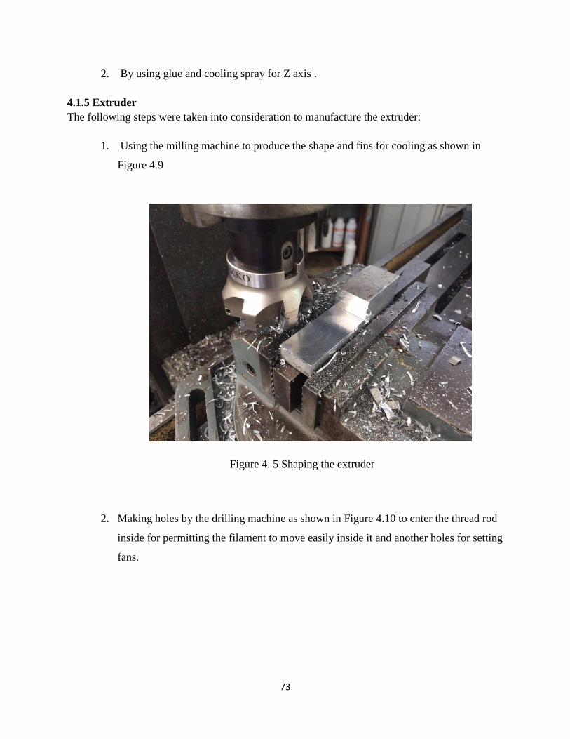
73
2. By using glue and cooling spray for Z axis .
4.1.5 Extruder
The following steps were taken into consideration to manufacture the extruder:
1. Using the milling machine to produce the shape and fins for cooling as shown in
Figure 4.9
Figure 4. 5 Shaping the extruder
2. Making holes by the drilling machine as shown in Figure 4.10 to enter the thread rod
inside for permitting the filament to move easily inside it and another holes for setting
fans.

74
Figure 4. 6 Drilling the extruder
3. Another piece of aluminum was cut with the same diameter of the thread rod and
another two holes were produced for the cartridge heater and the thermistor and one
in the bottom for the nozzle.
Figure 4.7 shows the last design of the extruder (See APPENDIX C DRAWING NO
16-31).
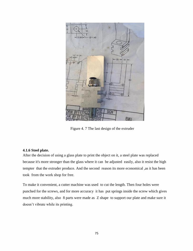
75
Figure 4. 7 The last design of the extruder
4.1.6 Steel plate.
After the decision of using a glass plate to print the object on it, a steel plate was replaced
because it's more stronger than the glass where it can be adjusted easily, also it resist the high
tempter that the extruder produce. And the second reason its more economical ,as it has been
took from the work shop for free.
To make it convenient, a cutter machine was used to cut the length. Then four holes were
punched for the screws, and for more accuracy it has put springs inside the screw which gives
much more stability, also 8 parts were made as Z shape to support our plate and make sure it
doesn’t vibrate while its printing.
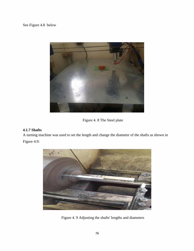
76
See Figure 4.8 below
Figure 4. 8 The Steel plate
4.1.7 Shafts
A turning machine was used to set the length and change the diameter of the shafts as shown in
Figure 4.9:
Figure 4. 9 Adjusting the shafts' lengths and diameters

77
4.2 Assembly The assembly process was accomplished by joining all the parts of the system together as shown
in Figure 4.9
Figure 4. 9 Prototype after assembling
First of all, the five pieces of wood were combined together with screws to build the wooden box
as in Figure 4.10
Figure 4. 10 The last prototype of the wooden box
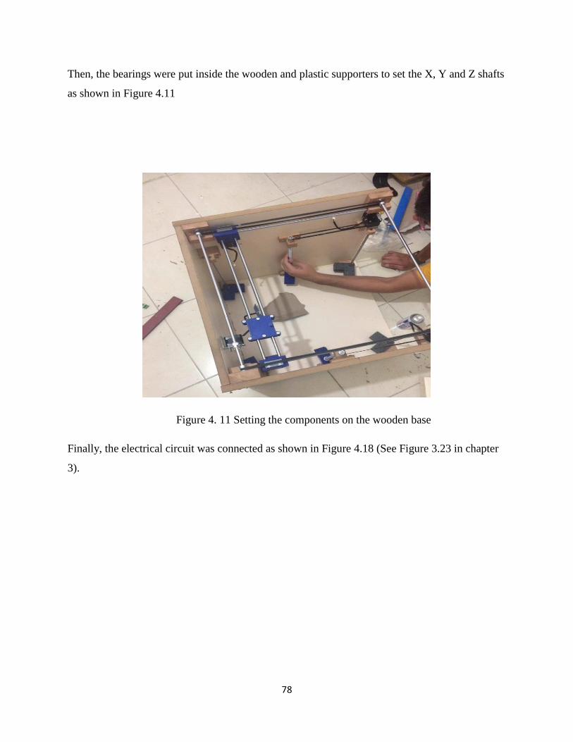
78
Then, the bearings were put inside the wooden and plastic supporters to set the X, Y and Z shafts
as shown in Figure 4.11
Figure 4. 11 Setting the components on the wooden base
Finally, the electrical circuit was connected as shown in Figure 4.18 (See Figure 3.23 in chapter
3).

79
CHAPTER 5
RESULTS AND DISCUSSIONS
5.1 Testing of Final Project
After manufacturing process is done, and all components were assembled together, the Marlin
firmware was uploaded to the Arduino, and a simple shape was designed and also uploaded to
the Repetier software to be printed as shown in Figure 5.1
Figure 5. 1 Repetier software

80
Then, the plastic filament was filled inside the PTFE tube to lead it to the extruder. After that, the
cartridge heater was programmed in order to increase its temperature to 210 C as shown in
Figure 5.2
Figure 5. 2 Setting the heater's temperature
Finally, the printer started to move and print the object layer by layer as shown in Figure 5.3
Figure 5. 3 Printing an object

81
After the printing process was finished, the last prototype of the final printed object is seen in
Figure 5.4
Figure 5. 4 The last prototype of the final printed object
5.2 Discussion of Results After testing the project, all the results were satisfied into a certain point. But the efficiency of
the printed objects could be enhanced by increasing the accuracy of the manufacturing process of
the components, several factors were found that caused these unwanted results. Firstly, the
extruder was not made in good quality and modern machines; that led to be cleaned every time
it's used which is not supposed to be like that. Secondly, the extruder was shaking due to the belt
weakness and the performance of the stepper motors. In addition, the power supply wasn't
supplying enough power for moving the motors with suitable speeds and for heating the heater
properly. Nevertheless, the plastic was solidifying inside the nozzle. Finally, the steel plate
wasn't light enough for the Z axis to move with the right steps and also because of the friction.
5.3 Technical Difficulties Many difficulties were faced during the process of manufacturing, assembling and testing. The
accuracy of the workshop machines was not good enough to produce the parts in high quality
because they were old and the drilling machine has been deflected. Moreover, it was almost hard
for the Z axis to move easily because of the high friction and the weight of the plate, so a
lubricant material was put to decrease the fraction. In addition, the LCD screen was not

82
compatible with the RAMPS board which led to changing some programming commands to
work properly. Finally, the plastic was stick inside the nozzle, so it was fixed by putting a small
piece of PTFE tube inside it and changed the place of the feeder motor above the extruder to ease
the filament dragging inside it.

83
CHAPTER 6
FUTURE WORK & CONCLUSION
The future works and developments of the project will be discussed in this chapter as well a final
conclusion.
6.1 Future Work The project is a simple type of a 3D printer with basic features, therefore some developed
suggestions are wished to be added in the future. Firstly, the printer will not just print an object
from programmed commands, but it’ll also capture and scan any real shape and directly print it.
Secondly, the efficiency of the printer will be worked on, so it’ll print more rapidly an
accurately. Thirdly, the extruder would be rebuilt to accept more than 210 temperature in
order to use other plastic filaments with good quality. Finally, a smaller prototype of the printer
would be better to deal with. As long as all other similar projects have all the previous features,
it’s not difficult for them to be added someday.
6.2 Conclusion This report has explained the construction of an ordinary 3D printer by its all aspects. The report
summarized the engineering problem and the objective of the project. Then, a brief history and a
comparison between different types of 3D printers were introduced. Later, project mechanical
and electronic components were proposed, materials were selected, design related calculations
were solved by using suitable formulas, programming process with convenient software and cost
analysis with detailed list of suppliers were illustrated. Moreover, manufacturing steps were
explained in details, assembling process has been clarified, testing was conducted and
experimental results were reported. Finally, these experimental results were plugged into related
equations and calculations were made. As a conclusion, 3D printer is an excellent alternative for
creating products as if it compare with CNC machine ,The CNC would take more time and it
couldn’t do the shape as 3D because it's cutting not building as 3D from filament instead of
regular machines that are used nowadays. Although its efficiency and accuracy is low, it can
become more sophisticated and improved by extending it with advanced settings and
manufacturing technologies in the upcoming years.

84
REFERENCES
[1] 3D Wax Pattern Production System. (2011, February 21). Retrieved from 3D systems:
http://www.3dsystems.com/products/datafiles/projet/ProJet_CPX_3000.Pdf.
[2] GOLDBERG, D. (2014, september 5). History of 3D Printing: It’s Older Than You Are (That
Is, If You’re Under 30). Retrieved from lineshapespace:
http://lineshapespace.com/history-of-3d-printing/.
[3] Majcher, K. (2014, September 16). How to Build 3-D Printing. Retrieved from MIT
Technology Review: http://www.technologyreview.com/news/530721/how-to-build-3-d-
printing/.
[4] 3D Printing Processes:The Free Beginner’s Guide. (n.d.). Retrieved from 3D PRINTING
INDUSTRY: http://3dprintingindustry.com/3d-printing-basics-free-beginners-
guide/processes/.
[5] BV, J. V. (2014). Stereolithography (SLA-SMS) for 3D printing. Retrieved from
RapidPrototyping.NL: http://en.rapidprototyping.nl/3d-printing/techniques-in-3d-
printing/stereolithography-sla-sms-for-3d-printing/.
[6] Laminated Object Manufacturing. (2006, April 10). Retrieved April 19, 2008, from
WIKIPEDIA: https://en.wikipedia.org/wiki/Laminated_object_manufacturing.
[7] National Instruments. "Robotics Fundamentals Series" Retrieved, 2008.
[8] New Japan Radio Co. Ltd." Stepper Motor Basics". Retrieved 2012.
[9] Ericsson. "Stepper Motor". Retrieved 2011.
[10] A4988 Stepper Motor Driver. (2014, November). Retrieved from Pololu:
http://www.pololu.com/product/1182.
[11] Single Bipolar Stepper Motor Driver A4988. (2005, December). Retrieved from Pololu :
http://www.robotshop.com/media/files/PDF/datasheet-1182.pdf.
[12] Omgitsbud. (n.d.). A4988 DMOS Microstepping Driver. Retrieved from
https://upverter.com/upn/b404724b2594c5ca/.
[13] Allegro Micro Systems, Inc. "DMOS Micro stepping Driver". Retrieved 2014.
85
[14] A4988 Stepper Motor Driver. (2012, December). Retrieved from Robotronics:
http://www.robotronics.com.au/web/products/a4988-stepper-motor-driver.
[15] Bipolar Stepper Motor Drivers. (n.d.). Retrieved from Allegro MicroSystems.LLC:
http://www.allegromicro.com/en/Products/Motor-Driver-And-Interface-ICs/Bipolar-
Stepper-Motor-Drivers.aspx.
[16] Cartridge Heating Elements. (2014). Retrieved from Cynebar:
http://www.cynebar.com.au/cartridge-heater.php.
[17] (2014, December 27). Retrieved from http://reprap.org/wiki/End_stop.
[18] GLCD Supplement. (n.d.). Retrieved from Maker's Tool Works:
http://www.manula.com/manuals/maker-s-tool-works/mendelmax-3-assembly-
guide/1/en/topic/glcd-supplement.
[19] Roger Timings . Mechanical Engineer's Pocket Book . (14 Dec 2005)
[20] Earl, B. (2015, September 29). All About Stepper Motors. Retrieved from sdafruit learning
system: https://learn.adafruit.com/downloads/pdf/all-about-stepper-motors.pdf.
[21] Application Of Cartridge Heaters. (n.d.). Retrieved from OMEGA:
http://www.omega.com/prodinfo/CartridgeHeaters.html.
[22] Freson. (2008, March 18). How To Find The Belt Length. Retrieved from
https://frentzandsons.com/Hardware%20References/tofindthebeltlength.htm.
[23] PID Controller Simplified. (2008, May 11). Retrieved from
https://radhesh.wordpress.com/2008/05/11/pid-controller-simplified/.
[24] Design Techniques. (n.d.). Retrieved from
http://www.facstaff.bucknell.edu/mastascu/econtrolhtml/PID/PID3.html.
[25] R., K. (2015, October 15). Slicers and user interfaces for 3D printers. Retrieved from
EDUTECH WIKI:
http://edutechwiki.unige.ch/en/Slicers_and_user_interfaces_for_3D_printers.
[26] (n.d.). Retrieved from IEEE STANDARDS ASSOCIATION: http://standards.ieee.org/.
[27] (n.d.). Retrieved from IEC International Standards: https://webstore.iec.ch/.

86
APPENDICES

87
APPENDIX A - LOGBOOK Logbook: Massa Alsafadi 149110
DATES DETAILS
14/10/2015
Firstly, I joined my project team that consists of 3 students including me.
I discussed the project topic with my advisor who is different from theirs
Dr. Prof. Mustafa Kemal Uyguroglu and explained briefly about the
electrical part of the project.
20/10/2015 I started searching for topics related to the 3D printer needs and gathering
information from different sources.
22/10/2015 First meeting with the team members was held to discuss the 3D printer
function and components.
25/10/2015 Report format and needed topics were known.
27/10/2015 A group meeting was held to distribute our duties.
29/10/2015 I met my advisor and asked him about the electrical function of the 3D
printer.
9/11/2015 Exact electrical components were chosen.
16/11/2015 My members and I started define the calculations.
20/11/2015 I began to write the "Introduction" and "Why 3D printer?" parts in the
first chapter.
30/11/2015 I started to write my duties in the second chapter.
7/12/2015 A group meeting was held to manage the third chapter topics.
10/12/2015 I started writing stepper motor, stepper driver, extruder and end Stops
sections and their calculations in the third chapter.
17/12/2015 I visited my advisor and he gave me some tips and notes about my

88
writing.
20/12/2015 I drew the electrical circuit of the 3D printer and searched for engineering
standards.
23/12/2015 A meeting was held for repairing and organizing the report.
25/12/2015 I revised my advisor for checking my parts.
26/12/2015 I added my logbook and the references.
28/12/2015 I submitted the report to my advisor.
1/2/2016 A group meeting was held to select our materials and components.
26/2/2016 My group mates and I had meeting to share our search results.
3/3/2016 We decided which suppliers to visit and started in Famagusta industrial
areas.
9/3/2016 My group and I found a supplier in Istanbul and ordered the components.
22/3/2016 We found a Turkish supplier to print some components.
31/3/2016 We started to combine and try the electrical circuit.
3/3/2016 A group meeting was held to discuss some problems.
1/4/2016 I had a meeting with my adviser to share information.
21/4/2016 I started to edit the old report.
24/4/2016 I searched on the web for the programming part.
2/5/2016 We tested the electrical components and made sure that they're fine.
6/5/2016 My group and I assembled the electrical and mechanical parts
12/5/2016 We worked on wiring the electrical circuit.

89
20/5/2016 I searched for some solutions for the extruder's problems.
25/5/2016 I brought fans for cooling the heated circuit
29/5/2016 I completed writing the report.
30/5/2016 We showed our final work to our advisor.

90
Logbook: Louai Mikawi 127340
DATES DETAILS
14/10/2015 Firstly, I joined my project team that consists of 3 students including
me. I discussed the project topic with my advisor Dr. Davut Solyalı
20/10/2015 I started searching for topics related to the 3D printer needs and
gathering information from different sources.
22/10/2015 First meeting with the team members was held to discuss the 3D
printer function and components.
25/10/2015 Report format and needed topics were known.
27/10/2015 A group meeting was held to distribute our duties.
29/10/2015 I talked with my supervisor about the idea that we have
9/11/2015 Exact mechanical components were chosen.
16/11/2015 My members and I started define the calculations.
20/11/2015 I began to write the "Types of 3D machine" and "History of 3D-
Printer" parts in the first chapter.
30/11/2015 I started to write my duties in the second chapter.
7/12/2015 A group meeting was held to manage the third chapter topics.
10/12/2015 I started writing mechanical component that we need in details.
17/12/2015 We choose the material that we need and write about it .
19/12/2015 After the design I wrote the assembly.
20/12/2015 I wrote about the calculation for mechanical component, before test
it
23/12/2015 A meeting was held for repairing and organizing the report.
25/12/2015 I finished the interface and software.
26/12/2015 I added my logbook and the references.
1/2/2016 A group meeting was held to select our materials and components.
26/2/2016 My group mates and I had meeting to share our search results.
1/3/2016 we started to manufacture the wooden box.
3/3/2016 We decided which suppliers to visit and started in Famagusta
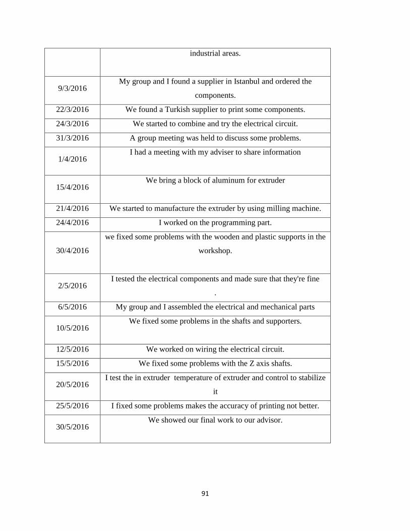
91
industrial areas.
9/3/2016 My group and I found a supplier in Istanbul and ordered the
components.
22/3/2016 We found a Turkish supplier to print some components.
24/3/2016 We started to combine and try the electrical circuit.
31/3/2016 A group meeting was held to discuss some problems.
1/4/2016 I had a meeting with my adviser to share information
15/4/2016 We bring a block of aluminum for extruder
21/4/2016 We started to manufacture the extruder by using milling machine.
24/4/2016 I worked on the programming part.
30/4/2016
we fixed some problems with the wooden and plastic supports in the
workshop.
2/5/2016 I tested the electrical components and made sure that they're fine
.
6/5/2016 My group and I assembled the electrical and mechanical parts
10/5/2016 We fixed some problems in the shafts and supporters.
12/5/2016 We worked on wiring the electrical circuit.
15/5/2016 We fixed some problems with the Z axis shafts.
20/5/2016 I test the in extruder temperature of extruder and control to stabilize
it
25/5/2016 I fixed some problems makes the accuracy of printing not better.
30/5/2016 We showed our final work to our advisor.

92
Logbook: Mustafa Altabshi 137944
DATES DETAILS
14/10/2015
Firstly, I chose our capstone project with my team members.
Afterword, we had a meeting with our adviser where we have
discussed our project, and learned about that technology.
19/10/2015 Project Proposal Request to Dr. Davut Solyali and Assist. Prof. Dr.
Neriman Özada (Vice Chair).
22/10/2015 Group meeting was held. I started working on Gantt chart.
25/10/2015 Conversing about the objective and scope of our project, learning
more information’s on 3D printer technology.
27/10/2015 Group meeting was held and duties were distributed where I took the
responsibility to design our 3D printer.
29/10/2015 My team members and I suggested several designs and ideas with
our advisor.
31/10/2015 I started looking for 3D printer various types.
2/11/2015 I have talked with some friends, who are expert in 3D printer, which
would give us a good start and avoid mistakes.
6/11/2015 I started drawings design 3D printer using SolidWorks software.
9/11/2015 We met our advisor and asked for his help in choosing the electrical
and mechanical components.
16/11/2015 I and my team members started with calculations.
20/11/2015 I started writing my part of introduction chapter.
30/11/2015 I started writing the types of 3D printer for literature review chapter.
7/12/2015 My team members and I visited our advisor for extra information
and explanation. Preliminary design was suggested.
10/12/2015 I started selecting the materials for our project.
17/12/2015 I sent my final works to my other team members and we worked on
organization of the report.

93
20/12/2015 I drew 3D circuit of electrical components of the 3D printer.
23/12/2015 We made a review for whole report to insure that everything is
perfect.
26/12/2015 I prepared my logbook.
28/12/2015 We have submitted the final report to the supervisor Assit.Prof.
Neriman Ozada.
1/2/2016 A group meeting was held to select our materials and components
26/2/2016 My group mates and I had meeting to share our search results
1/3/2016 we started to manufacture the wooden box.
3/3/2016 We decided which suppliers to visit and started in Famagusta
industrial areas.
9/3/2016 My group and I found a supplier in Istanbul and ordered the
components.
22/3/2016 We found a Turkish supplier to print some components.
24/3/2016 I started to bring all component that we need after study the future
work
31/3/2016 A group meeting was held to discuss some problems.
1/4/2016 I had a meeting with my adviser to share information
15/4/2016 We bring a block of aluminum for extruder
21/4/2016 We started to manufacture the extruder by using milling machine.
25/4/2016 I worked on thread rod by using turning machine .
30/4/2016
we fixed some problems with the wooden and plastic supports in the
workshop.

94
2/5/2016 I make some research and calculation for belt and torque
6/5/2016 My group and I assembled the electrical and mechanical parts
10/5/2016 We fixed some problems in the shafts and supporters.
12/5/2016 We worked on wiring the electrical circuit.
30/5/2016 We showed our final work to our advisor.

95
APPENDIX B - GANTT CHART
20
Oct
20
Nov
15
Dec
28
Dec
1
Feb
27
Feb
15
Mar
13
Apr
10
May
28
May
Preparing Gantt chart
Objectives and problem
statements
Researches about the
project
Managing the duties
Choosing the components
Design calculations
Drawing & designing
Writing the introduction
chapter
Writing the literature
review chapter
Writing the design and
manufacturing chapter
Searching for the
components & materials
Electrical & mechanical
parts order
Manufacturing wooden &
plastic supporters
Building the wooden box
Manufacturing the
extruder
Connecting & Testing the
electrical circuit
Working on the
programming part
Assembly of prototype
components
Testing
Completing the report
Figure B1. Gantt Chart

96
APPENDIX C - DRAWINGS

97

98

99

100

101

102
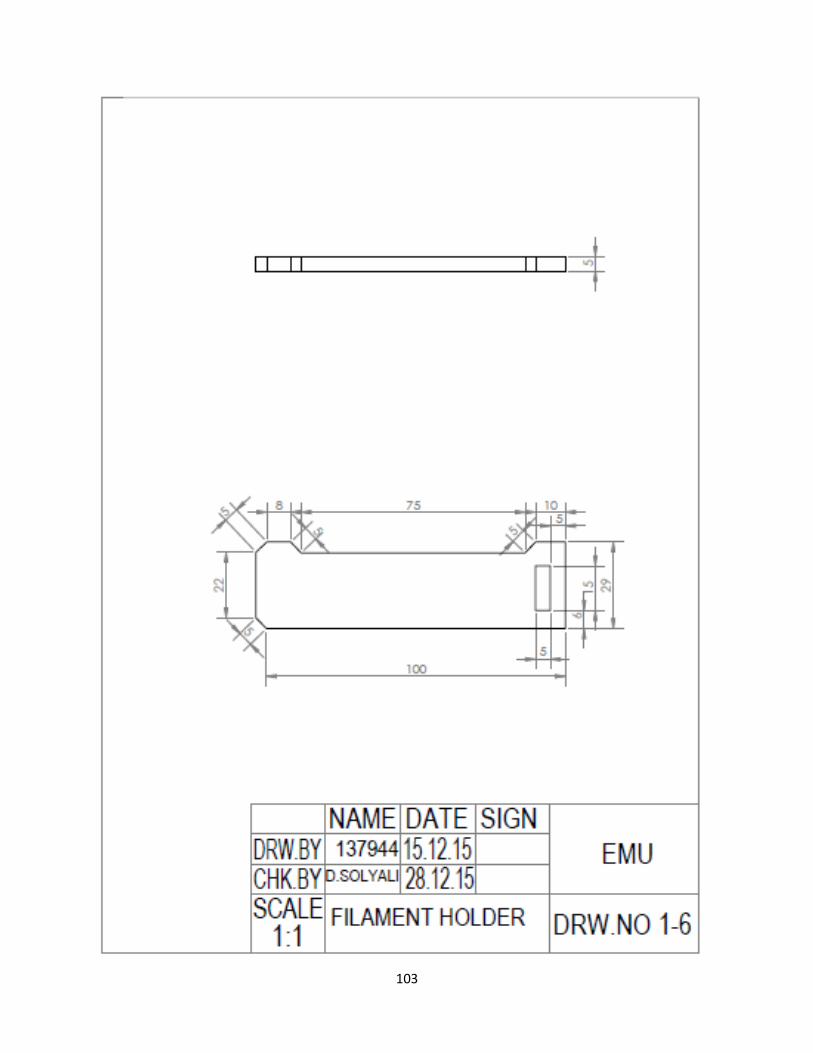
103

104
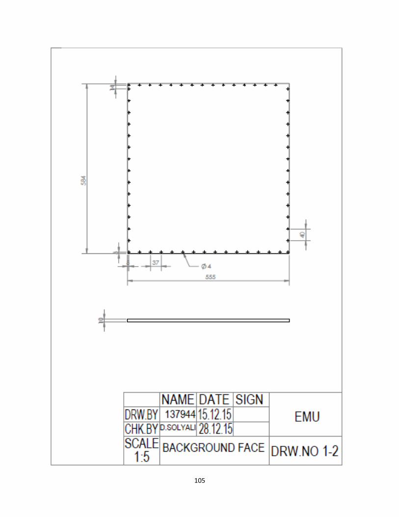
105

106

107

108

109

110

111

112

113
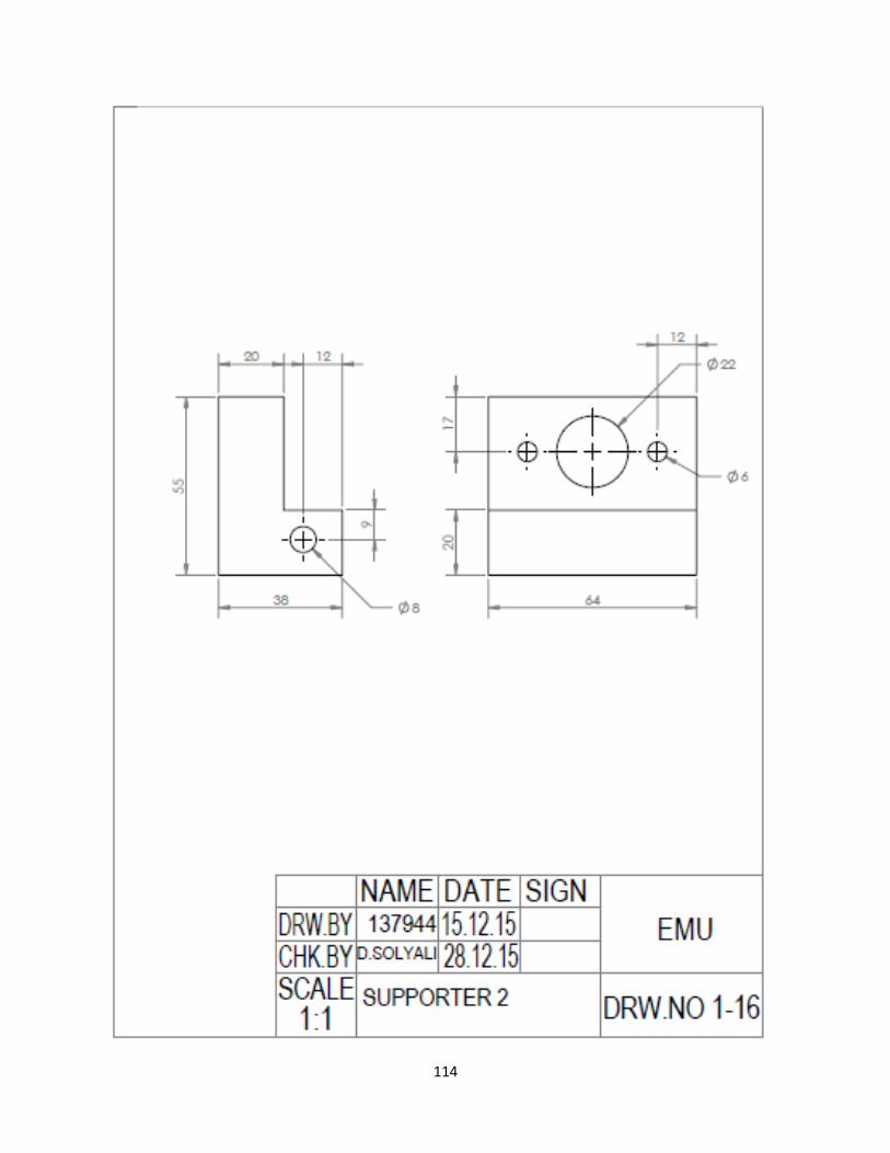
114

115

116

117

118

119

120

121

122

123

124
APPENDIX D - ENGINEERING STANDARDS
Electrical Engineering Standards
Several electrical engineering standards that are used in this project will be introduced in this
section:
Standards from IEEE (The Institute of Electrical and Electronics Engineers):
IEEE 1255-2000 – IEEE guide for evaluation of torque pulsations during starting of
synchronous motors.
IEEE P3030 - intended as the first draft standard to define an architectural framework for
consumer 3D printing based upon interoperability and portability of 3D printing
solutions, but it's still under test nowadays.
IEEE 1142-1995 guide for the design, testing, and application of moisture-impervious,
solid dielectric, 5–35 kV power cable using metal-plastic laminates [26].
Standards from IEC (The International Electrotechnical Commission):
IEC 60539-2:2003 is applicable to surface mount directly heated negative temperature
coefficient thermistors, typically made from transition metal oxide materials with
semiconducting properties. https://webstore.iec.ch/publication/2481
IEC 60063:2015 provides series of preferred values for the resistance of resistors and for
the capacitance of capacitors.
IEC 60073 Basic Safety principles for man-machine interface, marking and identification
- coding principles for indicators and actuators [27].

125
Mechanical Engineering Standards
Table D.1: Bolt specifications

126
Table D.2: Nuts specifications according to ASMEANSI B18.2.4.6M-2010

127
Table D.3: Nuts specifications according to DIN 439-1-1987

128
Table D.4: Threaded rod specifications according to DIN 975-1986

129
Table D.5: Set screw specifications according to ISO 7434-1983
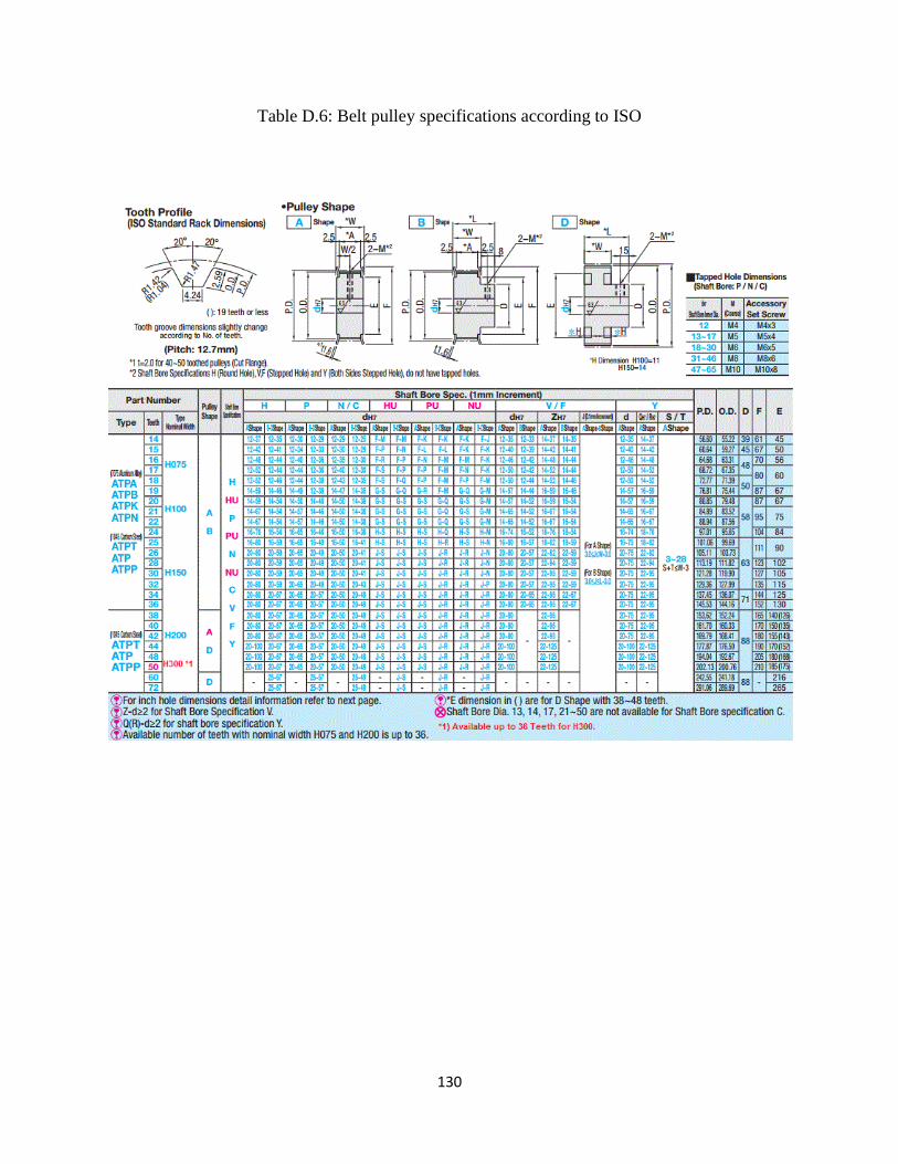
130
Table D.6: Belt pulley specifications according to ISO

131
Table D.7: Braided cable sleeving specifications

132
Table D.8: Belt specifications according to DIN/ ISO 10823

133
Table D.9: Hard coated linear rod specifications

134
Table D.10: Thermistor specifications
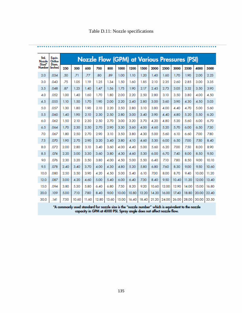
135
Table D.11: Nozzle specifications

136
APPENDIX E - MANUFACTURING PHOTOS
Figure E. 1 Cutting the wooden slices
Figure E- 2 The final design of the wooden box

137
Figure E- 3 Shaping the extruder

138
Figure E- 4 Drilling the extruder
Figure E- 5 The final design of the extruder

139
Figure E- 6 Adjusting the shafts' lengths and diameters
Figure E- 7 Testing the electrical circuit

140
Figure E- 8 Printing an object
Figure E- 9 Prototype after assembly

141
APPENDIX F – POSTER & WEBSITE

142
Figure F- 2 3D Printer Poster