Embed Size (px)
Citation preview
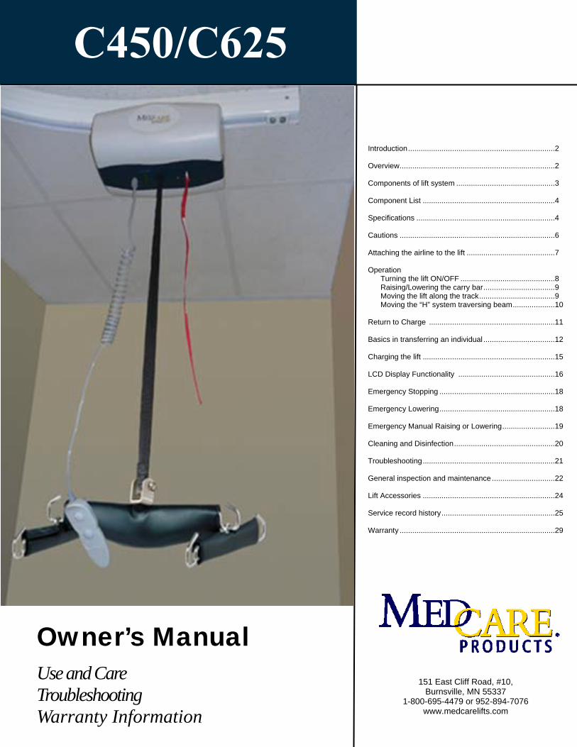
C450/C625
151 East Cliff Road, #10, Burnsville, MN 55337
1-800-695-4479 or 952-894-7076 www.medcarelifts.com
Introduction ...................................................................... 2 Overview .......................................................................... 2 Components of lift system ............................................... 3 Component List ............................................................... 4 Specifications .................................................................. 4 Cautions .......................................................................... 6 Attaching the airline to the lift .......................................... 7 Operation Turning the lift ON/OFF ............................................. 8 Raising/Lowering the carry bar .................................. 9 Moving the lift along the track .................................... 9 Moving the “H” system traversing beam .................... 10 Return to Charge ............................................................ 11 Basics in transferring an individual .................................. 12 Charging the lift ............................................................... 15 LCD Display Functionality .............................................. 16 Emergency Stopping ....................................................... 18 Emergency Lowering ....................................................... 18 Emergency Manual Raising or Lowering ......................... 19 Cleaning and Disinfection ................................................ 20 Troubleshooting ............................................................... 21 General inspection and maintenance .............................. 22 Lift Accessories ............................................................... 24 Service record history ...................................................... 25 Warranty .......................................................................... 29
Owner’s Manual
Use and Care Troubleshooting Warranty Information
Medcare 450/625 lbs - User Guide (400009) Rev: 14 MAR 2017 Page: 2
CAUTION: DO NOT ATTEMPT TO USE THIS EQUIPMENT WITHOUT FIRST UNDERSTANDING THE CONTENTS OF THIS MANUAL.
Introduction
Overview of MedCare 450/625 lbs lift system
Before using this equipment, and to ensure the safe operation of your Medcare 450/625 lbs lift, carefully read this entire manual, especially the section on “Cautions”. The Medcare 450/625 lbs lift is designed to be used in conjunction with MedCare lift track, accessories and slings. Please refer to any user guides sup-plied with these components and refer to them while reviewing this manual.
Should any questions arise from reviewing this manual contact your local authorized MedCare dealer. Failure to comply with warnings in this manual may result in injury to either the operator, or the individual being lift-ed/transferred. Damage to the lift and/or related components may also occur. Be sure that the contents of this manual are completely understood prior to using this piece of equipment.
Store this manual with the documents included with the lift system and sling (s). Contents of this manual are subject to change without prior written notice.
The MedCare 450/625 lbs lift is an aid used by health care professionals and those providing care in the home to lift, position and transfer clients or a disabled family member. The Medcare 450/625 lbs lift is part of what is termed ceiling lift technology which takes advantage of lifting from above and not from below or the side. Additionally the ceiling lift does not take up valuable floor space as most traditional methods do. Fi-nally, the ceiling lift makes it possible to move mobility impaired individuals with minimal strain or risk to the caregiver, while providing complete safety, dignity and comfort for the client or family member.
The Medcare 450/625 lbs lift is one of three major components that make up this technology. The other two components are the track and sling. The Medcare 450/625 lbs lift runs on the lift track which is securely mounted to the ceiling structure of the institution, or home with the use of ceiling brackets. The track itself is made of specially designed aluminum and comes in many different shapes, lengths and configurations, and is custom tailored and installed to meet your specific requirements. The third component, the sling, is a specially designed fabric accessory that attaches to the lift by means of a carry bar and straps, and holds an individual while the lift, positioning or transfer takes place. Both the track and sling are generally supplied with the lift at the initial time of purchase. Please refer to any user guides supplied with the Medcare 450/625 lbs lift and reference them while reviewing this manual.
The Medcare 450/625 lbs lift is a fixed ceiling lift, that is, it always remains on the lift track. It has the abil-ity to lift an individual up from one location such as bed, move the individual along the track to another loca-tion and finally lower the individual into a chair or bath. It is moved along the track in one of two ways. The first is by manually moving the lift along the track with the aid of a caregiver. The second is by having the lift power itself along the track. The functions of lifting up or down, or moving to the left or right, are accom-plished by pressing buttons of a pneumatically (air) operated hand control. The hand control is attached to the lift by way of a rubber airline tubing. Due to the design of the lift system, it takes very little effort to press a button to perform the desired motion.
Please refer to figures 1A and 1B to see sample floor plans of an installed lift system. Refer to figures 2A and 2B to familiarize yourself with the components of the Medcare 450/625 lbs lift. Figures 3A and 3B show the underside view of the lift as it would be seen by an operator.

Medcare 450/625 lbs - User Guide (400009) Rev: 14 MAR 2017 Page: 3
Components of lift system
Figure 1A - Sample floor plan showing basic components of a ceiling lift system.
BATHROOM
BEDROOM
TRACKBED
BATHCHARGER
LIFT
BEDROOM
BEDBATHROOM
BATHCHARGER
TRACK
LIFT
Figure 1B - Alternate sample floor plan showing basic components of a ceiling lift system.
Figure 2A - Basic components of the ceiling lift
Figure 3A—Underside view of the lift
Figure 2B - The Medcare 450/625 lbs ceiling lift with standard Emergency Stop/
Figure 3B - Photo of underside
Emergency Stop/ Lowering
Carry bar
Lifting tape (strap)
Track
Hand Control
AIRLINE TUBE LIFTING TAPE
Medcare 450/625 lbs - User Guide (400009) Rev: 14 MAR 2017 Page: 4
Specifications of Medcare 450/625 Lift Motor: 24 VDC Traverse Motor: 24 VDC (Optional at time of Purchase) “H” Frame Traverse Motor: 24 VDC (Optional at time of Purchase) Charger Alternate 1 Model: Soneil, 2403SRM30 Charger Alternate 1 Input: 100-240 VAC, 1.5 Amps, 50-60 Hz Charger Alternate 1 Output: 24 VDC, 1.5 Amps Charger Alternate 2 Model: Soneil, 2403SRM20 Charger Alternate 2 Input: 100 VAC 0.45 Amps, 240 VAC 0.22 Amps, 50-60 Hz Charger Alternate 2 Output: 28.8 VDC, 1 Amp Charger Alternate 3 Model: Mascot, 9940 Charger Alternate 3 Input: 100-240 VAC, 0.9 Amps, 50-60 Hz Charger Alternate 3 Output: 29.5 VDC, 1.3 Amps Batteries: 24 VDC (2 x 12 VDC) 5.0 AH, Sealed Lead Acid Lift Case: Flame Retardant ABS Hand Control: Pneumatic Lifting Range: Up to 96” (2438mm) Lift Weight: 21—23.5 lbs.(9.5-10.65Kg) Maximum Load: Standard maximum load 450lbs (204 Kgs). Also available in 625 lbs(283 Kgs). Duty Cycle: 1 Min “ON”-9 Mins “OFF” Rated Performance: 30-40 lifts at 625 lbs.(283 Kgs) , 50-60 lifts at 450 lbs.(204 Kgs) , 1 Min “ON”-9 Mins
“OFF” duty cycle, each lift being 24 inches/610mm at the middle of the lifting range (from 54”/1370mm strap out to 30”/762mm strap out) per full battery. Please note: the lift has a break in period; breaking in of the lift will need to be done before these numbers will be achieved. The breaking in period will vary from lift to lift and is dependent on the frequency of use and the types of load being applied, the higher the load and a greater frequency of use will break in the lift faster.
Max Sound Level: Raising Max load 56.1 dB , Lowering Max load 60.3 dB . Service Life: 22500 Cycles or 10 years , whichever comes earlier. As a precautionary measure, the lifting strap should be replaced every 5000 cycles or 3 years, whichever comes earlier. Higher usage lifts may necessitate more frequent replacement of the lifting strap; please refer to page 22-23 for General Inspection and Maintenance information.
The following components are included with your new Medcare 450/625 lbs lift system:
• Medcare 450/625 lbs lift (Manual or Motorized traverse) • Pneumatic Hand Control • Lift Charger (mounted on the wall or ceiling at the end of the track) • Owner’s Manual • Warranty Card
SLINGS: If a sling has been supplied with the lift refer to the instructions included with the sling.
ACCESSORIES: If additional accessories such as a turntable, or gate system have been supplied with the lift refer to the instructions included with those items.
IMPORTANT: Before initial use, the lift unit must be charged for 4 hours. Refer to section titled "Charging Instructions". The hand control airline tube must also be connected to the lift. If it is not connected refer to the section titled “Connecting airline to the lift”.
Component List
Maximum load of the installed lift is determined by referring to the product label located on side of lift.
Shipping/Storage Conditions: Temperature: -40 to +70 ºC Relative Humidity: 10 to 100% RH Atmospheric Pressure: 500 to 1060 hPa
Medcare 450/625 lbs - User Guide (400009) Rev: 14 MAR 2017 Page: 5
NOTES: Please use the following type of plug for C-450 or C-625 lifts installed in the
UK:
Please use the following type of plug for C-450 or C-625 lifts installed in Australia.
The C-450 or c-625 lift shall be connected to a center-tapped single phase supply circuit when users in the United States connect the equipment to a 240 V supply system.
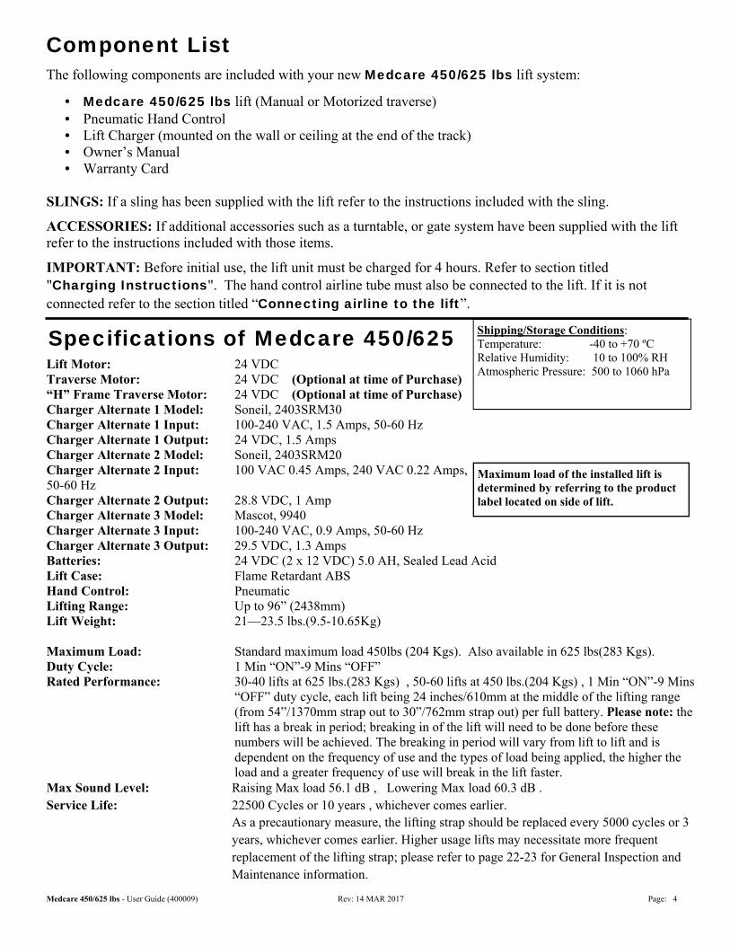
Models Table for Medcare 450/625 lbs Lift
Code Description
323118M C625 Manual Traverse– Quick Curve (Medcare)
323120 C625 Manual Traverse (Medcare)
323126M C625 Power Traverse, RTC (Medcare)
323217M C625 Manual Traverse Rev A (Medcare)
323236M C625 Manual Traverse, Curtain Jumping, Power Turntable (Medcare)
323237M C625 Manual Traverse, Curtain Jumping (Medcare)
323246M C625 Manual Traverse, Power Turntable (Medcare)
323417M C625 Manual Traverse, Omni (Medcare)
323102 C450 Manual Traverse (Medcare)
Lifting Range
21 1/2” (317.5mm)
5 3/4” (146 mm)
12 3/4” (324 mm)
IMPORTANT: Refer to section “IEC-60601-2-7:2007 EMC/EMI compliance Guidelines” for details regarding electromagnetic compatibility information .
Medcare 450/625 lbs - User Guide (400009) Rev: 14 MAR 2017 Page: 6
● The Medcare 450/625 lbs must be installed prior to use. Contact your local authorized dealer to ensure that it is properly installed. The Medcare 450/625 lbs must be installed only by persons authorized by Medcare Products.
● Under no circumstance should the Medcare 450/625 lbs track, lift and sling (s) or entire system be put in control of a person who has not been properly trained in the use and care of this equipment. Failure to adhere to this warning may result in serious injury to the operator, and/or the individual being lifted/transferred.
● The Medcare 450/625 lbs lift, and associated track and sling (s) are not toys. Do not use it for unsafe practices. Do not allow children to play with the lift or any of its’ components.
● The manufacturer's warranty is void if persons unauthorized by Medcare perform work on the C450/C625 lift system.
● There are no user serviceable parts inside the cover. Do not remove cover screws, or open the lift unit, as this will VOID THE WARRANTY.
● In facilities where more than one operator will be responsible for using the Medcare 450/625 lbs lift and associated track and sling (s) it is imperative that all such members be trained in its’ proper use. A training program should be established by the facility to acquaint new operators with this equipment.
● Never expose the Medcare 450/625 lbs lift directly to water. Warranty does not cover any misuse or abuse of the lift system.
● To maintain optimum function, the Medcare 450/625 lbs should be inspected and maintained on a regular basis. See the section titled “General Inspection and Maintenance”.
● Any accessories used with the Medcare 450/625 lbs including track and sling (s), should be checked to ensure that they are in good working order. Check for signs of wear or fraying prior to use. Report any unusual wear, or damage immediately to your local authorized Medcare dealer.
● The Medcare 450/625 lbs lift and associated lift, track and sling (s) are intended only for lifting and transferring of a person. Medcare will not be responsible for any damage caused by the misuse,
neglect or purposeful destruction of the lift, and/or its’ associated components.
● Do not in any circumstance exceed the maximum allowable load of this lift. Refer to the “Specifications” section of this manual, and/or the labels on the side of the lift.
● The installation of the lift, track, accessories, and sling are certified to a maximum load. Do not exceed the maximum rated load of any of the components,
● There is a risk of explosion if the lift is used in the presense of flammable anaesthetics.
● Ensure that a clear space is maintained around the lift and track. Move all curtain material and other obstacles out of the way before performing a transfer. The charger must be located outside the patient vicinity at all times. The patient vicinity is the space
with surfaces likely contacted by the patient or an attendant who can touch the patient. This space is 6 feet (1.83m) beyond the perimeter of the bed, examination table, etc., extending vertically 7-1/2 feet (2.29m) above the floor.
Medcare 450/625 lifts can be decommissioned/disposed of after recommended service life in ac-cordance with regional component specific disposal recommendations.
Cautions
Medcare 450/625 lbs - User Guide (400009) Rev: 14 MAR 2017 Page: 7
Attaching the airline tube to the lift
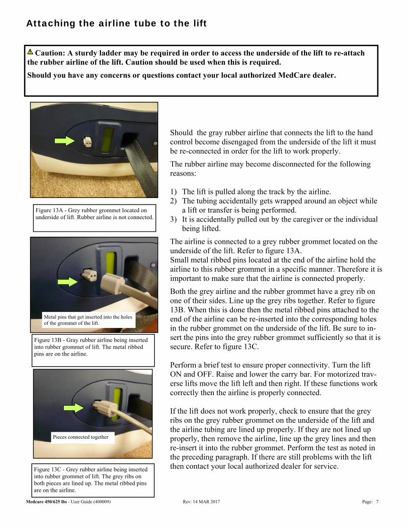
Should the gray rubber airline that connects the lift to the hand control become disengaged from the underside of the lift it must be re-connected in order for the lift to work properly.
The rubber airline may become disconnected for the following reasons: 1) The lift is pulled along the track by the airline. 2) The tubing accidentally gets wrapped around an object while
a lift or transfer is being performed. 3) It is accidentally pulled out by the caregiver or the individual
being lifted.
The airline is connected to a grey rubber grommet located on the underside of the lift. Refer to figure 13A. Small metal ribbed pins located at the end of the airline hold the airline to this rubber grommet in a specific manner. Therefore it is important to make sure that the airline is connected properly.
Both the grey airline and the rubber grommet have a grey rib on one of their sides. Line up the grey ribs together. Refer to figure 13B. When this is done then the metal ribbed pins attached to the end of the airline can be re-inserted into the corresponding holes in the rubber grommet on the underside of the lift. Be sure to in-sert the pins into the grey rubber grommet sufficiently so that it is secure. Refer to figure 13C. Perform a brief test to ensure proper connectivity. Turn the lift ON and OFF. Raise and lower the carry bar. For motorized trav-erse lifts move the lift left and then right. If these functions work correctly then the airline is properly connected. If the lift does not work properly, check to ensure that the grey ribs on the grey rubber grommet on the underside of the lift and the airline tubing are lined up properly. If they are not lined up properly, then remove the airline, line up the grey lines and then re-insert it into the rubber grommet. Perform the test as noted in the preceding paragraph. If there are still problems with the lift then contact your local authorized dealer for service.
Caution: A sturdy ladder may be required in order to access the underside of the lift to re-attach the rubber airline of the lift. Caution should be used when this is required.
Should you have any concerns or questions contact your local authorized MedCare dealer.
Figure 13A - Grey rubber grommet located on underside of lift. Rubber airline is not connected.
Figure 13B - Gray rubber airline being inserted into rubber grommet of lift. The metal ribbed pins are on the airline.
Metal pins that get inserted into the holes of the grommet of the lift.
Figure 13C - Grey rubber airline being inserted into rubber grommet of lift. The grey ribs on both pieces are lined up. The metal ribbed pins are on the airline.
Pieces connected together
Medcare 450/625 lbs - User Guide (400009) Rev: 14 MAR 2017 Page: 8
Caution: Always, before using the Medcare 450/625 lbs lift system, the lift, track and sling (s) must be visually checked for any unusual wear, or damage. Refer to the user manual with each piece of supplied equipment to determine what should be checked. Should anything look unusual contact your local Medcare dealer prior to use.
Failure to comply with this caution could result in serious injury to the operator, the in-dividual being lifted and/or damage to the lift.
Operation
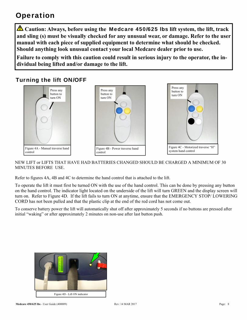
Turning the lift ON/OFF
Figure 4B - Power traverse hand control
Press any button to turn ON
Figure 4D - Lift ON indicator
Figure 4A - Manual traverse hand control
Press any button to turn ON
Figure 4C - Motorized traverse “H” system hand control
Press any button to turn ON
Figure 4E - Low battery indicator hand control
NEW LIFT or LIFTS THAT HAVE HAD BATTERIES CHANGED SHOULD BE CHARGED A MINIMUM OF 30 MINUTES BEFORE USE. Refer to figures 4A, 4B and 4C to determine the hand control that is attached to the lift.
To operate the lift it must first be turned ON with the use of the hand control. This can be done by pressing any button on the hand control. The indicator light located on the underside of the lift will turn GREEN and the display screen will turn on. Refer to Figure 4D. If the lift fails to turn ON at anytime, ensure that the EMERGENCY STOP/ LOWERING CORD has not been pulled and that the plastic clip at the end of the red cord has not come out.
To conserve battery power the lift will automatically shut off after approximately 5 seconds if no buttons are pressed after initial “waking” or after approximately 2 minutes on non-use after last button push.
Medcare 450/625 lbs - User Guide (400009) Rev: 14 MAR 2017 Page: 9
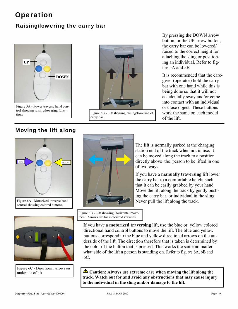
The lift is normally parked at the charging station end of the track when not in use. It can be moved along the track to a position directly above the person to be lifted in one of two ways.
If you have a manually traversing lift lower the carry bar to a comfortable height such that it can be easily grabbed by your hand. Move the lift along the track by gently push-ing the carry bar, or individual in the sling. Never pull the lift along the track.
If you have a motorized traversing lift, use the blue or yellow colored directional hand control buttons to move the lift. The blue and yellow buttons correspond to the blue and yellow directional arrows on the un-derside of the lift. The direction therefore that is taken is determined by the color of the button that is pressed. This works the same no matter what side of the lift a person is standing on. Refer to figures 6A, 6B and 6C.
Raising/lowering the carry bar
Operation
By pressing the DOWN arrow button, or the UP arrow button, the carry bar can be lowered/raised to the correct height for attaching the sling or position-ing an individual. Refer to fig-ure 5A and 5B
It is recommended that the care-giver (operator) hold the carry bar with one hand while this is being done so that it will not accidentally sway and/or come into contact with an individual or close object. These buttons work the same on each model of the lift.
Figure 5A - Power traverse hand con-trol showing raising/lowering func-tions
Moving the lift along
Figure 6A - Motorized traverse hand control showing colored buttons.
Figure 6C - Directional arrows on underside of lift
Figure 6B - Lift showing horizontal move-ment. Arrows are for motorized versions
Figure 5B - Lift showing raising/lowering of carry bar.
Caution: Always use extreme care when moving the lift along the track. Watch out for and avoid any obstructions that may cause injury to the individual in the sling and/or damage to the lift.
YELLOW
UP
DOWN
BLUE YELLOW
BLUE
Medcare 450/625 lbs - User Guide (400009) Rev: 14 MAR 2017 Page: 10
Operation Moving the “H” system traversing beam
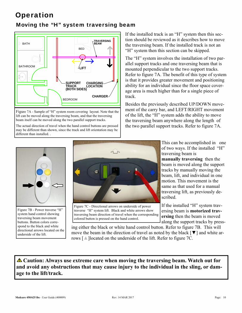
If the installed track is an “H” system then this sec-tion should be reviewed as it describes how to move the traversing beam. If the installed track is not an “H” system then this section can be skipped.
The “H” system involves the installation of two par-allel support tracks and one traversing beam that is mounted perpendicular to the two support tracks. Refer to figure 7A. The benefit of this type of system is that it provides greater movement and positioning ability for an individual since the floor space cover-age area is much higher than for a single piece of track.
Besides the previously described UP/DOWN move-ment of the carry bar, and LEFT/RIGHT movement of the lift, the “H” system adds the ability to move the traversing beam anywhere along the length of the two parallel support tracks. Refer to figure 7A.
Figure 7A - Sample of “H” system room covering layout. Note that the lift can be moved along the traversing beam, and that the traversing beam itself can be moved along the two parallel support tracks.
The actual direction of travel when the hand control buttons are pressed may be different than shown, since the track and lift orientation may be different than installed. .
BATHROOM
BEDROOM
BED
SUPPORTTRACK(BOTH SIDES)
BATHTRAVERSINGBEAM
LIFT
CHARGINGLOCATION
CHARGER
This can be accomplished in one of two ways. If the installed “H” traversing beam is manually traversing then the beam is moved along the support tracks by manually moving the beam, lift, and individual in one motion. This movement is the same as that used for a manual traversing lift, as previously de-scribed.
If the installed “H” system trav-ersing beam is motorized trav-ersing then the beam is moved along the support tracks by press-
ing either the black or white hand control button. Refer to figure 7B. This will move the beam in the direction of travel as noted by the black [▼] and white ar-rows [▲]located on the underside of the lift. Refer to figure 7C.
Figure 7C - Directional arrows on underside of power traverse “H” system lift. Black and white arrows show traversing beam direction of travel when the corresponding colored button is pressed on the hand control.
Figure 7B - Power traverse “H” system hand control showing traversing beam movement buttons. Button colors corre-spond to the black and white directional arrows located on the underside of the lift.
Caution: Always use extreme care when moving the traversing beam. Watch out for and avoid any obstructions that may cause injury to the individual in the sling, or dam-age to the lift/track.
Medcare 450/625 lbs - User Guide (400009) Rev: 14 MAR 2017 Page: 11
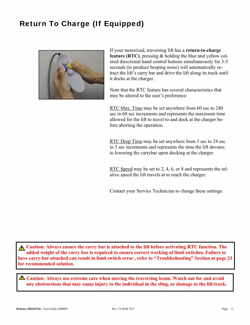
If your motorized, traversing lift has a return-to-charge feature (RTC), pressing & holding the blue and yellow col-ored directional hand control buttons simultaneously for 3-5 seconds (to produce beeping noise) will automatically re-tract the lift’s carry bar and drive the lift along its track until it docks at the charger. Note that the RTC feature has several characteristics that may be altered to the user’s preference:
RTC Max. Time may be set anywhere from 60 sec to 240 sec in 60 sec increments and represents the maximum time allowed for the lift to travel to and dock at the charger be-fore aborting the operation.
RTC Drop Time may be set anywhere from 3 sec to 24 sec in 3 sec increments and represents the time the lift devotes to lowering the carrybar upon docking at the charger.
RTC Speed may be set to 2, 4, 6, or 8 and represents the rel-ative speed the lift travels at to reach the charger.
Contact your Service Technician to change these settings.
Return To Charge (If Equipped)
Caution: Always ensure the carry bar is attached to the lift before activating RTC function. The added weight of the carry bar is required to ensure correct working of limit switches. Failure to
have carry bar attached can result in limit switch error , refer to “Troubleshooting” Section at page 21 for recommended solution.
Caution: Always use extreme care when moving the traversing beam. Watch out for and avoid any obstructions that may cause injury to the individual in the sling, or damage to the lift/track.
Medcare 450/625 lbs - User Guide (400009) Rev: 14 MAR 2017 Page: 12
Basics in transferring an individual
Caution: Always check to ensure that the lift is correctly positioned directly above the per-son to be lifted. Over time, the lift strap may fray if this is not followed.
Caution: Always make sure that the sling is correctly fitted and adjusted on each side of the individual so that maximum comfort and safety are achieved prior to lifting.
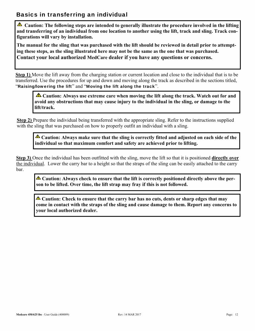
Step 1) Move the lift away from the charging station or current location and close to the individual that is to be transferred. Use the procedures for up and down and moving along the track as described in the sections titled, “Raising/lowering the lift” and “Moving the lift along the track”.
Step 3) Once the individual has been outfitted with the sling, move the lift so that it is positioned directly over the individual. Lower the carry bar to a height so that the straps of the sling can be easily attached to the carry bar.
Caution: The following steps are intended to generally illustrate the procedure involved in the lifting and transferring of an individual from one location to another using the lift, track and sling. Track con-figurations will vary by installation.
The manual for the sling that was purchased with the lift should be reviewed in detail prior to attempt-ing these steps, as the sling illustrated here may not be the same as the one that was purchased. Contact your local authorized MedCare dealer if you have any questions or concerns.
Step 2) Prepare the individual being transferred with the appropriate sling. Refer to the instructions supplied with the sling that was purchased on how to properly outfit an individual with a sling.
Caution: Always use extreme care when moving the lift along the track. Watch out for and avoid any obstructions that may cause injury to the individual in the sling, or damage to the lift/track.
Caution: Check to ensure that the carry bar has no cuts, dents or sharp edges that may come in contact with the straps of the sling and cause damage to them. Report any concerns to your local authorized dealer.
Medcare 450/625 lbs - User Guide (400009) Rev: 14 MAR 2017 Page: 13
Basics in transferring an individual … continued
Caution: Prior to lifting an individual make sure that the straps of the sling are securely placed on the hooks of the carry bar and that the straps will not come off.
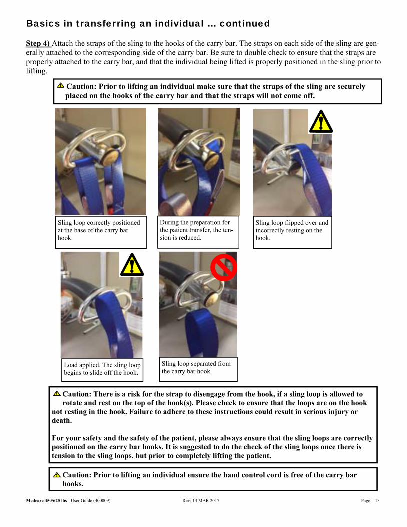
Step 4) Attach the straps of the sling to the hooks of the carry bar. The straps on each side of the sling are gen-erally attached to the corresponding side of the carry bar. Be sure to double check to ensure that the straps are properly attached to the carry bar, and that the individual being lifted is properly positioned in the sling prior to lifting.
Caution: There is a risk for the strap to disengage from the hook, if a sling loop is allowed to rotate and rest on the top of the hook(s). Please check to ensure that the loops are on the hook
not resting in the hook. Failure to adhere to these instructions could result in serious injury or death. For your safety and the safety of the patient, please always ensure that the sling loops are correctly positioned on the carry bar hooks. It is suggested to do the check of the sling loops once there is tension to the sling loops, but prior to completely lifting the patient.
Sling loop correctly positioned at the base of the carry bar hook.
During the preparation for the patient transfer, the ten-sion is reduced.
Sling loop flipped over and incorrectly resting on the hook.
Sling loop separated from the carry bar hook.
Load applied. The sling loop begins to slide off the hook.
Caution: Prior to lifting an individual ensure the hand control cord is free of the carry bar hooks.
Medcare 450/625 lbs - User Guide (400009) Rev: 14 MAR 2017 Page: 14
Basics in transferring an individual … continued
Caution: Prior to removing the straps of the sling from the carry bar be sure to check that the individual being lifted is securely supported in the final desired position.
Step 8) Lower the carry bar sufficiently to allow the straps of the sling to be easily removed from the carry bar. Take care not to let the carry bar come in contact with the individual in the sling. The straps from the sling can now be removed from the carry bar. The carry bar of the lift should then be raised sufficiently and the lift moved away from the immediate area so that it will not interfere with the removal of the sling from the indi-vidual.
Step 7) Once at the desired location the individual in the sling can be lowered/raised to the correct height in order to complete the transfer. On completion of lowering/raising ensure that the individual is properly posi-tioned and safely supported prior to removing the straps of the lift from the carry bar.
Step 6) Once at the correct height the individual can be moved along the track to the desired location. Refer to the sections already described in this manual on how to move the lift along the track
Step 10) The lift can now be moved to a safe location until further use, or relocated to its' original location. The lift should be turned off when not in use. It is recommended that the lift be left on charge when not in op-eration. Refer to the section titled, “Charging the lift” for instructions on charging.
Step 9 ) The sling can now be gently removed from the individual. It should then be stored in a safe place for future use.
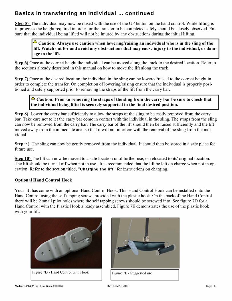
Optional Hand Control Hook Your lift has come with an optional Hand Control Hook. This Hand Control Hook can be installed onto the Hand Control using the self tapping screws provided with the plastic hook. On the back of the Hand Control there will be 2 small pilot holes where the self tapping screws should be screwed into. See figure 7D for a Hand Control with the Plastic Hook already assembled. Figure 7E demonstrates the use of the plastic hook with your lift.
Figure 7D - Hand Control with Hook Figure 7E - Suggested use
Step 5) The individual may now be raised with the use of the UP button on the hand control. While lifting is in progress the height required in order for the transfer to be completed safely should be closely observed. En-sure that the individual being lifted will not be injured by any obstructions during the initial lifting.
Caution: Always use caution when lowering/raising an individual who is in the sling of the lift. Watch out for and avoid any obstructions that may cause injury to the individual, or dam-age to the lift.
Medcare 450/625 lbs - User Guide (400009) Rev: 14 MAR 2017 Page: 15
The charger for the lift is mounted at the end of the track, usually away from wet areas such as a bath or pools. The charger would have been installed at the same time as the track and lift were installed.
The batteries should be charged on a regular basis. It is recommended that the lift be left on charge when not in operation, and at the end of each day. This will maximize the life cycle of the batteries
The lift may remain connected to the charger indefinitely since the charger has a built-in regulator, eliminating the danger of overcharging.
To charge the lift it is a simple matter of moving the lift to the end of the track where the charger is located. Refer to previously outlined sections on how to move the lift along the track. As a general rule it is recommended that the carry bar be raised to a height so that it will not interfere with anything or anyone.
Charging the lift
Figure 9A - Charger with ORANGE light indicating that the lift is connected and charging. When the lift is fully charged this light will turn GREEN.
In addition to the indicator lights on the lift, the charger has an indicator light. When ORANGE, it indicates that the lift is on the charger and charging. Refer to figure 9A.
When the light on the charger is GREEN, batteries are fully charged. Note: In some circumstances it may be necessary to mount the charger out of view.
Caution: For manually traversing lifts use caution when parking the lift into the charger. A slow speed should be used when close to the end of the track where the charger is located.
Caution: Use only the charger that was supplied with the lift. Use of any other charger will void all warran-ties and may cause damage to the lift. The lift can be charged when in the ON or OFF position.
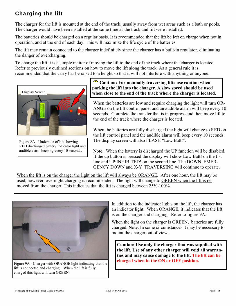
Figure 8A - Underside of lift showing RED discharged battery indicator light and audible alarm beeping every 10 seconds.
Display Screen
When the batteries are low and require charging the light will turn OR-ANGE on the lift control panel and an audible alarm will beep every 10 seconds. Complete the transfer that is in progress and then move lift to the end of the track where the charger is located. When the batteries are fully discharged the light will change to RED on the lift control panel and the audible alarm will beep every 10 seconds. The display screen will also FLASH “Low Batt!”. Note: When the battery is discharged the UP function will be disabled. If the up button is pressed the display will show Low Batt! on the fist line and UP:INHIBITED! on the second line. The DOWN, EMER-GENCY DOWN and X-Y TRAVERSING will continue to operate.
When the lift is on the charger the light on the lift will always be ORANGE. After one hour, the lift may be used, however, overnight charging is recommended. The light will change to GREEN when the lift is re-moved from the charger. This indicates that the lift is charged between 25%-100%.
Medcare 450/625 lbs - User Guide (400009) Rev: 14 MAR 2017 Page: 16
LCD Display Functionality
Default Display Modes:
The lift unit can be set to either of the following as the ‘Default’ display mode:
1. Battery Level (the factory setting for the Default Display Mode); or,
2. Number of Lifts.
To change from one operating mode to another please call your local service technician.
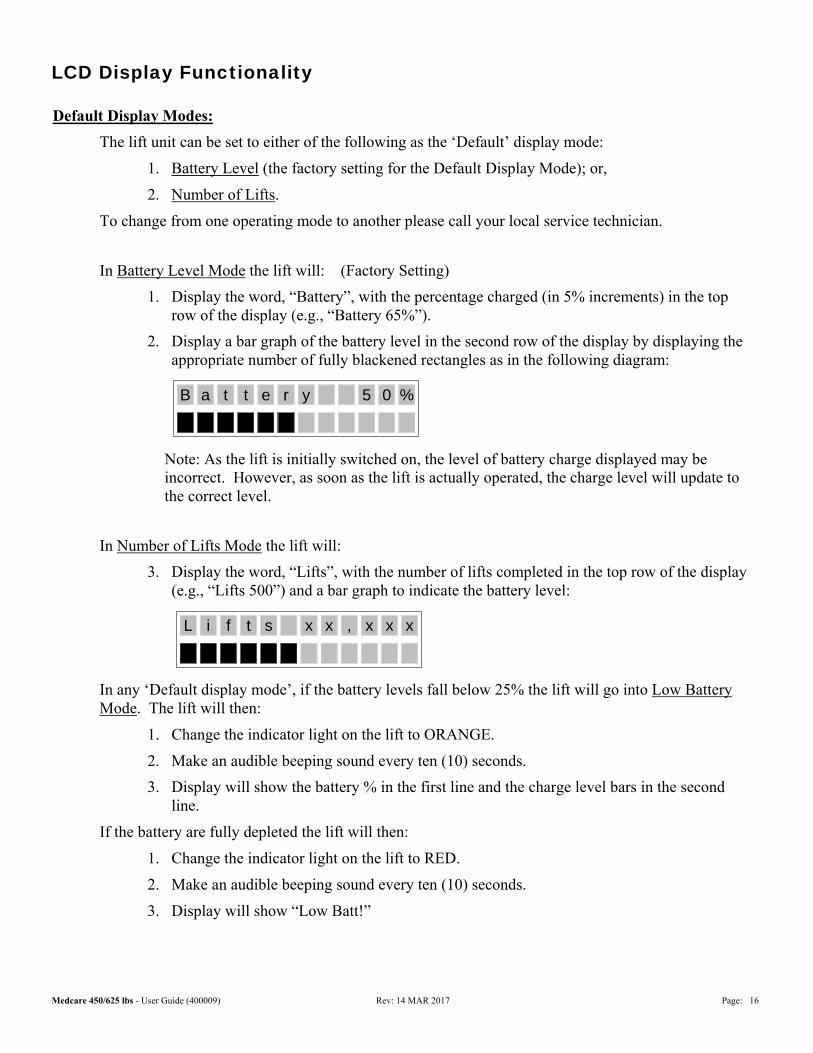
In Battery Level Mode the lift will: (Factory Setting)
1. Display the word, “Battery”, with the percentage charged (in 5% increments) in the top row of the display (e.g., “Battery 65%”).
2. Display a bar graph of the battery level in the second row of the display by displaying the appropriate number of fully blackened rectangles as in the following diagram:
Note: As the lift is initially switched on, the level of battery charge displayed may be incorrect. However, as soon as the lift is actually operated, the charge level will update to the correct level.
In Number of Lifts Mode the lift will:
3. Display the word, “Lifts”, with the number of lifts completed in the top row of the display (e.g., “Lifts 500”) and a bar graph to indicate the battery level:
In any ‘Default display mode’, if the battery levels fall below 25% the lift will go into Low Battery Mode. The lift will then:
1. Change the indicator light on the lift to ORANGE.
2. Make an audible beeping sound every ten (10) seconds.
3. Display will show the battery % in the first line and the charge level bars in the second line.
If the battery are fully depleted the lift will then:
1. Change the indicator light on the lift to RED.
2. Make an audible beeping sound every ten (10) seconds.
3. Display will show “Low Batt!”
%B a t e r y 05t
L i f s ,t x x x xx
Medcare 450/625 lbs - User Guide (400009) Rev: 14 MAR 2017 Page: 17
LCD Display Functionality
If the unit is in the charger the lift will go into Charging Display Mode regardless what the user has selected as ‘Default Display Mode’. Charging Display Mode will over-ride Low Battery Mode.
In Charging Display Mode the lift will:
1. Display “Charger” with the percentage charged (in 5% increments) in the top row of the display (e.g., “Charger 65%”).
Preventative Maintenance
The lift should recommend preventative maintenance if it hasn’t had any preventative maintenance for:
1. 1,000 lifts (this would equate to 4-5 lifts a day for 180 days); or,
2. 5 total hours of operation.
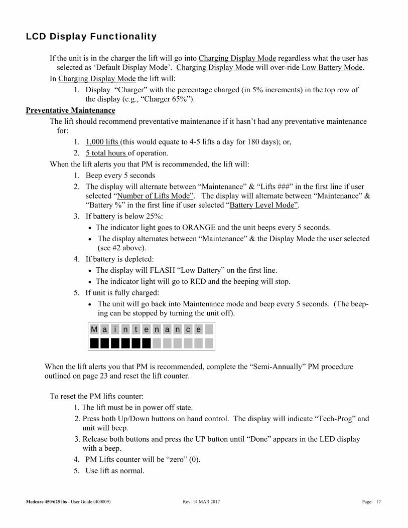
When the lift alerts you that PM is recommended, the lift will:
1. Beep every 5 seconds
2. The display will alternate between “Maintenance” & “Lifts ###” in the first line if user selected “Number of Lifts Mode”. The display will alternate between “Maintenance” & “Battery %” in the first line if user selected “Battery Level Mode”.
3. If battery is below 25%:
The indicator light goes to ORANGE and the unit beeps every 5 seconds.
The display alternates between “Maintenance” & the Display Mode the user selected (see #2 above).
4. If battery is depleted:
The display will FLASH “Low Battery” on the first line.
The indicator light will go to RED and the beeping will stop.
5. If unit is fully charged:
The unit will go back into Maintenance mode and beep every 5 seconds. (The beep-ing can be stopped by turning the unit off).
When the lift alerts you that PM is recommended, complete the “Semi-Annually” PM procedure outlined on page 23 and reset the lift counter.
To reset the PM lifts counter:
1. The lift must be in power off state.
2. Press both Up/Down buttons on hand control. The display will indicate “Tech-Prog” and unit will beep.
3. Release both buttons and press the UP button until “Done” appears in the LED display with a beep.
4. PM Lifts counter will be “zero” (0).
5. Use lift as normal.
M a i t e nn a n c e
Medcare 450/625 lbs - User Guide (400009) Rev: 14 MAR 2017 Page: 18
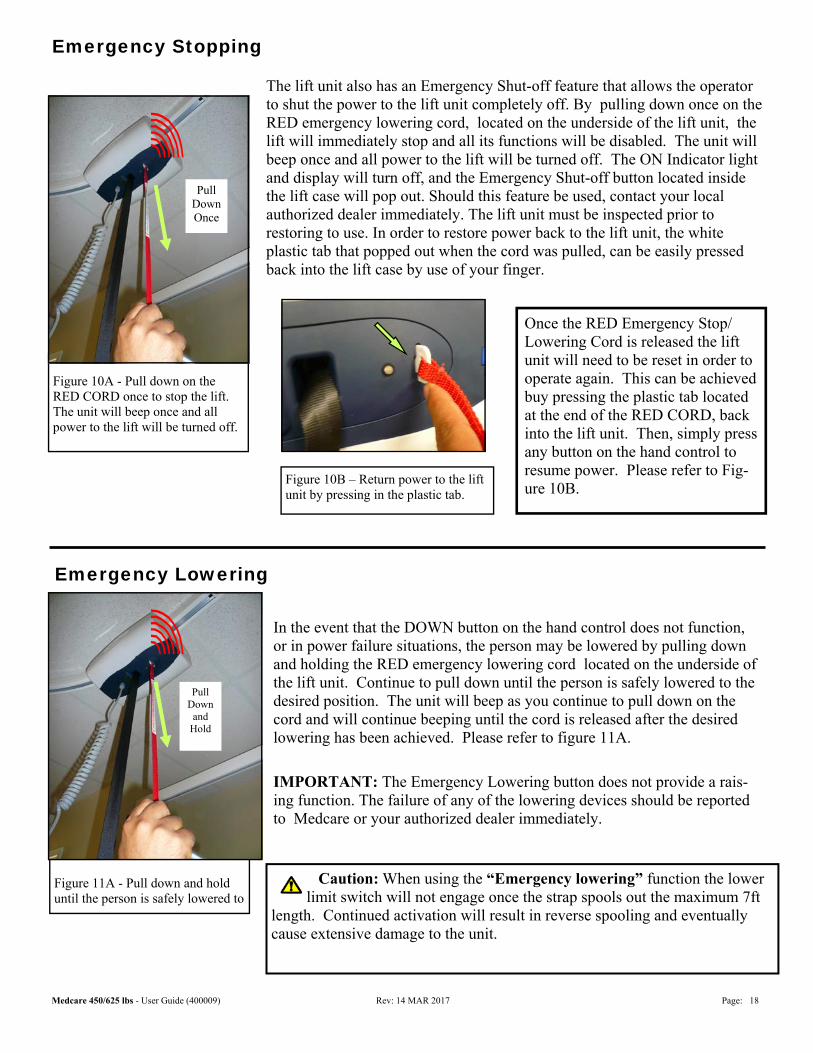
The lift unit also has an Emergency Shut-off feature that allows the operator to shut the power to the lift unit completely off. By pulling down once on the RED emergency lowering cord, located on the underside of the lift unit, the lift will immediately stop and all its functions will be disabled. The unit will beep once and all power to the lift will be turned off. The ON Indicator light and display will turn off, and the Emergency Shut-off button located inside the lift case will pop out. Should this feature be used, contact your local authorized dealer immediately. The lift unit must be inspected prior to restoring to use. In order to restore power back to the lift unit, the white plastic tab that popped out when the cord was pulled, can be easily pressed back into the lift case by use of your finger.
Emergency Stopping
In the event that the DOWN button on the hand control does not function, or in power failure situations, the person may be lowered by pulling down and holding the RED emergency lowering cord located on the underside of the lift unit. Continue to pull down until the person is safely lowered to the desired position. The unit will beep as you continue to pull down on the cord and will continue beeping until the cord is released after the desired lowering has been achieved. Please refer to figure 11A.
IMPORTANT: The Emergency Lowering button does not provide a rais-ing function. The failure of any of the lowering devices should be reported to Medcare or your authorized dealer immediately.
Figure 10A - Pull down on the RED CORD once to stop the lift. The unit will beep once and all power to the lift will be turned off.
Emergency Lowering
Figure 11A - Pull down and hold until the person is safely lowered to
Pull Down
and Hold
Figure 10B – Return power to the lift unit by pressing in the plastic tab.
Once the RED Emergency Stop/ Lowering Cord is released the lift unit will need to be reset in order to operate again. This can be achieved buy pressing the plastic tab located at the end of the RED CORD, back into the lift unit. Then, simply press any button on the hand control to resume power. Please refer to Fig-ure 10B.
Pull Down Once
Caution: When using the “Emergency lowering” function the lower limit switch will not engage once the strap spools out the maximum 7ft
length. Continued activation will result in reverse spooling and eventually cause extensive damage to the unit.
Medcare 450/625 lbs - User Guide (400009) Rev: 14 MAR 2017 Page: 19
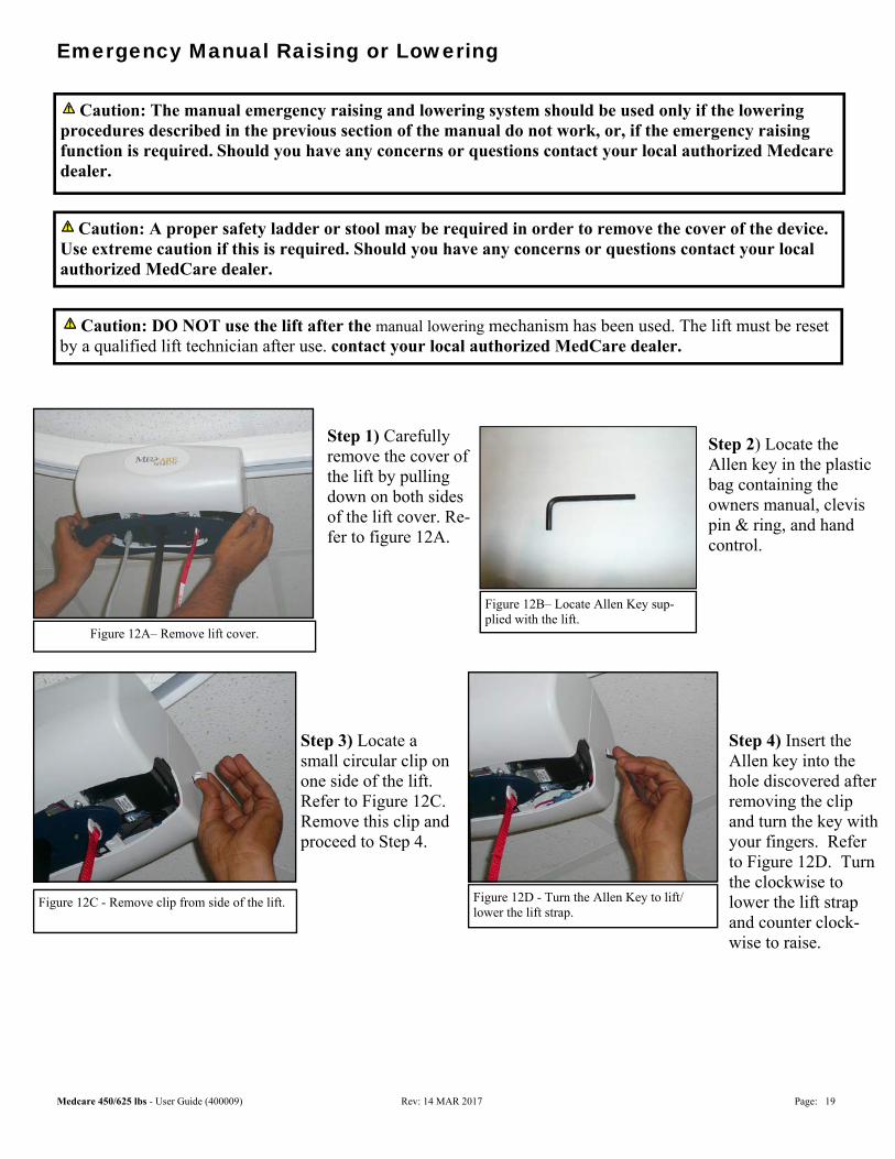
Emergency Manual Raising or Lowering
Caution: A proper safety ladder or stool may be required in order to remove the cover of the device. Use extreme caution if this is required. Should you have any concerns or questions contact your local authorized MedCare dealer.
Caution: The manual emergency raising and lowering system should be used only if the lowering procedures described in the previous section of the manual do not work, or, if the emergency raising function is required. Should you have any concerns or questions contact your local authorized Medcare dealer.
Figure 12A– Remove lift cover.
Step 1) Carefully remove the cover of the lift by pulling down on both sides of the lift cover. Re-fer to figure 12A.
Figure 12B– Locate Allen Key sup-plied with the lift.
Step 2) Locate the Allen key in the plastic bag containing the owners manual, clevis pin & ring, and hand control.
Step 3) Locate a small circular clip on one side of the lift. Refer to Figure 12C. Remove this clip and proceed to Step 4.
Figure 12C - Remove clip from side of the lift.
Step 4) Insert the Allen key into the hole discovered after removing the clip and turn the key with your fingers. Refer to Figure 12D. Turn the clockwise to lower the lift strap and counter clock-wise to raise.
Figure 12D - Turn the Allen Key to lift/ lower the lift strap.
Caution: DO NOT use the lift after the manual lowering mechanism has been used. The lift must be reset by a qualified lift technician after use. contact your local authorized MedCare dealer.
Medcare 450/625 lbs - User Guide (400009) Rev: 14 MAR 2017 Page: 20
Cleaning and Disinfection
The exterior of the lift should only be cleaned, disinfected using isopropyl alcohol. Damp a cloth with isopro-pyl alcohol and wipe down entire exterior of lift. No other chemicals and/or liquids should be used to clean and disinfect this lift. Caution: Take great care to ensure that no liquids get inside
the lift. This lift is not drip proof or water tight. Failure to protect the lift from liquids may result in damage to the lift and/or may cause personal injury.
The lift strap may be disinfected using Virox Accel TB RTU (Ready-to-use) available from: Virox Technologies Inc. 1-800-387-7578 www.virox.com
Details of Parts expected to come in contact with patients during Normal use
The following parts and accessories of C-625/C-450 that are intended to contact the patient in normal use. Sling (s). In rare instances contact of these parts are also possible (not deemed as applied parts ) Carry Bar. Hand Control.
Medcare 450/625 lbs - User Guide (400009) Rev: 14 MAR 2017 Page: 21
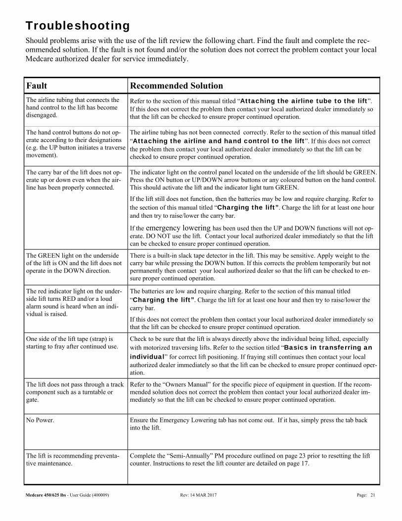
Fault Recommended Solution
The airline tubing that connects the hand control to the lift has become disengaged.
Refer to the section of this manual titled “Attaching the airline tube to the lift”. If this does not correct the problem then contact your local authorized dealer immediately so that the lift can be checked to ensure proper continued operation.
The hand control buttons do not op-erate according to their designations (e.g. the UP button initiates a traverse movement).
The airline tubing has not been connected correctly. Refer to the section of this manual titled “Attaching the airline and hand control to the lift”. If this does not correct the problem then contact your local authorized dealer immediately so that the lift can be checked to ensure proper continued operation.
The carry bar of the lift does not op-erate up or down even when the air-line has been properly connected.
The indicator light on the control panel located on the underside of the lift should be GREEN. Press the ON button or UP/DOWN arrow buttons or any coloured button on the hand control. This should activate the lift and the indicator light turn GREEN.
If the lift still does not function, then the batteries may be low and require charging. Refer to the section of this manual titled “Charging the lift”. Charge the lift for at least one hour and then try to raise/lower the carry bar.
If the emergency lowering has been used then the UP and DOWN functions will not op-erate. DO NOT use the lift. Contact your local authorized dealer immediately so that the lift can be checked to ensure proper continued operation.
The GREEN light on the underside of the lift is ON and the lift does not operate in the DOWN direction.
There is a built-in slack tape detector in the lift. This may be sensitive. Apply weight to the carry bar while pressing the DOWN button. If this corrects the problem temporarily but not permanently then contact your local authorized dealer so that the lift can be checked to en-sure proper continued operation.
The red indicator light on the under-side lift turns RED and/or a loud alarm sound is heard when an indi-vidual is raised.
The batteries are low and require charging. Refer to the section of this manual titled “Charging the lift”. Charge the lift for at least one hour and then try to raise/lower the carry bar.
If this does not correct the problem then contact your local authorized dealer immediately so that the lift can be checked to ensure proper continued operation.
One side of the lift tape (strap) is starting to fray after continued use.
Check to be sure that the lift is always directly above the individual being lifted, especially with motorized traversing lifts. Refer to the section titled “Basics in transferring an individual” for correct lift positioning. If fraying still continues then contact your local authorized dealer immediately so that the lift can be checked to ensure proper continued oper-ation.
The lift does not pass through a track component such as a turntable or gate.
Refer to the “Owners Manual” for the specific piece of equipment in question. If the recom-mended solution does not correct the problem then contact your local authorized dealer im-mediately so that the lift can be checked to ensure proper continued operation.
No Power. Ensure the Emergency Lowering tab has not come out. If it has, simply press the tab back into the lift.
The lift is recommending preventa-tive maintenance.
Complete the “Semi-Annually” PM procedure outlined on page 23 prior to resetting the lift counter. Instructions to reset the lift counter are detailed on page 17.
Troubleshooting Should problems arise with the use of the lift review the following chart. Find the fault and complete the rec-ommended solution. If the fault is not found and/or the solution does not correct the problem contact your local Medcare authorized dealer for service immediately.
Medcare 450/625 lbs - User Guide (400009) Rev: 14 MAR 2017 Page: 22
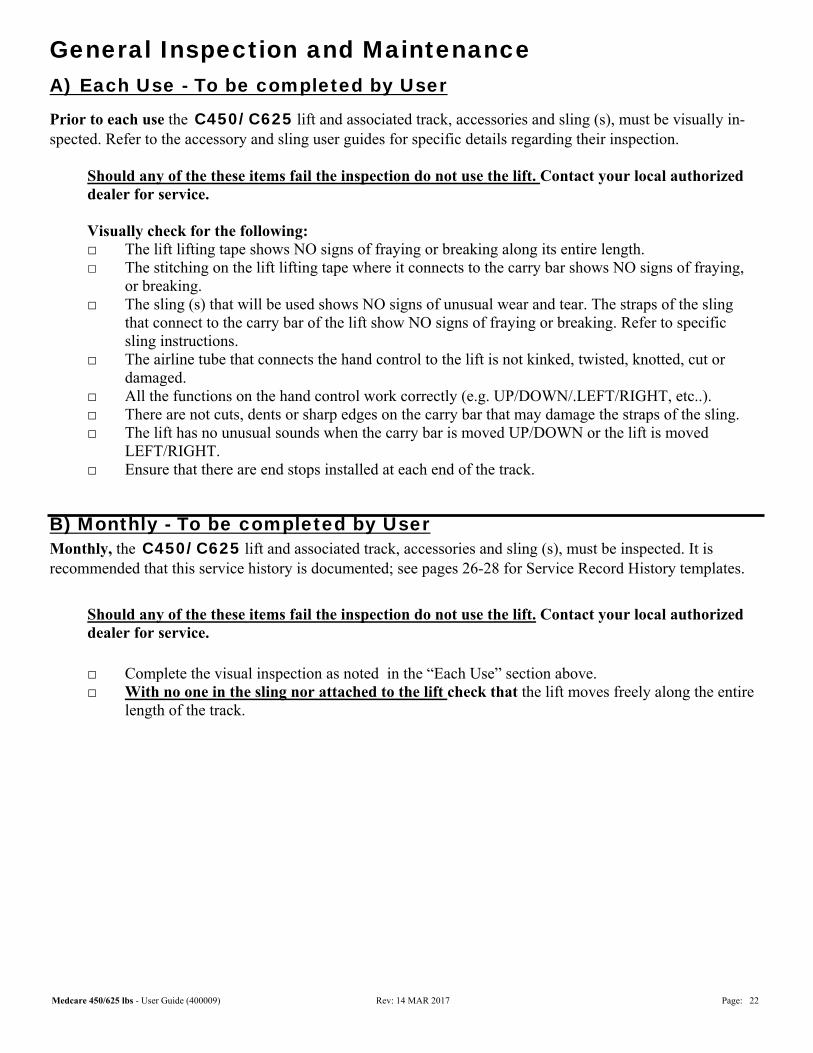
General Inspection and Maintenance A) Each Use - To be completed by User
Prior to each use the C450/ C625 lift and associated track, accessories and sling (s), must be visually in-spected. Refer to the accessory and sling user guides for specific details regarding their inspection. Should any of the these items fail the inspection do not use the lift. Contact your local authorized dealer for service. Visually check for the following: □ The lift lifting tape shows NO signs of fraying or breaking along its entire length. □ The stitching on the lift lifting tape where it connects to the carry bar shows NO signs of fraying, or breaking. □ The sling (s) that will be used shows NO signs of unusual wear and tear. The straps of the sling that connect to the carry bar of the lift show NO signs of fraying or breaking. Refer to specific sling instructions. □ The airline tube that connects the hand control to the lift is not kinked, twisted, knotted, cut or damaged. □ All the functions on the hand control work correctly (e.g. UP/DOWN/.LEFT/RIGHT, etc..). □ There are not cuts, dents or sharp edges on the carry bar that may damage the straps of the sling. □ The lift has no unusual sounds when the carry bar is moved UP/DOWN or the lift is moved LEFT/RIGHT. □ Ensure that there are end stops installed at each end of the track.
B) Monthly - To be completed by User Monthly, the C450/ C625 lift and associated track, accessories and sling (s), must be inspected. It is recommended that this service history is documented; see pages 26-28 for Service Record History templates.
Should any of the these items fail the inspection do not use the lift. Contact your local authorized dealer for service. □ Complete the visual inspection as noted in the “Each Use” section above. □ With no one in the sling nor attached to the lift check that the lift moves freely along the entire length of the track.
Medcare 450/625 lbs - User Guide (400009) Rev: 14 MAR 2017 Page: 23
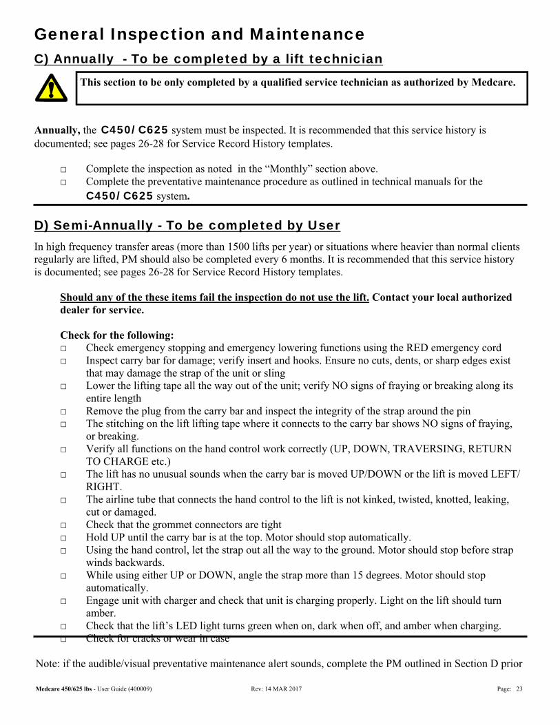
General Inspection and Maintenance C) Annually - To be completed by a lift technician
Annually, the C450/ C625 system must be inspected. It is recommended that this service history is documented; see pages 26-28 for Service Record History templates. □ Complete the inspection as noted in the “Monthly” section above. □ Complete the preventative maintenance procedure as outlined in technical manuals for the C450/ C625 system.
D) Semi-Annually - To be completed by User
In high frequency transfer areas (more than 1500 lifts per year) or situations where heavier than normal clients regularly are lifted, PM should also be completed every 6 months. It is recommended that this service history is documented; see pages 26-28 for Service Record History templates. Should any of the these items fail the inspection do not use the lift. Contact your local authorized dealer for service. Check for the following: □ Check emergency stopping and emergency lowering functions using the RED emergency cord □ Inspect carry bar for damage; verify insert and hooks. Ensure no cuts, dents, or sharp edges exist that may damage the strap of the unit or sling □ Lower the lifting tape all the way out of the unit; verify NO signs of fraying or breaking along its entire length □ Remove the plug from the carry bar and inspect the integrity of the strap around the pin □ The stitching on the lift lifting tape where it connects to the carry bar shows NO signs of fraying, or breaking. □ Verify all functions on the hand control work correctly (UP, DOWN, TRAVERSING, RETURN TO CHARGE etc.) □ The lift has no unusual sounds when the carry bar is moved UP/DOWN or the lift is moved LEFT/ RIGHT. □ The airline tube that connects the hand control to the lift is not kinked, twisted, knotted, leaking, cut or damaged. □ Check that the grommet connectors are tight □ Hold UP until the carry bar is at the top. Motor should stop automatically. □ Using the hand control, let the strap out all the way to the ground. Motor should stop before strap winds backwards. □ While using either UP or DOWN, angle the strap more than 15 degrees. Motor should stop automatically. □ Engage unit with charger and check that unit is charging properly. Light on the lift should turn amber. □ Check that the lift’s LED light turns green when on, dark when off, and amber when charging. □ Check for cracks or wear in case
Note: if the audible/visual preventative maintenance alert sounds, complete the PM outlined in Section D prior
This section to be only completed by a qualified service technician as authorized by Medcare.
Medcare 450/625 lbs - User Guide (400009) Rev: 14 MAR 2017 Page: 24
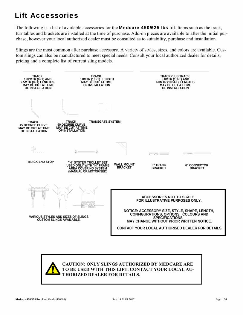
Lift Accessories The following is a list of available accessories for the Medcare 450/625 lbs lift. Items such as the track, turntables and brackets are installed at the time of purchase. Add-on pieces are available to after the initial pur-chase, however your local authorized dealer must be consulted as to suitability, purchase and installation. Slings are the most common after purchase accessory. A variety of styles, sizes, and colors are available. Cus-tom slings can also be manufactured to meet special needs. Consult your local authorized dealer for details, pricing and a complete list of current sling models.
WALL MOUNTBRACKET
VARIOUS STYLES AND SIZES OF SLINGS.CUSTOM SLINGS AVAILABLE.
TRACK END STOP
ACCESSORIES NOT TO SCALE. FOR ILLUSTRATIVE PURPOSES ONLY.
NOTICE: ACCESSORY SIZE, STYLE, SHAPE, LENGTH, CONFIGURATIONS, OPTIONS, COLOURS AND
SPECIFICATIONS MAY CHANGE WITHOUT PRIOR WRITTEN NOTICE.
CONTACT YOUR LOCAL AUTHORISED DEALER FOR DETAILS.
MULTI-PORT TURNTABLESYSTEM
TRANSGATE SYSTEM
"H" SYSTEM TROLLEY SETUSED ONLY WITH "H" FRAME
AREA COVERING SYSTEM(MANUAL OR MOTORISED)
3" TRACKBRACKET
QUICK FIT TURNTABLESYSTEM
6" CONNECTOR BRACKET
TRACK 1.82MTR (6FT) AND
2.5MTR (8FT) LENGTHS. MAY BE CUT AT TIME
OF INSTALLATION
TRACK 5.0MTR (16FT) LENGTHMAY BE CUT AT TIME
OF INSTALLATION
TRACK 45 DEGREE CURVE
MAY BE CUT AT TIMEOF INSTALLATION
TRACK 90 DEGREE CURVE
MAY BE CUT AT TIMEOF INSTALLATION
TRACKPLUS TRACK 5.0MTR (16FT) AND
6.0MTR (19.5FT) LENGTHS.MAY BE CUT AT TIME
OF INSTALLATION
CAUTION: ONLY SLINGS AUTHORIZED BY MEDCARE ARE TO BE USED WITH THIS LIFT. CONTACT YOUR LOCAL AU-THORIZED DEALER FOR DETAILS.
Medcare 450/625 lbs - User Guide (400009) Rev: 14 MAR 2017 Page: 25
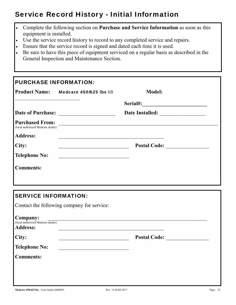
Service Record History - Initial Information
PURCHASE INFORMATION:
Product Name: Medcare 450/625 lbs lift Model: ____________________________ Serial#:________________________
Date of Purchase: _____________________ Date Installed: _________________
Purchased From: ___________________________________________________________ (local authorized Medcare dealer)
Address: _______________________________________
City: __________________________ Postal Code: ________________
Telephone No: __________________________ Comments:
Complete the following section on Purchase and Service Information as soon as this equipment is installed.
Use the service record history to record to any completed service and repairs. Ensure that the service record is signed and dated each time it is used. Be sure to have this piece of equipment serviced on a regular basis as described in the
General Inspection and Maintenance Section.
SERVICE INFORMATION:
Contact the following company for service: Company: ___________________________________________________________ (local authorized Medcare dealer)
Address: _______________________________________
City: __________________________ Postal Code: ________________
Telephone No: __________________________
Comments:

Medcare 450/625 lbs - User Guide (400009) Rev: 14 MAR 2017 Page: 26
Service Record History Complete this section after each service, repair inspection and/or maintenance. Photocopy additional pages as required.
Service Type: □ Periodic Inspection □ Monthly Inspection □ Semi-Annual Inspection □ Repair □ Yearly Inspection □ Other:_________
Completed By: _________________________ _____________________________ Printed Name Signature Company: _____________________________________________________________ Remarks & Action Taken:
Date: _______________________ Time: ________________________
Medcare 450/625 lbs - User Guide (400009) Rev: 14 MAR 2017 Page: 27
Service Record History Complete this section after each service, repair inspection and/or maintenance. Photocopy additional pages as required.
Service Type: □ Periodic Inspection □ Monthly Inspection □ Semi-Annual Inspection □ Repair □ Yearly Inspection □ Other:_________
Completed By: _________________________ _____________________________ Printed Name Signature Company: _____________________________________________________________ Remarks & Action Taken:
Date: _______________________ Time: ________________________
Service Type: □ Periodic Inspection □ Monthly Inspection □ Semi-Annual Inspection □ Repair □ Yearly Inspection □ Other:_________
Completed By: _________________________ _____________________________ Printed Name Signature Company: _____________________________________________________________ Remarks & Action Taken:
Date: _______________________ Time: ________________________
Service Type: □ Periodic Inspection □ Monthly Inspection □ Semi-Annual Inspection □ Repair □ Yearly Inspection □ Other:_________
Completed By: _________________________ _____________________________ Printed Name Signature Company: _____________________________________________________________ Remarks & Action Taken:
Date: _______________________ Time: ________________________
Service Type: □ Periodic Inspection □ Monthly Inspection □ Semi-Annual Inspection □ Repair □ Yearly Inspection □ Other:_________
Completed By: _________________________ _____________________________ Printed Name Signature Company: _____________________________________________________________ Remarks & Action Taken:
Date: _______________________ Time: ________________________
Service Type: □ Periodic Inspection □ Monthly Inspection □ Semi-Annual Inspection □ Repair □ Yearly Inspection □ Other:_________
Completed By: _________________________ _____________________________ Printed Name Signature Company: _____________________________________________________________ Remarks & Action Taken:
Date: _______________________ Time: ________________________
Service Type: □ Periodic Inspection □ Monthly Inspection □ Semi-Annual Inspection □ Repair □ Yearly Inspection □ Other:_________
Completed By: _________________________ _____________________________ Printed Name Signature Company: _____________________________________________________________ Remarks & Action Taken:
Date: _______________________ Time: ________________________

Medcare 450/625 lbs - User Guide (400009) Rev: 14 MAR 2017 Page: 28
Service Record History Complete this section after each service, repair inspection and/or maintenance. Photocopy additional pages as required.
Service Type: □ Periodic Inspection □ Monthly Inspection □ Semi-Annual Inspection □ Repair □ Yearly Inspection □ Other:_________
Completed By: _________________________ _____________________________ Printed Name Signature Company: _____________________________________________________________ Remarks & Action Taken:
Date: _______________________ Time: ________________________
Service Type: □ Periodic Inspection □ Monthly Inspection □ Semi-Annual Inspection □ Repair □ Yearly Inspection □ Other:_________
Completed By: _________________________ _____________________________ Printed Name Signature Company: _____________________________________________________________ Remarks & Action Taken:
Date: _______________________ Time: ________________________
Service Type: □ Periodic Inspection □ Monthly Inspection □ Semi-Annual Inspection □ Repair □ Yearly Inspection □ Other:_________
Completed By: _________________________ _____________________________ Printed Name Signature Company: _____________________________________________________________ Remarks & Action Taken:
Date: _______________________ Time: ________________________
Service Type: □ Periodic Inspection □ Monthly Inspection □ Semi-Annual Inspection □ Repair □ Yearly Inspection □ Other:_________
Completed By: _________________________ _____________________________ Printed Name Signature Company: _____________________________________________________________ Remarks & Action Taken:
Date: _______________________ Time: ________________________
Service Type: □ Periodic Inspection □ Monthly Inspection □ Semi-Annual Inspection □ Repair □ Yearly Inspection □ Other:_________
Completed By: _________________________ _____________________________ Printed Name Signature Company: _____________________________________________________________ Remarks & Action Taken:
Date: _______________________ Time: ________________________
Service Type: □ Periodic Inspection □ Monthly Inspection □ Semi-Annual Inspection □ Repair □ Yearly Inspection □ Other:_________
Completed By: _________________________ _____________________________ Printed Name Signature Company: _____________________________________________________________ Remarks & Action Taken:
Date: _______________________ Time: ________________________
Medcare 450/625 lbs - User Guide (400009) Rev: 14 MAR 2017 Page: 29
Warranty
This Warranty does not affect or in any way limit your Statutory Rights. 1. Medcare Products guarantees all equipment, which includes Ceiling Lifts, Floor Lifts, Slings, Service Parts
and Track and accessories, supplied as new, against failure within the period of 1 year from date of installation or 18 months from date of manufacturing, whichever is shorter, by virtue of defects in material or workmanship.
2. Medcare guarantees all refurbished equipment supplied against failure within a period of three months
from date of installation or six months from date of purchase whichever is shorter. 3. This guarantee does not apply to failure attributable to normal wear and tear, damage by natural forces,
user neglect or misuse or to deliberate destruction, or to batteries more than 90 days after original purchase. 4. This guarantee shall be void if the equipment is not serviced by Medcare Products or its authorized service
agents in accordance with the manufacturer’s recommendations or if any unauthorized person carries out works on the equipment.
5. The liability of Medcare Products under the terms of this guarantee shall be limited to the replacement of
defective parts and in no event shall Medcare Products incur liability for any consequential or unforeseeable losses.
If you have any questions about the manufacture or operation of this equipment, please contact
MedCare, or your local authorized dealer.
151 East Cliff Road, #10, Burnsville, MN 55337
1-800-695-4479 or 952-894-7076 www.medcarelifts.com
This document conforms to EN ISO 10535 requirements


![[XLS] mumbai employees... · Web viewShoppersstop- Crossword franchisee 3/71, Jolly Chambers, 1st nowroji Hill Road, Dongri, Mumbai-400009 Zafar Ahmed Sayyed jiz_126@yahoo.co.in 91-022-28550855](https://img.pdfslide.net/doc/110x75/5b0b11957f8b9a99488d3e40/xls-mumbai-employeesweb-viewshoppersstop-crossword-franchisee-371-jolly.jpg)