Embed Size (px)
Citation preview

N00052082.0October 27, 2005
Publication #:Document Release:
Release Date:
(Software Release 2.1)
Media Processing Server Series Platform Vendor Independent Components
Reference Manual

Important Notice
Nortel reserves the right to make changes in the contents of this publication including functions and specifications identified herein without notice.
The material contained in this document is intended for Nortel personnel and licensed customers with a non-disclosure agreement or standard contract.
In the absence of a written agreement to the contrary, Nortel assumes no liability for applications assistance, customer's product/application/concepts, or infringements of patents or copyrights of third parties arising from the use of systems and architectures described herein. Nor does Nortel warrant or represent that any license, either expressed or implied, is granted under any patent right, copyright, or other combination of technology, architecture, or software as might be or is already in use.
This document should not be reproduced, disseminated, or otherwise disclosed without prior written consent from an officer of Nortel.
This document has been copyrighted by Nortel and may not be duplicated.
Copyright © 2005 Nortel Networks, All Rights Reserved

Table of Contents
# N0005208 Ver: 2.0 Nortel Confidential Page 3
Table of Contents
Preface . . . . . . . . . . . . . . . . . . . . . . . . . . . . . . . . . . . . . . . . . . . . 7
Scope . . . . . . . . . . . . . . . . . . . . . . . . . . . . . . . . . . . . . . . . . . . . . . . 8Intended Audience . . . . . . . . . . . . . . . . . . . . . . . . . . . . . . . . . . . . . 8How to Use This Manual . . . . . . . . . . . . . . . . . . . . . . . . . . . . . . . . 9Organization of This Manual . . . . . . . . . . . . . . . . . . . . . . . . . . . . 10Conventions Used in This Manual . . . . . . . . . . . . . . . . . . . . . . . . 11Solaris 2.8 and Windows 2000 Conventions . . . . . . . . . . . . . . . . 12Trademark Conventions . . . . . . . . . . . . . . . . . . . . . . . . . . . . . . . . 12
Introduction . . . . . . . . . . . . . . . . . . . . . . . . . . . . . . . . . . . . . . 13
MPS Product Family . . . . . . . . . . . . . . . . . . . . . . . . . . . . . . . . . . 14Performance Statement . . . . . . . . . . . . . . . . . . . . . . . . . . . . . . . . 16
Hardware . . . . . . . . . . . . . . . . . . . . . . . . . . . . . . . . . . . . . . . . . 17
Hardware Requirements . . . . . . . . . . . . . . . . . . . . . . . . . . . . . . . 18Network Topology Diagrams . . . . . . . . . . . . . . . . . . . . . . . . . . . 18Common Hardware . . . . . . . . . . . . . . . . . . . . . . . . . . . . . . . . . . . 20
Ethernet Switch. . . . . . . . . . . . . . . . . . . . . . . . . . . . . . . . . . . 20MPS 500 Rear Panel . . . . . . . . . . . . . . . . . . . . . . . . . . . . . 20
Windows 2000-Specific Hardware . . . . . . . . . . . . . . . . . . . . . . . 21General Intel-based Windows Application Processor Specifications . . . . . . . . . . . . . . . . . . . . . . . . . . . . . . . . . . . . . 21Compatible Intel-based Windows Server Specifications . . . 22
1-RU Servers. . . . . . . . . . . . . . . . . . . . . . . . . . . . . . . . . . . 22IBM eServer X Series 335 . . . . . . . . . . . . . . . . . . . . 22IBM eServer X Series 336 . . . . . . . . . . . . . . . . . . . . 23HP DL360-G3. . . . . . . . . . . . . . . . . . . . . . . . . . . . . . 24HP DL360-G4. . . . . . . . . . . . . . . . . . . . . . . . . . . . . . 25
Desktops . . . . . . . . . . . . . . . . . . . . . . . . . . . . . . . . . . . . . . 26HP ML330-G3 . . . . . . . . . . . . . . . . . . . . . . . . . . . . . 26Compaq d530 . . . . . . . . . . . . . . . . . . . . . . . . . . . . . . 27
MPS 500 25-RU Cabinet with Windows APs . . . . . . . . . . . 28Hardware Cabling . . . . . . . . . . . . . . . . . . . . . . . . . . . . . . . . . 30
Serial Console Connection Requirement . . . . . . . . . . . . . 30Customer-Supplied Modem . . . . . . . . . . . . . . . . . . . . . . . . . 30
Solaris 2.8-Specific Hardware . . . . . . . . . . . . . . . . . . . . . . . . . . . 31Compatible Solaris Servers. . . . . . . . . . . . . . . . . . . . . . . . . . 31
Application Processors . . . . . . . . . . . . . . . . . . . . . . . . . . . 31V120 Sun Fire . . . . . . . . . . . . . . . . . . . . . . . . . . . . . . 31V210 Sun Fire . . . . . . . . . . . . . . . . . . . . . . . . . . . . . . 32V240 Sun Fire . . . . . . . . . . . . . . . . . . . . . . . . . . . . . . 32Netra 240. . . . . . . . . . . . . . . . . . . . . . . . . . . . . . . . . . 33

Media Processing Server Series PVI Components Reference Manual
Page 4 Nortel Confidential # N0005208 Ver: 2.0
Workstation. . . . . . . . . . . . . . . . . . . . . . . . . . . . . . . . . . . . 35Sun Blade 150. . . . . . . . . . . . . . . . . . . . . . . . . . . . . . 35
MPS 500 25 RU Cabinet with Sun Fire V210 . . . . . . . . . . . 36Terminal Server . . . . . . . . . . . . . . . . . . . . . . . . . . . . . . . . . . 38
Windows 2000 Information . . . . . . . . . . . . . . . . . . . . . . . . . . 39
Software Requirements and System Configuration . . . . . . . . . . . 40Windows 2000 Overview . . . . . . . . . . . . . . . . . . . . . . . . . . . . . . 40
Third-party Software Guidelines . . . . . . . . . . . . . . . . . . . . . 41Postinstallation Packages . . . . . . . . . . . . . . . . . . . . . . . . . . . 42Windows 2000 Software. . . . . . . . . . . . . . . . . . . . . . . . . . . . 43
Mandatory Software . . . . . . . . . . . . . . . . . . . . . . . . . . . . . 43Customer-Supplied Software . . . . . . . . . . . . . . . . . . 43MPS CD Software . . . . . . . . . . . . . . . . . . . . . . . . . . 43
Permitted Software . . . . . . . . . . . . . . . . . . . . . . . . . . . . . . 44Operating System Patches . . . . . . . . . . . . . . . . . . . . . . . . 45
Recommended Disk Partitioning . . . . . . . . . . . . . . . . . . . . . 45
Solaris 2.8 Information . . . . . . . . . . . . . . . . . . . . . . . . . . . . . 47
Software Requirements and System Configuration . . . . . . . . . . . 48Solaris 2.8 Overview . . . . . . . . . . . . . . . . . . . . . . . . . . . . . . . . . . 48Software Specifications . . . . . . . . . . . . . . . . . . . . . . . . . . . . . . . . 49
Required Software . . . . . . . . . . . . . . . . . . . . . . . . . . . . . . . . 49Customer-Supplied Software . . . . . . . . . . . . . . . . . . . . . . 49Nortel MPS Software . . . . . . . . . . . . . . . . . . . . . . . . . . . . 49
Recommended Software . . . . . . . . . . . . . . . . . . . . . . . . . . . . 49Installation Overview . . . . . . . . . . . . . . . . . . . . . . . . . . . . . . . . . . 50Solaris 2.8 Installation Procedure . . . . . . . . . . . . . . . . . . . . . . . . 52
Step 1: Install Solaris 2.8 . . . . . . . . . . . . . . . . . . . . . . . . . . . 52Verify the Operating System . . . . . . . . . . . . . . . . . . . . . . 52Obtain Solaris 2.8 . . . . . . . . . . . . . . . . . . . . . . . . . . . . . . . 53Format and Partition the Disk. . . . . . . . . . . . . . . . . . . . . . 54
Disk Partition Sizes. . . . . . . . . . . . . . . . . . . . . . . . . . 54Formatting and Partitioning Guidelines . . . . . . . . . . 55Format Menu. . . . . . . . . . . . . . . . . . . . . . . . . . . . . . . 58Format Partition Menu . . . . . . . . . . . . . . . . . . . . . . . 59
Installing Solaris 2.8 . . . . . . . . . . . . . . . . . . . . . . . . . . . . . 60Step 2: Install Solaris Patches . . . . . . . . . . . . . . . . . . . . . . . . 80Step 3: Reboot. . . . . . . . . . . . . . . . . . . . . . . . . . . . . . . . . . . . 82Step 4: Set Network Lookup to Use Files. . . . . . . . . . . . . . . 83Step 5: Run PVI Check. . . . . . . . . . . . . . . . . . . . . . . . . . . . . 85Step 6: Install Java . . . . . . . . . . . . . . . . . . . . . . . . . . . . . . . . 86Step 7: Install VNC. . . . . . . . . . . . . . . . . . . . . . . . . . . . . . . . 88Step 8: Install Netscape Browser . . . . . . . . . . . . . . . . . . . . . 89Step 9: Check Directories and Mount Points . . . . . . . . . . . . 90
Table of Contents
# N0005208 Ver: 2.0 Nortel Confidential Page 5
Special Considerations . . . . . . . . . . . . . . . . . . . . . . . . . . . 90Configuring the Filesystem for /mmf . . . . . . . . . . . . . . . . 91
A: Mount a slice onto the File System . . . . . . . . . . . 91B: Use root Filesystem . . . . . . . . . . . . . . . . . . . . . . . 91C: Link to Another Filesystem . . . . . . . . . . . . . . . . . 92
Configuring the Filesystem for /opt . . . . . . . . . . . . . . . . . 93A: Identify a Filesystem for /opt. . . . . . . . . . . . . . . . 93B: Link /opt/vps to a Filesystem. . . . . . . . . . . . . . . . 94C: Create the /opt/bin Directory . . . . . . . . . . . . . . . . 94
Step 10: Turn on LOM (Lights Out Management). . . . . . . . 95Step 11: Disable Power Management . . . . . . . . . . . . . . . . . . 96Step 12: Configure the ASE System Requirements . . . . . . . 97Step 13: Create User peri Environment . . . . . . . . . . . . . . . . 98
Step 13A: Create /home directory for User peri . . . . . . 98Step 13B: Link /home Directory for User peri . . . . . . . . 99Step 13C: Create the User and Group peri . . . . . . . . . . . 99Step 13D: Create a Password for peri . . . . . . . . . . . . . . 100
Step 14: Change the Reboot Scripts . . . . . . . . . . . . . . . . . . 101Step 15: Install Nortel Core and Patch Software . . . . . . . . 102
Install Nortel Core Software . . . . . . . . . . . . . . . . . . . . . . 102Install Nortel Patch Software . . . . . . . . . . . . . . . . . . . . . 102Terminating Applications and Services . . . . . . . . . . . . . 103
Step 16: Confirm Installation with perirev command . . 104Step 17: Postinstallation Steps . . . . . . . . . . . . . . . . . . . . . . 105Step 18: Configure the MPS . . . . . . . . . . . . . . . . . . . . . . . . 106Step 19: Run SRP Status Report. . . . . . . . . . . . . . . . . . . . . 107Step 20: Perform Field Factory Test. . . . . . . . . . . . . . . . . . 108
Security Hardening . . . . . . . . . . . . . . . . . . . . . . . . . . . . . . . . . . 109
Testing . . . . . . . . . . . . . . . . . . . . . . . . . . . . . . . . . . . . . . . . . . 111
Testing and Validation . . . . . . . . . . . . . . . . . . . . . . . . . . . . . . . . 112PVI Check . . . . . . . . . . . . . . . . . . . . . . . . . . . . . . . . . . . . . . . . . 112PVI Check on the Windows 2000 Platform . . . . . . . . . . . . . . . . 113
Minimum Required Hardware . . . . . . . . . . . . . . . . . . . . . . 113Optional Hardware . . . . . . . . . . . . . . . . . . . . . . . . . . . . . 113
PVI Check Results . . . . . . . . . . . . . . . . . . . . . . . . . . . . . . . 114PVI Check Execution . . . . . . . . . . . . . . . . . . . . . . . . . . . . . 115
PVI Check on the Solaris 2.8 Platform . . . . . . . . . . . . . . . . . . . 117PVI Check Execution . . . . . . . . . . . . . . . . . . . . . . . . . . . . . 117PVI Check Results . . . . . . . . . . . . . . . . . . . . . . . . . . . . . . . 117
Service Description . . . . . . . . . . . . . . . . . . . . . . . . . . . . . . . . 121
Overview . . . . . . . . . . . . . . . . . . . . . . . . . . . . . . . . . . . . . . . . . . 122Sample Service Description for IVR Systems . . . . . . . . . . . . . . 122

Media Processing Server Series PVI Components Reference Manual
Page 6 Nortel Confidential # N0005208 Ver: 2.0
Installation Road . . . . . . . . . . . . . . . . . . . . . . . . . . . . . . . . . 131
Maps . . . . . . . . . . . . . . . . . . . . . . . . . . . . . . . . . . . . . . . . . . . 131
PVI Installation Road Maps Overview . . . . . . . . . . . . . . . . . . . 132Prerequisites for a PVI Installation . . . . . . . . . . . . . . . . . . . . . . 133
Preinstallation Checklist . . . . . . . . . . . . . . . . . . . . . . . . . . . 133Rerun PVI Check . . . . . . . . . . . . . . . . . . . . . . . . . . . . . . . . 133
Field Factory Test . . . . . . . . . . . . . . . . . . . . . . . . . . . . . . . . . . . 134Windows 2000 PERIfft Package . . . . . . . . . . . . . . . . . . . . 134Solaris 2.8 PERIfft Package . . . . . . . . . . . . . . . . . . . . . . . . 135
PVI Road Map #1: MPS Software on a Windows Platform . . . 136PVI Road Map #2: MPS Software on a Solaris Platform . . . . . 138PVI Road Map #3: Speech Server Installation . . . . . . . . . . . . . 140PVI Road Map #4: CDD Installation . . . . . . . . . . . . . . . . . . . . . 143PVI Road Map #5: PAF Installation . . . . . . . . . . . . . . . . . . . . . 146PVI Road Map #6: Installing PAF on a WVADS Workstation 148
Index . . . . . . . . . . . . . . . . . . . . . . . . . . . . . . . . . . . . . . . . . . . 149

Preface
Media Processing Server Series PVI Components Reference Manual
Page 8 Nortel Confidential #N0005208 Ver. 2.0
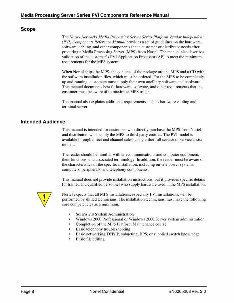
ScopeThe Nortel Networks Media Processing Server Series Platform Vendor Independent (PVI) Components Reference Manual provides a set of guidelines on the hardware, software, cabling, and other components that a customer or distributor needs after procuring a Media Processing Server (MPS) from Nortel. The manual also describes validation of the customer’s PVI Application Processor (AP) to meet the minimum requirements for the MPS system.
When Nortel ships the MPS, the contents of the package are the MPS and a CD with the software installation files, which must be ordered. For the MPS to be completely up and running, customers must supply their own ancillary software and hardware. This manual documents best fit hardware, software, and other requirements that the customer must be aware of to maximize MPS usage.
The manual also explains additional requirements such as hardware cabling and terminal server.
Intended AudienceThis manual is intended for customers who directly purchase the MPS from Nortel, and distributors who supply the MPS to third-party entities. The PVI model is available through direct and channel sales, using either full service or service assist models.
The reader should be familiar with telecommunications and computer equipment, their functions, and associated terminology. In addition, the reader must be aware of the characteristics of the specific installation, including on-site power systems, computers, peripherals, and telephony components.
This manual does not provide installation instructions, but it provides specific details for trained and qualified personnel who supply hardware used in the MPS installation.
! Nortel expects that all MPS installations, especially PVI installations, will be performed by skilled technicians. The installation technicians must have the following core competencies as a minimum.
• Solaris 2.8 System Administration • Windows 2000 Professional or Windows 2000 Server system administration • Completion of the MPS Platform Maintenance course • Basic telephony troubleshooting • Basic networking TCP/IP, subneting, BPS, or supplied switch knowledge • Basic file editing

Preface
#N0005208 Ver. 2.0 Nortel Confidential Page 9
How to Use This ManualThis manual uses many standard terms relating to computer system and software application functions. However, it contains some terminology that can only be explained in the context of the MPS. Refer to the Nortel Glossary of MPS Terminology for definitions of these types of terms.
If you are reading this document online, use the cross-reference links (shown in blue) to quickly locate related topics. Click once with your mouse while positioned with your cursor over the cross-reference link. Click on any point in a Table of Contents entry to move to that topic. Click on the page number of any Index entry to access that topic page.
For additional related information, use the Reference Material link in PeriDoc. To become familiar with various specialized text conventions used within the manual, see Conventions Used in This Manual on page 11.
Periphonics is now part of Nortel. The name Periphonics, and variations thereof, may appear in this manual where it refers specifically to certain product names and commands. For example, a PeriProducer application, the PERImps package, the perirev command, and so on.

Media Processing Server Series PVI Components Reference Manual
Page 10 Nortel Confidential #N0005208 Ver. 2.0
Organization of This ManualThis section briefly outlines the structure of this manual.
Chapter 1 - Introduction
Introduces the Nortel MPS Series, and describes various MPS offerings. This chapter also outlines the contents of an MPS shipment, and describes what a customer requires to ensure the MPS is functioning.
Chapter 2 - Hardware
Provides information on the different kinds of hardware that the customer must provide to complement the functioning of the Nortel-supplied MPS.
Chapter 3 - Windows 2000 Information
Lists and describes all software that is installed on the MPS AP and required configuration for Windows 2000.
Chapter 4 - Solaris 2.8 Information
Lists and describes all software that is installed on the MPS AP, installation instructions and required configuration for Solaris 2.8.
Chapter 5 - Testing
Describes validation of the customer’s PVI AP to meet the minimum requirements for the MPS system.
Chapter 6 - Service Description
Provides a description and example of Nortel’s support services.
Appendix A - Installation Road Maps
Provides checklists for various PVI installation scenarios.

Preface
#N0005208 Ver. 2.0 Nortel Confidential Page 11
Conventions Used in This ManualThis manual uses different fonts and symbols to differentiate between document elements and types of information. These conventions are summarized in the following table.
Conventions Used in This Manual
Notation Description
Normal text Normal text font is used for most of the document.
important term The Italics font is used to introduce new terms, highlight meaningful words or phrases, or distinguish specific terms from nearby text.
system command
This font indicates system commands and arguments. Such keywords must be entered exactly as shown (that is, users must not fill in their own values).
file name / directory
This font is used for highlighting the names of disk directories, files, and extensions for file names. It is also used to show displays on text-based screens (for example, to show the contents of a file.)
on-screen field This font is used for field labels, on-screen menu buttons, and action buttons.
<KEY NAME> A term that appears within angled brackets denotes a terminal keyboard key, a telephone keypad button, or a system mouse button.
Book Reference This font indicates the names of other publications referenced within the document.
cross-reference A cross-reference is shown on the screen in blue. Click on the cross-reference to access the referenced location. A cross-reference that refers to a section name accesses the first page of that section.
The Note icon identifies notes, important facts, and other keys to understanding.
!The Caution icon identifies procedures or events that require special attention. The icon indicates a warning that serious problems may arise if the stated instructions are improperly followed.
The flying Window icon identifies procedures or events that apply to the Windows operating system only. (1)
The Solaris icon identifies procedures or events that apply to the Solaris operating system only. (2)
(1): Windows and the flying Window logo are either trademarks or registered trademarks of the Microsoft Corporation.
(2): Solaris is a trademark or registered trademark of Sun Microsystems, Inc. in the United States and other countries.

Media Processing Server Series PVI Components Reference Manual
Page 12 Nortel Confidential #N0005208 Ver. 2.0
Solaris 2.8 and Windows 2000 ConventionsThis manual depicts examples (command line syntax, configuration files, and screen shots) in Solaris format. In certain instances, Windows 2000-specific commands, procedures, or screen shots are shown where required. The following table lists examples of general operating system conventions to keep in mind when using this manual with either the Solaris 2.8 or Windows 2000 operating system.
Trademark ConventionsThe following trademark information is presented here and applies throughout this publication for discussions of third-party products. Trademark information is not repeated hereafter.
Solaris is a trademark or registered trademark of Sun Microsystems, Inc. in the United States and other countries.
Microsoft, Windows, Internet Explorer, and the Flying Windows logo are either trademarks or registered trademarks of Microsoft Corporation.
Netscape® and the Netscape N® and Ship's Wheel® logos are registered trademarks of Netscape Communications Corporation in the U.S. and other countries. Netscape Navigator is also a trademark of Netscape Communications Corporation and may be registered outside the U.S.
Solaris 2.8 Windows 2000
Environment $MPSHOME %MPSHOME%
Paths $MPSHOME/common/etc %MPSHOME%\common\etc
Command <command> & start /b <command>

This chapter covers:
Introduction
1. MPS Product Family
2. Performance Statement

Media Processing Server Series PVI Components Reference Manual
Page 14 Nortel Confidential #N0005208 Ver: 2.0
MPS Product Family
The MPS Series Product Line consists of hardware and software for performing Inter-active Voice Response (IVR) and media processing functions in call processing envi-ronments. The MPS specifically integrates call processing components with speech, telephony, data communications and transaction processing functions.
The MPS is available in the following configurations:
MPS 500 - Consists of one Telephony Media Server (TMS), which supports eight T1/ E1 spans or VoIP channels of comparable capacity. T1 supports 192 ports, while the E1 supports 240 ports. MPS 500 is available on the Windows 2000 and Solaris 2.8 platforms.
MPS 1000 - The MPS 1000 is available only on the Solaris 2.8 platform, and provides automated transaction handling and application-controlled call handling in an inte-grated, non-blocking system. The MPS 1000 supports comprehensive networking and data communication.
The MPS 1000 supports 96 to 9216 T1 ports, 120 to 11520 E1 or VoIP ports or a com-bination of digital and VoIP connections in a single system.
The MPS 500 and MPS 1000 provide options to write self-service applications using the following tools:
• PeriProducer — graphical development tool
• VoiceXML — text-based markup language
The Nortel MPS shipment typically includes a CD with all of the essential software (Nortel software, non-operating system software, and third-party software) required to bring the MPS into functional mode. In addition to the MPS and requisite software, customers using the MPS solution must supply the following:
Hardware Requirements — This includes the application processor (AP), memory, hard disk space, modem or VPN for remote support, ports, network interface cards, and connectivity details. The following hardware is considered optional:
• Monitor
• Keyboard
• Mouse
• Media servers:
• Speech Server
• IPML
• CCT
• IAS
• SIP
Introduction
#N0005208 Ver: 2.0 Nortel Confidential Page 15
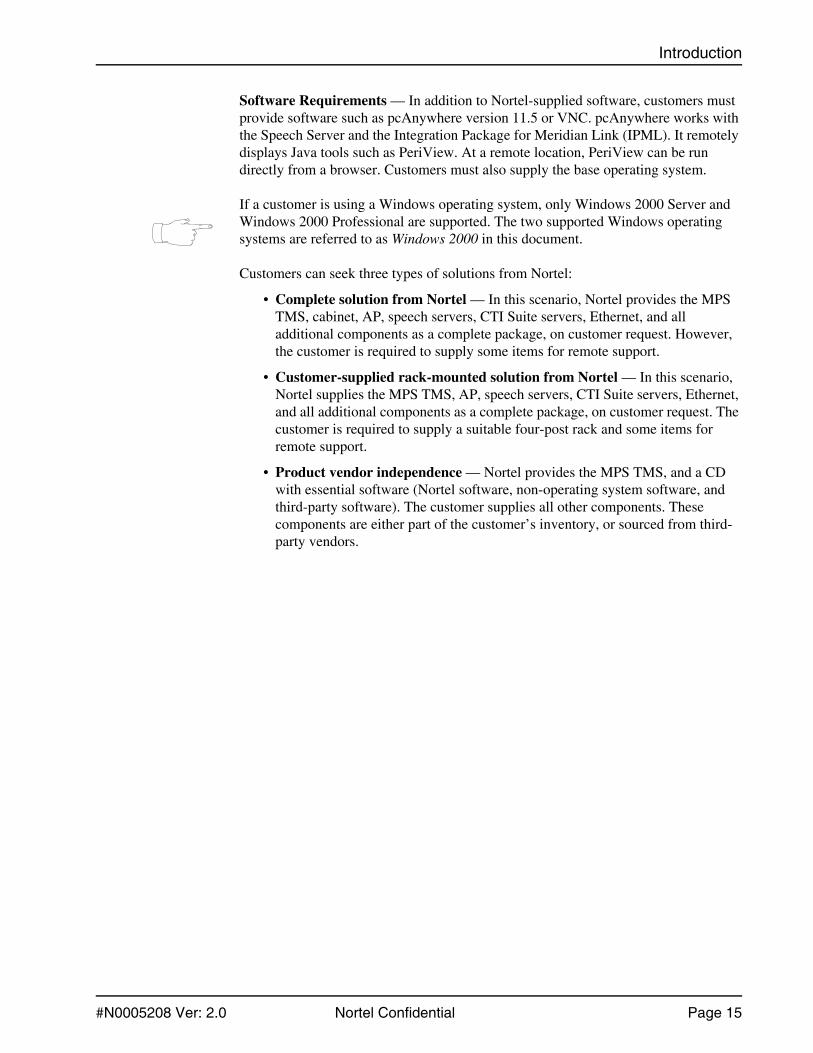
Software Requirements — In addition to Nortel-supplied software, customers must provide software such as pcAnywhere version 11.5 or VNC. pcAnywhere works with the Speech Server and the Integration Package for Meridian Link (IPML). It remotely displays Java tools such as PeriView. At a remote location, PeriView can be run directly from a browser. Customers must also supply the base operating system.
If a customer is using a Windows operating system, only Windows 2000 Server and Windows 2000 Professional are supported. The two supported Windows operating systems are referred to as Windows 2000 in this document.
Customers can seek three types of solutions from Nortel:
• Complete solution from Nortel — In this scenario, Nortel provides the MPS TMS, cabinet, AP, speech servers, CTI Suite servers, Ethernet, and all additional components as a complete package, on customer request. However, the customer is required to supply some items for remote support.
• Customer-supplied rack-mounted solution from Nortel — In this scenario, Nortel supplies the MPS TMS, AP, speech servers, CTI Suite servers, Ethernet, and all additional components as a complete package, on customer request. The customer is required to supply a suitable four-post rack and some items for remote support.
• Product vendor independence — Nortel provides the MPS TMS, and a CD with essential software (Nortel software, non-operating system software, and third-party software). The customer supplies all other components. These components are either part of the customer’s inventory, or sourced from third-party vendors.

Media Processing Server Series PVI Components Reference Manual
Page 16 Nortel Confidential #N0005208 Ver: 2.0
Performance Statement
The number of channels that run on an MPS AP is directly determined by application quality and design. XML, SSL, JSB, VXML and CCXML, by nature, may require sig-nificant MPS AP and memory resources. This is not an exhaustive list, as many other factors such as inefficient application design, excessive system calls, and deeply nested dialogues may also affect AP performance.
When Nortel provides a turnkey solution that includes all hardware and applications, Nortel accepts responsibility for the performance of the solution. When either PVI hardware or application is part of the solution and is provided by a third party, Nortel accepts responsibility only for the performance of the portion of the solution that Nortel supplies.
Therefore, Nortel strongly recommended that pilot and load tests be performed with all applications. Test results may lead to a requirement to optimize the application code or purchase additional APs and hardware, or both.
This chapter covers:
Hardware
1. Hardware Requirements
2. Network Topology Diagrams
3. Common Hardware
4. Windows 2000-Specific Hardware
5. Solaris 2.8-Specific Hardware

Media Processing Server Series PVI Components Reference Manual
Page 18 Nortel Confidential #N0005208 Ver: 2.0
Hardware Requirements
The different kinds of hardware that the customer must provide to complement the functioning of the Nortel-supplied MPS are described below. These requirements are applicable to the MPS AP, Speech Server, and IPML. Information in this chapter has been separated for Windows 2000 and Solaris 2.8.
Network Topology Diagrams
The following MPS 500 2.1 network topology diagrams show different components and the connections between them.
Figure 1: MPS 500 Basic Network Diagram with Ethernet Switch

Hardware
#N0005208 Ver: 2.0 Nortel Confidential Page 19
Figure 2: MPS 500 Network Diagram with Ethernet Switch (SIP)
Figure 3: MPS 500 Network Diagram with Ethernet Switch (H.323)
Media Processing Server Series PVI Components Reference Manual
Page 20 Nortel Confidential #N0005208 Ver: 2.0
Common Hardware
The following hardware is common to both Windows 2000 and Solaris 2.8 platforms.
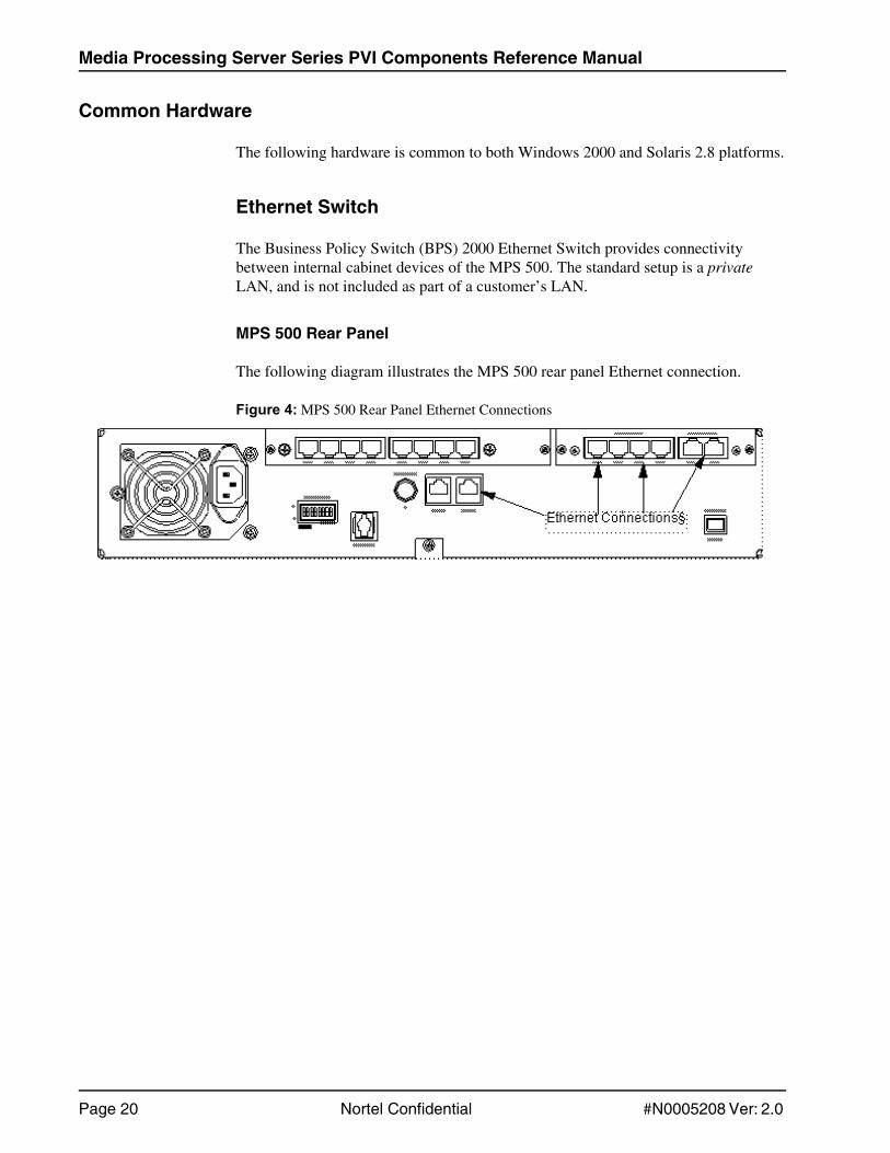
Ethernet Switch
The Business Policy Switch (BPS) 2000 Ethernet Switch provides connectivity between internal cabinet devices of the MPS 500. The standard setup is a private LAN, and is not included as part of a customer’s LAN.
MPS 500 Rear Panel
The following diagram illustrates the MPS 500 rear panel Ethernet connection.
Figure 4: MPS 500 Rear Panel Ethernet Connections
Hardware
#N0005208 Ver: 2.0 Nortel Confidential Page 21
Windows 2000-Specific Hardware
The following hardware requirements are applicable to Windows 2000 systems.
General Intel-based Windows Application Processor Specifications
This server is used for the MPS Application Processor, Speech Server, and CTI Servers.
This server has the following features:
• Dual Xeon @ 2.8 GHz w/512 k L2 cache
• 512k L2 cache recommended
• 1 GB RAM (DDR) minimum, 2 GB recommended
• 36 GB SCSI hard disk
• CD-ROM
• Two 10/ 100/ 1000 Mbps Network Interface Cards
• One Serial Port
• Modem or VPN connectivity (VPN is preferred). The Nortel Contivity VPN is recommended.
• Video keyboard and mouse
The following features are optional:
• Customer-supported backup hardware
• Hot-swappable disks and RAID level 1 are recommended. Network backup solutions can also be used at the customer’s discretion.
• Audio — supported on PeriProducer and PeriStudio

Media Processing Server Series PVI Components Reference Manual
Page 22 Nortel Confidential #N0005208 Ver: 2.0
Compatible Intel-based Windows Server Specifications
The following Intel-based servers have been tested by Nortel and have been found to be compatible with MPS as Application Processors, Speech Servers and CTI Servers. Each tested server was running Windows 2000 Professional with Service Pack 4.
1-RU Servers
The following 1-RU servers are compatible with the MPS.
IBM eServer X Series 335
The following table shows the eServer X Series 335 components and specifications.
Table 1: IBM eServer X Series 335 Components and Specifications
Components Specifications
Processor Intel Xeon(tm) Processor 3.2 GHz/2MB
Memory 2 GB (2x1024)
Drive Cage Two 1" Ultra 320 SCSI Hot Plug Drive Bays
RAID Setting RAID 1 Setting
1st Hard drive 36.4 GB Pluggable Ultra 320 SCSI 10,000 rpm Universal HDD (1")
2nd Hard drive 36.4 GB Pluggable Ultra 320 SCSI 10,000 rpm Universal HDD (1")
Storage Controller Smart Array 5i Plus Controller (integrated on system board)
Floppy Disk Drive 1.44 MB Floppy Disk Drive
CD-ROM/DVD Slim Line CD/RW/DVD-ROM 24x Combo Drive
Network Card Two NC7781 PCI-X Gbit NICs (embedded) 10/100/1000 WOL
Power Supply 325 Watt Power Supply

Hardware
#N0005208 Ver: 2.0 Nortel Confidential Page 23
IBM eServer X Series 336
The following table shows the eServer X Series 336 components and specifications.
Table 2: IBM eServer X Series 336 Components and Specifications
Components Specifications
Processor Dual Intel Xeon(tm) Processor 3.6 GHz
Memory 1GB PC2-3200 DDR2
RAID Setting RAID 1 and 1E Settings
Hard Drive 73 Gb SCSI HDD(s)
Storage Controller Smart Array 5i Plus Controller (integrated on system board)
Floppy Disk Drive 1.44 MB Floppy Disk Drive
CD-ROM/DVD Slim Line CD/RW/DVD-ROM 24x Combo Drive
Network Card Integrated Dual 10/100/1000 Ethernet
Power Supply 585 W dual Power Supply
Warranty three-year, on-site limited warranty

Media Processing Server Series PVI Components Reference Manual
Page 24 Nortel Confidential #N0005208 Ver: 2.0
HP DL360-G3
The following table shows the HP DL360-G3 Server components and specifications.
Table 3: HP DL360-G3 Components and Specifications
Components Specifications
Processor Intel Xeon(tm) Processor 3.2 GHz/2MB
Memory 2 GB (2x1024)
Drive Cage Two 1" Wide Ultra 320 SCSI Hot Plug Drive Bays
RAID Setting RAID 1 Setting
1st Hard Drive 36.4 GB Pluggable Ultra320 SCSI 10000 rpm Universal HDD (1")
2nd Hard Drive 36.4 GB Pluggable Ultra320 SCSI 10000 rpm Universal HDD (1")
Storage Controller Smart Array 5i Plus Controller (integrated on system board)
Floppy Disk Drive 1.44 MB Floppy Disk Drive
CD-ROM Slim Line CD/RW/DVD-ROM 24x Combo Drive
Network Card Two NC7781 PCI-X Gigabit NICs (embedded) 10/100/1000 WOL
Redundant Power Supply Redundant 325 Watt Hot Plug Power Supply (1+1 redundancy)
Warranty Three years, next business day, on-site

Hardware
#N0005208 Ver: 2.0 Nortel Confidential Page 25
HP DL360-G4
The following table shows the HP DL360-G4 Server components and specifications.
Table 4: HP DL360-G4 Components and Specifications
Components Specifications
Processor Dual Intel Xeon(tm) Processor 3.6 GHz
Memory 1 GB PC2-3200 DDR2
Hard Drive 73 GB SCSI HDD(s)
Drive Cage Two 1" Ultra 320 SCSI Hot Plug Drive Bays
RAID Setting RAID 1 and 1E Settings
Storage Controller Embedded Smart Array 6i RAID Controller
Floppy Disk Drive 1.44 MB Floppy Disk Drive
CD-ROM Slim Line CD/RW/DVD-ROM 24x Combo Drive
Network Card HP NC7782 Dual Port PCI-X Gigabit
Redundant Power Supply 460-Watt hot plug power supply with optional 1+1 redundancy
Warranty Three-years parts, labor, and on-site

Media Processing Server Series PVI Components Reference Manual
Page 26 Nortel Confidential #N0005208 Ver: 2.0
Desktops
HP ML330-G3
The following table shows the HP ML330-G3 desktop server components and specifi-cations.
Table 5: HP ML330-G3 Components and Specifications
Components Specifications
Processor Intel Xeon(tm) Processor 3.06GHz/ 533MB FSB
Memory 1GB Total PC2100 Registered ECC DDR SDRAM (2 x 512)
Storage Controller Integrated Single Channel Ultra 3 SCSI Adapter in a PCI slot
1st Hard Drive 36 GB Ultra 320 SCSI 10,000 rpm Non-Hot Plug HDD (1")
2nd Hard Drive 36 GB Ultra 320 SCSI 10,000 rpm Non-Hot Plug HDD (1") (free with server purchase)
Floppy Disk Drive 1.44 MB Floppy Disk Drive
CD-ROM/DVD High Speed IDE CD-ROM Drive
Network Card Compaq NC7760 PCI Gbit Server Adapter (Integrated/Embedded)
Additional Network Card HP NC7170 Dual Port PCI-X 1000T Gbit Server Adapter
Warranty One-year, next business day, on-site

Hardware
#N0005208 Ver: 2.0 Nortel Confidential Page 27
Compaq d530
The following table shows the Compaq d530 desktop server components and specifi-cations.
Table 6: Compaq d530 Components and Specifications
Components Specifications
Operating System Windows 2000
Processor Intel Pentium 4 Processor 3.2 GHz/ 800 MB w/HT Technology
Memory 1GB DDR PC3200 Non-ECC (DDDR400) SDRAM (2 x 512)
Graphics Controller nVIDIA GeForce MX-440-8 64 MB DDR FH 8XAGP VGA
1st Hard Drive 80 GB Serial ATA 7200 rpm HDD
Floppy Disk Drive 1.44 MB Floppy Disk Drive
CD-ROM/DVD 8x DVD+R/+RW Drive
Mouse HP PS/2 ball scroll mouse
Keyboard HP PS/2 keyboard easy access KBD
Network Card Broadcom NetXtreme Gbit Ethernet
Warranty Three years parts and labour, with three year next business day on-site

Media Processing Server Series PVI Components Reference Manual
Page 28 Nortel Confidential #N0005208 Ver: 2.0
MPS 500 25-RU Cabinet with Windows APs
The following figures show sample MPS 500 configurations. This is a maximum con-figuration for reference only. For exact configuration, consult your SDP.
Figure 5: Front Panel Configuration
MPS 500 Enclosure (RJ48x/VoIP), VxC
MPS 500 TMS, T1/E1/VoIP, Speech Enabled[VoIP/SS7 Intrfc Crd]
[MPS 500 TMS, DSP Exp Crd] [TMS# 2]
MPS 500 Enclosure (RJ48x/VoIP), VxCMPS 500 TMS, T1/E1/VoIP, Speech Enabled
[VoIP/SS7 Intrfc Crd]
[MPS 500 TMS, DSP Exp Crd] [TMS# 1]
[Rear Access: 24 port Ethernet Switch]
MPS Server/Speech Server, Keyboard/Video/Mouse Assy, VAC
IBM X335, 115/230 VAC [Server/Speech Server# 9]
[IBM X335, 1GB Mem, IBM X335, Recovery Disk]
IBM X335, 115/230 VAC [Server/Speech Server# 8]
[IBM X335, 1GB Mem , IBM X335, Recovery Disk]
IBM X335, 115/230 VAC [Server/Speech Server# 7]
[IBM X335, 1GB Mem, IBM X335, Recovery Disk]
IBM X335, 115/230 VAC [Server/Speech Server# 6]
[IBM X335, 1GB Mem, IBM X335, Recovery Disk]
IBM X335, 115/230 VAC [Server/Speech Server# 5][IBM X335, 1GB Mem, IBM X335, Recovery Disk]
IBM X335, 115/230 VAC [Server/Speech Server# 4][IBM X335, 1GB Mem, IBM X335, Recovery Disk]
IBM X335, 115/230 VAC [Server/Speech Server# 3][IBM X335, 1GB Mem, IBM X335, Recovery Disk]
IBM X335, 115/230 VAC [AP/ Server/Speech Server# 2][IBM X335, 1GB Mem, IBM X335, Recovery Disk]
IBM X335, 115/230 VAC [Application Processor #1]
[IBM X335, 1GB Mem, IBM X335, Recovery Disk]

Hardware
#N0005208 Ver: 2.0 Nortel Confidential Page 29
Figure 6: Rear Panel Configuration
(EMEA Only) MPS TCCP Balun, E1, 75ohm Coax
24 port Ethernet Switch
Media Processing Server Series PVI Components Reference Manual
Page 30 Nortel Confidential #N0005208 Ver: 2.0
Hardware Cabling
This section provides basic information about attaching peripheral devices to the server. These devices include:
• Monitor
• Keyboard/ mouse
• Pointing device
Serial Console Connection Requirement
The MPS 500 is shipped with a serial console cable, which is used for programming the TMS. The PVI PC end of the provided cable is an RJ45 connector. However, if the PVI PC has a different connector, then the customer must provide the required cable adapter for the RJ45.
Customer-Supplied Modem
Windows-based servers may not provide sufficient power to source most non-pow-ered external USB modems. In cases where a USB modem is required, a commer-cially viable powered USB modem should be feasible.
Nortel does not endorse any specific model of the powered USB modem. Nortel has successfully tested the use of a powered USB hub such as the Belkin Model # F5U021 Four Port Hub or equivalent. Many USB modems are consumer grade and are cheaply constructed products. Nortel has tested several USB modems connected both directly and through a self powered hub. The only USB modem tested that demonstrated a high reliability and consistent performance was the Multitech #MT5634ZBA-USB. Other consumer grade USB modems failed in three out of five test sites due to erratic behavior. In each test, the Multitech USB modem performed flawlessly.
The problems encountered with most USB modems Nortel tested were related to poor quality phone line interfaces and excessive sensitivity to noise. These characteristics will likely be present in many consumer grade Serial Port modems as well. The Multitech MT5634-ZDX Serial port modem demonstrated the same high quality performance as the USB version. The use of any brand of Internal/PCI based modem is not recommended because Nortel has not tested any Internal/PCI based modem.
USB modems are not supported on SUN platforms.
For instructions on installing a modem, refer to the Nortel Media Processing Server 500 Hardware Installation and Maintenance Manual.

Hardware
#N0005208 Ver: 2.0 Nortel Confidential Page 31
Solaris 2.8-Specific Hardware
The following hardware requirements are applicable to Solaris 2.8 systems.
Compatible Solaris Servers
The following Solaris Servers have been tested by Nortel and have been found to be compatible with MPS as application processors and workstations. Each tested server was running Solaris 2.8.
Application Processors
The following APs are applicable to Solaris. The minimum drive size is 36 GB and a CD drive is required for all processors. For each AP, Nortel recommends 1 GB of memory per CPU.
V120 Sun Fire
The Sun FireTM V120 is a one-rack unit (RU) server with one processor. It has the following features:
• One UltraSPARC IIi Processor (550 or 650 MHz)
• PC133 DIMM slots (4 GB maximum)
• Dual Ethernet/Fast Ethernet, STP (10 Base-T and 100 Base-T)
• One Ultra 2 SCSI port
• Two RJ-45 serial ports
• Two USB ports
• Optional 8x speed DVD-ROM drive and 40x speed CD-ROM drive
• Up to two 18 or 36 GB SCSI hard disk drives
• System configuration card
• Front and back service indicators
• Lights-Out Manager
• PCI Expansion - 1x32-bit, 33 MHz
• Single AC power supply

Media Processing Server Series PVI Components Reference Manual
Page 32 Nortel Confidential #N0005208 Ver: 2.0
V210 Sun Fire
The Sun FireTM V210 is a one-rack unit (RU) server with two processors. It has the following features:
• Two UltraSPARC IIIi Processors
• Four DDR-1 SDRAM (PC2100) DIMM slots per processor
• Four 10/100/1000 Base-T Ethernet ports
• One Ultra 160 SCSI port
• One RJ-45 serial port for server management
• One DB-9 general purpose serial port
• Two USB ports
• One 10Base-T Management Port
• Optional DVD-ROM drive
• Two Ultra 160 SCSI hard disk drives
• System configuration card
• Front and back service indicators
• Advanced Lights-Out Manager
• PCI Expansion - 1x64-bit, 33/66 MHz, 3.3V PCI slot
• Single AC power supply
V240 Sun Fire
The V240 is based on SPARC and Solaris architecture. It is a dual-processor-capable, rack-optimized server. The main features of the V240 are listed below:
• Two UltraSPARC IIIi processors
• 8 GB of memory
• Four disks
• Four Gigabit Ethernet ports
• Three PCI slots
• Two redundant power supplies
• One system configuration card

Hardware
#N0005208 Ver: 2.0 Nortel Confidential Page 33
Netra 240
The Netra 240 is a two-rack unit (RU) server that uses either one or two UltraSPARC® IIIi processors. Two hot-swappable disk drives provide storage, along with an optional non-hot-swappable slimline DVD-RW or DVD-ROM drive. Four GB Ethernet channels and two SCSI channels (one for external use and the other for internal use) provide built-in I/O functionality. Two open host controller interface (OHCI) USB hubs are also provided.
One full-length PCI card slot that supports both 33 MHz and 66 MHz cards and two half-length PCI card slots that support 33 MHz cards provide I/O expansion. A dry contact relay alarm card for Remote Management Control (RMC) firmware and an alarm status LEDs card are also provided. The Netra 240 has the following features:
• One- to two-way UltraSPARC IIIi processor
• Telcordia NEBS compliant (DC server only)
• Two redundant (1+1) 400 W power supplies
• Four DIMM slots per processor
• Four 10/100/1000BASE-T Gigabit Ethernet ports
• Two SCSI channels (one for external use and one for internal use)
• Up to two SCSI hard disk drives available on an internal SCSI channel
• One DB-9 serial port and one RJ-45 serial port for remote management control (RMC)
• One 10BASE-T management port for RMC
• Two USB ports
• Three PCI expansion slots (one full length and two half length)
• DVD-RW or DVD-ROM drive (optional component)
• System Configuration Card (SCC)
• Front and back system status indicators
• Advanced Lights Out Manager (ALOM) software
• Dry contact relay alarms with alarm indicators
• Cooling blowers and a replaceable air filter

Media Processing Server Series PVI Components Reference Manual
Page 34 Nortel Confidential #N0005208 Ver: 2.0
The following hardware is also recommended for the Netra 240:
• At least two network cards — one for the Nortel LAN, and the other for the customer LAN
• CD drive
• Tape drive, or access to a network tape drive, for backup purposes
• Serial terminal server for local console access and modem for remote support. However, if the terminal server comes equipped with a modem, it can perform both functions.

Hardware
#N0005208 Ver: 2.0 Nortel Confidential Page 35
Workstation
The following Workstation is applicable to Solaris.
Sun Blade 150
The Sun Blade 150 workstation is a uniprocessor system that uses the UltraSPARC IIi processor. The system has the following features:
• Desktop-style system enclosure
• 250-watt power supply
• 1 GB RAM
• CPU options — 550 MHz or 650 MHz UltraSPARC IIi processor with 512 Kbyte internal cache, heatsink, and fan
• Hard drives:
• One 40 GB, 7,200 RPM hard drive with ATA66 interface
• Additional hard drive available as an optional component
• Smart card reader
• Optical drive — CD-ROM or DVD-ROM
• Audio — CD quality
• PCI connectors:
• 33 MHz, 32-bit Peripheral Component Interconnect (PCI)
• Three long PCI connectors that accept both long and short PCI cards
• ATI Rage XL on board graphics, 8 MB RAM
• Two serial ports
• One port on the chassis back panel
• One port on the riser card (requires one PCI slot to access the connector)
• One parallel port
• Ethernet — 10 megabit/100 megabit per second
• Two IEEE 1394 ports (Firewire)
• Four USB ports (two are required for keyboard and mouse)
• Keyboard — Sun TM USB Type-6 AT 101 layout
• Mouse — Sun USB three-button, crossbow mouse
The Sun Blade 150 can also be used as an AP. However, it may not be able to support eight spans under all application conditions due to lack of processing power. Nortel does not recommend the Sun Blade 150 as an application processor for more than four spans in DTMF applications. The Sun Blade 150 cannot be used as an application pro-cessor for web-centric, VXML, or speech-enabled applications.

Media Processing Server Series PVI Components Reference Manual
Page 36 Nortel Confidential #N0005208 Ver: 2.0
MPS 500 25 RU Cabinet with Sun Fire V210
The following figures show sample MPS 500 front and rear panel configurations. This is a maximum configuration for reference only. Consult your SDP for your exact con-figuration.
Figure 7: Front Panel Configuration
MPS 500 Enclosure (RJ48x/VoIP), VxCMPS 500 TMS, T1/E1/VoIP, Speech Enabled
[VoIP/SS7 Intrfc Crd][MPS 500 TMS, DSP Exp Crd] [TMS# 2]
MPS 500 Enclosure (RJ48x/VoIP), VxCMPS 500 TMS, T1/E1/VoIP, Speech Enabled
[VoIP/SS7 Intrfc Crd][MPS 500 TMS, DSP Exp Crd] [TMS# 1]
[Rear Access: 24 port Ethernet Switch]MPS Server/Speech Server, Keyboard/Video/Mouse Assy, VACIBM X335, 115/230 VAC [Server/Speech Server# 9]
[IBM X335, 1GB Mem, IBM X335, Recovery Disk]IBM X335, 115/230 VAC [Server/Speech Server# 8]
[IBM X335, 1GB Mem, IBM X335, Recovery Disk]
IBM X335, 115/230 VAC [Server/Speech Server# 7][IBM X335, 1GB Mem, IBM X335, Recovery Disk]
IBM X335, 115/230 VAC [Server/Speech Server# 6][IBM X335, 1GB Mem, IBM X335, Recovery Disk]
IBM X335, 115/230 VAC [Server/Speech Server# 5][IBM X335, 1GB Mem, IBM X335, Recovery Disk]
IBM X335, 115/230 VAC [Server/Speech Server# 4][IBM X335, 1GB Mem, IBM X335, Recovery Disk]
IBM X335, 115/230 VAC [Server/Speech Server# 3][IBM X335, 1GB Mem, IBM X335, Recovery Disk]
IBM X335, 115/230 VAC [Server/Speech Server# 2][IBM X335, 1GB Mem, IBM X335, Recovery Disk]
IBM X335, 115/230 VAC [Server/Speech Server# 1][IBM X335, 1GB Mem, IBM X335, Recovery Disk]
[(x2) Power Distribution Unit, VAC]
[V210, 1GB Mem Exp ]SunFire V210 (Dual Processor), VAC
MPS DDS-4 DAT Tape Drive, Cabinet Mounting, 115/230 VAC
Server/ AP # 4
[V210, 1GB Mem Exp]SunFire V210 (Dual Processor), VAC Server/ AP # 3
[V210, 1GB Mem Exp]SunFire V210 (Dual Processor), VAC Server/ AP # 2
[V210, 1GB Mem Exp]SunFire V210 (Dual Processor), VAC AP # 1

Hardware
#N0005208 Ver: 2.0 Nortel Confidential Page 37
Figure 8: Rear Panel Configuration
(EMEA Only) MPS TCCP Balun, E1, 75ohm Coax
24 port Ethernet Switch
MPS Terminal Server, w/ Modem
Media Processing Server Series PVI Components Reference Manual
Page 38 Nortel Confidential #N0005208 Ver: 2.0
Terminal Server
A terminal server allows remote management, and connects network users to asyn-chronous ports for server management. This server acts as a conduit, passing on infor-mation from external sources to the appropriate node. A terminal server is required on headless (without a console) Solaris-based MPS systems without a serially attached Windows server. The terminal server is also required if the Windows server has multi-ple connections to headless Sun servers.
It is recommended that the In-Reach LX-4000S Series (LX-4016S) or an equivalent terminal server be used with the MPS. This is a console/alarm server product. It pro-vides Remote Presence Management, which allows network administrators and sys-tem operators to effectively attend to all remote control, configuration, and data acquisition requests.
The LX-4000S provides greater power and visibility from virtually anywhere with:
• Extended serial and console port access
• Alarm and power management capabilities over IP networks
The LX-4000S has the following features:
• Serial-to-IP Conversion — Enables access and data acquisition from any location.
• Built-in Modem — Provides connectivity
• Power Management — Enables remotely switching on, turning off, and rebooting equipment
• Security — Provides allowances for flexible access
• Scripting and Menus — Enables processes to be automated and guided
• IROS, Linux-based OS — Provides extensible software foundation
• Sun Break Compatible — Prevents inadvertent Sun Server shutdowns
• Virtual Management Ports — Enables simultaneous multiple user access with individual rights
• Out-of-Band Access — Provides secure, guaranteed access
• Console, Alarm, Sensor and Power (CASP) — Provides Centralization for all remote management requirements.
• Instant Event Messaging — Provides event notification from any location
• Automated responses to alarm conditions — Provides corrective responses without human intervention

This chapter covers:
Windows 2000 Information
1. Third-party Software Guidelines
2. Postinstallation Packages
3. Windows 2000 Software
4. Recommended Disk Partitioning

Media Processing Server Series PVI Components Reference Manual
Page 40 Nortel Confidential #N0005208 Ver: 2.0
Software Requirements and System Configuration
The required software packages for a PVI installation on the MPS AP and the system configuration for the Windows 2000 platform is identified in this chapter.
Windows 2000 Overview
The following table outlines the software guidelines and requirements for the MPS AP on a Windows 2000 platform.
Windows 2000 Information Go To
Third-party Software Guidelines page 41
Postinstallation Packages page 42
Windows 2000 Software page 43
• Mandatory Software page 43
• Customer-Supplied Software page 43
• MPS CD Software page 43
• Permitted Software page 44
• Operating System Patches page 45
Recommended Disk Partitioning page 45

Windows 2000 Information
#N0005208 Ver: 2.0 Nortel Confidential Page 41
Third-party Software Guidelines
Due to the mission-critical, real-time nature of MPS processes, do not install any user application class software on the MPS. Utility class software can be installed on the MPS, provided it conforms to the guidelines provided below:
• During run time, the utility must not degrade the MPS beyond an average percentage of CPU utilization. Also, the utility must not lower the minimum amount of free hard disk space required by the MPS and the Windows 2000 operating system.
• The utility must not cause any improper software or out-of-sequence shutdowns.
• If the utility has its own database, it must not impact the MPS database.
• Disk compression utilities must not be used.
• Do not use memory tweaking utilities such as WinRAM Turbo and Memory Zipper which are used to reclaim memory unused by Microsoft.
• The installation or uninstallation of third-party software must not conflict with the MPS (for example, it should not cause .DLL conflicts). If such conflicts occur, the MPS may need to be rebuilt.
• Implementation personnel must perform tests to ensure these conditions and recommendations are met prior to putting the MPS into production. Nortel support personnel might ask for test results during fault diagnosis. As part of the fault diagnosis process, the distributor or end user might be asked to remove third-party software.
The following are additional guidelines for the use of antivirus software:
• The MPS must be installed before installing the antivirus software. When the antivirus software is installed, the implementation personnel is responsible for testing with the antivirus software according to the utility class guidelines outlined above.
• During PEP installations on both the client and server, all antivirus functionality such as firewalls, passive scanning, and auto updates should be disabled and should not start up automatically untill the entire MPS installation procedure is complete. Antivirus functionality can be enabled after the installation, as required.
• Virus scans must be set to run during off-peak hours, and to not start on the hour.
• Infected file quarantine policy on the server and client: The antivirus software should not be configured to deal automatically with suspected infected files. If infected files are located, do not try to replace or remove them. Contact your certified local Nortel support representative for assistance in determining if the files are part of the MPS, or are critical system files.

Media Processing Server Series PVI Components Reference Manual
Page 42 Nortel Confidential #N0005208 Ver: 2.0
• Do not connect the MPS directly to the Internet to download virus definitions or updated files. Download definitions and updated files to another location on the customer network and manually load them from this location onto the MPS.
• Nortel recommends scanning all PEP files, CD-ROMs, and floppy disks before installing or uploading to the server. This practice minimizes any exposure to infected files from outside sources.
• Capacity considerations — Running virus scan software can place an additional burden on the MPS. The implementation personnel is responsible for running the performance monitor tool on the server to gauge CPU utilization. If the antivirus software scan causes the average CPU utilization to surpass the recommended percentage for longer than 20 minutes, then the software must not be loaded on the MPS.
Nortel does not provide support on the configuration of antivirus software, but will try to guide customers where possible. Questions or problems about antivirus software should be directed to the appropriate vendors.
If Nortel personnel are alerted about performance or functionality issues, the customer might be asked to remove third-party utility software or antivirus software. This is part of the fault diagnosis process.
Postinstallation Packages
As part of the installation process, download patches from the Enterprise Solution PEP Library (ESPL) server. See PVI Check on page 112 for instructions on accessing the ESPL.

Windows 2000 Information
#N0005208 Ver: 2.0 Nortel Confidential Page 43
Windows 2000 Software
The following information applies to the Windows 2000 platform.
Mandatory Software
The mandatory software includes software provided on the MPS CD, as well as essen-tial software that the customer must supply. The following software is mandatory.
Customer-Supplied Software
The customer is required to provide the following software to complete the MPS package:
• Windows 2000 Server or Windows 2000 Professional with Service Pack 4
• Microsoft Windows Services for UNIX
• Internet Explorer 6 (Service Pack 1)
• pcAnywhere version 11.5
• VNC for remote access
• Backup and restore software and hardware down to operating system level
• WinZip 8 (or a higher version)
MPS CD Software
The following packages must be installed, and are shipped on CD, with the MPS:
Preinstallation Software
• Adobe Acrobat Reader 5, or higher, with the following configuration:
• In Acrobat Reader, select Edit > Preferences > General...
• Choose Options in the left column
• Uncheck the option Display PDF in Browser
• Select OK
• Java Runtime Version j2re-1_4_2_07 or higher versions of 1.4.2
Nortel-Supplied Software
PERIase, PERIglobl, PERIjsb, PERIperl, PERIpstu, PERItms cmpat 1.1.1, PERIausvr, PERIdist, PERIgrs, PERImps, PERIplic, PERIrdb, PERIview, PERIbrdge, PERIdoc, PERI-hostp, PERIoscar, PERIppro, PERIsnmp, PERIvxml, PERIcti, PERIfw, PERIhtmls, PERIpdp, PERIprpt, PERItlkt, PERIxmlc.

Media Processing Server Series PVI Components Reference Manual
Page 44 Nortel Confidential #N0005208 Ver: 2.0
In Windows, these packages are bundled into the PERIinstaller, which enables instal-lation of multiple packages, without having to run individual setup.exe files each time. The PERIinstaller can be used for two types of installation:
• Typical — The PERIinstaller automatically queues the installation of all packages required for your configuration, and individual package options are set to default.
• Custom — Use the PERIinstaller to select specific packages to install.
For details on using PERIinstaller, refer to Installing MPS Software on the Windows Platform.
The PERIsnmp package is not included as part of the PERIinstaller option, and must be installed directly from the media.
Permitted Software
The following software can coexist on a Windows 2000 AP without affecting perfor-mance, but is not required:
• Visual Studio 6.0
• Norton Antivirus 7.6 or later
• McAfee VirusScan 6.02 or later
• IPML 2.1 (non-ASAI execution tool)
All other installed software is bound by the standard third-party licensing agreement, which is as follows:
The Customer is not prevented from loading non-Nortel certified third party software on Nortel IVR Systems but is hereby made aware that Cus-tomer utilization of non-certified software is beyond Nortel's control and may inhibit System performance. If the Customer loads and/or exe-cutes non-Nortel certified third party software, Nortel guarantees neither the function nor the performance of the System.
Should Customer request Nortel to investigate System errors that are later traced back to third party and/or non-certified software, the Customer shall be liable for all costs incurred by Nortel in investigating that error. At the Customer's request and expense, Nortel will endeavor to assist where possible in rectifying System defects associated with third party software but will accept no liability or responsibility for System restoration.

Windows 2000 Information
#N0005208 Ver: 2.0 Nortel Confidential Page 45
Operating System Patches
It is a Nortel policy to implement testing of all new Microsoft Service Packs and Patches and Solaris Patches for compatibility with the MPS 500, as soon as they are available. In practice, because a service pack or patch may contain a significant amount of new content, Nortel requires that customers must wait until compatibility testing is completed before applying the service pack or patch.
Before loading a new service pack or patch, it is imperative that a full system backup be completed (to allow for system rollback as in the patching scenario).
Recommended Disk Partitioning
The table below provides detailed information on partitioning a server to meet the requirements of Platform Vendor Independence in Windows 2000. Minimum and recommended partition sizes are based on the following:
2 GB = 2048 MB; 4 GB = 4096 MB
Table 7: Disk Partitioning for Windows 2000
Drive Letter Minimum Size Recommended
Size Maximum Size Notes
A: 1.44 MB 1.44 MB N/A Floppy Drive A:
C: 2 GB + 1 GB RAM
> 4 GB +> 2 GB RAM
N/A (subject to operating system limitation only)
NTFS partition on disk 0. This must be partitioned as the primary partition. The Windows 2000 operating system and pcAnywhere are installed here.
M:\ N/A 2 GB Formatted for 8kb cluster size(for performance)
N/A (subject to operating system limitation only)
Additional drives used to store audio files.
L:\ 9 GB > 9 GB No limit. Required for all Speech Servers.

Media Processing Server Series PVI Components Reference Manual
Page 46 Nortel Confidential #N0005208 Ver: 2.0
This page has been intentionally left blank.

This chapter covers:
Solaris 2.8 Information
1. Software Specifications
2. Installation Overview
3. Solaris 2.8 Installation Procedure
4. Security Hardening

Media Processing Server Series PVI Components Reference Manual
Page 48 Nortel Confidential #N0005208 Ver: 2.0
Software Requirements and System Configuration
The required software packages for a PVI installation on the MPS AP and the system configuration for the Solaris 2.8 platform is identified in this chapter.
The Solaris 2.8 operating system is the fundamental requirement.
Solaris 2.8 OverviewIt is not necessary to reinstall the operating system if the machine already has Solaris 2.8 installed (Step 1 in the Installation Procedure). However, it is necessary that directories and space are configured according to the required specifications and that the required patch levels are installed (Step 2 in the Installation Procedure).
The following table outlines the software guidelines and requirements for the MPS AP on a Solaris 2.8 platform.
Solaris 2.8 Information Go To
Software Specifications page 49
• Required Software page 49
• Recommended Software page 49
Installation Overview page 50
Solaris 2.8 Installation Procedure page 52
Security Hardening page 109

Solaris 2.8 Information
#N0005208 Ver: 2.0 Nortel Confidential Page 49
Software Specifications
This section addresses required and recommended software for a Solaris 2.8 system.
Required Software
Required software includes Solaris and other third party software in addition to the software Nortel provides on the CDs.
Customer-Supplied Software
The Solaris PVI machine requires the following customer-supplied software.
• Solaris 2.8 with Kernel 117350-18. See Step 1: Install Solaris 2.8, on page 52.
• Nortel approved Solaris Patchbundles. See Step 2: Install Solaris Patches, on page 80.
• Java 2, Runtime Environment v 1.4.2_07 (or later versions of 1.4.2) See Step 6: Install Java, on page 86.
• VNC for remote access. See Step 7: Install VNC, on page 88.
• Netscape browser. See Step 8: Install Netscape Browser, on page 89.
Nortel MPS Software
The following software is supplied on the CDs which contain Nortel Core Software. See Step 15: Install Nortel Core and Patch Software, on page 102.
• Nortel Core software and Adobe Acrobat Reader 5 (later versions of Adobe Acrobat Reader can be obtained from http://www.adobe.com).
• Nortel Patch software.
Recommended Software
The following software is recommended for the Solaris 2.8 platform. Select the GNU implementation of each to download and install.
• Top (Performance Monitor)
Obtain Top from http://www.groupsys.com/top/
• List Open Files (LSOF)
For Solaris 8: Obtain LSOF version 4.74 or later from http://ftp.cerias.purdue.edu/pub/tools/unix/sysutils/lsof/

Media Processing Server Series PVI Components Reference Manual
Page 50 Nortel Confidential #N0005208 Ver: 2.0
Installation Overview
The following provides an overview of the installation procedures for Solaris 2.8 systems.
Step Procedure (Sheet 1 of 2) Go To
1 Install Solaris 2.8Approximate installation time: 1.5 hours.
page 52
2 Install Solaris PatchesApproximate installation time: 40 minutes.
page 80
3 Reboot page 82
4 Set Network Lookup for Use Files page 83
5 Run PVI Check page 85
6 Install Java page 86
7 Install VNC page 88
8 Install Netscape Browser page 89
9 Create Directories and Mount Points page 90
10 Turn on LOM (Lights Out Management), if applicable. page 95
11 Disable Power Management page 96
12 Configure the ASE System Requirements page 97
13 Create User peri Environment
• Create /home directory for user peri• Link /home directory for user peri• Create the user and group peri• Create a password for peri
page 98
14 Change the Reboot Scripts page 101
15 Install Nortel Core and Patch Software
• Install Nortel Core SoftwareApproximate installation time: 20 minutes.
• Install Nortel Patch SoftwareApproximate installation time: 10 minutes.
• Terminating Applications and Services
page 102
16 Confirm Installation with perirev Command page 104
17 Postinstallation Steps page 105
18 Configure the MPS page 106

Solaris 2.8 Information
#N0005208 Ver: 2.0 Nortel Confidential Page 51
19 Run SRP Status Report page 107
20 Perform the Field Factory Test page 108
Step Procedure (Sheet 2 of 2) Go To

Media Processing Server Series PVI Components Reference Manual
Page 52 Nortel Confidential #N0005208 Ver: 2.0
Solaris 2.8 Installation Procedure
Perform the following procedures to install Nortel Software on a Solaris 2.8 machine.
! Login as user root and execute all procedures as the user root.
Throughout this procedure, there are prompts to insert CDs containing the Solaris Install Software and Solaris Operating System Software. Ensure these CDs are available before beginning the installation.
Step 1: Install Solaris 2.8
Approximate installation time: 1.5 hours.
Solaris 2.8 with Kernel 117350-18 and latest Solaris patch software tested and approved by Nortel is required on the Solaris machine. The directories and space must be configured according to Nortel specifications.
This procedure needs to be performed by a technician that is knowledgeable and experienced with the Solaris operating system.
Verify the Operating System
Use the uname command to determine which version of Solaris is installed. For example, the following verifies that the Solaris 2.8 operating system is installed.
Prompt: uname -r
Response: 5.8
• If the response is 5.8, this indicates Solaris 2.8 is already installed. If Solaris 2.8 is installed and contains the required filesystems (refer to Table 8: Disk Partitioning for Solaris 2.8 Systems on page 54 for the required filesystems), proceed to Step 2. See Step 2: Install Solaris Patches, on page 80.
• If the response is anything other than 5.8, Solaris 2.8 is not installed. In this case, do the following.
• Obtain Solaris 2.8, see page 53
• Format the drive, see page 54
• Install Solaris 2.8, see page 60

Solaris 2.8 Information
#N0005208 Ver: 2.0 Nortel Confidential Page 53
Obtain Solaris 2.8
Obtain the Solaris 2.8 software and create a set of CDs that contain the installation and operating system software. These CDs are required during the installation procedure.
To obtain this software:
• Go to the SUN website.
http://www.sun.com/software/solaris/8/
• Follow the instructions on the SUN website to obtain the Solaris 8 Media Kit, (the Media Kit contains the CDs required to install the software) or create the CDs from the Solaris 8 SPARC Platform Download. When performing the Solaris 8 Platform Download, follow the instructions for downloading at least the minimum images required for the product to work.

Media Processing Server Series PVI Components Reference Manual
Page 54 Nortel Confidential #N0005208 Ver: 2.0
Format and Partition the Disk
This section details the formatting and repartitioning of the Solaris disk and working with the format and partition command menus. The following items are covered.
• Disk Partition Size, see page 54
• Formatting and Partitioning Guidelines, see page 55
• Format Menu, see page 58
• Format Partition Menu, see page 59
! The format procedure destroys all data on the disk.
Disk Partition Sizes
The following table identifies the required disk partitioning for Solaris systems and is based on a 36 Gb drive. If the drive is larger than 36 Gb, configure disk space beyond the minimum requirements at your discretion.
The format command does not allow assignment of opt or mmf as a partition tag. The slices will be configured for /opt or /mmf later in this procedure. At that time, /opt and /mmf can be placed on separate slices.
• /opt will be assigned to slice 5.
• /mmf will be assigned to slice 7.
Table 8: Disk Partitioning for Solaris 2.8 Systems
Slice Partition Tag Minimum Size
0 root 6 G
1 swap 2 G
3 unassigned 100 MB
4 var 1 G
5 unassigned 5 G
6 usr 3 G
7 home remainder of disk

Solaris 2.8 Information
#N0005208 Ver: 2.0 Nortel Confidential Page 55
Formatting and Partitioning Guidelines
Follow these guidelines when formatting and partitioning the disk.
• To begin the format process:
• Enter halt to get to an OK prompt.
• Insert the Solaris Installation CD into the drive.
• Enter the following command to boot from the CD ROM.
# boot cdrom -s
The following message will be displayed.
INIT: SINGLE USER MODE
• Enter the following command at the prompt to enter the Format command mode. See Format Menu, on page 58.
ok format
• The disks available for formatting will be displayed. For example, the available disk information may look like the following.
AVAILABLE DISK SELECTIONS:0. c1t0d0 <SUN36G cyl 24620 alt 2 hd 27 sec 107>/pci@1f,0/pci@1/scsi@8/sd@0,0
The information following the disk number identifies the controller and disk number. In this example it is c1t0d0 and it is required for Step 9: Check Directories and Mount Points. Keep a copy of this information.
• Select the disk to be used as the system disk.
• Use the format command to create the required slice layout. See Disk Partition Sizes, on page 54.

Media Processing Server Series PVI Components Reference Manual
Page 56 Nortel Confidential #N0005208 Ver: 2.0
• Enter the following command to format the disk and define a partition table.
format> par
The partition prompt displays.
PARTITION MENU:
0 - change `0' partition 1 - change `1' partition 2 - change `2' partition 3 - change `3' partition 4 - change `4' partition 5 - change `5' partition 6 - change `6' partition 7 - change `7' partition
select - select a predefined table modify - modify a predefined partition table name - name the current table print - display the current table label - write partition map and label to the disk !<cmd> - execute <cmd>, then return quit
• Modify the partition table using the following example as a guideline.
partition> m
Select partitioning base:0. Current partition table (unnamed)1. All Free Hog
Choose base (enter number) [0]? 1
Part Tag Flag Cylinders Size Blocks0 root wm 0 0 (0/0/0) 01 swap wu 0 0 (0/0/0) 02 backup wu 0 - 24619 33.92GB (24620/0/0) 711271803 unassigned wm 0 0 (0/0/0) 04 unassigned wm 0 0 (0/0/0) 05 unassigned wm 0 0 (0/0/0) 06 unassigned wm 0 0 (0/0/0) 07 unassigned wm 0 0 (0/0/0) 0

Solaris 2.8 Information
#N0005208 Ver: 2.0 Nortel Confidential Page 57
Do you wish to continue creating a new partition table based on above table[yes]? yes
Free Hog partition[6]? 7
Enter size of partition '0' [0b, 0c, 0.00mb, 0.00gb]: 6gbEnter size of partition '1' [0b, 0c, 0.00mb, 0.00gb]: 2gbEnter size of partition '3' [0b, 0c, 0.00mb, 0.00gb]:100mbEnter size of partition '4' [0b, 0c, 0.00mb, 0.00gb]: 1gbEnter size of partition '5' [0b, 0c, 0.00mb, 0.00gb]: 5gbEnter size of partition '6' [0b, 0c, 0.00mb, 0.00gb]: 3gb
Okay to make this the current partition table[yes]? yesEnter table name (remember quotes): "New"
Ready to label disk, continue? y
After all partitions are configured, use the print command pri to print a record of the Partition information. Keep this information, it is required for responses to subsequent prompts.
• Enter q to exit the partition and format operations.
partition> q
format> q
• Enter the command halt to get to the OK prompt.
After the disk is formatted and partitioned, Solaris 2.8 can be installed. See Installing Solaris 2.8, on page 60.
PartTag FlagCylinders Size Blocks0 root wm 0 - 4355 6.00GB (4356/0/0) 125844841 swap wu 4356 - 5807 2.00GB (1452/0/0) 41948282 backup wu 0 - 24619 33.92GB (24620/0/0) 711271803 unassigned wm 5808 - 5823 100MB (16/0/0) 462244 unassigned wm 5824 - 6549 1.00GB (726/0/0) 20974145 unassigned wm 6550 - 10179 5.00GB (3630/0/0) 104870706 usr wm 10180 - 12357 3.00GB (2178/0/0) 62922427 unassigned wm 12358 - 24619 16.89GB (12262/0/0) 35424918

Media Processing Server Series PVI Components Reference Manual
Page 58 Nortel Confidential #N0005208 Ver: 2.0
Format Menu
The following table identifies the parameters associated with the format command. Use the following syntax to issue the format command.
format> <option>
format Options Description
disk select a disk
type select (define) a disk type
partition select (define) a partition table
current describe the current disk
format format and analyze the disk
repair repair a defective sector
label write label to the disk
analyze surface analysis
defect defect list management
backup search for backup labels
verify read and display label
save save new disk/partition definitions
inquiry show vendor, product and revision
volname set 8-character volume name
!<cmd> execute <cmd>, then return
quit Exit out of format command

Solaris 2.8 Information
#N0005208 Ver: 2.0 Nortel Confidential Page 59
Format Partition Menu
The following table identifies the parameters associated with the format partition option. Use the following syntax to issue the partition command.
partition> <option>
partition Options Description
0 change `0' partition
1 change `1' partition
2 change `2' partition
3 change `3' partition
4 change `4' partition
5 change `5' partition
6 change `6' partition
7 change `7' partition
select select a predefined table
modify modify a predefined partition table
name name the current table
print display the current table
label write partition map and label to the disk
!<cmd> execute <cmd>, then return
quit Exit out of format partition command

Media Processing Server Series PVI Components Reference Manual
Page 60 Nortel Confidential #N0005208 Ver: 2.0
Installing Solaris 2.8
Use the following procedure as a guide for installing the Solaris 2.8 operating system.
! The exact prompts that display during the installation and the responses may vary. The following sample output highlights the essential information required as responses during the installation. The following content is only an example. The responses must be appropriate site-specific information.
• Enter the following command to boot the Solaris machine from the Solaris 2.8 Installation CD-ROM.
boot cdrom - install
• Select a language from the list provided.
The Solaris Installer can be run in English, or any of the following languages:
1) English 6) Japanese
2) German 7) Korean
3) Spanish 8) Swedish
4) French 9) Simplified_Chinese
5) Italian 10) Traditional_Chinese
Select the language you want to use to run the installer: 1
• The following information is displayed. Select a slice to place the Solaris installation software.
Searching for a location to place the Solaris installation software...
Searching disks for upgradeable Solaris root devices...
No Upgradeable Solaris root devices were found.
Swap slices are usually erased at each reboot, so it is preferable to place the Solaris installation software on a disk slice labeled swap.
The disk slice, c1t0d0s1, labeled as swap,is large enough to hold the Solaris installation software.
NOTE: All information on the selected swap slice will be erased.
Can c1t0d0s1 be used for the Solaris installation software [y,n,?,q] y

Solaris 2.8 Information
#N0005208 Ver: 2.0 Nortel Confidential Page 61
• After selecting the slice, the following information is displayed.
Disk slice c1t0d0s1 will be used to hold the Solaris installation software.
After the files are copied, the system will reboot, and the installation will continue.
Please Wait...
Copying mini-root to local disk
Welcome to the Web Start Solaris Command Line installation!
The following questions will gather information about this system.
This information will be used to configure:
Network
Kerberos Security
Name Service
Date and Time
Root Password
Power Management
<Press Return to continue>
Press RETURN to continue. The following prompts require information for configuring the system information. Respond to the prompts or press RETURN to accept the default, as indicated.
Network Configuration
• Is this machine networked (y/n) [n]? y
Multiple network interfaces have been detected on your machine.
1. bge0
2. bge1
3. bge2
4. bge3
Please select a primary network interface [1] 1

Media Processing Server Series PVI Components Reference Manual
Page 62 Nortel Confidential #N0005208 Ver: 2.0
• DHCP enables host systems in a TCP/IP network to be configured automatically for the network as they boot. Upon a host's request, the DHCP server provides information about the host that includes the host's IP address.
Would you like to configure using DHCP [n]? n
• Please enter a host name, which identifies this system on the network. The name must be unique within the domain in which it resides; creating a duplicate host name will cause problems on the network after you install Solaris.
A host name must be at least two characters; it can contain letters, digits, and minus signs (-).
Enter host name []: tb012
• Please enter the Internet Protocol (IP) Address for this system. It must be unique and follow your site's address conventions, or a system/network failure could result.
IP Addresses contain four sets of numbers separated by periods (for example 129.200.9.1).
Enter this machine's IP Address []: 192.168.112.12
• Please specify the netmask of your subnet. A default netmask is shown; do not accept the default unless you are sure it is correct for your subnet. A netmask must contain four sets of numbers separated by periods (for example 255.255.255.0).
Enter the subnet netmask [255.255.255.0]: Return
• Specify whether or not IPv6, the next generation Internet Protocol, will be enabled on this machine. Enabling IPv6 will have no effect if this machine is not on a network that provides IPv6 service. IPv4 service will not be affected if IPv6 is enabled.
Enable IPv6 [n]: Return

Solaris 2.8 Information
#N0005208 Ver: 2.0 Nortel Confidential Page 63
• The default route provides a bridge between two physical networks that forwards traffic between the networks.
You must specify how to set the default route. You can let the software try to find one or you can specify one. The software can find a default route only if the system is on a network that has a router that broadcasts itself.
1. Find one
2. Specify one
Please enter the number corresponding to your router discovery method [1]: Return
Kerberos Security Configuration
• Specify whether or not Kerberos Security will be enabled on this machine.
Enable Kerberos [n]: Return
Name Service Configuration
• Please provide name service information. Select the name service that will be used by this system, or None if your system will either, not use a name service at all, or if it will use a name service not listed here.
Available name services:
1. NIS+
2. NIS
3. DNS
4. LDAP
5. None
Please enter the number corresponding to the type of name service you would like [5]: 5

Media Processing Server Series PVI Components Reference Manual
Page 64 Nortel Confidential #N0005208 Ver: 2.0
Date and Time Configuration
• Please select how to specify your default time zone.
Specify Time Zone by:
1. Geographic region
2. Offset from GMT
3. Time zone file
Please enter the number corresponding to how you would like to specify the time zone [1]: Return
• Please specify your default time zone by geographic region.
Select a region from the first menu and a time zone from the second menu
Available Regions:
1. Africa
2. Asia, Eastern
3. Asia, Western
4. Australia / New Zealand
5. Canada
6. Europe
7. Mexico
8. South America
9. United States
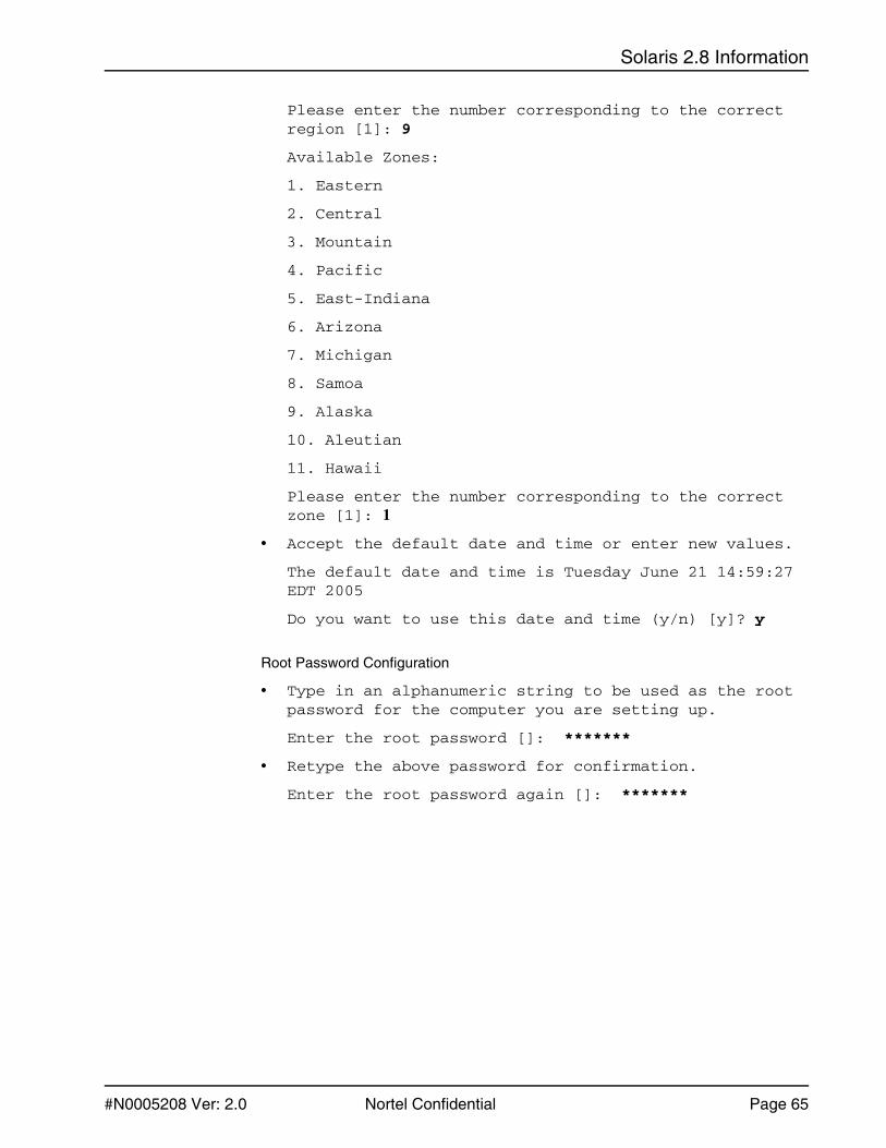
Solaris 2.8 Information
#N0005208 Ver: 2.0 Nortel Confidential Page 65
Please enter the number corresponding to the correct region [1]: 9
Available Zones:
1. Eastern
2. Central
3. Mountain
4. Pacific
5. East-Indiana
6. Arizona
7. Michigan
8. Samoa
9. Alaska
10. Aleutian
11. Hawaii
Please enter the number corresponding to the correct zone [1]: 1
• Accept the default date and time or enter new values.
The default date and time is Tuesday June 21 14:59:27 EDT 2005
Do you want to use this date and time (y/n) [y]? y
Root Password Configuration
• Type in an alphanumeric string to be used as the root password for the computer you are setting up.
Enter the root password []: *******
• Retype the above password for confirmation.
Enter the root password again []: *******

Media Processing Server Series PVI Components Reference Manual
Page 66 Nortel Confidential #N0005208 Ver: 2.0
• The following summary of responses to the previous prompts is displayed.
You have entered the following values:
Host Name: tb012
IP Address: 192.168.112.12
System part of a subnet: Yes
Netmask: 255.255.255.0
Primary Network Interface: bge0
Enable IPv6: No
Default Route: Autodetect Default Route
Name Service: None
Enable Kerberos: No
Time Zone: US/Eastern
Enter 'y' to apply these values and proceed to the next stage of the installation, or 'n' to return to the beginning and make changes (y/n): y
Please wait while the system is configured with your settings...
The route could not be detected at this time. If you wish to accept the settings provided, press ’Accept' and autodetection will be set for reboot, otherwise press 'Cancel' and provide another address.
1. Accept
2. Cancel
Enter the number corresponding to your choice [1] Return
Please wait while the system is configured with your settings...

Solaris 2.8 Information
#N0005208 Ver: 2.0 Nortel Confidential Page 67
• Install the Solaris software.
Solaris Web Start will assist you in installing software for Solaris.
<Press ENTER to continue> {"!" exits}
Installer Options
For many installations the following operations can be automatic. Manual operation may be appropriate if you plan to perform post-install system administration.
Reboot automatically after software installation [y]? Return
Eject a CD/DVD automatically after software installation [y]? Return
You have chosen the following Installer Options:
AutoReboot: y
AutoEject: y
Enter 'y' if this is correct, or 'n' to make changes [y] Return
Please specify the media from which you will install the Solaris Operating Environment.
Media:
1. CD/DVD
2. Network File System
3. HTTP (Flash archive only)
4. Local Tape (Flash archive only)
Media [1]: Return

Media Processing Server Series PVI Components Reference Manual
Page 68 Nortel Confidential #N0005208 Ver: 2.0
• Insert the first of two Solaris Software CDs.
Please insert the first Solaris Software disc from which you will install the Solaris Operating Environment.
To select a different media, enter B to go Back. []
Reading disc for Solaris Operating Environment...
The system is being initialized, please wait...
To install basic Solaris products into their default directory locations, select Default Install.
Custom install provides a choice of which Solaris products to install. For each product, it also provides an option to customize the products install.
Note: Default install is not possible. The filesystem requires manual layout.
! If the above message is displayed, the partition information is required. Use the partition table information that was printed when responding to the manual layout for partitioning. See Format and Partition the Disk, on page 54.
<Press ENTER to continue>
• Select the geographic regions and software localizations you want to install.
The English version of Solaris will be installed by default.
[ ] 0 Northern Africa
[ ] 1 Eastern Europe
[ ] 2 Southern Europe
[ ] 3 Central Europe
[ ] 4 Northern Europe
[ ] 5 Australasia
[-] 6 North America
[ ] 7 Western Europe
[ ] 8 Central America
[ ] 9 South America
[ ] 10 Middle East
[ ] 11 Asia

Solaris 2.8 Information
#N0005208 Ver: 2.0 Nortel Confidential Page 69
• Select which region(s) to install with the system. You will then be able to choose individual locales for each region.
To edit a region selection, enter the number here.
Enter n when finished. [n] Return
Available regions:
0 North America
1 POSIX
Default locale to be used: Return
English (United States,ISO8859-1) (en_US.ISO8859-1).
If you wish to change the locale to be used, enter the number next to the desired region to choose the locale to be used after the system has been installed or enter n to use the default. [n] Return
• Deselect the products to install at the following prompt.
Select the products you would like to install.
[ ] 0 Solaris 8 Documentation European167.1 MB
[ ] 1 Solaris 8 Documentation Asian0.0 MB
[ ] 2 Solaris 8 Software 2 of 20.0 MB
[ ] 3 Solaris 8 Software Supplement CD308.0 MB
Select which product(s) to install with the system. You will then be able to select individual product components.
• Additional Products
To scan for additional products, select the location you wish to scan. Products found at the selected location that are in a Web Start Ready install
form will be added to the Products list.
1. None
2. CD/DVD
3. Kiosk Download
4. Local or Network File System
Web Start Ready product scan location [1]: Return

Media Processing Server Series PVI Components Reference Manual
Page 70 Nortel Confidential #N0005208 Ver: 2.0
• Select to install the Developer Group (3). Other options can be installed but the Developer Group is required.
Available Solaris Software groups:
1. Entire Group Plus OEM (1048.9 MB)
2. Entire Group (1015.7 MB)
3. Developer Group (977.6 MB)
4. End User Group (629.0 MB)
5. Core Group (221.7 MB)
Select the number corresponding to the desired Solaris software group [2]: 3
• Install products and groups.
Please indicate if you want the Default Packages for the Entire Group or if you want to select Custom Packages. Selecting Custom Packages allows you to add or remove packages from the selected Solaris Software Group. When selecting which packages to add or remove, you will need to know about software dependencies and how Solaris software is packaged.
1. Default Packages
2. Custom Packages
Default Packages or Custom Packages [1] Return
• Select which disks you want to lay out the file systems on.
Required disk space: 2,354 MB
Available Disks:
Disk Size
c1t0d0 69994 MB
c1t1d0 69994 MB

Solaris 2.8 Information
#N0005208 Ver: 2.0 Nortel Confidential Page 71
• Enter 'y' to layout file systems on the specified disk. This will erase all existing data on the disk. Enter 'n' to leave the disk unmodified.
Layout file systems on disk c1t0d0 (bootdisk) (y/n) [y]? y
Layout file systems on disk c1t1d0 (y/n) [n]? n
• At least one of the disks selected for installing Solaris software has file systems or unnamed slices that you can choose to preserve. Do you want to preserve existing data?
Enter y to preserve data or n to skip data preservation. [n] Return
The Solaris Installer is determining size requirements based on your choices, please wait...
• The swap partition was not created on the first available cylinder. This is required for autolayout. Manual layout of the filesystems is required. This layout must be done on the cylinder level.
<Press ENTER to continue>
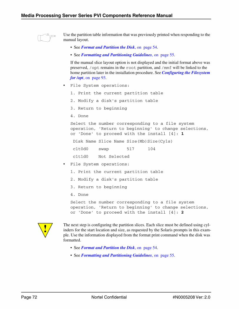
Media Processing Server Series PVI Components Reference Manual
Page 72 Nortel Confidential #N0005208 Ver: 2.0
Use the partition table information that was previously printed when responding to the manual layout.
• See Format and Partition the Disk, on page 54.
• See Formatting and Partitioning Guidelines, on page 55.
If the manual slice layout option is not displayed and the initial format above was preserved, /opt remains in the root partition, and /mmf will be linked to the home partition later in the installation procedure. See Configuring the Filesystem for /opt, on page 93.
• File System operations:
1. Print the current partition table
2. Modify a disk's partition table
3. Return to beginning
4. Done
Select the number corresponding to a file system operation, 'Return to beginning' to change selections, or 'Done' to proceed with the install [4]: 1
Disk Name Slice Name Size(Mb)Size(Cyls)
c1t0d0 swap 517 104
c1t1d0 Not Selected
• File System operations:
1. Print the current partition table
2. Modify a disk's partition table
3. Return to beginning
4. Done
Select the number corresponding to a file system operation, 'Return to beginning' to change selections, or 'Done' to proceed with the install [4]: 2
! The next step is configuring the partition slices. Each slice must be defined using cyl-inders for the start location and size, as requested by the Solaris prompts in this exam-ple. Use the information displayed from the format print command when the disk was formatted.
• See Format and Partition the Disk, on page 54.
• See Formatting and Partitioning Guidelines, on page 55.

Solaris 2.8 Information
#N0005208 Ver: 2.0 Nortel Confidential Page 73
• Place /opt and /mmf on separate slices.
• Assign slice 4 to /var.
• Assign slice 5 to /opt.
• Assign slice 6 to /usr.
• Assign slice 7 to /mmf.
• The following information is an example that explains the software disk 1 partitioning in terms of cylinders. It is an example, the actual installation may require different input values.
Partition Format Output=======================
SW DISK 1 Format Output=======================
Select a slice to modify, or Done to return to the previ-ous menu [8]: 0Enter new slice name: / Note: Do not enter root.Enter new start cylinder [0]: Note: Obtain the root cylinder start from the Partition Format Output.Enter new slice size (in Cyls) [8]: 4356 Note: The slice size is the block size.
PartTag FlagCylinders Size Blocks0 root wm 0 - 4355 6.00GB (4356/0/0) 125844841 swap wu 4356 - 5807 2.00GB (1452/0/0) 41948282 backup wu 0 - 24619 33.92GB (24620/0/0) 711271803 unassigned wm 5808 - 5823 22.57MB (16/0/0) 462244 unassigned wm 5824 - 6549 1.00GB (726/0/0) 20974145 unassigned wm 6550 - 10179 5.00GB (3630/0/0) 104870706 usr wm 10180 - 12357 3.00GB (2178/0/0) 62922427 unassigned wm 12358 - 24619 16.89GB (12262/0/0) 35424918
# Slice Name Start Cyl Size Cyl Minimum Size Cyl0 / 0 Cyl 4356 Cyls 0 Cyls1 swap 4356 Cyl 1452 Cyls 1452 Cyls3 unused4 unused5 unused6 unused7 unused

Media Processing Server Series PVI Components Reference Manual
Page 74 Nortel Confidential #N0005208 Ver: 2.0
Select a slice to modify, or Done to return to the previ-ous menu [8]: 3Enter new slice name: unassigned Enter new start cylinder [0]: 5808 Note: Obtain the unassigned cyl-inder start from the Partition Format Output. Enter new slice size (in Cyls) [8]: 16 Note: The slice size is the block size.
Select a slice to modify, or Done to return to the previ-ous menu [8]: 4Enter new slice name: varEnter new start cylinder [0]: 5824 Note: Obtain the var cylinder start from the Partition Format Output.Enter new slice size (in Cyls) [25]: 726 Note: The slice size is the block size.
# Slice Name Start Cyl Size Cyl Minimum Size Cyl0 /root 0 Cyl 4356 Cyls 0 Cyls1 swap 4356 Cyl 1452 Cyls 1452 Cyls3 /unassigned 5808 Cyl 16 Cyls 0 Cyls4 unused5 unused6 unused7 unused8 Done
# Slice Name Start Cyl Size Cyl Minimum Size Cyl0 /root 0 Cyl 4356 Cyls 0 Cyls1 swap 4356 Cyl 1452 Cyls 1452 Cyls3 /unassigned 5808 Cyl 16 Cyls 0 Cyls4 /var 5824 Cyl 726 Cyls 25 Cyls5 unused6 unused7 unused8 Done

Solaris 2.8 Information
#N0005208 Ver: 2.0 Nortel Confidential Page 75
Select a slice to modify, or Done to return to the previ-ous menu [8]: 5Enter new slice name: opt Enter new start cylinder [0]: 6550 Note: Obtain the opt cylinder start from the Partition Format Output.Enter new slice size (in Cyls) [300]: 3630 Note: The slice size is the block size.
Select a slice to modify, or Done to return to the previ-ous menu [8]: 6Enter new slice name: usr Enter new start cylinder [0]: 10180 Note: Obtain the usr cylinder start from the Partition Format Output.Enter new slice size (in Cyls) [882]: 2178 Note: The slice size is the block size.
# Slice Name Start Cyl Size Cyl Minimum Size Cyl0 /root 0 Cyl 4356 Cyls 0 Cyls1 swap 4356 Cyl 1452 Cyls 1452 Cyls3 /unassigned 5808 Cyl 16 Cyls 0 Cyls4 /var 5824 Cyl 726 Cyls 25 Cyls5 /opt 6550 Cyl 3630 Cyls 300 Cyls6 unused7 unused8 Done
# Slice Name Start Cyl Size Cyl Minimum Size Cyl0 /root 0 Cyl 4356 Cyls 0 Cyls1 swap 4356 Cyl 1452 Cyls 1452 Cyls3 /unassigned 5808 Cyl 16 Cyls 0 Cyls4 /var 5824 Cyl 726 Cyls 25 Cyls5 /opt 6550 Cyl 3630 Cyls 300 Cyls6 /usr 10180 Cyl 2178 Cyls 882 Cyls7 unused8 Done

Media Processing Server Series PVI Components Reference Manual
Page 76 Nortel Confidential #N0005208 Ver: 2.0
Select a slice to modify, or Done to return to the previous menu [8]: 7Enter new slice name: mmf Enter new start cylinder [0]: 12358 Note: Obtain the mmf cylinder start from the Partition Format Output.Enter new slice size (in Cyls) [8]: 12262 Note: The slice size is the block size.
Select a slice to modify, or Done to return to the previous menu [8]: 8
• Available disks:
1. c1t0d0
2. c1t1d0 Not Selected
3. Done
Select a disk to modify, or Done to return to the previous menu [3]: Return
• File System operations:
1. Print the current partition table
2. Modify a disk's partition table
3. Return to beginning
4. Done
Select the number corresponding to a file system operation, 'Return to beginning' to change selections, or 'Done' to proceed with the install [4]: Return
# Slice Name Start Cyl Size Cyl Minimum Size Cyl0 /root 0 Cyl 4356 Cyls 0 Cyls1 swap 4356 Cyl 1452 Cyls 1452 Cyls3 /unassigned 5808 Cyl 16 Cyls 0 Cyls4 /var 5824 Cyl 726 Cyls 25 Cyls5 /opt 6550 Cyl 3630 Cyls 300 Cyls6 /usr 10180 Cyl 2178 Cyls 882 Cyls7 /mmf 12358 12262 Cyls 08 Done

Solaris 2.8 Information
#N0005208 Ver: 2.0 Nortel Confidential Page 77
• A summary of the items that will be installed is displayed.
The following items will be installed:
Solaris Operating Environment:Solaris 8 Software HW 7/03Solaris Software Group: Entire GroupRegion and Locales:
North AmericaEnglish (United States) ( en_US )English (POSIX C) ( C )
System Locale: English (United States,ISO8859-1) ( en_US.ISO8
Enter 'y' to accept these values and start the installation, or 'n' to return to the beginning and make changes (y/n): y
Installing...
Installing Solaris software group|-1%----------25%-------------50%-------------75%-----------100%|
Pausing for 90 seconds at the "Summary" screen. The wizard will continue to the next step unless you select "Pause". Enter 'p' to pause. Enter 'c' to continue. [c]

Media Processing Server Series PVI Components Reference Manual
Page 78 Nortel Confidential #N0005208 Ver: 2.0
• Insert Disk 2 of the Solaris Software CD set.
Please specify the media from which you will install Solaris 8 Software 2 of 2 (HW 7/03 SPARC Platform Edition).
Installation details:
Product Result More Info1. Solaris 8 Collections - European Installed Available2. Done
Enter the number corresponding to the desired selection for more information, or enter 2 to continue [2]:
Preparing to Reboot...
SC Alert: Host System has ResetProbing system devicesProbing memoryProbing I/O buses
Sun Fire V240, No KeyboardCopyright 1998-2004 Sun Microsystems, Inc. All rights reserved.OpenBoot 4.16.2, 2048 MB memory installed, Serial #63035561.Ethernet address 0:3:ba:c1:d8:a9, Host ID: 83c1d8a9.
Initializing 1MB of memory at addr 103ff00000 - Initializing 1MB of memory at addr 103fde0000 - Initializing 14MB of memory at addr 103f002000 - Initializing 16MB of memory at addr 103e002000 - Initializing 992MB of memory at addr 1000000000 / - Initializing 1024MB of memory at addr 0 / - Rebooting with command: bootBoot device: /pci@1c,600000/scsi@2/disk@0,0:a File and args:
SunOS Release 5.8 Version Generic_108528-22 64-bitCopyright 1983-2003 Sun Microsystems, Inc. All rights reserved.
Hardware watchdog enabledconfiguring IPv4 interfaces: bge0.Hostname: tb012
The system is coming up. Please wait.checking ufs filesystems/dev/rdsk/c1t0d0s5: is clean./dev/rdsk/c1t0d0s7: is clean.Starting IPv4 routing daemon.starting rpc services: rpcbind done.Setting netmask of bge0 to 255.255.255.0Setting default IPv4 interface for multicast: add net 224.0/4: gateway tb012syslog service starting.Print services started.Jun 21 17:08:10 tb012 sendmail[223]: My unqualified host name (tb012) unknown; sleeping for retry volume management starting.

Solaris 2.8 Information
#N0005208 Ver: 2.0 Nortel Confidential Page 79
The system is ready. tb012 console login: rootPassword: *****Jun 21 17:08:19 tb012 login: ROOT LOGIN /dev/console Sun Microsystems Inc. SunOS 5.8 Generic Patch December 2002# df -kFilesystem kbytes used avail capacity Mounted on/dev/dsk/c1t0d0s0 1825087 52895 1717440 3% //dev/dsk/c1t0d0s6 2991343 823655 2107862 29% /usr/proc 0 0 0 0% /procfd 0 0 0 0% /dev/fdmnttab 0 0 0 0% /etc/mnttab/dev/dsk/c1t0d0s4 957783 10341 889976 2% /varswap 2212200 8 2212192 1% /var/runswap 2212208 16 2212192 1% /tmp/dev/dsk/c1t0d0s5 5011182 163523 4797548 4% /opt/dev/dsk/c1t0d0s7 4008942 9 3968844 1% /mmf# ls /optanswerbooks lost+found SUNWconn SUNWebnfs SUNWits SUNWrtvc#
The Solaris 2.8 installation is now complete. Proceed with the Solaris patch installation. See Step 2: Install Solaris Patches, on page 80.

Media Processing Server Series PVI Components Reference Manual
Page 80 Nortel Confidential #N0005208 Ver: 2.0
Step 2: Install Solaris Patches
Approximate installation time: 40 minutes.
The Solaris machine must be installed to a minimum of Solaris Patch Level Generic_117350-18.
! Nortel provides a CD with the Nortel approved Solaris 8 Patchbundles. Use this CD, supplied with the MPS 2.1 Solaris Media, CD number NTV800ABAB, to install the Solaris Patch software.
Enter the following command to display information about the Solaris software installed. The output contains the current patch level.
uname -a
For example, if the output is:
SunOS tb012 5.8 Generic_108528-22 sun4u sparc SUNW,Sun-Fire-V240
The output indicates the machine is installed up to Solaris Patch Level Generic_108528-22. This patch level does not meet the minimum requirements and the correct Solaris patch must be installed.
The Solaris Patch software is located on the Nortel Approved Solaris Patchbundles CD in the directory Patches_28.
To install this patch software:
• Change the directory to the Patches_28 directory.
cd Patches_28
• Enter the following at the command prompt.
./sunpatch28
• The patches in the patch directory are compared to the patches on the Solaris machine. These patches must be installed. Enter y at the prompt to install the patches.

Solaris 2.8 Information
#N0005208 Ver: 2.0 Nortel Confidential Page 81
The following is an example of the Solaris patch installation.
./sunpatch28solaris patch log will be: /var/sadm/solaris.patch061605140806check for errors in this file, and correct.
Checking for patches already installed, please wait.You will be prompted to continue after patchlist display...
The following patches are missing from this system.111111-04 110662-17 108987-15 108528-29 108869-29 109223-05 109805-17 109147-32 108949-08 108434-18 108435-18 111023-03 111317-05 113648-03 115827-01 116602-01 108993-40 109657-10 110723-07 108725-19 110943-04 110898-10 109324-07 110916-05 111098-02 109091-07 110387-05 110951-06 110903-07 109318-37 109320-13 109951-01 110945-08 111570-03 110286-12 111606-06 110668-05 108652-89 110670-02 108974-42 108977-04 108968-10 109896-29 108981-14 111874-07 111596-03 109667-07 108919-23 109885-16 109007-18 114251-01 112237-11 111879-01 112611-02 112668-02 111958-03 109154-21 109793-25 108806-18 110842-12 111321-04 112161-03 109134-31 109328-05 109326-16 111302-03 111308-05 110896-03 111883-30 113650-02 110934-20 114152-01 109354-24 109778-17 111792-11 112609-02 114984-01 110615-13 110335-03 109077-17 109202-06 109815-20 109887-18 110068-04 110416-04 117000-05 110820-12 110953-07 110955-05 111332-08 111400-03 111588-05 111624-05 111647-01 112390-09 117350-18 112792-01 113685-05 114045-12 114802-02 115797-01 116610-01 109460-10 112168-03 116455-01 111313-02 116959-07 116962-06 109613-07 114554-19 116973-01 111844-03 116965-08 113679-07 116986-02 116984-01 113749-02 108606-37 108773-19 108808-44 108921-23 108940-68 109023-04 109033-03 109896-29 109900-04 110208-19 110382-06 110953-07 110955-05 111304-02 111306-06 111588-05 111792-11 112438-03 113680-05 113681-03 118625-01 108712-01 108995-06 109025-05 109035-03 109165-14 109887-18 109889-07 110693-02 111400-02 111624-05 112174-01 112250-05 112279-02 116993-01 109931-10
Install patches now [y,n,?,q] y
The patch installation is now complete.

Media Processing Server Series PVI Components Reference Manual
Page 82 Nortel Confidential #N0005208 Ver: 2.0
Step 3: Reboot
To suppress sendmail messages, enter www. before nodomain.nocom in the /etc/hosts directory.
Reboot the system for all software changes to take effect.
After the Solaris 2.8 operating system (Step 1) and the Solaris patches (Step 2) are installed, the machine must be rebooted before proceeding to the next step.

Solaris 2.8 Information
#N0005208 Ver: 2.0 Nortel Confidential Page 83
Step 4: Set Network Lookup to Use Files
Set the network lookup to use files as follows.
• Create a copy of /etc/nsswitch.conf.
• edit /etc/nsswitch.conf to use files as the first or only choice.
If you are not using a naming service such as NIS or NIS+, use files only.
The following is a sample of nsswitch.conf using files only.
=========================================================# /etc/nsswitch.files:## An example file that could be copied over to # /etc/nsswitch.conf; it does not use any naming service.## "hosts:" and "services:" in this file are used only if# the /etc/netconfig file has a "-" for nametoaddr_libs of# "inet" transports.
passwd: filesgroup: fileshosts: filesnetworks: filesprotocols: filesrpc: filesethers: filesnetmasks: files bootparams: filespublickey: files
# At present there isn't a 'files' backend for netgroup; # the system will figure it out pretty quickly, and won't# use netgroups at all.
netgroup: filesautomount: filesaliases: filesservices: filessendmailvars: files=========================================================

Media Processing Server Series PVI Components Reference Manual
Page 84 Nortel Confidential #N0005208 Ver: 2.0
The following is a sample of nsswitch.conf using files and NIS.
=========================================================# /etc/nsswitch.nis:## An example file that could be copied over to # /etc/nsswitch.conf; it uses NIS (YP) in conjunction with# files.## "hosts:" and "services:" in this file are used only if# the /etc/netconfig file has a "-"for nametoaddr_libs of# "inet" transports.
passwd: files nisgroup: files nishosts: files nis [NOTFOUND=continue] dnsnetworks: files nis protocols: files nis rpc: files nis ethers: files nisnetmasks: files nis bootparams: files nispublickey: files nis netgroup: files nisautomount: files nisaliases: files nis
# for efficient getservbyname() avoid nis
services: files nissendmailvars: files =========================================================

Solaris 2.8 Information
#N0005208 Ver: 2.0 Nortel Confidential Page 85
Step 5: Run PVI Check
Download and run PVI Check to ensure the system meets the minimum requirements.
• For information on downloading PVI Check , see PVI Check on page 112.
• For information on PVI Check for Solaris, see PVI Check on the Solaris 2.8 Platform on page 117.
If files, such as PVI Check or Java, need to be transferred by ftp to the Solaris AP, /etc/ftpusers must be edited first. To transfer files by ftp, temporarily comment out the line root in /etc/ftpusers. Ensure that the comment is removed after files are transferred for security reasons.
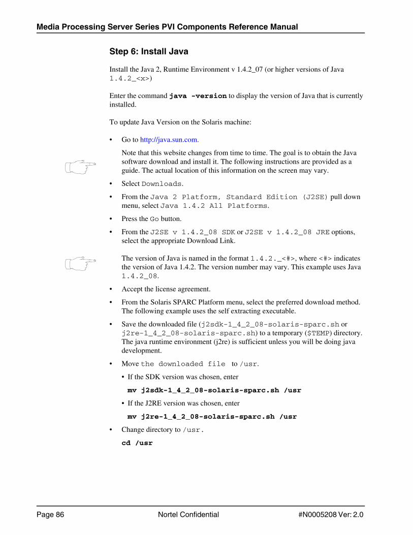
Media Processing Server Series PVI Components Reference Manual
Page 86 Nortel Confidential #N0005208 Ver: 2.0
Step 6: Install Java
Install the Java 2, Runtime Environment v 1.4.2_07 (or higher versions of Java 1.4.2_<x>)
Enter the command java -version to display the version of Java that is currently installed.
To update Java Version on the Solaris machine:
• Go to http://java.sun.com.
Note that this website changes from time to time. The goal is to obtain the Java software download and install it. The following instructions are provided as a guide. The actual location of this information on the screen may vary.
• Select Downloads.
• From the Java 2 Platform, Standard Edition (J2SE) pull down menu, select Java 1.4.2 All Platforms.
• Press the Go button.
• From the J2SE v 1.4.2_08 SDK or J2SE v 1.4.2_08 JRE options, select the appropriate Download Link.
The version of Java is named in the format 1.4.2._<#>, where <#> indicates the version of Java 1.4.2. The version number may vary. This example uses Java 1.4.2_08.
• Accept the license agreement.
• From the Solaris SPARC Platform menu, select the preferred download method. The following example uses the self extracting executable.
• Save the downloaded file (j2sdk-1_4_2_08-solaris-sparc.sh or j2re-1_4_2_08-solaris-sparc.sh) to a temporary ($TEMP) directory. The java runtime environment (j2re) is sufficient unless you will be doing java development.
• Move the downloaded file to /usr.
• If the SDK version was chosen, enter
mv j2sdk-1_4_2_08-solaris-sparc.sh /usr
• If the J2RE version was chosen, enter
mv j2re-1_4_2_08-solaris-sparc.sh /usr
• Change directory to /usr.
cd /usr

Solaris 2.8 Information
#N0005208 Ver: 2.0 Nortel Confidential Page 87
• Execute the following command.
• If the SDK version was chosen, enter
sh j2sdk-1_4_2_08-solaris-sparc.sh.
• If the J2RE version was chosen, enter
sh j2sdk-1_4_2_08-solaris-sparc.sh
If the shell script that was downloaded (j2sdk-1_4_2_08-solaris-sparc.sh or j2re-1_4_2_08-solaris-sparc.sh) is not an executable, enter the following command at the command line and execute the sh command to install Java.
• If the SDK version was chosen, enter
chmod 755 j2sdk-1_4_2_08-solaris-sparc.sh
• If the J2RE version was chosen, enter
chmod 755 j2re-1_4_2_08-solaris-sparc.sh
• Page through the documentation. Type yes to agree with the license terms.
• Enter the following command to remove the existing java directory (which is a link to /usr/java1.2).
rm /usr/java
• Enter the following command to link the new java directory.
• If the SDK version was chosen, enter
ln -s /usr/j2sdk1.4.2_08 /usr/java
• If the J2RE version was chosen, enter
ln -s /usr/j2re1.4.2_08 /usr/java
• Link the Java directory to /opt.
• If the SDK version was chosen, enter
ln -s /usr/j2sdk1.4.2_08 /opt/java
• If the J2RE version was chosen, enter
ln -s /usr/j2re1.4.2_08 /opt/java
If /opt does not exist, see Configuring the Filesystem for /opt on page 93.
• Verify the version of Java that is installed by entering the following command.
# java -version.
java version "1.4.2_08"

Media Processing Server Series PVI Components Reference Manual
Page 88 Nortel Confidential #N0005208 Ver: 2.0
Step 7: Install VNC
The software program Virtual Network Computing (VNC) provides a method of remote access between computers.
Install the latest version of Solaris VNC software on the Solaris machine.
To install VNC on a Solaris node:
• Open a browser window and enter following address to obtain the VNC software from the Real VNC web site.
http://www.realvnc.com/
• Select Download to obtain the Solaris software.
• Select and download the Compressed Tar file for Solaris (tar.Z) onto the Solaris node.
• Extract the contents of the compressed tar file.
• Copy the executable file vncviewer to the directory /usr/bin.

Solaris 2.8 Information
#N0005208 Ver: 2.0 Nortel Confidential Page 89
Step 8: Install Netscape Browser
Netscape Browser 7.0 or higher is required on the Solaris machine to open the documentation.
Download and install Netscape from the SUN website:
http://www.sun.com/software/solaris/browser/index.xml

Media Processing Server Series PVI Components Reference Manual
Page 90 Nortel Confidential #N0005208 Ver: 2.0
Step 9: Check Directories and Mount Points
Directories and mount points must be confirmed.
Special Considerations
The Nortel default MPS 500 product configuration consumes 720 MB in /opt, and 60 MB in the root filesystem for /tftpboot. The installation target and compo-nent location ($MPSHOME) can be changed from /opt to another filesystem, if nec-essary.
The /opt/bin directory must exist prior to installing Nortel software. Approxi-mately 11 kB will be consumed in /opt/bin. To create /opt/bin, see Configur-ing the Filesystem for /opt on page 93.
Multimedia files are typically installed in /mmf. However, they can be moved to a dedicated directory in any filesystem. The initial Nortel MPS product installation con-sumes approximately 10 MB in /mmf. Typically, several gigabytes of space are required for MMF data. This varies with the amount of audio files. More audio files requires more storage space. Space for mmf data should not be less than 4 GB. The partition /mmf can be a separate slice, disk, directory within the root filesystem, or link to another filesystem.
Before any changes are made, enter the command df -k to display the current file-system and space layout. The filesystem may differ from the following example
# df -k Filesystem kbytes used avail capacity Mounted on /dev/dsk/c1t0d0s0 1288279 909545 327203 74% / /proc 0 0 0 0% /proc fd 0 0 0 0% /dev/fd mnttab 0 0 0 0% /etc/mnttab swap 1911912 16 1911896 1% /var/run swap 1948184 36288 1911896 2% /tmp /dev/dsk/c1t0d0s7 68978746 9 68288950 1% /export.
In this example, the most space is available in /export.The /export filesystem will be used when configuring directories for space.
/opt and /mmf may have already been created in Step 1 when installing Solaris. Enter the df-k command to check if /opt and /mmf exist.
• If /opt and /mmf have not been created, continue to Configuring the Filesystem for /mmf on page 91 and Configuring the Filesystem for /opt on page 93.
• If /opt and /mmf have been created and meet the minimum requirements, go to Step 10: Turn on LOM (Lights Out Management) on page 95.

Solaris 2.8 Information
#N0005208 Ver: 2.0 Nortel Confidential Page 91
Configuring the Filesystem for /mmf
Create the mmf filesystem by performing one of the following three options (A, B or C). Login as user root to perform these scenarios. See Special Considerations, on page 90.
A: Mount a slice onto the File SystemMount a slice onto the file system. In the following example, slice 7 is mounted on /mmf.
1. Enter the following to create the /mmf directory within the root file-system.
mkdir /mmf
2. Create a backup copy of /etc/vfstab.
3. Add the following entry to /etc/vfstab.
/dev/dsk/c0t3d0s7 /dev/rdsk/c0t3d0s7 /mmf ufs 2 yes -
The above entry is an example. The controller number and disk number may be different from this example. For example, the entry c0t3d0 may be different for each installation. Use the information saved in Step 1 for the controller and disk number. See Formatting and Partitioning Guidelines, on page 55.
4. Enter the following to mount /mmf using the specifications in /etc/vfstab.
mount /mmf
If you receive any errors, /etc/vfstab must be corrected before continuing or rebooting.
5. Before rebooting, enter the command mountall to check the contents of the entire /etc/vfstab file for any errors that may have been generated when editing. Warnings about filesystems already mounted can be ignored. Any errors must be corrected before continuing or rebooting.
B: Use root FilesystemUse root filesystem if it adheres to the filesystem minimum size. The directory name is created in root. For example, the following command creates the directory /mmf in the root file system.
mkdir /mmf

Media Processing Server Series PVI Components Reference Manual
Page 92 Nortel Confidential #N0005208 Ver: 2.0
C: Link to Another FilesystemLink to another filesystem that supports the filesystem minimum size. In the following example, /mmf is linked to another filesystem:
1. Make a directory within the filesystem that supports the minimum size, where /export is mounted with a slice adhering to the minimum size.
mkdir /export/mmf
2. Link /mmf to /export/mmf. (/mmf should not exist before executing the above link command.)
ln -s /export/mmf /mmf
Ensure /mmf does not exist before executing the link command above.

Solaris 2.8 Information
#N0005208 Ver: 2.0 Nortel Confidential Page 93
Configuring the Filesystem for /opt
There are considerations for the /opt filesystem, if it exists in a filesystem smaller than required, and already contains product data.
Moving /opt would require uninstalling the products, and reinstalling the removed products into a different filesystem by specifying an install directory other than /opt. Moving or recreating /opt on a different file system can be difficult depending on the software already residing in it.
Either of the following two scenarios (A or B) can be used to increase space in /opt (without moving or recreating it) for the MPS installation. After step A or B is completed, go to step C.
A: Identify a Filesystem for /opt
Identify a filesystem which satisfies the minimum size requirements for /opt and use it instead of /opt, during the MPS install process.
1. Create a directory within the identified filesystem, for example:
mkdir /export/nortel
2. During the mps installation, specify the directory just created when prompted for the target installation directory and MPSHOME. For the above example, respond with the following.
/export/nortel
During the MPS software installation, this location is required. Use this location instead of the default location.
3. The Nortel software installation will create links within /opt/vps to the specified installation location. For the example above, the locations is /export/nortel.
4. Go to step C, see C: Create the /opt/bin Directory on page 94.

Media Processing Server Series PVI Components Reference Manual
Page 94 Nortel Confidential #N0005208 Ver: 2.0
B: Link /opt/vps to a Filesystem
Link /opt/vps to a filesystem that supports the minimum size requirements and accept the default options when prompted for locations during the MPS installation. See Step 15: Install Nortel Core and Patch Software, on page 102.
1. Create the /export/nortel directory.
mkdir /export/nortel
Where /export is a filesystem that supports minimum file size requirements for /opt.
2. Link the directories.
ln -s /export/nortel /opt/vps
3. Go to step C, see C: Create the /opt/bin Directory on page 94.
When installing Nortel Software, use the default values for MPSHOME and installation locations.
C: Create the /opt/bin Directory
The directory /opt/bin must exist before installing Nortel software. To create the directory, enter the following command.
mkdir –p /opt/bin

Solaris 2.8 Information
#N0005208 Ver: 2.0 Nortel Confidential Page 95
Step 10: Turn on LOM (Lights Out Management)
If the Power Management option Lights Out Manager (LOM) is an option, set auto power to on using the following commands.
cd /usr/platform/`uname -i`/sbin
./scadm set sc_powerstatememory true
./scadm set sc_powerondelay true

Media Processing Server Series PVI Components Reference Manual
Page 96 Nortel Confidential #N0005208 Ver: 2.0
Step 11: Disable Power Management
Use the following commands to disable Solaris Power Management.
/etc/init.d/power stop
cd /etc/rc2.d
If the letter s is capitalized in S85 power, enter the following command to change it to a lower case s.
mv S85power s85power

Solaris 2.8 Information
#N0005208 Ver: 2.0 Nortel Confidential Page 97
Step 12: Configure the ASE System Requirements
Configure the directory /etc/system for the ASE process.
Edit the file /etc/system and add the following entries to the end of the file if they do not already exist.
set shmsys:shminfo_shmmax=9437184
set shmsys:shminfo_shmseg=101
set semsys:seminfo_semmns=100
set semsys:seminfo_semmnu=50
set semsys:seminfo_semmsl=50

Media Processing Server Series PVI Components Reference Manual
Page 98 Nortel Confidential #N0005208 Ver: 2.0
Step 13: Create User peri Environment
In this step, create the /home directory for the user peri, create the user and group peri, and create a password for the user peri.
Step 13A: Create /home directory for User peri
Use the following instructions to create a home directory for the user peri.
• If /home is empty and does not meet the minimum filesystem requirements for /opt, perform Step 13A to create a user home directory in /opt or a filesystem compliant with space requirements of /opt and link to /home.
See Disk Partition Sizes, on page 54.
• If /home is not empty, skip Step 13A and perform Steps 13B and 13C.
Create a user home directory in /opt and link to /home (if /home is empty).
1. Enter the following command to open and edit the auto_master file.
vi /etc/auto_master
Comment out the line /home auto_home=nobrowse.
2. Enter the following command to unmount the /home directory.
umount /home
3. If /home exists in root, remove /home with the command.
rmdir /home
4. Create an /opt/home directory.
mkdir /opt/home
5. Link /opt/home to /home.
ln -s /opt/home /home
6. Enter the following command to create the directory /opt/home/peri.
mkdir -p /opt/home/peri
7. Continue to Step 13C: Create the User and Group peri on page 99

Solaris 2.8 Information
#N0005208 Ver: 2.0 Nortel Confidential Page 99
Step 13B: Link /home Directory for User peri
Link the /home directory for the user peri to /opt/home or a compliant filesystem.
If /home meets or exceeds the minimum filesystem requirements for /opt, skip Steps 13A and 13B. Perform Steps 13C and 13D.
1. Create a directory under /opt to be used as the /home directory for the user peri.
mkdir -p /opt/home/peri
2. Link /opt/home/peri to /home/peri.
ln -s /opt/home/peri /home/peri
Step 13C: Create the User and Group peri
Create the user and group peri as follows.
1. Create the group peri.
groupadd -g 20 peri
If a warning message is displayed, ignore the message and continue.
2. Create the user peri.
useradd -u 500 -d /home/peri -g peri -s /bin/csh peri
3. Check /etc/group for the following entry.
peri:20
4. Check /etc/passwd for the following entry.
peri:x:500:20:peri:/home/peri:/bin/csh
5. Set the owner of /home/peri to user peri with the following command.
chown –R peri /home/peri
6. Set the group of /home/peri to peri with the following command.
chgrp –R peri /home/peri

Media Processing Server Series PVI Components Reference Manual
Page 100 Nortel Confidential #N0005208 Ver: 2.0
Step 13D: Create a Password for peri
Create a password for the user peri as follows:
passwd peri
New password: *****
Re-enter password: *****
passwd: password successfully changed for peri

Solaris 2.8 Information
#N0005208 Ver: 2.0 Nortel Confidential Page 101
Step 14: Change the Reboot Scripts
The reboot scripts must be changed as follows.
• Remove existing scripts with the following commands.
mkdir /usr/sbin/orig
cd /usr/sbin
mv halt orig
mv reboot orig
rm -f /etc/reboot
• Create a reboot script by editing the file /usr/sbin/reboot and inserting:
init 6
• Create a halt script by editing the file /usr/sbin/halt and inserting:
init 0
• Reset the scripts with the following commands.
chmod 755 reboot halt
cd /etc
ln -s /usr/sbin/reboot reboot

Media Processing Server Series PVI Components Reference Manual
Page 102 Nortel Confidential #N0005208 Ver: 2.0
Step 15: Install Nortel Core and Patch Software
In this step, Nortel MPS core and patch software will be installed and the system will be configured for use.
• If Nortel software has never been installed on the Solaris machine, install Nortel core and patch software.
• See Install Nortel Core Software, on page 102.
• See Install Nortel Patch Software, on page 102.
• If Nortel software has previously been installed on the Solaris machine, applications and services must be terminated before installing Nortel core and patch software. See Terminating Applications and Services, on page 103.
Install Nortel Core Software
Approximate installation time: 20 minutes.
Install Nortel core software packages from the MPS Rel 2.1 Solaris Media and Documentation CD ROM, CD Number NTV800ABAB A0516614.
Refer to the section Automated Installation in Chapter 3 of the document Installing MPS Software on a Solaris Platform for information about installing Nortel core software on the Solaris platform.
During the PERIdoc package installation, there is a prompt to install Acrobat Reader. Adobe Acrobat Reader 5 or higher is required to display the MPS documentation.
Install Nortel Patch Software
Approximate installation time: 10 minutes.
Install the latest patchbundle and any prerelease patches from the Patchbundle CD named MPS Rel 2.1 Solaris Media and Documentation CD ROM (Patchbundle 9), CD Number NTV800ABAB A0516614.
The MPS Rel 2.1 Solaris Media and Documentation CD ROM (Patchbundle 9) may not contain the most current patches. Check the ESPL web site for the most recent patches. See PVI Check on page 112 for information on accessing the ESPL.
Refer to the README file on the CD for installation instructions.

Solaris 2.8 Information
#N0005208 Ver: 2.0 Nortel Confidential Page 103
Terminating Applications and Services
If Nortel software was previously installed on the Solaris node, use the following instructions to terminate applications and services before installing Nortel core and patch software.
The following applications and services must be terminated, as indicated below, before performing a fresh installation of Nortel software. To terminate applications and services enter the following commands.
• Login as root and stop the following services if they are running.
/etc/rc3.d/s20vps.startup
/etc/rc3.d/s30peri.plic
/etc/rc3.d/s95nortel.pdp
• If the scripts are running, use the following syntax to stop the services.
/etc/rc3.d/s20vps.startup stop
/etc/rc3.d/s30peri.plic stop
/etc/rc3.d/s95nortel.pdp stop
Once the above applications and services have been terminated, install Nortel core and patch software.
• See Install Nortel Core Software, on page 102.
• See Install Nortel Patch Software, on page 102.

Media Processing Server Series PVI Components Reference Manual
Page 104 Nortel Confidential #N0005208 Ver: 2.0
Step 16: Confirm Installation with perirev command
The perirev command displays information about all Nortel software installed on a node. It does not display information about software supplied by third party vendors.
The information displayed with the perirev command includes the names, dates and versions of the PERIpackages, resource-specific software integration packages, and patches distributed by Nortel installed on the node where the command is issued.
To display a list of Nortel software installed on a node, enter the following command.
/opt/vps/bin/perirev
perirev displays a list of all PERIpackages and patches installed on the node.

Solaris 2.8 Information
#N0005208 Ver: 2.0 Nortel Confidential Page 105
Step 17: Postinstallation Steps
To ensure that the installation and any associated procedure is correct, perform the postinstallation steps found in the section Postinstall Steps in Chapter 3 of the docu-ment Installing MPS Software on a Solaris Platform.

Media Processing Server Series PVI Components Reference Manual
Page 106 Nortel Confidential #N0005208 Ver: 2.0
Step 18: Configure the MPS
When configuring the MPS application processor, MPS, TMSCOMM component, and N+1 configuration issues must be addressed.
Refer to the section Configuring the MPS Application Processor in Chapter 3 of the document Installing MPS Software on a Solaris Platform for information about configuring the MPS application processor on a Solaris platform.
The automated installation procedure is recommended instead of the pkgadd procedure.

Solaris 2.8 Information
#N0005208 Ver: 2.0 Nortel Confidential Page 107
Step 19: Run SRP Status Report
Run the srp -status command to verify that all processes are in a RUNNING state.
To run this report, enter srp -status at the VSH prompt.

Media Processing Server Series PVI Components Reference Manual
Page 108 Nortel Confidential #N0005208 Ver: 2.0
Step 20: Perform Field Factory Test
Perform a Field Factory Test to confirm a successful PVI Installation was completed.
For more information, refer to Field Factory Test on page 134.

Solaris 2.8 Information
#N0005208 Ver: 2.0 Nortel Confidential Page 109
Security Hardening
Security hardening can be performed according to customer policies while adhering to the following considerations:
All unused services can be disabled. The following processes are not used by the MPS and can be commented in the Solaris 2.8 /etc/inetd.conf file:
! Do not disable the following processes, as they are required to boot the TMS and MPS processors.
• tftp
• bootpd
• CCLP
Ensure the following services remain enabled if using features that require them:
• uucp: required for remote Nortel Networks support
• rstatd: required for the open windows performance monitor, and statistics collection for PERIprpt reporting.
• daytime: required to synchronize the time on one machine with another.
• rsh, telnet, shell, login, ftp: required for remote access, unless they have been replaced by SSH.
amiserv ktkt_warnd rusersd
cachefsd name sadmind
chargen netstat sprayd
comsat ocfserv sunvts*
discard printer systat
dtspc rexd talk
echo rpc.cmsd time
finger rpc.metad ufsd
fs rpc.metamhd uucp
gssd rpc.ttdbserverd walld
kcms_server rquotad
*Nortel Field Engineer may turn this on for SUN diagnostic testing.

Media Processing Server Series PVI Components Reference Manual
Page 110 Nortel Confidential #N0005208 Ver: 2.0
OpenSSH can be obtained from http://www.openssh.org. Follow the OpenSSH build instructions. X applications, such as PeriView can be tunneled through SSH by adding the following to ssh_config and sshd_config:
XAuthLocation /usr/openwin/bin/xauth
ForwardX11 yes
And adding Add the following to sshd_config:
X11UseLocalhost no
For additional information regarding the installation of openSSH on Solaris, refer to http://www.sun.com/blueprints/0701/openSSH.pdf.
Disable start-up scripts for all unused daemons. The following /etc/rc2.d and /etc/rc3.d scripts are not used by the MPS and can be disabled by changing the first character of the script name to a lowercase letter:
! Do not disable start-up scripts that contain the following characters in the script name because they are required by Nortel processes.
nortel
peri
mps
vps
apache
If NFS server must be disabled, copy the portion that starts in.rarpd and rpc.bootparamd in /etc/rc3.d/S15nfs.server to a new /etc/rc3.d script, before renaming. The in.rarpd and rpc.bootparamd processes are required for MPS operation.
autofs lu snmp
autoinstall nscd spc
cachefs.daemon perf sysetup
cacheos.finish PRESERVE sysid.net
dmi power sysid.sys
ldap sendmail volmgt*
lp slpd xntpd
*can be disabled if the CD drive is not used

This chapter covers:
Testing
1. Testing and Validation
2. PVI Check
3. PVI Check on the Windows 2000 Platform
4. PVI Check on the Solaris 2.8 Platform

Media Processing Server Series PVI Components Reference Manual
Page 112 Nortel Confidential #N0005208 Ver: 2.0
Testing and Validation
This chapter describes using PVI Check to validate if hardware meets the minimum requirements for a customer-supplied server to support the MPS setup.
PVI Check
PVI Check is available for the MPS AP, Speech Server, and IPML. Downloaded PVI Check from the Enterprise Solutions PEP Library (ESPL), where MPS patchbundles and service packs are found. For the Windows platform, PVI Check is distributed as a zip file for stand-alone usage and contains all required binaries. To download PVI Check from the ESPL:
1. Register at http://www.nortel.com/register, the Nortelregistration site. Note any user ID or password that the site assigns.
2. Go to the Nortel web site - www.nortel.com/espl.
3. Click the Click Here button on this screen to get to the ESPL.
4. Scroll down to locate the Multimedia PEP Tools category.
5. Click the Click Here button next to Multimedia PEP Tools.
6. From the Product drop-down menu, select MPS, and then click on Search.
Figure 9: ESPL Main Screen
7. Select and download the PVI Check application for Windows 2000 or Solaris 2.8.

Testing
#N0005208 Ver: 2.0 Nortel Confidential Page 113
PVI Check on the Windows 2000 Platform
PVI Check compares the MPS Windows-based AP configuration file for threshold defaults and looks for the following requirements.
Minimum Required Hardware• Dual Xeon @ 2.8 GHz, 512 Kb L2 cache recommended• 1 GB RAM (DDR) minimum, 2 GB recommended• 12 GB hard disk• CD-ROM• Two 10/ 100/ 1000 Mbps Network Interface Cards• One Serial Port
Optional Hardware • Monitor• Keyboard • Mouse
PVI Check also looks for:
• Operating system version• Operating system service pack level• Host name of the network interface• pcAnywhere version 11.5• Hard drive partitions (see Recommended Disk Partitioning on page 45)
The recommended partitioning format is NTFS8K for better performance of audio file storage
• Hard drive formats — PVI Check recognizes different drive formats, such as the following:
• CD-ROM
• NTFS
• Ethernet address of the LAN interface for ordering license codes

Media Processing Server Series PVI Components Reference Manual
Page 114 Nortel Confidential #N0005208 Ver: 2.0
PVI Check Results
The following table shows the three possible status results of PVI Check for Windows.
For PVI Check to be a success, the Status column cannot have an Error. If there is an Error, appropriate action must be taken to resolve the issue before proceeding.
Table 10: PVI Check Status Results
Status Explanation
Okay Item passes and complies with the requirements.
Warning Item is not required but it is recommended.
Error Item fails and does not comply with the requirements.

Testing
#N0005208 Ver: 2.0 Nortel Confidential Page 115
PVI Check Execution
The utility can be run in the following forms:
• As a Graphical User Interface (GUI): To launch the GUI, invoke the command prompt and type pvicheck in the command line, or double-click the PVIcheck.exe icon. The resultant screen, which compares existing system settings to required default values, will look like the screen capture below.
To save the output as a log file, click the Save button at the upper right corner of the screen.
• As a command: Run the pvicheck -c command to activate PVI Check, which runs a system check for minimum hardware and other requirements. This is the console mode, and the default output is automatically saved as a log file in the following format:
C:\PviResults.log
Used for keycode retrieval/generation and licensing

Media Processing Server Series PVI Components Reference Manual
Page 116 Nortel Confidential #N0005208 Ver: 2.0
Figure 10: Sample PVI Results Output Log
The PVI Results output log may not display which version of pcAnywhere is installed because some versions of pcAnywhere do not set the expected registry key. If the ver-sion is incorrect, Error appears in the Status column.
Use the pvicheck -f <filename> command to give the output log file a name of your choice. The file is stored in the current destination directory.
Use the pvicheck -p command to specify which product. The MPS 1000 and MPS 500 are currently supported. The values are mps100 and mps500 (not case sensitive), with mps500 being the default option.

Testing
#N0005208 Ver: 2.0 Nortel Confidential Page 117
PVI Check on the Solaris 2.8 Platform
The utility checks if current Solaris hardware meets the requirements for an MPS system installation. The utility checks for the following items.
• System type
• Number of CPUs
• Disk space
PVI Check Execution
The following table shows the different invocations for PVI Check.
PVI Check Results
When PVI Check is executed, the output file is very large.The following table shows the three possible results of PVI Check for Solaris.
For successful PVI Check results, the items checked in every section cannot have FAIL as a result. The PVI Check results are summarized in the OVERALL SUM-MARY section where every option must be PASS to continue.
Table 11: PVI Check Invocations and Outputs
Invocation Explanation
$> pvicheck Generates output on stdout. This invocation is visible on screen and can be redirected.
$> pvicheck -f Saves the generated output to a default file PviResults.log in the current directory.
$> pvicheck -f <filename> Generates the output to the designated file in the current directory.
$> pvicheck xxxx Prints a brief help message.
Table 12: PVI Check Results
Result Explanation
PASS Item passes and complies with the requirements.
WARNING Item is not required but it is recommended.
FAIL Item fails and does not comply with the requirements.

Media Processing Server Series PVI Components Reference Manual
Page 118 Nortel Confidential #N0005208 Ver: 2.0
The following output is generated when PVI Check is run on a Sun-Blade 1500:
============================================================= ====================== SYSTEM DETAILS ====================================================================================
System: Sun-Blade-1500 OS VERSION: 5.8 Memory Size:1GB Speed:1062MHz NUM CPU:1 NUM DISK:1 NUM SERIAL:2 NUM USB:2 NUM DIMM:4 Hostname: wvets0jf Hostid: 832704fd Num Interfaces: 1 47.184.230.75 ================================================================================= DISK PARTITION CHECK=================================================================================
/Partition (10326052 KB) PASS /swap Partition (4930000 KB) WARNING SWAP partition should be on slice 1 /var Partition (10326052 KB) WARNING /var partition should be on slice 4 /opt Partition (10326052 KB) WARNING /opt partition should be on slice 5 /usr Partition (10326052 KB) WARNING /usr partition should be on slice 6 /mmf Partition (Not Found) FAIL ============================================================= ================ SYSTEM HARDWARE & OS CHECK=============================================================================
System Type Check(Sun-Blade-1500) FAIL Min CPU Check(1) FAIL 2 expected OS version Check(5.8) PASS Memory Size Check(1000000000) PASS 999999999 minimum Minimum Number of Network Interfaces Check(1) FAIL atleast 2 expected Minimum Number of Serial/USB Interface Check(2) PASS Check Total disk space (72811625) PASS Check Free disk space (67545362) PASS Check CDROM PASS Check PPP (2) PASS Check OS release (5.8 Generic_117000-01) PASS

Testing
#N0005208 Ver: 2.0 Nortel Confidential Page 119
============================================================= ===================== OVERALL SUMMARY ==================================================================================
Hardware Details: FAIL Software Details: PASS Disk & Partition Details: FAIL =============================================================

Media Processing Server Series PVI Components Reference Manual
Page 120 Nortel Confidential #N0005208 Ver: 2.0
This page has been intentionally left blank.

This chapter covers:
Service Description
1. Overview
2. Sample Service Description for IVR Systems

Media Processing Server Series PVI Components Reference Manual
Page 122 Nortel Confidential #N0005208 Ver: 2.0
Overview
The following sample Service Description for IVR Systems details support services offered by Nortel which includes proactive monitoring services for the MPS and PVI products. The sample Service Description details hours of available coverage, escala-tion processes, and the expected role of the customer for the services offered.
Sample Service Description for IVR Systems
The following Service Description for Nortel Support Services for IVR Systems is an example only. The most current version of the Service Description can be found on the Partner Information Center (PIC) web site. If you require this document and do not have access to PIC, please contact your sales person or Field Engineer. The PIC web site is http://navigate.us.nortel.com/imds?pg=/ptr/pic and the document is located on the MPS 500 product page, under Service and Technical Support.
SERVICE DESCRIPTIONNORTEL SUPPORT SERVICES FOR IVR SYSTEMS
This service description details Nortel’s support services for Interactive Voice Response (IVR) systems and related products and services, including licensed software and software applications. These include both "tradi-tional" support programs and new managed support services that include proactive monitoring and support of customers' IVR systems.
Traditional Support Programs
Managed Support Programs
!
Service Model GT5301000 Customer Care (Mon.-Fri., 9am-5pm local time)
Service Model GT5302000 Enhanced Customer Care (Mon.-Fri., 7am-7pm local time)
Service Model GT5303000 Premium Customer Care (7x24x365 service)
Service Model GT5320000 Managed Support (Mon.-Fri., 9am-5pm local time)
Service Model GT5321000 Enhanced Managed Support (Mon.-Fri., 7am-7pm local time)
Service Model GT5322000 Premium Managed Support (7x24x365 service)

Service Description
#N0005208 Ver: 2.0 Nortel Confidential Page 123
1. Service Program Choices: Traditional versus Managed IVR Support
1.1 Traditional Support Programs: Customer Contacts Nortel
Customers may request the services described in this Service Description by calling Nortel's Global Communi-cations Center at any time. Nortel's services will be delivered within the contractual hours of the applicable ser-vice program. The Global Communications Center serves as a single point of direction for our support organization worldwide, taking charge of problem determination, severity level assignment, dispatch/call rout-ing, alert notification, and call tracking/reporting. Pre-registered customers may also log technical support cases over a secure web site.
1.2 Managed Support Programs: Nortel Monitors and Responds to Customer Systems
Nortel's managed support services relieve customer representatives of many of the responsibilities typically associated with monitoring IVR systems and reporting error conditions. Systems that are placed under a man-aged support program will be monitored every fifteen (15) minutes during the contracted hours of coverage. Each 15-minute test will attempt to verify IVR system availability. In the event that an actual or potential error condition is detected, the report of such condition will be immediately passed to Nortel's technical support team for intervention during the contracted hours of coverage. By purchasing a managed support program, the customer will permit Nortel to initiate all corrective action necessary to evaluate and respond to the error con-dition. As part of this program, customers may arrange to have concurrent notification made to its own desig-nated personnel, and dynamically specify alert notification criteria (i.e. notify customer pager number xxx only if a problem of severity level yyy occurs during hours zzz).
2. Scope and Prerequisites of Managed Support Programs
2.1 Scope of Managed Support Programs
Because under managed support programs Nortel will often detect a system problem before it becomes appar-ent to a customer's own staff, such programs may improve the efficiency of IVR system operation at a given site. Although active monitoring and "automatic" response will tend to improve service responsiveness, the managed support programs will not detect all types of problems. Typically, the following conditions will be detected:
a) IVR System Availability• Ring-No-Answer• High & Dry• Special Information Tone (SIT)• Busy• Drop Calls
b) Network Routing• Wrong Destination• Missing Call Data
c) Overall IVR System Health and Functionality of Major Sub-Systems

Media Processing Server Series PVI Components Reference Manual
Page 124 Nortel Confidential #N0005208 Ver: 2.0
2.2 Technical Prerequisites for Managed Support Programs
The Customer must comply with the following requirements for all Managed Support programs:
a) For each system number and location (or port grouping), the customer shall establish toll-free dial-in access number and/or appropriate DNIS hunt group information;
b) Security arrangements necessary to permit remote access shall be implemented;
c) The customer's point of contact for concurrent alert notifications, and notification criteria, shall be clearly described;
d) Customers who develop their own IVR applications shall compile a link between the monitoring test application and the customer's IVR applications. If the Customer's application recompilation has errors that prevent the setup and operation of the Managed Support Program, Nortel may assess a charge to remedy the same on a time-and material basis. (If the customer's custom applications have been purchased from Nortel, this work will be performed by Nortel).
2.3 Initial Set-up of Managed IVR Support
For each site/enterprise where a customer has ordered a managed support service, Nortel and the Customer shall establish a technical coordination call to ensure that such site/enterprise is properly set up for the pro-gram. The placement of any order for a managed support service shall grant Nortel full authorization to proac-tively initiate technical response, including electronic and reasonable site access when necessary.
3. Service Level Objectives
All service programs incorporate certain service level objectives that are based upon the customer providing Nortel: (a) timely access to the systems and key personnel; and (b) efficient remote access to customer systems to analyze problems, run diagnostics, or review system configurations.
Sometimes the resolution of a problem may require customers to send additional information to our technical personnel. If the required information is not provided, the below service response times will be extended.
3.1 Definitions
a. "E1" - Problem or product defect causes complete loss of service and business cannot reasonably continue. The problem or defect has one or more of the following characteristics:
• System Outage
• System Hangs: system hangs indefinitely or there is severe performance degradation, causing unreasonable wait times for resources or response as if the system is hanging
• System Crashes Repeatedly: critical functionality is not available or the application cannot continue because a vital feature is not functioning.
b. "E2" - System or software functionality is limited to the degree that critical business processes are impacted or the problem is one that would prevent the site from going into production, and a work around solution does not readily exist.
c. "Major" - System or software functionality is limited to some degree however the loss of functionality has only minimal impact on the customer's operations, or a work-around solution exists which minimizes the operational impact of the problem.

Service Description
#N0005208 Ver: 2.0 Nortel Confidential Page 125
d. "Minor" - Minor anomalies in the system or software operation which have no discernible impact on the customer's operations, and/or routine customer requests concerning the operation or features of the system/software or its documentation.
3.2 Response Time Objectives (Remote Services)
a. E1 - Following receipt of telephone notice from a customer that an E1 condition exists, Nortel will commence corrective action, by telephone or remote electronic access, within thirty (30) minutes of the notice.
b. E2 - Following receipt of telephone notice from a customer that an E2 condition exists, Nortel will commence corrective action, by telephone or remote electronic access, within two hours of the notice.
c. Major - Following receipt of telephone notice from a customer that a Major condition exists, Nortel will commence corrective action within one business day.
d. Minor - Following receipt of telephone notice from a customer that a Minor condition exists, Nortel will commence corrective action within four (4) business days, or according to a mutually agreed schedule for routine software update services (see section 6.1(b)).
3.3 Response Time Objectives (On-Site Response)
Nortel will dispatch a field engineer to the customer site as soon as it is determined that a problem requires hardware-related support, or other field assistance. The dispatch will be made within each support program's specified hours of coverage. The average time to arrive at a customer's site location will be highly dependent upon the city location. Customers may obtain Nortel's average response times (measured from the time of Nortel's dispatch of a field engineer) for a given city on an order-specific basis.
4. Escalation of Unresolved Technical Support Cases
Nortel has internal escalation procedures (Attachment A) which guide and structure technical responses to all unresolved customer calls and cases. Nortel's support personnel are required to escalate all unresolved cases to our technical support management teams, and onward to successively higher levels of technical and opera-tional management, until the case is resolved
5. Support Services
5.1 Preventative Services
Each year, Nortel will schedule a date on which a field engineer will come to a customer's site during normal business hours to conduct certain preventative maintenance activities. The site visit will normally include a review of whether any software maintenance releases, updates, or patches are required, and subsequent coordi-nation to deliver these services to the customer. If applicable, hardware "change orders" that improve operat-ing reliability may be implemented, with customer concurrence. Typically, a brief meeting with the customer's site representative will be part of this annual event.

Media Processing Server Series PVI Components Reference Manual
Page 126 Nortel Confidential #N0005208 Ver: 2.0
5.2 Corrective Intervention
Nortel's Global Communications Center enables customers to request the correction of malfunctions in sys-tems and related hardware and software (including application software) delivered by Nortel. With a single call or web-logged entry, customers can initiate the intervention of our support team. For any given technical sup-port case, Nortel provides the customer an assigned case identification number, which is internally tracked as we deploy internal resources to deliver prompt call resolution. All services are delivered within the hours spec-ified for each support program. Most calls for corrective action and technical support are resolved by tele-phone and/or remote diagnostic access to the customer's system. If Nortel determines that the malfunction or outage in question is a potential hardware failure, we will dispatch one of our field engineers to the customer site. Each service program includes all labor, travel, and parts expended in Nortel's delivery of services.
5.3 Application Developers Support Center
The Application Developers Support Center supports routine customer inquiries about the usage, operating procedures, or documentation of our systems, software releases, or application development tools. The Appli-cation Developers Support Center is available to customer personnel who have completed a Nortel profes-sional certification program in application development. Assistance is provided during the hours of 09:00 to 5:00pm, Monday to Friday, Eastern Standard Time.
6. Software and Information Services
6.1 Service Releases, Patches, and Updates
Nortel IVR support programs include certain system maintenance service releases, software patches and soft-ware updates. All such software products are licensed in accordance with the Purchase/License Agreement that the customer has previously entered into with Nortel (or for major distributors, the applicable Distributor Agreement), and are subject to the following terms:
a) Maintenance-related software releases, patches, and updates that are critical to resolving a system malfunction or outage (i.e. E1 or E2 condition) will be delivered during the days/hours of the applicable support program.
b) All other maintenance-related software releases, patches, and updates will be delivered to end user customers and major Nortel distributors during Nortel's normal working hours. All such software services shall have a "Minor" case classification and be pre-scheduled in writing with the customer or distributor. The software releases, patches, and updates described in this section are not available to resellers.
c) Nortel IVR support programs do not include any new, functionally enhancing software releases that Nortel may bring to market according to separate license fees.
6.2 Information Services
Nortel provides pre-registered customers access to select IVR-related technical documents on a secure website.

Service Description
#N0005208 Ver: 2.0 Nortel Confidential Page 127
6.3 Speech Recognition License Upgrades (Applicable to Customers with Speech License Coverage)
For customers who have placed a specific number of speech recognition licenses under continuous support program coverage, Nortel will install upgrades to such licenses according to the following criteria:
a) Upgrades will be made for the same number of covered licenses (typically "per port" licenses), and at the same speech recognition tier level that is applicable for the covered licenses;
b) The upgrade will be the license version which has been formally integrated, tested, and commercially released by Nortel for authorized use in connection with Nortel's systems. In no event will any other license versions be installed or supported by Nortel, even if they are made commercially available by the speech licensing supplier (i.e. Nuance, SpeechWorks, etc.) under its own terms of distribution.
c) All upgrades must be formally scheduled in advance and confirmed in writing by Nortel, based upon an approximate lead time of 30-60 days.
d) Separate license fees will apply to any increase in port licenses, or addition/expansion of license tier levels, additional languages, or new or expanded features, all of which are outside the scope of this Service Description.
e) Separate technical support fees will generally apply to grammar or application updating, recompilation, testing, and system deployment. Specific situations will require a separate quotation from Nortel based on numerous variables. Similarly, "throughput performance tuning" and/or accuracy tuning may be separately chargeable according to Nortel's prevailing labor rates and lead times, depending on the nature of the license upgrades, application parameters, and other variables.
7. Customer Obligations
7.1 Cooperation and Site Preparations
Nortel's delivery of all services herein requires that the customer provide full cooperation with Nortel's support personnel, including local and remote system access (subject to customer's reasonable security controls), work-ing space, temporary storage of parts, electrical current, and satisfactory working conditions at the applicable customer site.
7.2 System Back-ups
Back-up copies of data on system memory disks will be essential to aid Nortel in restoring a system to opera-tion after a system outage or other malfunction. Customers are expected to make frequent, scheduled "back-ups" to all data recorded in system memory devices.
8. Special Rule for Support of MPS Systems Under the "Platform Vendor Independent" Program
8.1 A customer may purchase the support services for MPS-500 and MPS-1000 model IVR systems that par-tially consist of Qualified Third Party Components (defined below). This approach will enable the customer to enjoy the full, "seamless" benefit of all of the services described in this Service Description, without the diffi-culties that are posed by contracting with multiple third party OEM vendors. (Typically OEM vendors' terms of support are far more restrictive than the scope of Nortel's service programs as detailed herein). The follow-ing conditions will apply to the purchase of a customer care plan or managed support plan when Qualified Third Party Components are involved:

Media Processing Server Series PVI Components Reference Manual
Page 128 Nortel Confidential #N0005208 Ver: 2.0
a) "Qualified Third Party Components" means the customer-furnished hardware devices and software components detailed in Nortel's Publications N0005208 and N0017042 (current releases) and such additional sourcing specifications or instructions that may be furnished or published by Nortel.
b) When the customer desires to use Qualified Third Party Components in its MPS-500 or MPS-1000 system configuration, the customer shall fully comply with the operational and administrative requirements of the aforementioned publications, including the purchase of the applicable installation services from Nortel.
c) Following the installation of the MPS-500/MPS-1000 system(s) Nortel will supply the customer certain identification numbers which physically mark the installed system(s) and Qualified Third Party Components. Nortel will offer support services only for such system(s) and Qualified Third Party Components.
8.2 Nortel's support of systems configured under the Platform Vendor Independent program shall be strictly limited to the services described in this Service Description. The customer's election of the PVI program and/or procurement of specific Qualified Third Party Components shall be at its sole risk and expense. The customer shall retain full responsibility for the lead times, costs, and operational risks of evaluating, procuring, manag-ing, storing, using, integrating, and disposing of Qualified Third Party Components.
8.3 The customer shall retain full responsibility for:
i) purchasing, storing, and making available without charge to Nortel, on-site spares for the Qualified Third Party Components. This responsibility shall include ensuring that the spares inventory is adequate to permit tolerable recovery time frames.
ii) Regulatory and safety evaluation and practices regarding the Qualified Third Party Components and the engineering of their usage, such as Ethernet cabling, power consumption, power distribution, power cabling, heat dissipation, floor loading, etc.
General Terms and Conditions for all IVR Support Services
1. Days and Hours of Coverage - Service days and hours of coverage exclude Nortel holidays, except in the case of 24x7 programs (Premium Customer Care and Premium Managed Support) where services are delivered 365 days/year.
2. Purchase Orders - A customer purchase order is required to purchase support services. The purchase order must have a term of at least one year, and incorporate the terms of this Service Description and any "master" purchase/license agreements in force between the parties.
3. Pricing and Fee Assumptions - All pricing must conform to a valid quotation issued by Nortel and is subject to Nortel's review and acceptance. All fees quoted for support programs are based upon Nortel obtaining prompt payment for invoices issued under purchase orders for services. Fees for all support programs covered by this Service Description are further subject to Nortel retaining title to any parts which are removed from systems in the conduct of maintenance actions.
4. Payment - Payment of the quoted annual fees for all support plans, plus applicable taxes, shall be due and payable quarterly in advance upon receipt of a Nortel invoice. Invoice terms shall be net 30 days.
Service Description
#N0005208 Ver: 2.0 Nortel Confidential Page 129
5. Add-on Adjustments - If a customer purchases or licenses additional equipment or software which is installed in a product that is covered by a support plan, the plan fees shall be increased by the applicable addi-tional amount. All Nortel products at a site must be covered by the same support plan.
6. Inspection/Re-Certification - If a customer desires to purchase a support plan for Nortel products that have had their respective warranty period (or their purchased annual support program coverage) lapse, Nortel will quote the fees for inspecting and/or re-certifying such products. Re-certification fees may include, at Nortel's discretion, retroactive payment of monthly fees for the applicable support plan, multiplied by the number of months that the products have been uncovered by such support plan. Following customer's placement of a purchase order for the quoted fees, the system in question will become eligible for a support plan once all nec-essary inspection/recertification activities are complete.
7. System Moves, Adds, and Changes - System relocations, add-on modifications, and/or other modifications are not covered by the aforementioned support plans but may be separately quoted by Nortel upon request.
8. After-Hours Services - If a Customer desires remedial services outside the contracted hours, Nortel will require a separate purchase order or written request, authorizing all such "after hours" services to be performed on an hourly billable basis at Nortel's prevailing hourly rates, plus travel expense (if applicable). Nortel cannot assure the availability of such "after hours" services, which will always be subject to resource availability.
9. Prohibited Customer Actions - Nortel support plans require that the customer neither perform, nor allow any third party to perform, any repair actions or other physical/electronic maintenance of systems covered by a Nortel support plan. Should Nortel deliver services which result from these prohibited activities, all such ser-vices shall be separately billable at Nortel' prevailing labor and material rates. Similarly, corrective mainte-nance occasioned by the negligence of the customer, its employees or representatives, faulty electric current, faulty air conditioning, system relocation (other than by Nortel), or by the use of devices or special attachments not provided or authorized in writing by Nortel, or by any other abnormal use will be separately billable at Nortel's prevailing labor and material rates.

Media Processing Server Series PVI Components Reference Manual
Page 130 Nortel Confidential #N0005208 Ver: 2.0
ATTACHMENT A TO SERVICE DESCRIPTION:INTERNAL ESCALATION PROCEDURE FOR IVR TECHNICAL SUPPORT CASES
T = Time at which Nortel initiates corrective action following a customer call to the Global Communications Center. (All times intervals refer to periods within the hourly schedule specified in the purchased support pro-gram).
E1 Cases
E2 Cases
Major Cases
Minor Cases: Not Applicable
Alert Notification Groups
T2hr Global Communication Center notifies Alert Group 1
T4hr Global Communication Center notifies Alert Groups 1 & 2
T6hr Global Communication Center notifies Alert Groups 1, 2 & 3(if applicable, notifications every business day until resolution)
T8hr Global Communication Center notifies Alert Groups 1, 2 & 3(if applicable, notifications every business day until resolution)
T4hr Global Communication Center notifies Alert Group 1
T8hr Global Communication Center notifies Alert Groups 1 & 2
T16hr Global Communication Center notifies Alert Groups 1, 2 & 3(if applicable, notifications every business day until resolution)
T24hr Global Communication Center notifies Alert Groups 1, 2 & 3(if applicable, notifications every business day until resolution)
T8hr Global Communication Center notifies Alert Group 1
TOnce Weekly Global Communication Center notifies Alert Groups 1 & 2(if applicable, notifications every week until resolution)
Group 1
Regional Field Service ManagerTechnical Support Management TeamManager, Global Communications CenterTechnical Support Manager, EMEA*Technical Support Manager, Asia*
Group 2
Sr. Director, IVR Enterprise Technical SupportService Director, Multimedia Applications
Group 3
Leader, Enterprise Customer Service Operations
Installation RoadMaps

Media Processing Server Series PVI Components Reference Manual
Page 132 Nortel Confidential # N0005208 Ver: 2.0
PVI Installation Road Maps Overview
Road maps provide a framework to guide you through the installation of products in a PVI environment. The installation road maps are specific to the products installed in a PVI environment. Use the following directory to locate the road map for the product-specific PVI installation you intend to perform. For information on any software requirements, see Software Requirements and System Configuration on page 40.
Product-Specific PVI Road Map Go To
PVI Road Map #1: MPS Software on a Windows Platform page 136
PVI Road Map #2: MPS Software on a Solaris Platform page 138
PVI Road Map #3: Speech Server Installation page 140
PVI Road Map #4: CDD Installation page 143
PVI Road Map #5: PAF Installation page 146
PVI Road Map #6: Installing PAF on a WVADS Workstation page 148

Maps
# N0005208 Ver: 2.0 Nortel Confidential Page 133
Prerequisites for a PVI Installation
The following checklist identifies prerequisites for a PVI Installation.
Preinstallation Checklist
Ensure the following prerequisites are met and know what the goal of the PVI installation is.
• Ensure that PVI Check was run at the installation location, and you have received and reviewed a copy of the PVI Check log before scheduling the test.
• Obtain the Customer Specification Sheet.
• Obtain and be familiar with the Network Overview Diagram and Configuration Statistics into which the PVI system will be integrated.
• Know the node name, IP address, and component numbers for all systems on which software is being installed.
• Obtain necessary software for the PVI installation.
• Obtain necessary documentation in a usable format.
• Obtain necessary licenses.
• Obtain the appropriate network privileges.
• Ensure proficiency with operating systems (UNIX, Windows) and PVI installation procedures.
• Ensure you have access to an authorized customer contact person who can provide information and make decisions if consultation is necessary.
• Refer to the individual road maps for a summary of installation procedures.
Rerun PVI Check
Ensure that PVI Check is run again before beginning the installation. Continue the installation only when the PVI Check results are satisfactory.
For more information on running PVI Check, see PVI Check on page 112.

Media Processing Server Series PVI Components Reference Manual
Page 134 Nortel Confidential # N0005208 Ver: 2.0
Field Factory Test
A Field Factory Test (FFT) can be performed using the test routines built into the PERIfft package to ensure the PVI installation was successful and the MPS platform is functional. The PERIfft package contains procedures and documentation to complete the FFT. PERIfft is included in Patchbundle 9. Newer patch levels of PERIfft must be patched in when they are available. There is a patch level for Windows 2000 and a patch level for Solaris 2.8. The following sections identify what is contained in the PERIfft package for Windows and Solaris.
Windows 2000 PERIfft Package
The Windows 2000 PERIfft patch level must be at 3.3 or later. In addition, Microsoft Services for UNIX 3.5 must be downloaded and select portions of the package must be installed on the MPS AP. Specific details on Microsoft Services for UNIX can be found in MPS500/100 Win2000 FFT Procedure (0136679) (see below for location of this document). Do not install the entire package.
After installing the Windows 2000 PERIfft package, the procedure for the Field Factory Test is in PDF format and is located in the following directory:
%mpshome%/PERIfft/fftests/docs
The following table indicates which test procedure document to use to execute a specific FFT.
Document Number FFT Documentation Items Tested
0136679 MPS500/100 Win2000 FFT Procedure
TMS assembly, Chassis and Backplane (excludes TPM hardware)
0136682 MPS500 Win2000 TPM FFT Procedure
TPM-200/800/1100 and CTPM hardware
0136681 OSCAR 6 FFT Procedure Speech Server configuration and functionality

Maps
# N0005208 Ver: 2.0 Nortel Confidential Page 135
Solaris 2.8 PERIfft Package
The Solaris 2.8 PERIfft patch level must be level 3.2 or later. After installing the Solaris 2.8 PERIfft package, the procedure for the Field Factory Test is in PDF format and is located in the following directory:
/opt/vps/PERIfft/fftests/docs
The following table indicates which test procedure document to use to execute a specific FFT.
Document Number FFT Documentation Items Tested
0136672 MPS500 FFT Procedure TMS assembly, Chassis and Backplane (excludes TPM hardware)
0136678 MPS500 TPM - FFT Procedure
TPM-200/800/1100 and CTPM hardware
0136681 OSCAR 6 FFT Procedure Speech Server configuration and functionality

Media Processing Server Series PVI Components Reference Manual
Page 136 Nortel Confidential # N0005208 Ver: 2.0
PVI Road Map #1: MPS Software on a Windows Platform
Use this road map to install MPS software in a PVI environment for Windows 2000. The software can be installed on an MPS 500 Application Server or PeriView Workstation.
For complete information about installing the MPS software on the Solaris platform, refer to Installing MPS Software on the Windows Platform.
Step Installing MPS Software on the Windows Platform (Sheet 1 of 2)
1 Comply with the prerequisites:• Preinstallation Checklist on page 133.• Rerun PVI Check on page 133.
2 Display READ_1st file• Use Windows Explorer to locate the file on the MPS Rel 2.1 Windows
2000 Media and Documentation CD ROM (Patchbundle 9), CD Number NTV801AAAB A0516615.
• Read the instructions in the file, and keep it open for the rest of the installation.
3 Before installing Nortel software:• Install XVision 7 if using a PeriView Workstation.• Define the peri user ID.
For more information, refer to the section Installation Prerequisites in Installing MPS Software on the Windows Platform.
4 Install Nortel core software packages from the MPS Rel 2.1 Windows 2000 Media and Documentation CD ROM (Patchbundle 9), CD Number NTV801AAAB A0516615.
Choose Typical installation, unless you require optional add-on packages. You can also choose the Custom procedure to install packages individually.
At the beginning of the installation, you are prompted to select the type of node on which you are installing software. Your response to this prompt determines what software is actually installed.
• Select MPS if installing on an MPS Application Server node.• Select Workstation if installing on a PeriView Workstation node.
For more information, refer to the section Preparing to Install MPS Software in Installing MPS Software on the Windows Platform
5 If you are installing PERIvxml:• Install PERIvxml.• Add Speech Server components in the vpshosts file. Restart the MPS
AP or PeriView Workstation.
For more information, refer to the section VoiceXML Installation and Configuration in VoiceXML User’s Guide.

Maps
# N0005208 Ver: 2.0 Nortel Confidential Page 137
6 Install the latest patchbundle and any prerelease patches. The patchbundle can be found on the MPS Rel 2.1 Windows 2000 Media and Documentation CD ROM (Patchbundle 9), CD Number NTV801AAAB A0516615.
• Click the patch folder, then click the PERImps2xPatchbundle executable to install the patchbundle.
• Install any prerelease patch executables individually.
7 Reboot the computer before starting the Nortel applications.
Nortel applications need valid licenses to run. Verify that licenses are installed and available after the installation process is complete. Configure and comply with the licensing requirements.
For more information, refer to the section Working with the License Server in Installing MPS Software on the Windows Platform.
8 Confirm the packages have been installed using the perirev command.
For more information, refer to the section Confirm that Packages have been Installed in Installing MPS Software on the Windows Platform.
9 Perform postinstallation steps:
• If you installed XVision, set up TCP/IP transport.• If you installed Exceed, configure NutCRACKER.• Edit the bootptab file.• If you installed PeriStudio, back up and restore sample files.• If you installed PeriRDB, verify installation of libraries before usage.• Work with the license file:
• Obtain the keycode.• Edit the license file.• Start or stop the license server.
• Synchronize system time.• Configure the telephony protocol using the PeriView.• View a summary of all MPSs on a system or a node.• Manage MMF resources.
For information on how channel partners can obtain licenses, refer to Distributor Technical Reference Bulletin No. DTR-2004-0252-GLOBAL, How to request MPS 500 and IPML/ CTI 2.1 KRS license files for customer-supplied server solutions and PVI solutions.
10 Reboot the system.
11 Perform a Field Factory Test to confirm a successful PVI Installation was completed.
For more information, refer to Field Factory Test on page 134.
Step Installing MPS Software on the Windows Platform (Sheet 2 of 2)

Media Processing Server Series PVI Components Reference Manual
Page 138 Nortel Confidential # N0005208 Ver: 2.0
PVI Road Map #2: MPS Software on a Solaris Platform
Use this road map to install MPS software in a PVI environment for Solaris 2.8. The software can be installed on an MPS 500 or MPS 1000 Application Processor or PeriView Workstation.
• For complete information about installing the MPS software on the Solaris platform, refer to Installing MPS Software on the Solaris Platform.
• Before you begin, comply with the prerequisites:
• Preinstallation Checklist on page 133.
• Rerun PVI Check on page 133.
The following steps in this road map corresponds to the section Installation Overview in Chapter 4 of this document. See Installation Overview on page 50..
Step Procedure (Sheet 1 of 2)
1 Install Solaris 2.8Approximate installation time: 1.5 hours.
2 Install Solaris PatchesApproximate installation time: 40 minutes.
3 Reboot
4 Set Network Lookup for Use Files
5 Run PVI Check
6 Install Java
7 Install VNC
8 Install Netscape Browser
9 Create Directories and Mount Points
10 Turn on LOM (Lights Out Management), if applicable.
11 Disable Power Management
12 Configure the ASE System Requirements
13 Create User peri Environment
• Create /home directory for user peri• Link /home directory for user peri• Create the user and group peri• Create a password for peri
14 Change the Reboot Scripts

Maps
# N0005208 Ver: 2.0 Nortel Confidential Page 139
15 Install Nortel Core and Patch Software
• Install Nortel Core SoftwareApproximate installation time: 20 minutes.
• Install Nortel Patch SoftwareApproximate installation time: 10 minutes.
• Terminating Applications and Services
16 Confirm Installation with perirev Command
17 Postinstallation Steps
18 Configure the MPS
19 Run SRP Status Report
20 Perform the Field Factory Test
Step Procedure (Sheet 2 of 2)
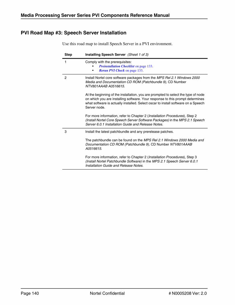
Media Processing Server Series PVI Components Reference Manual
Page 140 Nortel Confidential # N0005208 Ver: 2.0
PVI Road Map #3: Speech Server Installation
Use this road map to install Speech Server in a PVI environment.
Step Installing Speech Server (Sheet 1 of 3)
1 Comply with the prerequisites:• Preinstallation Checklist on page 133.• Rerun PVI Check on page 133.
2 Install Nortel core software packages from the MPS Rel 2.1 Windows 2000 Media and Documentation CD ROM (Patchbundle 9), CD Number NTV801AAAB A0516615.
At the beginning of the installation, you are prompted to select the type of node on which you are installing software. Your response to this prompt determines what software is actually installed. Select oscar to install software on a Speech Server node.
For more information, refer to Chapter 2 (Installation Procedures), Step 2 (Install Nortel Core Speech Server Software Packages) in the MPS 2.1 Speech Server 6.0.1 Installation Guide and Release Notes.
3 Install the latest patchbundle and any prerelease patches.
The patchbundle can be found on the MPS Rel 2.1 Windows 2000 Media and Documentation CD ROM (Patchbundle 9), CD Number NTV801AAAB A0516615.
For more information, refer to Chapter 2 (Installation Procedures), Step 3 (Install Nortel Patchbundle Software) in the MPS 2.1 Speech Server 6.0.1 Installation Guide and Release Notes.

Maps
# N0005208 Ver: 2.0 Nortel Confidential Page 141
4 Install a Speech Server resource. This software is distributed by the speech resource vendor. Use the following information to install any Speech Server resource supported by PVI in the MPS 2.1 environment. For complete information about installing a Speech Server resource, refer to the MPS 2.1 Speech Server 6.0.1 Installation Guide and Release Notes. For information that is generic to all Speech Server resources, refer to the MPS Speech Server 6.0.1 Reference Guide. This document applies to all speech resources, regardless of the speech resource vendor. For information that is specific to a particular Speech Server resource, refer to the vendor-specific resource guides named in the format MPS Speech Server 6.0.1 <Resource Name> Resource Guide. For example, for information about OSR 2.0.x, refer to the MPS Speech Server 6.0.1 SpeechWorks OXR 2.0.x Resource Guide.
4a Install a Speech Server resource using the software distributed by the resource vendor.
To install the vendor software, refer to Chapter 2 (Installation Procedures), Step 4 (Install Vendor Resource Software) in the MPS 2.1 Speech Server 6.0.1 Installation Guide and Release Notes.
Ensure that you read and comply with the following sections in Chapter 2 (Installation Procedures) in the MPS 2.1 Speech Server 6.0.1 Installation Guide and Release Notes:
• Step 1 - Comply with Prerequisites• Step 2 - Install Nortel Core Speech Server Software Packages• Step 3 - Install Nortel Patchbundle Software
The required operations addressed in these sections have been completed in steps 1-3 of the Speech Server Installation road map. However, the MPS 2.1 Speech Server 6.0.1 Installation Guide and Release Notes focuses on speech issues and sections 1-3 provide additional background information.
4b Install Nortel vendor-specific Software Integration Package.
The software can be found on the MPS Rel 2.1 Windows 2000 Media and Documentation CD ROM (Patchbundle 9), CD Number NTV801AAAB A0516615.
To install the vendor-specific Software Integration Package, refer to Chapter 2 (Installation Procedures), Step 5 (Install Nortel Resource Integration Software) in the MPS 2.1 Speech Server 6.0.1 Installation Guide and Release Notes.
4c Configure Files.
Speech Server installations require some configuration after installation.
For more information about configuring files, refer to Chapter 2 (Installation Procedures), Step 6 (Configure Files) in the MPS 2.1 Speech Server 6.0.1 Installation Guide and Release Notes.
Step Installing Speech Server (Sheet 2 of 3)

Media Processing Server Series PVI Components Reference Manual
Page 142 Nortel Confidential # N0005208 Ver: 2.0
4d Configure Licensing.
Licensing is a resource-specific issue and you must comply with the licensing requirements.
For more information on licensing, refer to Chapter 2 (Installation Procedures), Step 7 (Licensing) in the MPS 2.1 Speech Server 6.0.1 Installation Guide and Release Notes.
5 Restart the nodes on which software was installed.
Speech Server processing can begin only after installation, configuration, and licensing requirements are met and the node is restarted.
For more information, refer to Chapter 2 (Installation Procedures), Step 8 (Restart the Speech Server Node) in the MPS 2.1 Speech Server 6.0.1 Installation Guide and Release Notes.
Step Installing Speech Server (Sheet 3 of 3)

Maps
# N0005208 Ver: 2.0 Nortel Confidential Page 143
PVI Road Map #4: CDD Installation
A CDD installation requires that CDD be installed on an MPS Application Server and a Web Server. CDD installation on a PeriView Workstation is optional.
Before beginning the installation on any machine, the MPS Application Server, Speech Servers, and PeriView Workstation (if applicable) must be installed, configured, and in a Running state according to SRP.
Step CDD Installation (Sheet 1 of 3)
1 Comply with the prerequisites:• Preinstallation Checklist on page 133.• Rerun PVI Check on page 133.
2 Comply with CDD-specific prerequisites.
The following systems must be installed with software up to Patchbundle 9, configured and in a Running state according to SRP.
MPS Application Server• refer to PVI Road Map #1: MPS Software on a Windows Platform on page 136.• refer to PVI Road Map #2: MPS Software on a Solaris Platform on page 138.
Speech Server• refer to PVI Road Map #3: Speech Server Installation on page 140.
PeriView Workstation (if applicable)• refer to PVI Road Map #1: MPS Software on a Windows Platform on page 136.• refer to PVI Road Map #2: MPS Software on a Solaris Platform on page 138.
Ensure that the VXML grammar is deployed from the VXML package on the MPS server to the Speech Server.
Use the VXML sample application to verify if the ASR/TTS/AUSVR Speech Servers are functional on the respective transport dial-ins.
3 Install CDD.
Perform the required steps, Step 3a and 3b. Perform Step 3c only if you are installing CDD on an PeriView Workstation.
• Step 3a: Install CDD on an MPS Application Server (required).• Step 3b: Install CDD on a Web Server (required).• Step 3c: Install CDD on an PeriView Workstation (optional).

Media Processing Server Series PVI Components Reference Manual
Page 144 Nortel Confidential # N0005208 Ver: 2.0
3a Install CDD on an MPS Application Server (required).
The MPS must be installed with software up to Patchbundle 9, configured and in a Running state according to SRP before beginning this installation. See PVI Road Map #1: MPS Software on a Windows Platform on page 136.
• Install PAF.Refer to the WCSS Portable Application Framework 1.0 Installation Guide.
• Install CDD.Refer to the Corporate Directory Dialer Installation Guide.
• Execute the perirev command to verify that PERIpaf and PERIcorpd are installed.
• Assign lines to applications on the MPS based on call control method.
Depending on the call control method (see below), select the correct application to assign to lines on the MPS.
• VoiceXML• CCXML• PERIProducer
For more information, refer to the Corporate Directory Dialer User’s Guide.
3b Install CDD on a Web Server (required).
• Third-party software must exist on the Web Server before installing PAF software.
• J2SDK 1.4.1• JBOSS 3.0.7 or WebSphere• JBOSS service tool from utilities CD to add JBOSS as a service
Obtain the Web Server software from the following sources:• J2SDK — utilities CD• JBOSS — www.jboss.org or utilities CD• WebSphere — IBM
• Install PAF.Refer to the WCSS Portable Application Framework 1.0 Installation Guide.
• Install CDD.Refer to the Corporate Directory Dialer Installation Guide.
• Execute the perirev command to verify that PERIpaf and PERIcorpd are installed.
• Start the Web Server.
• Configure the Corporate Directory Dialer on the Web Server. Refer to the Corporate Directory Dialer User’s Guide.
• To test Corporate Directory Dialer, see step 5.
Step CDD Installation (Sheet 2 of 3)

Maps
# N0005208 Ver: 2.0 Nortel Confidential Page 145
3c Install CDD on an PeriView Workstation (optional).
The PeriView Workstation must be installed with software up to Patchbundle 9, configured and in a Running state according to SRP before beginning this installation.
• Install PAF.Refer to the WCSS Portable Application Framework 1.0 Installation Guide.
• Install CDD.Refer to the Corporate Directory Dialer Installation Guide.
• Execute the perirev command to verify that PERIpaf and PERIcorpd are installed.
• Run the srp -status command to verify that the StatsClient is in a Running state.
4 Restart the nodes on which software was installed.
5 To test the Corporate Directory Dialer on the JBOSS Web Server:
• Create a temporary LDAP for testing the Corporate Directory Dialer.
• Copy the OpenLDAP folder and follow the README instructions to set up the test directory and carry out the testing procedure.
The README file resides on the J2SDK utilities CD in the path: \openLDAP\README.html.
Step CDD Installation (Sheet 3 of 3)

Media Processing Server Series PVI Components Reference Manual
Page 146 Nortel Confidential # N0005208 Ver: 2.0
PVI Road Map #5: PAF Installation
A PAF installation requires that PAF be installed on an MPS Application Server and a Web Server. PAF installation on a PeriView Workstation is optional.
• If you are installing CDD, use the CDD Installation road map instead of the PAF Installation road map. See PVI Road Map #4: CDD Installation on page 143.
• If you are installing PAF on a WVADS Workstation, see PVI Road Map #6: Installing PAF on a WVADS Workstation on page 148.
Before beginning the installation on any system, the MPS Application Server, Speech Servers, and PeriView Workstation (if applicable) must be installed, configured, and in a Running state according to SRP.
Step PAF Installation (Sheet 1 of 2)
1 Comply with the prerequisites:• Preinstallation Checklist on page 133.• Rerun PVI Check on page 133.
2 Install PAF.
Perform the required steps, Step 2a and 2b. Perform Step 2c only if you are installing PAF on a PeriView Workstation.
• Step 2a: Install PAF on an MPS Application Server (required).• Step 2b: Install PAF on a Web Server (required).• Step 2c: Install PAF on a PeriView Workstation (optional).
2a Install PAF on an MPS Application Server (required).
The MPS must be installed with software up to Patchbundle 9, configured and in a Running state according to SRP before beginning this installation. See PVI Road Map #1: MPS Software on a Windows Platform on page 136.
• Install PAF.Refer to the WCSS Portable Application Framework 1.0 Installation Guide.
• Execute the perirev command to verify that PERIpaf is installed.

Maps
# N0005208 Ver: 2.0 Nortel Confidential Page 147
2b Install PAF on a Web Server (required).
• Third-party software must exist on the Web Server before installing PAF software.
• J2SDK 1.4.1• JBOSS 3.0.7 or WebSphere• JBOSS service tool from the utilities CD to add JBOSS as a service
Obtain the Web Server software from the following sources:• J2SDK — utilities CD• JBOSS — www.jboss.org or utilities CD• WebSphere — IBM
• Install PAF.Obtain the PAF software from the MPS Packaged Applications CD.Refer to the WCSS Portable Application Framework 1.0 Installation Guide.
• Execute the perirev command to verify that PERIpaf is installed.
• Start the Web Server.
• Configure the Web Server.Refer to the Corporate Directory Dialer User’s Guide.
2c Install PAF on a PeriView Workstation (optional).
The PeriView Workstation must be installed with software up to Patchbundle 9, configured and in a Running state according to SRP before beginning this installation.
• Install PAF.Refer to the WCSS Portable Application Framework 1.0 Installation Guide.
• Execute the perirev command to verify that PERIpaf is installed.
• Run the srp -status command to verify that the StatsClient is in a Running state.
3 Restart the nodes on which the software was installed.
Step PAF Installation (Sheet 2 of 2)

Media Processing Server Series PVI Components Reference Manual
Page 148 Nortel Confidential # N0005208 Ver: 2.0
PVI Road Map #6: Installing PAF on a WVADS Workstation
Use this road map to install PAF on a WVADS Workstation.
If you are installing PAF on an MPS Application Server, Web Server, or PeriView Workstation, see PVI Road Map #5: PAF Installation on page 146.
Before beginning the installation, the WVADS Workstation must be installed, configured, and in a Running state according to SRP.
Step Installing PAF on a WVADS Workstation
1 Comply with the prerequisites:• Preinstallation Checklist on page 133.• Rerun PVI Check on page 133.
2 Install and Configure the WVADS Workstation.
Refer to the WCSS Application Development Tool Guide.
3 Install PAF on the WVADS Workstation.
• Install PAF.Refer to the WCSS Portable Application Framework 1.0 Installation Guide.
• Execute the perirev command to verify that PERIpaf is installed.
4 Restart the nodes on which software was installed.

Index

Media Processing Server Series PVI Components Reference Manual
Page 150 Nortel Confidential #N0005208 Ver: 2.0
AAdobe Acrobat Reader 43, 49
Application Processor 21CTI 21Windows 2000 Server 21Windows Specifications 21
ASE system requirements 97
Ccall processing 14
EEthernet Switch 20
BPS 2000 20
FField Factory Test 134
Ggroup peri 98
HHardware Cabling 30
Hardware Requirements 14AP 14VPN 14
Iinstall
CDD 143MPS Software for Solaris 2.8 138MPS Software for Windows 2000 136Nortel patches 102, 137, 140Nortel software 102, 136, 140PAF 146PAF on WVADS 148prerequisites 133
Pre-Install Check List 133Rerun PVI Check 133
Solaris 2.8 52Speech Server 140
JJava 49, 86
LLOM 95
LSOF 49
MMedia Processing Server 8
Modem 30Belkin Model # F5U021 30Multitech #MT5634ZBA-USB 30Multitech MT5634-ZDX 30
MPS 1000 14Solaris 2.8 platform 14
MPS 500 14TMS 14VoIP 14
NNetscape browser 89
Network Topology Diagrams 18
nsswitch.conf 83, 84NIS 84
OOpenSSH 110
Operating System Patches 45
PPerformance Statement 16
PERIdist 44
PERIfft 134
PERIinstaller 44
PeriProducer 14
PERIsnmp 44
Power Management 96
prerequisites 133
Rreboot scripts 101
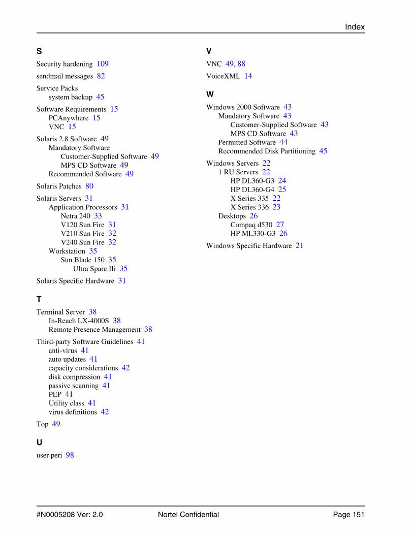
Index
#N0005208 Ver: 2.0 Nortel Confidential Page 151
SSecurity hardening 109
sendmail messages 82
Service Packssystem backup 45
Software Requirements 15PCAnywhere 15VNC 15
Solaris 2.8 Software 49Mandatory Software
Customer-Supplied Software 49MPS CD Software 49
Recommended Software 49
Solaris Patches 80
Solaris Servers 31Application Processors 31
Netra 240 33V120 Sun Fire 31V210 Sun Fire 32V240 Sun Fire 32
Workstation 35Sun Blade 150 35
Ultra Sparc IIi 35
Solaris Specific Hardware 31
TTerminal Server 38
In-Reach LX-4000S 38Remote Presence Management 38
Third-party Software Guidelines 41anti-virus 41auto updates 41capacity considerations 42disk compression 41passive scanning 41PEP 41Utility class 41virus definitions 42
Top 49
Uuser peri 98
VVNC 49, 88
VoiceXML 14
WWindows 2000 Software 43
Mandatory Software 43Customer-Supplied Software 43MPS CD Software 43
Permitted Software 44Recommended Disk Partitioning 45
Windows Servers 221 RU Servers 22
HP DL360-G3 24HP DL360-G4 25X Series 335 22X Series 336 23
Desktops 26Compaq d530 27HP ML330-G3 26
Windows Specific Hardware 21