Embed Size (px)
Citation preview
1
MEDIA RELEASE
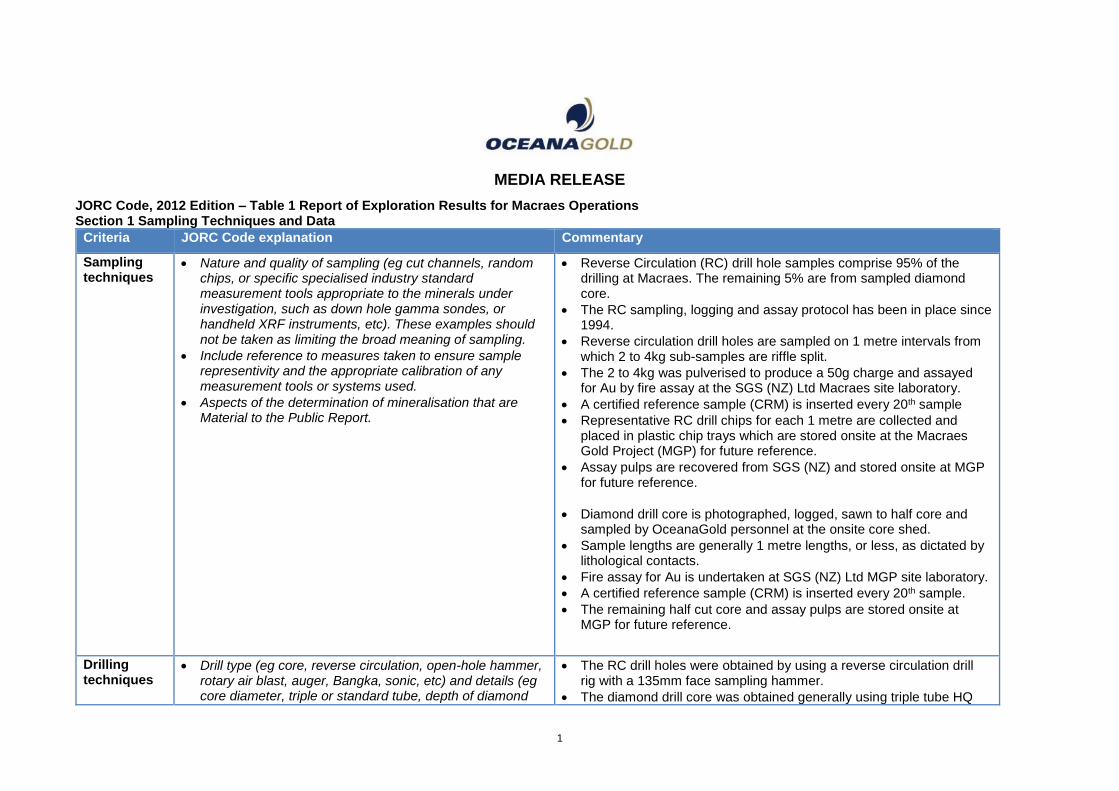
JORC Code, 2012 Edition – Table 1 Report of Exploration Results for Macraes Operations Section 1 Sampling Techniques and Data
Criteria JORC Code explanation Commentary
Sampling techniques
• Nature and quality of sampling (eg cut channels, random chips, or specific specialised industry standard measurement tools appropriate to the minerals under investigation, such as down hole gamma sondes, or handheld XRF instruments, etc). These examples should not be taken as limiting the broad meaning of sampling.
• Include reference to measures taken to ensure sample representivity and the appropriate calibration of any measurement tools or systems used.
• Aspects of the determination of mineralisation that are Material to the Public Report.
• Reverse Circulation (RC) drill hole samples comprise 95% of the drilling at Macraes. The remaining 5% are from sampled diamond core.
• The RC sampling, logging and assay protocol has been in place since 1994.
• Reverse circulation drill holes are sampled on 1 metre intervals from which 2 to 4kg sub-samples are riffle split.
• The 2 to 4kg was pulverised to produce a 50g charge and assayed for Au by fire assay at the SGS (NZ) Ltd Macraes site laboratory.
• A certified reference sample (CRM) is inserted every 20th sample
• Representative RC drill chips for each 1 metre are collected and placed in plastic chip trays which are stored onsite at the Macraes Gold Project (MGP) for future reference.
• Assay pulps are recovered from SGS (NZ) and stored onsite at MGP for future reference.
• Diamond drill core is photographed, logged, sawn to half core and sampled by OceanaGold personnel at the onsite core shed.
• Sample lengths are generally 1 metre lengths, or less, as dictated by lithological contacts.
• Fire assay for Au is undertaken at SGS (NZ) Ltd MGP site laboratory.
• A certified reference sample (CRM) is inserted every 20th sample.
• The remaining half cut core and assay pulps are stored onsite at MGP for future reference.
Drilling techniques
• Drill type (eg core, reverse circulation, open-hole hammer, rotary air blast, auger, Bangka, sonic, etc) and details (eg core diameter, triple or standard tube, depth of diamond
• The RC drill holes were obtained by using a reverse circulation drill rig with a 135mm face sampling hammer.
• The diamond drill core was obtained generally using triple tube HQ
2
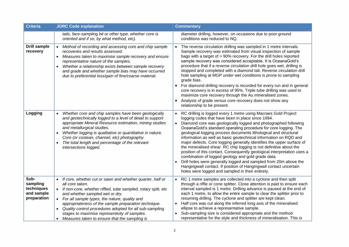
Criteria JORC Code explanation Commentary
tails, face-sampling bit or other type, whether core is oriented and if so, by what method, etc).
diameter drilling, however, on occasions due to poor ground conditions was reduced to NQ.
Drill sample recovery
• Method of recording and assessing core and chip sample recoveries and results assessed.
• Measures taken to maximise sample recovery and ensure representative nature of the samples.
• Whether a relationship exists between sample recovery and grade and whether sample bias may have occurred due to preferential loss/gain of fine/coarse material.
• The reverse circulation drilling was sampled in 1 metre intervals. Sample recovery was estimated from visual inspection of sample bags with a target of > 90% recovery. For the drill holes reported sample recovery was considered acceptable. It is OceanaGold’s procedure that if a reverse circulation drill hole goes wet, drilling is stopped and completed with a diamond tail. Reverse circulation drill hole sampling at MGP under wet conditions is prone to sampling grade bias.
• For diamond drilling recovery is recorded for every run and in general core recovery is in excess of 95%. Triple tube drilling was used to maximize core recovery through the Au mineralised zones.
• Analysis of grade versus core recovery does not show any relationship to be present.
Logging • Whether core and chip samples have been geologically and geotechnically logged to a level of detail to support appropriate Mineral Resource estimation, mining studies and metallurgical studies.
• Whether logging is qualitative or quantitative in nature. Core (or costean, channel, etc) photography.
• The total length and percentage of the relevant intersections logged.
• RC drilling is logged every 1 metre using Macraes Gold Project logging codes that have been in place since 1994.
• Diamond core was geologically logged and photographed following OceanaGold’s standard operating procedure for core logging. The geological logging process documents lithological and structural information as well as basic geotechnical information on RQD and major defects. Core logging generally identifies the upper surface of the mineralised shear. RC chip logging is not definitive about the position of this contact. Consequently geological interpretation uses a combination of logged geology and gold grade data.
• Drill holes were generally logged and sampled from 20m above the Hangingwall contact. If position of Hangingwall contact uncertain holes were logged and sampled in their entirety.
Sub-sampling techniques and sample preparation
• If core, whether cut or sawn and whether quarter, half or all core taken.
• If non-core, whether riffled, tube sampled, rotary split, etc and whether sampled wet or dry.
• For all sample types, the nature, quality and appropriateness of the sample preparation technique.
• Quality control procedures adopted for all sub-sampling stages to maximise representivity of samples.
• Measures taken to ensure that the sampling is
• RC 1 metre samples are collected into a cyclone and then split through a riffle or cone splitter. Close attention is paid to ensure each interval sampled is 1 metre. Drilling advance is paused at the end of each 1 metre, to allow the entire sample to clear the splitter prior to resuming drilling. The cyclone and splitter are kept clean.
• Half core was cut along the inferred long axis of the mineralised ellipse to achieve a representative sample.
• Sub-sampling size is considered appropriate and the method representative for the style and thickness of mineralisation. This is

3
Criteria JORC Code explanation Commentary
representative of the in situ material collected, including for instance results for field duplicate/second-half sampling.
• Whether sample sizes are appropriate to the grain size of the material being sampled.
borne out by 26 years of mining at Macraes.
• Where sufficient core is available, generally >15kgs and preferably >30kgs of quarter cut core, metallurgical samples are selected. Due to the volume requirement this means a metallurgical sample may consist of material from multiple holes.
• Metallurgical sampling aims to be as geologically and spatially representative as possible.
• RC chips cannot be used at MGP for metallurgical sampling due to contamination with hammer oil which negatively impacts sulphide float test work.
Quality of assay data and laboratory tests
• The nature, quality and appropriateness of the assaying and laboratory procedures used and whether the technique is considered partial or total.
• For geophysical tools, spectrometres, handheld XRF instruments, etc, the parametres used in determining the analysis including instrument make and model, reading times, calibrations factors applied and their derivation, etc.
• Nature of quality control procedures adopted (eg standards, blanks, duplicates, external laboratory checks) and whether acceptable levels of accuracy (ie lack of bias) and precision have been established.
• At MGP, SGS (NZ) Ltd operates an assay laboratory under contract to OceanaGold (NZ) Ltd.
• QAQC procedures involve the use of certified reference material, lab duplicates, and lab standards. Sample batches are re-assayed if 1 of the OceanaGold CRM’s is outside defined limits.
Sample preparation RC 1. Samples checked off against submission sheet. 2. Samples are then dried at 150 degrees until visibly dry. 3. Entire sample is crushed. Crush size is under 5mm and approximately 500g is retained for pulverising. 4. The 500 gram sample is pulverised to 90% passing 75 micron.
Sample preparation diamond
1. Samples checked off against submission sheet. 2. Samples are then dried at 150 degrees until visibly dry. 3. Entire core pre-crushed using a crusher. Nominal top size is 30mm (in one dimension only). 3. Entire sample is crushed. Crush size is under 5mm and approximately 500g is retained for pulverising. 4. The 500 gram sample is pulverised to 90% passing 75 micron.
Assay 50g fires assays were completed using SGS’s FAA505 scheme.
1. 50 gram of sample is weighed with 170 gram of lead flux and tumble mixed in a plastic pot.

4
Criteria JORC Code explanation Commentary
2. contents are transferred to a crucible and fusion of the gold in the sample with the lead in the flux occurs in a LPG fired blast furnace at 1,100 degrees C. 4. cupellation of the lead button to recover the gold prill then occurs in an LPG fired muffle furnace set at 950 degrees C. 5. the prills are recovered from the cupels, digested in plastic test tubes with aqua regia. Gold determinations by atomic absorption. Q/QC is checked and results released.
Verification of sampling and assaying
• The verification of significant intersections by either independent or alternative company personnel.
• The use of twinned holes.
• Documentation of primary data, data entry procedures, data verification, data storage (physical and electronic) protocols.
• Discuss any adjustment to assay data.
• Geological logging is compiled digitally using Tough Books at the drill site or the core shed.
• At hole completion the digital log is loaded into the MGP acQuire exploration database and validated.
• Geological observation of mineralisation is generally well correlated with assay results.
• No adjustments are made to the assay data received from SGS (NZ) Ltd.
Location of data points
• Accuracy and quality of surveys used to locate drill holes (collar and down-hole surveys), trenches, mine workings and other locations used in Mineral Resource estimation.
• Specification of the grid system used.
• Quality and adequacy of topographic control.
• All drill hole collars are surveyed by OceanaGold mine surveyors using MGP grid to an accuracy of +/- 0.10 metre
• All drill holes are down hole surveyed every 30m using a digital down hole camera.
• Topographic control is by detailed aerial surveys of mine and prospect areas to 0.5m accuracy.
Data spacing and distribution
• Data spacing for reporting of Exploration Results.
• Whether the data spacing and distribution is sufficient to establish the degree of geological and grade continuity appropriate for the Mineral Resource and Ore Reserve estimation procedure(s) and classifications applied.
• Whether sample compositing has been applied.
• Drill hole spacing at the exploration stage is initially at 100m by 100m spacing. If drill holes intersect significant mineralisation the drill hole spacing is progressively reduced to limited infill to 25 x 25 metres. RC drill holes are sampled in 1 metre intervals. Diamond drill holes are generally sampled in 1 metre intervals unless hole geology dictates otherwise.
• Average spacing of Hangingwall pierce points for FRUG is 50 by 50 metre grid spacing.
Orientation of data in relation to geological structure
• Whether the orientation of sampling achieves unbiased sampling of possible structures and the extent to which this is known, considering the deposit type.
• If the relationship between the drilling orientation and the orientation of key mineralised structures is considered to
• Surface drill holes are generally vertical to intersect a generally 15 to 25 degree dipping gold mineralised structure.
• Whilst this direction is sub-optimal for steeply dipping quartz vein arrays, near-vertical reverse circulation and diamond drilling has been used as the basis for resource definition MGP since 1985.
5
Criteria JORC Code explanation Commentary
have introduced a sampling bias, this should be assessed and reported if material.
• At FRUG drill holes are typically drilled from exploration drives or rises, positioned 25 metres to 100 metres above the Hangingwall Shear. The holes fan out to achieve pierce point intersections at angles typically greater than 45 degrees relative to the mineralised structure.
Sample security
• The measures taken to ensure sample security. • Sample bags are uniquely numbered and transported directly from the drill site or core shed to the onsite laboratory operated by SGS (NZ) Ltd and are logged into the laboratory system on delivery.
Audits or reviews
• The results of any audits or reviews of sampling techniques and data.
• RSC completed an audit of the MGP site laboratory in June 2014 and concluded that ”the laboratory in general operates at an acceptable level of quality”
• OceanaGold’s sampling procedure conforms to industry standard practice and has been reconciled with mining data over the past 26 years.
6
Section 2 Reporting of Exploration Results (Criteria listed in the preceding section also apply to this section.)
Criteria JORC Code explanation Commentary
Mineral tenement and land tenure status
• Type, reference name/number, location and ownership including agreements or material issues with third parties such as joint ventures, partnerships, overriding royalties, native title interests, historical sites, wilderness or national park and environmental settings.
• The security of the tenure held at the time of reporting along with any known impediments to obtaining a licence to operate in the area.
• Golden Point and Coronation North are within MP 41 064 which is a granted mining permit held 100% by OceanaGold (NZ) Ltd which expires 31-1-2030 and MP52 738 which is a granted mining permit held 100% by OceanaGold (NZ) Ltd which expires 30/10/2020.
• OceanaGold (NZ) Ltd owns the land that covers the Golden Point and Coronation North prospect.
• OceanaGold has a 26 year track record of obtaining and maintaining all the necessary consents and permits required to mine defined resources and reserves at MGP.
Exploration done by other parties
• Acknowledgment and appraisal of exploration by other parties.
• At Golden Point initial exploration drilling was carried out in the late 1980’s by Homestake (NZ) Ltd and BHP Gold (NZ) Ltd within MP 41 064 and MP52 738.
• At Coronation North all the exploration has been completed by OceanaGold (NZ)
Geology • Deposit type, geological setting and style of mineralisation. The Macraes orogenic gold deposits are located within a low-angle (~15-20°) late metamorphic (Jurassic) shear zone, the Hyde Macraes Shear Zone (HMSZ), which has been traced for at least 30km along strike. The HMSZ consists of variably altered, deformed, and mineralized schist up to 150m thick, known as the Intrashear Schist. The thickest part of the shear zone consists of several mineralized zones stacked on metre-thick shears. These shears have ductile deformation textures overprinted by cataclasis. The Hangingwall shear can be up to 25m thick and is commonly darker coloured due to fine grained graphite and sheared sulphide minerals.
The following four types of mineralization occur within the HMSZ at Macraes.
• Mineralized schist. This style of mineralization involved hydrothermal
replacement of schist minerals with sulphides and microcrystalline quartz.
Mineralization was accompanied by only minor deformation.
• Black sheared schist. This type of schist is pervaded by cm to mm scale
anastamosing fine graphite and sulphide bearing microshears. This type of
mineralization is typically proximal to the Hangingwall Shear. Scheelite
mineralization occurs in the silicified cataclastic shears.
• Shear-parallel quartz veins. These veins lie within and/or adjacent to the black
sheared schist, and have generally been deformed with the associated shears.
The veins locally cross-cut the foliation in the host schist at low to moderate
angles. Veins are mainly massive quartz, with some internal lamination and
localized brecciation. Sulphide minerals are scattered through the quartz,
7
Criteria JORC Code explanation Commentary
aligned along laminae and stylolitic seams. These veins range from 1cm to >
2m. Scheelite mineralization is associated with quartz veining in some areas.
• Stockworks. These veins occur in localized swarms that are confined to the
Intrashear Schist. Individual swarms range from c. 100 to 2000m2 in area and
consist of numerous (10 – 100) subparallel veins. Most of these veins formed
sub-perpendicular to the shallow east dipping shear fabric of the Intrashear
Schist. Stockwork veins are typically traceable for 1-5m vertically with most
filling fractures that are 5 – 10cm thick, but can be up to 1m thick. Swarms of
stockwork veins within the Intrashear Schist were lithologically controlled by
the dimensions and locations of more competent pods of Intrashear Schist.
Drill hole Information
• A summary of all information material to the understanding of the exploration results including a tabulation of the following information for all Material drill holes: o easting and northing of the drill hole collar o elevation or RL (Reduced Level – elevation above sea
level in metres) of the drill hole collar o dip and azimuth of the hole o down hole length and interception depth o hole length.
• If the exclusion of this information is justified on the basis that the information is not Material and this exclusion does not detract from the understanding of the report, the Competent Person should clearly explain why this is the case.
• Figures 4 and 5 and Table 2 in the document provide the relevant information for the significant intersections.
• A full listing of all the Golden Point and Coronation North drill holes for the area covered by the press release are in named files containing the collar, down hole survey, assay and geology information which is accessible using the link in the press release.
Data aggregation methods
• In reporting Exploration Results, weighting averaging techniques, maximum and/or minimum grade truncations (eg cutting of high grades) and cut-off grades are usually Material and should be stated.
• Where aggregate intercepts incorporate short lengths of high grade results and longer lengths of low grade results, the procedure used for such aggregation should be stated and some typical examples of such aggregations should be shown in detail.
• The assumptions used for any reporting of metal equivalent values should be clearly stated.
• Figures 5,6 and 7 and Table 5 in the document provide the relevant information for the significant intersections.
• A full listing of all the Golden Point and Coronation North drill holes for the area covered by the press release are in named pdf files containing the collar, down hole survey, assay and geology information which is accessible using the link in the press release.
• Figures 5,6 and 7 and Table 2 “Significant Intersections” – a significant intersection is defined as an intersection ≥0.4g/t, where intersection gram-metres is greater than 10 and can include up to 2 metres <0.4g/t , eg 5m @ 2.1g/t = 10.5 gram metres.
• 0.4g/t is the current Macraes Gold Project mining cut off.
• Assay grades are top cut to 15g/t for the purposes of calculating an intersection.
8
Criteria JORC Code explanation Commentary
Relationship between mineralisation widths and intercept lengths
• These relationships are particularly important in the reporting of Exploration Results.
• If the geometry of the mineralisation with respect to the drill hole angle is known, its nature should be reported.
• If it is not known and only the down hole lengths are reported, there should be a clear statement to this effect (eg ‘down hole length, true width not known’).
• At Golden Point the drill holes are generally steeply inclined (>75o) to intersect a generally 15 to 25 degree dipping gold mineralised structure.
• At Coronation the drill holes are generally steeply inclined (>75o) however the geological uncertainty of the mineralization prohibits calculation of true width.
Diagrams • Appropriate maps and sections (with scales) and tabulations of intercepts should be included for any significant discovery being reported These should include, but not be limited to a plan view of drill hole collar locations and appropriate sectional views.
• Figures 5,6 and 7 and Table 5 in the document provide the relevant information for the significant intersections.
• A full listing of all the Golden Point and Coronation North drill holes for the area covered by the press release are in named pdf files containing the collar, down hole survey, assay and geology information which is accessible using the link in the press release.
Balanced reporting
• Where comprehensive reporting of all Exploration Results is not practicable, representative reporting of both low and high grades and/or widths should be practiced to avoid misleading reporting of Exploration Results.
• Figures 5,6 and 7 and Table 5 in the document provide the relevant information for the significant intersections.
• A full listing of the Golden Point and Coronation North drill holes for the area covered by Figures 5,6 and 7 and Table 5 files containing the collar, down hole survey, assay and geology information for each area and are accessible using the link in the press release.
-Other substantive exploration data
• Other exploration data, if meaningful and material, should be reported including (but not limited to): geological observations; geophysical survey results; geochemical survey results; bulk samples – size and method of treatment; metallurgical test results; bulk density, groundwater, geotechnical and rock characteristics; potential deleterious or contaminating substances.
• OceanaGold has been mining at the MGP for 26 years and in that time has mined and milled a little over 105Mt of ore. Any future ore sourced from Golden Point and Coronation North is not expected to be metallurgically different from the ore previously treated.
• Further mining at Golden Point will be subject geotechnical review as a cut back of the Golden Point pit has the potential to re-initiate movement of the plant site along the Footwall Fault.
• A number of RC drill holes drilled in the 1990’s were drilled wet. Wet RC drilling at Macraes has the potential to produce a positive grade bias. As a result wet RC drilling of the Au mineralisation since 1996 has been prohibited.
Further work • The nature and scale of planned further work (eg tests for lateral extensions or depth extensions or large-scale step-out drilling).
• Diagrams clearly highlighting the areas of possible extensions, including the main geological interpretations and future drilling areas, provided this information is not commercially sensitive.
• Based on the results from Golden Point a further drilling program is now underway to close the drill spacing up to 50 x 50m and step down plunge.
• At the conclusion of the current drilling program at Coronation North the drilling results will be analysed and further drilling may be completed.
9
JORC Code, 2012 Edition – Table 1 Report of Exploration Results for Waihi Operations Section 1 Sampling Techniques and Data (Criteria in this section apply to all succeeding sections.)
Criteria JORC Code explanation Commentary
Sampling techniques
• Nature and quality of sampling (e.g. cut channels, random chips, or specific specialised industry standard measurement tools appropriate to the minerals under investigation, such as down hole gamma sondes, or handheld XRF instruments, etc.). These examples should not be taken as limiting the broad meaning of sampling.
• Include reference to measures taken to ensure sample representivity and the appropriate calibration of any measurement tools or systems used.
• Aspects of the determination of mineralisation that are Material to the Public Report.
• In cases where ‘industry standard’ work has been done this would be relatively simple (e.g. ‘reverse circulation drilling was used to obtain 1 m samples from which 3 kg was pulverised to produce a 30 g charge for fire assay’). In other cases more explanation may be required, such as where there is coarse gold that has inherent sampling problems. Unusual commodities or mineralisation types (e.g. submarine nodules) may warrant disclosure of detailed information.
• All exploration at Waihi and WKP is by diamond core drilling from surface or underground platforms. There have been many years of exploration at Waihi which demonstrates the value of core drilling methods over percussion sampling as an exploration tool. Drilling conditions are well understood. Triple tube coring is routinely used to ensure that core recovery is acceptable.
• Core samples are processed using industry standard practices of drying, crushing, splitting and pulverisation at the SGS Waihi or SGS Westport Laboratory. SGS are an internationally accredited global analytical services provider with strong internal governance standards and a reputation to uphold.
Drilling techniques
• Drill type (e.g. core, reverse circulation, open-hole hammer, rotary air blast, auger, Bangka, sonic, etc.) and details (e.g. core diameter, triple or standard tube, depth of diamond tails, face-sampling bit or other type, whether core is oriented and if so, by what method, etc.).
• All diamond drill holes were drilled by triple tube wireline methods. Surface holes are collared using large-diameter PQ core, both as a means of improving core recovery and to provide an opportunity to case off and reduce diameter when drilling through broken ground and historic stopes. Drill hole diameter is usually reduced to HQ at the base of the post-mineral stratigraphy. Underground drill holes were collared in HQ. All drill core was routinely oriented below the base of the post-mineral stratigraphy, either by plasticine imprint or using the Ezimark, Reflex or TruCore core orientation tool.
Drill sample recovery
• Method of recording and assessing core and chip sample recoveries and results assessed.
• Measures taken to maximise sample recovery and ensure representative nature of the samples.
• Whether a relationship exists between sample recovery and grade and whether sample bias may have occurred due to
• Core recoveries were measured after each drill run, comparing length of core recovered vs. drill depth. Core recoveries were generally better than 95%. There is no relationship between core recovery and grade.
10
Criteria JORC Code explanation Commentary
preferential loss/gain of fine/coarse material.
Logging • Whether core and chip samples have been geologically and
geotechnically logged to a level of detail to support appropriate Mineral Resource estimation, mining studies and metallurgical studies.
• Whether logging is qualitative or quantitative in nature. Core (or costean, channel, etc.) photography.
• The total length and percentage of the relevant intersections logged.
• The core samples are all geologically and geotechnically logged, using a logging scheme that has been in place for many years. The level of detail captured in logging is sufficient to support appropriate Mineral Resource estimation.
• Logged intervals are based on geological boundaries or assigned a nominal length of one or two metres. The geological log incorporates geotechnical parameters, lithology, weathering, alteration and veining.
• Geological logging is based on both qualitative identification of geological characteristics, and semi-quantitative estimates of mineral abundance. Geotechnical logging uses standard semi-quantitative definitions for estimating rock strength and fracture density.
• A digital photographic record is maintained for all drill core. All core photographs are stored on the Waihi server. Electronic Geological logs are created using a Microsoft Excel logging template on laptop computers. Previous logging by Newmont used proprietary Visual Logger software. Logging is validated using inbuilt validation tables for all recent drilling and has been checked for consistency throughout the history of the project.
• All geological logging data is stored in an acQuire database.
Sub-sampling techniques and sample preparation
• If core, whether cut or sawn and whether quarter, half or all core taken.
• If non-core, whether riffled, tube sampled, rotary split, etc. and whether sampled wet or dry.
• For all sample types, the nature, quality and appropriateness of the sample preparation technique.
• Quality control procedures adopted for all sub-sampling stages to maximise representivity of samples.
• Measures taken to ensure that the sampling is representative of the in situ material collected, including for instance results for field duplicate/second-half sampling.
• Whether sample sizes are appropriate to the grain size of the material being sampled.
• Diamond sawn half core splits. For exploration samples these range in weight between 3.5 and 4kg. Split line in consistent orientation with respect to orientation marks.
• Sample preparation (drying, crushing, splitting and pulverising) is carried out by SGS using industry standard protocols:
o Kiln dried at 105 deg C
o Crushed to sub 2mm
o Riffle split 800g sub-sample
o 800 g pulverised to 90% passing 75um, monitored by sieving.
o Aliquot selection from pulp packet

11
Criteria JORC Code explanation Commentary
Quality of assay data and laboratory tests
• The nature, quality and appropriateness of the assaying and laboratory procedures used and whether the technique is considered partial or total.
• For geophysical tools, spectrometers, handheld XRF instruments, etc., the parameters used in determining the analysis including instrument make and model, reading times, calibrations factors applied and their derivation, etc.
• Nature of quality control procedures adopted (e.g. standards, blanks, duplicates, external laboratory checks) and whether acceptable levels of accuracy (i.e. lack of bias) and precision have been established.
• All exploration samples are assayed for gold by 50g Fire Assay with AAS finish.
• Multi-element ICP data is obtained routinely from the Waihi SGS Laboratory for all exploration assay samples for the elements silver, copper, arsenic, lead, zinc and antimony, which are potential pathfinders for epithermal mineralisation. For samples with over-range silver and lead, these elements are found to be extracted more efficiently by using a more dilute Aqua Regia digest (1 gram sample weight rather than the standard 10 gram per 50 ml).
• WKP core samples are routinely shipped for preparation at SGS Westport. Prepared pulps are them shipped to ALS laboratories in Brisbane, Australia for gold fire assay and 42 element ICP geochemical analysis. Preparation rejects and pulps from Westport are returned to Waihi for storage.
• At ALS laboratories in Brisbane, all WKP exploration samples are assayed for gold by 30g Fire Assay with AAS finish. Au is also analysed using an aqua-regia extraction up to 25g with an ICP-MS finish and 42 element ICP-MS geochemical analysis.
• Quality of exploration assay results has been monitored in the following areas:
• Sample preparation at the SGS Waihi and Westport labs through sieving of jaw crush and pulp products,
• Monitoring of assay precision through routine generation of duplicate samples from a second split of the jaw crush and calculation of the fundamental error.
• Monitoring of accuracy of the primary SGS assay and ALS results through insertion Certified Reference Materials (CRM’s) and blanks into sample batches.
• Blank and CRM results are reviewed on a weekly basis. The Waihi protocol requires Certified Reference Material (CRMs) to be reported to within 2 Standard Deviations of the Certified Value. The criterion for preparation duplicates is that they have a relative difference (R-R1/mean RR1) of no greater than 10%. The criterion for blanks is that they do not exceed more than 4 times the lower detection method of the assay method. Failure of any of these thresholds triggers investigation.
• In addition to routine quality control procedures, a program of umpire assaying has been carried out. Recently, 248 samples from the Correnso Project were re-assayed at Ultratrace Laboratories in Perth. Ultratrace gold assays were consistent with original SGS assay results and showed no material bias in the primary SGS analytical process.
12
Criteria JORC Code explanation Commentary
Verification of sampling and assaying
• The verification of significant intersections by either independent or alternative company personnel.
• The use of twinned holes.
• Documentation of primary data, data entry procedures, data verification, data storage (physical and electronic) protocols.
• Discuss any adjustment to assay data.
• A limited number of twinned holes were completed during the initial investigations of the Correnso project. These indicate that there is short range variability present in gold mineralisation.
• There are strong visual indicators at Waihi for high grade mineralisation observed both in drill core and in underground development.
• All assay data is stored in the database in an as received basis with no adjustment made to the returned data
Location of data points
• Accuracy and quality of surveys used to locate drill holes (collar and down-hole surveys), trenches, mine workings and other locations used in Mineral Resource estimation.
• Specification of the grid system used.
• Quality and adequacy of topographic control.
• All historic mine data was recorded in terms of Mt Eden Old Cadastral grid. This is the grid utilised for all underground and exploration activity within 3km of the Waihi Mine beyond which New Zealand Map Grid is utilised.
• A local mine grid –Martha Mine Grid, oriented perpendicular to the main veins and derived from Mt Eden Old Cadastral is used within the Open pit operations. The Mine Grid origin is based at No.7 Shaft (1700mE, 1600mN). The grid is rotated 23.98 west of Mt Eden Old Cadastral North. Relative level (RL) calculated as Sea Level + 1000m.
• The origin for topographic control is provided by Old Cadastral Mt Eden Coordinates available from cadastral survey marks in Seddon Street near the entrance to the old underground mine. The original underground Martha mine was mapped in terms of these coordinates. All mine reference survey points are established by a Registered Professional Land Surveyor from Government Trig Stations or geodetic marks.
• For the underground mine, a transformation is used to convert all data to NZGD2000 as per the regulations for the purpose of all statutory underground plans. Checks show that all underground coordinates are within the allowed 1:5000.
Data spacing and distribution
• Data spacing for reporting of Exploration Results.
• Whether the data spacing and distribution is sufficient to establish the degree of geological and grade continuity appropriate for the Mineral Resource and Ore Reserve estimation procedure(s) and classifications applied.
• Whether sample compositing has been applied.
• The drill spacing required to support different levels of classification is different for each project area. Geological knowledge of the Martha system has increased over time allowing more confident interpretation of vein continuity.
• The decision about appropriate drill spacing differs for each deposit/vein, and takes into account geological complexity, vein geometry and thickness as well as grade continuity. Reconciliation from correlative veins with a reconciliation history is used to guide the decision balancing drill spacing with classification for new vein deposits.
• No compositing of samples is applied prior to assay.
13
Criteria JORC Code explanation Commentary
Orientation of data in relation to geological structure
• Whether the orientation of sampling achieves unbiased sampling of possible structures and the extent to which this is known, considering the deposit type.
• If the relationship between the drilling orientation and the orientation of key mineralised structures is considered to have introduced a sampling bias, this should be assessed and reported if material.
• Drill holes are designed to intersect known mineralised features in a nominally perpendicular orientation as much as is practicable given the availability of drilling platforms. All drill core is oriented to assist with interpretation of mineralisation and structure.
• Samples intervals are selected based upon observed geological features.
Sample security
• The measures taken to ensure sample security. • Access to site is controlled; Drill core is stored with secure facilities on site. Site employees transport samples to the analytical lab. The laboratory compound is secured.
Audits or reviews
• The results of any audits or reviews of sampling techniques and data.
• No audits or reviews of sampling techniques and data have been performed.

14
Section 2 Reporting of Exploration Results (Criteria listed in the preceding section also apply to this section.)
Criteria JORC Code explanation Commentary
Mineral tenement and land tenure status
• Type, reference name/number, location and ownership including agreements or material issues with third parties such as joint ventures, partnerships, overriding royalties, native title interests, historical sites, wilderness or national park and environmental settings.
• The security of the tenure held at the time of reporting along with any known impediments to obtaining a licence to operate in the area.
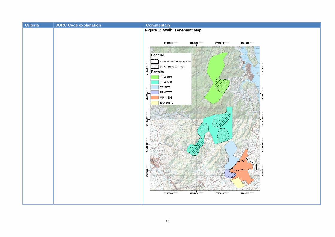
• The mineralisation occurs on granted permits Mining Permit 41808 and Exploration Permits 40767, 51771 and 40598.
• The Favona Mining Permit 41 808 (MP 41 808) was granted in March 2004, under the provisions of the Crown Minerals Act 1991, for a duration of 25 years. An Extension of Land to Favona MP 41 808 was granted in March 2006. The permit covers an area of 1485.38 hectares and covers the Correnso Underground Mine and Martha Open Pit mine.
• On MP 41808 the higher of a 1.0% royalty on net sales revenue from gold and silver or 5% accounting profits is payable to the Crown.
• EP 51771 is subject to a 1% Net Smelter Return royalty payable to Newmont Mining Corporation to a cap of 300,000oz gold.
• EP 40598, EP 40813 and EP 40767 are subject to a 2% royalty payable to BCKP Ltd (acquired from Geoinformatics) with respect to certain “target” areas.
Exploration done by other parties
• Acknowledgment and appraisal of exploration by other parties.
• Waihi Gold Company has held exploration and mining licences and permits over the Open Pit portion of the Martha deposit and the Favona and Trio deposits since the early 1980’s. The Waihi East area covering the Correnso deposit and easterly extensions of the Martha system was historically held and explored by Amoco Minerals, Cyprus Minerals and a Coeur Gold-Viking Mining JV from whom Waihi Gold Company purchased the permit area, EP40428, in 1998 for a cash settlement and a 2.5% royalty on the value of any mineral or metal produced from the property as outlined on the following map. OceanaGold has brought out this royalty thereby terminating the agreement with a total release from the royalty from April 1st 2016. These companies drilled approximately 18km in 60 holes in the Waihi East area by which they identified some remnant resources on the eastern end of the Martha vein system on which they undertook scoping studies.
• Previous exploration by Amoco and BP Minerals at WKP in the 1980s and 1990s was focused on sheeted stockwork veins exposed in stream channels through the prospect. Newmont as the operator of a WKP joint venture with Glass Earth in 2009-2013 identified and drilled several larger structures, encountering significant results in some holes. The Newmont/Glass Earth interest was subsequently purchased by OceanaGold.
15
Criteria JORC Code explanation Commentary
Figure 1: Waihi Tenement Map
16
Criteria JORC Code explanation Commentary
Geology • Deposit type, geological setting and style
of mineralisation.
• The Waihi deposits display features that are typical of epithermal gold deposits which include:
• Host lithologies for veins are andesite flows and volcaniclastics within the Waihi near mine setting while they are predominantly more felsic rhyolite flows to the north on the WKP prospect.
• Gold-silver mineralisation is hosted in localized bands within multiphase quartz veins. There is an association of sphalerite, galena and chalcopyrite with gold-silver mineralisation throughout the Waihi deposits, especially at Correnso. Parts of the Correnso deposit towards the base are base metal rich with galena (up to +3% Pb) and sphalerite (up to +1% Zn);
• Host andesitic volcanics at Waihi have undergone pervasive hydrothermal alteration, often with complete replacement of primary mineralogy. Characteristic alteration assemblages include quartz, albite, adularia, carbonate, pyrite, illite, chlorite, interlayered illite-smectite and chlorite-smectite clays extending over tens of metres laterally from major veins. There is also an association at Waihi of quartz + interlayered chlorite-smectite (corrensite) + chlorite, producing a distinctive pale green colouration. Mineralization is structurally controlled.
• Multiphase low sulphidation epithermal quartz veins at WKP are hosted in a rhyolitic flow dome complex with overlying and interfingering lithic lapilli tuffs. This flow dome complex occupies a northeast trending district-scale graben. These volcanics have undergone pervasive hydrothermal alteration, often with complete replacement of primary mineralogy by quartz and adularia with minor illite or smectite. The veins are structurally-controlled with two types of vein systems recognised. The first set of veins strike almost due north and consist of typically 1-100 centimetre wide banded quartz veins which occur in sheeted vein sets up to 150 metres wide in envelopes of quartz-adularia alteration. These veins do not appear to have significant lateral or vertical continuity. The second, more important vein set strike more north-easterly and occupy district-scale graben step faults. These quartz veins are up to 10 metres wide, more continuous and can contain significant gold grades over significant widths. In general, there are very few sulphides other than pyrite in the WKP veins.
Drill hole Information
• A summary of all information material to the understanding of the exploration results including a tabulation of the following information for all Material drill holes: o easting and northing of the drill hole collar o elevation or RL (Reduced Level –
elevation above sea level in metres) of the drill hole collar
o dip and azimuth of the hole o down hole length and interception depth o hole length.
• See Tables 1 to 4 in the announcement, which lists for each hole with a significant intercept, the hole ID, interception depth, downhole length and estimated true width of the intercept.
17
Criteria JORC Code explanation Commentary
• If the exclusion of this information is justified on the basis that the information is not Material and this exclusion does not detract from the understanding of the report, the Competent Person should clearly explain why this is the case.
Data aggregation methods
• In reporting Exploration Results, weighting averaging techniques, maximum and/or minimum grade truncations (e.g. cutting of high grades) and cut-off grades are usually Material and should be stated.
• Where aggregate intercepts incorporate short lengths of high grade results and longer lengths of low grade results, the procedure used for such aggregation should be stated and some typical examples of such aggregations should be shown in detail.
• The assumptions used for any reporting of metal equivalent values should be clearly stated.
• Exploration results are reported within distinct geological boundaries, typically within veins. The grades are compiled using length weighting with no top cutting.
Relationship between mineralisation widths and intercept lengths
• These relationships are particularly important in the reporting of Exploration Results.
• If the geometry of the mineralisation with respect to the drill hole angle is known, its nature should be reported.
• If it is not known and only the down hole lengths are reported, there should be a clear statement to this effect (e.g. ‘down hole length, true width not known’).
• Drill intercepts are reported as down hole length along with an estimated true width based on intercept angle to the mineralised veins. As much as practicable holes are designed to intersect veins at more than 60 degrees to the vein.
Diagrams • Appropriate maps and sections (with scales)
and tabulations of intercepts should be included for any significant discovery being reported These should include, but not be limited to a plan view of drill hole collar
• Refer to figures and tables in the body of the release and using the link in this press release to OGC’s website.

18
Criteria JORC Code explanation Commentary
locations and appropriate sectional views.
Balanced reporting
• Where comprehensive reporting of all Exploration Results is not practicable, representative reporting of both low and high grades and/or widths should be practiced to avoid misleading reporting of Exploration Results.
• The Waihi drill hole information is available from www.oceanagold.com.
Other substantive exploration data
• Other exploration data, if meaningful and material, should be reported including (but not limited to): geological observations; geophysical survey results; geochemical survey results; bulk samples – size and method of treatment; metallurgical test results; bulk density, groundwater, geotechnical and rock characteristics; potential deleterious or contaminating substances.
• Exploration drilling is continuing throughout the Waihi Epithermal Vein camp on MP 41808, EP 51771 and EP 40767. EP 40767 has been subject to a 60:40 JV arrangement with Glass Earth (New Zealand) Limited whose 40% interest in this permit and 35% interest in the Hauraki JV permits to the north are the subject of the exercise by OceanaGold of pre-emptive rights under the JV Agreements to acquire a 100% interest in the permits. Regulatory consent to the transaction has been received and the transfer of interests was completed in Q1 2016.
• Exploration drilling has also commenced this year to test the resource potential at WKP about 10km north of Waihi where previous explorers identified major gold bearing structures. Two holes have been completed to date with a third in progress.
Further work • The nature and scale of planned further work
(e.g. tests for lateral extensions or depth extensions or large-scale step-out drilling).
• Diagrams clearly highlighting the areas of possible extensions, including the main geological interpretations and future drilling areas, provided this information is not commercially sensitive.
• Current drill programmes are planned to complete 48km’s of diamond drilling for the calendar year 2017. Year to date 31,693m of these programmes have been completed with at least a further 16,000m scheduled for 2017. This drilling is comprised of infill on known vein systems (~80%), with the balance to step out on known veins and exploration in areas adjacent to known mineralisation. Drilling at WKP consists of step-out drilling along know large scale vein structures to test the resource potential of these areas.
19
JORC Code, 2012 Edition – Table 1, Haile Gold Mine Project
Section 1 Sampling Techniques and Data
(Criteria in this section apply to all succeeding sections)
Criteria JORC Code explanation Commentary
Sampling techniques
• Nature and quality of sampling (eg cut channels, random chips, or specific specialised industry standard measurement tools appropriate to the minerals under investigation, such as down hole gamma sondes, or handheld XRF instruments, etc). These examples should not be taken as limiting the broad meaning of sampling.
• Include reference to measures taken to ensure sample representivity and the appropriate calibration of any measurement tools or systems used.
• Aspects of the determination of mineralisation that are Material to the Public Report.
• In cases where ‘industry standard’ work has been done this would be relatively simple (eg ‘reverse circulation drilling was used to obtain 1 m samples from which 3 kg was pulverised to produce a 30 g charge for fire assay’). In other cases more explanation may be required, such as where there is coarse gold that has inherent sampling problems. Unusual commodities or mineralisation types (eg submarine nodules) may warrant disclosure of detailed information.
Diamond Drilling
• Diamond core drilling is by wireline methods and generally utilizes HQ and NQ size core 6.35cm and 4.8cm core. Core is transferred from the core barrels to plastic core boxes at the drill rig by the driller. Core orientation is not utilized other than for specific geotechnical programs. Core is broken as required to completely fill the boxes. Drill intervals are marked on the core boxes and interval marker blocks are labelled and placed in the core box. Whole core is transported to the sample preparation area by OceanaGold personnel.
Sample Preparation & Analysis Core Samples
• At the core logging facility, the core is cleaned, measured and photographed. Geotechnical and geologic logging is completed on the whole core. Rock Quality Data (RQD) and core recovery are recorded as part of the geotechnical suite of data.
• The logging geologist assigns the sample intervals and sample numbers prior to core sawing. Core is either sawed or split with a putty knife if soft. The saw or knife is cleaned between each sample. A brick or barren rock sample is sawed with the diamond saw between intervals to minimize cross-contamination. The cooling water for the saw is not recycled.
• Split core is delivered to the sample preparation facilities at the Kershaw Mineral Lab (KML) in Kershaw, South Carolina. KML is wholly owned by OceanaGold Corp.
• Sample preparation step include:
1) Inventory and log samples into the laboratory LIMS tracking system 2) Print worksheets and envelope labels 3) Dry samples at 93 degrees C 4) Jaw crush samples to 70% passing 10 mesh (2 mm) 5) Clean the crusher between samples with barren rock and compressed air 6) Split sample with a riffle splitter to prepare the sample for pulverizing 7) Pulverize a 450 gm sample (+/- 50 gm) to 85% passing 140 mesh (0.106 mm) 8) Clean the pulveriser between samples with sand and compressed air 9) Approximately 225 gm of pulp sample is sent for fire assay
20
Criteria JORC Code explanation Commentary
10) Coarse rejects and reserve pulps are returned to Haile for storage.
• Sample pulps from KML are analysed at KML. Check assays in for mineralized intervals were sent to ALS Minerals in Tucson for external verification.
Drilling techniques
• Drill type (eg core, reverse circulation, open-hole hammer, rotary air blast, auger, Bangka, sonic, etc) and details (eg core diameter, triple or standard tube, depth of diamond tails, face-sampling bit or other type, whether core is oriented and if so, by what method, etc).
• Drilling at the Haile property commenced in the 1970s and has continued intermittently to the present by several different companies.
• Diamond core drilling is by wireline methods and generally utilizes HQ and NQ size core 6.35cm and 4.8cm core.
Drill sample recovery
• Method of recording and assessing core and chip sample recoveries and results assessed.
• Measures taken to maximise sample recovery and ensure representative nature of the samples.
• Whether a relationship exists between sample recovery and grade and whether sample bias may have occurred due to preferential loss/gain of fine/coarse material.
• Core recoveries were measured at the core shed by the logging geologist. Core recoveries average 97%. There is no observed relationship between core recovery and grade.
Density • • Density measurements for drill core are recorded every 6 to 9m feet using the water
immersion method. Results are uploaded to the database and have been reviewed based on depth, grade, rock type, oxidation state, sulfide abundance and alteration. Density recommendations vary by rock type and have been coded into the block model.
Logging • Whether core and chip samples have been geologically and geotechnically logged to a level of detail to support appropriate Mineral Resource estimation, mining studies and metallurgical studies.
• All drilled intervals are logged on site by staff geologists at Haile Gold Mine. Geotechnical and geologic logging are completed on washed whole core.
• Geologic logging includes rock type, structure, alteration and mineralogy, with comments.
• Rock Quality Data (RQD), hardness, fracture frequency and joint condition rating and core recovery are recorded as part of the geotechnical suite of data.
21
Criteria JORC Code explanation Commentary
• Whether logging is qualitative or quantitative in nature. Core (or costean, channel, etc) photography.
• The total length and percentage of the relevant intersections logged.
• All core intervals are photographed and stored on the Haile network.
• All logging is recorded via MS tablets in Excel files with a separate file for each drill hole. The data are stored on site and backed up daily. Excel files are uploaded to the acQuire database.
Sub-sampling techniques and sample preparation
• If core, whether cut or sawn and whether quarter, half or all core taken.
• If non-core, whether riffled, tube sampled, rotary split, etc and whether sampled wet or dry.
• For all sample types, the nature, quality and appropriateness of the sample preparation technique.
• Quality control procedures adopted for all sub-sampling stages to maximise representivity of samples.
• Measures taken to ensure that the sampling is representative of the in situ material collected, including for instance results for field duplicate/second-half sampling.
• Whether sample sizes are appropriate to the grain size of the material being sampled
• Refer to sampling techniques section or the Quality of Assay data section for more detail.
• Half core samples are cut by rotary diamond saw or, if too soft, are cut by knife. Half core is placed in a bar-coded, labelled sample bag and the other half is returned to the core box.
• It is believed that preparation for both the diamond core and RC samples is appropriate.
• It is believed that the sample sizes are adequate for the Haile deposits, which are primarily of the finely disseminated sediment-hosted style. Although coarse gold has been observed in drill core, it is rare and is not representative of the mineralization that will be mined.
Quality of assay data and laboratory tests
• The nature, quality and appropriateness of the assaying and laboratory procedures used and whether the technique is considered partial or total.
• For geophysical tools, spectrometers, handheld XRF instruments, etc, the parameters used in determining the analysis including instrument make and model, reading times, calibrations factors applied and their derivation, etc.
• Nature of quality control procedures adopted (eg standards, blanks, duplicates, external
• The Mineral Resources and Ore Reserves at Haile are based on fire assay of a 30 gm aliquot for gold with Atomic Absorption finish <3 g/t Au and gravity finish >3 g/t Au. Blanks and standards, are inserted, and check assays are submitted to a second lab on a regular basis.
22
Criteria JORC Code explanation Commentary
laboratory checks) and whether acceptable levels of accuracy (ie lack of bias) and precision have been established.
Verification of sampling and assaying
• The verification of significant intersections by either independent or alternative company personnel.
• The use of twinned holes.
• Documentation of primary data, data entry procedures, data verification, data storage (physical and electronic) protocols.
• Discuss any adjustment to assay data.
• There are strong visual indicators for mineralisation observed in drill core based on intensity of silicification, pyrite abundance and hydrothermal brecciation.
• All assay data is stored in a secure acQuire database in an as received basis with no adjustment made to the returned data.
Location of data points
• Accuracy and quality of surveys used to locate drill holes (collar and down-hole surveys), trenches, mine workings and other locations used in Mineral Resource estimation.
• Specification of the grid system used.
• Quality and adequacy of topographic control.
• Drill hole collars are surveyed with differential GPS with sub-centimetre accuracy. The historic Amax and early Romarco holes were surveyed by a South Carolina licensed surveyor using conventional ground methods. Check surveys have been completed during the project.
• The drill hole locations and the project coordinate system are UTM NAD83 zone 17N.
• Topographic control has been established to a high level of precision. Resource estimation and mine planning relied on contour maps with 0.6m contour intervals.
Data spacing and distribution
• Data spacing for reporting of Exploration Results.
• Whether the data spacing and distribution is sufficient to establish the degree of geological and grade continuity appropriate for the Mineral Resource and Ore Reserve estimation procedure(s) and classifications applied.
• Whether sample compositing has been applied.
• Drill hole spacing is not a simple calculation at Haile because many holes are angle holes and down hole deflections occur during the drilling process. Several angle holes were often drilled from a single drill platform. Drill hole spacing is sufficient to enable grade distribution and geological controls to be established with a high degree of confidence for the Haile disseminated style of mineralisation.
Orientation of data in relation to
• Whether the orientation of sampling achieves unbiased sampling of possible
• The orientation of the mineralisation generally parallels the foliation of the host metasediments. The metasediments have variable dip that ranges between 20 degrees to the north-northwest to vertical. Mineralisation dips 30 to 60 degrees to the northwest. Drill

23
Criteria JORC Code explanation Commentary
geological structure
structures and the extent to which this is known, considering the deposit type.
• If the relationship between the drilling orientation and the orientation of key mineralised structures is considered to have introduced a sampling bias, this should be assessed and reported if material.
holes are typically angled at -500 to -600 southeast in order to intercept mineralisation perpendicular to mineralised trends.
• Drill holes deviate perpendicular to the northwest-dipping foliation and mineralisation. There is no evidence of orientation-related sample bias at Haile.
Sample security
• The measures taken to ensure sample security.
• All drill hole samples are transported from the drill rigs to the fenced Haile Exploration warehouse by OGC personnel. Access to the property is controlled by locked doors and cameras. When samples are trucked to the lab the sample manifests are checked by the lab and the receipt of all samples are confirmed. Samples are packaged at the Haile Exploration warehouse by the Geotech Supervisor. Samples are trucked in sealed plastic barrels by certified couriers with submittal forms that are verified at sample collection and delivery.
Audits or reviews
• The results of any audits or reviews of sampling techniques and data
• Audits and reviews have been performed by independent consultants prior to previous resource estimations. Collar coordinates, downhole surveys and assay certificates have been confirmed for drill hole data reported herein. Sample preparation and assaying were performed by ALS laboratories in Tucson, AZ, and Reno, NV. Quarterly review of QAQC drill hole data has confirmed excellent precision and no evidence of sample contamination.
24
Section 2 Reporting of Exploration Results
(Criteria listed in the preceding section also apply to this section)
Criteria
Commentary
Mineral tenement and land tenure status
• Type, reference name/number, location and ownership including agreements or material issues with third parties such as joint ventures, partnerships, overriding royalties, native title interests, historical sites, wilderness or national park and environmental settings.
• The security of the tenure held at the time of reporting along with any known impediments to obtaining a licence to operate in the area.
Property Location
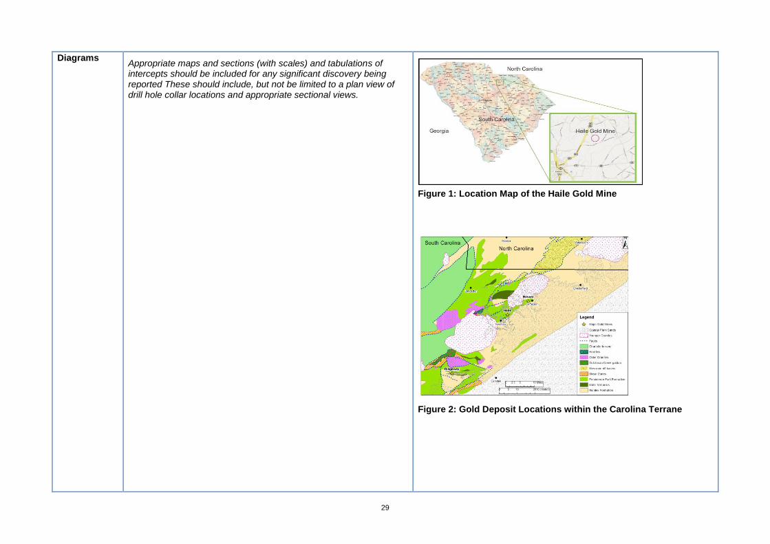
• The Haile property site is located 4.8km (3mi) northeast of the town of Kershaw in southern Lancaster County, South Carolina. Lancaster County lies in the north-central part of the state. The Haile Gold Mine is approximately 27.4 km (17 mi) southeast of the city of Lancaster, the county seat, which is approximately 48.3 km (30 mi) south of Charlotte, North Carolina. The approximate geographic centre of the property is at 34° 34’ 46” N latitude and 80° 32’ 37” W longitude. The mineralized zones at Haile lie within an area extending from 538000 E to 544000 E, and from 3825000 N to 3828000N (UTM NAD83 zone 17N).
• Following a Plan of Arrangement completed on October 1st, 2015 between Romarco Minerals Inc and OceanaGold Corporation, Haile Gold Mine Inc. (HGM) is a wholly owned subsidiary of OceanaGold Corporation. References in this document to OceanaGold refer to the parent company together with its subsidiaries, including HGM and Romarco Minerals Inc.
• HGM provided an inventory of property that is owned both within the project boundary and as buffer land outside the project boundary. After transferring approximately 4,388 acres of land into mitigation and conservancy projects, HGM owns 5,919 acres of land. HGM owns and leases additional land that part of the Haile mine.
Exploration done by other parties
• Acknowledgment and appraisal of exploration by other parties. • Historic exploration was completed prior to acquisition of the Haile Gold Mine by Romarco, Piedmont and others. That work has been superseded by the drilling completed at Haile by OceanaGold since 2015.
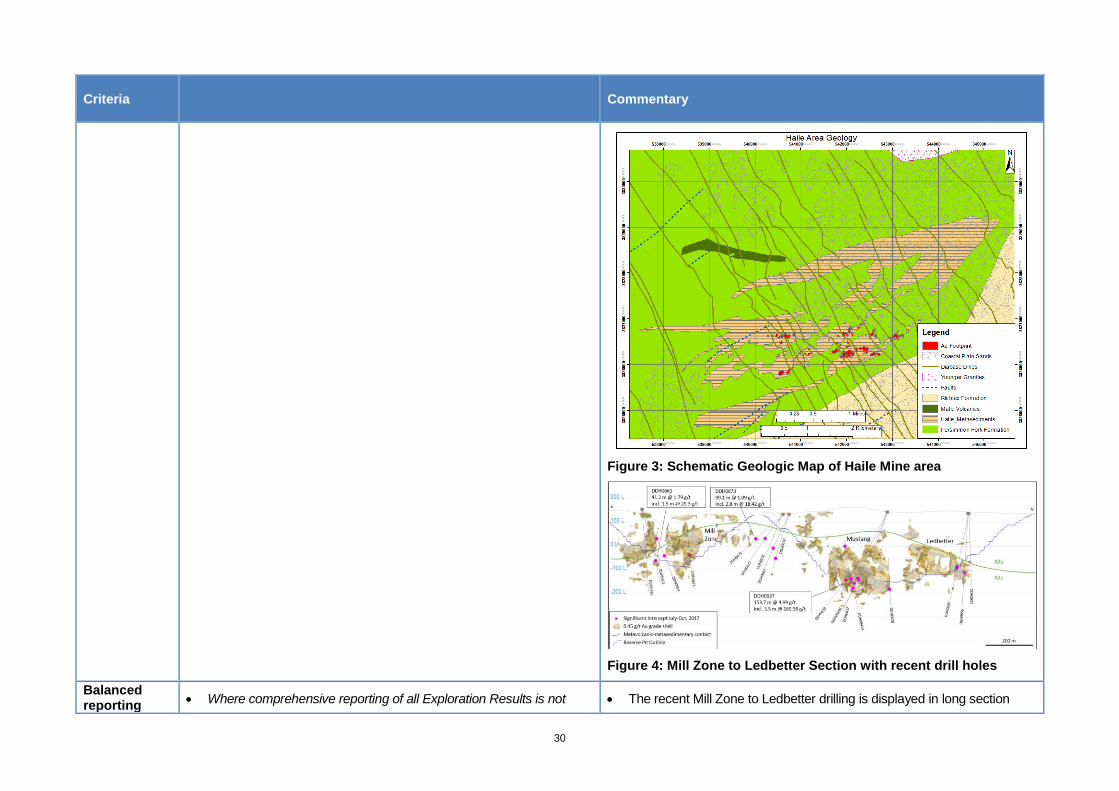
Geology • Deposit type, geological setting and style of mineralisation. • Numerous gold deposits are located along a northeast trend that
extends from eastern Georgia to Virginia. Many of these deposits are located at or near the contact between felsic volcanics and sedimentary dominated sequences. Various metal associations and
25
Criteria
Commentary
mineralisation styles indicate that this is a complex metallogenic province. Brewer has many features of a high sulphidation system with the presence of abundant pyrite, aluminosilicates, topaz and enargite. Gold mineralisation at Barite Hill contains the assemblage of pyrite-chalcopyrite-galena-sphalerite and is characteristic of a submarine, high-sulphidation volcanogenic massive sulphide deposit. Haile and Ridgeway are similar in that the mineralisation is hosted within silicified siltstones interbedded with volcaniclastic rocks of the Neoproterozoic Upper Persimmon Fork Formation. Both deposits contain disseminated gold mineralisation that correlates with anomalous silver, arsenic, antimony, molybdenum and tellurium.
• The genesis of Haile and Ridgeway is controversial and has been exacerbated by poor exposures, overprinting deformation, metamorphism, and intense weathering. Submarine hot springs have been suggested for the gold mineralisation by several geologists (Worthington and Kiff, 1970; Spence et al., 1980; and Kiff and Spence, 1987). Foley et al. (2001) and Ayuso et al. (2005) have presented additional evidence in support of this model which include geochemistry of sulphide phases and geochronology. The exhalative model stipulates that gold deposition occurred when “black smokers” on the sea floor fumed out silica, gold, and sulphide bearing fluids and the minerals precipitated in a wide area over a uniform seafloor. The precipitated minerals were buried by later sedimentation. The gold deposits are disseminated, stratiform and lenticular in shape and dominantly sediment-hosted.
• Alternatively, several workers have proposed the mineralisation is structurally controlled and was caused by deformation. Tomkinson (1990) proposed that shearing was responsible for the mineralisation at Haile and Ridgeway. This model invokes shears as the conduit for focusing gold bearing fluids into the metasiltstones. Drops in pressure during faulting are speculated to be responsible for gold precipitation. Nick Hayward (1992) proposed that folding of the phyllites controlled the gold mineralisation. This genetic model proposes that gold was emplaced within the dilational zones of fold hinges during deformation.
• Gillon et al. (1995) proposed a model which invoked both early
26
Criteria
Commentary
mineralisation and remobilization during deformation. O’Brien et al. (1998) proposed that the deposits were generated during the Neoproterozoic by the arc related volcanic activity in a hydrothermal system. This is supported by the close spatial associations between Haile and the felsic volcanic rocks. Pressure shadows around pyrite grains within the mineralized zones, folded mineralized zones, and flattened hydrothermal breccias indicate that the mineralisation is pre-tectonic and rules out that the mineralisation is related to deformation as proposed by Tomkinson and Hayward. Hydrothermal breccias containing well bedded clasts, silicification fronts cross-cutting bedding, and multiple phases of silicification indicate that the mineralisation is post depositional and invalidate the submarine hot springs or exhalative model.
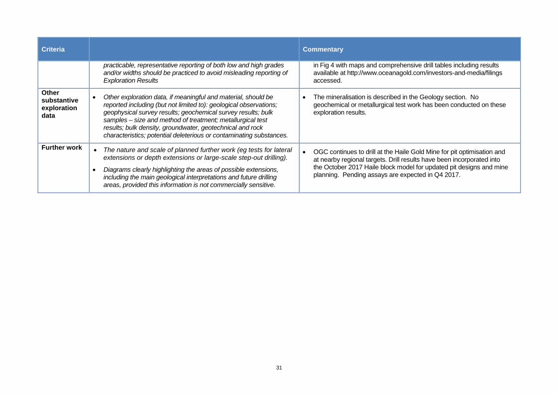
• Recent stratigraphic reinterpretation by OceanaGold geologists has reassigned the metasedimentary package at Haile from the Richtex Formation to the uppermost section of the Persimmon Fork Formation (Maddry and Kilbey, 1995). This is supported by fining upward sedimentary cycles, gradational contacts, rapid facies change, tuffaceous interbeds and the occurrence of 1-3% plagioclase crystals in volcaniclastic units. The conformable ENE-trending contact between the Persimmon Fork and the overlying Richtex Formation is located about 0.5 km south of Haile (figure 3). Reinterpretation of stratigraphy at Haile considerably simplifies the previous structural model with a folded volcanic-sedimentary package that is not complicated by overturned bedding or regional thrusting.
• Similar timing for gold mineralization and peak magmatism in the Haile and Ridgeway areas indicates that the hydrothermal systems that produced these deposits were driven by magmatism and therefore were not the product of collision, orogeny, and/or a related metamorphic event. Gold mineralization at Haile (~549 Ma, Mobley et al., 2014) slightly postdates volcanism, which precludes syngenetic and volcanogenic models and predates deformation. Gold mineralization coincides with a major tectonostratigraphic change from intermediate volcanism and tuffaceous sedimentation to basinal turbiditic sedimentation. Haile is classified by OceanaGold
27
Criteria
Commentary
geologists as a disseminated, sediment-hosted, intrusion-related gold deposit with proximal quartz-sericite-pyrite (QSP) alteration and distal sericite-chlorite alteration. (Robert et al., 2007). Haile is hosted by reduced siliciclastic rocks with less permeable volcanic caprocks, is folded and faulted, and has early K feldspar and silica-pyrite alteration with late sericite-carbonate, and is spatially associated with granitic intrusions.
Drill hole Information
• A summary of all information material to the understanding of the exploration results including a tabulation of the following information for all Material drill holes:
o easting and northing of the drill hole collar o elevation or RL (Reduced Level – elevation above sea level in
metres) of the drill hole collar o dip and azimuth of the hole o down hole length and interception depth o hole length.
• If the exclusion of this information is justified on the basis that the information is not Material and this exclusion does not detract from the understanding of the report, the Competent Person should clearly explain why this is the case.
• See Table 1 in the announcement, which lists for each hole with a significant intercept, the hole ID, easting, northing, collar RL, azimuth, dip, interception depth and downhole length.
Data aggregation methods
• In reporting Exploration Results, weighting averaging techniques, maximum and/or minimum grade truncations (eg cutting of high grades) and cut-off grades are usually Material and should be stated.
• Where aggregate intercepts incorporate short lengths of high grade results and longer lengths of low grade results, the procedure used for such aggregation should be stated and some typical examples of such aggregations should be shown in detail.
• The assumptions used for any reporting of metal equivalent values should be clearly stated.
• Exploration results are reported within distinct geological boundaries. The grades are compiled using length weighting with no top cutting.
Relationship between mineralisation widths and
• These relationships are particularly important in the reporting of Exploration Results.
• If the geometry of the mineralisation with respect to the drill hole angle is known, its nature should be reported.
• Drill intercepts are reported in down hole length from the drill collar. Most are 1.5m (5 ft) long assay intervals. The intercept lengths may not correspond to true widths due to holes that do not cross perpendicular to the mineralisation. True widths are typically 60-80%
28
Criteria
Commentary
intercept lengths
• If it is not known and only the down hole lengths are reported, there should be a clear statement to this effect (eg ‘down hole length, true width not known’).
of the reported drill widths, and vary according to drill hole intersection angles with foliation and bedding.
29
Diagrams Appropriate maps and sections (with scales) and tabulations of intercepts should be included for any significant discovery being reported These should include, but not be limited to a plan view of drill hole collar locations and appropriate sectional views.
Figure 1: Location Map of the Haile Gold Mine
Figure 2: Gold Deposit Locations within the Carolina Terrane
30
Criteria
Commentary
Figure 3: Schematic Geologic Map of Haile Mine area
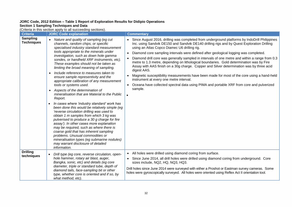
Figure 4: Mill Zone to Ledbetter Section with recent drill holes
Balanced reporting
• Where comprehensive reporting of all Exploration Results is not • The recent Mill Zone to Ledbetter drilling is displayed in long section
31
Criteria
Commentary
practicable, representative reporting of both low and high grades and/or widths should be practiced to avoid misleading reporting of Exploration Results
in Fig 4 with maps and comprehensive drill tables including results available at http://www.oceanagold.com/investors-and-media/filings accessed.
Other substantive exploration data
• Other exploration data, if meaningful and material, should be reported including (but not limited to): geological observations; geophysical survey results; geochemical survey results; bulk samples – size and method of treatment; metallurgical test results; bulk density, groundwater, geotechnical and rock characteristics; potential deleterious or contaminating substances.
• The mineralisation is described in the Geology section. No geochemical or metallurgical test work has been conducted on these exploration results.
Further work • The nature and scale of planned further work (eg tests for lateral extensions or depth extensions or large-scale step-out drilling).
• Diagrams clearly highlighting the areas of possible extensions, including the main geological interpretations and future drilling areas, provided this information is not commercially sensitive.
• OGC continues to drill at the Haile Gold Mine for pit optimisation and at nearby regional targets. Drill results have been incorporated into the October 2017 Haile block model for updated pit designs and mine planning. Pending assays are expected in Q4 2017.
32
JORC Code, 2012 Edition – Table 1 Report of Exploration Results for Didipio Operations Section 1 Sampling Techniques and Data (Criteria in this section apply to all succeeding sections).
Criteria JORC Code explanation Commentary
Sampling Techniques
• Nature and quality of sampling (eg cut channels, random chips, or specific specialised industry standard measurement tools appropriate to the minerals under investigation, such as down hole gamma sondes, or handheld XRF instruments, etc). These examples should not be taken as limiting the broad meaning of sampling.
• Include reference to measures taken to ensure sample representivity and the appropriate calibration of any measurement tools or systems used.
• Aspects of the determination of mineralisation that are Material to the Public Report.
• In cases where ‘industry standard’ work has been done this would be relatively simple (eg ‘reverse circulation drilling was used to obtain 1 m samples from which 3 kg was pulverised to produce a 30 g charge for fire assay’). In other cases more explanation may be required, such as where there is coarse gold that has inherent sampling problems. Unusual commodities or mineralisation types (eg submarine nodules) may warrant disclosure of detailed information.
• Since August 2016, drilling was completed from underground platforms by IndoDrill Philippines Inc. using Sandvik DE150 and Sandvik DE140 drilling rigs and by Quest Exploration Drilling using an Atlas Copco Diamec U6 drilling rig.
• Diamond core sampling intervals were defined after geological logging was completed.
• Diamond drill core was generally sampled in intervals of one metre and within a range from 0.3 metre to 1.3 metre, depending on lithological boundaries. Gold determination was by Fire Assay with AAS finish on a 30g charge. Copper and Silver determination was by three acid digest AAS.
• Magnetic susceptibility measurements have been made for most of the core using a hand-held instrument at every one metre interval.
• Oceana have collected spectral data using PIMA and portable XRF from core and pulverized sample.
•
Drilling techniques
• Drill type (eg core, reverse circulation, open-hole hammer, rotary air blast, auger, Bangka, sonic, etc) and details (eg core diameter, triple or standard tube, depth of diamond tails, face-sampling bit or other type, whether core is oriented and if so, by what method, etc).
• All holes were drilled using diamond coring from surface.
• Since June 2014, all drill holes were drilled using diamond coring from underground. Core sizes include, NQ2, HQ, NQ3, HQ3.
Drill holes since June 2014 were surveyed with either a Proshot or Eastman survey cameras. Some holes were gyroscopically surveyed. All holes were oriented using Reflex Act II orientation tool.
33
Criteria JORC Code explanation Commentary
Drill sample recovery
• Method of recording and assessing core and chip sample recoveries and results assessed.
• Measures taken to maximise sample recovery and ensure representative nature of the samples.
• Whether a relationship exists between sample recovery and grade and whether sample bias may have occurred due to preferential loss/gain of fine/coarse material.
• Core recoveries were measured after each drill run comparing length of core recovered vs drill depth.
• Core recoveries were generally better than 95%. No strong relationship between core recovery and grade is evident.
Logging • Whether core and chip samples have been geologically and geotechnically logged to a level of detail to support appropriate Mineral Resource estimation, mining studies and metallurgical studies.
• Whether logging is qualitative or quantitative in nature. Core (or costean, channel, etc) photography.
• The total length and percentage of the relevant intersections logged.
• All core has been digitally photographed (wet and dry). The core is stored at Didipio site and so can be referred to in these cases.
• All core drilled since June 2014 has been logged using OGC procedure.
Sub-sampling techniques and sample preparation
• If core, whether cut or sawn and whether quarter, half or all core taken.
• If non-core, whether riffled, tube sampled, rotary split, etc and whether sampled wet or dry.
• For all sample types, the nature, quality and appropriateness of the sample preparation technique.
• Quality control procedures adopted for all sub-sampling stages to maximise representivity of samples.
• Measures taken to ensure that the sampling is representative of the in situ material collected, including for instance results for field duplicate/second-half sampling.
• Only half cores were taken for assay except where mentioned otherwise.
• The following sampling preparation methodologies are believed to be appropriate to the style of mineralisation at Didipio. Gold particle size is typically fine.
• For the 2016 Resource Extension drilling program (DDDH 240, DDDH241A, and DDDH242), the diamond core was cut and prepared at 1 metre intervals at Didipio. Minimum length allowed for sampling interval is 0.3m. HQ cores were cut in half, whereas NQ core were sampled whole. Cores were submitted to the SGS facility on site. SGS sample preparation procedure is as follows:
o Oven dry core samples (min of 8hrs at ~105 degree Celsius);
o PRP90 (weighing of samples in calico bag)
o Crushed core to 75% passing 2mm;
o Rotary split to 500g – 1000g, retain coarse reject;
o Pulverize 500g – 1000g to 85% passing 75μm;
o Scoop 250g for analysis; retain pulp reject.
• For the 2016 Resource Definition drilling program, the diamond core was cut and prepared at 1 metre intervals at Didipio. Minimum length allowed of sampling interval is

34
Criteria JORC Code explanation Commentary
Whether sample sizes are appropriate to the grain size of the material being sampled.
0.3m. HQ cores were cut in half, whereas NQ core were crushed whole. Crushed core were submitted to the SGS facility on site. SGS sample preparation procedure is as follows:
o Oven dry core samples;
o Crushed core to 75% passing 2mm;
o Rotary split to 500g – 1000g, retain coarse reject;
o Pulverize 500g – 1000g to 85% passing 75μm;
o Scoop 250g for analysis; retain pulp reject.
UNDERGROUND DRILLING PROGRAM – RESOURCE EXTENSION AND RESOURCE DEFINITION QAQC
Standards – SGS Laboratory
Tables presented below show the overall performance of CRMs used in UG core drilling program for Resource Extension and Definition June-September 2017.
All CRMs in Au and Cu manifest acceptable to good performance based on average Z-score and absolute average z-score of each CRM.

35
Criteria JORC Code explanation Commentary
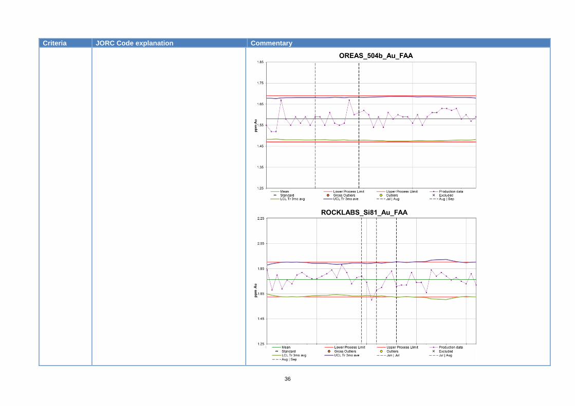
36
Criteria JORC Code explanation Commentary
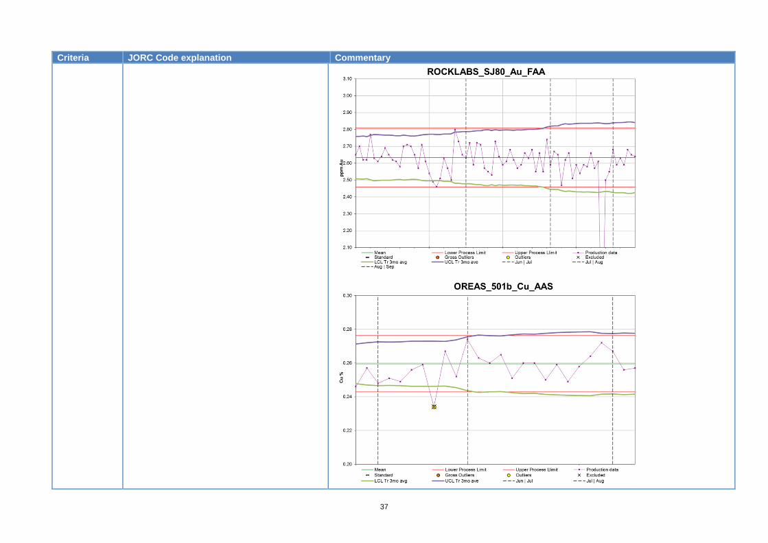
37
Criteria JORC Code explanation Commentary
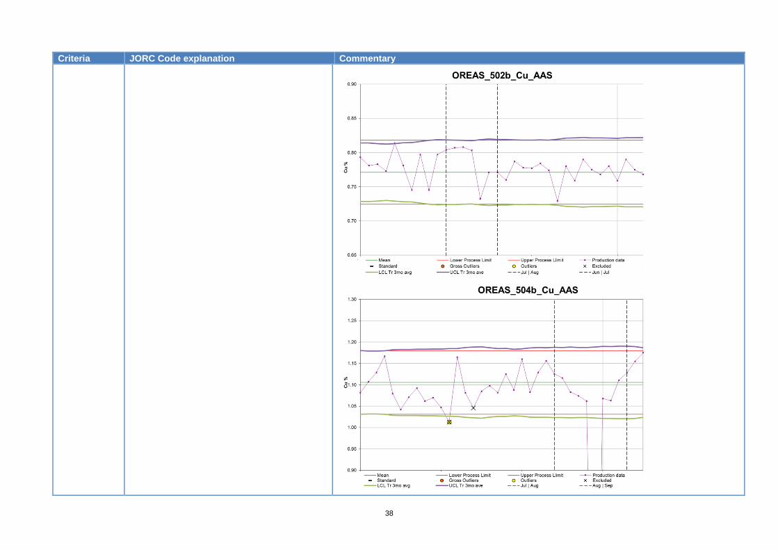
38
Criteria JORC Code explanation Commentary

39
Criteria JORC Code explanation Commentary
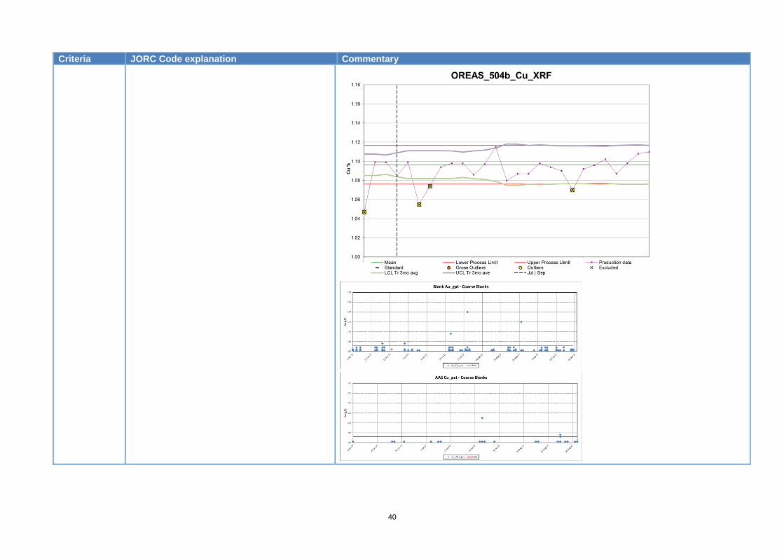
40
Criteria JORC Code explanation Commentary
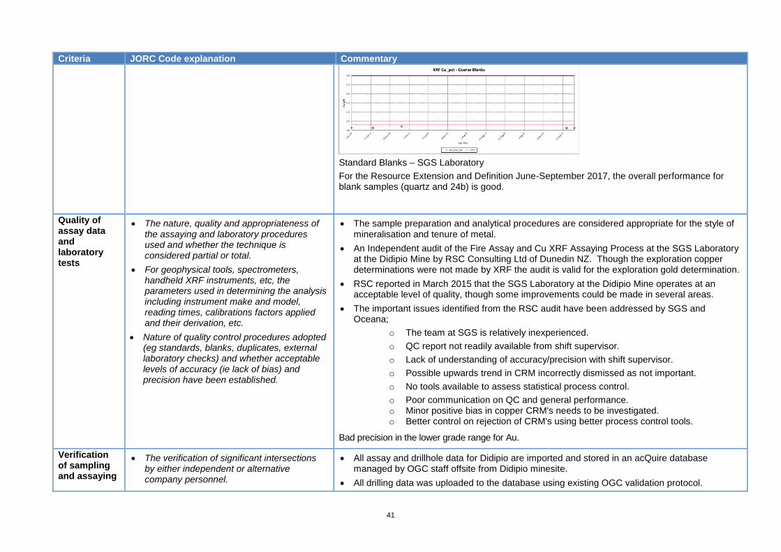
41
Criteria JORC Code explanation Commentary
Standard Blanks – SGS Laboratory
For the Resource Extension and Definition June-September 2017, the overall performance for blank samples (quartz and 24b) is good.
Quality of assay data and laboratory tests
• The nature, quality and appropriateness of the assaying and laboratory procedures used and whether the technique is considered partial or total.
• For geophysical tools, spectrometers, handheld XRF instruments, etc, the parameters used in determining the analysis including instrument make and model, reading times, calibrations factors applied and their derivation, etc.
• Nature of quality control procedures adopted (eg standards, blanks, duplicates, external laboratory checks) and whether acceptable levels of accuracy (ie lack of bias) and precision have been established.
• The sample preparation and analytical procedures are considered appropriate for the style of mineralisation and tenure of metal.
• An Independent audit of the Fire Assay and Cu XRF Assaying Process at the SGS Laboratory at the Didipio Mine by RSC Consulting Ltd of Dunedin NZ. Though the exploration copper determinations were not made by XRF the audit is valid for the exploration gold determination.
• RSC reported in March 2015 that the SGS Laboratory at the Didipio Mine operates at an acceptable level of quality, though some improvements could be made in several areas.
• The important issues identified from the RSC audit have been addressed by SGS and Oceana;
o The team at SGS is relatively inexperienced.
o QC report not readily available from shift supervisor.
o Lack of understanding of accuracy/precision with shift supervisor.
o Possible upwards trend in CRM incorrectly dismissed as not important.
o No tools available to assess statistical process control.
o Poor communication on QC and general performance. o Minor positive bias in copper CRM's needs to be investigated. o Better control on rejection of CRM's using better process control tools.
Bad precision in the lower grade range for Au.
Verification of sampling and assaying
• The verification of significant intersections by either independent or alternative company personnel.
• All assay and drillhole data for Didipio are imported and stored in an acQuire database managed by OGC staff offsite from Didipio minesite.
• All drilling data was uploaded to the database using existing OGC validation protocol.
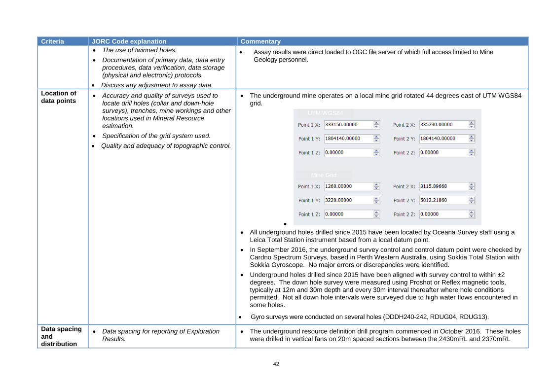
42
Criteria JORC Code explanation Commentary
• The use of twinned holes.
• Documentation of primary data, data entry procedures, data verification, data storage (physical and electronic) protocols.
• Discuss any adjustment to assay data.
• Assay results were direct loaded to OGC file server of which full access limited to Mine Geology personnel.
Location of data points
• Accuracy and quality of surveys used to locate drill holes (collar and down-hole surveys), trenches, mine workings and other locations used in Mineral Resource estimation.
• Specification of the grid system used.
• Quality and adequacy of topographic control.
• The underground mine operates on a local mine grid rotated 44 degrees east of UTM WGS84 grid.
•
• All underground holes drilled since 2015 have been located by Oceana Survey staff using a Leica Total Station instrument based from a local datum point.
• In September 2016, the underground survey control and control datum point were checked by Cardno Spectrum Surveys, based in Perth Western Australia, using Sokkia Total Station with Sokkia Gyroscope. No major errors or discrepancies were identified.
• Underground holes drilled since 2015 have been aligned with survey control to within ±2 degrees. The down hole survey were measured using Proshot or Reflex magnetic tools, typically at 12m and 30m depth and every 30m interval thereafter where hole conditions permitted. Not all down hole intervals were surveyed due to high water flows encountered in some holes.
• Gyro surveys were conducted on several holes (DDDH240-242, RDUG04, RDUG13).
Data spacing and distribution
• Data spacing for reporting of Exploration Results.
• The underground resource definition drill program commenced in October 2016. These holes were drilled in vertical fans on 20m spaced sections between the 2430mRL and 2370mRL
UTM WGS84
Mine Grid
43
Criteria JORC Code explanation Commentary
• Whether the data spacing and distribution is sufficient to establish the degree of geological and grade continuity appropriate for the Mineral Resource and Ore Reserve estimation procedure(s) and classifications applied.
Whether sample compositing has been applied.
mining levels. The holes on each fan were designed with a vertical spacing of no more than 25m within the zone of mineralisation.
• The resource extension holes were drilled beneath existing drill information.
Orientation of data in relation to geological structure
• Whether the orientation of sampling achieves unbiased sampling of possible structures and the extent to which this is known, considering the deposit type.
• If the relationship between the drilling orientation and the orientation of key mineralised structures is considered to have introduced a sampling bias, this should be assessed and reported if material.
The mineralization package at Didipio has a steep easterly dip. All holes were drilled from the
underground development on the western side of the mineralization package.
Sample security
• The measures taken to ensure sample security.
• All core drilled by OGC has been cut and dispatched by OGC personnel.
• All core and sample rejects since 2013 are stored on site.
Audits or reviews
• The results of any audits or reviews of sampling techniques and data
• The last independent review was by Hellman and Schofield as part of Oceana’s initial TSX lodging in 2007. All data collected since that time have only been subject to OGC’s internal operational QAQC procedures (ie insertion and monitoring of of blanks, standards, laboratory and field split duplicates).
• Oceana maintains the Didipio drill database.
• Original data documentation is stored electronically.
Oceana operates a QAQC program with duplicates, standards and blanks.

44
Section 2 Reporting of Exploration Results (Criteria listed in the preceding section also apply to this section).
Criteria JORC Code explanation Commentary
Mineral tenement and land tenure status
• Type, reference name/number, location and ownership including agreements or material issues with third parties such as joint ventures, partnerships, overriding royalties, native title interests, historical sites, wilderness or national park and environmental settings.
• The security of the tenure held at the time of reporting along with any known impediments to obtaining a licence to operate in the area.
• The Didipio gold-copper project is located in the north of Luzon Island approximately 270 km NNE of Manila, in the Philippines.
• The Didipio gold-copper project is at 121.45º E 16.33º N (Longitude/Latitude – World Geodetic System1984).
• The FTAA and proposed mining areas straddle a provincial boundary, with part of these properties within Barangay Didipio, Municipality of Kasibu, Province of Nueva Vizcaya and part within Barangay Dingasan, Municipality of Cabarroguis, Province of Quirino.
• The Financial or Technical Assistance Agreement (FTAA) now covers about 12,864 hectares (compared to the original 37,000 hectares) located in the Provinces of Nueva Vizcaya and Quirino. Parts of the original FTAA have been relinquished under the terms of the agreement that requires 10% relinquishment per annum.
• The mining area comprises 12 blocks (0.5’ latitude by 0.5’ longitude, or approximately 81 hectares each) or 9.75 km2 within the FTAA. A direct impact zone of 3.25 km2 is situated inside this 9.75km2 area.
• The FTAA was granted on 20 June 1994 for a 25-year period, renewable for a further 25 years. The FTAA carries a minimum expenditure commitment of US$50 million and includes the fiscal regime for any development. The expenditure commitment will easily be met as the capital cost of building the Didipio mining project exceeds this amount.
• The FTAA was originally granted to CAMC but was assigned to APMI in 2004 (which then changed its name to OGPI in 2007).
• The Environmental Compliance Certificate (ECC) for the project was originally granted to CAMC in August 1999, with subsequent amendments in January 2000 (extension of area) and August 2004 (definition of direct impact zone).
• The ECC allows for open pit and underground workings, tailings dam and impoundment, waste rock dumps, mill plant, explosive magazine, administration and housing facilities.
• The ECC specifies the project mining methods, production rate, processing methods and other aspects of the mining operation.
• Mining operation. It also specifies the environmental management and protection requirements, including the submission of Annual Environmental Program Enhancement Plans (AEPEPs) as well as a Social Development and Management Program.
• In March 2005, APMI submitted a Partial Declaration of Mining Project Feasibility (PDMF) for approval by the Department of Environment and Natural Resources (DENR). In conjunction
45
Criteria JORC Code explanation Commentary
with the PDMF, APMI submitted (among other things) a Definitive Feasibility Study for the project as well as Development Work Program (DWP).
• In October 2005, the PDMF was approved by the DENR which provided, in effect, the permit to operate and develop the project. The development period under the PDMF was subsequently extended for a further 3 years period from October 2009.
• An application to amend the ECC to reflect operations as outlined in this report was lodged with EMB in June 2011. Securing the last permits and approvals required will not be possible until all design details have been finalized, allowing the various construction permits, and subsequent permits-to-operate, to be granted. Land acquisition is almost complete and applications for water rights have been made and are in process.
• OGC acquired its interest in the Didipio Project as a result of its merger with Climax Mining Limited. OGC’s wholly owned subsidiary, Australasian Philippines Mining Inc (APMI), holds the FTAA that covers the Didipio Project area. Subsequently, APMI changed its name to OceanaGold (Philippines), Inc. (OGPI).
• OGPI has an agreement (known as the “Addendum Agreement”) (Jorge G Gonzales, Jerome P Delosa and David Gonzales) with a Philippine claim owner syndicate in respect to a substantial proportion of the FTAA, including the proposed mining area in its entirety (the “Addendum Property”). The claim owner syndicate has a contractual right, subject to satisfaction of certain conditions, to an 8% free carried interest in the operating vehicle that will be formed to undertake operations in respect of the Addendum Property.
• Upon the commencement of commercial production, there is a period of five years whereby the company can recover all pre-operating expenses (the Recovery Period). After this time, 60% of net profit (net of all taxes, local payments, government payments, etc) is payable to the government as a government share.
• The Company has acquired, through voluntary agreements, the surface rights to the all the land required for the Project for the foreseeable future.
• The claim owner syndicate (Gonzales) is entitled to a 2% net smelter return (NSR) royalty on production from the Addendum Property under the terms of the Addendum Agreement.
• A 0.6% of 92% NSR royalty (capped at a total of A$13.5 million) is payable to Malaysian Mining Corporation.
• The author is unaware of any further royalties, back-in rights, payments or other agreements and encumbrances that apply to the Didipio Project.
• An amended Environmental Impact Statement (EIS) was completed by Gaia South Inc, environmental consultants, on behalf of CAMC in April 2004, which led to the issuance of the revised ECC on 8 August 2004.
46
Criteria JORC Code explanation Commentary
• The revised ECC sets out the work requirements relating to environmental management and protection requirements, which includes an Environmental Trust Fund, Environmental Risk Assessment and Mine Decommissioning Plan.
• A submission to vary the existing ECC was lodged on 1 June 2011 with the EMB in Manila to address project changes made since the granting of the 2004 ECC. A revised ECC was issued in December 2012.
Exploration done by other parties
• Acknowledgment and appraisal of exploration by other parties.
• The Didipio area was first recognised as a gold province in the 1970s, when indigenous miners discovered alluvial gold deposits in the region. Gold was mined either by the excavation of tunnels following high-grade quartz-sulphide veins associated with altered dioritic intrusive rocks, or by hydraulicing in softer, clay-altered zones. Gold was also recovered by panning and sluicing gravel deposits in nearby rivers, and small-scale alluvial mining still takes place to date. No indications of the amount of gold recovered have been recorded.
• From 1975 to 1977, Victoria Consolidated Resources Corporation (VCRC) and Fil-Am Resources Inc. undertook a stream geochemistry program, collecting 1204 panned concentrates samples that were assayed for gold, copper, lead and zinc. A large area of hydrothermal alteration was mapped, but, although nine drill holes were planned to test it, no drilling eventuated. Despite recognition of an altered diorite intrusive (the Didipio Gold-Copper Deposit), no further work was undertaken.
• Marcopper Mining Corporation investigated the region in 1984.
• In April 1985, exploration was conducted by a consultant geologist engaged by local claim owner. Work included geological mapping, panning of stream-bed sediments and ridge and spur soil sampling. The Didipio Gold-Copper Deposit was described then as a protruding ridge of diorite with mineralized quartz veinlets within a vertically dipping breccia pipe containing a potential resource. The resource is not compliant with CIM guidelines and is therefore not quoted.
• Benguet Corporation examined the Didipio area in September 1985 and evaluated the bulk gold potential of the diorite intrusion. Work included grab and channel sampling of mineralized outcrops, with sample gold grades ranging up to 12 g/t Au and copper averaging 0.14% Cu. It was concluded that the economic potential of the diorite intrusion depended on the intensity of quartz veining and the presence of a clay-quartz-pyrite stockwork at depth.
• Geophilippines Inc. investigated the Didipio area in September 1987 and carried out mapping, gridding, rock chip and channel sampling over the diorite ridge. In November 1987, Geophilippines Inc. commissioned the DENR, Region I, to undertake a geological investigation of the region in conjunction with mining lease applications.
• Between April 1989 and December 1991 Cyprus and then AMC carried out an exploration program that included the drilling of 16 diamond core holes into the Didipio Ridge deposit.
47
Criteria JORC Code explanation Commentary
Although this work outlined potential for a significant deposit, both companies assessed as low the probability of obtaining secure title to the area. Consequently, it was decided to allow Climax to take over control of AMC (now Climax-Arimco Mining Corporation (CAMC)) and the entire Cyprus-Arimco NL interest in the project.
• From 1992, Climax exploration work concentrated on the Didipio Gold-Copper Deposit, although concurrent regional reconnaissance, geological, geophysical and geochemical programs delineated other gold and copper anomalies in favorable geological settings within the Didipio area.
• Diamond drilling and other detailed geological investigations continued on the Didipio Project and elsewhere in the Didipio area through 1993, and were coupled with a preliminary Environmental Impact Study (EIS) and geotechnical and water management investigations.
• Up to the decision to commence the Project Development Study (PDS) in January 1994, 21 diamond drill holes had been drilled by Climax for a total of 7480m, forming the basis for a preliminary resource estimate (not quoted as it is not compliant with CIM guidelines).
• Additional diamond drilling was completed at Didipio Project as part of the GRD 1995 PDS, providing a database of 59 drill holes within the deposit. A model of the deposit was developed and a resource estimate made (not quoted as it is not compliant with CIM guidelines). The work identified the key parameters for potential project development, which included the likelihood of underground block caving for ore extraction.
A program of 17 additional diamond drill holes was designed to provide closer spaced sampling data primarily within an area lying above the 2400mRL. This program was completed in June 1997, with all drill core assays received by early August 1997. These data have been utilized for the GRD 1998 Definitive Feasibility Study (DFS).
Geology • Deposit type, geological setting and style of
mineralisation.
• The Didipio Project has been identified as an alkalic gold-copper porphyry system, roughly elliptical in shape at surface (450m long by 150m wide) and with a vertical pipe-like geometry that extends to at least 800m to 1,000m below the surface.
• The local geology comprises north-north-west-trending, steeply (80° to 85°) east-dipping composite monzonite intrusive, in contact with volcaniclastics of the Mamparang Formation. The monzonite lies in a circular topographic depression that is coincident with a circular IP anomaly.
• The area is cross-cut by a north-north-west-trending regional magnetic lineament, which is possibly a geophysical expression of major strike-slip faulting. North to north-west trending strike-slip faults in the Luzon Cordillera area have been recognized as major controls on the emplacement and elongation of porphyry deposits (Sillitoe and Gappe, 1984) and a similar structural control may have been important in the Didipio area.
48
Criteria JORC Code explanation Commentary
• Porphyry-style mineralisation is closely associated with a zone of K-feldspar alteration within a small composite porphyritic monzonite stock intruded into the main body of diorite (Dark Diorite). The extent of alteration is marked by a prominent topographic feature – the Didipio Ridge – some 400m long and rising steeply to about 100m above an area of river flats and undulating ground.
• The Didipio Gold-Copper Deposit is hosted by a series of hydrothermally altered and structurally controlled Miocene intrusives, which were emplaced along the regional Tatts Fault structure. Mineralization is predominantly hosted by the Tunja monzonite, which intrudes the Dark Diorite. Minor mineralisation occurs in the surrounding Dark Diorite units, particularly in the upper part of the deposit where it overlies the Tunja. The core of the Tunja is intruded by the Quan monzonite porphyry, which is spatially related to the higher grade mineralized zones. The relationship of the Quan and a deeper intrusive, termed the Bufu, is uncertain, as Quan/Bufu contacts are both graduated and faulted in places. However, the two intrusives are probably related. The Bufu is a very distinctive vuggy equigranular to crystal-crowded felsite. High-grade quartz-sulphide breccias, are developed immediately above the Bufu. The northern end of the deposit is truncated by a post-mineralisation fault zone, the Biak Shear.
• Chalcopyrite and gold (electrum), along with pyrite and magnetite, are the main metallic minerals in the deposit. Some bornite is present. Chalcopyrite occurs as fine-grained disseminations, aggregates, fracture fillings and stockwork veins, particularly within the QFC zone of alteration. It is present in a variety of fracture fillings and vein types, including quartz, quartz-carbonate, quartz-feldspar, carbonate-sericite, quartz-chlorite and calc-silicate (actinolite)-K-feldspar pegmatitic veins. Chalcopyrite has locally replaced magnetite and may, in turn, have been replaced by bornite. Bornite occurs as alteration rims around and along fractures within chalcopyrite grains. Chalcopyrite and bornite often occupy a central position in veins and appear to be relatively late-stage minerals.
• Visible gold is not common but has been detected in drill cores, as for example in DDDH47 at 777m down hole and DDDH34 at 394m down hole. Polished section and scanning electron microscope studies have resulted in identification of gold both as isolated grains (up to 80 microns in diameter) and as two micron to 15 micron grains either on the margins of, or as inclusions in, chalcopyrite and galena. Gold grades are commonly higher where bornite is present.
• Pyrite is the other main sulphide mineral, occurring principally as disseminations and fracture fillings. Minor sulphides include pyrrhotite, hypogene chalcocite and covellite, and sphalerite. In addition, very minor amounts of molybdenite, galena, hessite (Ag2Te) and tetrahedrite have been observed from polished section and scanning electron microscope work carried out (Mitsui, 1993).
• The occurrence of telluride minerals is unusual in Philippine calc-alkaline porphyry deposits (Sillitoe and Gappe, 1984) and such minerals may be indicative of a late-stage epithermal

49
Criteria JORC Code explanation Commentary
mineralisation event at the Didipio Project. Open-space filling textures have locally been observed in quartz veins and may support the existence of a late-stage epithermal event.
• Magnetite is both primary, crystallising with ilmenite from the diorite to monzonite melts, and also as a secondary mineral in veins, accompanying the earlier stages of hydrothermal alteration. However, the marked decrease in magnetic susceptibility levels associated with more intense alteration and mineralization towards the core of the deposit is indicative of magnetite destruction as a predominant feature of the main mineralizing event.
Drill hole Information
• A summary of all information material to the understanding of the exploration results including a tabulation of the following information for all Material drill holes:
o easting and northing of the drill hole collar
o elevation or RL (Reduced Level – elevation above sea level in metres) of the drill hole collar
o dip and azimuth of the hole o down hole length and interception depth o hole length.
• If the exclusion of this information is justified on the basis that the information is not Material and this exclusion does not detract from the understanding of the report, the Competent Person should clearly explain why this is the case.
Resource Definition infill holes June to September 2017
Hole ID East# North# RL#
Az# Dip DEPTH
(metres) (metres) (metres) (metres)
RDUG029 334556.8 1805585.6 353.9 20.4 -43.7 135.7
RDUG030 334639.2 1805697.0 398.0 47.7 -49.0 187.0
RDUG031 334683.9 1805601.1 427.7 44.4 -12.9 210.3
RDUG032 334638.4 1805698.5 398.5 44.4 -59.0 26.7
RDUG033 334639.4 1805697.3 398.0 42.5 -40.4 162.4
RDUG034 334639.8 1805697.6 398.0 46.1 -28.0 209.0
RDUG035 334640.1 1805669.0 397.6 46.5 -43.8 209.0
RDUG036 334640.5 1805669.5 397.9 42.5 -28.8 239.0
RDUG037 334640.4 1805669.4 397.7 44.1 -35.6 263.0
RDUG038 334677.5 1805621.5 398.1 41.1 3.0 205.0
RDUG039 334676.5 1805622.8 398.9 41.2 14.0 214.0
RDUG040 334677.4 1805621.4 397.5 45.8 -10.9 176.7
RDUG041 334822.3 1805513.5 430.3 41.4 -44.6 78.0
RDUG042 334823.3 1805512.7 430.1 66.1 -41.8 87.0
RDUG043 334807.6 1805528.2 430.0 39.9 -37.4 81.0
RDUG044 334807.8 1805528.3 430.8 39.8 -15.0 165.0
RDUG045 334807.2 1805527.6 429.7 45.4 -58.5 97.0
RDUG046 334821.9 1805513.1 430.0 44.6 -61.0 96.0
RDUG047 334822.6 1805512.4 430.0 67.5 -56.8 92.0
RDUG048 334684.1 1805601.3 427.3 41.2 7.4 195.0
RDUG049 334698.8 1805586.4 427.0 41.2 -15.1 192.5
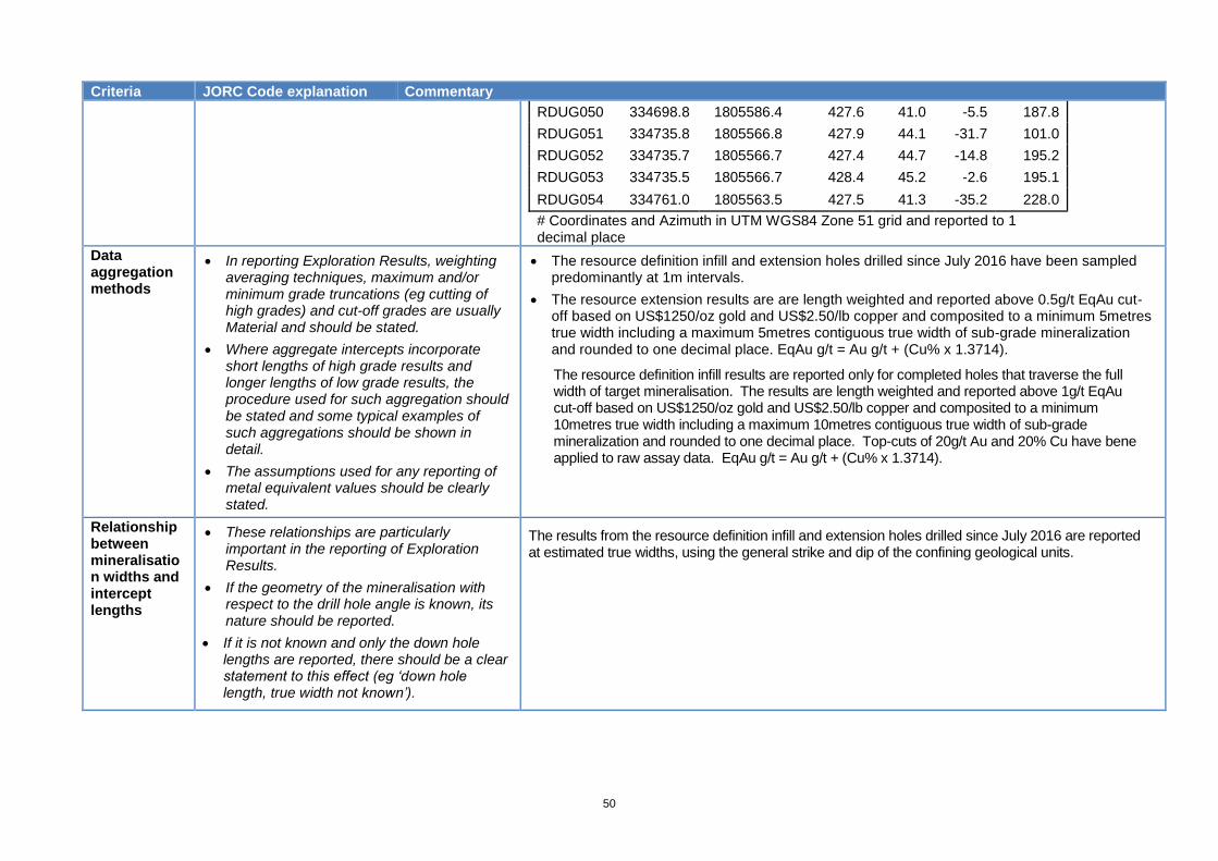
50
Criteria JORC Code explanation Commentary
RDUG050 334698.8 1805586.4 427.6 41.0 -5.5 187.8
RDUG051 334735.8 1805566.8 427.9 44.1 -31.7 101.0
RDUG052 334735.7 1805566.7 427.4 44.7 -14.8 195.2
RDUG053 334735.5 1805566.7 428.4 45.2 -2.6 195.1
RDUG054 334761.0 1805563.5 427.5 41.3 -35.2 228.0
# Coordinates and Azimuth in UTM WGS84 Zone 51 grid and reported to 1 decimal place
Data aggregation methods
• In reporting Exploration Results, weighting averaging techniques, maximum and/or minimum grade truncations (eg cutting of high grades) and cut-off grades are usually Material and should be stated.
• Where aggregate intercepts incorporate short lengths of high grade results and longer lengths of low grade results, the procedure used for such aggregation should be stated and some typical examples of such aggregations should be shown in detail.
• The assumptions used for any reporting of metal equivalent values should be clearly stated.
• The resource definition infill and extension holes drilled since July 2016 have been sampled predominantly at 1m intervals.
• The resource extension results are are length weighted and reported above 0.5g/t EqAu cut-off based on US$1250/oz gold and US$2.50/lb copper and composited to a minimum 5metres true width including a maximum 5metres contiguous true width of sub-grade mineralization and rounded to one decimal place. EqAu g/t = Au g/t + (Cu% x 1.3714).
The resource definition infill results are reported only for completed holes that traverse the full width of target mineralisation. The results are length weighted and reported above 1g/t EqAu cut-off based on US$1250/oz gold and US$2.50/lb copper and composited to a minimum 10metres true width including a maximum 10metres contiguous true width of sub-grade mineralization and rounded to one decimal place. Top-cuts of 20g/t Au and 20% Cu have bene applied to raw assay data. EqAu g/t = Au g/t + (Cu% x 1.3714).
Relationship between mineralisation widths and intercept lengths
• These relationships are particularly important in the reporting of Exploration Results.
• If the geometry of the mineralisation with respect to the drill hole angle is known, its nature should be reported.
• If it is not known and only the down hole lengths are reported, there should be a clear statement to this effect (eg ‘down hole length, true width not known’).
The results from the resource definition infill and extension holes drilled since July 2016 are reported at estimated true widths, using the general strike and dip of the confining geological units.

51
Criteria JORC Code explanation Commentary
Diagrams • Appropriate maps and sections (with scales)
and tabulations of intercepts should be included for any significant discovery being reported These should include, but not be limited to a plan view of drill hole collar locations and appropriate sectional views.
Plan Layout of Resource Definition Infill Holes in local grid
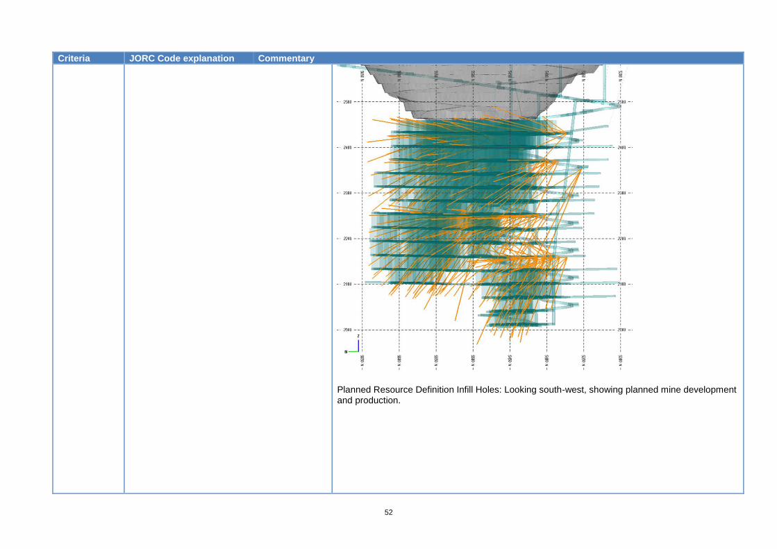
52
Criteria JORC Code explanation Commentary
Planned Resource Definition Infill Holes: Looking south-west, showing planned mine development and production.
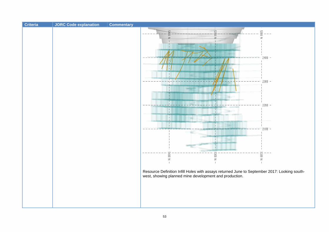
53
Criteria JORC Code explanation Commentary
Resource Definition Infill Holes with assays returned June to September 2017: Looking south-west, showing planned mine development and production.
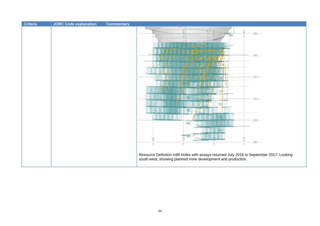
54
Criteria JORC Code explanation Commentary
Resource Definition Infill Holes with assays returned July 2016 to September 2017: Looking south-west, showing planned mine development and production.
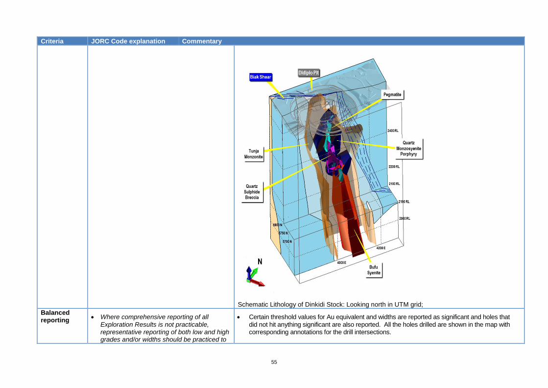
55
Criteria JORC Code explanation Commentary
Schematic Lithology of Dinkidi Stock: Looking north in UTM grid;
Balanced reporting
• Where comprehensive reporting of all Exploration Results is not practicable, representative reporting of both low and high grades and/or widths should be practiced to
• Certain threshold values for Au equivalent and widths are reported as significant and holes that did not hit anything significant are also reported. All the holes drilled are shown in the map with corresponding annotations for the drill intersections.
56
Criteria JORC Code explanation Commentary
avoid misleading reporting of Exploration Results
Other substantive exploration data
Other exploration data, if meaningful and material, should be reported including (but not limited to): geological observations; geophysical survey results; geochemical survey results; bulk samples – size and method of treatment; metallurgical test results; bulk density, groundwater, geotechnical and rock characteristics; potential deleterious or contaminating substances.
• No other data to report.
Further work • The nature and scale of planned further work (eg tests for lateral extensions or depth extensions or large-scale step-out drilling).
• Diagrams clearly highlighting the areas of possible extensions, including the main geological interpretations and future drilling areas, provided this information is not commercially sensitive.
• Resource infill drilling on 40m sections targeting the mineralisation between 2100mRL and 2280mRL will resume in 2018.
Resource definition drilling on 20m sections will continue across the extents of the
underground present and future mine development through to 2020.