Embed Size (px)
Citation preview

Supplementary Information for
Nonlinear optical endomicroscopy for label-free functional histology in vivo
Wenxuan Liang1, Gunnsteinn Hall1, Bernhard Messerschmidt2, Ming-Jun Li3, Xingde Li1*
1Department of Biomedical Engineering, Johns Hopkins University, Baltimore, Maryland 21205, USA2GRINTECH GmbH, Jena, Germany3Science and Technology Division, Corning Incorporated, Corning, New York 14831, USA*Corresponding author. E-mail: [email protected]
This PDF includes:
Supplementary Note S1-S4
Supplementary Figure S1-S8
Supplementary Table S1-S2
1

SUPPLEMNTARY NOTES
S1. System schematic and pulsewidth compensation
We adopted a grating pair and a dual-fiber strategy to manipulate and compensate the pulse
broadening due to both group delay dispersion (GDD) and spectrum narrowing induced by self-phase
modulation (SPM)1, 2 in the optical fibers. As illustrated in Fig. S1, femtosecond pulses from the
Ti:Sapphire laser (Chameleon Vision II, Coherent, Inc., Santa Clara, California, United States), with
an ~150-fs temporal pulse width, were first coupled into a piece of single-mode fiber (SMF, PM780-
HP, Thorlabs, Inc., Newton, New Jersey, United States), and then went through a grating pair for
dispersion compensation. The grating pair (600 lines∙mm-1, Wasatch Photonics, Inc., Durham, North
Carolina, United States) separation was tuned to compensate the total GDD in the SMF (~25 cm long)
and the customized DCF (~75 cm long). We found that that such dual-fiber configuration offered a
convenient way to both compensate dispersion and minimize SPM. And phantom experiments
demonstrated that such dual-fiber strategy could boost the two-photon excitation efficiency by at least
2X compared with the conventional single-fiber setup (manuscript in preparation).
The chirped excitation laser pulses were then launched into the DCF core and delivered to the
sample placed at the distal end of the endomicroscope. Emission photons, once epi-collected through
the achromatic miniature objective into the DCF inner clad, were guided back to the proximal end of
endomicroscope, where they were first separated from the excitation light by a long-pass dichroic
beamsplitter (FF665-Di02-25x36, Semrock, Inc., Rochester, New York, United States), and then
passed a short-pass optical filter (FF01-680/SP-25, Semrock) to further eliminate residual excitation
photons. The resultant signal photons could be spectrally filtered and detected by a photomultiplier
(PMT, H10771P-40, Hamamatsu Photonics K.K., Hamamatsu City, Shizuoka, Japan), as demonstrated
in Fig. S1. In the circumstances where dual-channel detection is needed (such as simultaneous
recording of NADH and FAD signals for redox ratio imaging), a second dichroic beam-splitter
(FF495-Di03-25x36, Semrock) could be used to further separate the emission photons spectrally
towards two separate PMTs. Appropriate optical filters could be placed in front of each PMT to further
define the spectral detection band. Optical filters used in this study included: 445/20 nm band-pass
2
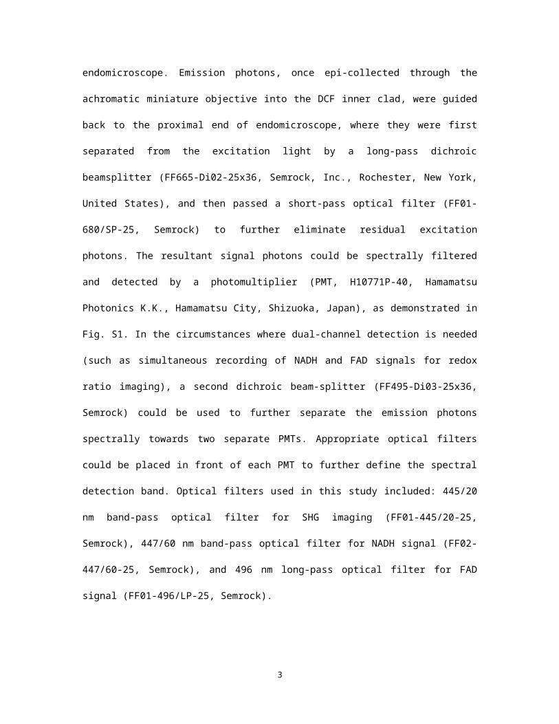
optical filter for SHG imaging (FF01-445/20-25, Semrock), 447/60 nm band-pass optical filter for
NADH signal (FF02-447/60-25, Semrock), and 496 nm long-pass optical filter for FAD signal (FF01-
496/LP-25, Semrock).
S2. Longitudinal focal shift characterization of the miniature objective
We adopted a confocal optical system to measure the longitudinal chromatic aberration of the
miniature objective3. To cover common excitation and emission wavelengths used in two-photon
microscopy, we combined light from three different lasers: one common blue laser (488 nm), one
common green laser (532 nm), and one supercontinuum laser (600-1000 nm, SuperK Extreme, NKT
Photonics, Birkerød, Denmark), as illustrated in Fig. S2. The combined light was coupled into one
input port (Port A) of an ultra-broadband fiber optic coupler (Gould Fiber Optics, Millersville,
Maryland, United States). Light coming out of the output port (Port C) was focused by the miniature
objective onto a silver mirror (with water immersion); then part of the back-reflected got coupled back
into the same single-mode fiber core (which serves as a confocal detection pinhole). Approximately
half of the collected back-reflected photons would exit another input port (Port B) and its spectrum
was measured by a spectrometer (BLUE-Wave VIS-25, StellarNet, Inc., Tampa, Florida, United
States). By scanning the mirror reflector longitudinally through the beam waist, a series of spectra of
the back-reflected light were recorded. From the stack of spectrum data, for each given wavelength of
interest, the reflector displacement corresponding to the peak back-reflection intensity was identified
and deemed as the optimal focal position (or sample-side working distance) for that wavelength.
This measurement method features three major advantages: 1) the usage of optical fiber mimics
exactly the actual application conditions of the miniature objective in the endomicroscope, which is
designed to focus divergent laser beam from the single-mode fiber core; 2) the confocality relationship
between the fiber-side focus (i.e. the fiber core in close vicinity of the fiber end surface) and the
sample-side focus of the miniature objective ensures efficient rejection of other wavelengths whose
focal planes fall farther away from the mirror surface, therefore guaranteeing sensitive and accurate
focal shift measurement; and 3) with the intensity variation of multiple wavelengths measured and
3

recorded simultaneously, only a single mechanical scan of the reflector position is sufficient,
eliminating the need for position calibration between otherwise repeated mechanical scans.
S3. Collection efficiency simulation with the given inner-clad diameter and focal shift
The simulation framework for the endomicroscopy photon propagation has been described in detail
previously4. In essence, fluorescence photons were assumed to be generated inside the tissue at a
specified depth and distributed isotropically. Photon propagation inside scattering tissue was simulated
using the Monte Carlo Multilayered (MCML) approach5, where a water-immersion layer was placed
above the tissue layer. Photons exited the tissue surface with a direction vector v and position p, and
then passed through ray tracing calculations to evaluate whether they would be collected by the inner-
clad of the DCF. We studied the influence of DCF inner-clad diameter and the miniature objective
lens’ chromatic aberrations on the overall collection efficiency of two-photon emission from a tissue
phantom with a scattering mean free path of 92 µm (similar to tissue scattering property)6, and the
wavelength of emission (fluorescence) photons was assumed to be 500 nm.
As shown in Fig. S3, both the enlarged inner-clad diameter and the reduced focal shift of the
miniature objective are beneficial for collecting more scattered photons. Regarding the specific tissue
phantom considered here, our endomicroscope design with a DCF inner clad diameter of 185 µm and
a sample-side focal shift Δf = 10 µm (orange diamond in Fig. S3) can enhance the signal collection
efficiency by ~2.5~2.8X, when compared with the combination of a state-of-the-art GRIN objective
with a focal shift of Δf = 30 µm (GT-MO-080-018-810, GRINTECH GmbH, Jena, Germany) and a
commercial DCF (Nufern 5/130, NuFern, Inc., East Granby, Connecticut, United States) with an
inner-clad diameter of 130 µm (orange circle in Fig. S3).
S4. Redox ratio validation
To validate the measurements of the optical redox ratio (defined as FAD emission/(FAD emission +
NADH emission)), we calibrated our two-photon endomicroscope using NADH and FAD solutions.
Stock solutions (sealed from air) were made by disolving NADH (catalog number N8129, Sigma-
Aldrich Corporation, St. Louis, Missouri, United States) or FAD power (catalog number F6625,
4

Sigma-Aldrich Corporation) in 1 mM Tris-HCl buffer with pH = 8.5. Then via serial dilution, standard
solutions of various concentrations were prepared for NADH (in ~0.1-3.2 mM range) and for FAD (in
~0.1-1.6 mM range).
First, the responses of our two-photon endomicroscope with dual-channel detection to these
standard NADH or FAD solutions were measured and plotted in the Fig. S7. The fluorescence
intensities were observed to scale linearly with the corresponding NADH or FAD concentrations.
Then the mixuture solutions were prepared with the FAD/NADH concentration ratio varying from
1/8 to 2/1 (or equivalently, the FAD concentration fraction varied from 1/9 to 2/3). Such ratio range
was selected based on the knowledge that typical cellular NADH concentration was estimated to be in
the ~100-400 μM range7-10 and FAD concentration in the ~10-150 μM range11-14. The NADH and FAD
fluorescence emission rates were measured from these mixture solutions, and then the optical redox
ratio, was calculated and plotted against the FAD concentration fraction in the solutions. As shown in
the Fig. S8, the optical redox ratio increases monotonically with the fraction of FAD. It is also noted
that the correlation of the measured optical redox ratio with the input FAD concentation fraction is
nonlinear, which could be caused by several factors including the difference between NADH and FAD
in two-photon action cross-section15 and system detection efficiency (e.g. spectra cut-off by optical
filters used for fluorescence detection), and potential cross-quenching of NADH fluorescence by
FAD16, 17 (which can happen both in solutions and in biological tissues).
Based on the above calibration curve, the optical redox ratio of ~0.9 we measured from the kidney
ischemia-reperfusion model (see Fig. 5 in main text) corresponds to a free FAD concentration fraction
of ~0.30. Factoring in the difference in two-photon action cross-section between protein-bound FAD
(~0.28×10-50 cm4∙s) and free-in-solution FAD (~0.071×10-50 cm4∙s)15, we can roughly estimate that the
overall FAD concentration fraction in the mouse kidney renal tubular cells ranges from ~0.075 to
~0.30; this aligns well with the previously reported cellular NADH and FAD concentration
estimations as mentioned above.
5

SUPPLEMNTARY FIGURES
Figure S1 | Schematic illustration of the 2PF endomicroscopy system. See Note S1 for detailed
description of the system design. BP: band-pass optical filter. DCF: double-clad fiber. DM: dichroic
mirror. SP: short-pass optical filter. PMT: photomultiplier tube. SMF: single-mode fiber.
Figure S2 | Schematic of the experimental setup for longitudinal focal shift measurement .
Combined broadband light is first coupled into Port A, and then about 50% of the light exits Port C
and gets focused onto the mirror, which is scanned longitudinally through the focal region. Part of the
back-reflected light is coupled back into the single-mode core of Port C (which serves as a confocal
pinhole), and ~50% of the back-coupled light exits Port B and then is measured by a spectrometer.
CL: coupling lens; DM1: dichroic mirror (FT 580, Carl Zeiss AG, Oberkochen, Germany); DM2:
dichroic mirror (FT 510, Carl Zeiss AG, Oberkochen, Germany); OBJ: miniature objective; M: mirror.
See Note S2 for details about focal shift measurements.
6
Figure S3 | Computed collection efficiency versus DCF inner clad diameter for various sample-
side focal shifts. The simulated tissue phantom used in computing collection efficiency has a
scattering mean free path of 92 µm and a scattering anisotropy (g) of 0.90. The imaging depth in the
tissue phantom was fixed at 100 µm for this simulation study. All collection efficiency values were
normalized with respect to the case of an ideal achromatic objective (corresponding to the black curve,
Δf = 0 μm) used in conjunction with an inner clad of a 300-µm diameter. Corresponding to the orange
diamond is our endomicroscope with a DCF inner clad diameter of 185 μm and a sample-side focal
shift Δf = 10 μm, while the orange circle indicates the combination of a state-of-the-art GRIN
objective (GT-MO-080-018-810, GRINTECH GmbH) and a commercial DCF (Nufern 5/130) with an
inner-clad diameter of 130 μm. See Note S3 for details of the simulation.
7

Figure S4 | Single-frame endomicroscopy 2PF and SHG label-free structural imaging. The
images shown here are the corresponding single-frame version (frame acquisition time ~0.38 second)
of images shown in Fig. 3 of the main text, with the same excitation conditions: ~30 mW at 890 nm
(a-b); ~30 mW (c-d) at 750 nm, and ~40 mW (e-f) at 890 nm. Despite the discernible salt-and-pepper
noise, these single-frame images revealed the vast majority of essential structural details as seen in the
four- (or ten-) frame-averaged versions in Fig. 3. Scale bars, 10 µm.
8

Figure S5 | Endomicroscopy 2PF redox imaging of a mouse kidney ischemia-reperfusion model
in vivo using the 300-µm WD miniature objective. The images shown here were acquired under
similar experimental conditions as those in Fig. 4 of the main text, except that the 300-µm WD
miniature objective was used instead. The essential structural characteristics and functional changes
revealed in Fig. 4 are also manifest here, demonstrating the similar performance of the two miniature
objectives. Top row (a-c): 2PF intensity images from the NADH detection channel (417-477 nm);
middle row (d-f): 2PF intensity images from the FAD detection channel (496-665 nm); bottom row (g-
i): 2PF intensity images color-coded by the measured optical redox ratio, defined as FAD/(FAD +
NADH), where more reddish (greenish) color represents a reduced (increased) redox ratio. The dark
round-to-elliptical spots scattered along the renal tubule wall (marked by dashed squares) correspond
to the nuclei of renal tubular cells, while the arrows (arrowheads) indicate the apical (basolateral) side
of the tubular cells. Each column corresponds to one specific time point: normal (left), 3 min 30 s
post-ischemia (center), and 3 min 05 s post reperfusion (right). All images are averaged over 5 raw
frames acquired with an incident power of ~33 mW at 750 nm, corresponding to an effective frame
9

acquisition time of ~1.9 s. Scale bars, 10 µm.
Figure S6 | Single-frame endomicroscopy 2PF redox imaging of a mouse kidney ischemia-
reperfusion model in vivo. The images shown here were the corresponding single-frame version
(frame acquisition time ~0.38 second) of those images shown in Fig. 4 of the main text. Although
these non-averaged raw images appear noisier, similar structural and functional information are still
discernable. Top row (a-c): 2PF intensity images from the NADH detection channel (417-477 nm);
middle row (d-f): 2PF intensity images from the FAD detection channel (496-665 nm); bottom row (g-
i): 2PF intensity images color-coded by the measured optical redox ratio, defined as FAD/(FAD +
NADH), where more reddish (greenish) color represents to a reduced (increased) redox ratio. The dark
round-to-elliptical spots scattered along the renal tubule wall (shown in dashed squares) correspond to
the nuclei of renal tubular cells, while the arrows (arrowheads) indicate the apical (basolateral) side of
the tubular cells. All images here were acquired with an incident power of ~33 mW at 750 nm. Scale
bars, 10 µm.
10

Figure S7 | Calibration curves of free NADH and free FAD solutions . Blue-diamond data points
represent actual fluorescence emission rate (in million photons/s) measured by our endomicroscope
with NAD detection band of 417-477 nm (a), and FAD detection band of 496-655 nm (b). Red
straight lines in both plots show the linear regression results, with coefficient of determination R 2 =
0.9986 for NADH, and R2 = 0.9971 for FAD.
Figure S8 | Calibration curve of optical redox ratio versus FAD concentration fraction in
solution. The free FAD/NADH concentration ratio is varied from 1/8 to 1/4, 1/2, 1/1, and 2/1 in the
calibration experiment, and the resulted FAD concentration fraction, defined as [FAD]/([FAD]+
[NADH]), is increased from 1/9 to 2/3, as indicated in the x-axis. The optical redox ratio, defined as
FAD emission/(FAD emission + NADH emission), was observed to grow monotonically with the FAD
concentration fraction. This calibration result validates the quantitative accuracy of the optical redox
ratio measured on the mouse kidney ischemia-reperfusion model with our two-photon
endomicroscope (see Note S4 for detailed analysis).
11

SUPPLEMNTARY TABLES
Table S1. In-fiber background reduction by using the customized double-clad fiber (DCF)
Commercial DCFs for
comparison
Emission band of interest (nm)
Total (300-650) SHG (435-455) NADH (417-477) FAD (496-650)
SMM900 40.2 143 101 28.8NuFern 5/130 15.0 18.1 14.1 15.7
Note that within the SHG emission band, the ratio of background suppression is comparatively higher than the total background reduction ratio. The corresponding system sensitivity enhancement ratios can be readily calculated as the square roots of values shown in this table.
Table S2. Comparison of main parameters of the 200- and 300-μm WD miniature objectives
Miniature objectives
Working distance (µm) NA Diameter (mm)Color
correctionFiber-side (in air)
Sample-side (in water)
Fiber-side
Sample-side Optics Overall
Shorter WD 200 200 0.175 0.8 1.0 1.4 Yes
Longer WD 200 300 0.18 0.75 1.8 2.3 Yes
12

REFERENCES
1. Suematsu M, Oda M, Suzuki H, Kaneko H, Watanabe N et al. Intravital and electron microscopic observation of Ito cells in rat hepatic microcirculation. Microvasc Res 1993; 46: 28-42.
2. Clark SW, Ilday FÖ, Wise FW. Fiber delivery of femtosecond pulses from a Ti:sapphire laser. Opt Lett 2001; 26: 1320-1322.
3. Juskaitis R, Wilson T. A method for characterizing longitudinal chromatic aberration of microscope objectives using a confocal optical system. J Microsc 1999; 195 (Pt 1): 17-22.
4. Wu YC, Li XD. Combined influences of chromatic aberration and scattering in depth-resolved two-photon fluorescence endospectroscopy. Biomed Opt Express 2010; 1: 1234-1243.
5. Wang LH, Jacques SL, Zheng LQ. MCML--Monte Carlo modeling of light transport in multi-layered tissues. Comput Methods Programs Biomed 1995; 47: 131-146.
6. Jacques SL. Optical properties of biological tissues: a review. Phys Med Biol 2013; 58: R37-61.
7. Guezennec CY, Lienhard F, Louisy F, Renault G, Tusseau MH et al. In situ NADH laser fluorimetry during muscle contraction in humans. European Journal of Applied Physiology and Occupational Physiology 1991; 63: 36-42.
8. Uppal A, Gupta PK. Measurement of NADH concentration in normal and malignant human tissues from breast and oral cavity. Biotechnol Appl Biochem 2003; 37: 45-50.
9. Yu QR, Heikal AA. Two-photon autofluorescence dynamics imaging reveals sensitivity of intracellular NADH concentration and conformation to cell physiology at the single-cell level. J Photochem Photobiol B 2009; 95: 46-57.
10. Xu HN, Wu BH, Nioka S, Chance B, Li LZ. Quantitative redox scanning of tissue samples using a calibration procedure. Journal of Innovative Optical Health Sciences 2009; 02: 375-385.
11. Kunz WS, Gellerich FN. Quantification of the content of fluorescent flavoproteins in mitochondria from liver, kidney cortex, skeletal muscle, and brain. Biochem Med Metab Biol 1993; 50: 103-110.
12. Ohnishi K, Niimura Y, Yokoyama K, Hidaka M, Masaki H et al. Purification and analysis of a flavoprotein functional as NADH oxidase from Amphibacillus xylanus overexpressed in Escherichia coli. Journal of Biological Chemistry 1994; 269: 31418-31423.
13. Heikal AA. Intracellular coenzymes as natural biomarkers for metabolic activities and mitochondrial anomalies. Biomarkers in Medicine 2010; 4: 241-263.
14. Hühner J, Ingles-Prieto Á, Neusüß C, Lämmerhofer M, Janovjak H. Quantification of riboflavin, flavin mononucleotide, and flavin adenine dinucleotide in mammalian model cells by CE with LED-induced fluorescence detection. Electrophoresis 2015; 36: 518-525.
15. Huang SH, Heikal AA, Webb WW. Two-Photon Fluorescence Spectroscopy and Microscopy of NAD(P)H and Flavoprotein. Biophysical journal 2002; 82: 2811-2825.
16. Hall CL, Kamin H. The purification and some properties of electron transfer flavoprotein and general fatty acyl coenzyme A dehydrogenase from pig liver mitochondria. Journal of Biological Chemistry 1975; 250: 3476-3486.
17. Kierdaszuk B, Malak H, Gryczynski I, Callis P, Lakowicz JR. Fluorescence of reduced nicotinamides using one- and two-photon excitation. Biophys Chem 1996; 62: 1-13.
13