Embed Size (px)
Citation preview
MEDIUM AND HIGH VOLTAGE CAPACITORS, CAPACITOR BANKS AND SYSTEMS
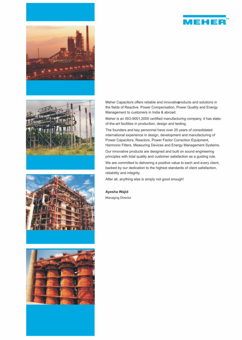
Meher Capacitors offers reliable and innovative products and solutions in
the fields of Reactive Power Compensation, Power Quality and Energy
Management to customers in India & abroad.
Meher is an ISO-9001,2000 certified manufacturing company, it has state-
of-the-art facilities in production, design and testing.
The founders and key personnel have over 25 years of consolidated
international experience in design, development and manufacturing of
Power Capacitors, Reactors, Power Factor Correction Equipment,
Harmonic Filters, Measuring Devices and Energy Management Systems.
Our innovative products are designed and built on sound engineering
principles with total quality and customer satisfaction as a guiding rule.
We are committed to delivering a positive value to each and every client,
backed by our dedication to the highest standards of client satisfaction,
reliability and integrity.
After all, anything else is simply not good enough!
Ayesha Wajid
Managing Director
Medium And High Voltage Capacitor Units
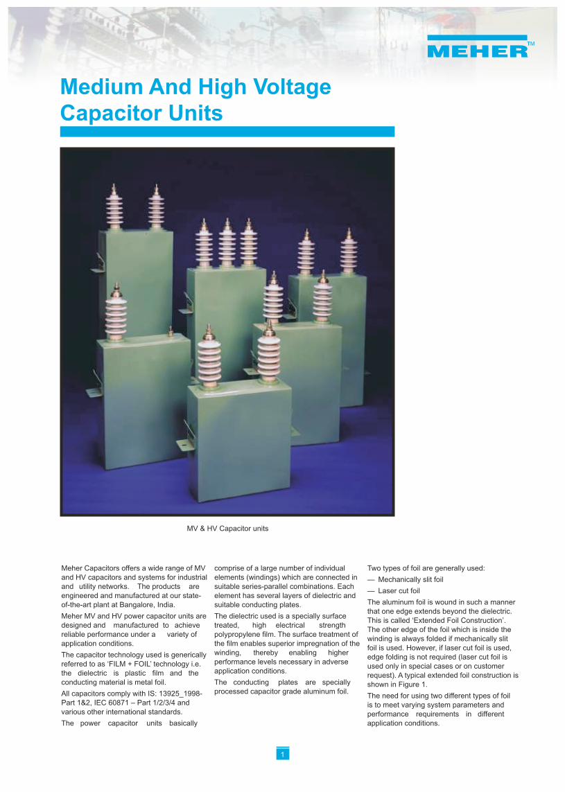
Meher Capacitors offers a wide range of MV comprise of a large number of individual Two types of foil are generally used:and HV capacitors and systems for industrial elements (windings) which are connected in — Mechanically slit foiland utility networks. The products are suitable series-parallel combinations. Each
— Laser cut foilengineered and manufactured at our state- element has several layers of dielectric and
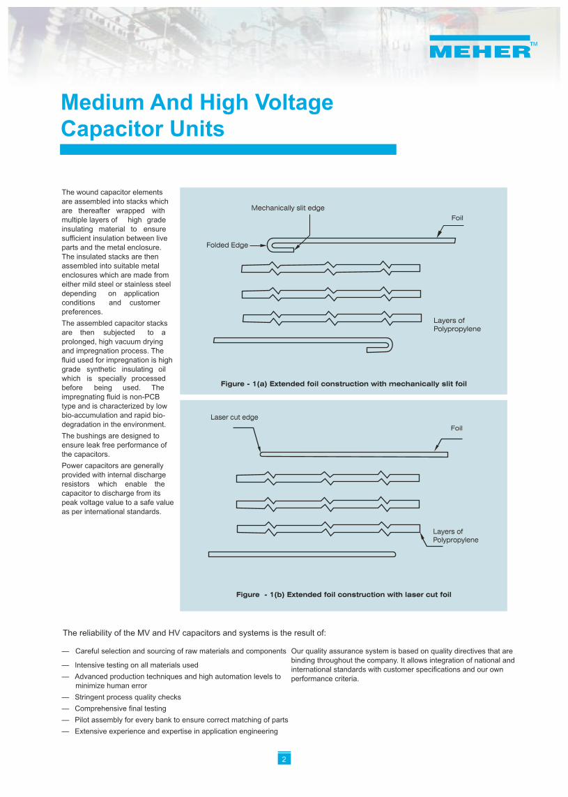
The aluminum foil is wound in such a manner of-the-art plant at Bangalore, India. suitable conducting plates.that one edge extends beyond the dielectric.
Meher MV and HV power capacitor units are The dielectric used is a specially surface This is called ‘Extended Foil Construction’.
designed and manufactured to achieve treated, high electrical strength The other edge of the foil which is inside the
reliable performance under a variety of polypropylene film. The surface treatment of winding is always folded if mechanically slit
application conditions. the film enables superior impregnation of the foil is used. However, if laser cut foil is used,
winding, thereby enabling higher The capacitor technology used is generically edge folding is not required (laser cut foil is performance levels necessary in adverse referred to as ‘FILM + FOIL’ technology i.e. used only in special cases or on customer application conditions.the dielectric is plastic film and the request). A typical extended foil construction is
conducting material is metal foil. The conducting plates are specially shown in Figure 1.processed capacitor grade aluminum foil. All capacitors comply with IS: 13925_1998- The need for using two different types of foil
Part 1&2, IEC 60871 – Part 1/2/3/4 and is to meet varying system parameters and various other international standards. performance requirements in different The power capacitor units basically application conditions.
1
MV & HV Capacitor units
— Careful selection and sourcing of raw materials and components Our quality assurance system is based on quality directives that are binding throughout the company. It allows integration of national and
— Intensive testing on all materials usedinternational standards with customer specifications and our own
— Advanced production techniques and high automation levels to performance criteria.minimize human error
— Stringent process quality checks
— Comprehensive final testing
— Pilot assembly for every bank to ensure correct matching of parts
— Extensive experience and expertise in application engineering
Medium And High Voltage Capacitor Units
The wound capacitor elements are assembled into stacks which are thereafter wrapped with multiple layers of high grade insulating material to ensure sufficient insulation between live parts and the metal enclosure. The insulated stacks are then assembled into suitable metal enclosures which are made from either mild steel or stainless steel depending on application conditions and customer preferences.
The assembled capacitor stacks are then subjected to a prolonged, high vacuum drying and impregnation process. The fluid used for impregnation is high grade synthetic insulating oil which is specially processed before being used. The impregnating fluid is non-PCB type and is characterized by low bio-accumulation and rapid bio-degradation in the environment.
The bushings are designed to ensure leak free performance of the capacitors.
Power capacitors are generally provided with internal discharge resistors which enable the capacitor to discharge from its peak voltage value to a safe value as per international standards.
Figure - 1(a) Extended foil construction with mechanically slit foil
Foil
Mechanically slit edge
Layers of Polypropylene
Folded Edge
Figure - 1(b) Extended foil construction with laser cut foil
Laser cut edge
Foil
Layers of Polypropylene
2
The reliability of the MV and HV capacitors and systems is the result of:
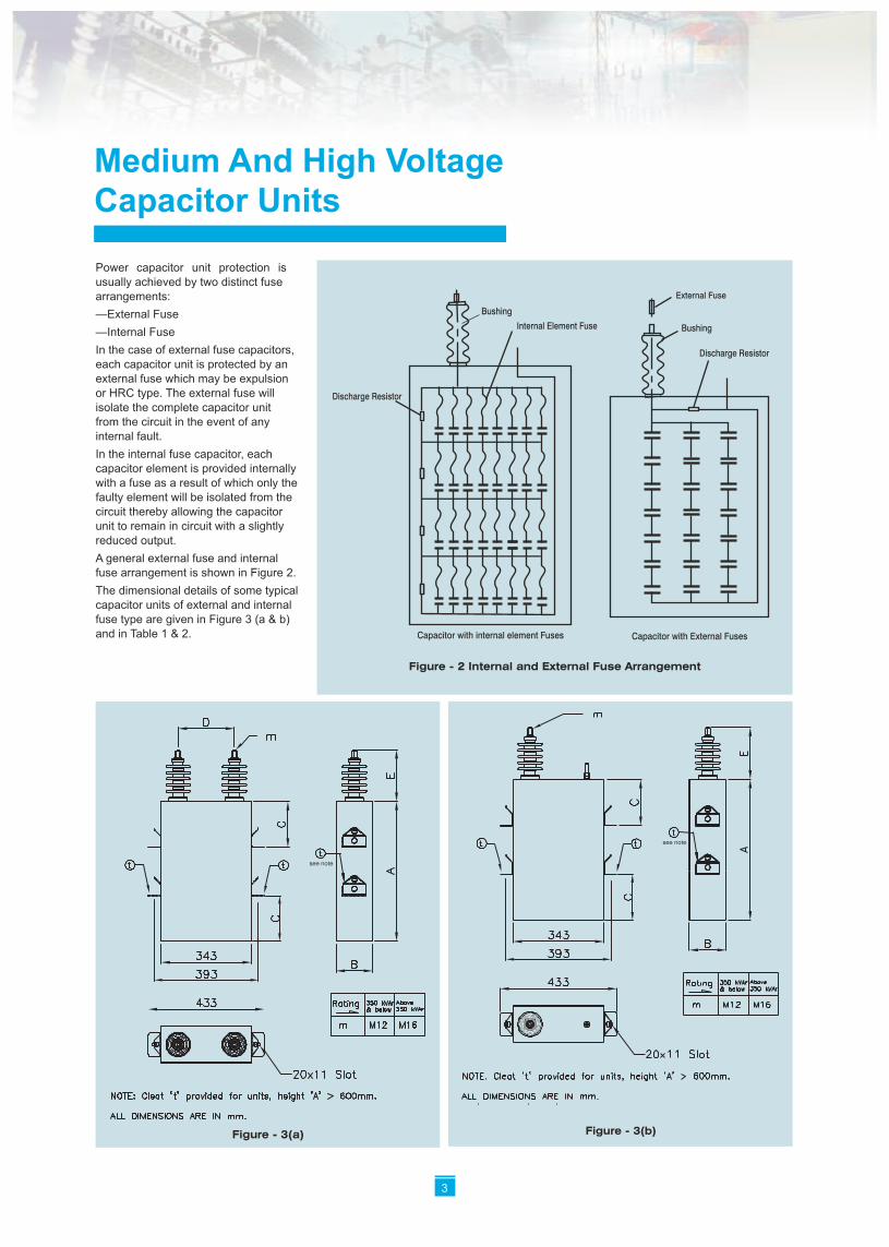
Power capacitor unit protection is usually achieved by two distinct fuse arrangements:
—External Fuse
—Internal Fuse
In the case of external fuse capacitors, each capacitor unit is protected by an external fuse which may be expulsion or HRC type. The external fuse will isolate the complete capacitor unit from the circuit in the event of any internal fault.
In the internal fuse capacitor, each capacitor element is provided internally with a fuse as a result of which only the faulty element will be isolated from the circuit thereby allowing the capacitor unit to remain in circuit with a slightly reduced output.
A general external fuse and internal fuse arrangement is shown in Figure 2.
The dimensional details of some typical capacitor units of external and internal fuse type are given in Figure 3 (a & b) and in Table 1 & 2.
Medium And High Voltage Capacitor Units
Bushing Internal Element Fuse
Discharge Resistor
Capacitor with internal element Fuses
Bushing
External Fuse
Discharge Resistor
Capacitor with External Fuses
Figure - 2 Internal and External Fuse Arrangement
Figure - 3(b)
see note
Figure - 3(a)
see note
3
Medium And High Voltage Capacitor Units
12
7.3 - 12
1.8 - 3.650 75 160 138 191 220 230
3.6 - 7.3 75 160 138 191 220 230
95 160 138 191 220 230
100 1.8 - 3.6 320 2175 138 191 220 230
3.6 - 7.3
75 320 138 191 220 2307.3 - 12
95 320 138 191 220 230
150 1.8 - 3.6 480 3075 138 191 220 230
12 - 22 150 301480 138 191 220
7.3 - 12 95 480 138 191 220 230
200 7.3 - 12 23022019113895 640
301220191138640150 12 - 22
38
250
7.3 - 12
95
960
138 191 220 230
57
301220191138800150 12 - 22
300 95 138 191 220 230
12 - 22 150 960 138 191 220 301
350 7.3 - 12 95 675 178 191 220 230 58
12 - 22 150 675 178 191 220 301
400 7.3 - 12 95 765 178 191 220 230 65
301220191178765150 12 - 22
7.3 - 12 800 48
kV
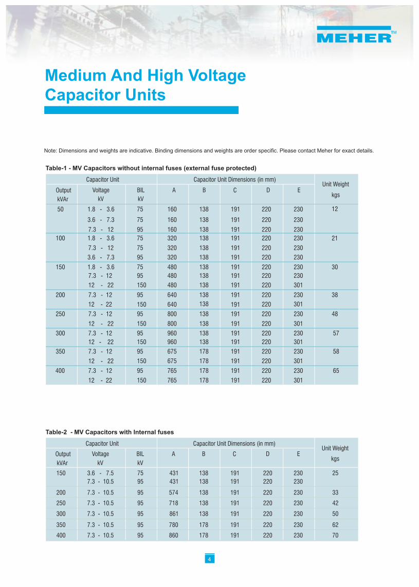
Output Voltage BIL A CB D Ekgs
kV
Unit WeightCapacitor Unit Capacitor Unit Dimensions (in mm)
kVAr
Table-1 - MV Capacitors without internal fuses (external fuse protected)
Note: Dimensions and weights are indicative. Binding dimensions and weights are order specific. Please contact Meher for exact details.
Table-2 - MV Capacitors with Internal fuses
kV
253.6 - 7.5150 75 431 138 191 220 230
7.3 - 10.5 138 191 220 23095
200 574 33138 191 220 230
95 718 138 191 220 230
861 50138 191 220 230
780 178 191 220
Output Voltage BIL A CB D Ekgs
kV
Unit WeightCapacitor Unit
431
250
7.3 - 10.5
7.3 - 10.5
300
350
400
7.3 - 10.5
7.3 - 10.5
7.3 - 10.5
95
95
95
95 860 178 191 220
230
230
42
62
70
Capacitor Unit Dimensions (in mm)
kVAr
4
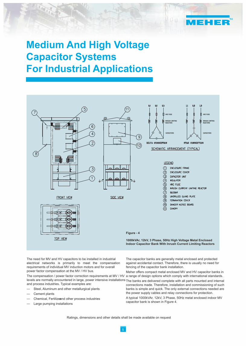
The need for MV and HV capacitors to be installed in industrial The capacitor banks are generally metal enclosed and protected electrical networks is primarily to meet the compensation against accidental contact. Therefore, there is usually no need for requirements of individual MV induction motors and for overall fencing of the capacitor bank installation.power factor compensation at the MV / HV bus. Meher offers compact metal enclosed MV and HV capacitor banks in The compensation / power factor correction requirements at MV / HV a range of design options which comply with international standards.levels are normally encountered in large, power intensive installations The banks are delivered complete with all parts mounted and internal and process industries. Typical examples are: connections made. Therefore, installation and commissioning of such — Steel, Aluminum and other metallurgical plants banks is simple and quick. The only external connections needed are
the power supply cables and relay connections for protection.— Cement plantsA typical 1000kVAr, 12kV, 3 Phase, 50Hz metal enclosed indoor MV — Chemical, Fertilizer and other process industriescapacitor bank is shown in Figure 4.
— Large pumping installations
Medium And High Voltage Capacitor Systems For Industrial Applications
5
Ratings, dimensions and other details shall be made available on request
Figure - 4
1000kVAr, 12kV, 3 Phase, 50Hz High Voltage Metal EnclosedIndoor Capacitor Bank With Inrush Current Limiting Reactors
HRC FUSE
INRUSH LIMITING REACTORS
CAPACITORS
HRC FUSE
INRUSH LIMITINGREACTORS
CAPACITORS
5
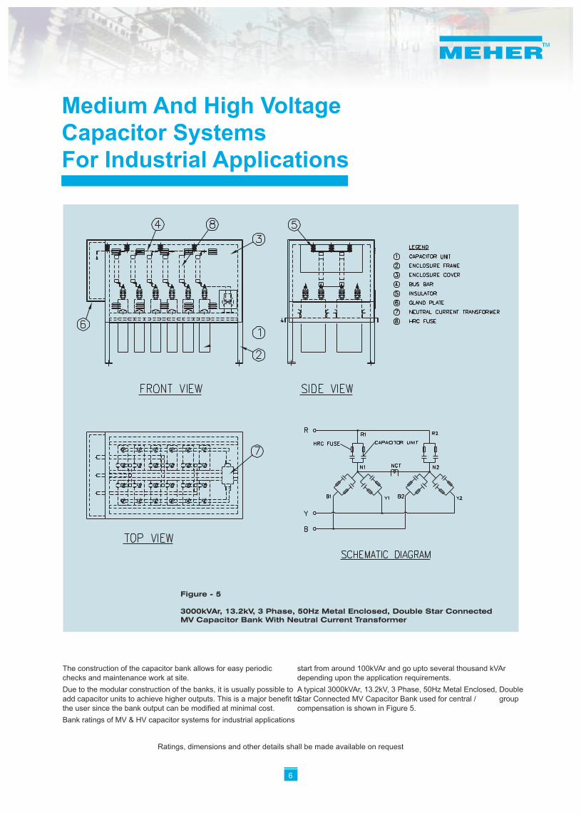
The construction of the capacitor bank allows for easy periodic start from around 100kVAr and go upto several thousand kVAr checks and maintenance work at site. depending upon the application requirements.
Due to the modular construction of the banks, it is usually possible to A typical 3000kVAr, 13.2kV, 3 Phase, 50Hz Metal Enclosed, Double add capacitor units to achieve higher outputs. This is a major benefit to Star Connected MV Capacitor Bank used for central / group the user since the bank output can be modified at minimal cost. compensation is shown in Figure 5.
Bank ratings of MV & HV capacitor systems for industrial applications
Medium And High Voltage Capacitor Systems For Industrial Applications
Ratings, dimensions and other details shall be made available on request
6
Figure - 5
3000kVAr, 13.2kV, 3 Phase, 50Hz Metal Enclosed, Double Star Connected MV Capacitor Bank With Neutral Current Transformer
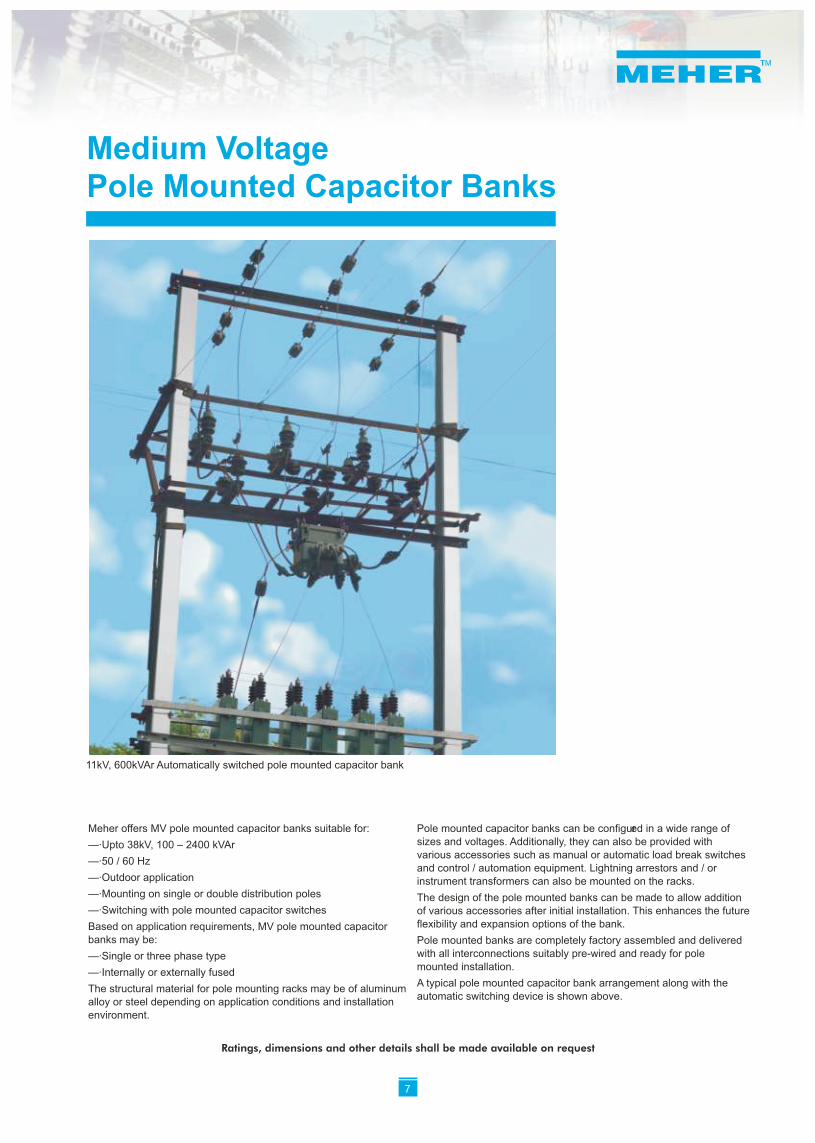
Meher offers MV pole mounted capacitor banks suitable for: Pole mounted capacitor banks can be configured in a wide range of sizes and voltages. Additionally, they can also be provided with —·Upto 38kV, 100 – 2400 kVArvarious accessories such as manual or automatic load break switches
—·50 / 60 Hzand control / automation equipment. Lightning arrestors and / or
—·Outdoor application instrument transformers can also be mounted on the racks.—·Mounting on single or double distribution poles The design of the pole mounted banks can be made to allow addition —·Switching with pole mounted capacitor switches of various accessories after initial installation. This enhances the future
flexibility and expansion options of the bank.Based on application requirements, MV pole mounted capacitor banks may be: Pole mounted banks are completely factory assembled and delivered
with all interconnections suitably pre-wired and ready for pole —·Single or three phase typemounted installation.
—·Internally or externally fusedA typical pole mounted capacitor bank arrangement along with the
The structural material for pole mounting racks may be of aluminum automatic switching device is shown above.
alloy or steel depending on application conditions and installation environment.
Medium Voltage Pole Mounted Capacitor Banks
11kV, 600kVAr Automatically switched pole mounted capacitor bank
Ratings, dimensions and other details shall be made available on request
7
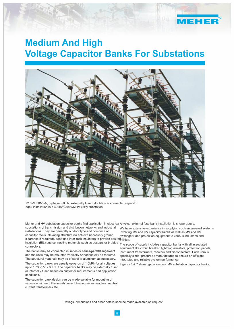
Meher and HV substation capacitor banks find application in electrical A typical external fuse bank installation is shown above.substations of transmission and distribution networks and industrial We have extensive experience in supplying such engineered systems installations. They are generally outdoor type and comprise of involving MV and HV capacitor banks as well as MV and HV capacitor racks, elevating structure (to achieve necessary ground switchgear and protection equipment to various industries and clearance if required), base and inter-rack insulators to provide desired utilities.insulation (BIL) and connecting materials such as busbars or braided
The scope of supply includes capacitor banks with all associated connectors.
equipment like circuit breaker, lightning arrestors, protection panels, The banks may be connected in series or series-parallel arrangement instrument transformers, reactors and disconnectors. Each item is and the units may be mounted vertically or horizontally as required. specially sized, procured / manufactured to ensure an efficient, The structural materials may be of steel or aluminum as necessary. integrated and reliable system performance.The capacitor banks are usually upwards of 1.0MVAr for all voltages Figures 6 & 7 show typical outdoor MV substation capacitor banks.up to 132kV, 50 / 60Hz. The capacitor banks may be externally fused or internally fused based on customer requirements and application conditions.
The capacitor bank design can be made suitable for mounting of various equipment like inrush current limiting series reactors, neutral current transformers etc.
Medium And High Voltage Capacitor Banks For Substations
8
72.5kV, 30MVAr, 3 phase, 50 Hz, externally fused, double star connected capacitor bank installation in a 400kV/220kV/66kV utility substation
Ratings, dimensions and other details shall be made available on request
8
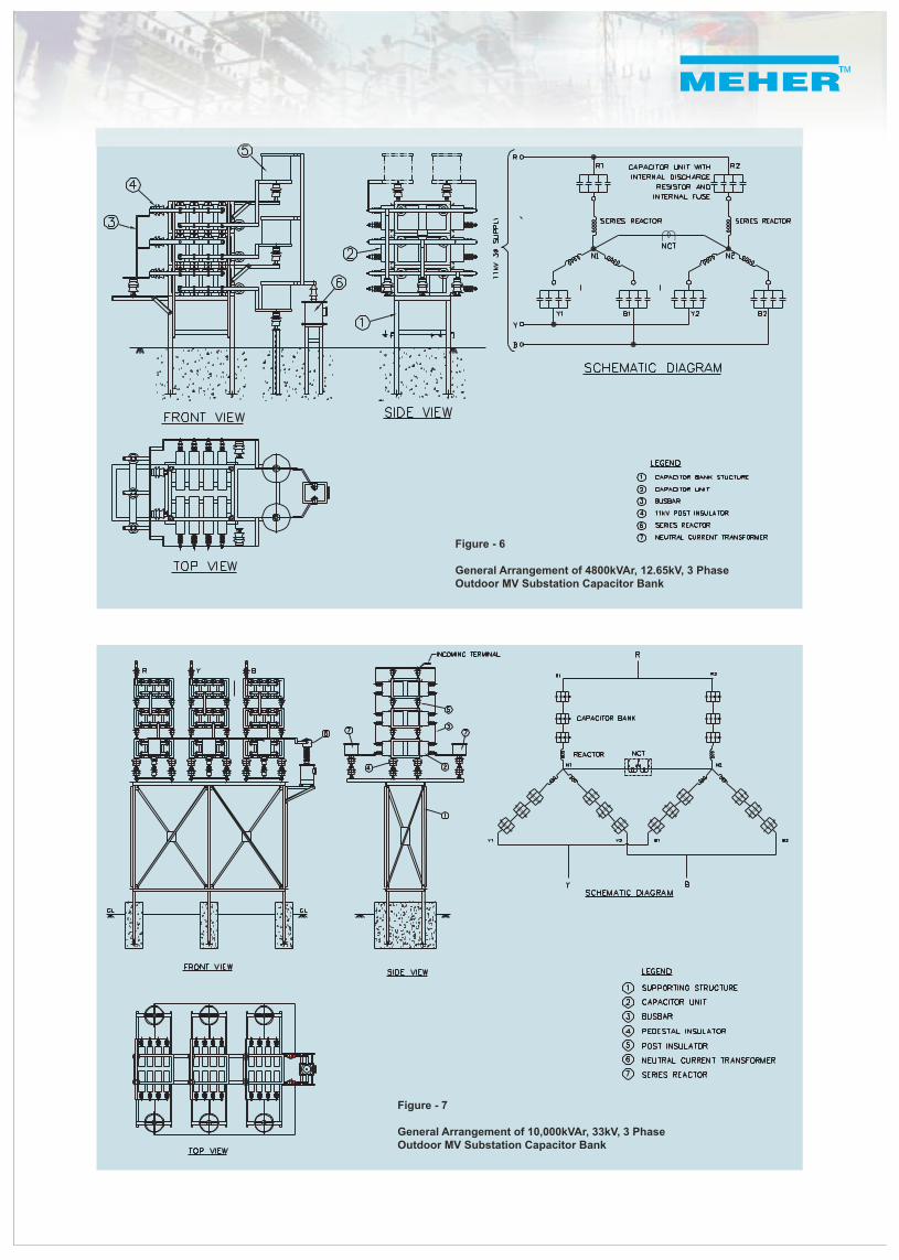
Figure - 6
General Arrangement of 4800kVAr, 12.65kV, 3 Phase Outdoor MV Substation Capacitor Bank
Figure - 7
General Arrangement of 10,000kVAr, 33kV, 3 Phase Outdoor MV Substation Capacitor Bank
Contact your nearest dealer:
© 2006 Meher Capacitors (P) Ltd.,Reproduction, publication and circulation of this catalogue and the information contained therein without Meher Capacitors prior consent is prohibited.
We reserve the right to technical alternations at any time without notice
Purchase orders are subject to the general conditions for the supply of products and services of the electrical and electronics industry recommended by IEEMA (Electrical and Electronic Manufacturers' association) unless otherwise agreed.
Meher Capacitors Pvt. Ltd.,
Corporate Office:
# 52/1, Basappa Road, Shanthinagar, Bangalore-560 027.Tel: 91-80-22225325 Fax: 91-80-22225352
Works:
#16 (K), Attibele Industrial Area, Neralur-562 107, Bangalore Dist.Tel: (080) 7820211, 7820214 Fax: (080) 7820236