Embed Size (px)
Citation preview
MEDIUM ENERGY BEAM TRANSPORT DESIGN UPDATE FOR ESS
I. Bustinduy∗, O. Gonzalez, A. Ghiglino, I. Rodrıguez,J.L. Munoz, A. Zugazaga, F.J. Bermejo
ESS-Bilbao, SpainR. Miyamoto, B. Cheymol, M. Eshraqui, J. Stovall
ESS, Sweden
AbstractThe major challenge of this part of the accelerator is to
keep a high quality beam, with a pulse well defined in time,
a low emittance and a minimized halo, so that the beam
losses downstream the linac be limited and the overall ESS
reliability be maximized. In order to minimize beam loss at
high energy linac, and the consequent activation of compo-
nents, a fast chopping scheme is presented for the medium
energy beam transport section (MEBT). The considered
versatile MEBT is being designed to achieve four main
goals: First, to contain a fast chopper and its correspondent
beam dump, that could serve in the commissioning as well
as in the ramp up phases. Second, to serve as a halo scrap-
ing section by means of various adjustable blades. Third, to
measure the beam phase and profile between the RFQ and
the DTL, along with other beam monitors. And finally, to
match the RFQ output beam characteristics to the DTL in-
put both transversally and longitudinally. For this purpose
a set of ten quadrupoles is used to match the beam char-
acteristics transversally, combined with three 352.2 MHz
buncher cavities, which are used to adjust the beam in or-
der to fulfill the required longitudinal parameters.
INTRODUCTIONAlong the different designs for high-intensity linear
accelerators, the MEBT emerges as one of the critical
stretches through the accelerator in terms of losses, emit-
tance increase and halo formation. With the purpose of
minimizing emittance growth along this section due to the
effects of spatial charge, at least the following two condi-
tions must be satisfied: supplying a solid cross focalization
and avoiding sharp changes in focalization strength. To this
end, a compact quadrupole with a length of 70 mm is being
designed. In addition, some of these quadrupoles, whose
field gradients vary between 9 and 30 T/m, are expected
to incorporate correcting dipoles in order to minimize any
beam misalignments (see Table 1).
LAYOUTThe layout (Fig. 1) is being designed to achieve four
main goals: First, to contain a fast chopper and its cor-
respondent beam dump, that could serve in the commis-
Table 1: MEBT Operation Parameters
Parameter Value
Input Energy 3 MeV (β =0,0798)
Total Current 50 mA
Particle protons (H+)
Number de quadrupoles 10
Min./Max quadrupole gradients 9–30 T/m
Number of buncher cavities 3
Frequency 352.2 MHz
Peak power per cavity 14 kW
Effective Voltage (EoTL) 150 kV
sioning as well as in the ramp up phases. Second, to serve
as a halo scraping section by means of various adjustable
blades. Third, to measure the beam phase and profile be-
tween the RFQ and the DTL, along with other beam moni-
tors. Finally, to match the RFQ output beam characteristics
to the DTL input both transversally and longitudinally. Fig-
ure 3 shows the realistic RFQ output distribution used in the
simulations, the emittance increase along the MEBT, ob-
tained with TRACEWIN, prior to any collimation scheme
is Δεxx′=17.2%, Δεyy′=14.8%, Δεzz′= − 1.5%; keep-
ing the halo parameter <1.4 for all planes (see Fig. 2);
with a negligible 0.05% of cumulative losses along the line.
When the collimation scheme is applied Δεxx′=14.1%,
Δεyy′=10%, Δεzz′=−1.8%, while cumulative losses stay
below an acceptable 1.3%.
The presented layout S0Q10R3C41 constitutes a rela-
tively compact design (∼3600 mm). It comprises a fast
chopper structure, beam dump and provides the separa-
tion for the required diagnostics. Similarly to CERN, J-
PARC and SNS designs, this fast chopper complements to
the LEBT pre-chopper, and will be used to sharpen the
beam edges produced by the slow-chopper during rising
and falling times (∼10 ns). Eliminating thus, the partially
chopped beam that passes through the RFQ [1]. Funda-
mentally, the chopping structure is based on the Linac4 de-
sign. It consists of an electrostatic traveling wave deflector
together with a beam dump for dissipating the sectioned
beam current, with the goal of reducing beam losses that
will occur at higher energies.
10 solenoids, 10 quads, 3 bunchers, 4 collimators
MOP235 Proceedings of HB2012, Beijing, China
ISBN 978-3-95450-118-2
128Cop
yrig
ht(C
)201
2by
the
resp
ectiv
eau
thor
s—C
CB
Y3.
0
Beam Dynamics in High-intensity Linacs
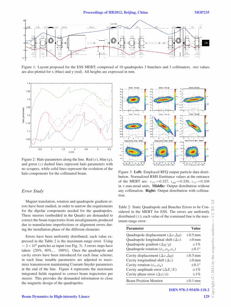
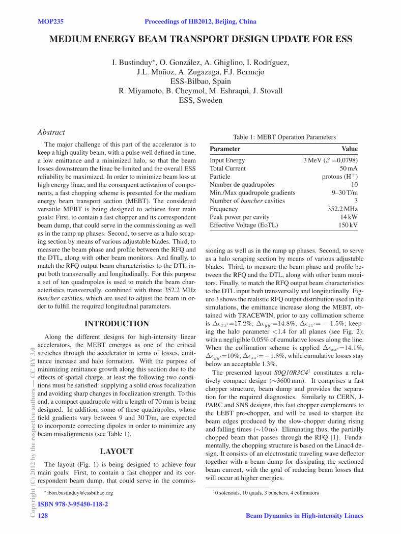
Figure 1: Layout proposed for the ESS MEBT; comprised of 10 quadrupoles 3 bunchers and 3 collimators. rms values
are also plotted for x (blue) and y (red). All heights are expressed in mm.
Figure 2: Halo parameters along the line. Red (x), blue (y),
and green (z) dashed lines represent halo parameters with
no scrapers, while solid lines represent the evolution of the
halo components for the collimated beam.
Error Study
Magnet translation, rotation and quadrupole gradient er-
rors have been studied, in order to narrow the requirements
for the dipolar components needed for the quadrupoles.
These steerers (embedded in the Quads) are demanded to
correct the beam trajectories from misalignments produced
due to manufacture imperfections or alignment errors dur-
ing the installation phase of the different elements.
Errors have been uniformly distributed; each value ex-
pressed in the Table 2 is the maximum range error. Using
∼ 2×10⁵ particles as input (see Fig. 3). 5 errors steps have
taken: [20%, 40%,... 100%]. Once the quadrupole and
cavity errors have been introduced for each linac scheme;
in each linac tunable parameters are adjusted to maxi-
mize transmission maintaining Courant-Snyder parameters
at the end of the line. Figure 4 represents the maximum
integrated fields required to correct beam trajectories per
steerer. This provides the demanded information to close
the magnetic design of the quadrupoles.
Figure 3: Left: Employed RFQ output particle data distri-
bution. Normalized RMS Emittance values at the entrance
of the MEBT are: εxx′=0.227, εyy′=0.230, εzz′=0.338in π.mm.mrad units. Middle: Output distribution without
any collimation. Right: Output distribution with collima-
tion.
Table 2: Static Quadrupole and Buncher Errors to be Con-
sidered in the MEBT for ESS. The errors are uniformly
distributed (±); each value of the command line is the max-
imum range error.
Parameter Value
Quadrupole displacement (Δx,Δy) ±0.5 mm
Quadrupole longitudinal shift (Δz) ±0 mm
Quadrupole gradient (Δg/g) ±1%
Quadrupole rotation (φx,φy ,φz) ±0.1o
Cavity displacement (Δx,Δy) ±0.5 mm
Cavity longitudinal shift (Δz) ±0 mm
Cavity rotation (φx,φy) ±0.1o
Cavity amplitude error (ΔE/E) ±1%
Cavity phase error (Δφ/φ) ±1%
Beam Position Monitor ±0.1 mm
Proceedings of HB2012, Beijing, China MOP235
Beam Dynamics in High-intensity Linacs
ISBN 978-3-95450-118-2
129 Cop
yrig
ht(C
)201
2by
the
resp
ectiv
eau
thor
s—C
CB
Y3.
0
0 10 20 30 40 50 60 700
2
4
6
8
10
# element
|Max
imum
Str
engt
h (G
.m)|
20%40%60%80%100%
Figure 4: Maximum strength (|G.m|) obtained for each
steerer, considering the proposed layout. Results are pre-
sented in steps, going from 20% error, 40%, upto 100%.
Diagnostics
The proposal of ESS beam instrumentation group is to
measure the 6D beam phase space in the MEBT using a
reducing beam power (100μs, 50 mA, 1 Hz Rep. rate or
10μs, 50 mA, 14 Hz Rep. rate ) using a list of diagnostics:
A set of 6 Beam Position Monitors (BPMs); at least two
of those are essential for time-of- flight, three for absolute
energy measurement. a Bunch Shape Monitor (BSM) is
foreseen for bunch length measurements. One Beam Cur-
rent Transformers (BCT) will be installed at the beginning.
The sampling rate of the BCT shall be 10 MHz with a res-
olution of 1% of the nominal beam current. A second one
will be installed in the DTL tank in order to measure the
input current in the DTL. As for the other BCT foreseen
to be installed in the warm linac, the current monitors will
also measure the beam transmission between two monitors
and will be integrated in the Machine Protection System
(MPS). 4 Wire Scanners are also, planned to be installed.
Two of those wire scanners shall be equipped with high dy-
namic range electronic in order to measure the beam trans-
verse halo. Finally for emittance measurements, a Slit-and-
Grid emittance measurement system is scheduled.
Collimation
The use of scrapers before entering DTL tanks is
strongly recommended to avoid emittance growth and halo
development in high-intensity linacs [2]. In our current de-
sign, collimators should be able to scrap the beam in the
both transverse plane at each locations. For this, 4 stepping
motors are needed per locations. The scrapper will be used
during nominal operation, the collimator system has to be
integrated in the interlock system in order to avoid interac-
tion with the beam core, the position of the beam will be
provided by a BPM positioned as close as possible to the
collimator and the movement has to be limited. In addition,
the temperature can be measure in the scrapper and also the
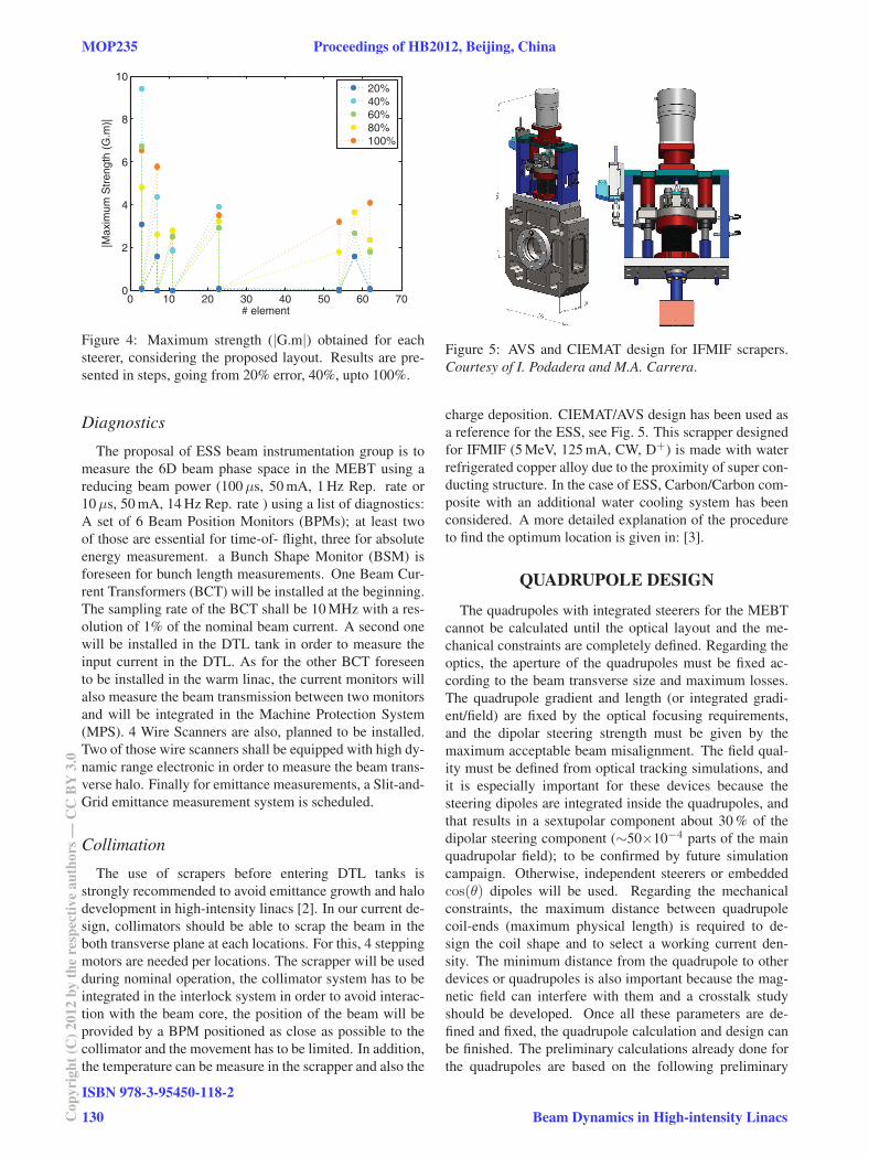
Figure 5: AVS and CIEMAT design for IFMIF scrapers.
Courtesy of I. Podadera and M.A. Carrera.
charge deposition. CIEMAT/AVS design has been used as
a reference for the ESS, see Fig. 5. This scrapper designed
for IFMIF (5 MeV, 125 mA, CW, D+) is made with water
refrigerated copper alloy due to the proximity of super con-
ducting structure. In the case of ESS, Carbon/Carbon com-
posite with an additional water cooling system has been
considered. A more detailed explanation of the procedure
to find the optimum location is given in: [3].
QUADRUPOLE DESIGN
The quadrupoles with integrated steerers for the MEBT
cannot be calculated until the optical layout and the me-
chanical constraints are completely defined. Regarding the
optics, the aperture of the quadrupoles must be fixed ac-
cording to the beam transverse size and maximum losses.
The quadrupole gradient and length (or integrated gradi-
ent/field) are fixed by the optical focusing requirements,
and the dipolar steering strength must be given by the
maximum acceptable beam misalignment. The field qual-
ity must be defined from optical tracking simulations, and
it is especially important for these devices because the
steering dipoles are integrated inside the quadrupoles, and
that results in a sextupolar component about 30 % of the
dipolar steering component (∼50×10−4 parts of the main
quadrupolar field); to be confirmed by future simulation
campaign. Otherwise, independent steerers or embedded
cos(θ) dipoles will be used. Regarding the mechanical
constraints, the maximum distance between quadrupole
coil-ends (maximum physical length) is required to de-
sign the coil shape and to select a working current den-
sity. The minimum distance from the quadrupole to other
devices or quadrupoles is also important because the mag-
netic field can interfere with them and a crosstalk study
should be developed. Once all these parameters are de-
fined and fixed, the quadrupole calculation and design can
be finished. The preliminary calculations already done for
the quadrupoles are based on the following preliminary
MOP235 Proceedings of HB2012, Beijing, China
ISBN 978-3-95450-118-2
130Cop
yrig
ht(C
)201
2by
the
resp
ectiv
eau
thor
s—C
CB
Y3.
0
Beam Dynamics in High-intensity Linacs
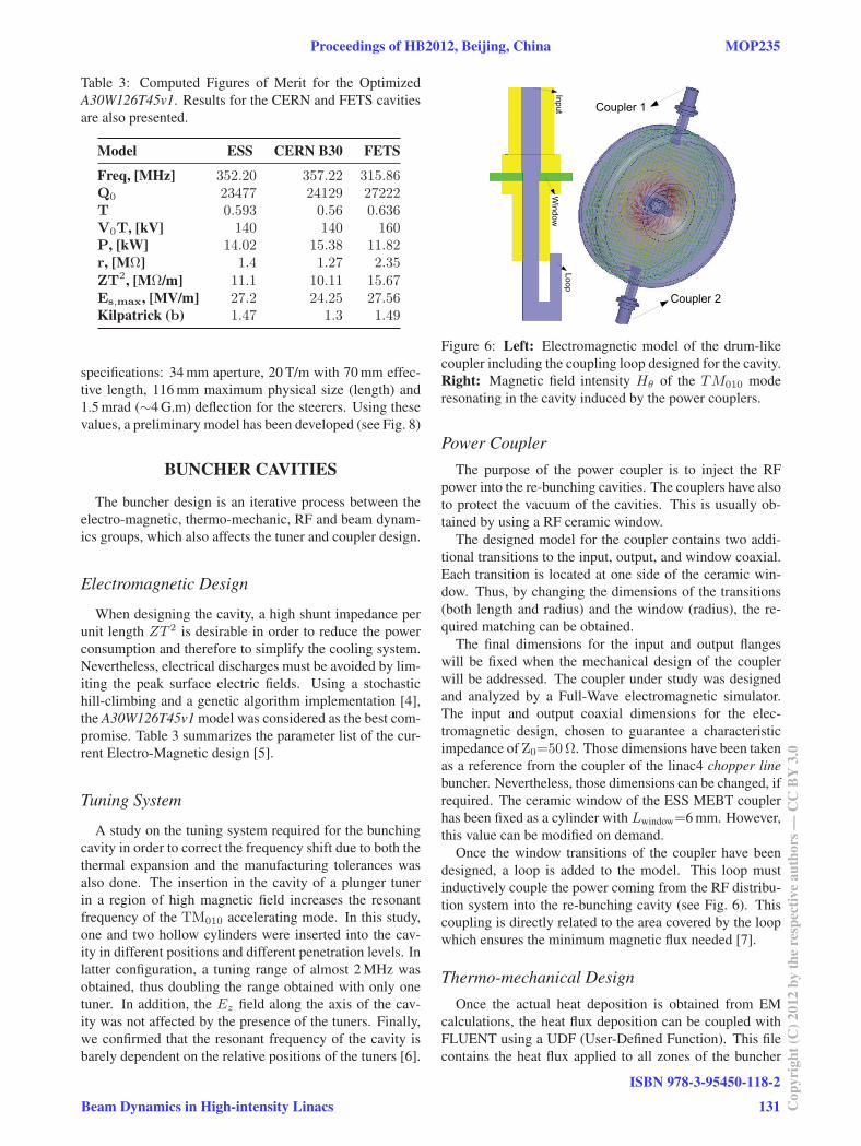
Table 3: Computed Figures of Merit for the Optimized
A30W126T45v1. Results for the CERN and FETS cavities
are also presented.
Model ESS CERN B30 FETS
Freq, [MHz] 352.20 357.22 315.86Q0 23477 24129 27222T 0.593 0.56 0.636V0T, [kV] 140 140 160P, [kW] 14.02 15.38 11.82r, [MΩ] 1.4 1.27 2.35
ZT2, [MΩ/m] 11.1 10.11 15.67Es,max, [MV/m] 27.2 24.25 27.56Kilpatrick (b) 1.47 1.3 1.49
specifications: 34 mm aperture, 20 T/m with 70 mm effec-
tive length, 116 mm maximum physical size (length) and
1.5 mrad (∼4 G.m) deflection for the steerers. Using these
values, a preliminary model has been developed (see Fig. 8)
BUNCHER CAVITIES
The buncher design is an iterative process between the
electro-magnetic, thermo-mechanic, RF and beam dynam-
ics groups, which also affects the tuner and coupler design.
Electromagnetic Design
When designing the cavity, a high shunt impedance per
unit length ZT 2 is desirable in order to reduce the power
consumption and therefore to simplify the cooling system.
Nevertheless, electrical discharges must be avoided by lim-
iting the peak surface electric fields. Using a stochastic
hill-climbing and a genetic algorithm implementation [4],
the A30W126T45v1 model was considered as the best com-
promise. Table 3 summarizes the parameter list of the cur-
rent Electro-Magnetic design [5].
Tuning System
A study on the tuning system required for the bunching
cavity in order to correct the frequency shift due to both the
thermal expansion and the manufacturing tolerances was
also done. The insertion in the cavity of a plunger tuner
in a region of high magnetic field increases the resonant
frequency of the TM010 accelerating mode. In this study,
one and two hollow cylinders were inserted into the cav-
ity in different positions and different penetration levels. In
latter configuration, a tuning range of almost 2 MHz was
obtained, thus doubling the range obtained with only one
tuner. In addition, the Ez field along the axis of the cav-
ity was not affected by the presence of the tuners. Finally,
we confirmed that the resonant frequency of the cavity is
barely dependent on the relative positions of the tuners [6].
Figure 6: Left: Electromagnetic model of the drum-like
coupler including the coupling loop designed for the cavity.
Right: Magnetic field intensity Hθ of the TM010 mode
resonating in the cavity induced by the power couplers.
Power CouplerThe purpose of the power coupler is to inject the RF
power into the re-bunching cavities. The couplers have also
to protect the vacuum of the cavities. This is usually ob-
tained by using a RF ceramic window.
The designed model for the coupler contains two addi-
tional transitions to the input, output, and window coaxial.
Each transition is located at one side of the ceramic win-
dow. Thus, by changing the dimensions of the transitions
(both length and radius) and the window (radius), the re-
quired matching can be obtained.
The final dimensions for the input and output flanges
will be fixed when the mechanical design of the coupler
will be addressed. The coupler under study was designed
and analyzed by a Full-Wave electromagnetic simulator.
The input and output coaxial dimensions for the elec-
tromagnetic design, chosen to guarantee a characteristic
impedance of Z0=50Ω. Those dimensions have been taken
as a reference from the coupler of the linac4 chopper linebuncher. Nevertheless, those dimensions can be changed, if
required. The ceramic window of the ESS MEBT coupler
has been fixed as a cylinder with Lwindow=6 mm. However,
this value can be modified on demand.
Once the window transitions of the coupler have been
designed, a loop is added to the model. This loop must
inductively couple the power coming from the RF distribu-
tion system into the re-bunching cavity (see Fig. 6). This
coupling is directly related to the area covered by the loop
which ensures the minimum magnetic flux needed [7].
Thermo-mechanical DesignOnce the actual heat deposition is obtained from EM
calculations, the heat flux deposition can be coupled with
FLUENT using a UDF (User-Defined Function). This file
contains the heat flux applied to all zones of the buncher
Proceedings of HB2012, Beijing, China MOP235
Beam Dynamics in High-intensity Linacs
ISBN 978-3-95450-118-2
131 Cop
yrig
ht(C
)201
2by
the
resp
ectiv
eau
thor
s—C
CB
Y3.
0
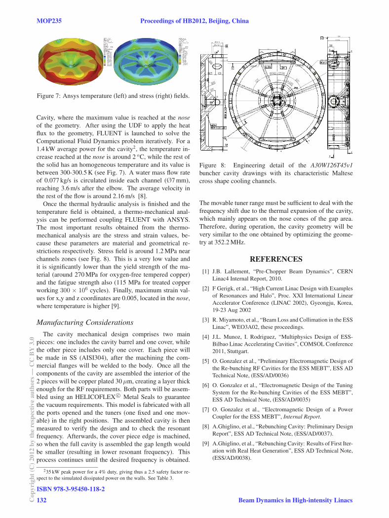
Figure 7: Ansys temperature (left) and stress (right) fields.
Cavity, where the maximum value is reached at the noseof the geometry. After using the UDF to apply the heat
flux to the geometry, FLUENT is launched to solve the
Computational Fluid Dynamics problem iteratively. For a
1.4 kW average power for the cavity2, the temperature in-
crease reached at the nose is around 2 oC, while the rest of
the solid has an homogeneous temperature and its value is
between 300-300.5 K (see Fig. 7). A water mass flow rate
of 0.077 kg/s is circulated inside each channel (Ø7 mm),
reaching 3.6 m/s after the elbow. The average velocity in
the rest of the flow is around 2.16 m/s [8].
Once the thermal hydraulic analysis is finished and the
temperature field is obtained, a thermo-mechanical anal-
ysis can be performed coupling FLUENT with ANSYS.
The most important results obtained from the thermo-
mechanical analysis are the stress and strain values, be-
cause these parameters are material and geometrical re-
strictions respectively. Stress field is around 1.2 MPa near
channels zones (see Fig. 8). This is a very low value and
it is significantly lower than the yield strength of the ma-
terial (around 270 MPa for oxygen-free tempered copper)
and the fatigue strength also (115 MPa for treated copper
working 300 × 106 cycles). Finally, maximum strain val-
ues for x,y and z coordinates are 0.005, located in the nose,
where temperature is higher [9].
Manufacturing ConsiderationsThe cavity mechanical design comprises two main
pieces: one includes the cavity barrel and one cover, while
the other piece includes only one cover. Each piece will
be made in SS (AISI304), after the machining the com-
mercial flanges will be welded to the body. Once all the
components of the cavity are assembled the interior of the
2 pieces will be copper plated 30μm, creating a layer thick
enough for the RF requirements. Both parts will be assem-
bled using an HELICOFLEX c© Metal Seals to guarantee
the vacuum requirements. This model is fabricated with all
the ports opened and the tuners (one fixed and one mov-
able) in the right positions. The assembled cavity is then
measured to verify the design and to check the resonant
frequency. Afterwards, the cover piece edge is machined,
so when the full cavity is assembled the gap length would
be smaller (resulting in lower resonant frequency). This
process continues until the desired frequency is obtained.
235 kW peak power for a 4% duty, giving thus a 2.5 safety factor re-
spect to the simulated dissipated power on the walls. See Table 3.
Figure 8: Engineering detail of the A30W126T45v1buncher cavity drawings with its characteristic Maltese
cross shape cooling channels.
The movable tuner range must be sufficient to deal with the
frequency shift due to the thermal expansion of the cavity,
which mainly appears on the nose cones of the gap area.
Therefore, during operation, the cavity geometry will be
very similar to the one obtained by optimizing the geome-
try at 352.2 MHz.
REFERENCES[1] J.B. Lallement, “Pre-Chopper Beam Dynamics”, CERN
Linac4 Internal Report, 2010.
[2] F Gerigk, et al., “High Current Linac Design with Examples
of Resonances and Halo”, Proc. XXI International Linear
Accelerator Conference (LINAC 2002), Gyeongju, Korea,
19-23 Aug 2002
[3] R. Miyamoto, et al., “Beam Loss and Collimation in the ESS
Linac”, WEO3A02, these proceedings.
[4] J.L. Munoz, I. Rodriguez, “Multiphysics Design of ESS-
Bilbao Linac Accelerating Cavities”, COMSOL Conference
2011, Stuttgart.
[5] O. Gonzalez et al., “Preliminary Electromagnetic Design of
the Re-bunching RF Cavities for the ESS MEBT”, ESS AD
Technical Note, (ESS/AD/0036)
[6] O. Gonzalez et al., “Electromagnetic Design of the Tuning
System for the Re-bunching Cavities of the ESS MEBT”,
ESS AD Technical Note, (ESS/AD/0035)
[7] O. Gonzalez et al., “Electromagnetic Design of a Power
Coupler for the ESS MEBT”, Internal Report.
[8] A.Ghiglino, et al., “Rebunching Cavity: Preliminary Design
Report”, ESS AD Technical Note, (ESS/AD/0037).
[9] A.Ghiglino, et al., “Rebunching Cavity: Results of First Iter-
ation with Real Heat Generation”, ESS AD Technical Note,
(ESS/AD/0038).
MOP235 Proceedings of HB2012, Beijing, China
ISBN 978-3-95450-118-2
132Cop
yrig
ht(C
)201
2by
the
resp
ectiv
eau
thor
s—C
CB
Y3.
0
Beam Dynamics in High-intensity Linacs