Embed Size (px)
Citation preview
Medium Voltage Distribution
PI 100 up to 24 kVAir-insulated circuit-breaker switchgear for primary distribution
System configuration

Delivery conditionsThe General Conditions of Delivery as amended shall apply.
IllustrationsThe illustrations are not binding.

3PI 100 E
PI 100 Content
■ Introduction ......................................................................................................... 4 □ General description ........................................................................................ 4 □ Features ......................................................................................................... 5
■ Mechanical Design ............................................................................................. 6 □ 24 KV PI in detail with HVX ........................................................................... 6 □ Switchgear panel ............................................................................................ 7 □ Corrosion protection ....................................................................................... 8 □ Low-voltage cabinet ....................................................................................... 8 □ Secondary lines .............................................................................................. 8 □ Cable connection area ................................................................................... 9 □ Current transformers ...................................................................................... 9 □ Voltage transformers ...................................................................................... 9 □ Insulating protection plate .............................................................................. 9 □ Interlocking and coding .................................................................................. 9 □ Auxiliary switches ......................................................................................... 11 □ Voltage testing systems (optional) ............................................................... 11 □ Availability .................................................................................................... 13
■ Environmentally compatible design ............................................................... 14
■ Quality assurance ............................................................................................. 15
■ Standards ......................................................................................................... .16 □ Regulations, provisions and standards ........................................................ 16 □ Operator safety and classification ................................................................ 17 □ Internal faults causing internal arcs ............................................................. 18 □ Installation of switchgear units with IAC qualification .................................. 19 □ Internal arc classification .............................................................................. 19
■ Technical Data .................................................................................................. 21 □ Performance characteristics of PI 100 ......................................................... 21
■ Electrical supplementary modules ................................................................. 23 □ Power consumption and tripping ranges of the releases for LTS, E ........... 23 □ Motor drive ................................................................................................... 24 □ Shunt opening release ................................................................................. 24 □ Panel variants 12 kv / 24 kv ......................................................................... 25
■ Range of products ............................................................................................ 25 □ Range of products ........................................................................................ 25 □ Function codes ............................................................................................. 26
■ Design data ....................................................................................................... 27 □ Dimentions and weights ............................................................................... 27 □ Installation of the switchgear panels ............................................................ 33 □ End plate ...................................................................................................... 33 □ Space requirements ..................................................................................... 33 □ Floor openings ............................................................................................. 34
■ Shipping instructions ....................................................................................... 37 □ Transporting the Panels ............................................................................... 37
■ Request for quotation/Options PI100 ............................................................. 40

4 PI 100 E
PI 100
The PI switchgear is based on a modular single-busbar system with truck-type HVX circuit-breaker. PI supplementary panels with fixed switch disconnectors L-TRI or vacuum contactors (up to 7.2 kV) and billing metering panels complete the range. PI can be completed with the switch disconnector panels PN. The switchgear panels feature a functional front design, simple operation and a long, maintenance-free service life. PI has been designed for a high degree of functionality, straightforward planning and configuration, as well as low investment and operating costs. Existing switchgear can generally be extended on both sides of the system.Due to the modular design of the switchgear assembly, individual panels can be exchanged.By inserting an insulating protection plate whilst the panel door remains closed, the panels are easily and independently accessible for checking purposes, inspections and assembly work with the busbars still energized. The design and the equipment variants offer an economically efficient adaptation to the requirements of the operating company.
General descriptionThe air-insulated circuit-breaker switchgear units PI with
■ rated voltages up to 24 kV ■ rated currents up to 1250 A ■ rated peak withstand currents up to 63 kA ■ rated short-time currents up to 25 kA 1s are primarily used for application in □ switchgear of power supply companies □ industry and □ infrastructure.
Introduction
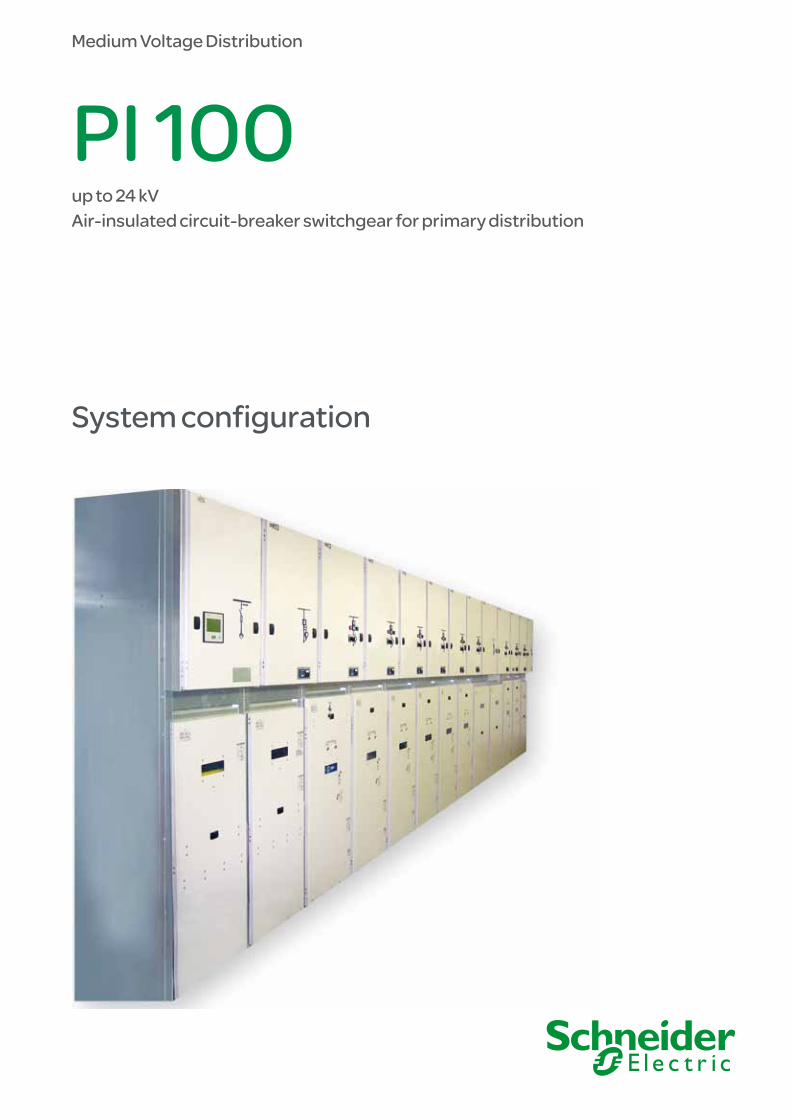
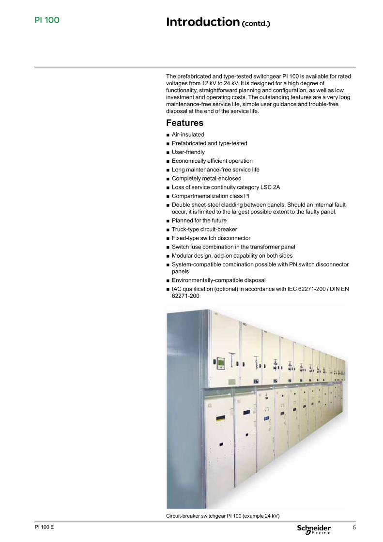
Circuit-breaker switchgear PI 100 (example 24 kV)
PI in detail
5PI 100 E
PI 100 Introduction (contd.)
The prefabricated and type-tested switchgear PI 100 is available for rated voltages from 12 kV to 24 kV. It is designed for a high degree of functionality, straightforward planning and configuration, as well as low investment and operating costs. The outstanding features are a very long maintenance-free service life, simple user guidance and trouble-free disposal at the end of the service life.
Features ■ Air-insulated ■ Prefabricated and type-tested ■ User-friendly ■ Economically efficient operation ■ Long maintenance-free service life ■ Completely metal-enclosed ■ Loss of service continuity category LSC 2A ■ Compartmentalization class PI ■ Double sheet-steel cladding between panels. Should an internal fault occur, it is limited to the largest possible extent to the faulty panel.
■ Planned for the future ■ Truck-type circuit-breaker ■ Fixed-type switch disconnector ■ Switch fuse combination in the transformer panel ■ Modular design, add-on capability on both sides ■ System-compatible combination possible with PN switch disconnector panels
■ Environmentally-compatible disposal ■ IAC qualification (optional) in accordance with IEC 62271-200 / DIN EN 62271-200
Circuit-breaker switchgear PI 100 (example 24 kV)

6 PI 100 E
PI 100 Mechanical design
1
5
2
6
4
15
12
143 4
16
16
7
10
91113
8
1 Low-voltage cabinet2 Mechanical control panel on vacuum circuit-breaker3 Lifting door to circuit-breaker compartment4 Racking device5 Voltage detection system (optional)6 Earthing switch drive mechanism and display7 Busbar system8 HVX vacuum circuit-breaker9 Outgoing earthing switch10 Current transformer11 Cable boxes12 Low-voltage plug-and-socket connector13 Base plate (optional)14 Mechanical circuit-breaker actuation with the panel door closed15 Multiple interlocking of lifting door16 Opening and track for add-in board of insulating material
24 KV PI in detail with HVX

7PI 100 E
PI 100
Switchgear panelThe air-insulated panel PI features metal covers made of hot-galvanized, profiled sheet steel on all sides and is built as a riveted composite structure. Due to the closed design - including the sides - the assembly of the panels creates configured switchgear. The double sheet-metal cladding with an additional air gap of 8 mm between the individual panels ensures a very high degree of operational reliability.
This advantage is of especial significance with regard to the high degree of flexibility and a quick recovery in the improbable event of an internal arc, as the panels can be dismantled from and remounted into the switchgear assembly easily.
The panel door is a userfriendly lifting door. The door hinges can be mounted on the left or right side. Subsequent retrofitting is quick and simple.
Due to the multiple interlocking on both sides of the panel and due to additional overlapping of the door at the top and bottom of the panel, a high degree of mechanical stability is achieved, ensuring maximum operator safety in the event of an internal fault.
The busbar sections are spliced from panel to panel and are held by a bushing plate with bushings.
Final assembly, panels PI
Door with 36 closing points Multiple interlocking with panel door
HVX on trolley User-friendly lifting operation Busbar bushing (double sheet-steel cladding)
Mechanical design (contd.)

8 PI 100 E
PI 100
Corrosion protectionEspecially pre-treated hotgalvanized sheet-steel plates ensure optimum protection against corrosion throughout the switchgear‘s entire service life. All the other metal parts have also been treated to prevent corrosion.In addition, the doors are coated, using the RAL 7044 paint. Other colours are available on request.
Low-voltage cabinetA separate low-voltage cabinet is located in the upper panel area. It is metal-enclosed and separated from the highvoltage compartment by means of double sheet-metal plates. Thus, the panels can be introduced individually into the switchgear room. If spare panels are to be completed or retrofitting is to be performed (e.g. in case of process changes), the entire group of low-voltage cabinets can be replaced. The low-voltage cabinet is an independent component with mechanical and electrical interfaces to the panel and can be adapted gradually to the requirements of extension. Even after the low-voltage cabinet has been removed, the panel remains completely metal-enclosed. Measuring instruments, control elements, protection relays or bay computers can be installed in the torsion-resistant door of the low-voltage cabinet. An optional mimic diagram with control and display elements for the switching devices can be implemented in the door of the low-voltage cabinet.
The low-voltage cabinets are available in the heights 730 mm, and the depths 2351) mm and 335 mm.
Secondary linesThe secondary lines in the panel are routed in a sufficiently dimensioned, covered cable duct. There is a cut-out in the bottom of the duct for routing the cables into and out of the unit. The cables between the panel and the low-voltage cabinet are plug-in type. Cut-outs are provided for the ring mains between the lowvoltage cabinets. If required, these cables are placed on one side in the factory, and the opposite side is marked.
Low-voltage cabinet (optional with digital panel control unit)
Cable duct for secondary lines PI
Mechanical design (contd.)

9PI 100 E
PI 100 Mechanical design (contd.)
Cable connection areaThe cable connection area offers ample space for the installation of plastic cables.Bore-holes for M10 / M12 securing bolts are provided in the cable connection links. Up to 2 x 3 cable boxes can be connected. The cable supports (C profile) are adjustable in height and depth.
Current transformersCurrent transformers DIN 42600 part 8 (slim design) are used in the outgoing feeder of the circuit-breaker units. The protection and measuring cores of all 3 conductors are integrated in one transformer. On request, one core can be designed as calibrated core for billing metering.
Voltage transformersVoltage transformers with dimensions according to DIN 42600 part 9 (slim design) are used in outgoing feeders, or are utilized in a top-mounted box as busbar voltage transformers. On request, the voltage transformers can be used with a calibrated winding for billing metering.
Insulating protection plateWhilst performing work in the panel outgoing feeder block, the energized busbar area can be covered by an insulating protection plate, which is inserted from the outside, to prevent inadmissible contact with live parts.
The insulating protection plate is inserted while the door remains closed, thus offering the user a high degree of safety.
The LSC and compartmentalization class in acc. with IEC 62271-200/EN 62271-200 is LSC 2A-PI.
Interlocking and codingSafe operation of the switchgear is ensured by complying with the locking conditions in accordance with IEC 62271- 200 / EN 62271-200.All panels include a mechanical feature which ensures the interlocking of the truck against the earthing switch, provided that such a switch has been installed. Electro-mechanical interlocks are available for busbar earthing switches.Further mechanical and electrical interlocks are available upon request.If different rated currents are required within one switchgear for the circuit-breaker trucks, codes are provided to prevent circuit-breakers with incorrect rated currents from being racked in.
Cable connection area with current transformer and earthing switch
Cable connection area - circuit-breaker panel 12 kV PI 104 optionally with base plate divided in the factory and cable supports
Cable connection area with vertically adjustable C sectional irons (optionally 2) in the switch disconnector panel
Auxiliary switch block and coding block for truck
Panel PI with flexible, insulating protection plate, with the door open

10 PI 100 E
PI 100
Switching devicesDue to our in-house development and production, both components - the switching device and panel - are ideally combined to form a functional unit.
Vacuum circuit-breakerA truck-type HVX vacuum circuit-breaker is used in the PI panel. It is characterized by compact dimensions, good operator guidance and a modern functional industrial design.
The circuit-breaker drive mechanism is available in two basic models, i.e. as manual spring mechanism or as motorized spring mechanism. The truck can be equipped optionally with a motor-operated drive mechanism. The motor-operated drive mechanisms are integrated in the circuit- breaker.
Switch disconnectorIn accordance with the electrical requirements, the proven fixed-type switch disconnector L-TRI 5 can also be used in the PI panel.
Earthing switches, earthing devicesIn the circuit-breaker panel, the make-proof earthing switch is integrated in the outgoing feeder. The earthing switch can be actuated by a detachable lever or, optionally, by a motoroperated drive mechanism. In the switch disconnector panel, the earthing switch is mounted on the switch disconnector.
Earthing of the busbar can be realized by means of an earthing switch in the top-mounted box, or by a hand-actuated earthing device. As an alternative to the earthing switch, conventional earthing is also possible by using earthing devices with phase terminal studs and earthing reference points.
Drive mechanisms for switch disconnectors and earthing switchesIn combination with the PI switchgear, a narrow, compact, easy-to-handle and userfriendly double-linkage drive mechanism has been developed. The drive mechanism is used for actuation of the switch disconnector and the earthing switch. On request, this manual drive mechanism can be equipped with a motoroperated drive mechanism.
Vacuum contactors For applications involving a large number of operations, e.g. in motors or pumps, vacuum contactor panels PI up to 12 kV can be mounted.
Mechanical design (contd.)
Vacuum circuit-breaker HVX on trolley
Drive mechanism for switch disconnector and earthing switch
Actuation of earthing switch HVX in disconnected position

11PI 100 E
PI 100 Mechanical design (contd.)
Auxiliary switchesThe electrical signalling of the test, open and service position of the circuit-breaker truck is effected by 4- or 8-pole auxiliary switches.
The switch disconnector and the earthing switch can be equipped with the HS 3 auxiliary switch. Both 4- and 6-pole auxiliary switches are available.
For certain dimensions (pole center spacing in conjunction with the panel width), 10-pole auxiliary switches can also be applied.
In the factory, the auxiliary switches are alternately assigned break and make contacts. Please bear in mind that the contacts are preassigned when a shunt opening release is used for resetting a coil current.
Due to the switching capacity of the auxiliary switch, electrical components can be controlled directly. For characteristic data regarding the switching capacity, please refer to the current Switch Disconnector Selection List for L-TRI 5.
If a switch disconnector with an opening energy storage mechanism is applied together with a release via h.v.h.r.c. fuse link, tripping, as an option, can be signalled by attaching an additional MSKM signalling switch.
Auxiliary switches with goldplated contacts are available on request for use under challenging ambient conditions.
Auxiliary switch attachment, type HS 3 Signalling switch, type MSKM for ”fuse tripped“ signalling
Voltage testing systems (optional)The system voltage or the zero voltage state of the outgoing feeders is detected via a separate voltage detection system according to IEC 61234-5. Socket-contacts for the indicator units are located on the panel front. Capacitive voltage presence indicating systems of all the approved manufacturers can be used.Comply with the manufacturer‘ s Operating Manual of the voltage indicators used.All three phases L1, L2 and L3 must always be checked together.Non-used socket-contacts must be closed using a cap.
Voltage indicator (optional) (Type HR-ST, Horstmann GmbH)
Pluggable voltage detection system in acc. with IEC 61243-5 (option)

12 PI 100 E
PI 100
IVIS display (optional)
Voltage Detecting System, type CAPDIS-S1+, manufacturer: Kries (optional)
Phase comparator for HR system (optional), type ORION 3,0; manufacturer: Horstmann GmbH)
Phase comparator MS 100 (optional)
Examples: Phase comparison using the MS 100 on a mediumvoltage switchgear
Mechanical design (contd.)
Post insulator with capacitive pick-off
Examples: Short-circuit indicator, type ALPHA M
Integrated voltage detection system IVIS (option)IVIS is an integrated voltage detecting system with an integrated display unit used to determine zero voltage/mains voltage according to IEC 61243.5-5.The IVIS system has been designed for maximum operating reliability. It does not require supply from an external source. It features climateproof encapsulated electronics and is maintenance-free, due to permanent monitoring of the indication thresholds.Flash arrow symbols on the indicators display the mains voltage still existing within the defined response thresholds. The IVIS system does not require the electrical repeat tests common for voltage detection systems. Optionally, the integrated voltage detecting system, type CAPDIS-S1+ (Kries) can also be used.
Phase comparator (optional)With IVIS, phase comparison can be performed by means of the phase comparator MS 100.
Capacitive divider-insulatorsAs an option, the rack-in contacts for the circuit-breaker on the panel end and/or the applied switch disconnector L-TRI 5 can be equipped with capacitive divider-insulators.Together with the recommended system components, safe isolation from supply and phase coincidence are verified by integrated or non-integrated voltage detection systems according to IEC 61243-5.The electrical characteristics and property classes of the capacitive divider-insulators correspond with conventional insulators. They can be connected to high-resistance and low-resistance systems.The divider-insulators can be inserted on the busbar as well as on the outgoing feeder end. The SCHNEIDER standard is the high-resistance HR system, IEC 61243-5, for non-integrated voltage detection systems in PI 100 switchgear.
Short-circuit indicator Short-circuit indicators are used for narrowing down the fault location in a medium-voltage network and can be used in the switch disconnector panels PI 100 on request. Fault currents are detected separately for the conductors L1, L2 and L3, with the corresponding indication depending on the system. On request, various types of short-circuit indicators can be installed.
Surge arrestors PI 100 panels enable installation of surge arresters in the outgoing feeder area. Type and installation on request.

13PI 100 E
PI 100 Mechanical design (contd.)
AvailabilityThe air-insulated circuit-breaker switchgear PI is a modular system. Due to the double sheet-steel cladding between the panels, the switchgear configuration can be extended in no time at all - for example to enhance the system.
Maintenance work is generally limited to simple lubrication operations on the movable components of the switching devices.
Should the exceptional case of an internal electrical fault occur, the fault is limited largely to the affected panel, due to the highly efficient double sheet-metal cladding (between panels and at the ends of the switchgear) and due to the pressure- and gas-proof bushings in the busbar area (always included in the scope of supply) (depending on the intensity and the duration of the arc fault current). The panel can be replaced almost immediately.
These advantages ensure a high availability of the switchgear type PI.

14 PI 100 E
PI 100
The switchgear PI 100 satisfies to a high degree the ecological requirements in view of environmental protection thanks to
■ optimization of material and energy consumption during manufacture
■ compliance with all ecological requirements during its service life
■ the use of recyclable materials for the re-use or efficient disposal at the end of its service life.
Our design directives regarding environmentally compatible design specify the use of materials which are easily recyclable and can be disassembled. The metals which make up approx. 90% of the switchgear are easily recyclable. At the end of their service life, they are recycled 100 % in the form of homogenous materials.
Plastics can also be recycled. Thermosetting – i.e. non-melting – plastics can be comminuted and reused as fillers in other plastic components; thermoplastic - i.e. melting - materials can be recycled in the form of homogenous material.This means that the material is conserved, melted down and used for the construction of new durable parts.
To ensure efficient and environmentally compatible disassembly and assignment of materials by the experts in charge of recycling or disposal, the switchgear’s plastic components have been identified accordingly. Moreover, material and utilization data sheets are available to provide the customer with an overview of the materials used, and the disposal company with important information regarding the recycling process. Thus, the materials used for our products can be reused 100 %.
This represents a major contribution towards saving primary energy and material resources.
All materials were selected and developed so that e.g. in case of fire within buildings, affected switchgear only have a minor influence on the fire load (heat development, pollutants in the emissions).
Another important ecological aspect is the longevity of our products (30 to 40 years), which is an extremely long service life compared to other capital goods. Furthermore, the switchgear units have been designed so as to require little maintenance which would in turn use up energy and material, and so as to enable straightforward replacement of part components, e.g. if new controllers have been developed on the market (upgrading).
Average material distribution in air-insulated switchgear units
Environmentally compatible design
Materials Weight %Metals
Steel 80 Copper 6.5
Aluminium, brass 2Plastics Thermosets 7
Thermo-plastics 2Elastomers 0.5
Electronics Plastics
Metals
0.5
1

15PI 100 E
PI 100 Quality assurance
Schneider Electric production sites are certified in accordance with DIN EN ISO 9001.
The quality management system ensures continuous quality of all products and services in line with our business objectives.
The economic efficiency, functionality,n reproducibility and high reliability of our products have been tested in practical applications, meeting all requirements.
All products are routine-tested, marked and recorded before delivery.
PI switchgear during final inspection

16 PI 100 E
PI 100 Standards Regulations, provisions and standards
Regulations, provisions and standardsPI switchgear units are
■ metal enclosed ■ air-insulated ■ prefabricated and type-tested ■ successfully qualified via internal arc classification in acc. with IEC 62271-200
Environmental and operating conditionsUnder normal operating conditions, PI switchgear must be operated in accordance with the provisions of IEC 62271-1. Operation under conditions other than these is only admissible upon consultation with and with the consent of the manufacturer.
Applied standardsPI switchgear units meet the following standards and regulations:
Designation IEC standard
IECclasses EN standard
Switchgear IEC 62271-200IEC 62271-1
Loss of service continuity category: LSC 2A com-partmentalization class: PI 1)
EN 62271-200 EN 62271-1
Internal arc classification IEC 62271-200 EN 62271-200 Earthing switch/disconnector
IEC 62271-102 E2 EN 62271-102
Multi-purpose switch disconnector
IEC 60265-1 M1, E3 EN 60265-1
Switch fuse combination IEC 62271-105 M1, E1 EN 62271-105 Circuit-breaker IEC 62271-100 M2, E1, C1 EN 62271-100 Vacuum contactor IEC 60470 EN 60470 Current transformers IEC 60044-1 EN 60044-1 Inductive voltage transformers
IEC 60044-2 EN 60044-2
Protection against accidental contact, foreign bodies and water
IEC 60529 EN 60529
Erection HD 637 S1 Operation of electrical equipment
EN 50110-1
1) with add-in board of insulating material
Degrees of protection against accidental contact and foreign objectsCable connection compartment (Operator’s side with side plates) IP 4X 1)
1) Degree of protection in case of wall-mounting, different mounting arrangements on request
Ambient conditions Min./max. ambient temperature °C -5 / 40 Average value over 24 hours (max.) °C 35 Maximum installation altitude above sea-level m 1000 1)
1) Higher installation altitudes possible on request

17PI 100 E
PI 100 Standards Regulations, provisions and standards (contd.)
Switchgear categories. Loss of service continuity categories on opening accessible compartments
Features
LSC2 LSC2A Busbars and other switchgear panels may be energized
Switchgear categories as regards the type ofpartition between energized components andan opened, accessible compartment (compartmentalization class)
Features
PI
Discontinuity covered by insulating material in metallic partitions/shutters between live components and the open switchgear compartment
Operator safety and classificationThe loss of service continuity category in IEC 62271-200 and EN 62271-200 refers to the classification of the switchgear functions in conjunction with the uninterruptible power supply during access to one of the switchgear compartments.
The classification features comprise the following aspects:
The switch-disconnector switchgear units PI feature loss of service continuity category LSC2A-PI. LSC2A means: In case access to a part of one switchgear panel is required, the other panels of the switchgear may continue to operate. The busbars may remain energized. Protection between the live busbar and the open switchgear compartment is achieved by inserting an insulating protection plate into the panel. This is a temporarily inserted partition within the meaning of standards IEC 62271-200 and DIN EN 62271-200. Al-though all partitions are made of metal, the compartmentalization class is PI, as the inserted plate consists of insulating material. The compartment of the PI switchgear is accessible using a double-bit key, depending on the appropriate tools. It should not be accessible for normal operation but only for cable tests or other work to be performed.
Types of compartments in view of accessibility Features
Compartments accessible to operating companies
Compartments accessible via interlock control
Opening does not require any tools - interlock only permits access if high-voltage com-ponents have been earthed in zero-voltage condition.
Compartments accessibledepending on process
Opening does not require any tools - interlock facili-ties must be combined with the work instructions of the operating company to enable access only if high-voltage components are earthed and completely isolated from the power supply (zero voltage).
The above-mentioned standards contain definitions of certain loss of service continuity categories of the switchgear during access to a compartment. Such access may be necessary, e.g. in case of inspection or maintenance work, or for work in general.

18 PI 100 E
PI 100
Qualification of switchgear regarding hazards in case of internal arcs during normal operation
Features
IAC classification
The internal arc classification IAC refers to the effect of internal excess pressure on covers, doors, inspection glasses, vents etc. Moreover, thermal effects of the internal arc on the enclosure or its root on the enclosure and escaping hot gases and incandescent particles are taken into consideration. The successful IAC classification is to provide, in case of an internal arc, a verified operator safety level approaching that of switchgear under normal operating conditions.
Internal faults causing internal arcsThe PI switchgear has been designed for a very low probability of internal arcs during its entire service life.
IEC 62271-200 and EN 622721- 200 point out that faults within an enclosure, e.g. due to damage, extraordinary operating conditions or operating errors, cannot be ruled out completely and may give rise to an internal arc. For this reason, the switchgear must provide the operator with a very good degree of protection. Operator safety is achieved, in accordance with the switchgear standard, by reducing the hazard to a tolerable level. In accordance with ISO / IEC Guideline 51, sect. 5 (Safety concept), this hazard consists both of the probability of the occurrence and of the severity of the damage.
With the PI switchgear, all imaginable and preventive measures in acc. with IEC 62271-200 and EN 62271-200 Table 2 – Locations of defects, causes and examples for measures reducing the probability of internal arcs - have been implemented ideally by design.
To ensure maximum protection of persons in case of an internal arc, the above-mentioned standard recommends further measures to limit the external consequences. These measures, e.g. pressure relief devices and all operations exclusively with the front closed, have been implemented systematically in the PI switchgear series.
Planning engineers and operating companies alike can use, in accordance with IEC 62271-200 and EN 62271-200, the „Guideline for selection of suitable switchgear as regards internal arcs“:
■ In case of a negligible risk: metal-enclosed switchgear with internal arc classification not required.
■ If the risk is regarded as considerable: only metal-enclosed switchgear with internal arc qualification IAC should be used.
In making this decision, planning engineers and operating companies should apply the procedure for selection of suitable switchgear in accordance with ISO / IEC Guide 51, sect. 6. This procedure implies that the operator must contribute to reducing the risk.
Standards Regulations, provisions and standards (contd.)

19PI 100 E
PI 100
Design for internal fault testing with indicators
Internal fault in action
Installation of switchgear units with IAC qualificationIEC 62271-200 / EN 62721-200 requests „minimum admissible conditions“ for installation of switchgear with IAC qualiication.
The standard implies the following specifications for IAC qualification testing:
■ Minimum clearance 600 (±100) mm from the panel top to the ceiling. An additional test with smaller clearances to the ceiling is admissible as a supplementary test to obtain information on the installation conditions.
The total panel height of the PI switchgear with IAC qualification amounts to 2225 mm.The IAC qualification test has been performed successfully with the lowest ceiling height of 2400 mm.
■ The side wall and the rear wall of the building must be at a clearance of (100 ± 30) mm in each case to the sides or to the rear of the switchgear panels. A smaller clearance can be selected in accordance with the standard if no permanent deformation encumbers or restricts the sides or rear wall of the building.
The instructions and information regarding minimum room heights and wall clearances for the PI switchgear are contained in this System Configuration; compliance with these is mandatory for switchgear with IAC qualification. These are the „minimum admissible conditions“ in accordance with the standard. Each installation condition which is not as strict and / or provides for more space, in accordance with IEC 62271-200 / EN 62271-200, is viewed as having been covered by the IAC qualification test.
Internal arc classificationThe internal arc classification IAC provides a verified level of operator safety in the immediate vicinity of the switchgear under normal operating conditions: The internal arc classification is an option in accordance with IEC 62271-200 and EN 62271-200. It refers to the effect of internal excess pressure on covers, doors, inspection glasses, vents etc. Moreover, the thermal effects of the internal arc and its root points on the enclosure and escaping hot gases or incandescent particles are taken into account. The PI switchgear series is available in the design with internal arc classification IAC. In the IAC design, it has been provided for accessibility degree A, i.e. the places of installation of the PI switchgear units are enclosed electrical operating areas which are only accessible to authorized staff.
The internal arc classification IAC for the PI series refers to the following sides of the switchgear enclosure:
■ the front side (operator‘s side) ■ the sides
The IAC classification has been verified successfully for the PI switchgear:
■ 12 kV PI panels up to 25 kA,Arc duration 1 secondQualification IAC AFLInternal arc 25 kA, 1s
■ 24 kV PI panels up to 20 kA,Arc duration 1 secondQualification IAC AFLInternal arc 20 kA, 1s
Standards Regulations, provisions and standards (contd.)

20 PI 100 E
PI 100
Regarding the successful internal arc classification IAC, the following criteria have been complied with:
Criterion 1 Correctly secured doors and covers have not opened.
Criterion 2Within the specified test duration, the enclosure has not been torn open and no parts have been hurled away.
Criterion 3No holes have occurred in the accessible sides (front control panel and switchgear sides).
Criterion 4The horizontal and vertical indicators have not been set alight due to the effect of the hot gas.
Criterion 5The ground connection of the enclosure has remained effective.
Standards Regulations, provisions and standards (contd.)
21PI 100 E
PI 100 Technical data
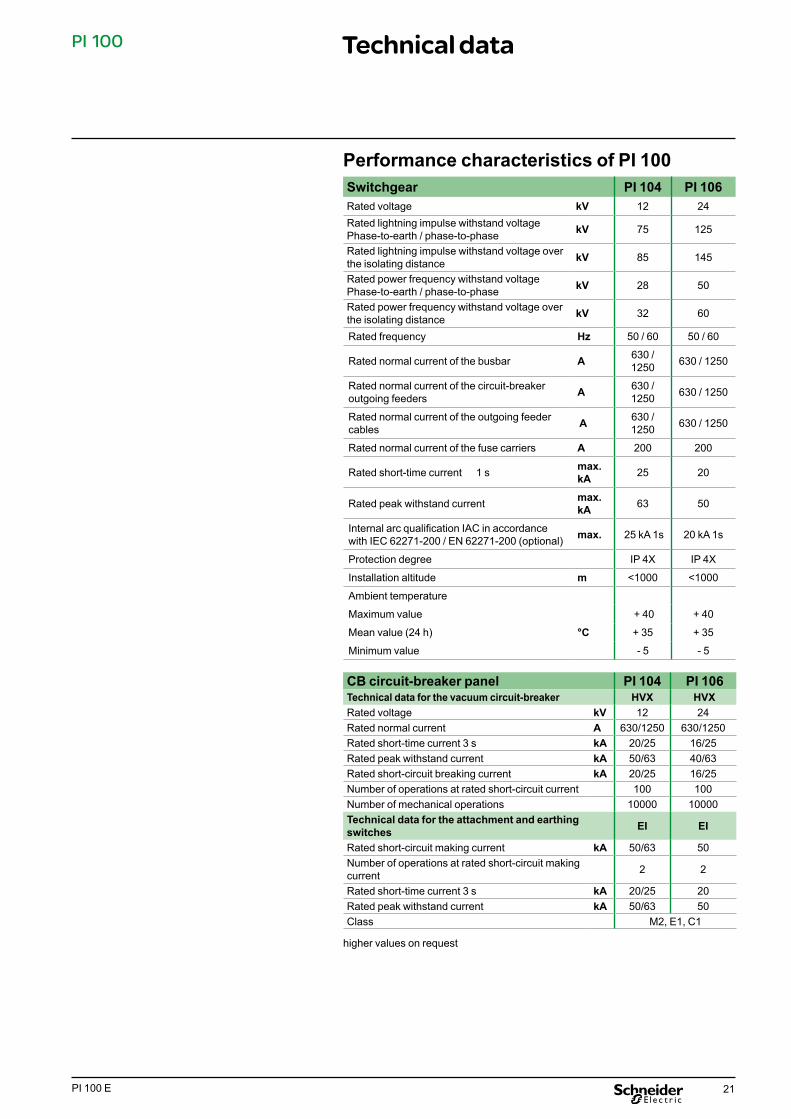
Performance characteristics of PI 100Switchgear PI 104 PI 106Rated voltage kV 12 24 Rated lightning impulse withstand voltage Phase-to-earth / phase-to-phase kV 75 125
Rated lightning impulse withstand voltage over the isolating distance kV 85 145
Rated power frequency withstand voltage Phase-to-earth / phase-to-phase kV 28 50
Rated power frequency withstand voltage over the isolating distance kV 32 60
Rated frequency Hz 50 / 60 50 / 60
Rated normal current of the busbar A 630 / 1250 630 / 1250
Rated normal current of the circuit-breaker outgoing feeders A 630 /
1250 630 / 1250
Rated normal current of the outgoing feeder cables A 630 /
1250 630 / 1250
Rated normal current of the fuse carriers A 200 200
Rated short-time current 1 s max. kA 25 20
Rated peak withstand current max. kA 63 50
Internal arc qualification IAC in accordance with IEC 62271-200 / EN 62271-200 (optional) max. 25 kA 1s 20 kA 1s
Protection degree IP 4X IP 4X
Installation altitude m <1000 <1000
Ambient temperature
Maximum value + 40 + 40
Mean value (24 h) °C + 35 + 35
Minimum value - 5 - 5
CB circuit-breaker panel PI 104 PI 106Technical data for the vacuum circuit-breaker HVX HVXRated voltage kV 12 24 Rated normal current A 630/1250 630/1250 Rated short-time current 3 s kA 20/25 16/25 Rated peak withstand current kA 50/63 40/63 Rated short-circuit breaking current kA 20/25 16/25 Number of operations at rated short-circuit current 100 100 Number of mechanical operations 10000 10000 Technical data for the attachment and earthing switches EI EI
Rated short-circuit making current kA 50/63 50 Number of operations at rated short-circuit making current 2 2
Rated short-time current 3 s kA 20/25 20 Rated peak withstand current kA 50/63 50 Class M2, E1, C1
higher values on request

22 PI 100 E
PI 100
Cable panel C and bus sectionalizer panel BS-SD PI 104 PI 106
Technical data for switch disconnector L-TRI 5/12...D
L-TRI 5/24...D
Rated voltage kV 12 24 Rated normal current A 630/1250 630/1250
Rated short-time current 1 s kA 25 25
3 s kA 18 18Rated peak withstand current kA 63 63 Rated short-circuit making current kA 63 63 Number of operations kA 2 2Rated closed-loop breaking current A 630/1250 630/1250 Rated mainly active load-breaking current A 630/1250 630/1250 Rated cable-charging breaking current A 50 50 Rated line-charging breaking current A 50 50 Rated earth fault breaking current A 150 285 Rated cable- and line-charging breaking current under earth fault conditions A 86 86
Number of mechanical operations 1500 1500 Technical data of attachment - earthing switches EA EA
Rated short-circuit making current kA 63 63 Number of operations 2 2Rated short-time current 1 s kA 25 25 3 s kA 14 14Rated peak withstand current kA 63 63 Class M1, E1
higher values on request
Transformer panel T1, T1M PI 104 PI 106Technical data for switch-fuse combination acc. to DIN VDE 0671-105, IEC 62271-105
L-TRI 5F/12... UH-KS-A
L-TRI 5F/24... UH-KS-A
Rated voltage kV 12 24 Rated normal current with fuse A 1) 1) Rated peak withstand current kA 63 63 Rated short-circuit making current kA 63 63 Number of operations 2 2Rated short-circuit breaking current kA 25 25 Rated mainly active load-breaking current A 400 400 Rated no-load transformer breaking current A 10 10 Rated cable-charging breaking current A 50 50 Rated line-charging breaking current A 50 50 Rated transfer current in case of striker operation A 1250 800
Fuse gauge mm 292 442 Type of admissible striker medium medium Number of mechanical operations 1500 1500 Technical data of attachment - earthing switches EU EU
Rated short-circuit making current kA 63 63 Number of operations 2 2Rated short-time current 1 s kA 25 25 3 s kA 14 14Rated peak withstand current kA 63 63 Class M1, E1
1) Limited by the rated current of the H.V.H.R.C. fuse links
Technical data (contd.)

23PI 100 E
PI 100 Electrical supplementary modules
Tripping range Power consumption
Release DesignationRated supply
voltageUa in [V]
Releasevoltageat DC
Releasevoltage at AC
50/60 Hz
at DCapprox.
[W]
at DC50/60 Hz
approx. [VA]
Closing coil F2
2448; 60
110; 120; 125220; 230
16 V to 40 V33 V to 66 V60 V to 140 V130 V to 260 V
250 250
Opening coilF11F12F13
2448; 60
110; 120; 125220; 230
16 V to 40 V33 V to 66 V60 V to 140 V130 V to 260 V
≤ 250 250
Undervoltagerelease F4
244860110125230
35 to 0 % Ua 10 10
Tripping range
Release DesignationRated current
Ia in [A]Release currentat AC 50/60 Hz
Transformeroperated release F30.515
-90to
100 % Ia
Power consumption and voltage ranges of the motor-operated drives
Power consumption and tripping ranges of the releases for LTS, E
Voltage range Power consumption of the motor
Rated currentFuse
Rated voltageof the drives max. min.
at DCat AC
50/60 Hz
Characteristics ofminiature circuit
breakersC [A]
Ua in [V] approx. [W] approx. [VA]
DC
244860110220
85 to 110 % Ua 200 -
4421
0.5
AC(110) 120(220) 230
132 V253 V
93 V187 V
- 200 0.5
Designation Number of switching elements
Rated (normal) current Breaking capacity
S11 8
15 A
at 48 V DC, L/R = 10 ms 10 A
S12 8at 125 V DC, L/R = 10 ms 3.8 Aat 220 V DC, L/R = 10 ms 2 Aat (110) (120(220) 230 V AC 10 A
Auxiliary switches and motor switches
One NC contact and one NO contact of the auxiliary switch respectively are required for each closing or opening coil respectively.

24 PI 100 E
PI 100 Electrical supplementary modules (contd.)
Motor driveAll the switch-disconnectors of the L-TRI 5 series and the earthing switches used in the PI switchgear can also be equipped with a motoroperated drive mechanism.The motor-operated drive mechanism is connected to the drive disc of the manual drive mechanism via a mechanical coupling. This coupling ensures that, in case of operating voltage loss, manual emergency operation of the switching device is possible with the door closed.
Shunt opening releaseA shunt opening release can be mounted to the L-TRI 5 switch disconnector equipped with an opening energy storage mechanism. The release is designed for pulse operation. After releasing the switchdisconnector, the circuit is opened by the corresponding auxiliary switch. Shunt opening releases are available for the following rated voltages.
Voltage limit ranges within which the releases work reliably
Type of release DC voltage AC voltage, 50/60 Hz
Shunt opening release (without/with auxiliary energy store) 0 up to 110 % Ua 85 up to 110 % Ua
Shunt closing release 85 up to 110 % Ua 85 up to 110 % UaUndervoltage release 35 up to 0 % Ua 35 up to 0 % Ua
Power consumptionDC
approx. [W]AC 50/60 Hzapprox. [VA]
Blocking coil 12
Motor-operated drive mechanism for switch disconnector and earthing switch
Shunt opening release mounted to a fuse-switch disconnector
Power consumption of the blocking coils

25PI 100 E
PI 100 Range of products
Un Ir Ik
(kV) (A) (kA)
12
24
Function code:
mm mm mm
C T1 T1M DI DIM
Un Ir Ik
(kV) (A) (kA)
12630
24
630
600800
800
900
Function code:
mm mm mm
BS-SD BS-SDF R RM M
WidthHeight Depth
Dimensions
Width Height Depth
Dimensiones
**
**
**) corresponds to internal arc classification IEC 62271-200***) 7,2 kV
Standard panels Options only ball pin
PI transformer panels
PI bus tie breaker panels
630 25 95022258001250
9008001250 20
63011502225
1250
630
630
600800
800
900
630 25 95022258001250
900800
20 1150222512506301250
Un Ir Ik
(kV) (A) (kA)
12
630
24
630
650
800
800
900
Function code:
mm mm mm
CB BC-CB MC***
Width Height **
Depth
Dimensions
650630 25 9502225
8001250
9008001250 20
63011502225
1250
1250
PI circuit-breaker and vacuum contactor panels
DIDT RDT
*) not possible in case of 24 kV
*
**
* *
*
**
Panel variants 12 kV / 24 kV

26 PI 100 E
PI 100 Range of products (contd.)
Type Function of feeder Function of panelCB Circuit Breaker feeder Circuit-breaker panel
T1 Transformer feeder Transformer panel
C Cable feeder Cable panel
R Riser feeder Bus riser panel (without switchgear)
DI Direct Iincomer Bus riser panel with cable connection
MC Motor control Center Motor Control Center
E Earthing switch Earthing switch
SD Switch Disconnector Switch disconnector
DT Disconnecting Truck Disconnecting truck
F Fuse Fuse
M Metering feeder or metering function
Metering panel or measuring function
BC-CB Bus Coupler with Circuit Breaker
Bus section coupler with circuit-breaker
BS-SD Bus Sectionalizer with Switch-Disconnector
Bus section coupler with switch disconnector
BB-VT Bus Bar - Voltage Transformer
Busbar voltage transformer
BB-ES Bus Bar - Earthing Switch Busbar earthing switch
.../... Combination of two feeders Combination of two panels
6 630 A 630 A
12 1250 A 1250 A
Function codes

27PI 100 E
PI 100 Design data
PI Leistungsschalter- und Vakuumschütz-Felder 12 kV
CBStandard panel Options
BC-CB
RDT
Optionen
Weight: 650 mm = approx. 360 kg
Weight:650 mm = approx. 380 kg
MC**
Branch circuit panel with- Circuit-breaker- Current transformer- Ball pin
Bus section coupler with- Circuit-breaker- Ball pin
DIDT
2225
650210 210185185
800 95019
00
730
235
with- Ball pin- Earthing switch- Surge arrester
Branch circuit panel with dis-connecting truck- Ball pin
with- Current transformer- Voltage transformer- Earthing switch
Weight:650 mm = approx. 330 kg800 mm = approx. 390 kg
Weight:650 mm = approx. 480 kg800 mm = approx. 520 kg
Weight:650 mm = approx. 340 kg800 mm = approx. 400 kg
Weight: 650 mm = approx. 475 kg800 mm = approx. 515 kg
Weight: 650 mm = approx. 550 kg800 mm = approx. 580 kg
Weight: 650 mm = approx. 480 kg800 mm = approx. 550 kg
Weight: 650 mm = approx. 385 kg800 mm = approx. 415 kg
Weight: 650 mm = approx. 475 kg800 mm = approx. 515 kg
Weight:650 mm = approx. 420 kg800 mm = approx. 480 kg
with- Current transformer- Voltage transformer- Earthing switch- Ball pin
Transmission with disconnecting truck- (Ball pin)
- Switch disconnector- Fuse attachment- Vacuum contactor- Current transformer- Ball pin
with- Earthing switch- Surge arrester
with- Current transformer- Ball pin
with- Current transformer
440
Standard panel
Standard panel Standard panel Standard panel
Options
Options Options
PI circuit-breaker and vacuum contactor panels 12 kV

28 PI 100 E
PI 100 Design data (contd.)
PI Abzweigfelder 12 kV
C T1
DI
853 11
3522
25
DIM
600210 210165165
800 950
1900
730
235
T1M
Busbar voltage transformer
300
320
BB-VT
BB-ES
Standard panel Options Standard panel Options
Cable panel with- Switch disconnector
- with ball pin or earthing switch
Transformer panel with- Switch disconnector- Fuse attachment
- with ball pin or earthing switch
Transformer panel with measurement- Switch disconnector- Fuse attachment- Current transformer- Voltage transformer
Weight:600 mm = approx. 200 kg800 mm = approx. 245 kg
Weight:600 mm = approx. 200 kg800 mm = approx. 245 kg
Weight:800 mm = approx. 300 kg
Weight:800 mm = approx. 390 kg
Bus riser panel - with ball pin Direct bus riser panel with measurement- Current transformers- Voltage transformers
- with ball pin
Standard panel Options
Standard panel Options Standard panel Options
Weight:600 mm = approx. 210 kg800 mm = approx. 250 kg
Weight:600 mm = approx. 225 kg800 mm = approx. 265 kg
Weight:600 mm = approx. 225 kg800 mm = approx. 265 kg
Weight:600 mm = approx. 240 kg800 mm = approx. 280 kg
Weight:800 mm = approx. 400 kg
Weight:800 mm = approx. 420 kg
- with ball pin or earthing switch
Busbar earthing
PI branch circuit panels 12 kV

29PI 100 E
PI 100
PI Übergabefelder 12 kV
BS-SD BS-SDF R
RM
853 11
3322
25
M
600210 210165165
800 950
1900
730
235
M
Standard panel Options Standard panel Options Standard panel Options
Standard panel Options Standard panel Options Standard panel Options
Weight:600 mm = approx. 230 kg800 mm = approx. 270 kg
Weight:600 mm = approx. 245 kg800 mm = approx. 285 kg
Weight:600 mm = approx. 245 kg800 mm = approx. 285 kg
Weight:600 mm = approx. 260 kg800 mm = approx. 300 kg
Weight:600 mm = approx. 200 kg800 mm = approx. 245 kg
Weight:600 mm = approx. 200 kg800 mm = approx. 245 kg
Weight:800 mm = approx. 390 kg
Weight:800 mm = approx. 390 kg
Weight:800 mm = approx. 490 kg
Weight:800 mm = approx. 490 kg
Weight:800 mm = approx. 340 kg
Weight:800 mm = approx. 340 kg
Cable panel with- Switch disconnector
- with ball pin or earthing switch
Transformer panel with- Switch disconnector- Fuse attachment
- with ball pin or earthing switch
Bus riser panel - with ball pin
Bus riser panel with measurement- Current transformers- Voltage transformers
- with ball pin Measurement in the busbar run with- Current transformer- Voltage transformer
- with ball pin Measurement in the busbar run with- Current transformer- Voltage transformer
- with ball pin
PI bus tie breaker panels 12 kV
Design data (contd.)
30 PI 100 E
PI 100
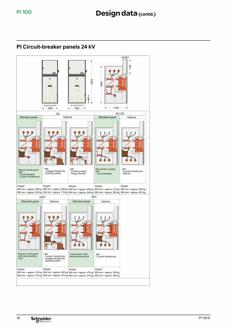
PI Leistungsschalter-Felder 24 kV
CB BC-CB
RDTDIDT
2225
210 210900 1150
1900
730
235
210 210800
440
Standard panel Options Standard panel Options
Weight:800 mm = approx. 470 kg900 mm = approx. 510 kg
Weight:800 mm = approx. 635 kg900 mm = approx. 675 kg
Weight:800 mm = approx. 470 kg900 mm = approx. 510 kg
Weight:800 mm = approx. 545 kg900 mm = approx. 585 kg
Weight:800 mm = approx. 585 kg900 mm = approx. 625 kg
Weight:800 mm = approx. 600 kg900 mm = approx. 715 kg
Weight:800 mm = approx. 600 kg900 mm = approx. 640 kg
Weight:800 mm = approx. 510 kg900 mm = approx. 550 kg
Weight:800 mm = approx. 585 kg900 mm = approx. 625 kg
Branch circuit panel with- Circuit-breaker- Current transformer
with- Voltage transformer- Earthing switch
with- Earthing switch- Surge arrester
Bus section coupler with- Circuit-breaker
with- Current transformer- Ball pin
Branch circuit panel with disconnecting truck
with- Current transformer- Voltage transformer- Earthing switch
Transmission with disconnecting truck
with- Current transformer
Standard panel OptionsStandard panel Options
PI Circuit-breaker panels 24 kV
Design data (contd.)
31PI 100 E
PI 100
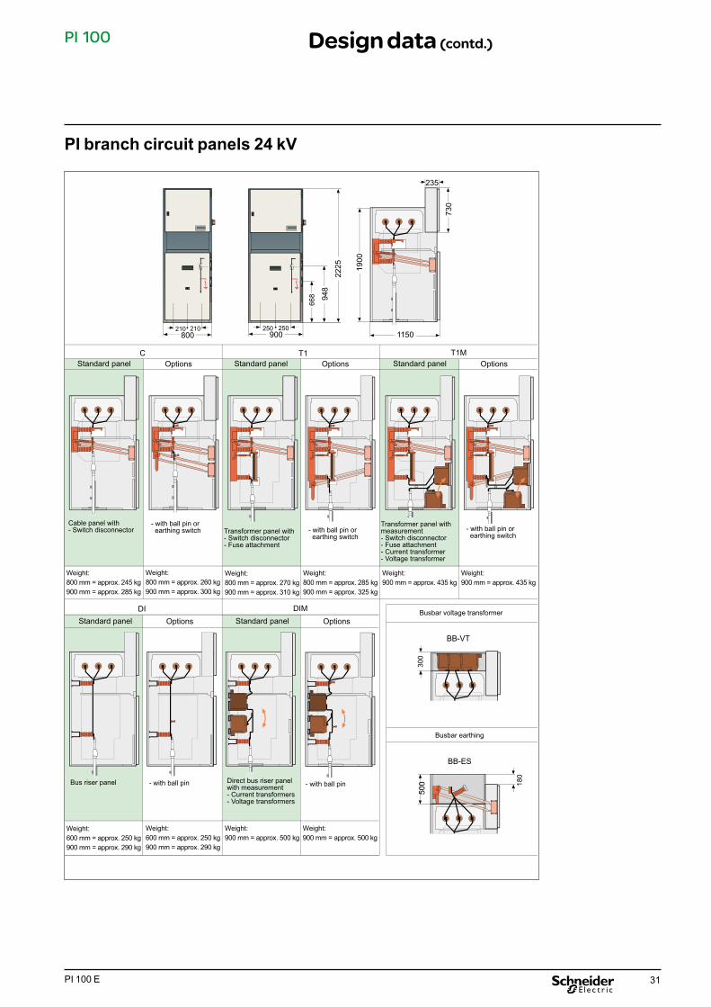
PI Abzweigfelder 24 kV
DI DIM
C T1 T1M
90094
8
668
800210 210 250 250
1150
1900
730
235
300
500
2225
180
Standard panel OptionsStandard panel Options
Standard panel OptionsStandard panel Options Standard panel Options
Cable panel with- Switch disconnector
- with ball pin or earthing switch Transformer panel with
- Switch disconnector- Fuse attachment
- with ball pin or earthing switch
Transformer panel with measurement- Switch disconnector- Fuse attachment- Current transformer- Voltage transformer
Bus riser panel - with ball pin Direct bus riser panel with measurement- Current transformers- Voltage transformers
- with ball pin
- with ball pin or earthing switch
Busbar voltage transformer
Busbar earthing
Weight:800 mm = approx. 245 kg900 mm = approx. 285 kg
Weight:800 mm = approx. 260 kg900 mm = approx. 300 kg
Weight:800 mm = approx. 270 kg900 mm = approx. 310 kg
Weight:800 mm = approx. 285 kg900 mm = approx. 325 kg
Weight:900 mm = approx. 435 kg
Weight:900 mm = approx. 435 kg
Weight:600 mm = approx. 250 kg900 mm = approx. 290 kg
Weight:600 mm = approx. 250 kg900 mm = approx. 290 kg
Weight:900 mm = approx. 500 kg
Weight:900 mm = approx. 500 kg
BB-VT
BB-ES
PI branch circuit panels 24 kV
Design data (contd.)

32 PI 100 E
PI 100
PI Übergabefelder 24 kV
BS-SD BS-SDF R
RM MM
900
1133
853
800210 210 250 250
115019
00
730
235
Standard panel OptionsStandard panel Options Standard panel Options
Standard panel OptionsStandard panel Options Standard panel Options
Weight:800 mm = approx. 275 kg900 mm = approx. 315 kg
Weight:800 mm = approx. 290 kg900 mm = approx. 330 kg
Weight:900 mm = approx. 350 kg
Weight:900 mm = approx. 350 kg
Weight:800 mm = approx. 250 kg900 mm = approx. 290 kg
Weight:800 mm = approx. 250 kg900 mm = approx. 290 kg
Weight:900 mm = approx. 500 kg
Weight:900 mm = approx. 500 kg
Weight:900 mm = approx. 715 kg
Weight:900 mm = approx. 715 kg
Weight:900 mm = approx. 565 kg
Weight:900 mm = approx. 565 kg
Cable panel with- Switch disconnector
- with ball pin or earthing switch
Transformer panel with- Switch disconnector- Fuse attachment
- with ball pin Bus riser panel - with ball pin
Bus riser panel with measurement- Current transformers- Voltage transformers
- with ball pin Measurement in the busbar run with- Current transformer- Voltage transformer
- with ball pin Measurement in the busbar run with- Current transformers- Voltage transformers
- with ball pin
PI bus tie breaker panels 24 kV
Design data (contd.)

33PI 100 E
PI 100
min.1500min.100
2225
950 (12kV)1150 (24 kV)
min
.240
0
Installation of the switchgear panelsThe switchgear compartment must comply with the requirements acc. to DIN VDE 0101 and HD 637 S1 and with the floor evenness / tolerance data acc. to DIN 43661. During the overall planning, the operating company must check whether the requirements on site relating to the switchgear (cable ducts, bushings, floor quality etc.) are met. Should it not be possible to fulfil the requirements regarding floor quality, we recommend installation of a base frame.
To fasten the panel to the floor or to the base frame, at least 2 diagonal screw fastenings are required.
The panels are designed for wall mounting. For a different mounting arrangement, please contact the manufacturer.
End plateThe switchgear units are provided with an end plate each for both ends.
Space requirements
Design data (contd.)

34 PI 100 E
PI 100 Design data (contd.)
Floor openings
Switchgear PI 104, 12 kV Fastening on double base1 Double base / concrete2 Compartment (cut-out) for HV and LV cable3 Steel base frame 40x40x24 Fastening bore-holes in the panel bottom5 Possible cross-bracings (not in case of metering panels M)6 Building wall7 Side plate of swichgear
Dimensional accuracy requirements regarding base frame:
Planeness / straightness / parallelism < 2 mm per meter
Upper edge of spacer bar or upper edge of finished floor = lower edge of panel.
Metering or bus tie breaker panels M, R, BS do not require cut-outs for high-voltage cables.
Switchgear PI 104, 12 kV Fastening on concrete
120
650600
7070
30
100±30
460 510
400
1 2 3 5
67
150150
60
950
100±
30
800
660 507070
160
830
790
80
4
20
800 (600)Panel width
Bus tie breaker or metering panels
80
180
6506007070
100±30
460 510
400
1 2 150150
950
100±
30
800
6607070
160
790
4
600(800)
Panel width
35PI 100 E
PI 100 Design data (contd.)
165
100±30
400
160
80070
66070
900
760
1000
86070 70
60
1150
100±
3010
3099
0
50 50
30
150150
1 2 4 53
67
20
165
100±30
400
160
80070
66070
900
760
1000
86070 70
1150
100±
3099
0
50 50
1501501 4
80
2
20
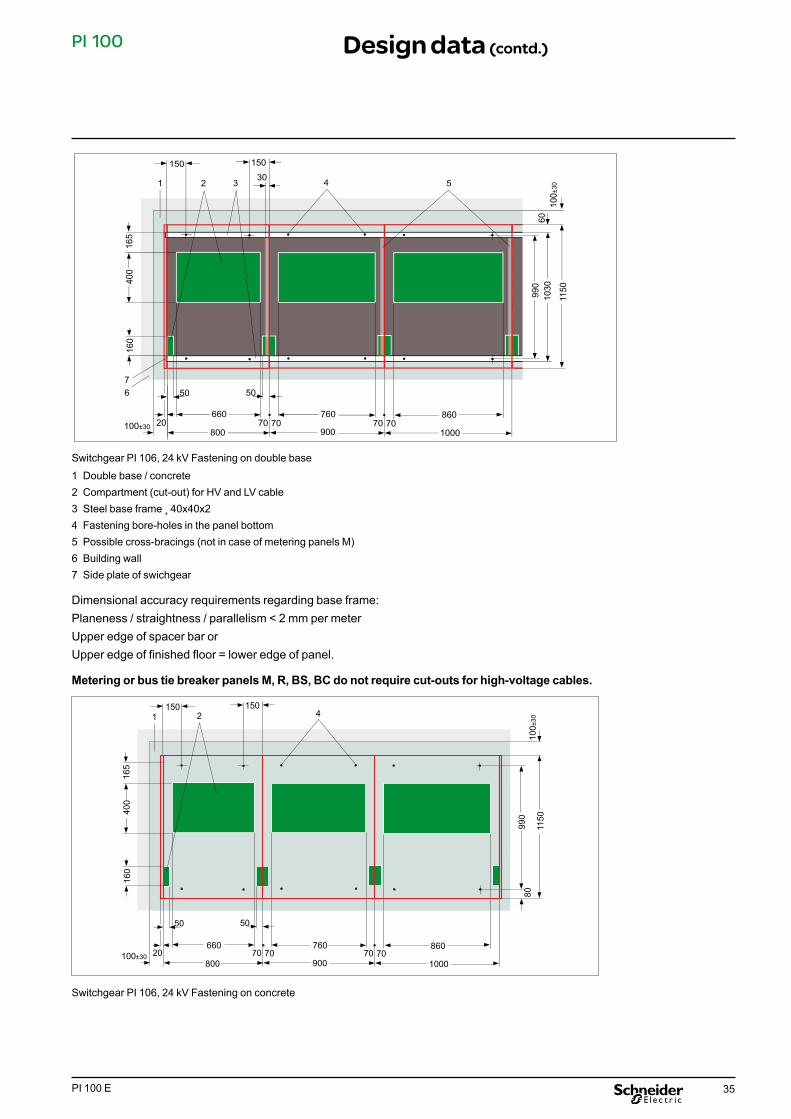
Switchgear PI 106, 24 kV Fastening on double base
Switchgear PI 106, 24 kV Fastening on concrete
1 Double base / concrete2 Compartment (cut-out) for HV and LV cable3 Steel base frame 40x40x24 Fastening bore-holes in the panel bottom5 Possible cross-bracings (not in case of metering panels M)6 Building wall7 Side plate of swichgear
Dimensional accuracy requirements regarding base frame:Planeness / straightness / parallelism < 2 mm per meterUpper edge of spacer bar orUpper edge of finished floor = lower edge of panel.
Metering or bus tie breaker panels M, R, BS, BC do not require cut-outs for high-voltage cables.

36 PI 100 E
PI 100 Design data (contd.)
60
100±
30
600 60050 50
130800 800
130600
630
750
950830
PN PI
1
Panel width
Switchgear combination PN / PI, 12 kV Fastening on double base
100±
30
600 60050 50
150
800 800
150
600
590
750
950790
PN PI
150 150
80
80
Panel width
Switchgear combination PN / PI, 12 kV Fastening on concrete
Dimensional accuracy requirements regarding base frame:Planeness / straightness / parallelism < 2 mm per meterUpper edge of spacer bar orupper edge of finished floor = lower edge of panel.
Metering or bus tie breaker panels M, R, BS, BC do not require cut-outs for high-voltage cables.
1 Possible cross-bracing
For detailed dimensions, refer to design data of PN and PI

37PI 100 E
PI 100 Shipping instructions
Transporting the panelsMake sure that the transported units do not slip or tilt during transport of the switchgear. When storing switchgear, observe the admissible conditions for operation. Condensation is not admissible.
The individual panels are delivered on pallets. Taking all the safety measures which have to be taken to protect persons and the transported equipment into consideration, transport can be performed by crane, forklift truck or elevating truck.
In connection with transport via crane, the crane mounting harness must be hooked into the jack rings of the individual panels or of the switchgear. The angle (upper edge of the panel - transport rope) must be > 60°.
Should there be no other possibility, transportation on a level surface can also be performed on transport rollers. However, all necessary safety measures must be taken into account. For further information, please refer to the applicable operating and assembly instructions.
Transport of single panels PI 104 or PI 106

38 PI 100 E
NotesAppendices

39PI 100 E
NotesAppendices
40 PI 100 E
PI 100
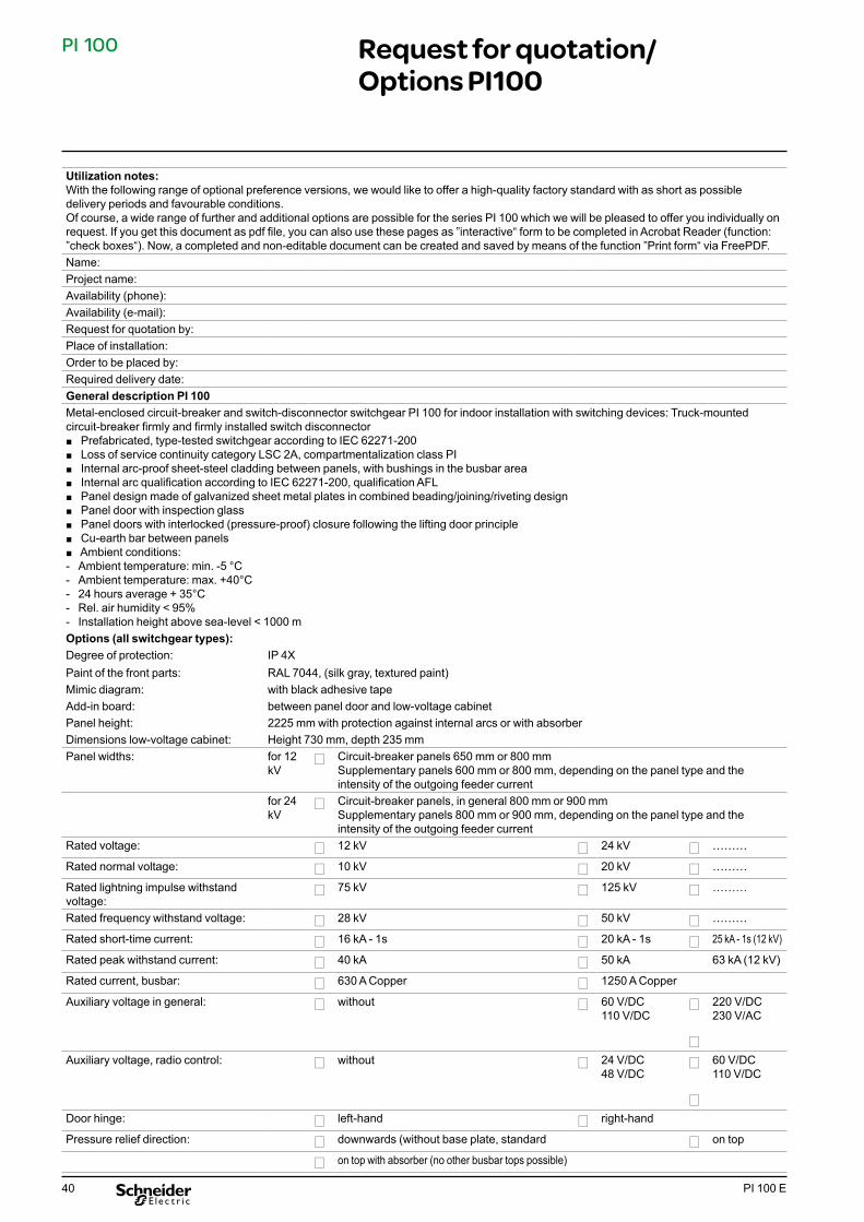
Utilization notes:With the following range of optional preference versions, we would like to offer a high-quality factory standard with as short as possible delivery periods and favourable conditions.Of course, a wide range of further and additional options are possible for the series PI 100 which we will be pleased to offer you individually on request. If you get this document as pdf file, you can also use these pages as ”interactive“ form to be completed in Acrobat Reader (function: ”check boxes“). Now, a completed and non-editable document can be created and saved by means of the function ”Print form“ via FreePDF. Name:Project name:Availability (phone):Availability (e-mail):Request for quotation by:Place of installation:Order to be placed by:Required delivery date:General description PI 100Metal-enclosed circuit-breaker and switch-disconnector switchgear PI 100 for indoor installation with switching devices: Truck-mounted circuit-breaker firmly and firmly installed switch disconnector
■ Prefabricated, type-tested switchgear according to IEC 62271-200 ■ Loss of service continuity category LSC 2A, compartmentalization class PI ■ Internal arc-proof sheet-steel cladding between panels, with bushings in the busbar area ■ Internal arc qualification according to IEC 62271-200, qualification AFL ■ Panel design made of galvanized sheet metal plates in combined beading/joining/riveting design ■ Panel door with inspection glass ■ Panel doors with interlocked (pressure-proof) closure following the lifting door principle ■ Cu-earth bar between panels ■ Ambient conditions: - Ambient temperature: min. -5 °C - Ambient temperature: max. +40°C - 24 hours average + 35°C - Rel. air humidity < 95% - Installation height above sea-level < 1000 m
Options (all switchgear types):Degree of protection: IP 4XPaint of the front parts: RAL 7044, (silk gray, textured paint)Mimic diagram: with black adhesive tapeAdd-in board: between panel door and low-voltage cabinetPanel height: 2225 mm with protection against internal arcs or with absorberDimensions low-voltage cabinet: Height 730 mm, depth 235 mmPanel widths: for 12
kV� Circuit-breaker panels 650 mm or 800 mm
Supplementary panels 600 mm or 800 mm, depending on the panel type and the intensity of the outgoing feeder current
for 24 kV
� Circuit-breaker panels, in general 800 mm or 900 mmSupplementary panels 800 mm or 900 mm, depending on the panel type and the intensity of the outgoing feeder current
Rated voltage: � 12 kV � 24 kV � ………
Rated normal voltage: � 10 kV � 20 kV � ………
Rated lightning impulse withstand voltage:
� 75 kV � 125 kV � ………
Rated frequency withstand voltage: � 28 kV � 50 kV � ………
Rated short-time current: � 16 kA - 1s � 20 kA - 1s � 25 kA - 1s (12 kV)
Rated peak withstand current: � 40 kA � 50 kA 63 kA (12 kV)
Rated current, busbar: � 630 A Copper � 1250 A Copper
Auxiliary voltage in general: � without � 60 V/DC110 V/DC
�
�
220 V/DC230 V/AC
Auxiliary voltage, radio control: � without � 24 V/DC48 V/DC
�
�
60 V/DC110 V/DC
Door hinge: � left-hand � right-hand
Pressure relief direction: � downwards (without base plate, standard � on top
� on top with absorber (no other busbar tops possible)
Request for quotation/ Options PI100

41PI 100 E
PI 100 Request for quotation/ Options PI100 (contd.)
CB Circuit-breaker panel (without outgoing voltage transformer)
Number of panel type: _______ Panel number(s) for installation order: _______________
Basic panel equipment: □ Vacuum circuit-breaker HVX with manual drive, auto-reclosing feature (AWE) and mechanical operations counter□ Mechanical operation of all switching devices with the front closed□ 1 cable connection with adjustable cable tether
Options: □ Rated current, HVX circuit breaker 630 A 1250 A
□ 1 set of ball pins in the outgoing feeder without D = 20 mm + earthing reference point M12 D = 25 mm + earthing reference point M16 □ without earthing switch□ Make-proof earthing switch with manual drive, earthing blade red, mechanical interlock circuit-breaker truck / earthing switch □ Additional cable connection with adjustable cable support without with 2nd cable connection and cable support with 3rd cable connection and cable support (only 12 kV) □ HVX without motor drive□ HVX with motor-operated drive wired up to the terminal strip□ HVX with motor drive with remote control package (2 ON+OFF coupling relays, ON/OFF release, ON/OFF pushbutton, change-over switch, ON/OFF remote control, miniature circuit-breaker - control, miniature circuit breaker - motor drive)□ Mimic diagram (sw) with position indicators without with mimic diagram without position indicator Indicator for circuit-breaker Indicator for earthing switch Indicator for truck/disconnecting position□ Undervoltage release on circuit-breaker without with □ Electric pulse stretcher (pulse contact) for breaker tripping signal without (pulse contact 10 ms) with (pulse contact stretched to 50 ms)□ Auxiliary switch at earthing switch without 4-pole (required for position indicator) 6-pole □ Locking facilities with lock cylinders (lock cylinders provided) without Panel door Actuation of earthing switch □ Current transformer, protection core (three-phase) (wired to terminals in LV cabinet)
75/1 A (5P10, 5VA) 100/1 A (5P10, 5VA) 200/1 A (5P10, 5VA) 300/1 A (5P10, 5VA) 400/1 A (5P10, 5VA) 600/1 A (5P10, 5VA) _____/__A (________, ______VA)

42 PI 100 E
PI 100 Request for quotation/ Options PI100 (contd.)
44
CB Circuit-breaker panel (without outgoing voltage transformer)
□ Current transformer, measuring core (1FS10, 5VA) (wired to terminals in LV cabinet) without 1-phase in L2 3-phase in L1-L3 (________, ______VA) □ Voltage detection system VDS in acc. with IEC 61243-5 without Pluggable HO system Integrated system IVIS (Schneider) Integrated system CAPDIS (Kries) □ Schneider protection relay (installation in door of low-voltage cabinet) in basic design P122C, UMZ, non-directed PS421, UMZ with transformer current release WA250 P130C, UMZ directed or motor protection P430C, distance protection P530C, cable differential protection □ Cable-type current transformer for recording current summation of low earth fault currents
without with, inside diameter 110 mm, one piece
with, inside diameter 115 mm, divisible
□ Test equipment (installation in rear plate) without Test socket Secu-Control (C14/2, B14/2 or B14/3)□ Moving-iron ammeter 72x72mm (installation in door of low-voltage cabinet) without, as displayed via Schneider protection relay 1-phase in L2 3-phase in L1-L3 □ Instrument transformer, current in phase L2 without Output 0-20mA (without auxiliary voltage) Output 4-20mA (only with auxiliary voltage) □ Signalling relay (electronic multiple drop indicator relay)
□ without □ Transformer temperature (release) [open-circuit current] □ Transformer temperature (warning) [open-circuit current] □ Buchholz (release) [open-circuit current] □ Buchholz (warning) [open-circuit current] □ Transformer, release (summation) [open-circuit current] □ Transformer, warning (summation) [open-circuit current] □ Protection OFF [open-circuit current] □ Collective fault (miniature circuit-breaker tripping, protection faulty and transformer signals, unless individual signals are required [closed-circuit current]□ Signalling relays (max. 4 signalling relays) □ without □ Transformer temperature (release) [open-circuit current] □ Transformer temperature (warning) [open-circuit current] □ Buchholz (release) [open-circuit current] □ Buchholz (warning) [open-circuit current] □ Transformer, release (summation) [open-circuit current] □ Transformer, warning (summation) [open-circuit current] □ Protection OFF [open-circuit current] □ Collective fault (miniature circuit-breaker tripping, protection faulty and transformer signals, unless individual signals are required [closed-circuit current]
Always 6 signalling relaysInstallation housing 96x96 Local and remote signalling Acknowledgement on site6 relay outputs (change-over contact) Closed-circuit and open-circuit current adjustable without batterywith EEPROM
Local and remote signallingAcknowledgement on site2 change-over contacts
Data: 60/1A Phase displacement 120¡ Power 1.2 VA Attachment in basement

43PI 100 E
PI 100
CB Circuit-breaker panel (without outgoing voltage transformer)
CB with VT Circuit-breaker panel with outgoing voltage transformer
Number of panel type: _______ Panel number(s) for installation order: _______________
Basic panel equipment: □ Vacuum circuit-breaker HVX with manual drive, auto-reclosing feature (AWE) and mechani -
cal operations counter□ Mechanical operation of all switching devices with the front closed□ 1 cable connection with adjustable cable tether
Options: □ Rated current, HVX circuit breaker 630 A 1250 A
□ 1 set of ball pins in the outgoing feeder without D = 20 mm + earthing reference point M12 D = 25 mm + earthing reference point M16 □ without earthing switch □ Make-proof earthing switch with manual drive, earthing blade in red, mechanical interlock circuit-breaker truck / earthing switch □ Additional cable connection with adjustable cable support without with 2nd cable connection and cable support □ HVX without motor drive □ HVX with motor-operated drive wired up to the terminal strip □ HVX with motor drive with remote control package (2 ON+OFF coupling relays, ON/OFF release, ON/OFF pushbutton, change-over switch, ON/OFF remote control, miniature circuit-breaker - control, miniature circuit breaker - motor drive)□ Mimic diagram (sw) with position indicators without with mimic diagram without position indicator Indicator for circuit-breaker Indicator for earthing switch Indicator for truck/disconnecting position□ Undervoltage release on circuit-breaker without with □ Electric pulse stretcher (pulse contact) for breaker tripping signal without (pulse contact 10 ms) with (pulse contact stretched to 50 ms)□ Auxiliary switch at earthing switch without 4-pole (required for position indicator) 6-pole
□ Transformer trip device 2 thermistor circuits without 1 x warning with, device type without time relay 1 x release with, device type with time relay
□ Panel interior illumination without with lamp (230 V/AC)
Request for quotation/ Options PI100 (contd.)

44 PI 100 E
PI 100
CB with VT Circuit-breaker panel with outgoing voltage transformer
Always 6 signalling relays Installation housing 96x96 Local and remote signalling Acknowledgement on site6 relay outputs (change-over contact) Closed-circuit and open-circuit current adjustable without batterywith EEPROM
□ Locking facilities with lock cylinders (lock cylinders provided) without Panel door Actuation of earthing switch □ Current transformer, protection core (three-phase) (wired to terminals in LV cabinet)
75/1 A (5P10, 5VA) 100/1 A (5P10, 5VA) 200/1 A (5P10, 5VA) 300/1 A (5P10, 5VA) 400/1 A (5P10, 5VA) 600/1 A (5P10, 5VA) ______/_ _ A (________, ______VA) □ Current transformer, measuring core (1FS10, 5VA) (wired to terminals in LV cabinet) 1-phase in L2 3-phase in L1-L3 (________, ______VA) □ Voltage detection system VDS in acc. with IEC 61243-5 without Pluggable HO system Integrated system IVIS (Schneider Electric) Integrated system CAPDIS (Kries) □ Schneider Electric protection relay (installation in door of low-voltage cabinet) in basic design P122C, UMZ, non-directed PS421, UMZ with transformer current release WA250 P130C, UMZ directed or motor protection P430C, distance protection P530C, cable differential protection □ Cable-type current transformer for recording current summation of low earth fault currents Data: 60/1A without Phase displacement 120° with, inside diameter 110 mm, one piece Power 1.2 VA with, inside diameter 115 mm, divisible Attachment in basement□ Test equipment (installation in rear plate) without Test socket Secu-Control (C14/2, B14/2 or B14/3) □ Moving-iron ammeter 72x72mm (installation in door of low-voltage cabinet) without, as displayed via Schneider Electric protection relay 1-phase in L2 3-phase in L1-L3 □ Instrument transformer, current in phase L2 without Output 0-20mA (without auxiliary voltage) Output 4-20mA (only with auxiliary voltage) □ Signalling relay (electronic multiple drop indicator relay)
- without - Transformer temperature (release) [open-circuit current] - Transformer temperature (warning) [open-circuit current] - Buchholz (release) [open-circuit current] - Buchholz (warning) [open-circuit current] - Transformer, release (summation) [open-circuit current] - Transformer, warning (summation) [open-circuit current] - Protection OFF [open-circuit current] - Collective fault (miniature circuit-breaker tripping, protection faulty and transformer signals, unless individual signals are required [closed-circuit current]
Request for quotation/ Options PI100 (contd.)

45PI 100 E
PI 100
CB with VT Circuit-breaker panel with outgoing voltage transformer
□ Signalling relays (max. 4 signalling relays) Local and remote □ without signalling □ Transformer temperature (release) [open-circuit current] Acknowledgement on □ Transformer temperature (warning) [open-circuit current] site □ Buchholz (release) [open-circuit current] 2 change-over contacts □ Buchholz (warning) [open-circuit current] □ Transformer, release (summation) [open-circuit current] □ Transformer, warning (summation) [open-circuit current] □ Protection OFF [open-circuit current] □ Collective fault (miniature circuit-breaker tripping, protection faulty and transformer signals, unless individual signals are required [closed-circuit current □ Transformer trip device 2 thermistor circuits without 1 x warning with, device type without timing relay 1 x release with, device type with time relay □ Panel interior illumination without with lamp (230 V/AC) □ Voltage transformer package (in outgoing feeder) with □ 3 single-pole voltage transformers □ 1 mini. circuit-breaker, main winding, three poles Optionally available: □ 1 miniature circuit-breaker for en winding, 1 pole with, Class 1. 75 VA □ 1 damping resistor with, Class 0.5, 45 VA □ 1 voltmeter 72x72mm with change-over switch, 6-step □ Instrument transformer, voltage between phase L1 and L3 without Output 0-20mA (without auxiliary voltage) Output 4-20mA (only with auxiliary voltage)
Request for quotation/ Options PI100 (contd.)
46 PI 100 E
PI 100
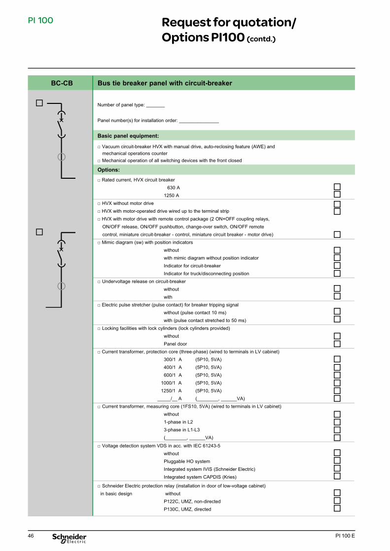
BC-CB Bus tie breaker panel with circuit-breaker
Number of panel type: _______ Panel number(s) for installation order: _______________
Basic panel equipment: □ Vacuum circuit-breaker HVX with manual drive, auto-reclosing feature (AWE) and mechanical operations counter□ Mechanical operation of all switching devices with the front closed
Options: □ Rated current, HVX circuit breaker 630 A 1250 A □ HVX without motor drive□ HVX with motor-operated drive wired up to the terminal strip□ HVX with motor drive with remote control package (2 ON+OFF coupling relays, ON/OFF release, ON/OFF pushbutton, change-over switch, ON/OFF remote control, miniature circuit-breaker - control, miniature circuit breaker - motor drive)□ Mimic diagram (sw) with position indicators without with mimic diagram without position indicator Indicator for circuit-breaker Indicator for truck/disconnecting position □ Undervoltage release on circuit-breaker without with □ Electric pulse stretcher (pulse contact) for breaker tripping signal without (pulse contact 10 ms) with (pulse contact stretched to 50 ms)□ Locking facilities with lock cylinders (lock cylinders provided) without Panel door □ Current transformer, protection core (three-phase) (wired to terminals in LV cabinet)
300/1 A (5P10, 5VA) 400/1 A (5P10, 5VA) 600/1 A (5P10, 5VA) 1000/1 A (5P10, 5VA) 1250/1 A (5P10, 5VA) _____/__ A (________, ______VA)□ Current transformer, measuring core (1FS10, 5VA) (wired to terminals in LV cabinet) without 1-phase in L2 3-phase in L1-L3 (________, ______VA)
□ Voltage detection system VDS in acc. with IEC 61243-5 without Pluggable HO system Integrated system IVIS (Schneider Electric) Integrated system CAPDIS (Kries)
□ Schneider Electric protection relay (installation in door of low-voltage cabinet) in basic design without P122C, UMZ, non-directed P130C, UMZ, directed
Request for quotation/ Options PI100 (contd.)

47PI 100 E
PI 100
BC-CB Bus tie breaker panel with circuit-breaker
□ Test equipment (installation in rear plate) without
Test socket Secu-Control (C14/2, B14/2) □ Moving-iron ammeter 72x72mm (installation in door of low-voltage cabinet) without, as displayed via Schneider Electric protection relay 1-phase in L2 3-phase in L1-L3 □ Instrument transformer, current in phase L2 without Output 0-20mA (without auxiliary voltage) Output 4-20mA (only with auxiliary voltage) □ Signalling relay Local and remote signalling without Acknowledgement on site Collective fault [Closed-circuit current] 2 change-over contacts
□ Panel interior illumination without with lamp (230 V/AC)
Request for quotation/ Options PI100 (contd.)

48 PI 100 E
PI 100
DIDT Direct bus riser with disconnecting truck
Number of panel type: _______ Panel number(s) for installation order: _______________
Basic panel equipment: □ Disconnecting truck□ Mechanical operation with the front panel closed
Options: □ Rated current, HVX circuit breaker 630 A 1250 A
□ 1 set of ball pins in the outgoing feeder without D = 20 mm + earthing reference point M12
D = 25 mm + earthing reference point M16□ without earthing switch□ Make-proof earthing switch with manual drive, earthing blade red, mechanical interlock truck / earthing switch
□ Additional cable connection with adjustable cable support without with 2nd cable connection and cable support □ Mimic diagram (sw) with position indicators without with mimic diagram without position indicator Indicator for earthing switch Indicator for truck/disconnecting position □ Auxiliary switch at earthing switch without 4-pole (required for position indicator) 6-pole □ Locking facilities with lock cylinders (lock cylinders provided) without Panel door Actuation of earthing switch □ Current transformer, protection core (three-phase) (wired to terminals in LV cabinet)
75/1 A (5P10, 5VA) 100/1 A (5P10, 5VA) 200/1 A (5P10, 5VA) 300/1 A (5P10, 5VA) 400/1 A (5P10, 5VA) 600/1 A (5P10, 5VA) _____/__ A (________, ______VA)□ Current transformer, measuring core (1FS10, 5VA) (wired to terminals in LV cabinet) 1-phase in L2 3-phase in L1-L3 (________, ______VA) □ Voltage detection system VDS in acc. with IEC 61243-5 without Pluggable HO system Integrated system IVIS (Schneider Electric) Integrated system CAPDIS (Kries)
Request for quotation/ Options PI100 (contd.)

49PI 100 E
PI 100
DIDT Direct bus riser with disconnecting truck
□ Moving-iron ammeter 72x72mm (installation in door of low-voltage cabinet) without, as displayed via Schneider Electric protection relay 1-phase in L2 3-phase in L1-L3 □ Instrument transformer, current in phase L2 without Output 0-20mA (without auxiliary voltage) Output 4-20mA (only with auxiliary voltage)□ Panel interior illumination without with lamp (230 V/AC) □ Voltage transformer package (in outgoing feeder) with: without □ 3 single-pole voltage transformers □ 1 circuit-breaker, main winding, three poles Optionally available: □ 1 automatic circuit-breaker for en winding, 1 pole - with, Class 1, 75 VA □ 1 damping resistor - with, Class 0.5, 45 VA □ 1 voltmeter 72x72mm with change-over switch, 6-step □ Instrument transformer, voltage between phase L1 and L3 without Output 0-20mA (without auxiliary voltage) Output 4-20mA (only with auxiliary voltage)
Request for quotation/ Options PI100 (contd.)

50 PI 100 E
PI 100
RDT Bus riser with disconnecting truck
Number of panel type: _______ Panel number(s) for installation order: _______________
Basic features of the panel:
□ Disconnecting truck□ Mechanical operation with the front panel closed Options: □ Rated current, HVX circuit breaker 630 A 1250 A
□ In case of max. 12 kV, 1 set of ball pins possible in the transfer area (bottom):
without
D = 20mm + earthing reference point M12
D = 25mm + earthing reference point M16 □ Mimic diagram (sw) with position indicators without with mimic diagram without position indicator Indicator for truck/disconnecting position □ Locking facilities with lock cylinders (lock cylinders provided) without Front door □ Current transformer, protection core (three-phase) (wired to terminals in LV cabinet) without 75/1 A (5P10, 5VA) 100/1 A (5P10, 5VA) 200/1 A (5P10, 5VA) 300/1 A (5P10, 5VA) 400/1 A (5P10, 5VA) 600/1 A (5P10, 5VA) _____/__ A (________, ______VA)□ Current transformer, measuring core (1FS10, 5VA) (wired to terminals in LV cabinet) without 1-phase in L2 3-phase in L1-L3 (________, ______VA) □ Moving-iron ammeter 72x72mm (installation in door of low-voltage cabinet) without, as displayed via Schneider Electric protection relay 1-phase in L2 3-phase in L1-L3 □ Instrument transformer, current in phase L2 without Output 0-20mA (without auxiliary voltage) Output 4-20mA (only with auxiliary voltage)
Request for quotation/ Options PI100 (contd.)

51PI 100 E
PI 100
MC7 Motor panel with vacuum contactor up to 7.2 kV
Number of panel type: _______ Panel number(s) for installation order: _______________
Basic panel equipment:
□ Fuse-switch disconnector combination L-TRI 5F with manual drive □ Mechanical operation of the switching devices with the front closed□ Schneider Electric vacuum contactor CBX3 exclusively with electrical actuation, test category AC4, rated current 400A, auxiliary switch attachment 6S/6Ö□ Fuse attachment with all-pole tripping, with tripping of contactor□ 1 cable connection with adjustable cable tether□ Contactor with remote control package (2 ON+OFF coupling relays, ON/OFF release, ON/OFF pushbutton, change-over switch, ON/OFF remote control, miniature circuit- breaker - control, miniature circuit breaker - motor drive)
Options:
□ 1 set of ball pins in the outgoing feeder without D = 20 mm + earthing reference point M12 D = 25 mm + earthing reference point M16 □ Make-proof earthing switch with manual drive, earthing blades in red, mechanical shaft interlocking to the switch disconnector □ Mimic diagram (sw) with position indicators without with mimic diagram without position indicator Indicator for switch disconnector Indicator for earthing switch Indicator for vacuum contactor □ Auxiliary switch on the fuse-switch disconnector without 4-pole 6-pole + Signalling switch, H.V.H.R.C. fuse tripped, 1NC/1NO contact □ Auxiliary switch at earthing switch without 4-pole 6-pole □ Locking facilities with lock cylinders (lock cylinders provided) without Panel door Actuation of switch disconnector Actuation of earthing switch □ Current transformer, protection core (three-phase) (wired to terminals in LV cabinet) 75/1 A (5P10, 5VA) 100/1 A (5P10, 5VA) 200/1 A (5P10, 5VA) 300/1 A (5P10, 5VA) 400/1 A (5P10, 5VA) _____/__ A (________, ______VA) □ Current transformer, measuring core (1FS10, 5VA) (wired to terminals in LV cabinet) without 1-phase in L2 3-phase in L1-L3 (________, ______VA)
S = NO contact; Ö = NC contact
Request for quotation/ Options PI100 (contd.)

52 PI 100 E
PI 100
MC7 Motor panel with vacuum contactor up to 7.2 kV
Data: 60/1A Phase displacement 120¡Power 1.2 VA Attachment in basement
□ Voltage detection system VDS in acc. with IEC 61243-5 without Pluggable HO system Integrated system IVIS (Schneider Electric) Integrated system CAPDIS (Kries) □ Schneider Electric Motor Control Center for medium-voltage motors in basic design without for door installation GEMSTART 5.4, Motor Control Center P122C, Motor and UMZ protection device P130C, UMZ directed with motor protection□ Cable-type current transformer for recording current summation of low earth fault currents without with, inside diameter 110 mm, one piece with, inside diameter 115 mm, divisible□ Instrument transformer, current in phase L2 without Output 0-20mA (without auxiliary voltage) Output 4-20mA (only with auxiliary voltage) □ Motor characteristics if H.V.H.R.C. fuses are included in enquiry: without Nominal power, motor _________ kW Nominal current, motor _________ A Maximum admissible start-up current _________ A Start-up time _________ s Number of starts per hour _________ □ 3 ZNO surge arresters without with □ Panel interior illumination without with lamp (230 V/AC)
Request for quotation/ Options PI100 (contd.)

53PI 100 E
PI 100
C Cable panel
Number of panel type: _______
Panel number(s) for installation order: _______________
Basic panel equipment:
□ Switch disconnector L-TRI 5 with manual drive□ Mechanical operation of all switching devices with the front closed□ 1 cable connection with adjustable cable tether
Options:
□ Rated current switch disconnector L-TRI 5
630 A
1250 A (12 kV)
□ 1 set of ball pins in the outgoing feeder
without
D = 20mm + earthing reference point M12
D = 25mm + earthing reference point M16 □ 1 set of ball pins towards the busbar side
without
D = 20mm + earthing reference point M12
D = 25mm + earthing reference point M16 □ without earthing switch □ Make-proof earthing switch with manual drive, earthing blade in red,
mechanical shaft interlocking to the switch disconnector
□ L-TRI without motor drive□ L-TRI with motor drive with remote control package (2 ON+OFF coupling relays,
ON/OFF release, ON/OFF pushbutton, change-over switch, ON/OFF remote
control, miniature circuit-breaker - control, miniature circuit breaker - motor drive)
□ Mimic diagram (sw) with position indicators
without
with mimic diagram without position indicator
Indicator for switch disconnector
Indicator for earthing switch □ Auxiliary switch at switch disconnector
without
4-pole
6-pole (required in case of motor-operated drive) □ Auxiliary switch at earthing switch
without
4-pole
6-pole (required in case of motor-operated drive on the LTRI) □ Locking facilities with lock cylinders (lock cylinders provided)
without
Panel door
Actuation of switch disconnector
Actuation of earthing switch □ Short-circuit indicator selection
without
Liquid indicator, bar attachment
ALPHA E
ALPHA M, resetting time: 2 h
ALPHA M, resetting time: 4 h
COMPACT, without pulse contact, D=30...42mm
OPTO F (3 LEDs); D=30…42 mm
OPTO F&E; D=30...42mm
Other type: ______________________ Indicate tripping
current setting: 400A 600A 1000A
Request for quotation/ Options PI100 (contd.)
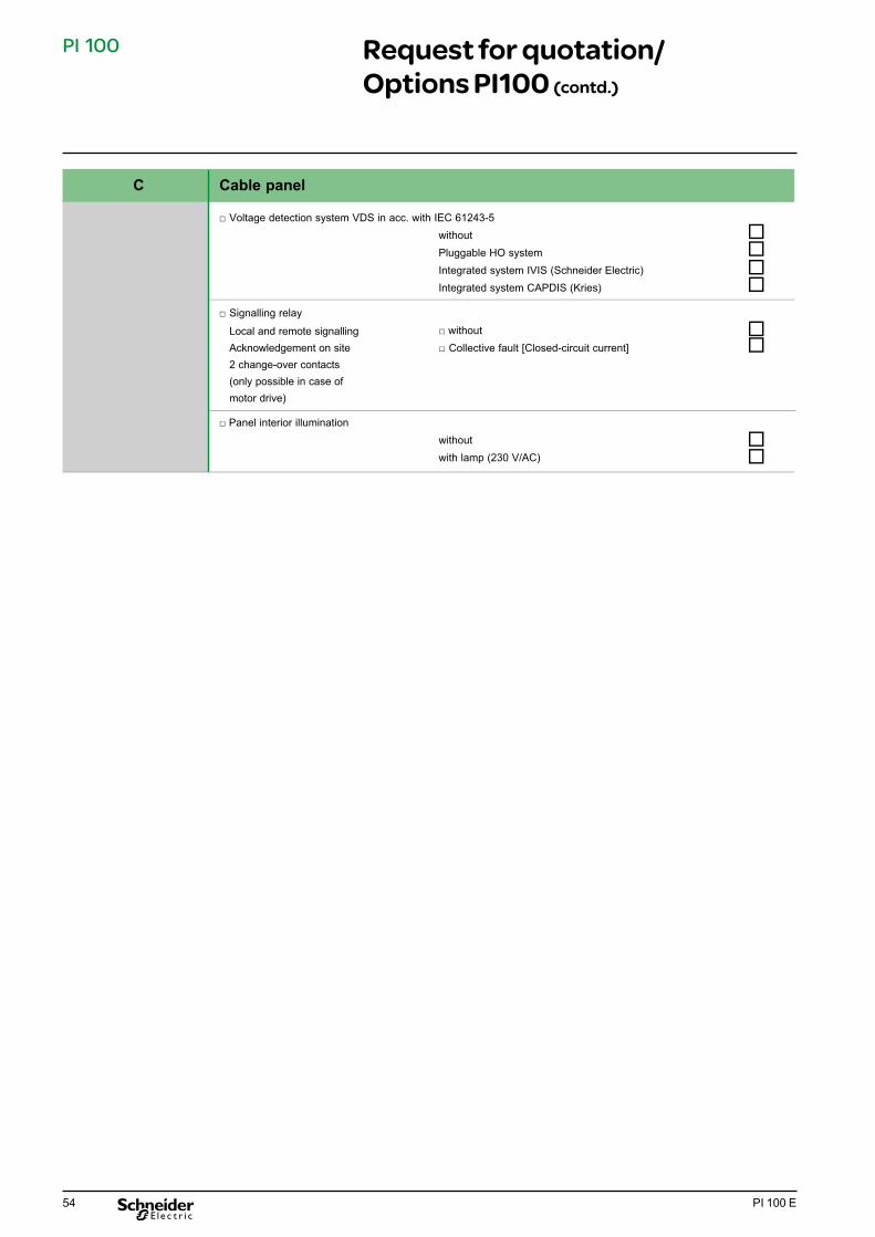
54 PI 100 E
PI 100
□ Voltage detection system VDS in acc. with IEC 61243-5 without Pluggable HO system Integrated system IVIS (Schneider Electric) Integrated system CAPDIS (Kries)
□ Signalling relay
□ without
□ Collective fault [Closed-circuit current]
□ Panel interior illumination without with lamp (230 V/AC)
C Cable panel
Local and remote signalling Acknowledgement on site2 change-over contacts(only possible in case of motor drive)
Request for quotation/ Options PI100 (contd.)

55PI 100 E
PI 100
T1 Transformer panel 630 A
Number of panel type: _______ Panel number(s) for installation order: _______________
Basic panel equipment:
□ Fuse-switch disconnector combination L-TRI 5F with manual drive □ Mechanical operation of all switching devices with the front closed□ 1 cable connection with adjustable cable tether
Options:
□ 1 set of ball pins in the outgoing feeder (for 12 kV) without D = 20mm + earthing reference point M12 D = 25mm + earthing reference point M16
□ 1 set of ball pins towards the busbar side without D = 20mm + earthing reference point M12 D = 25mm + earthing reference point M16
□ without earthing switch□ Make-proof earthing switch with manual drive, earthing blades in red, mechanical shaft interlocking to the switch disconnector
□ L-TRI without motor drive□ L-TRI with motor drive with remote control package (2 ON+OFF coupling relays, ON/OFF release, ON/OFF pushbutton, change-over switch, ON/OFF remote control, miniature circuit-breaker - control, miniature circuit breaker - motor drive) □ Mimic diagram (sw) with position indicators without with mimic diagram without position indicator Indicator for switch disconnector Indicator for earthing switch □ Auxiliary switch on the fuse-switch disconnector without 4-pole 10-pole (required in case of motor-operated drive) + Shunt opening release Specify tripping voltage: ___________ + Signalling switch, H.V.H.R.C. fuse tripped, 1NC/1NO contact □ Auxiliary switch at earthing switch without 4-pole 6-pole (required in case of motor-operated drive on the LTRI) □ Locking facilities with lock cylinders (lock cylinders provided) without Panel door Actuation of switch disconnector Actuation of earthing switch □ Voltage detection system VDS in acc. with IEC 61243-5 without Pluggable HO system Integrated system IVIS (Schneider Electric) Integrated system CAPDIS (Kries)
Request for quotation/ Options PI100 (contd.)

56 PI 100 E
PI 100
T1 Transformer panel 630 A
□ Signalling relay, max. 6 signalling relays (electronic drop indicator relay), only possible in case of motor drive □ without □ Transformer temperature (release) [open-circuit current] □ Transformer temperature (warning) [open-circuit current] □ Buchholz (release) [open-circuit current] □ Buchholz (warning) [open-circuit current] □ Transformer, release (summation) [open-circuit current] □ Transformer, warning (summation) [open-circuit current] □ Protection OFF [open-circuit current] □ Collective fault (circuit-breaker tripping, protection faulty and transformer signals, unless individual signals are required [closed-circuit current]
□ Signalling relay (max. 4 signalling relays, only possible in case of motor drive) □ without □ Transformer temperature (release) [open-circuit current]
□ Transformer temperature (warning) [open-circuit current] □ Buchholz (release) [open-circuit current] □ Buchholz (warning) [open-circuit current] □ Transformer, release (summation) [open-circuit current] □ Transformer, warning (summation) [open-circuit current] □ Protection OFF [open-circuit current] □ Collective fault (circuit-breaker tripping, protection faulty and transformer signals, unless individual signals are required [closed-circuit current]
□ Panel interior illumination without with lamp (230 V/AC)
Always 6 signalling relaysInstallation housing 96x96Acknowledgement on site6 relay outputs (change-over contact)Closed-circuit and open-circuit current separately adjustablewithout batterywith EEPROM
Only possible in case of motor drive!Local and remote signallingAcknowledgement on site2 change-over contacts
Request for quotation/ Options PI100 (contd.)
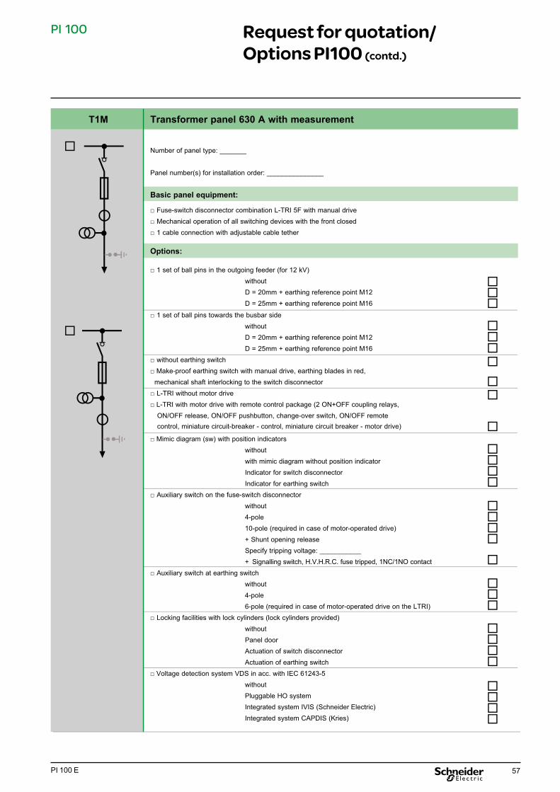
57PI 100 E
PI 100
Number of panel type: _______ Panel number(s) for installation order: _______________
Basic panel equipment: □ Fuse-switch disconnector combination L-TRI 5F with manual drive□ Mechanical operation of all switching devices with the front closed□ 1 cable connection with adjustable cable tether
Options:
□ 1 set of ball pins in the outgoing feeder (for 12 kV) without D = 20mm + earthing reference point M12 D = 25mm + earthing reference point M16
□ 1 set of ball pins towards the busbar side without D = 20mm + earthing reference point M12 D = 25mm + earthing reference point M16 □ without earthing switch□ Make-proof earthing switch with manual drive, earthing blades in red, mechanical shaft interlocking to the switch disconnector □ L-TRI without motor drive□ L-TRI with motor drive with remote control package (2 ON+OFF coupling relays, ON/OFF release, ON/OFF pushbutton, change-over switch, ON/OFF remote control, miniature circuit-breaker - control, miniature circuit breaker - motor drive)
□ Mimic diagram (sw) with position indicators without with mimic diagram without position indicator Indicator for switch disconnector Indicator for earthing switch □ Auxiliary switch on the fuse-switch disconnector without 4-pole 10-pole (required in case of motor-operated drive) + Shunt opening release Specify tripping voltage: ___________ + Signalling switch, H.V.H.R.C. fuse tripped, 1NC/1NO contact □ Auxiliary switch at earthing switch without 4-pole 6-pole (required in case of motor-operated drive on the LTRI) □ Locking facilities with lock cylinders (lock cylinders provided) without Panel door Actuation of switch disconnector Actuation of earthing switch □ Voltage detection system VDS in acc. with IEC 61243-5 without Pluggable HO system Integrated system IVIS (Schneider Electric) Integrated system CAPDIS (Kries)
T1M Transformer panel 630 A with measurement
Request for quotation/ Options PI100 (contd.)

58 PI 100 E
PI 100
T1M Transformer panel 630 A with measurement
□ Signalling relay (max. 6 signalling relays) (electronic drop indicator relay), only possible in case of motor drive) □ without □ Transformer temperature (release) [open-circuit current] □ Transformer temperature (warning) [open-circuit current] □ Buchholz (release) [open-circuit current] □ Buchholz (warning) [open-circuit current] □ Transformer, release (summation) [open-circuit current] □ Transformer, warning (summation) [open-circuit current] □ Protection OFF [open-circuit current] □ Collective fault (circuit-breaker tripping, protection faulty and transformer signals, unless individual signals are required [closed-circuit current]
□ Signalling relay (max. 4 signalling relays, only possible in case of motor drive) □ without □ Transformer temperature (release) [open-circuit current] □ Transformer temperature (warning) [open-circuit current] □ Buchholz (release) [open-circuit current] □ Buchholz (warning) [open-circuit current] □ Transformer, release (summation) [open-circuit current] □ Transformer, warning (summation) [open-circuit current] □ Protection OFF [open-circuit current] □ Collective fault (circuit-breaker tripping, protection faulty and transformer signals, unless individual signals are required [closed-circuit current]
□ Panel interior illumination without with lamp (230 V/AC)
□ 3 current transformers for billing metering Primary current: ______A Core 1: ___ A Class: ________ Power: _____ VA Core 2: ___ A Class: ________ Power: _____ VA without To be supplied by Schneider Electric Provision acc. to DIN 42600 part 8 (slim design) Provision not acc. to DIN 42600 part 8 (slim design)
□ 3 voltage transformers for billing metering (single-pole) Primary voltage: ______kV Measuring winding 1: ______ V Class: ________ Power: ____ VA Measuring winding 2: ______ V Class: ________ Power: ____ VA without To be supplied by Schneider Electric Provision acc. to DIN 42600 part 9 (slim design) Provision not acc. to DIN 42600 part 9 (slim design) Provision of 2 double-pole transformers □ Damping resistor without with and protection via miniature circuit-breaker
Always 6 signalling relays Installation housing 96x96 Local and remote signalling Acknowledgement on site 6 relay outputs (change-over contact)Closed-circuit and open-circuit current adjustable without battery with EEPROM
Only possible in case of motor drive!
Local and remote signalling Acknowledgement on site 2 change-over contacts
Request for quotation/ Options PI100 (contd.)

59PI 100 E
PI 100
DI Direct bus riser
Number of panel type: _______ Panel number(s) for installation order: _______________
Basic panel equipment:
□ 1 cable connection with adjustable cable tether
Options: □ Rated current 630 A 1250 A
□ Additional cable connection with adjustable cable support without with 2nd cable connection and cable support
□ 1 set of ball pins in the outgoing feeder without D = 20 mm + earthing reference point M12 D = 25 mm + earthing reference point M16
□ Locking facilities with lock cylinders (lock cylinders provided) without Front door
□ Voltage detection system VDS in acc. with IEC 61243-5 without Pluggable HO system Integrated system IVIS (Schneider Electric) Integrated system CAPDIS (Kries)
Request for quotation/ Options PI100 (contd.)

60 PI 100 E
PI 100
DIM Direct bus riser with measurement
Number of panel type: _______ Panel number(s) for installation order: _______________
Basic panel equipment:
□ 1 cable connection with adjustable cable tether
Options: □ Rated current, HVX circuit breaker 630 A 1250 A □ Additional cable connection with adjustable cable support without with 2nd cable connection and cable support
□ 1 set of ball pins in the outgoing feeder without D = 20 mm + earthing reference point M12 D = 25 mm + earthing reference point M16 □ 1 set of ball pins towards the busbar side without D = 20mm + earthing reference point M12 D = 25mm + earthing reference point M16 □ Locking facilities with lock cylinders (lock cylinders provided) without Panel door □ 3 current transformers for billing metering Primary current: ______A Core 1: ___ A Class: ________ Power: ____ VA Core 2: ___ A Class: ________ Power: ____ VA without To be supplied by Schneider Electric Provision acc. to DIN 42600 part 8 (slim design) Provision not acc. to DIN 42600 part 8 (slim design) □ 3 voltage transformers for billing metering (single-pole)
Primary voltage: ______kV Measuring winding 1: ______ V Class: ________ Power: ____ VA Measuring winding 2: ______ V Class: ________ Power: ____ VA without To be supplied by Schneider Electric Provision acc. to DIN 42600 part 9 (slim design) Provision not acc. to DIN 42600 part 9 (slim design) Provision of 2 double-pole transformers
□ Damping resistor without with and protection via miniature circuit-breaker
Request for quotation/ Options PI100 (contd.)
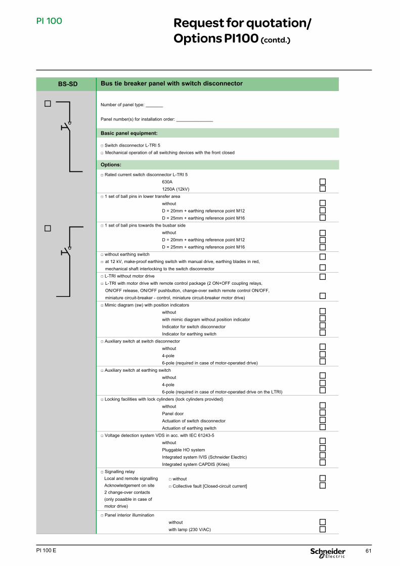
61PI 100 E
PI 100
BS-SD Bus tie breaker panel with switch disconnector
Local and remote signallingAcknowledgement on site2 change-over contacts(only poaaible in case of motor drive)
Number of panel type: _______ Panel number(s) for installation order: _______________
Basic panel equipment:
□ Switch disconnector L-TRI 5□ Mechanical operation of all switching devices with the front closed
Options: □ Rated current switch disconnector L-TRI 5
630A 1250A (12kV) □ 1 set of ball pins in lower transfer area without D = 20mm + earthing reference point M12 D = 25mm + earthing reference point M16 □ 1 set of ball pins towards the busbar side without D = 20mm + earthing reference point M12 D = 25mm + earthing reference point M16 □ without earthing switch□ at 12 kV, make-proof earthing switch with manual drive, earthing blades in red, mechanical shaft interlocking to the switch disconnector □ L-TRI without motor drive □ L-TRI with motor drive with remote control package (2 ON+OFF coupling relays, ON/OFF release, ON/OFF pushbutton, change-over switch remote control ON/OFF, miniature circuit-breaker - control, miniature circuit-breaker motor drive) □ Mimic diagram (sw) with position indicators without with mimic diagram without position indicator Indicator for switch disconnector Indicator for earthing switch □ Auxiliary switch at switch disconnector without 4-pole 6-pole (required in case of motor-operated drive) □ Auxiliary switch at earthing switch without 4-pole 6-pole (required in case of motor-operated drive on the LTRI) □ Locking facilities with lock cylinders (lock cylinders provided) without Panel door Actuation of switch disconnector Actuation of earthing switch □ Voltage detection system VDS in acc. with IEC 61243-5 without Pluggable HO system Integrated system IVIS (Schneider Electric) Integrated system CAPDIS (Kries) □ Signalling relay □ without □ Collective fault [Closed-circuit current]
□ Panel interior illumination without with lamp (230 V/AC)
Request for quotation/ Options PI100 (contd.)

62 PI 100 E
PI 100
BS-SDF Bus tie breaker panel with fuse switch disconnector 630 A
Local and remote signallingAcknowledgement on site2 change-over contacts(only possible in case of motor drive)
Number of panel type: _______
Panel number(s) for installation order: _______________
Basic panel equipment: □ Fuse-switch disconnector combination L-TRI 5F with manual drive
□ Mechanical operation of all switching devices with the front closed
Options: □ 1 set of ball pins in the outgoing feeder / transfer (for 12 V) without D = 20mm + earthing reference point M12 D = 25mm + earthing reference point M16
□ 1 set of ball pins towards the busbar side without
D = 20mm + earthing reference point M12 D = 25mm + earthing reference point M16
□ without earthing switch□ at 12 kV, make-proof earthing switch with manual drive, earthing blades in red, mechanical shaft interlocking to the switch disconnector
□ L-TRI without motor drive □ L-TRI with motor drive with remote control package (2 ON+OFF coupling relays, ON/OFF release, ON/OFF pushbutton, change-over switch remote control ON/OFF, miniature circuit-breaker - control, miniature circuit-breaker motor drive)
□ Mimic diagram (sw) with position indicators without
with mimic diagram without position indicator Indicator for switch disconnector Indicator for earthing switch
□ Auxiliary switch at switch disconnector without 4-pole 10-pole (required in case of motor-operated drive) + Shunt opening release Specify tripping voltage: ___________
+ Signalling switch, H.V.H.R.C. fuse tripped, 1NC/1NO contact
□ Auxiliary switch at earthing switch without 4-pole 6-pole (required in case of motor-operated drive on the LTRI)
□ Locking facilities with lock cylinders (lock cylinders provided) without Panel door Actuation of switch disconnector Actuation of earthing switch
□ Voltage detection system VDS in acc. with IEC 61243-5 without Pluggable HO system Integrated system IVIS (Schneider Electric) Integrated system CAPDIS (Kries)
□ Signalling relay - without - Collective fault [Closed-circuit current]
□ Panel interior illumination without
with lamp (230 V/AC)
Request for quotation/ Options PI100 (contd.)
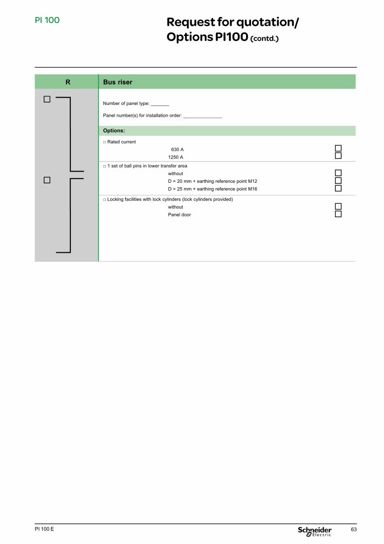
63PI 100 E
PI 100
R Bus riser
Number of panel type: _______ Panel number(s) for installation order: _______________
Options: □ Rated current
630 A
1250 A
□ 1 set of ball pins in lower transfer area without D = 20 mm + earthing reference point M12 D = 25 mm + earthing reference point M16
□ Locking facilities with lock cylinders (lock cylinders provided) without Panel door
Request for quotation/ Options PI100 (contd.)

64 PI 100 E
PI 100
RM Bus riser with measurement
Number of panel type: _______ Panel number(s) for installation order: _______________
Options: □ Rated current 630 A 1250 A
□ 1 set of ball pins, top, towards the busbar side (above the transformer) without D = 20 mm + earthing reference point M12 D = 25 mm + earthing reference point M16 □ 1 set of ball pins, bottom (below the transformer) without D = 20 mm + earthing reference point M12 D = 25 mm + earthing reference point M16 □ Locking facilities with lock cylinders (lock cylinders provided) without Panel door □ 3 current transformers for billing metering Primary current: ______A Core 1: ___ A Class: ________ Power: ____ VA Core 2: ___ A Class: ________ Power: ____ VA without To be supplied by Schneider Electric Provision acc. to DIN 42600 part 8 (slim design) Provision not acc. to DIN 42600 part 8 (slim design) □ 3 voltage transformers for billing metering (single-pole) Primary voltage: ______kV Measuring winding 1: ______ Class: ________ Power: ____ VA Measuring winding 2: ______ Class: ________ Power: ____ VA without To be supplied by AREVA Provision acc. to DIN 42600 part 9 (slim design) Provision not acc. to DIN 42600 part 9 (slim design) Provision of 2 double-pole transformers
□ Damping resistor without with and protection via miniature circuit-breaker
Request for quotation/ Options PI100 (contd.)

65PI 100 E
PI 100
M Transfer measurement
Number of panel type: _______ Panel number(s) for installation order: _______________
Options: □ Rated current 630 A 1250 A
□ 1 set of ball pins, top, towards the busbar side (above the transformer)
without
D = 20 mm + earthing reference point M12
D = 25 mm + earthing reference point M16
□ 1 set of ball pins, bottom (below the transformer)
without
D = 20 mm + earthing reference point M12
D = 25 mm + earthing reference point M16
□ Locking facilities with lock cylinders (lock cylinders provided) without
Panel door
□ 3 current transformers for billing metering
Primary current: ______A
Core 1: ___ A Class: ________ Power: ____ VA
Core 2: ___ A Class: ________ Power: ____ VA
without
To be supplied by Schneider Electric
Provision acc. to DIN 42600 part 8 (slim design)
Provision not acc. to DIN 42600 part 8 (slim design)
□ 3 voltage transformers for billing metering (single-pole)
Primary voltage: ______kV
Measuring winding 1: ______ Class: ________ Power: ____ VA
Measuring winding 2: ______ Class: ________ Power: ____ VA
without To be supplied by Schneider Electric Provision acc. to DIN 42600 part 9 (slim design) Provision not acc. to DIN 42600 part 9 (slim design)
Provision of 2 double-pole transformers
□ Damping resistor without
with and protection via miniature circuit-breaker
□ 3 current transformers for comparative
Primary current: ______A Core 1: ___ A Class: ________ Power: ____ VA
Core 2: ___ A Class: ________ Power: ____ VA
without
To be supplied by Schneider Electric
Provision acc. to DIN 42600 part 8 (slim design)
Provision not acc. to DIN 42600 part 8 (slim design)
Request for quotation/ Options PI100 (contd.)

66 PI 100 E
PI 100
M Transfer measurement
□ 3 voltage transformers for comparative measurement (single pole)
Primary voltage: ______ kV Measuring winding 1: ______ V Class: ________ Power: ____ VA
Measuring winding 2: ______ V Class: ________ Power: ____ VA
without
To be supplied by Schneider Electric
Provision acc. to DIN 42600 part 8 (slim design)
Provision not acc. to DIN 42600 part 8 (slim design)
Provision of 2 double-pole transformers
□ 2nd damping resistor without
with and protection via miniature circuit-breaker
BB-VT Busbar voltage transformer
Local and remote signallingAcknowledgement on site2 change-over contacts
Number of modules (top-mounted box): _______ Pertaining to panel number(s): _______________
Options: □ Voltage transformer package with: □ 3 single-pole voltage transformers □ 1 miniature circuit-breaker, main winding, three poles Optionally available: □ 1 min. circuit-breaker for en winding, 1 pole □ with category 1. 75 VA □ 1 damping resistor □ with category 0.5, 45 VA □ 1 voltmeter 72x72 mm
with change-over switch, 6-step
□ Instrument transformer, voltage between phase L1 and L3 without
Output 0-20mA (without auxiliary voltage) Output 4-20mA (only with auxiliary voltage)
□ Schneider Electric protection relay for earth fault detection, single-phase, type MU 633 1-phase in neutral without with □ Signalling relay □ without □ Earth fault [Open-circuit current] (MU 633 required)
Request for quotation/ Options PI100 (contd.)

67PI 100 E
PI 100
BB-ES Busbar earthing switch
Number of modules (top-mounted box): _______ Access to panel number(s): _______________
Basic panel equipment: □ Make-proof earthing switch with manual drive, earthing blade in red,□ Mechanical actuation of earthing switch on the front side□ Locking feature: device for padlock
Options: □ Auxiliary switch at busbar earthing switch without 4-pole 6-pole
Request for quotation/ Options PI100 (contd.)

PI 100 E 02-2011
© 2
011
Sch
neid
er E
lect
ric -
All
right
s re
serv
ed
As standards, specifications and designs change from time to time, please ask for confirmation of the information given in this publication.
Publishing: Schneider ElectricDesign: Schneider ElectricPrinting:
This document has been printed on ecological paper
Schneider Electric35, rue Joseph Monier CS 30323 92506 Rueil-Malmaison Cedex, France
RCS Nanterre 954 503 439 Capital social 896 313 776 €www.schneider-electric.com