Embed Size (px)
Citation preview

KEVA CIndoor voltage sensors
Medium Voltage Products

2 KEVA C | Indoor voltage sensor
Us =
R2
R1 + R2
Up
Parameters for Application Value
Rated primary voltage of application up to 24 kV
Sensor Parameters Value
Rated primary voltage, Upn 22/√3 kV
Highest voltage for equipment, Um 24 kV
Rated power frequency withstand voltage 50 kV
Rated lightning impulse withstand voltage 125 kV
Rated transformation ratio, Kn
for voltage measurement
10 000:1
Voltage accuracy class 0.5/3P
Length of cable 2.2; 5 m
Sensor principlesElectronic Instrument Transformers (Sensors) offer an alter-native way of making the voltage measurement needed for the protection and monitoring of medium voltage power sys-tems. Sensors based on alternative principles have been in-troduced as successors to conventional instrument transform-ers in order to significantly reduce size, increase safety, and to provide greater rating standardization and a wider functionality range. These well known principles can only be fully utilized in combination with versatile electronic relays.
Sensor characteristicsConstruction of ABB’s voltage sensors is done without the use of a ferromagnetic core. This fact results in several important benefits for the user and the application. The main benefit is that the behavior of the sensor is not in-fluenced by non-linearity and width of hysteresis curve, which results in a highly accurate and linear response over a wide dy-namic range of measured quantities. A linear and highly accurate sensor characteristic in the full operating range enables the com-bination of metering and protection classes in one device.
Voltage sensorVoltage measurement in KEVA C sensors is based on the re-sistive divider principle. The output voltage is directly propor-tional to the input voltage:
Fig. 1. Resistive divider principle
In all cases, the transmitted output signal reproduces the actual waveform of the primary voltage signal.
Protection and control IEDs (Intelligent Electronic Devices)Protection and control IEDs incorporate the functions of a traditional relay, as well as allow new additional functions. The information transmitted from the sensors to the IED is very accurate, providing the possibility of versatile relay functionality. However, the IED must be able to operate with sufficient ac-curacy at a sensor’s low input signal level. Modern IEDs (such as ABB’s 615 series relays) are designed for such sensor use. Modern digital apparatuses (microprocessor based relays) allow protection and measurement functions to be combined. They fully support voltage sensing realized by the single sen-sor with double the accuracy class designation (e.g.: voltage sensing with combined accuracy class 0.5/3P).
Fig. 2. IED and sensor
Sensor applicationsThe voltage sensors type KEVA C are intended for use in voltage measurement in gas insulated medium voltage switch-gear. The voltage sensors are designed as easy replacement of originally used insulating plugs in the cable connectors. Due to their compact size and optimized design sensors can be used for retrofit purposes as well as in new installations.
Fig. 3. KEVA C application

KEVA C | Indoor voltage sensor 3
Sensor variants
Sensor type designation Metal coated (conductive surface) Picture
KEVA 24 Cxy
KEVA 24 Cxyc
Note: Voltage sensor KEVA 24 C30 is available only in sensor design variant without conductive surface.
Tab. 1. Sensor design variants (with and without conductive surface)
Sensor type designation
Cable connectors
Manufacturer Type Connecting screw for sensor
KEVA 24 C10KEVA 24 C10c
Nexans-Euromold
400 TB/G
M16
440 TB/GK400 TB/GK440 TB/G400PB-xSA
Cellpack CTS-S 630A
Prysmian
FMCTs-400FMCTs-400/1250 (C/D)FMCTXs-630/CMSCT/EC-630-C
SüdkabelSEHDT 13, 23MUT 33
KEVA 24 C21KEVA 24 C21c NKT (ABB) Kabeldon
CSE-A 12630
M16CSEP-A 12630CSE-A 24630CSEP-A 24630SOC 630 (older)
KEVA 24 C22KEVA 24 C22c
NKT
CB 12-630
M12
CC 12-630CB 24-630CC 24-630
TE connectivity-RaychemRSTI L56xxRSTI-CC L56xx
KEVA 24 C23KEVA 24 C23c
TE connectivity-RaychemRSTI 58xx/39xx
M16(For use in NKT connectors with M16 screw shall be used the correct screw)
RSTI-CC 58xx/39xxRSTI LCxx/LAxx (older)
NKT
CB 12-630CC 12-630CB 24-630CC 24-630
KEVA 24 C24KEVA 24 C24c
Nexans-Euromold
430 TB - 630A
M16
K430 TB - 630A300 PB - 630AK300 PB - 630A
PrysmianFMCEAs 630/400MSCEA/EC-630-C
KEVA 24 C25KEVA 24 C25c Cellpack
CTS 630A 24kVM16
CTKS 630A 24 kV
KEVA 24 C26KEVA 24 C26c Südkabel
SET 12, 24
M16
SEHDK 13.1, 23.1SEHDT 13.1, 23.1MUT 23.1AD 23.1 SPSAT 12, 24SAK 12, 24
KEVA 24 C30 TE connectivity-Raychem RICS 51x3, 51x9, 51x7 M16
Note: For use in alternative cable connectors please contact ABB.
Tab. 2. Sensor variants and use in cable connectors

4 KEVA C | Indoor voltage sensor
Differences between Sensors and Instrument TransformersThere are some noticeable differences between Sensors and conventional Instrument Transformers:
LinearityDue to the absence of a ferromagnetic core the sensor has a linear response over a very wide primary voltage range.
Example of voltage measurement range for metering accuracy class 0.5 and protection accuracy class 3P: The accuracy limits are described on the graph below.
Fig. 4. Combined accuracy class
Rated parametersBecause the sensors are highly linear within a very wide range of voltages, the same single sensor can be used for the va-rious rated voltages associated with each specific application up to the specified maximum voltage for equipment. There is no need to specify other parameters such as burden etc. since they are standard over the defined range. To achieve the correct function of the protection and control IED, the se-lected rated voltage as well as the rated transformation ratio, must be properly set into the IED.
Correction factorsThe amplitude and phase error of a voltage sensor is, in practice, constant and independent of the primary voltage. Due to this fact it is an inherent and constant property of each sensor and it is not considered as unpredictable and influenced error. Hence, it can be easily corrected in the IED by using appropriate correction factors, stated se-parately for every sensor.
Values of the correction factors for the amplitude and phase error of a voltage sensor are mentioned on the sensor label (for more information please refer to Instructions for installa-tion, use and maintenance) and should be uploaded without any modification into the IED before the sensors are put into operation (please check available correction in the IED manual). To achieve required accuracy classes it is rec-ommended to use both correction factors (Cfs): amplitude correction factor (aU) and phase error correction factor (pU) of a voltage sensor.
Fig. 5. Example of a sensor label
Secondary cablesThe sensor is equipped with a cable for connection with the IED. The cable connector is type RJ-45. The sensor accuracy classes are verified up to the connector, i.e. considering also its secondary cable. These cables are intended to be con-nected directly to the IED, and subsequently neither burden calculation nor secondary wiring is needed. Every sensor is therefore accuracy tested when equipped with its own cable and connector.
For applications where standard lengths of secondary cables are not sufficient and longer secondary cable would be needed were designed extension cables. Two variants are available, extension cable CE 1.15 with the length 1.15 m and extension cable CE 8.00 with the length 8.0 m. Please note that use of extension cables is possible only for sensor prod-uct variant equipped with secondary cable with length 2.2 m. Additionally, modified correction factors shall be used for ap-plication with extension cables. Those correction factors are mentioned on Routine test report only.
For more information about extension cables refer to Doc. No. 1VLC000710 - Sensor accessories.
Fig. 6. Connector RJ-45
ε[%]
0.02*Upn Upn 1.2*Upn 1.9*Upn
+0.5%
+6%
-6%
-0.5%
Metering accuracy limit class 0.5
Protection accuracy limit class 3P
≈
0.8*Upn
+3%
-3%
≈
Up
Sensor linear characteristic

KEVA C | Indoor voltage sensor 5
Connector adaptersTo provide connectivity between a sensor with a RJ-45 cable connector and IEDs with Twin-BNC connectors a group of adapters were designed. To provide connectivity between current and voltage sensors with RJ-45 cable connectors and IEDs with RJ-45 connector the coupling adapter was designed.
The use of connector or coupling adapters has no influence on the current and/or voltage signal and accuracy of the sen-sor with the cable.
For more information about connector adapters and coupling adapter refer to Doc. No. 1VLC000710 - Sensor accessories.
Standards − IEC 60044-7 (1999-12) Instrument transformers -
Part 7: Electronic voltage transformers
Highest voltage for equipment and test voltages − Highest voltage for equipment, Um: 24 kV − Rated power frequency test voltage: 50 kV − Rated lightning impulse test voltage: 125 kV
Voltage sensor, rated values − Rated primary voltage, Upn: 22/√3 kV − Rated frequency, fr: 50/60 Hz − Accuracy class: 0.5/3P − Rated burden, Rbr: 10 MΩ − Rated transformation ratio, Kn: 10 000:1 − Rated voltage factor, ku: 1.9/8h
Temperature category − Operation: -25°C/+80°C − Transport and storage: -40°C/+80°C
Cable − Length: 2.2; 5 m − Connector: RJ-45 (CAT-6) − Grounding wire length: 0.5 m
Ordering data
Sensor type
designation
Secondary cable length
2.2 m 5 m
KEVA 24 C10 1VL5400061V0101 1VL5400061V0103
KEVA 24 C10c 1VL5400061V0201 1VL5400061V0203
KEVA 24 C21 1VL5400062V0101 1VL5400062V0103
KEVA 24 C21c 1VL5400062V0201 1VL5400062V0203
KEVA 24 C22 1VL5400063V0101 1VL5400063V0103
KEVA 24 C22c 1VL5400063V0201 1VL5400063V0203
KEVA 24 C23 1VL5400064V0101 1VL5400064V0103
KEVA 24 C23c 1VL5400064V0201 1VL5400064V0203
KEVA 24 C24 1VL5400078V0101 1VL5400078V0103
KEVA 24 C24c 1VL5400078V0201 1VL5400078V0203
KEVA 24 C25 1VL5400079V0101 1VL5400079V0103
KEVA 24 C25c 1VL5400079V0201 1VL5400079V0203
KEVA 24 C26 1VL5400080V0101 1VL5400080V0103
KEVA 24 C26c 1VL5400080V0201 1VL5400080V0203
KEVA 24 C30 1VL5400081V0101 1VL5400081V0103

6 KEVA C | Indoor voltage sensor
KEVA 24 C10(c) Outline drawing numbers: 2RKA015654A0001 (KEVA 24 C10)
2RKA015654A0002 (KEVA 24 C10c) Weight: 0.85 kg
Dimensional Drawings KEVA C

KEVA C | Indoor voltage sensor 7
KEVA 24 C21(c) Outline drawing numbers: 2RKA017064A0001 (KEVA 24 C21)
2RKA017064A0002 (KEVA 24 C21c) Weight: 0.85 kg

8 KEVA C | Indoor voltage sensor
KEVA 24 C22(c) Outline drawing numbers: 2RKA017065A0001 (KEVA 24 C22)
2RKA017065A0002 (KEVA 24 C22c) Weight: 0.85 kg

KEVA C | Indoor voltage sensor 9
KEVA 24 C23(c) Outline drawing numbers: 2RKA017066A0001 (KEVA 24 C23)
2RKA017066A0002 (KEVA 24 C23c) Weight: 0.85 kg
10 KEVA C | Indoor voltage sensor
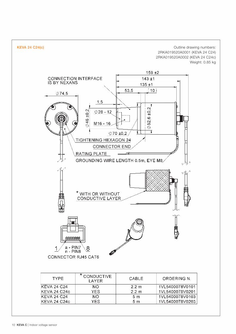
KEVA 24 C24(c) Outline drawing numbers: 2RKA019520A0001 (KEVA 24 C24)
2RKA019520A0002 (KEVA 24 C24c) Weight: 0.85 kg
KEVA C | Indoor voltage sensor 11
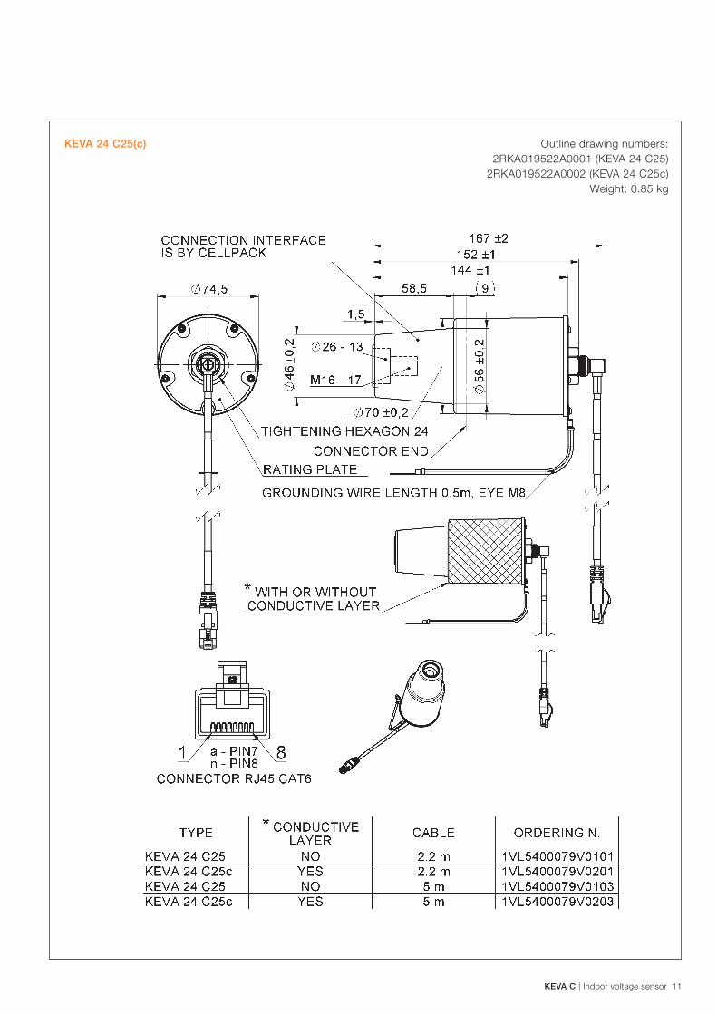
KEVA 24 C25(c) Outline drawing numbers: 2RKA019522A0001 (KEVA 24 C25)
2RKA019522A0002 (KEVA 24 C25c) Weight: 0.85 kg

12 KEVA C | Indoor voltage sensor
KEVA 24 C26(c) Outline drawing numbers: 2RKA019784A0001 (KEVA 24 C26)
2RKA019784A0002 (KEVA 24 C26c) Weight: 0.85 kg

KEVA C | Indoor voltage sensor 13
KEVA 24 C30 Outline drawing number: 2RKA020039A0001 (KEVA 24 C30)
Weight: 0.85 kg

Contact us
ABB s.r.o. EPMV Brno
Videnska 117, 619 00 Brno, Czech Republic Tel.: +420 547 152 082 +420 547 152 614 Fax: +420 547 152 626 E-mail: [email protected]
www.abb.com
1VLC
0007
17 R
ev.5
, en
201
7.05
.10
The data and illustrations are not binding. We reserve the right to make changes without notice in the course of technical develop-ment of the product.
© Copyright 2016 ABB. All rights reserved.