Embed Size (px)
Citation preview

Medium voltage products
UniSec Operation and maintenance manual
Safety 3 For your safety! 3 Skilled personnel 3 Critical messages 3 Contact us! 31. Introduction 4 1.1 General aspects 4 1.2 Operation and maintenance manual 4 1.3 Standards and specifi cations 4 1.4 Service conditions 42. Technical data 5 2.1 Electrical data 5 2.2 Internal arc classifi cation 53. Design and construction 6 3.1 Construction of the switchgear and main
components 6 3.2 Conception of the units and apparatus 6 3.3 Enclosure and partitioning 7 3.4 General information on interlocks 84. Operation of the switchgear 11 4.1 General warnings and precautions 11 4.2 Commissioning 11 4.3 Operating the switchgear 12 4.4 Opening the doors and covers 21 4.5 Voltage indicators 24 4.6 Pressure monitoring devices 25 4.7 GSec actuator device 265. Servicing and maintenance 31 5.1 General warnings and cautions 31 5.2 Maintenance intervals 31 5.3 Inspection 32 5.4 Servicing 32 5.5 Repairs 32 5.6 Replacing and mounting new equipment 33 5.7 Spare parts, auxiliary materials and lubricants 476. Troubleshooting 487. Recycling 49 7.1 General aspects 49 7.2 Materials 49A. Tightening torques for steel screws and nuts/bolts 50

2

3
WARNINGMake sure that the specified electrical ratings are not exceeded under switchgear operating conditions. Keep the manuals accessible to all personnel involved in installation, operation and maintenance. The user’s personnel must act responsibly in all matters affecting safety at work and correct handling of the switchgear.
Safety
WARNINGAlways follow the instructions in the manual and respect the rules of good engineering practice! Hazardous voltages can cause serious injury or death! Before proceeding with any work on this equipment, disconnect the power supply and earth live parts. Follow the safety regulations in force on the installation site.
Contact us!If you have any further questions about this manual, our field service team will be pleased to help. See the backside of this manual for contact information.
For your safety!• Strictly follow this manual.• Only install switchgear in indoor conditions suitable for elec-
trical equipment.• Ensure that installation, operation and maintenance is only
carried out by professional electricians.• Comply fully with the standards in force (IEC or local), the
connection conditions of the local power utility and the ap-plicable safety at work regulations.
• Observe the relevant information in the manual for all actions involving the switchgear.
• For use of the circuit-breaker, refer to the relative manual.
Skilled personnelAll the installation, commissioning, running and maintenance operations must be carried out by skilled personnel with in-depth knowledge of the apparatus.When carrying out maintenance work, the regulations in the country of installation must be strictly complied with.Maintenance work must only be performed in a professional way by trained personnel familiar with the characteristics of the switchgear, in accordance with all the relevant IEC safety regu-lations and those of other technical authorities, also complying with any further instructions of primary importance. It is recom-mended that ABB service personnel be called in to perform the servicing and repair work.
Critical messages Pay special attention to the information shown in the manual by the following symbol:
After this symbol there are four different explanations indicating what types of injuries or damage can be caused should the recommended precautions not be followed.
• DANGER - identifies the most serious and immediate hazards which cause serious personal injury or death
• WARNING - identifies hazards or unsafe practices which can result in serious personal injury or death
• CAUTION - identifies hazards or unsafe practices which can result in minor personal injury or product or property damage
• NOTE - identifies important procedures or requirements that, if not followed, can result in product or property damage

4
1. Summary1.4 Service conditions1.4.1 Normal service conditions
Normal service conditionsThe switchgear is designed for use in normal indoor service conditions as defined in the relevant IEC standards (see Table 1.). If the conditions deviate from the normal service conditions defined in the IEC standards (IEC 62271-1), this has to be agreed separately with the manufacturer.
Ambient air temperature °C
Maximum + 40
Maximum 24 h average + 35
Minimum 24 h average - 5(1)
Minimum recommended + 5
Altitude above sea level m
Maximum 1000
Conditions of humidity %
Average value of relative humidity (24 h) ≤ 95
Average value of relative humidity (1 month) ≤ 90
Pollution
The ambient air must not be significantly polluted by dust, smoke, corrosive and/or flammable gases, vapours or salt.
(1) Minimum celsius temperature minus 25 if the unit does not include a relay or a circuit-
breaker
Table 2. Service conditions
1.4.2 Special service conditions
Special service conditionsAt site altitudes above 1000 m, the effects of the reduction in dielectric strength of the insulating air must be taken into account (please refer to IEC standard 62271-100). Increased ambient temperatures must be compensated in the design of the busbars and branch conductors, as well as for the compo-nents, otherwise the current carrying capacity will be limited.
DANGERWhen the switchgear operate in areas with high humidity and/or major temperature fluctuations, there is a risk of dew deposits, which must remain an exception in normal service conditions for indoor switchgear. Preventive action (e.g. fitting electric heaters) must be taken into consideration with the manufacturer to avoid this condensation phenomenon and any resulting corrosion or other adverse effects. Control of the heaters depends on the relative project and details must be taken from the order documents.
1.1 General aspectsUniSec is indoor air insulated switchgear for medium voltage secondary distribution. It is the result of ABB’s quest for con-tinuous innovation, following a vision to meet ever-changing market needs.This new series of switchgear offers a wide range of technical and long-term solutions.Safety and reliability, user-friendliness, simple installation, as well as environmental sustainability were the driving forces in its development. UniSec is constructed by placing standardized units side by side in a coordinated way. Construction and testing are carried out in the factory.
1.2 Operation and maintenance manualThis manual provides information on operation and mainte-nance of UniSec units. It includes details about the units andservice conditions. Operation of the switchgear is illustrated in this manual and the instructions for replacing and mount-ing new apparatus are also given. To help you use UniSec, there is a troubleshooting chapter, with typical problems you might face when using the switchgear. The final chapter gives an example of product recycling. There is a separate instruc-tion manual for installation of the switchgear.
1.3 Standards and specifi cationsIEC Standards
IEC 62271-200 (ed. 1.0) High voltage switchgear and control gear - Part 200: A.C. metal-enclosed switchgear and con-trolgear for rated voltages above 1 kV and up to and including 52 kV
IEC 62271-1 (ed. 1.0) High voltage switchgear and control gear - Part 1: Common specifications
IEC 60044-1 (ed. 1.2) Instrument transformers - Part 1: Current trans-formers
IEC 60044-2 (ed. 1.2) Instrument transformers - Part 2: Inductive voltage transformers
IEC 62271-100 (ed. 2.0) High voltage switchgear and control gear - Part 100: Alternating current circuit-breakers
IEC 62271-102 (ed. 1.0) High voltage switchgear and control gear - Part 102: Alternating current disconnectors and earth-ing switches
IEC 60265-1 (ed. 3.0) High voltage switches - Part 1: Switches for rated voltages above 1 kV and less than 52 kV
IEC 62271-105 (ed. 1.0) High voltage switchgear and control gear - Part 105: Alternating current switch-fuse combinations
IEC 60529 (ed. 2.1) Degrees of protection provided by enclosures (IP Code)
IEC 61958 (ed. 1.0) High voltage prefabricated switchgear and control gear assemblies - Voltage presence indicating systems
Table 1. IEC Standards

5
2. Technical data2.1 Electrical data
Rated voltage Ur kV 12 17.5 24
Rated lightning impulse withstand voltage Up kV
Common value 75 95 125
Across open contacts 85 110 145
Rated test power frequency voltage Ud kV
Common value 28 38 50
Across open contacts 32 45 60
Rated frequency Hz 50/60 50/60 50/60
Rated current Ir A
Busbar 630/800/1250(1) 630/800/1250(1) 630
Feeder 630/800/1250(1) 630/800/1250(1) 630
Rated short-time withstand current kA
Main circuit 25 21/25(1) 21
Earthing circuit 25 21/25(1) 21
Rated duration of short-circuit s 2/3(1) 3/3(1) 3
Rated peak withstand current kA 63 52.5/63(1) 52.5
Degree of protection (IP-code)
For the enclosure IP 3X IP 3X IP 3X
For the partitions IP 2X IP 2X IP 2X
For the operating mechanism IP 3X IP 3X IP 3X
Mechanical endurance of switch-disconnector Cycles
Closed/Open 5000 5000 5000
Open/Earthed 1000 1000 1000
SF6 gas in switch-disconnector Busbar
Rated filling pressure 1.4 1.4 1.4
Minimum operating pressure 1.3 1.3 1.3
Amount of SF6 gas kg 0.25 0.25 0.25
(1) Only for panels with withdrawable circuit-breaker.
Table 3. Technical data
2.2 Internal arc classifi cationInternal arc fault withstand is defined as follows:
Current Accessible sides Arcing time
12.5 kA AFLR 1 s
16 kA AFLR 1 s
21 kA AFLR 1 s
25 kA(1) AFLR 1 s
(1) Only for panels with withdrawable circuit-breaker.
Table 4. Internal arc classification
NOTEFor data on additional equipment e.g. relays and circuit-breakers, check the manual for specific apparatus.
DANGERUniSec switchgear must be installed in closed rooms suitable for electrical equipment. This means that access must be restricted to authorized personnel only.

7
6
4
7
2
1
5
1
7
7
3
6
4
6
3. Design and construction
2. Switch-disconnector compartment
The three-position switch-disconnector is located between the main busbar and cable compartments. Its housing consists of a top half made of epoxy resin and a bottom half of stainless steel and is filled with SF6 gas, with the electrical parts of the switch-disconnector inside it.The bottom stainless steel part forms a metallic partition between the busbar and cable compartments. This partition makes the product safer by improving protection against contacts.
3.1 Construction of the switchgear and main components
General aspectsIn designing the UniSec unit, special attention was paid to increased reliability of use and improved personnel safety in the case of an arc fault.In order to improve personnel safety and maintenance work, the units are divided into separate compartments. The compartments are designed to withstand the very rapid rises in temperature and pressure caused by a possible arc fault condition.
3.2 Conception of the units and apparatus3.2.1 Compartments
UniSec is class LSC2A and LSC2B switchgear (for units with withdrawable circuit-breaker) according to the IEC62271-200 Standard.
Compartments The unit is divided into the following compartments:
1. Busbar compartment
The air-insulated busbar compartment is situated on the top of the unit and usually runs through the whole switchgear. A measuring or isolating unit placed in the middle of the
WARNINGWhen opening the busbar compartment, the user should take measures to ensure safe-ty (i.e. busbars must be de-energized and earthed).
WARNINGThis compartment is designated a “non-accessible compartment”. It must not be opened.
switchgear divides the main busbar compartment. Tools are required to open the busbar compartment. It is designated a “tool-based accessible compartment”.
Figure 1. Compartments

7
3.2.2 Service continuity
LSC Category For switchgear, the Loss of Service Continuity Category (LSC) describes the extent to which other compartments and/or functional units can remain energized when a main circuit compartment is opened. According to IEC 62271-200, the Loss of Service Continuity (LSC) of UniSec switchgear is LSC2A-PM and LSC2B-PM for the withdrawable circuit-breaker units. The PM denotes that the partitions between live parts and open compartments are metallic.
Compartment to be opened
Part of the switchgear that can be left energized
Cable corresponding to the functional unit
All other functional units
Fuse/Cable No Yes
Busbar Not relevant: not accessible Not relevant: not accessible
Circuit-breaker No Yes
Auxiliary circuits Yes Yes
Table 5.1. Access to the LSC2A unit (according to IEC 62271-200 Standard)
Compartment to be opened
Part of the switchgear that can be left energized
Apparatus compartment Cable compartment
Apparatus compartment
No Yes
Cable compartment
Yes No
Busbar compartment
Not relevant: not accessible Not relevant: not accessible
Auxiliary circuits Yes Yes
Table 5.2. Access to the LSC2B unit compartments (according to IEC 62271-200 Standard)
3.3 Enclosure and partitioningMaterial The enclosure and internal partitions of the units are made of 2 mm thick galvanised steel sheet. Doors and end platesare thoroughly cleaned and treated against corrosion before receiving a high quality coating of paint. The finishing coat is RAL 7035 colour (special colours by agreement). The doors of the cable compartments are pressure-resistant and are fitted with inspection windows. The auxiliary circuit compartment for secondary equipment is completely protected from the high voltage area thanks to the steel sheet partition.
Cable and circuit-breaker compartmentsThe high voltage compartment (circuit-breaker or cable compartment) is fitted with inspection windows. Neighbouring units are partitioned from one another by the side walls of each unit. The front of the unit is closed by a pressure-resistant removable door. On the sides of the end units, cover plates ensure a good appearance and are mechanically and thermally arc proof.
Ventilation openings Openings in the outer enclosure are needed for ventilating the extra heat, which may be generated in the busbars and branch connections. The pressure relief flaps form the ventilation openings for the units.
NOTEA separate exhaust duct at the rear of the switchgear is usually included.
3. Cable compartment
The cable compartment is reserved for the incoming/outgoing feeder cable connections, fuses, earthing switches or instru-ment transformers. In the units classified LSC2A/PM, the removable circuit-break-er (vacuum or gas) is housed on the left side of the cable com-partment.If the units are equipped with switch-disconnectors, there are interlocks to ensure that live parts inside are de-energized and earthed before opening. This compartment is then designated an “interlock-controlled accessible compartment”.If the units are not equipped with switch-disconnectors, the compartments are provided with padlocking facilities. This compartment is therefore designated as an “interlock-control-led accessible compartment”.
4. Apparatus compartment (only for units with withdrawable circuit-breaker)
The three-pole monoblocs are positioned in the apparatus compartment and house the fixed connection contacts of the circuit-breaker with the busbar and cable compartments.The shutters are of the metal type and are worked automatically during movement of the apparatus from the racked-out to the racked-in position and vice versa.The metal shutters allow metal partitioning between the busbar compartment and the cable compartment.
5. Control compartment
This compartment houses the switch-disconnector and earth-ing switch operating mechanisms, mechanical interlocks with position indicators, trip coils, voltage indicators and auxiliary contacts.
6. Auxiliary circuit compartment
The compartment contains either a basic or a large version depending on the application used. Secondary wiring, terminal blocks and relays are fitted in this compartment.
7. Pressure relief flaps
The pressure relief flaps on the back of the units direct the pressure waves and gases to optional arc ducts and filtersbehind the switchgear. This way, the risk of harm to the opera-tor due to an internal arc is minimized. The rear plate pf each unit has two arc pressure relief openings:• The upper gas relief flap is for the busbar and switching
compartment.• The lower gas relief flap is for the circuit-breaker and cable
compartment.

8
3.4 General information on interlocking The function of the interlocks is to prevent incorrect operations, guaranteeing the highest level of safety for both personnel and the plant.The interlocking function is also operational even if the doors of the cable compartment, operating mechanism compartment and apparatus compartment are open.
Purpose The purpose of the interlocking devices is to prevent incorrect operation of the switch-disconnector and earthing switch and thereby to ensure personnel safety. Interlocking is in operation even if the doors to the cable and control compartments are open.
Interlocking Interlocking includes:– Normal interlocking, which is fitted as standard on all the
units.– Additional interlocking devices, which are optional and to be
chosen by the customer.
Interlocking units for the LSC2A-PM units
PositionsSwitch-disconnector, switch-fuse combination units, and circuit-breaker units have two operating holes for the switch-disconnectors:– upper hole for the "open" and "closed" position– lower hole for the "earthed" position.
Interlock between the operating lever of the switch-disconnector and the motorThis is an electrical lock that prevents the motor from functioning when the operating lever is in the switch-disconnector seat.If a motor operator is installed, the spring is charged by a motor
operated by pushbuttons on the panel front. Insertion of the operating lever, which can only be performed in the open-closed positions, acts on a microswitch which cuts off the power supply to the motor, thereby preventing it from operating.
Locking devicesThe padlock prevents use of the operating handle in any posi-tion ("closed", "open" and "earthed").
Earthing switches Interlocking also applies to the earthing switches used to earth the bottom of the fuses and current transformers. These switches are mechanically connected to the operating device of the GSec switch-disconnector and work simultaneously with the GSec when it is operated between the "open" and "earthed" position.
Door openThe GSec switch-disconnector is locked in the "earthed" posi-tion until the door is closed.
Additional interlocking
Interlocks − For separate units, interlocking between the circuit-breaker
and the GSec can be arranged with key interlocks. − Interlocking can be checked with a microswitch when the
motor is activated. − Double key lock on the GSec switch-disconnector. Additional
locks, such as Ronis and Profalux, are also possible.
Table 6. shows different interlocks.
Interlock per type of unit
Unit Interlock
I1 I2 I3 I4
SDC, SDS • • •SFC, SFS, SBC, SBS •

9
Type I1 MV/LV/Transformers
Prevents earthing switch closing on a transformer protection unit unless the LV circuit-breaker is locked in the “open” or “isolated” position.
Prevents access to the transformer if the earthing switch for transformer protection has not been closed.
Type I2 Prevents earthing switch closing of a load-side unit unless the line-side switch is locked in the “open” position.
Type I3 Prevents simultaneous closing of two switches.
Type I4 Cross interlocking
Prevents an earthing switch closing if the switch of the other unit has not been locked in the “open” position.
Table 6. Key interlocks

10
Types of interlocks for withdrawable circuit-breaker LSC2B-PMs
Standard safety interlocks (compulsory)
Type Description Condition
1A Apparatus racking-in/out Apparatus in the "open" position
B Closing of the apparatus Truck in determinate position
2A Racking-in of the apparatus Multi-contact apparatus plug connected
B Removal of the apparatus multi-contact plug Truck in test position
3A Closing of the earthing switch Truck in test position
B Racking-in of the apparatus Earthing switch in the "open" position
4A Opening of the apparatus compartment door Truck in test position
B Apparatus racking-in Apparatus compartment door closed
5A Opening of the feeder compartment door Earthing switch in the "closed" position
B Opening of the earthing switch Feeder compartment door closed
Note: the apparatus is circuit-breakers and contactors.
Table 7.
Keys (on request)
1 Lock on apparatus racking-in Can only be removed if the truck is in the withdrawn position
2 Lock on earthing switch closing Can only be removed if the earthing switch is open
3 Lock on switch-disconnector opening Can only be removed if the earthing switch is closed
4 Insertion of the apparatus racking-in/out lever Can always be removed
5 Insertion of the earthing switch operating lever Can always be removed
Table 8.
Padlocks
1 Insertion of the apparatus racking-out/in lever
2 Shutter opening and closing
Table 9.
Locking magnet (on request)
1 Apparatus racking-in/out
2 Earthing switch opening and closing
3 Apparatus compartment door opening
Table 10.
Accessory devices
Shutter Fail-safe The device locks the shutters when the apparatus is removed from the compartment.The operator cannot open the shutters manually. The shutters can only be activated by the apparatus truck or by the service trucks.
Apparatus compatibility matrix - switchgear unit
The apparatus multi-contact plug and relative socket of the switchgear unit are fitted with a mechanical die, which makes apparatus racking-in into a switchgear unit with inappropriate rated current impossible.
Circuit-breaker mechanical operating mechanism
The apparatus compartment is fitted with a mechanical devices which makes it possible to operate closing and/or opening of the circuit-breakers directly by means of the front control pushbuttons, keeping the door closed.The commands can be given with the circuit-breakers in the service and withdrawn position.
Table 11.

11
4. Operation of the switchgear4.1 General warnings and precautions • Switch the auxiliary and control voltage on.
• Carry out testing operations on switching devices either manually or using electrical control, simultaneously observ-ing the relative position indicators.
• Check the mechanical and electrical interlocks for effective-ness, without using force.
• Check the SF6 gas pressure of the GSec switch-disconnec-tor and HD4 circuit-breaker (if available).
• Set the protective devices in the switchgear to the required values and check their operation with testing equipment.
• Instruct local operators regarding the basic features for cor-rect use of the switchgear.
• Check apparatus readiness for operation and the operating status of the electrical systems on the supply side and load side of the switchgear.
Other checkpoints Depending on the allocation of responsibilities, it may also be necessary to check the following equipment in the vicinity of the switchgear:• Power cables• Auxiliary cables• Auxiliary power source• Remote control system• Complete earthing system• Switchgear installation room equipment• Switchgear installation room characteristics:
− Pressure resistance in the case of an arc fault − Ventilation − Temperature − Humidity.
4.2.2 Start-up
Instructions
• Comply with all relevant safety regulations.
• Ensure that the switch-disconnectors and circuit-breakers in the system are in the OPEN position (4.3 Operating the switchgear).
• Remove any existing earthing and short-circuiting connec-tions in the critical operating area.
• Energize the power supply feeders.
• Connect the switchgear step by step, observing the signals and indicators.
• Where necessary, check that the conductors are in phase when there are several incoming feeder cables and switch-gear sections.
• Carry out all measurements and check that all functions that depend on the high voltage power supply are connected.
• Check there are no irregularities of any kind.
DANGERDo not walk on the top of switchgear units!
DANGERSwitchgear operations must be carried out with the doors closed.
WARNINGOperations and any type of work must be carried out by trained and specialized personnel who are familiar with the plant and follow all the safety regulations in accordance with the IEC Standards and other regulations in force, as well as any local work regulations and instructions.
4.2 Putting into service4.2.1 Preparatory work
Before connection to the medium voltage networkThe following work must be carried out in preparation for putting into service:
• Check the general condition of the switchgear for any dam-age or defects.
• Visually inspect the switching devices, isolating contacts, insulating parts, etc.
• Check the connection of the main earthing busbar to the installation earthing conductor (following the appropriate safety regulations).
• Check the paintwork for any damage and, where necessary, touch up as described in section 5.3.
• Remove all residues of materials, foreign objects and tools from the switchgear.
• Clean the switchgear, rubbing down insulating parts with a clean, dry, soft, non-fraying cloth. Remove any traces of greasy or sticky dirt as described in section 5.4.
• Correctly remount all covers etc. removed during assembly and testing procedures.
• Preparatory work for circuit-breakers: − Clean the insulating parts with a clean dry cloth. − Check that the upper and lower terminals are clean and
free from any deformation caused by shocks received during transport and storage.
− If the HD4 circuit-breaker is equipped with a pressure measuring device, it is advisable to check the SF6 gas pressure.
12
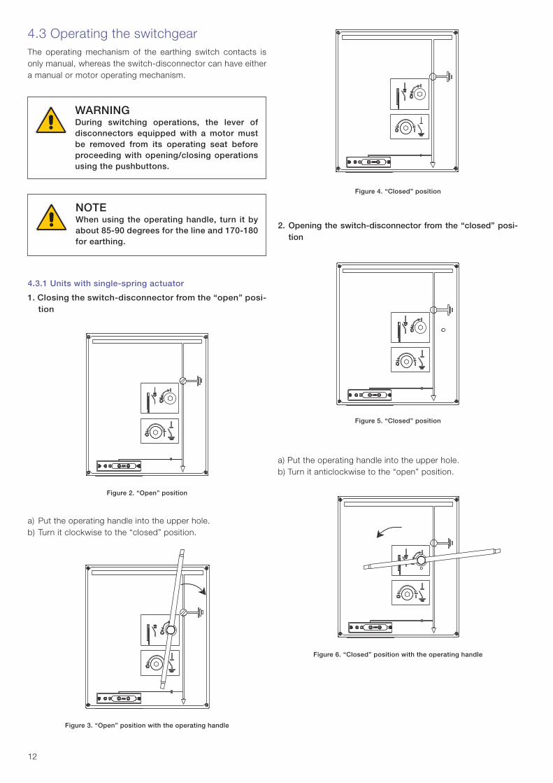
4.3.1 Units with single-spring actuator
1. Closing the switch-disconnector from the “open” posi-tion
Figure 2. “Open” position
a) Put the operating handle into the upper hole.b) Turn it clockwise to the “closed” position.
Figure 3. “Open” position with the operating handle
4.3 Operating the switchgearThe operating mechanism of the earthing switch contacts is only manual, whereas the switch-disconnector can have either a manual or motor operating mechanism.
Figure 4. “Closed” position
2. Opening the switch-disconnector from the “closed” posi-tion
Figure 5. “Closed” position
a) Put the operating handle into the upper hole.b) Turn it anticlockwise to the “open” position.
Figure 6. “Closed” position with the operating handle
NOTE When using the operating handle, turn it by about 85-90 degrees for the line and 170-180 for earthing.
WARNING During switching operations, the lever of disconnectors equipped with a motor must be removed from its operating seat before proceeding with opening/closing operations using the pushbuttons.

13
Figure 7. “Open” position
3. Operation from the “open” position to the “earthed” position
a) Put the operating handle into the lower hole.b) Turn the handle clockwise to the “earthed” position.
Figure 8. “Open” position with the operating handle in the lower hole
Figure 9. “Earthed” position
4. Opening the switch-disconnector from the “earthed” position
a) Close the cable compartment door.
Figure 10. “Earthed” position
b) Put the operating handle into the lower hole.c) Turn it anticlockwise to the “open” position.
Figure 11. “Earthed” position with the operating handle in the lower hole
Figure 12. “Open” position
NOTEIt is only possible to open the cable compartment door when only when the switch-disconnector is in the “earthed” position.
NOTEIn the SBR functional unit, the earthing switch and the line switch are inverted.
14
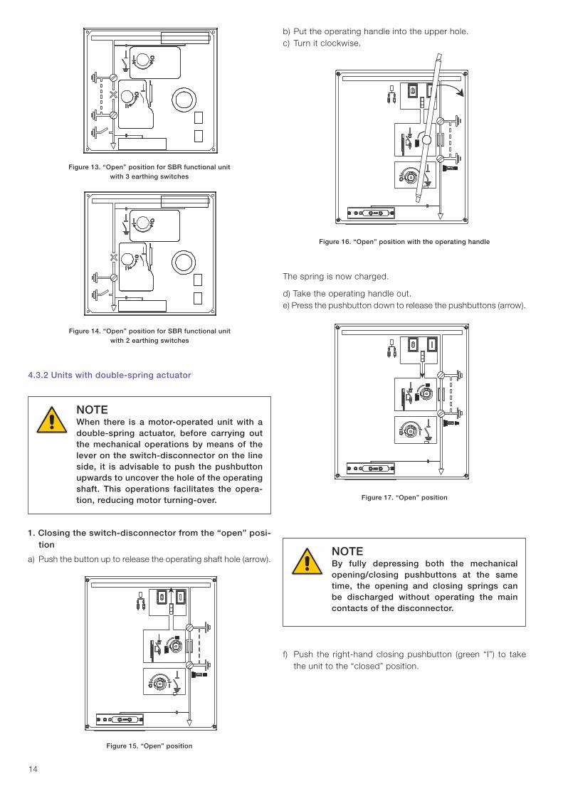
b) Put the operating handle into the upper hole.c) Turn it clockwise.
Figure 16. “Open” position with the operating handle
The spring is now charged.
d) Take the operating handle out.e) Press the pushbutton down to release the pushbuttons (arrow).
Figure 17. “Open” position
Figure 13. “Open” position for SBR functional unit with 3 earthing switches
Figure 14. “Open” position for SBR functional unit with 2 earthing switches
4.3.2 Units with double-spring actuator
NOTEWhen there is a motor-operated unit with a double-spring actuator, before carrying out the mechanical operations by means of the lever on the switch-disconnector on the line side, it is advisable to push the pushbutton upwards to uncover the hole of the operating shaft. This operations facilitates the opera-tion, reducing motor turning-over.
1. Closing the switch-disconnector from the “open” posi-tion
a) Push the button up to release the operating shaft hole (arrow).
Figure 15. “Open” position
NOTEBy fully depressing both the mechanical opening/closing pushbuttons at the same time, the opening and closing springs can be discharged without operating the main contacts of the disconnector.
f) Push the right-hand closing pushbutton (green “I”) to take the unit to the “closed” position.

15
Figure 18. “Closed” position
2. Opening the switch-disconnector from the “closed” posi-tion
a) Press the left-hand pushbutton (green “O”) to take the unit to the “open” position.
Figure 19. “Closed” position
Figure 20. “Open” position
3. Operating from the “earthed” to the “open” position
a) Put the operating handle into the lower hole.b) Turn the handle clockwise to the “earthed” position.
Figure 21. “Open” position with the operating handle in the lower hole
Figure 22. “Earthed” position
NOTEIt is only possible to open the cable compart-ment door when the switch-disconnector is in the “earthed” position.
4. Opening the switch-disconnector from the “earthed” position
a) Close the cable compartment door.b) “Earthed” position.
Figure 23. “Earthed” position
A
B
1
2
1
2
16
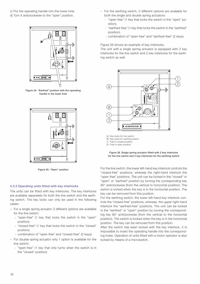
c) Put the operating handle into the lower hole.d) Turn it anticlockwise to the “open” position.
Figure 24. “Earthed” position with the operating handle in the lower hole
Figure 25. “Open” position
4.3.3 Operating units fitted with key interlocks
The units can be fitted with key interlocks. The key interlocks are available separately for both the line switch and the earth-ing switch. The key locks can only be used in the following cases:
– For a single spring actuator 3 different options are available for the line switch:- “open-free” (1 key that locks the switch in the “open”
position).- “closed-free” (1 key that locks the switch in the “closed”
position).- combination of “open-free” and “closed-free” (2 keys).
– For double spring actuator only 1 option is available for the line switch: - “open-free” (1 key that only turns when the switch is in
the “closed” position)
– For the earthing switch, 3 different options are available for both the single and double spring actuators: - “open-free” (1 key that locks the switch in the “open” po-
sition).- “earthed-free” (1 key that locks the switch in the “earthed”
position).- combination of “open-free” and “earthed-free” (2 keys).
Figure 26 shows an example of key interlocks. The unit with a single spring actuator is equipped with 2 key interlocks for the line switch and 2 key interlocks for the earth-ing switch as well.
A) Key locks for line switchB) Key locks for earthing switch1) Free in closed position2) Free in open position
Figure 26. Single spring actuator fitted with 2 key interlocks for the line switch and 2 key interlocks for the earthing switch
For the line switch, the lower left-hand key interlock controls the “closed-free” positions, whereas the right-hand interlock the “open-free” positions. The unit can be locked in the “closed” or “open” or “earthed” position by turning the corresponding key 90° anticlockwise (from the vertical to horizontal position). The switch is locked when the key is in the horizontal position. The key can be removed from this position.For the earthing switch, the lower left-hand key interlock con-trols the “closed-free” positions, whereas the upper right-hand interlock the “earthed-free” positions. The unit can be locked in the “earthed” or “open” position by turning the correspond-ing key 90° anticlockwise (from the vertical to the horizontal position). The switch is locked when the key is in the horizontal position. The key can be removed from this position.After the switch has been locked with the key interlock, it is impossible to insert the operating handle into the correspond-ing holes. Operation of units fitted with a motor operator is also locked by means of a microswitch.

17
4.3.5.1 Cable testing position
a) Open the plastic cover of the lower hole.b) Put the operating handle in the lower hole.c) Turn the handle anticlockwise to the “earthed” position
Figure 28. Earthed position
d) Open the cable compartment door.e) Remove the operating mechanism compartment cover (see
chapter 4.4.2).f) Push the locking plate into the upper position
Figure 29. Locking plate
g) Put the operating handle into the lower hole.h) Turn it clockwise to the “open” position.
Cable testing can now be carried out.After completing cable testing, carry out the above stages in reverse order.
Figure 27. Operating and signalling parts of the HD4 circuit-breaker
Operation sequences: earthing the unita) Open the circuit-breaker either electrically or mechanically
using the pushbutton.b) Open the GSec switch-disconnector.c) Close the earthing switches on both sides of the circuit-
breaker as instructed on the previous pages.
Operation sequences: connecting the unit to the networka) Open the earthing switches. b) Close the switch-disconnector.c) Close the circuit-breaker using the pushbutton.
4.3.5 Cable testing
4.3.4 Operations in switch-disconnector units
General aspects To achieve contact opening in accordance with the specified re-quirements, a 3-position switch-disconnector with an earthing switch is mounted between the busbar and the circuit-breaker. An additional earthing switch is connected to the lower side of the circuit-breaker (current transformers and MV cables). Both earthing switches are mechanically connected to the operat-ing mechanism and are operated simultaneously between the “open” and the “earthed” positions. Because the switch-dis-connector is capable of breaking currents under normal circuit conditions, there is no need for any mechanical interlocks be-tween the circuit-breaker and the switch-disconnector.
CAUTIONThe following interventions can only be carried out by professional electricians!
WARNINGCarry out the following interventions paying special attention to safety!
NOTEDuring the cable test, the earthing switch will be open when the cable compartment door is open.

1
2
3
11
712
654
15
14
13
10
9817 16
18
4.3.5.2 Cable testing procedure for SBR functional unit
a) Open the circuit breakerb) Open the switch-disconnectorc) Close the earth switchd) Open the cable compartment doore) Open the busbar compartment doorf) Bypass the busbar compartment door interlock; pull down
with a tool the metal interlock, in the busbar compartment over the mechanism
g) Open the earth switchh) Open the downside earth switch of the cable compartment
Figure 30. Busbar compartment door interlock for SBR
4.3.6 WBC and WBS type units
The WCB and WSB units can be fitted with Vmax series vac-uum circuit-breaker or with a VSC/P series vacuum contactor.
The apparatus, always in the withdrawable version, is mounted on a truck which allows the following positions in relation to the compartment:– RACKED-IN: main and auxiliary circuits connected; – ISOLATED: partially isolated with main circuits discon-
nected and auxiliary circuits connected (plug connector inserted); fully isolated with main and auxiliary circuits disconnected (plug connector removed);
– RACKED-OUT: main and auxiliary circuits disconnected and apparatus racked out of the switch-gear.
In the racked-in and isolated positions, the apparatus remains in the compartment with the door closed and its position can be seen through the switchgear inspection window. The front hooking-up crosspiece allows the racking-in/isolation operation, with the door closed, by means of the special operating lever.The apparatus is fitted with special locks, placed on the front crosspiece, which allow it to be hooked up into the corresponding joints of the compartment.A lock prevents the truck from advancing into the switchgear when the earthing switch is closed, whereas with the truck in the intermediate position between isolated and racked-in, a lock prevents circuit-breaker closing (both mechanical and electrical).On request, a locking magnet can be mounted on the truck which, if de-energized, prevents truck operation.The cord with the connector (plug) for connecting the auxiliary circuits to the instrument compartment, comes out of the upper part of the control box.The auxiliary circuit-breaker contacts and the truck racked-in and isolated contacts are available on-board the circuit-breaker. Some metal slides are fixed onto the sides of the apparatus for operating the partition shutter of the upper medium voltage contacts.
Caption
1 Lever for manually charging the closing spring2 Circuit-breaker open/closed indicator 3 Rating plate4 Opening pushbutton 5 Closing pushbutton6 Indicator for closing spring charged/discharged7 Operation counter8 Isolating contacts9 Slide for working the switchgear shutters
10 Truck11 Locks for hooking up into the fi xed part 12 Undervoltage release mechanical override (on request)13 Strikers for operating the contacts located in the enclosure 14 Connector (plug)15 Connector for cabling16 Circuit-breaker racking in/out operating lever17 Lock operating handles (11)
Figure 31.

1 2 3
19
3. Passing from the “isolated for test” to the “connected” position (with earthing switch open).
a) Close the circuit-breaker compartment door by pushing the handle downwards.
b) Tighten the knurled screws fully.c) Check that:
– the earthing switch locking magnet is energized (if pro-vided);
– the key locks are deactivated, if present.d) Insert the operating lever in the earthing switch seat, making
the ridge coincide with one of the two slots.e) Open the earthing switch by turning the operating lever
clockwise.f) Remove the operating lever from the earthing switch seat.
NOTEMake sure that the handles have snapped laterally (horizontal truck locks inserted in their seats).
2. Passing from the “isolated” to the “isolated for test” position (connection of the auxiliaries).
a) Insert and hook up the mobile connector in the fixed socket of the enclosure.
4.3.6.1 Operations for racking the apparatus into and out of the switchgear
NOTEWhen operations are carried out with the circuit-breaker racked out of the switchgear, pay great attention to the moving parts. The circuit-breaker must only be racked into the unit in the open position. Racking in and out must be gradual to avoid any shocks which might deform the mechanical interlocks.
1. Passing from circuit-breaker racked-out to the “isolated” position.
a) Move the truck close to the switchgear, insert the hooking up brackets and lock the wheels.
b) Release the circuit-breaker from the truck, moving the two handles at the same time towards the median axis of the circuit-breaker, at the same time progressively pushing the circuit-breaker by means of the handles towards the back of the switchgear until the circuit-breaker is locked with the two handles which snap sideways into the lateral guide slots.
c) Unlock the truck wheels, lift the hooking-up brackets and move the truck away from the switchgear.
Caption
1 Mobile connector
2 Fixed connector
3 Interlock
Figure 32.
NOTECheck that the compartment door is locked.
g) Close the shutter of the earthing switch operating seat by turning the small handle clockwise. This operation unlocks the circuit-breaker and a prevention lock on insertion of the operating lever into the earthing switch seat is activated.
h) Check that the locking magnet on the circuit-breaker truck is energized (if provided) and verify that the key lock on con-nection (if provided) is deactivated.
i) Insert the unlocking key, close the door and fully tighten the knurled screws.
j) Fully insert the circuit-breaker truck racking-in lever in its seat in the centre of the door and turn it clockwise until the circuit-breaker is fully connected.
k) Check that the circuit-breaker is connected through inspec-tion window.
4.3.6.2 Racking-out operation (only with circuit-breaker open)
1. Passing from the “connected” to the “isolated for test” position (with circuit-breaker open).
a) Through the inspection window, check that the circuit-breaker is open (indicator in position “O”).
b) Fully insert the circuit-breaker truck racking-in/out lever in its seat in the centre of the door and turn it (about 20 turns) anticlockwise until the circuit-breaker stops.
Figure 33.

3 1 4 5
52
6
7
20
c) Open the shutter of the earthing switch operating seat by turning the small actuator lever anticlockwise.
d) Insert the operating lever in the earthing switch seat, making the ridge coincide with one of the two slots.
e) Close the earthing switch by turning the operating lever clockwise.
f) Remove the operating lever from the earthing switch seat.g) Open the door by pulling the handle upwards.
2. Passing from the “isolated for test” to the “isolated” position (disconnection of the auxiliaries).
a) Release the mobile connector and remove it from the fixed socket of the enclosure.
3. Passing from the “isolated” to “racked-out” position.
a) Move the truck close to the switchgear.b) Insert the hooking up brackets and lock the truck wheels.c) Move the two handles at the same time towards the me-
dian axis of the circuit-breaker and at the same time pull the circuit-breaker, by means of the handles, towards the outside on the truck.
d) Leave the handle free and continue racking-out until the cir-cuit-breaker locks with the handles, which snap sideways locking the circuit-breaker on the truck.
e) Release the wheels, lift the hooking-up brackets and move the truck away from the switchgear.
4.3.6.3 Earthing switch operation
Check that the earthing switch key locks (if present) are deacti-vated. Check that the earthing switch electromechanical lock (if present) is energized. The earthing switch can only be operated with the circuit-breaker in the isolated or racked-out position and with the compartment door closed. Once started, the op-erations must always be completed.
Caption1 Key lock on open earthing switch 2 Key lock on closed earthing switch 3 Key lock on circuit-breaker racking in4 Small lever of the operating seat actuator5 Earthing switch operating seat6 Ridge on the lever7 Operating lever
Figure 34.
1. Closing
a) Check that the circuit-breaker is in the isolated or racked-out position.
b) Check that the door is closed, the knurled screws fully tight-ened and the handle completely closed.
c) Open the earthing switch operating seat shutter by turning the small lever of the operating mechanism actuator anti-clockwise, freeing the earthing switch operating seat.
Figure 35.
d) Insert the operating lever in the earthing switch seat, making the ridge coincide with one of the two slots.
e) Close the earthing switch by turning the operating lever clockwise.
f) Remove the operating lever.
2. Opening
a) Insert the operating lever in the earthing switch seat, mak-ing the ridge coincide with one of the two slots.
b) Open the earthing switch by turning the operating lever an-ticlockwise.
c) Remove the operating lever from the earthing switch seat.d) Close the earthing switch operating seat shutter by turning
the operating mechanism actuator clockwise. This operation releases the circuit-breaker and a prevention lock is acti-vated against insertion of the operating lever in the earthing switch.
Figure 36.
Control shaft shutter lever
Control shaft shutter lever

21
4.3.6.4 Operation sequence of the WBC and WBS units
NOTEOnce started, all the operations must be completed. The lever must be removed on completion of the operation. In the case of coupling with other units, which require interlocks, it is up to the customer to join the keys with a welded ring in order to ensure safety of the operation sequence.Before opening the door, check that the voltage indicators on the load side of the circuit-breaker are off and check the position of the apparatus through the inspection windows.
1. Circuit-breaker compartment
a) Through the inspection window, check that the circuit-breaker position indicator shows it is open "O".
b) Take the circuit-breaker to the isolated position.c) Loosen and fully unscrew the knurled screws.d) Open the circuit-breaker door.
This procedure can be carried out with service continuity (busbar compartment and cable energized).
2. Cable compartment
a) Through the inspection window, check that the circuit-breaker position indicator shows it is open "O".
b) Take the circuit-breaker to the isolated position.c) Check that the voltage indicators are off.d) Close the earthing switch (if present).e) Loosen and fully unscrew the knurled screws.f) Open the cable compartment door by pulling the handle
upwards.
3. Putting into service
a) Close the cable compartment door.b) Close the circuit-breaker compartment door and push the
handle downwards.c) Fully screw in the knurled screws.d) Close the circuit-breaker compartment door and push the
handle downwards. In the case of WCB and WSB, close the cable compartment door.
e) Open the earthing switch (if present).f) Take the circuit-breaker to the connected position.g) Close the circuit-breaker electrically or use the mechanical
pushbuttons on the panel (where requested).h) Through the inspection window, check that the circuit-
breaker is closed (indicator on "I").
4.4 Opening the doors and covers
NOTEThe cable compartment door can only be opened when the switch-disconnector is in the earthed position.
4.4.1 Cable compartment door
a) Lift the door handleb) Pull the door open
Figure 37. Opening the cable compartment door
Figure 38. Opening the cable compartment door

22
Figure 39. Control compartment door closed
4.4.3 Basic auxiliary circuits compartment door
a) Unscrew the screws on the right side of the compartmentb) Pull the door open
Figure 40. Basic auxiliary circuit compartment door closed
4.4.4 Large auxiliary circuits compartment door
a) Unscrew the screw on the right side of the compartment b) Pull the door open
Figure 41. Large auxiliary circuit compartment door closed
4.4.2 Control compartment cover
a) Unscrew the screws in the corners of the compartment b) Remove the cover
4.4.5 Incoming cable earthing procedure, according to CEI 0-16 standard
Earthing the incoming cables can be carried out in two ways:1. by applying mobile devices (insulating rod)2. by means of an earthing switch.
Cable earthing procedure using mobile devices (insulating rod)1. Request an intervention by the electricity supply company
to de-energize the connection cable and make it safe.2. Check that the voltage indicator, on the power distribution
side, does not indicate any presence of voltage in the incoming cables.
3. Isolate your plant, earth and short-circuit it to prevent any possibility of power supply to the circuit.
4. Make sure there is no voltage in the cable by using voltage indicator lamps.
5. Remove the fixing screws on the cover with the wording “Panel which can only be removed after intervention by the electricity supply company”.
6. Connect the mobile earthing cable located inside the cabinet.
7. Put a terminal of the mobile earthing device shown in the figure in the insulating rod seat.
Figure 42.
8. Using the insulating rod, connect the terminal of the earthing device to the earthing point on the power distribution side.
Make this connection starting from phase L3 (phase furthest inside).
Figure 43.

23
9. Repeat operations 7 and 8 for phases L2 and L1 as well. At this point the switchgear is safe and the maintenance work can be carried out.
10. On completion of the work, remove the mobile earthing device, following the above sequence in reverse order.
Procedure for earthing using an earthing switch1. Request an intervention by the electricity supply company
to de-energize the connection cable and make it safe.2. Take delivery of the key from the people in charge from the
electricity supply company, as a guarantee that the earth-ing switch of the power distribution delivery compartment has been closed.
3. Check that there is no voltage in the cable, by means of the voltage indicator lamps.
4. Insert the key, ringed with the electricity supply company key, in the special seat on the cable compartment cover, with the wording “Switch can only be operated after intervention by the electricity supply company” and free the operating seat of the earthing switch on the cable side.
5. Close the earthing switch on the cable side by acting on the operating shaft. At this point, the switchgear is made safe and the maintenance work can be carried out.
6. Unscrew the cable compartment door screw and lift the door to access the cable compartment.
7. To put the switchgear back into service, use the above sequence in reverse order.
4.4.6 Cable compartment door for the SBR unit
a) Ask the electricity supply company to isolate the connection cable and guarantee that it is in a safe condition.
b) Ensure that the (VPIS) voltage indicator in the lower part of the electricity supply company side does not indicate the presence of power in the incoming cable.
Figure 44. VPIS on lower side of the SBR unit
c) Open the circuit-breaker.d) Open the switch-disconnector.e) Open the interlock of the lower line isolator with the key.f) Pull the shutter lever of the lower earthing switch of the
cable compartment to the right.
Figure 45. Lower earthing switch
g) Close the lower earthing switch of the cable compartment.h) Open the second key interlock (accessory) in the top right
corner of the cable compartment cover.
Figure 46. Second key interlock
i) Break the sealing wire on the screw and then unscrew the screw of the cable compartment door.
Figure 47. Sealing wire
Figure 48. Sealing wire

24
Locking screw
NOTEThe indication of VPIS alone is not sufficient to prove that the system is de-energized: if the operating procedures require them, relevant voltage indicators according to IEC 61243-5 must be used.
The energized state of the unit is indicated by a flashing light with frequency of repetition of at least 1 Hz.
NOTEUnder very bright lighting it may be necessary to improve visibility by additional means.
l) Lift the cable compartment door and remove it.
Figure 49. Cable compartment door
4.4.7 Busbar compartment door for the SBR unit
a) Open the circuit-breaker.b) Open the switch-disconnector.c) Close the earthing switch.d) Lift and open the busbar compartment door.
Figure 50. Busbar compartment door for the SBR unit
4.4.8 Opening the cable compartment of the DRC and DRS unit
Make sure that the unit is not powered and earth the earthing switch.The door can be opened in the same way as the doors of the other units but only after the screw of the locking mechanism has been removed (fig. 51).
4.4.9 Opening the cable compartment of SDM and SDC units (750 mm)
Make sure that the unit is not powered and earth the earthing switch.These units are closed with two 375 mm doors, one of which closes the compartment with the switch-disconnector while the one alongside closes the cable compartment.The door of the cable compartment can be opened in the same way as the doors of the other units but only after the screw of the locking mechanism has been removed (fig. 51).
Figure 51. Opening the cable compartment
4.5 Voltage indicators UniSec units can be equipped with a voltage presence indicat-ing system in accordance with IEC 61958 (VPIS) or IEC 61243-5 (VDS).
4.5.1 Voltage indicators VPIS
VPIS indicators are used to indicate the presence of service medium voltage.

25
Operating temperature The VPIS will operate reliably over a temperature range of – 25° to + 50°C.
Phase comparison and testing of VPISEach phase of the integrated voltage presence indicating sys-tem has a connection point on the front panel, which can be used to perform phase comparison and to test the voltage presence indicator. Fujian Nanping Anda Electrical Manufacture Co. Ltd. product type DXN-HXQ-01 is recommended for phase comparison.
Threshold values for voltage presence indicationThe indication corresponding to “voltage present” appears when the actual line-to-earth voltage is between 45% of the nominal voltage and the rated voltage. The indication corre-sponding to “voltage present” does not appear when the actual line-to-earth voltage is less than 10% of the nominal voltage.
4.5.2 Voltage indicators VDS
VDS is used to detect the presence or absence of medium volt-age according to IEC 61243-5.The VDS are based on the HR system, the system consists of a fixed device, installed in the switchgear, coupled with amobile device to visually detect the presence or absence of service voltage and phase balance and on which the indicator lights are installed.The state of voltage present is visually indicated with at least 1 Hz repetition frequency. Flashing light indication whose impulse frequency must be between 1 Hz and 3 Hz with an impulse/pause ratio of 4 to 1.The "voltage indicators" which are recommended are the VM1 type used as a mobile device and VM3 type, used as a fixed and mobile device, made by Maxeta.The "voltage indicators" have a maximum operating voltage threshold of 90 V and a maximum current threshold of 2.5 µA at 50 Hz.
Operating temperature The VDS works reliably with a temperature range from –25 °C to + 50 °C.
Phase comparator The phase comparator detects the balance or unbalance of the phases between the interface and/or the test points. Detection is by means of an luminous indicator.The recommended phase comparator of the VDS is the PCM-HR type, made by Maxeta. It consists of a 1.4 m long test cable.
Threshold values for voltage indication When the line-earth voltage is between 45% and 120% of rated voltage, indication of "voltage present" must appear. The "voltage present" indication must not appear when the line-earth voltage is less than 10% of the rated voltage.
Figure 53.
4.6 Pressure monitoring devicesA device for monitoring the gas in the switch-disconnector can be installed on the front of the panel. The devices described below can be installed.
Temperature compensated pressure switch (Pressure reg-ulator)The device is self-powered and maintenance-free.The operator communicates with the device by means of two pushbuttons on the front.Pushbutton 1: Check: shows whether the display is functioning correctly;Pushbutton 2: Interrogates the monitoring device: the following information can be displayed:− OK: correct operating pressure;− Low: low pressure (minimum level for operation);− Very low: insufficient pressure (operation cannot be per-
formed).These indications can be displayed remotely by means of 2 contacts built into the device.
Figure 52.
Pressure gaugeThe device detects the measurement in temperature compen-sated zones and monitors the operating pressure of the gas in the switch-disconnector.The pressure gauge has 2 reference zones:− green: correct operating pressure;− red: insufficient pressure (operation cannot be performed).There is also a version with remote indications.

Ready
Alarm
Comm
Ready
Alarm
Comm
26
4.7 GSec actuator deviceThe “motor operating device” (MOD) or actuator device con-trols the spring charging motor and the coils (only for type 2 GSec switch-disconnector actuator (SD). The MOD is based on electronic circuits and includes protection and diagnostic functions, which improve the reliability, availability and safety of the system.The MOD includes a local operator panel interface (HMI) and binary inputs and outputs. The MOD also includes the logic and safety functions required for the disconnector operations.The protection functions include overcurrent for the coils and motor, over-temperature for the power driver and monitoring of the auxiliary power supply voltage.The diagnostic functions include supervision of the control circuits (for both the binary inputs), motor and coil continuity control and, finally, congruence of the position and state of the disconnector.The information regarding the state of the diagnostics and of the protections is made available locally by means of the HMI and remotely by the binary inputs and outputs.The following figure shows the GSec MOD functional block diagram. In this figure, the diagnostic and protection functional locks are highlighted in white.
2. Local operator panel (HMI)The following figure shows the local HMI which has 3 pushbut-tons and 5 LEDs.
Figure 55.
The opening and closing pushbuttons allow local motor opera-tion of the disconnector. The L/R pushbutton allows selection of the local or remote operating mode.The mode selected is indicated by two LEDs incorporated in the same pushbutton.When local mode is selected, the binary control inputs are disabled, whereas when the remote mode is selected the HMI opening and closing pushbuttons are disabled.The Ready and Alarm LEDs display the state of the protection and diagnostic functions. The Comm LED is reserved for future applications.
3. Binary inputsThe binary inputs include the opening and closing commands. The trip threshold is set to 85% of the rated voltage (in the case of a type 2 actuator, the trip threshold of the opening command is set to 70% of the rated voltage). The minimum impulse time needed for the command to be carried out is 300 ms. Please contact a sales representative for information about other settings available on request. The minimum time which can be set is 100 ms.Both the opening and closing inputs provide feedback on the state of the diagnostic and protection functions.When the disconnector is ready and is able to operate, the inputs allow circulation of a small current. On the other hand, in the case of a fault, their impedance becomes high, blocking current circulation. A “Trip Circuit Supervision” (TCS) type relay connected to one of these binary inputs produces an alarm in the case of a fault.Each binary input also includes a TCS and a self-diagnosis circuit. These functions allow any faults in the binary input circuits to be detected, among which: wire cut off, short-circuit and fault in the binary input circuitry. These functions are optional and require the use of two external resistances to be added to the control circuit. Please contact a sales representative to enable this function.
4. Binary outputsThree binary outputs are available: SD READY, FUSE, LOCAL. The SD READY contact is normally closed when no faults have been detected by the diagnostic and protection functions and the disconnector is ready to operate. When the contact is closed, it indicates that the whole disconnector is functioning correctly and can be operated. Every fault found by the diagnostic or protection functions makes this contact open.FUSE indicates the state of the disconnector fuse, for the applications where it is provided.LOCAL indicates that the MOD is in local operating mode. The state of this output changes following pressing of the HMI R/L key.
Figure 54.
1. Disconnector operation The GSec MOD carries out the disconnector opening and closing operations. The internal logic locks these operations when the disconnector is in the earthed position or when safe-ty conditions are not fulfilled. The safety conditions include: key locks, SF6 gas pressure and the state of the fuse.The position of the disconnector and the state of the safety conditions are acquired by microswitches connected to the MOD.The disconnector operations take place by means of a direct current motor, piloted by the MOD, which allows charging of the spring (or springs in the case of a type 2 actuator). In the case of type 2 actuator, the MOD pilots the coils to release the springs.
MOD Protection
andDiagnostics
Main controller
Power Driverprotection and
diagnostics
SDdiagnostics
Motor and release power
drives
Status and position sensors
Power Supply
TCS
SD Position State: Key – Manual SF6 PressureState of fuses
Bina
ry in
put
diag
nost
ics
FUSE
- L
OCAL
SD R
eady
OPEN
- C
LOSE
Motor Operating Device
Human-Machine Interface
27
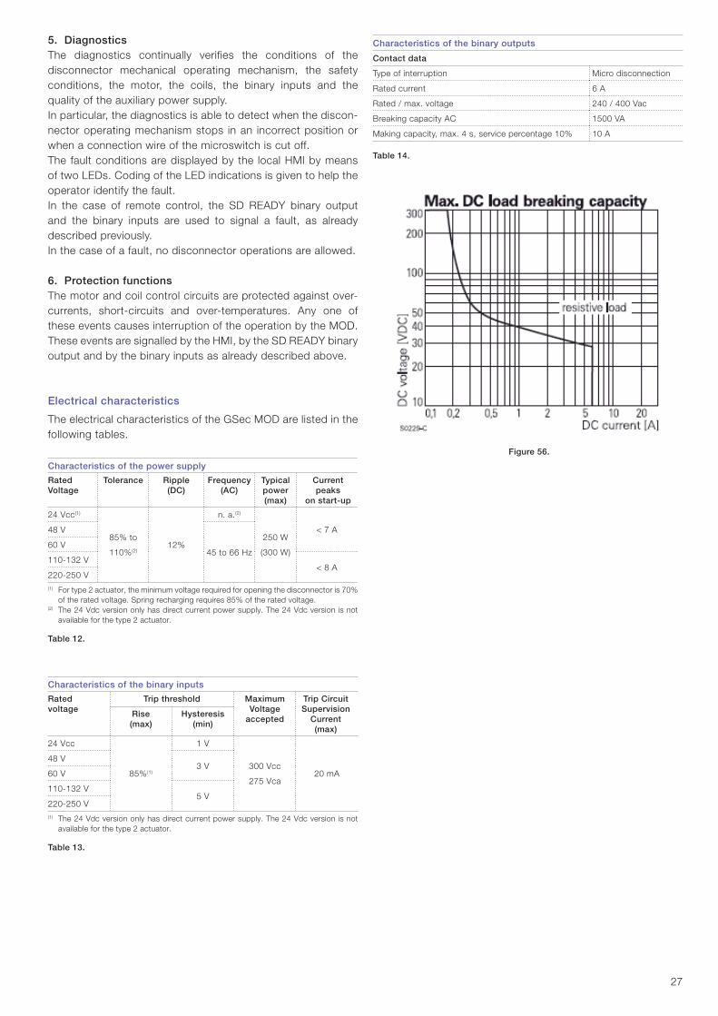
Characteristics of the binary outputs
Contact data
Type of interruption Micro disconnection
Rated current 6 A
Rated / max. voltage 240 / 400 Vac
Breaking capacity AC 1500 VA
Making capacity, max. 4 s, service percentage 10% 10 A
Table 14.
5. DiagnosticsThe diagnostics continually verifies the conditions of the disconnector mechanical operating mechanism, the safety conditions, the motor, the coils, the binary inputs and the quality of the auxiliary power supply.In particular, the diagnostics is able to detect when the discon-nector operating mechanism stops in an incorrect position or when a connection wire of the microswitch is cut off.The fault conditions are displayed by the local HMI by means of two LEDs. Coding of the LED indications is given to help the operator identify the fault.In the case of remote control, the SD READY binary output and the binary inputs are used to signal a fault, as already described previously.In the case of a fault, no disconnector operations are allowed.
6. Protection functionsThe motor and coil control circuits are protected against over-currents, short-circuits and over-temperatures. Any one of these events causes interruption of the operation by the MOD.These events are signalled by the HMI, by the SD READY binary output and by the binary inputs as already described above.
Electrical characteristics
The electrical characteristics of the GSec MOD are listed in the following tables.
Characteristics of the power supply
Rated Voltage
Tolerance Ripple (DC)
Frequency(AC)
Typicalpower(max)
Current peaks
on start-up
24 Vcc(1)
85% to
110%(2)12%
n. a.(2)
250 W
(300 W)
< 7 A48 V
45 to 66 Hz60 V
110-132 V< 8 A
220-250 V(1) For type 2 actuator, the minimum voltage required for opening the disconnector is 70%
of the rated voltage. Spring recharging requires 85% of the rated voltage.(2) The 24 Vdc version only has direct current power supply. The 24 Vdc version is not
available for the type 2 actuator.
Table 12.
Characteristics of the binary inputs
Rated voltage
Trip threshold MaximumVoltage
accepted
Trip Circuit Supervision
Current (max)
Rise (max)
Hysteresis (min)
24 Vcc
85%(1)
1 V
300 Vcc
275 Vca20 mA
48 V3 V
60 V
110-132 V5 V
220-250 V(1) The 24 Vdc version only has direct current power supply. The 24 Vdc version is not
available for the type 2 actuator.
Table 13.
Figure 56.

28
Local control of GSec using the HMI
The local HMI allows operation of the disconnector and display of the state of the diagnostics and protection functions.The table below shows how to use the HMI to operate the disconnector. In general, the disconnector can be operated when the Ready and L LEDs are lit up and the disconnector is not in the earthed position.
GSec operations using the HMI
LED Description
Ready
Alarm
Comm
The GSec disconnector is set to LOCAL mode.
All the HMI buttons are active:
allows the disconnector closing
allows disconnector opening
allows passing to REMOTE mode
Operation by means of binary inputs is disabled.
Ready
Alarm
Comm
Flashing
The GSec disconnector is set to REMOTE mode.
The flashing LED indicates that a command has not yet been received.
The opening and closing pushbuttons are not active.
allows passing to the LOCAL mode
The binary inputs for the opening and closing commands are active.
Ready
Alarm
Comm
Steady
The GSec disconnector is set to REMOTE mode.
The steadily lit-up LED indicates that a remote command has already been received.
The opening and closing pushbuttons are not active.
allows passing to LOCAL mode
The binary inputs of the opening and closing commands are active.
Table 15.

29
The following table lists the possible GSec MOD fault signals.
HMI – Fault signals
LED Type Description
Ready
AlarmREADY
GSec ready to operate
No fault found.
If the GSec is not in the earthed position, operating is possible.
Ready
Alarm Flashing EARTH
OP_DET
Return from earth (only for type 2 actuators)
Switch-disconnector has been opened from the “earthed” position and the motor is misaligned. It must be re-positioned by the operato.
To do this, press the HMI close key or transmit a close command via binary input.
Ready
Alarm Flashing
GSec
FAULT
Fault found in the GSec
Possible causes of this indication are:– GSec out of position– Fuse blown– Key lock inserted– Manual operation lock– Low SF6 pressure
The GSec cannot be operated.
Ready
AlarmWARNING
Temperature alarm
This alarm is produced when abnormal temperatures are detected inside the MOD.
The GSec cannot be operated.
Ready
Alarm Flashing
REC
FAULT
Recoverable fault
Possible causes of this indication are:– Power supply voltage outside tolerance– Overcurrent in the motor (1)
– Overcurrent in a coil (1)
– Over-temperature (1)
The GSec cannot be operated.(1) These conditions can occur during operation of the disconnector. In this case, the Ready LED turns off and the
Alarm LED fl ashes only once.
Ready
Alarm Steady
NONREC
FAULT
Non-recoverable fault
Possible causes of this indication are:– Motor short-circuited– Coil short-circuited– Motor cut out– Coil interrupted– Fault detected by the TCS inside the binary inputs (2)
When removing the cause of the fault, it is necessary to turn the power supply to the MOD off and then turn it on again to be able to re-start.
The GSec cannot be operated.(2) This condition can only occur when the internal TCSs are enabled and the MOD is in REMOTE mode.
The disconnector can be operated using the HMI by setting the MOD to LOCAL mode.
Table 16.

Ready
Alarm
Comm
OPEN
CLOSE
SD READY
Remote Control
Res
isto
r R
esis
tor
Ready
Alarm
Comm
OPEN
CLOSE
SD READY
TCS
TCS
4-wire remote control
30
Remote control of the GSec
The following diagrams show examples of remote control of the GSec. Both circuits allow any fault in the system to be identified.
Remote control with 6 wiresThe following figure shows Gsec connection for remote control us-ing just 6 wires. Other cables can be used to acquire further informa-tion (for example, the position of the disconnector directly from the auxiliary contacts, the LOCAL and FUSE binary outputs, etc.).This circuit uses the internal TCS function of the binary inputs. In
particular, this function requires the use of two external resistors connected in parallel with the remote control pushbuttons.This circuit allows any fault in the system to be found.In particular, the SD READY lamp turns off when one of the fol-lowing conditions occurs:– One of the 6 wires in interrupted– Any fault in the MOD– Any fault in the motor or in the coils– Any infringement of the disconnector safety conditions – Disconnector out of position (not ready for operation)– Any fault regarding the binary inputs including short-circuit
at the input connector.
Remote control with 4 wiresThe following figure shows the connection for remote control of the Gsec using just 4 wires. Other cables can be used to acquire fur-ther information (for example, the position of the disconnector, di-rectly from the auxiliary contacts, the LOCAL and FUSE binary out-puts, etc.). The internal TCS of the binary inputs are optional, but if enabled allow verification of op-eration of the binary inputs. In this case, the external resistances are not needed because they are replaced by the external TCS.This diagram works with the same performances even with just one external TCS, by replacing the other TCS with a simple resistance.This circuit allows any fault in the system to be found.In particular, the SD READY lamp turns off when one of the fol-lowing conditions occurs:– One of the 4 wires is interrupted– Any fault in the MOD– Any fault in the motor or in the coils– Any infringement of the disconnector safety conditions – Disconnector out of position (not ready for operation)– Any fault regarding the binary inputs including short-circuit
at the input connector (when the internal TCS are enabled).
Figure 57.
Figure 58.
MOD Protection
and Diagnostics
Main controller
Protection and diagnostics
control
IMSdiagnostics
Motor and release control
Status and position sensors
Power Supply
TCS
IMS Position State: Key – Manual SF6 pressureState of fuses
Diag
nost
ics
digi
tal i
nput
s
FUSE
- L
OCAL
IMS
Read
y
OPEN
ING-
CLOS
ING
Motor Operating Device
Human-Machine Interface

31
5.1 General warnings and cautions hand, for other parts, the length of the intervals may depend, for example, on the different modes of operation in individual cases, the degree of loading and environmental factors (includ-ing pollution and aggressive air).The time intervals for maintenance work to be carried out always depend on the operating conditions of the switchgear and, above all on the mode of operation, the number of rated and short-circuit current switching operations, ambient temperature, pollution, etc.The maintenance intervals and measures to be taken given in Table 13 are recommended for UniSec switchgear under normal service conditions. Three year intervals are recommended for all maintenance measures in more demanding conditions (such as areas with high pollution levels). The switch-disconnector 1- and 2-spring operating mechanisms are maintenance-free and do not need any lubrication.
Other important instruction manualsThe operation of all protection relays should be checked in accordance with the manufacturer’s instructions.
For circuit-breakers, refer to the following installation and serv-ice instructions:
Vacuum circuit-breaker: VD4/R type
1VDCD600565(VD4/R − VD4/L − VD4/UniAir − VD4/UniMix −12...24 kV − 630...1250 A − 12...25 kAInstallation and maintenance manual)
Vacuum circuit-breaker:Vmax type
1VCD600189(Vmax − 12...17.5 kV − 630...1250 A − 16...31.5 kAInstallation and maintenance manual)
SF6 circuit-breaker:HD4/R type
647021 (HD4 − 12-40.5 kV − 630-3600 A − 16-50 kAInstallation and maintenance manual)
Vacuum contactor:VSC type
600192(VSC − VSC/F − VSC/P − VSC/PN − VSC/PNG − 7.2/12 kV − 400 A Installation and maintenance manual)
Table 17. Circuit-breaker installation and maintenance instructions
Documentation If necessary, further details can be taken from the technical documentation for the switchgear installation (including, for ex-ample, any special operating conditions agreed on).
5.2 Maintenance intervalsWe recommend carrying out the maintenance work at the fol-lowing intervals:
Activityperformed
According tosection
Time intervalin years
According to number of switchingoperations
Inspection 5.3 5(2)
Maintenance 5.4 5(3) (4)
Repairs 5.5 As required As required
(2) Under more demanding service conditions, we recommend shortening this interval
appropriately. (3) According to the results of the inspection.(4) GSec
Electrical endurance: 100 breaking operations at 630A
5 short-circuit making operations
Mechanical endurance: 5000 no-load operations
Circuit-breakers: See the manuals
Earthing switch: 5 making operations − 1000 no-load operations
Table 18. Maintenance intervals
5. Service and maintenance
WARNINGPay attention to the following safety warnings:
Preparing the switchgear for safe assembly 1. For each case, set safe working conditions with the
utility safety officer.2. Make sure that national safety regulations are followed.3. Make sure there is no voltage in the busbars and cable
terminals and that the risk of reconnection is eliminated in all units. Any remote control must also be prevented.
4. Operate the switch (or the combination switch-fuse unit) into the "open" and then into the "earthed" position.
5. Make sure that auxiliary circuits are also disconnected from all possible power supply sources (including in-strument transformers).
Tools required• Screwdriver• Hand tools for 10 mm screws• M10 (M8) torque wrench• Hexagonal-head spanners 5, 6 and 8• Vacuum cleaner• Cleaning cloths• Mild alkaline cleaning agent
− Do not use trichloroethane, carbon carbotetrachloride or any kind of alcohol, etc. for cleaning
• Clean water• Silicone liquid
− In special cases, insulating surfaces can be covered with a thin layer of silicone liquid such as DC200/100CS or similar
• Instruction manuals• Test equipment.
Checkpoints• Check that there are no visible signs of, or damage from,
partial discharges• There should not be any visible signs of overheated connec-
tions • All components should perform perfectly and any faulty
components must be replaced.
Maintenance instructionsMaintenance serves for preserving trouble-free operation and achieving the longest possible working life of the switchgear.It comprises the following closely related activities:• Inspection: Determination of the actual conditions• Servicing: Measures to preserve the specified conditions• Repairs: Measures to restore the specified conditions.The inspection and servicing intervals for some of the appa-ratus/components (e.g. parts subject to wear) are determinedby fixed criteria, such as switching frequency, length of service and number of short-circuit breaking operations. On the other

32
5.3 InspectionGeneral aspectsWhere necessary, the working area must be isolated and secured against accidental re-connection before inspection, in accordance with the “Safety Regulations” specified by IEC standards and corresponding national standards. The switchgear condition must be monitored by regular inspections. Under normal operating conditions, inspections should be carried out once every four years by suitably trained professional electricians.
Instructions Carry out the following inspections:• Visually check for dirt, corrosion and moisture• Check for effects of high temperature on the main circuits• Check for traces of partial discharges on insulating material
parts• Check for traces of current leakage on insulating parts• Visually check the surfaces of the contact systems
− The contact points must be cleaned if signs of overheating (discoloured surface) are visible.
• Check the general condition and lubricate (Klüber NCA 52) the earthing switch contacts
• Check the operating pressure of the gas-insulated switching devices where possible.
The inspection must also include checking correct mechanical/electrical operation of the following switching devices• Actuators• Interlocking devices• Protection devices• Signalling devices• Switchgear accessories and auxiliary devices (e.g. storage
batteries)
5.4 ServicingInstructions If the need for servicing measures is established during the course of an inspection, proceed as follows:1. Tighten all electrical connections (main busbars, switches,
measuring devices, cables, etc.) to the correct torque, as-specified in the installation and tightening torque instruc-tions.
2. Clean all parts (disconnectors, circuit-breakers, tripping mechanisms, motors, etc.) with a vacuum cleaner and visu-ally inspect them. Clean the surfaces in general:• Lightly settled dry dust deposits: clean with a soft dry
cloth.• Wipe down after cleaning, using clean water and then dry
carefully.3. Perform a closing/opening operation on all disconnectors
and circuit-breakers, including the earthing switches.4. Connect the auxiliary control voltage, but ensure that no
remote signals can activate the components. Perform one electrical operation sequence on all motor-operated devices and tripping mechanisms.
5. Clean the busbar and cable compartments. Remove the switchgear unit roof and clean the GSec switch-disconnector insulation materials and busbars with a clean dry soft cloth. Remove all ingrained dirt, such as sticky or greasy stains using a cloth and a mild alkaline detergent. Wipe with a damp cloth using clean water and carefully dry the surface. Do the cleaning in the same way in the cable compartment (bottom of GSec switch-disconnector, instrument transformers, busbars and circuit-breaker).
6. If needed, clean and grease (Klüber NCA 52) the earthing switch contactor, blade and operating mechanism.
NOTEWith regard to the various switching devices, their own instruction manual should be followed.
No partial discharge must occur on the surfaces of equipment at the operating voltage. This can, for example, be detected by characteristic noises, a clearly perceptible smell of ozone, or visible glowing in the dark.
NOTEUnder abnormal operating conditions (in-cluding adverse climatic conditions) and/or particular environmental conditions (among which, heavy pollution and aggressive at-mosphere), inspection at shorter intervals may be necessary.
Repair measures If any irregular conditions are detected, appropriate servicing or repair measures must be taken.
NOTEShould partial discharges occur as a result of condensation, application of a thin silicone film over the surface concerned is often effective as a temporary remedy. It is advisable to ask the ABB after-sales service department for advice regarding permanent solutions to this uncommon type of problem.
5.5 Repairs5.5.1 Switchgear in general
Instructions • Carry out repair work immediately after a defect has been
discovered.• Completely remove all rust from damaged paintwork areas
on steel sheet and other steel parts by mechanical means, e.g. with a wire brush.
• Lightly roughen the surrounding paint and carefully degrease the entire surface. Then immediately apply an anti-rust prim-er and, after an appropriate hardening time, apply the top coat. Only use suitable and compatible paint products.
• Apply the top coat in the standard RAL 7035 colour, or the relevant special colour.

33
5.6 Replacing and mounting new appa-ratus
5.6.1 Replacing melted fuses
Investigating and clearing a fault The fuses cannot be regenerated. According to IEC Publication 60282-1, all three fuses must be replaced, even if only one or two of the them have blown. Exceptions are allowed when it is verified that the fuses have not been subjected to any overcurrent. If the fused switch-disconnector units (SFC, SFS or SFV) are equipped with a fuse tripping mechanism, the switch-disconnector opens automatically by means of the striker pin(s) of the fuse(s) and the tripping mechanism.
Figure 59. Position indicator
• Carefully remove any oxidation from galvanized surfaces: − For zinc surfaces use a wire brush or special cleaning
pad, e.g. Scotch-Brite, and remove any lightly settled particles with a dry, non-fraying cloth. Then treat the cleaned parts with zinc spray or zinc powder paint and, finally, with aluminium spray for colour matching.
− Passivate the surfaces of operating parts and any rust formation on phosphatised parts with a wire brush or metal-free cleaning pad, e.g. Scotch- Brite, and then clean with a dry cloth. Grease evenly (with Klüber NCA 52).
Instructions − Check that the colour of the fuse indicator is red and the
position indicator is in the "open" position. − Operate the switch to "earthed" position (see chapter 4.3
Operating the switchgear). − Open the door. − The upper and lower fuse holders are earthed and the fuses
can be removed and installed manually.
Removing the fuses
a) Start from phase L1 (near the door).b) Pull the fuse from its upper part until it is released.
Figure 60. Fuses installed
c) Lift the fuse upwards so that the lower part is also released.
Figure 61. Fuses dismantled
d) Carry out the same steps for the L2 and L3 phases.
CAUTION Follow the maintenance instructions in the manuals for the relative components.
• Check that the bolt connections at the contact points in the busbar system and the earth connections are tight, and that the contact system functions correctly.
• Where necessary, grease the slide plates and bearings in the unit again, or thoroughly clean them. Then grease them again with Klüber NCA 52 lubricant.
NOTETighten to the correct torque! The tighten-ing torques can be found at the end of the manual!

34
Installing the fuses
a) Start installation from phase L3 (the one furthest away from the door).
b) The fuse striker pin must be facing upwards. First of all, insert the lower part of the fuse in the bottom fuse holder.
Figure 62. Installing the fuses
c) Push the upper part into the top fuse holder.
Figure 63. Fuses installed (side)
d) Rotate the fuse until the arrow and technical data texts are pointing towards the door.
Figure 64. Fuses installed (front side)
e) Close the door. f) Operate the switch-disconnector to the "open" and then to
"closed" position (4.3 Operating the switchgear).
5.6.2.1 Mounting the circuit-breaker
Dismantling of the circuit-breaker
1. Before dismantling.
CAUTIONOperate the circuit-breaker and switch to the open position.Check that the cable is de-energized and close the earthing switches. Prevent any power supply from the cable.
Figure 65. Unit ready for circuit-breaker dismantling

35
2. Remove the front cover of the circuit-breaker.
a) Unscrew the two screws.
Figure 66. Front cover screws
3. Remove the internal cover plate.
a) Unscrew the three screws.
Figure 67. Inner cover screws
4. Unscrew the two screws from the lower part of the circuit-breaker.
Figure 68. Lower part screws
5. Remove the door. a) Open the door.b) Lift the door.
Figure 69. Removing the door
6. Remove the middle part in order to get more working space.
a) Unscrew the four screws on the front of the unit.b) Unscrew the two screws inside the unit.
Figure 70. Middle part screws
NOTEThe same screws are used for re-installation.
2 screws outside the unit
2 screws inside and 2 screws outside the unit

36
7. Disconnect the busbars from the lower switch-disconnector poles.
a) First of all, remove all the insulator caps first (only in the 24 kV unit) and then disconnect the busbars.
Figure 71. Removing the insulator caps
b) Unscrew the screws.
Figure 72. Disconnecting the busbars
8. Remove the circuit-breaker caps (only HD4 circuit-breaker).
a) Unscrew the screws.b) Remove the caps.
Figure 73. Removing the caps
9. Disconnect the busbars from the upper circuit-breaker poles.
a) Three upper poles of the circuit-breaker.
Figure 74. Removing the upper poles of the circuit-breaker
b) Unscrew the upper circuit-breaker screws and remove the part involved (only HD4 circuit-breaker).
Figure 75. Connections
10. Disconnect the busbars from the lower circuit-breaker poles.
a) Remove all the insulator caps, then unscrew the screws (only in the 24 kV unit).

37
1. Remove the lower busbars from the old circuit-breaker and install them in the new circuit-breaker.
Parts pcs Tightening torque (Nm)
Round-headed socket screw M10x25
6 40
Figure 79. Busbars installed in the circuit-breaker
2. Install the new circuit-breaker.
a) Slide the new circuit-breaker into the unit.
Figure 80. Installing the new circuit-breaker
Figure 76. Removing the 24kV unit insulator caps
b) Unscrew the screws.
Figure 77. Disconnecting the busbars
11. Take the circuit-breaker out of the unit.
Figure 78. Taking the circuit-breaker out of the unit
Installing a new circuit-breaker
NOTECorrect tightening torques.

38
3. Screw the two screws into the lower part of the circuit-breaker.
Parts pcs Tightening torque (Nm)
Hex. nuts with flange M6 2 9
Figure 81. Lower part screws
4. Connect the busbars to the lower circuit-breaker busbars.
a) Three poles.
Parts pcs Tightening torque (Nm)
Round-headed square neck bolts M10x30, conical spring washers D10, Hexagonal nut M10
3 40
Figure 82. Connecting the busbars
b) Install the insulator caps (only in the 24 kV unit).
Figure 83. Installing 24 kV unit insulator caps
5. Connect the busbars to the upper circuit-breaker poles.
a) Three upper poles of the circuit-breaker.
Figure 84. Installing the upper circuit-breaker poles

39
7. Connect the busbars to the lower switch-disconnector poles.
a) Connect the busbars.
Parts pcs Tightening torque (Nm)
Round-headed square neck bolts M12x35, conical spring washers D12, hexagonal nut M12-Steel 8
3 70
Figure 87. Connecting the busbars
b) Install the insulator caps (only in the 24 kV unit).
Figure 88. Installing the insulator caps
b) Insert the part involved (only HD4 circuit-breaker) and screw it up into the upper circuit-breaker.
Parts pcs Tightening torque (Nm)
Round-headed socket screw M8x25, Conical spring washers D8
6 30
Figure 85. Connection
6. Install the caps (only HD4 circuit-breaker).
Parts pcs
Nylon 8 mm 3
Figure 86. Installing the caps

40
10. Install the internal cover plate.
a) Screw in the three screws.
Parts pcs Tightening torque (Nm)
Cheese-head Torx plus screw M6x12
3 20
Figure 91. Internal cover screws
11. Install the front cover of the circuit-breaker.
a) Screw in the two screws.
Parts pcs Tightening torque (Nm)
Cheese-head Torx plus screw M6x12
2 20
Figure 92. Front cover screws
8. Install the middle part.
a) Screw the four screws into the front of the unit.b) Screw in the two screws inside the unit.
Parts pcs Tightening torque (Nm)
Cheese-head Torx plus screw M6x12
6 20
Figure 89. Middle part screws
9. Install the door.
Figure 90. Door installed

41
Figure 95. Circuit-breaker screw lock for the SBR unit
f) Lift and remove the circuit-breaker cover.
Figure 96. Circuit-breaker cover
12. Installation completed.
Figure 93. Circuit-breaker installed
5.6.2.2 Mounting the circuit-breaker for the SBR functional unit
Dismantling of the circuit-breaker
a) Open the circuit-breaker.b) Open the line switch-disconnector.c) Close the earthing switch.d) Open the busbar compartment door.e) On the left side of the busbar compartment, unscrew and
extract the L part.
Figure 94. Circuit-breaker screw lock for the SBR unit

42
g) Remove the 5 screws and the two metal sheet parts on the lower left side of the circuit-breaker.
Figure 97. Screwed metal sheets under circuit-breaker
h) Remove the 2 screws and the metal braking part at the bot-tom of the circuit-breaker.
Figure 98. Circuit-breaker braking system
Figure 99. Braking part of the circuit-breaker
i) Remove the circuit-breaker busbar screws.
Figure 100. Lateral circuit-breaker terminals
For circuit-breaker with K7 sensor:
Figure 101. Circuit-breaker terminals and K7 current sensors
j) Remove the screws at the top of the circuit-breaker poles.
Figure 102. Top circuit-breaker terminals

43
k) Remove the 3 busbars at the top of the circuit-breaker poles.
Figure 103. Circuit-breaker busbar connections
l) Disconnect the cable connectors and terminal blocks at the top of the circuit-breaker.
Figure 104. Circuit-breaker cable connector
m) Extract the circuit-breaker.
Figure 105. Circuit-breaker
Installing a new circuit-breaker
Figure 106. Circuit-breaker

44
Remove the circuit-breaker:
a) Insert the new circuit-breaker; for this operation there is a rail and a centring pin.
Figure 107. Circuit-breaker
Figure 108. Circuit-breaker rail and centring pin
b) Fix the circuit breaker-braking part with 2 screws.
Figure 109. Circuit-breaker braking system
Figure 110. Circuit-breaker braking part
c) Mount the 2 metal sheet parts on the lower and left side of the circuit-breaker, and screw them into the fixing point.
Figure 111. Metal sheets screwed in under circuit-breaker

45
f) Screw in the busbars on the right side of the circuit-breaker.
Figure 114. Circuit-breaker terminals and K7 current sensors
g) Tighten the screws on the circuit-breaker upper busbars.
Figure 115. Circuit-breaker busbar connections
h) Screw in the screws at the top of the circuit-breaker poles.
Figure 116. Upper circuit-breaker terminals
i) Close the busbar compartment door.
d) Mount the circuit-breaker cover.
Figure 112. Circuit-breaker cover
e) Insert and screw in the circuit-breaker cover locking part.
Figure 113. Circuit-breaker screw lock for the SBR unit

46
NOTEThe positions of the cables in the voltage indicator are named L1, L2 and L3 from left to right. The cables have a mark to indicate their correct position.
5.6.3.2 Mounting the lower voltage indicator for the SBR functional unit
a) Unscrew and remove the cover from the mechanism.
Figure 120. Mechanism cover
b) Unscrew and extract the voltage indicator module.
Figure 121. Voltage indicator module
5.6.3.1 Mounting the voltage indicator
Installing the voltage indicator
1. Cover.
a) Unscrew. b) Remove the cover of the control compartment.
Figure 117. Cover
2. Voltage indicator.
a) Unscrew the screws.
Figure 118. Screws in the front part of the voltage indicator
b) Unscrew the screws (the earthing wire is under the screw).
Figure 119. Screws behind the voltage indicator
c) Disconnect the cables.d) Installing a new voltage indicator: carry out the previous op-
erations in reverse order.

47
c) Open the cable compartment door. d) Disconnect the voltage indicator cables from the lower isola-
tors.
Lower connection of the VPIS signal cable
Figure 122. Isolator terminals for voltage indicator cable connections
e) Insert the new voltage indicator.f) Connect the voltage indicator cables.g) Mount the mechanism cover.
5.6.3.3 Mounting the upper voltage indicator for the SBR functional unit
a) Unscrew and remove the mechanism cover.b) Unscrew and extract the upper voltage indicator module.c) Open the busbar compartment door.d) Disconnect the voltage indicator cables from the lower
isolators.
Upper connection of the VPIS signal cable
Figure 123. Isolator terminals for voltage indicator cable connections
e) Insert the new voltage indicator.f) Connect the voltage indicator cables.g) Mount the mechanism cover.
5.7 Spare parts, auxiliary materials and lubricants
5.7.1 Spare parts
Available on requestA spare parts list for procurement of spare parts is available on request. This basically includes moving parts and parts subject to wear. When parts are required, the serial number of the rela-tive switchgear or switching device should always be indicated.
5.7.2 Auxiliary materials and lubricants
Lubricant Klüber NCA 52
Touching up paint Standard colour RAL 7035
Table 19. Lubricants and auxiliary materials.

48
6. TroubleshootingProblem Action to be taken
All unit types
Switch-disconnector cannot be closed. Check that the switch-disconnector is in the "open" position.
Turn the operating handle clockwise.
Switch-disconnector cannot be opened. Check that the switch is in the "closed" position.
Turn the operating handle anti-clockwise.
Switch-disconnector cannot be moved to the "earthed" position. Check that the switch is in the "open" position.
Turn the operating handle clockwise.
Check that the operating handle is connected in the earthing shaft.
Switch-disconnector cannot be moved from the "open" to the "earthed" position.
Check that the switch is in the "earthed" position.
Turn the operating handle anti-clockwise.
Check that the operating handle is connected to the earthing shaft.
Cable compartment door will not open or close. Check that the switch is in the "earthed" position.
Motor operated switch-disconnector
Switch-disconnector will not close or open. Check that the switch-disconnector is not in the "earthed" position.
Check that the auxiliary power supply is connected.
Combined switch-fuse unit
Switch-fuse will not close. Check to see if a fuse has blown.
Check that the handle is not in the operating hole.
Check that the locking part is in the down position.
The switch-fuse has not operated even though a fuse has blown. Check that the fuse is correctly fitted so that the trip pin indicator is pointing upwards.
Circuit-breaker unit
The cable compartment door will not open. Check that the switch-disconnector is in the "earthed" position.
Remove the key from the circuit-breaker before opening or closing the door.
The circuit-breaker will not close position. Make sure that the closing spring is fully charged, and that the interlocking coil is not energized.
Check that the circuit-breaker key is in place and turned to the correct operating position.
Check that the circuit-breaker auxiliary voltage plug is properly locked in the socket.
Instrument Transformers
Secondary measurements from the current transformers are not possible. Check that all short-circuiting connections on the secondary terminals of the current transformers have been removed.
Check the connections.
Table 20. Troubleshooting

49
7. Recycling7.1 GeneralThe instructions for recycling the UniSec product are given below. This includes materials used for the packing and for the product. It also includes handling instructions for when the product is taken out of service. The environmental regulations vary from country to country and frequently change. For this reason, it is recommended that lo-cal professionals be contacted about how to proceed when the product is taken out of service. Together with this document, information should also be given about returning the product after it has been taken out of serv-ice. Dealing with waste requires permission in most countries and you must get permission for your own company.ABB can give you more information, especially about SF6 gas. Please contact us if you have any questions.Information about local landfills can be obtained from the envi-ronmental agency. A product that is no longer in service can be dealt with in two alternatively ways. The product can be manu-ally demolished or crushed mechanically.Information about suitable facilities can be obtained from the local environmental agency.
NOTEAll parts containing hazardous waste must be removed and sent to a facility set up for this purpose.
NOTEIt is always necessary to act in accordance with the local legal requirements in force for disposal of the product.
7.2 MaterialsProduct materialsTable 21 gives examples of the SDC 375 unit materials and possible recycling methods:
Recycling capability
Material Recyclable kg %
Steel Yes 106.5 69
Stainless steel Yes 5.5 3.5
Copper Yes 14 9
Brass Yes <0.5 <0.5
Aluminium Yes 4 3
Zinc Yes 1.5 1
Plastics Yes 4.6 3
SF6 Yes <0.5 <0.5
Total recyclables 132 87
Rubber No <1 <0.5
Epoxy No 18.5 12
Total non-recyclables 19 13
Table 21. Product materials
SF6
SF6 is a fluorinated greenhouse gas covered by the Kyoto Pro-tocol and care must be taken not to cause emissions of SF6. At the end of its life, the greenhouse gas must be recovered. All operations must be carried out by skilled personnel with in-depth knowledge of SF6 gas.
NOTEFor information about SF6 gas and its relative management procedures, please consult the web page: http://www.abb.com/sf6

50
Nuts and bolts
Max. tightening torque [Nm]
Type Steel class 8.8
M4 3
M5 5
M6 9
M8 22
M10 45
M12 75
M16 185
Cheese-head hex. socket screws
Max. tightening torque [Nm]
Type Steel class 8.8
M4 2
M5 4
M6 8
M8 12
M10 35
M12 50
M16 110
Hex. socket-head and Torx round-head screws
Max. tightening torque [Nm]
Type Steel class 8.8 Steel class 10.9
M4 2 2
M5 4 4
M6 8 8
M8 12 12
M10 30
M12 60
A. Tightening torques for steel screws and nuts/bolts
Hexagonal-head bolts with flange
Max. tightening torque [Nm]
Type Steel class 90
M5 9
M6 16
M8 34
M10 58
M12 97
M16 215
Cheese-head Torx fastite screw
Max. tightening torque [Nm]
Type Steel class 8.8
M6 20
The values in the tables must be used unless the torque is specified in the table of joint types.

51
Joint type Tightening torque [Nm]
M5 M6 M8 M10 M12 M16
1 Bolts mounted on the CT, TPU types min 2.8 16 56
nominal
max 3.5 20 70
2 Bolts mounted on electrical pliers min 8
nominal 9
max 10
3 Cable connection nut min 18 35 65 170
nominal 20 40 70 180
max 22 45 75 190
4 Busbar connections min 18 35 65 170
nominal 20 40 70 180
max 22 45 75 190
5 Bolts mounted on the circuit-breaker min
nominal 30 40
max

52
Joint type Tightening torque [Nm]
M5 M6 M8 M10 M12 M16
6 Bolts mounted on the mandolino CT
min
nominal 35
max
7 Bolts mounted on the post insulator min 25
nominal 9 20 30
max 31
8 Bolts mounted on connection and transfer switch busbar
min 56
nominal 35 60
max 70
9 CT mounting bolts
min
nominal 40
max
10 GSec and busbar min
nominal 35
max


Your sales contact: www.abb.com/contacts More product information: www.abb.com/productguide
1VFM
2000
05 –
Rev
. G
, en
– O
per
atio
n m
anua
l – 2
011.
09 (U
niS
ec) (
mt)For more information please contact:
The data and illustrations are not binding. We reserve the right to make changes in the
course of technical development of the product.
© Copyright 2011 ABB.
All rights reserved.