Embed Size (px)
Citation preview
Medium voltage products
V-Contact VSC Installation and service instructions7.2/12 kV - 400 A
For your safety! 1
I. Introduction 2
II. Programme for environmental protection 2
III. Application of the standards for X-ray emission 3
IV. Safety information 3
V. Qualified personnel 3
VI. Interventions in the field 3
1. Description 4
1.1. “MAC” magnetic drive 4
1.2. Versions available 5
1.3. Characteristics 6
1.4. Weights and overall dimensions 6
1.5. Performances 8
1.6. Contactor auxiliary contacts 8
1.7. Compliance with Standards 9
1.8. Protection against short-circuit 9
2. Checking on receipt 10
3. Handling 11
3.1. Handling and lifting using a crane 12
4. Storage 13
5. Installation 14
5.1. General 14
5.2. Installation and operating conditions 14
5.3. Normal conditions 14
5.4. Special conditions 14
5.5. Overall dimensions 15
5.6. Assembly and making the connections 21
5.7. Description of the closing and opening operations 30
5.8. Manual emergency opening operation 33
6. Putting into service 34
6.1. General procedures 34
6.2. Racking the VSC/P contactor in and out 35
7. Maintenance 36
7.1. General 36
7.2. Handling the MAC-R2 electronic card 36
7.3. Inspection 37
7.4. Servicing 38
7.5. Servicing following a short-circuit or overload 38
7.6. Repairs 38
7.7. Instructions for dismantling or replacing fuses 39
7.8. Replacement of the contactor fuses 40
7.9. Mounting and dismantling the short-circuit busbar 43
7.10. Putting the contactor back into service 43
7.11. Checking the degree of vacuum of the interrupter 43
8. Spare parts and accessories 44
8.1. List of spare parts 44
9. Product quality and environmental protection 44
This instruction booklet refers to the following models:VSC/F-VSC/FN-VSC/P-VSC/PG-VSC/PN-VSC/PNGVSC-S/F-VSC-S/G-VSC-S/PG-VSC-S/PNG

1
For your safety!• Makesurethattheinstallationroom(spaces,divisionsand
ambient) is suitable for the electrical apparatus.• Checkthatalltheinstallation,puttingintoserviceand
maintenance operations are carried out by qualified personnel with suitable knowledge of the apparatus.
• Makesurethatthestandardandlegalprescriptionsarecompliedwithduringinstallation,operationandmaintenance,sothatinstallationsaccordingtotherulesof good working practice and safety in the work place are constructed.
• Strictlyfollowtheinformationgiveninthisinstructionmanual.
• Checkthattheratedperformanceoftheapparatusisnotexceeded during service.
• Checkthatthepersonneloperatingtheapparatushavethis instruction manual to hand as well as the necessary information for correct intervention.
• Payspecialattentiontothedangernotesindicatedinthemanual by the following symbol:
Responsible behaviour safeguards your own and others’ safety!
For any requests, please contact the ABB Assistance Service.
2
I. Introduction The instructions in this manual refer to the fixed and withdrawable versions of the VSC series of contactors. For correct use of the product,pleasereaditcarefully.
For the electrical and construction characteristics and the overall dimensionsoftheV-ContactVSCcontactors,pleasealsoseetechnical catalogue 1VCP000165.
Likealltheapparatuswemanufacture,theV-Contactvacuumcontactors are designed for different installation configurations. Furthermore,thisapparatusallowsfurthertechnicalandconstructionmodifications(atthecustomer’srequest)toadapttospecialinstallationrequirements.Consequently,thismanualmaynot provide information concerning special configurations of the apparatus.
Apartfromthismanual,itisthereforealwaysnecessarytoconsultthelatesttechnicaldocumentation(circuitandwiringdiagrams,assemblyandinstallationdrawings,anyprotectioncoordinationstudies,etc.),especiallyregardinganyvariantsrequestedinrelation to the standardised configurations.
Only use original spare parts for maintenance operations. The use of non-original spare parts can cause hazardous malfunctions and the apparatus warranty will no longer be valid.
Please refer to the technical sheets of the Kits for correct assembly of the accessories and/or spare parts. For further information,alsoseethe1VCP000165technicalcatalogueofthecontactor and the spare parts catalogue.
This manual and all the enclosed drawings must be considered an integral part of the apparatus. They must be easily to hand at all times for revision and reference.
Theseinstructionsdonotintendtocoverallthedetails,configurationsorvariantsoftheapparatus,storageorinstallation.Forthisreason,theinformationgivenbelowmaysometimes not contain the instructions regarding special configurations. This does not relieve the user from their responsibility for using good technical working practices inapplication,installation,serviceandmaintenanceoftheapparatuspurchased.Shouldfurtherinformationberequired,please contact ABB.
WARNING
Dangerous voltages. Risk of death, serious injury to people, damage to the apparatus or other objects.
Before carrying out any maintenance operations, turn the power supply off and earth the apparatus.
Read and understand this instruction manual before installation, service or maintenance of the apparatus.
Maintenance must only be carried out by skilled personnel.
The use of unauthorized spare parts for repairs to the apparatus, modification of the apparatus itself, or tampering by unskilled personnel creates hazardous conditions which may cause death or serious injury to people, or damage to the apparatus or other objects. Carefully follow all the safety instructions given in this manual.
II. Environmental protection programme
The V-Contact VSC vacuum contactors are manufactured inaccordancewiththeISO14000Standards(Guidelinesfor environmental management). The production processes are carried out in compliance with the Standards for environmental protection in terms of reduction in energy consumption as well as in raw materials and production of waste materials. All this is thanks to the medium voltage apparatus manufacturing facility environmental management system.
3
III. Application of the X-ray emission Standards
One of the physical properties of vacuum insulation is the possibility of X-ray emission when the interrupter contacts are open. The tests carried out at the PTB laboratories (Physikalisch-TechnischeBundesanstalt,inBrunswick-Germany) show that local emission at a distance of 10 cm fromtheinterrupterorpolesurface,doesnotexceed1 µSv/h. It follows that:– at the rated service voltage the use of vacuum interrupters
is absolutely safe;–applicationofthewithstandvoltageatpowerfrequency,accordingtotheIEC62271-1Standard,issafe;
– application of a voltage higher than the withstand voltage atpowerfrequencyorofadirectcurrenttestvoltage,specifiedintheIECStandard,cannotbeused;
–limitationoftheabove-mentionedlocalphenomena,oninterrupterswithopencontacts,dependsonkeepingthespecified distance between the contacts. This condition is intrinsically guaranteed by correct operation of the drive and by transmission system adjustments.
IV. Safety informationAlltheinstallation,puttingintoservice,runningandmaintenance operations must be carried out by suitably qualified personnel with in-depth knowledge of the apparatus.Make sure that the personnel working on the apparatus have this manual to hand and all the information required for correct intervention.Strictly follow the information given in this instruction manual.Makesurethatduringtheinstallation,serviceandmaintenance stages the standard and legal requirements for constructing the installations in accordance with the regulations for safety in the workplace are respected.Check that the rated performance of the apparatus is not exceeded during service.
V. Qualified personnel
Forthepurposesofthismanualandtheproductratingplates,a qualified person is intended as a person who:1) carefully reads the instruction manual all the way through.2)hasin-depthknowledgeoftheinstallation,construction
and service of the apparatus and knows about the risks connected with any interventions.
3)isqualifiedandauthorisedtoenergise,de-energise,earthand identify the circuits according to the safety procedures and the local regulations in force.
4) is qualified and authorised to put this apparatus into service,andtocarryoutmaintenanceandrepairoperationson it.
5)istrainedincorrectuseofprotectiveequipment,suchasrubbergloves,hardhats,protectivegoggles,faceshields,flameproofclothing,etc.accordingtothesafetyproceduresand the local regulations in force.
6) is trained in first-aid procedures.
VI. Interventions in the field
ABB can provide competent and well-trained personnel for assis-tance in the field to give technical guidance and consultancy regardinginstallation,fullservicing,repairandmaintenanceofapparatus.
4
1. DescriptionThe medium voltage V-Contact VSC contactors are pieces of apparatus suitable for operating in alternating current and are normally used to control users requiring a high number of hourly operations.
The basic contactors consist of:•mouldedpolyesterresinmonobloccontainingthevacuum
interrupters •bistableelectromagnetactuator•multi-voltagefeeders•auxiliarycontacts•mechanicalstatusindicator(open/closed)•manualemergencyopeningdevice.
Apartfromwhatisspecifiedforthefixedcontactors,thewithdrawable contactors also consist of: •fuseholderspresetforDINorBSfuses(accordingtothe
customer’srequirements)•automaticopeningdeviceforinterventionofevenasingle
fuse•truck•lockwhichpreventsclosingduringtheracking-in/out
operation.
The V-Contact VSC contactor introduces the drive with permanentmagnets-alreadywidelyused,experimentedand appreciated in medium voltage circuit-breakers - into the worldwide panorama of medium voltage contactors.The experience acquired by ABB in the field of medium voltage circuit-breakers fitted with drives with “MABS” permanentmagnets,hasmadeitpossibletodevelopanoptimisedversionoftheactuator(BistableMACdrive)formedium voltage contactors.
The drive is operated by means of an electronic feeder able to cover all the power supply voltages required by the major international Standards.
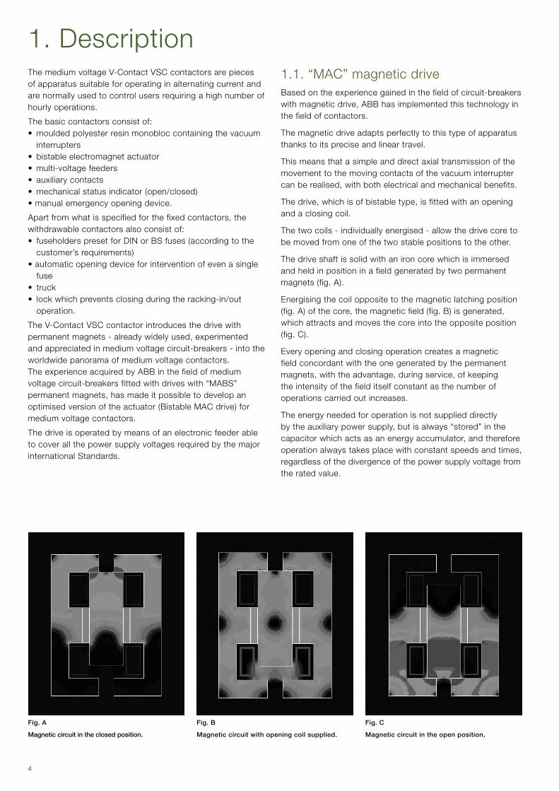
Fig. A
Magnetic circuit in the closed position.
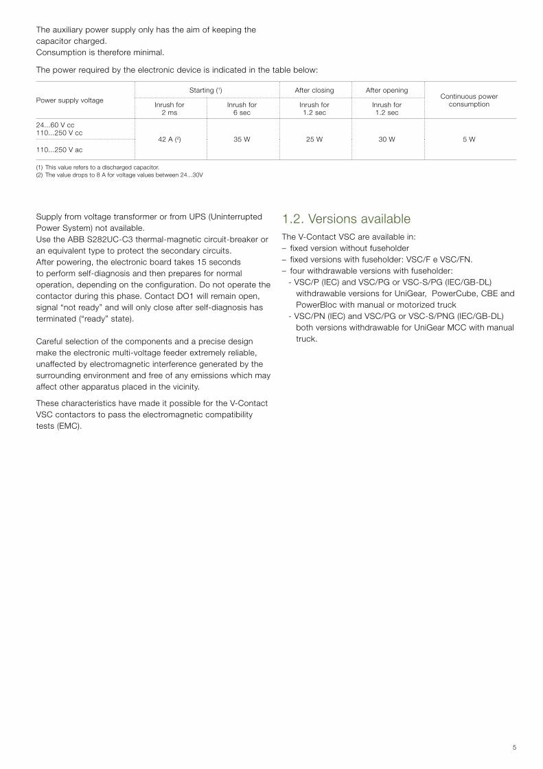
Fig. B
Magnetic circuit with opening coil supplied.
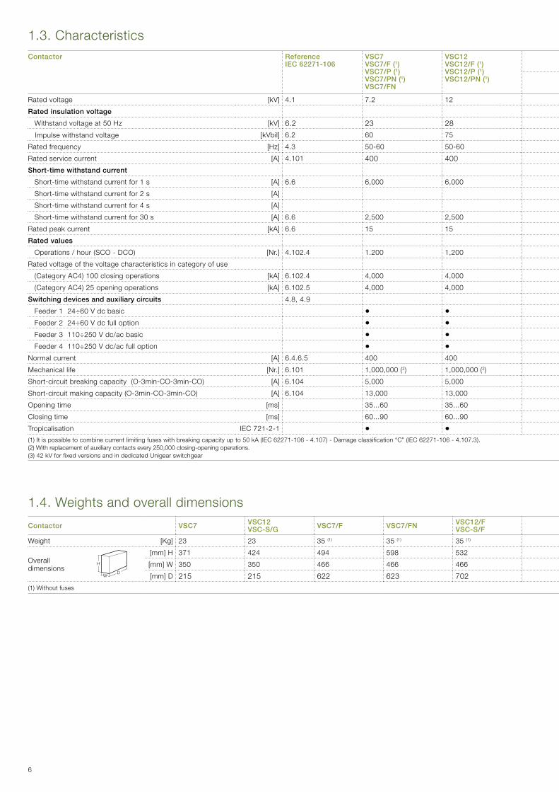
Fig. C
Magnetic circuit in the open position.
1.1. “MAC” magnetic driveBased on the experience gained in the field of circuit-breakers withmagneticdrive,ABBhasimplementedthistechnologyinthe field of contactors.
The magnetic drive adapts perfectly to this type of apparatus thanks to its precise and linear travel.
This means that a simple and direct axial transmission of the movement to the moving contacts of the vacuum interrupter canberealised,withbothelectricalandmechanicalbenefits.
Thedrive,whichisofbistabletype,isfittedwithanopeningand a closing coil.
The two coils - individually energised - allow the drive core to be moved from one of the two stable positions to the other.
The drive shaft is solid with an iron core which is immersed and held in position in a field generated by two permanent magnets(fig.A).
Energising the coil opposite to the magnetic latching position (fig.A)ofthecore,themagneticfield(fig.B)isgenerated,which attracts and moves the core into the opposite position (fig.C).
Every opening and closing operation creates a magnetic field concordant with the one generated by the permanent magnets,withtheadvantage,duringservice,ofkeepingthe intensity of the field itself constant as the number of operations carried out increases.
The energy needed for operation is not supplied directly bytheauxiliarypowersupply,butisalways“stored”inthecapacitorwhichactsasanenergyaccumulator,andthereforeoperationalwaystakesplacewithconstantspeedsandtimes,regardless of the divergence of the power supply voltage from the rated value.
5
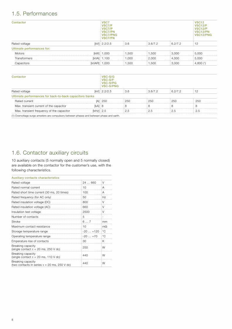
The auxiliary power supply only has the aim of keeping the capacitor charged. Consumption is therefore minimal.
The power required by the electronic device is indicated in the table below:
Power supply voltage Starting(1) After closing After opening
Continuous power consumptionInrush for
2 msInrush for
6 secInrush for1.2 sec
Inrush for1.2 sec
24...60 V cc110...250 V cc
42A(2) 35 W 25 W 30 W 5 W
110...250 V ac
SupplyfromvoltagetransformerorfromUPS(UninterruptedPower System) not available.Use the ABB S282UC-C3 thermal-magnetic circuit-breaker or an equivalent type to protect the secondary circuits.Afterpowering,theelectronicboardtakes15secondsto perform self-diagnosis and then prepares for normal operation,dependingontheconfiguration.Donotoperatethecontactorduringthisphase.ContactDO1willremainopen,signal “not ready” and will only close after self-diagnosis has terminated(“ready”state).
Careful selection of the components and a precise design maketheelectronicmulti-voltagefeederextremelyreliable,unaffected by electromagnetic interference generated by the surrounding environment and free of any emissions which may affect other apparatus placed in the vicinity.
These characteristics have made it possible for the V-Contact VSC contactors to pass the electromagnetic compatibility tests(EMC).
1.2. Versions availableThe V-Contact VSC are available in:– fixed version without fuseholder– fixed versions with fuseholder: VSC/F e VSC/FN.– four withdrawable versions with fuseholder: -VSC/P(IEC)andVSC/PGorVSC-S/PG(IEC/GB-DL)
withdrawableversionsforUniGear,PowerCube,CBEandPowerBloc with manual or motorized truck
-VSC/PN(IEC)andVSC/PGorVSC-S/PNG(IEC/GB-DL)both versions withdrawable for UniGear MCC with manual truck.
(1)Thisvaluereferstoadischargedcapacitor.(2)Thevaluedropsto8Aforvoltagevaluesbetween24...30V
6
1.4. Weights and overall dimensions
Contactor VSC7 VSC12VSC-S/G VSC7/F VSC7/FN VSC12/F
VSC-S/F VSC7/P VSC12/P - VSC12/PGVSC-S/PG VSC7/PN VSC7/PNG VSC12/PN VSC12/PNG
VSC-S/PNG
Weight [Kg] 23 23 35 (1) 35 (1) 35 (1) 52 (1) 52 (1) 45 (1) 45 (1) 45 (1) 45 (1)
Overall dimensions
[mm] H 371 424 494 598 532 636 636 653 653 653 653
[mm] W 350 350 466 466 466 531 531 350 350 350 350
[mm] D 215 215 622 623 702 657 657 673 673 673 673
(1)Withoutfuses
H
DW
1.3. Characteristics Contactor
ReferenceIEC 62271-106
VSC7 VSC7/F (1) VSC7/P (1)VSC7/PN (1)VSC7/FN
VSC12 VSC12/F (1) VSC12/P (1)VSC12/PN (1)
Reference VSC7/PNG (1) VSC12/PNG (1) VSC-S/G VSC-S/F (1) VSC-S/PG (1) VSC-S/PNG (1)GB/T
14808-2001DL/T 593-2006
Rated voltage [kV] 4.1 7.2 12 4.1 7.2 12 12
Rated insulation voltage
Withstand voltage at 50 Hz [kV] 6.2 23 28 6.2 • 32 42 28(3)
Impulse withstand voltage [kVbil] 6.2 60 75 6.2 60 75 75
Rated frequency [Hz] 4.3 50-60 50-60 4.3 50-60 50-60 50-60
Rated service current [A] 4.101 400 400 4.101 400 400 250
Short-time withstand current
Short-time withstand current for 1 s [A] 6.6 6,000 6,000 6,000 600
Short-time withstand current for 2 s [A] 6.6 4,000 4,000
Short-time withstand current for 4 s [A] • 4,000 4,000
Short-time withstand current for 30 s [A] 6.6 2,500 2,500 6.6 2,500 2,500 2,500
Rated peak current [kA] 6.6 15 15 6.6 15 15 15
Rated values
Operations/hour(SCO-DCO) [Nr.] 4.102.4 1.200 1,200 4.102.2 1,200 1,200 1,200
Rated voltage of the voltage characteristics in category of use
(CategoryAC4)100closingoperations [kA] 6.102.4 4,000 4,000 6.102.4 4,000 4,000
(CategoryAC4)25openingoperations [kA] 6.102.5 4,000 4,000 6.102.5 4,000 4,000
Switching devices and auxiliary circuits 4.8,4.9 4.8,4.9
Feeder 1 24÷60 V dc basic • • • • • Feeder 2 24÷60 V dc full option • • • • • Feeder 3 110÷250 V dc/ac basic • • • • • Feeder 4 110÷250 V dc/ac full option • • • • •Normal current [A] 6.4.6.5 400 400 6.4,6.5 400 400 400
Mechanical life [Nr.] 6.101 1,000,000(2) 1,000,000(2) 6.101 1,000,000(2) 1,000,000(2) 200,000
Short-circuitbreakingcapacity(O-3min-CO-3min-CO) [A] 6.104 5,000 5,000 6.104 5,000 5,000 -
Short-circuitmakingcapacity(O-3min-CO-3min-CO) [A] 6.104 13,000 13,000 6.104 13,000 13,000 -
Opening time [ms] 35...60 35...60 35...60 35...60 35...60
Closing time [ms] 60...90 60...90 60...90 60...90 60...90
Tropicalisation IEC 721-2-1 • • • • • •(1)Itispossibletocombinecurrentlimitingfuseswithbreakingcapacityupto50kA(IEC62271-106-4.107)-Damageclassification“C”(IEC62271-106-4.107.3).(2)Withreplacementofauxiliarycontactsevery250,000closing-openingoperations.(3)42kVforfixedversionsandindedicatedUnigearswitchgear

7
1.4. Weights and overall dimensions
Contactor VSC7 VSC12VSC-S/G VSC7/F VSC7/FN VSC12/F
VSC-S/F VSC7/P VSC12/P - VSC12/PGVSC-S/PG VSC7/PN VSC7/PNG VSC12/PN VSC12/PNG
VSC-S/PNG
Weight [Kg] 23 23 35 (1) 35 (1) 35 (1) 52 (1) 52 (1) 45 (1) 45 (1) 45 (1) 45 (1)
Overall dimensions
[mm] H 371 424 494 598 532 636 636 653 653 653 653
[mm] W 350 350 466 466 466 531 531 350 350 350 350
[mm] D 215 215 622 623 702 657 657 673 673 673 673
(1)Withoutfuses
1.3. Characteristics Contactor
ReferenceIEC 62271-106
VSC7 VSC7/F (1) VSC7/P (1)VSC7/PN (1)VSC7/FN
VSC12 VSC12/F (1) VSC12/P (1)VSC12/PN (1)
Reference VSC7/PNG (1) VSC12/PNG (1) VSC-S/G VSC-S/F (1) VSC-S/PG (1) VSC-S/PNG (1)GB/T
14808-2001DL/T 593-2006
Rated voltage [kV] 4.1 7.2 12 4.1 7.2 12 12
Rated insulation voltage
Withstand voltage at 50 Hz [kV] 6.2 23 28 6.2 • 32 42 28(3)
Impulse withstand voltage [kVbil] 6.2 60 75 6.2 60 75 75
Rated frequency [Hz] 4.3 50-60 50-60 4.3 50-60 50-60 50-60
Rated service current [A] 4.101 400 400 4.101 400 400 250
Short-time withstand current
Short-time withstand current for 1 s [A] 6.6 6,000 6,000 6,000 600
Short-time withstand current for 2 s [A] 6.6 4,000 4,000
Short-time withstand current for 4 s [A] • 4,000 4,000
Short-time withstand current for 30 s [A] 6.6 2,500 2,500 6.6 2,500 2,500 2,500
Rated peak current [kA] 6.6 15 15 6.6 15 15 15
Rated values
Operations/hour(SCO-DCO) [Nr.] 4.102.4 1.200 1,200 4.102.2 1,200 1,200 1,200
Rated voltage of the voltage characteristics in category of use
(CategoryAC4)100closingoperations [kA] 6.102.4 4,000 4,000 6.102.4 4,000 4,000
(CategoryAC4)25openingoperations [kA] 6.102.5 4,000 4,000 6.102.5 4,000 4,000
Switching devices and auxiliary circuits 4.8,4.9 4.8,4.9
Feeder 1 24÷60 V dc basic • • • • • Feeder 2 24÷60 V dc full option • • • • • Feeder 3 110÷250 V dc/ac basic • • • • • Feeder 4 110÷250 V dc/ac full option • • • • •Normal current [A] 6.4.6.5 400 400 6.4,6.5 400 400 400
Mechanical life [Nr.] 6.101 1,000,000(2) 1,000,000(2) 6.101 1,000,000(2) 1,000,000(2) 200,000
Short-circuitbreakingcapacity(O-3min-CO-3min-CO) [A] 6.104 5,000 5,000 6.104 5,000 5,000 -
Short-circuitmakingcapacity(O-3min-CO-3min-CO) [A] 6.104 13,000 13,000 6.104 13,000 13,000 -
Opening time [ms] 35...60 35...60 35...60 35...60 35...60
Closing time [ms] 60...90 60...90 60...90 60...90 60...90
Tropicalisation IEC 721-2-1 • • • • • •(1)Itispossibletocombinecurrentlimitingfuseswithbreakingcapacityupto50kA(IEC62271-106-4.107)-Damageclassification“C”(IEC62271-106-4.107.3).(2)Withreplacementofauxiliarycontactsevery250,000closing-openingoperations.(3)42kVforfixedversionsandindedicatedUnigearswitchgear
8
1.6. Contactor auxiliary circuits10auxiliarycontacts(5normallyopenand5normallyclosed)areavailableonthecontactorforthecustomer’suse,withthefollowing characteristics.
Auxiliary contacts characteristics
Rated voltage 24 … 660 V
Rated normal current 10 A
Ratedshorttimecurrent(30ms,20times) 100 A
Ratedfrequency(forAConly) 50 Hz
Ratedinsulationvoltage(DC) 800 V
Ratedinsulationvoltage(AC) 660 V
Insulation test voltage 2500 V
Number of contacts 5 -
Stroke 6 … 7 mm
Maximum contact resistance 10 mΩ
Storage temperature range -20 … +120 °C
Operating temperature range -20 … +70 °C
Emperature rise of contacts 30 K
Breaking capacity (singlecontactτ=20ms,250Vdc) 250 W
Breaking capacity (singlecontactτ=20ms,110Vdc) 440 W
Breaking capacity (twocontactsinseriesτ=20ms,250Vdc) 440 W
1.5. Performances Contactor VSC7
VSC7/FVSC7/PVSC7/PNVSC7/PNGVSC7/FN
VSC12VSC12/FVSC12/PVSC12/PNVSC12/PNG
Rated voltage [kV] 2.2/2.5 3.6 3.6/7.2 6.2/7.2 12
Ultimate performances for:
Motors [kW] 1,000 1,500 1,500 3,000 5,000
Transformers [kVA] 1,100 1,000 2,000 4,000 5,000
Capacitors [kVAR] 1,000 1,500 1,500 3,000 4,800(1)
Contactor VSC-S/GVSC-S/FVSC-S/PG VSC-S/PNG
Rated voltage [kV] 2.2/2.5 3.6 3.6/7.2 6.2/7.2 12
Ultimate performances for back-to-back capacitors banks
Rated current [A] 250 250 250 250 250
Max. transient current of the capacitor [kA] 8 8 8 8 8
Max. transient frequency of the capacitor [kHz] 2.5 2.5 2.5 2.5 2.5
(1)Overvoltagesurgearrestersarecompulsorybetweenphasesandbetweenphaseandearth.
9
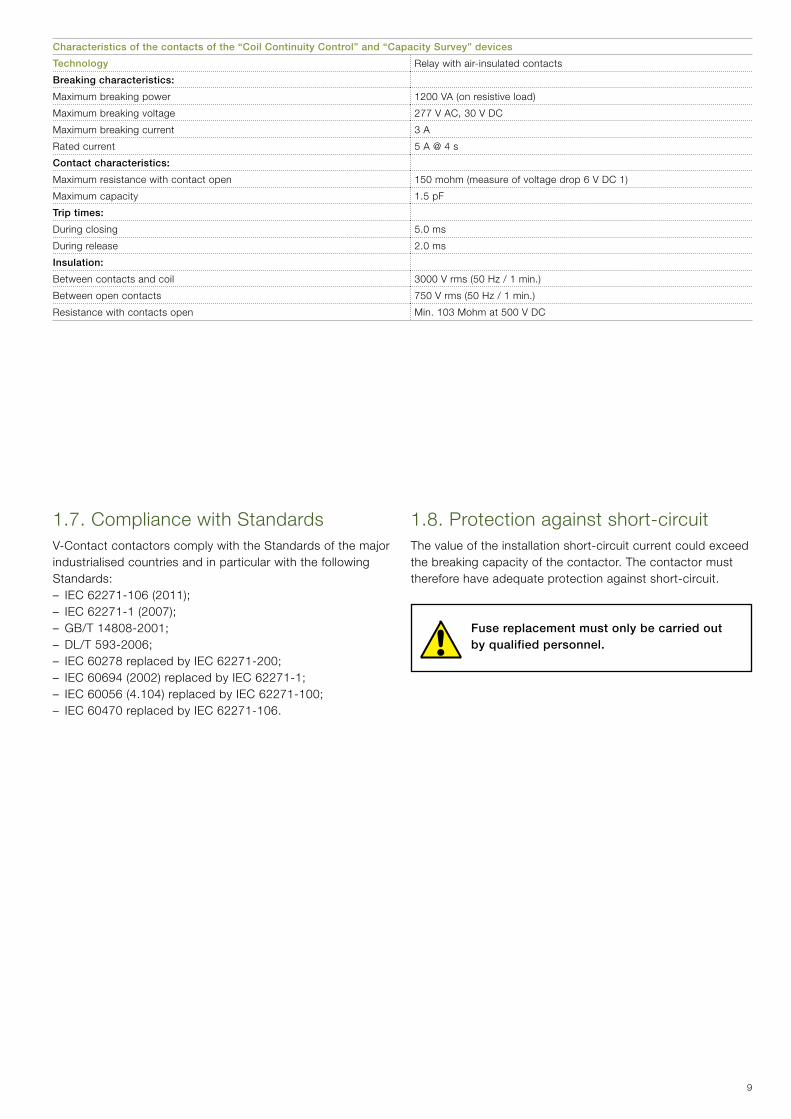
1.7. Compliance with StandardsV-Contact contactors comply with the Standards of the major industrialised countries and in particular with the following Standards:–IEC62271-106(2011);–IEC62271-1(2007);– GB/T 14808-2001;– DL/T 593-2006;– IEC 60278 replaced by IEC 62271-200;–IEC60694(2002)replacedbyIEC62271-1;–IEC60056(4.104)replacedbyIEC62271-100;– IEC 60470 replaced by IEC 62271-106.
Characteristics of the contacts of the “Coil Continuity Control” and “Capacity Survey” devices
Technology Relay with air-insulated contacts
Breaking characteristics:
Maximum breaking power 1200VA(onresistiveload)
Maximum breaking voltage 277VAC,30VDC
Maximum breaking current 3 A
Rated current 5 A @ 4 s
Contact characteristics:
Maximum resistance with contact open 150mohm(measureofvoltagedrop6VDC1)
Maximum capacity 1.5 pF
Trip times:
During closing 5.0 ms
During release 2.0 ms
Insulation:
Between contacts and coil 3000Vrms(50Hz/1min.)
Between open contacts 750Vrms(50Hz/1min.)
Resistance with contacts open Min. 103 Mohm at 500 V DC
1.8. Protection against short-circuitThe value of the installation short-circuit current could exceed the breaking capacity of the contactor. The contactor must therefore have adequate protection against short-circuit.
Fuse replacement must only be carried out by qualified personnel.
10
A
E
C
D
FB
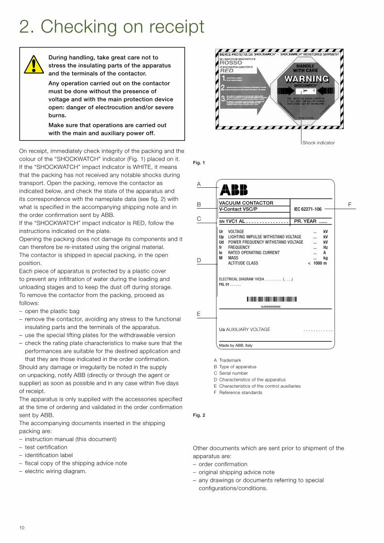
During handling, take great care not to stress the insulating parts of the apparatus and the terminals of the contactor.
Any operation carried out on the contactor must be done without the presence of voltage and with the main protection device open: danger of electrocution and/or severe burns.
Make sure that operations are carried out with the main and auxiliary power off.
Onreceipt,immediatelycheckintegrityofthepackingandthecolourofthe“SHOCKWATCH”indicator(Fig.1)placedonit.Ifthe“SHOCKWATCH”impactindicatorisWHITE,itmeansthat the packing has not received any notable shocks during transport.Openthepacking,removethecontactorasindicatedbelow,andcheckthestateoftheapparatusanditscorrespondencewiththenameplatedata(seefig.2)withwhat is specified in the accompanying shipping note and in the order confirmation sent by ABB.Ifthe“SHOCKWATCH”impactindicatorisRED,followtheinstructions indicated on the plate.Opening the packing does not damage its components and it can therefore be re-instated using the original material.Thecontactorisshippedinspecialpacking,intheopenposition.Each piece of apparatus is protected by a plastic cover to prevent any infiltration of water during the loading and unloading stages and to keep the dust off during storage.Toremovethecontactorfromthepacking,proceedasfollows:– open the plastic bag– removethecontactor,avoidinganystresstothefunctional
insulating parts and the terminals of the apparatus.– use the special lifting plates for the withdrawable version– check the rating plate characteristics to make sure that the
performances are suitable for the destined application and that they are those indicated in the order confirmation.
Should any damage or irregularity be noted in the supply onunpacking,notifyABB(directlyorthroughtheagentorsupplier) as soon as possible and in any case within five days of receipt.The apparatus is only supplied with the accessories specified at the time of ordering and validated in the order confirmation sent by ABB.The accompanying documents inserted in the shipping packing are:– instructionmanual(thisdocument)– test certification– identification label– fiscal copy of the shipping advice note– electric wiring diagram.
Shock indicator
Fig. 1
Ur VOLTAGE ... kVUp LIGHTING IMPULSE WITHSTAND VOLTAGE ... kVUd POWER FREQUENCY WITHSTAND VOLTAGE ... kVfr FREQUENCY ... HzIe RATED OPERATING CURRENT ... AM MASS ... kg ALTITUDE CLASS < 1000 m
ELECTRICAL DIAGRAM 1VCD4 . . . . . . . . . . (. . . . .)FIG. 01 . . . . . .
ALXXXXXXXXXXXXX
VACUUM CONTACTOR V-Contact VSC/P IEC 62271-106 SN 1VC1 AL . . . . . . . . . . . . . . . . PR. YEAR ......
A TrademarkB Type of apparatusC Serial numberD Characteristics of the apparatusE Characteristics of the control auxiliariesF Reference standards
Ua AUXILIARY VOLTAGE . . . . . . . . . . . .
Fig. 2
Made by ABB, Italy
2. Checking on receipt
Other documents which are sent prior to shipment of the apparatus are:– order confirmation– original shipping advice note– any drawings or documents referring to special
configurations/conditions.
11
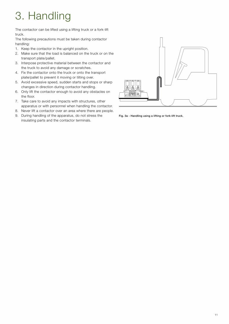
3. HandlingThe contactor can be lifted using a lifting truck or a fork-lift truck.The following precautions must be taken during contactor handling:1. Keep the contactor in the upright position.2. Make sure that the load is balanced on the truck or on the
transport plate/pallet.3. Interpose protective material between the contactor and
the truck to avoid any damage or scratches.4. Fix the contactor onto the truck or onto the transport
plate/pallet to prevent it moving or tilting over.5. Avoidexcessivespeed,suddenstartsandstopsorsharp
changes in direction during contactor handling.6. Only lift the contactor enough to avoid any obstacles on
the floor.7. Takecaretoavoidanyimpactswithstructures,other
apparatus or with personnel when handling the contactor.8. Never lift a contactor over an area where there are people.9. Duringhandlingoftheapparatus,donotstressthe
insulating parts and the contactor terminals.Fig. 3a - Handling using a lifting or fork-lift truck.
12
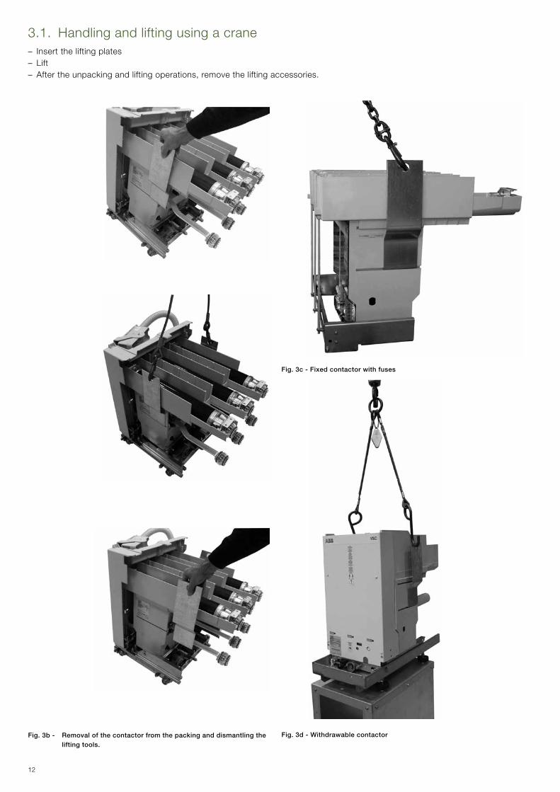
3.1. Handling and lifting using a crane – Insert the lifting plates – Lift– Aftertheunpackingandliftingoperations,removetheliftingaccessories.
Fig. 3c - Fixed contactor with fuses
Fig. 3d - Withdrawable contactorFig. 3b - Removal of the contactor from the packing and dismantling the lifting tools.

13
4. StorageWhenaperiodofstorageisforeseen,theoriginalpackingmust be put back. Store the contactor in a dry dust-free area. It must not be left outside or in adverse micro-climatic conditions:ifitisleftwithoutprotection,rustanddeteriorationof the insulation can occur.Insertspecialhygroscopicpacketsinsidethepacking,withat least one standard packet per piece of apparatus. Replace the packets approximately every 6 months.
Should the original packing no longer be available and immediateinstallationisnotpossible,storeinacovered,well-ventilated,dry,dust-free,non-corrosiveambient,withadryatmosphere,awayfromanyflammablematerialsandatatemperature between – 5 °C and + 40 °C.Inanycase,avoidanyaccidentalimpactsorpositioningwhich stresses the structure of the apparatus.
14
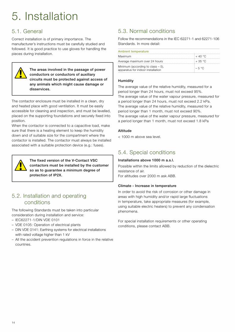
5.3. Normal conditionsFollow the recommendations in the IEC 62271-1 and 62271-106 Standards. In more detail:
Ambient temperature
Maximum + 40 °C
Average maximum over 24 hours + 35 °C
Minimum(accordingtoclass–5),apparatus for indoor installation – 5 °C
Humidity
Theaveragevalueoftherelativehumidity,measuredforaperiodlongerthan24hours,mustnotexceed95%.Theaveragevalueofthewatervapourpressure,measuredforaperiodlongerthan24hours,mustnotexceed2.2kPa.Theaveragevalueoftherelativehumidity,measuredforaperiodlongerthan1month,mustnotexceed90%.Theaveragevalueofthewatervapourpressure,measuredforaperiodlongerthan1month,mustnotexceed1.8kPa
Altitude
< 1000 m above sea level.
5.4. Special conditionsInstallations above 1000 m a.s.l.
Possible within the limits allowed by reduction of the dielectric resistance of air.For altitudes over 2000 m ask ABB.
Climate - Increase in temperature
In order to avoid the risk of corrosion or other damage in areas with high humidity and/or rapid large fluctuations intemperature,takeappropriatemeasures(forexample,using suitable electric heaters) to prevent any condensation phenomena.
For special installation requirements or other operating conditions,pleasecontactABB.
5. Installation5.1. GeneralCorrect installation is of primary importance. The manufacturer’sinstructionsmustbecarefullystudiedandfollowed. It is good practice to use gloves for handling the pieces during installation.
The areas involved in the passage of power conductors or conductors of auxiliary circuits must be protected against access of any animals which might cause damage or disservices.
Thecontactorenclosuremustbeinstalledinaclean,dryand heated place with good ventilation. It must be easily accessibleforcleaningandinspection,andmustbelevelled,placed on the supporting foundations and securely fixed into position.Whenthecontactorisconnectedtoacapacitiveload,makesure that there is a heating element to keep the humidity down and of suitable size for the compartment where the contactor is installed. The contactor must always be installed associatedwithasuitableprotectiondevice(e.g.:fuses).
The fixed version of the V-Contact VSC contactors must be installed by the customer so as to guarantee a minimum degree of protection of IP2X.
5.2. Installation and operating conditions
The following Standards must be taken into particular consideration during installation and service:– IEC62271-1/DIN VDE 0101– VDE 0105: Operation of electrical plants– DIN VDE 0141: Earthing systems for electrical installations
with rated voltage higher than 1 kV – All the accident prevention regulations in force in the relative
countries.
15
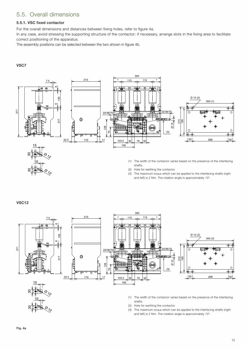
VSC7
VSC12
5.5. Overall dimensions5.5.1. VSC fixed contactor
Fortheoveralldimensionsanddistancesbetweenfixingholes,refertofigure4a.Inanycase,avoidstressingthesupportingstructureofthecontactor:ifnecessary,arrangeslotsinthefixingareatofacilitatecorrect positioning of the apparatus.The assembly positions can be selected between the two shown in figure 4b.
Fig. 4a
(1) Thewidthofthecontactorvariesbasedonthepresenceoftheinterfacingshafts.
(2) Holeforearthingthecontactor(3) Themaximumtorquewhichcanbeappliedtotheinterfacingshafts(right
and left) is 2 Nm. The rotation angle is approximately 10°.
(1) Thewidthofthecontactorvariesbasedonthepresenceoftheinterfacingshafts.
(2) Holeforearthingthecontactor(3) Themaximum torquewhichcanbeappliedtotheinterfacingshafts(right
and left) is 2 Nm. The rotation angle is approximately 10°.
16
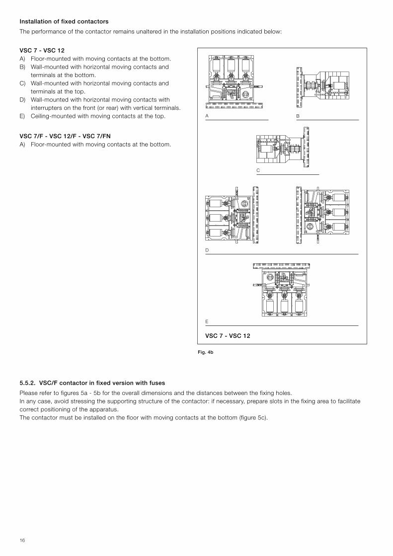
VSC 7 - VSC 12
E
BA
C
D
Fig. 4b
5.5.2. VSC/F contactor in fixed version with fuses
Please refer to figures 5a - 5b for the overall dimensions and the distances between the fixing holes.Inanycase,avoidstressingthesupportingstructureofthecontactor:ifnecessary,prepareslotsinthefixingareatofacilitatecorrect positioning of the apparatus.Thecontactormustbeinstalledonthefloorwithmovingcontactsatthebottom(figure5c).
Installation of fixed contactors
The performance of the contactor remains unaltered in the installation positions indicated below:
VSC 7 - VSC 12A) Floor-mounted with moving contacts at the bottom.B) Wall-mounted with horizontal moving contacts and
terminals at the bottom.C) Wall-mounted with horizontal moving contacts and
terminals at the top.D) Wall-mounted with horizontal moving contacts with
interruptersonthefront(orrear)withverticalterminals.E) Ceiling-mounted with moving contacts at the top.
VSC 7/F - VSC 12/F - VSC 7/FN A) Floor-mounted with moving contacts at the bottom.
17
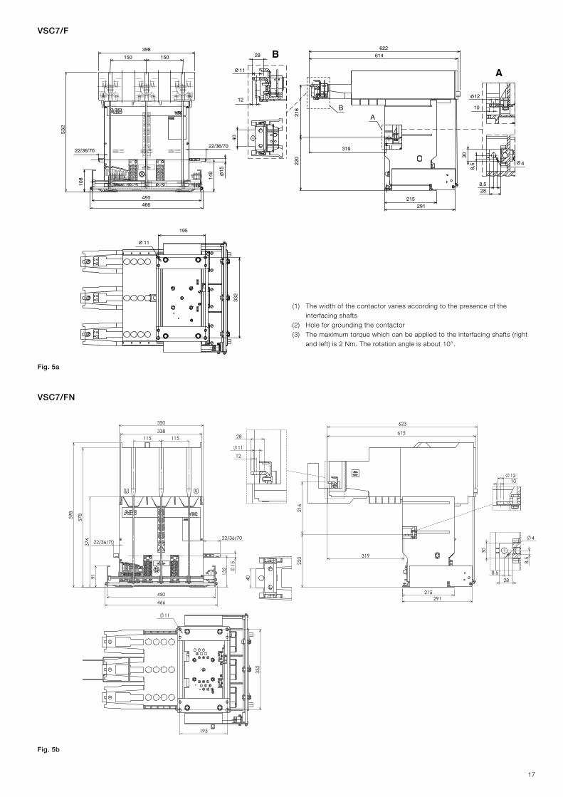
VSC7/F
11
195
332
15
115 115338
350
9137
457
8598
22/36/7022/36/70
450466
132
40 288.5
8.5
30
4
215291
220
216
319
615
623
1012
12
11
28
VSC7/FN
(1) Thewidthofthecontactorvariesaccordingtothepresenceoftheinterfacing shafts
(2) Holeforgroundingthecontactor(3) Themaximumtorquewhichcanbeappliedtotheinterfacingshafts(right
and left) is 2 Nm. The rotation angle is about 10°.
Fig. 5a
Fig. 5b

18
VSC12/F
(1) Thewidthofthecontactorvariesaccordingtothepresenceoftheinterfacing shafts
(2) Holeforgroundingthecontactor(3) Themaximumtorquewhichcanbeappliedtotheinterfacingshafts(right
and left) is 2 Nm. The rotation angle is about 10°.
Fig. 5c
Fig. 5d
Installation of the fixed contactor with VSC/F - VSC/FN fuses
19
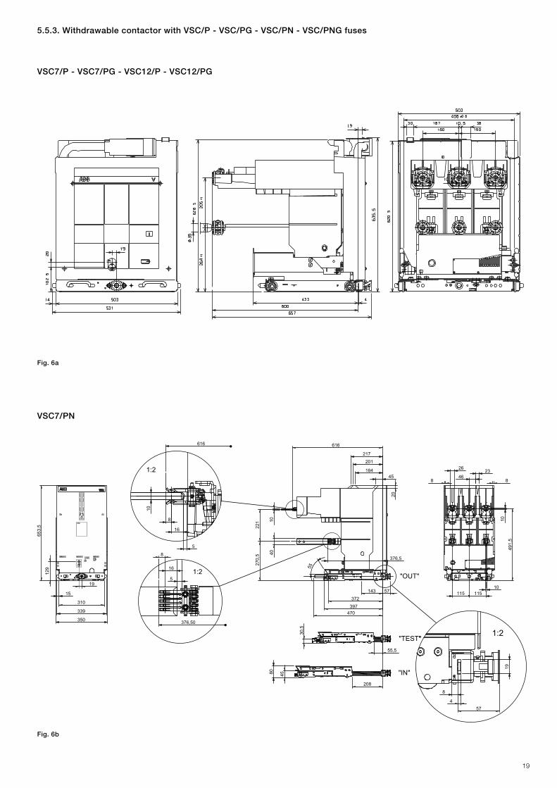
VSC7/PN
20
45184
201
397372
55
217
1040
221
270,
5
376,5
616
470
143 57
26 23
88
10115 115
491,
5
46
310
15
339
350
653,
5
19
129
8
616
16
5
10
1:2
16
8
5
376,50
1:2
19
4
8
57
55,5
30,5
"OUT"
"TEST"
"IN"208
4580
1:2
10
VSC7/P - VSC7/PG - VSC12/P - VSC12/PG
5.5.3. Withdrawable contactor with VSC/P - VSC/PG - VSC/PN - VSC/PNG fuses
Fig. 6a
Fig. 6b

20
VSC12/PN - VSC7/PNG - VSC12/PNG
20
45184201
397
372
217
4010
221
B 376,5
616
470
143 57
26
53
45
23
88
10
115 115
46
310
15
339
350
652,
5
19
A
8
616
16
5
10
16
8
5
40
376,5
1:2
19
4
8
57
55,5
30,5
"OUT"
"TEST"
"IN"
208
4580
1:2
1:2
19
530
14 503
103
4
433 4
600
657
19.5
412
205
±1
629
642
596
25.5
35
264
±1
503
150 150
9
620
30 187
458 ±0.5
42.8453 -0.5
0
340
Fig. 6c
Type Fuse A B
VSC 12/PN Single 108 269.5
VSC 7/PNG Double 129 270.5
VSC 12/PNG Double 108 269.5
Fig. 6d
VSC 12/P contactor for marine environments
21
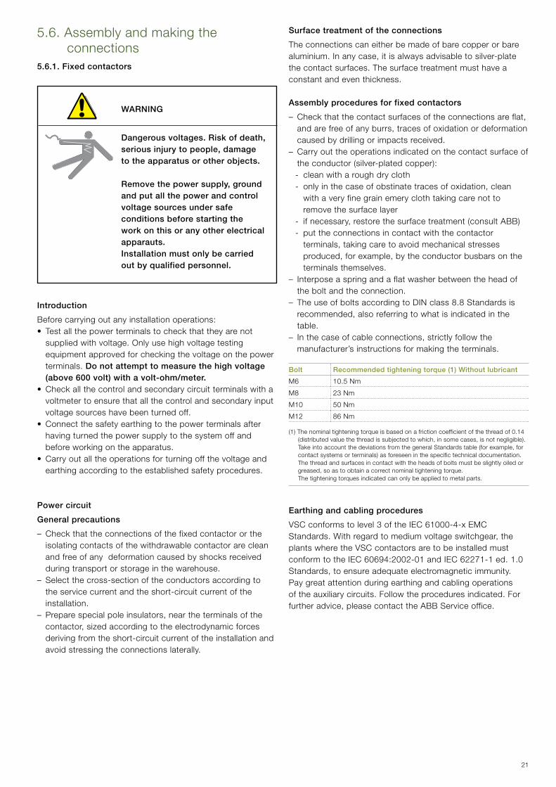
5.6. Assembly and making the connections
5.6.1. Fixed contactors
WARNING
Dangerous voltages. Risk of death, serious injury to people, damage to the apparatus or other objects.
Remove the power supply, ground and put all the power and control voltage sources under safe conditions before starting the work on this or any other electrical apparauts. Installation must only be carried out by qualified personnel.
Introduction
Before carrying out any installation operations:•Testallthepowerterminalstocheckthattheyarenot
supplied with voltage. Only use high voltage testing equipment approved for checking the voltage on the power terminals. Do not attempt to measure the high voltage (above 600 volt) with a volt-ohm/meter.
•Checkallthecontrolandsecondarycircuitterminalswithavoltmeter to ensure that all the control and secondary input voltage sources have been turned off.
•Connectthesafetyearthingtothepowerterminalsafterhaving turned the power supply to the system off and before working on the apparatus.
•Carryoutalltheoperationsforturningoffthevoltageandearthing according to the established safety procedures.
Power circuit
General precautions
– Check that the connections of the fixed contactor or the isolating contacts of the withdrawable contactor are clean and free of any deformation caused by shocks received during transport or storage in the warehouse.
– Select the cross-section of the conductors according to the service current and the short-circuit current of the installation.
– Preparespecialpoleinsulators,neartheterminalsofthecontactor,sizedaccordingtotheelectrodynamicforcesderiving from the short-circuit current of the installation and avoid stressing the connections laterally.
Surface treatment of the connections
The connections can either be made of bare copper or bare aluminium.Inanycase,itisalwaysadvisabletosilver-platethe contact surfaces. The surface treatment must have a constant and even thickness.
Assembly procedures for fixed contactors
– Checkthatthecontactsurfacesoftheconnectionsareflat,andarefreeofanyburrs,tracesofoxidationordeformationcaused by drilling or impacts received.
– Carry out the operations indicated on the contact surface of theconductor(silver-platedcopper):
- clean with a rough dry cloth -onlyinthecaseofobstinatetracesofoxidation,clean
with a very fine grain emery cloth taking care not to remove the surface layer
- ifnecessary,restorethesurfacetreatment(consultABB) - put the connections in contact with the contactor
terminals,takingcaretoavoidmechanicalstressesproduced,forexample,bytheconductorbusbarsontheterminals themselves.
– Interpose a spring and a flat washer between the head of the bolt and the connection.
– The use of bolts according to DIN class 8.8 Standards is recommended,alsoreferringtowhatisindicatedinthetable.
– Inthecaseofcableconnections,strictlyfollowthemanufacturer’sinstructionsformakingtheterminals.
Bolt Recommended tightening torque (1) Without lubricant
M6 10.5 Nm
M8 23 Nm
M10 50 Nm
M12 86 Nm
(1)Thenominaltighteningtorqueisbasedonafrictioncoefficientofthethreadof0.14(distributedvaluethethreadissubjectedtowhich,insomecases,isnotnegligible).
TakeintoaccountthedeviationsfromthegeneralStandardstable(forexample,forcontact systems or terminals) as foreseen in the specific technical documentation.
The thread and surfaces in contact with the heads of bolts must be slightly oiled or greased,soastoobtainacorrectnominaltighteningtorque.
The tightening torques indicated can only be applied to metal parts.
Earthing and cabling procedures
VSC conforms to level 3 of the IEC 61000-4-x EMC Standards.Withregardtomediumvoltageswitchgear,theplants where the VSC contactors are to be installed must conform to the IEC 60694:2002-01 and IEC 62271-1 ed. 1.0 Standards,toensureadequateelectromagneticimmunity.Pay great attention during earthing and cabling operations of the auxiliary circuits. Follow the procedures indicated. For furtheradvice,pleasecontacttheABBServiceoffice.
22
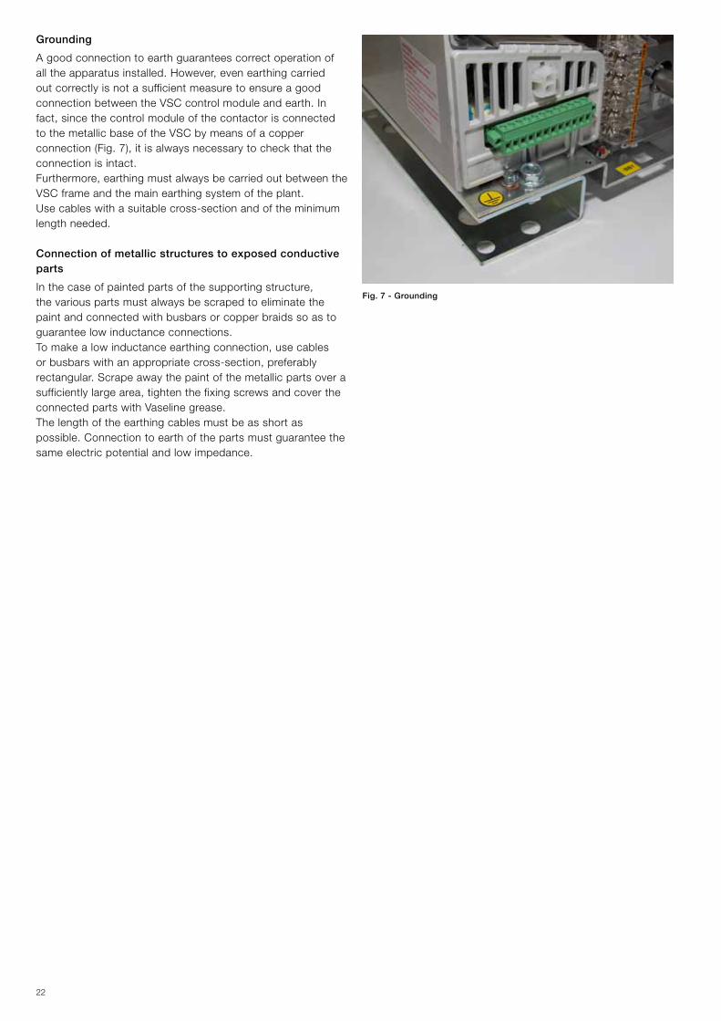
Grounding
A good connection to earth guarantees correct operation of alltheapparatusinstalled.However,evenearthingcarriedout correctly is not a sufficient measure to ensure a good connection between the VSC control module and earth. In fact,sincethecontrolmoduleofthecontactorisconnectedto the metallic base of the VSC by means of a copper connection(Fig.7),itisalwaysnecessarytocheckthattheconnection is intact.Furthermore,earthingmustalwaysbecarriedoutbetweentheVSC frame and the main earthing system of the plant.Use cables with a suitable cross-section and of the minimum length needed.
Connection of metallic structures to exposed conductive parts
Inthecaseofpaintedpartsofthesupportingstructure,the various parts must always be scraped to eliminate the paint and connected with busbars or copper braids so as to guarantee low inductance connections.Tomakealowinductanceearthingconnection,usecablesorbusbarswithanappropriatecross-section,preferablyrectangular. Scrape away the paint of the metallic parts over a sufficientlylargearea,tightenthefixingscrewsandcovertheconnected parts with Vaseline grease.The length of the earthing cables must be as short as possible. Connection to earth of the parts must guarantee the same electric potential and low impedance.
Fig. 7 - Grounding
23
Cabling
Makeshortconnections(maximum1metre)insidethemedium voltage units and avoid positioning them close to the medium voltage busbars.All long connections must follow paths as close as possible to the metallic frame. The connections must also be fitted with ferrite rings to suppress high frequency interference.It is good practice to run the cables inside metallic pipes or ducts(earthedatseveralpoints)whentheyaresubjecttoormay be a cause of interference. Cabling and earthing procedures according to IEC 61000-5-2 Standards: “Technical report: Installation and mitigation guidelines”.
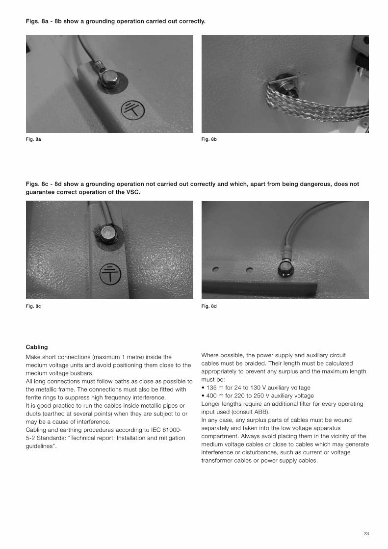
Fig. 8a Fig. 8b
Fig. 8c Fig. 8d
Figs. 8a - 8b show a grounding operation carried out correctly.
Figs. 8c - 8d show a grounding operation not carried out correctly and which, apart from being dangerous, does not guarantee correct operation of the VSC.
Wherepossible,thepowersupplyandauxiliarycircuitcables must be braided. Their length must be calculated appropriately to prevent any surplus and the maximum length must be:•135mfor24to130Vauxiliaryvoltage•400mfor220to250VauxiliaryvoltageLonger lengths require an additional filter for every operating inputused(consultABB).Inanycase,anysurpluspartsofcablesmustbewoundseparately and taken into the low voltage apparatus compartment. Always avoid placing them in the vicinity of the medium voltage cables or close to cables which may generate interferenceordisturbances,suchascurrentorvoltagetransformer cables or power supply cables.
24
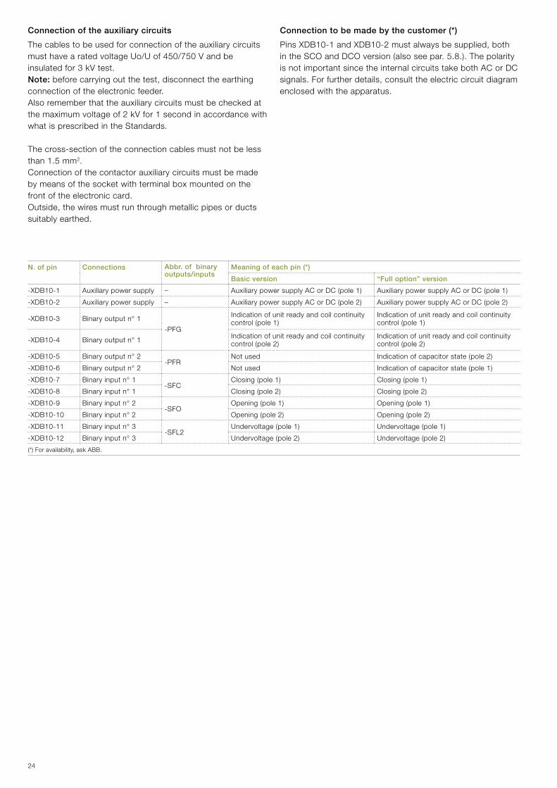
N. of pin Connections Abbr. of binary outputs/inputs
Meaning of each pin (*)
Basic version “Full option” version
-XDB10-1 Auxiliary power supply – AuxiliarypowersupplyACorDC(pole1) AuxiliarypowersupplyACorDC(pole1)
-XDB10-2 Auxiliary power supply – AuxiliarypowersupplyACorDC(pole2) AuxiliarypowersupplyACorDC(pole2)
-XDB10-3 Binary output n° 1
-PFG
Indication of unit ready and coil continuity control(pole1)
Indication of unit ready and coil continuity control(pole1)
-XDB10-4 Binary output n° 1 Indication of unit ready and coil continuity control(pole2)
Indication of unit ready and coil continuity control(pole2)
-XDB10-5 Binary output n° 2-PFR
Not used Indicationofcapacitorstate(pole2)
-XDB10-6 Binary output n° 2 Not used Indicationofcapacitorstate(pole1)
-XDB10-7 Binary input n° 1-SFC
Closing(pole1) Closing(pole1)
-XDB10-8 Binary input n° 1 Closing(pole2) Closing(pole2)
-XDB10-9 Binary input n° 2-SFO
Opening(pole1) Opening(pole1)
-XDB10-10 Binary input n° 2 Opening(pole2) Opening(pole2)
-XDB10-11 Binary input n° 3-SFL2
Undervoltage(pole1) Undervoltage(pole1)
-XDB10-12 Binary input n° 3 Undervoltage(pole2) Undervoltage(pole2)
(*)Foravailability,askABB.
Connection of the auxiliary circuits
The cables to be used for connection of the auxiliary circuits must have a rated voltage Uo/U of 450/750 V and be insulated for 3 kV test.Note: beforecarryingoutthetest,disconnecttheearthingconnection of the electronic feeder.Also remember that the auxiliary circuits must be checked at the maximum voltage of 2 kV for 1 second in accordance with what is prescribed in the Standards.
The cross-section of the connection cables must not be less than 1.5 mm2.Connection of the contactor auxiliary circuits must be made by means of the socket with terminal box mounted on the front of the electronic card.Outside,thewiresmustrunthroughmetallicpipesorductssuitably earthed.
Connection to be made by the customer (*)
PinsXDB10-1andXDB10-2mustalwaysbesupplied,bothintheSCOandDCOversion(alsoseepar.5.8.).Thepolarityis not important since the internal circuits take both AC or DC signals.Forfurtherdetails,consulttheelectriccircuitdiagramenclosed with the apparatus.
25
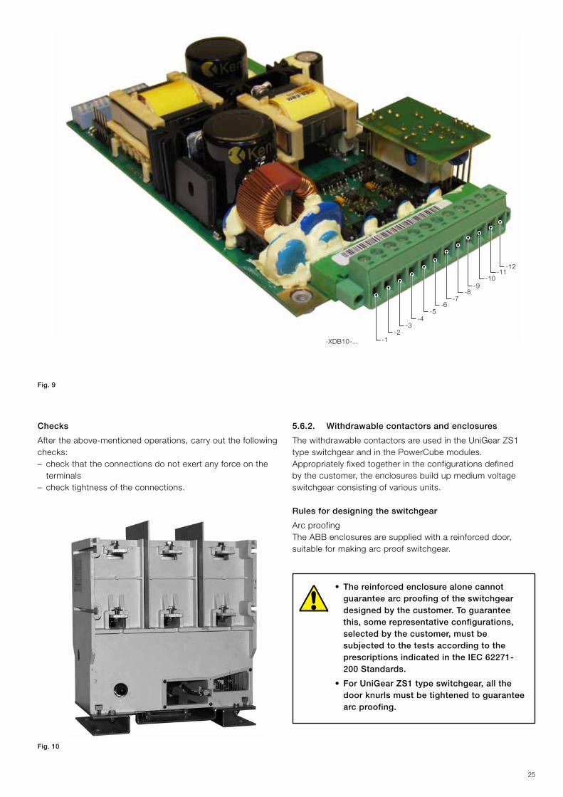
-XDB10-...
-7-8
-9
-12-11
-10
-6-5
-4-3
-2-1
Fig. 9
Checks
Aftertheabove-mentionedoperations,carryoutthefollowingchecks:– check that the connections do not exert any force on the
terminals – check tightness of the connections.
Fig. 10
5.6.2. Withdrawable contactors and enclosures
The withdrawable contactors are used in the UniGear ZS1 type switchgear and in the PowerCube modules.Appropriately fixed together in the configurations defined bythecustomer,theenclosuresbuildupmediumvoltageswitchgear consisting of various units.
Rules for designing the switchgear
Arc proofingTheABBenclosuresaresuppliedwithareinforceddoor,suitable for making arc proof switchgear.
• The reinforced enclosure alone cannot guarantee arc proofing of the switchgear designed by the customer. To guarantee this, some representative configurations, selected by the customer, must be subjected to the tests according to the prescriptions indicated in the IEC 62271-200 Standards.
• For UniGear ZS1 type switchgear, all the door knurls must be tightened to guarantee arc proofing.
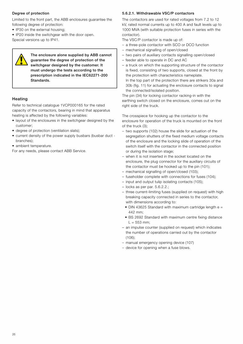
26
Degree of protection
Limitedtothefrontpart,theABBenclosuresguaranteethefollowing degree of protection:• IP30ontheexternalhousing;• IP20insidetheswitchgearwiththedooropen.Special versions up to IP41.
The enclosure alone supplied by ABB cannot guarantee the degree of protection of the switchgear designed by the customer. It must undergo the tests according to the prescription indicated in the IEC62271-200 Standards.
Heating
Refer to technical catalogue 1VCP000165 for the rated capacityofthecontactors,bearinginmindthatapparatusheating is affected by the following variables:•layoutoftheenclosuresintheswitchgeardesignedbythe
customer;•degreeofprotection(ventilationslats);•currentdensityofthepowersupplybusbars(busbarduct-
branches);•ambienttemperature.Foranyneeds,pleasecontactABBService.
5.6.2.1. Withdrawable VSC/P contactors
The contactors are used for rated voltages from 7.2 to 12 kV,ratednormalcurrentsupto400Aandfaultlevelsupto1000MVA(withsuitableprotectionfusesinserieswiththecontactor).The VSC/P contactor is made up of:– a three-pole contactor with SCO or DCO function– mechanical signalling of open/closed– two pairs of auxiliary contacts signalling open/closed– feeder able to operate in DC and AC– a truck on which the supporting structure of the contactor isfixed,consistingoftwosupports,closedatthefrontbythe protection with characteristics nameplate.
In the top part of the protection there are strikers 30a and 30b(fig.11)foractuatingtheenclosurecontactstosignalthe connected/isolated position.
Thepin(34)forlockingcontactorracking-inwiththeearthingswitchclosedontheenclosure,comesoutontheright side of the truck.
The crosspiece for hooking up the contactor to the enclosure for operation of the truck is mounted on the front ofthetruck(3);–twosupports(102)housetheslideforactuationofthe
segregation shutters of the fixed medium voltage contacts of the enclosure and the locking slide of operation of the switch itself with the contactor in the connected position or during the isolation stage;
– when it is not inserted in the socket located on the enclosure,theplugconnectorfortheauxiliarycircuitsofthecontactormustbehookeduptothepin(101);
–mechanicalsignallingofopen/closed(103);–fuseholdercompletewithconnectionsforfuses(104);– inputandoutputtulipisolatingcontacts(105);– locks as per par. 5.6.2.2.;–threecurrent-limitingfuses(suppliedonrequest)withhighbreakingcapacityconnectedinseriestothecontactor,with dimensions according to:
•DIN43625Standardwithmaximumcartridgelengthe=442 mm;
•BS2692StandardwithmaximumcentrefixingdistanceL = 553 mm;
– animpulsecounter(suppliedonrequest)whichindicatesthe number of operations carried out by the contactor (106);
– manualemergencyopeningdevice(107)– device for opening when a fuse blows.
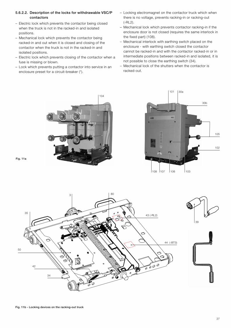
27
35
80
50
34
43(-RL2)
44(-BT3)
39
42
101 30a
30b
105
102
108 107 106 103
3
104
5.6.2.2. Description of the locks for withdrawable VSC/P contactors
– Electric lock which prevents the contactor being closed when the truck is not in the racked-in and isolated positions.
– Mechanical lock which prevents the contactor being racked-in and out when it is closed and closing of the contactor when the truck is not in the racked-in and isolated positions.
– Electric lock which prevents closing of the contactor when a fuse is missing or blown.
– Lock which prevents putting a contactor into service in an enclosurepresetforacircuit-breaker(*).
Fig. 11a
Fig. 11b - Locking devices on the racking-out truck
– Locking electromagnet on the contactor truck which when thereisnovoltage,preventsracking-inorracking-out(-RL2).
– Mechanical lock which prevents contactor racking-in if the enclosuredoorisnotclosed(requiresthesameinterlockinthefixedpart)(108).
– Mechanical interlock with earthing switch placed on the enclosure - with earthing switch closed the contactor cannot be racked-in and with the contactor racked-in or in intermediatepositionsbetweenracked-inandisolated,itisnotpossibletoclosetheearthingswitch(34).
– Mechanical lock of the shutters when the contactor is racked-out.
28
– Key lock on contactor racking-in - it is only possible to activate the lock and free the key preventing contactor racking-in with the contactor in the isolated position.
– Key lock with earthing switch open - this can only be activated with the earthing switch open. The key can only be removed with the electric lock activated.
– Key lock with earthing switch closed - this can only be activated with the contactor in the isolated position and with the earthing switch closed. The key can only be removed with the lock activated.
– Preset for independent padlocks on the shutters and in the closed and/or open position.
– Electric lock on racking-in and racking-out with the door open(microswitchonthedoor)oftheenclosureconnectedin series with the locking electromagnet on the contactor truck.
– Key lock on earthing truck racking-in - with the lock activatedalltheoperationswiththecontactorarepossible,but positioning the earthing truck in the isolated position starting from the racked-out position is not allowed.
– Mechanical lock which prevents racking-out of the connector of the auxiliaries when the contactor is racked-in and during racking-in and racking-out.
– Electro-mechanical lock on de-energisation for the earthing switch,whichwhenthereisnovoltagepreventstheearthing switch operations.
– Electro-mechanical lock on the compartment door.
5.6.2.3. VSC/PN and VSC/PNG withdrawable contactors
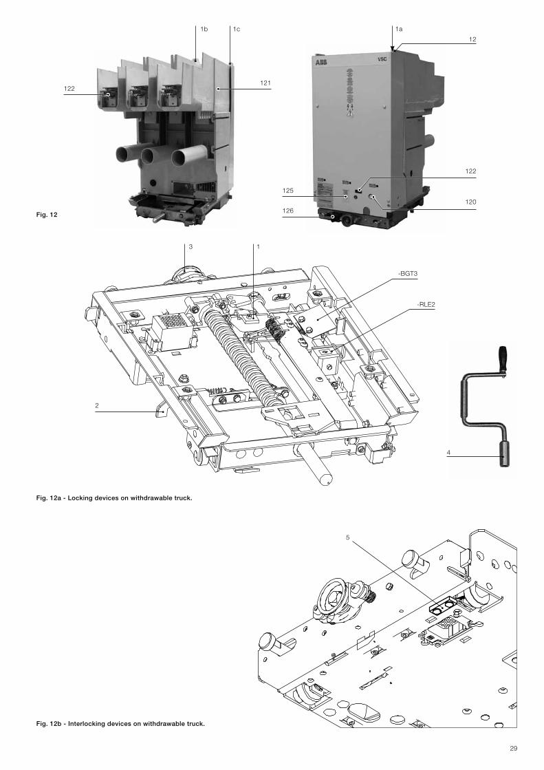
The VSC/PN contactors are used for rated voltages from 7.2 to12kV,ratedthermalcurrentsupto400Aandfaultlevelsupto1000MVA(withsuitableprotectionfusesinserieswiththecontactor).Inthesameway,theVSC/PNGcontactoris used for 7.2 kV rated voltage and 400 A rated thermal current. Both the VSC/PN and the VSC/PNG versions of contactors consist of:– a three-pole contactor with SCO or DCO operation–afuseholdercompletewithterminalsforfuses(121).Intheupperparttherearestrikers1a,1band1c(fig.12-page29) for activating the enclosure contacts for signalling the connected/test/isolated position
–amechanicalopen/closedsignallingdevice(120)– two pairs of auxiliary contacts signalling open/closed – feeder able to operate in d.c. and a.c.– a truck on which the base plate of the contactor is fixed
and the front protective screen by means of two supports. Attherear,twopinsarepositionedonthesidewallsof
the truck for locking contactor racking-in with the earthing switchopenontheenclosure,whereasthe45°slidesoperate the segregation shutters of the medium voltage fixed contacts of the enclosure. The crosspiece for hooking the contactor onto the enclosure for truck operation is mounted on the front of the truck
– thejaw-typeinputandoutputisolatingcontacts(122)– the locks as per par. 5.6.2.4.– threecurrent-limitingfuses(suppliedonrequest)withhigh
breakingcapacityconnectedinserieswiththecontactor,with dimensions according to:
•DIN43625Standardwithmaximumcartridgelengthe=442mm(singlecartridge)
•BS2692StandardwithmaximumfixingdistanceL=553mm(singleand/ordoublecartridge)
– a mechanical operation counter which indicates the number ofoperationscarriedoutbythecontactor(122)
– a manual emergency opening device even when energised withmediumvoltage(125)
–adeviceforopeningwhenafuseblows,withrelativefuseblown indication.
5.6.2.4. Description of the locks for VSC/PN and VSC/PNG withdrawable contactors
– Electric lock which prevents the contactor being closed whenthetruckisnotinthe“racked-in”(200mm),“test”(47.5mm)and“racked-out”(0mm)positions(-BGT3)(fig.12a).
– Mechanical lock which prevents the contactor being racked-inandoutwhenitisclosed,andcontactorclosingwhenthetruckisnotinthe“racked-in”,“test”and“racked-out”positions(1)(fig.12a).
– Electric lock which prevents contactor closing when a fuse is missing or blown.
–Lockingelectromagnetonthecontactortruckwhich,whenthereisnovoltage,preventsracking-inorracking-out(-RL2)(fig.12a).
– Mechanical lock which prevents contactor racking-in if the enclosuredoorisnotclosed(requiresareciprocalinterlockinthefixedpart)(126).
–Mechanicallockforthe“test”position(2)(fig.12a).–Lockfordifferentcurrents(5)(fig.12a).
(*) Thislockconsistsofsomepinsassembledintheplugsoftheauxiliarycircuitswhich,withasuitablecode,preventconnectionoftheplugintheenclosuresocket.The lock also foresees compulsory application of the locking magnet in the truck.
29
-RLE2
-BGT3
13
2
4
5
12
1b
121122
122
120
1c
126
125
1a
Fig. 12
Fig. 12a - Locking devices on withdrawable truck.
Fig. 12b - Interlocking devices on withdrawable truck.
30
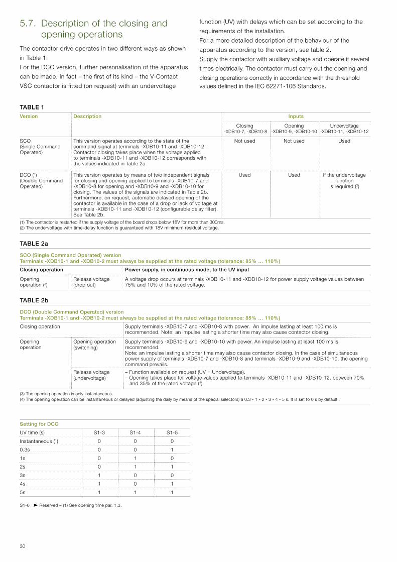
5.7. Description of the closing and opening operations
The contactor drive operates in two different ways as shown
in Table 1.
FortheDCOversion,furtherpersonalisationoftheapparatus
can be made. In fact – the first of its kind – the V-Contact
VSCcontactorisfitted(onrequest)withanundervoltage
function(UV)withdelayswhichcanbesetaccordingtothe
requirements of the installation.
For a more detailed description of the behaviour of the
apparatusaccordingtotheversion,seetable2.
Supply the contactor with auxiliary voltage and operate it several
times electrically. The contactor must carry out the opening and
closing operations correctly in accordance with the threshold values defined in the IEC 62271-106 Standards.
TABLE 1Version Description Inputs
Closing -XDB10-7,-XDB10-8
Opening-XDB10-9,-XDB10-10
Undervoltage -XDB10-11,-XDB10-12
SCO (SingleCommandOperated)
This version operates according to the state of the command signal at terminals -XDB10-11 and -XDB10-12. Contactor closing takes place when the voltage applied to terminals -XDB10-11 and -XDB10-12 corresponds with the values indicated in Table 2a
Not used Not used Used
DCO(1) (DoubleCommandOperated)
This version operates by means of two independent signals for closing and opening applied to terminals -XDB10-7 and -XDB10-8 for opening and -XDB10-9 and -XDB10-10 for closing. The values of the signals are indicated in Table 2b. Furthermore,onrequest,automaticdelayedopeningofthecontactor is available in the case of a drop or lack of voltage at terminals-XDB10-11and-XDB10-12(configurabledelayfilter).See Table 2b.
Used Used If the undervoltage function
isrequired(2)
(1)The contactor is restarted if the supply voltage of the board drops below 18V for more than 300ms. (2)The undervoltage with time-delay function is guaranteed with 18V minimum residual voltage.
TABLE 2a
SCO (Single Command Operated) versionTerminals -XDB10-1 and -XDB10-2 must always be supplied at the rated voltage (tolerance: 85% … 110%)
Closing operation Power supply, in continuous mode, to the UV input
Opening operation(3)
Release voltage (dropout)
A voltage drop occurs at terminals -XDB10-11 and -XDB10-12 for power supply voltage values between 75%and10%oftheratedvoltage.
TABLE 2b
DCO (Double Command Operated) versionTerminals -XDB10-1 and -XDB10-2 must always be supplied at the rated voltage (tolerance: 85% … 110%)
Closing operation Supply terminals -XDB10-7 and -XDB10-8 with power. An impulse lasting at least 100 ms is recommended. Note: an impulse lasting a shorter time may also cause contactor closing.
Opening operation
Opening operation(switching)
Supply terminals -XDB10-9 and -XDB10-10 with power. An impulse lasting at least 100 ms is recommended. Note: an impulse lasting a shorter time may also cause contactor closing. In the case of simultaneous powersupplyofterminals-XDB10-7and-XDB10-8andterminals-XDB10-9and-XDB10-10,theopeningcommand prevails.
Release voltage (undervoltage)
–Functionavailableonrequest(UV=Undervoltage).–Openingtakesplaceforvoltagevaluesappliedtoterminals-XDB10-11and-XDB10-12,between70%and35%oftheratedvoltage(4)
(3)Theopeningoperationisonlyinstantaneous.(4)Theopeningoperationcanbeinstantaneousordelayed(adjustingthedailybymeansofthespecialselectors)a0.3-1-2-3-4-5s.Itissetto0sbydefault.
Setting for DCO
UVtime(s) S1-3 S1-4 S1-5
Instantaneous (1) 0 0 0
0.3s 0 0 1
1s 0 1 0
2s 0 1 1
3s 1 0 0
4s 1 0 1
5s 1 1 1
S1-6 Reserved–(1)Seeopeningtimepar.1.3.
31
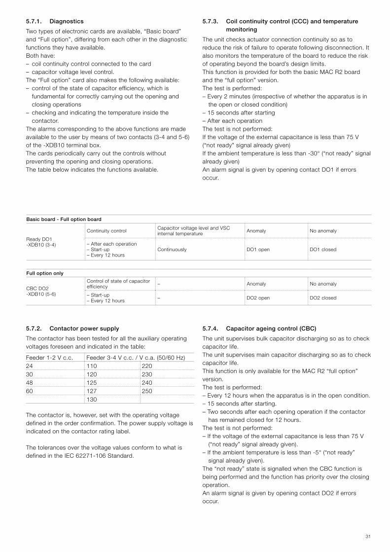
5.7.2. Contactor power supply
The contactor has been tested for all the auxiliary operating voltages foreseen and indicated in the table:
Feeder 1-2 V c.c. Feeder3-4Vc.c./Vc.a.(50/60Hz)24 110 22030 120 23048 125 24060 127 250
130
Thecontactoris,however,setwiththeoperatingvoltagedefined in the order confirmation. The power supply voltage is indicated on the contactor rating label.
The tolerances over the voltage values conform to what is defined in the IEC 62271-106 Standard.
Basic board - Full option board
Ready DO1-XDB10(3-4)
Continuity control Capacitor voltage level and VSC internal temperature Anomaly No anomaly
– After each operation– Start-up– Every 12 hours
Continuously DO1 open DO1 closed
Full option only
CBC DO2-XDB10(5-6)
Control of state of capacitor efficiency – Anomaly No anomaly
– Start-up– Every 12 hours – DO2 open DO2 closed
5.7.1. Diagnostics
Twotypesofelectroniccardsareavailable,“Basicboard”and“Fulloption”,differingfromeachotherinthediagnosticfunctions they have available.Both have:– coil continuity control connected to the card – capacitor voltage level control.The “Full option” card also makes the following available:–controlofthestateofcapacitorefficiency,whichis
fundamental for correctly carrying out the opening and closing operations
– checking and indicating the temperature inside the contactor.
The alarms corresponding to the above functions are made availabletotheuserbymeansoftwocontacts(3-4and5-6)of the -XDB10 terminal box.The cards periodically carry out the controls without preventing the opening and closing operations.The table below indicates the functions available.
5.7.3. Coil continuity control (CCC) and temperature monitoring
The unit checks actuator connection continuity so as to reduce the risk of failure to operate following disconnection. It also monitors the temperature of the board to reduce the risk ofoperatingbeyondtheboard’sdesignlimits.This function is provided for both the basic MAC R2 board and the “full option” version.The test is performed:–Every2minutes(irrespectiveofwhethertheapparatusisin
the open or closed condition)– 15 seconds after starting– After each operationThe test is not performed:If the voltage of the external capacitance is less than 75 V (“notready”signalalreadygiven)Iftheambienttemperatureislessthan-30°(“notready”signalalready given)An alarm signal is given by opening contact DO1 if errors occur.
5.7.4. Capacitor ageing control (CBC)
The unit supervises bulk capacitor discharging so as to check capacitor life.The unit supervises main capacitor discharging so as to check capacitor life.This function is only available for the MAC R2 “full option” version.The test is performed:– Every 12 hours when the apparatus is in the open condition.– 15 seconds after starting.– Two seconds after each opening operation if the contactor
has remained closed for 12 hours.The test is not performed:– If the voltage of the external capacitance is less than 75 V (“notready”signalalreadygiven).
–Iftheambienttemperatureislessthan-5°(“notready”signal already given).
The “not ready” state is signalled when the CBC function is being performed and the function has priority over the closing operation.An alarm signal is given by opening contact DO2 if errors occur.
32
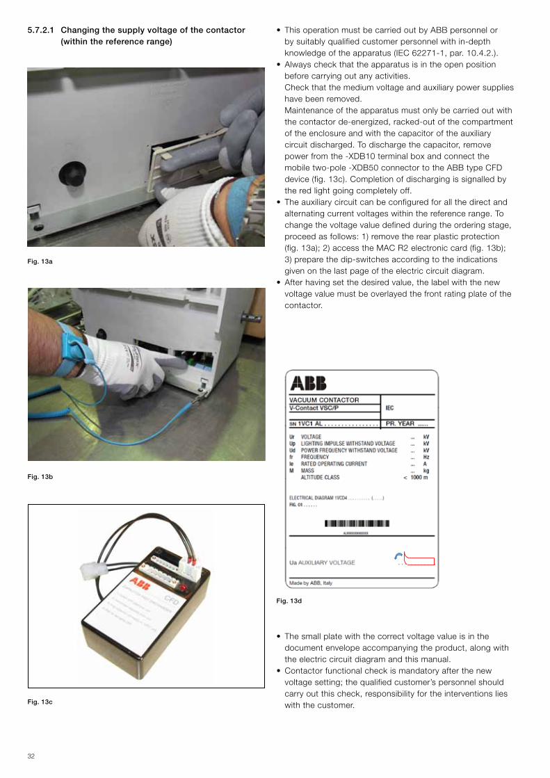
• ThisoperationmustbecarriedoutbyABBpersonnelorby suitably qualified customer personnel with in-depth knowledgeoftheapparatus(IEC62271-1,par.10.4.2.).
• Alwayscheckthattheapparatusisintheopenpositionbefore carrying out any activities.
Check that the medium voltage and auxiliary power supplies have been removed.
Maintenance of the apparatus must only be carried out with thecontactorde-energized,racked-outofthecompartmentof the enclosure and with the capacitor of the auxiliary circuitdischarged.Todischargethecapacitor,removepower from the -XDB10 terminal box and connect the mobile two-pole -XDB50 connector to the ABB type CFD device(fig.13c).Completionofdischargingissignalledbythe red light going completely off.
• Theauxiliarycircuitcanbeconfiguredforallthedirectandalternating current voltages within the reference range. To changethevoltagevaluedefinedduringtheorderingstage,proceed as follows: 1) remove the rear plastic protection (fig.13a);2)accesstheMACR2electroniccard(fig.13b);3) prepare the dip-switches according to the indications given on the last page of the electric circuit diagram.
• Afterhavingsetthedesiredvalue,thelabelwiththenewvoltage value must be overlayed the front rating plate of the contactor.
Fig. 13a
Fig. 13b
Fig. 13c
Fig. 13d
• Thesmallplatewiththecorrectvoltagevalueisinthedocumentenvelopeaccompanyingtheproduct,alongwiththe electric circuit diagram and this manual.
• Contactorfunctionalcheckismandatoryafterthenewvoltagesetting;thequalifiedcustomer’spersonnelshouldcarryoutthischeck,responsibilityfortheinterventionslieswith the customer.
5.7.2.1 Changing the supply voltage of the contactor (within the reference range)
33
A B
1
1
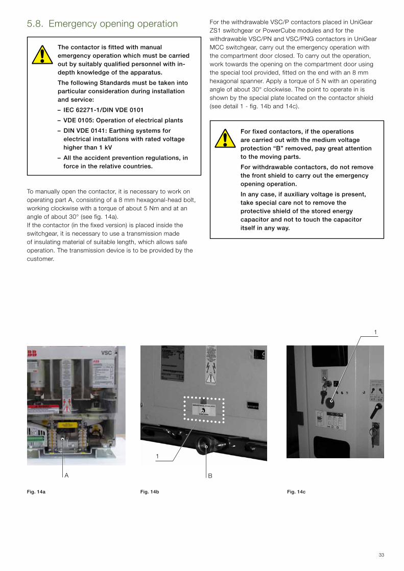
For the withdrawable VSC/P contactors placed in UniGear ZS1 switchgear or PowerCube modules and for the withdrawable VSC/PN and VSC/PNG contactors in UniGear MCCswitchgear,carryouttheemergencyoperationwiththecompartmentdoorclosed.Tocarryouttheoperation,work towards the opening on the compartment door using thespecialtoolprovided,fittedontheendwithan8mmhexagonal spanner. Apply a torque of 5 N with an operating angle of about 30° clockwise. The point to operate in is shown by the special plate located on the contactor shield (seedetail1-fig.14band14c).
For fixed contactors, if the operations are carried out with the medium voltage protection “B” removed, pay great attention to the moving parts.
For withdrawable contactors, do not remove the front shield to carry out the emergency opening operation.
In any case, if auxiliary voltage is present, take special care not to remove the protective shield of the stored energy capacitor and not to touch the capacitor itself in any way.
5.8. Emergency opening operation
The contactor is fitted with manual emergency operation which must be carried out by suitably qualified personnel with in-depth knowledge of the apparatus.
The following Standards must be taken into particular consideration during installation and service:
– IEC 62271-1/DIN VDE 0101
– VDE 0105: Operation of electrical plants
– DIN VDE 0141: Earthing systems for electrical installations with rated voltage higher than 1 kV
– All the accident prevention regulations, in force in the relative countries.
Tomanuallyopenthecontactor,itisnecessarytoworkonoperatingpartA,consistingofa8mmhexagonal-headbolt,working clockwise with a torque of about 5 Nm and at anangleofabout30°(seefig.14a).Ifthecontactor(inthefixedversion)isplacedinsidetheswitchgear,itisnecessarytouseatransmissionmadeofinsulatingmaterialofsuitablelength,whichallowssafeoperation. The transmission device is to be provided by thecustomer.
Fig. 14a Fig. 14b Fig. 14c
34
0,5mm
6.1. General procedures
All the operations regarding putting into service must be carried out by ABB personnel or by suitably qualified customer personnel with in-depth knowledge of the apparatus and of the installation.
Beforeputtingtheapparatusintoservice,carryoutthefollowing operations as well as those indicated in the table:– check that the voltage and current applied are within the
specified rated values– check tightness of the power connections of the fixed
contactors and integrity of the isolating contacts of the withdrawable contactors
– carefully clean the sheets and insulating parts with brushes and clean dry cloths. Avoid using jets of compressed air
– check the earthing connection of the fixed contactors–checkthatnoforeignbodies,suchasbitsofpacking,have
got into the moving parts
– check that the value of the power supply voltage of the circuits isbetween85%and110%oftheratedauxiliaryvoltageoftheapparatus
– check that the contactor vacuum interrupter has not been damagedduetoaccidentalimpacts.Incaseofdoubt,carryout the check indicated in paragraph 7.3. Table 4.
– make sure that all the barriers and protective shields are correctly installed
– carry out the inspections indicated in table 3.
Oncompletionoftheoperationsindicated,checkthateverything is put back in its original position.
The check can only be considered as passed if all the tests indicated have had a positive outcome.In the case of a negative check, do not put the apparatus into service and, if necessary, contact ABB Service.
TAB. 3
Item inspected Procedure Positive check
1 Insulation resistance MediumvoltagecircuitWitha2500Vmegger,measuretheinsulation resistance between the phases and the exposed conductive part of the circuit.
The insulation resistance should be at least 50 Mohm.
2 Drive.Open/closedindicator,operationcounter(ifprovided)
Carry out a few closing and opening operations of the contactor.
Operations and signals normal.
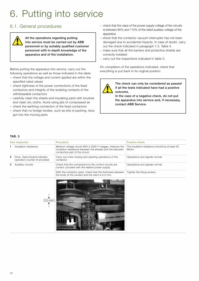
3 Auxiliary circuits Check that the connections to the control circuits are correct: proceed with the relative power supply.
Operations and signals normal.
Withthecontactoropen,checkthatthethicknessbetweenthe body of the contact and the stem is 0.5 mm.
Tighten the fixing screws.
6. Putting into service
35
6.2. Racking the VSC/P contactor in and out
• Should operations be carried out with the contactor racked-out of the switchgear, pay great attention to the moving parts.
• The contactor must only be racked into the unit in the open position. Racking-in and racking-out must be gradual to avoid shocks which might deform the mechanical interlocks.
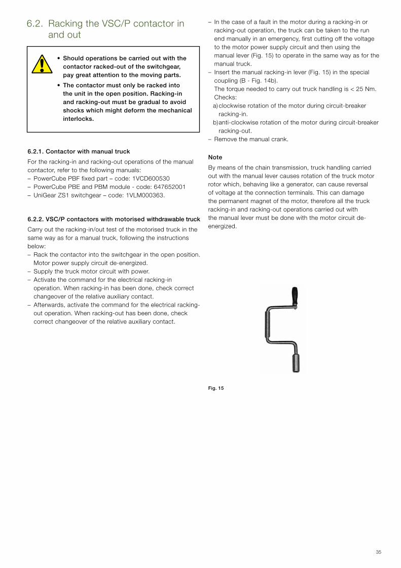
Fig. 15
– In the case of a fault in the motor during a racking-in or racking-outoperation,thetruckcanbetakentotherunendmanuallyinanemergency,firstcuttingoffthevoltageto the motor power supply circuit and then using the manuallever(Fig.15)tooperateinthesamewayasforthemanual truck.
–Insertthemanualracking-inlever(Fig.15)inthespecialcoupling(B-Fig.14b).
The torque needed to carry out truck handling is < 25 Nm. Checks: a) clockwise rotation of the motor during circuit-breaker
racking-in. b) anti-clockwise rotation of the motor during circuit-breaker
racking-out.– Remove the manual crank.
Note
Bymeansofthechaintransmission,truckhandlingcarriedout with the manual lever causes rotation of the truck motor rotorwhich,behavinglikeagenerator,cancausereversalof voltage at the connection terminals. This can damage thepermanentmagnetofthemotor,thereforeallthetruckracking-in and racking-out operations carried out with the manual lever must be done with the motor circuit de-energized.
6.2.1. Contactor with manual truck
For the racking-in and racking-out operations of the manual contactor,refertothefollowingmanuals:– PowerCube PBF fixed part – code: 1VCD600530– PowerCube PBE and PBM module - code: 647652001– UniGear ZS1 switchgear – code: 1VLM000363.
6.2.2. VSC/P contactors with motorised withdrawable truck
Carry out the racking-in/out test of the motorised truck in thesamewayasforamanualtruck,followingtheinstructionsbelow:– Rack the contactor into the switchgear in the open position. Motor power supply circuit de-energized.– Supply the truck motor circuit with power.– Activate the command for the electrical racking-in operation.Whenracking-inhasbeendone,checkcorrectchangeover of the relative auxiliary contact.
–Afterwards,activatethecommandfortheelectricalracking-outoperation.Whenracking-outhasbeendone,checkcorrect changeover of the relative auxiliary contact.
36
7. MaintenanceMaintenance operations are aimed at ensuring trouble-free operation of the apparatus for the longest possible time. The following operations must be carried out in accordance with the IEC 61208/DIN 31051 Standards: Inspection: Assessment of the actual conditions Servicing: Measures to be taken to maintain the specified conditions Repairs: Measures to be taken to restore the specified conditions.
Notes
The following rules must be respected for all maintenance operations:– the relative specifications indicated in the “Standards and
specifications” chapter;– the regulations for safety in the workplace indicated in the
“Putting into service and running” chapter;– the regulations and specifications in the country of
installation.
7.1. General It is good practice to keep a maintenance card and a service book where all the operations carried out can be noted down indetail,togetherwiththedate,descriptionoftheanomalyandthereferencesofdataneededtoidentifytheapparatus,etc.(seechapter2).Experience gained in use of the apparatus will allow the optimal time intervals for interventions to be established. In anycase,inspectionoftheapparatusnotmorethanoneyearafter it has been put into service is recommended.Incaseofneedandforfurtherdetails,pleaserefertowhatisprescribedinarticle10.4.2oftheStandard(IEC62271-1).Inanycase,foranyproblems,pleasedonothesitatetocontact us.
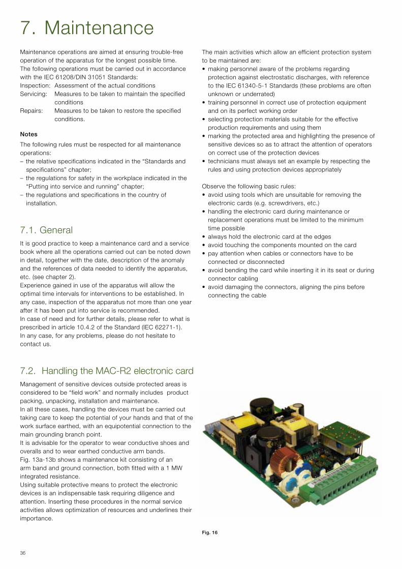
7.2. Handling the MAC-R2 electronic cardManagement of sensitive devices outside protected areas is considered to be “field work” and normally includes product packing,unpacking,installationandmaintenance.Inallthesecases,handlingthedevicesmustbecarriedouttaking care to keep the potential of your hands and that of the worksurfaceearthed,withanequipotentialconnectiontothemain grounding branch point.It is advisable for the operator to wear conductive shoes and overalls and to wear earthed conductive arm bands. Fig. 13a-13b shows a maintenance kit consisting of an armbandandgroundconnection,bothfittedwitha1MWintegrated resistance.Using suitable protective means to protect the electronic devices is an indispensable task requiring diligence and attention. Inserting these procedures in the normal service activities allows optimization of resources and underlines their importance.
The main activities which allow an efficient protection system to be maintained are:• makingpersonnelawareoftheproblemsregardingprotectionagainstelectrostaticdischarges,withreferencetotheIEC61340-5-1Standards(theseproblemsareoftenunknown or underrated)
• trainingpersonnelincorrectuseofprotectionequipmentand on its perfect working order
• selectingprotectionmaterialssuitablefortheeffectiveproduction requirements and using them
• markingtheprotectedareaandhighlightingthepresenceofsensitive devices so as to attract the attention of operators on correct use of the protection devices
• techniciansmustalwayssetanexamplebyrespectingtherules and using protection devices appropriately
Observe the following basic rules:• avoidusingtoolswhichareunsuitableforremovingthe
electroniccards(e.g.screwdrivers,etc.)• handlingtheelectroniccardduringmaintenanceor
replacement operations must be limited to the minimum time possible
• alwaysholdtheelectroniccardattheedges• avoidtouchingthecomponentsmountedonthecard• payattentionwhencablesorconnectorshavetobe
connected or disconnected• avoidbendingthecardwhileinsertingitinitsseatorduring
connector cabling • avoiddamagingtheconnectors,aligningthepinsbefore
connecting the cable
Fig. 16
37
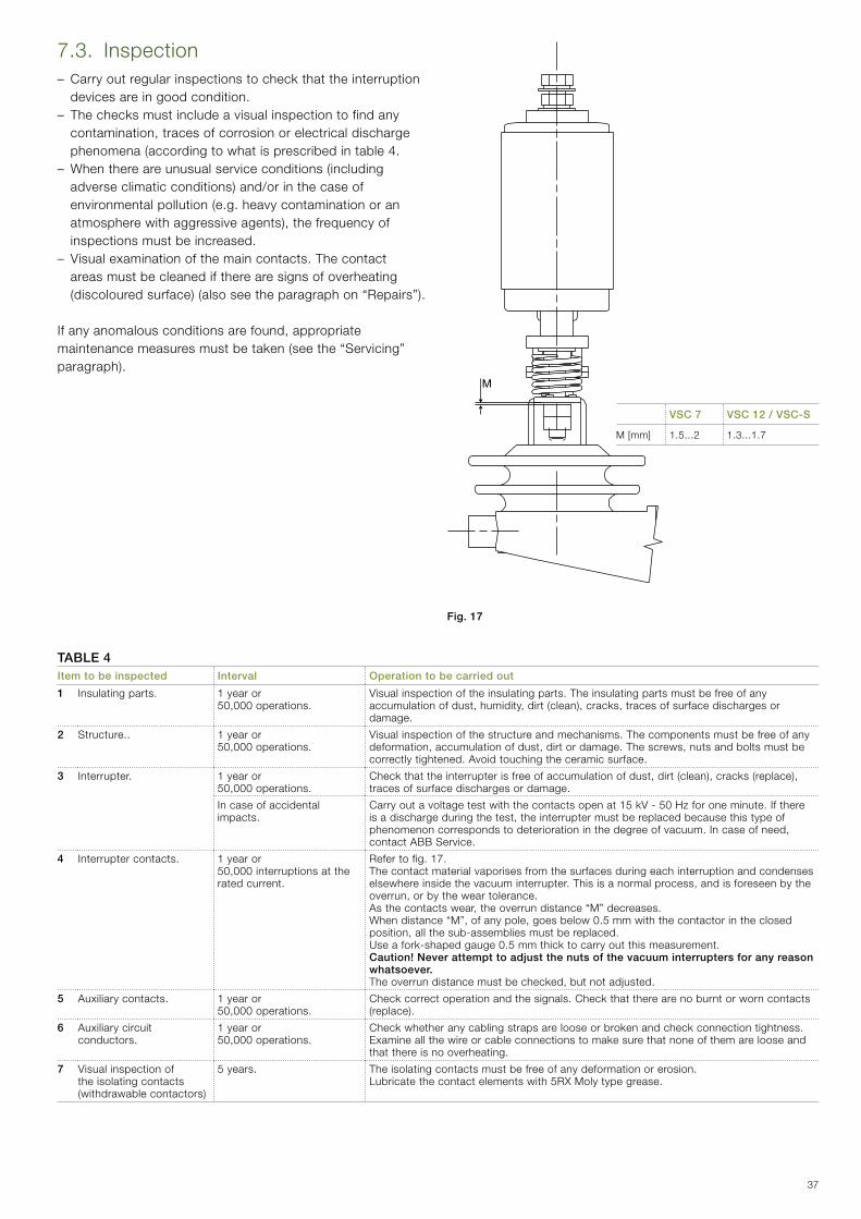
7.3. Inspection– Carry out regular inspections to check that the interruption
devices are in good condition.– The checks must include a visual inspection to find any contamination,tracesofcorrosionorelectricaldischargephenomena(accordingtowhatisprescribedintable4.
–Whenthereareunusualserviceconditions(includingadverse climatic conditions) and/or in the case of environmentalpollution(e.g.heavycontaminationoranatmospherewithaggressiveagents),thefrequencyofinspections must be increased.
– Visual examination of the main contacts. The contact areas must be cleaned if there are signs of overheating (discolouredsurface)(alsoseetheparagraphon“Repairs”).
Ifanyanomalousconditionsarefound,appropriatemaintenancemeasuresmustbetaken(seethe“Servicing”paragraph).
Fig. 17
VSC 7 VSC 12 / VSC-S
M [mm] 1.5...2 1.3...1.7
TABLE 4Item to be inspected Interval Operation to be carried out
1 Insulating parts. 1 year or 50,000operations.
Visual inspection of the insulating parts. The insulating parts must be free of any accumulationofdust,humidity,dirt(clean),cracks,tracesofsurfacedischargesordamage.
2 Structure.. 1 year or 50,000operations.
Visual inspection of the structure and mechanisms. The components must be free of any deformation,accumulationofdust,dirtordamage.Thescrews,nutsandboltsmustbecorrectly tightened. Avoid touching the ceramic surface.
3 Interrupter. 1 year or 50,000operations.
Checkthattheinterrupterisfreeofaccumulationofdust,dirt(clean),cracks(replace),traces of surface discharges or damage.
In case of accidental impacts.
Carry out a voltage test with the contacts open at 15 kV - 50 Hz for one minute. If there isadischargeduringthetest,theinterruptermustbereplacedbecausethistypeofphenomenoncorrespondstodeteriorationinthedegreeofvacuum.Incaseofneed,contact ABB Service.
4 Interrupter contacts. 1 year or 50,000interruptionsattherated current.
Refer to fig. 17. The contact material vaporises from the surfaces during each interruption and condenses elsewhereinsidethevacuuminterrupter.Thisisanormalprocess,andisforeseenbytheoverrun,orbytheweartolerance.Asthecontactswear,theoverrundistance“M”decreases.Whendistance“M”,ofanypole,goesbelow0.5mmwiththecontactorintheclosedposition,allthesub-assembliesmustbereplaced.Use a fork-shaped gauge 0.5 mm thick to carry out this measurement.Caution! Never attempt to adjust the nuts of the vacuum interrupters for any reason whatsoever.Theoverrundistancemustbechecked,butnotadjusted.
5 Auxiliary contacts. 1 year or 50,000operations.
Check correct operation and the signals. Check that there are no burnt or worn contacts (replace).
6 Auxiliary circuit conductors.
1 year or 50,000operations.
Check whether any cabling straps are loose or broken and check connection tightness. Examine all the wire or cable connections to make sure that none of them are loose and that there is no overheating.
7 Visual inspection of the isolating contacts (withdrawablecontactors)
5 years. The isolating contacts must be free of any deformation or erosion.Lubricate the contact elements with 5RX Moly type grease.

38
7.5. Servicing following a short-circuit or overload
General
It is foreseen that the VSC contactor be protected by power fusesand/orbyacircuit-breaker.Inanycase,thevalueofa short-circuit can exceed the threshold of damage to the vacuum bottles.
After interruption of a short-circuit at the maximum rated MVAofthecontactor,putthecauseofthefaultright,inspectall the apparatus and carry out the repairs or replacements necessary before putting the apparatus back into service.
Makesurethatallthespareparts(whenrequired)aresuitablefor the application.
Incaseofanydoubts,pleasecontactABB.
Have a complete check of the contactor carried out by ABB personnel after 1,000,000 operations or 10 years of operation.
Contact ABB Service Assistance.
Vacuum interrupters
A dielectric test by itself cannot be confirmation that the interrupters have to be put back into service after a fault. However,ifthereisnophysicalsignofstressandifthedistanceMexceedsaminimumof0.5mm,theinterrupterscan be tested dielectrically as mentioned in point 3 of table 4. Shouldthistestalsobepositive,itisreasonabletoputtheinterrupters back into service following a fault.
Enclosures
External evidence of deformation of the enclosure is usually indicative of damage inside it. Extensive damage will require replacement of the enclosure parts and of the apparatus contained in it.
Terminals and internal conductors
Replacethedamagedpartswhichshowdiscolouration,melting or damage caused by electric arcs. Pay special attention to the moving parts.Carry out the “Checking” procedures indicated in par. 6. of this manual before putting the apparatus back into service.
7.6. RepairsReplacement with spare parts and accessories must only be carried out by ABB personnel or by suitably qualified personnel with appropriate training.All the power supply sources must be turned off and the capacitor must be discharged.Alwaysworkwiththecontactoropen,withtheworkareainsulated and made safe.
Should maintenance be carried out by the customer’s personnel, responsibility for the interventions lies with the customer.
Item to be serviced Interval Operation to be carried out
1 Contactor. 2 years or 100,000operations.
Carry out five mechanical closing and opening operations. The contactor must operate regularly without stopping in intermediate positions.
2 Contactor springs. 2 years or 100,000operations.
Check integrity of the springs.
3 Power connections. 2 years or 100,000operations.
Check tightness: M8 bolt = 23 Nm; M10 bolt = 33 Nm.Check there are no traces of overheating or oxidation.
4 Earthing contact (fixedcontactors)
2 years or 100,000operations.
Check tightness of the connections.
5 Insulation resistance.
2 years or 100,000operations.
See par. 6.1.
6 Racked-in/isolated auxiliary contacts in the truck.
2 years or 100,000operations.
Check that the signals are correct.
Furthermore provide: – replacementoftheauxiliarycontactsafter250,000operations.
7.4. ServicingCarry out the checks described below.
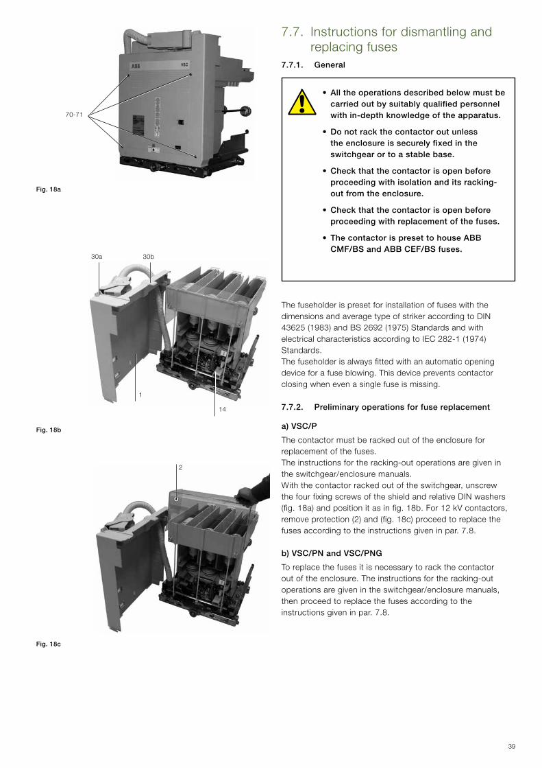
39
70-71
14
1
30a 30b
2
Fig. 18a
Fig. 18b
Fig. 18c
7.7. Instructions for dismantling and replacing fuses
7.7.1. General
• All the operations described below must be carried out by suitably qualified personnel with in-depth knowledge of the apparatus.
• Do not rack the contactor out unless the enclosure is securely fixed in the switchgear or to a stable base.
• Check that the contactor is open before proceeding with isolation and its racking-out from the enclosure.
• Check that the contactor is open before proceeding with replacement of the fuses.
• The contactor is preset to house ABB CMF/BS and ABB CEF/BS fuses.
The fuseholder is preset for installation of fuses with the dimensions and average type of striker according to DIN 43625(1983)andBS2692(1975)StandardsandwithelectricalcharacteristicsaccordingtoIEC282-1(1974)Standards. The fuseholder is always fitted with an automatic opening device for a fuse blowing. This device prevents contactor closing when even a single fuse is missing.
7.7.2. Preliminary operations for fuse replacement
a) VSC/P
The contactor must be racked out of the enclosure for replacement of the fuses. The instructions for the racking-out operations are given in the switchgear/enclosure manuals.Withthecontactorrackedoutoftheswitchgear,unscrewthe four fixing screws of the shield and relative DIN washers (fig.18a)andpositionitasinfig.18b.For12kVcontactors,removeprotection(2)and(fig.18c)proceedtoreplacethefuses according to the instructions given in par. 7.8.
b) VSC/PN and VSC/PNG
To replace the fuses it is necessary to rack the contactor out of the enclosure. The instructions for the racking-out operationsaregivenintheswitchgear/enclosuremanuals,then proceed to replace the fuses according to the instructions given in par. 7.8.
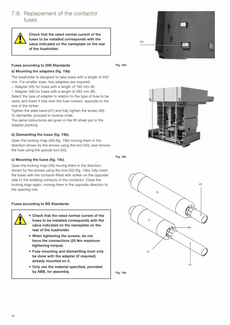
40
69
A
B
46
45
48
47
Fig. 18d
Fig. 18e
Fig. 19a
7.8. Replacement of the contactor fuses
Check that the rated normal current of the fuses to be installed corresponds with the value indicated on the nameplate on the rear of the fuseholder.
Fuses according to DIN Standards
a) Mounting the adapters (fig. 19a)
The fuseholder is designed to take fuses with a length of 442 mm.Forsmallersizes,twoadaptersarerequired:– Adapter(45)forfuseswithalengthof192mm(A)–Adapter(46)forfuseswithalengthof292mm(B).Select the type of adapter in relation to the type of fuse to be used,andinsertitfullyoverthefusecontact,oppositetotheone of the striker.Tightenthesteelband(47)andfullytightenthescrew(48).Todismantle,proceedinreverseorder.The same instructions are given in the Kit sheet put in the adapter packing.
b) Dismantling the fuses (fig. 19b)
Openthelockingrings(49)(fig.19b)movingtheminthedirectionshownbythearrowsusingthetool(50),andremovethefuseusingthespecialtool(50).
c) Mounting the fuses (fig. 19c)
Openthelockingrings(49)movingtheminthedirectionshownbythearrowsusingthetool(50)(fig.19b),fullyinsertthe fuses with the contacts fitted with striker on the opposite side to the isolating contacts of the contactor. Close the lockingringsagain,movingthemintheoppositedirectiontothe opening one.
Fuses according to BS Standards.
• Check that the rated normal current of the fuses to be installed corresponds with the value indicated on the nameplate on the rear of the fuseholder.
• When tightening the screws, do not force the connections (25 Nm maximum tightening torque).
• Fuse mounting and dismantling must only be done with the adapter (if required) already mounted on it.
• Only use the material specified, provided by ABB, for assembly.
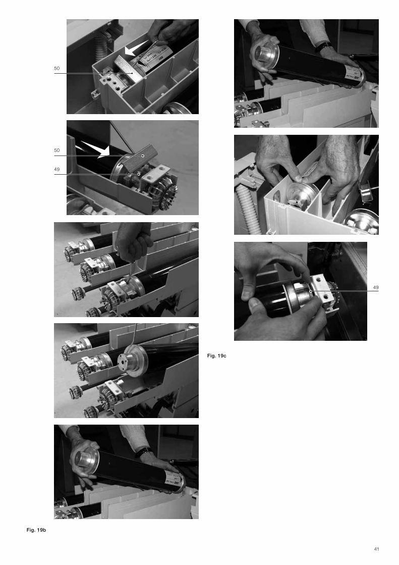
41
49
50
50
49
Fig. 19c
Fig. 19b
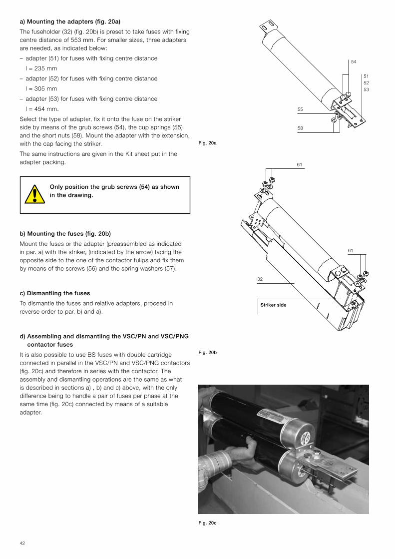
42
54
55
58
515253
32
61
61
Fig. 20a
Fig. 20b
a) Mounting the adapters (fig. 20a)
Thefuseholder(32)(fig.20b)ispresettotakefuseswithfixingcentredistanceof553mm.Forsmallersizes,threeadaptersareneeded,asindicatedbelow:
– adapter(51)forfuseswithfixingcentredistance
l = 235 mm
– adapter(52)forfuseswithfixingcentredistance
l = 305 mm
– adapter(53)forfuseswithfixingcentredistance
l = 454 mm.
Selectthetypeofadapter,fixitontothefuseonthestrikersidebymeansofthegrubscrews(54),thecupsprings(55)andtheshortnuts(58).Mounttheadapterwiththeextension,with the cap facing the striker.
The same instructions are given in the Kit sheet put in the adapter packing.
Only position the grub screws (54) as shown in the drawing.
b) Mounting the fuses (fig. 20b)
Mountthefusesortheadapter(preassembledasindicatedinpar.a)withthestriker,(indicatedbythearrow)facingtheopposite side to the one of the contactor tulips and fix them bymeansofthescrews(56)andthespringwashers(57).
c) Dismantling the fuses
Todismantlethefusesandrelativeadapters,proceedinreverse order to par. b) and a).
d) Assembling and dismantling the VSC/PN and VSC/PNG contactor fuses
It is also possible to use BS fuses with double cartridge connected in parallel in the VSC/PN and VSC/PNG contactors (fig.20c)andthereforeinserieswiththecontactor.Theassembly and dismantling operations are the same as what isdescribedinsectionsa),b)andc)above,withtheonlydifference being to handle a pair of fuses per phase at the sametime(fig.20c)connectedbymeansofasuitableadapter.
Striker side
Fig. 20c
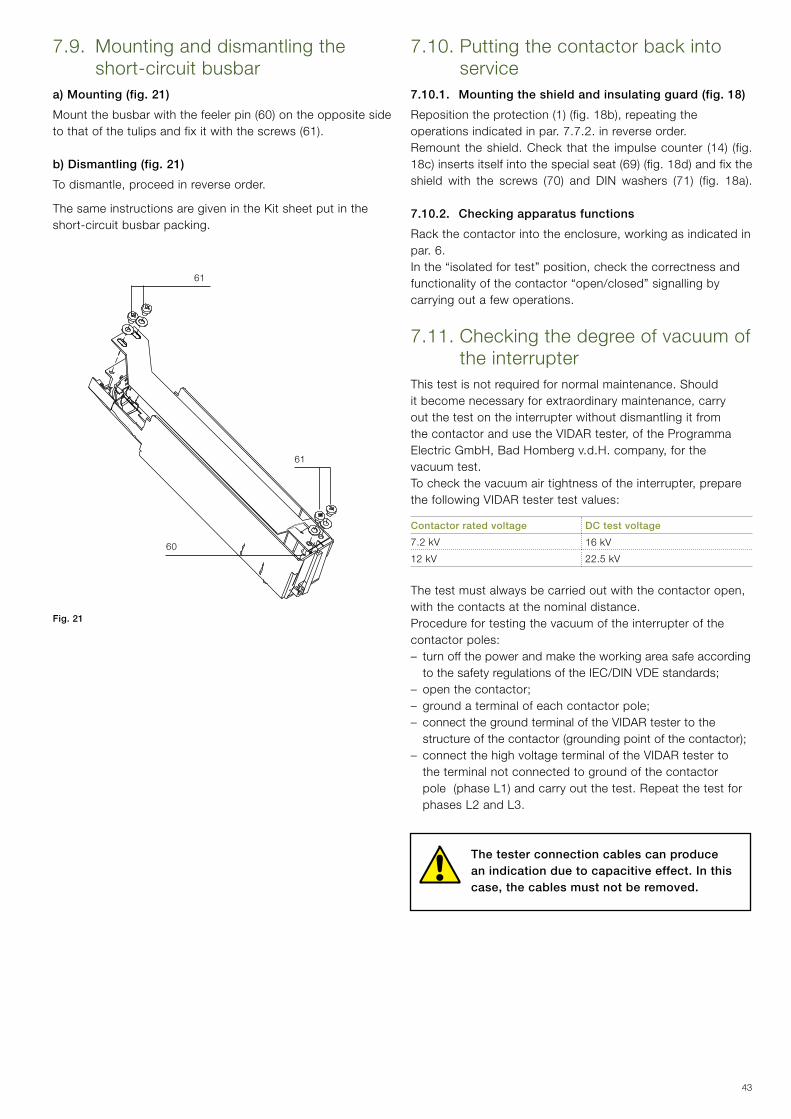
43
60
61
61
7.10. Putting the contactor back into service
7.10.1. Mounting the shield and insulating guard (fig. 18)
Repositiontheprotection(1)(fig.18b),repeatingtheoperations indicated in par. 7.7.2. in reverse order.Remount theshield.Check that the impulsecounter (14) (fig.18c)insertsitselfintothespecialseat(69)(fig.18d)andfixtheshield with the screws (70) and DIN washers (71) (fig. 18a).
7.10.2. Checking apparatus functions
Rackthecontactorintotheenclosure,workingasindicatedinpar. 6.Inthe“isolatedfortest”position,checkthecorrectnessandfunctionality of the contactor “open/closed” signalling by carrying out a few operations.
7.11. Checking the degree of vacuum of the interrupter
This test is not required for normal maintenance. Should itbecomenecessaryforextraordinarymaintenance,carryout the test on the interrupter without dismantling it from thecontactorandusetheVIDARtester,oftheProgrammaElectricGmbH,BadHombergv.d.H.company,forthevacuum test. Tocheckthevacuumairtightnessoftheinterrupter,preparethe following VIDAR tester test values:
Contactor rated voltage DC test voltage
7.2 kV 16 kV
12 kV 22.5 kV
Thetestmustalwaysbecarriedoutwiththecontactoropen,with the contacts at the nominal distance.Procedure for testing the vacuum of the interrupter of the contactor poles:– turn off the power and make the working area safe according
to the safety regulations of the IEC/DIN VDE standards;– open the contactor;– ground a terminal of each contactor pole;– connect the ground terminal of the VIDAR tester to the structureofthecontactor(groundingpointofthecontactor);
– connect the high voltage terminal of the VIDAR tester to the terminal not connected to ground of the contactor pole(phaseL1)andcarryoutthetest.Repeatthetestforphases L2 and L3.
The tester connection cables can produce an indication due to capacitive effect. In this case, the cables must not be removed.
Fig. 21
7.9. Mounting and dismantling the short-circuit busbar
a) Mounting (fig. 21)
Mountthebusbarwiththefeelerpin(60)ontheoppositesidetothatofthetulipsandfixitwiththescrews(61).
b) Dismantling (fig. 21)
Todismantle,proceedinreverseorder.
The same instructions are given in the Kit sheet put in the short-circuit busbar packing.

44
8. Spare parts and accessories8.1. List of spare parts–Vacuuminterrupterassembly(replacementtobecarriedout
by ABB)– MAC-R2 electronic card –Auxiliarycontacts(5normallyopenand/or5normally
closed)– Capacitor–Interfacingshaft(onlyfixedcontactors)–12kVinsulationpartitions(onlyfixedcontactors)–Actuatorassembly(replacementtobecarriedoutbyABB).– Operation counter– Fuses– Adapters for fuses–Fuseholders(replacementtobecarriedoutbyABB)– Tulip and jaw-type isolating contacts– Locking magnet in the truck– Microswitches.
Toordercontactorspareparts/accessories,refertotechnicalcatalogue 1VCP000165 and always state the following:– type of contactor– rated voltage of the contactor– rated normal current of the contactor– serial number of the contactor– rated voltage and frequency of any electrical spare parts.
Foravailabilityandtoorderspareparts,pleasecontactABBService.
9. Product quality and environmental protection
The pieces of apparatus are produced in compliance with the requirements of the international standards regarding quality andenvironmentalmanagementsystems.Inthesefields,theexcellent level is proved by availability of the ISO 9001 and ISO 14001 certificates.
End of product life
ABB is committed to respecting the requirements and laws for protection of the environment laid down according to the ISO 14001 Standard.
ABB offers its competency and collaboration in facilitating recycling and disposal of the products at the end of their life. It is always necessary to act in compliance with the local regulations in force for disposal of the products.
Methods of disposal
Disposal can either be carried out with thermal treatment in an incineration plant or by storage in special areas
Material Recommended method of disposal
Metals(Fe,Cu,Al,Ag,Zn,W,others) Separation and recycling
Thermoplasts Recycling or disposal
Epoxy resin Separation of metal parts and disposal of resin parts
Rubber Disposal
Dielectricoil(oilfortransformers) Recovery and recycling or disposal
Wood for packing Recycling or disposal
Aluminium foil for packing Recycling or disposal

45
For more information please contact:
ABB S.p.A. Power Products DivisionUnità Operativa Sace-MVVia Friuli, 4I-24044 DalmineTel.: +39 035 6952 111Fax: +39 035 6952 874E-mail: [email protected]
ABB AG Calor Emag Medium Voltage Products Oberhausener Strasse 33 D-40472 Ratingen Phone: +49(0)2102/12-1230, Fax: +49(0)2102/12-1916 E-mail: [email protected]
www.abb.com
The data and illustrations are not binding. We reserve the right to make changes without notice in the course of technical development of the product.
© Copyright 2014 ABB. All rights reserved. 1VC
D60
0943
-V52
07 -
Rev
. B, e
n - I
nstru
ctio
n M
anua
l - 2
014.
06 (V
-Con
tact
VS
C-F
-P-P
N-P
NG
) (gs
)