Embed Size (px)
Citation preview

MEDIUM VOLTAGESF6 GAS INSULATED
RING MAIN UNIT UP TO 15kV
AL-AHLEIA SWITCHGEAR CO. K.S.C.C.
Kuwait

Driven by a vision to pioneer, ASC has risen from its humble beginning more than 25 years ago of a sole factory for LV boards, to an organisation boasting of 11 factories managing LV & HV Switchgear, Transformers and Package Sub-stations, establishing itself as the largest power equipment manufacturer in the region.
ASC takes pride for being the leading local manufacturer of HV products, transformers and package S/S. Over time, ASC products have attained a reputation for quality, reliability as well as sustainability which gained recognition in the industrial sector in the Middle East.
All products have been developed inside the walls of the factory and will continue to improve, because progress stops once the spirit of pioneering is lost.

3
CONTENTS
1. Construction 4
2. Product Range 6
3. Technical Data 8
4. Salient Features 10
5. Optional Features 11
6. Safety Interlocks and Padlocking Provisions 14
7. Motorized Actuator and Telecontrol System 15
8. Protection of Transformer 16
9. Quality Assurance 18

4
CONSTRUCTION
Al-Ahleia make Ring Main Unit Type AR12 covers complete range of 12kV/15kV SF6 Gas Insulated switchgear with various built-in functions. These are available in various combinations according to customer needs. For different versions refer Table-A, B, C & D. These units are available in non-extensible or extensible construction. Ring main units can be constructed in various combinations with following switching functions:
• Ring switch and associated cable earthing switch.
• Transformer switch-fuse combination and associated earthing switch.
• Vacuum Circuit Breaker and 3-Position Disconnector combination.
Ring Main Unit Type AR12 is broadly categorized into two groups as indicated below:
• Ring main units with ring switches and switch-fuse unit for transformer control (versions given in Table-A & B).
• Ring main units with ring switches and Vacuum circuit breaker and 3-Position Disconnector for transformer control (versions given in Table-C & D).
Metering unit with CT, PT and Protection devices to align with above units can also be offered.
Ring Main Units are suitable for short circuit current levels up to:
• 25kA-1 sec for 12kV/50Hz system
• 20kA-3 sec for 12kV/50Hz system
• 21kA-1 sec for 15kV/60Hz system
Ring Main Unit Type AR12 meets relevant International Standards IEC 60265, IEC 62271-200, IEC 62271-100, IEC 62271-102 and IEC 62271-105.
Ring Main Units have been successfully tested for all type test duties for above mentioned ratings including Internal Arc Fault test as per relevant IEC (International Electrotechnical Commission) ensuring utmost safety of operators.
Ring Main Unit Switchgear comprises of one to four compact functional units such as: ring switch along with associated earthing switch, transformer switch-fuse along with associated earthing switch or circuit breaker with associated 3-Position Disconnector functions. The switching units together with other live parts and busbars (for versions given in Table - A, C & D) are contained in totally SF6 gas insulated gas-tight steel tank. High voltage connections are brought out through epoxy bushings. Circuit breaker is vacuum type and switches are load-break and fault-make type.

5
Make-break operation of ring switch and switch-fuse unit takes place in SF6 Gas (low pressure 0.05 to 0.3 Bar g). Pressure indicator is mounted on front panel of unit for ease of pressure monitoring.
Operating mechanism of all switches and VCB are simple and highly reliable. All operating mechanisms are located behind a front cover plate, displaying mimic diagram for various switching and earthing devices.
Spring-assisted fast acting manual close/open mechanisms are provided for the ring switch/ring earthing switch. Closing and opening is carried out by this fast acting mechanism. No energy is stored in springs at final position of switches (for versions given in Table - A & B)
Switch-Fuse unit is also operated by fast acting manual operating mechanism for manual closing operation. The fuses are normally equipped with striker pins which in the event of fault/abnormal current will operate and trip the switch-fuse unit. Local manual tripping facility is also provided.
Earthing contact can be closed and opened manually through specific operating shaft. Hinged lockable cover is provided for access to this shaft. A suitable common operating handle is provided to operate all switches.
VCB is provided with independent manual close/trip mechanism for normal operations. During conditions such as fault condition, VCB is tripped automatically with protection options described in subsequent pages. Protection options are independent of auxiliary supply. Manual tripping facility is also provided. 3-Position Disconnector switch connected with VCB facilitates isolation and earthing of transformer circuit. This disconnector switch is fully interlocked with VCB.
Load break switches of ring switch and transformer switch are fully interlocked with their respective earthing switches.
Suitable interlocks are provided for full safety of operating staff. These are described in details in subsequent part of this catalogue.
Switch and VCB position mechanical indicators are directly attached to their respective mechanisms, thus ensuring high degree of reliability.
Suitable weatherproof metal housings are provided to enclose SF6 gas tank, mechanisms, cable terminations and high voltage fuses where applicable. Fuse compartment and cable termination boxes are air insulated. Critical parts are made of stainless steel. Other parts are adequately protected against corrosion which could have caused by atmospheric effects.
Separate L.V compartment can be provided as required.

6
PRODUCT RANGE
Table - A: RMU versions with Switch-Fuse Units - Non-Extensible
Sl. No. Description Rating SLD Mounting
Overall Size
(Width x Depth x Height) in mm
Weight (kg)
(Approx.)
13 Way unit with 2 Ring switches and 1 Tr. Switch-Fuse
12kV, 50Hz, 20kA-3sec 15kV, 60Hz, 21kA-1sec - Ring Switch- 630A - Transformer Switch- 200A - Fuse- 200A
Free standing
or Transformer
mounting
W- 1000 D- 970 H- 1676
450
Table - B: RMU versions with Switch-Fuse Units - Extensible - Bottom Busbar
Sl. No. Description Rating SLD Mounting
Overall Size
(Width x Depth x Height) in mm
Weight (kg)
(Approx.)
11 Way unit with Ring switch
12kV, 50Hz, 20kA-3 sec, 630A
Free standing
W- 566 D- 1088 H- 1676
350
21 Way unit with Tr. Switch-Fuse
12kV, 50Hz, 20kA- 3sec, 200A
Free standing
W- 646 D- 1055 H- 1676
400
32 Way unit with Ring Switch and Tr. Switch-Fuse
12kV, 50Hz, 20kA -3sec - Ring Switch- 630A - Tr. Switch- 200A - Fuse- 200A
Free standing
W- 1206 D- 1088 H- 1676
450
44 Way unit with 2 Ring Switches and2 Tr. Switch-Fuse
12kV, 50Hz,20kA -3sec - Ring Switch - 630A - Tr. Switch- 200A - Fuse- 200A
Free standing
W- 2406 D- 1088 H- 1676
1500
54 Way unit with 3 Ring switches and 1 Tr. Switch-Fuse
12kV, 50Hz, 20kA -3sec - Ring Switch - 630A - Tr. Switch- 200A - Fuse- 200A
Free standing
or Transformer
mounting
W- 2326 D- 1088 H- 1676
1450
Notes:- - Fuses as required for Transformer Switch-Fuse units can be selected from Table-F.- Unit dimensions are without actuators.
- Busbar rating as required up to 1250A.

7
Table - C: RMU versions with Vacuum Circuit Breaker – Extensible
Sl. No. Description Ratings SLD Mounting
Overall Size (Width x Depth x
Height) in mm
Weight (kg)
(Approx.)
13 Way unit with 2 Ring switches and 1 VCB
12kV, 50Hz, 25kA -1sec 12KV, 50Hz, 20kA -3sec 15KV, 60Hz, 21kA -1sec - Ring Switch - 630A - VCB- 630A
Free standing
W- 1344 D- 713 H- 1695
650
2 3 Way unit with 3 Ring switches
12kV, 50Hz, 25kA -1sec 12kV, 50Hz, 20kA -3sec 15kV, 60Hz, 21kA -1sec - Ring Switch - 630A
Free standing
W- 1020 D- 713 H- 1695
600
34 Way unit with 2 Ring switches and 2 VCBs
12kV, 50Hz, 25kA -1sec 12kV, 50Hz, 20kA -3sec 15kV, 60Hz, 21kA -1sec - Ring Switch - 630A - VCB- 630A
Free standing
W- 1610 D- 713 H- 1695
900
44 Way unit with 3 Ring switches and 1 VCB
12kV, 50Hz, 25kA -1sec 12kV, 50Hz, 20kA -3sec 15kV, 60Hz, 21kA -1sec - Ring Switch - 630A - VCB- 630A
Free standing
W- 1455 D- 713 H- 1695
850
5 4 Way unit with 4 Ring switches
12kV, 50Hz, 25kA -1sec 12kV, 50Hz, 20kA -3sec 15kV, 60Hz, 21kA -1sec - Ring Switch - 630A
Free standing
W- 1303 D- 713 H- 1685
800
6 1 Way unit with VCB
12kV, 50Hz, 25kA -1sec 12kV, 50Hz, 20kA -3sec 15kV, 60Hz, 21kA -1sec - VCB- 630A
Free standing
W- 637 D- 713 H- 1695
250
7 1 Way unit with Ring switch
12kV, 50Hz, 25kA -1sec 12kV, 50Hz, 20kA -3sec 15KV, 60Hz, 21kA -1sec - Ring Switch - 630A
Free standing
W- 440 D- 713 H- 1695
200
8 Metering panel with PT and CT
12kV, 50Hz, 25kA -1sec 12kV, 50Hz, 20kA -3sec 15kV, 60Hz, 21kA -1sec
Free standing
W- 590 D- 713 H- 1695
-
Notes: - Unit dimensions are without actuators.- Busbar rating as required up to 1250A.

8
Table - D: RMU versions with Vacuum Circuit Breaker – Non-Extensible
Sl. No. Description Ratings SLD Mounting
Overall Size (Width x Depth x
Height) in mm
Weight (kg)
(Approx.)
13 Way unit with 2 Ring switches and 1 VCB
12kV, 50Hz, 25kA -1sec 12KV, 50Hz, 20kA -3sec 15KV, 60Hz, 21kA -1sec - Ring Switch - 630A - VCB- 630A
Free standing
W- 1344 D- 713 H- 1450
650
2 3 Way unit with 3 Ring switches
12kV, 50Hz, 25kA -1sec 12kV, 50Hz, 20kA -3sec 15kV, 60Hz, 21kA -1sec - Ring Switch - 630A
Free standing
W- 1020 D- 713 H- 1450
600
34 Way unit with 2 Ring switches and 2 VCBs
12kV, 50Hz, 25kA -1sec 12kV, 50Hz, 20kA -3sec 15kV, 60Hz, 21kA -1sec - Ring Switch - 630A - VCB- 630A
Free standing
W- 1610 D- 713 H- 1450
900
44 Way unit with 3 Ring switches and 1 VCB
12kV, 50Hz, 25kA -1sec 12kV, 50Hz, 20kA -3sec 15kV, 60Hz, 21kA -1sec - Ring Switch - 630A - VCB- 630A
Free standing
W- 1455 D- 713 H- 1450
850
5 4 Way unit with 4 Ring switches
12kV, 50Hz, 25kA -1sec 12kV, 50Hz, 20kA -3sec 15kV, 60Hz, 21kA -1sec - Ring Switch - 630A
Free standing
W- 1303 D- 713 H- 1450
800
Notes: - Unit dimensions are without actuators. - Busbar rating as required up to 1250A.
TECHNICAL DATATable – E
Ratings UnitRing Switch
(Load Break Switch)
Transformer Switch-Fuse
(Load Break Switch)
Vacuum Circuit Breaker
Type: ARRS12 Type: ARTS12 Type: AH12
Rated Voltage kV 12/15 12/15 12/15Rated Current (IEC Rating) A 630 200 630P.F. Withstand Voltage kV 28/38 28/38 28/38Impulse Withstand Voltage kVp 75/95 75/95 75/95Frequency Hz 50/60 50/60 50/60Breaking Current kA - 20/25 ** 25/20Mainly Active Load A 630 200 -Closed Loop Current (as per IEC 60265) A 630 - -Cable Charging Current (as per IEC 60265) A 25 25 -Short-time Withstand Current for 3 sec. kA 20 2.5 20Short-time Withstand Current for 1 sec. kA 25 3.15 25Rated Peak Withstand Current kAp 62.5 8.2 62.5Rated Peak Making Current kAp 62.5 50/65 ** 62.5Fuse Rating A -- Up to 160 -Rated Busbar Current (IEC Rating) A Up to 1250Minimum operating SF6 Gas Pressure Bar g 0.05
** Prospective value, the actual current being limited by fuse.

9
3 Way RMU Incorporating 2 Ring Switch and 1 Switch Fuse Unit (Provision for Manual Operation Only)
View with Front Door and Fuse
Compartment Door Open
Side View Showing Cable Terminals

10
SALIENT FEATURES
• Suitable for Indoor and Outdoor use.
• Available in Extensible or Non-Extensible versions.
• Free standing or Transformer mounted.
• Full protection from external environment.
• Low operating gas pressure.
• Common operating handle for all the switches (for versions given in Table - A & B).
• Gas Pressure Indicator and Gas refilling valve.
• Built-in Earthing Switches for ring cables and Transformer.
• Earthing switch for earthing both sides of H.T. Fuse.
• Built-in cable testing provision.
• No external test plugs are required. Power cable on the ring circuits can be tested without disconnecting from terminal bushing (for versions given in Table - A, C & D).
• Extension of existing RMU switchboard is possible without handling of SF6 gas (for versions given in Table - B & C).
• High degree of operator safety due to:
- Backside located Pressure relief diaphragm (Bursting Disc).
- Live parts contained within SF6 gas insulated earthed steel tank.
- Padlockable switches.
- Mimic diagram on panel front with indicators to facilitate correct operations.
- Complete interlocking facility provided for:
* Switches with respective earthing switches.
* Cable testing device with respective ring switches.
* Fuse removal with transformer switch.
• Blown Fuse Indicator.

11
OPTIONAL FEATURES
Mostly required features for functions of RMU are included in standard design. However, following additional features can be fitted to the unit on demand:
1. Voltage indication unit: This facility is in-built in cable bushing which makes it possible to check the presence or absence of voltage in cable, through LED voltage indicators fitted on the unit front panel.
2. Earth fault indication: This provides the indication of an earth fault current in Ring cable system. This facilitates that location of fault can be isolated and power supply can be restored quickly through healthy sections.
3. Short circuit indication: These are used to indicate short circuit fault in cable section. This facilitates that location of fault can be isolated and power supply can be restored quickly through healthy sections.
4. Motorized Linear actuator: For electrical operation from remote, motorized linear actuators can be provided as ‘built-in’ or ‘add-on’ feature. For details refer Page No.15.
5. Cable test plugs: Separate cable test plugs for testing power cable can be supplied.
6. Trip coil for Transformer control: This can be provided for tripping of transformer switch-fuse/circuit breaker.
7. Overcurrent / Earth fault protection: This can be provided where circuit breaker is used for transformer control.
8. Phase comparator: This can be used in conjunction with voltage indicating device for checking status of phase angle of two ring connections.
9. Anti-reflex operating handle: This facilitates the required delay in any attempt to bring the switch to ‘OFF’ condition from ‘ON’ condition during making operation.
10. Pressure switch: This is used for indication/alarm of gas over pressure or low pressure at local/remote location.
11. Cable termination kits: XLPE/PILC cable termination kits suitable for cables up to 300mm².
12. Key interlocks: Mechanical key interlocks can be provided to interlock between various feeders of multi function RMUs.
13. Operation counter: To have a record of number of operations switches have performed, operation counters can be provided.
14. Auxiliary intertrip relay with indication: To discriminate the tripping commands given by the transformer integrated safety device.
12
Fuse ReplacementManual Operation of Ring Switch
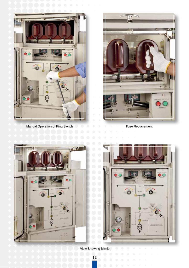
View Showing Mimic

13
Manual Operation of Ring Switch
View with Front Door and Cable Compartment Door Open
View with Front Door Open

14
SAFETY INTERLOCKS AND PADLOCKING PROVISIONS
All versions of Ring Main Unit Type AR12 are fully interlocked to avoid mal-operation, thus ensuring the safety of operating persons. Following are the interlocks provided on switch positions to prevent incorrect operations. Additional interlocks can be considered as per specific requirements.
A) RMU with Ring switches and Transformer Switch-Fuse Unit
Ring Switch and Earthing Switch
- It is not possible to operate the ring switch directly from ‘ON’ to ‘EARTH ON’ and vice versa.
- It is not possible to operate the cable testing device unless the associated ring earthing switch is in ‘EARTH ON’ position.
- It is not possible to operate the ring earthing switch from ‘EARTH ON’ to ‘OFF’ position with the associated cable testing device in the ‘DISENGAGED’ position.
Transformer Switch-Fuse and Earthing Switch
- It is not possible to operate the transformer switch directly from ‘ON’ to ‘EARTH ON’ and vice versa.
- It is not possible to open the door of the fuse compartment for getting access to H.T fuses unless the transformer earthing switch is in ‘EARTH ON’ position.
- It is not possible to operate the transformer switch or the transformer earthing switch while fuse compartment door is open.
- It is not possible to operate the transformer switch to ‘ON’ position with a blown fuse in circuit.
B) RMU with Vacuum Circuit Breaker and 3-Position Disconnector
Ring Switch and Earthing Switch
- It is not possible to operate the ring switch directly from ‘ON’ to ‘EARTH ON’ and vice versa.
- It is not possible to disconnect earthing link unless ring earthing switch is in earth position.
- It is not possible to operate a ring earthing switch from ‘EARTH ON’ to ‘OFF’ position unless earthing link is restored.
- It is not possible to open the cable box cover unless the ring earthing switch is in ‘EARTH ON’ position.
- It is not possible to operate the ring earthing switch from ‘EARTH ON’ position unless cable box cover is closed.
Vacuum Circuit Breaker and 3-Position Disconnector
- It is not possible to operate 3-Position Disconnector switch from ‘READY TO EARTH’ to ‘ON’ or vice versa unless the circuit breaker is in ‘OFF’ position.
- It is not possible to open the cable box cover unless the 3-Position Disconnector is in ‘READY TO EARTH’ position.
- It is not possible to operate the 3-Position Disconnector from ‘READY TO EARTH’ position unless the cable box cover is closed.

15
- It is not possible to access/operate the VCB if handle of 3-Position Disconnector is inserted or disconnector is in intermediate position i.e. between ‘ON’, ‘OFF’ or ‘READY TO EARTH’ position.
Padlocking Provisions
For RMU with 2 Ring Switches and with 1 Transformer Switch-Fuse
Padlocking facilities are provided at 5 locations in Ring Main Unit i.e. 1 No. for unit front door handle, 3 Nos. for switch operating shaft access covers and 1 No. for cover for gas filling valve.
For RMU with 2 Ring Switches and with 1 VCB
Padlocking facilities are provided at 5 locations in Ring Main Unit i.e. 2 Nos. for ring switch operating shaft access covers, 1 No. for spring charging handle, 1 No. for 3-Position Disconnector and 1 No. for cover for gas filling valve.
Additional padlocking facilities can be considered on demand.
MOTORIZED ACTUATOR AND TELECONTROL SYSTEM
Motorized Actuators can be provided for the Ring switches and Transformer switches. If required Ring Main Units can also be supplied with switches having provision to add these actuators at a later date at site.
The actuators will allow the switches to be controlled from remote for simple ON/OFF operations or Automation functions by using suitable Remote Telecontrol System. Besides allowing user-defined switching functions, Remote Telecontrol System can also perform measurement, recording and display of necessary analog data and can indicate the status of switches at Remote Control Stations.
The automation can be extended to hook-up several RMUs or integrate with existing SCADA systems.
Fig-1: Typical for 3 Way RMU of version 1 of Table-A
ACTUATOR FORL.H RING SWITCH
ACTUATOR FORR.H RING SWITCH
ACTUATOR FORTRANSFORMER SWITCH-FUSE
MOUNTING ARRANGEMENT OF ACTUATOR WITH SWITCHES.
TRANSFORMER SWITCH-FUSE SHAFT
RING SWITCHSHAFT
CLOSING OPERATION

16
PROTECTION OF TRANSFORMER
A) When Vacuum Circuit Breaker is controlling the transformer
When short circuit protection / earth fault protection has to be provided for transformers of various rating, two options are available. In both the options auxiliary power is not required.
Option-1: Protection with Time Limit Fuse Links (refer schematic drawing for Option-1).
Protection CTs are fitted on HT cables running between vacuum circuit breaker and transformer. Time Limit Fuse links are mounted in LV compartment which will short the CT secondary terminals as shown in schematic drawing. Thus current flowing through Electronic unit is negligible, under normal healthy conditions.
In the event of abnormality (i.e. faulty conditions), fuse will blow-off and resultant current will pass through the electronic circuit. Electronic circuit in turn will give trip command to VCB. Fuse link characteristics selection is based on transformer rating, LV side protection and inrush current of the transformer.
Option-2: Protection with relay (refer schematic drawing for Option-2)
In place of fuses, normally close contacts of IDMT over current/earth fault relay, short the CT secondary giving effect as fuses. Relay characteristics selection is carried out, based on transformer rating, inrush current, L.V side protection and short circuit withstand of transformer.
Fig-2 : Scheme for Option-1 Fig-3 : Scheme for Option-2
B) When Switch-Fuse unit is controlling transformer
When transformer is to be protected by Switch-Fuse combination, fuse selection can be made in line with relevant standards.
The rating of the fuses protecting the transformer depends among other things, on operating voltage, transformer rating and thermal characteristics of fuses.
Under mentioned selection table gives the ratings (in Amp) of fuses (DIN standards) which can be installed in Type AR12 Ring Main Units.
VCB TRIPCOIL
RELAY
3-POSITIONDISCONNECTOR
BUSBAR
CTs (AS MOUNTEDON CABLE)
TRANSFORMER
TRANSFORMER PROTECTION SYSTEM

17View Showing Mimic and Relay
3 Way RMU Incorporating 2 Ring Switch and 1 VCB with Provision for Motorised Operation

18
Table – F
Transformer use
Operating voltage
(kV)
Transformer rating (kVA)
25 50 100 125 160 200 250 315 400 500 630 800 1000 1250 1600
for -25°≤θ≤40°C 3.3 16 20 40 50 63 63 80 80 100 160 - - - - -
6.6 10 16 20 25 31.5 40 50 50 63 80 80 100 125 160 -
11 6.3 10 16 20 25 25 31.5 40 40 63 63 63 80 100 125
13.8 6.3 6.3 10 16 20 20 25 31.5 40 40 50 63 63 100 125
15 6.3 6.3 10 16 16 20 25 31.5 31.5 40 50 63 63 80 125
for 40°<θ≤55°C 3.3 16 20 40 50 63 63 80 100 125 160 - - - - -
6.6 10 16 20 25 31.5 40 50 50 63 80 100 125 160 - -
11 6.3 10 16 20 25 25 31.5 40 40 63 63 80 100 125 160
13.8 6.3 6.3 10 16 20 20 25 31.5 40 50 50 63 80 100 160
15 6.3 6.3 10 16 16 20 25 31.5 31.5 40 50 63 80 100 125
Notes: - Fuse ratings given above are for reference. Rating of fuse to be finalized based on specific applications. - Fuses are with strikers for operating transformer switch through linkage. - Fuses to other standards such as IEC can also be considered on demand.
Quality Assurance
Al-Ahleia has the unique distinction to be the first Kuwaiti Company to be awarded the prestigious BSEN ISO 9001, Quality Management Certificate in recognition of its high quality in product / customer services and its excellent Quality Assurance System.
Comprehensive Quality Control is carried out at every stage from incoming materials up to the end product. Group of Engineers and skilled manpower with the help of latest testing equipments ensure compliance to the customer requirements and IEC/BS Specification.
Al-Ahleia Ring Main Units are tested for short circuit tests at KEMA Laboratories, Netherlands.

19
View with Front Door and Fuse
Compartment Door Open
View with Front Door Open
3 Way RMU Incorporating 2 Ring Switch and 1 Switch Fuse Unit with Provision for Motorised Operation

Nov. 2010 2587 / 05
Copy Rights © 2010 - Al-Ahleia Switchgear Co.All Rights Reserved
GPS Location
29° 13’ 59.40” N - 48° 00’ 59.76” E