Embed Size (px)
Citation preview
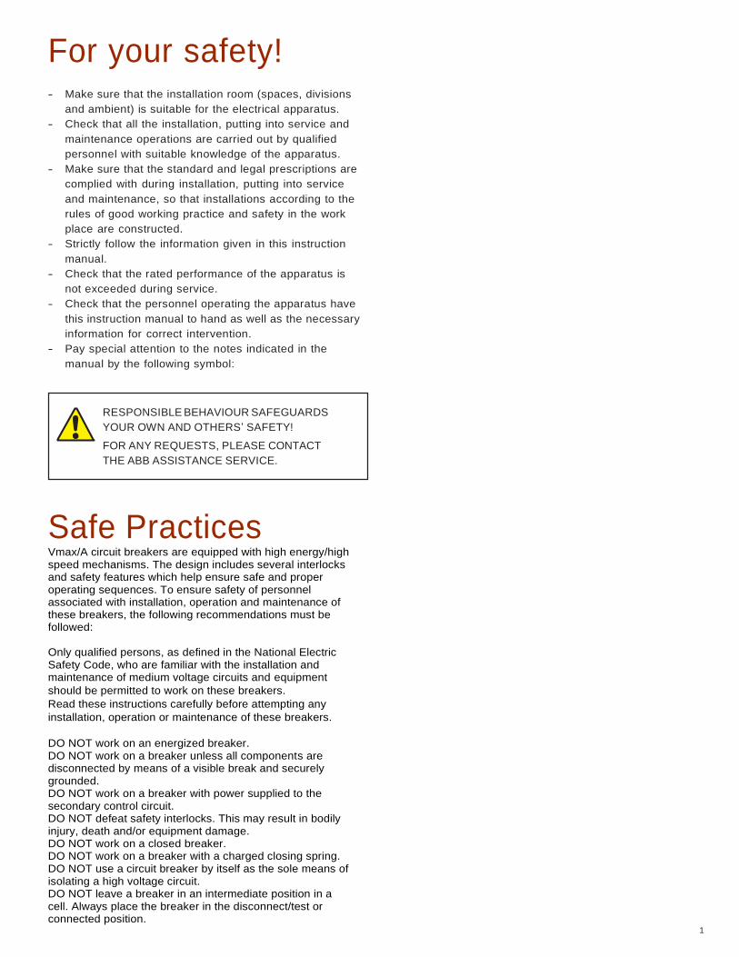
Vmax/A Medium voltage vacuum circuit breaker ANSI: 4.76kV-15 kV; 1200-2000 A; 31.5 kA
Medium Voltage Products
Vmax/A Medium voltage vacuum circuit breaker ANSI: 4.76kV-15 kV; 1200-2000 A; 31.5 kA
For your safety! 1
1. Foreword 2
1.1. Introduction 2
1.2. Environmental protection program 2
1.3. Vacuum interrupter quenching principle 2
1.4. Information on this booklet 3
1.5. Drawout 3
1.6. Application of the X-ray emission standards 3
2. Introduction and safe practices 4
2.1. Introduction 4
2.2. Safe practices 4
2.3. Standard and regulations 5
3. Receiving, handling, and storage 6
3.1. Receiving 6
3.2. Handling 7
3.3. Storage 8
4. Description 9
4.1. General 9
4.2. Reference Standards 9
4.3. Withdrawable Vmax Outline 10
4.4. Characteristics of the electrical accessories 12
4.5. Preliminary operations 13
4.6. Putting into service 14
5. Operation, installation and maintenance 20
5.1. Interlocks 20
5.2. Maintenance 21
5.3. Truck 26
6. Spare parts and accessories 28
6.1. List of spare parts 28
7. Overall dimensions 29
8. Electric circuit diagram 31
9. Product quality and environmental protection 32
1
For your safety! - Make sure that the installation room (spaces, divisions
and ambient) is suitable for the electrical apparatus.
- Check that all the installation, putting into service and
maintenance operations are carried out by qualified
personnel with suitable knowledge of the apparatus.
- Make sure that the standard and legal prescriptions are
complied with during installation, putting into service
and maintenance, so that installations according to the
rules of good working practice and safety in the work
place are constructed.
- Strictly follow the information given in this instruction
manual.
- Check that the rated performance of the apparatus is
not exceeded during service.
- Check that the personnel operating the apparatus have
this instruction manual to hand as well as the necessary
information for correct intervention.
- Pay special attention to the notes indicated in the
manual by the following symbol:
RESPONSIBLE BEHAVIOUR SAFEGUARDS
YOUR OWN AND OTHERS’ SAFETY!
FOR ANY REQUESTS, PLEASE CONTACT
THE ABB ASSISTANCE SERVICE.
Safe Practices Vmax/A circuit breakers are equipped with high energy/high speed mechanisms. The design includes several interlocks and safety features which help ensure safe and proper operating sequences. To ensure safety of personnel associated with installation, operation and maintenance of these breakers, the following recommendations must be followed: Only qualified persons, as defined in the National Electric Safety Code, who are familiar with the installation and maintenance of medium voltage circuits and equipment
should be permitted to work on these breakers. Read these instructions carefully before attempting any
installation, operation or maintenance of these breakers. DO NOT work on an energized breaker. DO NOT work on a breaker unless all components are disconnected by means of a visible break and securely grounded. DO NOT work on a breaker with power supplied to the secondary control circuit. DO NOT defeat safety interlocks. This may result in bodily injury, death and/or equipment damage. DO NOT work on a closed breaker. DO NOT work on a breaker with a charged closing spring. DO NOT use a circuit breaker by itself as the sole means of isolating a high voltage circuit. DO NOT leave a breaker in an intermediate position in a cell. Always place the breaker in the disconnect/test or connected position.
2
1. Foreword
1.1 Introduction
This publication contains the information needed to install
medium voltage Vmax/A circuit breakers and put them into
service. For correct use of the product, please read it carefully.
Like all the apparatus we manufacture, the Vmax/A circuit-
breakers are designed for different installation configurations.
However, they do allow further technical and construction
modifications (at the customer’s request) to adapt to special
installation requirements.
For this reason, the information given below may sometimes not
contain instructions concerning special configurations.
Apart from this manual, it is therefore always necessary to
consult the latest technical documentation (circuit and wiring
diagrams, assembly and installation drawings, any protection
coordination studies, etc.), especially regarding any variants
requested in relation to the standardized configurations.
For example, the racking and interlock sections do not apply to
the fixed mount breaker styles. All information in this booklet
was current at the time of printing. Unless otherwise noted, all
references in this booklet are determined by viewing the circuit-
breaker from the front.
Only use original spare parts for maintenance operations.
For further information, please also see the technical catalogue
of the circuit breaker.
1.2 Environmental protection program
The Vmax/A circuit breakers are manufactured in accordance with
the ISO 14000 Standards (Guidelines for environmental
management).
The production processes are carried out in compliance with the
Standards for environmental protection in terms of reduction in
energy consumption as well as in raw materials and production of
waste materials. All this is thanks to the medium voltage apparatus
manufacturing facility environmental management system.
1.3 Vacuum interrupter quenching principle
Due to the extremely low static interrupter chamber pressure of 10-
4 to 10-8 mbar, only a relatively small contact gap is required to
achieve a high dielectric strength. The vacuum arc is extinguished
on one of the first natural current zeroes. Due to the small contact
gap, high conductivity of the metal vapor plasma, and short arcing
time, the associated arc energy is extremely low, which has
advantageous effects on the life of the contacts and thus on that of
the vacuum interrupters.
3
1.4 Information in this booklet
This booklet provides information for the Vmax/A circuit breakers
as described below. Not all sections of the bulletin apply to all
types of Vmax/A circuit breakers. All information in this booklet
was current at the time of printing. Unless otherwise noted, all
references in this booklet are determined by viewing the circuit-
breaker from the front.
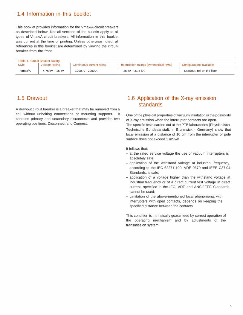
Table 1. Circuit Breaker Rating Style Voltage Rating Continuous current rating Interruption ratings (symmetrical RMS) Configurations available
Vmax/A 4.76 kV – 15 kV 1200 A – 2000 A 25 kA – 31.5 kA Drawout, roll on the floor
1.5 Drawout
A drawout circuit breaker is a breaker that may be removed from a
cell without unbolting connections or mounting supports. It
contains primary and secondary disconnects and provides two
operating positions: Disconnect and Connect.
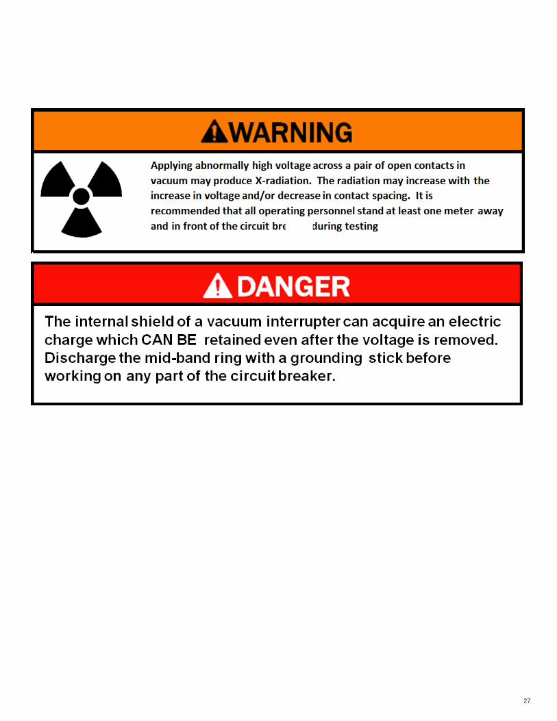
1.6 Application of the X-ray emission standards
One of the physical properties of vacuum insulation is the possibility
of X-ray emission when the interrupter contacts are open.
The specific tests carried out at the PTB laboratories (Physikalisch-
Technische Bundesanstalt, in Brunswick - Germany) show that
local emission at a distance of 10 cm from the interrupter or pole
surface does not exceed 1 mSv/h.
It follows that:
– at the rated service voltage the use of vacuum interrupters is
absolutely safe;
– application of the withstand voltage at industrial frequency,
according to the IEC 62271-100, VDE 0670 and IEEE C37.04
Standards, is safe;
– application of a voltage higher than the withstand voltage at
industrial frequency or of a direct current test voltage in direct
current, specified in the IEC, VDE and ANSI/IEEE Standards,
cannot be used;
– Limitation of the above-mentioned local phenomena, with
interrupters with open contacts, depends on keeping the
specified distance between the contacts.
This condition is intrinsically guaranteed by correct operation of
the operating mechanism and by adjustments of the
transmission system.
4
2. Introduction and safe practices
2.1. Introduction
The purpose of this manual is to provide instructions for
unpacking, storage, installation, operation, and maintenance for
Vmax/A vacuum circuit breakers. This manual should be
carefully read and used as a guide during installation, initial
operation, and maintenance.
The specific ratings of each model circuit breaker are listed on
the individual nameplates. The Vmax/A circuit breakers are
protective devices. As such, they are maximum rated devices.
In no event should they be applied outside of their nameplate
ratings.
WARNING
2.2. Safe practices
Vmax/A circuit breakers are equipped with high energy / high
speed mechanisms. The design includes several interlocks and
safety features which help ensure safe and proper operating
sequences. To ensure safety of personnel associated with
installation, operation, and maintenance of these circuit breakers,
the following recommendations must be followed.
Only qualified persons, as defined in the National Electric Safety
Code, who are familiar with the installation and maintenance of
medium voltage circuits and equipment should be permitted to work
on these circuit breakers
Read these instructions carefully before attempting any
installation, operation, or maintenance of these power circuit-
breakers.
- Do not work on an energized circuit breaker.
- Do not work on a circuit breaker unless all components are disconnected by means of a visible break and securely grounded.
- Do not work on a circuit breaker with power supplied to the secondary control circuit.
- Do not defeat safety interlocks. This may result in bodily injury, death and/or equipment damage.
- Do not work on a closed circuit breaker.
- Do not work on a circuit breaker with charged energy (springs charged).
- Do not use a circuit breaker by itself as the sole means of isolating a high voltage circuit.
- Do not leave a circuit breaker in an intermediate position in a cell. Always place the circuit breaker in the disconnect or connect position.
CE
5
To avoid the risk of corrosion or other damage in areas: – with a high level of humidity, and/or – with rapid and large temperature variations, take appropriate steps
(for example, by using suitable electric heaters) to prevent condensation
phenomena.
2.3. Standard and regulations
2.3.1. Fabrication
The Vmax/A circuit breakers conform to the following
standards:
- IEEE C37.04
- DIN VDE 0670, part 104, and IEC 62271-100
- DIN VDE 0847, part 4, and IEC 61000-4
2.3.2. Installation and operation
For assembly and operation, please refer to the relevant
regulations, and in particular to:
- ANSI / NFPA70
- NEC
2.3.3. Service conditions
Normal service conditions
Follow the recommendations in the IEC 62271-1 and 62271-
100 Standards. In more detail:
IEEE C37.09
IEEE C37.54 – C37.20.2.
Ambient temperature
Maximum + 40 °C / 104 °F
Average maximum over 24 hours + 35 °C / 95 °F
Minimum for indoor installation - 30 °C/ -22 °F
Humidity
The average value of the relative humidity, measured for a period longer than
24 hours, must not exceed 95%
The average value of the pressure of the water vapor without condensation,
measured for a period longer than 24 hours, must not exceed 2.2 kPa.
The average value of the relative humidity, measured for a period longer than
1 month, must not exceed 90%.
The average value of the pressure of the water vapor, measured for a period
longer than 1 month, must not exceed 1.8 kPa.
Altitude
< 1000 (3300 ft.) m above sea level.
For application above 1000m (3300 ft.) C37.20.2 is applicable
Climate
For special installation requirements or other operating
conditions, please contact ABB.
6
3. Receiving, handling, and storage
Vmax/A circuit breakers are subject to complete factory production tests and inspection prior to packaging and shipment. The shipping
package is designed to provide reasonable protection during shipment and to provide convenient handling. Accessories such as opening
handles and racking handles are shipped separately from the circuit breaker. The circuit breaker is shipped in special packing, in the open
position. Each piece of apparatus is protected by a plastic cover to prevent any infiltration of water during the loading and unloading stages
and to keep the dust off during storage.
3.1. Receiving
On receipt, check the state of the apparatus, integrity of the
packing and correspondence with the nameplate data with what
is specified in the order confirmation and in the accompanying
shipping notes.
Also make sure that all the materials described in the shipping
notes are included in the supply.
Should any damage or irregularity be noted in the supply on
unpacking, notify ABB (directly or through the agent or supplier)
as soon as possible and in any case within five days of receipt.
The apparatus is only supplied with the accessories specified at
the time of ordering and validated in the order confirmation sent
by ABB.
The accompanying documents inserted in the shipping packing
are:
– Instruction manual (this document)
– Test certification
– Identification label
– Copy of the shipping documents
– Electric wiring diagram.
Other documents which are sent prior to shipment of the
apparatus are:
– Order confirmation
– Original shipping advice notes
– Any drawings or documents referring to special
configurations/conditions.
Immediately upon receipt of the circuit breaker(s), examine the
carton(s) to determine if any damage or loss was sustained during
transit. If damage or indication of rough handling is evident, file a
damage claim at once with the carrier and promptly notify the
nearest district office. ABB is not responsible for damage to goods
which occur after delivery. However, ABB will lend assistance if
notified of claims. Use care in unpacking the circuit breaker to
avoid damaging any circuit breaker parts.
Unpack circuit breakers as soon as possible after receipt. If
unpacking is delayed, difficulty may be experienced in making
a claim for damages not evident upon receipt. Check the
contents of each carton against the packing list before
discarding any packing material. If any discrepancy is
discovered, promptly notify the nearest district office.
Information specifying the purchase order number, carton
number, and part numbers of damaged or missing parts should
accompany the claim.
7
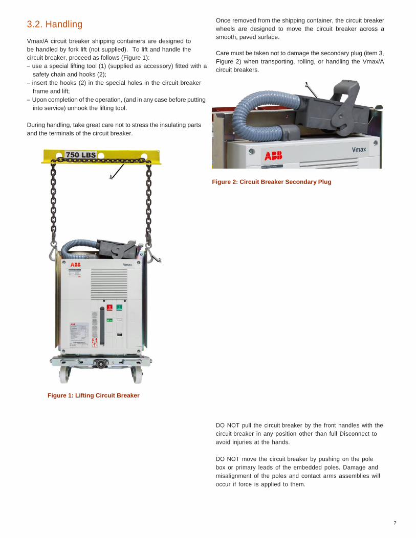
3.2. Handling
Vmax/A circuit breaker shipping containers are designed to
be handled by fork lift (not supplied). To lift and handle the
circuit breaker, proceed as follows (Figure 1):
– use a special lifting tool (1) (supplied as accessory) fitted with a
safety chain and hooks (2);
– insert the hooks (2) in the special holes in the circuit breaker
frame and lift;
– Upon completion of the operation, (and in any case before putting
into service) unhook the lifting tool.
During handling, take great care not to stress the insulating parts
and the terminals of the circuit breaker.
Once removed from the shipping container, the circuit breaker
wheels are designed to move the circuit breaker across a
smooth, paved surface.
Care must be taken not to damage the secondary plug (item 3,
Figure 2) when transporting, rolling, or handling the Vmax/A
circuit breakers.
Figure 2: Circuit Breaker Secondary Plug
Figure 1: Lifting Circuit Breaker
DO NOT pull the circuit breaker by the front handles with the
circuit breaker in any position other than full Disconnect to
avoid injuries at the hands.
DO NOT move the circuit breaker by pushing on the pole
box or primary leads of the embedded poles. Damage and
misalignment of the poles and contact arms assemblies will
occur if force is applied to them.
8
3.3. Storage
On receipt the apparatus must be carefully unpacked and
checked as described in Checking on receipt. If immediate
installation is not possible, the packing must be replaced, using
the original material supplied. Insert special hygroscopic
substances inside the packing, using at least one standard
packet per piece of apparatus. Should the original packing not be
available and immediate installation is not possible, store in a
covered, well-ventilated, dry, dust-free, non-corrosive ambient,
away from any flammable materials and at a temperature
between – 30°C ( -22°F ) and + 45°C ( +113°F ).
Circuit breakers should be installed in their permanent location
as soon as possible. If the circuit breakers are not placed in
service for some time, it is advisable to provide adequate means
of environmental protection. This may be done by keeping the
circuit breaker in its original shipping container and storing it in a
warm, dry, and uncontaminated atmosphere. The circuit-
breakers should be stored to minimize condensation. Moisture
can cause deterioration of metal parts and high voltage
insulation.
Prior to storage of the circuit breaker, verification should be made
that it is free from shipping damage and is in satisfactory
operating condition.
CAUTION
9
4. Description
4.1. General
The Vmax series of circuit breakers are pieces of
apparatus under vacuum for indoor installation; for the
electrical performances, please refer to the
corresponding technical catalogue. For special
installation requirements, please contact ABB. The
following version is available:
Withdrawable for ABB RELIAGEAR ND Switchgear
4.2. Reference Standards
The Vmax circuit breakers conform to the IEC 62271-100, IEEE
C37.04 – C37.54 – C37.09 – C37.55 standards and those of
major industrialized countries.
10
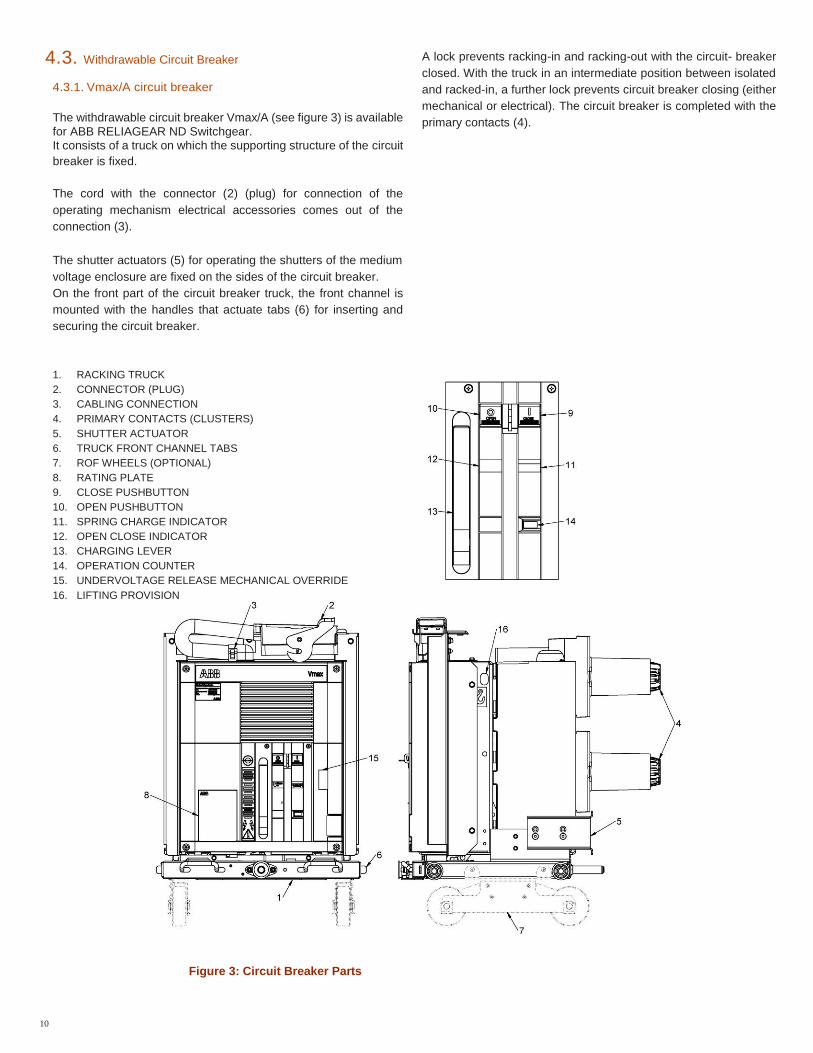
4.3. Withdrawable Circuit Breaker
4.3.1. Vmax/A circuit breaker
The withdrawable circuit breaker Vmax/A (see figure 3) is available
for ABB RELIAGEAR ND Switchgear. It consists of a truck on which the supporting structure of the circuit
breaker is fixed.
The cord with the connector (2) (plug) for connection of the
operating mechanism electrical accessories comes out of the
connection (3).
The shutter actuators (5) for operating the shutters of the medium
voltage enclosure are fixed on the sides of the circuit breaker.
On the front part of the circuit breaker truck, the front channel is
mounted with the handles that actuate tabs (6) for inserting and
securing the circuit breaker.
A lock prevents racking-in and racking-out with the circuit- breaker
closed. With the truck in an intermediate position between isolated
and racked-in, a further lock prevents circuit breaker closing (either
mechanical or electrical). The circuit breaker is completed with the
primary contacts (4).
1. RACKING TRUCK
2. CONNECTOR (PLUG)
3. CABLING CONNECTION
4. PRIMARY CONTACTS (CLUSTERS)
5. SHUTTER ACTUATOR
6. TRUCK FRONT CHANNEL TABS
7. ROF WHEELS (OPTIONAL)
8. RATING PLATE
9. CLOSE PUSHBUTTON
10. OPEN PUSHBUTTON
11. SPRING CHARGE INDICATOR
12. OPEN CLOSE INDICATOR
13. CHARGING LEVER
14. OPERATION COUNTER
15. UNDERVOLTAGE RELEASE MECHANICAL OVERRIDE
16. LIFTING PROVISION
Figure 3: Circuit Breaker Parts
11
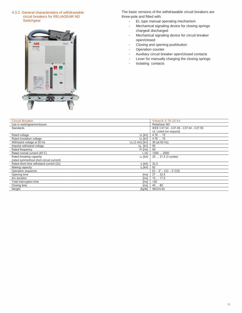
4.3.2. General characteristics of withdrawable circuit breakers for RELIAGEAR ND Switchgear
The basic versions of the withdrawable circuit breakers are
three-pole and fitted with:
- EL type manual operating mechanism
- Mechanical signaling device for closing springs
charged/ discharged
- Mechanical signaling device for circuit breaker
open/closed
- Closing and opening pushbutton
- Operation counter
- Auxiliary circuit breaker open/closed contacts
- Lever for manually charging the closing springs
- Isolating contacts
Circuit Breaker Vmax/A 4.76-15 kV
Use in switchgear/enclosure ReliaGear ND
Standards IEEE C37.54 - C37.09 - C37.04 - C37.55 UL Listed (on request)
Rated voltage Ur [kV] 4.76 … 15
Rated insulation voltage Us [kV] 4.76 … 15
Withstand voltage at 50 Hz Ud (1 min) [kV] 36 (at 60 Hz)
Impulse withstand voltage Up [kV] 95
Rated frequency Fr [Hz] 60
Rated normal current (40˚C) Ir [A] 1200 … 2000
Rated breaking capacity (rated symmetrical short-circuit current)
Isc [kA] 25 … 31.5 (3 cycles)
Rated-short time withstand current (2s) Ik [kA] 31.5
Making capacity Ip [kA] 82
Operation sequence [O - .3” – CO – 3’ CO]
Opening time [ms] 27 … 32.5
Arc duration [ms] 10 … 17.5
Total interruption time [ms] <50
Closing time [ms] 45 … 80
Weight [kg/lb] 98/215.60
12
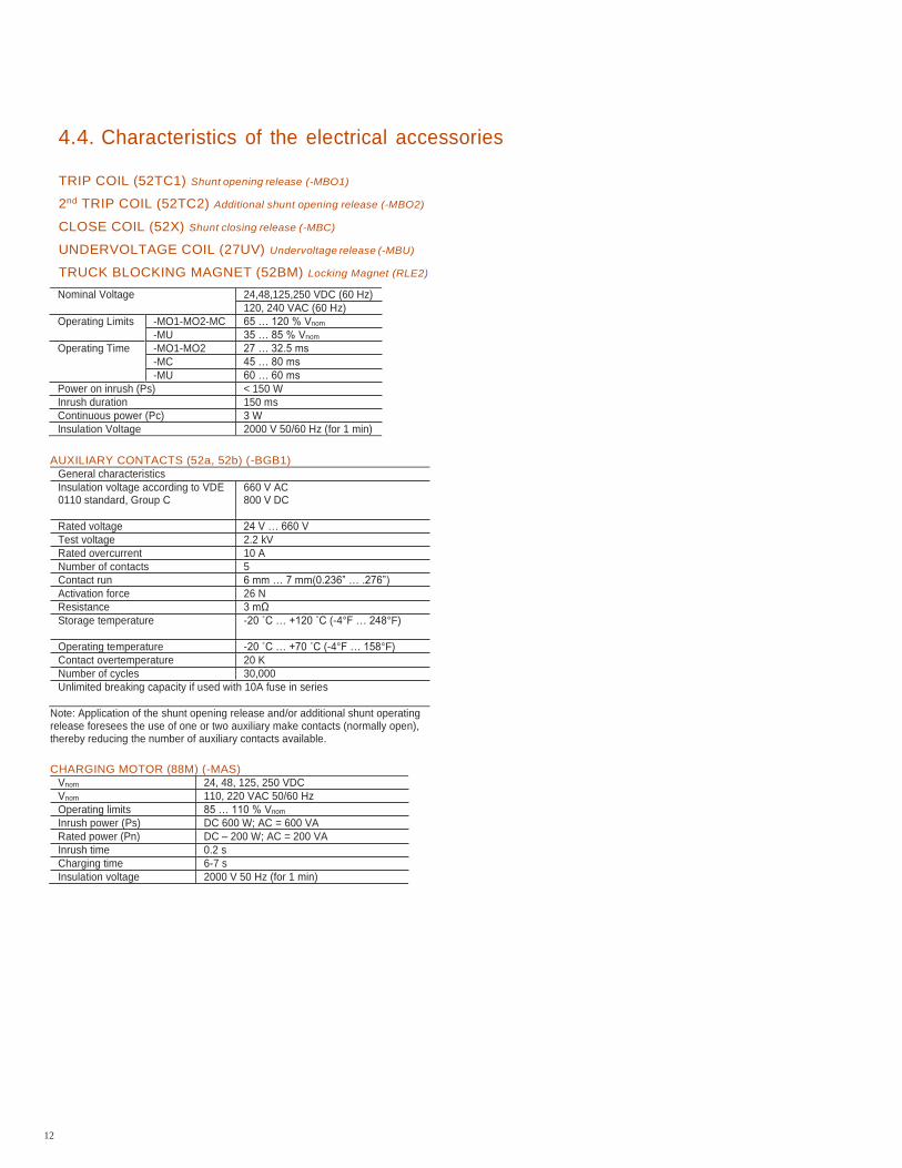
4.4. Characteristics of the electrical accessories
TRIP COIL (52TC1) Shunt opening release (-MBO1)
2nd TRIP COIL (52TC2) Additional shunt opening release (-MBO2)
CLOSE COIL (52X) Shunt closing release (-MBC)
UNDERVOLTAGE COIL (27UV) Undervoltage release (-MBU)
TRUCK BLOCKING MAGNET (52BM) Locking Magnet (RLE2)
Nominal Voltage 24,48,125,250 VDC (60 Hz)
120, 240 VAC (60 Hz)
Operating Limits -MO1-MO2-MC 65 … 120 % Vnom
-MU 35 … 85 % Vnom
Operating Time -MO1-MO2 27 … 32.5 ms
-MC 45 … 80 ms
-MU 60 … 60 ms
Power on inrush (Ps) < 150 W
Inrush duration 150 ms
Continuous power (Pc) 3 W
Insulation Voltage 2000 V 50/60 Hz (for 1 min)
AUXILIARY CONTACTS (52a, 52b) (-BGB1)
General characteristics
Insulation voltage according to VDE 0110 standard, Group C
660 V AC 800 V DC
Rated voltage 24 V … 660 V
Test voltage 2.2 kV
Rated overcurrent 10 A
Number of contacts 5
Contact run 6 mm … 7 mm(0.236” … .276”)
Activation force 26 N
Resistance 3 mΩ
Storage temperature -20 ˚C … +120 ˚C (-4°F … 248°F)
Operating temperature -20 ˚C … +70 ˚C (-4°F … 158°F)
Contact overtemperature 20 K
Number of cycles 30,000
Unlimited breaking capacity if used with 10A fuse in series
Note: Application of the shunt opening release and/or additional shunt operating release foresees the use of one or two auxiliary make contacts (normally open), thereby reducing the number of auxiliary contacts available.
CHARGING MOTOR (88M) (-MAS)
Vnom 24, 48, 125, 250 VDC
Vnom 110, 220 VAC 50/60 Hz
Operating limits 85 … 110 % Vnom
Inrush power (Ps) DC 600 W; AC = 600 VA
Rated power (Pn) DC – 200 W; AC = 200 VA
Inrush time 0.2 s
Charging time 6-7 s
Insulation voltage 2000 V 50 Hz (for 1 min)
13
4.5. Preliminary operations
Clean the insulating parts with clean dry cloth.
Check that the top and bottom terminals are clean and free of
any deformation caused by shocks received during transport
or storage.
4.5.1. Insertion and removal of withdrawable circuit
breaker
This section describes the process for inserting the breaker
into the disconnect position of the switchgear and the removal
of the circuit breaker from the disconnect position. Racking of
the circuit breaker to and from the connect and disconnect
position is covered in the following section.
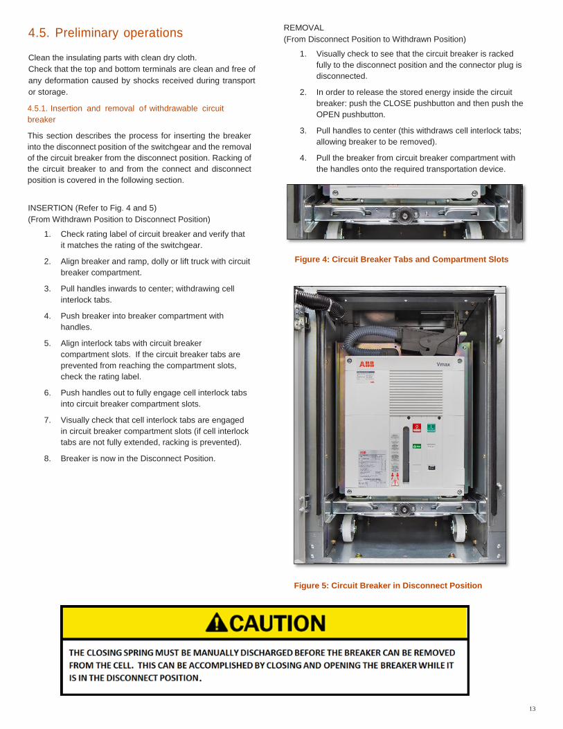
INSERTION (Refer to Fig. 4 and 5)
(From Withdrawn Position to Disconnect Position)
1. Check rating label of circuit breaker and verify that
it matches the rating of the switchgear.
2. Align breaker and ramp, dolly or lift truck with circuit
breaker compartment.
3. Pull handles inwards to center; withdrawing cell
interlock tabs.
4. Push breaker into breaker compartment with
handles.
5. Align interlock tabs with circuit breaker
compartment slots. If the circuit breaker tabs are
prevented from reaching the compartment slots,
check the rating label.
6. Push handles out to fully engage cell interlock tabs
into circuit breaker compartment slots.
7. Visually check that cell interlock tabs are engaged
in circuit breaker compartment slots (if cell interlock
tabs are not fully extended, racking is prevented).
8. Breaker is now in the Disconnect Position.
REMOVAL
(From Disconnect Position to Withdrawn Position)
1. Visually check to see that the circuit breaker is racked
fully to the disconnect position and the connector plug is
disconnected.
2. In order to release the stored energy inside the circuit
breaker: push the CLOSE pushbutton and then push the
OPEN pushbutton.
3. Pull handles to center (this withdraws cell interlock tabs;
allowing breaker to be removed).
4. Pull the breaker from circuit breaker compartment with
the handles onto the required transportation device.
Figure 4: Circuit Breaker Tabs and Compartment Slots
Figure 5: Circuit Breaker in Disconnect Position
14
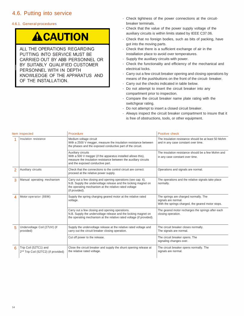
tem inspected Procedure Positive check
1 Insulation resistance Medium voltage circuit
With a 2500 V megger, measure the insulation resistance between
the phases and the exposed conductive part of the circuit.
The insulation resistance should be at least 50 Mohm
and in any case constant over time.
Auxiliary circuits
With a 500 V megger (if the apparatus installed allows this),
measure the insulation resistance between the auxiliary circuits
and the exposed conductive part.
The insulation resistance should be a few Mohm and
in any case constant over time.
2 Auxiliary circuits Check that the connections to the control circuit are correct:
proceed at the relative power supply.
Operations and signals are normal.
3 Manual operating mechanism Carry out a few closing and opening operations (see cap. 6).
N.B. Supply the undervoltage release and the locking magnet on
the operating mechanism at the relative rated voltage
(if provided).
The operations and the relative signals take place
normally.
4 Motor operator (88M) Supply the spring charging geared motor at the relative rated
voltage.
The springs are charged normally. The
signals are normal.
With the springs charged, the geared motor stops.
Carry out a few closing and opening operations.
N.B. Supply the undervoltage release and the locking magnet on
the operating mechanism at the relative rated voltage (if provided).
The geared motor recharges the springs after each
closing operation.
5 Undervoltage Coil (27UV) (if
provided) Supply the undervoltage release at the relative rated voltage and
carry out the circuit breaker closing operation.
The circuit breaker closes normally.
The signals are normal.
Cut off power to the release. The circuit breaker opens. The
signaling changes over.
6 Trip Coil (52TC1) and
2nd Trip Coil (52TC2) (if provided)
Close the circuit breaker and supply the shunt opening release at
the relative rated voltage.
The circuit breaker opens normally. The
signals are normal.
4.6. Putting into service
4.6.1. General procedures
- Check tightness of the power connections at the circuit-
breaker terminals.
- Check that the value of the power supply voltage of the
auxiliary circuits is within limits stated by IEEE C37.06.
- Check that no foreign bodies, such as bits of packing, have
got into the moving parts.
- Check that there is a sufficient exchange of air in the
installation place to avoid over temperatures.
- Supply the auxiliary circuits with power.
- Check the functionality and efficiency of the mechanical and
electrical locks.
- Carry out a few circuit breaker opening and closing operations by
means of the pushbuttons on the front of the circuit- breaker.
- Carry out the checks indicated in table below.
- Do not attempt to insert the circuit breaker into any
compartment prior to inspection.
- Compare the circuit breaker name plate rating with the
switchgear rating.
- Do not attempt to insert a closed circuit breaker.
- Always inspect the circuit breaker compartment to insure that it
is free of obstructions, tools, or other equipment.
I
15
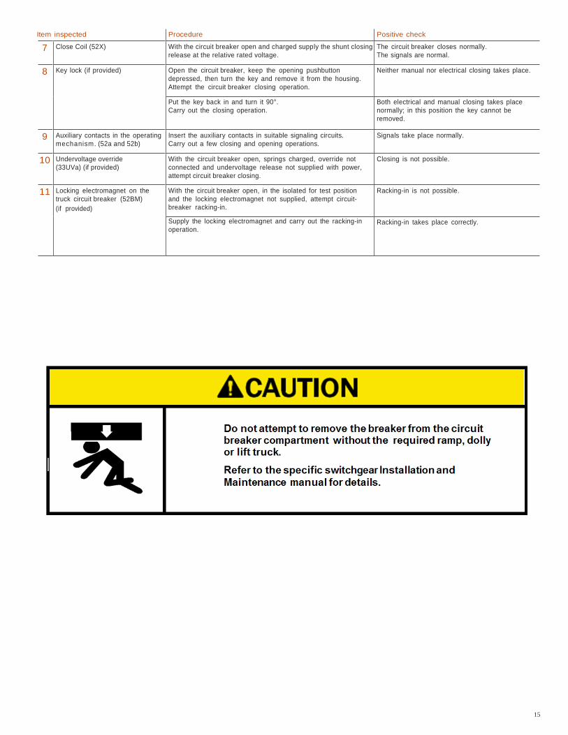
tem inspected Procedure Positive check
7 Close Coil (52X) With the circuit breaker open and charged supply the shunt closing
release at the relative rated voltage. The circuit breaker closes normally.
The signals are normal.
8 Key lock (if provided) Open the circuit breaker, keep the opening pushbutton
depressed, then turn the key and remove it from the housing.
Attempt the circuit breaker closing operation.
Neither manual nor electrical closing takes place.
Put the key back in and turn it 90°.
Carry out the closing operation. Both electrical and manual closing takes place
normally; in this position the key cannot be
removed.
9 Auxiliary contacts in the operating
mechanism. (52a and 52b) Insert the auxiliary contacts in suitable signaling circuits.
Carry out a few closing and opening operations. Signals take place normally.
10 Undervoltage override
(33UVa) (if provided) With the circuit breaker open, springs charged, override not
connected and undervoltage release not supplied with power,
attempt circuit breaker closing.
Closing is not possible.
11 Locking electromagnet on the
truck circuit breaker (52BM)
(if provided)
With the circuit breaker open, in the isolated for test position
and the locking electromagnet not supplied, attempt circuit-
breaker racking-in.
Racking-in is not possible.
Supply the locking electromagnet and carry out the racking-in
operation. Racking-in takes place correctly.
I
16
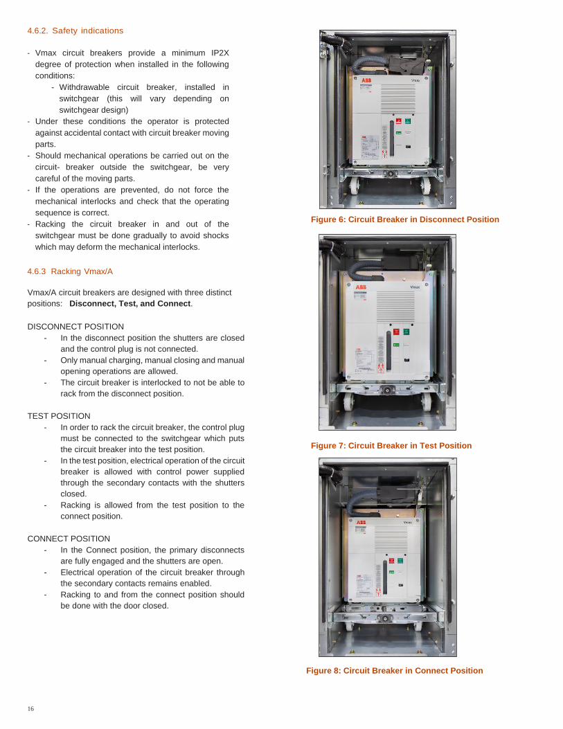
4.6.2. Safety indications
- Vmax circuit breakers provide a minimum IP2X
degree of protection when installed in the following
conditions:
- Withdrawable circuit breaker, installed in
switchgear (this will vary depending on
switchgear design)
- Under these conditions the operator is protected
against accidental contact with circuit breaker moving
parts.
- Should mechanical operations be carried out on the
circuit- breaker outside the switchgear, be very
careful of the moving parts.
- If the operations are prevented, do not force the
mechanical interlocks and check that the operating
sequence is correct.
- Racking the circuit breaker in and out of the
switchgear must be done gradually to avoid shocks
which may deform the mechanical interlocks.
4.6.3 Racking Vmax/A
Vmax/A circuit breakers are designed with three distinct
positions: Disconnect, Test, and Connect.
DISCONNECT POSITION
- In the disconnect position the shutters are closed
and the control plug is not connected.
- Only manual charging, manual closing and manual
opening operations are allowed.
- The circuit breaker is interlocked to not be able to
rack from the disconnect position.
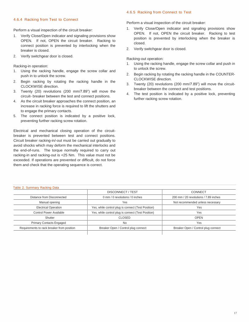
TEST POSITION
- In order to rack the circuit breaker, the control plug
must be connected to the switchgear which puts
the circuit breaker into the test position.
- In the test position, electrical operation of the circuit
breaker is allowed with control power supplied
through the secondary contacts with the shutters
closed.
- Racking is allowed from the test position to the
connect position.
CONNECT POSITION
- In the Connect position, the primary disconnects
are fully engaged and the shutters are open.
- Electrical operation of the circuit breaker through
the secondary contacts remains enabled.
- Racking to and from the connect position should
be done with the door closed.
Figure 6: Circuit Breaker in Disconnect Position
Figure 7: Circuit Breaker in Test Position
Figure 8: Circuit Breaker in Connect Position
17
4.6.4 Racking from Test to Connect
Perform a visual inspection of the circuit breaker:
1. Verify Close/Open indicator and signaling provisions show
OPEN. If not, OPEN the circuit breaker. Racking to
connect position is prevented by interlocking when the
breaker is closed.
2. Verify switchgear door is closed.
Racking-in operation:
1. Using the racking handle, engage the screw collar and
push in to unlock the screw.
2. Begin racking by rotating the racking handle in the
CLOCKWISE direction.
3. Twenty (20) revolutions (200 mm/7.89”) will move the
circuit- breaker between the test and connect positions.
4. As the circuit breaker approaches the connect position, an
increase in racking force is required to lift the shutters and
to engage the primary contacts.
5. The connect position is indicated by a positive lock,
preventing further racking screw rotation.
Electrical and mechanical closing operation of the circuit-
breaker is prevented between test and connect positions.
Circuit breaker racking-in/-out must be carried out gradually to
avoid shocks which may deform the mechanical interlocks and
the end-of-runs. The torque normally required to carry out
racking-in and racking-out is <25 Nm. This value must not be
exceeded. If operations are prevented or difficult, do not force
them and check that the operating sequence is correct.
4.6.5 Racking from Connect to Test
Perform a visual inspection of the circuit breaker:
1. Verify Close/Open indicator and signaling provisions show
OPEN. If not, OPEN the circuit breaker. Racking to test
position is prevented by interlocking when the breaker is
closed.
2. Verify switchgear door is closed.
Racking-out operation:
1. Using the racking handle, engage the screw collar and push in
to unlock the screw.
2. Begin racking by rotating the racking handle in the COUNTER-
CLOCKWISE direction.
3. Twenty (20) revolutions (200 mm/7.89”) will move the circuit-
breaker between the connect and test positions.
4. The test position is indicated by a positive lock, preventing
further racking screw rotation.
Table 2. Summary Racking Data
DISCONNECT / TEST CONNECT Distance from Disconnected 0 mm / 0 revolutions / 0 inches 200 mm / 20 revolutions / 7.89 inches
Manual opening Yes Not recommended unless necessary
Electrical Operation Yes, while control plug is connect (Test Position) Yes
Control Power Available Yes, while control plug is connect (Test Position) Yes
Shutter CLOSED OPEN
Primary Contacts Engaged No Yes
Requirements to rack breaker from position Breaker Open / Control plug connect Breaker Open / Control plug connect
18
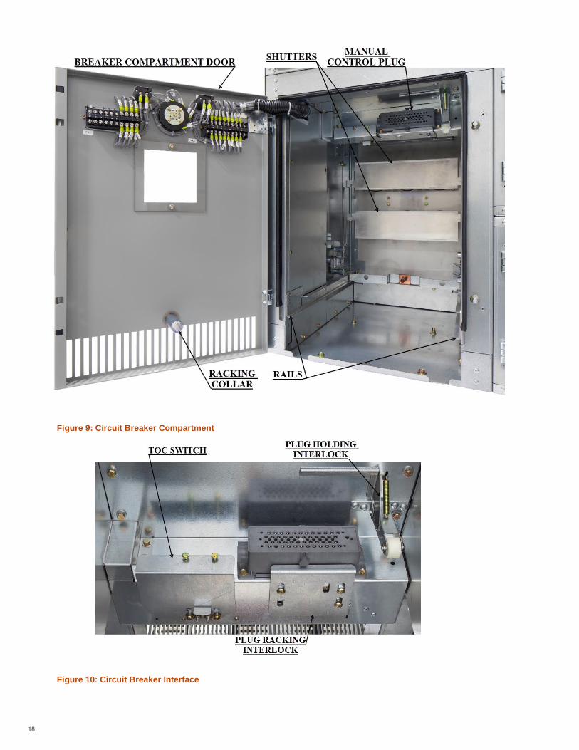
Figure 9: Circuit Breaker Compartment
Figure 10: Circuit Breaker Interface
19
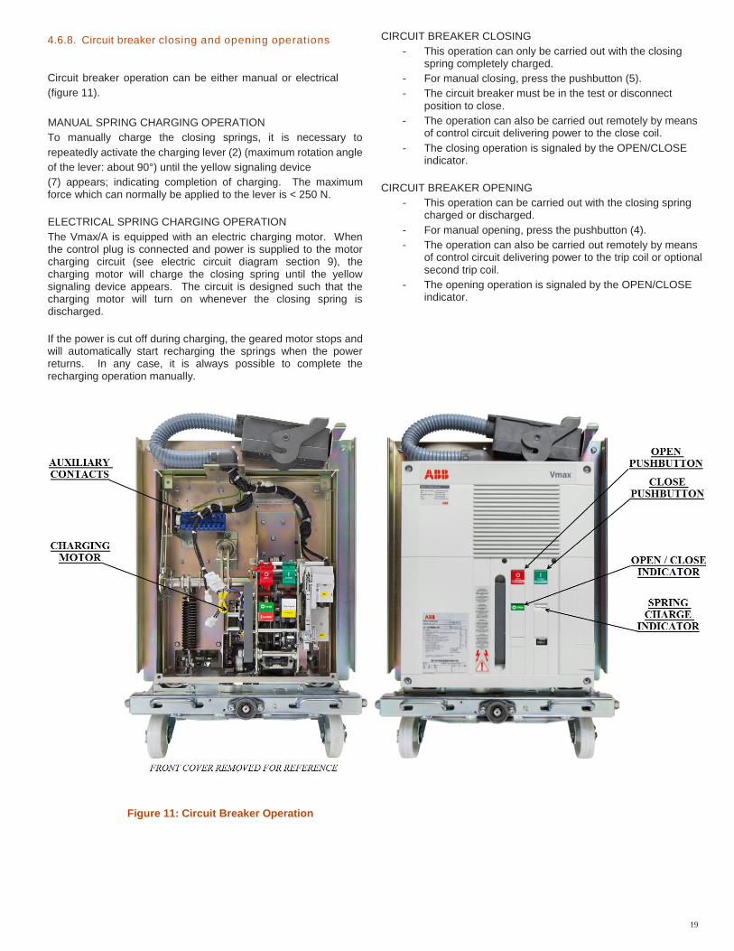
4.6.8. Circuit breaker closing and opening operations
Circuit breaker operation can be either manual or electrical
(figure 11).
MANUAL SPRING CHARGING OPERATION
To manually charge the closing springs, it is necessary to
repeatedly activate the charging lever (2) (maximum rotation angle
of the lever: about 90°) until the yellow signaling device
(7) appears; indicating completion of charging. The maximum force which can normally be applied to the lever is < 250 N.
ELECTRICAL SPRING CHARGING OPERATION
The Vmax/A is equipped with an electric charging motor. When the control plug is connected and power is supplied to the motor charging circuit (see electric circuit diagram section 9), the charging motor will charge the closing spring until the yellow signaling device appears. The circuit is designed such that the charging motor will turn on whenever the closing spring is discharged.
If the power is cut off during charging, the geared motor stops and will automatically start recharging the springs when the power returns. In any case, it is always possible to complete the recharging operation manually.
CIRCUIT BREAKER CLOSING
- This operation can only be carried out with the closing spring completely charged.
- For manual closing, press the pushbutton (5).
- The circuit breaker must be in the test or disconnect position to close.
- The operation can also be carried out remotely by means of control circuit delivering power to the close coil.
- The closing operation is signaled by the OPEN/CLOSE indicator.
CIRCUIT BREAKER OPENING
- This operation can be carried out with the closing spring charged or discharged.
- For manual opening, press the pushbutton (4).
- The operation can also be carried out remotely by means of control circuit delivering power to the trip coil or optional second trip coil.
- The opening operation is signaled by the OPEN/CLOSE indicator.
Figure 11: Circuit Breaker Operation
20
5. Operation, installation and maintenance
5.1. Interlocks These interlocks are provided to prevent incorrect operations and/or malfunctions. The interlocks are the following:
5.1.1. Interference blocking
A mechanical interference blocking in the circuit breaker
compartment prevents under rated circuit breakers from being
inserted into higher rated compartments. The code plate rating
includes continuous current, interrupting current, and maximum
voltage.
5.1.2. Racking Interlocks
- The withdrawable truck can only be moved from the test/
- Isolated position to the connected position (and vice
versa) if the circuit breaker is open (this means that first
of all the circuit- breaker must be opened).
- The circuit breaker can only be closed if the
withdrawable truck is exactly in the defined
disconnected, test or in the connected position.
- The circuit breaker can only be racked when the
breaker is OPEN.
- The switchgear is provided with devices which
only allow connection and disconnection of the
plug connector in the test position.
- The circuit breaker can only be racked when the
control plug is connected.
- The handles in the front channel of the truck can
only be pulled in when the circuit breaker is in the
disconnect position.
5.1.3. Spring Charge Interlock
- When the circuit breaker is racked to the test position
and then the plug is disconnected, the handles in the
front channel of the truck are blocked because the
closing spring is charged.
- In order to remove the circuit breaker from the
compartment, the closing spring must be discharged by
manually pushing the CLOSE pushbutton.
- After closing, there is still stored energy in the opening
spring. So the breaker should be opened by pushing
the OPEN pushbutton. Otherwise, the pulling of the
handles will OPEN the circuit breaker.
21
5.2. Maintenance
Vmax circuit breakers are designed for a minimum amount of
maintenance. Circuit breakers in a clean, non-corrosive
environment require only annual inspection. Dusty or
corrosive environments require inspection more often at the
discretion of the user. Following each interrupted fault
inspection is required.
DO NOT work on an energized circuit breaker.
DO NOT work on a circuit breaker unless all of the components
are disconnected by means of a visible break and securely
grounded.
DO NOT work on a circuit breaker with power supplied to the
secondary control circuit.
DO NOT defeat safety interlocks. This may result in bodily injury,
death and/or equipment damage.
DO NOT work on a closed circuit breaker.
DO NOT work on a circuit breaker with charged energy. (Springs)
DO NOT use a circuit breaker by itself as the sole means of
isolating a high voltage circuit.
DO NOT leave a circuit breaker in an intermediate position in a
cell. Always have the circuit breaker in the Disconnect or
Connect position.
DO NOT put a circuit breaker of a lower rating into a
switchgear compartment of a higher rating.
5.2.1. General
Vacuum circuit breakers are characterized by simple, sturdy
construction and long life.
The drive is maintenance-free for its whole operating life and
only requires functional inspections.
The vacuum interrupters are maintenance-free for their whole
operating life.
Vacuum interruption does not produce harmful effects even
when there are frequent trips at the rated and short-circuit
current.
The servicing interventions and their aim depend on the
environmental conditions, on the sequence of operations and
on the trips under short-circuit.
Note
For maintenance work, respect the following Standards:
– the relative specifications indicated in the “Standards and
Specifications” chapter;
– regulations for safety in the workplace indicated in the
“Putting into service and operations” chapter;
– Regulations and specifications of the country where the
apparatus is installed.
The maintenance operations can only be carried out by trained
personnel who respect all the safety regulations. Furthermore, is
recommended that ABB service personnel should be called in, at
least to check the service performances, and for any repair work.
During maintenance work, turn the power supply off and put the
apparatus under safe conditions.
22
5.2.2. Mechanism
The mechanism requires visual inspection of hardware,
lubrication and operation during routine inspection.
Remove the front cover by unfastening the screws and set the
front cover aside, securing the hardware.
Always lubricate the working surface of the moving parts. Verify
lubrication on the connections of the actuator and lever arm.
Remove any grease on the circuit breaker frame. Use only
grease Isoflex Topas NB52 (ABB No GCE0007249P100 1Pt.
can). If the grease becomes caked and dirty, remove with a
clean cloth and reapply lubrication.
Maintenance operations are aimed at ensuring trouble-free
operation of the apparatus for the longest possible time.
In accordance with what is specified in IEEE C37.04 - C37.54 -
C37.09 - C37.55 Standards and NETA Standards, the following
operations must be carried out:
Inspection: Determination of the actual conditions
Servicing: Measures to be taken to maintain the specification
conditions
Repairs: Measures to be taken to restore the specification
conditions.
DANGER
5.2.3. Operating life
All vacuum circuit breakers are characterized by simple, sturdy
construction and long useful life. Frequent operation of the service
and short-circuit currents does not negatively affect the degree of
vacuum of the interrupters.
Typical useful life expectancy of a Vmax vacuum circuit breaker
is determined by the following factors:
- Vacuum interrupter, maintenance free up to 10,000 mechanical
operating cycles.
- drive with mechanical actuator, maintenance free under
normal service conditions
- up to 10,000 operating cycles for all the circuit breakers with
breaking capacity up to 31.5 kA and rated current up to 2000A
- indication of ON/OFF position up to 10,000 operating cycles
- Withdrawable truck: up to 500 handling operations can be
carried out in the case of normal activation and with regular
inspections.
The data on the useful life are in principle applied to all the
components which are not directly affected by the operator.
The useful life of the manually activated components (movement
of the withdrawable truck, etc.) can vary according to the type of
handling.
The time intervals and amount of maintenance are determined
by environmental agents, by the frequency of operation and by
the number of trip operations under short-circuit.
.
23
5.2.4. Inspections and functional tests
Interruption devices in general
– Carry out regular inspections to check that the interruption
devices are in good condition.
– Inspection at fixed intervals can be waived when the
apparatus is permanently monitored by qualified personnel.
– Above all, the checks must include a visual inspection to check
for any contamination, traces of corrosion and electrical
discharge phenomena.
– Carry out more frequent inspections when there are unusual
operating conditions (including adverse climatic conditions)
and in the case of environmental pollution (e.g. heavy
contamination or an atmosphere with aggressive agents).
– Visual examination of the isolating contacts:
Turning the system of contacts alternately is recommended, in
order to keep the internal surface of the contact areas clean.
The contact areas must be cleaned if there are signs of
overheating (discolored surface).
– If any conditions are found, appropriate servicing measures
must be taken (see the paragraph on “Servicing).
Functional test – With the circuit breaker in the test position or in a withdrawn
position with power supplied through a breaker test cabinet,
carry out 3 closing and 3 opening operations by means of the
opening and closing coils and 3 closing and 3 opening
operations by means of the manual pushbuttons.
– Verify that the CLOSE/OPEN indicator changes positions
with each operation.
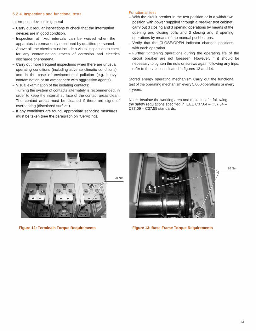
– Further tightening operations during the operating life of the
circuit breaker are not foreseen. However, if it should be
necessary to tighten the nuts or screws again following any trips,
refer to the values indicated in figures 13 and 14.
Stored energy operating mechanism Carry out the functional
test of the operating mechanism every 5,000 operations or every
4 years.
Note: Insulate the working area and make it safe, following the safety regulations specified in IEEE C37.04 – C37.54 – C37.09 – C37.55 standards.
20 Nm
20 Nm
Figure 12: Terminals Torque Requirements Figure 13: Base Frame Torque Requirements
24
5.2.5. Servicing
If cleaning is found to be necessary during the inspections, as
specified in par. “Operations before putting into service”, use
the following procedure:
- Insulate the working area and make it safe by following the
safety regulations specified in the ANSI/NFPA70/NEC
Standards.
- General cleaning of the surfaces:
- Dry and eliminate any light deposits of dirt using a soft dry
cloth;
- More resistant deposits of dirt can be removed using a slightly
alkaline household cleanser or Rivolta BWR 210 type
detergent.
- Cleaning the insulating surfaces and conductive components:
- Light dirt: with Rivolta BWR 210 detergent;
- Resistant dirt: with cold 716 type detergent.
After cleaning, rinse thoroughly with clean water and dry
carefully
Note: Only use halogen-free detergents and never trichloroethane, trichloroethylene or carbon tetrachloride!
5.2.6. Actuator and transmission system
A functional test of the drive must be carried out:
- when the number the number of operating cycles indicated
has been exceeded, (after 10,000 operation) or
- During maintenance operations.
Before carrying out the functional test, open the circuit breaker
and
- Take it to the test position - Discharge the closing or opening springs
- Visually inspect the lubrication conditions of the tulip isolating
contacts, of the sliding surfaces, etc.
- Check correct electrical and mechanical operation of the
various devices, with particular attention to the interlocks.
- The screws and nuts are tightened in the factory and correct
tightening is marked with a collared sign. No further tightening
operations are foreseen during the operating life of the circuit-
breaker.
Functional test:
- Connect the power supply voltage.
- Carry out several no-load operations. This test particularly
applies to circuit breakers which are rarely activated under
normal conditions.
Note: These operations can only be carried out by ABB personnel or suitably qualified and specially trained personnel.
25
5.2.7. Servicing details
- If provided, turn off the spring charging motor power supply
and manually discharge the operating mechanism springs by
closing and opening the circuit breaker.
- Replace parts subject to high climatic or mechanical stresses
(contact an ABB service center).
Note: These operations can only be carried out by ABB personnel or suitably qualified and specially trained personnel.
5.2.8. Vacuum interrupters
The vacuum interrupters are maintenance-free up to the
maximum number of electrical operations.
The operating life of the vacuum interrupter is defined by the sum
of the ultimate currents corresponding to the specific type of
interrupter: when the sum of the ultimate currents is reached, the
complete VI must be replaced, for electrical life, ask ABB.
Note: Dismantling and replacement of the interrupter assembly can only be carried out by ABB personnel or by qualified and specially trained personnel, especially for the necessary adjustments.
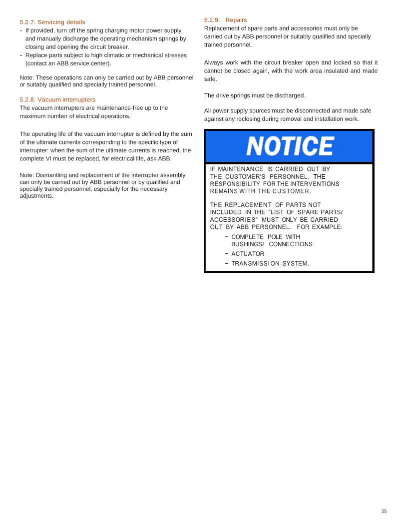
5.2.9. Repairs
Replacement of spare parts and accessories must only be
carried out by ABB personnel or suitably qualified and specially
trained personnel.
Always work with the circuit breaker open and locked so that it
cannot be closed again, with the work area insulated and made
safe.
The drive springs must be discharged.
All power supply sources must be disconnected and made safe
against any reclosing during removal and installation work.
26
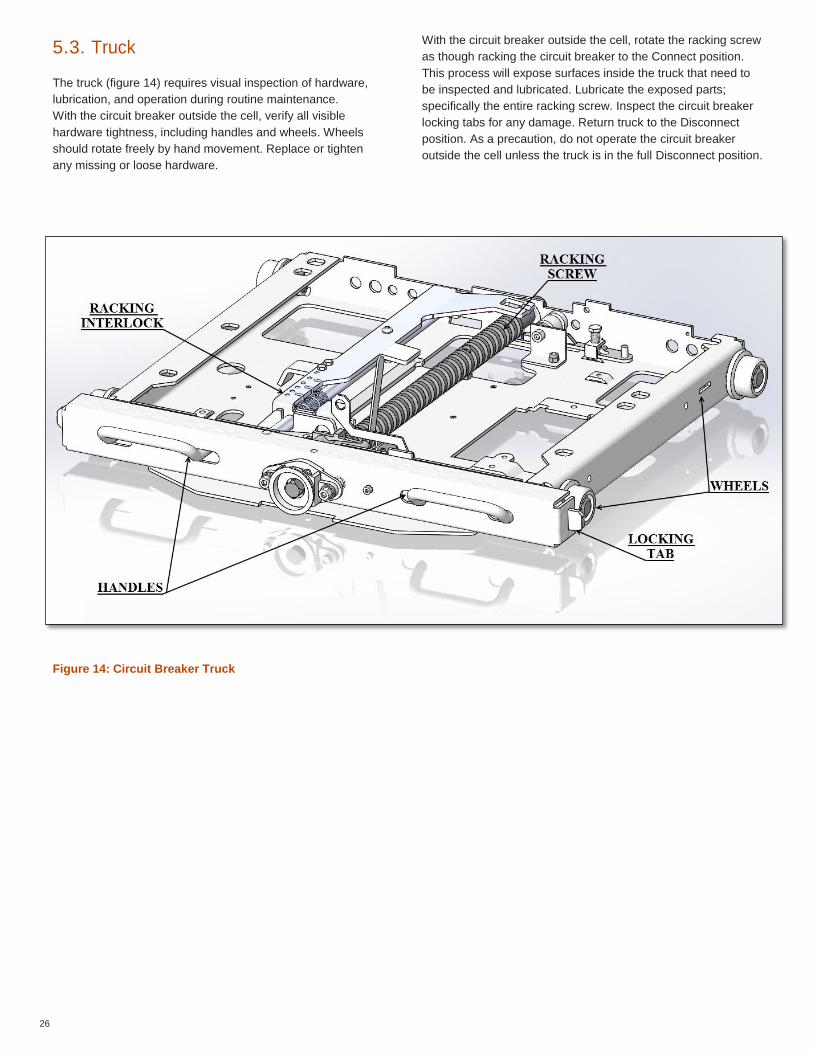
5.3. Truck
The truck (figure 14) requires visual inspection of hardware,
lubrication, and operation during routine maintenance.
With the circuit breaker outside the cell, verify all visible
hardware tightness, including handles and wheels. Wheels
should rotate freely by hand movement. Replace or tighten
any missing or loose hardware.
With the circuit breaker outside the cell, rotate the racking screw
as though racking the circuit breaker to the Connect position.
This process will expose surfaces inside the truck that need to
be inspected and lubricated. Lubricate the exposed parts;
specifically the entire racking screw. Inspect the circuit breaker
locking tabs for any damage. Return truck to the Disconnect
position. As a precaution, do not operate the circuit breaker
outside the cell unless the truck is in the full Disconnect position.
Figure 14: Circuit Breaker Truck
IMAGE TO CHANGE
27
DANCER
28
6. Spare parts and accessories
To order circuit breaker spare parts/accessories, refer to the ordering sales codes indicated in the technical catalogue and always state the following: – Type of circuit breaker – Rated voltage of the circuit breaker – Rated normal current of the circuit breaker – Breaking capacity of the circuit breaker – Serial number of the circuit breaker – Rated voltage of any electrical spare parts. For availability and to order spare parts, please contact our service office.
WARNING
6.1. List of spare parts
– Shunt opening release – Additional shunt opening release – Undervoltage release – Time delay device for undervoltage release – Mechanical override for undervoltage release – Shunt closing release – Spring charging geared motor with electrical signaling of springs
charged – Contact signaling geared motor protection circuit breaker
open/closed – Contact signaling closing springs charged/discharged – Circuit breaker auxiliary contacts – Locking electromagnet on the operating mechanism – Position contact of the withdrawable truck – Contacts signaling racked-in/isolated – Key lock in open position – Isolation interlock with the door – Protection for opening pushbutton – Protection for closing pushbutton – Locking electromagnet on the withdrawable truck – Set of six tulip contacts
29
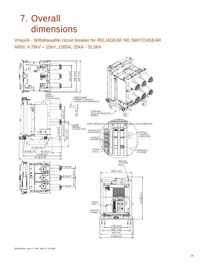
7. Overall dimensions
Vmax/A - Withdrawable circuit breaker for RELIAGEAR ND SWITCHGEAR
ANSI: 4.76kV – 15kV, 1200A, 25kA - 31.5kA
Dimensions are in “mm” and in “inches”.
30
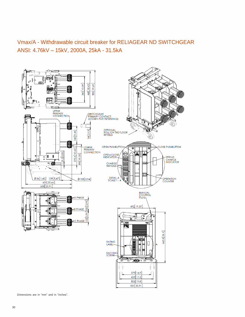
Vmax/A - Withdrawable circuit breaker for RELIAGEAR ND SWITCHGEAR
ANSI: 4.76kV – 15kV, 2000A, 25kA - 31.5kA
Dimensions are in “mm” and in “inches”.
31
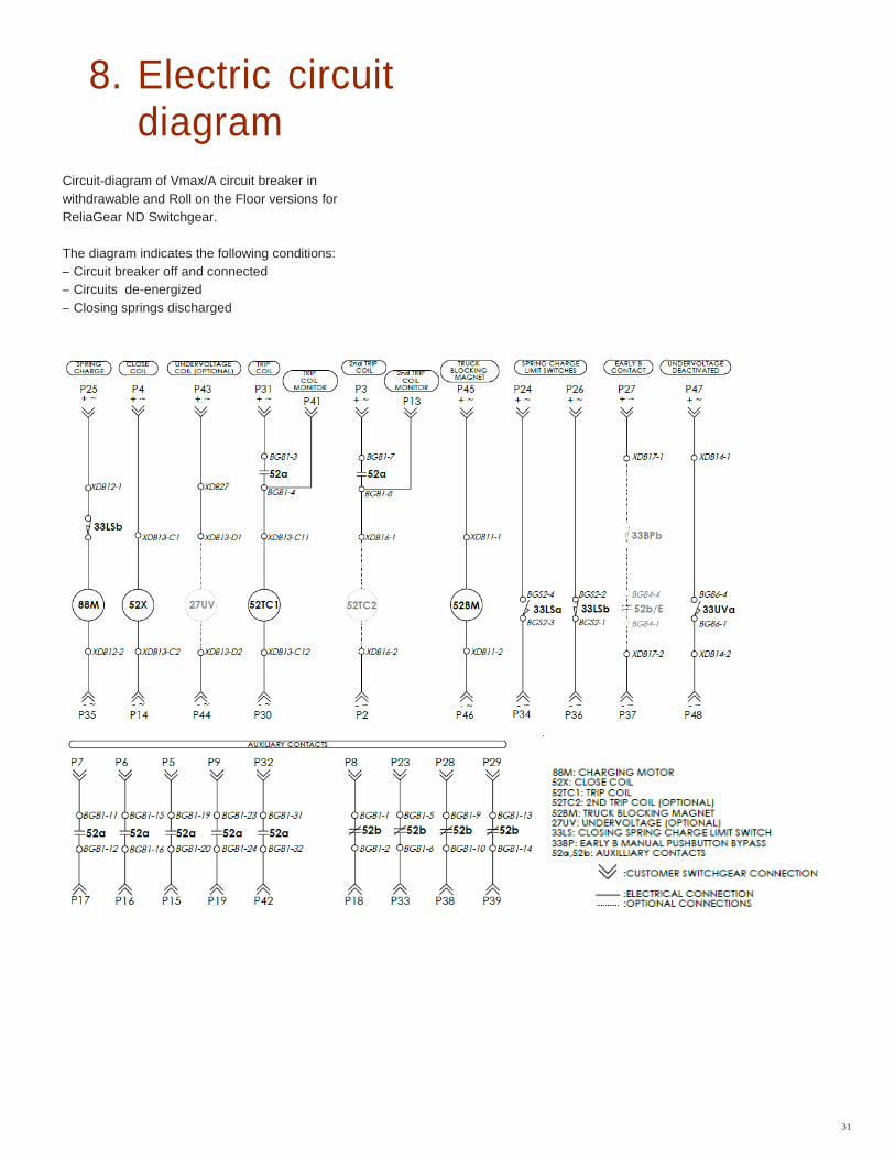
8. Electric circuit diagram
Circuit-diagram of Vmax/A circuit breaker in
withdrawable and Roll on the Floor versions for
ReliaGear ND Switchgear.
The diagram indicates the following conditions:
– Circuit breaker off and connected
– Circuits de-energized
– Closing springs discharged
32
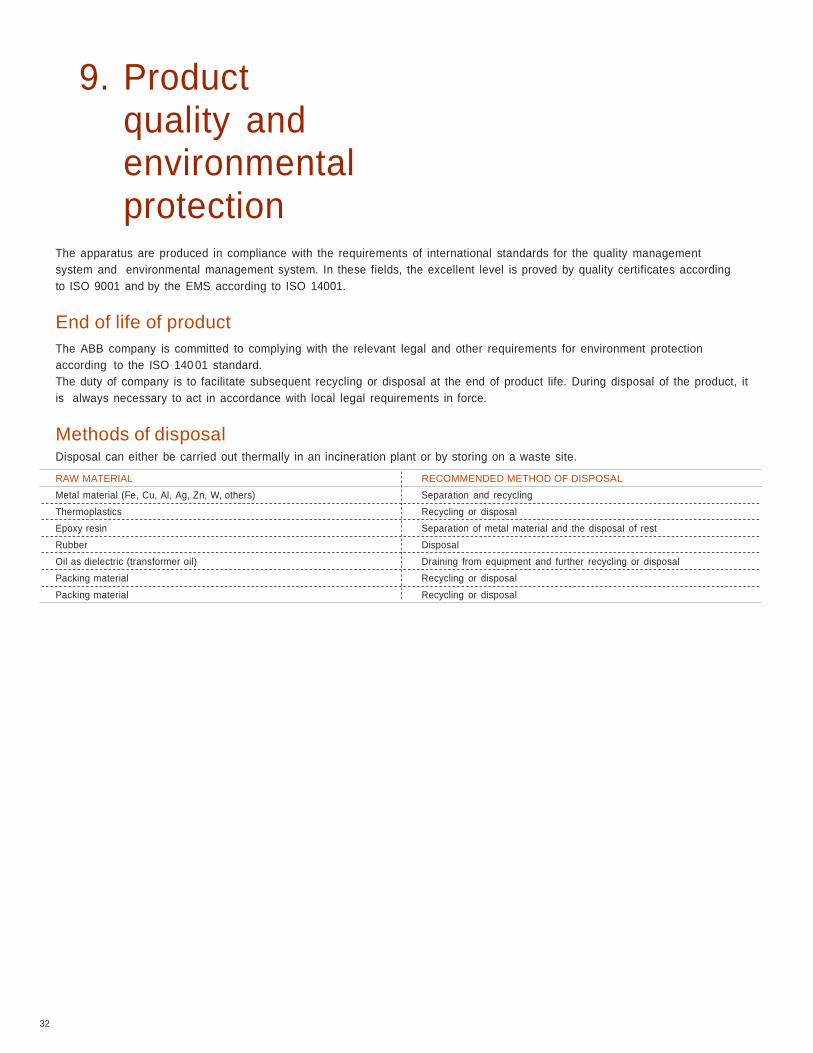
9. Product quality and environmental protection
The apparatus are produced in compliance with the requirements of international standards for the quality management
system and environmental management system. In these fields, the excellent level is proved by quality certificates according
to ISO 9001 and by the EMS according to ISO 14001.
End of life of product
The ABB company is committed to complying with the relevant legal and other requirements for environment protection
according to the ISO 140 01 standard.
The duty of company is to facilitate subsequent recycling or disposal at the end of product life. During disposal of the product, it
is always necessary to act in accordance with local legal requirements in force.
Methods of disposal Disposal can either be carried out thermally in an incineration plant or by storing on a waste site.
RAW MATERIAL RECOMMENDED METHOD OF DISPOSAL
Metal material (Fe, Cu, Al, Ag, Zn, W, others) Separation and recycling
Thermoplastics Recycling or disposal
Epoxy resin Separation of metal material and the disposal of rest
Rubber Disposal
Oil as dielectric (transformer oil) Draining from equipment and further recycling or disposal
Packing material Recycling or disposal
Packing material Recycling or disposal
ABB Inc. Medium Voltage Apparatus 655 Century Point Lake Mary, Florida 32746 Phone: +1 407 732 2000 Customer service: +1 800 929 7947 ext. 5
+1 407 732 2000 ext. 5 E-Mail: [email protected]
ABB Inc. Medium Voltage Service
2300 Mechanicsville Road Florence, South Carolina 29501 Phone: +1 800 HELP 365 (option 7)
+1 407 732 2000
www.abb.com/mediumvoltage www.abb.us/mvservice
The information contained in this document is for general information
purposes only. While ABB strives to keep the information up to date and
correct, it makes no representations or warranties of any kind, express or
implied, about the completeness, accuracy, reliability, suitability or
availability with respect to the information, products, services, or related
graphics contained in the document for any purpose. Any reliance placed
on such information is therefore strictly at your own risk. ABB reserves the
right to discontinue any product or service at any time.
© Copyright 2015 ABB. All rights reserved
1V
AL
05
76
01
-MB
– R
ev A
Ap
ril 2
015