Embed Size (px)
Citation preview
1
— PRODUC T INSTRUC TION
VD4Medium voltage vacuum circuit-breakerswith modular operating mechanism12 ... 24 kV, 630 ... 4000 A , 20 ... 40 kA

.
.
3
—
Contents
CO NTENTS
004 Description004 General006 Interrupting principle006 Versions available006 Fields of application007 Standards and approvals007 Service safety008 Accessories008 Operating mechanism009 Technical documentation009 Quality Assurance System009 Environmental Management System009 Health and Safety Management System010 Circuit-breaker selection and ordering010 General characteristics of fixed circuit-breakers016 General characteristics of withdrawable022 circuit-breakers022 Optional accessories028 Specific product characteristics028 Resistance to vibrations028 Tropicalization028 Altitude029 Anti-pumping device029 Environmental protection programe030 Overall dimensions030 Fixed circuit-breakers035 Withdrawable circuit-breakers041 Earthing device on truck042 Electrical circuit diagram042 Diagrams for fixed circuit breaker044 Diagrams for withdrawable circuit breaker046 Graphical symbols for electrical diagrams
VD4 MEDIUM VOLTAGE VACUUM CIRCUIT-BREAKERSWITH MODULAR OPERATING MECHANISM4
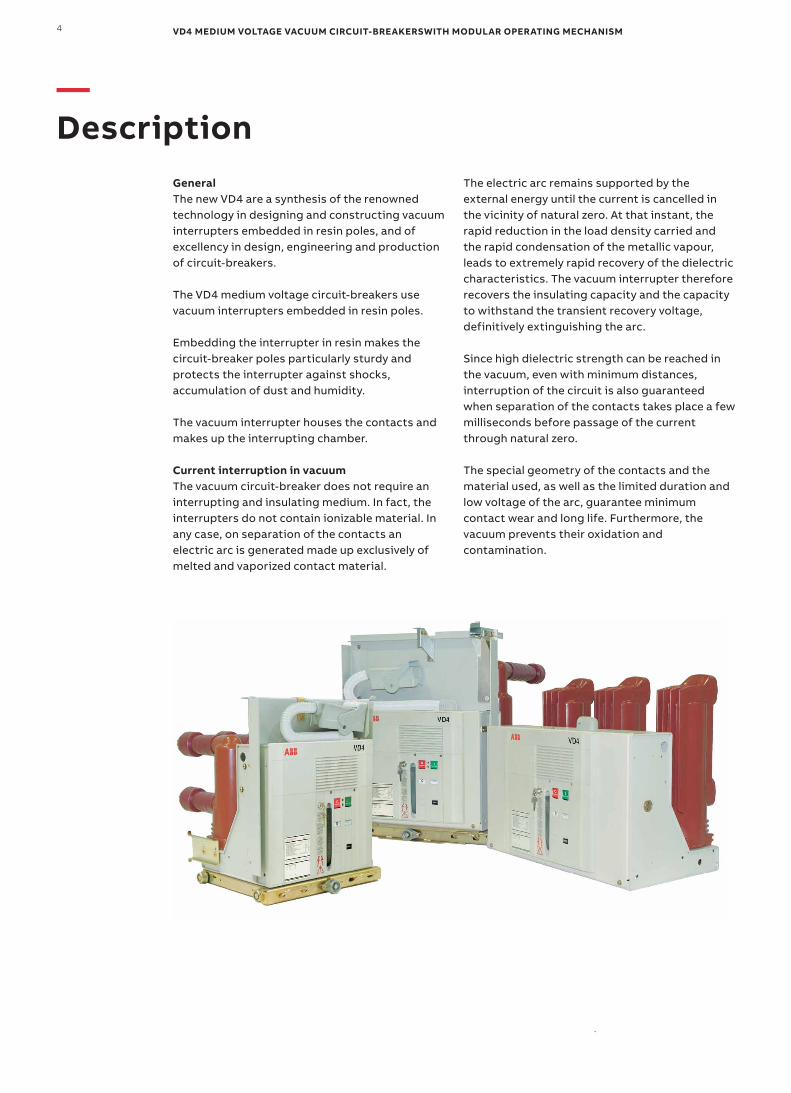
General The new VD4 are a synthesis of the renowned technology in designing and constructing vacuum interrupters embedded in resin poles, and of excellency in design, engineering and production of circuit-breakers.
The VD4 medium voltage circuit-breakers use vacuum interrupters embedded in resin poles. Embedding the interrupter in resin makes the circuit-breaker poles particularly sturdy and protects the interrupter against shocks, accumulation of dust and humidity.
The vacuum interrupter houses the contacts and makes up the interrupting chamber.
Current interruption in vacuum The vacuum circuit-breaker does not require an interrupting and insulating medium. In fact, the interrupters do not contain ionizable material. In any case, on separation of the contacts an electric arc is generated made up exclusively of melted and vaporized contact material.
The electric arc remains supported by the external energy until the current is cancelled in the vicinity of natural zero. At that instant, the rapid reduction in the load density carried and the rapid condensation of the metallic vapour, leads to extremely rapid recovery of the dielectric characteristics. The vacuum interrupter therefore recovers the insulating capacity and the capacity to withstand the transient recovery voltage, definitively extinguishing the arc.
Since high dielectric strength can be reached in the vacuum, even with minimum distances, interruption of the circuit is also guaranteed when separation of the contacts takes place a few milliseconds before passage of the current through natural zero.
The special geometry of the contacts and the material used, as well as the limited duration and low voltage of the arc, guarantee minimum contact wear and long life. Furthermore, the vacuum prevents their oxidation and contamination.
—Description
.
5D E SCR IP TI O N
EL type operating mechanismThe low speed of the contacts, together with the reduced run and low mass, limit the energy required for the operation and therefore guarantee extremely limited wear of the system. The circuit breaker therefore only requires limited maintenance.
The VD4 circuit-breakers use a mechanical operating mechanism, with stored energy and free trip. These characteristics allow opening and closing operations independent of the operator.
The operating mechanism is of simple conception and use and can be customised with a wide range of accessories which are easy and rapid to install. This simplicity converts into greater reliability of the apparatus.
The structureThe operating mechanism and the poles are fixed to a metal frame which is also the support for the fixed version of the circuit-breaker. The compact structure ensures sturdiness and mechanical reliability.
Apart from the isolating contacts and the cord with plug for connection of the auxiliary circuits, the withdrawable version is completed with the truck for racking it into and out of the switchgear or enclosure with the door closed.
• Vacuum interruption technique• Vacuum contacts protected against oxidation and contamination• Vacuum interrupter embedded in the resin poles• Interrupter protected against shocks, dust and humidity• Sealed-for-life poles• Operation under different climatic conditions• Limited switching energy• Stored energy operating mechanism with anti-pumping device
supplied as standard• Simple customisation with a complete range of accessories• Fixed and withdrawable version• Compact dimensions• Sturdiness and reliability• Limited maintenance• Circuit-breaker racking in and racking out with door closed• Incorrect and hazardous operations are prevented thanks to special
locks in the operating mechanism and in the truck• High environmental compatibility
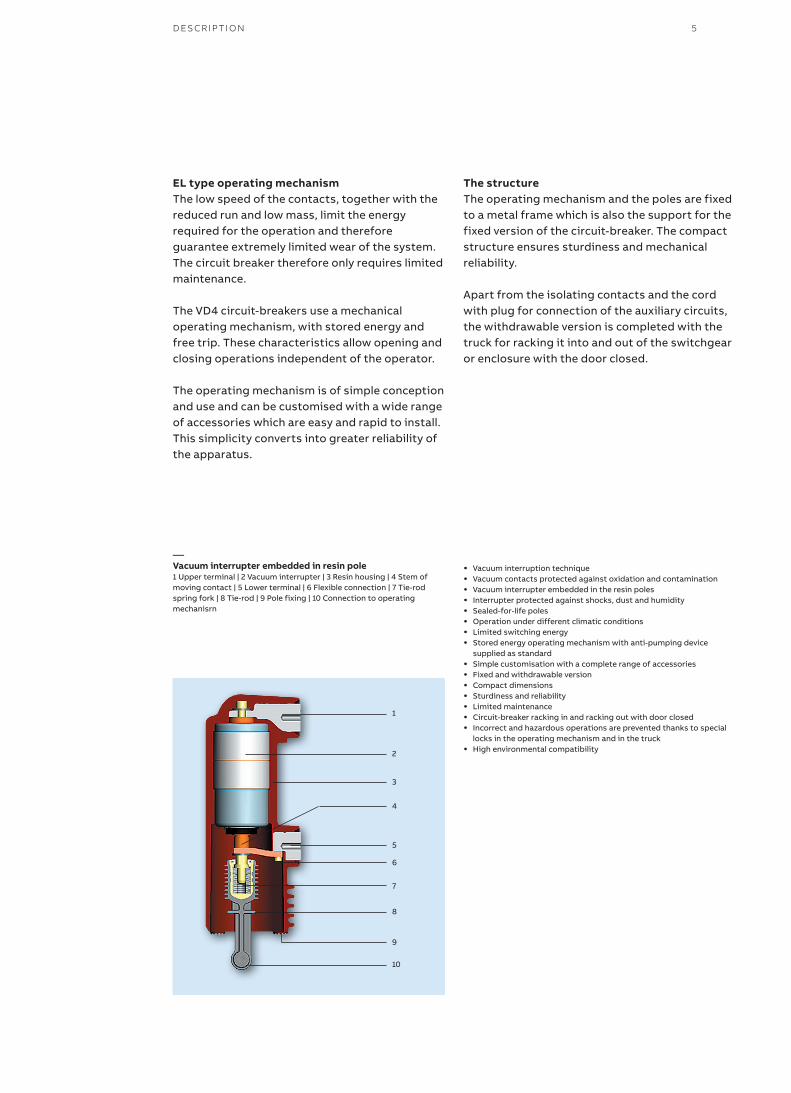
—Vacuum interrupter embedded in resin pole1 Upper terminal | 2 Vacuum interrupter | 3 Resin housing | 4 Stem of moving contact | 5 Lower terminal | 6 Flexible connection | 7 Tie-rod spring fork | 8 Tie-rod | 9 Pole fixing | 10 Connection to operating mechanisrn
1
2
3
4
6
5
7
8
9
10
VD4 MEDIUM VOLTAGE VACUUM CIRCUIT-BREAKERSWITH MODULAR OPERATING MECHANISM6
—Description
1
2
3
4
5
6
7
88
9
10
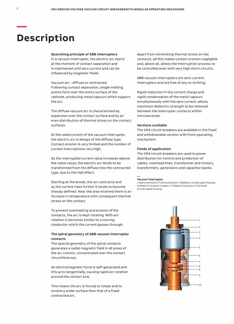
—Vacuum interrupter1 Stern/terminal | 2 Twist protection | 3 Bellows | 4 Interrupter housing5 Shield | 6 Ceramic insulator | 7 Shield | 8 Contacts | 9 Terminal10 Interrupter housing
Quenching principle of ABB interruptersIn a vacuum interrupter, the electric arc starts at the moment of contact separation and is maintained until zero current and can be influenced by magnetic fields.
Vacuum arc - diffuse or contractedFollowing contact separation, single melting points form over the entire surface of the cathode, producing metal vapours which support the arc.
The diffuse vacuum arc is characterised by expansion over the contact surface and by an even distribution of thermal stress on the contact surfaces.
At the rated current of the vacuum interrupter, the electric arc is always of the diffuse type. Contact erosion is very limited and the number of current interruptions very high.
As the interrupted current value increases (above the rated value), the electric arc tends to be transformed from the diffuse into the contracted type, due to the Hall effect.
Starting at the anode, the arc contracts and as the current rises further it tends to become sharply defined. Near the area involved there is an increase in temperature with consequent thermal stress on the contact.
To prevent overheating and erosion of the contacts, the arc is kept rotating. With arc rotation it becomes similar to a moving conductor which the current passes through.
The spiral geometry of ABB vacuum interrupter contactsThe special geometry of the spiral contacts generates a radial magnetic field in all areas of the arc column, concentrated over the contact circumferences.
An electromagnetic force is self-generated and this acts tangentially, causing rapid arc rotation around the contact axis.
This means the arc is forced to rotate and to involve a wider surface than that of a fixed contracted arc.
Apart from minimising thermal stress on the contacts, all this makes contact erosion negligible and, above all, allows the interruption process to be controlled even with very high short-circuits.
ABB vacuum interrupters are zero-current interrupters and are free of any re-striking.
Rapid reduction in the current charge and rapid condensation of the metal vapours simultaneously with the zero current, allows maximum dielectric strength to be restored between the interrupter contacts within microseconds.
Versions availableThe VD4 circuit-breakers are available in the fixed and withdrawable version with front operating mechanism.
Fields of applicationThe VD4 circuit-breakers are used in power distribution for control and protection of cables, overhead lines, transformer and motors, transformers, generators and capacitor banks.
7D E SCR IP TI O N
Standards and approvalsThe VD4 circuit-breakers comply with the GB/T 1984-2014, IEC 62271-100 Standards and with those of the major industrialised countries.
The VD4 circuit-breakers have undergone the tests indicated below and guarantee the safety and reliability of the apparatus in service in any installation.• Type tests: heating, withstand insulation at
power frequency, withstand insulation at lightning impulse, short-time and peak withstand current, mechanical life, short-circuit current making and breaking capacity, and no-load cable interruption.
• Individual tests: insulation of the main circuits with voltage at power frequency, auxiliary circuit and operating mechanism insulation, measurement of the main circuit resistance, mechanical and electrical operation.
Service safetyThanks to the complete range of mechanical and electrical locks (available on request), it is possible to construct safe distribution switchgear with the VD4 circuit-breakers.
The locking devices have been studied to prevent incorrect operations and to inspect the installations whilst guaranteeing maximum operator safety.
Key locks or padlock devices enable opening and closing operations and/or racking in and racking out.
The racking-out device with the door closed allows the circuit-breaker to be racked into or out of the switchgear only with the door closed.
Anti-racking-in locks prevent circuit-breakers with different rated currents from being racked in, and the racking-in operation with the circuit-breaker closed.
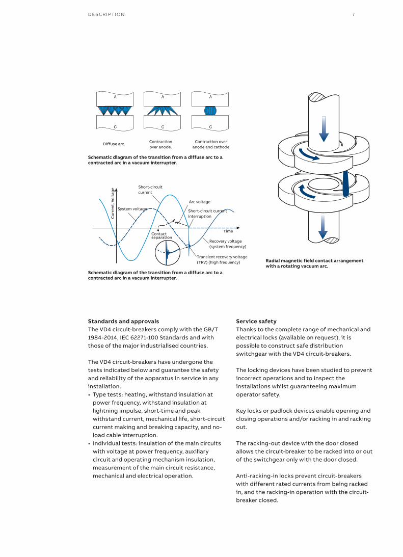
Radial magnetic field contact arrangement with a rotating vacuum arc.
Diffuse arc. Contraction over anode.
Contraction over anode and cathode.
Schematic diagram of the transition from a diffuse arc to a contracted arc in a vacuum interrupter.
Schematic diagram of the transition from a diffuse arc to a contracted arc in a vacuum interrupter.
Short-circuitcurrent
Short-circuit currentinterruption
Arc voltage
Recovery voltage(system frequency)
Transient recovery voltage(TRV) (high frequency)
TimeContactseparation
System voltage
Cur
rent
, Vo
ltag
e
VD4 MEDIUM VOLTAGE VACUUM CIRCUIT-BREAKERSWITH MODULAR OPERATING MECHANISM8
AccessoriesThe VD4 circuit-breakers have a complete range of accessories to satisfy all installation requirements.
The operating mechanism has a standardized range of accessories and spare parts which are easy to identify and order.
The accessories are installed conveniently from the front of the circuit-breaker. Electrical connection is carried out with plug-socket connectors.
Use, maintenance and service of the apparatus are simple and require limited use of resources.
Operating mechanismThe operating mechanism of VD4 circuit-breakers is of simple conception and use, and can be customised with a wide range of accessories which are easy and rapid to install. This simplicity converts into greater reliability of the apparatus.
The operating mechanism is of the stored energy type, has the anti-pumping device mounted as standard and is fitted with suitable locks to prevent incorrect operations.
Each operation sequence is only enabled if all the conditions ensuring it being carried out correctly are respected.
The accessories are the same for all types of VD4 circuit-breakers.
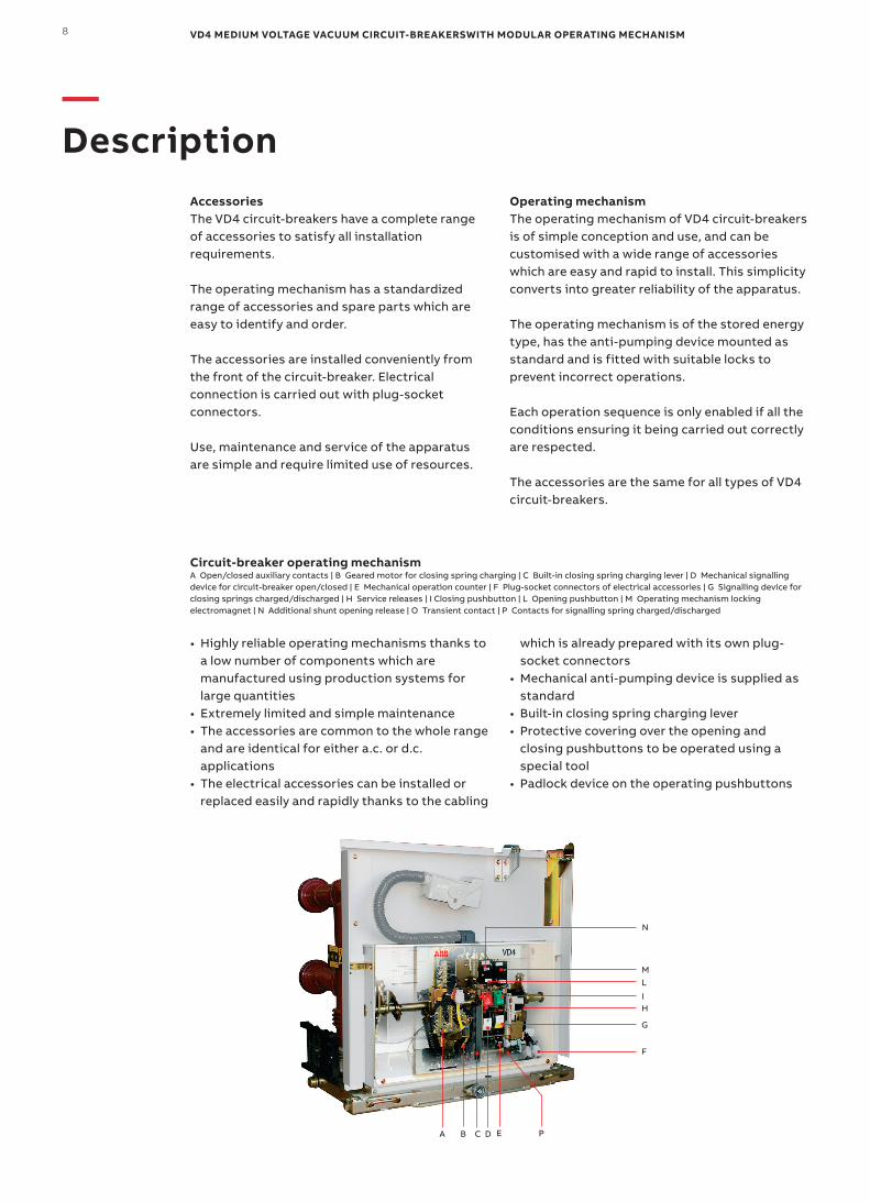
Circuit-breaker operating mechanismA Open/closed auxiliary contacts | B Geared motor for closing spring charging | C Built-in closing spring charging lever | D Mechanical signalling device for circuit-breaker open/closed | E Mechanical operation counter | F Plug-socket connectors of electrical accessories | G Signalling device for closing springs charged/discharged | H Service releases | I Closing pushbutton | L Opening pushbutton | M Operating mechanism locking electromagnet | N Additional shunt opening release | O Transient contact | P Contacts for signalling spring charged/discharged
• Highly reliable operating mechanisms thanks to a low number of components which are manufactured using production systems for large quantities
• Extremely limited and simple maintenance• The accessories are common to the whole range
and are identical for either a.c. or d.c. applications
• The electrical accessories can be installed or replaced easily and rapidly thanks to the cabling
which is already prepared with its own plug-socket connectors
• Mechanical anti-pumping device is supplied as standard
• Built-in closing spring charging lever• Protective covering over the opening and
closing pushbuttons to be operated using a special tool
• Padlock device on the operating pushbuttons
—Description
N
ML
IH
G
F
PEDCBA
9
Technical documentationTo go into technical and application aspects of the VD4 circuit-breakers in depth, ask for the following publications:
UniGear ZS1 type switchgear Code: 1YHA000015
REF542 plus Code: 1YZA000003
Quality systemComplies with ISO 9001:2008 Standards, certified by an independent organisation.
Environmental management systemComplies with ISO 14001:2004 Standards, certified by an independent organisation.
Health and safety management systemComplies with OHSAS 18001:2007 Standards, certified by an independent organisation.
D E SCR IP TI O N
VD4 MEDIUM VOLTAGE VACUUM CIRCUIT-BREAKERSWITH MODULAR OPERATING MECHANISM10
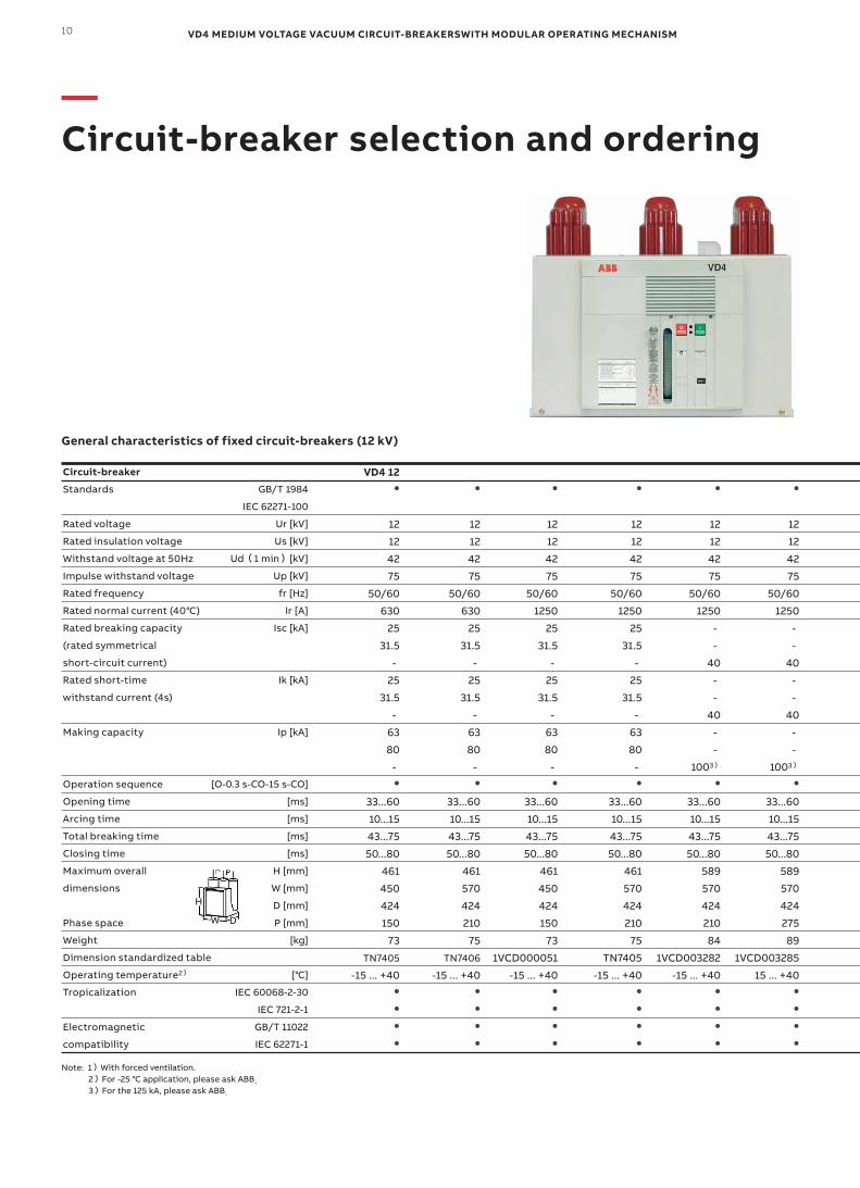
General characteristics of fixed circuit-breakers (12 kV)
—Circuit-breaker selection and ordering
GB/T 1984
IEC 62271-100
Ur [kV]
Us [kV]
Ud(1 min)[kV]
Up [kV]
fr [Hz]
Ir [A]
Isc [kA]
Ik [kA]
Ip [kA]
[O-0.3 s-CO-15 s-CO]
[ms]
[ms]
[ms]
[ms]
H [mm]
W [mm]
D [mm]
P [mm]
[kg]
[℃]
IEC 60068-2-30
IEC 721-2-1
GB/T 11022
IEC 62271-1
Note: 1)With forced ventilation. 2)For -25 ℃ application, please ask ABB. 3)For the 125 kA, please ask ABB.
Circuit-breaker
Standards
Rated voltage
Rated insulation voltage
Withstand voltage at 50Hz
Impulse withstand voltage
Rated frequency
Rated normal current (40℃)
Rated breaking capacity
(rated symmetrical
short-circuit current)
Rated short-time
withstand current (4s)
Making capacity
Operation sequence
Opening time
Arcing time
Total breaking time
Closing time
Maximum overall
dimensions
Phase space
Weight
Dimension standardized table
Operating temperature2)
Tropicalization
Electromagnetic
compatibility
VD4 12●
12
12
42
75
50/60
630
25
31.5
-
25
31.5
-
63
80
-●
33...60
10...15
43...75
50...80
461
450
424
150
73
TN7405
-15 ... +40●
●
●
●
●
12
12
42
75
50/60
630
25
31.5
-
25
31.5
-
63
80
-●
33...60
10...15
43...75
50...80
461
570
424
210
75
TN7406
-15 ... +40●
●
●
●
●
12
12
42
75
50/60
1250
25
31.5
-
25
31.5
-
63
80
-●
33...60
10...15
43...75
50...80
461
450
424
150
73
1VCD000051
-15 ... +40●
●
●
●
●
12
12
42
75
50/60
1250
25
31.5
-
25
31.5
-
63
80
-●
33...60
10...15
43...75
50...80
461
570
424
210
75
TN7405
-15 ... +40●
●
●
●
●
12
12
42
75
50/60
1250
-
-
40
-
-
40
-
-
1003)
●
33...60
10...15
43...75
50...80
589
570
424
210
84
1VCD003282
-15 ... +40●
●
●
●
●
12
12
42
75
50/60
1250
-
-
40
-
-
40
-
-
1003)
●
33...60
10...15
43...75
50...80
589
570
424
275
89
1VCD003285
15 ... +40●
●
●
●
H
W D
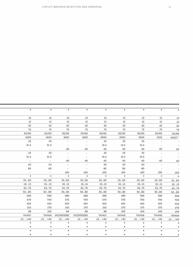
11CI R C U IT- B R E A K ER SEL EC TI O N A N D O R D ER I N G
●
12
12
42
75
50/60
1600
25
31.5
-
25
31.5
-
63
80
-●
33...60
10...15
43...75
50...80
599
570
424
210
98
TN7407
-15 ... +40●
●
●
●
●
12
12
42
75
50/60
1600
25
31.5
-
25
31.5
-
63
80
-●
33...60
10...15
43...75
50...80
599
700
424
275
105
TN7408
-15 ... +40●
●
●
●
●
12
12
42
75
50/60
1600
-
-
40
-
-
40
-
-
100●
33...60
10...15
43...75
50...80
589
570
424
210
84
1VCD003282
-15 ... +40●
●
●
●
●
12
12
42
75
50/60
1600
-
-
40
-
-
40
-
-
100●
33...60
10...15
43...75
50...80
589
700
424
275
89
1VCD003285
-15 ... +40●
●
●
●
●
12
12
42
75
50/60
2000
25
31.5
40
25
31.5
40
63
80
100●
33...60
10...15
43...75
50...80
599
570
424
210
98
TN7407
-15 ... +40●
●
●
●
●
12
12
42
75
50/60
2000
25
31.5
40
25
31.5
40
63
80
100●
33...60
10...15
43...75
50...80
599
700
424
275
105
TN7408
-15 ... +40●
●
●
●
●
12
12
42
75
50/60
2500
25
31.5
40
25
31.5
40
63
80
100●
33...60
10...15
43...75
50...80
599
700
424
275
105
TN7408
-15 ... +40●
●
●
●
●
12
12
42
75
50/60
3150
-
-
40
-
-
40
-
-
100●
33...60
10...15
43...75
50...80
599
700
424
275
140
TN7408
-15 ... +40●
●
●
●
●
12
12
42
75
50/60
40001)
-
-
40
-
-
40
-
-
100●
33...60
10...15
43...75
50...80
599
700
424
275
140
TN7408
-15 ... +40●
●
●
●

VD4 MEDIUM VOLTAGE VACUUM CIRCUIT-BREAKERSWITH MODULAR OPERATING MECHANISM12
IEC 62271-100
Ur [kV]
Us [kV]
Ud(1 min)[kV]
Up [kV]
fr [Hz]
Ir [A]
Isc [kA]
Ik [kA]
Ip [kA]
[O-0.3 s-CO-15 s-CO]
[ms]
[ms]
[ms]
[ms]
H [mm]
W [mm]
D [mm]
P [mm]
[kg]
[℃]
IEC 60068-2-30
IEC 721-2-1
GB/T 11022
IEC 62271-1
Note: 1)With forced ventilation. 2)For -25℃ application, please ask ABB. 3)For the 125 kA, please ask ABB.
VD4 17●
17.5
17.5
38
95
50/60
630
25
31.5
-
25
31.5
-
63
80
-●
33...60
10...15
43...75
50...80
461
450
424
150
73
TN7405
-15 ... +40●
●
●
●
●
17.5
17.5
38
95
50/60
630
25
31.5
-
25
31.5
-
63
80
-●
33...60
10...15
43...75
50...80
461
570
424
210
75
TN7406
-15 ... +40●
●
●
●
●
17.5
17.5
38
95
50/60
1250
25
31.5
-
25
31.5
-
63
80
-●
33...60
10...15
43...75
50...80
461
450
424
150
73
1VCD000051
-15 ... +40●
●
●
●
●
17.5
17.5
38
95
50/60
1250
25
31.5
-
25
31.5
-
63
80
-●
33...60
10...15
43...75
50...80
461
570
424
210
75
TN7405
-15 ... +40●
●
●
●
●
117.5
17.5
38
95
50/60
1250
-
-
40
-
-
40
-
-
100●
33...60
10...15
43...75
50...80
589
570
424
210
84
1VCD003282
-15 ... +40●
●
●
●
●
17.5
17.5
38
95
50/60
1250
-
-
40
-
-
40
-
-
100●
33...60
10...15
43...75
50...80
589
570
424
275
89
1VCD003285
15 ... +40●
●
●
●
H
W D
General characteristics of fixed circuit-breakers (17.5 kV)
—Circuit-breaker selection and ordering
Circuit-breaker
Standards
Rated voltage
Rated insulation voltage
Withstand voltage at 50Hz
Impulse withstand voltage
Rated frequency
Rated normal current (40℃)
Rated breaking capacity
(rated symmetrical
short-circuit current)
Rated short-time
withstand current (4s)
Making capacity
Operation sequence
Opening time
Arcing time
Total breaking time
Closing time
Maximum overall
dimensions
Phase space
Weight
Dimension standardized table
Operating temperature2)
Tropicalization
Electromagnetic
compatibility

13
●
17.5
17.5
38
95
50/60
1600
25
31.5
-
25
31.5
-
63
80
-●
33...60
10...15
43...75
50...80
599
570
424
210
98
TN7407
-15 ... +40●
●
●
●
●
17.5
17.5
38
95
50/60
1600
25
31.5
-
25
31.5
-
63
80
-●
33...60
10...15
43...75
50...80
599
700
424
275
105
TN7408
-15 ... +40●
●
●
●
●
17.5
17.5
38
95
50/60
1600
-
-
40
-
-
40
-
-
100●
33...60
10...15
43...75
50...80
589
570
424
210
84
1VCD003282
-15 ... +40●
●
●
●
●
17.5
17.5
38
95
50/60
1600
-
-
40
-
-
40
-
-
100●
33...60
10...15
43...75
50...80
589
700
424
275
89
1VCD003285
-15 ... +40●
●
●
●
●
17.5
17.5
38
95
50/60
2000
25
31.5
40
25
31.5
40
63
80
100●
33...60
10...15
43...75
50...80
599
570
424
210
98
TN7407
-15 ... +40●
●
●
●
●
17.5
17.5
38
95
50/60
2000
25
31.5
40
25
31.5
40
63
80
100●
33...60
10...15
43...75
50...80
599
700
424
275
105
TN7408
-15 ... +40●
●
●
●
●
17.5
17.5
38
95
50/60
2500
25
31.5
40
25
31.5
40
63
80
100●
33...60
10...15
43...75
50...80
599
700
424
275
105
TN7408
-15 ... +40●
●
●
●
●
17.5
17.5
38
95
50/60
3150
-
-
40
-
-
40
-
-
100●
33...60
10...15
43...75
50...80
599
700
424
275
140
TN7408
-15 ... +40●
●
●
●
●
17.5
17.5
38
95
50/60
40001)
-
-
40
-
-
40
-
-
100●
33...60
10...15
43...75
50...80
599
700
424
275
140
TN7408
-15 ... +40●
●
●
●
CI R C U IT- B R E A K ER SEL EC TI O N A N D O R D ER I N G
VD4 MEDIUM VOLTAGE VACUUM CIRCUIT-BREAKERSWITH MODULAR OPERATING MECHANISM14
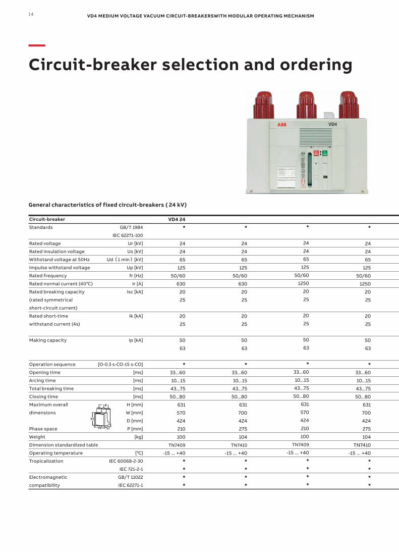
General characteristics of fixed circuit-breakers ( 24 kV)
—Circuit-breaker selection and ordering
GB/T 1984
IEC 62271-100
Ur [kV]
Us [kV]
Ud(1 min)[kV]
Up [kV]
fr [Hz]
Ir [A]
Isc [kA]
Ik [kA]
Ip [kA]
[O-0.3 s-CO-15 s-CO]
[ms]
[ms]
[ms]
[ms]
H [mm]
W [mm]
D [mm]
P [mm]
[kg]
[℃]
IEC 60068-2-30
IEC 721-2-1
GB/T 11022
IEC 62271-1
VD4 24●
24
24
65
125
50/60
630
20
25
20
25
50
63
●
33...60
10...15
43...75
50...80
631
570
424
210
100
TN7409
-15 ... +40●
●
●
●
●
24
24
65
125
50/60
630
20
25
20
25
50
63
●
33...60
10...15
43...75
50...80
631
700
424
275
104
TN7410
-15 ... +40●
●
●
●
●
24
24
65
125
50/60
1250
20
25
20
25
50
63
●
33...60
10...15
43...75
50...80
631
570
424
210
100
TN7409
-15 ... +40●
●
●
●
●
24
24
65
125
50/60
1250
20
25
20
25
50
63
●
33...60
10...15
43...75
50...80
631
700
424
275
104
TN7410
-15 ... +40●
●
●
●
H
W D
Circuit-breaker
Standards
Rated voltage
Rated insulation voltage
Withstand voltage at 50Hz
Impulse withstand voltage
Rated frequency
Rated normal current (40℃)
Rated breaking capacity
(rated symmetrical
short-circuit current)
Rated short-time
withstand current (4s)
Making capacity
Operation sequence
Opening time
Arcing time
Total breaking time
Closing time
Maximum overall
dimensions
Phase space
Weight
Dimension standardized table
Operating temperature
Tropicalization
Electromagnetic
compatibility
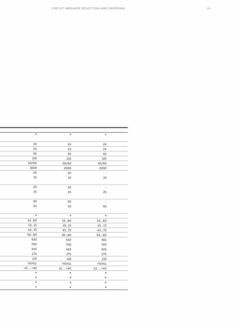
15CI R C U IT- B R E A K ER SEL EC TI O N A N D O R D ER I N G
●
24
24
65
125
50/60
1600
20
25
20
25
50
63
●
33...60
10...15
43...75
50...80
642
700
424
275
110
TN7411
-15 ... +40●
●
●
●
●
24
24
65
125
50/60
2000
20
25
20
25
50
63
●
33...60
10...15
43...75
50...80
642
700
424
275
110
TN7411
15 ... +40●
●
●
●
●
24
24
65
125
50/60
2000
-
25
-
25
-
63
●
33...60
10...15
43...75
50...80
661
700
424
275
110
TN7411
-15 ... +40●
●
●
●
VD4 MEDIUM VOLTAGE VACUUM CIRCUIT-BREAKERSWITH MODULAR OPERATING MECHANISM16
GB/T 1984
IEC 62271-100
Ur [kV]
Us [kV]
Ud(1 min)[kV]
Up [kV]
fr [Hz]
Ir [A]
Isc [kA]
Ik [kA]
Ip [kA]
[O-0.3 s-CO-15 s-CO]
[ms]
[ms]
[ms]
[ms]
H [mm]
W [mm]
D [mm]
P [mm]
[kg]
[℃]
IEC 60068-2-30
IEC 721-2-1
GB/T 11022
IEC 62271-1
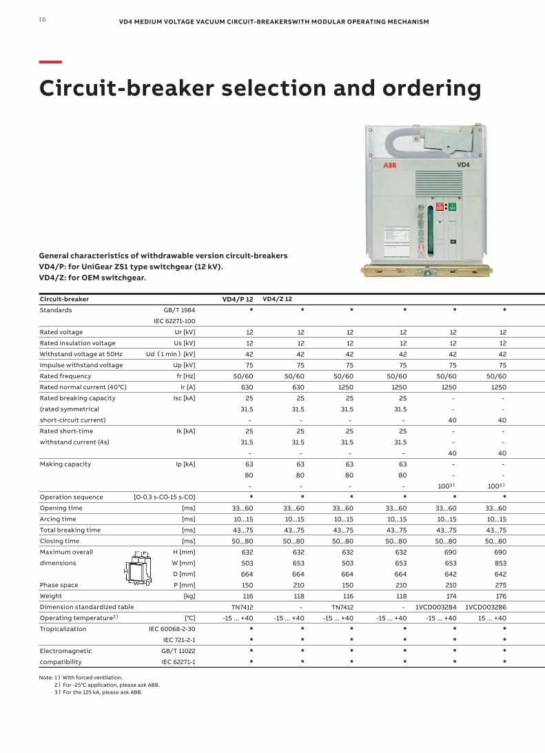
General characteristics of withdrawable version circuit-breakersVD4/P: for UniGear ZS1 type switchgear (12 kV).VD4/Z: for OEM switchgear.
Note: 1)With forced ventilation. 2)For -25℃ application, please ask ABB. 3)For the 125 kA, please ask ABB.
VD4/P 12 ●
12
12
42
75
50/60
630
25
31.5
-
25
31.5
-
63
80
-●
33...60
10...15
43...75
50...80
632
503
664
150
116
TN7412
-15 ... +40●
●
●
●
●
12
12
42
75
50/60
630
25
31.5
-
25
31.5
-
63
80
-●
33...60
10...15
43...75
50...80
632
653
664
210
118
-
-15 ... +40●
●
●
●
●
12
12
42
75
50/60
1250
25
31.5
-
25
31.5
-
63
80
-●
33...60
10...15
43...75
50...80
632
503
664
150
116
TN7412
-15 ... +40●
●
●
●
●
12
12
42
75
50/60
1250
25
31.5
-
25
31.5
-
63
80
-●
33...60
10...15
43...75
50...80
632
653
664
210
118
-
-15 ... +40●
●
●
●
●
12
12
42
75
50/60
1250
-
-
40
-
-
40
-
-
1003)
●
33...60
10...15
43...75
50...80
690
653
642
210
174
1VCD003284
-15 ... +40●
●
●
●
●
12
12
42
75
50/60
1250
-
-
40
-
-
40
-
-
1003)
●
33...60
10...15
43...75
50...80
690
853
642
275
176
1VCD003286
15 ... +40●
●
●
●
VD4/Z 12
H
W D
—Circuit-breaker selection and ordering
Circuit-breaker
Standards
Rated voltage
Rated insulation voltage
Withstand voltage at 50Hz
Impulse withstand voltage
Rated frequency
Rated normal current (40℃)
Rated breaking capacity
(rated symmetrical
short-circuit current)
Rated short-time
withstand current (4s)
Making capacity
Operation sequence
Opening time
Arcing time
Total breaking time
Closing time
Maximum overall
dimensions
Phase space
Weight
Dimension standardized table
Operating temperature2)
Tropicalization
Electromagnetic
compatibility

17
●
12
12
42
75
50/60
1600
25
31.5
-
25
31.5
-
63
80
-●
33...60
10...15
43...75
50...80
690
653
642
210
160
TN7415
-15 ... +40●
●
●
●
●
12
12
42
75
50/60
1600
25
31.5
-
25
31.5
-
63
80
-●
33...60
10...15
43...75
50...80
690
853
642
275
166
TN7416
-15 ... +40●
●
●
●
●
12
12
42
75
50/60
1600
-
-
40
-
-
40
-
-
100●
33...60
10...15
43...75
50...80
690
653
642
210
174
1VCD003284
-15 ... +40●
●
●
●
●
12
12
42
75
50/60
1600
-
-
40
-
-
40
-
-
100●
33...60
10...15
43...75
50...80
690
853
642
275
176
1VCD003286
-15 ... +40●
●
●
●
●
12
12
42
75
50/60
2000
25
31.5
40
25
31.5
40
63
80
100●
33...60
10...15
43...75
50...80
690
653
642
210
160
TN7415
-15 ... +40●
●
●
●
●
12
12
42
75
50/60
2000
25
31.5
40
25
31.5
40
63
80
100●
33...60
10...15
43...75
50...80
690
853
642
275
166
TN7416
-15 ... +40●
●
●
●
●
12
12
42
75
50/60
2500
25
31.5
40
25
31.5
40
63
80
100●
33...60
10...15
43...75
50...80
690
853
642
275
186
TN7417
-15 ... +40●
●
●
●
●
12
12
42
75
50/60
3150
-
-
40
-
-
40
-
-
100●
33...60
10...15
43...75
50...80
690
853
642
275
216
TN7417
-15 ... +40●
●
●
●
●
12
12
42
75
50/60
40001)
-
-
40
-
-
40
-
-
100●
33...60
10...15
43...75
50...80
690
853
642
275
216
TN7417
-15 ... +40●
●
●
●
CI R C U IT- B R E A K ER SEL EC TI O N A N D O R D ER I N G
VD4 MEDIUM VOLTAGE VACUUM CIRCUIT-BREAKERSWITH MODULAR OPERATING MECHANISM18
—Circuit-breaker selection and ordering
IEC 62271-100
Ur [kV]
Us [kV]
Ud(1 min)[kV]
Up [kV]
fr [Hz]
Ir [A]
Isc [kA]
Ik [kA]
Ip [kA]
[O-0.3 s-CO-15 s-CO]
[ms]
[ms]
[ms]
[ms]
H [mm]
W [mm]
D [mm]
P [mm]
[kg]
[℃]
IEC 60068-2-30
IEC 721-2-1
GB/T 11022
IEC 62271-1
Note: 1)With forced ventilation. 2)For -25℃ application, please ask ABB.
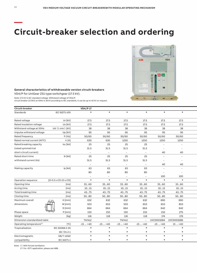
VD4/P 17●
17.5
17.5
38
95
50/60
630
25
31.5
-
25
31.5
-
63
80
-●
33...60
10...15
43...75
50...80
632
503
664
150
116
TN7412
-15 ... +40●
●
●
●
●
17.5
17.5
38
95
50/60
630
25
31.5
-
25
31.5
-
63
80
-●
33...60
10...15
43...75
50...80
632
653
664
210
118
-
-15 ... +40●
●
●
●
●
17.5
17.5
38
95
50/60
1250
25
31.5
-
25
31.5
-
63
80
-●
33...60
10...15
43...75
50...80
632
503
664
150
116
TN7412
-15 ... +40●
●
●
●
●
17.5
17.5
38
95
50/60
1250
25
31.5
-
25
31.5
-
63
80
-●
33...60
10...15
43...75
50...80
632
653
664
210
118
-
-15 ... +40●
●
●
●
●
17.5
17.5
38
95
50/60
1250
-
-
40
-
-
40
-
-
100●
33...60
10...15
43...75
50...80
690
653
642
210
174
1VCD003284
-15 ... +40●
●
●
●
●
17.5
17.5
38
95
50/60
1250
-
-
40
-
-
40
-
-
100●
33...60
10...15
43...75
50...80
690
853
642
275
176
1VCD003286
15 ... +40●
●
●
●
General characteristics of withdrawable version circuit-breakersVD4/P for UniGear ZS1 type switchgear (17.5 kV).Note: 17.5 kV is IEC standard voltage. Withstand voltage of VD4/P.circuit breaker (17.5kV) at 50Hz is 38 kV according to IEC standards, it can be up to 42 kV on request.
H
W D
Circuit-breaker
Standards
Rated voltage
Rated insulation voltage
Withstand voltage at 50Hz
Impulse withstand voltage
Rated frequency
Rated normal current (40℃)
Rated breaking capacity
(rated symmetrical
short-circuit current)
Rated short-time
withstand current (4s)
Making capacity
Operation sequence
Opening time
Arcing time
Total breaking time
Closing time
Maximum overall
dimensions
Phase space
Weight
Dimension standardized table
Operating temperature2)
Tropicalization
Electromagnetic
compatibility

19CI R C U IT- B R E A K ER SEL EC TI O N A N D O R D ER I N G
●
17.5
17.5
38
95
50/60
1600
25
31.5
-
25
31.5
-
63
80
-●
33...60
10...15
43...75
50...80
690
653
642
210
160
TN7415
-15 ... +40●
●
●
●
●
17.5
17.5
38
95
50/60
1600
25
31.5
-
25
31.5
-
63
80
-●
33...60
10...15
43...75
50...80
690
853
642
275
166
TN7416
-15 ... +40●
●
●
●
●
17.5
17.5
38
95
50/60
1600
-
-
40
-
-
40
-
-
100●
33...60
10...15
43...75
50...80
690
653
642
210
174
1VCD003284
-15 ... +40●
●
●
●
●
17.5
17.5
38
95
50/60
1600
-
-
40
-
-
40
-
-
100●
33...60
10...15
43...75
50...80
690
853
642
275
176
1VCD003286
-15 ... +40●
●
●
●
●
17.5
17.5
38
95
50/60
2000
25
31.5
40
25
31.5
40
63
80
100●
33...60
10...15
43...75
50...80
690
653
642
210
160
TN7415
-15 ... +40●
●
●
●
●
17.5
17.5
38
95
50/60
2000
25
31.5
40
25
31.5
40
63
80
100●
33...60
10...15
43...75
50...80
690
853
642
275
166
TN7416
-15 ... +40●
●
●
●
●
17.5
17.5
38
95
50/60
2500
25
31.5
40
25
31.5
40
63
80
100●
33...60
10...15
43...75
50...80
690
853
642
275
186
TN7417
-15 ... +40●
●
●
●
●
17.5
17.5
38
95
50/60
3150
-
-
40
-
-
40
-
-
100●
33...60
10...15
43...75
50...80
690
853
642
275
216
TN7417
-15 ... +40●
●
●
●
●
17.5
17.5
38
95
50/60
40001)
-
-
40
-
-
40
-
-
100●
33...60
10...15
43...75
50...80
690
853
642
275
216
TN7417
-15 ... +40●
●
●
●
VD4 MEDIUM VOLTAGE VACUUM CIRCUIT-BREAKERSWITH MODULAR OPERATING MECHANISM20
—Circuit-breaker selection and ordering
GB/T 1984
IEC 62271-100
Ur [kV]
Us [kV]
Ud(1 min)[kV]
Up [kV]
fr [Hz]
Ir [A]
Isc [kA]
Ik [kA]
Ip [kA]
[O-0.3 s-CO-15 s-CO]
[ms]
[ms]
[ms]
[ms]
H [mm]
W [mm]
D [mm]
P [mm]
[kg]
[℃]
IEC 60068-2-30
IEC 721-2-1
GB/T 11022
IEC 62271-1
VD4/P 24●
24
24
65
125
50/60
630
20
25
20
25
50
63
●
33...60
10...15
43...75
50...80
794
653
802
210
140
TN7413
-15 ... +40●
●
●
●
●
24
24
65
125
50/60
630
20
25
20
25
50
63
●
33...60
10...15
43...75
50...80
794
853
802
275
148
TN7414
-15 ... +40●
●
●
●
●
24
24
65
125
50/60
1250
20
25
20
25
50
63
●
33...60
10...15
43...75
50...80
794
653
802
210
140
TN7413
-15 ... +40●
●
●
●
●
24
24
65
125
50/60
1250
20
25
20
25
50
63
●
33...60
10...15
43...75
50...80
794
853
802
275
148
TN7414
-15 ... +40●
●
●
●
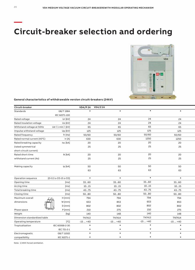
General characteristics of withdrawable version circuit-breakers (24kV)
VD4/Z 24
Note: 1) With forced ventilation.
H
W D
Circuit-breaker
Standards
Rated voltage
Rated insulation voltage
Withstand voltage at 50Hz
Impulse withstand voltage
Rated frequency
Rated normal current (40℃)
Rated breaking capacity
(rated symmetrical
short-circuit current)
Rated short-time
withstand current (4s)
Making capacity
Operation sequence
Opening time
Arcing time
Total breaking time
Closing time
Maximum overall
dimensions
Phase space
Weight
Dimension standardized table
Operating temperature
Tropicalization
Electromagnetic
compatibility
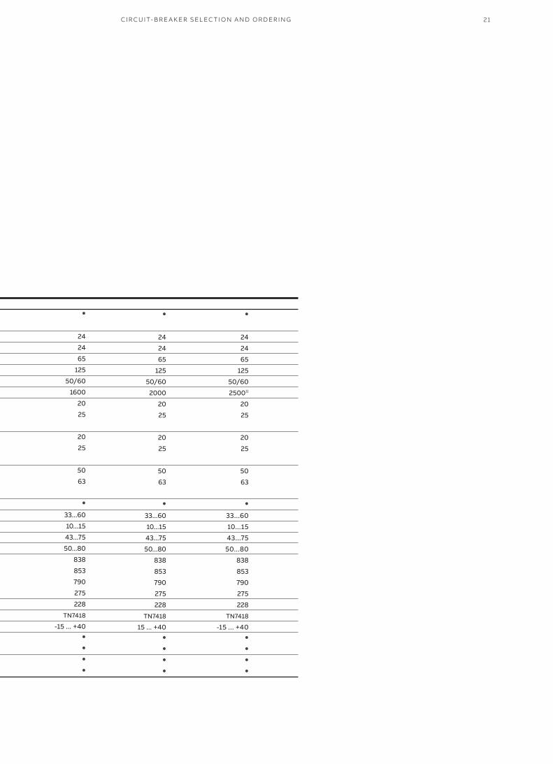
21CI R C U IT- B R E A K ER SEL EC TI O N A N D O R D ER I N G
●
24
24
65
125
50/60
1600
20
25
20
25
50
63
●
33...60
10...15
43...75
50...80
838
853
790
275
228
TN7418
-15 ... +40●
●
●
●
●
24
24
65
125
50/60
2000
20
25
20
25
50
63
●
33...60
10...15
43...75
50...80
838
853
790
275
228
TN7418
15 ... +40●
●
●
●
●
24
24
65
125
50/60
25001)
20
25
20
25
50
63
●
33...60
10...15
43...75
50...80
838
853
790
275
228
TN7418
-15 ... +40●
●
●
●
VD4 MEDIUM VOLTAGE VACUUM CIRCUIT-BREAKERSWITH MODULAR OPERATING MECHANISM22
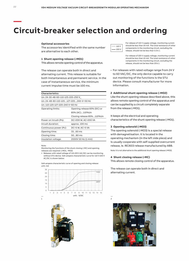
0
5
10
15
20
25
30
1 2 3 4 5 6 7 8 9 10 11 12 13 14 15
110 V
220 V
unit:V/DC—1
—2
110 V
220 V
For release of 110 V supply voltage, monitoring current should be less than 20 mA. The total resistance of other components in the monitoring circuit, excluding the release, should not be less than 5.5 .
For release of 220 V supply voltage, monitoring current should be less than 10 mA. The total resistance of other components in the monitoring circuit, excluding the release, should not be less than 20 .
• For releases with rated voltage range from 24 V to 60 VAC/DC, the only device capable to carry out monitoring of the functions is the STU device. Please consult manufacturer for more information.
2 Additional shunt opening release (-MO2)Like the shunt opening release described above, this allows remote opening control of the apparatus and can be supplied by a circuit completely separate from the release (-MO1).
It keeps all the electrical and operating characteristics of the shunt opening release (-MO1).
3 Opening solenoid (-MO3)The opening solenoid (-MO3) is a special release with demagnetisation. It is located in the operating mechanism (in the left side piece) and is usually cooperate with self-supplied overcurrent release, ie. REJ603 release manufactured by ABB.
Note: it is not alternative to the additional shunt opening release (-MO2).
4 Shunt closing release (-MC)This allows remote closing control of the apparatus.
The release can operate both in direct and alternating current.
—Circuit-breaker selection and ordering
Optional accessoriesThe accessories identified with the same number are alternative to each other.
1 Shunt opening release (-MO1)This allows remote opening control of the apparatus.
The release can operate both in direct and alternating current. This release is suitable for both instantaneous and permanent service. In the case of instantaneous service, the minimum current impulse time must be 100 ms.
Characteristics
Un: 24-30-48-60-110-125-220-250 V_
Un: 24-48-60-110-120...127-220...240-V~50 Hz
Un: 110-120-127-220-240 V~60 Hz
Operating limits: Opening release 65% (DC) or
85% (AC)...110%Un
Closing release 85%...110%Un
Power on inrush (Ps): DC=200 W; AC=200 VA
Inrush duration: approx. 100 ms
Continuous power (Pc): DC=5 W; AC=5 VA
Opening time: 33...60 ms
Closing time: 50...80 ms
Insulation voltage: 2000V 50 Hz (1 min)
Note: Monitoring the functions of the shunt closing (-MC) and opening releases are required: (-MO1, -MO2) • Releases with rated voltage of 110-220 V AC/DC can be monitoring
without STU device. Volt-ampere characteristic curve for 110 V-220 V AC/DC is shown below:
Volt-ampere characteristic curve of opening and closing releaseunit: mA
23
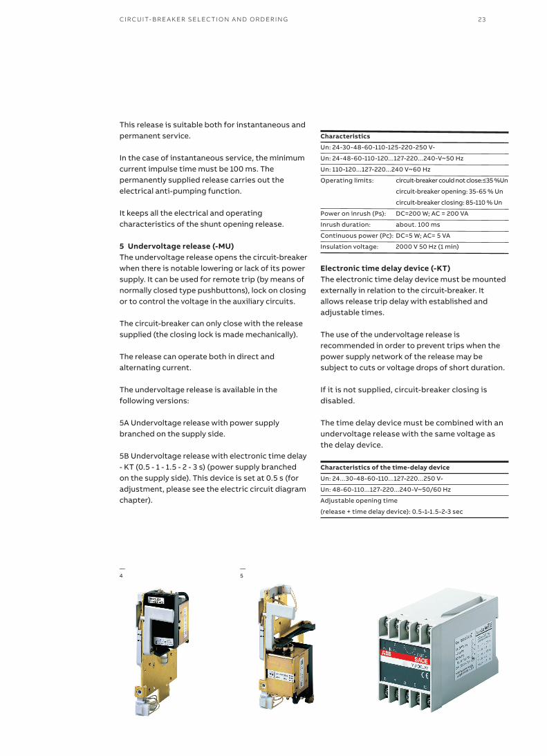
—4
—5
This release is suitable both for instantaneous and permanent service.
In the case of instantaneous service, the minimum current impulse time must be 100 ms. The permanently supplied release carries out the electrical anti-pumping function.
It keeps all the electrical and operating characteristics of the shunt opening release.
5 Undervoltage release (-MU)The undervoltage release opens the circuit-breaker when there is notable lowering or lack of its power supply. It can be used for remote trip (by means of normally closed type pushbuttons), lock on closing or to control the voltage in the auxiliary circuits.
The circuit-breaker can only close with the release supplied (the closing lock is made mechanically).
The release can operate both in direct and alternating current.
The undervoltage release is available in the following versions:
5A Undervoltage release with power supply branched on the supply side.
5B Undervoltage release with electronic time delay - KT (0.5 - 1 - 1.5 - 2 - 3 s) (power supply branched on the supply side). This device is set at 0.5 s (for adjustment, please see the electric circuit diagram chapter).
Characteristics
Un: 24-30-48-60-110-125-220-250 V-
Un: 24-48-60-110-120...127-220...240-V~50 Hz
Un: 110-120...127-220...240 V~60 Hz
Operatinglimits: circuit-breakercouldnotclose:≤35%Un
circuit-breaker opening: 35-65 % Un
circuit-breaker closing: 85-110 % Un
Power on inrush (Ps): DC=200 W; AC = 200 VA
Inrush duration: about. 100 ms
Continuous power (Pc): DC=5 W; AC= 5 VA
Insulation voltage: 2000 V 50 Hz (1 min)
Electronic time delay device (-KT)The electronic time delay device must be mounted externally in relation to the circuit-breaker. It allows release trip delay with established and adjustable times.
The use of the undervoltage release is recommended in order to prevent trips when the power supply network of the release may be subject to cuts or voltage drops of short duration.
If it is not supplied, circuit-breaker closing is disabled.
The time delay device must be combined with an undervoltage release with the same voltage as the delay device.
Characteristics of the time-delay device
Un: 24...30-48-60-110...127-220...250 V-
Un: 48-60-110...127-220...240-V~50/60 Hz
Adjustable opening time
(release + time delay device): 0.5-1-1.5-2-3 sec
CI R C U IT- B R E A K ER SEL EC TI O N A N D O R D ER I N G
VD4 MEDIUM VOLTAGE VACUUM CIRCUIT-BREAKERSWITH MODULAR OPERATING MECHANISM24
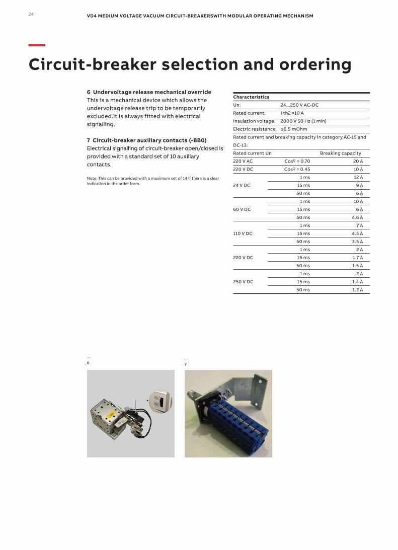
6 Undervoltage release mechanical overrideThis is a mechanical device which allows the undervoltage release trip to be temporarily excluded.It is always fitted with electrical signalling.
7 Circuit-breaker auxiliary contacts (-BB0)Electrical signalling of circuit-breaker open/closed is provided with a standard set of 10 auxiliary contacts.
Note: This can be provided with a maximum set of 14 if there is a clear indication in the order form.
—6
—7
—Circuit-breaker selection and ordering
Characteristics
Un: 24...250 V AC-DC
Rated current: I th2 =10 A
Insulation voltage: 2000 V 50 Hz (1 min)
Electricresistance: ≤6.5mOhm
Rated current and breaking capacity in category AC-15 and
DC-13:
Rated current Un Breaking capacity
220 V AC Cos = 0.70 20 A
220 V DC Cos = 0.45 10 A
1 ms 12 A
24 V DC 15 ms 9 A
50 ms 6 A
1 ms 10 A
60 V DC 15 ms 6 A
50 ms 4.6 A
1 ms 7 A
110 V DC 15 ms 4.5 A
50 ms 3.5 A
1 ms 2 A
220 V DC 15 ms 1.7 A
50 ms 1.5 A
1 ms 2 A
250 V DC 15 ms 1.4 A
50 ms 1.2 A
25
—10
—11
—12
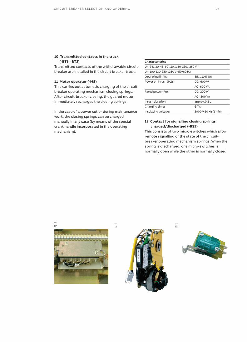
10 Transmitted contacts in the truck (-BT1; -BT2)Transmitted contacts of the withdrawable circuit-breaker are installed in the circuit breaker truck.
11 Motor operator (-MS)This carries out automatic charging of the circuit-breaker operating mechanism closing springs. After circuit-breaker closing, the geared motor immediately recharges the closing springs.
In the case of a power cut or during maintenance work, the closing springs can be charged manually in any case (by means of the special crank handle incorporated in the operating mechanism).
Characteristics
Un: 24...30-48-60-110...130-220...250 V-
Un: 100-130-220...250 V~50/60 Hz
Operating limits: 85...110% Un
Power on inrush (Ps): DC=600 W
AC=600 VA
Rated power (Pn): DC=200 W
AC =200 VA
Inrush duration: approx.0.2 s
Charging time: 6-7 s
Insulating voltage: 2000 V 50 Hz (1 min)
12 Contact for signalling closing springs charged/discharged (-BS2)This consists of two micro-switches which allow remote signalling of the state of the circuit-breaker operating mechanism springs. When the spring is discharged, one micro-switches is normally open while the other is normally closed.
CI R C U IT- B R E A K ER SEL EC TI O N A N D O R D ER I N G
VD4 MEDIUM VOLTAGE VACUUM CIRCUIT-BREAKERSWITH MODULAR OPERATING MECHANISM26
—13
—14
—15
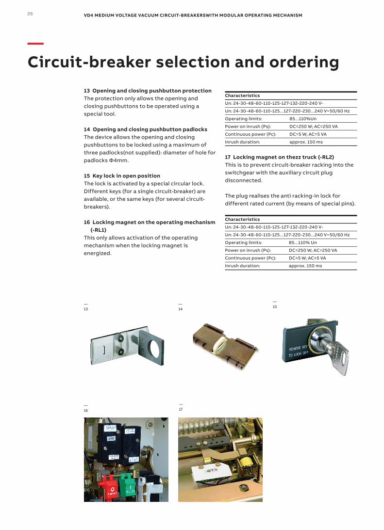
13 Opening and closing pushbutton protectionThe protection only allows the opening and closing pushbuttons to be operated using a special tool.
14 Opening and closing pushbutton padlocksThe device allows the opening and closing pushbuttons to be locked using a maximum of three padlocks(not supplied): diameter of hole for padlocks Φ4mm.
15 Key lock in open positionThe lock is activated by a special circular lock. Different keys (for a single circuit-breaker) are available, or the same keys (for several circuit-breakers).
16 Locking magnet on the operating mechanism (-RL1)This only allows activation of the operating mechanism when the locking magnet is energized.
Characteristics
Un: 24-30-48-60-110-125-127-132-220-240 V-
Un: 24-30-48-60-110-125...127-220-230...240 V~50/60 Hz
Operating limits: 85...110%Un
Power on inrush (Ps): DC=250 W; AC=250 VA
Continuous power (Pc): DC=5 W; AC=5 VA
Inrush duration: approx. 150 ms
17 Locking magnet on thezz truck (-RL2)This is to prevent circuit-breaker racking into the switchgear with the auxiliary circuit plug disconnected.
The plug realises the anti racking-in lock for different rated current (by means of special pins).
Characteristics
Un: 24-30-48-60-110-125-127-132-220-240 V-
Un: 24-30-48-60-110-125...127-220-230...240 V~50/60 Hz
Operating limits: 85...110% Un
Power on inrush (Ps): DC=250 W; AC=250 VA
Continuous power (Pc): DC=5 W; AC=5 VA
Inrush duration: approx. 150 ms
—16
—17
—Circuit-breaker selection and ordering
27CI R C U IT- B R E A K ER SEL EC TI O N A N D O R D ER I N G
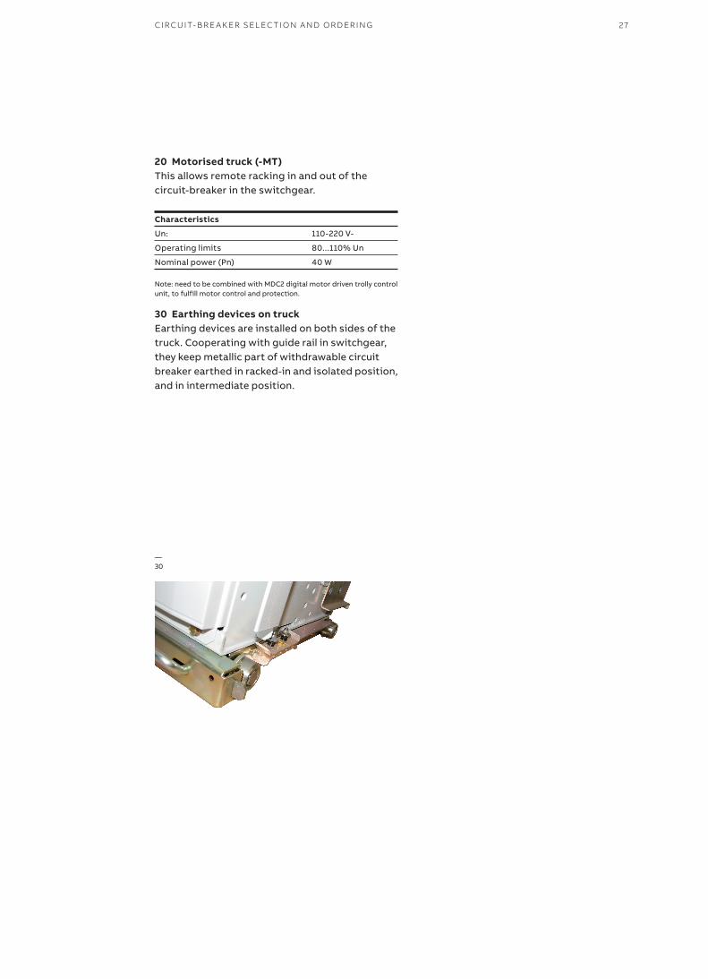
20 Motorised truck (-MT)This allows remote racking in and out of the circuit-breaker in the switchgear.
Characteristics
Un: 110-220 V-
Operating limits 80...110% Un
Nominal power (Pn) 40 W
Note: need to be combined with MDC2 digital motor driven trolly control unit, to fulfill motor control and protection.
30 Earthing devices on truckEarthing devices are installed on both sides of the truck. Cooperating with guide rail in switchgear, they keep metallic part of withdrawable circuit breaker earthed in racked-in and isolated position, and in intermediate position.
—30

VD4 MEDIUM VOLTAGE VACUUM CIRCUIT-BREAKERSWITH MODULAR OPERATING MECHANISM28
Resistance to vibrationsVD4 circuit-breakers are unaffected by mechanically generated vibrations.
For the versions approved by the naval registers, please contact us.
TropicalizationVD4 circuit-breakers are manufactured in compliance with the strictest regulations regarding use in hot-humid-saline climates.
All the most important metal components are treated against corrosive factors according to UNI 3564-65 Standards environmental class C.
Galvanisation is carried out in accordance with UNI ISO 2081 Standards, classification code Fe/Zn 12, with a thickness of 12x10-6 m, protected by a conversion layer mainly consisting of chromates in compliance with the UNI ISO 4520 Standard.
These construction characteristics mean that the whole VD4 series of circuit-breakers and its accessories comply with standards as follows:IEC 60721-2-1 (climate graph 8 )IEC 60068-2-2 (Test B: Dry Heat ) IEC 60068-2-30 (Test Bd: Damp Heat, cyclic)
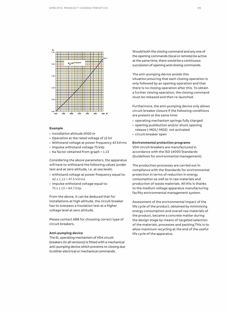
AltitudeThe insulating property of air decreases as the altitude increases, therefore this must always be taken into account for external insulation of the apparatus (the internal insulation of the interrupters does not undergo any variations as it is guaranteed by the vacuum). The phenomenon must always be taken into consideration during the design stage of the insulating components of apparatus to be installed over 1000 m above sea level.
In this case a correction coefficient must be considered, which can be taken from the graph on the next page, built up on the basis of the indications in the IEC 60694 Standards.
The following example is a clear interpretation of the indications given above.
Graph for determining the Ka correction factor according to the altitudeH = altitude in metres;m = value referred to power frequency and the lightning impulse withstand voltages and those between phase and phase.
—Specific product characteristics
29SPECIFI C PR O D U C T CH A R AC TER IS TI C S
Example
• Installation altitude 2000 m• Operation at the rated voltage of 12 kV• Withstand voltage at power frequency 42 kVrms• Impulse withstand voltage 75 kVp• Ka factor obtained from graph = 1.13
Considering the above parameters, the apparatus will have to withstand the following values (under test and at zero altitude, i.e. at sea level):
• withstand voltage at power frequency equal to: 42 x 1.13 = 47.5 kVrms• impulse withstand voltage equal to: 75 x 1.13 = 84.7 kVp
From the above, it can be deduced that for installations at high altitude, the circuit breaker has to overpass a insulation test at a higher voltage level at zero altitude.
Please contact ABB for choosing correct type of circuit breakers.
Anti-pumping deviceThe EL operating mechanism of VD4 circuit-breakers (in all versions) is fitted with a mechanical anti-pumping device which prevents re-closing due to either electrical or mechanical commands.
Should both the closing command and any one of the opening commands (local or remote) be active at the same time, there would be a continuous succession of opening and closing commands.
The anti-pumping device avoids this situation,ensuring that each closing operation is only followed by an opening operation and that there is no closing operation after this. To obtain a further closing operation, the closing command must be released and then re-launched.
Furthermore, the anti-pumping device only allows circuit-breaker closure if the following conditions are present at the same time:
• operating mechanism springs fully charged• opening pushbutton and/or shunt opening
release (-MO1/-MO2) not activated• circuit-breaker open
Environmental protection programeVD4 circuit-breakers are manufactured in accordance with the ISO 14000 Standards (Guidelines for environmental management).
The production processes are carried out in compliance with the Standards for environmental protection in terms of reduction in energy consumption as well as in raw materials and production of waste materials. All this is thanks to the medium voltage apparatus manufacturing facility environmental management system.
Assessment of the environmental impact of the life cycle of the product, obtained by minimising energy consumption and overall raw materials of the product, became a concrete matter during the design stage by means of targeted selection of the materials, processes and packing.This is to allow maximum recycling at the end of the useful life cycle of the apparatus.
VD4 MEDIUM VOLTAGE VACUUM CIRCUIT-BREAKERSWITH MODULAR OPERATING MECHANISM30
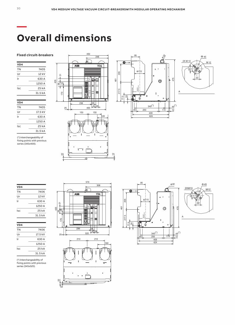
—Overall dimensions
VD4
TN 7405
Ur 12 kV
lr 630 A
1250 A
lsc 25 kA
31.5 kA
VD4
TN 7405
Ur 17.5 kV
lr 630 A
1250 A
lsc 25 kA
31.5 kA
(*) Interchangeability of fixing points with previous series (345x400).
VD4
TN 7406
Ur 12 kV
lr 630 A
1250 A
lsc 25 kA
31.5 kA
VD4
TN 7406
Ur 17.5 kV
lr 630 A
1250 A
lsc 25 kA
31.5 kA
(*) Interchangeability of fixing points with previous series (345x520).
A
A
Fixed circuit-breakers
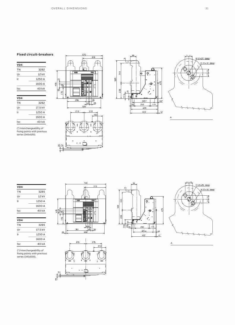
31OV ER A L L D I M ENSI O NS
VD4
TN 3282
Ur 12 kV
lr 1250 A
1600 A
lsc 40 kA
VD4
TN 3282
Ur 17.5 kV
lr 1250 A
1600 A
lsc 40 kA
(*) Interchangeability of fixing points with previous series (345x520).
VD4
TN 3285
Ur 12 kV
lr 1250 A
1600 A
lsc 40 kA
VD4
TN 3285
Ur 17.5 kV
lr 1250 A
1600 A
lsc 40 kA
(*) Interchangeability of fixing points with previous series (345x650).
A
A
Fixed circuit-breakers
VD4 MEDIUM VOLTAGE VACUUM CIRCUIT-BREAKERSWITH MODULAR OPERATING MECHANISM32
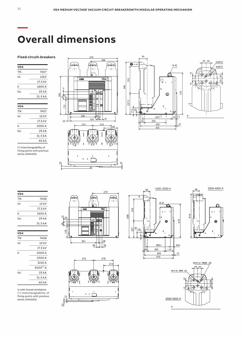
—Overall dimensions
VD4
TN 7408
Ur 12 kV
17.5 kV
lr 1600 A
lsc 25 kA
31.5 kA
VD4
TN 7408
Ur 12 kV
17.5 kV
lr 2000 A
2500 A
3150 A
40001)A
lsc 25 kA
31.5 kA
40 kA
1) with forced ventilation.(*) Interchangeability of fixing points with previous series (345x650).
VD4
TN 7407
Ur 12kV
17.5 kV
lr 1600 A
lsc 25 kA
31.5 kA
VD4
TN 7407
Ur 12 kV
17.5 kV
lr 2000 A
lsc 25 kA
31.5 kA
40 kA
(*) Interchangeability of fixing points with previous series (345x520).
A
A
Fixed circuit-breakers
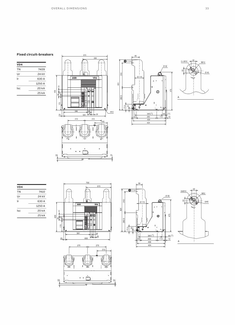
33OV ER A L L D I M ENSI O NS
VD4
TN 7409
Ur 24 kV
lr 630 A
1250 A
lsc 20 kA
25 kA
VD4
TN 7410
Ur 24 kV
lr 630 A
1250 A
lsc 20 kA
25 kA
A
A
Fixed circuit-breakers
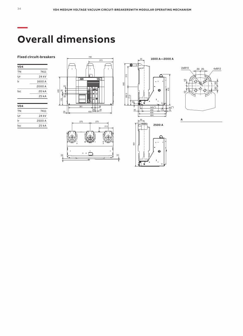
VD4 MEDIUM VOLTAGE VACUUM CIRCUIT-BREAKERSWITH MODULAR OPERATING MECHANISM34
—Overall dimensions
VD4
TN 7411
Ur 24 kV
lr 1600 A
2000 A
lsc 20 kA
25 kA
VD4
TN 7411
Ur 24 kV
lr 2500 A
lsc 25 kA
A
1600 A—2000 A
2500 A
Fixed circuit-breakers
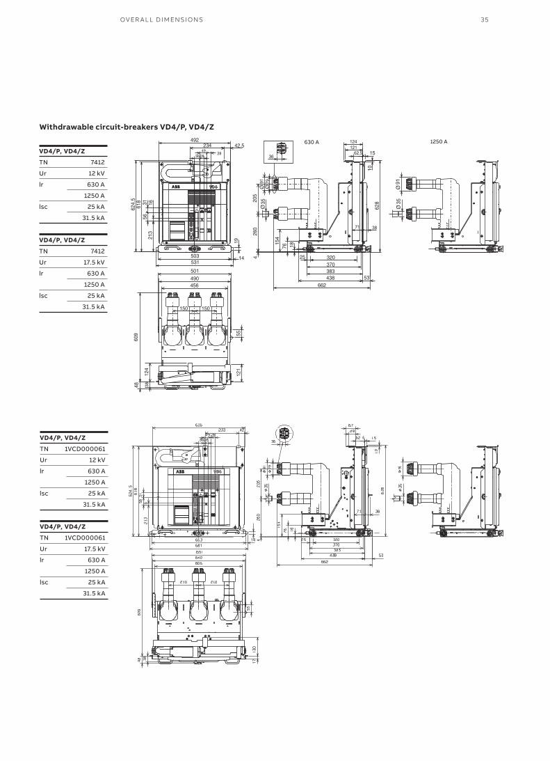
35OV ER A L L D I M ENSI O NS
VD4/P,VD4/Z
TN 7412
Ur 12 kV
lr 630 A
1250 A
lsc 25 kA
31.5 kA
VD4/P,VD4/Z
TN 7412
Ur 17.5 kV
lr 630 A
1250 A
lsc 25 kA
31.5 kA
VD4/P,VD4/Z
TN 1VCD000061
Ur 12 kV
lr 630 A
1250 A
lsc 25 kA
31.5 kA
VD4/P,VD4/Z
TN 1VCD000061
Ur 17.5 kV
lr 630 A
1250 A
lsc 25 kA
31.5 kA
Withdrawable circuit-breakers VD4/P, VD4/Z
630 A 1250 A
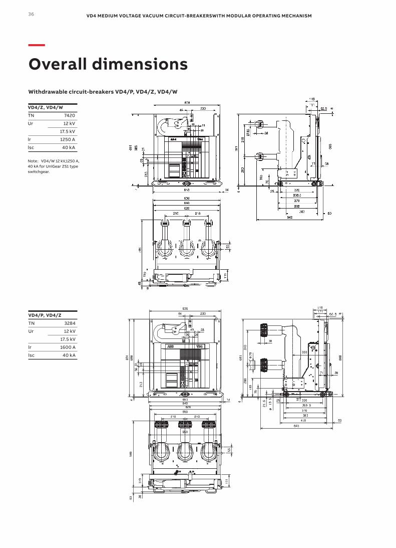
VD4 MEDIUM VOLTAGE VACUUM CIRCUIT-BREAKERSWITH MODULAR OPERATING MECHANISM36
—Overall dimensions
VD4/P,VD4/Z
TN 3284
Ur 12 kV
17.5 kV
lr 1600 A
lsc 40 kA
VD4/Z,VD4/W
TN 7420
Ur 12 kV
17.5 kV
lr 1250 A
lsc 40 kA
Note:VD4/W 12 kV,1250 A,40 kA for UniGear ZS1 type switchgear.
Withdrawable circuit-breakers VD4/P, VD4/Z, VD4/W
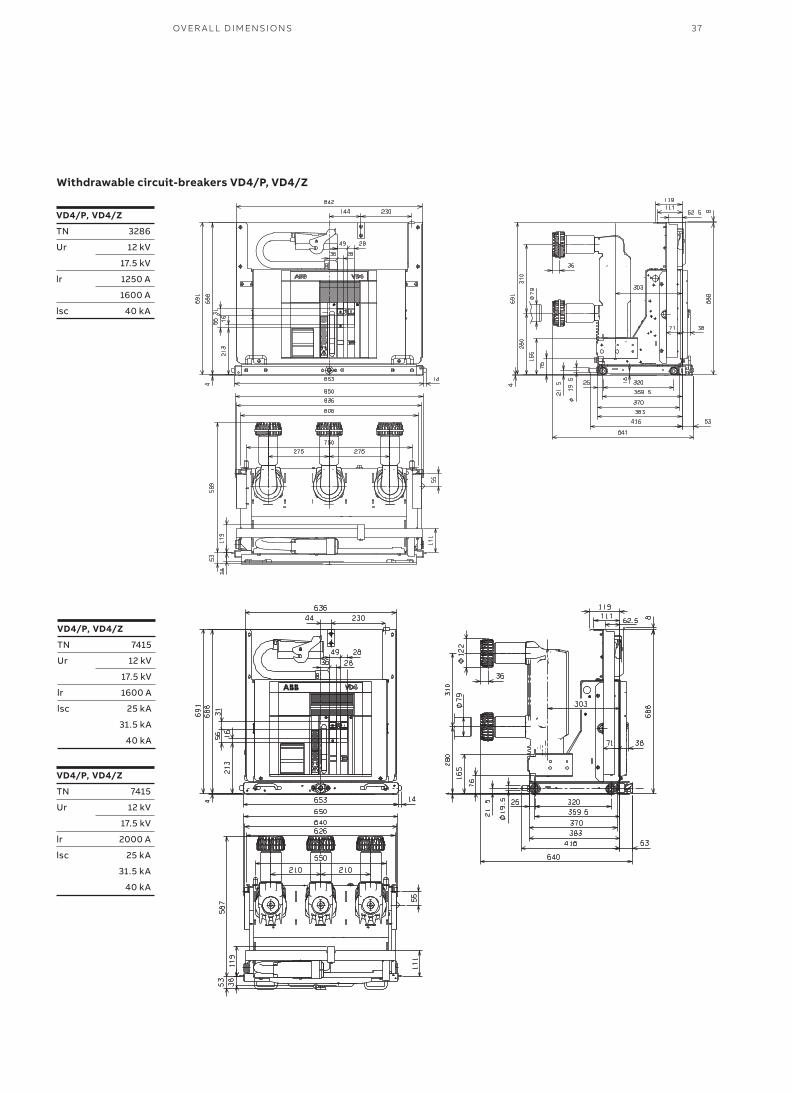
37OV ER A L L D I M ENSI O NS
VD4/P,VD4/Z
TN 3286
Ur 12 kV
17.5 kV
lr 1250 A
1600 A
lsc 40 kA
VD4/P,VD4/Z
TN 7415
Ur 12 kV
17.5 kV
lr 1600 A
lsc 25 kA
31.5 kA
40 kA
VD4/P,VD4/Z
TN 7415
Ur 12 kV
17.5 kV
lr 2000 A
lsc 25 kA
31.5 kA
40 kA
Withdrawable circuit-breakers VD4/P, VD4/Z
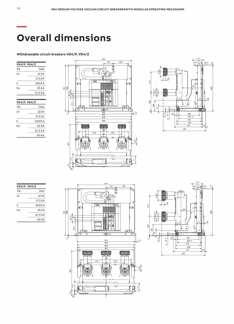
VD4 MEDIUM VOLTAGE VACUUM CIRCUIT-BREAKERSWITH MODULAR OPERATING MECHANISM38
—Overall dimensions
VD4/P,VD4/Z
TN 7417
Ur 12 kV
17.5 kV
lr 2500 A
lsc 25 kA
31.5 kA
40 kA
VD4/P,VD4/Z
TN 7416
Ur 12 kV
17.5 kV
lr 1600 A
lsc 25 kA
31.5 kA
VD4/P,VD4/Z
TN 7416
Ur 12 kV
17.5 kV
lr 2000 A
lsc 25 kA
31.5 kA
40 kA
Withdrawable circuit-breakers VD4/P, VD4/Z
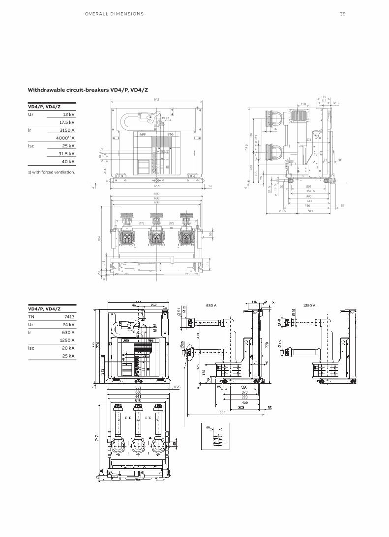
39OV ER A L L D I M ENSI O NS
VD4/P,VD4/Z
Ur 12 kV
17.5 kV
lr 3150 A
40001)A
lsc 25 kA
31.5 kA
40 kA
1) with forced ventilation.
VD4/P,VD4/Z
TN 7413
Ur 24 kV
lr 630 A
1250 A
lsc 20 kA
25 kA
630 A 1250 A
Withdrawable circuit-breakers VD4/P, VD4/Z
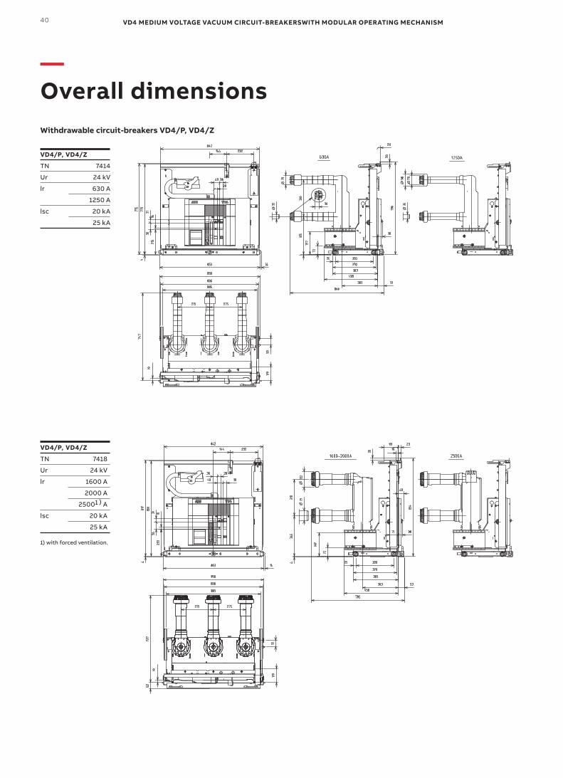
VD4 MEDIUM VOLTAGE VACUUM CIRCUIT-BREAKERSWITH MODULAR OPERATING MECHANISM40
—Overall dimensions
VD4/P,VD4/Z
TN 7418
Ur 24 kV
lr 1600 A
2000 A
25001)A
lsc 20 kA
25 kA
1) with forced ventilation.
VD4/P,VD4/Z
TN 7414
Ur 24 kV
lr 630 A
1250 A
lsc 20 kA
25 kA
Withdrawable circuit-breakers VD4/P, VD4/Z
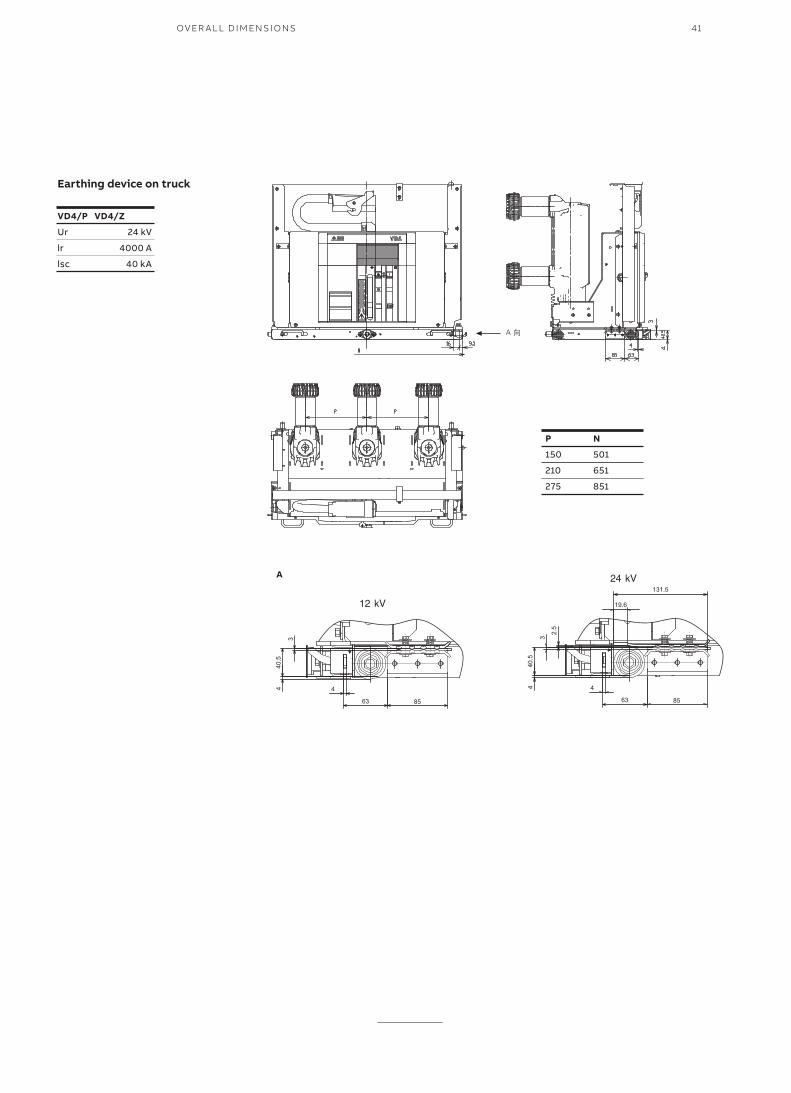
41OV ER A L L D I M ENSI O NS
VD4/P VD4/Z
Ur 24 kV
lr 4000 A
lsc 40 kA
Earthing device on truck
P N
150 501
210 651
275 851
A

VD4 MEDIUM VOLTAGE VACUUM CIRCUIT-BREAKERSWITH MODULAR OPERATING MECHANISM42
Diagrams for fixed circuit breaker 5NO-5NC
—Electrical circuit diagram
43
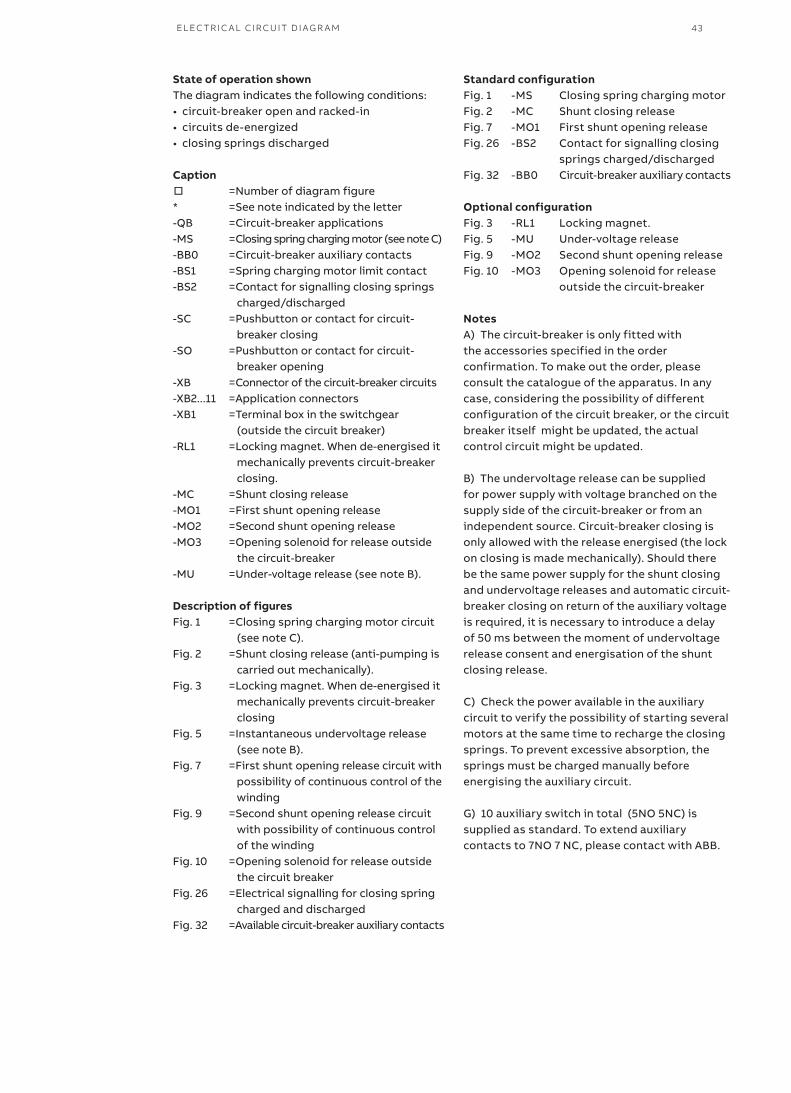
State of operation shownThe diagram indicates the following conditions:• circuit-breaker open and racked-in• circuits de-energized• closing springs discharged
Caption□ =Number of diagram figure* =See note indicated by the letter-QB =Circuit-breaker applications-MS =Closing spring charging motor (see note C)-BB0 =Circuit-breaker auxiliary contacts-BS1 =Spring charging motor limit contact-BS2 =Contact for signalling closing springs
charged/discharged-SC =Pushbutton or contact for circuit-
breaker closing-SO =Pushbutton or contact for circuit-
breaker opening-XB =Connector of the circuit-breaker circuits-XB2...11 =Application connectors-XB1 =Terminal box in the switchgear
(outside the circuit breaker)-RL1 =Locking magnet. When de-energised it
mechanically prevents circuit-breaker closing.
-MC =Shunt closing release-MO1 =First shunt opening release-MO2 =Second shunt opening release-MO3 =Opening solenoid for release outside
the circuit-breaker-MU =Under-voltage release (see note B).
Description of figuresFig. 1 =Closing spring charging motor circuit
(see note C).Fig. 2 =Shunt closing release (anti-pumping is
carried out mechanically).Fig. 3 =Locking magnet. When de-energised it
mechanically prevents circuit-breaker closing
Fig. 5 =Instantaneous undervoltage release (see note B).
Fig. 7 =First shunt opening release circuit with possibility of continuous control of the winding
Fig. 9 =Second shunt opening release circuit with possibility of continuous control of the winding
Fig. 10 =Opening solenoid for release outside the circuit breaker
Fig. 26 =Electrical signalling for closing spring charged and discharged
Fig. 32 =Available circuit-breaker auxiliary contacts
Standard configurationFig. 1 -MS Closing spring charging motorFig. 2 -MC Shunt closing releaseFig. 7 -MO1 First shunt opening releaseFig. 26 -BS2 Contact for signalling closing springs charged/dischargedFig. 32 -BB0 Circuit-breaker auxiliary contacts Optional configurationFig. 3 -RL1 Locking magnet.Fig. 5 -MU Under-voltage releaseFig. 9 -MO2 Second shunt opening releaseFig. 10 -MO3 Opening solenoid for release outside the circuit-breaker
NotesA) The circuit-breaker is only fitted with the accessories specified in the order confirmation. To make out the order, please consult the catalogue of the apparatus. In any case, considering the possibility of different configuration of the circuit breaker, or the circuit breaker itself might be updated, the actual control circuit might be updated.
B) The undervoltage release can be supplied for power supply with voltage branched on the supply side of the circuit-breaker or from an independent source. Circuit-breaker closing is only allowed with the release energised (the lock on closing is made mechanically). Should there be the same power supply for the shunt closing and undervoltage releases and automatic circuit-breaker closing on return of the auxiliary voltage is required, it is necessary to introduce a delay of 50 ms between the moment of undervoltage release consent and energisation of the shunt closing release.
C) Check the power available in the auxiliary circuit to verify the possibility of starting several motors at the same time to recharge the closing springs. To prevent excessive absorption, the springs must be charged manually before energising the auxiliary circuit.
G) 10 auxiliary switch in total (5NO 5NC) is supplied as standard. To extend auxiliary contacts to 7NO 7 NC, please contact with ABB.
EL EC TR I C A L CI R C U IT D I AG R A M
VD4 MEDIUM VOLTAGE VACUUM CIRCUIT-BREAKERSWITH MODULAR OPERATING MECHANISM44
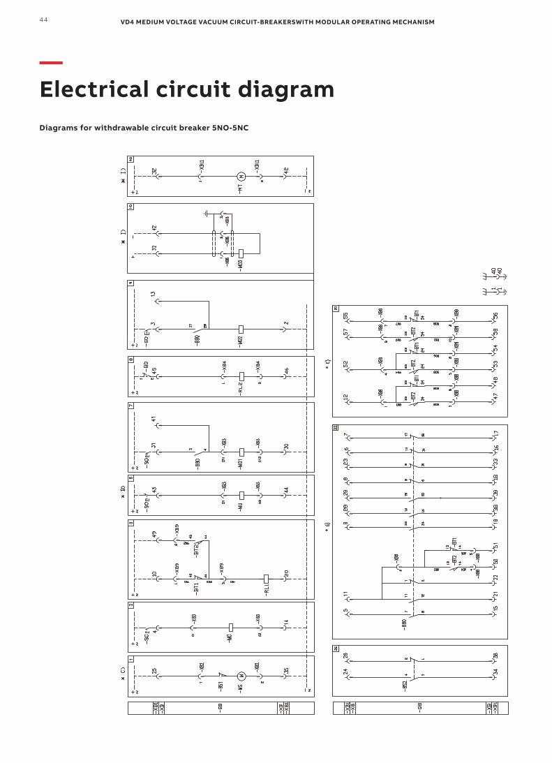
Diagrams for withdrawable circuit breaker 5NO-5NC
—Electrical circuit diagram
45
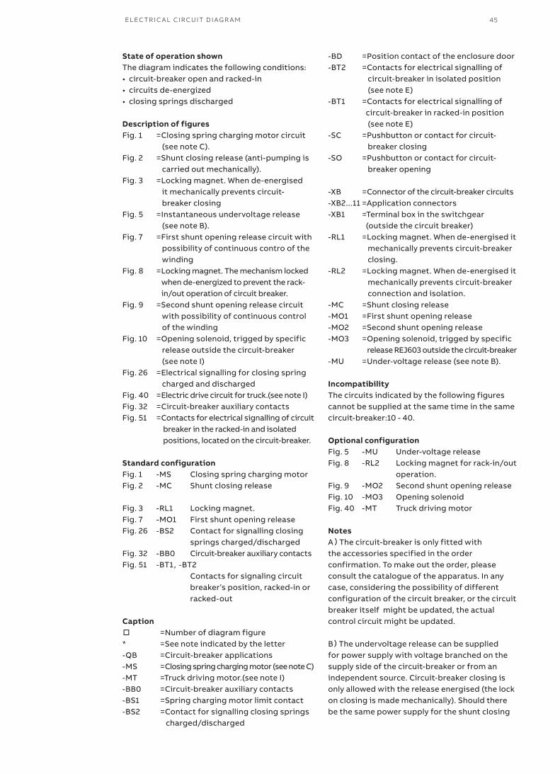
State of operation shownThe diagram indicates the following conditions:• circuit-breaker open and racked-in• circuits de-energized• closing springs discharged
Description of figuresFig. 1 =Closing spring charging motor circuit (see note C).Fig. 2 =Shunt closing release (anti-pumping is carried out mechanically).Fig. 3 =Locking magnet. When de-energised it mechanically prevents circuit- breaker closingFig. 5 =Instantaneous undervoltage release (see note B).Fig. 7 =First shunt opening release circuit with possibility of continuous contro of the winding Fig. 8 =Locking magnet. The mechanism locked when de-energized to prevent the rack- in/out operation of circuit breaker.Fig. 9 =Second shunt opening release circuit with possibility of continuous control of the winding Fig. 10 =Opening solenoid, trigged by specific release outside the circuit-breaker (see note I)Fig. 26 =Electrical signalling for closing spring charged and discharged Fig. 40 =Electric drive circuit for truck.(see note I)Fig. 32 =Circuit-breaker auxiliary contactsFig. 51 =Contacts for electrical signalling of circuit breaker in the racked-in and isolated positions, located on the circuit-breaker.
Standard configurationFig. 1 -MS Closing spring charging motorFig. 2 -MC Shunt closing release
Fig. 3 -RL1 Locking magnet.Fig. 7 -MO1 First shunt opening releaseFig. 26 -BS2 Contact for signalling closing springs charged/dischargedFig. 32 -BB0 Circuit-breaker auxiliary contactsFig. 51 -BT1,-BT2 Contacts for signaling circuit breaker’s position, racked-in or racked-out
Caption□ =Number of diagram figure* =See note indicated by the letter-QB =Circuit-breaker applications-MS =Closing spring charging motor (see note C)-MT =Truck driving motor.(see note I)-BB0 =Circuit-breaker auxiliary contacts-BS1 =Spring charging motor limit contact-BS2 =Contact for signalling closing springs charged/discharged
-BD =Position contact of the enclosure door-BT2 =Contacts for electrical signalling of circuit-breaker in isolated position (see note E)-BT1 =Contacts for electrical signalling of circuit-breaker in racked-in position (see note E)-SC =Pushbutton or contact for circuit- breaker closing-SO =Pushbutton or contact for circuit- breaker opening
-XB =Connector of the circuit-breaker circuits-XB2...11 =Application connectors-XB1 =Terminal box in the switchgear (outside the circuit breaker)-RL1 =Locking magnet. When de-energised it mechanically prevents circuit-breaker closing.-RL2 =Locking magnet. When de-energised it mechanically prevents circuit-breaker connection and isolation. -MC =Shunt closing release -MO1 =First shunt opening release-MO2 =Second shunt opening release-MO3 =Opening solenoid, trigged by specific release REJ603 outside the circuit-breaker-MU =Under-voltage release (see note B).
IncompatibilityThe circuits indicated by the following figures cannot be supplied at the same time in the same circuit-breaker:10 - 40.
Optional configurationFig. 5 -MU Under-voltage releaseFig. 8 -RL2 Locking magnet for rack-in/out operation.Fig. 9 -MO2 Second shunt opening releaseFig. 10 -MO3 Opening solenoidFig. 40 -MT Truck driving motor
NotesA)The circuit-breaker is only fitted with the accessories specified in the order confirmation. To make out the order, please consult the catalogue of the apparatus. In any case, considering the possibility of different configuration of the circuit breaker, or the circuit breaker itself might be updated, the actual control circuit might be updated.
B)The undervoltage release can be supplied for power supply with voltage branched on the supply side of the circuit-breaker or from an independent source. Circuit-breaker closing is only allowed with the release energised (the lock on closing is made mechanically). Should there be the same power supply for the shunt closing
EL EC TR I C A L CI R C U IT D I AG R A M
VD4 MEDIUM VOLTAGE VACUUM CIRCUIT-BREAKERSWITH MODULAR OPERATING MECHANISM46
and undervoltage releases and automatic circuit-breaker closing on return of the auxiliary voltage is required, it is necessary to introduce a delay of 50 ms between the moment of undervoltage release consent and energisation of the shunt closing release.
C)Check the power available in the auxiliary circuit to verify the possibility of starting several motors at the same time to recharge the closing springs. To prevent excessive absorption, the springs must be charged manually before energising the auxiliary circuit.
E) The contacts for electrical signalling of circuitbreaker in the racked-in and isolated position (- BT1 and -BT2) shown in figs. 51 are located on the circuit-breaker (moving part).
G) 10 auxiliary switch in total (5NO 5NC) is supplied as standard. To extend auxiliary contacts to 7NO 7 NC, please contact with ABB.
I)Fig. 10 and Fig. 40 can not be chosen simultaneously, that is, truck driving motor -MT and Opening solenoid -MO3 should not be chosen at the same time.
—Electrical circuit diagram
47
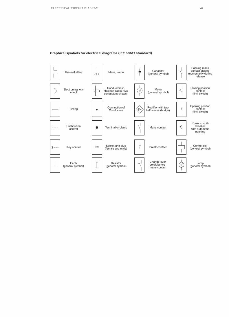
Graphical symbols for electrical diagrams (IEC 60617 standard)
Passing makecontact closing
momentarily duringrelease
EL EC TR I C A L CI R C U IT D I AG R A M
Pu
blic
atio
n N
o: 1
YH
A0
00
09
1-R
ev.
C, e
n, 2
017
07
—ABB Xiamen Switchgear Co., Ltd.ABB Industrial Park, Torch High-Tech Zone, No. 319,Xiamen, Fujian, P.R.ChinaTel: +86 592 602 6033Fax: +86 592 603 0505Zip Code: 361006Service Hotline: 800-820-9696 400-820-9696
www.abb.com.cn/mv
We reserve the right to make changes in the course of technical development