Embed Size (px)
Citation preview

2 3
Meeting the Demands of Technically Advanced Clients
ZKL pays proper attention to technical development of products and investments in new technologies in order to meet the demands of technically advanced clients. As a result of one of fundamental innovations in recent time is launching gradual production start of ZKL bearings of higher standard with NEW FORCE designation.
By introducing the production of New Force bearings ZKL thus follows up with the already materialized innovation phase of spherical roller bearings with steel sheet and brass machined cages. This initiated process will result in serial production representing approximately 50 percent of total assortment of ZKL roller bearings in category New Force in year 2010.
– Switch over to New Force –
ZKL presents its new standard of roller bearingsNew Force bearings constitute a new generation of ZKL bearings. The application of these bearings brings longer service life of bear-
ings, higher operation safety, prolongation of service intervals and thus a substantial reduction of operational cost for users. New Force bearings are designed for most challenging mountings in transmission boxes, in railway vehicles, presses, rolling mills, paper mill machines, pumps, machine tools, power units, in printing industry and similar.
As a first complex series of New Force bearings there are being introduced on the market radial spherical roller bearings for heavy duty operating conditions where use of standard bearings with steel sheet cage is not recommended. These new ZKL bearings are in execution with prong-type brass machined cage (EMH version).
4 5
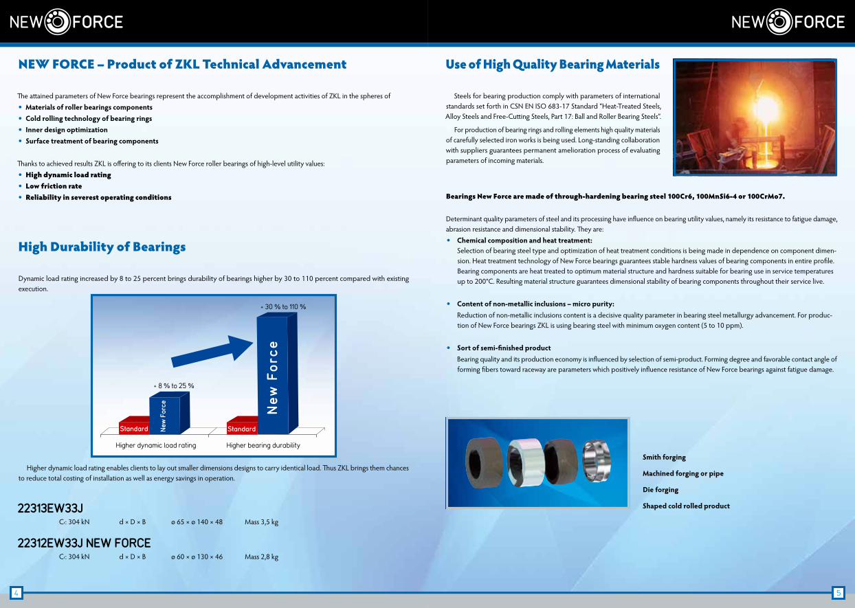
Use of High Quality Bearing Materials
Steels for bearing production comply with parameters of international standards set forth in CSN EN ISO 683-17 Standard “Heat-Treated Steels, Alloy Steels and Free-Cutting Steels, Part 17: Ball and Roller Bearing Steels”.
For production of bearing rings and rolling elements high quality materials of carefully selected iron works is being used. Long-standing collaboration with suppliers guarantees permanent amelioration process of evaluating parameters of incoming materials.
Bearings New Force are made of through-hardening bearing steel 100Cr6, 100MnSi6-4 or 100CrMo7.
Determinant quality parameters of steel and its processing have influence on bearing utility values, namely its resistance to fatigue damage, abrasion resistance and dimensional stability. They are: • Chemical composition and heat treatment:
Selection of bearing steel type and optimization of heat treatment conditions is being made in dependence on component dimen-sion. Heat treatment technology of New Force bearings guarantees stable hardness values of bearing components in entire profile. Bearing components are heat treated to optimum material structure and hardness suitable for bearing use in service temperatures up to 200°C. Resulting material structure guarantees dimensional stability of bearing components throughout their service live.
• Content of non-metallic inclusions – micro purity: Reduction of non-metallic inclusions content is a decisive quality parameter in bearing steel metallurgy advancement. For produc-
tion of New Force bearings ZKL is using bearing steel with minimum oxygen content (5 to 10 ppm).
• Sort of semi-finished product Bearing quality and its production economy is influenced by selection of semi-product. Forming degree and favorable contact angle of
forming fibers toward raceway are parameters which positively influence resistance of New Force bearings against fatigue damage.
Higher dynamic load rating enables clients to lay out smaller dimensions designs to carry identical load. Thus ZKL brings them chances to reduce total costing of installation as well as energy savings in operation.
NEW FORCE – Product of ZKL Technical Advancement
The attained parameters of New Force bearings represent the accomplishment of development activities of ZKL in the spheres of • Materials of roller bearings components • Cold rolling technology of bearing rings • Inner design optimization • Surface treatment of bearing components
Thanks to achieved results ZKL is offering to its clients New Force roller bearings of high-level utility values: • High dynamic load rating • Low friction rate • Reliability in severest operating conditions
High Durability of Bearings
Dynamic load rating increased by 8 to 25 percent brings durability of bearings higher by 30 to 110 percent compared with existing execution.
Higher dynamic load rating
+ 8 % to 25 %
+ 30 % to 110 %
Standard New
For
ce
Standard
New
For
ce
Higher bearing durability
22313EW33J Cr: 304 kN d × D × B ø 65 × ø 140 × 48 Mass 3,5 kg
22312EW33J NEW FORCE Cr: 304 kN d × D × B ø 60 × ø 130 × 46 Mass 2,8 kg
Smith forging
Machined forging or pipe
Die forging
Shaped cold rolled product
6 7
Scheme of bearing rings cold rolling principle
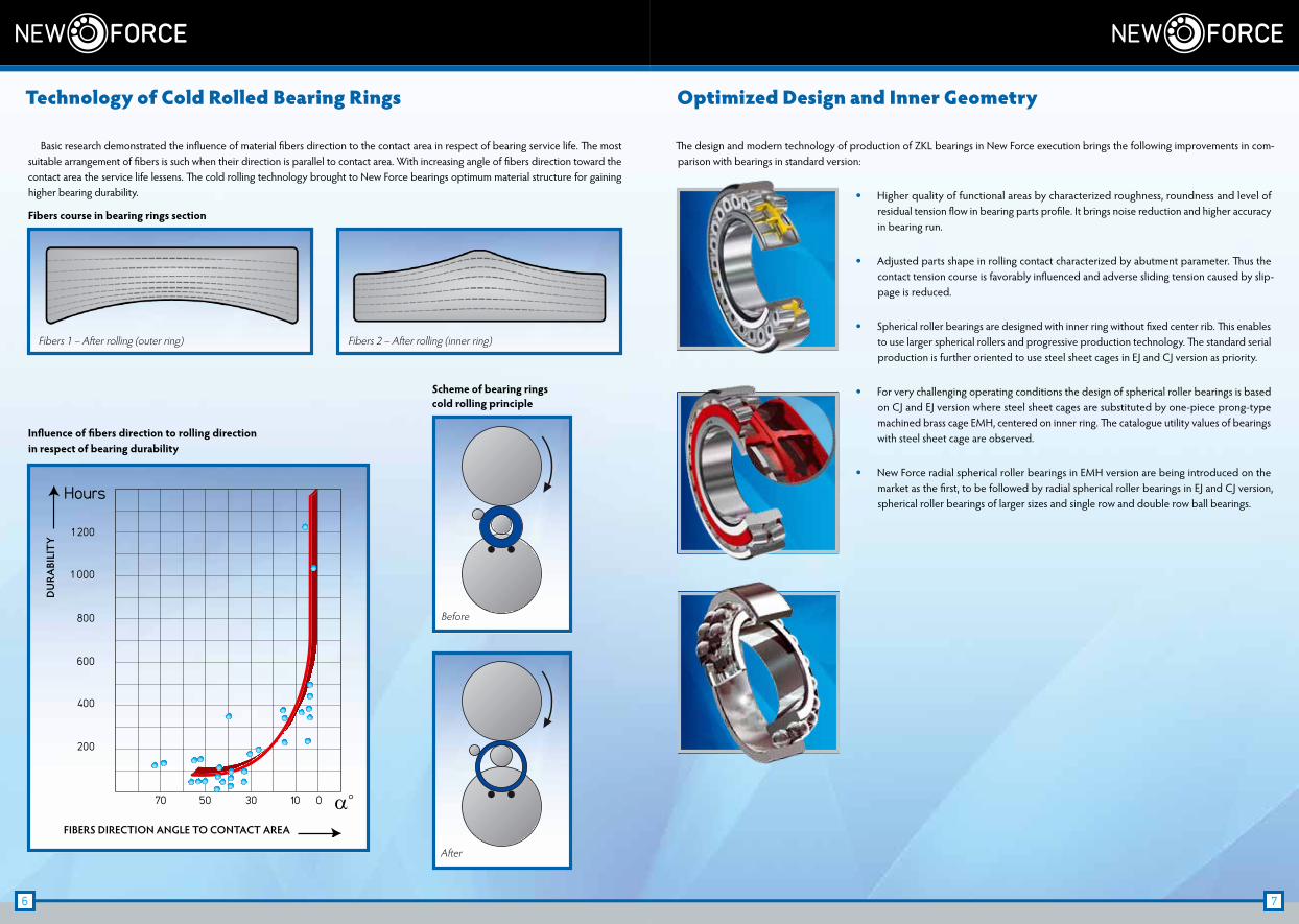
Optimized Design and Inner Geometry
The design and modern technology of production of ZKL bearings in New Force execution brings the following improvements in com-parison with bearings in standard version:
• Higher quality of functional areas by characterized roughness, roundness and level of residual tension flow in bearing parts profile. It brings noise reduction and higher accuracy in bearing run.
• Adjusted parts shape in rolling contact characterized by abutment parameter. Thus the contact tension course is favorably influenced and adverse sliding tension caused by slip-page is reduced.
• Spherical roller bearings are designed with inner ring without fixed center rib. This enables to use larger spherical rollers and progressive production technology. The standard serial production is further oriented to use steel sheet cages in EJ and CJ version as priority.
• For very challenging operating conditions the design of spherical roller bearings is based on CJ and EJ version where steel sheet cages are substituted by one-piece prong-type machined brass cage EMH, centered on inner ring. The catalogue utility values of bearings with steel sheet cage are observed.
• New Force radial spherical roller bearings in EMH version are being introduced on the market as the first, to be followed by radial spherical roller bearings in EJ and CJ version, spherical roller bearings of larger sizes and single row and double row ball bearings.
Fibers course in bearing rings section
Technology of Cold Rolled Bearing Rings
Basic research demonstrated the influence of material fibers direction to the contact area in respect of bearing service life. The most suitable arrangement of fibers is such when their direction is parallel to contact area. With increasing angle of fibers direction toward the contact area the service life lessens. The cold rolling technology brought to New Force bearings optimum material structure for gaining higher bearing durability.
70
200
400
600
800
1 000
1 200
Hours
50 30 10 0
DU
RABI
LIT
Y
FIBERS DIRECTION ANGLE TO CONTACT AREA
α°
Fibers 1 – After rolling (outer ring)
Before
After
Fibers 2 – After rolling (inner ring)
Influence of fibers direction to rolling direction in respect of bearing durability
8 9
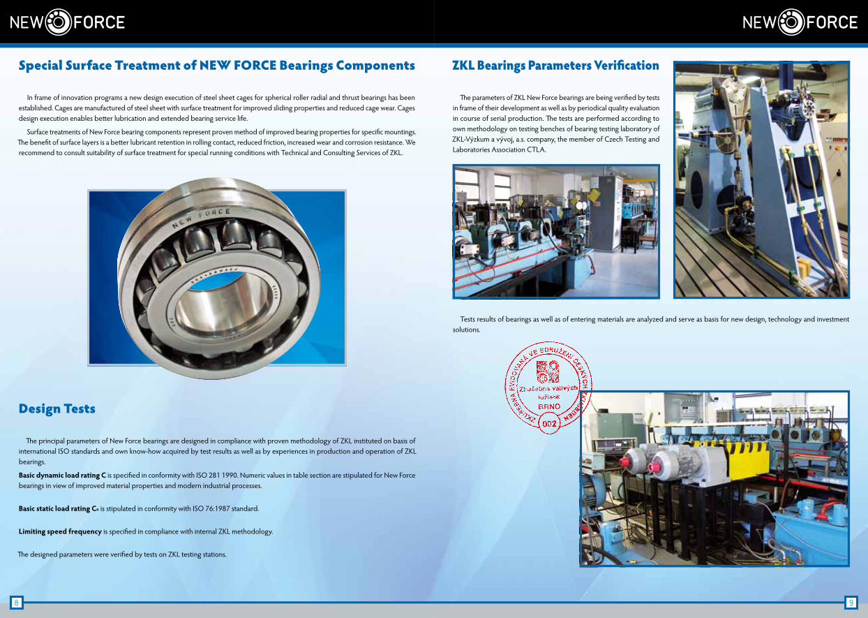
ZKL Bearings Parameters Verification
The parameters of ZKL New Force bearings are being verified by tests in frame of their development as well as by periodical quality evaluation in course of serial production. The tests are performed according to own methodology on testing benches of bearing testing laboratory of ZKL-Výzkum a vývoj, a.s. company, the member of Czech Testing and Laboratories Association CTLA.
Tests results of bearings as well as of entering materials are analyzed and serve as basis for new design, technology and investment solutions.
Special Surface Treatment of NEW FORCE Bearings Components
In frame of innovation programs a new design execution of steel sheet cages for spherical roller radial and thrust bearings has been established. Cages are manufactured of steel sheet with surface treatment for improved sliding properties and reduced cage wear. Cages design execution enables better lubrication and extended bearing service life.
Surface treatments of New Force bearing components represent proven method of improved bearing properties for specific mountings. The benefit of surface layers is a better lubricant retention in rolling contact, reduced friction, increased wear and corrosion resistance. We recommend to consult suitability of surface treatment for special running conditions with Technical and Consulting Services of ZKL.
Design Tests
The principal parameters of New Force bearings are designed in compliance with proven methodology of ZKL instituted on basis of international ISO standards and own know-how acquired by test results as well as by experiences in production and operation of ZKL bearings.
Basic dynamic load rating C is specified in conformity with ISO 281 1990. Numeric values in table section are stipulated for New Force bearings in view of improved material properties and modern industrial processes.
Basic static load rating Co is stipulated in conformity with ISO 76:1987 standard.
Limiting speed frequency is specified in compliance with internal ZKL methodology.
The designed parameters were verified by tests on ZKL testing stations.

10 11
ZKL Training Center – Support of Technical Advancement
ZKL training center performs a wide spectrum of educational and training programs both for employees of ZKL companies as well as for technicians of important clients. Permanent education and qualification growth of own professionals and technicians of roller bearings users is fundamental prerequisite for practical utilization of new bearings benefits.
First of all the contemporarily equipped lecture rooms permit to practically implement modern technology and metrology processes for production of new and more accurate bearings ZKL New Force.
Technical Support of ZKL Bearings Users
For solution of clients’ needs the Technical and Consulting Services center (TCS) is fully at disposal. Its professionals are prepared to operatively solve requirements and questions of ZKL bearings users regarding rolling arrangement and mounting. TCS renders informa-tion to clients in the field of bearings, their accessories and tribology.
Upon user’s request TCS performs technical super-vision in mounting and dismounting of bearings at the client and gives special training courses for users’ staff in newly built training center. TCS cooperates with manufacturers in development of rolling arrangement. It elaborates technical expertise of bearings break downs. It determines reasons of break downs and suggests measures for their prevention.
Practical experiences in ZKL bearings operation became relevant inducement in New Force bear-ings design.
12 13
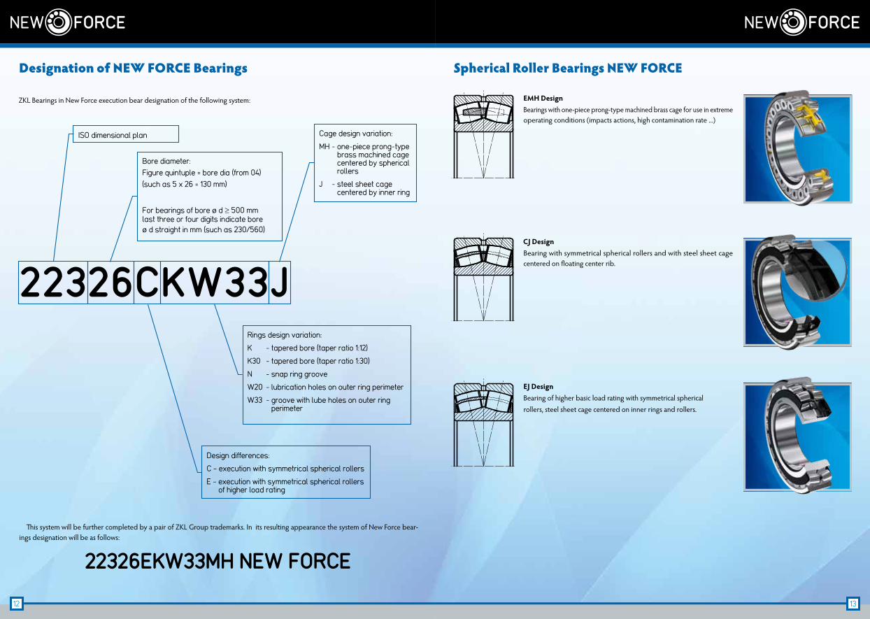
Spherical Roller Bearings NEW FORCE
EMH DesignBearings with one-piece prong-type machined brass cage for use in extreme operating conditions (impacts actions, high contamination rate ...)
CJ DesignBearing with symmetrical spherical rollers and with steel sheet cage centered on floating center rib.
EJ DesignBearing of higher basic load rating with symmetrical spherical rollers, steel sheet cage centered on inner rings and rollers.
This system will be further completed by a pair of ZKL Group trademarks. In its resulting appearance the system of New Force bear-ings designation will be as follows:
22326EKW33MH NEW FORCE
Designation of NEW FORCE Bearings
ZKL Bearings in New Force execution bear designation of the following system:
22326CKW33J
ISO dimensional plan
Bore diameter:Figure quintuple = bore dia (from 04)(such as 5 x 26 = 130 mm)
For bearings of bore ø d ≥ 500 mm last three or four digits indicate bore ø d straight in mm (such as 230/560)
Rings design variation:
K - tapered bore (taper ratio 1:12)
K30 - tapered bore (taper ratio 1:30)
N - snap ring groove
W20 - lubrication holes on outer ring perimeter
W33 - groove with lube holes on outer ring perimeter
Design differences:
C – execution with symmetrical spherical rollers
E – execution with symmetrical spherical rollers of higher load rating
Cage design variation:
MH - one-piece prong-type brass machined cage centered by spherical rollers
J - steel sheet cage centered by inner ring
14 15
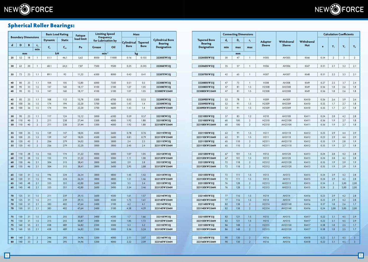
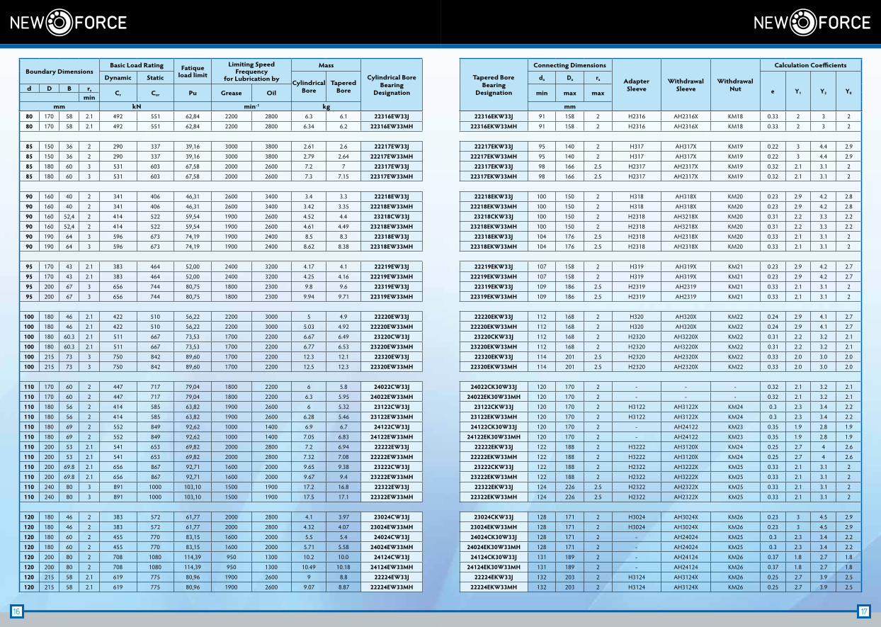
Boundary DimensionsBasic Load Rating Fatique
load limit
Limiting Speed Frequency
for Lubrication by
Mass
Cylindrical BoreBearing
Designation
Tapered BoreBearing
Designation
Connecting Dimensions
AdapterSleeve
WithdrawalSleeve
WithdrawalNut
Calculation Coefficients
Dynamic StaticCylindrical
BoreTapered
Bore
da Da ra
e Y1 Y2 Y0d D B rs Cr Cor Pu Grease Oil min max max
minmm kN min-1 kg mm
25 52 18 1 51.1 46,1 5,62 8500 11000 0.16 0.155 22205EW33J 22205EKW33J 30 47 1 H305 AH305 KM6 0.34 2 3 2
30 62 20 1 68.1 64,5 7,87 7500 9500 0.25 0.245 22206EW33J 22206EKW33J 35 57 1 H306 AH306 KM7 0.31 2.1 3.2 2.1
35 72 23 1.1 89.1 92 11,22 6300 8000 0.42 0.41 22207EW33J 22207EKW33J 42 65 1 H307 AH307 KM8 0.31 2.2 3.3 2.1
40 80 23 1.1 104 105 12,80 6000 7500 0.51 0.5 22208EW33J 22208EKW33J 47 73 1 H308 AH308 KM9 0.27 2.5 3.7 2.4
40 90 33 1.5 147 160 18,17 4100 5100 1.07 1.05 22308EW33J 22308EKW33J 47 81 1.5 H2308 AH2308 KM9 0.36 1.8 2.6 1.8
40 90 33 1.5 147 160 18,17 4100 5100 1.07 1.05 22308EW33MH 22308EKW33MH 47 81 1.5 H2308 AH2308 KM9 0.36 1.8 2.6 1.8
45 85 23 1.1 108 113 13,78 5300 6700 0.55 0.53 22209EW33J 22209EKW33J 52 78 1 H309 AH309 KM10 0.26 2.6 3.9 2.6
45 100 36 1.5 174 194 22,20 3700 4600 1.43 1.4 22309EW33J 22309EKW33J 52 91 1.5 H2309 AH2309 KM10 0.35 1.7 2.7 1.8
45 100 36 1.5 174 194 22,20 3700 4600 1.43 1.4 22309EW33MH 22309EKW33MH 52 91 1.5 H2309 AH2309 KM10 0.35 1.7 2.7 1.8
50 90 23 1.1 117 124 15,12 5000 6300 0.59 0.57 22210EW33J 22210EKW33J 57 83 1.2 H310 AH310X KM11 0.24 2.8 4.2 2.8
50 110 40 2 211 238 27,44 3300 4000 1.92 1.88 22310EW33J 22310EKW33J 60 100 2 H2310 AH2310X KM11 0.36 1.9 2.7 1.8
50 110 40 2 211 238 27,44 3300 4000 1.92 1.88 22310EW33MH 22310EKW33MH 60 100 2 H2310 AH2310X KM11 0.36 1.9 2.7 1.8
55 100 25 1.5 139 147 18,05 4500 5600 0.78 0.76 22211EW33J 22211EKW33J 62 91 1.5 H311 AH311X KM12 0.23 2.9 4.4 2.9
55 100 25 1.5 139 147 18,05 4500 5600 0.81 0.79 22211EW33MH 22211EKW33MH 62 91 1.5 H311 AH311X KM12 0.23 2.9 4.4 2.9
55 120 43 2 256 279 34,02 3000 3800 2.4 2.3 22311EW33J 22311EKW33J 65 110 2 H2311 AH2311X KM12 0.35 1.9 2.8 1.9
55 120 43 2 256 279 32,20 3000 3800 2.45 2.4 22311EW33MH 22311EKW33MH 65 110 2 H2311 AH2311X KM12 0.35 1.9 2.7 1.8
60 110 28 1.5 155 174 21,22 4000 5000 1.07 1.05 22212EW33J 22212EKW33J 67 101 1.5 H312 AH312X KM13 0.24 2.8 4.2 2.8
60 110 28 1.5 155 174 21,22 4000 5000 1.11 1.08 22212EW33MH 22212EKW33MH 67 101 1.5 H312 AH312X KM13 0.24 2.8 4.2 2.8
60 130 46 2.1 304 315 38,41 2800 3600 2.9 2.8 22312EW33J 22312EKW33J 72 118 2 H2312 AH2312X KM13 0.35 1.9 2.9 1.9
60 130 46 2.1 304 315 38,41 2800 3600 2,95 2,88 22312EW33MH 22312EKW33MH 72 118 2 H2312 AH2312X KM13 0.35 1.9 2.9 1.9
65 120 31 1.5 196 224 26,34 3800 4800 1.45 1.42 22213EW33J 22213EKW33J 72 111 1.5 H313 AH313 KM15 0.24 2.9 4.2 2.8
65 120 31 1.5 196 224 26,34 3800 4800 1.51 1.46 22213EW33MH 22213EKW33MH 72 111 1.5 H313 AH313 KM15 0.24 2.9 4.2 2.8
65 140 48 2.1 335 351 42,80 2600 3400 3.5 3.4 22313EW33J 22313EKW33J 76 128 2 H2313 AH2313 KM15 0.34 2 3,00 2,00
65 140 48 2.1 335 351 42,80 2600 3400 3.54 3.46 22313EW33MH 22313EKW33MH 76 128 2 H2313 AH2313 KM15 0.34 2 3,00 2,00
70 125 31 1.5 211 239 29,15 3600 4500 1.61 1.57 22214EW33J 22214EKW33J 77 116 1.5 H314 AH314 KM16 0.23 2.9 4.2 2.8
70 125 31 1.5 211 239 29,15 3600 4500 1.73 1.61 22214EW33MH 22214EKW33MH 77 116 1.5 H314 AH314 KM16 0.23 2.9 4.2 2.8
70 150 51 2.1 383 402 47,64 2400 3100 4.2 4.1 22314EW33J 22314EKW33J 82 138 2 H2314 AH2314X KM16 0.37 1.8 2.6 1.7
70 150 51 2.1 383 402 47,64 2400 3100 4.38 4.29 22314EW33MH 22314EKW33MH 82 138 2 H2314 AH2314X KM16 0,34 2,00 3,00 2,00
75 130 31 1.5 215 255 30,87 3400 4300 1.7 1.66 22215EW33J 22215EKW33J 82 121 1.5 H315 AH315 KM17 0.22 3.1 4.5 2.9
75 130 31 1.5 215 255 30,87 3400 4300 1.85 1.72 22215EW33MH 22215EKW33MH 82 121 1.5 H315 AH315 KM17 0.22 3.1 4.5 2.9
75 160 55 2.1 438 489 56,82 2300 3000 5.3 5.2 22315EW33J 22315EKW33J 86 148 2 H2315 AH2315X KM17 0.38 1.8 2.5 1.7
75 160 55 2.1 438 489 56,82 2300 3000 5.36 5.24 22315EW33MH 22315EKW33MH 86 148 2 H2315 AH2315X KM17 0.38 1.8 2.5 1.7
80 140 33 2 246 295 34,96 3200 4000 2.11 2.07 22216EW33J 22216EKW33J 90 130 2 H316 AH316 KM18 0.22 3.1 4.5 3
80 140 33 2 246 295 34,96 3200 4000 2.22 2.09 22216EW33MH 22216EKW33MH 90 130 2 H316 AH316 KM18 0.22 3.1 4.5 3
Spherical Roller Bearings:
16 17
80 170 58 2.1 492 551 62,84 2200 2800 6.3 6.1 22316EW33J 22316EKW33J 91 158 2 H2316 AH2316X KM18 0.33 2 3 2
80 170 58 2.1 492 551 62,84 2200 2800 6.34 6.2 22316EW33MH 22316EKW33MH 91 158 2 H2316 AH2316X KM18 0.33 2 3 2
85 150 36 2 290 337 39,16 3000 3800 2.61 2.6 22217EW33J 22217EKW33J 95 140 2 H317 AH317X KM19 0.22 3 4.4 2.9
85 150 36 2 290 337 39,16 3000 3800 2.79 2.64 22217EW33MH 22217EKW33MH 95 140 2 H317 AH317X KM19 0.22 3 4.4 2.9
85 180 60 3 531 603 67,58 2000 2600 7.2 7 22317EW33J 22317EKW33J 98 166 2.5 H2317 AH2317X KM19 0.32 2.1 3.1 2
85 180 60 3 531 603 67,58 2000 2600 7.3 7.15 22317EW33MH 22317EKW33MH 98 166 2.5 H2317 AH2317X KM19 0.32 2.1 3.1 2
90 160 40 2 341 406 46,31 2600 3400 3.4 3.3 22218EW33J 22218EKW33J 100 150 2 H318 AH318X KM20 0.23 2.9 4.2 2.8
90 160 40 2 341 406 46,31 2600 3400 3.42 3.35 22218EW33MH 22218EKW33MH 100 150 2 H318 AH318X KM20 0.23 2.9 4.2 2.8
90 160 52,4 2 414 522 59,54 1900 2600 4.52 4.4 23218CW33J 23218CKW33J 100 150 2 H2318 AH3218X KM20 0.31 2.2 3.3 2.2
90 160 52,4 2 414 522 59,54 1900 2600 4.61 4.49 23218EW33MH 23218EKW33MH 100 150 2 H2318 AH3218X KM20 0.31 2.2 3.3 2.2
90 190 64 3 596 673 74,19 1900 2400 8.5 8.3 22318EW33J 22318EKW33J 104 176 2.5 H2318 AH2318X KM20 0.33 2.1 3.1 2
90 190 64 3 596 673 74,19 1900 2400 8.62 8.38 22318EW33MH 22318EKW33MH 104 176 2.5 H2318 AH2318X KM20 0.33 2.1 3.1 2
95 170 43 2.1 383 464 52,00 2400 3200 4.17 4.1 22219EW33J 22219EKW33J 107 158 2 H319 AH319X KM21 0.23 2.9 4.2 2.7
95 170 43 2.1 383 464 52,00 2400 3200 4.25 4.16 22219EW33MH 22219EKW33MH 107 158 2 H319 AH319X KM21 0.23 2.9 4.2 2.7
95 200 67 3 656 744 80,75 1800 2300 9.8 9.6 22319EW33J 22319EKW33J 109 186 2.5 H2319 AH2319 KM21 0.33 2.1 3.1 2
95 200 67 3 656 744 80,75 1800 2300 9.94 9.71 22319EW33MH 22319EKW33MH 109 186 2.5 H2319 AH2319 KM21 0.33 2.1 3.1 2
100 180 46 2.1 422 510 56,22 2200 3000 5 4.9 22220EW33J 22220EKW33J 112 168 2 H320 AH320X KM22 0.24 2.9 4.1 2.7
100 180 46 2.1 422 510 56,22 2200 3000 5.03 4.92 22220EW33MH 22220EKW33MH 112 168 2 H320 AH320X KM22 0.24 2.9 4.1 2.7
100 180 60.3 2.1 511 667 73,53 1700 2200 6.67 6.49 23220CW33J 23220CKW33J 112 168 2 H2320 AH3220X KM22 0.31 2.2 3.2 2.1
100 180 60.3 2.1 511 667 73,53 1700 2200 6.77 6.53 23220EW33MH 23220EKW33MH 112 168 2 H2320 AH3220X KM22 0.31 2.2 3.2 2.1
100 215 73 3 750 842 89,60 1700 2200 12.3 12.1 22320EW33J 22320EKW33J 114 201 2.5 H2320 AH2320X KM22 0.33 2.0 3.0 2.0
100 215 73 3 750 842 89,60 1700 2200 12.5 12.3 22320EW33MH 22320EKW33MH 114 201 2.5 H2320 AH2320X KM22 0.33 2.0 3.0 2.0
110 170 60 2 447 717 79,04 1800 2200 6 5.8 24022CW33J 24022CK30W33J 120 170 2 - - - 0.32 2.1 3.2 2.1
110 170 60 2 447 717 79,04 1800 2200 6.3 5.95 24022EW33MH 24022EK30W33MH 120 170 2 - - - 0.32 2.1 3.2 2.1
110 180 56 2 414 585 63,82 1900 2600 6 5.32 23122CW33J 23122CKW33J 120 170 2 H3122 AH3122X KM24 0.3 2.3 3.4 2.2
110 180 56 2 414 585 63,82 1900 2600 6.28 5.46 23122EW33MH 23122EKW33MH 120 170 2 H3122 AH3122X KM24 0.3 2.3 3.4 2.2
110 180 69 2 552 849 92,62 1000 1400 6.9 6.7 24122CW33J 24122CK30W33J 120 170 2 - AH24122 KM23 0.35 1.9 2.8 1.9
110 180 69 2 552 849 92,62 1000 1400 7.05 6.83 24122EW33MH 24122EK30W33MH 120 170 2 - AH24122 KM23 0.35 1.9 2.8 1.9
110 200 53 2.1 541 653 69,82 2000 2800 7.2 6.94 22222EW33J 22222EKW33J 122 188 2 H3222 AH3120X KM24 0.25 2.7 4 2.6
110 200 53 2.1 541 653 69,82 2000 2800 7.32 7.08 22222EW33MH 22222EKW33MH 122 188 2 H3222 AH3120X KM24 0.25 2.7 4 2.6
110 200 69.8 2.1 656 867 92,71 1600 2000 9.65 9.38 23222CW33J 23222CKW33J 122 188 2 H2322 AH3222X KM25 0.33 2.1 3.1 2
110 200 69.8 2.1 656 867 92,71 1600 2000 9.67 9.4 23222EW33MH 23222EKW33MH 122 188 2 H2322 AH3222X KM25 0.33 2.1 3.1 2
110 240 80 3 891 1000 103,10 1500 1900 17.2 16.8 22322EW33J 22322EKW33J 124 226 2.5 H2322 AH2322X KM25 0.33 2.1 3.1 2
110 240 80 3 891 1000 103,10 1500 1900 17.5 17.1 22322EW33MH 22322EKW33MH 124 226 2.5 H2322 AH2322X KM25 0.33 2.1 3.1 2
120 180 46 2 383 572 61,77 2000 2800 4.1 3.97 23024CW33J 23024CKW33J 128 171 2 H3024 AH3024X KM26 0.23 3 4.5 2.9
120 180 46 2 383 572 61,77 2000 2800 4.32 4.07 23024EW33MH 23024EKW33MH 128 171 2 H3024 AH3024X KM26 0.23 3 4.5 2.9
120 180 60 2 455 770 83,15 1600 2000 5.5 5.4 24024CW33J 24024CK30W33J 128 171 2 - AH24024 KM25 0.3 2.3 3.4 2.2
120 180 60 2 455 770 83,15 1600 2000 5.71 5.58 24024EW33MH 24024EK30W33MH 128 171 2 - AH24024 KM25 0.3 2.3 3.4 2.2
120 200 80 2 708 1080 114,39 950 1300 10.2 10.0 24124CW33J 24124CK30W33J 131 189 2 - AH24124 KM26 0.37 1.8 2.7 1.8
120 200 80 2 708 1080 114,39 950 1300 10.49 10.18 24124EW33MH 24124EK30W33MH 131 189 2 - AH24124 KM26 0.37 1.8 2.7 1.8
120 215 58 2.1 619 775 80,96 1900 2600 9 8.8 22224EW33J 22224EKW33J 132 203 2 H3124 AH3124X KM26 0.25 2.7 3.9 2.5
120 215 58 2.1 619 775 80,96 1900 2600 9.07 8.87 22224EW33MH 22224EKW33MH 132 203 2 H3124 AH3124X KM26 0.25 2.7 3.9 2.5
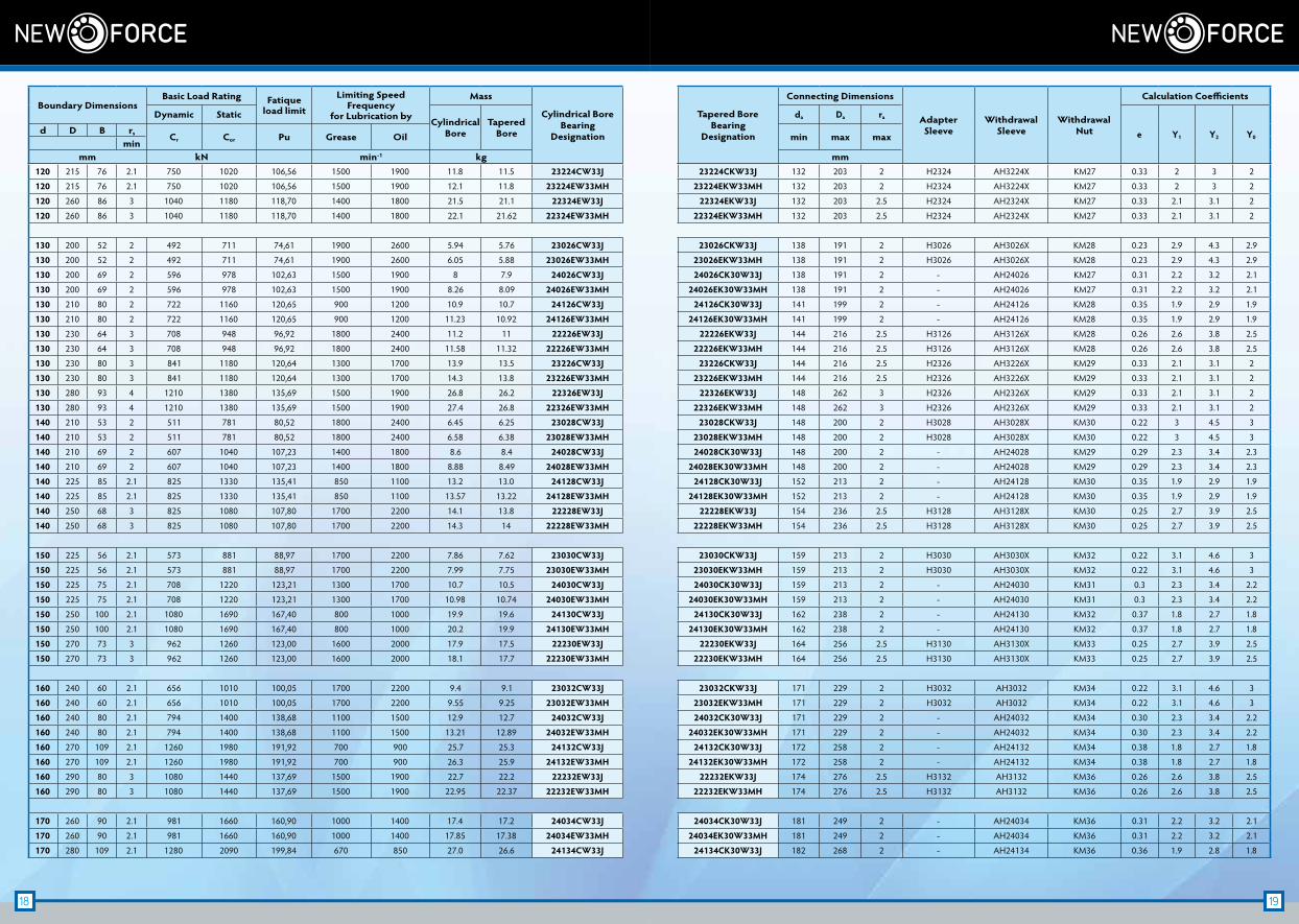
Boundary DimensionsBasic Load Rating Fatique
load limit
Limiting Speed Frequency
for Lubrication by
Mass
Cylindrical BoreBearing
Designation
Tapered BoreBearing
Designation
Connecting Dimensions
AdapterSleeve
WithdrawalSleeve
WithdrawalNut
Calculation Coefficients
Dynamic StaticCylindrical
BoreTapered
Bore
da Da ra
e Y1 Y2 Y0d D B rs Cr Cor Pu Grease Oil min max max
minmm kN min-1 kg mm
18 19
120 215 76 2.1 750 1020 106,56 1500 1900 11.8 11.5 23224CW33J 23224CKW33J 132 203 2 H2324 AH3224X KM27 0.33 2 3 2
120 215 76 2.1 750 1020 106,56 1500 1900 12.1 11.8 23224EW33MH 23224EKW33MH 132 203 2 H2324 AH3224X KM27 0.33 2 3 2
120 260 86 3 1040 1180 118,70 1400 1800 21.5 21.1 22324EW33J 22324EKW33J 132 203 2.5 H2324 AH2324X KM27 0.33 2.1 3.1 2
120 260 86 3 1040 1180 118,70 1400 1800 22.1 21.62 22324EW33MH 22324EKW33MH 132 203 2.5 H2324 AH2324X KM27 0.33 2.1 3.1 2
130 200 52 2 492 711 74,61 1900 2600 5.94 5.76 23026CW33J 23026CKW33J 138 191 2 H3026 AH3026X KM28 0.23 2.9 4.3 2.9
130 200 52 2 492 711 74,61 1900 2600 6.05 5.88 23026EW33MH 23026EKW33MH 138 191 2 H3026 AH3026X KM28 0.23 2.9 4.3 2.9
130 200 69 2 596 978 102,63 1500 1900 8 7.9 24026CW33J 24026CK30W33J 138 191 2 - AH24026 KM27 0.31 2.2 3.2 2.1
130 200 69 2 596 978 102,63 1500 1900 8.26 8.09 24026EW33MH 24026EK30W33MH 138 191 2 - AH24026 KM27 0.31 2.2 3.2 2.1
130 210 80 2 722 1160 120,65 900 1200 10.9 10.7 24126CW33J 24126CK30W33J 141 199 2 - AH24126 KM28 0.35 1.9 2.9 1.9
130 210 80 2 722 1160 120,65 900 1200 11.23 10.92 24126EW33MH 24126EK30W33MH 141 199 2 - AH24126 KM28 0.35 1.9 2.9 1.9
130 230 64 3 708 948 96,92 1800 2400 11.2 11 22226EW33J 22226EKW33J 144 216 2.5 H3126 AH3126X KM28 0.26 2.6 3.8 2.5
130 230 64 3 708 948 96,92 1800 2400 11.58 11.32 22226EW33MH 22226EKW33MH 144 216 2.5 H3126 AH3126X KM28 0.26 2.6 3.8 2.5
130 230 80 3 841 1180 120,64 1300 1700 13.9 13.5 23226CW33J 23226CKW33J 144 216 2.5 H2326 AH3226X KM29 0.33 2.1 3.1 2
130 230 80 3 841 1180 120,64 1300 1700 14.3 13.8 23226EW33MH 23226EKW33MH 144 216 2.5 H2326 AH3226X KM29 0.33 2.1 3.1 2
130 280 93 4 1210 1380 135,69 1500 1900 26.8 26.2 22326EW33J 22326EKW33J 148 262 3 H2326 AH2326X KM29 0.33 2.1 3.1 2
130 280 93 4 1210 1380 135,69 1500 1900 27.4 26.8 22326EW33MH 22326EKW33MH 148 262 3 H2326 AH2326X KM29 0.33 2.1 3.1 2
140 210 53 2 511 781 80,52 1800 2400 6.45 6.25 23028CW33J 23028CKW33J 148 200 2 H3028 AH3028X KM30 0.22 3 4.5 3
140 210 53 2 511 781 80,52 1800 2400 6.58 6.38 23028EW33MH 23028EKW33MH 148 200 2 H3028 AH3028X KM30 0.22 3 4.5 3
140 210 69 2 607 1040 107,23 1400 1800 8.6 8.4 24028CW33J 24028CK30W33J 148 200 2 - AH24028 KM29 0.29 2.3 3.4 2.3
140 210 69 2 607 1040 107,23 1400 1800 8.88 8.49 24028EW33MH 24028EK30W33MH 148 200 2 - AH24028 KM29 0.29 2.3 3.4 2.3
140 225 85 2.1 825 1330 135,41 850 1100 13.2 13.0 24128CW33J 24128CK30W33J 152 213 2 - AH24128 KM30 0.35 1.9 2.9 1.9
140 225 85 2.1 825 1330 135,41 850 1100 13.57 13.22 24128EW33MH 24128EK30W33MH 152 213 2 - AH24128 KM30 0.35 1.9 2.9 1.9
140 250 68 3 825 1080 107,80 1700 2200 14.1 13.8 22228EW33J 22228EKW33J 154 236 2.5 H3128 AH3128X KM30 0.25 2.7 3.9 2.5
140 250 68 3 825 1080 107,80 1700 2200 14.3 14 22228EW33MH 22228EKW33MH 154 236 2.5 H3128 AH3128X KM30 0.25 2.7 3.9 2.5
150 225 56 2.1 573 881 88,97 1700 2200 7.86 7.62 23030CW33J 23030CKW33J 159 213 2 H3030 AH3030X KM32 0.22 3.1 4.6 3
150 225 56 2.1 573 881 88,97 1700 2200 7.99 7.75 23030EW33MH 23030EKW33MH 159 213 2 H3030 AH3030X KM32 0.22 3.1 4.6 3
150 225 75 2.1 708 1220 123,21 1300 1700 10.7 10.5 24030CW33J 24030CK30W33J 159 213 2 - AH24030 KM31 0.3 2.3 3.4 2.2
150 225 75 2.1 708 1220 123,21 1300 1700 10.98 10.74 24030EW33MH 24030EK30W33MH 159 213 2 - AH24030 KM31 0.3 2.3 3.4 2.2
150 250 100 2.1 1080 1690 167,40 800 1000 19.9 19.6 24130CW33J 24130CK30W33J 162 238 2 - AH24130 KM32 0.37 1.8 2.7 1.8
150 250 100 2.1 1080 1690 167,40 800 1000 20.2 19.9 24130EW33MH 24130EK30W33MH 162 238 2 - AH24130 KM32 0.37 1.8 2.7 1.8
150 270 73 3 962 1260 123,00 1600 2000 17.9 17.5 22230EW33J 22230EKW33J 164 256 2.5 H3130 AH3130X KM33 0.25 2.7 3.9 2.5
150 270 73 3 962 1260 123,00 1600 2000 18.1 17.7 22230EW33MH 22230EKW33MH 164 256 2.5 H3130 AH3130X KM33 0.25 2.7 3.9 2.5
160 240 60 2.1 656 1010 100,05 1700 2200 9.4 9.1 23032CW33J 23032CKW33J 171 229 2 H3032 AH3032 KM34 0.22 3.1 4.6 3
160 240 60 2.1 656 1010 100,05 1700 2200 9.55 9.25 23032EW33MH 23032EKW33MH 171 229 2 H3032 AH3032 KM34 0.22 3.1 4.6 3
160 240 80 2.1 794 1400 138,68 1100 1500 12.9 12.7 24032CW33J 24032CK30W33J 171 229 2 - AH24032 KM34 0.30 2.3 3.4 2.2
160 240 80 2.1 794 1400 138,68 1100 1500 13.21 12.89 24032EW33MH 24032EK30W33MH 171 229 2 - AH24032 KM34 0.30 2.3 3.4 2.2
160 270 109 2.1 1260 1980 191,92 700 900 25.7 25.3 24132CW33J 24132CK30W33J 172 258 2 - AH24132 KM34 0.38 1.8 2.7 1.8
160 270 109 2.1 1260 1980 191,92 700 900 26.3 25.9 24132EW33MH 24132EK30W33MH 172 258 2 - AH24132 KM34 0.38 1.8 2.7 1.8
160 290 80 3 1080 1440 137,69 1500 1900 22.7 22.2 22232EW33J 22232EKW33J 174 276 2.5 H3132 AH3132 KM36 0.26 2.6 3.8 2.5
160 290 80 3 1080 1440 137,69 1500 1900 22.95 22.37 22232EW33MH 22232EKW33MH 174 276 2.5 H3132 AH3132 KM36 0.26 2.6 3.8 2.5
170 260 90 2.1 981 1660 160,90 1000 1400 17.4 17.2 24034CW33J 24034CK30W33J 181 249 2 - AH24034 KM36 0.31 2.2 3.2 2.1
170 260 90 2.1 981 1660 160,90 1000 1400 17.85 17.38 24034EW33MH 24034EK30W33MH 181 249 2 - AH24034 KM36 0.31 2.2 3.2 2.1
170 280 109 2.1 1280 2090 199,84 670 850 27.0 26.6 24134CW33J 24134CK30W33J 182 268 2 - AH24134 KM36 0.36 1.9 2.8 1.8
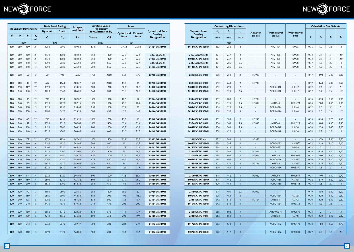
Boundary DimensionsBasic Load Rating Fatique
load limit
Limiting Speed Frequency
for Lubrication by
Mass
Cylindrical BoreBearing
Designation
Tapered BoreBearing
Designation
Connecting Dimensions
AdapterSleeve
WithdrawalSleeve
WithdrawalNut
Calculation Coefficients
Dynamic StaticCylindrical
BoreTapered
Bore
da Da ra
e Y1 Y2 Y0d D B rs Cr Cor Pu Grease Oil min max max
minmm kN min-1 kg mm
20 21
170 280 109 2.1 1280 2090 199,84 670 850 27.64 26.82 24134EW33MH 24134EK30W33MH 182 268 2 - AH24134 KM36 0.36 1.9 2.8 1.8
180 280 100 2.1 1170 1980 188,08 950 1300 22.9 22.6 24036CW33J 24036CK30W33J 191 269 2 - AH24036 KM38 0.32 2.1 3.1 2.0
180 280 100 2.1 1170 1980 188,08 950 1300 23.4 22.8 24036EW33MH 24036EK30W33MH 191 269 2 - AH24036 KM38 0.32 2.1 3.1 2.0
180 300 118 3 1390 2080 225,08 700 850 32.9 32.4 24136CW33J 24136CK30W33J 194 286 2.5 - AH24136 KM38 0.37 1.8 2.7 1.8
180 300 118 3 1390 2080 225,08 700 850 33.3 32.7 24136EW33MH 24136EK30W33MH 194 286 2.5 - AH24136 KM38 0.37 1.8 2.7 1.8
190 260 52 2 551 966 92,37 1700 2200 8,05 7,79 23938EW33MH 23938EKW33MH 200 250 2 H3938 - - 0,17 3,90 5,80 3,80
200 280 80 2,1 692 1160 108,79 1600 2000 11,3 11 23940EW33MH 23940EKW33MH 212 268 2 H3940 - - 0,19 3,60 5,40 3,50
200 310 109 2.1 1390 2370 218,26 900 1200 30.8 30.3 24040EW33MH 24040EK30W33MH 212 298 2 - AOH24040 HM42 0.32 2.1 3.1 2.1
200 340 140 3 1920 3160 286,06 560 700 53.4 52.6 24140EW33MH 24140EK30W33MH 214 326 2.5 - AOH24140 HM42 0.39 1.9 2.6 1.7
220 300 80 2,1 730 1330 109,87 1500 1900 12,3 12 23944EW33MH 23944EKW33MH 232 288 2 H3944 - - 0,16 4,20 6,30 4,00
220 340 90 3 1320 2090 187,15 1100 1500 29,6 28,7 23044EW33MH 23044EKW33MH 234 326 2,5 H3044 AH3044 HML47T 0,24 2,00 4,30 2,80
220 340 118 3 1650 2830 253,41 850 1100 39.7 39 24044EW33MH 24044EK30W33MH 234 326 2.5 - AOH24044 HM46 0.32 2.3 3.1 2.1
220 370 150 4 2200 3690 325,29 500 630 67.1 66.1 24144EW33MH 24144EK30W33MH 238 352 3 - AOH24144 HM46 0.38 1.8 2.6 1.7
240 320 60 2,1 750 1450 115,51 1300 1700 13,3 13 23948EW33MH 23948EKW33MH 252 308 2 H3948 - - 0,15 4,50 6,70 4,50
240 360 92 3 1390 2310 202,61 1000 1400 32,4 31,4 23048EW33MH 23048EKW33MH 254 346 2,5 H3048 AH3048 HML52T 0,23 3,00 4,50 2,90
240 360 118 3 1690 3060 268,39 800 1000 42,8 42,1 24048EW33MH 24048EK30W33MH 254 346 2,5 - AOH24048 HM50 0,30 2,30 3,40 2,20
240 400 160 4 2510 4260 366,48 480 600 82.5 81.3 24148EW33MH 24148EK30W33MH 258 422 3 - AOH24148 HM50 0.38 1.8 2.7 1.8
260 360 75 2,1 1070 1930 167,62 1100 1500 22,9 22,2 23952EW33MH 239EKW33MH 272 348 2 H3952 - - 0,18 3,70 5,50 3,70
260 400 140 4 2190 4020 342,66 700 900 65 63,9 24052EW33MH 24052EK30W33MH 278 385 3 - AOH24052 HM54T 0,32 2,10 3,10 2,10
260 440 180 4 3100 5320 445,53 430 530 115 113 24152EW33MH 24152EK30W33MH 278 422 3 - AOH24152 HM54 0.32 2 3.1 2
280 380 75 2,1 1120 2100 179,00 1000 1400 25 24,2 23956EW33MH 23956EKW33MH 292 368 2 H3956 - - 0,16 4,20 6,30 4,00
280 420 106 4 1820 3060 256,26 850 1100 51,5 49,9 23056EW33MH 23056EKW33MH 298 402 3 H3056 AH3056 HML60T 0,22 3,00 4,50 3,00
280 420 140 4 2240 4280 358,43 670 850 69,7 68,6 24056EW33MH 24056EK30W33MH 298 402 3 - AOH24056 HM52T 0,30 2,20 3,30 2,20
280 460 146 5 2650 4370 359,92 750 950 95 91 23156EW33MH 23156EKW33MH 322 478 4 H3156 AH3156 HM62T 0,29 2,30 3,30 2,20
280 460 180 5 3220 5630 463,70 400 500 121 119 24156EW33MH 24156EK30W33MH 300 440 4 - AOH24156 HM3160 0.37 1.8 2.7 1.8
300 460 118 4 2220 3720 303,94 800 1000 71,5 69,4 23060EW33MH 23060EKW33MH 318 442 3 H3060 AH3060 HML64T 0,23 3,00 4,40 2,90
300 460 160 4 2800 5230 427,32 600 750 97,7 96,2 24060EW33MH 24060EK30W33MH 318 442 3 - AOH24060 HM62T 0,32 2,10 3,20 2,10
300 500 200 5 3830 6790 546,31 360 450 163 160 24160EW33MH 24160EK30W33MH 320 480 4 - AOH24160 HM3164 0.37 1.8 2.7 1.8
320 420 90 3 1500 2690 221,55 950 1300 38,3 37 23960EW33MH 23960EKW33MH 314 406 2,5 H3960 - - 0,19 3,60 5,40 3,50
320 480 160 4 2885 5500 442,52 560 700 103 101,5 24064EW33MH 24064EK30W33MH 338 462 3 - AOH24064 HM66T 0,30 2,20 3,30 2,20
320 540 176 5 3780 6150 484,20 630 800 162 157 23164EW33MH 23164EKW33MH 342 518 4 H3164 AH3164 HM70T 0,30 2,20 3,30 2,20
320 540 218 5 4470 7870 619,61 340 430 208 205 24164EW33MH 24164EK30W33MH 342 518 4 - AOH24164 HM3168 0.38 1.8 2.6 1.7
340 520 180 5 3550 6710 528,28 530 670 141 139 24068EW33MH 24068EKW33MH 358 502 4 - AH24068-H HM3072 0.33 2 3 2
340 580 190 5 4240 6950 536,22 600 750 206 199 23168EW33MH 23168EKW33MH 362 558 4 - AH3168 HM74T 0,30 2,20 3,30 2,20
360 600 243 5 5360 9970 759,47 300 380 284 279 24172EW33MH 24172EK30W33MH 382 578 4 - AOH24172 HM3176 0,38 1,80 2,60 1,70
380 560 180 5 3690 7420 568,80 480 600 154 152 24076EW33MH 24076EK30W33MH 398 542 4 - AOH24076 HM3080 0.29 2.3 3.5 2.3
Boundary DimensionsBasic Load Rating Fatique
load limit
Limiting Speed Frequency
for Lubrication by
Mass
Cylindrical BoreBearing
Designation
Tapered BoreBearing
Designation
Connecting Dimensions
AdapterSleeve
WithdrawalSleeve
WithdrawalNut
Calculation Coefficients
Dynamic StaticCylindrical
BoreTapered
Bore
da Da ra
e Y1 Y2 Y0d D B rs Cr Cor Pu Grease Oil min max max
minmm kN min-1 kg mm
22 23
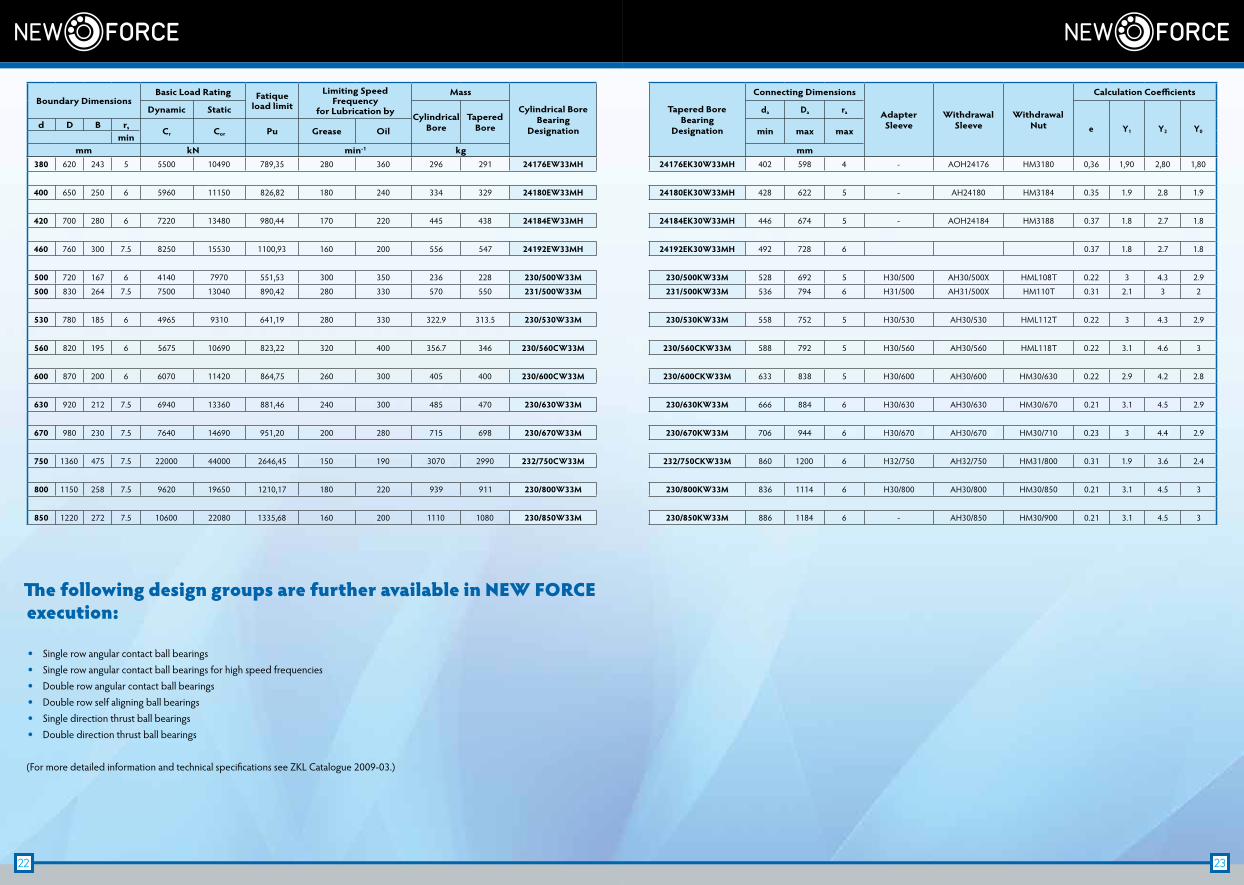
380 620 243 5 5500 10490 789,35 280 360 296 291 24176EW33MH 24176EK30W33MH 402 598 4 - AOH24176 HM3180 0,36 1,90 2,80 1,80
400 650 250 6 5960 11150 826,82 180 240 334 329 24180EW33MH 24180EK30W33MH 428 622 5 - AH24180 HM3184 0.35 1.9 2.8 1.9
420 700 280 6 7220 13480 980,44 170 220 445 438 24184EW33MH 24184EK30W33MH 446 674 5 - AOH24184 HM3188 0.37 1.8 2.7 1.8
460 760 300 7.5 8250 15530 1100,93 160 200 556 547 24192EW33MH 24192EK30W33MH 492 728 6 0.37 1.8 2.7 1.8
500 720 167 6 4140 7970 551,53 300 350 236 228 230/500W33M 230/500KW33M 528 692 5 H30/500 AH30/500X HML108T 0.22 3 4.3 2.9
500 830 264 7.5 7500 13040 890,42 280 330 570 550 231/500W33M 231/500KW33M 536 794 6 H31/500 AH31/500X HM110T 0.31 2.1 3 2
530 780 185 6 4965 9310 641,19 280 330 322.9 313.5 230/530W33M 230/530KW33M 558 752 5 H30/530 AH30/530 HML112T 0.22 3 4.3 2.9
560 820 195 6 5675 10690 823,22 320 400 356.7 346 230/560CW33M 230/560CKW33M 588 792 5 H30/560 AH30/560 HML118T 0.22 3.1 4.6 3
600 870 200 6 6070 11420 864,75 260 300 405 400 230/600CW33M 230/600CKW33M 633 838 5 H30/600 AH30/600 HM30/630 0.22 2.9 4.2 2.8
630 920 212 7.5 6940 13360 881,46 240 300 485 470 230/630W33M 230/630KW33M 666 884 6 H30/630 AH30/630 HM30/670 0.21 3.1 4.5 2.9
670 980 230 7.5 7640 14690 951,20 200 280 715 698 230/670W33M 230/670KW33M 706 944 6 H30/670 AH30/670 HM30/710 0.23 3 4.4 2.9
750 1360 475 7.5 22000 44000 2646,45 150 190 3070 2990 232/750CW33M 232/750CKW33M 860 1200 6 H32/750 AH32/750 HM31/800 0.31 1.9 3.6 2.4
800 1150 258 7.5 9620 19650 1210,17 180 220 939 911 230/800W33M 230/800KW33M 836 1114 6 H30/800 AH30/800 HM30/850 0.21 3.1 4.5 3
850 1220 272 7.5 10600 22080 1335,68 160 200 1110 1080 230/850W33M 230/850KW33M 886 1184 6 - AH30/850 HM30/900 0.21 3.1 4.5 3
Boundary DimensionsBasic Load Rating Fatique
load limit
Limiting Speed Frequency
for Lubrication by
Mass
Cylindrical BoreBearing
Designation
Tapered BoreBearing
Designation
Connecting Dimensions
AdapterSleeve
WithdrawalSleeve
WithdrawalNut
Calculation Coefficients
Dynamic StaticCylindrical
BoreTapered
Bore
da Da ra
e Y1 Y2 Y0d D B rs Cr Cor Pu Grease Oil min max max
minmm kN min-1 kg mm
The following design groups are further available in NEW FORCE execution:
• Single row angular contact ball bearings • Single row angular contact ball bearings for high speed frequencies • Double row angular contact ball bearings • Double row self aligning ball bearings • Single direction thrust ball bearings • Double direction thrust ball bearings
(For more detailed information and technical specifications see ZKL Catalogue 2009-03.)