Embed Size (px)
Citation preview
Understanding Bandwidth Profiles in MEF 6.2 Service Definitions June 2015
MEF 2015021 Page 1 of 19
© The Metro Ethernet Forum 2015. Any reproduction of this document, or any portion thereof, shall contain the following statement: "Reproduced with permission of the Metro Ethernet Forum." No user of this document is authorized to modify any of the information contained herein.
Understanding Bandwidth Profiles in MEF 6.2 Service Definitions
June 2015

Understanding Bandwidth Profiles in MEF 6.2 Service Definitions June 2015
MEF 2015021 Page 2 of 19
Table of Contents
1 Abstract ................................................................................................................................................. 3 2 Background ........................................................................................................................................... 3
2.1 MEF 6.1 Bandwidth Profiles ........................................................................................................ 3 2.2 MEF 10.3 Bandwidth Profiles ...................................................................................................... 4 2.3 MEF 6.2 Bandwidth Profiles ........................................................................................................ 5 2.4 Revised System for Service Frame Classification......................................................................... 6
3 Explaining MEF 6.2 Bandwidth Profiles ................................................................................................ 7 3.1 Single-Flow Processing, Ignoring Token Sharing ......................................................................... 8 3.2 Multi-Flow Processing with Token Sharing ................................................................................. 8 3.3 New Terminology and Service Attributes .................................................................................. 12 3.4 The Impact of Discontinuing Per-UNI and Per-EVC Bandwidth Profiles ................................... 12 3.5 New Opportunities for Sharing Bandwidth ............................................................................... 13
4 Using MEF 6.2 Bandwidth Profiles ...................................................................................................... 14 4.1 Using Ingress Bandwidth Profiles .............................................................................................. 14 4.2 Using Egress Bandwidth Profiles ............................................................................................... 15 4.3 EEC ID and CoS ID ...................................................................................................................... 16
5 Summary ............................................................................................................................................. 17 6 Appendix: New Terminology............................................................................................................... 17 7 Appendix: New EVC Service Attributes ............................................................................................... 17 8 Glossary ............................................................................................................................................... 18 9 References .......................................................................................................................................... 19 10 Acknowledgements............................................................................................................................. 19
Table of Figures
Figure 1: MEF 10.2 Bandwidth Profile Algorithm Visualized as Conceptual Machine ......................................... 3 Figure 2: Three Levels of Bandwidth Profiles ...................................................................................................... 4 Figure 3: MEF 10.3 Bandwidth Profile Algorithm Visualized as Conceptual Machine ........................................ 4 Figure 4: The Purposes of MEF 6.2 Service Frame Classification ........................................................................ 6 Figure 5: The Purpose of CoS Identification ........................................................................................................ 7 Figure 6: The Purpose of EEC Identification ........................................................................................................ 7 Figure 7: Single-Flow Processing, Ignoring Token Sharing .................................................................................. 8 Figure 8: Independent Processing (per MEF 10.2) .............................................................................................. 9 Figure 9: New Paths For Token Sharing .............................................................................................................. 9 Figure 10: New Rate Limiters ............................................................................................................................ 10 Figure 11: Bandwidth Profile with CF0=0 .......................................................................................................... 10 Figure 12: Bandwidth Profile with CF0=1 ......................................................................................................... 11 Figure 13: MEF 6.1 Per-UNI, Per-EVC and Per-CoS ID Bandwidth Profiles ....................................................... 12 Figure 14: MEF 6.2 Bandwidth Profiles Applied per-UNI, per EVC and per-CoS ID in EVC ............................... 12 Figure 15: MEF 6.1 Per-UNI Bandwidth Profile ................................................................................................. 13 Figure 16: MEF 6.2 Per-CoS ID Ingress Bandwidth Profiles ............................................................................... 13 Figure 17: Ingress Bandwidth Profile Processing .............................................................................................. 14 Figure 18: Example Use Case for Egress Bandwidth Profile with EVPLs ........................................................... 15 Figure 19: Example Use Case for Egress Bandwidth Profile with E-LAN ........................................................... 15 Figure 20: Egress Bandwidth Profile Processing ............................................................................................... 16 Figure 21: CoS ID and EEC ID Assignment .......................................................................................................... 16

Understanding Bandwidth Profiles in MEF 6.2 Service Definitions June 2015
MEF 2015021 Page 3 of 19
1 Abstract Bandwidth profiles used in MEF 6.2, Ethernet Services Definitions – Phase 3, have significantly changed compared to those used in MEF 6.1, Ethernet Services Definitions – Phase 2. The following items highlight some significant changes in MEF 6.2:
• The bandwidth profile algorithm is generalized to support more than one flow with token sharing (prioritized bandwidth sharing) among flows.
• Per-UNI and per-EVC bandwidth profiles are no longer used.1 • At egress, per-CoS ID bandwidth profiles are replaced by per-EEC ID bandwidth profiles.2
This paper explains MEF 6.2 bandwidth profiles in relation to MEF 6.1 bandwidth profiles. It discusses backward compatibility, explains expanded capabilities, and offers some insight into using them.
Note: MEF 6.2 supersedes and replaces MEF 6.1.
Readers are assumed to be familiar with MEF 10.2 bandwidth profiles used in MEF 6.1 services.
2 Background
2.1 MEF 6.1 Bandwidth Profiles MEF 6.1 services use the six bandwidth profiles defined in MEF 10.2:
Each bandwidth profile is defined by six parameters (CIR, CBS, EIR, EBS, CF, and CM) that, together with the MEF 10.2 bandwidth profile algorithm, define bandwidth profile processing for a single unidirectional flow of service frames at a UNI.
Conceptually, the MEF 10.2 bandwidth profile algorithm can be visualized as a user-configurable machine that processes a single flow of service frames. The machine (algorithm) is configured using four control dials (CIR, CBS, EIR, and EBS) and two switches (CM, CF) that are set to specific values (the bandwidth profile) as specified in the SLA. The bandwidth profile algorithm (machine) declares each service frame in the flow to be compliant or non-compliant relative to the bandwidth profile (machine control settings). The level of compliance is expressed as one of three colors:
• Green (CIR-conformant) – Service frames are in-profile with respect to service performance objectives and are forwarded.
1 [R6] and [R8] in MEF 6.2 explicitly disallows per-UNI and per-EVC bandwidth profiles. 2 Here, EEC refers to Egress Equivalence Class, a new definition for specifying egress service frame classification (similar to CoS).
Ingress Egress Per-UNI ingress bandwidth profile Per-UNI egress bandwidth profile Per-EVC ingress bandwidth profile Per-EVC egress bandwidth profile
Per-CoS ID ingress bandwidth profile Per-CoS ID egress bandwidth profile
Figure 1: MEF 10.2 Bandwidth Profile Algorithm Visualized as Conceptual Machine
FlowBandwidth ProfileProcessing Machine
CIR CBS EBSEIR CF CM
Bandwidth Profile = all control settings
Discard
Forward
Understanding Bandwidth Profiles in MEF 6.2 Service Definitions June 2015
MEF 2015021 Page 4 of 19
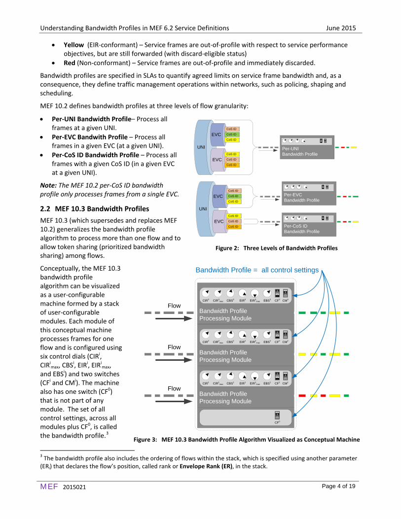
• Yellow (EIR-conformant) – Service frames are out-of-profile with respect to service performance objectives, but are still forwarded (with discard-eligible status)
• Red (Non-conformant) – Service frames are out-of-profile and immediately discarded.
Bandwidth profiles are specified in SLAs to quantify agreed limits on service frame bandwidth and, as a consequence, they define traffic management operations within networks, such as policing, shaping and scheduling.
MEF 10.2 defines bandwidth profiles at three levels of flow granularity:
• Per-UNI Bandwidth Profile– Process all frames at a given UNI.
• Per-EVC Bandwith Profile – Process all frames in a given EVC (at a given UNI).
• Per-CoS ID Bandwidth Profile – Process all frames with a given CoS ID (in a given EVC at a given UNI).
Note: The MEF 10.2 per-CoS ID bandwidth profile only processes frames from a single EVC.
2.2 MEF 10.3 Bandwidth Profiles MEF 10.3 (which supersedes and replaces MEF 10.2) generalizes the bandwidth profile algorithm to process more than one flow and to allow token sharing (prioritized bandwidth sharing) among flows.
Conceptually, the MEF 10.3 bandwidth profile algorithm can be visualized as a user-configurable machine formed by a stack of user-configurable modules. Each module of this conceptual machine processes frames for one flow and is configured using six control dials (CIRi, CIRi
max, CBSi, EIRi, EIRimax,
and EBSi) and two switches (CFi and CMi). The machine also has one switch (CF0) that is not part of any module. The set of all control settings, across all modules plus CF0, is called the bandwidth profile.3
3 The bandwidth profile also includes the ordering of flows within the stack, which is specified using another parameter (ERi) that declares the flow’s position, called rank or Envelope Rank (ER), in the stack.
Figure 2: Three Levels of Bandwidth Profiles
Figure 3: MEF 10.3 Bandwidth Profile Algorithm Visualized as Conceptual Machine
UNI
EVC
EVC
CoS ID
CoS ID
CoS ID
CoS ID
CoS ID
CoS ID
UNI
EVC
EVC
CoS ID
CoS ID
CoS ID
CoS ID
CoS ID
CoS ID Per-CoS IDBandwidth Profile
Per-EVCBandwidth Profile
Per-UNIBandwidth Profile
Bandwidth ProfileProcessing Module
CIR3 CIR3max EIR3 EIR3
maxCBS3 CF3EBS3 CM3
Flow
Bandwidth ProfileProcessing Module
CIR2 CIR2max EIR2 EIR2
maxCBS2 CF2EBS2 CM2
Flow
Bandwidth ProfileProcessing Module
CIR1 CIR1max EIR1 EIR1
maxCBS1 CF1EBS1 CM1
Flow
Bandwidth Profile = all control settings
CF0

Understanding Bandwidth Profiles in MEF 6.2 Service Definitions June 2015
MEF 2015021 Page 5 of 19
Note: Bandwidth profile parameters are indexed with superscripts. Do not confuse indexing with power notation. For example, CIR3 denotes CIR for the third bandwidth profile flow, not CIR cubed.
Token sharing (prioritized bandwidth sharing) occurs between modules within this machine (as described later in this paper).
Using this generalized algorithm, MEF 10.3 defines generalized (multi-flow) bandwidth profiles for five of the six bandwidth profiles defined in MEF 10.2:
MEF 10.2 Bandwidth Profiles MEF 10.3 Bandwidth Profiles 1. Per-UNI ingress bandwidth profile Per-UNI ingress bandwidth profile 2. Per-EVC ingress bandwidth profile Per-EVC ingress bandwidth profile 3. Per-CoS ID ingress bandwidth profile Per-CoS ID ingress bandwidth profile 4. Per-UNI egress bandwidth profile Per-UNI egress bandwidth profile 5. Per-EVC egress bandwidth profile Per-EVC egress bandwidth profile
The sixth MEF 10.2 bandwidth profile (the per-CoS ID egress bandwidth profile) is replaced in MEF 10.3 by a new bandwidth profile: the per-EEC ID egress bandwidth profile.
MEF 10.2 Bandwidth Profiles MEF 10.3 Bandwidth Profiles 6. Per-CoS ID egress bandwidth profile Per-EEC ID egress bandwidth profile
Here, EEC refers to Egress Equivalence Class, a new definition for specifying egress service frame classification, introduced in MEF 10.3. EEC ID is similar to CoS ID, but is independent of CoS ID, as described later in this paper.
Overall, the whole system of MEF 10.3 bandwidth profiles is backwardly compatible with the whole system of MEF 10.2 bandwidth profiles (any MEF 10.2 bandwidth profile can be translated to an equivalent MEF 10.3 bandwidth profile). However, MEF 6.2 does not adopt the entire system of MEF 10.3 bandwidth profiles, as explained in the next section.
2.3 MEF 6.2 Bandwidth Profiles MEF 6.2 defines EVC services using only two out of the six MEF 10.3 bandwidth profiles4 – the two most granular ones:
• Per-CoS ID ingress bandwidth profile • Per-EEC ID egress bandwidth profile
The aforementioned differences in MEF 6.2 bandwidth profiles requires further explanation to understand how to relate them to MEF 6.1 bandwidth profiles. The MEF 6.2 algorithm is more general (it can support multiple flows with token sharing among flows), however per-UNI and per-EVC bandwidth profiles (used with MEF 6.1 service definitions) are not used with MEF 6.2 service definitions. Additionally, the per-CoS ID egress bandwidth profile is replaced by the per-EEC ID egress bandwidth profile.
4 [R6] and [R8] in MEF 6.2 explicitly disallows per-UNI and per-EVC bandwidth profile attributes (even though both are defined in MEF 10.3).
Understanding Bandwidth Profiles in MEF 6.2 Service Definitions June 2015
MEF 2015021 Page 6 of 19
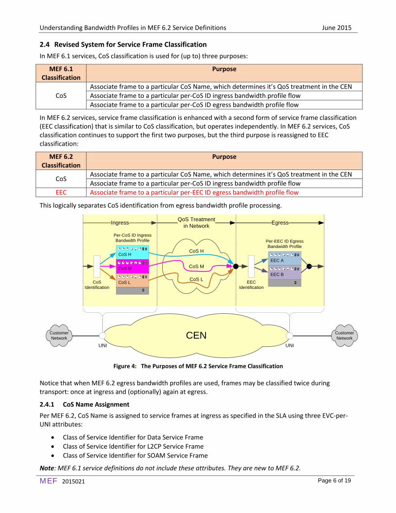
2.4 Revised System for Service Frame Classification In MEF 6.1 services, CoS classification is used for (up to) three purposes:
MEF 6.1 Classification
Purpose
CoS Associate frame to a particular CoS Name, which determines it’s QoS treatment in the CEN Associate frame to a particular per-CoS ID ingress bandwidth profile flow Associate frame to a particular per-CoS ID egress bandwidth profile flow
In MEF 6.2 services, service frame classification is enhanced with a second form of service frame classification (EEC classification) that is similar to CoS classification, but operates independently. In MEF 6.2 services, CoS classification continues to support the first two purposes, but the third purpose is reassigned to EEC classification:
MEF 6.2 Classification
Purpose
CoS Associate frame to a particular CoS Name, which determines it’s QoS treatment in the CEN Associate frame to a particular per-CoS ID ingress bandwidth profile flow
EEC Associate frame to a particular per-EEC ID egress bandwidth profile flow
This logically separates CoS identification from egress bandwidth profile processing.
Figure 4: The Purposes of MEF 6.2 Service Frame Classification
Notice that when MEF 6.2 egress bandwidth profiles are used, frames may be classified twice during transport: once at ingress and (optionally) again at egress.
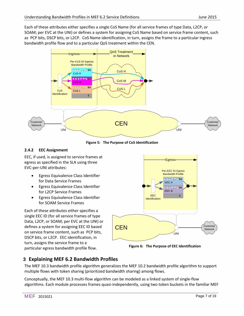
2.4.1 CoS Name Assignment Per MEF 6.2, CoS Name is assigned to service frames at ingress as specified in the SLA using three EVC-per-UNI attributes:
• Class of Service Identifier for Data Service Frame • Class of Service Identifier for L2CP Service Frame • Class of Service Identifier for SOAM Service Frame
Note: MEF 6.1 service definitions do not include these attributes. They are new to MEF 6.2.
CustomerNetwork
CustomerNetwork
CoS H
CoS M
CoS L
Per-CoS ID Ingress Bandwidth Profile Per-EEC ID Egress
Bandwidth Profile
CoSIdentification
EECIdentification
CustomerNetwork
UNI
CustomerNetwork
EEC A
EEC B
Ingress EgressQoS Treatment in Network
CEN
CoS H
CoS M
CoS L
UNI
Understanding Bandwidth Profiles in MEF 6.2 Service Definitions June 2015
MEF 2015021 Page 7 of 19
Each of these attributes either specifies a single CoS Name (for all service frames of type Data, L2CP, or SOAM; per EVC at the UNI) or defines a system for assigning CoS Name based on service frame content, such as PCP bits, DSCP bits, or L2CP. CoS Name identification, in turn, assigns the frame to a particular ingress bandwidth profile flow and to a particular QoS treatment within the CEN.
Figure 5: The Purpose of CoS Identification
2.4.2 EEC Assignment EEC, if used, is assigned to service frames at egress as specified in the SLA using three EVC-per-UNI attributes:
• Egress Equivalence Class Identifier for Data Service Frames
• Egress Equivalence Class Identifier for L2CP Service Frames
• Egress Equivalence Class Identifier for SOAM Service Frames
Each of these attributes either specifies a single EEC ID (for all service frames of type Data, L2CP, or SOAM; per EVC at the UNI) or defines a system for assigning EEC ID based on service frame content, such as PCP bits, DSCP bits, or L2CP. EEC identification, in turn, assigns the service frame to a particular egress bandwidth profile flow.
3 Explaining MEF 6.2 Bandwidth Profiles The MEF 10.3 bandwidth profile algorithm generalizes the MEF 10.2 bandwidth profile algorithm to support multiple flows with token sharing (prioritized bandwidth sharing) among flows.
Conceptually, the MEF 10.3 multi-flow algorithm can be modeled as a linked system of single-flow algorithms. Each module processes frames quasi-independently, using two token buckets in the familiar MEF
CustomerNetwork
CustomerNetwork
CoS H
CoS M
CoS L
Per-CoS ID Ingress Bandwidth Profile
CoSIdentification
CustomerNetwork
UNI
CustomerNetwork
Ingress QoS Treatment in Network
CEN
CoS H
CoS M
CoS L
UNI
Figure 6: The Purpose of EEC Identification
CustomerNetwork
Per-EEC ID Egress Bandwidth Profile
EECIdentification
UNI
CustomerNetwork
EEC A
EEC B
Egress
CEN

Understanding Bandwidth Profiles in MEF 6.2 Service Definitions June 2015
MEF 2015021 Page 8 of 19
10.2 fashion. However, the overall algorithm includes new mechanisms that allow unused tokens to pass between modules (token sharing), so frame processing by each module is not truly independent.
The algorithm will be explained in steps, first ignoring token sharing, then adding and explaining token sharing mechanisms one-by-one.
3.1 Single-Flow Processing, Ignoring Token Sharing Each flowi (i=1,…N) is assigned to a dedicated module that processes the flow using two token buckets (one green and one yellow) using familiar rules adopted from the MEF 10.2 bandwidth profile algorithm:
• To be assigned color green, the green bucket must contain one token for each byte in the frame. If green is assigned to the frame, that number of tokens is drained from the green token bucket.
• To be assigned color yellow, the yellow bucket must contain one token for each byte in the frame. If yellow is assigned to the frame, that number of tokens is drained from the yellow token bucket.
• Each frame is assigned one color: green (if possible), otherwise yellow (if possible), otherwise red. • If parameter CMi is set to color-aware, frames that are pre-colored yellow bypass green bucket
processing and go directly to yellow bucket processing. • Both buckets have a size (maximum token capacity) that is set by CBSi (green bucket) or EBSi (yellow
bucket). • Both buckets have a nominal token fill rate that is set by CIRi/8 (green bucket) or EIRi/8 (yellow
bucket). • If parameter CFi is set to 1, tokens overflowing from the green bucket go into the yellow bucket.
All of this processing matches MEF 10.2 bandwidth profile processing. If the MEF 10.3 bandwidth profile includes only one flow, it is defined using only six parameters (CIRi, CBSi, EIRi, EBSi, CFi, and CMi) and becomes equivalent to the MEF 10.2 bandwidth profile.
3.2 Multi-Flow Processing with Token Sharing The MEF 10.3 bandwidth profile algorithm adopts all of the aforementioned per-flow processing from the MEF 10.2 bandwidth profile algorithm, and then enhances it with new mechanisms to support token sharing between flows as explained incrementally in the following figures.
Figure 7: Single-Flow Processing, Ignoring Token Sharing
forward
Yellow Bucket
Test
frame green
forward
Enough Green
Tokens? yellow
Yes
No Yes
NoIf CMi=color-aware and frame is yellow, bypass
green bucket.
Enough Yellow
Tokens? reddrop
flow in flow out
Bandwidth ProfileProcessing Module
Bandwidth ProfileProcessing Module
Bandwidth ProfileProcessing Module
EBSi
CFi
0
1
CBSi
CIRi
EIRi
flow in flow out
flow in flow out

Understanding Bandwidth Profiles in MEF 6.2 Service Definitions June 2015
MEF 2015021 Page 9 of 19
As a starting point, assume that each module processes frames independently, per the MEF 10.2 bandwidth profile algorithm. No tokens are shared between modules.
Now add pathways to allow tokens (previously lost due to bucket overflow) to flow downward to the next module below.
Yellow bucket overflow now goes to the next yellow bucket. Green bucket overflow when CFi=0 goes to the next green bucket.
Figure 8: Independent Processing (per MEF 10.2)
Figure 9: New Paths For Token Sharing
flow in flow out
flow in flow out
flow in flow out
Bandwidth ProfileProcessing Module
Bandwidth ProfileProcessing Module
Bandwidth ProfileProcessing Module
flow in flow out
CIR1
EIR1
CF1 1
0CBS1
EBS1
flow in flow out
CIR2
EIR2
1
0CBS2
EBS2
flow in flow out
CIR3
EIR3
1
0CBS3
EBS3
CF2
CF3
Token Bucket Overflow
flow in flow out
flow in flow out
flow in flow out
Bandwidth ProfileProcessing Module
Bandwidth ProfileProcessing Module
Bandwidth ProfileProcessing Module
flow in flow out
CIR1
EIR1
CF1 1
0CBS1
EBS1
flow in flow out
CIR2
EIR2
1
0CBS2
EBS2
flow in flow out
CIR3
EIR3
1
0CBS3
EBS3
CF2
CF3
Token Bucket Overflow

Understanding Bandwidth Profiles in MEF 6.2 Service Definitions June 2015
MEF 2015021 Page 10 of 19
Now add a new rate limiting mechanism (shown graphically as a funnel) above each token bucket. Each of these mechanisms has one control setting, CIRi
max (green bucket) or EIRi
max (yellow bucket), which limits the rate of token flow into the token bucket.
The rate limiting mechanism does not store tokens or discard tokens. It functions like a gatekeeper that admits all tokens to the token bucket unless tokens arrive at a rate greater than the limit set (CIRi
max or EIRimax). When tokens
arrive faster than the limit (CIRimax or EIRi
max), the rate limiter fills the token bucket at the limiting rate (CIRimax
or EIRimax) and passes remaining tokens onward, to be combined with tokens from token bucket overflow.
Notice that all modules, except the bottom one, preserve unused tokens (representing available bandwidth) by passing them downward for possible use by lower ranking flows.
3.2.1 CF0=0 If the system-wide coupling flag (CF0) is set to zero (CF0=0), the algorithm operates as previously described.
Figure 10: New Rate Limiters
Figure 11: Bandwidth Profile with CF0=0
flow in flow out
flow in flow out
flow in flow out
Bandwidth ProfileProcessing Module
Bandwidth ProfileProcessing Module
Bandwidth ProfileProcessing Module
flow in flow out
(Rate Limiter)EIR1
max(Rate Limiter)CIR1
max
CIR1
EIR1
CF1 1
0CBS1
EBS1
flow in flow out
(Rate Limiter)EIR2
max(Rate Limiter)CIR2
max
CIR2
EIR2
1
0CBS2
EBS2
flow in flow out
(Rate Limiter)EIR3
max(Rate Limiter)CIR3
max
CIR3
EIR3
1
0CBS3
EBS3
CF2
CF3
Fill Rate Excess
Token Bucket Overflow
flow in flow out
flow in flow out
flow in flow out
Bandwidth ProfileProcessing Module
Bandwidth ProfileProcessing Module
Bandwidth ProfileProcessing Module
CF00
flow in flow out
(Rate Limiter)EIR1
max(Rate Limiter)CIR1
max
CIR1
EIR1
CF1 1
0CBS1
EBS1
flow in flow out
(Rate Limiter)EIR2
max(Rate Limiter)CIR2
max
CIR2
EIR2
1
0CBS2
EBS2
flow in flow out
(Rate Limiter)EIR3
max(Rate Limiter)CIR3
max
CIR3
EIR3
1
0CBS3
EBS3
CF2
CF3
Fill Rate Excess
Token Bucket Overflow

Understanding Bandwidth Profiles in MEF 6.2 Service Definitions June 2015
MEF 2015021 Page 11 of 19
3.2.2 CF0=1 Otherwise (if CF0=1), there are two changes: (1) tokens overflowing from the bottom green bucket flow upward to the top yellow bucket and (2) all of the other coupling flags are set to zero5.
Notice that CF0=1 forces all the other CF flags to have the value 0, defining the path for token sharing. Unused tokens pass through the chain of green buckets (top to bottom), then through the chain of yellow buckets (top to bottom).
The key feature differentiating the MEF 10.3 bandwidth profile algorithm (used by MEF 6.2 services) from the MEF 10.2 bandwidth profile algorithm (used by MEF 6.1 services) is the ability to govern more than one flow with bandwidth shared among flows in a flexible and explicitly-defined manner.
The system for sharing bandwidth is flexible, but is not without structure:
• Tokens from a green bucket cannot overflow to higher ranking green bucket • Tokens from a yellow bucket cannot overflow to higher ranking yellow bucket • Tokens from a yellow bucket cannot overflow to green bucket
Unused tokens (bandwidth) are only shared from higher-ranking flows to lower-ranking flows or with color demotion from green to yellow.
This implies that flows should be ordered (ranked) such that unused bandwidth is downwardly shareable. For example, higher CoS flows are typically ranked higher than lower CoS flows because unused bandwidth from a higher CoS flow can usually be reallocated to a lower CoS flow without increasing service performance commitment.
Note: All flows processed by a MEF 10.3 bandwidth profile must be of the same type. For example, a MEF 6.2 bandwidth profile can be assigned to process multiple per-CoS ingress flows or multiple per-EEC egress flows, but not a combination of per-CoS ingress flows and per-EEC egress flows.
5 Per [R150] in MEF 10.3: If CF0 = 1 for an envelope, then CFi MUST equal 0 for all bandwidth profile flows mapped to the envelope.
Figure 12: Bandwidth Profile with CF0=1
flow in flow out
flow in flow out
flow in flow out
Bandwidth ProfileProcessing Module
Bandwidth ProfileProcessing Module
Bandwidth ProfileProcessing Module
CF0 1
flow in flow out
(Rate Limiter)EIR1
max(Rate Limiter)CIR1
max
CIR1
EIR1
CF1
0CBS1
EBS1
flow in flow out
(Rate Limiter)EIR2
max(Rate Limiter)CIR2
max
CIR2
EIR2
0CBS2
EBS2
flow in flow out
(Rate Limiter)EIR3
max(Rate Limiter)CIR3
max
CIR3
EIR3
0CBS3
EBS3
CF2
CF3
Fill Rate Excess
Token Bucket Overflow

Understanding Bandwidth Profiles in MEF 6.2 Service Definitions June 2015
MEF 2015021 Page 12 of 19
3.3 New Terminology and Service Attributes MEF 6.2 bandwidth profiles are defined using new terminology (bandwidth profile flow, envelope, and rank) and new service attributes (Envelopes and Token Share, Ingress Bandwidth Profile per-CoS ID, and Egress Bandwidth Profile per-EEC ID). Refer to the appendix of this paper for more details.
3.4 The Impact of Discontinuing Per-UNI and Per-EVC Bandwidth Profiles Going from MEF 6.1 services to MEF 6.2 services, per-UNI and per-EVC bandwidth profile attributes are no longer used. MEF 6.2 bandwidth profiles must be per-CoS ID (at ingress) or per-EEC ID (at egress). However, there is no loss in functionality because a single MEF 6.2 bandwidth profile can process any number of flows, including all of the per-CoS ID flows (or per-EEC ID flows) at a UNI or EVC if desired.
A MEF 6.1 per-UNI (or per-EVC) bandwidth profile processes all frames at the UNI (or EVC) with no awareness of CoS ID. If the UNI (or EVC) supports multiple CoS ID flows, frames are processed indiscriminately (without awareness of CoS ID).
A MEF 6.2 bandwidth profile can similarly process all frames at a UNI (or EVC). However, frame processing is no longer indiscriminate. The MEF 6.2 bandwidth profile explicitly defines how bandwidth is allocated per-CoS ID flow (or EEC ID flow) and how bandwidth is shared among flows.
Figure 13: MEF 6.1 Per-UNI, Per-EVC and Per-CoS ID Bandwidth Profiles
Figure 14: MEF 6.2 Bandwidth Profiles Applied per-UNI, per EVC and per-CoS ID in EVC
UNI
EVC
EVC
CoS ID
CoS ID
CoS ID
CoS ID
CoS ID
CoS ID
UNI
EVC
EVC
CoS ID
CoS ID
CoS ID
CoS ID
CoS ID
CoS ID Per-CoS IDBandwidth Profile
Per-EVCBandwidth Profile
Per-UNIBandwidth Profile
UNI
EVC
EVC
CoS ID
CoS ID
CoS ID
CoS ID
UNI
EVC
EVC
CoS ID
CoS ID
CoS ID
CoS ID
Multi-Flowper-CoS IDBandwidthProfile for UNI
Multi-Flowper-CoS IDBandwidthProfile for EVC
Single-Flow per-CoS ID BandwidthProfile for CoS ID in EVC

Understanding Bandwidth Profiles in MEF 6.2 Service Definitions June 2015
MEF 2015021 Page 13 of 19
One might argue that MEF 6.2 bandwidth profiles are not fully backwardly compatible with MEF 6.1 bandwidth profiles because they do not permit “indiscriminate” per-UNI and per-EVC frame processing. However, MEF 6.2 bandwidth profiles include better (more flexible and less arbitrary) frame processing. So any loss of backward compatibility is actually beneficial.
3.5 New Opportunities for Sharing Bandwidth The benefit of MEF 6.2 bandwidth profiles, compared to MEF 6.1 bandwidth profiles, is that they enable multiple flows to share a common pool of bandwidth in a flexible, prioritized, and well-defined fashion.
MEF 6.1 per-UNI and per-EVC bandwidth profiles allow multiple per-CoS ID flows. However, they lack any ability to prioritize how bandwidth is shared among those per-CoS flows. Such indiscriminate bandwidth sharing is not very useful to the subscriber because all traffic gets equal/random access to the available bandwidth, regardless of CoS ID.
MEF 6.2 bandwidth profiles, in contrast, can include any selection of per-CoS ID flows (or per-EEC ID flows) from the set of all per-CoS ID flows (or per-EEC ID flows) present at the UNI. 6 The following example illustrates a UNI served by two per-CoS ID ingress bandwidth profiles:
• A multi-flow bandwidth profile that governs three per-CoS ID flows from two different EVCs • A single-flow bandwidth profile that governs one per-CoS ID flow
All bandwidth associated with the single-flow bandwidth profile is dedicated to the single flow and cannot be shared with other flows. Any bandwidth that is unused by that flow is wasted. In contrast, the multi-flow bandwidth profile can allocate bandwidth to each of three flows and additionally allow unused bandwidth from higher ranking flows to “trickle down” to lower ranking flows. This benefits subscribers because it enables them to use all of the subscribed bandwidth.
6A bandwidth profile cannot include both per-CoS ID flows and per-EEC ID flows.
Figure 15: MEF 6.1 Per-UNI Bandwidth Profile
Figure 16: MEF 6.2 Per-CoS ID Ingress Bandwidth Profiles
UNI
EVC
EVC
CoS ID
CoS ID
CoS ID
CoS ID
CoS ID
CoS ID
Per-UNIBandwidth Profile
Processing Module
Single-Flow Bandwidth Profile
Processing Module
Processing Module
UNI
EVC
EVC
CoS ID
CoS ID
CoS ID
CoS ID
Processing Module
Processing Module
Multi-Flow Bandwidth Profile
Single-Flow Bandwidth Profile
Processing Module
FlowFlow

Understanding Bandwidth Profiles in MEF 6.2 Service Definitions June 2015
MEF 2015021 Page 14 of 19
4 Using MEF 6.2 Bandwidth Profiles Conceptually, at a high level, any bandwidth profile (MEF 6.1 or MEF 6.2) establishes two things:
• An agreed algorithm for processing frames at a particular external interface in the network7 into three categories (green, yellow, and red)
• Limits on the quantity of green traffic and yellow traffic that will be supported for the service
Bandwidth profiles limit the quantity of ingress and egress traffic so that the service provider allocates sufficient network resources to ensure that green traffic is supported with agreed performance assurances specified in an SLA.
4.1 Using Ingress Bandwidth Profiles At ingress, each service frame maps to a CoS Name which, in turn, assigns the frame to a particular ingress bandwidth profile flow and to particular QoS treatment within the CEN.
Figure 17: Ingress Bandwidth Profile Processing
The service provider typically uses the ingress bandwidth profile to condition traffic at ingress. Traffic conditioning includes policing which limits ingress traffic to agreed levels (per-CoS) and marking which assigns color (green or yellow) to those frames that are admitted.
The subscriber transmits service frames into the network (EVC) with full understanding of associated service delivery assurances as specified in the SLA. Green service frames are in-profile and provided with service performance objectives, while yellow frames are out of profile and not subject to any service performance objectives.
7 In EVC services, bandwidth profiles apply at UNIs. In OVC services they can apply at UNIs and/or at ENNIs.
CustomerNetwork
CustomerNetwork
CoS H
CoS M
CoS L
Per-CoS ID Ingress Bandwidth Profile
CoSIdentification
CustomerNetwork
UNI
CustomerNetwork
Ingress QoS Treatment in Network
CEN
CoS H
CoS M
CoS L
UNI

Understanding Bandwidth Profiles in MEF 6.2 Service Definitions June 2015
MEF 2015021 Page 15 of 19
4.2 Using Egress Bandwidth Profiles Egress bandwidth profiles are not allowed, nor required, for EPL services because there is no service multiplexing and thus no opportunity for traffic contention. However, they can be used with other MEF services as illustrated in the following examples.
Figure 18: Example Use Case for Egress Bandwidth Profile with EVPLs
In this example, EVPLs from three branch offices are service multiplexed to one UNI at the company headquarters. Ingress bandwidth profiles applied at the branch offices already limit egress traffic aggregating to the company headquarters. However, the worst-case aggregate total may be more than the headquarters UNI can support or may cost more than the subscriber wishes to pay. This example illustrates the utility of egress bandwidth profiles. In this example, the egress bandwidth profile limits egress traffic at the headquarters UNI to the amount that the organization ordered (an amount that is less than the sum of all bandwidth that the three branch offices could send to the headquarters).
Egress bandwidth profiles serve this same purpose in multipoint service applications, such as in the following.
Figure 19: Example Use Case for Egress Bandwidth Profile with E-LAN
Without the egress bandwidth profile, the headquarters UNI would have to support the worst-case scenario where traffic from all of the branch office UNIs (limited only by the ingress bandwidth profiles) is sent to the headquarters UNI.
UNI Branch Office
Headquarters
CEN
EVPL
EVPL UNI
UNI
EVPL
Single-flowper-CoS ID ingress bandwidth profiles
Multi-flowper-EEC egress bandwidth profile
Direction of Traffic Flow
Branch Office
Branch Office
(Traffic flow is bidirectional, but only one direction is considered)
UNI
UNI Branch Office
Headquarters
CENUNI
UNIPer-CoS ingress bandwidth profiles
Per-EEC egress bandwidth profile
Direction of Traffic Flow
Branch Office
Branch Office
(Traffic flow is bidirectional, but only one direction is considered)
UNI E-LAN

Understanding Bandwidth Profiles in MEF 6.2 Service Definitions June 2015
MEF 2015021 Page 16 of 19
4.3 EEC ID and CoS ID
At egress, each service frame that maps to an EEC ID is assigned to a particular egress bandwidth profile flow. Egress bandwidth profile processing then determines the service frame’s fate (whether it is discarded or delivered).
Figure 20: Egress Bandwidth Profile Processing
The following example illustrates CoS ID assignment and EEC ID assignment for a single service frame traveling from ingress UNI to egress UNI(s) in a multipoint service application.
Figure 21: CoS ID and EEC ID Assignment
CoS ID assignment occurs at ingress. EEC ID assignment occurs at egress. Both may be different for different UNIs. Both can be assigned per-EVC (at the UNI) or based on service frame content (PCP or DSCP values) at the UNI. CoS ID assignment is independent of EEC ID assignment.
CustomerNetwork
CustomerNetwork
Per-EEC ID Egress Bandwidth Profile
EECIdentification
CustomerNetwork
UNI
CustomerNetwork
EEC A
EEC B
Egress
CENUNI
CustomerNetwork
UNI
CustomerNetwork
CustomerNetwork
CoS IDAssignment
EEC IDAssignment
Ingress
CustomerNetwork
UNI
Customer Frame
Service Frame Transport Egress Customer
Frame
CEN
Service Frame
EEC IDAssignment
UNI
Egress Customer Frame
Service Frame

Understanding Bandwidth Profiles in MEF 6.2 Service Definitions June 2015
MEF 2015021 Page 17 of 19
5 Summary The MEF 6.2 update to EVC service definitions includes significant changes to bandwidth profiles:
• The MEF 10.2 bandwidth profile algorithm is replaced by a more general algorithm, defined in MEF 10.3, which can support multiple flows with an ability to share bandwidth among flows.
• Per-UNI and per-EVC bandwidth profiles (available in MEF 6.1 service definitions) are no longer used. • At egress, the per-CoS ID bandwidth profile is replaced by the per-EEC ID egress bandwidth profile.
This paper has described and explained these changes at a conceptual level. MEF 6.2 and MEF 10.3 [3] provide normative requirements. Appendix C of MEF 10.3 provides informative bandwidth profile examples.
These new bandwidth profile capabilities enable service providers to differentiate their service offerings. Service providers and subscribers also benefit by obtaining more efficient bandwidth utilization through well-defined, flexible and prioritized bandwidth sharing among different flows.
6 Appendix: New Terminology Term Description
Bandwidth Profile Flow
The unidirectional flow of service frames processed by one “module” of the MEF 10.3 bandwidth profile algorithm is called a bandwidth profile flow.
[R137], MEF 10.3: A service frame must be mapped to at most one bandwidth profile flow.
Envelope The collection of bandwidth profile flows processed by a particular MEF 10.3 bandwidth profile is called an envelope.
[R136], MEF 10.3: Each bandwidth profile flow at a UNI must belong to exactly one envelope.
Rank Within an envelope, each bandwidth profile flow is assigned a unique rank between 1 (lowest) and n (highest) that determines the “module” that it is processed by. The flow assigned rank 1 is processed by the bottom “module”.
[R153], MEF 10.3: The value of the rank [assigned to a bandwidth profile flow] must not equal the rank of any of the other bandwidth profile flows [within the same envelope]
7 Appendix: New EVC Service Attributes Attribute
(Attribute Type) Description
Envelopes (per-UNI)
Per MEF 6.2, attribute Envelopes specifies three values for each envelope that includes two or more bandwidth profile flows:
• Envelope ID • CF0 (value of the envelope-wide coupling flag) • n (the number of bandwidth profile flows in the envelope)
[R5], MEF 6.2: [The Envelopes attribute] must consist of only those envelopes with two or more bandwidth profile flows.
The Envelopes attribute does not account for envelopes that have just one bandwidth profile flow because single-flow bandwidth profiles are defined without Envelope ID or the other two values, which are known (CF0=0, n=1).8
8 Per [R142] in MEF 10.3, When one bandwidth profile flow is mapped to an envelope, CF0 must equal 0.

Understanding Bandwidth Profiles in MEF 6.2 Service Definitions June 2015
MEF 2015021 Page 18 of 19
Attribute (Attribute Type)
Description
Token Share (per-UNI)
Per MEF 6.2, attribute Token Share indicates whether or not the UNI is capable of sharing tokens across bandwidth profile flows.
[R2], MEF 6.2: A UNI, with Token Share enabled, must be able to support two or more bandwidth profile flows in at least one envelope.
[R3], MEF 6.2: A UNI with Token Share disabled must have exactly one bandwidth profile flow per envelope.
If Token Share is disabled, the Envelopes per-UNI attribute will be an empty list, per [R5] in MEF 6.2.
Ingress Bandwidth Profile per-CoS ID (EVC-per-UNI)
Per MEF 10.3, attribute Ingress Bandwidth Profile per-CoS ID is assigned one of two values: No or Parameters. If value Parameters is assigned, one of two sets of values must be specified for each CoS in the EVC that is assigned to the bandwidth profile.9 If its envelope is not shared, seven values must be specified:
CoS Name (for flowi), CIRi, CBSi, EIRi, EBSi, CFi, and CMi
Otherwise (if its envelope is shared), eleven values must be specified:
CoS Name (for flowi), CIRi, CIRimax , CBSi, EIRi, EIRi
max, EBSi, CFi, CMi, and ERi, where ERi= <Envelope ID, rank>
Egress Bandwidth Profile per-EEC ID (EVC-per-UNI)
Per MEF 10.3, attribute Egress Bandwidth Profile per EEC ID is assigned one of two values: No or Parameters. If value Parameters is assigned, one of two sets of values must be specified for each EEC in the EVC that is assigned to a bandwidth profile.10 If its envelope is not shared, seven values must be specified:
CoS Name (for flowi), CIRi, CBSi, EIRi, EBSi, CFi, and CMi
Otherwise (if its envelope is shared), eleven values must be specified:
CoS Name (for flowi), CIRi, CIRimax , CBSi, EIRi, EIRi
max, EBSi, CFi, CMi, and ERi, where ERi= <Envelope ID, rank>
8 Glossary Term Description Term Description
Bandwidth Profile
A characterization of the lengths and arrival times for Service Frames at a reference point.
ENNI External Network-to-Network Interface
Bandwidth Profile Flow
A set of Service Frames at a UNI that meet a specific set of criteria. Envelope
A set of n Bandwidth Profile Flows in which each Bandwidth Profile Flow is assigned a unique rank between 1 (lowest) and n (highest).
CBS Committed Burst Size EPL Ethernet Private Line CE Customer Edge EVC Ethernet Virtual Connection CEN Carrier Ethernet Network EVPL Ethernet Virtual Private Line
9 Ingress service frames that are not assigned to a bandwidth profile flow are not subject to a bandwidth profile. 10 Egress service frames that are not assigned to a bandwidth profile flow are not subject to a bandwidth profile.

Understanding Bandwidth Profiles in MEF 6.2 Service Definitions June 2015
MEF 2015021 Page 19 of 19
Term Description Term Description
CF Coupling Flag Ingress Service Frame
A Service Frame sent from the CE into the Service Provider network.
CIR Committed Information Rate L2CP Service Frame
Layer 2 Control Protocol Service Frame
CM Color Mode OAM Operations, Administration, and Management
CoS Class of Service OVC Operator Virtual Connection CoS ID Class of Service Identifier PCP Priority Code Point
CoS Name A parameter used in Performance Metrics that specifies the Class of Service Name for the metric
QoS Quality of Service
Data Service Frame
A Service Frame that is neither a Layer 2 Control Protocol Service Frame nor a SOAM Service Frame.
Service Frame An Ethernet frame transmitted across the UNI in either direction
DSCP Differentiated Services Code Point Service Provider The seller of network services
Egress Service Frame
A Service Frame sent from the Service Provider network to the CE.
SOAM Service OAM
EBS Excess Burst Size SLA Service Level Agreement
EEC Egress Equivalence Class SOAM service frame
A Service Frame that is not an L2CP Service Frame and whose Ethertype = 0x8902.
EEC ID Egress Equivalence Class Identifier Subscriber The buyer of network services EIR Excess Information Rate UNI User-to-Network Interface
E-LAN Service Type
An Ethernet Service Type that is based on a Multipoint-to-Multipoint EVC
9 References [1] MEF 6.2, EVC Ethernet Service Definitions Phase 3, August, 2014. [2] MEF 6.1, Ethernet Services Definitions - Phase 2, April, 2008. [3] MEF 10.2, Ethernet Services Attributes Phase 2, October 2009. [4] MEF 10.3, Ethernet Services Attributes Phase 3, October 2013.
10 AcknowledgementsAuthors and Editors: Jon Kieffer and Ralph Santitoro, Fujitsu Contributors: Bruce Eldridge, CenturyLink; Bruno Giguère, MEF, Yoav Cohen, RAD; Rami Yaron, Telco Systems.