Embed Size (px)
Citation preview
VELOCITY LOGO CMYK COLORS
Mega-Stor® IIStainless Steel, Indirect Water Heaters
INSTALLATION AND OPERATING INSTRUCTIONS
CAUTION1. The heat transfer-medium must be water or other nontoxic fluid having a
toxicity rating or Class of 1, as listed in Clinical Toxicology of Commercial Products, 5th edition.
2. The pressure of the heat transfer medium must be limited to a maximum of 30 PSIG by an approved safety or relief valve.
Velocity Boiler Works, LLCP.O. Box 148183633 I StreetPhiladelphia, PA 19134www.velocityboilerworks.com
5003502
980155 Rev 0 - 5/16

2
1
IMPORTANT INFORMATION - READ CAREFULLYNOTE: The equipment shall be installed in accordance with those installation regulations enforced in the area where the installation is to be made. These regulations shall be carefully followed in all cases. Authorities having jurisdiction shall be consulted before installations are made.
All wiring on indirect water heaters installed in the USA shall be made in accordance with the National Electrical Code and/or local regulations.
All wiring on indirect water heaters installed in Canada shall be made in accordance with the Canadian Electrical Code and/or local regulations.
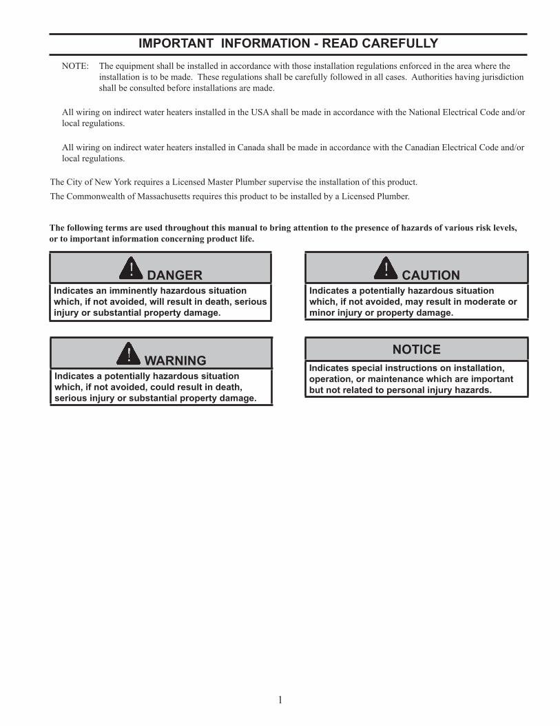
The following terms are used throughout this manual to bring attention to the presence of hazards of various risk levels, or to important information concerning product life.
The City of New York requires a Licensed Master Plumber supervise the installation of this product.The Commonwealth of Massachusetts requires this product to be installed by a Licensed Plumber.
DANGERIndicates an imminently hazardous situation which, if not avoided, will result in death, serious injury or substantial property damage.
CAUTIONIndicates a potentially hazardous situation which, if not avoided, may result in moderate or minor injury or property damage.
WARNINGIndicates a potentially hazardous situation which, if not avoided, could result in death, serious injury or substantial property damage.
NOTICEIndicates special instructions on installation, operation, or maintenance which are important but not related to personal injury hazards.
2
WARNINGScald Hazard. This indirect water heater requires regular maintenance and service to operate safely. Follow the instructions contained in this manual.
Improper installation, adjustment, alteration, service or maintenance can cause property damage, personal injury or loss of life. Read and understand the entire manual before attempting installation, start-up operation, or service. Installation and service must be performed only by an experienced, skilled, and knowledgeable installer or service agency.
Installation is not complete unless a temperature and pressure relief valve is installed into the tapping located on top of the indirect water heater. - See Section V of this manual for details.
Burn Hazard. This indirect water heater contains very hot water under high pressure. Do not unscrew any pipe fittings nor attempt to disconnect any components without positively assuring the water is cool and has no pressure. Always wear protective clothing and equipment when installing, starting up or servicing this product to prevent scald injuries. Do not rely on the pressure or temperature gauges to determine the temperature and pressure of the water heater. Portions of this indirect water heater and connected piping become very hot while operating. Do not touch any components unless they are cool.
Failure to follow all instructions in the proper order can cause personal injury or death. Read all instructions, including all those contained in component manufacturers manuals which are provided before installing, starting up, operating, maintaining or servicing.
All cover plates, enclosures and guards must be in place at all times.
3
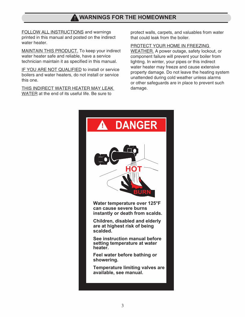
FOLLOW ALL INSTRUCTIONS and warnings printed in this manual and posted on the indirect water heater.
MAINTAIN THIS PRODUCT. To keep your indirect water heater safe and reliable, have a service technician maintain it as specified in this manual.
IF YOU ARE NOT QUALIFIED to install or service boilers and water heaters, do not install or service this one.
THIS INDIRECT WATER HEATER MAY LEAK WATER at the end of its useful life. Be sure to
protect walls, carpets, and valuables from water that could leak from the boiler.
PROTECT YOUR HOME IN FREEZING WEATHER. A power outage, safety lockout, or component failure will prevent your boiler from lighting. In winter, your pipes or this indirect water heater may freeze and cause extensive property damage. Do not leave the heating system unattended during cold weather unless alarms or other safeguards are in place to prevent such damage.
WARNINGS FOR THE HOMEOWNER
83.50
3
158.75
216.50
DANGER
BURN
HOT
!
IN PART OR AS A WHOLE WITHOUT THE WRITTEN PERMISSION OF
Products, 5th Edition.
EXCEPT WHERE SHOWN OTHERWISE.
D
C
B
A
B
C
D
12345678
8 7 6 5 4 3 2 1
PART NUMBER 980014
can cause severe burns
Feel water before bathing or
Danger/Scald Label
available, see manual.
Children, disabled and elderly
CAUTION LABEL
0.10"
limited to a maximum of 30 psi by an
CROWN BOILER COMPANY IS PROHIBITED.
PROPRIETARY AND CONFIDENTIAL
CHANGE CBC TO VBW, CHANGED WORDING OFUNLESS OTHERWISE SPECIFIED:
in Clinical Toxicology of Commercial
heater.
See instruction manual before
0.03"
Temperature limiting valves are
Water temperature over 125°F
THREE PLACE DECIMAL
scalded.
setting temperature at water
THE INFORMATION CONTAINED IN THIS DRAWING IS THE SOLE
are at highest risk of being
showering.
* The boiler water pressure must be
3. LETTERING TO BE BLACK BOLD FACED.
PROPERTY OF CROWN BOILER COMPANY. ANY REPRODUCTION
approved safety or relief valve.
0.005"
MATERIALNoted
DRAWN
ENG APPR.
DATENAME
SIZE
BDWG. NO. REV
JP
- -
10-22-10
Sheet1 of 1
MS-002
DO NOT SCALE DRAWING
B
A Added Part Number JP 10-5-11
BY DATE
B
instantly or death from scalds.
PHILADELPHIA, PA 19134
TWO PLACE DECIMAL
12-17-15
DESCRIPTIONREV
VELOCITY BOILER WORKS
JP
DIMENSIONS ARE IN INCHESTOLERANCES:FRACTIONAL 1/32"ANGULAR: BEND 1°ONE PLACE DECIMAL
* The heat-transfer medium must bewater or other nontoxic fluid having atoxicity rating or Class of 1, as listed
NOTES: 1. MAT'L: ANSI/UL 969 CERTIFIED LABEL SYSTEM. 2. LETTERING BLACK ON WHITE BACKGROUND
CAUTION
4
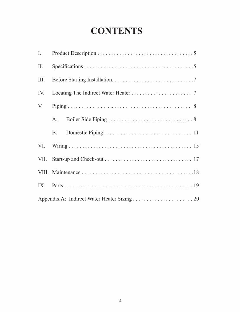
CONTENTS
I. Product Description . . . . . . . . . . . . . . . . . . . . . . . . . . . . . . . . . . . 5
II. Specifications........................................5
III. Before Starting Installation. . . . . . . . . . . . . . . . . . . . . . . . . . . . . . 7
IV. Locating The Indirect Water Heater . . . . . . . . . . . . . . . . . . . . . . 7
V. Piping . . . . . . . . . . . . . . . .. . . . . . . . . . . . . . . . . . . . . . . . . . . . . 8
A. Boiler Side Piping . . . . . . . . . . . . . . . . . . . . . . . . . . . . . . . 8
B. Domestic Piping . . . . . . . . . . . . . . . . . . . . . . . . . . . . . . . . 11
VI. Wiring . . . . . . . . . . . . . . . . . . . . . . . . . . . . . . . . . . . . . . . . . . . . . 15
VII. Start-up and Check-out . . . . . . . . . . . . . . . . . . . . . . . . . . . . . . . . 17
VIII. Maintenance . . . . . . . . . . . . . . . . . . . . . . . . . . . . . . . . . . . . . . . . . 18
IX. Parts . . . . . . . . . . . . . . . . . . . . . . . . . . . . . . . . . . . . . . . . . . . . . . . 19
Appendix A: Indirect Water Heater Sizing . . . . . . . . . . . . . . . . . . . . . . 20
5
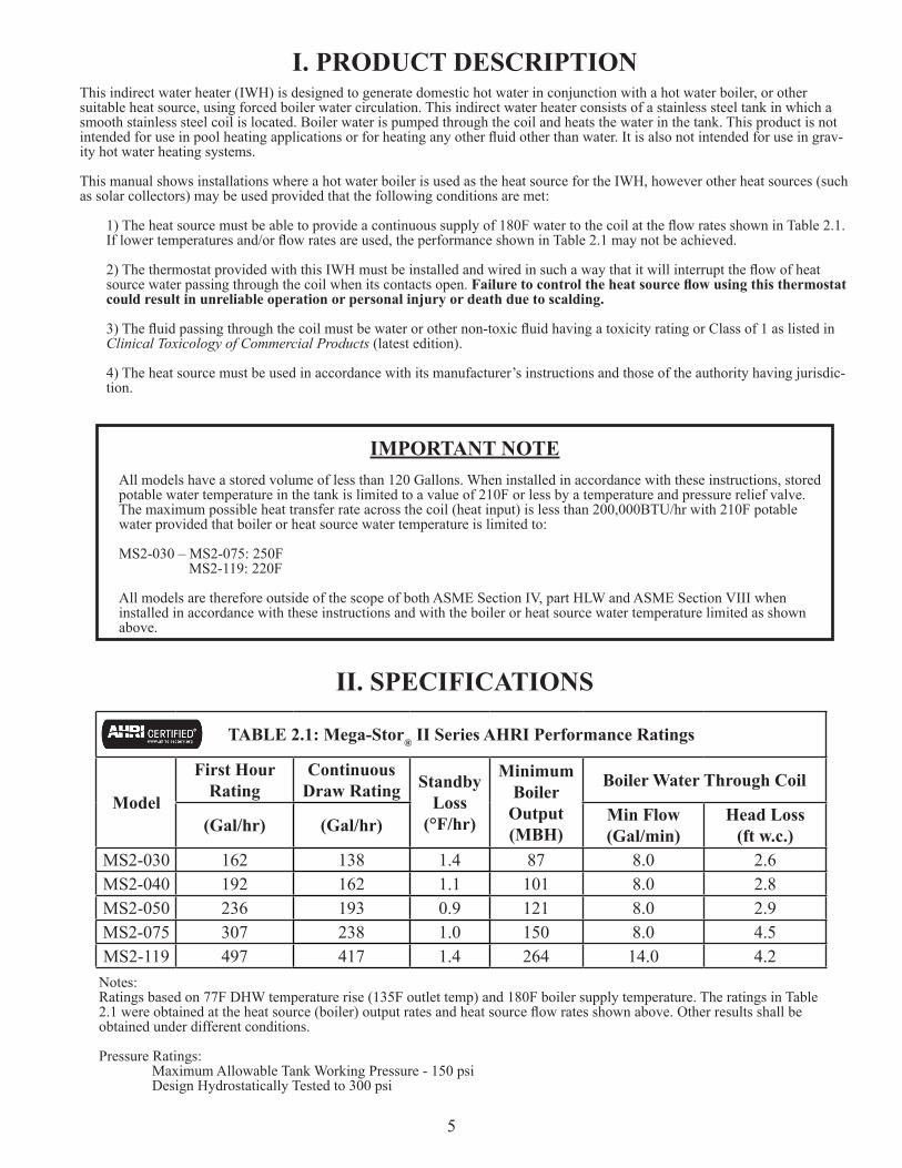
I. PRODUCT DESCRIPTIONThis indirect water heater (IWH) is designed to generate domestic hot water in conjunction with a hot water boiler, or other suitable heat source, using forced boiler water circulation. This indirect water heater consists of a stainless steel tank in which a smooth stainless steel coil is located. Boiler water is pumped through the coil and heats the water in the tank. This product is not intendedforuseinpoolheatingapplicationsorforheatinganyotherfluidotherthanwater.Itisalsonotintendedforuseingrav-ity hot water heating systems.
This manual shows installations where a hot water boiler is used as the heat source for the IWH, however other heat sources (such as solar collectors) may be used provided that the following conditions are met:
1)Theheatsourcemustbeabletoprovideacontinuoussupplyof180FwatertothecoilattheflowratesshowninTable2.1.Iflowertemperaturesand/orflowratesareused,theperformanceshowninTable2.1maynotbeachieved.
2)ThethermostatprovidedwiththisIWHmustbeinstalledandwiredinsuchawaythatitwillinterrupttheflowofheatsource water passing through the coil when its contacts open. Failure to control the heat source flow using this thermostat could result in unreliable operation or personal injury or death due to scalding.
3)Thefluidpassingthroughthecoilmustbewaterorothernon-toxicfluidhavingatoxicityratingorClassof1aslistedinClinical Toxicology of Commercial Products (latest edition).
4) The heat source must be used in accordance with its manufacturer’s instructions and those of the authority having jurisdic-tion.
IMPORTANT NOTEAll models have a stored volume of less than 120 Gallons. When installed in accordance with these instructions, stored potable water temperature in the tank is limited to a value of 210F or less by a temperature and pressure relief valve. The maximum possible heat transfer rate across the coil (heat input) is less than 200,000BTU/hr with 210F potable water provided that boiler or heat source water temperature is limited to:
MS2-030 – MS2-075: 250F MS2-119: 220F
All models are therefore outside of the scope of both ASME Section IV, part HLW and ASME Section VIII when installed in accordance with these instructions and with the boiler or heat source water temperature limited as shown above.
II. SPECIFICATIONS
Notes:Ratings based on 77F DHW temperature rise (135F outlet temp) and 180F boiler supply temperature. The ratings in Table 2.1wereobtainedattheheatsource(boiler)outputratesandheatsourceflowratesshownabove.Otherresultsshallbeobtained under different conditions.
Pressure Ratings: Maximum Allowable Tank Working Pressure - 150 psi Design Hydrostatically Tested to 300 psi
TABLE 2.1: Mega-Stor® II Series AHRI Performance Ratings
Model
First Hour Rating
Continuous Draw Rating Standby
Loss(°F/hr)
MinimumBoiler
Output(MBH)
Boiler Water Through Coil
(Gal/hr) (Gal/hr) Min Flow(Gal/min)
Head Loss(ft w.c.)
MS2-030 162 138 1.4 87 8.0 2.6MS2-040 192 162 1.1 101 8.0 2.8MS2-050 236 193 0.9 121 8.0 2.9MS2-075 307 238 1.0 150 8.0 4.5MS2-119 497 417 1.4 264 14.0 4.2
6
DescriptionModel
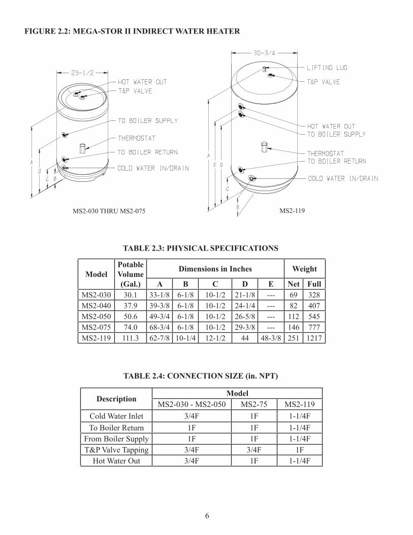
MS2-030 - MS2-050 MS2-75 MS2-119Cold Water Inlet 3/4F 1F 1-1/4FTo Boiler Return 1F 1F 1-1/4F
From Boiler Supply 1F 1F 1-1/4FT&P Valve Tapping 3/4F 3/4F 1F
Hot Water Out 3/4F 1F 1-1/4F
TABLE 2.4: CONNECTION SIZE (in. NPT)
ModelPotable Volume(Gal.)
Dimensions in Inches Weight
A B C D E Net FullMS2-030 30.1 33-1/8 6-1/8 10-1/2 21-1/8 --- 69 328MS2-040 37.9 39-3/8 6-1/8 10-1/2 24-1/4 --- 82 407MS2-050 50.6 49-3/4 6-1/8 10-1/2 26-5/8 --- 112 545MS2-075 74.0 68-3/4 6-1/8 10-1/2 29-3/8 --- 146 777MS2-119 111.3 62-7/8 10-1/4 12-1/2 44 48-3/8 251 1217
TABLE 2.3: PHYSICAL SPECIFICATIONS
FIGURE 2.2: MEGA-STOR II INDIRECT WATER HEATER
MS2-030 THRU MS2-075 MS2-119
7
III. BEFORE STARTING INSTALLATION 1) Be sure that the planned installation is in accordance with all local codes.
2) Be certain the domestic water supply to the indirect water heater (IWH) has physical and chemical characteristics that fall withinthelimitsshownbelow.Wherequestionsexistastothecompositionofthewateronthejob,aqualifiedwater treatment expert should be consulted. 3) Read and understand all installation requirements in this manual. 4) Make sure that both this IWH and the boiler are sized to meet the domestic hot water demand. For basic sizing information see Appendix A.
IV. LOCATING THE INDIRECT WATER HEATER 1)Table2.3showstheweightofeachindirectwaterheater(IWH)filledwithwater.Makesurethatthelocationchosenfor the IWH is capable of supporting it.
2) Locate the IWH in a location where a leak in the tank, the adjacent piping, or an open T&P valve will not damage the surrounding structure. If the surrounding area is highly susceptible to water damage, install the IWH in a pan with a drain.
3)TheIWHmaybelocatedsomedistancefromtheboilerprovidedthezonesystemisdesignedtoprovidetheflowcalledfor in Table 2.1 through the coil. Also, the further the IWH is from the boiler, the longer the response of the boiler will be to a call from the IWH thermostat. If long runs exist between the boiler and IWH it is advisable to insulate the piping.
CAUTIONWater used in this indirect water heater must have characteristics falling within the following limits:PH 6.0 – 8.0Chloride Content – Less than 80PPMMaximum domestic hot water temperature – 150F Water failing to meet these requirements may severely shorten the life of this product due to corrosion. Such corrosion damage is not covered by the warranty.
WARNINGFailure to properly support an indirect water heater could result in property damage, personal injury or death.
WARNINGLike all water heaters, this product may leak water at the end of its useful life. Where water from such leakage could cause property damage, install this indirect water heater on a drain pan that is piped to a suitable drainage point.
8
V. PIPINGA) BOILER SIDE PIPING
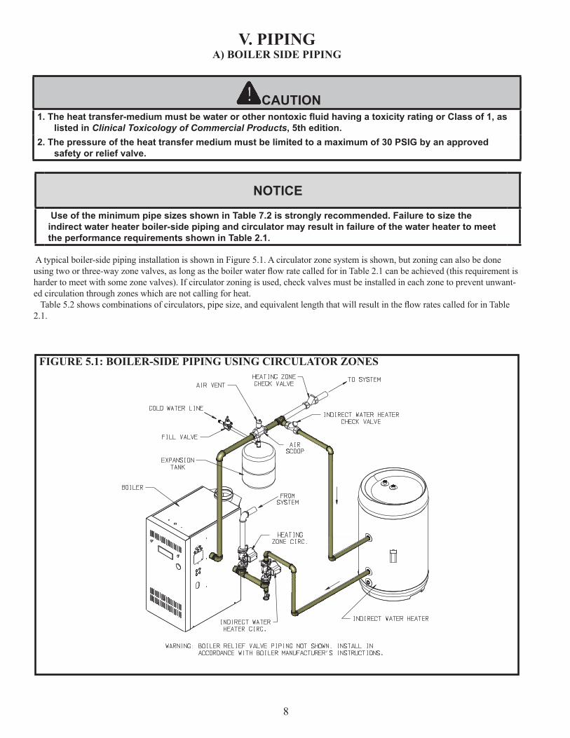
A typical boiler-side piping installation is shown in Figure 5.1. A circulator zone system is shown, but zoning can also be done usingtwoorthree-wayzonevalves,aslongastheboilerwaterflowratecalledforinTable2.1canbeachieved(thisrequirementisharder to meet with some zone valves). If circulator zoning is used, check valves must be installed in each zone to prevent unwant-ed circulation through zones which are not calling for heat. Table5.2showscombinationsofcirculators,pipesize,andequivalentlengththatwillresultintheflowratescalledforinTable2.1.
FIGURE 5.1: BOILER-SIDE PIPING USING CIRCULATOR ZONES
CAUTION1. The heat transfer-medium must be water or other nontoxic fluid having a toxicity rating or Class of 1, as
listed in Clinical Toxicology of Commercial Products, 5th edition.2. The pressure of the heat transfer medium must be limited to a maximum of 30 PSIG by an approved
safety or relief valve.
NOTICE
Use of the minimum pipe sizes shown in Table 7.2 is strongly recommended. Failure to size the indirect water heater boiler-side piping and circulator may result in failure of the water heater to meet the performance requirements shown in Table 2.1.
9
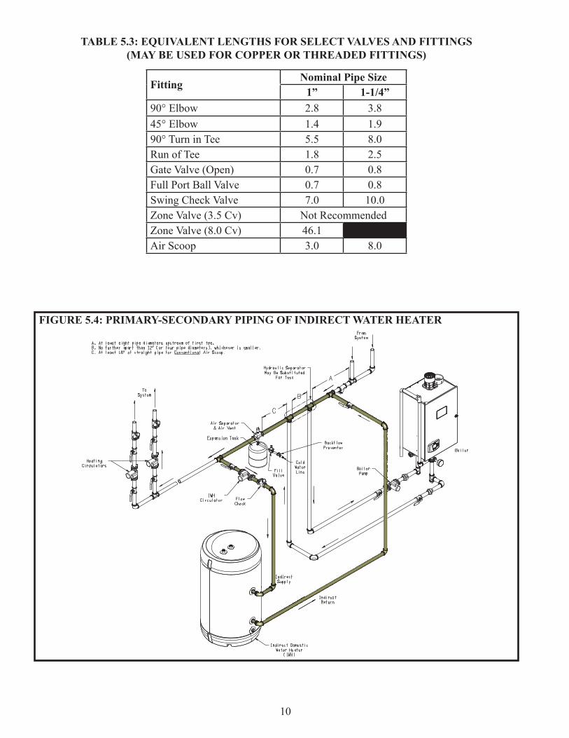
The maximum equivalent length shown in Table 5.2 is that for the indirect water heater loop (IWH loop). The IWH loop piping is shaded in Figure 5.1. To calculate the equivalent length of this loop:
1)Countallfittingsintheplannedboilerloop. 2)UsingTable5.3,findtheequivalentlengthofeachfittingsintheIWHloop.Indoingthis,keepthefollowinginmind: a. In many cases, there will be more than one pipe size in the IWH loop. As long as all piping in the loop exceeds the size shown in Table 5.2, conservative results can be obtained by treating all piping in the loop as though it were of the smallest size. b. The equivalent length of most cast iron boilers can be safely treated as zero. This is often not the case, however, with condensing and water tube boilers. In such cases either use primary-secondary piping (Figure 5.4) or use an alternate method to size the pump and piping. 3)Aftertheequivalentlengthforallfittingshasbeenidentified,totalthemandaddtheresulttothetotallengthofstraight pipe in the loop. This sum is the total equivalent length for the IWH loop and must be less than that shown in Table 5.2 in order to use the circulators shown. 4) If primary-secondary piping is used as shown in Figure 5.4, calculation of equivalent length is exactly the same as shown above, except that IWH loop is the shaded piping in Figure 5.4 (i.e. the IWH loop does not pass through the boiler).
Example: A 40 gallon IWH is to be installed in the IWH loop piping shown in Figure 5.1 (shaded). The cast iron boiler has a negligible pressure drop. The loop consists of the following pipe and fittings:
Qty Size Description3 1-1/4” 90 Elbow1 1-1/4” Turn in Tee1 1-1/4” Run of Tee1 1-1/4” Air scoop1 1” Swing check5 1” Elbows5ft 1-1/4” Straight pipe15ft 1” Straight pipe.
Solution: For simplicity, treat all pipe as though it were 1”. Equivalent length is then calculated as follows:
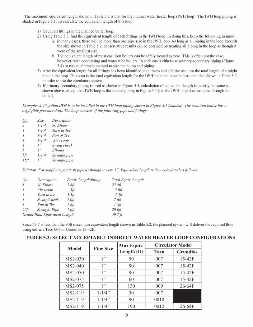
Qty Description Equiv. Length/fitting Total Equiv. Length8 90 Elbow 2.8ft 22.4ft1 Air scoop 3ft 3.0ft1 Turn in tee 5.5ft 5.5ft1 Swing Check 7.0ft 7.0ft1 Run of Tee 1.8ft 1.8ft20ft Straight Pipe 1.0ft 20.0ftGrand Total Equivalent Length: 59.7 ft
Since59.7islessthanthe90ftmaximumequivalentlengthshowninTable5.2,theplannedsystemwilldelivertherequiredflowusing either a Taco 007 or Grundfos 15-42F.
Model Pipe Size Max Equiv. Length (ft)
Circulator ModelTaco Grundfos
MS2-030 1” 90 007 15-42FMS2-040 1” 90 007 15-42FMS2-050 1” 90 007 15-42FMS2-075 1” 60 007 15-42FMS2-075 1” 130 009 26-64FMS2-119 1-1/4” 30 007MS2-119 1-1/4” 90 0010MS2-119 1-1/4” 190 0012 26-64F
TABLE 5.2: SELECT ACCEPTABLE INDIRECT WATER HEATER LOOP CONFIGURATIONS
10
FittingNominal Pipe Size
1” 1-1/4”90° Elbow 2.8 3.845° Elbow 1.4 1.990° Turn in Tee 5.5 8.0Run of Tee 1.8 2.5Gate Valve (Open) 0.7 0.8Full Port Ball Valve 0.7 0.8Swing Check Valve 7.0 10.0Zone Valve (3.5 Cv) Not RecommendedZone Valve (8.0 Cv) 46.1Air Scoop 3.0 8.0
TABLE 5.3: EQUIVALENT LENGTHS FOR SELECT VALVES AND FITTINGS(MAY BE USED FOR COPPER OR THREADED FITTINGS)
FIGURE 5.4: PRIMARY-SECONDARY PIPING OF INDIRECT WATER HEATER
11
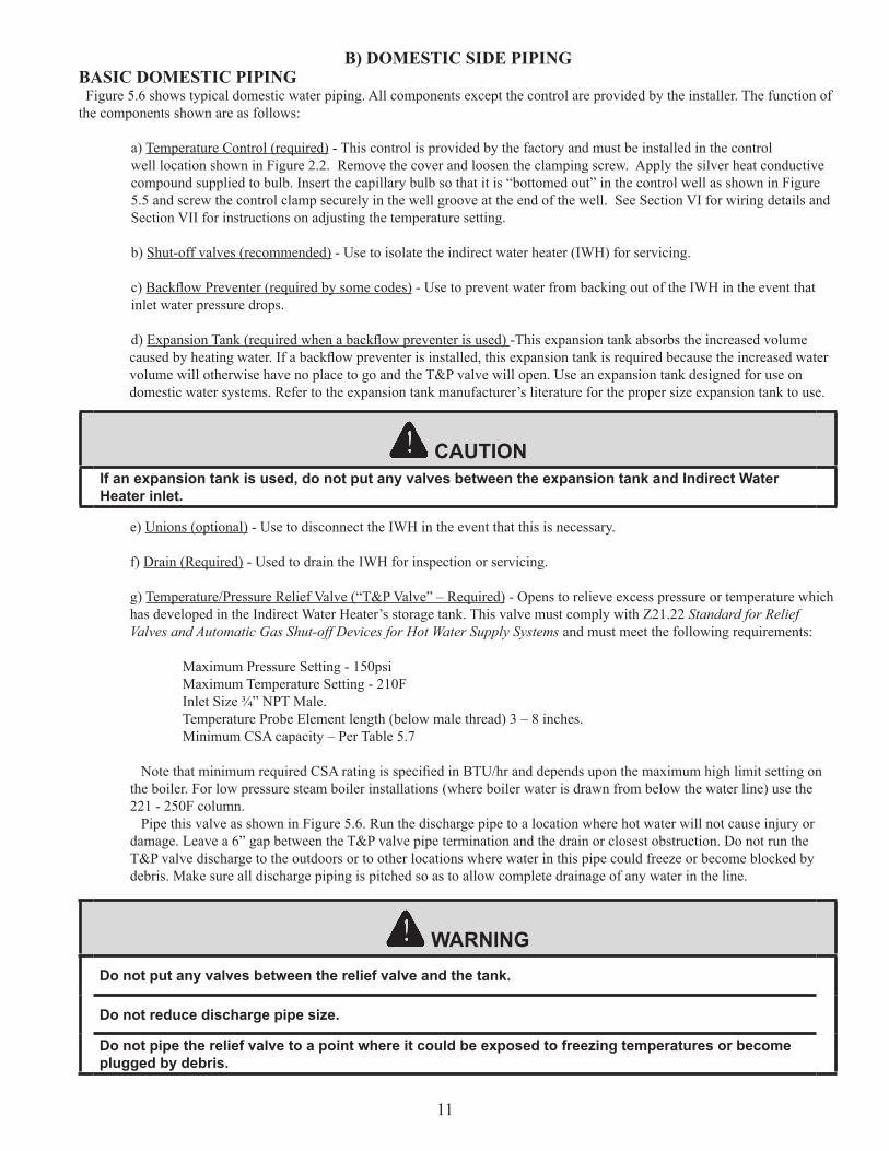
B) DOMESTIC SIDE PIPINGBASIC DOMESTIC PIPING Figure 5.6 shows typical domestic water piping. All components except the control are provided by the installer. The function of the components shown are as follows:
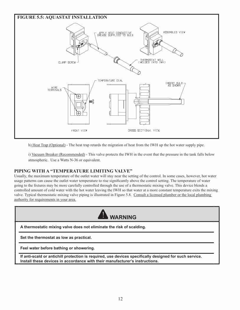
a) Temperature Control (required) - This control is provided by the factory and must be installed in the control well location shown in Figure 2.2. Remove the cover and loosen the clamping screw. Apply the silver heat conductive compound supplied to bulb. Insert the capillary bulb so that it is “bottomed out” in the control well as shown in Figure 5.5 and screw the control clamp securely in the well groove at the end of the well. See Section VI for wiring details and Section VII for instructions on adjusting the temperature setting. b) Shut-off valves (recommended) - Use to isolate the indirect water heater (IWH) for servicing. c) BackflowPreventer(requiredbysomecodes) - Use to prevent water from backing out of the IWH in the event that inlet water pressure drops. d) ExpansionTank(requiredwhenabackflowpreventerisused)-This expansion tank absorbs the increased volumecausedbyheatingwater.Ifabackflowpreventerisinstalled,thisexpansiontankisrequiredbecausetheincreasedwater volume will otherwise have no place to go and the T&P valve will open. Use an expansion tank designed for use on domestic water systems. Refer to the expansion tank manufacturer’s literature for the proper size expansion tank to use.
e) Unions (optional) - Use to disconnect the IWH in the event that this is necessary. f) Drain (Required) - Used to drain the IWH for inspection or servicing. g) Temperature/Pressure Relief Valve (“T&P Valve” – Required) - Opens to relieve excess pressure or temperature which has developed in the Indirect Water Heater’s storage tank. This valve must comply with Z21.22 Standard for Relief Valves and Automatic Gas Shut-off Devices for Hot Water Supply Systems and must meet the following requirements:
Maximum Pressure Setting - 150psi Maximum Temperature Setting - 210F Inlet Size ¾” NPT Male. Temperature Probe Element length (below male thread) 3 – 8 inches. Minimum CSA capacity – Per Table 5.7
NotethatminimumrequiredCSAratingisspecifiedinBTU/hranddependsuponthemaximumhighlimitsettingon the boiler. For low pressure steam boiler installations (where boiler water is drawn from below the water line) use the 221 - 250F column. Pipe this valve as shown in Figure 5.6. Run the discharge pipe to a location where hot water will not cause injury or damage. Leave a 6” gap between the T&P valve pipe termination and the drain or closest obstruction. Do not run the T&P valve discharge to the outdoors or to other locations where water in this pipe could freeze or become blocked by debris. Make sure all discharge piping is pitched so as to allow complete drainage of any water in the line.
CAUTIONIf an expansion tank is used, do not put any valves between the expansion tank and Indirect Water Heater inlet.
WARNINGDo not put any valves between the relief valve and the tank.
Do not reduce discharge pipe size.
Do not pipe the relief valve to a point where it could be exposed to freezing temperatures or become plugged by debris.
12
h) Heat Trap (Optional) - The heat trap retards the migration of heat from the IWH up the hot water supply pipe.
i) Vacuum Breaker (Recommended) - This valve protects the IWH in the event that the pressure in the tank falls below atmospheric. Use a Watts N-36 or equivalent.
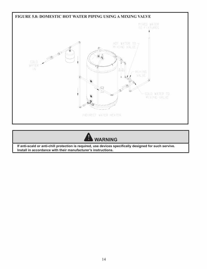
PIPING WITH A “TEMPERATURE LIMITING VALVE”Usually, the maximum temperature of the outlet water will stay near the setting of the control. In some cases, however, hot water usagepatternscancausetheoutletwatertemperaturetorisesignificantlyabovethecontrolsetting.Thetemperatureofwatergoingtothefixturesmaybemorecarefullycontrolledthroughtheuseofathermostaticmixingvalve.Thisdeviceblendsacontrolled amount of cold water with the hot water leaving the IWH so that water at a more constant temperature exits the mixing valve. Typical thermostatic mixing valve piping is illustrated in Figure 5.8. Consult a licensed plumber or the local plumbing authority for requirements in your area.
FIGURE 5.5: AQUASTAT INSTALLATION
WARNINGA thermostatic mixing valve does not eliminate the risk of scalding.
Set the thermostat as low as practical.
Feel water before bathing or showering.
If anti-scald or antichill protection is required, use devices specifically designed for such service. Install these devices in accordance with their manufacturer’s instructions.
13
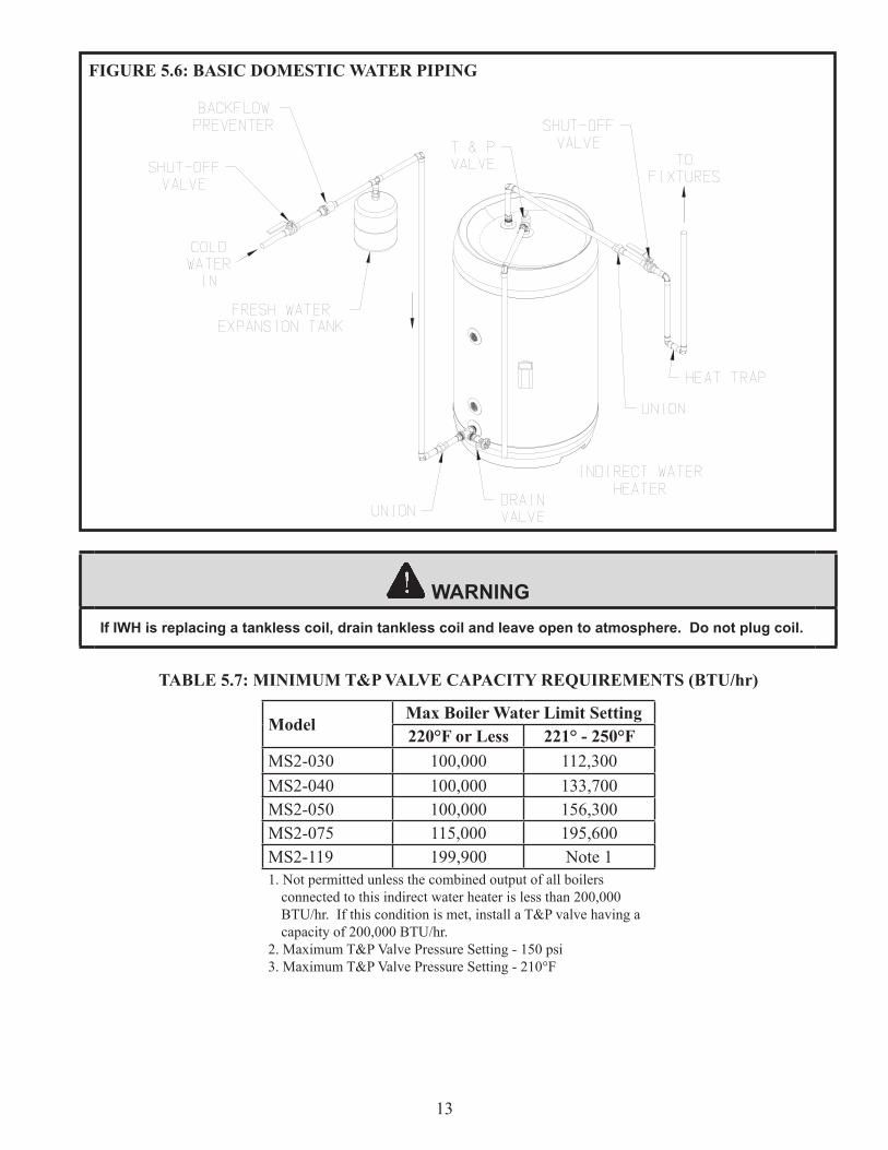
FIGURE 5.6: BASIC DOMESTIC WATER PIPING
WARNINGIf IWH is replacing a tankless coil, drain tankless coil and leave open to atmosphere. Do not plug coil.
ModelMax Boiler Water Limit Setting220°F or Less 221° - 250°F
MS2-030 100,000 112,300MS2-040 100,000 133,700MS2-050 100,000 156,300MS2-075 115,000 195,600MS2-119 199,900 Note 11. Not permitted unless the combined output of all boilers
connected to this indirect water heater is less than 200,000 BTU/hr. If this condition is met, install a T&P valve having a capacity of 200,000 BTU/hr.
2. Maximum T&P Valve Pressure Setting - 150 psi3. Maximum T&P Valve Pressure Setting - 210°F
TABLE 5.7: MINIMUM T&P VALVE CAPACITY REQUIREMENTS (BTU/hr)
14
WARNINGIf anti-scald or anti-chill protection is required, use devices specifically designed for such servive. Install in accordance with their manufacturer’s instructions.
FIGURE 5.8: DOMESTIC HOT WATER PIPING USING A MIXING VALVE
15
VI. WIRINGThe following general notes apply to all wiring:
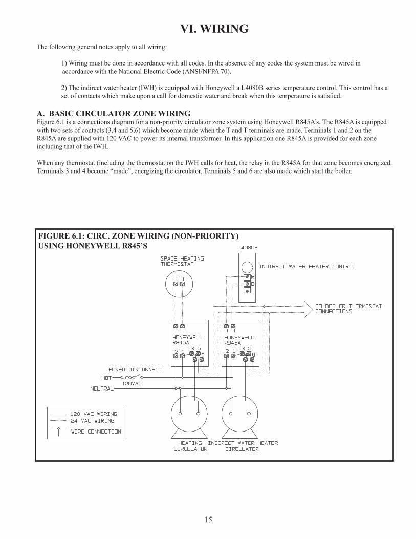
1) Wiring must be done in accordance with all codes. In the absence of any codes the system must be wired in accordance with the National Electric Code (ANSI/NFPA 70).
2) The indirect water heater (IWH) is equipped with Honeywell a L4080B series temperature control. This control has a setofcontactswhichmakeuponacallfordomesticwaterandbreakwhenthistemperatureissatisfied.
A. BASIC CIRCULATOR ZONE WIRINGFigure 6.1 is a connections diagram for a non-priority circulator zone system using Honeywell R845A’s. The R845A is equipped with two sets of contacts (3,4 and 5,6) which become made when the T and T terminals are made. Terminals 1 and 2 on the R845A are supplied with 120 VAC to power its internal transformer. In this application one R845A is provided for each zone including that of the IWH.
When any thermostat (including the thermostat on the IWH calls for heat, the relay in the R845A for that zone becomes energized. Terminals 3 and 4 become “made”, energizing the circulator. Terminals 5 and 6 are also made which start the boiler.
FIGURE 6.1: CIRC. ZONE WIRING (NON-PRIORITY)USING HONEYWELL R845’S
16
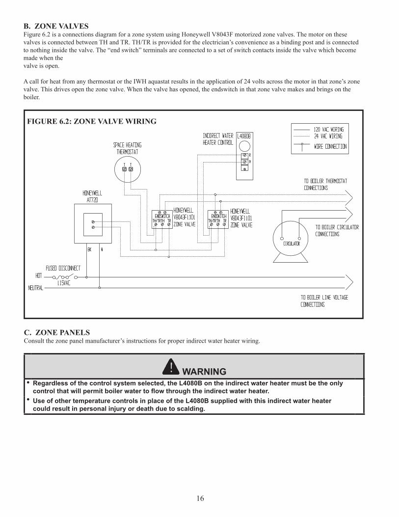
B. ZONE VALVESFigure 6.2 is a connections diagram for a zone system using Honeywell V8043F motorized zone valves. The motor on these valves is connected between TH and TR. TH/TR is provided for the electrician’s convenience as a binding post and is connected to nothing inside the valve. The “end switch” terminals are connected to a set of switch contacts inside the valve which become made when thevalve is open.
A call for heat from any thermostat or the IWH aquastat results in the application of 24 volts across the motor in that zone’s zone valve. This drives open the zone valve. When the valve has opened, the endswitch in that zone valve makes and brings on the boiler.
FIGURE 6.2: ZONE VALVE WIRING
WARNING• Regardless of the control system selected, the L4080B on the indirect water heater must be the only
control that will permit boiler water to flow through the indirect water heater.• Use of other temperature controls in place of the L4080B supplied with this indirect water heater
could result in personal injury or death due to scalding.
C. ZONE PANELSConsult the zone panel manufacturer’s instructions for proper indirect water heater wiring.
17
VII. START-UP AND CHECK-OUT 1) Make sure that the system is free of leaks and that air is purged from the system.
2)Manysolderingfluxescontainzincchloridewhichcancauseseverecorrosiondamagetostainlesssteel.Aftercompletingalldomesticwaterconnections,flushtheindirectwaterheater(IWH)thoroughlybeforeleavingthe installation. This is particularly important if the IWH will be unused for an extended period of time after installation. 3) Make sure that all electrical connections are correctly made and that no exposed high voltage wiring is present.
4) Temporarily disable the burner.
5) Make sure that each zone valve or circulator operates when, and only when, its thermostat calls for heat. Let each zone operate long enough to purge any remaining air from the system.
6) Re-enable the burner and allow the IWH zone to operate. Make sure that the IWH control shuts down the zone when it issatisfied.
7)Thesettingofcontroldeterminesthemaximumwatertemperatureinthetank.Thedifferentialofthecontrolisafixed 8°F with a 150°F maximum setting, set by the manufacturer to the lowest setting of 100°F.
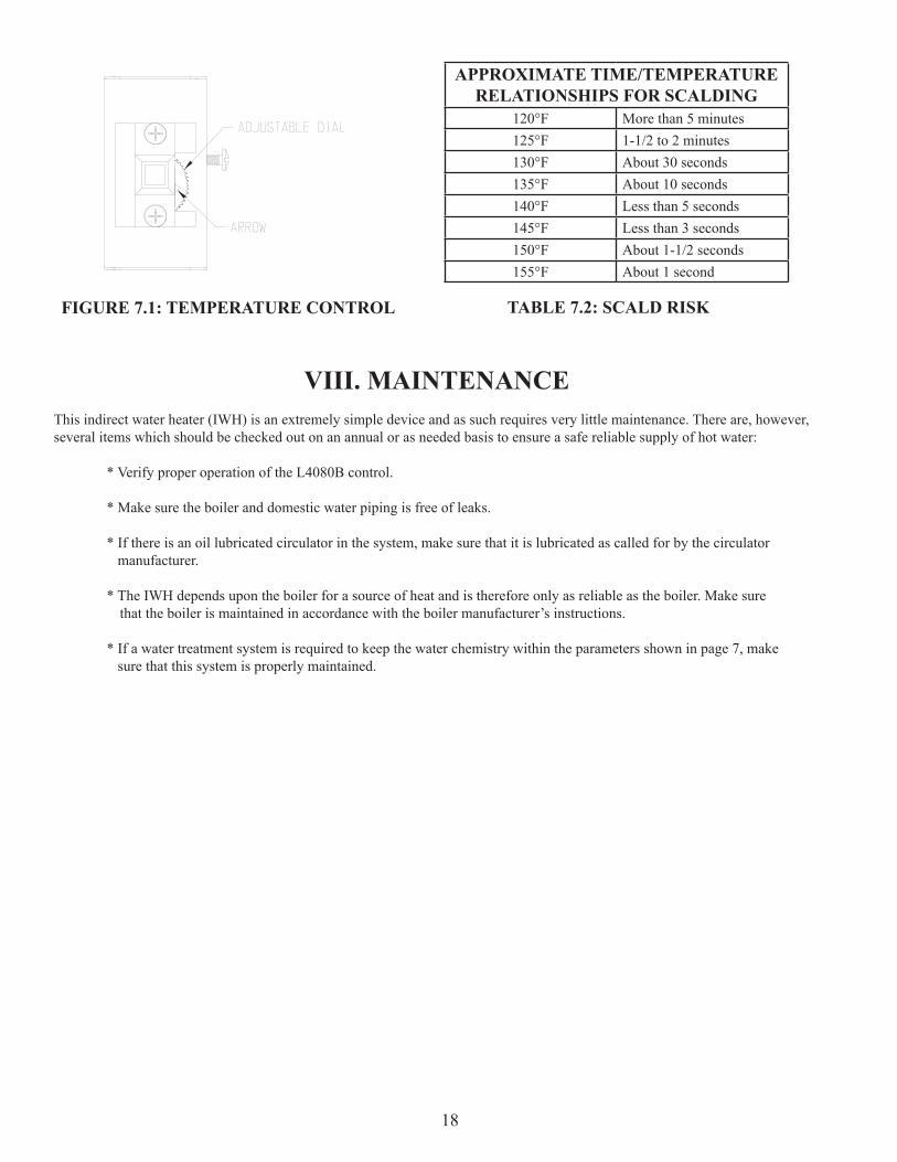
Forthemostenergyefficientoperation,adjustthecontrolfortheminimumwatertemperaturenecessarytomeet domestic water needs. Because hot water presents a scald hazard, it is best to set the control at 120ºF or lower and raise it only if necessary to provide adequate hot water. See Table 7.2 for more information about scalding.
a) Adjust the dial shown in Figure 7.1 until the desired temperature setting on the dial is aligned with the arrow shown.
b) After the IWH completes a heat-up cycle, check the water temperature at the faucet. Allow enoughwatertoflowtoensurethatthewatertemperaturereflectsthetanktemperature.AdjusttheIWHtemperature setting as necessary.
i) Adjusting to a lower temperature setting will not immediately affect the water temperature. Draw sufficientwaterorallowthewaterheatertosituntilaheat-upcycleisinitiated.Repeatstepsa)andb).
ii) Adjusting to a higher temperature setting may not immediately affect the water temperature ifaheat-upcyclebegins,returntostepsa)andb).Ifaheat-upcycledoesnotbegin,drawsufficient water or allow the water heater to sit until a heat-up cycle is initiated. Repeat steps a) and b).
DANGERNever attempt to fill a hot empty boiler
WARNINGFix any leaks found before proceeding further. Leakage from the boiler piping can result in severe damage to the boiler.
18
VIII. MAINTENANCEThis indirect water heater (IWH) is an extremely simple device and as such requires very little maintenance. There are, however, several items which should be checked out on an annual or as needed basis to ensure a safe reliable supply of hot water:
* Verify proper operation of the L4080B control.
* Make sure the boiler and domestic water piping is free of leaks.
* If there is an oil lubricated circulator in the system, make sure that it is lubricated as called for by the circulator manufacturer.
* The IWH depends upon the boiler for a source of heat and is therefore only as reliable as the boiler. Make sure that the boiler is maintained in accordance with the boiler manufacturer’s instructions.
* If a water treatment system is required to keep the water chemistry within the parameters shown in page 7, make sure that this system is properly maintained.
FIGURE 7.1: TEMPERATURE CONTROL
APPROXIMATE TIME/TEMPERATURERELATIONSHIPS FOR SCALDING
120°F More than 5 minutes125°F 1-1/2 to 2 minutes130°F About 30 seconds135°F About 10 seconds140°F Less than 5 seconds145°F Less than 3 seconds150°F About 1-1/2 seconds155°F About 1 second
TABLE 7.2: SCALD RISK
19
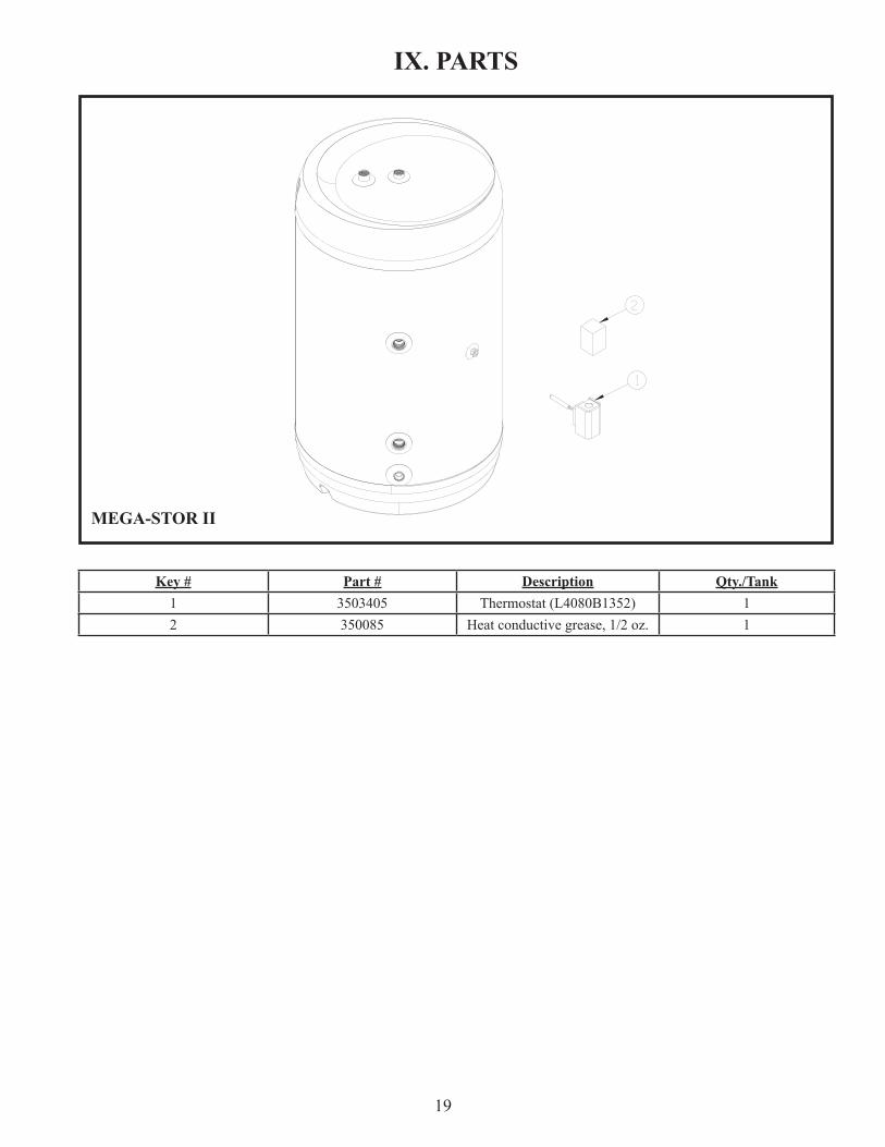
IX. PARTS
Key # Part # Description Qty./Tank1 3503405 Thermostat (L4080B1352) 12 350085 Heat conductive grease, 1/2 oz. 1
MEGA-STOR II
20
Residential Applications
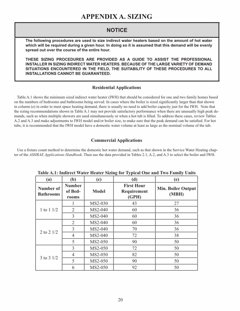
Table A.1 shows the minimum sized indirect water heater (IWH) that should be considered for one and two family homes based onthenumbersofbedroomsandbathroomsbeingserved.Incaseswheretheboilerissizedsignificantlylargerthanthatshownin column (e) in order to meet space heating demand, there is usually no need to add boiler capacity just for the IWH. Note that the sizing recommendations shown in Table A.1 may not provide satisfactory performance when there are unusually high peak de-mands,suchaswhenmultipleshowersareusedsimultaneouslyorwhenahottubisfilled.Toaddressthesecases,reviewTablesA.2andA.3andmakeadjustmentstoIWHmodeland/orboilersize,tomakesurethatthepeakdemandcanbesatisfied.Forhottubs, it is recommended that the IWH model have a domestic water volume at least as large as the nominal volume of the tub.
Commercial Applications
Useafixturecountmethodtodeterminethedomestichotwaterdemand,suchasthatshownintheServiceWaterHeatingchap-ter of the ASHRAE Applications Handbook. Then use the data provided in Tables 2.1, A.2, and A.3 to select the boiler and IWH.
Table A.1: Indirect Water Heater Sizing for Typical One and Two Family Units(a) (b) (c) (d) (e)
Number of Bathrooms
Number of Bed-rooms
ModelFirst Hour
Requirement (GPH)
Min. Boiler Output (MBH)
1 to 1 1/21 MS2-030 43 272 MS2-040 60 363 MS2-040 60 36
2 to 2 1/2
2 MS2-040 60 363 MS2-040 70 364 MS2-040 72 385 MS2-050 90 50
3 to 3 1/2
3 MS2-050 72 504 MS2-050 82 505 MS2-050 90 506 MS2-050 92 50
APPENDIX A. SIZING
NOTICE
The following procedures are used to size indirect water heaters based on the amount of hot water which will be required during a given hour. In doing so it is assumed that this demand will be evenly spread out over the course of the entire hour.
THESE SIZING PROCEDURES ARE PROVIDED AS A GUIDE TO ASSIST THE PROFESSIONAL INSTALLER IN SIZING INDIRECT WATER HEATERS. BECAUSE OF THE LARGE VARIETY OF DEMAND SITUATIONS ENCOUNTERED IN THE FIELD, THE SUITABILITY OF THESE PROCEDURES TO ALL INSTALLATIONS CANNOT BE GUARANTEED.
21
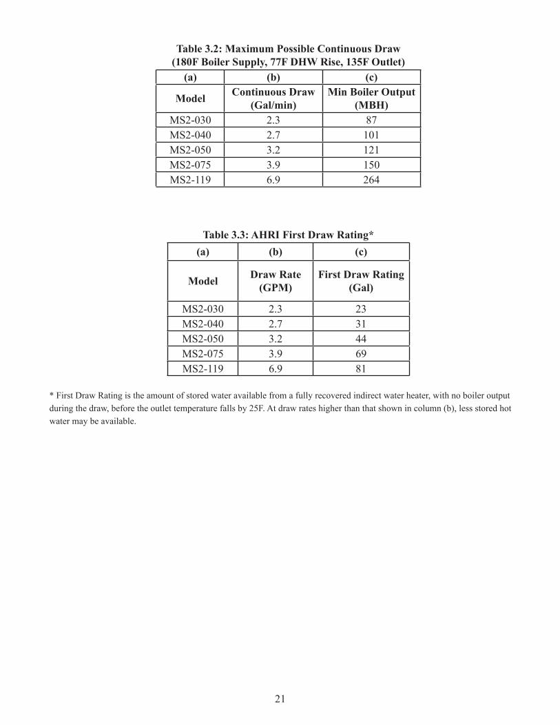
Table 3.2: Maximum Possible Continuous Draw(180F Boiler Supply, 77F DHW Rise, 135F Outlet)
(a) (b) (c)
Model Continuous Draw (Gal/min)
Min Boiler Output (MBH)
MS2-030 2.3 87MS2-040 2.7 101MS2-050 3.2 121MS2-075 3.9 150MS2-119 6.9 264
Table 3.3: AHRI First Draw Rating*(a) (b) (c)
Model Draw Rate(GPM)
First Draw Rating (Gal)
MS2-030 2.3 23MS2-040 2.7 31MS2-050 3.2 44MS2-075 3.9 69MS2-119 6.9 81
* First Draw Rating is the amount of stored water available from a fully recovered indirect water heater, with no boiler output during the draw, before the outlet temperature falls by 25F. At draw rates higher than that shown in column (b), less stored hot water may be available.
22
CONSUMER WARRANTY INFORMATION
MEGA‐STOR2: STAINLESS STEEL INDIRECT WATER HEATER
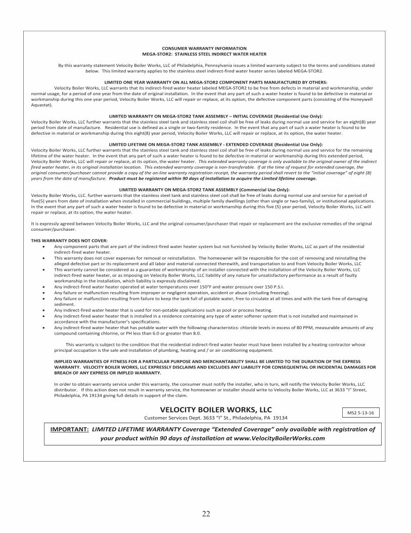
By this warranty statement Velocity Boiler Works, LLC of Philadelphia, Pennsylvania issues a limited warranty subject to the terms and conditions stated below. This limited warranty applies to the stainless steel indirect‐fired water heater series labeled MEGA‐STOR2.
LIMITED ONE YEAR WARRANTY ON ALL MEGA‐STOR2 COMPONENT PARTS MANUFACTURED BY OTHERS:
Velocity Boiler Works, LLC warrants that its indirect‐fired water heater labeled MEGA‐STOR2 to be free from defects in material and workmanship, under normal usage, for a period of one year from the date of original installation. In the event that any part of such a water heater is found to be defective in material or workmanship during this one year period, Velocity Boiler Works, LLC will repair or replace, at its option, the defective component parts (consisting of the Honeywell Aquastat).
LIMITED WARRANTY ON MEGA‐STOR2 TANK ASSEMBLY – INITIAL COVERAGE (Residential Use Only):
Velocity Boiler Works, LLC further warrants that the stainless steel tank and stainless steel coil shall be free of leaks during normal use and service for an eight(8) year period from date of manufacture. Residential use is defined as a single or two‐family residence. In the event that any part of such a water heater is found to be defective in material or workmanship during this eight(8) year period, Velocity Boiler Works, LLC will repair or replace, at its option, the water heater.
LIMITED LIFETIME ON MEGA‐STOR2 TANK ASSEMBLY ‐ EXTENDED COVERAGE (Residential Use Only):
Velocity Boiler Works, LLC further warrants that the stainless steel tank and stainless steel coil shall be free of leaks during normal use and service for the remaining lifetime of the water heater. In the event that any part of such a water heater is found to be defective in material or workmanship during this extended period, Velocity Boiler Works, LLC will repair or replace, at its option, the water heater. This extended warranty coverage is only available to the original owner of the indirect fired water heater, in its original installation location. This extended warranty coverage is non‐transferable. If at the time of request for extended coverage, the original consumer/purchaser cannot provide a copy of the on‐line warranty registration receipt, the warranty period shall revert to the “initial coverage” of eight (8) years from the date of manufacture. Product must be registered within 90 days of installation to acquire the Limited lifetime coverage.
LIMITED WARRANTY ON MEGA‐STOR2 TANK ASSEMBLY (Commercial Use Only): Velocity Boiler Works, LLC. further warrants that the stainless steel tank and stainless steel coil shall be free of leaks during normal use and service for a period of five(5) years from date of installation when installed in commercial buildings, multiple family dwellings (other than single or two‐family), or institutional applications. In the event that any part of such a water heater is found to be defective in material or workmanship during this five (5) year period, Velocity Boiler Works, LLC will repair or replace, at its option, the water heater. It is expressly agreed between Velocity Boiler Works, LLC and the original consumer/purchaser that repair or replacement are the exclusive remedies of the original consumer/purchaser. THIS WARRANTY DOES NOT COVER:
Any component parts that are part of the indirect‐fired water heater system but not furnished by Velocity Boiler Works, LLC as part of the residential indirect‐fired water heater.
This warranty does not cover expenses for removal or reinstallation. The homeowner will be responsible for the cost of removing and reinstalling the alleged defective part or its replacement and all labor and material connected therewith, and transportation to and from Velocity Boiler Works, LLC
This warranty cannot be considered as a guarantee of workmanship of an installer connected with the installation of the Velocity Boiler Works, LLC indirect‐fired water heater, or as imposing on Velocity Boiler Works, LLC liability of any nature for unsatisfactory performance as a result of faulty workmanship in the installation, which liability is expressly disclaimed.
Any indirect‐fired water heater operated at water temperatures over 150°F and water pressure over 150 P.S.I. Any failure or malfunction resulting from improper or negligent operation, accident or abuse (including freezing). Any failure or malfunction resulting from failure to keep the tank full of potable water, free to circulate at all times and with the tank free of damaging
sediment. Any indirect‐fired water heater that is used for non‐potable applications such as pool or process heating. Any indirect‐fired water heater that is installed in a residence containing any type of water softener system that is not installed and maintained in
accordance with the manufacturer’s specifications. Any indirect‐fired water heater that has potable water with the following characteristics: chloride levels in excess of 80 PPM, measurable amounts of any
compound containing chlorine, or PH less than 6.0 or greater than 8.0.
This warranty is subject to the condition that the residential indirect‐fired water heater must have been installed by a heating contractor whose principal occupation is the sale and installation of plumbing, heating and / or air conditioning equipment. IMPLIED WARRANTIES OF FITNESS FOR A PARTICULAR PURPOSE AND MERCHANTABILITY SHALL BE LIMITED TO THE DURATION OF THE EXPRESS WARRANTY. VELOCITY BOILER WORKS, LLC EXPRESSLY DISCLAIMS AND EXCLUDES ANY LIABILITY FOR CONSEQUENTIAL OR INCIDENTAL DAMAGES FOR BREACH OF ANY EXPRESS OR IMPLED WARRANTY. In order to obtain warranty service under this warranty, the consumer must notify the installer, who in turn, will notify the Velocity Boiler Works, LLC distributor. If this action does not result in warranty service, the homeowner or installer should write to Velocity Boiler Works, LLC at 3633 “I” Street, Philadelphia, PA 19134 giving full details in support of the claim.
VELOCITY BOILER WORKS, LLC Customer Services Dept. 3633 “I” St., Philadelphia, PA 19134
MS2 5‐13‐16
IMPORTANT: LIMITED LIFETIME WARRANTY Coverage “Extended Coverage” only available with registration of your product within 90 days of installation at www.VelocityBoilerWorks.com