Embed Size (px)
Citation preview

Revised August, 2004
10 TEGAM WAY • GENEVA, OHIO 44041 • 440-466-6100 • FAX 440-466-6110
R1M-A, R1M-AR
MEGOHMMETER
MODEL R1M-A, R1M-AR
Operation and Maintenance Manual
PN# R1M-A-900-01
Publication Date: December 2012
REV. C
REPRODUCTION AND DISTRIBUTION OF THIS TECHNICAL MANUAL IS AUTHORIZED FOR US
GOVERNMENT PURPOSES. TEGAM PROPRIETARY INFORMATION.
NOTE: This User’s Manual was as current as possible when this product was manufactured. However,
products are constantly being updated and improved. To ensure you have the latest documentation, refer
to www.tegam.com
Revised August, 2004
10 TEGAM WAY • GENEVA, OHIO 44041 • 440-466-6100 • FAX 440-466-6110
TABLE OF CONTENTS
TABLE OF CONTENTS
1. INSTRUMENT DESCRIPTION
Purpose ........................................................................ 1-1 Performance Characteristics ............................................ 1-1 Description of Equipment ................................................ 1-2 List of Items Furnished ................................................... 1-3 Storage and Shipping Requirements ................................. 1-3
2. PREPARATION FOR USE AND INSTALLATION
Unpacking and Inspection ............................................... 2-1
Preparation for Use ........................................................ 2-1 Figure 1: Connection Diagram ..................................... 2-3
3. OPERATING INSTRUCTIONS
Pushbutton Functions ..................................................... 3-1 General Theory of Operation ........................................... 3-2
4. PRINCIPLES OF OPERATION
5. MAINTENANCE
Inspection ..................................................................... 5-1
Cleaning ....................................................................... 5-1 Test Equipment required for Calibration and Repair ............ 5-1
Performance Verification ................................................. 5-2 Calibration .................................................................... 5-3 Troubleshooting ............................................................. 5-4
Table 2: Fault Symptoms and Repair Actions ................. 5-5 Preparation for Shipment ................................................ 5-6 Overhaul Instructions ..................................................... 5-6
Figure 2: Front Panel Controls ..................................... 5-7 Figure 3: Front Panel-Rear View .................................. 5-8
Figure 4: Simplified Block Diagram .............................. 5-9
Figure 5: Power Supply Schematic ............................. 5-10 Figure 6: Power Supply Layout .................................. 5-11
Figure 7a, 7b: Display Board Schematic ...................... 5-12 Figure 8: Display Board Parts Layout .......................... 5-14
Figure 9: System (Side View) Layout ......................... 5-15 Table 3, 4, 5, 6: Parts List ........................................ 5-16
Table 7: Vendor Cage Code Directory ......................... 5-19
6. SERVICE INFORMATION Preparation for Repair or Calibration Service ..................... 6-1 Expedite Repair and Calibration Form ............................... 6-2
Warranty ...................................................................... 6-3
Revised August, 2004
10 TEGAM WAY • GENEVA, OHIO 44041 • 440-466-6100 • FAX 440-466-6110
• [email protected] 1-1
INSTRUMENT DESCRIPTION
SECTION 1
INSTRUMENT DESCRIPTION
INTRODUCTION
1.1 Purpose
The Model RIM-A Megohmmeter is a portable instrument used
to measure high values of resistance. It is enclosed in a
rugged weather-resistant housing designed for severe
industrial and military applications.
The Model RIM-A may be used to measure resistances
between 50 kΩ and 10 GΩ with 50 V test voltage, and
between 1 MΩ and 200 GΩ with 100 V, 250 V, or 500 V test
voltage.
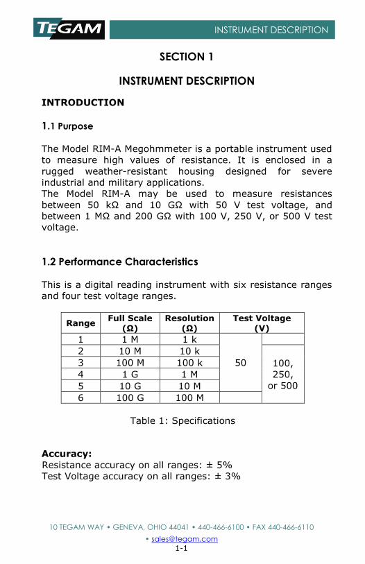
1.2 Performance Characteristics
This is a digital reading instrument with six resistance ranges
and four test voltage ranges.
Range Full Scale
(Ω) Resolution
(Ω) Test Voltage
(V)
1 1 M 1 k
50
2 10 M 10 k
100,
250,
or 500
3 100 M 100 k
4 1 G 1 M
5 10 G 10 M
6 100 G 100 M
Table 1: Specifications
Accuracy:
Resistance accuracy on all ranges: ± 5%
Test Voltage accuracy on all ranges: ± 3%
Revised August, 2004
10 TEGAM WAY • GENEVA, OHIO 44041 • 440-466-6100 • FAX 440-466-6110
• [email protected] 1-2
INSTRUMENT DESCRIPTION
1.3 Description of Equipment
Physical: A rugged heavy-duty case is provided to contain
and protect the instrument. When closed, a gasket seals the
lid to protect the instrument against water and dirt while the
instrument is carried through rainstorms or other hazardous
conditions. The lid is secured by two latches. A handle is
provided for portability. A compartment is provided for
storage of test cables and line cord.
Dimensions: 216 mm (8.5”) x 228 mm (9”) x 152 mm (6”).
Weight is 2.3 kg (5 lb). Controls and connectors are of a size
and spacing such that the instrument may be operated while
wearing safety gloves.
Electrical: Input power is from the AC power line (103.5 V to
129 V at 50 Hz or 60 Hz, at less than 1/8 A).
Environmental: This unit will operate over a temperature
range from 0 °C to 50 °C, 75% RH non-condensing, up to
3050 m altitude. Withstand functional shock of 40 G for 11
ms. Vibration: 2 G maximum at 5 Hz to 55 Hz.
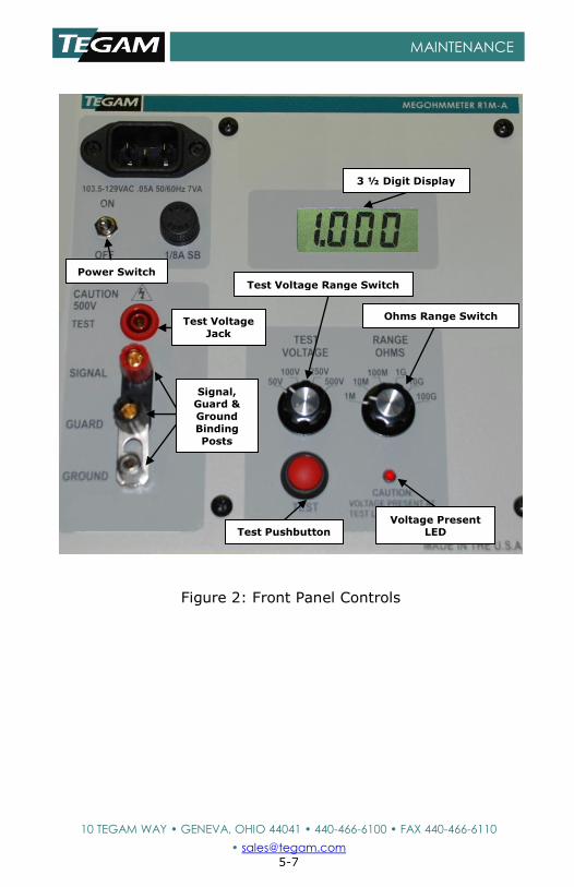
Front Panel Controls and Displays (See figure 2)
OHMS RANGE Switch is a rotary six position selector switch used to step through all six ranges.
TEST VOLTAGE RANGE Switch is a rotary four position selector switch used to step through all four voltage ranges.
POWER Switch is used to turn the power on or off to the instrument.
TEST pushbutton is a round sealed switch. This pushbutton
switch turns on the power to the unit. A LED is provided to
indicate that the test voltage is on.
DISPLAY is a 3 ½ digit LCD, displaying readings from 1.999
to 199.9.
Revised August, 2004
10 TEGAM WAY • GENEVA, OHIO 44041 • 440-466-6100 • FAX 440-466-6110
• [email protected] 1-3
INSTRUMENT DESCRIPTION
TEST VOLTAGE Jack is recessed to prevent any accidental
encounter.
Three Binding Posts for connection of test leads are marked SIG (Signal), GUARD and GND (Ground). Proper connections to the resistor under test are described in Section 2.2 below.
WARNING DO NOT TOUCH THE BINDING POSTS WHEN THEY ARE
CONNECTED TO EXTERNAL CIRCUITS. LETHAL
VOLTAGES MAY BE PRESENT AT THESE POSTS.
1.4 List of Items Furnished
1 each Model R1M-A with power cord
2 each test cables, one shielded with two alligator clips
and the other with one alligator clip
1 each R1M-A Instruction Manual
1.5 Storage and Shipping Requirements
Standard precautions which apply to electronic test instruments should be followed. A hard mechanical shock, such as from dropping the R1M-A, could damage the liquid crystal display. Care should be taken to prevent damage to associated cables.
The R1M-A should be stored in a relatively dust-free environment.
Temperature: -40 °C to +71 °C.
Relative humidity: 0 to 100%, non-condensing.
Altitude: 4570 m
See Section 5.7 below for shipping requirements.
Revised August, 2004
10 TEGAM WAY • GENEVA, OHIO 44041 • 440-466-6100 • FAX 440-466-6110
• [email protected] 2-1
PREPARATION FOR USE AND INSTALLATION
SECTION 2
PREPARATION FOR USE AND INSTALLATION
2.1 Unpacking and Inspection
Upon receipt, the R1M-A and accessories should be carefully
unpacked and removed from the shipping container.
Separate the units from the packing material and inspect
both the instrument and the accessories for any external
damage.
If any dents, broken, or loose parts are seen, do not use
the equipment. Notify the shipping company immediately
and follow their instructions as to how to proceed.
Check that all items are present. If any items are missing,
notify the shipper if this is a new instrument. If not new,
contact the previous user to locate the missing item(s).
2.2 Preparation for Use
Release the two latches which secure the lid and open the
lid. Remove the power cord and the two test cables which
are stored in the side compartment. If desired, the lid may
then be removed by pushing it to the right.
Set the ‘TEST VOLTAGE’ rotary switch to the desired value,
from 50 V to 500 V and set the ‘OHMS RANGE’ switch to the
anticipated range.
Note that although the ‘OHMS RANGE’ switch is marked from
1 M to 100 G, a 100% over-range capability is built into this
instrument.
Note also, that for resistance values less than 1 MΩ, the only
test voltage that should be used is 50 V. No damage will
occur if a higher voltage is selected, but the readings may
not be accurate. Do not measure resistors less than 50 kΩ
with the R1M-A; it may damage the instrument.
WARNING SHORTING THE ‘TEST’ and ‘SIGNAL’ LEADS TOGETHER WILL
CAUSE INSTRUMENT DAMAGE.
Revised August, 2004
10 TEGAM WAY • GENEVA, OHIO 44041 • 440-466-6100 • FAX 440-466-6110
• [email protected] 2-2
PREPARATION FOR USE AND INSTALLATION
Power Up
Plug the power cord into a source of AC power (103.5 V to
129 V at 50 Hz or 60 Hz). Check that the other end is
plugged securely into the power input receptacle on the front
panel and turn on the POWER toggle switch.
Connections to DUT
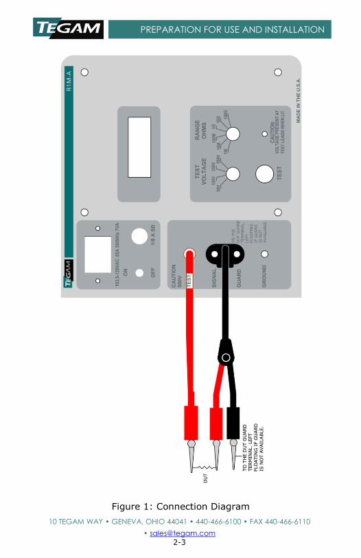
One test cable has a double banana plug at one end and red
and black insulated alligator clips at the other end. This is
the shielded test cable. Connect the red alligator clip to one
end of the resistor under test. Connect the black clip to the
guard circuit, if any. If no guard is available, this clip may be
left floating (it is connected to the cable shield and to the
R1M-A guard circuit at the other end) however, this clip must
not be allowed to make accidental contact with any part of
the external circuit. Plug the dual-banana plug on this cable
into the SIG and GUARD binding posts. Note that the pin
marked GROUND should go into the GUARD binding post. If
there is no guard available and the black alligator clip at the
other end of the test cable is left floating, the operator may
choose to orient the dual banana plug so that the GROUND
pin is NOT plugged into the GUARD binding post. This will
ensure that any accidental contact of the black alligator clip
will cause no problem; however, the cable shield will then be
floating and the signal may be excessively noisy.
The other test cable has a shrouded banana plug on one end
and an insulated alligator clip on the other end. This cable
carries the high voltage output of the R1M-A to the resistor
under test. Connect the alligator clip to the other end of the
resistor under test; then plug the shrouded banana plug into
the recessed (RED) ‘TEST’ jack. Please refer to the
connection diagram (figure 1) below.
The shorting link on the GROUND binding post may be
swung around and connected to the GUARD binding post to
ground the R1M-A circuitry. This may be done only if there is
no external voltage with respect to ground on the measured
resistor or guard.
Revised August, 2004
10 TEGAM WAY • GENEVA, OHIO 44041 • 440-466-6100 • FAX 440-466-6110
• [email protected] 2-3
PREPARATION FOR USE AND INSTALLATION
Figure 1: Connection Diagram
Revised August, 2004
10 TEGAM WAY • GENEVA, OHIO 44041 • 440-466-6100 • FAX 440-466-6110
• [email protected] 3-1
OPERATING INSTRUCTIONS
SECTION 3
OPERATING INSTRUCTIONS
The R1M-A is designed for bench-top or field operation. Use
the cables connecting their banana plug terminations to the
appropriate connectors explained in Section 2.2.
WARNING DO NOT TOUCH ANY ALIGATOR CLIP WHILE DEPRESSING THE
TEST PUSHBUTTON. LETHAL VOLTAGES MAY BE PRESENT ON THESE CLIPS.
3.1 Rotary Switch Functions
The two rotary switches manually scroll through the six
resistance and four voltage ranges.
Full scale on any range may be described as 2,000 (actually
1,999), since this is a 3 ½ digit meter. If the readings are
exceeding 1,999 counts, step to the next higher range. If the
readings are less than 2,000 counts, step down a range, so
that it will read 1,999 counts, or less. The decimal point is
located automatically for the correct reading.
If the selected range is too low for the value of the resistor
under test, the display will show over-range by showing “1”
on the display. Similarly, the under-range condition is
displayed by showing negative readings on the display. “-1”
is displayed on the display until the test button is pressed.
The POWER switch turns on the power to operate the unit or
turns off the power to the unit. Note that when power is
turned off, it may take several seconds to discharge circuit
capacity to completely blank the display. The black markings
seen have no effect and disappear when power is turned
back on.
WARNING TAKING RESISTANCE MEASUREMENTS ON A POWERED OR
ENERGIZED COMPONENT COULD CAUSE SERIOUS HARM
TO THE OPERATOR AND/OR DAMAGE THE R1M-A. BE
SURE THE ITEM TO BE MEASURED IS DISCONNECTED
FROM OTHER COMPONENTS AND APPARATUS.
Revised August, 2004
10 TEGAM WAY • GENEVA, OHIO 44041 • 440-466-6100 • FAX 440-466-6110
• [email protected] 3-2
OPERATING INSTRUCTIONS
3.2 General Theory Of Operation
A 2-terminal measurement method is used to determine the
resistance of the item under test. The R1M-A calculates the
resistance of the item under test utilizing Ohm's law and
displays it on a 3 ½ digit display. To obtain the best accuracy, allow the R1M-A to warm up for 15 to 30 minutes before making measurements. In any case, a minimum warm-up of 30 seconds is advised.
Depress the TEST pushbutton, which switches on the high
voltage. Note that the red LED will light, indicating that high
voltage is present on the terminal. Allow for a brief settling
time and read the resistance on the digital display. Note that
the operating range of resistance values which may be read
on any given range extends from 5% to 199.9% of the
nominal value of the selected range. Note that readings
greater than 100% will take more time. Thus, the 1 MΩ
range may be used to measure resistors from 50 kΩ to
1.999 MΩ. Note that the test voltage must be 50 V for
resistances less than 1 MΩ. If the resistance measured
exceeds the maximum value for the selected range, the
display will show blanks; in that case, set the range switch to
a higher range. If the resistance measured is less than 5% of
the nominal value of the selected range, the display will
show a minus sign; if so, switch to a lower range, since the
readings may be inaccurate.
If readings are noisy, especially at very high values of
resistance, it may be caused by 60 Hz coupled to the test
resistance from the power line. Note that at 100 GΩ, an
extremely small capacitance will couple many volts into the
test resistance from a power line. If so, it may be necessary
to interpose a grounded shield plate or to put the unknown
resistor into a metal box, connected to the GUARD alligator
clip.
To close up the R1M-A, first reattach the lid to the main
case, if it has been removed. Then store the power cord and
test cables in the side compartment.
Revised August, 2004
10 TEGAM WAY • GENEVA, OHIO 44041 • 440-466-6100 • FAX 440-466-6110
• [email protected] 4-1
PRINCIPLES OF OPERATION
SECTION 4
PRINCIPLES OF OPERATION
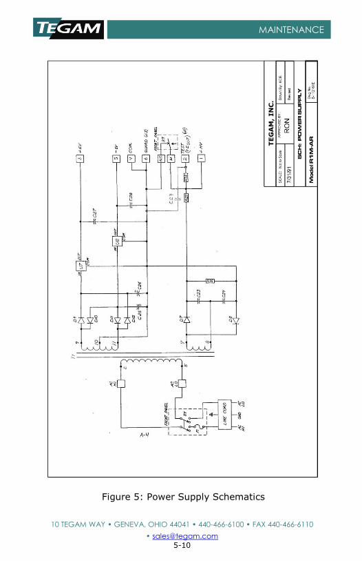
The power supply uses a transformer with two secondary
windings. The low-voltage winding is a center-tapped
winding. Diodes D9 and D12 provide rectified + power
filtered by C26 and regulated at +6 V by D7. Diodes D10 and
D11 provide rectified - power, filtered by C25 and regulated
at -6 V by D8. The high-voltage winding on T-1 charges C23
through D7 and C24 through D8. Since these two capacitors
are connected in series, this circuit functions as a voltage
doubler to provide a high voltage nearly equal to twice the
peak voltage of the high voltage winding. This high voltage is
at least 650 V at low line in order to provide 500 V test
voltage with 1 IDA of I x R drop across R37.
R37, a series resistor, is followed by Q1, a high-voltage
shunt regulator, to regulate the high voltage supply at the
selected value. R38 provides protection for Q1 from excess
current caused by external voltages. R6-R9 operate as a
four-section voltage divider, dividing the voltage from U2, a
2.5 V precision voltage reference, to 0.25, 0.5; 1.25, and 2.5
V. The voltage selected by S1 A, the ‘TEST VOLTAGE’
selection switch, is fed into pin 9 of U1, a quad operational
amplifier. The high voltage output is divided by R3 and R4 to
1/200 of the high voltage output. This divided voltage is fed
to pin 10 of U1, where it is compared with the selected
reference voltage. If the divided output is higher than the
reference, the output (pin 8) of U1 goes more positive,
increasing the base current drive to Q1. Since this is a shunt
regulator, the output high voltage decreases, until an
equilibrium point is reached. Thus, the high voltage is
regulated at the selected value.
When a resistor is not being tested, S3 (the ‘TEST’ switch) is
closed, shorting out the high voltage. This also provides
added safety in the event that the external circuit under test
contains capacitors. If so, they will be charged during ‘TEST’,
but discharged automatically as soon as S3 is released.
Revised August, 2004
10 TEGAM WAY • GENEVA, OHIO 44041 • 440-466-6100 • FAX 440-466-6110
• [email protected] 4-2
PRINCIPLES OF OPERATION
When the ‘TEST’ switch S3 is pressed, the high voltage is no
longer shorted out and it will be outputted at the ‘TEST’ jack.
Current will then flow through the resistor under test to the
SIG binding post and then to the wiper of S2A, the OHMS
RANGE selector switch. This current then passes through the
selected resistor, R16 through R21. The IR drop generated
shows up as a negative voltage at the output, pin 6, of U3.
U3 is an extremely low bias current amplifier, so that less
than 1 pA is diverted into its input. Also, the protection
diodes, Q5 and Q6, are low leakage transistors. Thus, even
currents as low as 1 nA, generated by a 100 V test voltage
and a 100 GΩ resistor, are passed with essentially no loss.
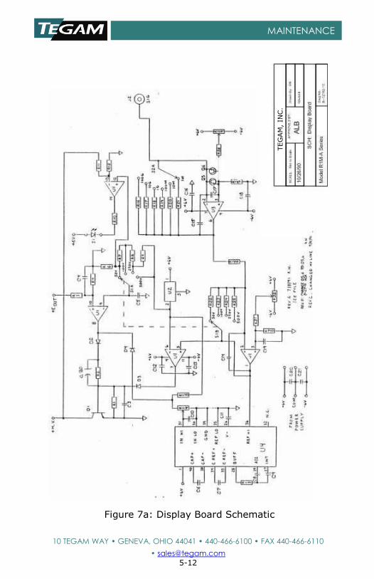
NOTE: D5 and D6 on the display board parts layout (Figure
8) correspond to Q5 and Q6 on the display board schematic
(Figure 7a). This is due to the fact that transistors are being
used as diodes.
NOTE: The action of D3 is to create a virtual ground at the
input (pin 2) and at the ‘SIG’ binding post. This has the
advantage that the full value of the test voltage is developed
across the resistor under test, with no error caused by the
current monitoring resistor, R16 through R21. A second
advantage is that the power common may then be used as a
guard voltage because it is essentially at the same potential
as the ‘SIG’ binding post.
The signal current through the resistor under test increases
with increasing test voltage. Thus, the IR drop at the output
of U3 varies with the test voltage. The signal current with 50
V test voltage and a 1 MΩ test resistor is 50 µA. With S2A
set to the 1 MΩ range, this current flows through R21, 499
Ω. Thus, the voltage at the output of U3 is 25 mV. For higher
resistance ranges, S2A selects higher values of resistance,
R20 (4.99 kΩ), R19 (49.9 kΩ), etc. to compensate for
decreasing values of signal current. Thus, the output of U3
remains at 25 mV for full-scale test resistors for all ranges,
with 50 V test voltage.
However, if the test voltage is increased, the signal current
and the voltage output of U3 will increase. To compensate
for this, the amplifier section of U1 having pins 1, 2, and 3
Revised August, 2004
10 TEGAM WAY • GENEVA, OHIO 44041 • 440-466-6100 • FAX 440-466-6110
• [email protected] 4-3
PRINCIPLES OF OPERATION
changes gain with the test voltage. With 50 V, its gain is set
by S1B and R22 at 4.23x so the output at pin 1 is 106 mV.
With 500 V, the gain is decreased to 0.423x so the output
remains at 106 mV, even though the increased test voltage
increases the signal current by ten times.
As indicated above, the output at pin 1 of U1 is 106 mV for
full-scale resistor values of any range and with any test
voltage. For smaller resistors, this voltage increases. At 5%
of full scale, this voltage is approximately 2.12 V,
approaching its upper limit. If the value of resistance under
test is less than 5% of the selected range, the voltage at pin
1 of U1 will exceed 2.12 V. This voltage is connected to pin 5
of U1, where it is compared with the 2.5 V reference from
U2. If the voltage exceeds 2.5 V, the output at pin 7 of U1
goes positive, increasing the base current to the shunt
regulator Q1 and reducing the output high voltage. When
this happens, the normal regulating section of U1, with
output pin 8 (which is normally somewhat positive to control
Q1) turns off and pin 8 goes full negative, trying to increase
the value of the high voltage. This negative voltage is
coupled to the input pin of the A/D IC, U4, via diode D4.
Thus, the display will show a minus sign to indicate that the
resistor is too small for the selected range and a smaller
range should be selected.
U4 is a 3 ½ digit A/D converter and LCD driver, functioning
as a digital voltmeter. However, since the test current and
voltage are inversely proportional to the test resistance, the
digital voltmeter is operated as a ratio meter, with a fixed DC
voltage as the normal input to pin 31, and the test voltage
signal connected to the normal reference input, pin 36.
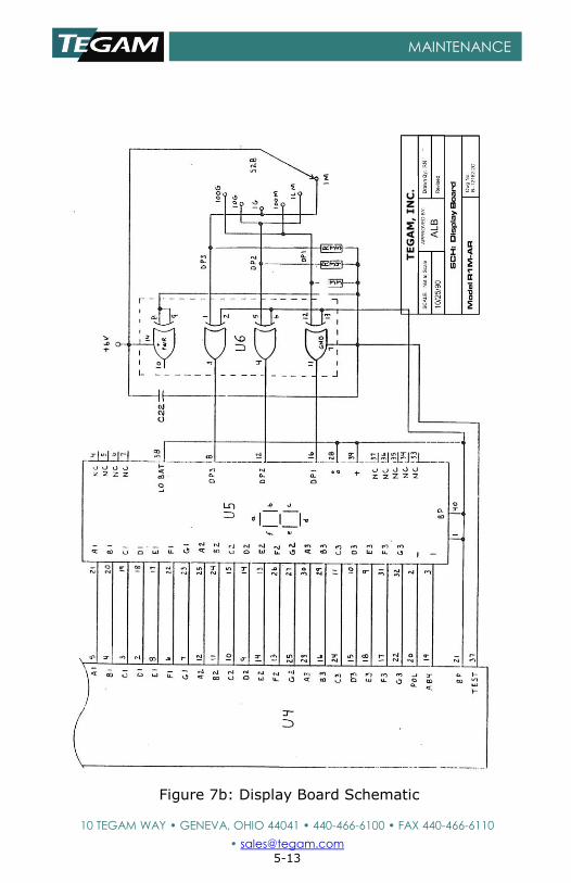
U5 is a 3 ½ digit liquid crystal display, driven segment by
segment by U4. S2B provides the proper logic levels to the
quad exclusive-or gate U6 to locate the decimal point on the
display. R33, 34 and 35 are pull-down resistors.

Revised August, 2004
10 TEGAM WAY • GENEVA, OHIO 44041 • 440-466-6100 • FAX 440-466-6110
• [email protected] 5-1
MAINTENANCE
SECTION 5
MAINTENANCE
5.1 Inspection
These units should be inspected semi-annually. Cables
should be periodically inspected to make sure they are in
good condition. Check that the pushbutton and rotary
switches operate smoothly. Check all four binding posts to
ensure that they operate smoothly. Check that the case
opens and closes with no binding.
5.2 Cleaning
The instrument should be cleaned periodically, as is
necessary, using mild soap and a damp cloth both followed
by second damp rinsing cloth.
Clean the LCD window using a soft cloth moistened with
water or "Windex" type window cleaner. DO NOT use
common paper towel products as some brands may contain
fibers which could scratch the display window. DO NOT
apply significant pressure to the LCD window as it could
separate from the front panel. DO NOT use alcohol,
solvents, or harsh chemicals to clean the LCD window.
5.3 Test Equipment Required for Calibration and Repair
Calibration of the R1M-A is recommended on a yearly basis,
and is done at a temperature of 23 °C ± 1 °C.
Precision decade resistor boxes settable to 50 kΩ, 1 MΩ, 10
MΩ, 100 MΩ, 1 GΩ, 10 GΩ, and 100 GΩ with accuracy of
0.1% or better.
A standard digital voltmeter: 3 ½ digits minimum, with 19.99
and 999 V ranges, accuracy of 0.02% of reading or better.
HP/Agilent 34401A or equivalent.
Revised August, 2004
10 TEGAM WAY • GENEVA, OHIO 44041 • 440-466-6100 • FAX 440-466-6110
• [email protected] 5-2
MAINTENANCE
Oscilloscope: 20 MHz minimum bandwidth, 5 mV/div.
sensitivity. Tektronix Model 2205 or equivalent
Screwdrivers: Phillips No.2 and small flat-bladed
5.4 Performance Verification
WARNING DO NOT TOUCH ANY ALLIGATOR CLIP WHILE THE TEST
PUSHBOTTUN IS PRESSED. LETHAL VOLTAGES MAY BE PRESENT ON THESE CLIPS.
1. Check the test voltages. Connect a DVM with at least 1
MΩ resistance between the ‘TEST’ (high) jack and the
‘SIG’ (low) binding post. Note that the OHMS RANGE
switch must be on the 1 MΩ range, or the short circuit
protection circuit may start to shut down the high voltage
power supply. Check that the voltages are as selected by
the ‘TEST VOLTAGE’ selector switch within ± 3%. If not,
there is no adjustment other than to check the various
components in the high voltage regulator circuit and to
replace any found to be defective.
2. Check that the light-emitting diode circuit is operating
correctly. It should light when the ‘TEST’ pushbutton is
depressed (provided that the resistor under test is within
the selected resistance range) (Power must be ON).
3. Check the accuracy of the resistance indication by
measuring resistors of known accuracy. Resistors
required are 50 kΩ, 1 MΩ, 10 MΩ, 100 MΩ, 1 GΩ, 10 GΩ,
and 100 GΩ. Check each range with a resistor of the
indicated value of that range and also with a resistor of
10% of that value, with the exception of the 1 MΩ range,
which should be checked with a 50 kΩ resistor. Check
first with 50 V and then with 500 V (but DO NOT CHECK
THE 50 kΩ AT 500 V). All readings must be within 5% of
the actual value. If not, adjust the trimpots as described
below.
Revised August, 2004
10 TEGAM WAY • GENEVA, OHIO 44041 • 440-466-6100 • FAX 440-466-6110
• [email protected] 5-3
MAINTENANCE
5.5 Calibration
WARNING DISCONNECT THE AC POWER CABLE BEFORE REMOVING THE INSTRUMENT FROM ITS CASE. LETHAL VOLATEGS ARE PRESENT WITH AC POWER CONNECTED.
Remove the four large mounting screws from the front
panel and remove the instrument from the case. The
binding posts and switch knobs may be held to assist in
removal. Note that the unit must be extracted carefully to
avoid catching the internal boards on the retaining brackets.
For calibration, only, it is not necessary to separate the
printed circuit boards. There are three trimpots on the lower
edge of the display board which may be adjusted for
calibration.
WARNING USE EXTREME CARE IN HANDLING THIS UNIT! EVEN WITHOUT OPERATING THE TEST PUSHBUTTON, THERE ARE VERY HIGH VOLTAGES PRESENT! THEY COULD BE LETHAL!
1. Connect the power cord and remove the test cables. Set
the test voltage to 50 V and the Ohms range to 1 GΩ.
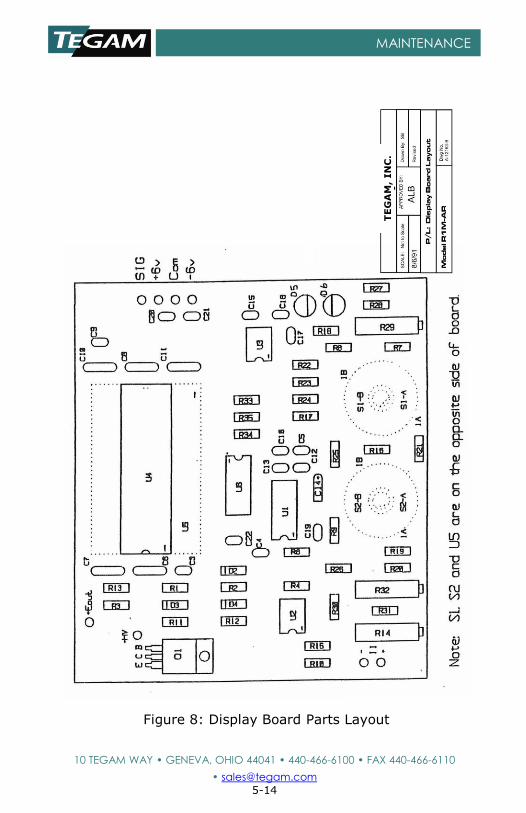
2. To adjust R29 (see Figures 7a and 8), connect the
voltmeter Low lead to R27, the side closest to D6.
Connect the High lead to R26, the side between R26 and
R20. Turn the power on. DO NOT TOUCH ANYTHING
EXCEPT THE SCREW ADJUSTMENT OF R29! Adjust R29
for 0 ± 0.1 V on the voltmeter. Turn the power off.
3. To adjust R32, connect the voltmeter High lead to R22,
the side closest to S1. Turn the power on. DO NOT
TOUCH ANYTHING EXCEPT THE SCREW ADJUSTMENT OF
R32! Adjust R32 for 0 ± 0.1 V on the voltmeter. Turn
the power off and remove the voltmeter leads.
Revised August, 2004
10 TEGAM WAY • GENEVA, OHIO 44041 • 440-466-6100 • FAX 440-466-6110
• [email protected] 5-4
MAINTENANCE
4. To adjust R14, connect the test leads to a 1 GΩ resistor
and set the voltage switch to 100 V. Turn the power on.
Very carefully operate the Test pushbutton and adjust
R14 so that the display reads between 0.990 and 1.010
GΩ (for 1% accuracy). Turn the power off.
5.6 Troubleshooting
Disassembly
After removing the unit from the cabinet, it may be
disassembled as follows:
Remove the two knobs on the rotary switches.
Remove the four small screws holding the power
supply board to the threaded spacers.
Remove the four front panel screws that pass through
the front panel, metal tubular spacers, nylon washers,
the display board, into the threaded spacers.
The two boards may now be separated for service.
Re-assembly
After trouble-shooting and repair, re-assemble in reverse
order from above.
Following are possible symptoms, diagnosis, and repair
suggestions for use in trouble-shooting (the most likely
causes are listed first). Note that the TEST button must be
held in for most of these tests; do not try to bypass it
because it is a safety feature, shorting the high voltage
supply.
Note that even with the TEST button released; high voltage
still exists between the transformer secondary and R37.
Revised August, 2004
10 TEGAM WAY • GENEVA, OHIO 44041 • 440-466-6100 • FAX 440-466-6110
• [email protected] 5-5
MAINTENANCE
SYMPTOM FAULTY
COMPONENT REPAIR
No Display Line Power Line Fuse TEST pushbutton U5/U6
T1, D9 & 12, or U7
T1, D10 & 11, or U8 U4 or U5
Check power cord & power. Check fuse. Depress the TEST pushbutton and see if the LED comes on. If so, check for a square
wave at pin 40 of U4 and/or replace U5/U6. If not, check for proper
power supply voltages and check or replace fuse. Check for +6 V. If not, trace & replace bad part.
Check for -6 V. If not trace & replace bad part. Replace U4 or U5.
No Test Voltage T1 D7, 8 C23, 24
R37
Check for 360 VAC pins 7-8. Replace D7, 8. Replace C23, 24.
Replace R37.
1 MΩ Range not Accurate
R21 Replace R21.
10 MΩ Range not
Accurate
R20 Replace R20.
100 MΩ Range not Accurate
R19 Replace R19.
1 GΩ Range not
Accurate
R18 Replace R18.
10 GΩ Range not Accurate
R17 Replace R17.
100 GΩ Range
not Accurate
R16 Replace R16.
Error with some test voltages
U1, S1, R22-25 Replace bad part.
All Ohm readings too high or too
low
R14 Adjustment Adjust R14.
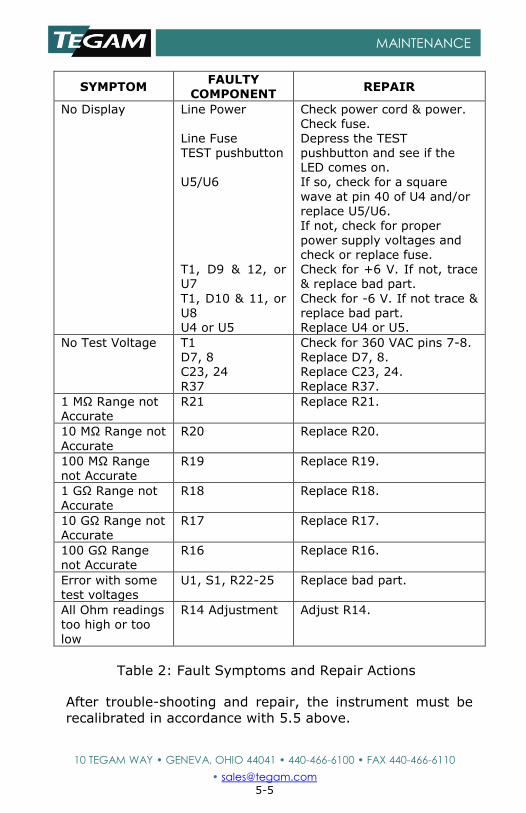
Table 2: Fault Symptoms and Repair Actions
After trouble-shooting and repair, the instrument must be
recalibrated in accordance with 5.5 above.
Revised August, 2004
10 TEGAM WAY • GENEVA, OHIO 44041 • 440-466-6100 • FAX 440-466-6110
• [email protected] 5-6
MAINTENANCE
5.7 Preparation for Shipment
The original shipping carton is not reusable.
The two test cables and line cord should be stored in the
side compartment and the lid closed and latched.
The Model R1M-AR is a rugged instrument and requires no
special covering, preservation or special cradles. Packaging
must provide sufficient resilient material, in accordance with
standard packaging practices, to prevent excessive shock to
the power supply and display during shipment.
5.8 Overhaul Instructions
The R1M-A is an all solid-state unit and requires no periodic overhaul, other than routine cleaning, inspection of cables per section 5, and calibration per section 5.5.
Tools and test equipment used for disassembly, calibration and troubleshooting of the R1M-A are listed in section 5.3. Troubleshooting suggestions are given in section 5.6.
Revised August, 2004
10 TEGAM WAY • GENEVA, OHIO 44041 • 440-466-6100 • FAX 440-466-6110
• [email protected] 5-7
MAINTENANCE
Figure 2: Front Panel Controls
Ohms Range Switch
Test Voltage Range Switch
Power Switch
Test Pushbutton
3 ½ Digit Display
Test Voltage
Jack
Voltage Present LED
Signal, Guard &
Ground
Binding
Posts
Revised August, 2004
10 TEGAM WAY • GENEVA, OHIO 44041 • 440-466-6100 • FAX 440-466-6110
• [email protected] 5-8
MAINTENANCE
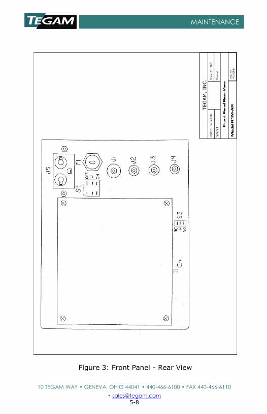
Figure 3: Front Panel - Rear View
TEG
AM
, IN
C.
Revised August, 2004
10 TEGAM WAY • GENEVA, OHIO 44041 • 440-466-6100 • FAX 440-466-6110
• [email protected] 5-9
MAINTENANCE
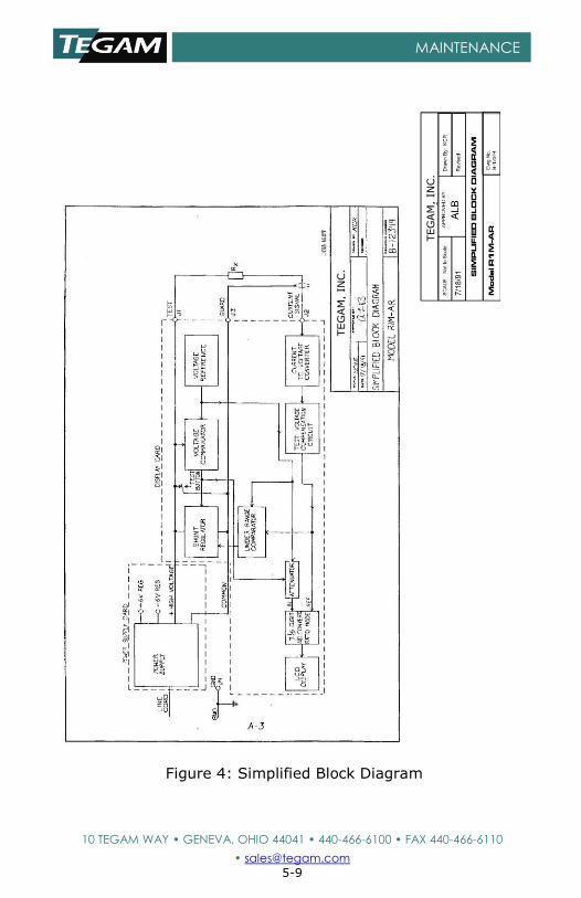
Figure 4: Simplified Block Diagram
TEG
AM
, IN
C.
TEG
AM
, IN
C.
Revised August, 2004
10 TEGAM WAY • GENEVA, OHIO 44041 • 440-466-6100 • FAX 440-466-6110
• [email protected] 5-10
MAINTENANCE
Figure 3: Digital Section
Figure 5: Power Supply Schematics
TE
GA
M,
IN
C.
Revised August, 2004
10 TEGAM WAY • GENEVA, OHIO 44041 • 440-466-6100 • FAX 440-466-6110
• [email protected] 5-11
MAINTENANCE
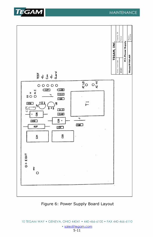
Figure 6: Power Supply Board Layout
TE
GA
M,
IN
C.
Revised August, 2004
10 TEGAM WAY • GENEVA, OHIO 44041 • 440-466-6100 • FAX 440-466-6110
• [email protected] 5-12
MAINTENANCE
Figure 4: Parts Layout
Figure 7a: Display Board Schematic
TEGAM, Inc.
TEG
AM
, IN
C.
Revised August, 2004
10 TEGAM WAY • GENEVA, OHIO 44041 • 440-466-6100 • FAX 440-466-6110
• [email protected] 5-13
MAINTENANCE
Figure 7b: Display Board Schematic
TE
GA
M,
IN
C.
Revised August, 2004
10 TEGAM WAY • GENEVA, OHIO 44041 • 440-466-6100 • FAX 440-466-6110
• [email protected] 5-14
MAINTENANCE
Figure 8: Display Board Parts Layout
U1
Q1
TE
GA
M,
IN
C.
Revised August, 2004
10 TEGAM WAY • GENEVA, OHIO 44041 • 440-466-6100 • FAX 440-466-6110
• [email protected] 5-15
MAINTENANCE
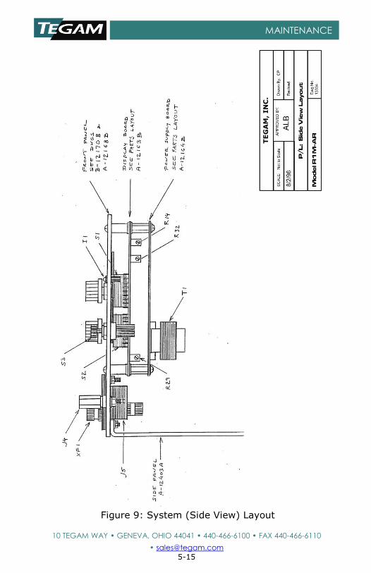
Figure 9: System (Side View) Layout
TE
GA
M,
IN
C.
Revised August, 2004
10 TEGAM WAY • GENEVA, OHIO 44041 • 440-466-6100 • FAX 440-466-6110
• [email protected] 5-16
MAINTENANCE
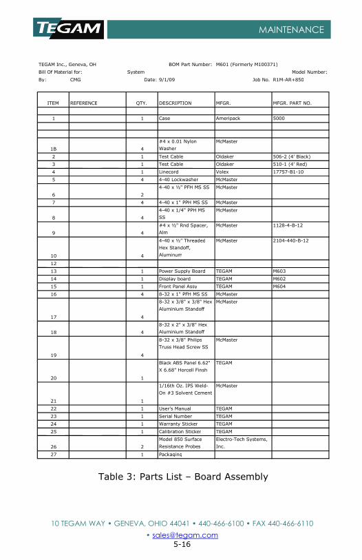
Table 3: Parts List – Board Assembly
TEGAM Inc., Geneva, OH BOM Part Number: M601 (Formerly M100371)
Bill Of Material for: System Model Number:
By: CMG Date: 9/1/09 Job No. R1M-AR+850
ITEM REFERENCE QTY. DESCRIPTION MFGR. MFGR. PART NO.
1 1 Case Ameripack 5000
1B 4
#4 x 0.01 Nylon
Washer
McMaster
2 1 Test Cable Oldaker 506-2 (4' Black)
3 1 Test Cable Oldaker 510-1 (4' Red)
4 1 Linecord Volex 17757-B1-10
5 4 4-40 Lockwasher McMaster
6 2
4-40 x ½" PFH MS SS McMaster
7 4 4-40 x 1" PPH MS SS McMaster
8 4
4-40 x 1/4" PPH MS
SS
McMaster
9 4
#4 x ½" Rnd Spacer,
Alm
McMaster 1128-4-B-12
10 4
4-40 x ½" Threaded
Hex Standoff,
Aluminum
McMaster 2104-440-B-12
12
13 1 Power Supply Board TEGAM M603
14 1 Display board TEGAM M602
15 1 Front Panel Assy TEGAM M604
16 4 8-32 x 1" PFH MS SS McMaster
17 4
8-32 x 3/8" x 3/8" Hex
Aluminium Standoff
McMaster
18 4
8-32 x 2" x 3/8" Hex
Aluminium Standoff
19 4
8-32 x 3/8" Philips
Truss Head Screw SS
McMaster
20 1
Black ABS Panel 6.62"
X 6.68" Horcell Finsh
TEGAM
21 1
1/16th Oz. IPS Weld-
On #3 Solvent Cement
McMaster
22 1 User's Manual TEGAM
23 1 Serial Number TEGAM
24 1 Warranty Sticker TEGAM
25 1 Calibration Sticker TEGAM
26 2
Model 850 Surface
Resistance Probes
Electro-Tech Systems,
Inc.
27 1 Packaging
Revised August, 2004
10 TEGAM WAY • GENEVA, OHIO 44041 • 440-466-6100 • FAX 440-466-6110
• [email protected] 5-17
MAINTENANCE
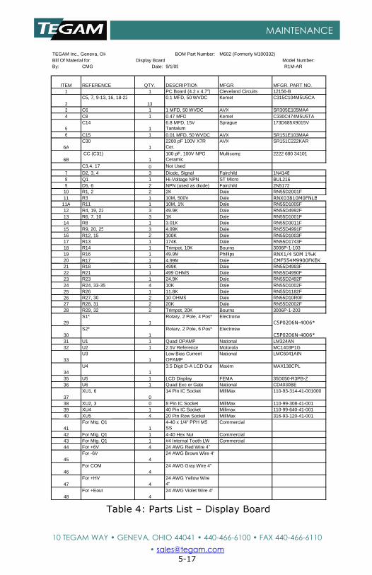
Table 4: Parts List – Display Board
TEGAM Inc., Geneva, OH OH
BOM Part Number: Number:
M602 (Formerly M100332) M100332) Bill Of Material for:
for: Display Board Board
Model Number: Number: By:
: CMG G
Date: :
9/1/09 9
R1M-AR AR
ITEM M
REFERENCE E
QTY. .
DESCRIPTION N
MFGR. .
MFGR. PART NO. NO. 1 1 PC Board (4.2 x 4.7")
4.7") Cleveland Circuits Circuits
12156-B B 2
C5, 7, 9-13, 16, 18-22 22 13
3
0.1 MFD, 50 WVDC WVDC
Kemet t
C315C104M5U5CA A 3 C6
6 1 1 MFD, 50 WVDC
WVDC AVX X
SR305E105MAA A 4 C8
8 1 0.47 MFD
MFD Kemet t
C330C474M5U5TA A 5
C14 4 1
6.8 MFD, 15V 15V Tantalum m
Sprague e
173D685X9015V V 6 C15
5 1 0.01 MFD, 50 WVDC
WVDC AVX X
SR151E103MAA A 6A
C30 0 1
2200 pF 100V X7R X7R Cer. .
AVX X
SR151C222KAR R
6B CC (C31) (C31) 1
100 pF, 100V NPO NPO Ceramic c
Multicomp p
2222 680 34101 34101 C3,4, 17
17 0 Not Used
Used 7 D2, 3, 4 4
3 Diode, Signal Signal
Fairchild d
1N4148 8 8 Q1
1 1 Hi-Voltage NPN
NPN ST Micro BUL216
6 9 D5, 6 6
2 NPN (used as diode) diode)
Fairchild d
2N5172 2 10 R1, 2
2 2 2K Dale
e RN55D2001F F 11 R3
3 1 10M, 500V
500V Dale e
RNX03810M0FNLB B
11A R11 1
1 10M, 1% 1%
Dale e
RN55D1005F F 12 R4, 19, 22
22 3 49.9K
K Dale e
RN55D4992F F 13 R6, 7, 10
10 3 1K Dale
e RN55D1001F F 14 R8
8 1 3.01K
K Dale e
RN55D3011F F 15 R9, 20, 25
25 3 4.99K
K Dale e
RN55D4991F F 16 R12, 15
15 2 100K
K Dale e
RN55D1003F F 17 R13
3 1 174K
K Dale e
RN55D1743F F 18 R14
4 1 Trimpot, 10K
10K Bourns s
3006P-1-103 103 19 R16
6 1 49.9M
M Phillips s
RNX1/4 50M 1%K 1%K
20 R17 7
1 4.99M M
Dale e
CMF554M9900FKEK K
21 R18 8
1 499K K
Dale e
RN55D4993F F 22 R21
1 1 499 OHMS
OHMS Dale e
RN55D4990F F 23 R23
3 1 24.9K
K Dale e
RN55D2492F F 24 R24, 33-35
35 4 10K
K Dale e
RN55D1002F F 25 R26
6 1 11.8K
K Dale e
RN55D1182F F 26 R27, 30
30 2 10 OHMS
OHMS Dale e
RN55D10R0F F 27 R28, 31
31 2 20K
K Dale RN55D2002F
28 R29, 32 2 Trimpot, 20K Bourns 3006P-1-203 29
S1* 1
Rotary, 2 Pole, 4 Pos* Electrosw C5P0206N-4006*
30 S2*
1 Rotary, 2 Pole, 6 Pos* Electrosw
C5P0206N-4006* 31 U1 1 Quad OPAMP National LM324AN 32 U2 1 2.5V Reference Motorola MC1403P1G 33
U3 1
Low Bias Current OPAMP
National LMC6041AIN
34 U4
1 3.5 Digit D-A LCD Out Maxim MAX138CPL
35 U5 1 LCD Display FEMA 35D050-R3PB-Z 36 U6 1 Quad Exc or Gate National CD4030BE 37
XU1, 6 0
14 Pin IC Socket MillMax 110-93-314-41-001000 38 XU2, 3 0 8 Pin IC Socket MillMax 110-99-308-41-001 39 XU4 1 40 Pin IC Socket Millmax 110-99-640-41-001 40 XU5 4 20 Pin Row Socket MillMax 316-93-120-41-001 41
For Mtg. Q1 1
4-40 x 1/4" PPH MS SS
Commercial 42 For Mtg. Q1 1 4-40 Hex Nut Commercial 43 For Mtg. Q1 1 #4 Internal Tooth LW Commercial 44 For +6V 4 24 AWG Red Wire 4" 45
For -6V 4
24 AWG Brown Wire 4"
46 For COM
4 24 AWG Gray Wire 4"
47 For +HV
4 24 AWG Yellow Wire 4"
48 For +Eout
4 24 AWG Violet Wire 4"
Revised August, 2004
10 TEGAM WAY • GENEVA, OHIO 44041 • 440-466-6100 • FAX 440-466-6110
• [email protected] 5-18
MAINTENANCE
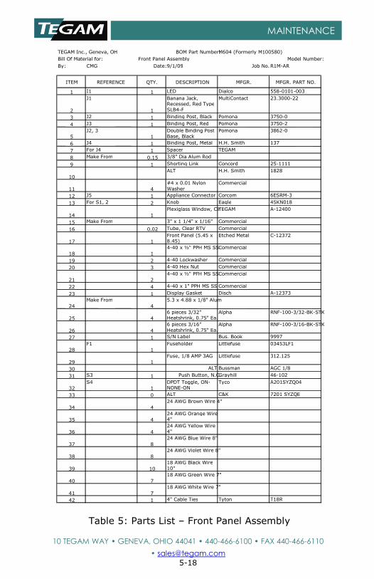
Table 5: Parts List – Front Panel Assembly
TEGAM Inc., Geneva, OH BOM Part Number: M604 (Formerly M100580)
Bill Of Material for: Front Panel Assembly Model Number:
By: CMG Date: 9/1/09 Job No. R1M-AR
ITEM REFERENCE QTY. DESCRIPTION MFGR. MFGR. PART NO.
1 I1 1 LED Dialco 558-0101-003
2
J1
1
Banana Jack, Recessed, Red Type SLB4-F
MultiContact 23.3000-22
3 J2 1 Binding Post, Black Pomona 3750-0
4 J3 1 Binding Post, Red Pomona 3750-2
5
J2, 3
1
Double Binding Post Base, Black
Pomona 3862-0
6 J4 1 Binding Post, Metal H.H. Smith 137
7 For J4 1 Spacer TEGAM
8 Make From 0.15 3/8" Dia Alum Rod
9 1 Shorting Link Concord 25-1111
10
ALT H.H. Smith 1828
11 4
#4 x 0.01 Nylon Washer
Commercial
12 J5 1 Appliance Connector Corcom 6ESRM-3
13 For S1, 2 2 Knob Eagle 45KN018
14 1
Plexiglass Window, Clr TEGAM A-12400
15 Make From 3" x 1 1/4" x 1/16" Commercial
16 0.02 Tube, Clear RTV Commercial
17 1
Front Panel (5.45 x 8.45)
Etched Metal C-12372
18 1
4-40 x ½" PPH MS SS Commercial
19 2 4-40 Lockwasher Commercial
20 3 4-40 Hex Nut Commercial
21 2
4-40 x ½" PFH MS SS Commercial
22 4 4-40 x 1" PPH MS SS Commercial
23 1 Display Gasket Disch A-12373
24
Make From
4
5.3 x 4.88 x 1/8" Alum
25 4
6 pieces 3/32" Heatshrink, 0.75" Ea.
Alpha RNF-100-3/32-BK-STK
26 4
6 pieces 3/16" Heatshrink, 0.75" Ea.
Alpha RNF-100-3/16-BK-STK
27 1 S/N Label Bus. Book 9997
28
F1
1
Fuseholder Littlefuse 03453LF1
29 1
Fuse, 1/8 AMP 3AG Littlefuse 312.125
30 ALT Bussman AGC 1/8
31 S3 1 Push Button, N.C. Grayhill 46-102
32
S4
1
DPDT Toggle, ON- NONE-ON
Tyco A201SYZQ04
33 0 ALT C&K 7201 SYZQE
34 4
24 AWG Brown Wire 4"
35 4
24 AWG Orange Wire 4"
36 4
24 AWG Yellow Wire 4"
37 8
24 AWG Blue Wire 8"
38 8
24 AWG Violet Wire 8"
39 10
18 AWG Black Wire 10"
40 7
18 AWG Green Wire 7"
41 7
18 AWG White Wire 7"
42 1 4" Cable Ties Tyton T18R
Revised August, 2004
10 TEGAM WAY • GENEVA, OHIO 44041 • 440-466-6100 • FAX 440-466-6110
• [email protected] 5-19
MAINTENANCE
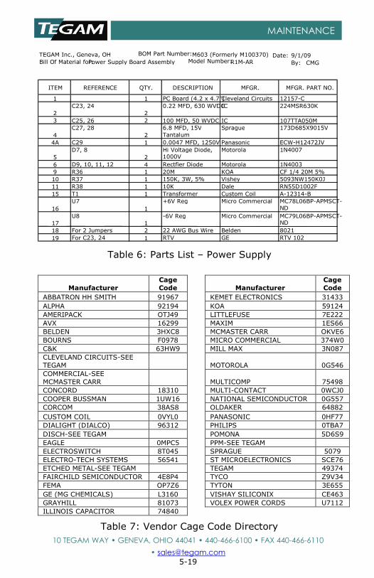
Table 6: Parts List – Power Supply
Manufacturer
Cage
Code
Manufacturer
Cage
Code
ABBATRON HH SMITH 91967
KEMET ELECTRONICS 31433
ALPHA 92194
KOA 59124
AMERIPACK OTJ49
LITTLEFUSE 7E222
AVX 16299
MAXIM 1ES66
BELDEN 3HXC8
MCMASTER CARR OKVE6
BOURNS F0978
MICRO COMMERCIAL 374W0
C&K 63HW9
MILL MAX 3N087
CLEVELAND CIRCUITS-SEE
TEGAM
MOTOROLA 0G546
COMMERCIAL-SEE
MCMASTER CARR
MULTICOMP 75498
CONCORD 18310
MULTI-CONTACT 0WCJ0
COOPER BUSSMAN 1UW16
NATIONAL SEMICONDUCTOR 0G557
CORCOM 38AS8
OLDAKER 64882
CUSTOM COIL 0VYL0
PANASONIC 0HF77
DIALIGHT (DIALCO) 96312
PHILIPS 0TBA7
DISCH-SEE TEGAM
POMONA 5D6S9
EAGLE 0MPC5
PPM-SEE TEGAM ELECTROSWITCH 8T045
SPRAGUE 5079
ELECTRO-TECH SYSTEMS 56541
ST MICROELECTRONICS SCE76
ETCHED METAL-SEE TEGAM
TEGAM 49374
FAIRCHILD SEMICONDUCTOR 4E8P4
TYCO Z9V34
FEMA OP7Z6
TYTON 3E655
GE (MG CHEMICALS) L3160
VISHAY SILICONIX CE463
GRAYHILL 81073
VOLEX POWER CORDS U7112
ILLINOIS CAPACITOR 74840
Table 7: Vendor Cage Code Directory
TEGAM Inc., Geneva, OH BOM Part Number: M603 (Formerly M100370)
Bill Of Material for: Power Supply Board Assembly Model Number: By: CMG
Date: 9/1/09 R1M-AR
ITEM REFERENCE QTY. DESCRIPTION MFGR. MFGR. PART NO.
1 1 PC Board (4.2 x 4.7") Cleveland Circuits 12157-C
2
C23, 24
2
0.22 MFD, 630 WVDC IC 224MSR630K
3 C25, 26 2 100 MFD, 50 WVDC IC 107TTA050M
4
C27, 28
2
6.8 MFD, 15V
Tantalum
Sprague 173D685X9015V
4A C29 1 0.0047 MFD, 1250V Panasonic ECW-H12472JV
5
D7, 8
2
Hi Voltage Diode, 1000V
Motorola 1N4007
6 D9, 10, 11, 12 4 Rectfier Diode Motorola 1N4003
9 R36 1 20M KOA CF 1/4 20M 5%
10 R37 1 150K, 3W, 5% Vishey 5093NW150K0J
11 R38 1 10K Dale RN55D1002F
15 T1 1 Transformer Custom Coil A-12314-B
16
U7
1
+6V Reg Micro Commercial MC78L06BP-APMSCT-
ND
17
U8
1
-6V Reg Micro Commercial MC79L06BP-APMSCT- ND
18 For 2 Jumpers 2 22 AWG Bus Wire Belden 8021
19 For C23, 24 1 RTV GE RTV 102
Revised August, 2004
10 TEGAM WAY • GENEVA, OHIO 44041 • 440-466-6100 • FAX 440-466-6110
• [email protected] 6-1
SERVICE INFORMATION
SECTION 6
SERVICE INFORMATION
Preparation for Calibration or Repair Service
Once you have verified that the cause for R1M-A malfunction
cannot be solved in the field and the need for repair and
calibration service arises, contact TEGAM customer service to
obtain an RMA, (Returned Material Authorization), number.
You can contact TEGAM customer service via the TEGAM
website, www.tegam.com or by calling 440.466.6100 (All
Locations) OR 800.666.1010 (United States Only).
The RMA number is unique to your instrument and will help
us identify you instrument and to address the particular
service request by you which is assigned to that RMA
number.
Of even importance, a detailed written description of the
problem should be attached to the instrument. Many times
repair turnaround is unnecessarily delayed due to a lack of
repair instructions or of a detailed description of the
problem.
This description should include information such as
measurement range, and other instrument settings, type of
components being tested, are the symptoms intermittent?,
conditions that may cause the symptoms, has anything
changed since the last time the instrument was used?, etc.
Any detailed information provided to our technicians will
assist them in identifying and correcting the problem in the
quickest possible manner. Use a copy of the Repair and
Calibration Service form provided on the next page.
Once this information is prepared and sent with the
instrument to our service department, we will do our part in
making sure that you receive the best possible customer
service and turnaround time possible.
Revised August, 2004
10 TEGAM WAY • GENEVA, OHIO 44041 • 440-466-6100 • FAX 440-466-6110
• [email protected] 6-2
SERVICE INFORMATION
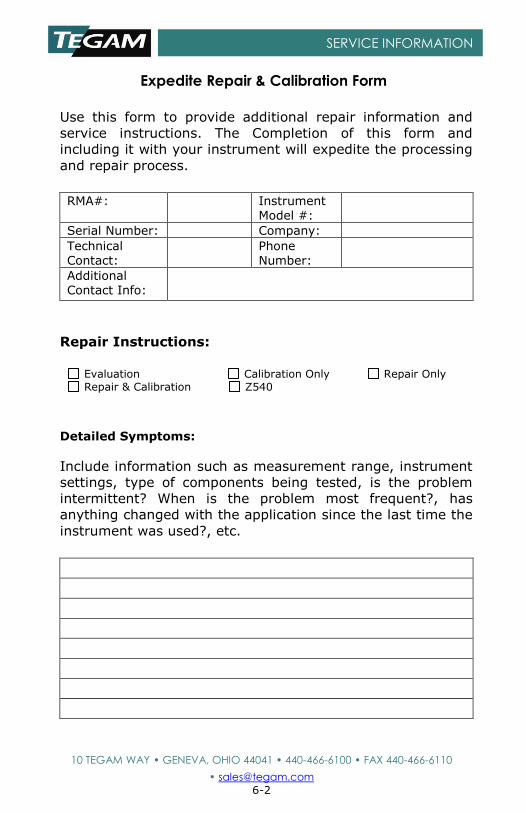
Expedite Repair & Calibration Form
Use this form to provide additional repair information and
service instructions. The Completion of this form and
including it with your instrument will expedite the processing
and repair process.
RMA#: Instrument
Model #:
Serial Number: Company:
Technical Contact:
Phone Number:
Additional Contact Info:
Repair Instructions:
Evaluation Calibration Only Repair Only Repair & Calibration Z540
Detailed Symptoms:
Include information such as measurement range, instrument
settings, type of components being tested, is the problem
intermittent? When is the problem most frequent?, has
anything changed with the application since the last time the
instrument was used?, etc.
Revised August, 2004
10 TEGAM WAY • GENEVA, OHIO 44041 • 440-466-6100 • FAX 440-466-6110
• [email protected] 6-3
SERVICE INFORMATION
Warranty
TEGAM, Inc. warrants this product to be free from defects in
material and workmanship for a period of one year from the
date of shipment. During this warranty period, if a product
proves to be defective, TEGAM Inc., at its option, will either
repair the defective product without charge for parts and
labor, or exchange any product that proves to be defective.
TEGAM, Inc. warrants the calibration of this product for a
period of one year from date of shipment. During this period,
TEGAM, Inc. will recalibrate any product, which does not
conform to the published accuracy specifications.
In order to exercise this warranty, TEGAM, Inc., must be
notified of the defective product before the expiration of the
warranty period. The customer shall be responsible for
packaging and shipping the product to the designated
TEGAM service center with shipping charges prepaid. TEGAM
Inc. shall pay for the return of the product to the customer if
the shipment is to a location within the country in which the
TEGAM service center is located. The customer shall be
responsible for paying all shipping, duties, taxes, and
additional costs if the product is transported to any other
locations. Repaired products are warranted for the remaining
balance of the original warranty, or 90 days, whichever
period is longer.

Revised August, 2004
10 TEGAM WAY • GENEVA, OHIO 44041 • 440-466-6100 • FAX 440-466-6110
• [email protected] 6-4
SERVICE INFORMATION
Warranty Limitations The TEGAM, Inc. warranty does not apply to defects resulting
from unauthorized modification or misuse of the product or
any part. This warranty does not apply to fuses, batteries, or
damage to the instrument caused by battery leakage.
The foregoing warranty of TEGAM is in lieu of all other
warranties, expressed or implied. TEGAM specifically
disclaims any implied warranties of merchantability or fitness
for a particular purpose. In no event will TEGAM be liable for
special or consequential damages. Purchaser’s sole and
exclusive remedy in the event any item fails to comply with
the foregoing express warranty of TEGAM shall be to return
the item to TEGAM; shipping charges prepaid and at the
option of TEGAM obtain a replacement item or a refund of
the purchase price.
Statement of Calibration
This instrument has been inspected and tested in accordance
with specifications published by TEGAM Inc. The accuracy
and calibration of this instrument are traceable to the
National Institute of Standards and Technology through
equipment, which is calibrated at planned intervals by
comparison to certified standards maintained in the
laboratories of TEGAM Inc.
Contact Information
TEGAM INC.
10, TEGAM WAY
GENEVA, OHIO 44041
CAGE Code: 49374 WEB: http://www.tegam.com