Embed Size (px)
Citation preview
19785,9 / 24.11.08
3
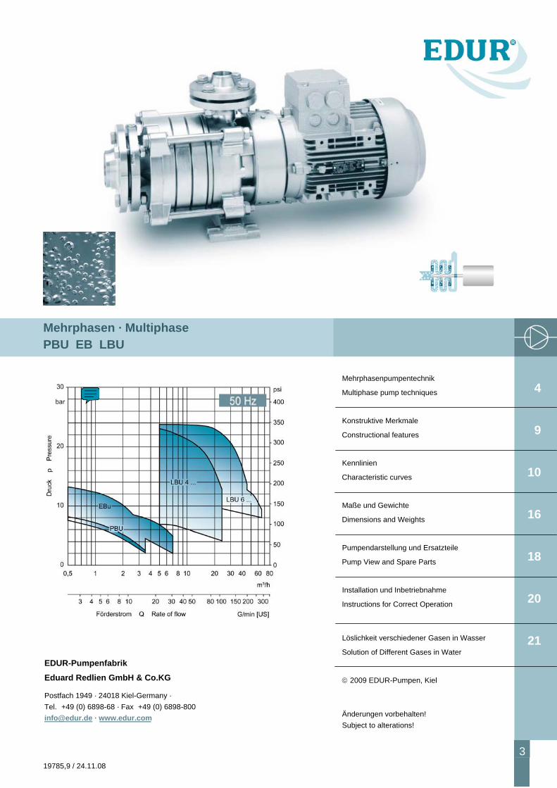
Mehrphasen · Multiphase PBU EB LBU
Mehrphasenpumpentechnik
Multiphase pump techniques
Konstruktive Merkmale
Constructional features
Kennlinien
Characteristic curves
Maße und Gewichte
Dimensions and Weights
Pumpendarstellung und Ersatzteile
Pump View and Spare Parts
Installation und Inbetriebnahme
Instructions for Correct Operation
Löslichkeit verschiedener Gasen in Wasser
Solution of Different Gases in Water
© 2009 EDUR-Pumpen, Kiel
Änderungen vorbehalten! Subject to alterations!
4
9
10
16
18
20
21
EDUR-Pumpenfabrik Eduard Redlien GmbH & Co.KG
Postfach 1949 · 24018 Kiel-Germany · Tel. +49 (0) 6898-68 · Fax +49 (0) 6898-800 [email protected] · www.edur.com
Mehrphasenpumpentechnik Multiphase Pump Techniques
4 19785,9 / 24.11.08
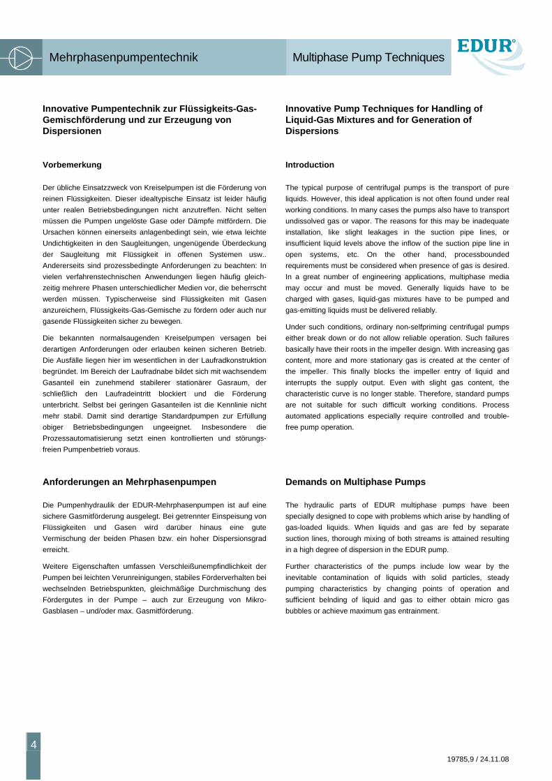
Innovative Pumpentechnik zur Flüssigkeits-Gas-Gemischförderung und zur Erzeugung von Dispersionen
Vorbemerkung
Der übliche Einsatzzweck von Kreiselpumpen ist die Förderung von reinen Flüssigkeiten. Dieser idealtypische Einsatz ist leider häufig unter realen Betriebsbedingungen nicht anzutreffen. Nicht selten müssen die Pumpen ungelöste Gase oder Dämpfe mitfördern. Die Ursachen können einerseits anlagenbedingt sein, wie etwa leichte Undichtigkeiten in den Saugleitungen, ungenügende Überdeckung der Saugleitung mit Flüssigkeit in offenen Systemen usw.. Andererseits sind prozessbedingte Anforderungen zu beachten: In vielen verfahrenstechnischen Anwendungen liegen häufig gleich-zeitig mehrere Phasen unterschiedlicher Medien vor, die beherrscht werden müssen. Typischerweise sind Flüssigkeiten mit Gasen anzureichern, Flüssigkeits-Gas-Gemische zu fördern oder auch nur gasende Flüssigkeiten sicher zu bewegen.
Die bekannten normalsaugenden Kreiselpumpen versagen bei derartigen Anforderungen oder erlauben keinen sicheren Betrieb. Die Ausfälle liegen hier im wesentlichen in der Laufradkonstruktion begründet. Im Bereich der Laufradnabe bildet sich mit wachsendem Gasanteil ein zunehmend stabilerer stationärer Gasraum, der schließlich den Laufradeintritt blockiert und die Förderung unterbricht. Selbst bei geringen Gasanteilen ist die Kennlinie nicht mehr stabil. Damit sind derartige Standardpumpen zur Erfüllung obiger Betriebsbedingungen ungeeignet. Insbesondere die Prozessautomatisierung setzt einen kontrollierten und störungs-freien Pumpenbetrieb voraus.
Anforderungen an Mehrphasenpumpen
Die Pumpenhydraulik der EDUR-Mehrphasenpumpen ist auf eine sichere Gasmitförderung ausgelegt. Bei getrennter Einspeisung von Flüssigkeiten und Gasen wird darüber hinaus eine gute Vermischung der beiden Phasen bzw. ein hoher Dispersionsgrad erreicht.
Weitere Eigenschaften umfassen Verschleißunempfindlichkeit der Pumpen bei leichten Verunreinigungen, stabiles Förderverhalten bei wechselnden Betriebspunkten, gleichmäßige Durchmischung des Fördergutes in der Pumpe – auch zur Erzeugung von Mikro-Gasblasen – und/oder max. Gasmitförderung.
Innovative Pump Techniques for Handling of Liquid-Gas Mixtures and for Generation of Dispersions
Introduction
The typical purpose of centrifugal pumps is the transport of pure liquids. However, this ideal application is not often found under real working conditions. In many cases the pumps also have to transport undissolved gas or vapor. The reasons for this may be inadequate installation, like slight leakages in the suction pipe lines, or insufficient liquid levels above the inflow of the suction pipe line in open systems, etc. On the other hand, processbounded requirements must be considered when presence of gas is desired. In a great number of engineering applications, multiphase media may occur and must be moved. Generally liquids have to be charged with gases, liquid-gas mixtures have to be pumped and gas-emitting liquids must be delivered reliably.
Under such conditions, ordinary non-selfpriming centrifugal pumps either break down or do not allow reliable operation. Such failures basically have their roots in the impeller design. With increasing gas content, more and more stationary gas is created at the center of the impeller. This finally blocks the impeller entry of liquid and interrupts the supply output. Even with slight gas content, the characteristic curve is no longer stable. Therefore, standard pumps are not suitable for such difficult working conditions. Process automated applications especially require controlled and trouble-free pump operation.
Demands on Multiphase Pumps
The hydraulic parts of EDUR multiphase pumps have been specially designed to cope with problems which arise by handling of gas-loaded liquids. When liquids and gas are fed by separate suction lines, thorough mixing of both streams is attained resulting in a high degree of dispersion in the EDUR pump.
Further characteristics of the pumps include low wear by the inevitable contamination of liquids with solid particles, steady pumping characteristics by changing points of operation and sufficient belnding of liquid and gas to either obtain micro gas bubbles or achieve maximum gas entrainment.
Mehrphasenpumpentechnik Multiphase Pump Techniques
19785,9 / 24.11.08
5
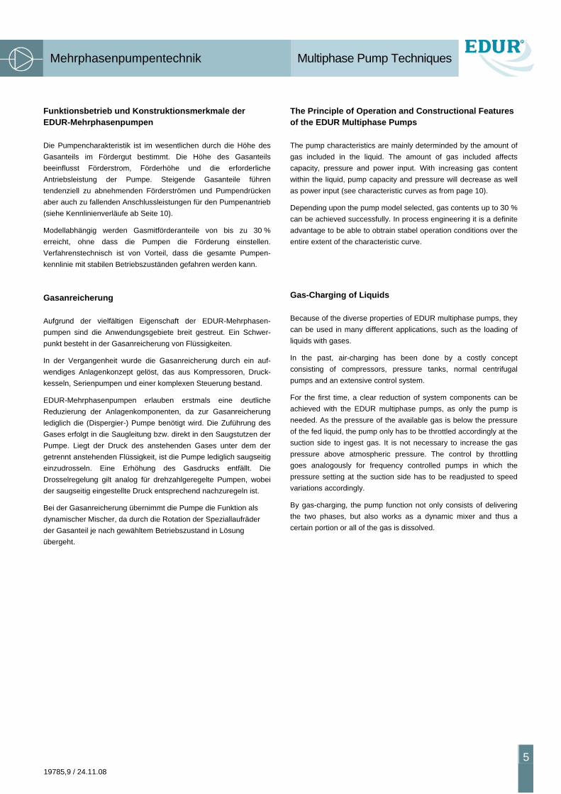
Funktionsbetrieb und Konstruktionsmerkmale der EDUR-Mehrphasenpumpen
Die Pumpencharakteristik ist im wesentlichen durch die Höhe des Gasanteils im Fördergut bestimmt. Die Höhe des Gasanteils beeinflusst Förderstrom, Förderhöhe und die erforderliche Antriebsleistung der Pumpe. Steigende Gasanteile führen tendenziell zu abnehmenden Förderströmen und Pumpendrücken aber auch zu fallenden Anschlussleistungen für den Pumpenantrieb (siehe Kennlinienverläufe ab Seite 10).
Modellabhängig werden Gasmitförderanteile von bis zu 30 % erreicht, ohne dass die Pumpen die Förderung einstellen. Verfahrenstechnisch ist von Vorteil, dass die gesamte Pumpen-kennlinie mit stabilen Betriebszuständen gefahren werden kann.
Gasanreicherung
Aufgrund der vielfältigen Eigenschaft der EDUR-Mehrphasen-pumpen sind die Anwendungsgebiete breit gestreut. Ein Schwer-punkt besteht in der Gasanreicherung von Flüssigkeiten.
In der Vergangenheit wurde die Gasanreicherung durch ein auf-wendiges Anlagenkonzept gelöst, das aus Kompressoren, Druck-kesseln, Serienpumpen und einer komplexen Steuerung bestand.
EDUR-Mehrphasenpumpen erlauben erstmals eine deutliche Reduzierung der Anlagenkomponenten, da zur Gasanreicherung lediglich die (Dispergier-) Pumpe benötigt wird. Die Zuführung des Gases erfolgt in die Saugleitung bzw. direkt in den Saugstutzen der Pumpe. Liegt der Druck des anstehenden Gases unter dem der getrennt anstehenden Flüssigkeit, ist die Pumpe lediglich saugseitig einzudrosseln. Eine Erhöhung des Gasdrucks entfällt. Die Drosselregelung gilt analog für drehzahlgeregelte Pumpen, wobei der saugseitig eingestellte Druck entsprechend nachzuregeln ist.
Bei der Gasanreicherung übernimmt die Pumpe die Funktion als dynamischer Mischer, da durch die Rotation der Speziallaufräder der Gasanteil je nach gewähltem Betriebszustand in Lösung übergeht.
The Principle of Operation and Constructional Features of the EDUR Multiphase Pumps
The pump characteristics are mainly determinded by the amount of gas included in the liquid. The amount of gas included affects capacity, pressure and power input. With increasing gas content within the liquid, pump capacity and pressure will decrease as well as power input (see characteristic curves as from page 10).
Depending upon the pump model selected, gas contents up to 30 % can be achieved successfully. In process engineering it is a definite advantage to be able to obtrain stabel operation conditions over the entire extent of the characteristic curve.
Gas-Charging of Liquids
Because of the diverse properties of EDUR multiphase pumps, they can be used in many different applications, such as the loading of liquids with gases.
In the past, air-charging has been done by a costly concept consisting of compressors, pressure tanks, normal centrifugal pumps and an extensive control system.
For the first time, a clear reduction of system components can be achieved with the EDUR multiphase pumps, as only the pump is needed. As the pressure of the available gas is below the pressure of the fed liquid, the pump only has to be throttled accordingly at the suction side to ingest gas. It is not necessary to increase the gas pressure above atmospheric pressure. The control by throttling goes analogously for frequency controlled pumps in which the pressure setting at the suction side has to be readjusted to speed variations accordingly.
By gas-charging, the pump function not only consists of delivering the two phases, but also works as a dynamic mixer and thus a certain portion or all of the gas is dissolved.
Mehrphasenpumpentechnik Multiphase Pump Techniques
6 19785,9 / 24.11.08
Anwendungen
Druckentspannungsflotation zur Abwasseraufbereitung und Wertstoffrückgewinnung
Abwässer oder Emulsionen werden durch Eintrag atmosphären-seitig vorhandener Luft oder mit anderen Gasen behandelt.
Begasungsflotation
Wasser oder Abwasser werden mit Luft oder Sauerstoff angereichert.
Neutralisation
Waschlaugen werden mit Kohlendioxid neutralisiert.
Trinkwasseraufbereitung
Belüftung von Rohwasser zur Oxidation von Eisen und Mangan in Wasserwerken.
Denitrifikation von Abwässern
Nitrate werden mit Hilfe von Sauerstoff aus vorgereinigten Abwässern entfernt.
usw.
In Abhängigkeit von den verschiedenen Anwendungen kommen die unterschiedlichsten Gase mit ihren spezifischen Eigenschaften zum Einsatz. Für die korrekte Pumpenauslegung ist die Löslichkeit des Gases in der betrachteten Flüssigkeit von herausragender Bedeutung. So liegt etwa die Löslichkeit und damit die Höhe des Gaseintrages von Luft oder Sauerstoff weit unter den Werten von Kohlendioxid (siehe Anhang).
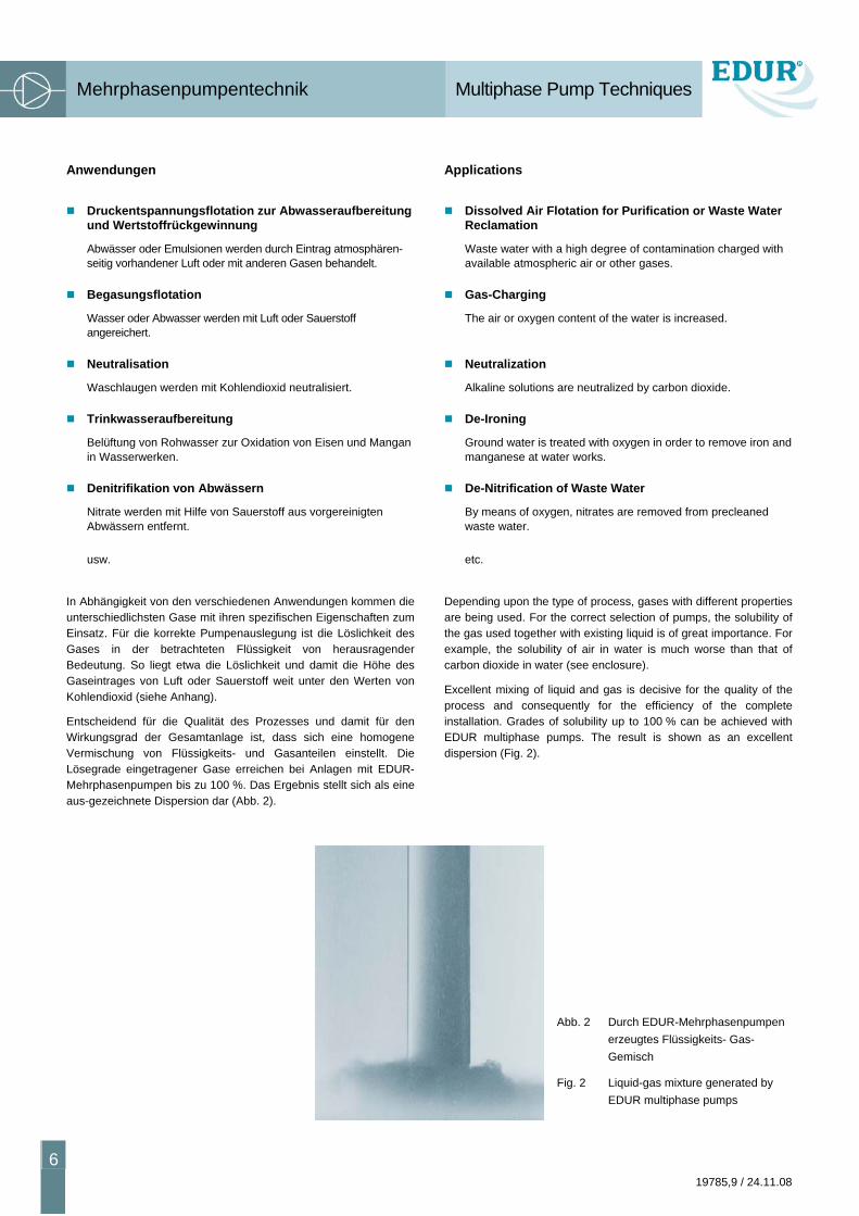
Entscheidend für die Qualität des Prozesses und damit für den Wirkungsgrad der Gesamtanlage ist, dass sich eine homogene Vermischung von Flüssigkeits- und Gasanteilen einstellt. Die Lösegrade eingetragener Gase erreichen bei Anlagen mit EDUR-Mehrphasenpumpen bis zu 100 %. Das Ergebnis stellt sich als eine aus-gezeichnete Dispersion dar (Abb. 2).
Applications
Dissolved Air Flotation for Purification or Waste Water Reclamation
Waste water with a high degree of contamination charged with available atmospheric air or other gases.
Gas-Charging
The air or oxygen content of the water is increased.
Neutralization
Alkaline solutions are neutralized by carbon dioxide.
De-Ironing
Ground water is treated with oxygen in order to remove iron and manganese at water works.
De-Nitrification of Waste Water
By means of oxygen, nitrates are removed from precleaned waste water.
etc.
Depending upon the type of process, gases with different properties are being used. For the correct selection of pumps, the solubility of the gas used together with existing liquid is of great importance. For example, the solubility of air in water is much worse than that of carbon dioxide in water (see enclosure).
Excellent mixing of liquid and gas is decisive for the quality of the process and consequently for the efficiency of the complete installation. Grades of solubility up to 100 % can be achieved with EDUR multiphase pumps. The result is shown as an excellent dispersion (Fig. 2).
Abb. 2 Durch EDUR-Mehrphasenpumpen erzeugtes Flüssigkeits- Gas-Gemisch
Fig. 2 Liquid-gas mixture generated by EDUR multiphase pumps
Mehrphasenpumpentechnik Multiphase Pump Techniques
19785,9 / 24.11.08
7
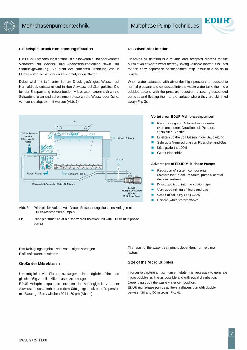
Fallbeispiel Druck-Entspannungsflotation
Die Druck-Entspannungsflotation ist ein bewährtes und anerkanntes Verfahren zur Wasser- und Abwasseraufbereitung sowie zur Stoffrückgewinnung. Sie dient der einfachen Trennung von in Flüssigkeiten schwebenden bzw. emulgierten Stoffen.
Dabei wird mit Luft unter hohem Druck gesättigtes Wasser auf Normaldruck entspannt und in den Abwasserbehälter geleitet. Die bei der Entspannung freiwerdenden Mikroblasen lagern sich an die Schwebstoffe an und schwemmen diese an die Wasseroberfläche, von der sie abgeskimmt werden (Abb. 3).
Das Reinigungsergebnis wird von einigen wichtigen Einflussfaktoren bestimmt:
Größe der Mikroblasen
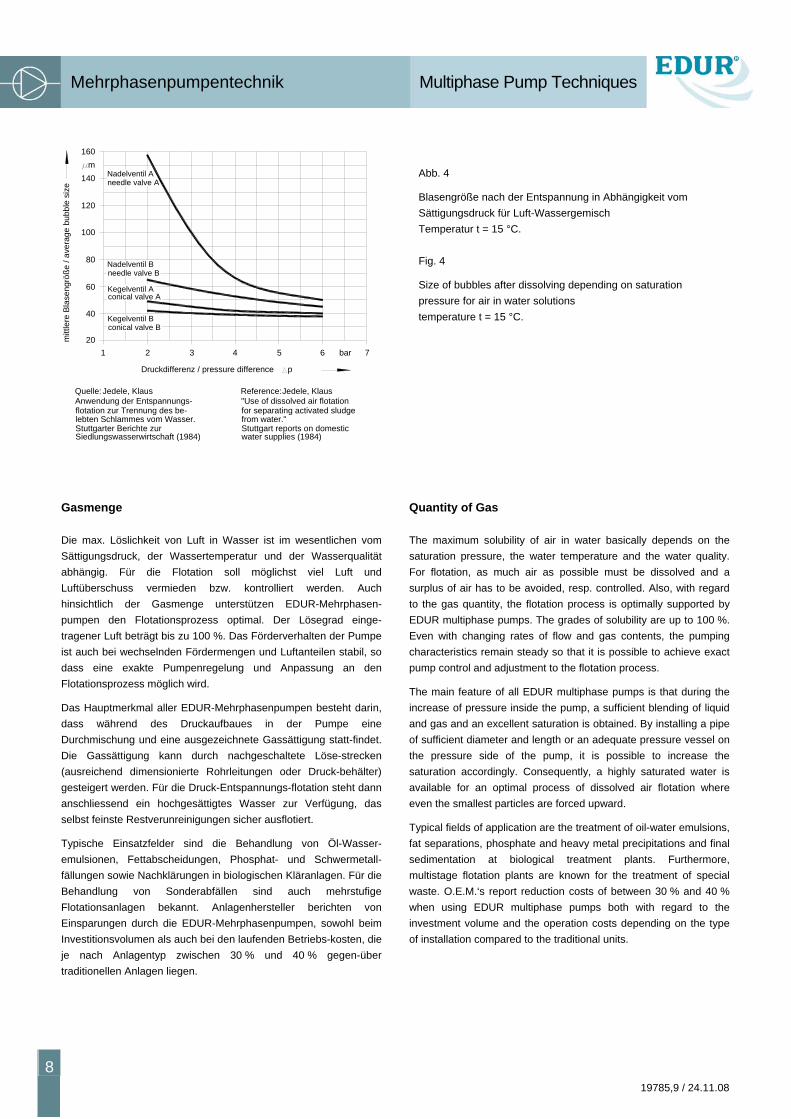
Um möglichst viel Flotat einzufangen, sind möglichst feine und gleichmäßig verteilte Mikroblasen zu erzeugen. EDUR-Mehrphasenpumpen erzielen in Abhängigkeit von der Abwasserbeschaffenheit und dem Sättigungsdruck eine Dispersion mit Blasengrößen zwischen 30 bis 50 μm (Abb. 4).
Dissolved Air Flotation
Dissolved air flotation is a reliable and accepted process for the purification of waste water thereby saving valuable matter. It is used for the easy separation of suspended resp. emulsifield solids in liquids.
When water saturated with air under high pressure is reduced to normal pressure and conducted into the waste water tank, the micro bubbles ascend with the pressure reduction, attracting suspended particles and floating them to the surface where they are skimmed away (Fig. 3).
Vorteile von EDUR-Mehrphasenpumpen
Reduzierung von Anlagenkomponenten (Kompressoren, Druckkessel, Pumpen, Steuerung, Ventile)
Direkte Zugabe von Gasen in die Saugleitung Sehr gute Vermischung von Flüssigkeit und Gas Lösegrade bis 100% Gutes Blasenbild
Advantages of EDUR-Multiphase Pumps
Reduction of system components (compressor, pressure tanks, pumps, control devices, valves)
Direct gas input into the suction pipe Very good mixing of liquid and gas Grade of solubility up to 100% Perfect „white water“ effects
The result of the water treatment is dependent from two main factors:
Size of the Micro Bubbles
In order to capture a maximum of flotate, it is necessary to generate micro bubbles as fine as possible and with equal distribution. Depending upon the waste water composition. EDUR multiphase pumps achieve a dispersipon with dubble between 30 and 50 microns (Fig. 4).
Abb. 3 Prinzipieller Aufbau von Druck- Entspannungsflotations-Anlagen mit EDUR-Mehrphasenpumpen.
Fig. 3 Principle structure of a dissolved air flotation unit with EDUR multiphase pumps.
Mehrphasenpumpentechnik Multiphase Pump Techniques
8 19785,9 / 24.11.08
Gasmenge
Die max. Löslichkeit von Luft in Wasser ist im wesentlichen vom Sättigungsdruck, der Wassertemperatur und der Wasserqualität abhängig. Für die Flotation soll möglichst viel Luft und Luftüberschuss vermieden bzw. kontrolliert werden. Auch hinsichtlich der Gasmenge unterstützen EDUR-Mehrphasen-pumpen den Flotationsprozess optimal. Der Lösegrad einge-tragener Luft beträgt bis zu 100 %. Das Förderverhalten der Pumpe ist auch bei wechselnden Fördermengen und Luftanteilen stabil, so dass eine exakte Pumpenregelung und Anpassung an den Flotationsprozess möglich wird.
Das Hauptmerkmal aller EDUR-Mehrphasenpumpen besteht darin, dass während des Druckaufbaues in der Pumpe eine Durchmischung und eine ausgezeichnete Gassättigung statt-findet. Die Gassättigung kann durch nachgeschaltete Löse-strecken (ausreichend dimensionierte Rohrleitungen oder Druck-behälter) gesteigert werden. Für die Druck-Entspannungs-flotation steht dann anschliessend ein hochgesättigtes Wasser zur Verfügung, das selbst feinste Restverunreinigungen sicher ausflotiert.
Typische Einsatzfelder sind die Behandlung von Öl-Wasser-emulsionen, Fettabscheidungen, Phosphat- und Schwermetall-fällungen sowie Nachklärungen in biologischen Kläranlagen. Für die Behandlung von Sonderabfällen sind auch mehrstufige Flotationsanlagen bekannt. Anlagenhersteller berichten von Einsparungen durch die EDUR-Mehrphasenpumpen, sowohl beim Investitionsvolumen als auch bei den laufenden Betriebs-kosten, die je nach Anlagentyp zwischen 30 % und 40 % gegen-über traditionellen Anlagen liegen.
Abb. 4
Blasengröße nach der Entspannung in Abhängigkeit vom Sättigungsdruck für Luft-Wassergemisch Temperatur t = 15 °C.
Fig. 4
Size of bubbles after dissolving depending on saturation pressure for air in water solutions temperature t = 15 °C.
Quantity of Gas
The maximum solubility of air in water basically depends on the saturation pressure, the water temperature and the water quality. For flotation, as much air as possible must be dissolved and a surplus of air has to be avoided, resp. controlled. Also, with regard to the gas quantity, the flotation process is optimally supported by EDUR multiphase pumps. The grades of solubility are up to 100 %. Even with changing rates of flow and gas contents, the pumping characteristics remain steady so that it is possible to achieve exact pump control and adjustment to the flotation process.
The main feature of all EDUR multiphase pumps is that during the increase of pressure inside the pump, a sufficient blending of liquid and gas and an excellent saturation is obtained. By installing a pipe of sufficient diameter and length or an adequate pressure vessel on the pressure side of the pump, it is possible to increase the saturation accordingly. Consequently, a highly saturated water is available for an optimal process of dissolved air flotation where even the smallest particles are forced upward.
Typical fields of application are the treatment of oil-water emulsions, fat separations, phosphate and heavy metal precipitations and final sedimentation at biological treatment plants. Furthermore, multistage flotation plants are known for the treatment of special waste. O.E.M.‘s report reduction costs of between 30 % and 40 % when using EDUR multiphase pumps both with regard to the investment volume and the operation costs depending on the type of installation compared to the traditional units.
Druckdifferenz / pressure difference p
4
mitt
lere
Bla
seng
röße
/ av
erag
e bu
bble
siz
e
conical valve BKegelventil B
conical valve AKegelventil A
needle valve BNadelventil B
201 2
60
40
80
3
needle valve ANadelventil A
160
120
100
m140
5 bar6 7
Quelle:Anwendung der Entspannungs-flotation zur Trennung des be-lebten Schlammes vom Wasser.Stuttgarter Berichte zurSiedlungswasserwirtschaft (1984)
Jedele, Klaus
for separating activated sludge"Use of dissolved air flotation
Jedele, Klaus
water supplies (1984)Stuttgart reports on domesticfrom water."
Reference:
Konstruktive Merkmale Constructional Features
19785,9 / 24.11.08
9
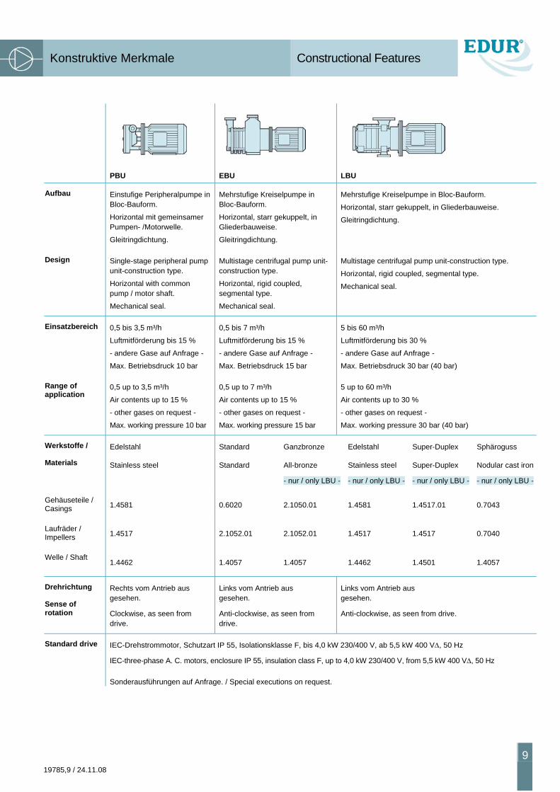
PBU EBU LBU
Aufbau Einstufige Peripheralpumpe in Bloc-Bauform.
Horizontal mit gemeinsamer Pumpen- /Motorwelle.
Gleitringdichtung.
Mehrstufige Kreiselpumpe in Bloc-Bauform.
Horizontal, starr gekuppelt, in Gliederbauweise.
Gleitringdichtung.
Mehrstufige Kreiselpumpe in Bloc-Bauform.
Horizontal, starr gekuppelt, in Gliederbauweise.
Gleitringdichtung.
Design Single-stage peripheral pump unit-construction type.
Horizontal with common pump / motor shaft.
Mechanical seal.
Multistage centrifugal pump unit-construction type.
Horizontal, rigid coupled, segmental type.
Mechanical seal.
Multistage centrifugal pump unit-construction type.
Horizontal, rigid coupled, segmental type.
Mechanical seal.
Einsatzbereich 0,5 bis 3,5 m³/h
Luftmitförderung bis 15 %
- andere Gase auf Anfrage -
Max. Betriebsdruck 10 bar
0,5 bis 7 m³/h
Luftmitförderung bis 15 %
- andere Gase auf Anfrage -
Max. Betriebsdruck 15 bar
5 bis 60 m³/h
Luftmitförderung bis 30 %
- andere Gase auf Anfrage -
Max. Betriebsdruck 30 bar (40 bar)
Range of application
0,5 up to 3,5 m³/h
Air contents up to 15 %
- other gases on request -
Max. working pressure 10 bar
0,5 up to 7 m³/h
Air contents up to 15 %
- other gases on request -
Max. working pressure 15 bar
5 up to 60 m³/h
Air contents up to 30 %
- other gases on request -
Max. working pressure 30 bar (40 bar)
Werkstoffe /
Materials
Edelstahl
Stainless steel
Standard
Standard
Ganzbronze
All-bronze
- nur / only LBU -
Edelstahl
Stainless steel
- nur / only LBU -
Super-Duplex
Super-Duplex
- nur / only LBU -
Sphäroguss
Nodular cast iron
- nur / only LBU -
Gehäuseteile / Casings 1.4581 0.6020 2.1050.01 1.4581 1.4517.01 0.7043
Laufräder / Impellers 1.4517 2.1052.01 2.1052.01 1.4517 1.4517 0.7040
Welle / Shaft 1.4462 1.4057 1.4057 1.4462 1.4501 1.4057
Drehrichtung
Sense of rotation
Rechts vom Antrieb aus gesehen.
Clockwise, as seen from drive.
Links vom Antrieb aus gesehen.
Anti-clockwise, as seen from drive.
Links vom Antrieb aus gesehen.
Anti-clockwise, as seen from drive.
Standard drive IEC-Drehstrommotor, Schutzart IP 55, Isolationsklasse F, bis 4,0 kW 230/400 V, ab 5,5 kW 400 VΔ, 50 Hz
IEC-three-phase A. C. motors, enclosure IP 55, insulation class F, up to 4,0 kW 230/400 V, from 5,5 kW 400 VΔ, 50 Hz
Sonderausführungen auf Anfrage. / Special executions on request.

Kennlinien Characteristic Curves
10 19785,9 / 24.11.08
Kennlinien für Fördergut mit einer Dichte ρ = 1 kg/dm³ · Viskosität ν = 1 mm²/s · Temperatur t = 20 °C und unterschiedlichen Gasanteilen (in %)
Characteristic curves for pumped media with a density ρ = 1 kg/dm³ · Viscosity ν = 1 mm²/s · Temperature t = 20 °C and different gas contents (in %)
0
2
4
m8
G/min[US]
m³/hQ
PBU 201 E10
psi
6
0Q m³/h
0
ftNPSH
Q m³/h0
5 %
10 %15 %
80
60
40
0
20
100
8,0
4,0
6,0
5,0
0
2,0
1,0
3,0
7,0
9,0
10,0
bar
120
140
0 0,5 1,0 1,5 2,0 2,5 3,0 3,5
100 2 4 6 8 12 14
0,5 1,51,0 2,0 2,5 3,0 3,5
10
20
5
15
0,5 1,51,0 2,0 2,5 3,0 3,50,5
2,0
kW
1,5
1,0
5 %
0,5
15 %10 %
2,0
kW
1,5
1,0
Q m³/h
0,6
0
1,0
0,8
1,00,5 1,5
kWP1,4
1,2
00
1,00,5 1,5
m
2
1
3
0
4
42 6
15 %
m³/h2,52,0
Q 3,0
0,6
3,5
0,8
1,05 %
m³/h
10 %
2,52,0Q
3,0
kW
1,2
1,4
3,50
14108 12
12
4
8ft
[US]G/min
7,0
1,0
00
3,0
2,0
1,00,5 1,5
5,0
4,0
6,0
EB3u8,0
barp
100
10 %
15 %
2,52,0 3,0
20
3,50
5 %
40
60
80
psi
0 %
0 %
0 % 0 %
0 %
0 %
0,40,4
p
NPSH
P
p
NPSH
P
ca. 2900 1/minappx. 2900 rpm
ca. 2900 1/minappx. 2900 rpm
Kennlinien Characteristic Curves
19785,9 / 24.11.08
11
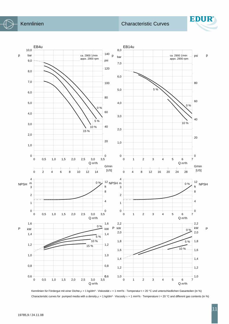
Kennlinien für Fördergut mit einer Dichte ρ = 1 kg/dm³ · Viskosität ν = 1 mm²/s · Temperatur t = 20 °C und unterschiedlichen Gasanteilen (in %)
Characteristic curves for pumped media with a density ρ = 1 kg/dm³ · Viscosity ν = 1 mm²/s · Temperature t = 20 °C and different gas contents (in %)
15 %
12
0,6
0,8
1,0
0,50 1,0 2,01,5 2,5
kW
1,2
1,4
1,6
0
m
2
1
3
4
0,50 1,0 2,01,5 2,5
20 4 86 10
4,0
0
1,0
3,0
2,0
5,0
6,0
7,0
8,0
0,50 1,0 2,01,5 2,5
10,0
9,0
bar
EB4u
Q m³/h
0,60
m³/h3,0
Q 3,5
0,8
1,0
kW
5 %10 %
15 % 1,2
1,4
Q m³/h3,0
1,6
3,50
12
4
8ft
14 [US]G/min
60
3,00
3,5
20
10 %
5 %
40
80
100
120
psi
140
P
NPSH
0 %
0 %
0 %
NPSH
p
P P
NPSH
pp
000 1 2 3 4
m³/h5
Q 6 7
EB14u
bar
2,0
1,0
3,0
4,0
5,0
6,0
7,0
8,0
5 %
0 %
20
10 %40
80
60
psi
[US]G/min
0 4 8 12 16 20 24 28
1
00
3
4
2
m
1 2 3 4
4
m³/h5
Q 6 7
0
0 %
8
12ft
1,00
1,2
1,4
1,6
2,2
1,8
2,0kW
10 %
1 2 3 4 m³/h
5Q
61,0
7
1,4
1,2
1,6
2,2
0 %
5 % 1,8
kW2,0
ca. 2900 1/minappx. 2900 rpm
ca. 2900 1/minappx. 2900 rpm
Kennlinien Characteristic Curves
12 19785,9 / 24.11.08
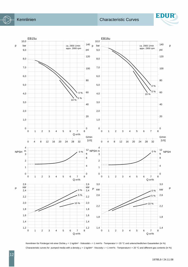
Kennlinien für Fördergut mit einer Dichte ρ = 1 kg/dm³ · Viskosität ν = 1 mm²/s · Temperatur t = 20 °C und unterschiedlichen Gasanteilen (in %)
Characteristic curves for pumped media with a density ρ = 1 kg/dm³ · Viscosity ν = 1 mm²/s · Temperature t = 20 °C and different gas contents (in %)
1,40
Q m³/h
3,0
m
00
1
2
Q m³/h
4
3
EB16u
1,4
8
3,0
0
4
NPSHft12
G/min[US]
P
0 %NPSH
p
P
p p
NPSH
P
000 1 2 3 4 5 6 7 8
1,0
2,0
4,0
3,0
7,0
5,0
6,0
8,0
9,0
bar
10,0
60
40
20
psi
80
100
120
140
280 4 8 2012 16 24 32
1 2 3 4 5 6 7 8
1 2 3 4 5 6 7 8
kWkW
2,62,6
2,22,2
1,81,8
0 %
5 %10 %
10 %
5 %
0 %
00
Q m³/h0 1 2 3 4 5 6 7 8
10 %
1,0
2,0
4,0
3,0
7,0
5,0
6,0
8,0
9,0
EB15u
bar
10,0
60
40
20
5 %
0 %
psi
80
100
120
140
280 4 8 2012 16 24
G/min
32 [US]
Q m³/h
1
00
1 2
2
m3
4
3 4 5 6
4
7 80
0 %
8ft
2,0
1,20
1,4
1,6
1,8
1 2 3 4 5 6
2,6kW
2,2
2,4
10 % 2,0
1,4
1,6
1,8
1,27 8
kW
2,2
2,4
2,6
0 %
5 %
Q m³/h
12
ca. 2900 1/minappx. 2900 rpm
ca. 2900 1/minappx. 2900 rpm
Kennlinien Characteristic Curves
19785,9 / 24.11.08
13
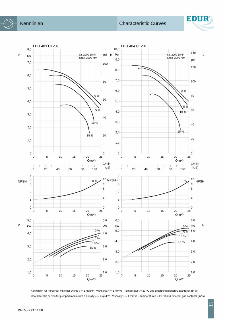
Kennlinien für Fördergut mit einer Dichte ρ = 1 kg/dm³ · Viskosität ν = 1 mm²/s · Temperatur t = 20 °C und unterschiedlichen Gasanteilen (in %)
Characteristic curves for pumped media with a density ρ = 1 kg/dm³ · Viscosity ν = 1 mm²/s · Temperature t = 20 °C and different gas contents (in %)
Q m³/h
10 %
m
00
1
2
5 %
Q m³/h
4
3
Q m³/h
8
0
4
NPSHft12
G/min[US]
P
0 %
0 %
NPSH
p
P
0 0200 5 10 15 25
15 %
LBU 404 C120L
10 %
5 %
0 %
psi
60
20
40
80
6,0
7,0
bar
8,0
3,0
4,0
5,0
1,0
2,0
100
10,0
9,0
140
120
5 10 15 20 25
1,00
3,0
2,0
6,0
5,0
4,0
kW
3,0
2,0
1,0
4,0
6,0
5,0
kW
5 10 15 20 25
15 %
200 40 60 80 100
p
NPSH
P
0 0
Q m³/h200 5 10 15 25
15 %
bar
2,0
1,0
3,0
4,0
5,0
6,0
7,0
LBU 403 C120L8,0
20
40
10 %
5 %
60
80
100
0 %
psi
0 20 6040 80
G/min
100 [US]
m³/hQ 20
1
00
5
2
m3
4
10 15
4
250
120 %
8ft
m³/hQ 20
1,00
3,0
2,0
5 10 15
5,0
4,0
kW
10 %3,0
1,0
2,0
25
15 %
5,0
4,0
kW
5 %
0 %
pca. 2900 1/minappx. 2900 rpm
ca. 2900 1/minappx. 2900 rpm
Kennlinien Characteristic Curves
14 19785,9 / 24.11.08
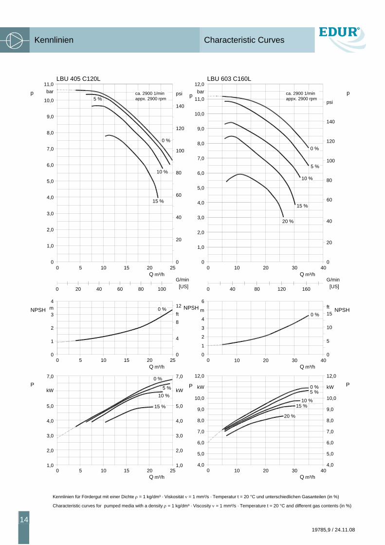
Kennlinien für Fördergut mit einer Dichte ρ = 1 kg/dm³ · Viskosität ν = 1 mm²/s · Temperatur t = 20 °C und unterschiedlichen Gasanteilen (in %)
Characteristic curves for pumped media with a density ρ = 1 kg/dm³ · Viscosity ν = 1 mm²/s · Temperature t = 20 °C and different gas contents (in %)
4,00
0
12,0
0
0
6
00
LBU 603 C160L12,0
Q m³/h
15 %
m³/hQ
4,0
10 %
m³/hQ
5 %
12,0
0
[US]G/min
10 %
15 %
0
5 %
P
NPSH
p
0 %
0 %
0 %
p p
NPSHNPSH
P P
10 20 30 40
11,0
10,0
9,0
8,0
7,0
6,0
5,0
4,0
3,0
2,0
1,0
bar
100
80
60
40
20
120
140
psi
40 80 120 160
20 %
10 20 30 40
m
4
3
2
15
10
15ft
kWkW
10,010,0
8,08,0
6,06,0
10 20 30 40
20 %
5,0
7,0
9,0
5,0
7,0
9,0
0 0
Q m³/h200 5 10 15 25
2,0
1,0
4,0
3,0
60
40
20
15 %
5 %
5,0
7,0
6,0
10,0
9,0
8,0
LBU 405 C120L
bar11,0
140
120
100
80
0 %
10 %
psi
0 20 6040 80 100
m³/hQ 20
1
00
5
2
m3
4
10 15
4
250
120 %
8ft
m³/hQ 20
1,00
2,0
3,0
4,0
5 10 15
7,0
5,0
kW
2,0
3,0
4,0
1,025
5,0
kW
7,0
5 %
15 %
10 %
0 %
G/min[US]
ca. 2900 1/minappx. 2900 rpm
ca. 2900 1/minappx. 2900 rpm
Kennlinien Characteristic Curves
19785,9 / 24.11.08
15
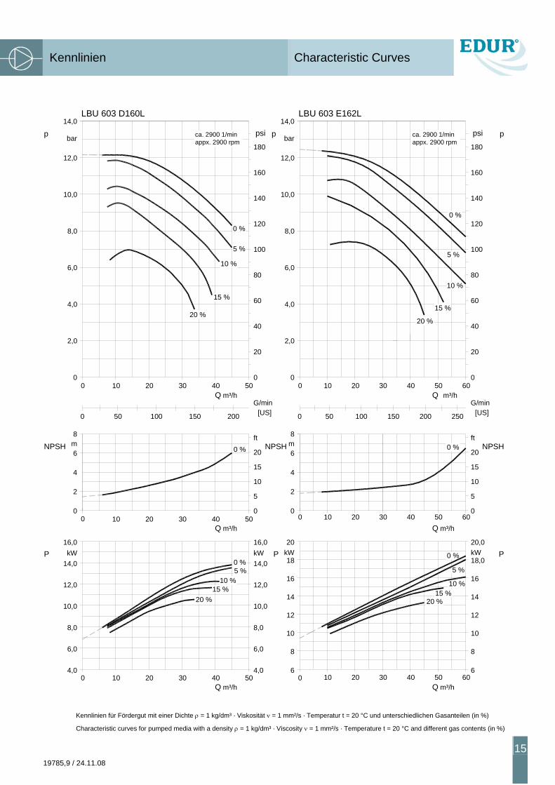
Kennlinien für Fördergut mit einer Dichte ρ = 1 kg/dm³ · Viskosität ν = 1 mm²/s · Temperatur t = 20 °C und unterschiedlichen Gasanteilen (in %)
Characteristic curves for pumped media with a density ρ = 1 kg/dm³ · Viscosity ν = 1 mm²/s · Temperature t = 20 °C and different gas contents (in %)
10
14
2,0
8,0
14,0
10,0
12,0
6,0
4,0
bar
18kW20
16
12
6
200100 150 250 [US]500
200 10 30 40
10
14
12
m³/hQ 50 60
6
20,0
18,0kW
16
m³/hQ
200
0 10 30 40
LBU 603 E162L
120
100
G/min
40
m³/hQ 50 60
0
20
15 %
80
60
psi
180
140
160
20 %
10 %
5 %
0 %
8 8
20 %15 %
10 %
5 %
0 %
00
2
4
8
6m
10 20 300
40 50 60
5
15
10
ft
200 %
p
NPSH
P
40
40Q m³/h
15 %
Q m³/h
20 %
4,00
6,0
8,0
10,0
10 20 30
2
16,0kW
12,0
14,0
00
10
4
m6
8
20 30
6,0
8,0
10,0
4,050
kW
12,0
14,0
16,0
0 %5 %
10 %
500
5
P
10
20
15
0 %ft
NPSH
[US]
040 m³/hQ
20 30
G/min
50
15 %
20 %
60
80
20
40
00 10
bar
2,0
6,0
4,0
10,0
8,0
12,0
LBU 603 D160L14,0
10 %
180
160
140
100
1200 %
5 %
psi p p
NPSH
P
ca. 2900 1/minappx. 2900 rpm
ca. 2900 1/minappx. 2900 rpm
0 50 150100 200
Maßtabellen Dimension Tables
16 19785,9 / 24.11.08
PBU
Nettogewichte Net weights
Pumpenmodell Pump model
EBu
ca. 2900 1/min Mot
orle
istu
ng
Mot
or p
ower
out
put
Mot
or B
augr
öße
Mot
or fr
ame
size
Mot
or- B
aufo
rm
Stru
ctur
al fo
rm
Drehstrommotor Threephase induction motor
Pumpenabmessungen Dimensions of pump
mit
Mot
or
with
mot
or
ohne
Mot
or
with
out M
otor
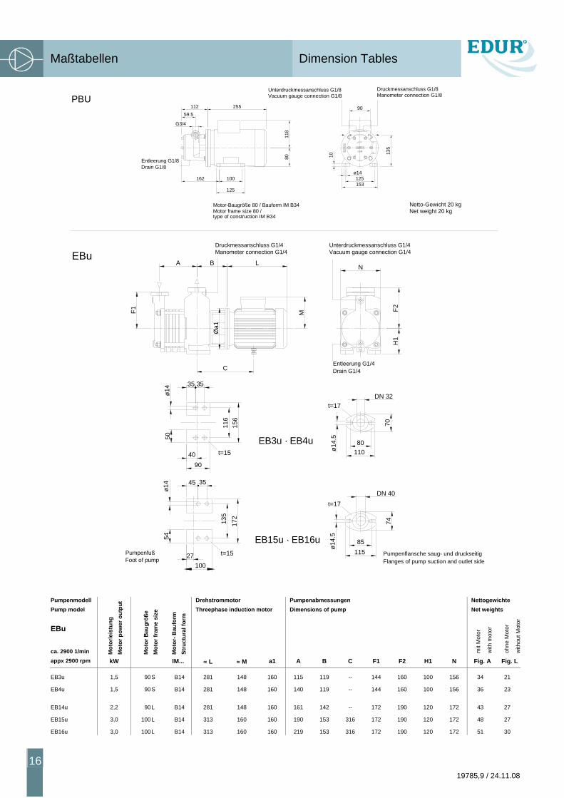
appx 2900 rpm kW IM... ≈ L ≈ M a1 A B C F1 F2 H1 N Fig. A Fig. L
EB3u 1,5 90S B14 281 148 160 115 119 -- 144 160 100 156 34 21
EB4u 1,5 90S B14 281 148 160 140 119 -- 144 160 100 156 36 23
EB14u 2,2 90L B14 281 148 160 161 142 -- 172 190 120 172 43 27
EB15u 3,0 100L B14 313 160 160 190 153 316 172 190 120 172 48 27
EB16u 3,0 100L B14 313 160 160 219 153 316 172 190 120 172 51 30
35
45
Unterdruckmessanschluss G1/4Vacuum gauge connection G1/4
90
EBu
ø14.
5ø1
4.5
DN 40
74
80110
11585
70DN 32
116
156
35
ø14
50
40
ø14
54
135
172
27100
35
A B L
F1 F2H
1
M
Entleerung G1/4Drain G1/4
Druckmessanschluss G1/4Manometer connection G1/4
PumpenfußFoot of pump
Pumpenflansche saug- und druckseitigFlanges of pump suction and outlet side
EB3u · EB4u
EB15u · EB16u
t=15
t=15
t=17
t=17
N
Øa1
C
11259.5
255
Motor-Baugröße 80 / Bauform IM B34Motor frame size 80 /type of construction IM B34
G3/4
162
118
80
100
Entleerung G1/8Drain G1/8
153
ø14125
10
90
135
Unterdruckmessanschluss G1/8Vacuum gauge connection G1/8
Druckmessanschluss G1/8Manometer connection G1/8
125
Netto-Gewicht 20 kgNet weight 20 kg
Maßtabellen Dimension Tables
19785,9 / 24.11.08
17
Nettogewichte
Net weights
Pumpenmodell Pump model
LBU
ca. 2900 1/min Mot
orle
istu
ng
Mot
or p
ower
out
put
Mot
or- B
augr
öße
Mot
or fr
ame
size
Mot
or- B
aufo
rm
Stru
ctur
al fo
rm
Bauhöhen h Shaft heights h
Pumpe Pump
Drehstrommotor Threephase induction motor
Motorfuß Motor footing
* variabel je nach Motorfabrikat * variable depending on motor make
Kup
plun
g
Cou
plin
g
mit
Mot
or
with
mot
or
ohne
Mot
or
with
out M
otor
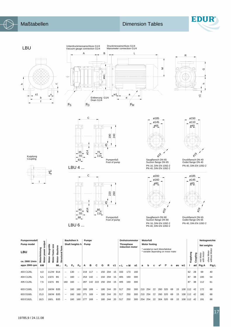
appx 2900 rpm kW IM... FS FD FM A B C G R c1 ≈ L ≈ M a1 a b c e* f* n øs w1 l ød Fig.A Fig.L
403 C120L 4,0 112 M B14 -- 130 -- 219 117 -- 150 204 15 333 173 160 62 28 69 40
404 C120L 5,5 132 S B5 -- 160 -- 253 142 -- 150 204 15 405 193 300 87 38 100 54
405 C120L 7,5 132 S B5 160 160 -- 287 142 222 150 204 15 405 193 300 87 38 112 61
603 C160L 11,0 160 M B35 -- 160 160 265 169 -- 180 244 20 517 250 300 210 254 22 260 320 69 15 108 112 42 172 68
603 D160L 15,0 160 M B35 -- 160 160 271 169 -- 180 244 20 517 250 300 210 254 22 260 320 69 15 108 112 42 180 68
603 E162L 18,5 160 L B35 -- 160 160 277 169 -- 180 244 20 517 250 300 254 254 22 304 320 69 15 108 112 42 191 68
ø19
Suction flange DN 80
Suction flange DN 65
ø19
45
11070
835535 ø1
4
l
CouplingKupplung
ød
Foot of pumpPumpenfuß
Foot of pumpPumpenfuß
45
ø14
220
260
LBU 6 ...
40
8855 110
80
C
LBU 4 ...
ø80
ø200ø160
PN 40, DIN EN 1092-2PN 16, DIN EN 1092-2
Saugflansch DN 80
PN 40, DIN EN 1092-2
Saugflansch DN 65
PN 16, DIN EN 1092-2
LBU
bf
h
s1 n
c
Vacuum gauge connection G1/4 Manometer connection G1/4
L
w1Entleerung G1/4
C
SF DF
240
190
Drain G1/4
A
øa1
B
e
MF
ø185ø145ø65
M
a
Druckmessanschluss G1/4Unterdruckmessanschluss G1/4
ø19
ø185ø145ø65
Druckflansch DN 65
PN 40, DIN EN 1092-2Outlet flange DN 65
ø19
Druckflansch DN 40Outlet flange DN 40PN 40, DIN EN 1092-2
ø150ø110ø40
c1h
G
R
Pumpendarstellung und Ersatzteilliste Pump View and Spare Parts
18 19785,9 / 24.11.08
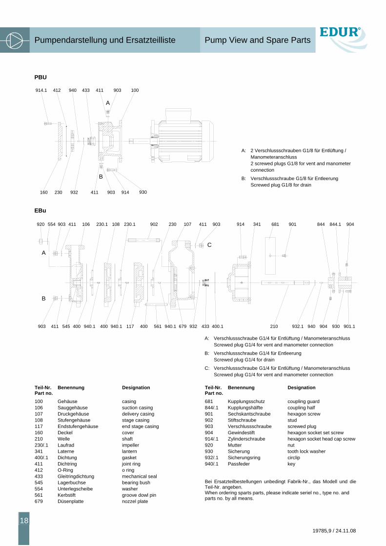
PBU
A: 2 Verschlussschrauben G1/8 für Entlüftung / Manometeranschluss 2 screwed plugs G1/8 for vent and manometer connection
B: Verschlussschraube G1/8 für Entleerung Screwed plug G1/8 for drain
EBu
A: Verschlussschraube G1/4 für Entlüftung / Manometeranschluss Screwed plug G1/4 for vent and manometer connection
B: Verschlussschraube G1/4 für Entleerung Screwed plug G1/4 for drain
C: Verschlussschraube G1/4 für Entlüftung / Manometeranschluss Screwed plug G1/4 for vent and manometer connection
Teil-Nr. Part no.
Benennung Designation Teil-Nr. Part no.
Benennung Designation
100 Gehäuse casing 681 Kupplungsschutz coupling guard 106 Sauggehäuse suction casing 844/.1 Kupplungshälfte coupling half 107 Druckgehäuse delivery casing 901 Sechskantschraube hexagon screw 108 Stufengehäuse stage casing 902 Stiftschraube stud 117 Endstufengehäuse end stage casing 903 Verschlussschraube screwed plug 160 Deckel cover 904 Gewindestift hexagon socket set screw 210 Welle shaft 914/.1 Zylinderschraube hexagon socket head cap screw230/.1 Laufrad impeller 920 Mutter nut 341 Laterne lantern 930 Sicherung tooth lock washer 400/.1 Dichtung gasket 932/.1 Sicherungsring circlip 411 Dichtring joint ring 940/.1 Passfeder key 412 O-Ring o ring 433 Gleitringdichtung mechanical seal 545 Lagerbuchse bearing bush 554 Unterlegscheibe washer 561 Kerbstift groove dowl pin 679 Düsenplatte nozzel plate
Bei Ersatzteilbestellungen unbedingt Fabrik-Nr., das Modell und die Teil-Nr. angeben. When ordering sparts parts, please indicate seriel no., type no. and parts no. by all means.
914.1 412 940 433 903411 100
160 230 932 903411 914 930
A
B
561940.1903 411 400545 400 940.1 117 400
B
A
400.1679940.1 433932 210
C
902903920 554 411 106 230.1 108 230.1 903107230 411 914 341 681
940932.1 904 930 901.1
901 844 844.1 904
Pumpendarstellung und Ersatzteilliste Pump View and Spare Parts
19785,9 / 24.11.08
19
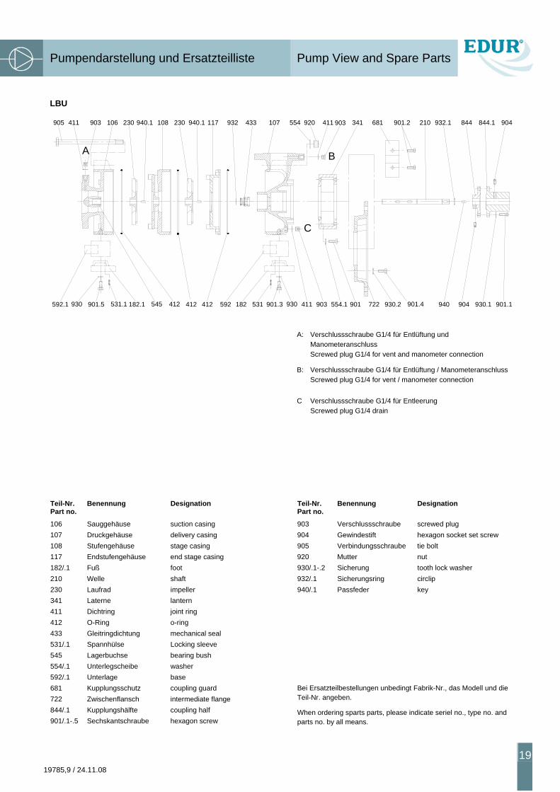
LBU
A: Verschlussschraube G1/4 für Entlüftung und Manometeranschluss Screwed plug G1/4 for vent and manometer connection
B: Verschlussschraube G1/4 für Entlüftung / Manometeranschluss Screwed plug G1/4 for vent / manometer connection
C Verschlussschraube G1/4 für Entleerung Screwed plug G1/4 drain
Teil-Nr. Part no.
Benennung Designation Teil-Nr. Part no.
Benennung Designation
106 Sauggehäuse suction casing 903 Verschlussschraube screwed plug 107 Druckgehäuse delivery casing 904 Gewindestift hexagon socket set screw 108 Stufengehäuse stage casing 905 Verbindungsschraube tie bolt 117 Endstufengehäuse end stage casing 920 Mutter nut 182/.1 Fuß foot 930/.1-.2 Sicherung tooth lock washer 210 Welle shaft 932/.1 Sicherungsring circlip 230 Laufrad impeller 940/.1 Passfeder key 341 Laterne lantern 411 Dichtring joint ring 412 O-Ring o-ring 433 Gleitringdichtung mechanical seal 531/.1 Spannhülse Locking sleeve 545 Lagerbuchse bearing bush 554/.1 Unterlegscheibe washer 592/.1 Unterlage base 681 Kupplungsschutz coupling guard 722 Zwischenflansch intermediate flange 844/.1 Kupplungshälfte coupling half 901/.1-.5 Sechskantschraube hexagon screw
Bei Ersatzteilbestellungen unbedingt Fabrik-Nr., das Modell und die Teil-Nr. angeben.
When ordering sparts parts, please indicate seriel no., type no. and parts no. by all means.
A B
C
905 411 903 106 230 940.1 230 940.1 932 433 107 554 920 411 903 341 681 901.2 844.1 904
592.1 182.1901.5930 531.1 412 412 592 182 531 901.3 930 411 903 722554.1 901 930.2 901.4
210 932.1 844
904940 930.1 901.1
117108
412545
Ergänzende Hinweise Additional Instructions
20 19785,9 / 24.11.08
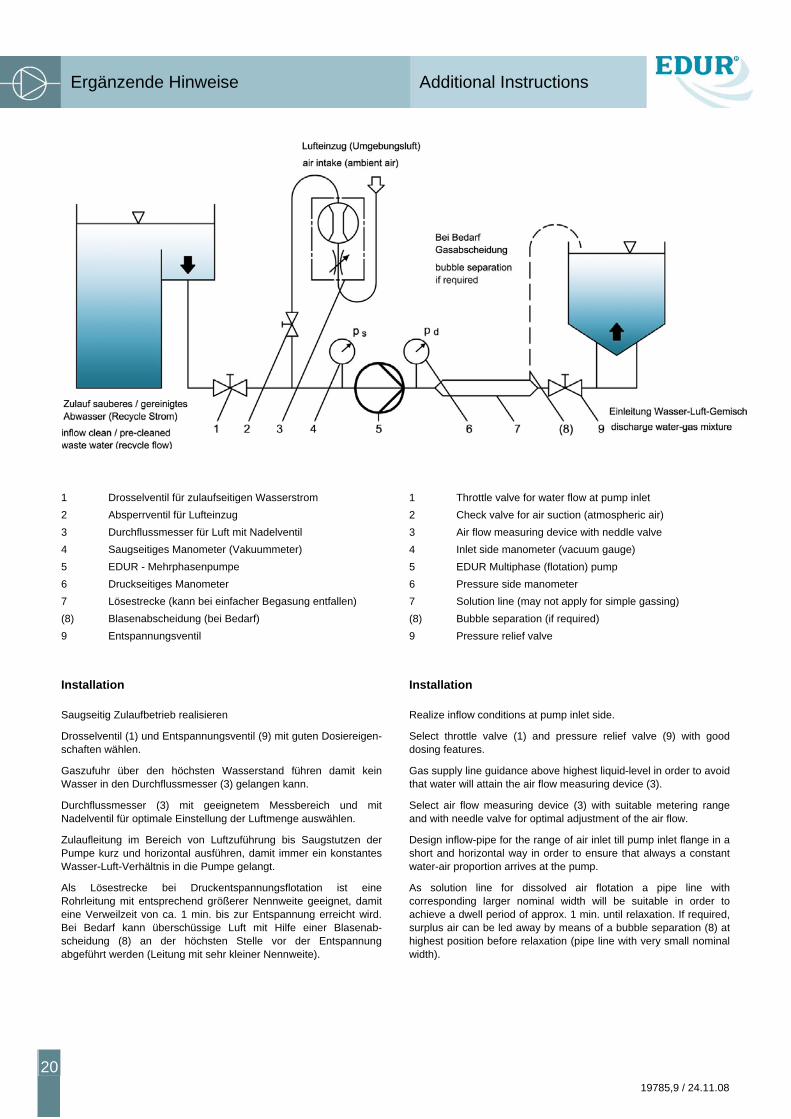
1 Drosselventil für zulaufseitigen Wasserstrom 2 Absperrventil für Lufteinzug 3 Durchflussmesser für Luft mit Nadelventil 4 Saugseitiges Manometer (Vakuummeter) 5 EDUR - Mehrphasenpumpe 6 Druckseitiges Manometer 7 Lösestrecke (kann bei einfacher Begasung entfallen) (8) Blasenabscheidung (bei Bedarf) 9 Entspannungsventil
Installation
Saugseitig Zulaufbetrieb realisieren
Drosselventil (1) und Entspannungsventil (9) mit guten Dosiereigen-schaften wählen.
Gaszufuhr über den höchsten Wasserstand führen damit kein Wasser in den Durchflussmesser (3) gelangen kann.
Durchflussmesser (3) mit geeignetem Messbereich und mit Nadelventil für optimale Einstellung der Luftmenge auswählen.
Zulaufleitung im Bereich von Luftzuführung bis Saugstutzen der Pumpe kurz und horizontal ausführen, damit immer ein konstantes Wasser-Luft-Verhältnis in die Pumpe gelangt.
Als Lösestrecke bei Druckentspannungsflotation ist eine Rohrleitung mit entsprechend größerer Nennweite geeignet, damit eine Verweilzeit von ca. 1 min. bis zur Entspannung erreicht wird. Bei Bedarf kann überschüssige Luft mit Hilfe einer Blasenab-scheidung (8) an der höchsten Stelle vor der Entspannung abgeführt werden (Leitung mit sehr kleiner Nennweite).
1 Throttle valve for water flow at pump inlet 2 Check valve for air suction (atmospheric air) 3 Air flow measuring device with neddle valve 4 Inlet side manometer (vacuum gauge) 5 EDUR Multiphase (flotation) pump 6 Pressure side manometer 7 Solution line (may not apply for simple gassing) (8) Bubble separation (if required) 9 Pressure relief valve
Installation
Realize inflow conditions at pump inlet side.
Select throttle valve (1) and pressure relief valve (9) with good dosing features.
Gas supply line guidance above highest liquid-level in order to avoid that water will attain the air flow measuring device (3).
Select air flow measuring device (3) with suitable metering range and with needle valve for optimal adjustment of the air flow.
Design inflow-pipe for the range of air inlet till pump inlet flange in a short and horizontal way in order to ensure that always a constant water-air proportion arrives at the pump.
As solution line for dissolved air flotation a pipe line with corresponding larger nominal width will be suitable in order to achieve a dwell period of approx. 1 min. until relaxation. If required, surplus air can be led away by means of a bubble separation (8) at highest position before relaxation (pipe line with very small nominal width).
Ergänzende Hinweise Additional Instructions
19785,9 / 24.11.08
21
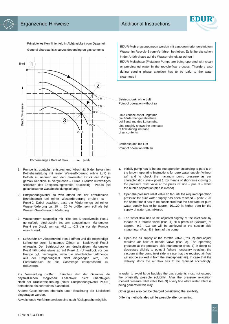
1. Pumpe ist zunächst entsprechend Abschnitt 5 der bekannten Betriebsanleitung mit reiner Wasserförderung (ohne Luft) in Betrieb zu nehmen und den maximalen Druck der Pumpe gemäß Kennlinie zu vergleichen – Punkt 1 (durch kurzzeitiges schließen des Entspannungsventils, druckseitig - Pos.9) (bei geschlossener Gasabscheidungsleitung).
2. Entspannungsventil so weit öffnen bis der erforderliche Betriebsdruck bei reiner Wasserförderung erreicht ist – Punkt 2. Dabei beachten, dass die Fördermenge bei reiner Wasserförderung ca. 10 ... 20 % größer sein soll als bei Wasser-Gas-Gemisch-Förderung.
3. Wasserstrom saugseitig mit Hilfe des Drosselventils Pos.1 geringfügig eindrosseln bis am saugseitigem Manometer Pos.4 ein Druck von ca. -0,2 ... -0,3 bar vor der Pumpe erreicht wird.
4. Luftzufuhr am Absperrventil Pos.2 öffnen und die notwendige Luftmenge durch langsames Öffnen am Nadelventil Pos.3 einregeln. Der Betriebsdruck am druckseitigen Manometer Pos.6 fällt dabei etwas ab auf Punkt 3. (Unterdruck vor der Pumpe ggf. nachregeln, wenn die erforderliche Luftmenge aus der Umgebungsluft nicht eingesogen wird). Bei Förderabbruch ist die Gasmenge entsprechend zu reduzieren.
Zur Vermeidung großer Bläschen darf der Gasanteil die physikalischen möglichen Löslichkeit nicht übersteigen. Nach der Druckentspannung (hinter Entspannungsventil Pos.9 ) entsteht so ein sehr feines Blasenbild. Andere Gase können ebenfalls unter Beachtung der Löslichkeit eingetragen werden. Abweichende Verfahrensweisen sind nach Rücksprache möglich.
1. Initially pump has to be put into operation according to para 5 of the known operating instructions for pure water supply (without air) and to check the maximum pump pressure as per characteristic curve – point 1 (by means of short-time closing of the pressure relief valve at the pressure side – pos. 9 – while the bubble separation pipe is closed)
2. Open the pressure relief valve so far until the required operation pressure for pure water supply has been reached – point 2. At the same time it has to be considered that the flow rate for pure water supply has to be approx. 10…20 % higher than for the supply of water-gas mixtures
3. The water flow has to be adjusted slightly at the inlet side by means of a throttle valve (Pos. 1) till a pressure (vacuum) of approx. -0,2…-0,3 bar will be achieved at the suction side manometer (Pos. 4) in front of the pump
4. Open the air supply at the throttle valve (Pos. 2) and adjust required air flow at needle valve (Pos. 3). The operating pressure at the pressure side manometer (Pos. 6) in doing so decreases slightly to point 3 (where necessary re-adjust the vacuum at the pump inlet side in case that the required air flow will not be sucked in from the atmospheric air). In case that the delivery stops the air flow has to be reduced accordingly.
In order to avoid large bubbles the gas contents must not exceed the physically possible solubility. After the pressure relaxation (behind pressure relief valve Pos. 9) a very fine white water effect is being generated this way.
Other gases also can be charged considering the solubility.
Differing methods also will be possible after consulting.
EDUR-Mehrphasenpumpen werden mit sauberem oder gereinigtem Wasser im Recycle-Strom-Verfahren betrieben. Es ist bereits schon in der Anfahrphase auf die Wasserreinheit zu achten ! EDUR Multiphase (Flotation) Pumps are being operated with clean or pre-cleaned water in the recycle-flow process. Therefore also during starting phase attention has to be paid to the water cleanness !
[bar]
[m³/h] Fördermenge / Rate of Flow
Dru
ck /
Pre
ssur
e
Prinzipielles Kennlinienfeld in Abhängigkeit vom Gasanteil
Betriebspunkt ohne Luft
Linie kennzeichnet ungefährdie Fördermengenabnahmebei Zunahme des Luftanteils.
Betriebspunkt mit Luft
Point of operation without air
General characteristic curves depending on gas contents
of air contents.of flow during increaseLine roughly shows the decrease
Point of operation with air
10 %
15 %
20 %
0 %
5 %
1
2
3
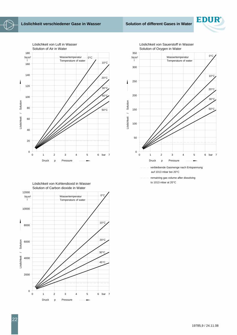
Löslichkeit verschiedener Gase in Wasser Solution of different Gases in Water
22 19785,9 / 24.11.08
0 1 2 3 4 5 6 7bar0
20
40
60
80
100
120
140
160
180
0°C
10°C
20°C
50°C
40°C
30°C
verbleibende Gasmenge nach Entspannung
remaining gas volume after dissolving
Ncm³l
WassertemperaturTemperature of water
Druck p Pressure
Lösl
ichk
eit
/
Sol
utio
n
Lösl
ichk
eit
/
Sol
utio
n
00
350Ncm³
l
1 2 3 4 5 bar6 7
Druck p Pressure
Temperature of waterWassertemperatur
50°C
20°C
30°C
0°C
10°C
300
250
200
150
100
50
00
Lösl
ichk
eit
/
Sol
utio
n
Ncm³l
12000
Temperature of waterWassertemperatur
2
Druck p Pressure
1 3
30°C
4 5 bar6 7
45°C
0°C
10°C
20°C
10000
8000
6000
4000
2000
auf 1013 mbar bei 20°C
to 1013 mbar at 20°C
Löslichkeit von Luft in WasserSolution of Air in Water
Löslichkeit von Sauerstoff in WasserSolution of Oxygen in Water
Löslichkeit von Kohlendioxid in WasserSolution of Carbon dioxide in Water