Embed Size (px)
Citation preview

source-to-emitter.com
Meibes Cool Interface Unit (CIU)
LogoCool
Nominal output 3-6-12-20 kW
LogoCool M-Line - Product codeM-Line 9 - 24kW: 10610.1
Data Sheet
LogoCool S-Line - Product codeS-Line 1 - 5kW: 10610.32S-Line 2 - 12kW: 10610.22S-Line 5 - 16kW: 10610.12
Features
• Small dimensions
• Sealed case - including all external connections - to avoid condensation
• 30mm internal insulation
• Successfully tested at room temperatures >30°C and up to 90% humidity
• Supplied with silica gel pads to collect any condensation that occurs after commissioning or inspection
• Selectable duty offering a range of different outputs, easy to setup
• Case with lift-off latches making it easy to open in confined spaces
• Top entry connections
• Stainless steel expansion vessel (secondary circuit)
• Ultrasonic heat meter (cooling mode) with M-Bus connectivity
• A-rated circulation pump (secondary circuit)
2 LogoCool 3-6-12-20 kW We reserve the right to change designs and technical specifications of our products.

Meibes LogoCool S-Line
Cooling Interface Unit (CIU)
Nominal outputs: 3kW, 6kW and 12kW
Meibes LogoCool M-Line
Cooling Interface Unit (CIU)
Nominal output: 20kW
Meibes Cooling Interface Unit (CIU) LogoCool 3-6-12-20 kW
3LogoCool 3-6-12-20 kW We reserve the right to change designs and technical specifications of our products.
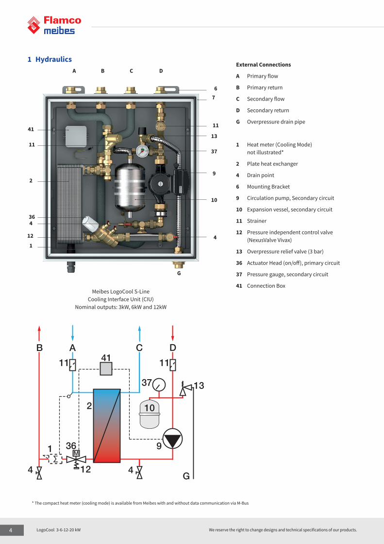
1 Hydraulics External Connections
A Primary flow
B Primary return
C Secondary flow
D Secondary return
G Overpressure drain pipe
1 Heat meter (Cooling Mode) not illustrated*
2 Plate heat exchanger
4 Drain point
6 Mounting Bracket
9 Circulation pump, Secondary circuit
10 Expansion vessel, secondary circuit
11 Strainer
12 Pressure independent control valve (NexusValve Vivax)
13 Overpressure relief valve (3 bar)
36 Actuator Head (on/off), primary circuit
37 Pressure gauge, secondary circuit
41 Connection Box
A B C D
G
67
11
13
37
9
10
4
41
11
2
364
12
1
∑M
AB C D
2
11 11
37 13
4 4
36
12
10
9
G
1
41
* The compact heat meter (cooling mode) is available from Meibes with and without data communication via M-Bus
Meibes LogoCool S-LineCooling Interface Unit (CIU)
Nominal outputs: 3kW, 6kW and 12kW
4 LogoCool 3-6-12-20 kW We reserve the right to change designs and technical specifications of our products.

External Connections
A Primary flow
B Primary return
C Secondary flow
D Secondary return
G Overpressure drain pipe
1 Heat meter (Cooling Mode) not illustrated*
2 Plate heat exchanger
4 Drain point
6 Mounting Bracket
9 Circulation pump, Secondary circuit
10 Expansion vessel, Secondary circuit
11 Strainer
12 Pressure independent control valve (NexusValve Vivax)
13 Overpressure relief valve (3 bar)
36 Actuator Head (on/off), primary circuit
37 Pressure gauge, secondary circuit
41 Connection Box
A B
CD
G
11
6
6
13
37
9
10
4
41
11
2
36
4
6
6
121
∑M
A B
C D
2
11
11
37 13
44
36
12
10
9
G
1
41
* The compact heat meter (cooling mode) is available from Meibes with and without data communication via M-Bus
Meibes LogoCool M-LineCooling Interface Unit (CIU)
Nominal output: 20kW
Meibes Cooling Interface Unit (CIU) LogoCool 3-6-12-20 kW
5LogoCool 3-6-12-20 kW We reserve the right to change designs and technical specifications of our products.

2 Specifications
2.1 Facts and Figures
Description Type Cooling Interface Unit for indirect comfort cooling
Mounting Wall mounted
Dimensions [mm],
Width x Depth x Height
(not incl. ball valves)
629 x 263 x 675
(nominal 3, 6 and 12 kW)
649 x 337 x 830
(nominal 20 kW)
Cooling System 2 pipe flow
Construction Pipework Insulated flexible stainless steel with brass fittings
Heat exchanger Stainless steel plate heat exchanger
Casing White powder coated sheet steel, fully insulated, PUR 0.025 W/mK
Primary Fluid Low pressure cold water
Secondary Fluid - Heating Low pressure cold water
Primary Duty (P1), nominal [kW] 3 6 12 20
Output range (P1, selectable) 1 … 5 kW 2 … 12 kW 5 … 16 kW 9 … 24 kW
Flow temperature (t11) 5 … 9ºC (refer to graphs, chapter 3)
Return temperature (t12) Dependent on flow temperature (refer to graphs in chapter 3)
Flow rate range (q1) [l/h] 100 … 450 450 … 1150 850 … 2050 1700 … 3300
Pressure rating PN16 PN10 (PN16 on request)
Secondary Duty (P2)
Flow temperature (t22) 8 … 10ºC
Return temperature (t21) 12 … 16 ºC
Flow rate range (q2) [l/h] 100 ... 800 250 ... 1730 700 ... 2300 1500 … 3400
Max. pressure 3 bar (restricted by over pressure relief valve)
Connections
All external connections 1“ BSP (male), top connections 2” BSP, topand bottomconnections
Electrical connections 230V, AC, 50Hz Primary
Primary and secondary fittings
Pressure independent control valve (PICV) NexusValve Vivax (min. p = 30 kPa) with thermo-electrical actuator (on/off)
Fittings and Drain points Primary and secondary circuit
Strainer Primary flow and secondary return
Circulation Pump Grundfos, A-rated, secondary circuit
Expansion vessel 2 litre, secondary circuit
Over pressure relief valve with pressure gauge 3 bar, secondary circuit
Optional
Ball valves 1” BSP 1 1/4” BSP
Heat Meter (cooling mode) Rossweiner “HeatSonic“, M-Bus (wired)
Δp2Δp1
t12
t11 t22
t21
q1 q2
DC
∆pqtP
= District Cooling
= Differential Pressure (kPa)= Flow Rate (l/s)= Temperature (ºC)= Power (kW)
SecondaryPrimary (DC)
P2P1
Δp2Δp1
t12
t11 t22
t21
q1 q2
DC
∆pqtP
= District Cooling
= Differential Pressure (kPa)= Flow Rate (l/s)= Temperature (ºC)= Power (kW)
SecondaryPrimary (DC)
P2P1
6 LogoCool 3-6-12-20 kW We reserve the right to change designs and technical specifications of our products.

PICV
sett
ing
[%]
Prim
ary
Flow
Rat
e [l/
h]Pr
imar
y Re
turn
Tem
pera
ture
[ºC]
Secondary Flow Rate [l/h]
Secondary Flow Rate [l/h]
Output [kW]
450
425
400
375
350
325
300
275
250
225
200
175
150
125
100
14.0
13.5
13.0
12.5
12.0
11.5
83
66
54
47
42
37
33
28
24
20
17
14
12
10
6
0.9 1.1 1.2 1.4 1.6 1.8 1.9 2.1 2.3 2.5 2.6 2.8 3.0 3.2 3.3 3.5 3.7 3.8 4.0 4.2 4.4
100 125 150 175 200 225 250 275 300 325 350 375 400 425 450 475 500 525 550 575 600
100 125 150 175 200 225 250 275 300 325 350 375 400 425 450 475 500 525 550 575 600
3 Graphs
3.1 LogoCool S-Line Nominal 3kW - Output, Flow Rate and Valve Setting3.1.1 Secondary Side at 8ºC/14ºC (ΔT=6K) Note The PICV settings in the graphs below are based on test results carried out on the cooling unit and can differ from those in the valve’s literature. The settings are approximate and will need fine tuning during commissioning using a flow meter (refer to installation manual).
Primary Flow Temperatures: 7ºC 6ºC 5ºC
Meibes Cooling Interface Unit (CIU) LogoCool 3-6-12-20 kW
7LogoCool 3-6-12-20 kW We reserve the right to change designs and technical specifications of our products.

3 Graphs
3.1.2 Secondary Side at 10°C/14°C (ΔT=4K)
PICV
sett
ing
[%]
Prim
ary
Flow
Rat
e [l/
h]Pr
imar
y Re
turn
Tem
pera
ture
[ºC]
Secondary Flow Rate [l/h]
Secondary Flow Rate [l/h]
Output [kW]
450
425
400
375
350
325
300
275
250
225
200
175
150
125
100
14.0
13.5
13.0
12.5
83
66
54
47
42
37
33
28
24
20
17
14
12
10
6
0.4 0.7 0.9 1.2 1.4 1.7 1.9 2.2 2.4 2.7 2.9 3.2 3.4 3.7 3.9
100 150 200 250 300 350 400 450 500 550 600 650 700 750 800
100 150 200 250 300 350 400 450 500 550 600 650 700 750 800
Primary Flow Temperatures: 9ºC 8ºC 7ºC 6ºC 5ºC
8 LogoCool 3-6-12-20 kW We reserve the right to change designs and technical specifications of our products.

3 Graphs
3.1.3 Secondary Side at 10ºC / 16ºC (ΔT = 6K)
PICV
sett
ing
[%]
Prim
ary
Flow
Rat
e [l/
h]Pr
imar
y Re
turn
Tem
pera
ture
[ºC]
Secondary Flow Rate [l/h]
Secondary Flow Rate [l/h]
Output [kW]
450
425
400
375
350
325
300
275
250
225
200
175
150
125
100
16.0
15.5
15.0
14.5
14.0
13.5
83
66
54
47
42
37
33
28
24
20
17
14
12
10
6
0.9 1.2 1.6 1.9 2.3 2.6 2.9 3.3 3.6 4.0 4.3 4.6 5.0 5.3 5.7
100 150 200 250 300 350 400 450 500 550 600 650 700 750 800
100 150 200 250 300 350 400 450 500 550 600 650 700 750 800
Primary Flow Temperatures: 9ºC 8ºC 7ºC 6ºC 5ºC
Meibes Cooling Interface Unit (CIU) LogoCool 3-6-12-20 kW
9LogoCool 3-6-12-20 kW We reserve the right to change designs and technical specifications of our products.

PICV
sett
ing
[%]
Prim
ary
Flow
Rat
e [l/
h]Pr
imar
y Re
turn
Tem
pera
ture
[ºC]
Secondary Flow Rate [l/h]
Secondary Flow Rate [l/h]
Output [kW]
1250
1200
1150
1100
1050
1000
950
900
850
800
750
700
650
600
550
500
450
400
350
300
13.5
13.0
12.5
12.0
11.5
11.0
100
90
80
72
66
58
53
48
44
39
35
32
28
25
22
18
15
11
7
3
1.7 2.1 2.4 2.8 3.1 3.5 3.8 4.2 4.5 4.9 5.2 5.6 5.9 6.3 6.6 7.0 7.3 7.7 8.0 8.4 8.7 9.1 9.4 9.8 10.1 10.5 10.8
250 300 350 400 450 500 550 600 650 700 750 800 850 900 950 100 1050 1100 1150 1200 1250 1300 1350 1400 1450 1500 1550
250 300 350 400 450 500 550 600 650 700 750 800 850 900 950 100 1050 1100 1150 1200 1250 1300 1350 1400 1450 1500 1550
area with lower accuracy (refer to PICV specifications)
3 Graphs
3.2 LogoCool S-Line Nominal 6kW - Output, Flow Rate and Valve Setting3.2.1 Secondary Side at 8ºC/14ºC (ΔT=6K) Note The PICV setting in the graphs are based on test results carried out on the cooling unit and can differ from those in the valve‘s literature. The settings are approximates and will need fine tuning during commissioning using a flow meter (refer to installation manual).
Primary Flow Temperatures: 7ºC 6ºC 5ºC
10 LogoCool 3-6-12-20 kW We reserve the right to change designs and technical specifications of our products.

3 Graphs
3.2.2 Secondary Side at 10°C/14°C (ΔT=4K)
PICV
sett
ing
[%]
Prim
ary
Flow
Rat
e [l/
h]Pr
imar
y Re
turn
Tem
pera
ture
[ºC]
Secondary Flow Rate [l/h]
Secondary Flow Rate [l/h]
Output [kW]
1250
1200
1150
1100
1050
1000
950
900
850
800
750
700
650
600
550
500
450
400
350
300
16.0
15.5
15.0
14.5
14.0
13.5
100
90
80
72
66
58
53
48
44
39
35
32
28
25
22
18
15
11
7
3
0.9 1.2 1.6 1.9 2.3 2.6 2.9 3.3 3.6 4.0 4.3 4.6 5.0 5.3 5.7
250 350 450 550 650 750 850 950 1050 1150 1250 1350 1450 1550 1650 1750 1850 1950
100 150 200 250 300 350 400 450 500 550 600 650 700 750 800
Primary Flow Temperatures: 9ºC 8ºC 7ºC 6ºC 5ºC
Resi
dual
Pum
p H
ead
< 3m
area with lower accuracy (refer to PICV specifications)
Resi
dual
Pum
p H
ead
< 3m
Meibes Cooling Interface Unit (CIU) LogoCool 3-6-12-20 kW
11LogoCool 3-6-12-20 kW We reserve the right to change designs and technical specifications of our products.

3 Graphs
3.2.2 Secondary Side at 10°C/16°C (ΔT=6K)
PICV
sett
ing
[%]
Prim
ary
Flow
Rat
e [l/
h]Pr
imar
y Re
turn
Tem
pera
ture
[ºC]
Secondary Flow Rate [l/h]
Secondary Flow Rate [l/h]
Output [kW]
1250
1200
1150
1100
1050
1000
950
900
850
800
750
700
650
600
550
500
450
400
350
300
16.0
15.5
15.0
14.5
14.0
13.5
100
90
80
72
66
58
53
48
44
39
35
32
28
25
22
18
15
11
7
3
1.7 2.4 3.1 3.8 4.5 5.2 5.9 6.6 7.3 8.0 8.7 9.4 10.1 10.8 11.5 12.2 12.9 13.6
250 350 450 550 650 750 850 950 1050 1150 1250 1350 1450 1550 1650 1750 1850 1950
250 350 450 550 650 750 850 950 1050 1150 1250 1350 1450 1550 1650 1750 1850 1950
Primary Flow Temperatures: 9ºC 8ºC 7ºC 6ºC 5ºC
Resi
dual
Pum
p H
ead
< 3m
area with lower accuracy (refer to PICV specifications)
Resi
dual
Pum
p H
ead
< 3m
12 LogoCool 3-6-12-20 kW We reserve the right to change designs and technical specifications of our products.
3 Graphs
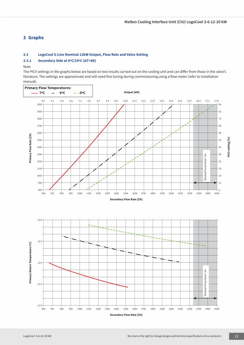
3.3 LogoCool S-Line Nominal 12kW Output, Flow Rate and Valve Setting3.3.1 Secondary Side at 8ºC/14ºC (ΔT=6K)Note The PICV settings in the graphs below are based on test results carried out on the cooling unit and can differ from those in the valve’s literature. The settings are approximate and will need fine tuning during commissioning using a flow meter (refer to installation manual).
Primary Flow Temperatures: 7ºC 6ºC 5ºC
PICV
sett
ing
[%]
Prim
ary
Flow
Rat
e [l/
h]
Secondary Flow Rate [l/h]
Output [kW]
2050
1950
1850
1750
1650
1550
1450
1350
1250
1150
1050
950
850
13.0
12.5
12.0
11.5
11.0
94
82
73
66
58
52
45
38
32
25
19
11
2
4.5 5.2 5.9 6.6 7.3 8.0 8.7 9.4 10.1 10.8 11.5 12.2 12.9 13.6 14.3 15.0 15.7 16.4 17.1 17.8
650 750 850 950 1050 1150 1250 1350 1450 1550 1650 1750 1850 1950 2050 2150 2250 2350 2450 2550
650 750 850 950 1050 1150 1250 1350 1450 1550 1650 1750 1850 1950 2050 2150 2250 2350 2450 2550
Resi
dual
Pum
p H
ead
< 3m
Resi
dual
Pum
p H
ead
< 3m
Secondary Flow Rate [l/h]
Prim
ary
Retu
rn T
empe
ratu
re [º
C]
Meibes Cooling Interface Unit (CIU) LogoCool 3-6-12-20 kW
13LogoCool 3-6-12-20 kW We reserve the right to change designs and technical specifications of our products.

Primary Flow Temperatures: 9ºC 8ºC 7ºC 6ºC 5ºC
3 Graphs
3.3.2 Secondary Side at 10ºC/14ºC (ΔT=4K)
PICV
sett
ing
[%]
Secondary Flow Rate [l/h]
Secondary Flow Rate [l/h]
Output [kW]
2050
1950
1850
1750
1650
1550
1450
1350
1250
1150
1050
950
850
14.0
13.5
13.0
12.5
94
82
73
66
58
52
45
38
32
25
19
11
2
3.0 3.5 3.9 4.4 4.9 5.3 5.8 6.3 6.7 7.2 7.7 8.1 8.6 9.1 5.2 10.0 10.5 10.9 11.4 11.8
650 750 850 950 1050 1150 1250 1350 1450 1550 1650 1750 1850 1950 2050 2150 2250 2350 2450 2550
650 750 850 950 1050 1150 1250 1350 1450 1550 1650 1750 1850 1950 2050 2150 2250 2350 2450 2550
Prim
ary
Flow
Rat
e [l/
h]Pr
imar
y Re
turn
Tem
pera
ture
[ºC]
Resi
dual
Pum
p H
ead
< 3m
Resi
dual
Pum
p H
ead
< 3m
14 LogoCool 3-6-12-20 kW We reserve the right to change designs and technical specifications of our products.

Secondary Flow Rate [l/h]
Prim
ary
Retu
rn T
empe
ratu
re [º
C]
Primary Flow Temperatures: 9ºC 8ºC 7ºC 6ºC 5ºC
3 Graphs
3.3.3 Secondary Side at 10ºC/16ºC (ΔT=6K)
PICV
sett
ing
[%]
Prim
ary
Flow
Rat
e [l/
h]
Secondary Flow Rate [l/h]
Output [kW]
2050
1950
1850
1750
1650
1550
1450
1350
1250
1150
1050
950
850
15.5
15.0
14.5
14.0
13.5
13.0
94
82
73
66
58
52
45
38
32
25
19
11
2
4.5 5.2 5.9 6.6 7.3 8.0 8.7 9.4 10.1 10.8 11.5 12.2 12.9 13.6 14.3 15.0 15.7 16.4 17.1 17.8
650 750 850 950 1050 1150 1250 1350 1450 1550 1650 1750 1850 1950 2050 2150 2250 2350 2450 2550
650 750 850 950 1050 1150 1250 1350 1450 1550 1650 1750 1850 1950 2050 2150 2250 2350 2450 2550
Resi
dual
Pum
p H
ead
< 3m
Resi
dual
Pum
p H
ead
< 3m
Meibes Cooling Interface Unit (CIU) LogoCool 3-6-12-20 kW
15LogoCool 3-6-12-20 kW We reserve the right to change designs and technical specifications of our products.

3 Graphs
3.4 LogoCool M-Line Nominal 20kW - Output, Flow Rate and Valve Setting 3.4.1 Secondary Side at 8ºC/14ºC (ΔT=6K)
PICV
sett
ing
[%]
Secondary Flow Rate [l/h]
Secondary Flow Rate [l/h]
Output [kW]
3300
3200
3100
3000
2900
2800
2700
2600
2500
2400
2300
2200
2100
2000
1900
1800
13.0
12.8
12.5
12.3
12.0
11.8
11.5
11.3
11.0
94
88
82
77
70
66
60
52
48
41
36
30
22
16
10
4
9.8 11.2 12.6 14.0 15.3 16.7 18.1 19.5 20.9 22.3 23.7
1400 1600 1800 200 2200 2400 2600 2800 3000 3200 3400
1400 1600 1800 2000 2200 2400 2600 2800 3000 3200 3400
Prim
ary
Flow
Rat
e [l/
h]Pr
imar
y Re
turn
Tem
pera
ture
[ºC]
Primary Flow Temperatures: 7ºC 6ºC 5ºC
16 LogoCool 3-6-12-20 kW We reserve the right to change designs and technical specifications of our products.

3 Graphs
3.4.2 Secondary Side at 10ºC/14ºC (ΔT=4K)
PICV
sett
ing
[%]
Secondary Flow Rate [l/h]
Secondary Flow Rate [l/h]
Output [kW]
3300
3200
3100
3000
2900
2800
2700
2600
2500
2400
2300
2200
2100
2000
1900
1800
1700
14.0
13.5
13.0
12.5
94
88
82
77
70
66
60
52
48
41
36
30
22
16
10
4
0
9.3 10.2 11.2 12.1 13.0 13.9 14.9 15.8
2000 2200 2400 2600 2800 3000 3200 3400
2000 2200 2400 2600 2800 3000 3200 3400
Prim
ary
Flow
Rat
e [l/
h]Pr
imar
y Re
turn
Tem
pera
ture
[ºC]
Primary Flow Temperatures: 9ºC 8ºC 7ºC 6ºC
Meibes Cooling Interface Unit (CIU) LogoCool 3-6-12-20 kW
17LogoCool 3-6-12-20 kW We reserve the right to change designs and technical specifications of our products.
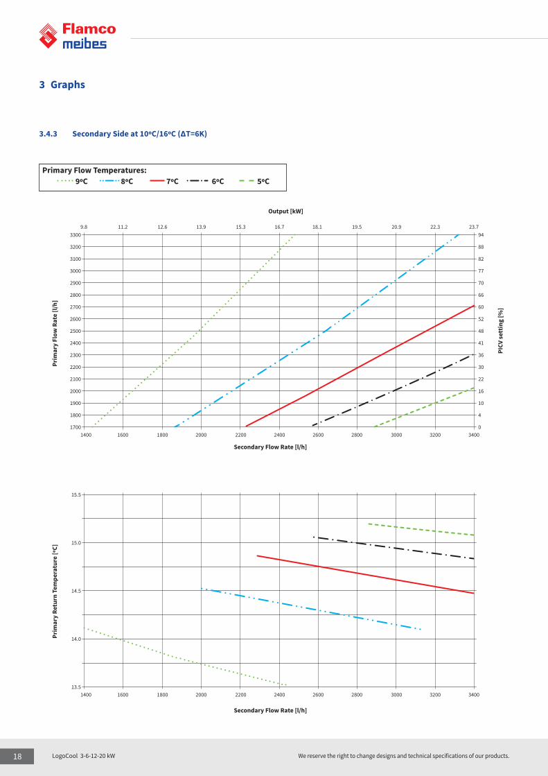
3 Graphs
3.4.3 Secondary Side at 10ºC/16ºC (ΔT=6K)
PICV
sett
ing
[%]
Prim
ary
Flow
Rat
e [l/
h]Pr
imar
y Re
turn
Tem
pera
ture
[ºC]
Secondary Flow Rate [l/h]
Secondary Flow Rate [l/h]
Output [kW]
3300
3200
3100
3000
2900
2800
2700
2600
2500
2400
2300
2200
2100
2000
1900
1800
1700
15.5
15.0
14.5
14.0
13.5
94
88
82
77
70
66
60
52
48
41
36
30
22
16
10
4
0
9.8 11.2 12.6 13.9 15.3 16.7 18.1 19.5 20.9 22.3 23.7
1400 1600 1800 2000 2200 2400 2600 2800 3000 3200 3400
1400 1600 1800 2000 2200 2400 2600 2800 3000 3200 3400
Primary Flow Temperatures: 9ºC 8ºC 7ºC 6ºC 5ºC
18 LogoCool 3-6-12-20 kW We reserve the right to change designs and technical specifications of our products.

3 Graphs
3.5 LogoCool S-Line Nominal 3,6 and 12 kW - Pressure Losses 3.5.1 Primary Side Pressure Loss and Primary System PressureNote An additional 0.3 bar needs to be added for the “NexusValve Vivax” to operate correctly (See graph below)
Flow Rate [l/h] Ballorex Dynamic Setting 100%
Ballorex Dynamic Setting 100%Flow Rate [l/h]
Flow Rate [l/s]
Flow Rate [l/s]
12 kW
12 kW
6 kW
6 kW
3 kW
3 kW
Pressure Loss Primary Side (Without Heat Meter)
Required Primary Pressure (Without Heat Meter)
1.20
1.10
1.00
0.90
0.80
0.70
0.60
0.50
0.40
0.30
0.20
0.10
0.00
1.20
1.10
1.00
0.90
0.80
0.70
0.60
0.50
0.40
0.30
0.000 0.056 0.111 0.167 0.222 0.278 0.333 0.389 0.444 0.500 0.556 0.611
0.000 0.056 0.111 0.167 0.222 0.278 0.333 0.389 0.444 0.500 0.556
0 200 400 600 800 1000 1200 1400 1600 1800 2000 2200
0 200 400 600 800 1000 1200 1400 1600 1800 2000
Pres
sure
Los
s [ba
r]Pr
imar
y Sy
stem
Pre
ssur
e [b
ar]
Meibes Cooling Interface Unit (CIU) LogoCool 3-6-12-20 kW
19LogoCool 3-6-12-20 kW We reserve the right to change designs and technical specifications of our products.

3 Graphs
3.5.2 Secondary Side Pressure Loss and Pump Performance
3.5.3 Residual Pump Head
Flow Rate [l/h]
Flow Rate [l/h]
Constant Speed
Proportional Pressure Mode
Flow Rate [l/s]
12 kW
III
III
II
II
I
I
3 kW; 6 kW
Pressure Loss Secondary Side
Residual Pump Head Grundfos UPMXL Auto 25-105 (180)
1.00
0.90
0.80
0.70
0.60
0.50
0.40
0.30
0.20
0.10
0.00
11
10
9
8
7
6
5
4
3
2
1
0
0.000 0.056 0.111 0.167 0.222 0.278 0.333 0.389 0.444 0.500 0.556 0.611 0.667 0.722
0 200 400 600 800 1000 1200 1400 1600 1800 2000 2200 2400 2600
0 200 400 600 800 1000 1200 1400 1600 1800 2000 2200 2400 2600
Pres
sure
Los
s [ba
r]Pu
mp
Hea
d [m
]
20 LogoCool 3-6-12-20 kW We reserve the right to change designs and technical specifications of our products.
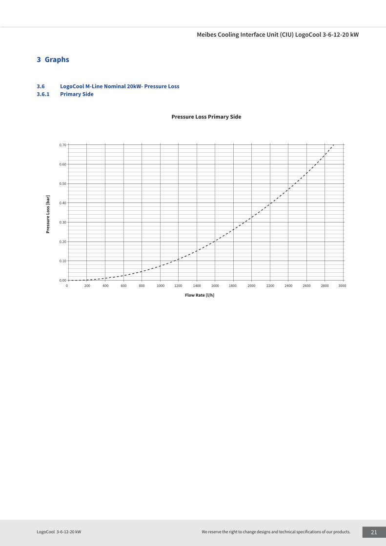
3 Graphs
3.6 LogoCool M-Line Nominal 20kW- Pressure Loss 3.6.1 Primary Side
Flow Rate [l/h]
Pressure Loss Primary Side
0.70
0.60
0.50
0.40
0.30
0.20
0.10
0.000 200 400 600 800 1000 1200 1400 1600 1800 2000 2200 2400 2600 2800 3000
Pres
sure
Los
s [ba
r]
Meibes Cooling Interface Unit (CIU) LogoCool 3-6-12-20 kW
21LogoCool 3-6-12-20 kW We reserve the right to change designs and technical specifications of our products.

3 Graphs
3.6.2 Secondary Side
Flow Rate [l/h]
Pressure Loss Secondary Side
0.30
0.25
0.20
0.15
0.10
0.05
0.000 200 400 600 800 1000 1200 1400 1600 1800 2000 2200 2400 2600 2800 3000
Pres
sure
Los
s [ba
r]
22 LogoCool 3-6-12-20 kW We reserve the right to change designs and technical specifications of our products.

3 Graphs
3.6.3 Residual Pump Head
Flow Rate [l/h]
Residual Pump Head
11
10
9
8
7
6
5
4
3
2
1
00 200 400 600 800 1000 1200 1400 1600 1800 2000 2200 2400 2600 2800 3000 3200 3400 3600 3800 4000 4200 4400 4600 4800 5000
Pum
p H
ead
[m]
III
III
II
II
I
I
Meibes Cooling Interface Unit (CIU) LogoCool 3-6-12-20 kW
23LogoCool 3-6-12-20 kW We reserve the right to change designs and technical specifications of our products.
www.flamcogroup.com
BRO
_Log
oCoo
l_Da
tash
eet_
ENG_
2021
-02
Germany
Austria
Switzerland
We deliver products for plumbing and heating installers in over 70 countries. Sales are handled by the branches and wholesalers who known the local market and can offer you professional advice at any time.
United KingdomFrance
United Arab Emirates
GermanySwitzerland
DenmarkSweden
HungaryPoland
Estonia
Finland
Russia
AustriaCzech Republic
Belgium and Luxembourg The Netherlands
Italy
ChinaUnited States