Embed Size (px)
Citation preview
Meilhaus Electronic Manual
ME-5004 1.2E
Plug-on Board for ME-5000 Series with opto-isolated Digital I/Os
(alternative configuration: Frequency Measurement and Pulse Generator)
ImprintME-5810 Manual
Version 1.2E Issued on: 17. Oktober 2013
Meilhaus Electronic GmbH Fischerstraße 2 D-82178 Puchheim/Munich Germany http://www.meilhaus.com
© Copyright 2013 Meilhaus Electronic GmbH
All rights reserved. No part of this publication may be reproduced or distributed in any form whether photocopied, printed, put on microfilm or be stored in any electronic media without the expressed written consent of Meilhaus Electronic GmbH.
Important note: The information contained in this manual has been reviewed with great care and is believed to be complete and accurate. Meilhaus Electronic assumes no responsibility for its use, any infringements of patents or other rights of third parties which may result from use of this manual or the product. Meilhaus Electronic assumes no responsibility for any problems or damage which may result from errors or omissions. Specifications and instructions are subject to change without notice.
Borland Delphi is a trademark of Borland International Inc. Turbo/Borland C is a trademark of Borland International Inc. Visual C++ and Visual Basic are trademarks of the Microsoft Corporation. VEE Pro and VEE OneLab are trademarks of Agilent Technologies. ME-VEC and ME-FoXX are trademarks of Meilhaus Electronic. Other company names and product names found in the text of this manual are also trademarks of the companies involved.
Manual ME-5004 Rev. 1.2E
Table of Contents1 Introduction...................................................................................................... 5
1.1 Important Notes ..................................................................................... 51.1.1 Intended Use ................................................................................ 51.1.2 Improper Use................................................................................ 61.1.3 Unforeseeable Misuse.................................................................... 6
1.2 Scope of Supply....................................................................................... 7
1.3 Features .................................................................................................. 8
1.4 System Requirements ............................................................................ 10
1.5 Software Support .................................................................................. 10
2 Initial Operation ............................................................................................. 11
2.1 Software Installation ............................................................................. 11
2.2 Test Program ........................................................................................ 11
2.3 Fitting the Plug-on Boards .................................................................... 12
3 Hardware ........................................................................................................ 15
3.1 Block Diagram ...................................................................................... 15
3.2 ME-5004 cPCI/PCIe .......................................................................... 16
3.3 Digital Input/Output ........................................................................... 173.3.1 Opto-isolated Inputs ........................................................... 173.3.2 Opto-isolated Outputs .......................................................... 18
3.3.2.1 Sink Driver ................................................................. 183.3.2.2 Source Driver.............................................................. 20
3.3.3 External Trigger ........................................................................ 213.4 Frequency Input/Output ................................................................ 21
3.5 External Interrupt .............................................................................. 22
4 Programming.................................................................................................. 23
4.1 Single Operation Mode......................................................................... 254.1.1 Digital Input/Output .......................................................... 254.1.2 Frequency Input/Output ....................................................... 26
4.1.2.1 Frequency Measurement ........................................ 274.1.2.2 Pulse Generator ....................................................... 28
4.2 Interrupt Operation ......................................................................... 294.2.1 Bit-pattern Change .................................................................. 294.2.2 Bit-pattern Compare .............................................................. 31
Meilhaus Electronic Seite 3 Table of Contents
Rev. 1.2E Manual ME-5004
Appendix ...............................................................................................................33
A Specifications ........................................................................................33
B Pinout ..................................................................................................39B1 37-pin D-Sub (ST1).....................................................................40
C Accessories ............................................................................................41
D Technical Questions..............................................................................42D1 Hotline.........................................................................................42D2 Service address..............................................................................42D3 Driver Update ..............................................................................42
E Index.....................................................................................................43
Table of Contents Seite 4 Meilhaus Electronic
Manual ME-5004 Rev. 1.2E
1 IntroductionValued customer,
Thank you for purchasing this device from Meilhaus Electronic. You ha-ve chosen an innovative high technology product that left our premises in a fully functional and new condition.
Take the time to carefully examine the contents of the package for any loss or damage that may have occurred during shipping. If there are any items missing or if an item is damaged, contact us immediately.
Before you install the board in your computer, we recommend to read this manual carefully, especially the chapter describing board installation.
1.1 Important Notes
1.1.1 Intended Use
The plug-on boards of the ME-5000 series require a base board of the ME-5000 series and will be plugged onto these and extend the functio-nality of the base boards. Depending on the PC platform the plug-on board needs an additional:
• … free PCI Express slot (PCIe) or
• … free CompactPCI slot (cPCI),
however without using the PCI slot connector.
Please follow the instructions of chapter 2.3 on page 12 of this document and the manual of your computer for the procedure when fitting additio-nal hardware componets.
Observe the following notes and specifications starting on page 33:
• Make sure that heat can be dissipated from the board well enough inside the PC housing.
• Unused inputs must always be connected to the reference ground of their subdevice, in order to avoid crosstalk between the input channels.
Meilhaus Electronic Seite 5 Introduction
Rev. 1.2E Manual ME-5004
• When using the configuration „pulse generator“ (FO) unused output pins should not be connected.When using the sink driver the outputs are in a high-impedance state, when using the source driver they are connected to ground.
• The opto-isolated inputs and outputs provide electrical isolation bet-ween device and application of up to 1000 V with respect to the PC ground.
• Note that the computer must be switched on first before any voltage is applied to the board through external circuitry.
• Connecting or disconnecting any of the the board's connectors must always be done when all the components are powered down.
• Make sure that when touching the board, or when plugging in the connecting cable, it is not possible for static discharges to pass through the board.
• Ensure that the connecting cable is securely seated. The plug must be fully inserted into the D-sub socket, and secured using both screws. Only in this way can the board be expected to function properly.
1.1.2 Improper Use
Plug-on boards must never be operated outside the PC. Never connect the devices to electrically live parts, and particularly not to any that carry mains voltage.
Make sure that the external circuitry connected to the device cannot come into contact with electrically live parts. Connecting or disconnec-ting any of the the connectors must always be done when powered down.
1.1.3 Unforeseeable Misuse
The device is not suitable for use as a child's toy, for domestic purposes or under adverse ambient conditions (such as in the open air). The user must take appropriate precautions to avoid unforeseeable misuse.
Introduction Seite 6 Meilhaus Electronic
Manual ME-5004 Rev. 1.2E
1.2 Scope of SupplyWe do, of course, endeavour to supply you a complete product package. Nevertheless, to make entirely sure that your supply is complete, you can check the contents of your package with the help of the following list.
Your package should contain the following parts:
• Opto-isolated digital-I/O board used as a plug-on board for the base boards of the ME-5000 series
• Manual in PDF format on CD/DVD
• Driver software on CD/DVD
• 37-pin D-sub mating connector
Meilhaus Electronic Seite 7 Introduction
Rev. 1.2E Manual ME-5004
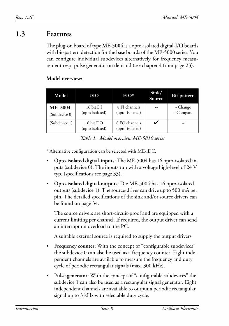
1.3 Features The plug-on board of type ME-5004 is a opto-isolated digital-I/O boards with bit-pattern detection for the base boards of the ME-5000 series. You can configure individual subdevices alternatively for frequency measu-rement resp. pulse generator on demand (see chapter 4 from page 23).
Model overview:
* Alternative configuration can be selected with ME-iDC.
• Opto-isolated digital-inputs: The ME-5004 has 16 opto-isolated in-puts (subdevice 0). The inputs run with a voltage high-level of 24 V typ. (specifications see page 33).
• Opto-isolated digital-outputs: Die ME-5004 has 16 opto-isolated outputs (subdevice 1). The source-driver can drive up to 500 mA per pin. The detailed specifications of the sink and/or source drivers can be found on page 34.
The source drivers are short-circuit-proof and are equipped with a current limiting per channel. If required, the output driver can send an interrupt on overload to the PC.
A suitable external source is required to supply the output drivers.
• Frequency counter: With the concept of “configurable subdevices” the subdevice 0 can also be used as a frequency counter. Eight inde-pendent channels are available to measure the frequency and duty cycle of periodic rectangular signals (max. 300 kHz).
• Pulse generator: With the concept of “configurable subdevices” the subdevice 1 can also be used as a rectangular signal generator. Eight independent channels are available to output a periodic rectangular signal up to 3 kHz with selectable duty cycle.
Model DIO FIO* Sink/Source Bit-pattern
ME-5004(Subdevice 0)
16 bit DI(opto-isolated)
8 FI channels(opto-isolated)
-- - Change- Compare
(Subdevice 1) 16 bit DO(opto-isolated)
8 FO channels(opto-isolated)
4 --
Table 1: Model overview ME-5810 series
Introduction Seite 8 Meilhaus Electronic
Manual ME-5004 Rev. 1.2E
• Sink/source selection: You can switch the output ports over from sink to source drivers or high impedance by software for an optimal adaption in industrial applications. “High impedance” means that the voltage level at the output pin depends on your external applica-tion.
• Bit-pattern detection: If required, the bit-pattern of an digital input port can be monitored. Depending on the mode an interrupt can be generated, if the bit-pattern changes or is equal/not equal to a given bit-pattern.
• The isolation voltage between the opto-isolated inputs/outputs and PC-ground is 1 kVACRMS.
• The opto-isolated digital inputs of the ME-5004 are equipped with an overvoltage protection diode that can discharge voltage pulses to ground for a short period of time.
For data transmission between PC memory and the base board the ME-5004 must share the bandwidth with the base board. The actual transmission rate depends on the operating mode and on the configura-tion of your PC.
Depending on requirements, you can select from the following operation modes:
• Single: In this operation mode, a single value can be read or written under software control (see chapter 4.1 on page 25).
• Interrupt: For interrupt handling in the modes "bit-pattern change" and "bit-pattern compare" (see chapter 4.2 on page 29).
Customer-specific versions of the firmware are available on request.
Meilhaus Electronic Seite 9 Introduction
Rev. 1.2E Manual ME-5004
1.4 System RequirementsThe plug-on board requires a base board of the ME-5000 series and occu-pies a free PCI Express or CompactPCI slot however without using the PCI slot connector. This saves the resources of your PC. The board is supported by the Meilhaus Intelligent Driver System (ME-iDS) from Windows 2000 upwards (Linux under development).
1.5 Software Support The plug-on boards of the ME-5000 series are supported by the Meilhaus Intelligent Driver System (ME-iDS). The ME-iDS is an unified driver system usable across devices and operating systems. It supports Windows 8/7/Vista/XP/2000 (Linux under development) and contains a universal function library (API) for programming.
You will find a detailed description of the functions in the ME-iDS ma-nual, a copy of which is on the CD/DVD supplied.
Please also observe the notes in the appropriate README files.
Introduction Seite 10 Meilhaus Electronic
Manual ME-5004 Rev. 1.2E
2 Initial OperationPlease read your computer manual instructions on how to install new hardware components before installing the board.
2.1 Software Installation
• Installation under Windows
The following basic procedure should be used:
If you have received the driver software as an archive file please un-pack the software before installing the board. First choose a directory on your computer (e. g. C:\Temp\Meilhaus\ME-iDS).
Use the Meilhaus Intelligent Driver System (ME-iDS) for programming your new data acquisition hardware. For installation and operation of the driver system please follow the documentation in electronic form inclu-ded with the software package.
• Installation under Linux
Note the installation instructions included with archive file of the appro-priate driver.
Linux under development!
2.2 Test Program• ME-PowerLab3: Run the program from the Windows Start menu.
This will allow you to test all the important functions of the hard-ware.
• You will find simple test programs in the SDK of the ME-iDS, in the "Test Executables32" or "Test Executables64" subfolders.
Meilhaus Electronic Seite 11 Initial Operation
Rev. 1.2E Manual ME-5004
2.3 Fitting the Plug-on BoardsThe boards should be handled with care in order to make sure that the device is not damaged by electrostatic discharge (ESD), mechanical stress or unsuitable current surges. Precautions should also be taken to avoid an electric shock. Ensure that standard ESD safty precautions are taken. At least one hand should be grounded in order to dissipate any static charge.
Observe the following procedure:
1. If the basic board is installed, you must first remove it in order to be able to insert the plug-on board. Here you should observe the procedure as described in the manual for your PC system.
2. Make sure that electrostatic discharges cannot take place through the plug-on board or the basic board as you plug it in. Follow the standard ESD safty precautions.
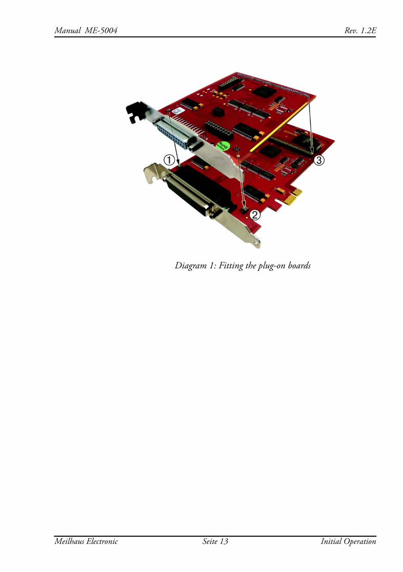
3. Push the plug-on board carefully, and with only a little force, on to the male connector provided for it (see diagram 1, items 1, 2 and 3). Check that the board is fully plugged in.
4. Choose two adjacent slots for the installation. If necessary, remove any additional blanking plate for the slot of the plug-on board.
5. Carefully plug the combination of the basic and plug-on board into the computer.
6. Screw the two slot brackets down firmly.
7. Close the PC system again.
Initial Operation Seite 12 Meilhaus Electronic
Manual ME-5004 Rev. 1.2E
Diagram 1: Fitting the plug-on boards
Meilhaus Electronic Seite 13 Initial Operation

Rev. 1.2E Manual ME-5004
Initial Operation Seite 14 Meilhaus Electronic
Manual ME-5004 Rev. 1.2E
3 Hardware
3.1 Block Diagram
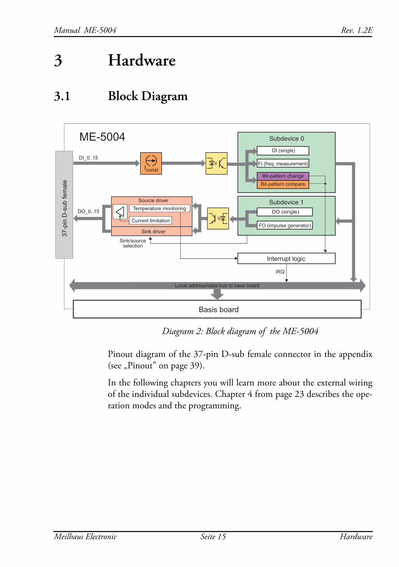
Diagram 2: Block diagram of the ME-5004
Pinout diagram of the 37-pin D-sub female connector in the appendix (see „Pinout” on page 39).
In the following chapters you will learn more about the external wiring of the individual subdevices. Chapter 4 from page 23 describes the ope-ration modes and the programming.
37-p
in D
-sub
fem
ale
IRQ
Local address/data bus to base board
Basis board
Interrupt logic
ME-5004ME-5810
Subdevice 0
Subdevice 1
FO (impulse generator)
Bit-pattern changeBit-pattern compare
FI (freq. measurement)
DI (single)DI_0..15
DO_0..15 Temperature monitoring
Current limitation
Source driver
Sink driver
DO (single)
Sink/sourceselection
Iconst
Meilhaus Electronic Seite 15 Hardware
Rev. 1.2E Manual ME-5004
3.2 ME-5004 cPCI/PCIe
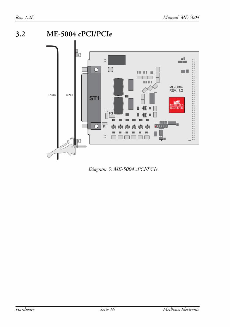
Diagram 3: ME-5004 cPCI/PCIe
ST1
ME-5004REV.: 1.2
cPCIPCIe
F3
F1
F2
Hardware Seite 16 Meilhaus Electronic
Manual ME-5004 Rev. 1.2E
3.3 Digital Input/Output The opto-isolated inputs and outputs have been designed for applications in industrial control applications (typ. 24 V). An external power supply (pin: VCC_EXT) is required for the opto-isolated digital outputs. De-pending on the application, the drivers of the output ports can be configured as sink or source or high impedance via software. The isola-tion voltage to PC-ground is 1000 VACRMS.
The plug-on board of type ME-5004 has 16 opto-isolated inputs and 16 opto-isolated outputs. Due to the opto-isolation, the port direction is fixed.
The programming of the various operating modes is described in chapter 4.1 from page 25.
3.3.1 Opto-isolated Inputs
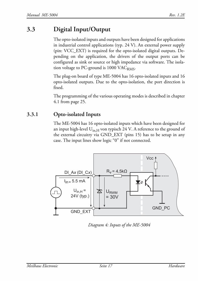
The ME-5004 has 16 opto-isolated inputs which have been designed for an input high-level Uin,H von typisch 24 V. A reference to the ground of the external circuitry via GND_EXT (pins 15) has to be setup in any case. The input lines show logic “0” if not connected.
Diagram 4: Inputs of the ME-5004
DI_Ax
GND_EXT
Uin,H =
Vcc
Iin = 5.5 mA
GND_PC
URWM= 30V24V (typ.)
Rv = 4,5kΩ(DI_Cx)
Meilhaus Electronic Seite 17 Hardware
Rev. 1.2E Manual ME-5004
The opto-isolated digital-inputs of the ME-5004 are protected from overvoltages with special Z-diodes, so called Transient Voltage Suppres-sor diodes (TVS diodes). These diodes can discharge short voltage pulses with URWM (Reverse Working Maximum) greater than 30 V to ground (max. 600 W pulse power at a pulse width of 1 ms).
3.3.2 Opto-isolated Outputs
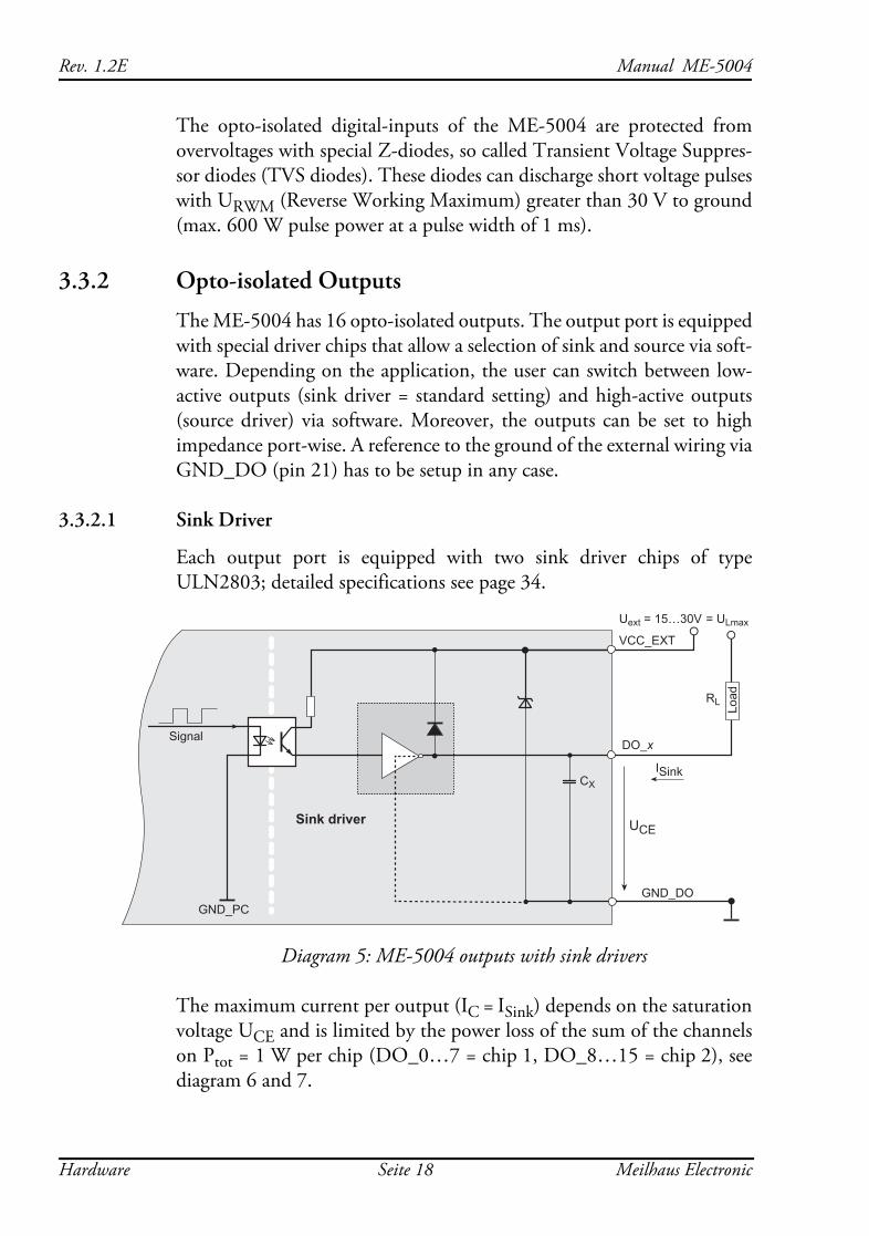
The ME-5004 has 16 opto-isolated outputs. The output port is equipped with special driver chips that allow a selection of sink and source via soft-ware. Depending on the application, the user can switch between low-active outputs (sink driver = standard setting) and high-active outputs (source driver) via software. Moreover, the outputs can be set to high impedance port-wise. A reference to the ground of the external wiring via GND_DO (pin 21) has to be setup in any case.
3.3.2.1 Sink Driver
Each output port is equipped with two sink driver chips of type ULN2803; detailed specifications see page 34.
Diagram 5: ME-5004 outputs with sink drivers
The maximum current per output (IC = ISink) depends on the saturation voltage UCE and is limited by the power loss of the sum of the channels on Ptot = 1 W per chip (DO_0…7 = chip 1, DO_8…15 = chip 2), see diagram 6 and 7.
VCC_EXT
= ULmax
GND_DOGND_PC
Signal
CX
Load
Sink driver
DO_x
ISink
Uext = 15…30V
RL
UCE
Hardware Seite 18 Meilhaus Electronic
Manual ME-5004 Rev. 1.2E
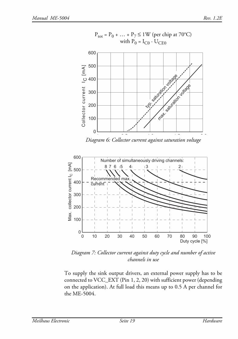
Ptot = P0 + … + P7 ≤ 1W (per chip at 70°C)with P0 = IC0 · UCE0
Diagram 6: Collector current against saturation voltage
Diagram 7: Collector current against duty cycle and number of active channels in use
To supply the sink output drivers, an external power supply has to be connected to VCC_EXT (Pin 1, 2, 20) with sufficient power (depending on the application). At full load this means up to 0.5 A per channel for the ME-5004.
Col
lect
or c
urre
nt
I C [
mA
]
00
600
500
400
300
200
100
2 01 51 00 5
max. s
aturat
ion vo
ltage
typ. s
aturat
ion vo
ltage
Max
. co
llect
or c
urre
nt I C
[m
A] Number of simultaneously driving channels:
8 7 6 5 4 3 2
00
600
500
400
300
200
100
100908070605040302010Duty cycle [%]
Recommended max.current
Meilhaus Electronic Seite 19 Hardware
Rev. 1.2E Manual ME-5004
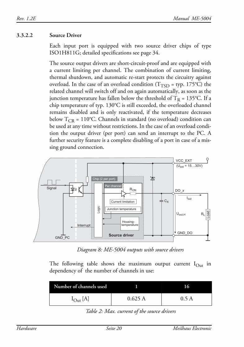
3.3.2.2 Source Driver
Each input port is equipped with two source driver chips of type ISO1H811G; detailed specifications see page 34.
The source output drivers are short-circuit-proof and are equipped with a current limiting per channel. The combination of current limiting, thermal shutdown, and automatic re-start protects the circuitry against overload. In the case of an overload condition (TTSD = typ. 175°C) the related channel will switch off and on again automatically, as soon as the junction temperature has fallen below the threshold of TR = 135°C. If a chip temperature of typ. 130°C is still exceeded, the overloaded channel remains disabled and is only reactivated, if the temperature decreases below TCR = 110°C. Channels in standard (no overload) condition can be used at any time without restrictions. In the case of an overload condi-tion the output driver (per port) can send an interrupt to the PC. A further security feature is a complete disabling of a port in case of a mis-sing ground connection.
Diagram 8: ME-5004 outputs with source drivers
The following table shows the maximum output current IOut in dependency of the number of channels in use:
Number of channels used 1 16
IOut [A] 0.625 A 0.5 A
Table 2: Max. current of the source drivers
VCC_EXT
DO_x
GND_DOGND_PC
Signal
Uout,H
(Uext = 15…30V)
IoutCurrent limitation CX
Load
InterruptHousing-temperature
Logi
c
Junction temperature
Per channel
Chip (2 per port)
Source driver
RON
RL
Hardware Seite 20 Meilhaus Electronic
Manual ME-5004 Rev. 1.2E
To supply the source output drivers, an external power source has to be connected to VCC_EXT (pins 1, 2, 20), with sufficient power (de-pending on the application). At full load this means up to 9 A for the ME-5004. The output voltage Uout,H can be calculated like this:
3.3.3 External Trigger
On the ME-5004 no external trigger inputs are available. However you can monitor the digital inputs on bit-pattern change and bit-pattern compare. As soon as the specified event occurs, an interrupt can be issued and passed directly to the PC. See chapter 4.2 on page 29.
3.4 Frequency Input/Output With the concept of “configurable subdevices” on the ME-5000 series boards you can use certain subdevices with an alternative functionality. The configuration tool ME-iDC is used to change the configuration before the user application is started.
The following channels are available:
• Frequency measurement (FI = “Frequency Input”): 8 independent inputs for measurement of frequency and duty cycle of periodic rectangular signals (max. 300 kHz).
• Pulse generator (FO = “Frequency Output”): 8 independent outputs for a periodic rectangular signal up to 3 kHz with a selectable duty cycle.
The related pins are marked with FI_x and FO_x in the pinout diagram on page 16. The remaining I/O-channels of the digital-ports cannot be used in this configuration.
Note: For the configuration “pulse generator” (FO) take care of the level at the unused pins DO_8..15. When used as sink drivers the outputs are in a high impedance state, when used as source drivers they are connected to ground!
The specifications of the digital-I/O ports also apply to the FI/FO lines. For all inputs and outputs a reference to the ground of the external wiring
Uout H, Uext RON Iout⋅( )–=
Meilhaus Electronic Seite 21 Hardware
Rev. 1.2E Manual ME-5004
has to be setup in any case. For the frequency measurement inputs this is the ground of the digital input section (GND_DI, pin 15) and for the pulse generator outputs this is the ground of the digital output section (GND_DO, pin 21)
The frequency counters and pulse generators are configured via software. Chapter 4.1.2 on page 26 describes the programming of the frequency-I/Os.
3.5 External Interrupt If required, you can monitor the bit-pattern of a digital input port. You can select one of the modes “bit-pattern change” and “bit-pattern compa-re”. As soon as the specified event occurs, an interrupt is issued and passed directly to the PC.
The digital inputs/outputs are programmed in the single operating mo-de. The interrupt handling is carried out with the meIOIrq… functions; see also chapter 4.2 on page 29.
Hardware Seite 22 Meilhaus Electronic
Manual ME-5004 Rev. 1.2E
4 ProgrammingThe Meilhaus Intelligent Driver System (ME-iDS) is included with the device for programming purposes. The ME-iDS is a unified driver system usable across devices and operating systems. It supports Windows 2000 and above, as well as Linux systems (in preparation) with Kernel 2.6 and above, and contains a universal function library (API) for all common programming languages. (You can find the scope of the current software support in the readme files of the ME-iDS.)
A detailed description of the functions can be found in the ME-iDS ma-nual (see the CD/DVD included with the board, or online under: www.meilhaus.com/download). Other details, such as the assignment of the subdevices and device-specific arguments, may be found in the help file (in the help file format under Windows, *.chm), which you can open via the "ME-iDS Control Center" in the information area of the taskbar (usually at the bottom right of the screen), or through the Windows Start menu.
The plug-on board of type ME-5004 is a discrete device with two "sub-devices", beginning with the index "0". The functionality of the subde-vices can be specified by the user through selecting a pre-defined configuration. The desired configuration is loaded into the board by the ME-iDC configuration tool before your application starts. Using the standard configuration, (ID 0), the board is ready to operate immedia-tely. You will find an overview of the currently available configurations in the following table:
Meilhaus Electronic Seite 23 Programming
Rev. 1.2E Manual ME-5004
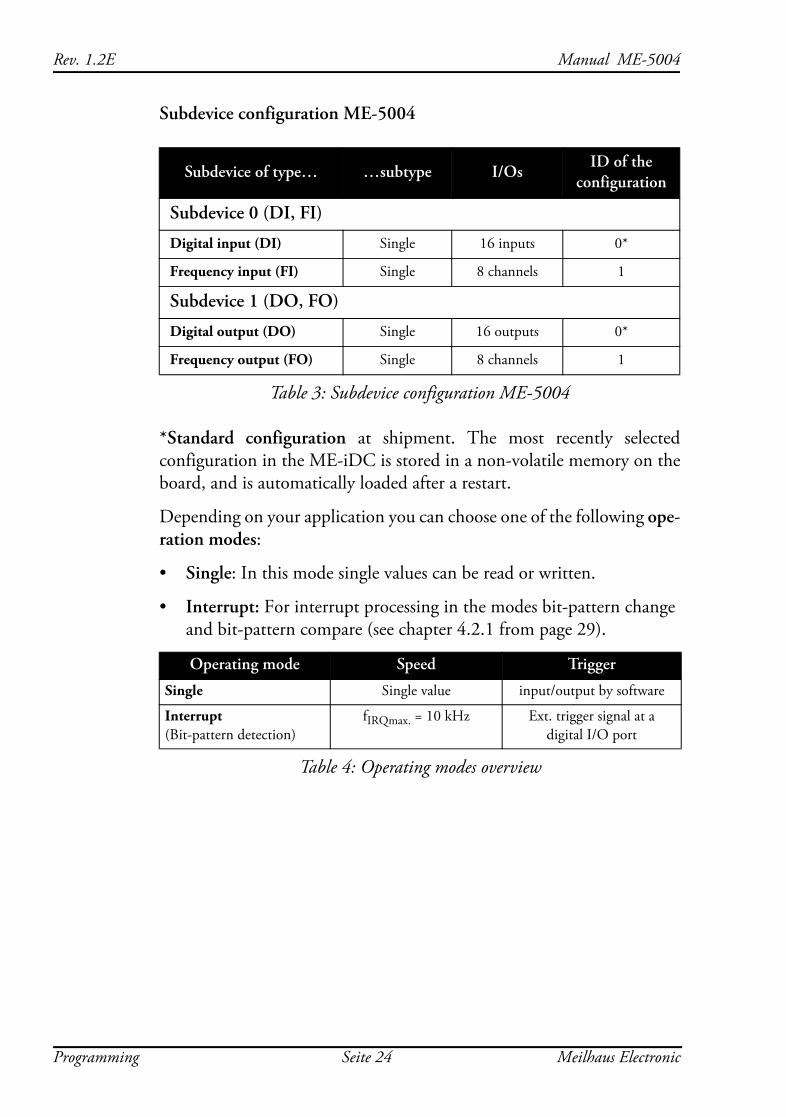
Subdevice configuration ME-5004
*Standard configuration at shipment. The most recently selected configuration in the ME-iDC is stored in a non-volatile memory on the board, and is automatically loaded after a restart.
Depending on your application you can choose one of the following ope-ration modes:
• Single: In this mode single values can be read or written.
• Interrupt: For interrupt processing in the modes bit-pattern change and bit-pattern compare (see chapter 4.2.1 from page 29).
Subdevice of type… …subtype I/OsID of the
configuration
Subdevice 0 (DI, FI)
Digital input (DI) Single 16 inputs 0*
Frequency input (FI) Single 8 channels 1
Subdevice 1 (DO, FO)
Digital output (DO) Single 16 outputs 0*
Frequency output (FO) Single 8 channels 1
Table 3: Subdevice configuration ME-5004
Operating mode Speed Trigger
Single Single value input/output by software
Interrupt (Bit-pattern detection)
fIRQmax. = 10 kHz Ext. trigger signal at a digital I/O port
Table 4: Operating modes overview
Programming Seite 24 Meilhaus Electronic
Manual ME-5004 Rev. 1.2E
4.1 Single Operation ModeIndividual values can be read or written in this operating mode.
Notes:
• The digital-I/O channels direction is determined by the ME-5004 series hardware (opto-couplers).
• In power-down state and after switching on the PC all outputs are in a high impedance state. Only if “1” is written, the output changes to conductive.
• A port that is configured as an output can also be read back!
4.1.1 Digital Input/Output
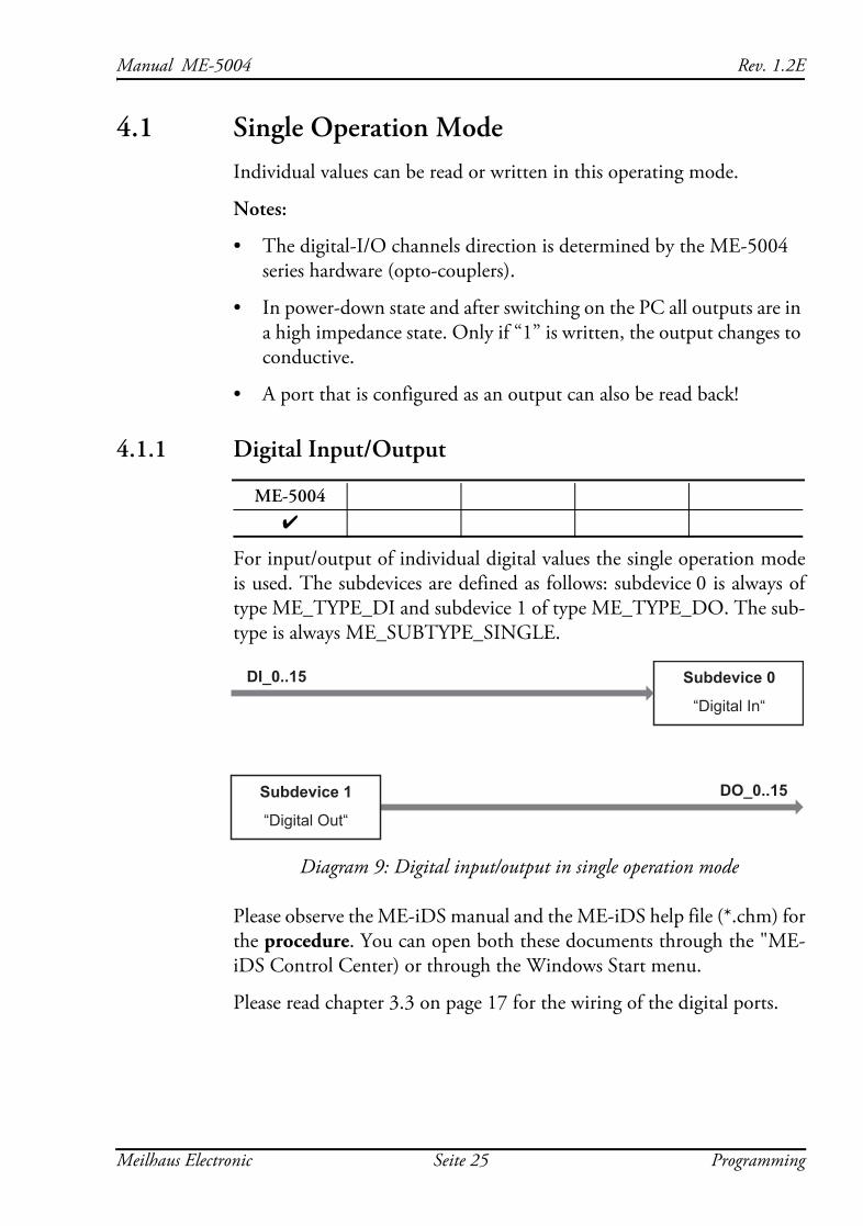
For input/output of individual digital values the single operation mode is used. The subdevices are defined as follows: subdevice 0 is always of type ME_TYPE_DI and subdevice 1 of type ME_TYPE_DO. The sub-type is always ME_SUBTYPE_SINGLE.
Diagram 9: Digital input/output in single operation mode
Please observe the ME-iDS manual and the ME-iDS help file (*.chm) for the procedure. You can open both these documents through the "ME-iDS Control Center) or through the Windows Start menu.
Please read chapter 3.3 on page 17 for the wiring of the digital ports.
ME-50044
Subdevice 0
“Digital In“
DI_0..15
DO_0..15 Subdevice 1
“Digital Out“
Meilhaus Electronic Seite 25 Programming
Rev. 1.2E Manual ME-5004
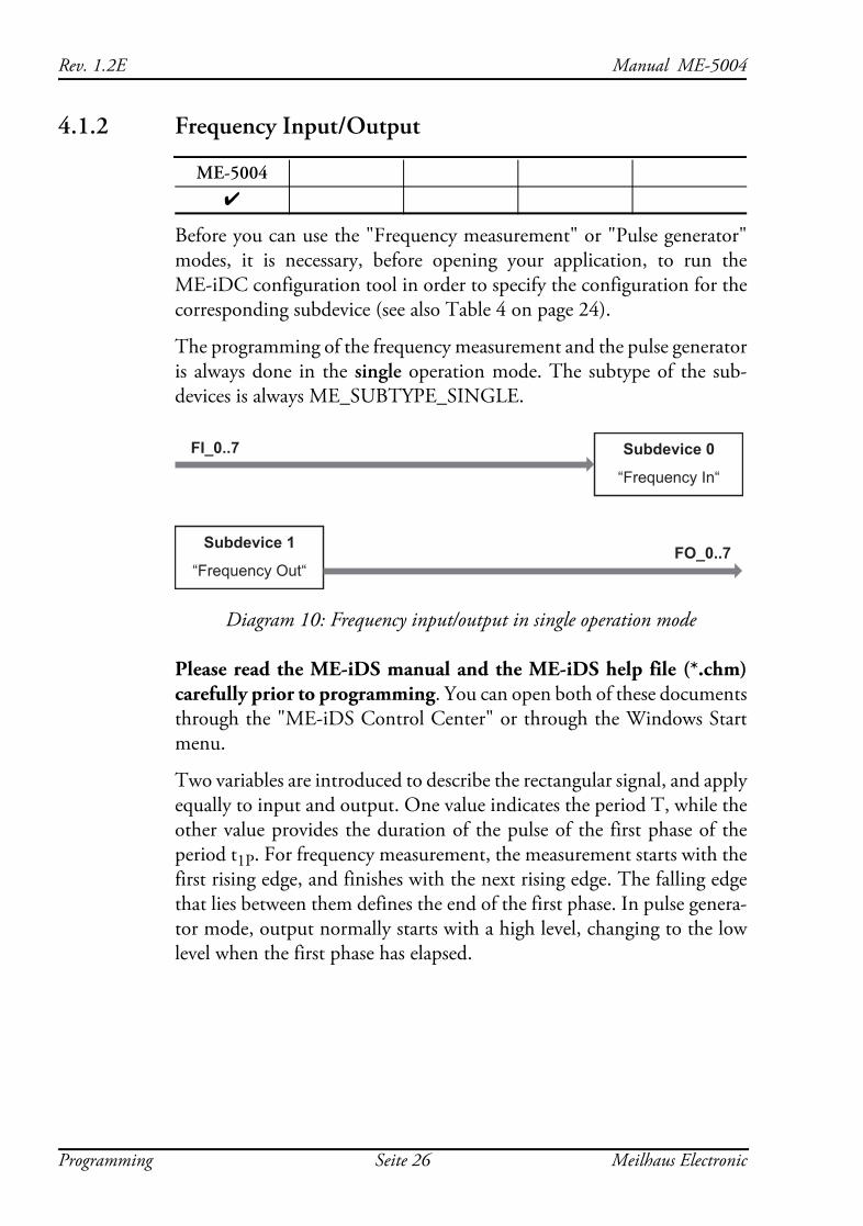
4.1.2 Frequency Input/Output
Before you can use the "Frequency measurement" or "Pulse generator" modes, it is necessary, before opening your application, to run the ME-iDC configuration tool in order to specify the configuration for the corresponding subdevice (see also Table 4 on page 24).
The programming of the frequency measurement and the pulse generator is always done in the single operation mode. The subtype of the sub-devices is always ME_SUBTYPE_SINGLE.
Diagram 10: Frequency input/output in single operation mode
Please read the ME-iDS manual and the ME-iDS help file (*.chm) carefully prior to programming. You can open both of these documents through the "ME-iDS Control Center" or through the Windows Start menu.
Two variables are introduced to describe the rectangular signal, and apply equally to input and output. One value indicates the period T, while the other value provides the duration of the pulse of the first phase of the period t1P. For frequency measurement, the measurement starts with the first rising edge, and finishes with the next rising edge. The falling edge that lies between them defines the end of the first phase. In pulse genera-tor mode, output normally starts with a high level, changing to the low level when the first phase has elapsed.
ME-50044
Subdevice 0
“Frequency In“
FI_0..7
Subdevice 1
“Frequency Out“FO_0..7
Programming Seite 26 Meilhaus Electronic
Manual ME-5004 Rev. 1.2E
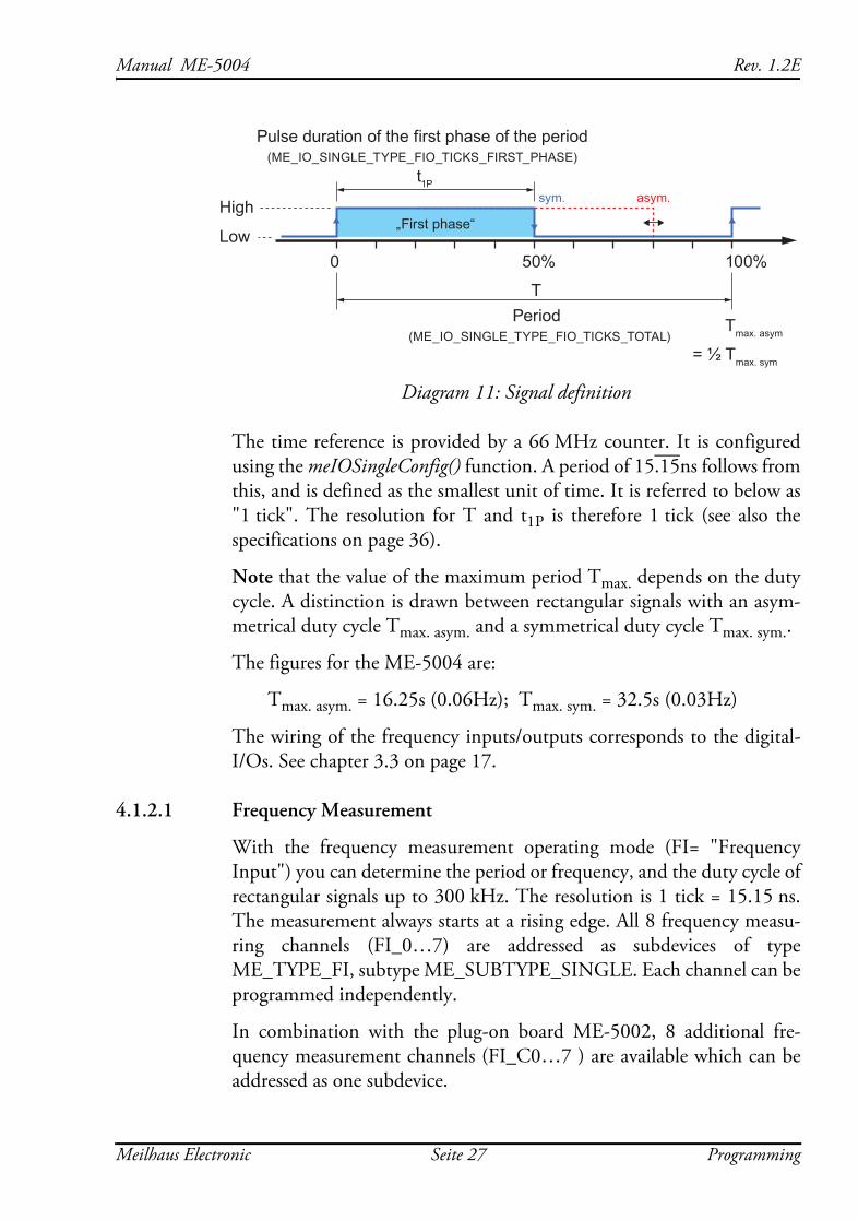
Diagram 11: Signal definition
The time reference is provided by a 66 MHz counter. It is configured using the meIOSingleConfig() function. A period of 15.15ns follows from this, and is defined as the smallest unit of time. It is referred to below as "1 tick". The resolution for T and t1P is therefore 1 tick (see also the specifications on page 36).
Note that the value of the maximum period Tmax. depends on the duty cycle. A distinction is drawn between rectangular signals with an asym-metrical duty cycle Tmax. asym. and a symmetrical duty cycle Tmax. sym..
The figures for the ME-5004 are:
Tmax. asym. = 16.25s (0.06Hz); Tmax. sym. = 32.5s (0.03Hz)
The wiring of the frequency inputs/outputs corresponds to the digital-I/Os. See chapter 3.3 on page 17.
4.1.2.1 Frequency Measurement
With the frequency measurement operating mode (FI= "Frequency Input") you can determine the period or frequency, and the duty cycle of rectangular signals up to 300 kHz. The resolution is 1 tick = 15.15 ns. The measurement always starts at a rising edge. All 8 frequency measu-ring channels (FI_0…7) are addressed as subdevices of type ME_TYPE_FI, subtype ME_SUBTYPE_SINGLE. Each channel can be programmed independently.
In combination with the plug-on board ME-5002, 8 additional fre-quency measurement channels (FI_C0…7 ) are available which can be addressed as one subdevice.
0
High
Tmax. asym
= ½ Tmax. sym
Low50% 100%
Period (ME_IO_SINGLE_TYPE_FIO_TICKS_TOTAL)
Pulse duration of the first phase of the period(ME_IO_SINGLE_TYPE_FIO_TICKS_FIRST_PHASE)
„First phase“
T
t1Psym. asym.
Meilhaus Electronic Seite 27 Programming
Rev. 1.2E Manual ME-5004
Note: If the frequency and duty cycle are the magnitudes you want, these can easily be calculated from the values returned for <pdTime>. The formula is:
Frequency [Hz] = 1/period [s]
Duty cycle [%] = ("duration of the first phase of the period" [s] / period [s]) × 100
4.1.2.2 Pulse Generator
In the pulse generator operating mode (FO = "Frequency Output") you can output rectangular signals with a variable duty cycle at frequencies of up to 3 kHz and with a resolution of 1 tick. All 8 pulse generator channels (FO_0…7) are addressed as subdevices of type ME_TYPE_FO, subtype ME_SUBTYPE_SINGLE. Each channel can be programmed independently.
The first phase of the rectangular signal is "high" by default. By setting the ME_IO_SINGLE_TYPE_FO_START_LOW flag it is also possible to start the output with a "low" level.
Note: An output channel can also be read back!
Programming Seite 28 Meilhaus Electronic
Manual ME-5004 Rev. 1.2E
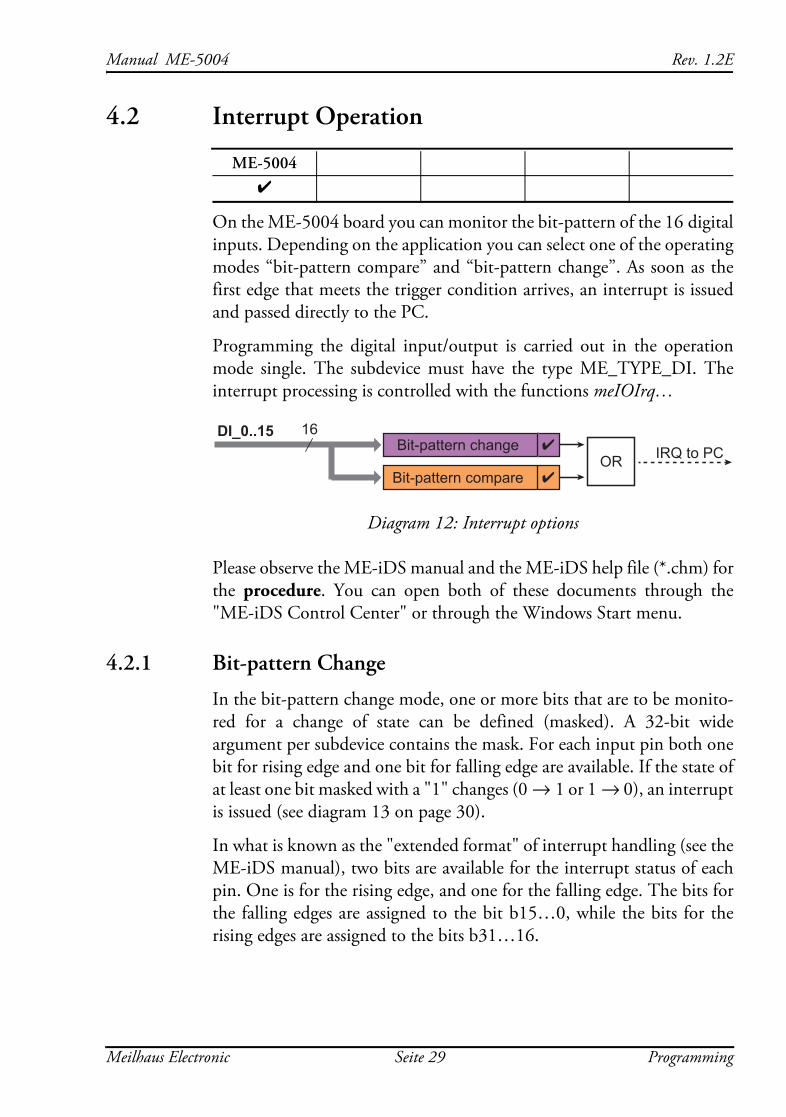
4.2 Interrupt Operation
On the ME-5004 board you can monitor the bit-pattern of the 16 digital inputs. Depending on the application you can select one of the operating modes “bit-pattern compare” and “bit-pattern change”. As soon as the first edge that meets the trigger condition arrives, an interrupt is issued and passed directly to the PC.
Programming the digital input/output is carried out in the operation mode single. The subdevice must have the type ME_TYPE_DI. The interrupt processing is controlled with the functions meIOIrq…
Diagram 12: Interrupt options
Please observe the ME-iDS manual and the ME-iDS help file (*.chm) for the procedure. You can open both of these documents through the "ME-iDS Control Center" or through the Windows Start menu.
4.2.1 Bit-pattern Change
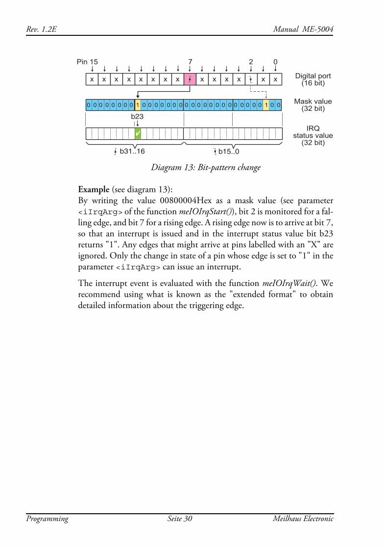
In the bit-pattern change mode, one or more bits that are to be monito-red for a change of state can be defined (masked). A 32-bit wide argument per subdevice contains the mask. For each input pin both one bit for rising edge and one bit for falling edge are available. If the state of at least one bit masked with a "1" changes (0 → 1 or 1 → 0), an interrupt is issued (see diagram 13 on page 30).
In what is known as the "extended format" of interrupt handling (see the ME-iDS manual), two bits are available for the interrupt status of each pin. One is for the rising edge, and one for the falling edge. The bits for the falling edges are assigned to the bit b15…0, while the bits for the rising edges are assigned to the bits b31…16.
ME-50044
IRQ to PCORBit-pattern change
16
Bit-pattern compare
DI_0..15
Meilhaus Electronic Seite 29 Programming
Rev. 1.2E Manual ME-5004
Diagram 13: Bit-pattern change
Example (see diagram 13): By writing the value 00800004Hex as a mask value (see parameter <iIrqArg> of the function meIOIrqStart()), bit 2 is monitored for a fal-ling edge, and bit 7 for a rising edge. A rising edge now is to arrive at bit 7, so that an interrupt is issued and in the interrupt status value bit b23 returns "1". Any edges that might arrive at pins labelled with an "X" are ignored. Only the change in state of a pin whose edge is set to "1" in the parameter <iIrqArg> can issue an interrupt.
The interrupt event is evaluated with the function meIOIrqWait(). We recommend using what is known as the "extended format" to obtain detailed information about the triggering edge.
Mask value(32 bit)
IRQstatus value
(32 bit)
Digital port(16 bit)
0 0 0 0 0 0 00 1 0 0 0 0 0 0 0 0 0 0 1 0 00 0 0 0 0 0 0 0 0 0
b23
Pin 15 7 2 0
x xxxxx xxxx xxx x
b31..16 b15..0
Programming Seite 30 Meilhaus Electronic
Manual ME-5004 Rev. 1.2E
4.2.2 Bit-pattern Compare
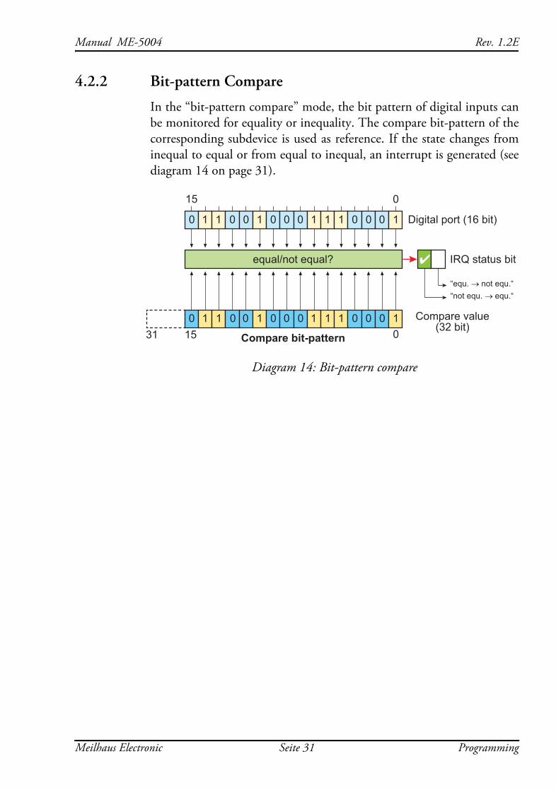
In the “bit-pattern compare” mode, the bit pattern of digital inputs can be monitored for equality or inequality. The compare bit-pattern of the corresponding subdevice is used as reference. If the state changes from inequal to equal or from equal to inequal, an interrupt is generated (see diagram 14 on page 31).
Diagram 14: Bit-pattern compare
1531 00 1 1 0 0 1 0 0 0 1 1 1 0 0 0 1
0 1 1 0 0 1 0 0 0 1 1 1 0 0 0 1
equal/not equal?
Compare bit-pattern
Compare value(32 bit)
Digital port (16 bit)
15 0
4 IRQ status bit
“equ. → not equ.““not equ. → equ.“
Meilhaus Electronic Seite 31 Programming
Rev. 1.2E Manual ME-5004
Programming Seite 32 Meilhaus Electronic
Manual ME-5004 Rev. 1.2E
Appendix
A Specifications(Ambient temperature 25 °C)
PC Interface via base board
Digital Input/Output (general)
Opto-isolated Inputs
Static valuesConditions: TA=25°C
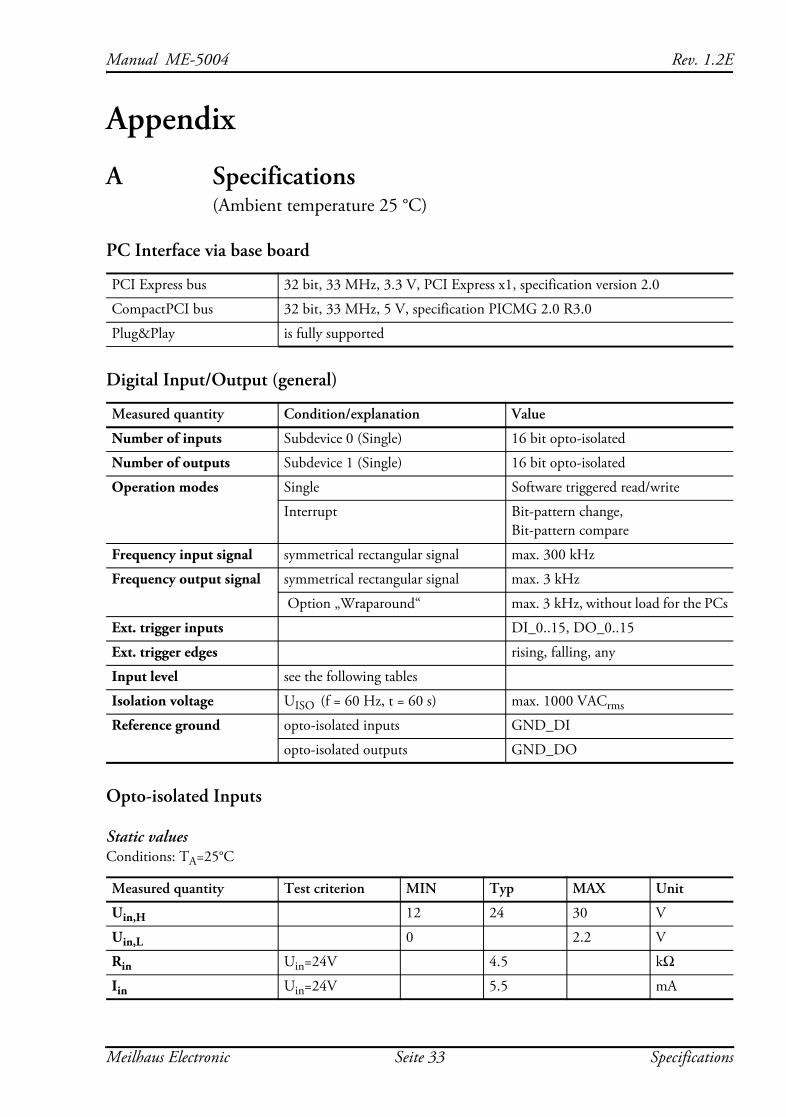
PCI Express bus 32 bit, 33 MHz, 3.3 V, PCI Express x1, specification version 2.0
CompactPCI bus 32 bit, 33 MHz, 5 V, specification PICMG 2.0 R3.0
Plug&Play is fully supported
Measured quantity Condition/explanation Value
Number of inputs Subdevice 0 (Single) 16 bit opto-isolated
Number of outputs Subdevice 1 (Single) 16 bit opto-isolated
Operation modes Single Software triggered read/write
Interrupt Bit-pattern change, Bit-pattern compare
Frequency input signal symmetrical rectangular signal max. 300 kHz
Frequency output signal symmetrical rectangular signal max. 3 kHz
Option „Wraparound“ max. 3 kHz, without load for the PCs
Ext. trigger inputs DI_0..15, DO_0..15
Ext. trigger edges rising, falling, any
Input level see the following tables
Isolation voltage UISO (f = 60 Hz, t = 60 s) max. 1000 VACrms
Reference ground opto-isolated inputs GND_DI
opto-isolated outputs GND_DO
Measured quantity Test criterion MIN Typ MAX Unit
Uin,H 12 24 30 V
Uin,L 0 2.2 V
Rin Uin=24V 4.5 kΩIin Uin=24V 5.5 mA
Meilhaus Electronic Seite 33 Specifications
Rev. 1.2E Manual ME-5004
Limiting values
Opto-isolated OutputsConditions: TA=25°C
Sink Driver (UDN2803)
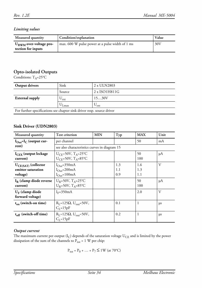
Output currentThe maximum current per output (IC) depends of the saturation voltage UCE and is limited by the power dissipation of the sum of the channels to Ptot = 1 W per chip:
Ptot = P0 + … + P7 ≤ 1W (at 70°C)
Measured quantity Condition/explanation Value
URWM over-voltage pro-tection for inputs
max. 600 W pulse power at a pulse width of 1 ms 30V
Output drivers Sink 2 x ULN2803
Source 2 x ISO1H811G
External supply Uext 15…30V
ULmax Uext
For further specifications see chapter sink driver resp. source driver
Measured quantity Test criterion MIN Typ MAX Unit
IOut=IC (output cur-rent)
per channel 50 mA
see also characteristics curves in diagram 15
ICEX (output leckage current)
UCE=50V, TA=25°C UCE=50V, TA=85°C
50 100
μA
UCE(SAT) (collector emitter saturation voltage)
IOut=350mA IOut=200mA IOut=100mA
1.3 1.1 0.9
1.6 1.3 1.1
V
IR (clamp diode reverse current)
UR=50V, TA=25°C UR=50V, TA=85°C
50 100
μA
UF (clamp diode forward voltage)
IF=350mA 2.0 V
ton (switch-on time) RL=125Ω, Uout=50V, CL=15pF
0.1 1 μs
toff (switch-off time) RL=125Ω, Uout=50V, CL=15pF
0.2 1 μs
Specifications Seite 34 Meilhaus Electronic
Manual ME-5004 Rev. 1.2E
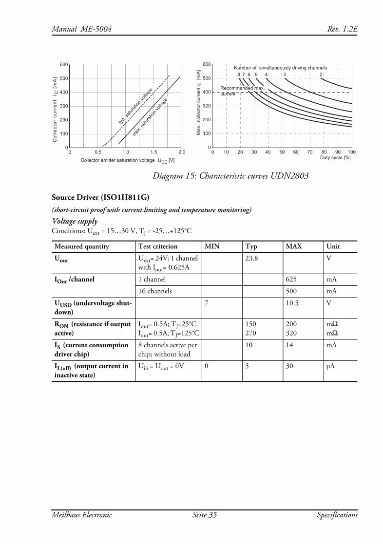
Diagram 15: Characteristic curves UDN2803
Source Driver (ISO1H811G)(short-circuit proof with current limiting and temperature monitoring)
Voltage supplyConditions: Uext = 15…30 V, TJ = -25…+125°C
Measured quantity Test criterion MIN Typ MAX Unit
Uout Uext= 24V; 1 channel with Iout= 0.625A
23.8 V
IOut /channel 1 channel 625 mA
16 channels 500 mA
UUSD (undervoltage shut-down)
7 10.5 V
RON (resistance if output active)
Iout= 0.5A; TJ=25°C Iout= 0.5A; TJ=125°C
150 270
200 320
mΩ mΩ
IS (current consumption driver chip)
8 channels active per chip; without load
10 14 mA
IL(off) (output current in inactive state)
Uin = Uout = 0V 0 5 30 μA
Col
lect
or c
urre
nt
I C [
mA
]
00
600
500
400
300
200
100
2.01.51.00.5
Collector emitter saturation voltage UCE [V]
max. s
aturat
ion vo
ltage
typ. s
aturat
ion vo
ltage
Max
. co
llect
or c
urre
nt I C
[m
A] Number of simultaneously driving channels
8 7 6 5 4 3 2
00
600
500
400
300
200
100
100908070605040302010Duty cycle [%]
Recommended max.current
Meilhaus Electronic Seite 35 Specifications
Rev. 1.2E Manual ME-5004
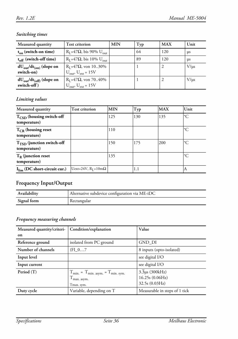
Switching times
Limiting values
Frequency Input/Output
Frequency measuring channels
Measured quantity Test criterion MIN Typ MAX Unit
ton (switch-on time) RL=47Ω, bis 90% Uout 64 120 μs
toff (switch-off time) RL=47Ω, bis 10% Uout 89 120 μs
dUout/dt(on) (slope on switch-on)
RL=47Ω, von 10..30% Uout, Uext = 15V
1 2 V/μs
dUout/dt(off) (slope on switch-off )
RL=47Ω, von 70..40% Uout, Uext = 15V
1 2 V/μs
Measured quantity Test criterion MIN Typ MAX Unit
TCSD (housing switch-off temperature)
125 130 135 °C
TCR (housing reset temperature)
110 °C
TTSD (junction switch-off temperature)
150 175 200 °C
TR (junction reset temperature)
135 °C
Ilim (DC short-circuit cur.) Uext=24V, RL=10mΩ 1.1 A
Availability Alternative subdevice configuration via ME-iDC
Signal form Rectangular
Measured quantity/criteri-on
Condition/explanation Value
Reference ground isolated from PC ground GND_DI
Number of channels (FI_0…7 8 inputs (opto-isolated)
Input level see digital I/O
Input current see digital I/O
Period (T) Tmin. = Tmin. asym. = Tmin. sym. Tmax. asym. Tmax. sym.
3.3μs (300kHz) 16.25s (0.06Hz) 32.5s (0.03Hz)
Duty cycle Variable, depending on T Measurable in steps of 1 tick
Specifications Seite 36 Meilhaus Electronic
Manual ME-5004 Rev. 1.2E
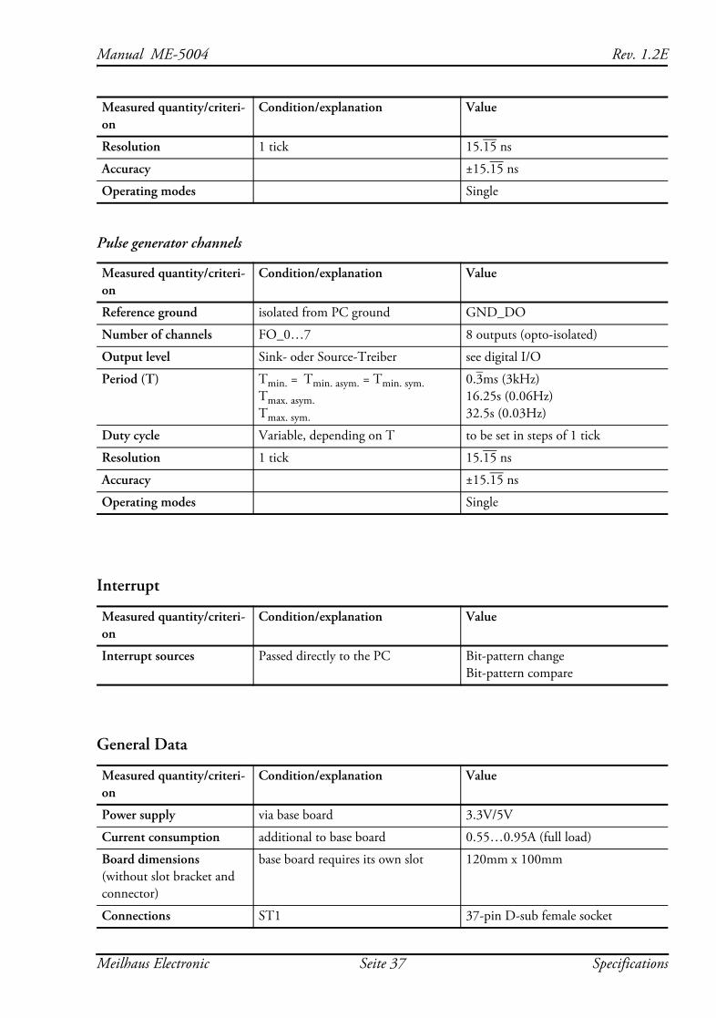
Pulse generator channels
Interrupt
General Data
Resolution 1 tick 15.15 ns
Accuracy ±15.15 ns
Operating modes Single
Measured quantity/criteri-on
Condition/explanation Value
Reference ground isolated from PC ground GND_DO
Number of channels FO_0…7 8 outputs (opto-isolated)
Output level Sink- oder Source-Treiber see digital I/O
Period (T) Tmin. = Tmin. asym. = Tmin. sym. Tmax. asym. Tmax. sym.
0.3ms (3kHz) 16.25s (0.06Hz) 32.5s (0.03Hz)
Duty cycle Variable, depending on T to be set in steps of 1 tick
Resolution 1 tick 15.15 ns
Accuracy ±15.15 ns
Operating modes Single
Measured quantity/criteri-on
Condition/explanation Value
Interrupt sources Passed directly to the PC Bit-pattern change Bit-pattern compare
Measured quantity/criteri-on
Condition/explanation Value
Power supply via base board 3.3V/5V
Current consumption additional to base board 0.55…0.95A (full load)
Board dimensions (without slot bracket and connector)
base board requires its own slot 120mm x 100mm
Connections ST1 37-pin D-sub female socket
Measured quantity/criteri-on
Condition/explanation Value
Meilhaus Electronic Seite 37 Specifications
Rev. 1.2E Manual ME-5004
CE Certification
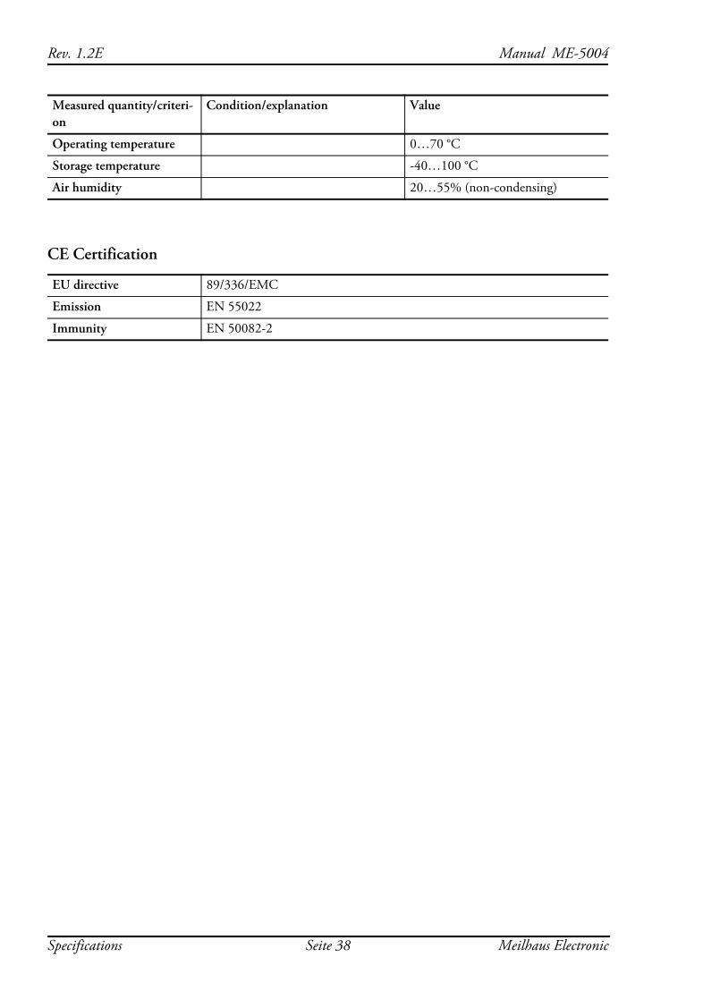
Operating temperature 0…70 °C
Storage temperature -40…100 °C
Air humidity 20…55% (non-condensing)
EU directive 89/336/EMC
Emission EN 55022
Immunity EN 50082-2
Measured quantity/criteri-on
Condition/explanation Value
Specifications Seite 38 Meilhaus Electronic
Manual ME-5004 Rev. 1.2E
B Pinout
Legend for pinouts:
DI_0..15 Digital inputs (subdevice 0)
DO_0..15 Digital outputs (subdevice 1)
FI_0..7 Frequency measurement inputs (alternative configuration)
FO_0..7 Pulse generator outputs (alternative configuration)
VCC_EXT VCC input for ext. power supply of isolated inputs and out-puts, Uext typ. 24 VDC
GND_DI Reference ground for isolated inputs (isolated from outputs and PC ground)
GND_DO Reference ground for isolated outputs (isolated from inputs and PC ground)
Note: In the configuration “pulse generator” (FO) don’t forget to take care of the unused pins DO_8..15. When used as sink drivers they are in high impedance state, when used as source drivers they are connected to ground!
Meilhaus Electronic Seite 39 Pinout
Rev. 1.2E Manual ME-5004
B1 37-pin D-Sub (ST1)
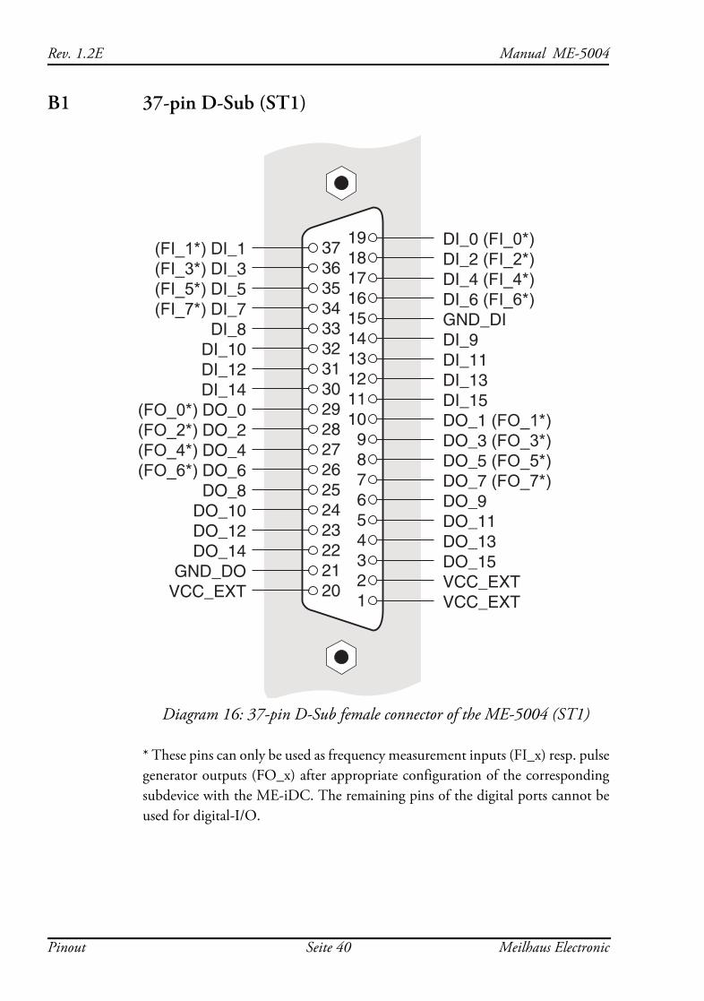
Diagram 16: 37-pin D-Sub female connector of the ME-5004 (ST1)
* These pins can only be used as frequency measurement inputs (FI_x) resp. pulse generator outputs (FO_x) after appropriate configuration of the corresponding subdevice with the ME-iDC. The remaining pins of the digital ports cannot be used for digital-I/O.
DI_0 (FI_0*)DI_2 (FI_2*)DI_4 (FI_4*)DI_6 (FI_6*)GND_DIDI_9DI_11DI_13DI_15DO_1 (FO_1*)DO_3 (FO_3*)DO_5 (FO_5*)DO_7 (FO_7*)DO_9DO_11DO_13DO_15VCC_EXTVCC_EXT
19181716151413121110987654321
373635343332313029282726252423222120
(FI_1*) DI_1 (FI_3*) DI_3 (FI_5*) DI_5 (FI_7*) DI_7
DI_8DI_10DI_12DI_14
(FO_0*) DO_0(FO_2*) DO_2(FO_4*) DO_4(FO_6*) DO_6
DO_8DO_10DO_12DO_14
GND_DOVCC_EXT
Pinout Seite 40 Meilhaus Electronic
Manual ME-5004 Rev. 1.2E
C AccessoriesWe recommend the use of high-quality connecting cables with a largely calculated cable cross-section.
ME-AB-D37M
Terminal block with 37-pin D-sub male connector
ME-AK-D37
Connecting cable (1:1) from 37-pin D-Sub male connector to 37-pin D-Sub female connector
Further accessories can be found in the current Meilhaus Electronic catalogue, or on the Internet under www.meilhaus.de
Meilhaus Electronic Seite 41 Accessories
Rev. 1.2E Manual ME-5004
D Technical Questions
D1 HotlineIf you should have any technical questions or problems that can be put down to your Meilhaus device, please send a fax to our hotline:
Fax hotline: + 49 (0) 89/89 01 66 28 eMail: [email protected]
Please give a full description of the problems and as much information as possible, including operating system information.
D2 Service address
If a technical error should occur with your device please contact us at the following address:
Meilhaus Electronic GmbH
Service Department Fischerstraße 2 D-82178 Puchheim/Germany
If you want to send back a device to be repaired it is strictly necessary to request for a RMA number and to follow the notes to deal with the RMA process. Please attach a detailed error description of the problem, inclu-ding information about operating system and application software!
D3 Driver Update
The current driver versions for Meilhaus devices and our manuals in PDF format are available under www.meilhaus.com.
Technical Questions Seite 42 Meilhaus Electronic
Manual ME-5004 Rev. 1.2E
E Index
AAccessories 41
BBit-pattern change 29Bit-pattern compare 31Block diagram 15
DDigital input/output
Programming 25Wiring 17
Driver Update 42D-Sub connector 40
EExternal interrupt 22External trigger 21
FFeatures 8Frequency input/output
Programming 26Wiring 21
Frequency measurement 21, 27H
Hardware description 15I
InterruptProgramming 29Wiring 22
Introduction 5O
Operation modesFrequency measurement 27Interrupt 29Pulse generator 28Single operation 25
Opto-isolated inputs 17Opto-isolated outputs 18
Meilhaus Electronic Seit
PPinout 39Programming
Bit-pattern change 29Bit-pattern compare 31Counter 26Frequency input/output 26Interrupt 29Single operation 25
Pulse generator 21, 28S
Scope of supply 7Service and Support 42Single operation 25Sink driver 18Software support 10Source driver 20Specifications 33System requirements 10
TTest program 11
WWarnings 5Wiring
of digital inputs 17of digital outputs 18
e 43 Index
Rev. 1.2E Manual ME-5004
Index Seit
e 44 Meilhaus Electronic


![3] 5004 UNIVERSIDAD SALESIANA 2,](https://img.pdfslide.net/doc/110x75/62df161a8b723e73e25f7fdf/3-5004-universidad-salesiana-2.jpg)