Embed Size (px)
Citation preview

CNCC6/C64/C64T
PROGRAMMING MANUAL(LATHE TYPE)
BNP-B2264D(ENG)

MELDAS is a registered trademark of Mitsubishi Electric Corporation. Other company and product names that appear in this manual are trademarks or registered trademarks of the respective company.

I
Introduction This manual is a guide for using the MELDAS C6/C64/C64T. Programming is described in this manual, so read this manual thoroughly before starting programming. Thoroughly study the "Precautions for Safety" on the following page to ensure safe use of this NC unit. Details described in this manual
CAUTION
For items described as "Restrictions" or "Usable State" in this manual, the instruction manual issued by the machine manufacturer takes precedence over this manual.
Items not described in this manual must be interpreted as "not possible". This manual is written on the assumption that all option functions are added.
Refer to the specifications issued by the machine manufacturer before starting use. Refer to the Instruction Manual issued by each machine manufacturer for details on each machine tool.
Some screens and functions may differ depending on the NC system (or its version), and some functions may not be possible. Please confirm the specifications before use.
General precautions (1) Refer to the following documents for details on handling MELDAS C6/C64/C64T Instruction Manual ................................. BNP-B2259

II
Precautions for Safety Always read the specifications issued by the machine maker, this manual, related manuals and attached documents before installation, operation, programming, maintenance or inspection to ensure correct use. Understand this numerical controller, safety items and cautions before using the unit. This manual ranks the safety precautions into "DANGER", "WARNING" and "CAUTION".
When the user may be subject to imminent fatalities or major injuries if handling is mistaken. When the user may be subject to fatalities or major injuries if handling is mistaken. When the user may be subject to injuries or when physical damage may occur if handling is mistaken.
Note that even items ranked as " CAUTION", may lead to major results depending on the situation. In any case, important information that must always be observed is described.
DANGER
Not applicable in this manual.
WARNING
Not applicable in this manual.
CAUTION
1. Items related to product and manual For items described as "Restrictions" or "Usable State" in this manual, the instruction manual issued by the machine manufacturer takes precedence over this manual.
Items not described in this manual must be interpreted as "not possible". This manual is written on the assumption that all option functions are added. Refer to the specifications issued by the machine manufacturer before starting use.
Refer to the Instruction Manual issued by each machine manufacturer for details on each machine tool.
Some screens and functions may differ depending on the NC system (or its version), and some functions may not be possible. Please confirm the specifications before use.
DANGER
WARNING
CAUTION

III
CAUTION
2. Items related to operation Before starting actual machining, always carry out dry run operation to confirm the machining program, tool offset amount and workpiece offset amount, etc.
If the workpiece coordinate system offset amount is changed during single block stop, the new setting will be valid from the next block.
Turn the mirror image ON and OFF at the mirror image center. If the tool offset amount is changed during automatic operation (including during single block stop), it will be validated from the next block or blocks onwards.
Do not make the synchronous spindle rotation command OFF with one workpiece chucked by the basic spindle and synchronous spindle during the spindle synchronous control mode. Failure to observe this may cause the synchronous spindle stop, and hazardous situation.
3. Items related to programming The commands with "no value after G" will be handled as "G00". ";" "EOB" and "%" "EOR" are expressions used for explanation. The actual codes are: For ISO: "CR, LF", or "LF" and "%".
Programs created on the Edit screen are stored in the NC memory in a "CR, LF" format, but programs created with external devices such as the FLD or RS-232C may be stored in an "LF" format.
The actual codes for EIA are: "EOB (End of Block)" and "EOR (End of Record)". When creating the machining program, select the appropriate machining conditions, and make sure that the performance, capacity and limits of the machine and NC are not exceeded. The examples do not consider the machining conditions.
Do not change fixed cycle programs without the prior approval of the machine manufacturer.
When programming the multi-part system, take special care to the movements of the programs for other part systems.
i
Contents 1. Control Axes .............................................................................................................................. 1
1.1 Coordinate word and control axis........................................................................................ 1 1.2 Coordinate systems and coordinate zero point symbols.................................................... 2
2. Input Command Units............................................................................................................... 3 2.1 Input command units ........................................................................................................... 3 2.2 Input setting units................................................................................................................. 3
3. Data Formats.............................................................................................................................. 4 3.1 Tape codes .......................................................................................................................... 4 3.2 Program formats.................................................................................................................. 7 3.3 Program address check function......................................................................................... 9 3.4 Tape memory format ......................................................................................................... 10 3.5 Optional block skip ; / ........................................................................................................ 10 3.6 Program/sequence/block numbers; O, N.......................................................................... 11 3.7 Parity H/V........................................................................................................................... 12 3.8 G code lists ........................................................................................................................ 13 3.9 Precautions before starting machining.............................................................................. 17
4. Buffer Register......................................................................................................................... 18 4.1 Pre-read buffers................................................................................................................. 18
5. Position Commands ............................................................................................................... 19 5.1 Incremental/absolute value commands ............................................................................ 19 5.2 Radius/diameter commands ............................................................................................. 20 5.3 Inch/metric conversion; G20, G21..................................................................................... 21 5.4 Decimal point input ............................................................................................................ 22
6. Interpolation Functions .......................................................................................................... 26 6.1 Positioning (Rapid Traverse); G00.................................................................................... 26 6.2 Linear interpolation; G01 ................................................................................................... 32 6.3 Circular Interpolation; G02, G03 ....................................................................................... 35 6.4 R specification circular interpolation; G02, G03................................................................ 39 6.5 Plane selection; G17, G18, G19 ....................................................................................... 41 6.6 Thread cutting.................................................................................................................... 43
6.6.1 Constant lead thread cutting; G33............................................................................. 43 6.6.2 Inch thread cutting; G33 ............................................................................................ 47 6.6.3 Continuous thread cutting.......................................................................................... 48 6.6.4 Variable lead thread cutting; G34.............................................................................. 49
7. Feed Functions........................................................................................................................ 51 7.1 Rapid traverse rate ............................................................................................................ 51 7.2 Cutting feedrate ................................................................................................................. 51 7.3 F1-digit feed....................................................................................................................... 52 7.4 Synchronous/asynchronous feed; G94, G95.................................................................... 54 7.5 Feedrate designation and effects on control axes............................................................ 56 7.6 Thread cutting mode.......................................................................................................... 60 7.7 Automatic acceleration/deceleration ................................................................................. 61 7.8 Speed clamp...................................................................................................................... 61 7.9 Exact stop check; G09 ...................................................................................................... 62 7.10 Exact stop check mode ; G61 ......................................................................................... 65 7.11 Automatic corner override ; G62 ..................................................................................... 66 7.12 Tapping mode ; G63........................................................................................................ 71 7.13 Cutting mode ; G64 ......................................................................................................... 71
8. Dwell ......................................................................................................................................... 72 8.1 Per-second dwell ; G04 ..................................................................................................... 72

ii
9. Miscellaneous Functions ....................................................................................................... 74 9.1 Miscellaneous functions (M8-digits BCD) ......................................................................... 74 9.2 2nd miscellaneous functions (A8-digits, B8-digits or C8-digits) ....................................... 76
10. Spindle Functions ................................................................................................................. 77 10.1 Spindle function (S2-digits BCD) ..... During standard PLC specifications .................... 77 10.2 Spindle function (S6-digits Analog) ................................................................................. 77 10.3 Spindle functions (S8-digits)............................................................................................ 78 10.4 Multiple spindle control I .................................................................................................. 79
10.4.1 Multiple spindle control ............................................................................................ 79 10.4.2 Spindle selection command .................................................................................... 80
10.5 Constant surface speed control; G96, G97 .................................................................... 82 10.6 Spindle clamp speed setting; G92 .................................................................................. 83 10.7 Spindle synchronous control I; G114.1 ........................................................................... 84 10.8 Spindle synchronization control II ................................................................................... 92
11. Tool Functions....................................................................................................................... 99 11.1 Tool functions (T8-digits BCD) ........................................................................................ 99
12. Tool Offset Functions ......................................................................................................... 100 12.1 Tool offset ...................................................................................................................... 100
12.1.1 Tool offset start ...................................................................................................... 101 12.2 Tool length offset ........................................................................................................... 102 12.3 Tool nose wear offset .................................................................................................... 104 12.4 Tool nose radius compensation; G40, G41, G42, G46 ................................................ 105
12.4.1 Tool nose point and compensation directions....................................................... 107 12.4.2 Tool nose radius compensation operations .......................................................... 110 12.4.3 Other operations during tool nose radius compensation ...................................... 127 12.4.4 G41/G42 commands and I, J, K designation ........................................................ 135 12.4.5 Interrupts during tool nose radius compensation.................................................. 140 12.4.6 General precautions for tool nose radius compensation ...................................... 142 12.4.7 Interference check ................................................................................................. 143
12.5 Programmed offset input; G10 ...................................................................................... 149 12.6 Tool life management II................................................................................................. 152
12.6.1 Counting the tool life .............................................................................................. 155 13. Program Support Functions .............................................................................................. 157
13.1 Fixed cycles for turning ................................................................................................. 157 13.1.1 Longitudinal cutting cycle; G77 ............................................................................. 158 13.1.2 Thread cutting cycle; G78...................................................................................... 160 13.1.3 Face cutting cycle; G79......................................................................................... 163
13.2 Compound type fixed cycles ......................................................................................... 166 13.2.1 Longitudinal rough cutting cycle; G71 ................................................................... 167 13.2.2 Face rough cutting cycle; G72............................................................................... 171 13.2.3 Formed material rough cutting cycle; G73 ............................................................ 175 13.2.4 Finishing cycle; G70 .............................................................................................. 179 13.2.5 Face cut-off cycle; G74.......................................................................................... 180 13.2.6 Longitudinal cut-off cycle; G75 .............................................................................. 182 13.2.7 Compound type thread cutting cycle; G76............................................................ 184 13.2.8 Precautions for compound type fixed cycles; G70 ~ G76 .................................... 188
13.3 Hole drilling fixed cycles; G80 ~ G89 ............................................................................ 190 13.3.1 Face deep hole drilling cycle 1; G83
(Longitudinal deep hole drilling cycle 1; G87) ...................................................... 195 13.3.2 Face tapping cycle; G84 (Longitudinal tapping cycle; G88) ................................. 196 13.3.3 Face boring cycle; G85 (Longitudinal boring cycle; G89)..................................... 199 13.3.4 Deep hole drilling cycle 2; G83.2........................................................................... 199 13.3.5 Hole drilling fixed cycle cancel; G80 ..................................................................... 202 13.3.6 Precautions when using a hole drilling fixed cycle................................................ 202
13.4 Subprogram control; M98, M99..................................................................................... 204 13.4.1 Calling subprogram with M98 and M99 commands ............................................. 204

iii
13.5 Variable commands....................................................................................................... 209 13.6 User macro .................................................................................................................... 212
13.6.1 User macro commands; G65, G66, G66.1, G67 .................................................. 212 13.6.2 Macro call instruction............................................................................................. 213 13.6.3 Variables ................................................................................................................ 221 13.6.4 Types of variables.................................................................................................. 223 13.6.5 Operation commands ............................................................................................ 251 13.6.6 Control commands ................................................................................................ 257 13.6.7 External output commands.................................................................................... 260 13.6.8 Precautions............................................................................................................ 262
13.7 Corner chamfering/corner rounding I ............................................................................ 264 13.7.1 Corner chamfering ",C".......................................................................................... 264 13.7.2 Corner rounding ",R_" ........................................................................................... 266 13.7.3 Interrupt during corner chamfering/corner rounding ............................................. 267
13.8 Corner chamfering/corner rounding II ........................................................................... 269 13.8.1 Corner chamfering ",C_"........................................................................................ 269 13.8.2 Corner rounding ",R_" ........................................................................................... 271 13.8.3 Interrupt during corner chamfering/corner rounding ............................................. 272
13.9 Geometric ...................................................................................................................... 273 13.9.1 Geometric I ............................................................................................................ 273 13.9.2 Geometric IB.......................................................................................................... 276
13.10 Program parameter input; G10, G11 .......................................................................... 290 13.11 Macro interrupt ; M96, M97 ......................................................................................... 291 13.12 Tool change position return; G30.1 ~ G30.5 .............................................................. 299 13.13 Double-turret mirror image .......................................................................................... 302 13.14 Synchronizing operation between part systems ......................................................... 307 13.15 Start Point Designation Synchronizing (Type 1); G115.............................................. 312 13.16 Start Point Designation Synchronizing (Type 2); G116.............................................. 314 13.17 Balance cut .................................................................................................................. 317 13.18 2-part system simultaneous thread cutting cycle........................................................ 320
13.18.1 Parameter setting command ............................................................................... 320 13.18.2 2-part system simultaneous thread cutting cycle I ; G76.1................................. 321 13.18.3 2-part system simultaneous thread cutting cycle II ; G76.2................................ 323
13.19 Miscellaneous function output during axis movement; G117..................................... 326 14. Coordinate System Setting Functions ............................................................................. 328
14.1 Coordinate words and control axes .............................................................................. 328 14.2 Basic machine, workpiece and local coordinate systems ............................................ 329 14.3 Machine zero point and 2nd, 3rd, and 4th reference points (Zero point) ..................... 330 14.4 Automatic coordinate system setting ............................................................................ 331 14.5 Machine coordinate system selection; G53 .................................................................. 332 14.6 Coordinate system setting; G92.................................................................................... 333 14.7 Reference point (Zero point) return; G28, G29............................................................. 334 14.8 2nd, 3rd, and 4th reference point (Zero point) return; G30 .......................................... 338 14.9 Reference point check; G27.......................................................................................... 341 14.10 Workpiece coordinate system setting and offset; G54 ~ G59.................................... 342 14.11 Local coordinate system setting; G52......................................................................... 347
15. Protection Function ............................................................................................................ 348 15.1 Chuck barrier/tailstock barrier; G22, G23 ..................................................................... 348
16. Measurement Support Functions...................................................................................... 351 16.1 Automatic tool length measurement; G37 .................................................................... 351 16.2 Skip function; G31 ......................................................................................................... 355 16.3 Multi-stage skip function; G31.n, G04........................................................................... 361 16.4 Multi-stage skip function 2 ; G31................................................................................... 363
Appendix 1. Program Parameter Input N No. Correspondence Table............................... A-1 Appendix 2. Program Error ..................................................................................................... A-6
1. Control Axes 1.1 Coordinate word and control axis
1
1. Control Axes 1.1 Coordinate word and control axis
Function and purpose
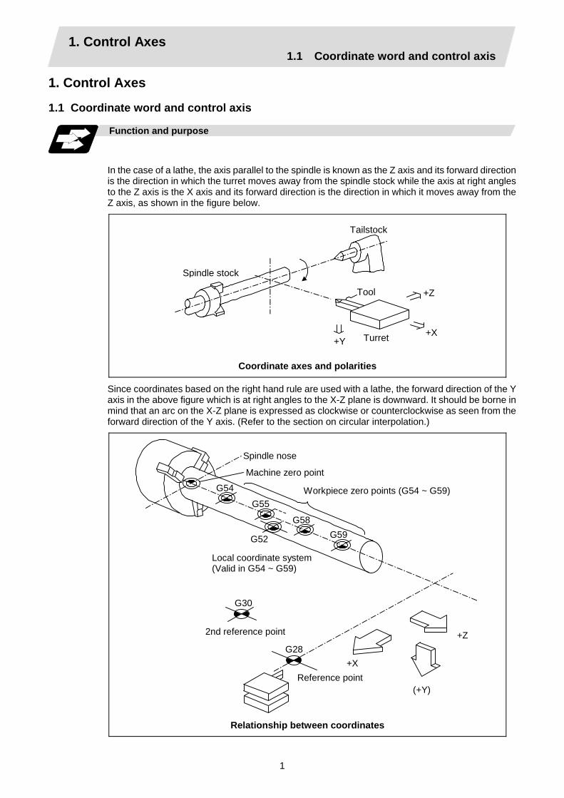
In the case of a lathe, the axis parallel to the spindle is known as the Z axis and its forward direction is the direction in which the turret moves away from the spindle stock while the axis at right angles to the Z axis is the X axis and its forward direction is the direction in which it moves away from the Z axis, as shown in the figure below.
Spindle stock
Tailstock
Tool
Turret +X +Y
+Z
Coordinate axes and polarities
Since coordinates based on the right hand rule are used with a lathe, the forward direction of the Y axis in the above figure which is at right angles to the X-Z plane is downward. It should be borne in mind that an arc on the X-Z plane is expressed as clockwise or counterclockwise as seen from the forward direction of the Y axis. (Refer to the section on circular interpolation.)
G54
G52
G58
G55
G59
G30
G28+X
(+Y)
+Z
Spindle nose
Machine zero point
Workpiece zero points (G54 ~ G59)
Local coordinate system(Valid in G54 ~ G59)
2nd reference point
Reference point
Relationship between coordinates

1. Control Axes 1.2 Coordinate systems and coordinate zero point symbols
2
1.2 Coordinate systems and coordinate zero point symbols
Function and purpose
: Reference point
: Machine coordinate zero point
: Workpiece coordinate zero points (G54 ~ G59)
Upon completion of the reference point return, the parameters are referred to and automatically set for the basic machine coordinate system and workpiece coordinate systems (G54 ~ G59). The basic machine coordinate system is set so that the first reference point is at the position designated by the parameter from the basic machine coordinate zero point (machine zero point).
X1
X3
+X
+Z
Z1
X2Z2
Hypothetical machinecoordinate system (shifted by G92)
Workpiececoordinatesystem 1 (G54)
Workpiececoordinatesystem 2 (G55)
Workpiececoordinate system 5 (G58)
Workpiece coordinate system6 (G59) Z 3
1st reference point
Machine zero pointBasic machine coordinate system
Local coordinatesystem (G52)
The local coordinate system (G52) is valid on the coordinate systems designated by the commands for the workpiece coordinate systems 1 to 6. Using the G92 command, the basic machine coordinate system can be shifted and made the hypothetical machine coordinate system. At the same time, workpiece coordinate systems 1 to 6 are also shifted.
2. Input Command Units 2.1 Input command units
3
2. Input Command Units 2.1 Input command units
Function and purpose
These are the units used for the movement amounts in the program. They are expressed in millimeters, inches or degrees (°).
2.2 Input setting units
Function and purpose
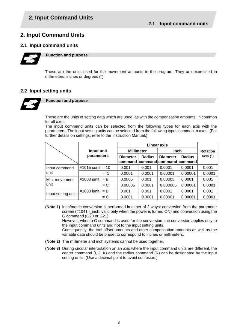
These are the units of setting data which are used, as with the compensation amounts, in common for all axes. The input command units can be selected from the following types for each axis with the parameters. The input setting units can be selected from the following types common to axes. (For further details on settings, refer to the Instruction Manual.)
Linear axis Millimeter Inch
Input unit
parameters Diameter command
Radius command
Diameter command
Radius command
Rotation axis (°)
#1015 cunit = 10 0.001 0.001 0.0001 0.0001 0.001 Input command unit = 1 0.0001 0.0001 0.00001 0.00001 0.0001
#1003 iunit = B 0.0005 0.001 0.00005 0.0001 0.001 Min. movement unit = C 0.00005 0.0001 0.000005 0.00001 0.0001
#1003 iunit = B 0.001 0.001 0.0001 0.0001 0.001 Input setting unit
= C 0.0001 0.0001 0.00001 0.00001 0.0001
(Note 1) Inch/metric conversion is performed in either of 2 ways: conversion from the parameter screen (#1041 I_inch: valid only when the power is turned ON) and conversion using the G command (G20 or G21).
However, when a G command is used for the conversion, the conversion applies only to the input command units and not to the input setting units.
Consequently, the tool offset amounts and other compensation amounts as well as the variable data should be preset to correspond to inches or millimeters.
(Note 2) The millimeter and inch systems cannot be used together.
(Note 3) During circular interpolation on an axis where the input command units are different, the center command (I, J, K) and the radius command (R) can be designated by the input setting units. (Use a decimal point to avoid confusion.)
3. Data Formats 3.1 Tape codes
4
3. Data Formats 3.1 Tape codes
Function and purpose
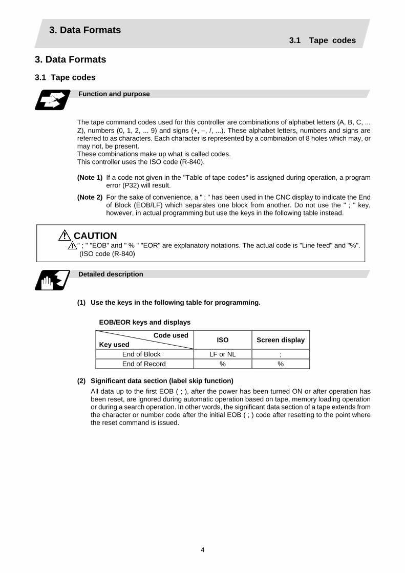
The tape command codes used for this controller are combinations of alphabet letters (A, B, C, ... Z), numbers (0, 1, 2, ... 9) and signs (+, −, /, ...). These alphabet letters, numbers and signs are referred to as characters. Each character is represented by a combination of 8 holes which may, or may not, be present. These combinations make up what is called codes. This controller uses the ISO code (R-840).
(Note 1) If a code not given in the "Table of tape codes" is assigned during operation, a program
error (P32) will result.
(Note 2) For the sake of convenience, a " ; " has been used in the CNC display to indicate the End of Block (EOB/LF) which separates one block from another. Do not use the " ; " key, however, in actual programming but use the keys in the following table instead.
CAUTION " ; " "EOB" and " % " "EOR" are explanatory notations. The actual code is "Line feed" and "%".(ISO code (R-840)
Detailed description
(1) Use the keys in the following table for programming.
EOB/EOR keys and displays
Code used Key used ISO Screen display
End of Block LF or NL ; End of Record % %
(2) Significant data section (label skip function)
All data up to the first EOB ( ; ), after the power has been turned ON or after operation has been reset, are ignored during automatic operation based on tape, memory loading operation or during a search operation. In other words, the significant data section of a tape extends from the character or number code after the initial EOB ( ; ) code after resetting to the point where the reset command is issued.

3. Data Formats 3.1 Tape codes
5
(3) Control out, control in When the ISO code is used, all data between control out "(" and control in ")" (or ";") are ignored, although these data appear on the setting and display unit. Consequently, the command tape name, number and other such data not directly related to control can be inserted in this section. This information (except (B) in the "Table of tape codes") will also be loaded, however, during tape loading. The system is set to the "control in" mode when the power is turned ON.
L C S L F RG0 0 X - 8 5 0 0 0 Y - 6 4 0 0 0 ( CUT T ERPRE T URN ) F
• • •• • • •• •• • • • • •• •• •• • • • • • •• • • •• •• •• • • ••• •••• ••• • •• • • • • • • • • • • • • • • • • • • • • • • • • • • • • • • • • • • • • • • • • • • • • • • • • •• •••• •• • ••••• ••••• ••• ••• •••••• ••••• ••• • • ••• ••••• ••• •• •••••• ••••••• • • •• • • • • •••••• •••••• •• • •• • • • • • •••••••• • • •Operator information print-out example
Information in this section is ignored and nothing is executed.
Example of ISO code
(4) EOR (%) code
Generally, the End of Record code is punched at both ends of the tape. It has the following functions: (a) Rewind stop when rewinding tape (with tape rewinder) (b) Rewind start during tape search (with tape rewinder) (c) Completion of loading during tape loading into memory
(5) Tape preparation for tape operation (with tape rewinder)
2m
10cm %
2m
10cm %; ;;;
Initial block Last block
……… ……… …………..
If a tape rewinder is not used, there is no need for the 2-meter dummy at both ends of the tape and for the head EOR (%) code.
3. Data Formats 3.1 Tape codes
6
ISO code (R-840) Feed holes
8 7 6 5 4 3 2 1 Channel No.
• • • • • 1• •• • • 2 • • • •• 3• •• • • 4 • • • • • 5 •• • •• 6• • • • ••• 7• ••• • 8 • •• • • 9 •• • 0 • • • A • • • B•• • •• C • • • D•• • • • E•• • •• F • • ••• G • • • H•• • • • I•• • • • J • • • •• K•• • • • L • • • • • M • • • •• N•• • • ••• O • • • P•• • • • Q•• • • • R • • • •• S•• • • • T • • • • • U • • • •• V•• • • ••• W•• •• • X • •• • • Y • •• • • Z • • • •• + • • • • • - • • • •• .• • • • • ,• • • • ••• /• • • • • • % • • • LF (Line Feed) or NL • • • ( (Control Out)• • • • • ) (Control In) • •• • • :• • • •• #• • • • • *• ••• • • • =•• •• • •• [•• •• • • • ] • • • ! • • • $• • • SP (Space)• • • • • CR(Carriage Return) • • • BS (Back Space) • • • HT (Horizontal Tab) • • • •• & • • ••• ’ (Apostrophe)• • •• • •• ; ••• • • <• • •• • •• > ••• • ••• ?•• • @ • • • ”••••• • ••• DEL (Delete) • NULL••••• • ••• DEL (Delete) • •
(A)
(B)
Under the ISO code, LF or NL is EOB and % is EOR. The (A) codes are stored on tape but an error results (except when they are used in the comment section) during operation. The (B) codes are non-working codes and are always ignored. (Parity V check is not executed.)
Table of tape codes

3. Data Formats 3.2 Program formats
7
3.2 Program formats
Function and purpose
The prescribed arrangement used when assigning control information to the controller is known as the program format, and the format used with this controller is called the "word address format".
Detailed description
(1) Word and address
A word is a collection of characters arranged in a specific sequence. This entity is used as the unit for processing data and for causing the machine to execute specific operations. Each word used for this controller consists of an alphabet letter and a number of several digits (sometimes with a "–" sign placed at the head of the number).
Alphabet (address)
Word
Numerals
Word configuration
*
The alphabet letter at the head of the word is the address. It defines the meaning of the numerical information which follows it. For details of the types of words and the number of significant digits of words used for this controller, refer to "Format details".
(2) Blocks
A block is a collection of words. It includes the information which is required for the machine to execute specific operations. One block unit constitutes a complete command. The end of each block is marked with an EOB (End of Block) code.
(3) Programs
A program is a collection of several blocks.
(Note 1) When there is no number following the alphabetic character in the actual program, the numeric value following the alphabetic character is handled as a 0.
(Example) G28XYZ; → G28X0Y0Z0;
3. Data Formats 3.2 Program formats
8
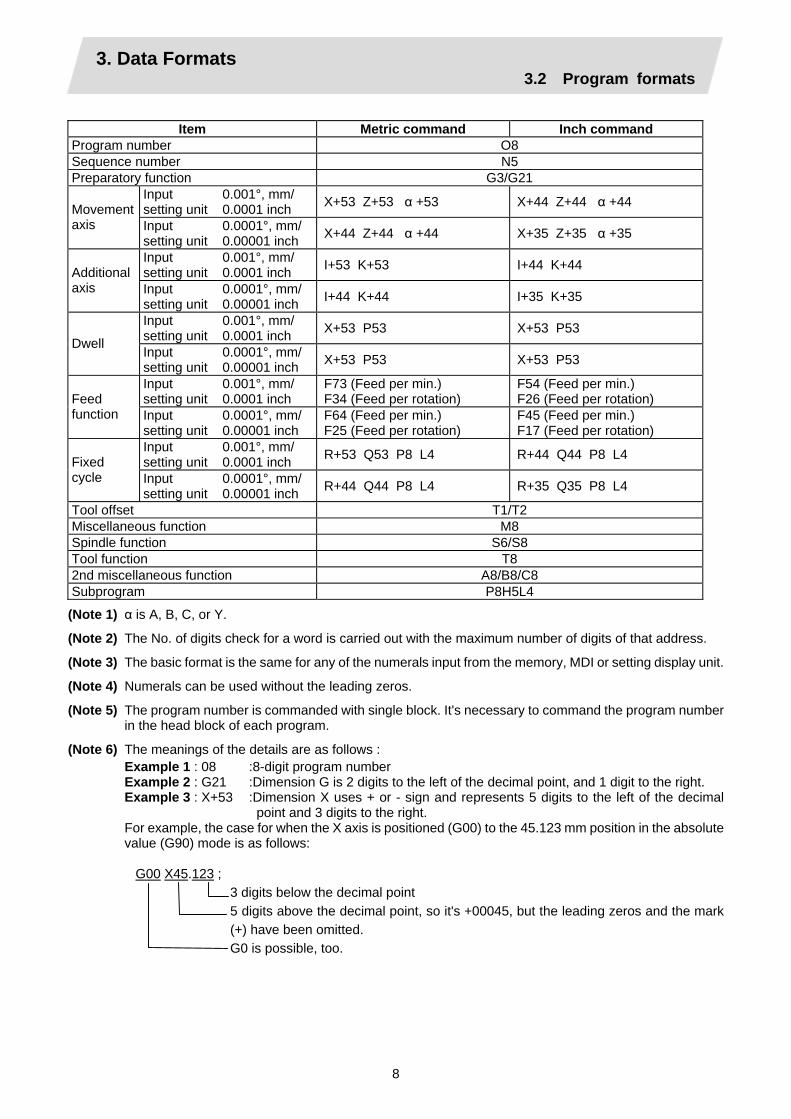
Item Metric command Inch command
Program number O8 Sequence number N5 Preparatory function G3/G21
Input setting unit
0.001°, mm/ 0.0001 inch X+53 Z+53 α +53 X+44 Z+44 α +44 Movement
axis Input setting unit
0.0001°, mm/ 0.00001 inch X+44 Z+44 α +44 X+35 Z+35 α +35
Input setting unit
0.001°, mm/ 0.0001 inch I+53 K+53 I+44 K+44 Additional
axis Input setting unit
0.0001°, mm/ 0.00001 inch I+44 K+44 I+35 K+35
Input setting unit
0.001°, mm/ 0.0001 inch X+53 P53 X+53 P53
Dwell Input setting unit
0.0001°, mm/ 0.00001 inch X+53 P53 X+53 P53
Input setting unit
0.001°, mm/ 0.0001 inch
F73 (Feed per min.) F34 (Feed per rotation)
F54 (Feed per min.) F26 (Feed per rotation) Feed
function Input setting unit
0.0001°, mm/ 0.00001 inch
F64 (Feed per min.) F25 (Feed per rotation)
F45 (Feed per min.) F17 (Feed per rotation)
Input setting unit
0.001°, mm/ 0.0001 inch R+53 Q53 P8 L4 R+44 Q44 P8 L4 Fixed
cycle Input setting unit
0.0001°, mm/ 0.00001 inch R+44 Q44 P8 L4 R+35 Q35 P8 L4
Tool offset T1/T2 Miscellaneous function M8 Spindle function S6/S8 Tool function T8 2nd miscellaneous function A8/B8/C8 Subprogram P8H5L4
(Note 1) α is A, B, C, or Y.
(Note 2) The No. of digits check for a word is carried out with the maximum number of digits of that address.
(Note 3) The basic format is the same for any of the numerals input from the memory, MDI or setting display unit.
(Note 4) Numerals can be used without the leading zeros.
(Note 5) The program number is commanded with single block. It's necessary to command the program number in the head block of each program.
(Note 6) The meanings of the details are as follows : Example 1 : 08 :8-digit program number Example 2 : G21 :Dimension G is 2 digits to the left of the decimal point, and 1 digit to the right. Example 3 : X+53 :Dimension X uses + or - sign and represents 5 digits to the left of the decimal
point and 3 digits to the right. For example, the case for when the X axis is positioned (G00) to the 45.123 mm position in the absolute value (G90) mode is as follows: G00 X45.123 ;
3 digits below the decimal point 5 digits above the decimal point, so it's +00045, but the leading zeros and the mark (+) have been omitted. G0 is possible, too.

3. Data Formats 3.3 Program address check function
9
3.3 Program address check function
Function and purpose
The program can be checked in word units when operating machining programs.
Detailed description
(1) Address check
This function enables simple checking of program addresses in word units. If the alphabetic characters are continuous, the program error (P32) will occur. Availability of this function is selected by the parameter "#1227 aux11/bit4". Note that an error will not occur for the following: • Reserved words • Comment statements
Example of program
(1) Example of program for address check (Example 1) When there are no numbers following an alphabetic character.
G28 X ; → An error will occur. Change to "G28 X0;", etc. (Example 2) When a character string is illegal.
TEST ; → An error will occur. Change to "(TEST);", etc.
3. Data Formats 3.4 Tape memory format
10
3.4 Tape memory format
Function and purpose
(1) Storage tape and significant sections (ISO, EIA automatic judgment)
Both ISO and EIA tape codes can be stored in the memory in the same way as tape operation. After resetting, ISO/EIA is automatically judged by the EOB code at the head. The interval to be stored in the memory is from the next character after the head EOB to the EOR code after resetting. The significant codes listed in the "Table of tape code" in Section 3.1 "Tape codes", in the above significant section are actually stored into the memory. All other codes are ignored and are not stored. The data between control out "(" and control in ")" are stored into the memory.
3.5 Optional block skip ; / Function and purpose
This function selectively ignores specific blocks in a machining program which starts with the "/" (slash) code.
Detailed description
(1) Provided that the optional block skip switch is ON, blocks starting with the "/" code are ignored.
They are executed if the switch is OFF. Parity check is valid regardless of whether the optional block skip switch is ON or OFF. When, for instance, all blocks are to be executed for one workpiece but specific block are not to be executed for another workpiece, the same command tape can be used to machine different parts by inserting the "/" code at the head of those specific blocks.
Precautions for using optional block skip
(1) Put the "/" code for optional block skip at the beginning of a block. If it is placed inside the block,
it is assumed as a user macro, a division instruction. (Example) N20 G1 X25. /Z25. ; .......... NG (User macro, a division instruction;
a program error results.) /N20 G1 X25. Z25. ; .......... OK (2) Parity checks (H and V) are conducted regardless of the optional block skip switch position. (3) The optional block skip is processed immediately before the pre-read buffer. Consequently, it is not possible to skip up to the block which has been read into the pre-read
buffer. (4) This function is valid even during a sequence number search. (5) All blocks with the "/" code are also input and output during tape storing and tape output,
regardless of the position of the optional block skip switch.

3. Data Formats 3.6 Program/sequence/block numbers; O, N
11
3.6 Program/sequence/block numbers; O, N
Function and purpose
These numbers are used for monitoring the execution of the machining programs and for calling both machining programs and specific stages in machining programs.
(1) Program numbers are classified by workpiece correspondence or by subprogram units, and they are designated by the address "O" followed by a number with up to 8 digits.
(2) Sequence numbers are attached where appropriate to command blocks which configure machining programs, and they are designated by the address "N" followed by a number with up to 5 digits.
(3) Block numbers are automatically provided internally. They are preset to zero every time a program number or sequence number is read, and they are counted up one at a time unless program numbers or sequence numbers are commanded in blocks which are subsequently read. Consequently, all the blocks of the machining programs given in the table below can be determined without further consideration by combinations of program numbers, sequence numbers and block numbers.
Monitor display Machining program
Program No. Sequence No. Block No. O12345678 (DEMO, PROG) ; 12345678 0 0 N100 G00 G90 X120. Z100. ; 12345678 100 0 G94 S1000 ; 12345678 100 1 N102 G71 P210 Q220 I0.2 K0.2 D0.5 F600 ; 12345678 102 0 N200 G94 S1200 F300 ; 12345678 200 0 N210 G01 X0 Z95. ; 12345678 210 0 G01 X20. ; 12345678 210 1 G03 X50. Z80. K–15. ; 12345678 210 2 G01 Z55. ; 12345678 210 3 G02 X80. Z40. I15. ; 12345678 210 4 G01 X100. ; 12345678 210 5 G01 Z30. ; 12345678 210 6 G02 Z10. K–15. ; 12345678 210 7 N220 G01 Z0 ; 12345678 220 0 N230 G00 X120. Z150. ; 12345678 230 0 N240 M02 ; 12345678 240 0 % 12345678 240 0
3. Data Formats 3.7 Parity H/V
12
3.7 Parity H/V
Function and purpose
Parity check provides a mean of checking whether the tape has been correctly perforated or not. This involves checking for perforated code errors or, in other words, for perforation errors. There are two types of parity check: Parity H and Parity V.
(1) Parity H
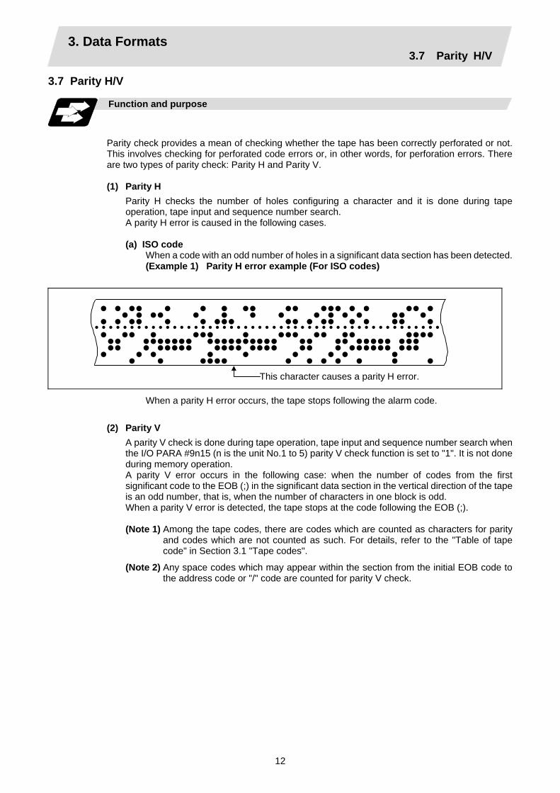
Parity H checks the number of holes configuring a character and it is done during tape operation, tape input and sequence number search. A parity H error is caused in the following cases. (a) ISO code
When a code with an odd number of holes in a significant data section has been detected. (Example 1) Parity H error example (For ISO codes)
• • •• • • • •• •• ••• • • •• • • • •• • • • • • • • • •• • • • •• • • ••• •• • •• • • •• • • • • • • • • • • • • • • • • • • • • • • • • • • • • • • • • • • • • • • • • • • • • • • • • • • • •• • ••• • ••• •• •• •••• •• ••••••• •••••••••• •• •• ••••• ••• •• • ••••• •••• •••• •• • •••••• ••• • • • • • • • • • • • •••• • • • • • • •
This character causes a parity H error.
When a parity H error occurs, the tape stops following the alarm code.
(2) Parity V A parity V check is done during tape operation, tape input and sequence number search when the I/O PARA #9n15 (n is the unit No.1 to 5) parity V check function is set to "1". It is not done during memory operation. A parity V error occurs in the following case: when the number of codes from the first significant code to the EOB (;) in the significant data section in the vertical direction of the tape is an odd number, that is, when the number of characters in one block is odd. When a parity V error is detected, the tape stops at the code following the EOB (;).
(Note 1) Among the tape codes, there are codes which are counted as characters for parity
and codes which are not counted as such. For details, refer to the "Table of tape code" in Section 3.1 "Tape codes".
(Note 2) Any space codes which may appear within the section from the initial EOB code to the address code or "/" code are counted for parity V check.
3. Data Formats 3.8 G code lists
13
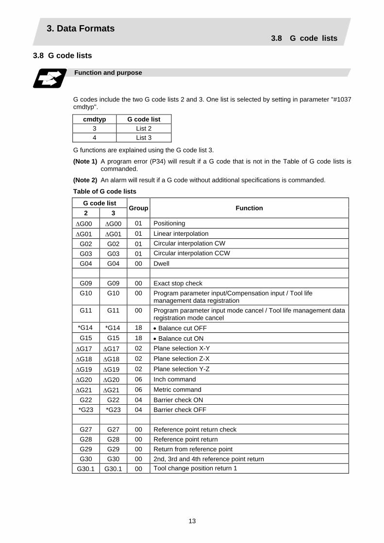
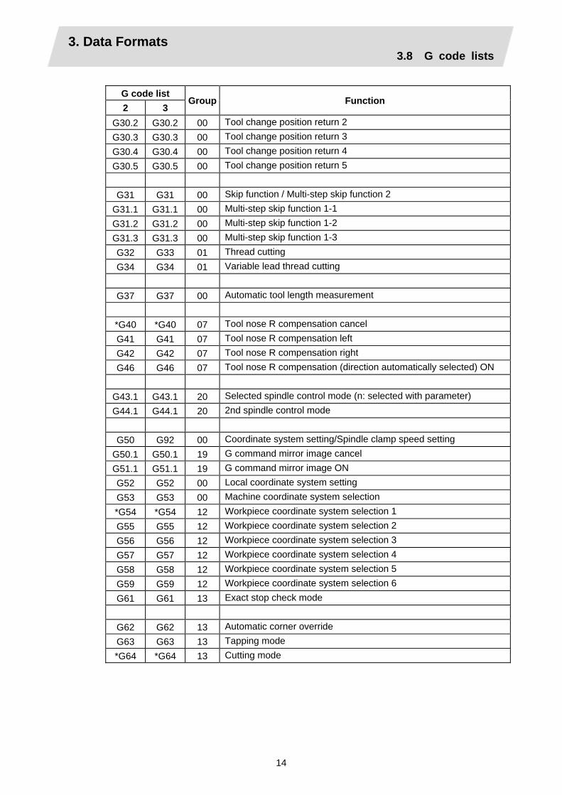
3.8 G code lists Function and purpose
G codes include the two G code lists 2 and 3. One list is selected by setting in parameter "#1037 cmdtyp".
cmdtyp G code list 3 List 2 4 List 3
G functions are explained using the G code list 3.
(Note 1) A program error (P34) will result if a G code that is not in the Table of G code lists is commanded.
(Note 2) An alarm will result if a G code without additional specifications is commanded.
Table of G code lists
G code list 2 3
Group Function
∆G00 ∆G00 01 Positioning
∆G01 ∆G01 01 Linear interpolation G02 G02 01 Circular interpolation CW G03 G03 01 Circular interpolation CCW G04 G04 00 Dwell
G09 G09 00 Exact stop check G10 G10 00 Program parameter input/Compensation input / Tool life
management data registration G11 G11 00 Program parameter input mode cancel / Tool life management data
registration mode cancel *G14 *G14 18 • Balance cut OFF G15 G15 18 • Balance cut ON
∆G17 ∆G17 02 Plane selection X-Y
∆G18 ∆G18 02 Plane selection Z-X
∆G19 ∆G19 02 Plane selection Y-Z
∆G20 ∆G20 06 Inch command
∆G21 ∆G21 06 Metric command G22 G22 04 Barrier check ON *G23 *G23 04 Barrier check OFF
G27 G27 00 Reference point return check G28 G28 00 Reference point return G29 G29 00 Return from reference point G30 G30 00 2nd, 3rd and 4th reference point return
G30.1 G30.1 00 Tool change position return 1
3. Data Formats 3.8 G code lists
14
G code list 2 3
Group Function
G30.2 G30.2 00 Tool change position return 2 G30.3 G30.3 00 Tool change position return 3 G30.4 G30.4 00 Tool change position return 4 G30.5 G30.5 00 Tool change position return 5
G31 G31 00 Skip function / Multi-step skip function 2
G31.1 G31.1 00 Multi-step skip function 1-1 G31.2 G31.2 00 Multi-step skip function 1-2 G31.3 G31.3 00 Multi-step skip function 1-3 G32 G33 01 Thread cutting G34 G34 01 Variable lead thread cutting
G37 G37 00 Automatic tool length measurement
*G40 *G40 07 Tool nose R compensation cancel G41 G41 07 Tool nose R compensation left G42 G42 07 Tool nose R compensation right G46 G46 07 Tool nose R compensation (direction automatically selected) ON
G43.1 G43.1 20 Selected spindle control mode (n: selected with parameter) G44.1 G44.1 20 2nd spindle control mode
G50 G92 00 Coordinate system setting/Spindle clamp speed setting
G50.1 G50.1 19 G command mirror image cancel G51.1 G51.1 19 G command mirror image ON G52 G52 00 Local coordinate system setting G53 G53 00 Machine coordinate system selection *G54 *G54 12 Workpiece coordinate system selection 1 G55 G55 12 Workpiece coordinate system selection 2 G56 G56 12 Workpiece coordinate system selection 3 G57 G57 12 Workpiece coordinate system selection 4 G58 G58 12 Workpiece coordinate system selection 5 G59 G59 12 Workpiece coordinate system selection 6 G61 G61 13 Exact stop check mode
G62 G62 13 Automatic corner override G63 G63 13 Tapping mode *G64 *G64 13 Cutting mode

3. Data Formats 3.8 G code lists
15
G code list 2 3
Group Function
G65 G65 00 User macro call G66 G66 14 User macro modal call A
G66.1 G66.1 14 User macro modal call B *G67 *G67 14 User macro modal call cancel G68 G68 15 Double-turret mirror image ON *G69 *G69 15 Double-turret mirror image OFF G70 G70 09 Finish cycle G71 G71 09 Longitudinal rough cutting cycle G72 G72 09 Face rough cutting cycle G73 G73 09 Formed material rough cutting cycle G74 G74 09 Face cut-off cycle G75 G75 09 Longitudinal cut-off cycle G76 G76 09 Compound type thread cutting cycle
G76.1 G76.1 09 • 2-part system simultaneous thread cutting cycle (1) G76.2 G76.2 09 • 2-part system simultaneous thread cutting cycle (2)
*G80 *G80 09 Hole drilling cycle cancel G90 G77 09 Longitudinal cutting fixed cycle G92 G78 09 Thread cutting fixed cycle G94 G79 09 Face cutting fixed cycle
G79 G83.2 09 Deep hole drilling cycle 2 G83 G83 09 Deep hole drilling cycle1 (Z axis) G84 G84 09 Tap cycle (Z axis) G85 G85 09 Boring cycle (Z axis)
G87 G87 09 Deep hole drilling cycle 1 (X axis) G88 G88 09 Tap cycle (X axis) G89 G89 09 Boring cycle (X axis)
∆G96 ∆G96 17 Constant surface speed control ON ∆G97 ∆G97 17 Constant surface speed control OFF ∆G98 ∆G94 05 Asynchronous feed (Feed per minute) ∆G99 ∆G95 05 Synchronous feed (Feed per rotation)
− ∆G90 03 Absolute value command − ∆G91 03 Incremental value command − *G98 10 Fixed cycle initial return − G99 10 Fixed cycle R point return
G113 G113 00 Spindle synchronous control OFF G114.1 G114.1 00 Spindle synchronous control ON

3. Data Formats 3.8 G code lists
16
G code list 2 3
Group Function
G115 G115 00 • Start point designation synchronizing Type 1 G116 G116 00 • Start point designation synchronizing Type 2 G117 G117 00 • Miscellaneous function output during axis movement
(Note 1) A (∗) symbol indicates the G code to be selected in each group when the power is turned
ON or when a reset is executed to initialize the modal. (Note 2) A (∆) symbol indicates the G code for which parameters selection is possible as an
initialization status when the power is turned ON or when a reset is executed to initialize the modal. Note that inch/metric changeover can only be selected when the power is turned ON.
(Note 3) A (•) symbol indicates a function dedicated for multi-part system. (Note 4) If two or more G codes from the same group are commanded, the last G code will be
valid. (Note 5) This G code list is a list of conventional G codes. Depending on the machine, movements
that differ from the conventional G commands may be included when called by the G code macro. Refer to the Instruction Manual issued by the machine manufacturer.
(Note 6) Whether the modal is initialized differs for each reset input.
(1) "Reset 1" The modal is initialized when the reset initialization parameter (#1151 rstinit) is ON.
(2) "Reset 2 "and "Reset and Rewind" The modal is initialized when the signal is input.
(3) Reset at emergency stop release Conforms to "Reset 1".
(4) When an automatic reset is carried out at the start of individual functions, such as reference point return.
Conforms to "Reset and Rewind".
CAUTION The commands with "no value after G" will be handled as "G00".

3. Data Formats 3.9 Precautions before starting machining
17
3.9 Precautions before starting machining
Precautions before machining
CAUTION When creating the machining program, select the appropriate machining conditions, and make sure that the performance, capacity and limits of the machine and NC are not exceeded. The examples do not consider the machining conditions.
Before starting actual machining, always carry out dry run operation to confirm the machining program, tool offset amount and workpiece offset amount, etc.

4. Buffer Register 4.1 Pre-read buffers
18
4. Buffer Register
Memory
MDI data
Keyboard
Mode switching
Analysis processingMax. 5 execution blocks
Pre-read buffer 5
buffer 4
Arithmetic processing
(Note) Data equivalent to 1 block are stored in 1 pre-read buffer.
buffer 3buffer 2
buffer 1
4.1 Pre-read buffers Function and purpose
During automatic processing, the contents of 1 block are normally pre-read so that program analysis processing is conducted smoothly. However, during nose R compensation, a maximum of 5 blocks are pre-read for the intersection point calculation including interference check. The specifications of the data in 1 block are as follows: (1) The data of 1 block are stored in this buffer.
(2) Only the significant codes in the significant data section are read into the pre-read buffer.
(3) When codes are sandwiched in the control in and control out, and the optional block skip function is ON, the data extending from the "/" (slash) code up to the EOB code are not read into the pre-read buffer.
(4) The pre-read buffer contents are cleared with resetting.
(5) When the single block function is ON during continuous operation, the pre-read buffer stores the following block data and then stops operation.
Precautions
(1) Depending on whether the program is executed continuously or by single blocks, the timing of
the valid/invalid for the external control signals for the optional block skip and others will differ.
(2) If the external control signal such as optional block skip is turned ON/OFF with the M command, the external control operation will not be effective on the program pre-read with the buffer register.
(3) According to the M command that operates the external controls, it prohibits pre-reading, and the recalculation is as follows:
The M command that commands the external controls is distinguished at the PLC, and the "recalculation request" for PLC → NC interface table is turned ON.
(When the "recalculation request" is ON, the program that has been pre-read is reprocessed.)

5. Position Commands 5.1 Incremental/absolute value commands
19
5. Position Commands 5.1 Incremental/absolute value commands
Function and purpose
There are 2 methods of issuing tool movement amount commands: the incremental value method and the absolute value method. The incremental value method applies for coordinates of a point which is to be moved and it issues a command using the distance from the present point; on the other hand, the absolute value system issues a command using the distance from the coordinate zero point. The following figure shows what happens when the tool is moved from point P1 to point P2.
Workpiece coordinate zero point
Spindle
X axis
Z axis
Z W P1
P2
U 2
X
Incremental and absolute value commands
Incremental value commands and absolute value commands for the X axis and Z axis are identified by address when parameter "#1076 AbsInc" is set to 1, and identified by G code (G90/ G91) when set to 0. Similarly, even with additional axes (C axis or Y axis), they are differentiated by addresses, or G code.
Command system Remarks X axis Address X Z axis Address Z
Absolute value
C/Y axis Address C/Y X axis Address U Z axis Address W
Incremental value
C/Y axis Address H/V
• Set the correspondence between addresses and axes into "#1013 axname" and "#1014 incax".
• Absolute and incremental values can be used together in the same block.
(Example) X_____ W _____ ;
Incremental value command for Z axis Absolute value command for X axis
(Note 1) When parameter "#1076 AbsInc" is 1, and H is used for the incremental command
address, address H of blocks in M98 and G10 L50 modal will be handled as the parameter of each command, and the axis will not be moved.

5. Position Commands 5.2 Radius/diameter commands
20
5.2 Radius/diameter commands
Function and purpose
The cross sections of workpieces machined on a lathe are circular, and the diameter or radius value of those circles can be used for movement commands in the X-axis direction. A radius command will move the tool by the commanded amount only, but a diameter command will move the tool both in the X-axis direction by an amount equivalent to one-half the commanded amount only and in the Z-axis direction by the commanded amount only. This system permits radius or diameter commands to be issued, depending on the parameter (#1019 dia) setting. The figure below shows the command procedure when the tool is to be moved from point P1 to point P2.
Spindle
Workpiece coordinate zero point
P1
P2
r2
r1
X axis
Z axis
X command U command Remarks Radius Diameter Radius Diameter
X = r1 X = 2r1 U = r2 U = 2r2
Even when a diameter command has been selected, only the U command can be made a radius command by parameter "#1077 radius".
Radius and diameter commands
Precautions and Restrictions
(1) In the above example, the tool moves from P1 to P2 in the minus direction of the X axis and so
when an incremental value is issued, the minus sign is given to the numerical value being commanded.
(2) In this manual, diameter commands are used in descriptions of both the X and U axes for the sake of convenience.

5. Position Commands 5.3 Inch/metric conversion
21
5.3 Inch/metric conversion; G20, G21
Function and purpose
The commands can be changed between inch and metric with the G20/G21 command.
Command format
G20/G21; G20 Inch command G21 Metric command
Detailed description
The G20 and G21 commands merely select the command units. They do not select the Input units. G20 and G21 selection is meaningful only for linear axes and it is meaningless for rotation axes.
(Example) Relationship between input command units and G20/G21 commands (with decimal
point input type I)
mm output (#1016 iout=0) inch output (#1016 iout=1)Axis Input command cunit
Command example G21 G20 G21 G20
X Z
10 10
X100 ; Z100 ;
0.100mm 0.100mm
0.254mm 0.254mm
0.0039inch 0.0039inch
0.0100inch0.0100inch
X Z
1 1
X100 ; Z100 ;
0.0100mm0.0100mm
0.0254mm0.0254mm
0.00039inch 0.00039inch
0.00100inch0.00100inch

5. Position Commands 5.4 Decimal point input
22
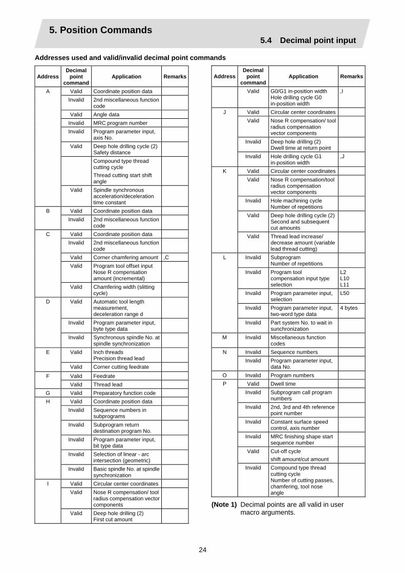
5.4 Decimal point input
Function and purpose
This function enables the decimal point to be input. It assigns the decimal point in millimeter or inch units for the machining program input information that defines the tool paths, distances and speeds. A parameter "#1078 Decpt2" selects whether minimum input command unit (type I) or zero point (type II) is to apply for the least significant digit of data without a decimal point.
Command format
. Metric system
. Inch system
Detailed description
(1) The decimal point command is valid for the distances, angles, times and speeds in machining
programs.
(2) Refer to the table rising the "Addresses used and valid/invalid decimal point commands" for details on the valid addresses for the decimal point commands.
(3) The number of significant digits in a decimal point command is shown below (for input command unit cunit=10).
Movement command (linear)
Movement command (rotation) Feedrate Dwell (X)
Integer Decimal part Integer Decimal
part Integer Decimal part Integer Decimal part
0 ~ 60000. .000 ~ .999 MM (millimeter) 0 ~ 99999. .000 ~ .999 0 ~ 99999. .000 ~ .999
0 ~ 999. .0000 ~ .9999 0 ~ 99999. .000 ~ .999
0 ~ 2362. .0000 ~ .9999 INCH (inch) 0 ~ 9999. .0000 ~ .9999 99999. (359.) .0 ~ .999
0 ~ 99. .000000 ~ .999999
0 ~ 99. .000 ~ .999
(Note) The top row gives the feedrate as a per-minute rate and the bottom row as a per-
rotation rate. (4) The decimal point command is valid even for commands defining the variable data used in
subprograms. (5) As for the minimum unit when a value is commanded without a decimal point though the
decimal point designation is valid, select the minimum input command unit determined by specifications (1µm, 10µm, etc.) or "mm". Select which to use by setting the parameter "#1078 Decpt2".
(6) Decimal point commands for decimal point invalid addresses are processed as integer data only and everything below the decimal point is ignored. Addresses which are invalid for the decimal point are D, H, L, M, N, O, P, S and T. All variable commands, however, are treated as data with decimal points.
Precautions
(1) If an arithmetic operator is inserted, the data will be handled as data with a decimal point.
(Example1) G00 X123+0 ; This is the X axis command 123mm command. It will not be 123µm.

5. Position Commands 5.4 Decimal point input
23
Example of program
(1) Example of program for decimal point valid address
Decimal point command 1 Specification division Program example When 1 = 1µm When 1 = 10µm
Decimal point command 2 When 1 = 1mm
G0 X123.45 (decimal points are all mm points)
X123.450mm X123.450mm X123.450mm
G0 X12345 X12.345mm (last digit is 1µm unit)
X123.450mm X12345.000mm
#111 = 123, #112 = 5.55 X#111 Z#112
X123.000mm, Z5.550mm
X123.000mm, Z5.550mm
X123.000mm, Z5.550mm
#113 = #111 + #112 (addition)
#113 = 128.550 #113 = 128.550 #113 = 128.550
#114 = #111 − #112 (subtraction)
#114 = 117.450 #114 = 117.450 #114 = 117.450
#115 = #111 ∗ #112 (multiplication)
#115 = 682.650 #115 = 682.650 #115 = 682.650
#116 = #111/#112 #117 = #112/#111 (division)
#116 = 22.162, #117 = 0.045
#116 = 22.162, #117 = 0.045
#116 = 22.162, #117 = 0.045
Decimal point input I, II and decimal point command validity
In the table on the next page, decimal point input I and II result in the following for commands in which a decimal point is not used in an address where a decimal point command is valid. Both decimal point input I and II become the same for commands using a decimal point.
(1) Decimal point input I
The lowest order digit of command data matches the command unit. (Example) When "X1" is commanded in 1µm system, the same result occurs as for an
"X0.001" command.
(2) Decimal point input II The lowest order digit of command data matches the command unit. (Example) When "X1" is commanded in 1µm system, the same result occurs as for an "X1."
command.
5. Position Commands 5.4 Decimal point input
24
Addresses used and valid/invalid decimal point commands
Address Decimal
point command
Application Remarks
Valid Coordinate position data Invalid 2nd miscellaneous function
code
Valid Angle data Invalid MRC program number Invalid Program parameter input,
axis No.
Valid Deep hole drilling cycle (2) Safety distance
Compound type thread cutting cycle Thread cutting start shift angle
A
Valid Spindle synchronous acceleration/deceleration time constant
Valid Coordinate position data B Invalid 2nd miscellaneous function
code
Valid Coordinate position data Invalid 2nd miscellaneous function
code
Valid Corner chamfering amount ,C Valid Program tool offset input
Nose R compensation amount (incremental)
C
Valid Chamfering width (slitting cycle)
Valid Automatic tool length measurement, deceleration range d
Invalid Program parameter input, byte type data
D
Invalid Synchronous spindle No. at spindle synchronization
Valid Inch threads Precision thread lead
E
Valid Corner cutting feedrate
Valid Feedrate F Valid Thread lead
G Valid Preparatory function code Valid Coordinate position data
Invalid Sequence numbers in subprograms
Invalid Subprogram return destination program No.
Invalid Program parameter input, bit type data
Invalid Selection of linear - arc intersection (geometric)
H
Invalid Basic spindle No. at spindle synchronization
Valid Circular center coordinates Valid Nose R compensation/ tool
radius compensation vector components
I
Valid Deep hole drilling (2) First cut amount
AddressDecimal
point command
Application Remarks
Valid G0/G1 in-position width Hole drilling cycle G0 in-position width
,I
Valid Circular center coordinates Valid Nose R compensation/ tool
radius compensation vector components
Invalid Deep hole drilling (2) Dwell time at return point
J
Invalid Hole drilling cycle G1 in-position width
,J
Valid Circular center coordinates Valid Nose R compensation/tool
radius compensation vector components
Invalid Hole machining cycle Number of repetitions
Valid Deep hole drilling cycle (2)Second and subsequent cut amounts
K
Valid Thread lead increase/ decrease amount (variable lead thread cutting)
Invalid Subprogram Number of repetitions
Invalid Program tool compensation input type selection
L2 L10 L11
Invalid Program parameter input, selection
L50
Invalid Program parameter input, two-word type data
4 bytes
L
Invalid Part system No. to wait in sunchronization
M Invalid Miscellaneous function codes
Invalid Sequence numbers N Invalid Program parameter input,
data No.
O Invalid Program numbers Valid Dwell time
Invalid Subprogram call program numbers
Invalid 2nd, 3rd and 4th reference point number
Invalid Constant surface speed control, axis number
Invalid MRC finishing shape start sequence number
Valid Cut-off cycle shift amount/cut amount
P
Invalid Compound type thread cutting cycle Number of cutting passes, chamfering, tool nose angle
(Note 1) Decimal points are all valid in user macro arguments.

5. Position Commands 5.4 Decimal point input
25
Address Decimal
point command
Application Remarks
Valid Compound type thread cutting cycle Thread height
Invalid Program tool compensation input compensation No.
Invalid Program parameter input, section No.
Valid Coordinate position data Invalid Skip signal command for
multi-step skip function 2
Valid Arc center coordinates (absolute value) (geometric)
P
Invalid Subprogram return destination sequence No.
Invalid Minimum spindle clamp rotation speed
Invalid MRC finishing shape end sequence number
Valid Cut-off cycle Cut amount/shift amount
Valid Compound type thread cutting cycle Minimum cut amount
Valid Compound type thread cutting cycle First cut amount
Valid Deep hole drilling cycle 1 Cut amount of each pass
Invalid Program tool compensation input Hypothetical tool nose point number
Invalid Deep hole drilling cycle (2) Dwell time at cut point
Valid Arc center coordinates (absolute value) (geometric)
Q
Valid Thread cutting start shift angle
Valid R-designated arc radius Valid Corner rounding circular
radius ,R
Valid Automatic tool length measurement, deceleration range r
Valid MRC longitudinal/face escape amount
Invalid MRC shaping division number
Valid Cut-off cycle, return amount Valid Cut-off cycle, escape amount Valid Compound type thread
cutting cycle, finishing allowance
Valid Compound type thread cutting cycle/turning cycle, taper difference
R
Valid Hole drilling cycle/deep hole drilling cycle (2), distance to reference point
AddressDecimal
point command
Application Remarks
Valid Program tool compensation input/nose R compensation amount
Valid Coordinate position data Valid Rough cutting cycle
(longitudinal) (face) pull amount
Valid Synchronous tap/ asynchronous tap changeover
,R
R
Valid Synchronous spindle phase shift amount
Invalid Spindle function codes Invalid Maximum spindle clamp
rotation speed
Invalid Constant surface speed control, surface speed
S
Invalid Program parameter input, word type data
2 bytes
T Invalid Tool function codes Valid Coordinate position data Valid Program tool compensation
input
Valid Rough cutting cycle (longitudinal) cutting amount
U
Valid Dwell time Valid Coordinate position data V Valid Program tool compensation
input
Valid Coordinate position data Valid Program tool compensation
input
W
Valid Rough cutting cycle (face) cutting amount
Valid Coordinate position data Valid Dwell
X
Valid Program tool compensation input
Valid Coordinate position data Y Valid Program tool compensation
input
Valid Coordinate position data Z Valid Program tool compensation
input

6. Interpolation Functions 6.1 Positioning (Rapid Traverse)
26
6. Interpolation Functions 6.1 Positioning (Rapid Traverse); G00
Function and purpose
This command is accompanied by coordinate words. It positions the tool along a linear or non-linear path from the present point as the start point to the end point which is specified by the coordinate words.
Command format
G00 Xx/Uu Zz/Ww ,Ii ; x, u, z, w Coordinate values i In-position width. A decimal point command will result in a program
error. This is valid only in the commanded block. A block that does not contain this address will follow the parameter "#1193 inpos" settings. The range is 1 to 999999 (µm).
The command addresses are valid for all additional axes.
Detailed description
(1) Once this command has been issued, the G00 mode is retained until it is changed by another
G function or until the G01, G02, G03, G33 or G34 command in the 01 group is issued. If the next command is G00, all that is required is simply that the coordinate words be specified.
(2) In the G00 mode, the tool is always accelerated at the start point of the block and decelerated at the end point. Refer to (Note4) of "Example of program".
(3) If multiple axes are controlled, the next block will be executed after confirming that the position error amounts of all the moving axes become within the specified in-position width for each part system.
(4) Any G command (G83 ~ G89) in the 09 group is cancelled (G80) by the G00 command.
(5) Whether the tool moves along a linear or non-linear path is determined by parameter, but the positioning time does not change.
(a) Linear path................. This is the same as linear interpolation (G01), and the speed is limited by the rapid traverse rate of each axis.
(b) Non-linear path .......... The tool is positioned at the rapid traverse rate independently for each axis.
(6) Refer to "Operation during in-position check" for the programmable in-position check positioning command.
CAUTION The commands with "no value after G" will be handled as "G00".

6. Interpolation Functions 6.1 Positioning (Rapid Traverse)
27
Example of program
Workpiece
Chuck
End point (+100, +150)
(Unit : mm)
+X
+Z
Start point (+180, +300)
Turret
G00 X100000 Z150000 ; Absolute value command G00 U-80000 W-150000 ; Incremental value command
(With an input setting unit of 0.001mm)
Precautions
(1) When the parameter "#1086 G0Intp" is 0, the path along which the tool is positioned is the
shortest path connecting the start and end points. The positioning speed is automatically calculated so that the shortest distribution time is obtained in order that the commanded speeds for each axis do not exceed the rapid traverse rate. When, for instance, the X-axis and Z-axis rapid traverse rates are both 9600mm/min, the tool will follow the path in the figure below if the following is programmed:
G00 Z–300000 X400000 ; (With an input setting unit of 0.001mm)
End point
(Unit : mm)
Start point
fz
fx
X
Z
300
400
Actual X axis rate: 6400 mm/min
Actual Z axis rate: 9600 mm/min

6. Interpolation Functions 6.1 Positioning (Rapid Traverse)
28
(2) When parameter "#1086 G0Intp" is 1, the tool will move along the path from the start point to the end point at the rapid traverse rate of each axis.
When, for instance, the X-axis and Z-axis rapid traverse rates are both 9600 mm/min, the tool will follow the path in the figure below if the following is programmed:
G00 Z − 300000 X400000 ; (With an input setting unit of 0.001mm)
fz
fx
X
Z
300 40
0
End point
Start point
(Unit : mm)
Actual X axis rate: 9600 mm/min
Actual Z axis rate: 9600 mm/min
(3) The rapid traverse rate for each axis with the G00 command differs according to the individual machine and so reference should be made to the machine specifications manual.
(4) Rapid traverse (G00) deceleration check There are two methods for the deceleration check at rapid traverse; commanded deceleration
method and in-position check method. Select a method with the parameter "#1193 inpos".
When "inpos" = "1" Upon completion of the rapid traverse (G00), the next block will be executed after confirming that the remaining distances for each axis are below the fixed amounts. (Refer to the following drawing.) The confirmation of the remaining distance should be done with the imposition width, LR. LR is the setting value for the servo parameter "#2224 SV024". The purpose of checking the rapid traverse deceleration is to minimize the time it takes for positioning. The bigger the setting value for the servo parameter "#2224 SV024", the longer the reduced time is, but the remaining distance of the previous block at the starting time of the next block also becomes larger, and this could become an obstacle in the actual processing work. The check for the remaining distance is done at set intervals. Accordingly, it may not be possible to get the actual amount of time reduction for positioning with the setting value SV024.

6. Interpolation Functions 6.1 Positioning (Rapid Traverse)
29
When "inpos" = "0"
Upon completion of the rapid traverse (G00), the next block will be executed after the deceleration check time (Td) has elapsed. The deceleration check time (Td) is as follows, depending on the acceleration/deceleration type. (a) Linear acceleration/linear deceleration Td = Ts + α
Ts
Td
Previous block Next block
Ts : Acceleration/deceleration time constant Td : Deceleration check time Td = Ts + ( 0 ~ 14ms)
(b) Exponential acceleration/linear deceleration Td = 2 × Ts + α
2 × Ts
Td Ts
Previous block Next block
Ts : Acceleration/deceleration time constant
Td : Deceleration check time Td = 2 × Ts + ( 0 ~ 14ms)
(c) Exponential acceleration/exponential deceleration Td = 2 × Ts + α
Ts
Td
Previous block Next block
Ts : Acceleration/deceleration time constant
Td : Deceleration check time Td = 2 × Ts + ( 0 ~ 14ms)
Where Ts is the acceleration time constant, α = 0 to 14ms The time required for the deceleration check during rapid traverse is the longest among the rapid traverse deceleration check times of each axis determined by the rapid traverse acceleration/deceleration time constants and by the rapid traverse acceleration/deceleration mode of the axes commanded simultaneously.
6. Interpolation Functions 6.1 Positioning (Rapid Traverse)
30
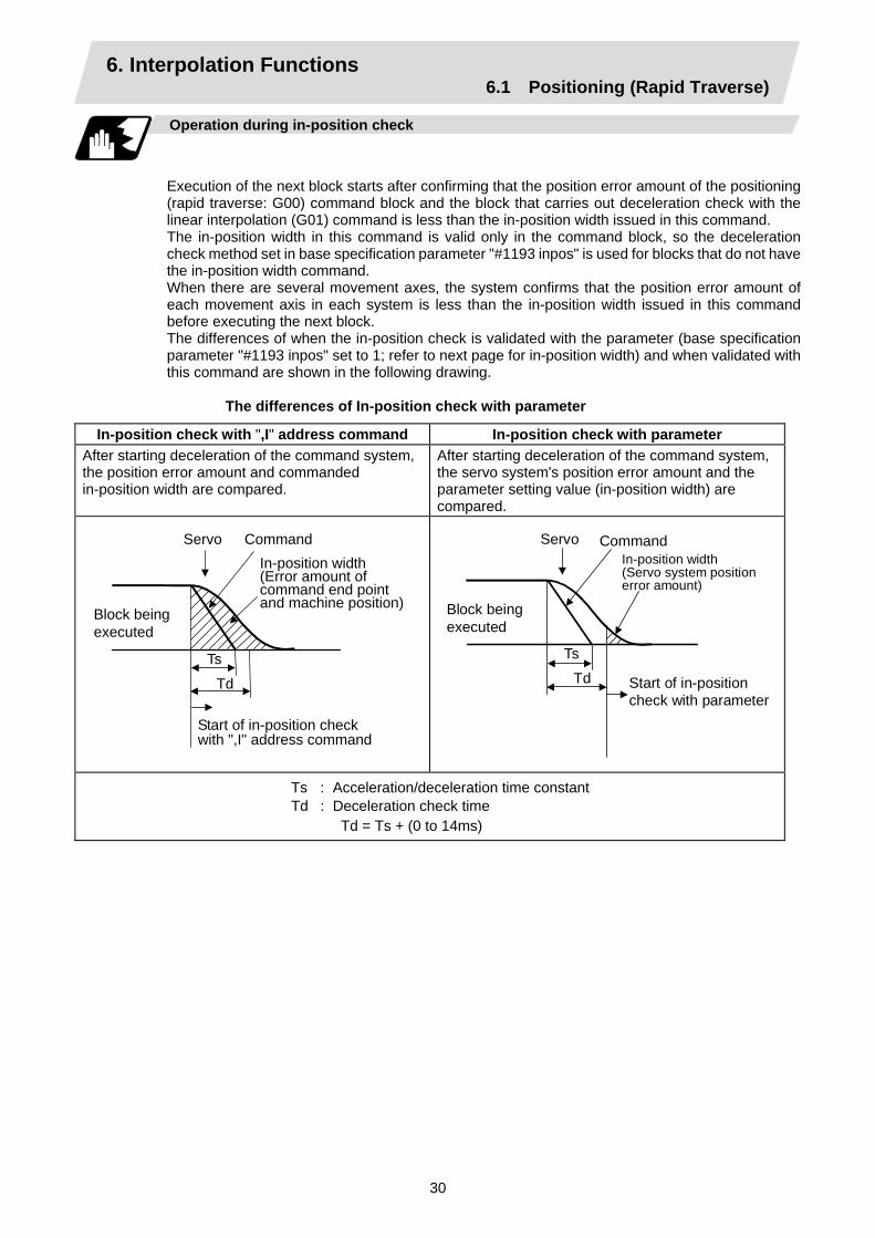
Operation during in-position check
Execution of the next block starts after confirming that the position error amount of the positioning (rapid traverse: G00) command block and the block that carries out deceleration check with the linear interpolation (G01) command is less than the in-position width issued in this command. The in-position width in this command is valid only in the command block, so the deceleration check method set in base specification parameter "#1193 inpos" is used for blocks that do not have the in-position width command. When there are several movement axes, the system confirms that the position error amount of each movement axis in each system is less than the in-position width issued in this command before executing the next block. The differences of when the in-position check is validated with the parameter (base specification parameter "#1193 inpos" set to 1; refer to next page for in-position width) and when validated with this command are shown in the following drawing.
The differences of In-position check with parameter
In-position check with ",I" address command In-position check with parameter After starting deceleration of the command system, the position error amount and commanded in-position width are compared.
After starting deceleration of the command system, the servo system's position error amount and the parameter setting value (in-position width) are compared.
Servo Command In-position width(Error amount of command end point and machine position)
Start of in-position check with ",I" address command
Block being executed
Ts
Td
Servo Command In-position width (Servo system positionerror amount)
Start of in-position check with parameter
Block being executed
TsTd
Ts : Acceleration/deceleration time constant Td : Deceleration check time Td = Ts + (0 to 14ms)
6. Interpolation Functions 6.1 Positioning (Rapid Traverse)
31
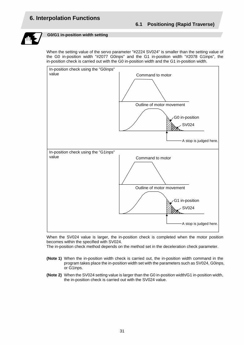
G0/G1 in-position width setting
When the setting value of the servo parameter "#2224 SV024" is smaller than the setting value of the G0 in-position width "#2077 G0inps" and the G1 in-position width "#2078 G1inps", the in-position check is carried out with the G0 in-position width and the G1 in-position width.
In-position check using the "G0inps" value
Command to motor
Outline of motor movement
G0 in-position
SV024
A stop is judged here.
In-position check using the "G1inps" value
Command to motor
Outline of motor movement
G1 in-position
SV024
A stop is judged here.
When the SV024 value is larger, the in-position check is completed when the motor position becomes within the specified with SV024. The in-position check method depends on the method set in the deceleration check parameter.
(Note 1) When the in-position width check is carried out, the in-position width command in the program takes place the in-position width set with the parameters such as SV024, G0inps, or G1inps.
(Note 2) When the SV024 setting value is larger than the G0 in-position width/G1 in-position width, the in-position check is carried out with the SV024 value.
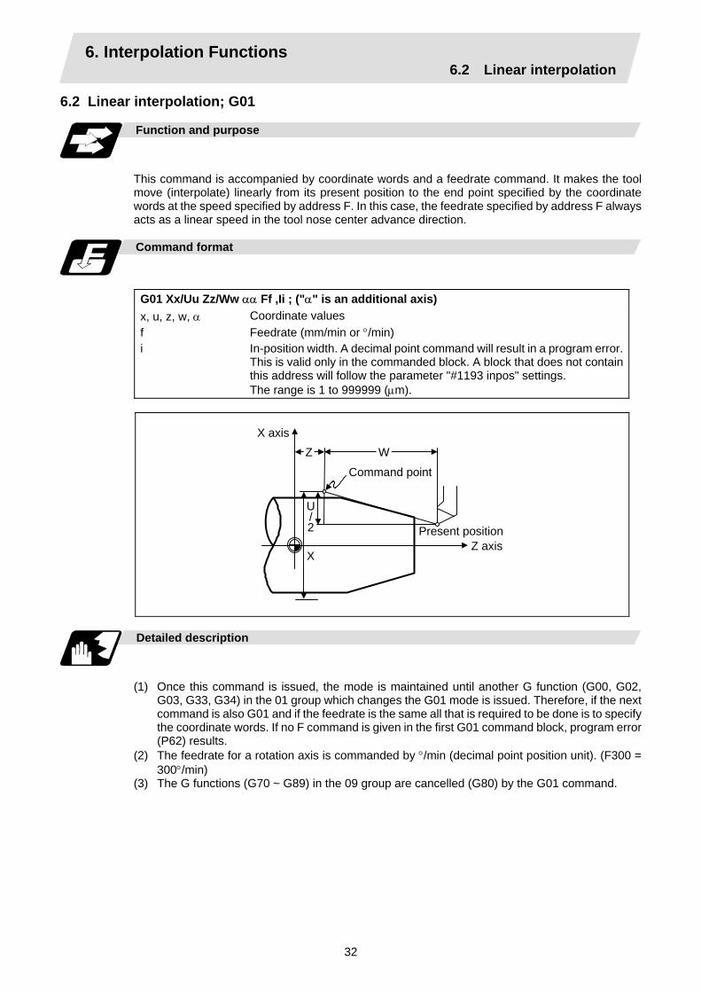
6. Interpolation Functions 6.2 Linear interpolation
32
6.2 Linear interpolation; G01
Function and purpose
This command is accompanied by coordinate words and a feedrate command. It makes the tool move (interpolate) linearly from its present position to the end point specified by the coordinate words at the speed specified by address F. In this case, the feedrate specified by address F always acts as a linear speed in the tool nose center advance direction.
Command format
G01 Xx/Uu Zz/Ww αα Ff ,Ii ; ("α" is an additional axis) x, u, z, w, α f i
Coordinate values Feedrate (mm/min or °/min) In-position width. A decimal point command will result in a program error. This is valid only in the commanded block. A block that does not contain this address will follow the parameter "#1193 inpos" settings. The range is 1 to 999999 (µm).
X axis
Z axis X
Present position
U/2
Z W
Command point
Detailed description
(1) Once this command is issued, the mode is maintained until another G function (G00, G02,
G03, G33, G34) in the 01 group which changes the G01 mode is issued. Therefore, if the next command is also G01 and if the feedrate is the same all that is required to be done is to specify the coordinate words. If no F command is given in the first G01 command block, program error (P62) results.
(2) The feedrate for a rotation axis is commanded by °/min (decimal point position unit). (F300 = 300°/min)
(3) The G functions (G70 ~ G89) in the 09 group are cancelled (G80) by the G01 command.
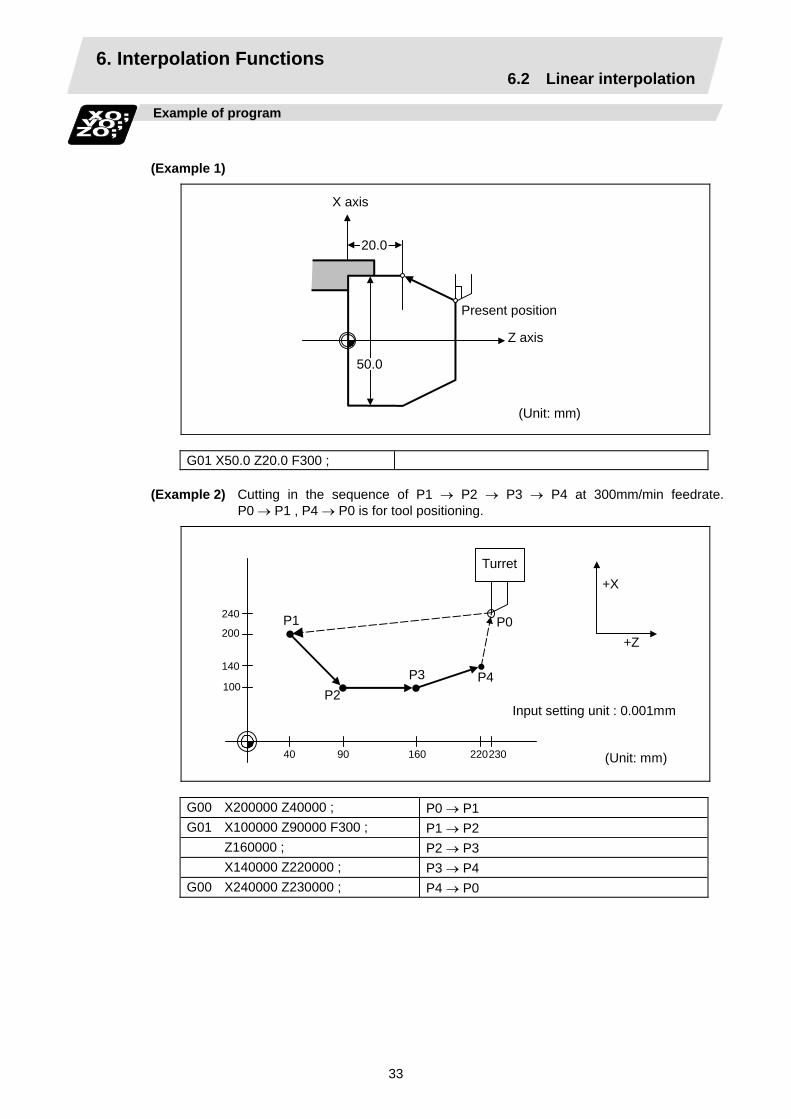
6. Interpolation Functions 6.2 Linear interpolation
33
Example of program
(Example 1)
20.0
50.0
Z axis
Present position
X axis
(Unit: mm)
G01 X50.0 Z20.0 F300 ;
(Example 2) Cutting in the sequence of P1 → P2 → P3 → P4 at 300mm/min feedrate. P0 → P1 , P4 → P0 is for tool positioning.
Turret
240
200
140
100
2209040 230160
P1
P2P3 P4
P0
+X
+Z
Input setting unit : 0.001mm
(Unit: mm)
G00 X200000 Z40000 ; P0 → P1 G01 X100000 Z90000 F300 ; P1 → P2 Z160000 ; P2 → P3 X140000 Z220000 ; P3 → P4 G00 X240000 Z230000 ; P4 → P0
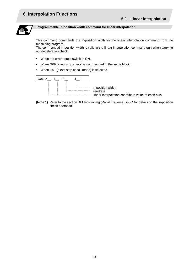
6. Interpolation Functions 6.2 Linear interpolation
34
Programmable in-position width command for linear interpolation
This command commands the in-position width for the linear interpolation command from the machining program. The commanded in-position width is valid in the linear interpolation command only when carrying out deceleration check.
• When the error detect switch is ON.
• When G09 (exact stop check) is commanded in the same block.
• When G61 (exact stop check mode) is selected. G01 X__ Z__ F__ ,I__ ;
In-position width Feedrate Linear interpolation coordinate value of each axis
(Note 1) Refer to the section "6.1 Positioning (Rapid Traverse); G00" for details on the in-position check operation.

6. Interpolation Functions 6.3 Circular Interpolation
35
6.3 Circular Interpolation; G02, G03 Function and purpose
These commands serve to move the tool along a circular.
Command format
G02 (G03) Xx/Uu Zz/Ww Ii Kk Ff ; G02 Clockwise (CW) (G03) Counterclockwise (CCW) Xx/Uu Circular end point coordinates, X axis (absolute value of workpiece
coordinate system for X, incremental value from present position for U) Zz/Ww Circular end point coordinates, Z axis (absolute value of workpiece
coordinate system for Z, incremental value from present position for W) Ii Circular center, X axis (for I, incremental value of X coordinate at center as
seen from start point. Command as "radius command".) Kk Circular center, Z axis (for K, incremental value of Z coordinate at center as
seen from start point) Ff Feedrate
X
Z KW
U/2
I
End point
Start point
Z axis
CenterX axis

6. Interpolation Functions 6.3 Circular Interpolation
36
Detailed description
(1) G02 (or G03) is retained until another G command (G00, G01, G33, or G34) in the 01 group
that changes its mode is issued. The direction of the circular rotation is differentiated by G02 and G03: G02 : Clockwise (CW) G03 : Counterclockwise (CCW)
Turret
Turret +X
+X
+X
+X
+Z
+Z
+Z
CCW(G03)
CCW(G03)
CW(G02)
CW(G02)
Chuck
Work- piece
(2) An arc which extends for more than one quadrant can be executed with a single block command.
(3) The following information is needed for circular interpolation.
(a) Rotation direction :Clockwise (G02) or counterclockwise (G03)
(b) Circular end point coordinates :Given by addresses X, Z, U, W
(c) Circular center coordinates :Given by addresses I, K (incremental value commands)
(d) Feedrate :Given by address F
(4) A program error results when I, K or R is not commanded. Consideration must be given to the sign for I and K since I is the distance in the X-axis direction to the arc center as seen from the start point and K is the distance in the Z-axis direction.
(5) No T commands can be issued in the G2/G3 modal status. A program error (P151) results if a T command is issued in the G2/G3 modal status.
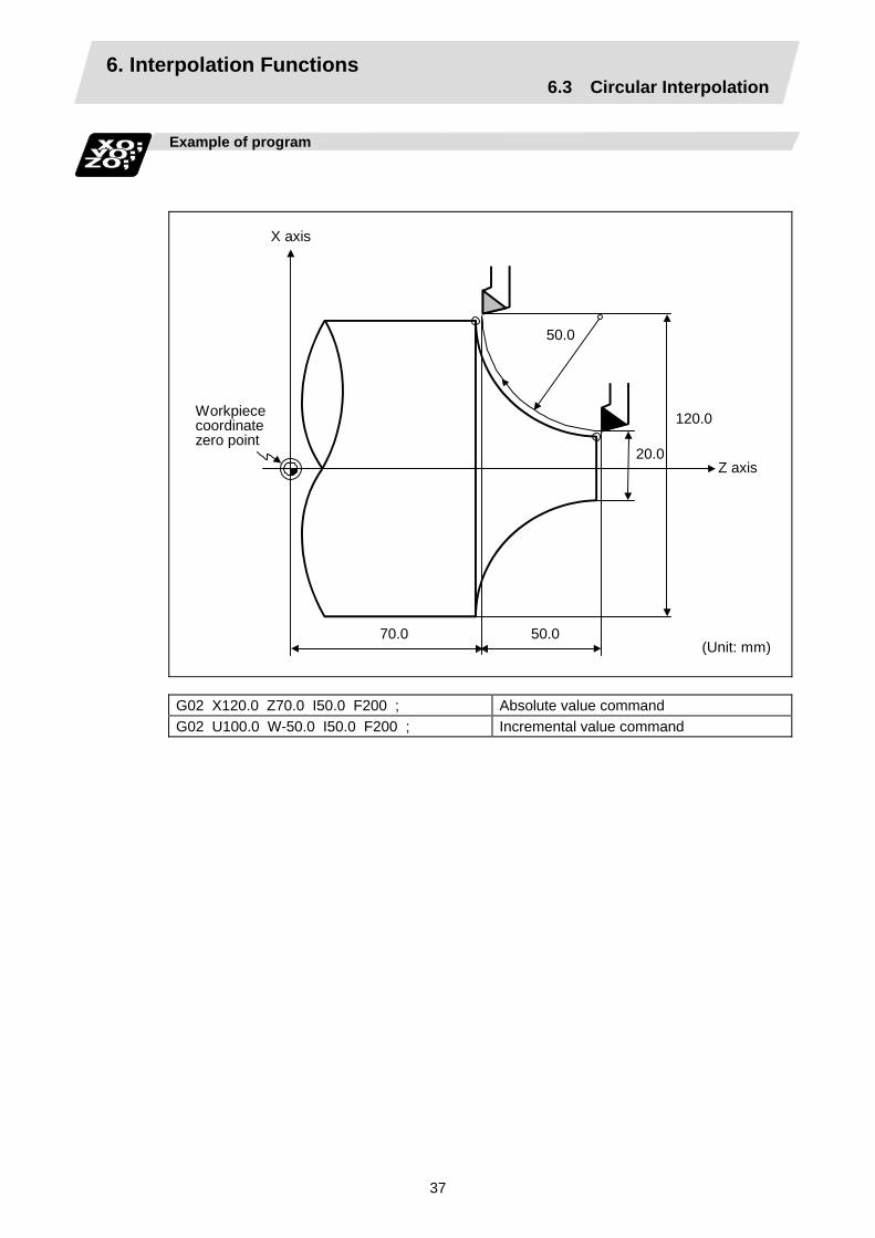
6. Interpolation Functions 6.3 Circular Interpolation
37
Example of program
120.0
20.0
70.0 50.0
50.0
(Unit: mm)
Z axis
X axis
Workpiece coordinatezero point
G02 X120.0 Z70.0 I50.0 F200 ; Absolute value command G02 U100.0 W-50.0 I50.0 F200 ; Incremental value command
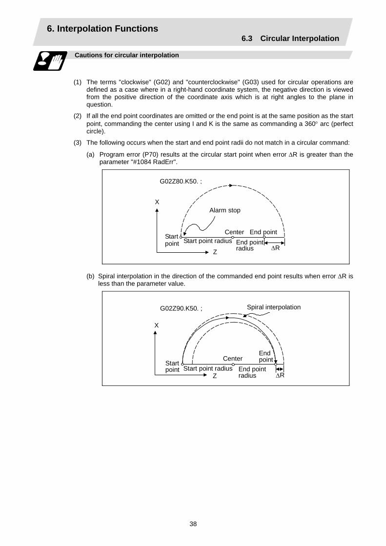
6. Interpolation Functions 6.3 Circular Interpolation
38
Cautions for circular interpolation
(1) The terms "clockwise" (G02) and "counterclockwise" (G03) used for circular operations are
defined as a case where in a right-hand coordinate system, the negative direction is viewed from the positive direction of the coordinate axis which is at right angles to the plane in question.
(2) If all the end point coordinates are omitted or the end point is at the same position as the start point, commanding the center using I and K is the same as commanding a 360° arc (perfect circle).
(3) The following occurs when the start and end point radii do not match in a circular command:
(a) Program error (P70) results at the circular start point when error ∆R is greater than the parameter "#1084 RadErr".
G02Z80.K50. ;
∆R
X
Z
Alarm stop
Start point radius End point radius
Center End point Start point
(b) Spiral interpolation in the direction of the commanded end point results when error ∆R is less than the parameter value.
Spiral interpolation
∆R
G02Z90.K50. ;
X
ZStart point radius End point
radius
CenterStart point
Endpoint

6. Interpolation Functions 6.4 R specification circular interpolation
39
6.4 R specification circular interpolation; G02, G03
Function and purpose
Along with the conventional circular interpolation commands based on the circular center coordinate (I, K) designation, these commands can also be issued by directly designating the circular radius R.
Command format
G02 (G03) Xx/Uu Zz/Ww Rr Ff; G02 (G03) x/u z/w r f
Clockwise (CW) Counterclockwise (CCW) Circular end point coordinate, X axis Circular end point coordinate, Z axis Circular radius Feedrate
Detailed description
The circular center is on the bisector line which is perpendicular to the line connecting the start and end paints of the circular. The point, where the circular with the specified radius whose start point is the center intersects the perpendicular bisector line, serves as the center coordinates of the circular command. If the R sign of the commanded program is plus, the circular is smaller than a semicircular; if it is minus, the circular is larger than a semicircular.
O1
O2
L
r
Circular path when R sign is minus
End point
Circular path when R sign is plus
Center point
Center point
Start point
The following condition must be met with an R specification circular interpolation command: ≤ 1
When L/2 - r > (parameter : #1084 RadErr), an alarm will occur.
Where L is the line from the start point to end point. If an R specification and I, K specification are given at the same time in the same block, the circular command with the R specification takes precedence. In the case of a full-circle command (where the start and end points coincide), an R specification circular command will be completed immediately even if it is issued and no operation will be executed. An I, K specification circular command should therefore be used in such a case.
L 2 × r

6. Interpolation Functions 6.4 R specification circular interpolation
40
Example of program
(Example 1)
G03 Zz1 Xx1 Rr1 Ff1 ; R specification circular on Z-X plane
(Example 2)
G02 Xx1 Zz1 Ii1 Kk1 Rr1 Ff1 ; R specification circular on X-Z plane (When the R specification and I, K specification are contained in the same block, the R specification has priority in processing.)
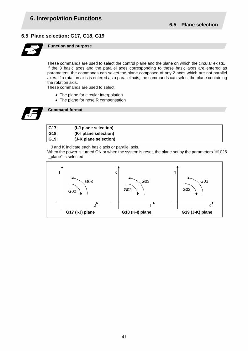
6. Interpolation Functions 6.5 Plane selection
41
6.5 Plane selection; G17, G18, G19
Function and purpose
These commands are used to select the control plane and the plane on which the circular exists. If the 3 basic axes and the parallel axes corresponding to these basic axes are entered as parameters, the commands can select the plane composed of any 2 axes which are not parallel axes. If a rotation axis is entered as a parallel axis, the commands can select the plane containing the rotation axis. These commands are used to select:
• The plane for circular interpolation • The plane for nose R compensation
Command format
G17; G18; G19;
(I-J plane selection) (K-I plane selection) (J-K plane selection)
I, J and K indicate each basic axis or parallel axis. When the power is turned ON or when the system is reset, the plane set by the parameters "#1025 I_plane" is selected.
I
J
G02
G03
I
K
G02
G03
K
J
G02
G03
G17 (I-J) plane G18 (K-I) plane G19 (J-K) plane

6. Interpolation Functions 6.5 Plane selection
42
Parameter entry
#1026 to 1028
base_I, J, K #1029 to 1031
aux_I, J, K I X Y J Y K Z
Plane selection system
This section describes the plane selection for the parameter entry samples shown in Fig. 1.
(1) Axis addresses assigned in the same block as the plane selection (G17, G18, G19) command
determine which of the basic axes or parallel axes are to be in the actual plane selected.
(Example)
G17XY; Y
X
G02
G03
G18XZ; X
Z
G02
G03
G19YZ; Z
Y
G02
G03
(2) Plane selection is not performed with blocks in which the plane selection G code (G17, G18, G19) is not assigned.
G18 X_ Z_ ; Z-X plane Y_ Z_ ; Z-X plane (no plane change)
(3) When the axis addresses are omitted in the block containing the plane selection G codes (G17, G18, G19), it is assumed that the axis addresses of the 3 basic axes have been assigned.
G18 ; (Z-X plane = G18 XZ ;)
(4) When the basic axes or their parallel axes are duplicated and assigned in the same block as the plane selection G code (G17, G18, G19), the plane is determined in the order of basic axes, and then parallel axes.
G18 XYZ ; The Z-X plane is selected. Therefore, the Y movement is unrelated to the selected plane.
(Note 1) When the "2" in the parameter "#1025 I_plane" is kept ON, the G18 plane is selected
when the power is turned ON or when the system is reset.
Basic axes and parallel axes can be entered in the parameters. The same axis name can be entered in duplication, but when it is assigned in duplication, the plane is determined as "Plane selection system (4) ". It is not possible to set axes which have not beenentered as control axes. Fig. 1 Examples of plane selection
parameter entry

6. Interpolation Functions 6.6 Thread cutting
43
6.6 Thread cutting 6.6.1 Constant lead thread cutting; G33
Function and purpose
The G33 command exercises feed control over the tool which is synchronized with the spindle rotation and so this makes it possible to conduct constant-lead straight thread-cutting, tapered thread-cutting, and continuous thread-cutting.
Straight thread Scrolled thread Continuous thread
F/E
F/E
F/E
Command format
G33 Zz/Ww Xx/Uu Ff Qq ; (Normal lead thread cutting commands) Zz, Ww, Xx, Uu Ff Qq
Thread end point coordinates Lead of long axis (axis which moves most) direction Thread cutting start shift angle, 0.001 to 360.000°
G33 Zz/Ww Xx/Uu Ee Qq ; (Precision lead thread cutting commands) Zz, Ww, Xx, Uu Ee Qq
Thread end point coordinates Lead of long axis (axis which moves most) direction Thread cutting start shift angle, 0.001 to 360.000°
W
X
Z
U/2 α
δ1 δ2
X axis
Start point
End point
Z axis

6. Interpolation Functions 6.6 Thread cutting
44
Detailed description
(1) The E command is also used for the number of ridges in inch thread cutting, and whether the
ridge number or precision lead is to be designated can be selected by parameter setting. (Set the parameter "#1229 set 01/bit" to "1" for precision lead designation.)
(2) The lead in the long axis direction is commanded for the taper thread lead.
U/2
X
W
Z
a°
When a < 45°, the lead is in Z-axis direction. When a > 45°, the lead is in X-axis direction. When a = 45°, the lead can be in either Z or X-axis direction.
Tapered thread section
Thread cutting metric input
Input unit system B (0.001mm) C (0.0001mm)
Command address F (mm/rev) E (mm/rev) E (ridges/inch) F (mm/rev) E (mm/rev) E (ridges/inch)
Minimum command
unit
1 (= 0.0001), (1.=1.0000)
1 (= 0.00001),(1.=1.00000)
1 (= 1.00), (1.=1.00)
1 (= 0.00001),(1.=1.00000)
1(=0.000001), (1.=1.000000)
1 (= 1.000), (1.=1.000)
Command range
0.0001 ~ 999.9999
0.00001 ~ 999.99999
0.03 ~ 999.99
0.00001 ~ 99.99999
0.000001 ~ 99.999999
0.255 ~9999.999
Thread cutting inch input
Input unit system B (0.0001inch) C (0.00001inch)
Command address F (inch/rev) E (inch/rev) E (ridges/inch) F (inch/rev) E (inch/rev) E (ridges/inch)
Minimum command
unit
1(=0.000001), (1.=1.000000)
1(=0.0000001),(1.=1.0000000)
1 (= 1), (1.=1.0000)
1(=0.0000001),(1.=1.0000000)
1(=0.00000001), (1.=1.00000000)
1(=1), (1.=1.00000)
Command range
0.000001 ~ 99.999999
0.000010 ~ 9.9999999
0.0101 ~ 9999.9999
0.0000001 ~ 9.9999999
0.00000001 ~ 0.99999999
0.10001 ~999.99999
(Note 1) It is not possible to assign a lead where the feedrate as converted into per-minute feed exceeds the maximum cutting feedrate.
(3) The constant surface speed control function should not be used for taper thread cutting commands or scrolled thread cutting commands.
(4) The spindle rotation speed should be kept constant throughout from the rough cutting until the finishing.
(5) If the feed hold function is employed during thread cutting to stop the feed, the thread ridges will lose their shape. For this reason, feed hold does not function during thread cutting. Note that this is valid from the time the thread cutting command is executed to the time the axis moves. If the feed hold switch is pressed during thread cutting, block stop will result at the end point of the block following the block in which thread cutting is completed (no longer G33 mode).

6. Interpolation Functions 6.6 Thread cutting
45
(6) The converted cutting feedrate is compared with the cutting feed clamp rate when thread cutting starts, and if it is found to exceed the clamp rate, an operation error will result.
(7) In order to protect the lead during thread cutting, a cutting feedrate which has been converted may sometimes exceed the cutting feed clamp rate.
(8) An illegal lead is normally produced at the start of the thread and at the end of the cutting because of servo system delay and other such factors. Therefore, it is necessary to command a thread length which is determined by adding the illegal lead lengths δ1 and δ2 to the required thread length.
(9) The spindle rotation speed is subject to the following restriction:
1 ≤ R ≤ Maximum feedrate
Thread lead Where R ≤ Tolerable speed of encoder (r/min) R = Spindle rotation speed (r/min) Thread lead = mm or inches Maximum feedrate = mm/min or inch/mm (this is subject to the restrictions imposed by the machine specifications).
(10) Dry run is valid for thread cutting but the feedrate based on dry run is not synchronized with the spindle rotation.
The dry run signal is checked at the start of thread cutting and any switching during thread cutting is ignored.
(11) Synchronous feed applies for the thread cutting commands even with an asynchronous feed command (G94).
(12) Spindle override is invalid and 100% fixed during thread cutting.
(13) When a thread cutting command is programmed during nose R compensation, the compensation is temporarily canceled and the thread cutting is executed.
(14) When the mode is switched to another automatic mode while G33 is executed, the following block which does not contain a thread cutting command is first executed and then the automatic operation stops.
(15) When the mode is switched to the manual mode while G33 is executed, the following block which does not contain a thread cutting command is first executed and then the automatic operation stops. In the case of a single block, the following block which does not contain a thread cutting command (When G33 mode is cancelled) is first executed and then the automatic operation stops. Note that automatic operation is stopped until the G33 command axis starts moving.
(16) The thread cutting command waits for the single rotation sync signal of the rotary encoder and starts movement. Note that when using multiple part systems, if one part system issues a thread cutting command during ongoing thread cutting by another part system, the movement will start without waiting for the rotary encoder single rotation sync signal. Therefore, carry out synchronizing between part systems before issuing a thread cutting command with multiple part systems.
(17) The thread cutting start shift angle is not a modal. If there is no Q command with G33, this will be handled as "Q0".
(18) If a value exceeding 360.000 is commanded with G33 Q, this will be handled as "Q360.000".
(19) G33 cuts one row with one cycle. To cut two rows, change the Q value, and issue the same command.
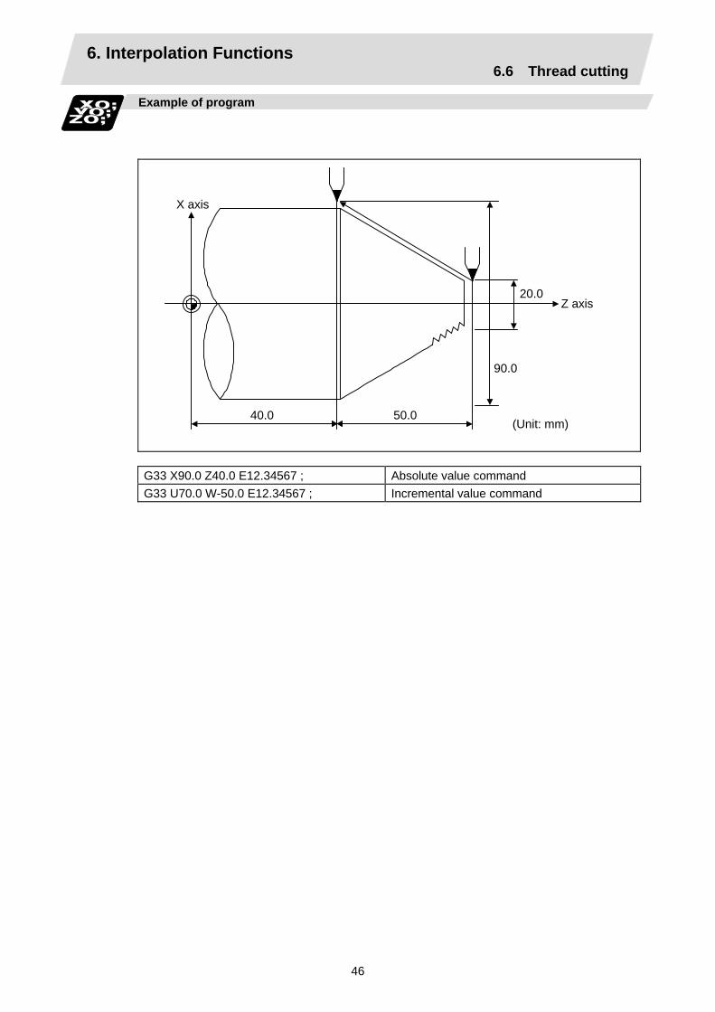
6. Interpolation Functions 6.6 Thread cutting
46
Example of program
40.0 50.0
90.0
20.0 Z axis
X axis
(Unit: mm)
G33 X90.0 Z40.0 E12.34567 ; Absolute value command G33 U70.0 W-50.0 E12.34567 ; Incremental value command

6. Interpolation Functions 6.6 Thread cutting
47
6.6.2 Inch thread cutting; G33
Function and purpose
If the number of ridges per inch in the long axis direction is assigned in the G33 command, the feed of the tool synchronized with the spindle rotation will be controlled, which means that constant-lead straight thread-cutting, tapered thread-cutting, and continuous thread-cutting can be performed.
Command format
G33 Zz/Ww Xx/Uu Ee Qq; Zz,Ww,Xx,Uu Ee Qq
Thread end point addresses and coordinates Number of ridges per inch in direction of long axis (axis which moves most) (decimal point command can also be assigned) Thread cutting start shift angle, 0.001 to 360.000°
W
Z
U/2 α
δ1 δ2
X
X axis
Z axis
End point
Start point
Detailed description
(1) The number of ridges in the long axis direction is assigned as the number of ridges per inch.
(2) The E code is also used to assign the precision lead length, and whether the ridge number or precision lead length is to be designated can be selected by parameter setting. (The number of ridges is designated by setting parameter "#1229 set 01/bit 1" to "0".)
(3) The E command value should be set within the lead value range when the lead is converted.
(4) See Section "6.6.1 Constant lead thread cutting" for other details.
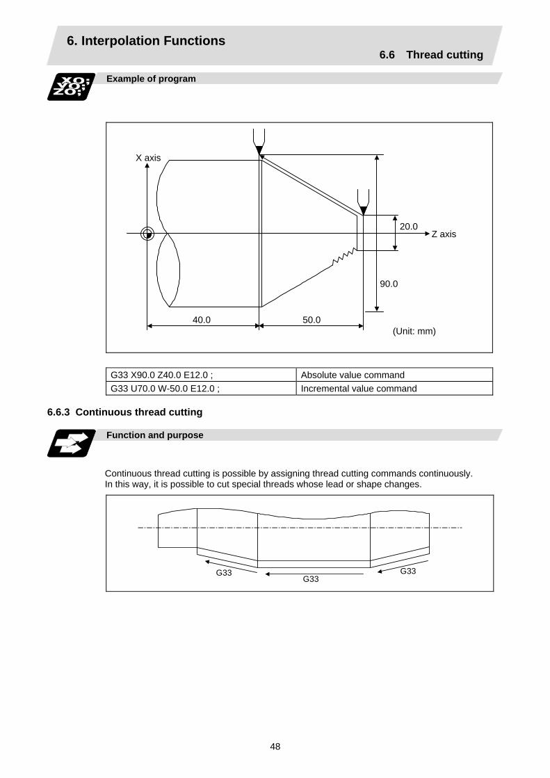
6. Interpolation Functions 6.6 Thread cutting
48
Example of program
40.0 50.0
90.0
20.0 Z axis
X axis
(Unit: mm)
G33 X90.0 Z40.0 E12.0 ; Absolute value command G33 U70.0 W-50.0 E12.0 ; Incremental value command
6.6.3 Continuous thread cutting Function and purpose
Continuous thread cutting is possible by assigning thread cutting commands continuously. In this way, it is possible to cut special threads whose lead or shape changes.
G33 G33G33
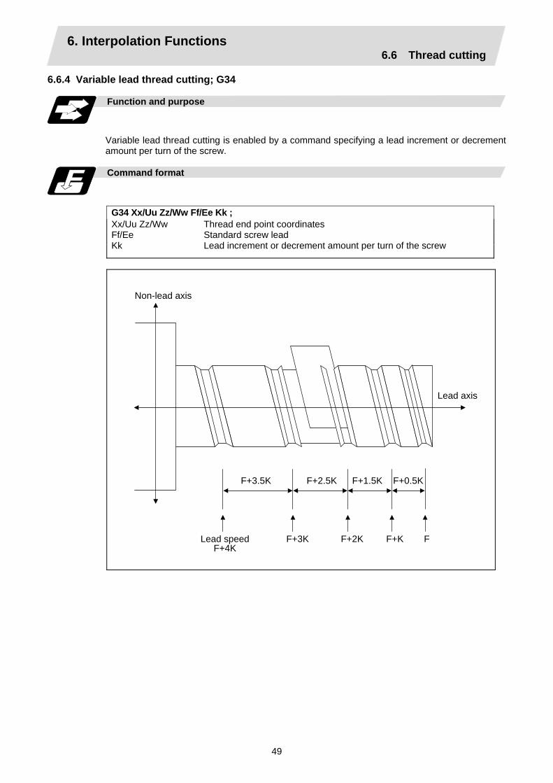
6. Interpolation Functions 6.6 Thread cutting
49
6.6.4 Variable lead thread cutting; G34
Function and purpose
Variable lead thread cutting is enabled by a command specifying a lead increment or decrement amount per turn of the screw.
Command format
G34 Xx/Uu Zz/Ww Ff/Ee Kk ; Xx/Uu Zz/Ww Ff/Ee Kk
Thread end point coordinates Standard screw lead Lead increment or decrement amount per turn of the screw
F+3.5K
Non-lead axis
Lead axis
F+2.5K F+1.5K F+0.5K
Lead speedF+4K
F+3K F+2K F+K F

6. Interpolation Functions 6.6 Thread cutting
50
Detailed description
(1) The command range is as shown below.
Thread cutting metric input Input unit
system B (0.001mm) C (0.0001mm) B/C
Command address F (mm/rev) E (mm/rev) F (mm/rev) E (mm/rev)
Minimum command
unit 1 (=0.0001) (1.=1.0000)
1 (=0.00001)(1.=1.00000)
1 (=0.00001)(1.=1.00000)
1 (=0.000001) (1.=1.000000)
Command range
0.0001 to 999.9999
0.00001 to 999.99999
0.00001 to 99.99999
0.000001 to 99.999999
K (n ∗ mm/rev) n: Number of pitchesSame as F or E (signed)
Thread cutting inch input Input unit
system B (0.0001inch) C (0.00001inch) B/C
Command address F (inch/rev) E (inch/rev) F (inch/rev) E (inch/rev)
Minimum command
unit 1 (=0.000001)(1.=1.000000)
1 (=0.0000001)(1.=1.0000000)
1 (=0.0000001)(1.=1.0000000)
1 (=0.00000001) (1.=1.00000000)
Command range
0.000001 to 99.999999
0.0000001 to 9.9999999
0.0000001 to 9.9999999
0.00000001 to 0.99999999
K (n ∗ inch/rev) n: Number of pitchesSame as F or E (signed)
(2) A positive value of K indicates incremental pitches. Movement amount of one block (n pitches) = (F + K) + (F + 2K) + (F + 3K) + · · + (F + nK)
(3) A negative value of K indicates decremental pitches. Movement amount of one block (n pitches) = (F – K) + (F – 2K) + (F – 3K) + · · + (F – nK)
(4) A program error will occur if the thread lead is not set correctly.
Error number Meaning Remedy P93 Illegal pitch value
• An invalid value is specified for F/E or K in a thread cutting command.
• The last lead goes outside of the F/E command range.
Specify valid values for F/E and K. (Reference 1)
(Reference 1) Last lead = √(F2 + 2KZ) Number of pitches = (–F + last lead)/K Z : Length of lead axis
(5) The other matters are the same as G33. Refer to the section "6.6.1 Constant lead thread cutting; G33".
7. Feed Functions 7.1 Rapid traverse rate
51
7. Feed Functions 7.1 Rapid traverse rate
Function and purpose
The rapid traverse rate can be set independently for each axis. The speed range that can be set is 1mm/min to 1,000,000mm/min when the input setting unit is 1µm. Note that the upper limit speed is limited by the machine specification. Refer to the specifications manual of the machine for the rapid traverse rate settings. Two paths are available during positioning: the interpolation type where the area from the start point to the end point is linearly interpolated or the non-interpolation type where movement proceeds at the maximum speed of each axis. The type is selected by parameter "#1086 G0Intp". The positioning time is the same in each case.
(Note) Rapid traverse override Override can be applied by an external input signal for both manual and automatic rapid
traverse. There are 2 types which are determined by the PLC specifications. Type 1: Override in 4 steps: 1%, 25%, 50% and 100% Type 2: Override in 1% steps from 0% to 100%.
7.2 Cutting feedrate
Function and purpose
The cutting feedrate is assigned with address F and 8 digits. The F8 digits are assigned with a decimal point for a 5-digit integer and a 3-digit fraction. The cutting feedrate is valid for the G01, G02, G03, G33 and G34 commands.
Examples (asynchronous feed)
Feedrate G1 X100. Z100. F200 ; 200.0mm/min F200. or F200.000 gives the same rate.F1 X100. Z100. F123.4 ; 123.4mm/min F1 X100. Z100. F56.789 ; 56.789mm/min
Speed range that can be commanded (when input setting unit is 1µm or 10µm)
Command mode F command range Feed rate command range Remarks
mm/min 0.001 ~ 1000000.000 0.001 ~ 1000000.000 mm/min
inch/min 0.0001 ~ 39370.0787 0.0001 ~ 39370.0787inch/min
°/min 0.001 ~1000000.000 0.001 ~ 1000000.000°/min
(Note 1) A program error (P62) results when there is no F command in the first cutting command
(G01, G02, G03, G33, or G34) after the power has been turned ON.

7. Feed Functions 7.3 F1-digit feed
52
7.3 F1-digit feed
Function and purpose
By setting the F1-digit feed parameter, the feedrate which has been set to correspond to the 1-digit number following the F address serves as the command value. When F0 is assigned, the rapid traverse rate is established and the speed is the same as for G00. (G modal does not change.) When F1 to F5 is assigned, the feedrate set to correspond to the command serves as the command value. The command greater than F6 is considered to be the normal cutting feedrate. The F1-digit command is valid only in a G01, G02 or G03 modal. The F1-digit command can also be used for fixed cycle.
Detailed description
Set the corresponding speed of F1 to F5 with the base specification parameters "#1185 spd_F1" to "#1189 spd_F5" respectively. Operation alarm "104" will occur when the feedrate is 0. (1) Operation method
(a) Make the F1-digit command valid. (Set the base specification parameter "#1079 F1digt" to 1.)
(b) Set F1 to F5. (Base specification parameter "1185 spd_F1" to "#1189 spd_F5")
(2) Special notes (a) Use of both the F1-digit command and normal cutting feedrate command is possible when
the F1-digit is valid. (Example 1)
F0 Rapid traverse rate F1 to F5 F1-digit F6 or more Normal cutting feedrate command
(b) F1 to F5 are invalid in the G00 mode and the rapid traverse rate is established instead.
(c) If F0 is used in the G02 or G03 mode, a program error (P121) will result.
(d) When F1. to F5. (with decimal point) are assigned, the 1mm/min to 5mm/min direct commands are established instead of the F1-digit command.
(e) When the commands are used with the millimeter or degree units, the feedrate set to correspond to F1 to F5 serves as the assigned speed mm (°)/min.
(f) When the commands are used with inch units, one-tenth of the feedrate set correspond to F1 to F5 serves at the assigned speed inch/min.
(g) During a F1-digit command, the F1-digit number and F1-digit command signal are output as the PLC signals.

7. Feed Functions 7.3 F1-digit feed
53
(3) F1-digit and G commands (a) 01 group G command in same block as F1-digit commands
Executed feedrate Modal display rate G modal G0F0 F0G0 Rapid traverse rate 0 G0
G0F1 F1G0 Rapid traverse rate 1 G0
G1F0 F0G1 Rapid traverse rate 0 G1
G1F1 F1G1 F1 contents 1 G1
(b) F1-digit and unmodal commands may be assigned in the same block. In this case, the unmodal command is executed and at the same time the F1-digit modal command is updated.
7. Feed Functions 7.4 Synchronous/asynchronous feed
54
7.4 Synchronous/asynchronous feed; G94, G95
Function and purpose
Using the G95 command, it is possible to assign the feed amount per rotation with an F code. When this command is used, the rotary encoder must be attached to the spindle.
Command format
G94; G95; G94 Per-minute feed (mm/min) (asynchronous feed) G95 Per-rotation feed (mm/rev) (synchronous feed)
The G95 command is a modal command and so it is valid until the G94 command (per-minute feed) is next assigned.
Detailed description
(1) The F code command range is as follows.
The movement amount per spindle rotation with synchronous feed (per-rotation feed) is assigned by the F code and the command range is as shown in the table below.
Metric input
Input command unit
system B (0.001mm) C (0.0001mm)
Command mode Per-minute feed Per-rotation feed Per-minute feed Per-rotation feed
Command address F (mm/min) F (mm/rev) F (mm/min) F (mm/rev)
Minimum command unit
1 (= 1.000), (1. = 1.000)
1 (= 0.0001), (1. = 1.0000)
1 (= 1.0000), (1. = 1.0000)
1 (= 0.00001), (1. = 1.00000)
Command range
0.001 ~1000000.000
0.0001 ~999.9999
0.0001 ~100000.0000
0.00001 ~99.99999
Inch input
Input command unit
system B (0.0001inch) C (0.00001inch)
Command mode Per-minute feed Per-rotation feed Per-minute feed Per-rotation feed
Command address F (inch/min) E (inch/rev) F (inch/min) E (inch/rev)
Minimum command unit
1 (= 0.01), (1. = 1.0000)
1 (= 0.000001), (1. = 1.000000)
1 (= 0.01), (1. = 1.00000)
1 (= 0.0000001), (1. = 1.0000000)
Command range
0.0001 ~ 39370.0787
0.000001 ~ 99.999999
0.00001 ~ 3937.00787
0.0000001 ~ 9.9999999

7. Feed Functions 7.4 Synchronous/asynchronous feed
55
(2) The effective speed (actual movement speed of machine) under per-rotation feed conditions is given in the following formula (Formula 1).
FC = F × N × OVR ........... (Formula 1)
Where FC = Effective rate (mm/min, inch/min) F = Commanded speed (mm/rev, inch/rev) N = Spindle rotation speed (r/min) OVR = Cutting feed override
When a multiple number of axes have been commanded at the same time, the effective rate FC in formula 1 applies in the vector direction of the command.
Precautions
(1) The effective rate (mm/min or inch/min), which is produced by converting the commanded
speed, the spindle rotation speed and the cutting feed override into the per-minute speed, appears as the FC on the monitor 1. screen of the setting and display unit.
(2) When the above effective rate exceeds the cutting feed clamp rate, it is clamped at that clamp rate.
(3) If the spindle rotation speed is zero when synchronous feed is executed, operation error "105" results.
(4) During machine lock high-speed processing, the rate will be 1,000,000 mm/min (or 39,370 inch/min, 1,000,000 °/min) regardless of the commanded speed and spindle rotation speed.
(5) Under dry run conditions, asynchronous speed applies and movement results at the externally set speed (mm/min or inch/min).
(6) Whether asynchronous feed (G94) or synchronous feed (G95) is to be established when the power is turned ON or when M02 or M30 is executed can be selected by setting parameter "#1074 I_Sync".

7. Feed Functions 7.5 Feedrate designation and effects on control axes
56
7.5 Feedrate designation and effects on control axes
Function and purpose
It has already been mentioned that a machine has a number of control axes. These control axes can be divided into linear axes which control linear movement and rotation axes which control rotary movement. The feedrate is designed to assign the displacement speed of these axes, and the effect exerted on the tool movement speed which poses problems during cutting differs according to when control is exercised over the linear axes or when it is exercised over the rotation axes. The displacement amount for each axis is assigned separately for each axis by a value corresponding to the respective axis. The feedrate is not assigned for each axis but assigned as a single value. Therefore, when two or more axes are to be controlled simultaneously, it is necessary to understand how this will work for each of the axes involved. The assignment of the feedrate is described with the following related items.
When controlling linear axes
Even when only one machine axis is to be controlled or there are two or more axes to be controlled simultaneously, the feedrate which is assigned by the F code functions as a linear speed in the tool advance direction.
(Example) When the feedrate is designated as "f" and linear axes (X and Z) are to be controlled
X
Zz
x P2 (Tool end point)
Speed in this direction is "f"
P1 (Tool start point)
Feedrate for X axis = f ×
Feedrate for Z axis = f ×
x x2 + z2
z x2 + z2
When only linear axes are to be controlled, it is sufficient to designate the cutting feed in the program. The feedrate for each axis is such that the designated rate is broken down into the components corresponding to the movement amounts.
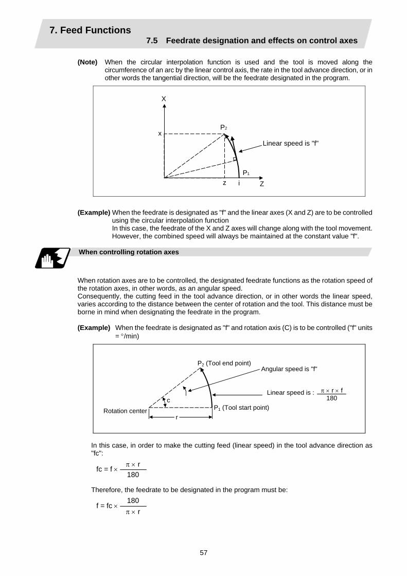
7. Feed Functions 7.5 Feedrate designation and effects on control axes
57
(Note) When the circular interpolation function is used and the tool is moved along the circumference of an arc by the linear control axis, the rate in the tool advance direction, or in other words the tangential direction, will be the feedrate designated in the program.
x
z
X
Zi
P2
P1
Linear speed is "f"
(Example) When the feedrate is designated as "f" and the linear axes (X and Z) are to be controlled
using the circular interpolation function In this case, the feedrate of the X and Z axes will change along with the tool movement.
However, the combined speed will always be maintained at the constant value "f".
When controlling rotation axes
When rotation axes are to be controlled, the designated feedrate functions as the rotation speed of the rotation axes, in other words, as an angular speed. Consequently, the cutting feed in the tool advance direction, or in other words the linear speed, varies according to the distance between the center of rotation and the tool. This distance must be borne in mind when designating the feedrate in the program. (Example) When the feedrate is designated as "f" and rotation axis (C) is to be controlled ("f" units
= °/min)
c
r
P2 (Tool end point)
Rotation center
Angular speed is "f"
P1 (Tool start point)
Linear speed is : π × r × f180
In this case, in order to make the cutting feed (linear speed) in the tool advance direction as "fc":
fc = f × π × r 180
Therefore, the feedrate to be designated in the program must be:
f = fc × 180 π × r

7. Feed Functions 7.5 Feedrate designation and effects on control axes
58
When linear and rotation axes are to be controlled at the same time
The NC unit proceeds in exactly the same way whether linear or rotation axes are to be controlled. When a rotation axis is to be controlled, the numerical value assigned by the coordinate words (C, H) is the angle and the numerical values assignees by the feedrate (F) are all handled as linear speeds. In other words, 1° of the rotation axis is treated as being equivalent to 1mm of the linear axis. Consequently, when both linear and rotation axes are to be controlled simultaneously, the components for each axis of the numerical values assigned by F will be the same as for section (1) above (applying when linear axes are to be controlled). However, although in this case both the size and direction of the speed components based on linear axis control do not vary, the direction of the speed components based on rotation axis control will change along with the tool movement (their size will not change). This means, as a result, that the combined tool advance direction feedrate with vary along with the tool movement.
(Example) When the feedrate is designated as "f" and linear (X) and rotation (C) axes are to be
controlled simultaneously If the X-axis incremental command value is "x" and the C-axis incremental command
value is "c":
P1
θ x
fc
c
fcft
fx
fx
ftr θ
P2
Size and direction are fixed for fx. Size is fixed for fc but direction varies. Both size and direction vary for ft.
Rotation center

7. Feed Functions 7.5 Feedrate designation and effects on control axes
59
X-axis feedrate (linear speed) "fx" and C-axis feedrate (angular speed) "ω" are expressed as: fx = f × ........ (1) ω = f × ........ (2) Linear speed "fc" based on C-axis control is expressed as: fc = ω × ........ (3) If the speed in the tool advance direction at start point P1 is "ft" and the component speeds in the X-axis and Y-axis directions are "ftx" and "fty" respectively. Then these are expressed as: ftx = −rsin ( θ ) × ω + fx ........ (4) fty = −rcos ( θ ) × ω................... (5) Where r is the distance between center of rotation and tool (in mm units), and θ is the angle between the P1 point and the X axis at the center of rotation (in units °). The combined speed "ft" according to formulae (1), (2), (3), (4) and (5) is: ft = ftx2 + fty2 x2 − x × c × rsin ( θ) + ( )2 = f × x2 + c2 Consequently, feedrate "f" designated by the program must be as follows:
f = ft × .......... (7) x2 – x × c × rsin ( θ) + ( )2
180π
180 π × r × c
90π
x2 + c2
"ft" in formula (6) is the speed at the P1 point and the value of θ changes as the C axis rotates, which means that the value of "ft" will also change. Consequently, in order to keep the cutting feed "ft" as constant as possible, the angle of rotation which is designated in one block must be reduced to as low as possible and the extent of the change in the θ value must be minimized.
x x2 + c2
c x2 + c2
π × r 180
π 180
π 180
π 180
π 180
π 180
π90
π × r × c 180
........... (6)
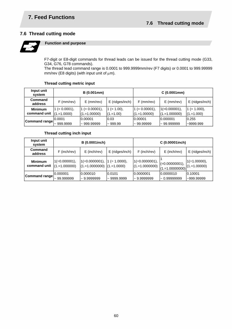
7. Feed Functions 7.6 Thread cutting mode
60
7.6 Thread cutting mode
Function and purpose
F7-digit or E8-digit commands for thread leads can be issued for the thread cutting mode (G33, G34, G76, G78 commands). The thread Iead command range is 0.0001 to 999.9999mm/rev (F7 digits) or 0.0001 to 999.99999 mm/rev (E8 digits) (with input unit of µm).
Thread cutting metric input
Input unit system B (0.001mm) C (0.0001mm)
Command address F (mm/rev) E (mm/rev) E (ridges/inch) F (mm/rev) E (mm/rev) E (ridges/inch)
Minimum command unit
1 (= 0.0001), (1.=1.0000)
1 (= 0.00001), (1.=1.00000)
1 (= 1.00), (1.=1.00)
1 (= 0.00001), (1.=1.00000)
1(=0.000001), (1.=1.000000)
1 (= 1.000), (1.=1.000)
Command range 0.0001 ~ 999.9999
0.00001 ~ 999.99999
0.03 ~ 999.99
0.00001 ~ 99.99999
0.000001 ~ 99.999999
0.255 ~9999.999
Thread cutting inch input
Input unit system B (0.0001inch) C (0.00001inch)
Command address F (inch/rev) E (inch/rev) E (ridges/inch) F (inch/rev) E (inch/rev) E (ridges/inch)
Minimum command unit
1(=0.000001), (1.=1.000000)
1(=0.0000001),(1.=1.0000000)
1 (= 1.0000), (1.=1.0000)
1(=0.0000001),(1.=1.0000000)
1 (=0.00000001), (1.=1.00000000)
1(=1.00000), (1.=1.00000)
Command range 0.000001 ~ 99.999999
0.000010 ~ 9.9999999
0.0101 ~ 9999.9999
0.0000001 ~ 9.9999999
0.0000010 ~ 0.99999999
0.10001 ~999.99999
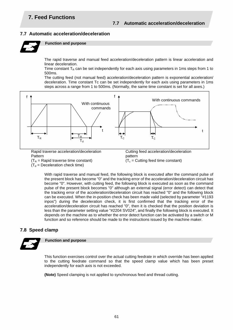
7. Feed Functions 7.7 Automatic acceleration/deceleration
61
7.7 Automatic acceleration/deceleration
Function and purpose
The rapid traverse and manual feed acceleration/deceleration pattern is linear acceleration and linear deceleration. Time constant TR can be set independently for each axis using parameters in 1ms steps from 1 to 500ms. The cutting feed (not manual feed) acceleration/deceleration pattern is exponential acceleration/ deceleration. Time constant Tc can be set independently for each axis using parameters in 1ms steps across a range from 1 to 500ms. (Normally, the same time constant is set for all axes.)
With continuous commands
With continuous commands
TR
f
t
TC
f
tTR Td
TC
Rapid traverse acceleration/deceleration Pattern (TR = Rapid traverse time constant) (Td = Deceleration check time)
Cutting feed acceleration/deceleration pattern (Tc = Cutting feed time constant)
With rapid traverse and manual feed, the following block is executed after the command pulse of the present block has become "0" and the tracking error of the acceleration/deceleration circuit has become "0". However, with cutting feed, the following block is executed as soon as the command pulse of the present block becomes "0" although an external signal (error detect) can detect that the tracking error of the acceleration/deceleration circuit has reached "0" and the following block can be executed. When the in-position check has been made valid (selected by parameter "#1193 inpos") during the deceleration check, it is first confirmed that the tracking error of the acceleration/deceleration circuit has reached "0", then it is checked that the position deviation is less than the parameter setting value "#2204 SV024", and finally the following block is executed. It depends on the machine as to whether the error detect function can be activated by a switch or M function and so reference should be made to the instructions issued by the machine maker.
7.8 Speed clamp Function and purpose
This function exercises control over the actual cutting feedrate in which override has been applied to the cutting feedrate command so that the speed clamp value which has been preset independently for each axis is not exceeded. (Note) Speed clamping is not applied to synchronous feed and thread cutting.

7. Feed Functions 7.9 Exact stop check
62
7.9 Exact stop check; G09
Function and purpose
In order for roundness to be prevented during corner cutting and for machine shock to be alleviated when the tool feedrate changes suddenly, there are times when it is desirable to start the commands in the following block once the in-position state after the machine has decelerated and stopped or the elapsing of the deceleration check time has been checked. The exact stop check function is designed to accomplish this purpose. The parameter "#1193 inpos" among the base specifications parameters enables control to be exercised either by the deceleration check time or in-position state. The in-position state is valid when "#1193 inpos" is set to 1. The in-position width is set into parameter "#2224 SV024" on the servo parameter screen by the machine maker.
Command format
G09 G01 (G02, G03) ;
The exact stop check command G09 has an effect only with the cutting command (G01 ~ G03) in its particular block.
Example of program
N001 G09 G01 X100.000 F150 ; The commands in the following block are started
once the deceleration check time or in-position state has been checked after the machine has decelerated and stopped.
N002 Z100.000 ;
N002
N001
Fig. 1 Exact stop check result
X axis
Z axis
f (Commanded speed)
Time
N001
N002Without G09
Tool
Solid line indicates speed pattern with G09 command.Broken line indicates speed pattern without G09 command.
With G09

7. Feed Functions 7.9 Exact stop check
63
Detailed description
(1) With continuous cutting feed
Ts
Fig. 2 Continuous cutting feed command
Previous block Next block
(2) With cutting feed in-position check
Fig. 3 Block joint with cutting feed in-position check
Ts Ts
Previous block Next block
Lc (in-position width)
In Figs. 2 and 3:
Ts = Cutting feed acceleration/deceleration time constant Lc = In-position width As shown in Fig. 3, the in-position width "Lc" can be set into the servo parameter "#2224 SV024" as the remaining distance (shaded area in Fig. 3) of the previous block when the next block is started. The in-position width is designed to reduce the roundness at the workpiece corners to below the constant value.
Lc Next block
Previous block
To eliminate corner roundness, set the servo parameter "#2224 SV024" to zero and perform an in-position check or assign the dwell command (G04) between blocks.

7. Feed Functions 7.9 Exact stop check
64
(3) With deceleration check
(a) With linear acceleration/deceleration
Ts
Td
Previous block Next block
Ts : Acceleration/deceleration time constant Td : Deceleration check time Td = Ts + ( 0 ~ 14ms)
(b) With exponential acceleration/deceleration
Ts
Td
Previous block Next block
Ts : Acceleration/deceleration time constant Td : Deceleration check time Td = 2 × Ts + ( 0 ~ 14ms)
(c) With exponential acceleration/linear deceleration
2 x Ts
Td Ts
Previous block Next block
Ts : Acceleration/deceleration time constant Td : Deceleration check time Td = 2 × Ts + ( 0 ~ 14ms)
The time required for the deceleration check during cutting feed is the longest among the cutting feed deceleration check times of each axis determined by the cutting feed acceleration/deceleration time constants and by the cutting feed acceleration/ deceleration mode of the axes commanded simultaneously. (Note 1) To execute exact stop check in a fixed cycle cutting block, insert command G09
into the fixed cycle subprogram.
7. Feed Functions 7.10 Exact stop check mode
65
7.10 Exact stop check mode ; G61
Function and purpose
Whereas the G09 exact stop check command checks the in-position status only for the block in which the command has been assigned, the G61 command functions as a modal. This means that deceleration will apply at the end points of each block to all the cutting commands (G01 to G03) subsequent to G61 and that the in-position status will be checked. G61 is released by automatic corner override (G62), tapping mode (G63), or cutting mode (G64).
Command format
G61 ;
In-position check is executed in the G61 block, and thereafter, the in-position check is executed at the end of the cutting command block is executed until the check mode is canceled.

7. Feed Functions 7.11 Automatic corner override
66
7.11 Automatic corner override ; G62
Function and purpose
With this command, when cutting with tool radius compensation, an override is automatically applied to the feedrate to reduce the load during inside corner cutting or during inside cutting of automatic corner R. Automatic corner override is valid until the nose R compensation cancel (G40), exact stop check mode (G61), tapping mode (G63), or cutting mode (G64) command is issued.
Command format
G62 ;
Machining inside corners
When cutting an inside corner as in Fig. 1, the machining allowance amount increases and a greater load is applied to the tool. To remedy this, override is applied automatically within the corner set range, the feedrate is reduced, the increase in the load is reduced and cutting is performed effectively. However, this function is valid only when finished shapes are programmed.
θ
Ci
Fig. 1
S
workpiece
Machining allowance
Machining allowanceProgrammed path(finished shape)
Workpiece surface shape
Nose R center path
Tool
θ : Max. angle at inside cornerCi : Deceleration range (IN)
Deceleration range
(1)(2)
(3)
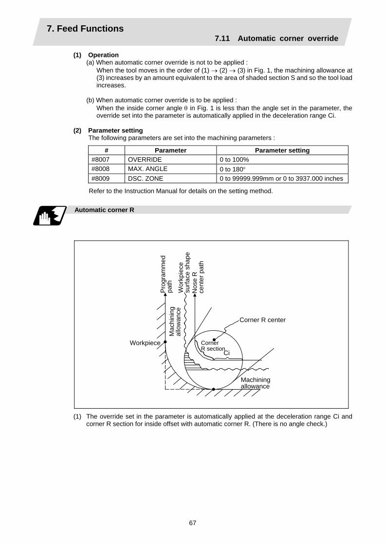
7. Feed Functions 7.11 Automatic corner override
67
(1) Operation (a) When automatic corner override is not to be applied :
When the tool moves in the order of (1) → (2) → (3) in Fig. 1, the machining allowance at (3) increases by an amount equivalent to the area of shaded section S and so the tool load increases.
(b) When automatic corner override is to be applied :
When the inside corner angle θ in Fig. 1 is less than the angle set in the parameter, the override set into the parameter is automatically applied in the deceleration range Ci.
(2) Parameter setting
The following parameters are set into the machining parameters :
# Parameter Parameter setting #8007 OVERRIDE 0 to 100% #8008 MAX. ANGLE 0 to 180° #8009 DSC. ZONE 0 to 99999.999mm or 0 to 3937.000 inches
Refer to the Instruction Manual for details on the setting method.
Automatic corner R
CiWorkpiece
Pro
gram
med
pa
th
Mac
hini
ng
allo
wan
ce
Wor
kpie
ce
surfa
ce s
hape
N
ose
R
cent
er p
ath
Corner R section
Machining allowance
Corner R center
(1) The override set in the parameter is automatically applied at the deceleration range Ci and corner R section for inside offset with automatic corner R. (There is no angle check.)

7. Feed Functions 7.11 Automatic corner override
68
Application example
(1) Linear − linear corner
θ
Ci
Program
Nose R center
Tool
The override set in the parameter is applied at Ci.
(2) Linear − arc (outside offset) corner
θ
Ci
Program Nose R center
Tool
The override set in the parameter is applied at Ci.
(3) Arc (inside offset) − linear corner
θ
Ci
Program
Nose R center
ToolTool
The override set in the parameter is applied at Ci. (Note) The deceleration range Ci where the override is applied is the length of the arc with an
arc command.

7. Feed Functions 7.11 Automatic corner override
69
(4) Arc (inside offset) − arc (outside offset) corner
θN1
Ci
N2Program
Nose R center
The override set in the parameter is applied at Ci.
Relation with other functions
Function Override at corner
Cutting feed override Automatic corner override is applied after cutting feed override has been applied.
Override cancel Automatic corner override is not canceled by override cancel. Speed clamp Valid after automatic corner override Dry run Automatic corner override is invalid. Synchronous feed Automatic corner override is applied to the synchronous feedrate.Thread cutting Automatic corner override is invalid. G31 skip Program error results with G31 command during nose R
compensation. Machine lock Valid Machine lock high speed Automatic corner override is invalid. G00 Invalid G01 Valid G02, G03 Valid

7. Feed Functions 7.11 Automatic corner override
70
Precautions
(1) Automatic corner override is valid only in the G01, G02, and G03 modes; it is not effective in
the G00 mode. When switching from the G00 mode to the G01 (or G02 or G03) mode at a corner (or vice versa), automatic corner override will not be applied at that corner in the G00 block.
(2) Even if the automatic corner override mode is entered, the automatic corner override will not be applied until the nose R compensation mode is entered.
(3) Automatic corner override will not be applied on a corner where the nose R compensation is started or canceled.
Automatic corner override will not be applied
Start-up block Program Cancel block
Nose R center
(4) Automatic corner override will not be applied on a corner where the nose R compensation I, K vector command is issued.
(G41 X_Z_I_K_;)
Block containing I, K vector command
Program
Automatic corner override will not be applied
Nose R center
(5) Automatic corner override will not be applied when intersection calculation cannot be executed. Intersection calculation cannot be executed in the following case.
(a) When the movement command block does not continue for four or more times.
(6) The deceleration range with an arc command is the length of the arc.
(7) The inside corner angle, as set by parameter, is the angle on the programmed path.
(8) Automatic corner override will not be applied when the maximum angle in the parameter is set to 0 or 180.
(9) Automatic corner override will not be applied when the override in the parameter is set to 0 or 100.

7. Feed Functions 7.12 Tapping mode
71
7.12 Tapping mode ; G63 Function and purpose
The G63 command allows the control mode best suited for tapping to be entered, as indicated below :
1. Cutting override is fixed at 100%. 2. Deceleration commands at joints between blocks are invalid. 3. Feed hold is invalid. 4. Single block is invalid. 5. In-tapping mode signal is output.
G63 is released by the exact stop check mode (G61), automatic corner override (G62), or cutting mode (G64) command.
Command format
G63 ; 7.13 Cutting mode ; G64 Function and purpose
The G64 command allows the cutting mode in which smooth cutting surfaces are obtained to be established. Unlike the exact stop check mode (G61), the next block is executed continuously with the machine not decelerating and stopping between cutting feed blocks in this mode. G64 is released by the exact stop check mode (G61), automatic corner override (G62), or tapping mode (G63) command.
This cutting mode is established in the initialized status.
Command format
G64 ;

8. Dwell 8.1 Per-second dwell
72
8. Dwell
The G04 command can delay the start of the next block. The dwell remaining time can be canceled by adding the multistep skip function.
8.1 Per-second dwell ; G04
Function and purpose
The machine movement is temporarily stopped by the program command to make the waiting time state. Therefore, the start of the next block can be delayed. The waiting time state can be canceled by inputting the skip signal.
Command format
G04 X/U__ ; or G04 P__ ; X/U, P Dwell time
The input command unit for the dwell time depends on the parameter. In addition to the address P and X, the address U (actually, the address corresponding to the X-axis designated with the #1014 incax) can be used. Note that this is invalid when the #1076 AbsInc is set to 0.
Detailed description
(1) When designating the dwell time with X/U, the decimal point command is valid. (2) The dwell time command range is as follows. 0.001 ~ 99999.999 (s) (3) The dwell time setting unit applied when there is no decimal point can be made 1s by setting 1
in the parameter #1078 Decpt2. This is effect only for X/U and P for which the decimal command is valid.
(4) When a cutting command is in the previous block, the dwell command starts calculating the dwell time after the machine has decelerated and stopped. When it is commanded in the same block as an M, S, T or B command, the calculation starts simultaneously.
(5) The dwell is valid during the interlock. (6) The dwell is valid even for the machine lock. (7) The dwell can be canceled by setting the parameter #1173 dwlskp beforehand. If the set skip
signal is input during the dwell time, the remaining time is discarded, and the following block will be executed.

8. Dwell 8.1 Per-second dwell
73
Previous block cutting command
Next block
Dwell command
Dwell time
Example of program
Dwell time (s) Command
#1078 Decpt2 = 0 #1078 Decpt2 = 1 G04 X500 ; 0.5 500 G04 X5000 ; 5 5000 G04 X5. ; 5 5 G04 X#100 ; 1000 1000 G04 U500 ; 0.5 500 G04 U5000 ; 5 5000 G04 U5. ; 5 5 G04 U#100 ; 100 1000 G04 P5000 ; 5 5000 G04 P12.345 ; 12.345 12.345 G04 P#100 ; 1000 1000
(Note 1) The above examples are the results under the following conditions. • Input setting unit 0.001mm or 0.0001inch • #100 = 1000 ; (Note 2) If the input setting unit is 0.0001inch, the X before G04 will be multiplied by 10. For
example for "X5. G04 ;", the dwell time will be 50 seconds. Precautions and restrictions
(1) When using this function, command X/U after G04 in order to make sure that the dwell is
based on X/U.

9. Miscellaneous Functions 9.1 Miscellaneous functions (M8-digits BCD)
74
9. Miscellaneous Functions 9.1 Miscellaneous functions (M8-digits BCD)
Function and purpose
The miscellaneous (M) functions are also known as M functions, and they include such numerically controlled machine functions as spindle forward and reverse rotation, operation stop and coolant ON/OFF. These functions are designated by an 8-digit number (0 to 99999999) following the address M with this controller, and up to 4 groups can be commanded in a single block.
(Example) G00 Xx Mm1 Mm2 Mm3 Mm4 ;
When five or more commands are issued, only the last four will be valid. The output signal is an 8-digit BCD code and start signal. The eight commands of M00, M01, M02, M30, M96, M97, M98 and M99 are used as auxiliary commands for specific objectives and so they cannot be used as general auxiliary commands. This therefore leaves 92 miscellaneous functions which are usable as such commands. Reference should be made to the instructions issued by the machine maker for the actual correspondence between the functions and numerical values. When the M00, M01, M02, and M30 functions are used, the next block is not read into the pre-read buffer due to pre-read inhibiting. When an M function is specified together with a movement command in the same block, there are two possible sequences in which the commands are executed, as follows. The machine specifications determine which sequence applies.
(1) The M function is executed after the movement command.
(2) The M function is executed at the same time as the movement command. Which of these sequences actually applies depends on the machine specifications.
Processing and completion sequences are required in each case for all M commands except M96, M97, M98 and M99. The 8 M functions used for specific purposes will now be described.
Program stop : M00
When the NC has read this function, it stops reading the next block. Whether such machine functions as the spindle rotation and coolant supply are stopped or not differs according to the machine in question. Re-start is enabled by pressing the automatic start button on the machine operation board. Whether resetting can be initiated by M00 depends on the machine specifications.
Optional stop : M01
If the M01 command is read when the optional stop switch on the machine operation board is ON, reading of the next block will stop and the same effect as with the M00 function will apply.
(Example)
~
Optional stop switch command is ignored.
N10 G00 X1000 ; N11 M01 ;
Stops at N11 when switch is ON Next command (N12) is executed without stopping at N11 when switch is OFF
N12 G01 X2000 Z3000 F600 ;
~

9. Miscellaneous Functions 9.1 Miscellaneous functions (M8-digits BCD)
75
Program end : M02 or M30
This command is normally used in the final block for completing the machining, and so it is primarily used for indexing the machining program. Whether indexing the machining program or not depends on the machine specifications. Depending on the machine specifications, the system is reset by the M02 or M30 command upon completion of indexing the machining program and any other commands issued in the same block. (Although the contents of the command position display counter are not cleared by this reset action, the modal commands and compensation amounts are canceled.) The next operation stops when the indexing the machining program is completed (the in-automatic operation lamp goes off). To restart the unit, the automatic start button must be pressed or similar steps must be taken.
(Note 1) Independent signals are also output respectively for the M00, M01, M02 and M30 commands and these outputs are each reset by pressing the reset key.
(Note 2) M02 or M30 can be assigned by manual data input (MDI). At this time, commands can be issued simultaneously with other commands.
Macro interrupt : M96, M97
M96 and M97 are M codes for user macro interrupt control. The M code for user macro interrupt control is processed internally, and is not output externally. To use M96 and M97 as a miscellaneous code, change the setting to another M code with the parameter (#1109 subs_M and #1110 M96_M, #1111 M97_M).
Subprogram call/completion : M98, M99
These commands are used as the return instructions from branch destination subprograms and branches to subprograms. M98 and M99 are processed internally and so M code signals and strobe signals are not output.
Internal processing with M00/M01/M02/M30 commands
Internal processing suspends pre-reading when the M00, M01, M02 or M30 command has been read. Indexing operation other than M02/M03 and the initialization of modals by resetting differ according the machine specifications.

9. Miscellaneous Functions 9.2 2nd miscellaneous functions (A8-digits, B8-digits or C8-digits)
76
9.2 2nd miscellaneous functions (A8-digits, B8-digits or C8-digits)
Function and purpose
These serve to assign the indexing table positioning and other such functions. In this controller, they are assigned by an 8-digit number from 0 to 99999999 following address A, B or C. The machine maker determines which codes correspond to which positions. When the A, B and C functions are commanded in the same block as movement commands, there are 2 sequences in which the commands are executed, as below. The machine specifications determine which sequence applies.
(1) The A, B or C function is executed after the movement command.
(2) The A, B or C function is executed simultaneously with the movement command.
Processing and completion sequences are required for all 2nd miscellaneous functions. The table below given the various address combinations. It is not possible to use an address which is the same for the axis name of an additional axis and 2nd miscellaneous function.
Additional axis name
2nd miscellaneous function A B C
A × B × C ×
(Note) When "A" has been assigned as the 2nd miscellaneous function address, the following commands cannot be used.
(1) Geometric commands
(2) Deep hole drilling cycle (2) command

10. Spindle Functions 10.1 Spindle function (S2-digits BCD)
77
10. Spindle Functions 10.1 Spindle function (S2-digits BCD) ..... During standard PLC specifications
Function and purpose
The spindle functions are also known simply as S functions and they assign the spindle rotation speed. In this controller, they are assigned with a 2-digit number following the S code ranging from 0 to 99, and 100 commands can be designated. In actual fact, however, it depends on the machine specifications as to how many of these 100 functions are used and which numbers correspond to which functions, and thus reference should be made to the instruction issued by the machine manufacturer. When a number exceeding 2 digits is assigned, the last 2 digits will be valid. When S functions are commanded in the same block as movement commands, there are 2 sequences in which the commands are executed, as below. The machine specifications determine which sequence applies.
(1) The S function is executed after the movement command.
(2) The S function is executed simultaneously with the movement command.
Processing and completion sequences are required for all S commands from S00 to S99. 10.2 Spindle function (S6-digits Analog)
Function and purpose
When the S6-digits function is added, commands with a 6-dight number following the S code can be designated. Other commands conform to the S2-digits function. Always select S command binary output when using this function. In this function, the appropriate gear signal, voltage corresponding to the commanded spindle rotation speed, and start signal are output by the numeric command of the six digits following the S code. Processing and completion sequences are required for all S commands. The analog signal specifications are given below.
(1) Output voltage................. 0 to 10V
(2) Resolution......................... 1/4096 (2–12)
(3) Load conditions…………. 10kΩ
(4) Output impedance………. 220Ω If the parameters for up to 4 gear stages are set in advance, the gear stage corresponding to the S command will be selected and the gear signal will be output. The analog voltage is calculated in accordance with the input gear signal.
(1) Parameters corresponding to individual gears………… Limit rotation speed, maximum rotation speed, shift rotation speed and tapping rotation speed
(2) Parameters corresponding to all gears………………. Orientation rotation speed, minimum rotation speed
10. Spindle Functions 10.3 Spindle functions (S8-digits)
78
10.3 Spindle functions (S8-digits)
Function and purpose
These functions are assigned with an 8-digit (0 ~ 99999999) number following the address S, and one group can be assigned in one block. The output signal is a 32-bit binary data with sign and start signal. Processing and completion sequences are required for all S commands.
10. Spindle Functions 10.4 Multiple spindle control I
79
10.4 Multiple spindle control I 10.4.1 Multiple spindle control
Function and purpose
Spindle rotation command for up to 7 spindles is provided. Although the S∗∗∗∗∗ command is normally used to designate the spindle rotation speed, the Sn=∗∗∗∗∗ command is also used for multiple spindle control. S commands can be issued from the machining program of any part systems. Number of usable spindles differ the machine model, confirm the specifications of the model used.
Command format
Sn=∗∗∗∗∗ ; S6-digit binary data. n ∗∗∗∗∗
Designate the spindle number with one numeric character. Rotation speed or constant surface speed command value.
Detailed description
(1) Each spindle command is delimited by the details of n.
(Example)
S1 = 3500 ; 1st spindle 3500(r/min) command S2 = 1500 : 2nd spindle 1500(r/min) command S3 = 2000 ; 3rd spindle 2000(r/min) command S4 = 2500 : 4th spindle 2500(r/min) command S5 = 2000 ; 5th spindle 2000(r/min) command S6 = 3000 : 6th spindle 3000(r/min) command S7 = 3500 ; 7th spindle 3500(r/min) command
(2) Multiple spindles can be commanded in one block.
(3) If two or more commands are issued to the same spindle in a block, the command issued last will be valid.
(Example) S1 = 3500 S1 = 3600 S1 = 3700 ; S1 = 3700 will be valid.
(4) The S∗∗∗∗∗ command and Sn=∗∗∗∗∗ command can be used together. The spindle targeted for the S∗∗∗∗∗ command is normally the 1st spindle, however, the S∗∗∗∗∗
command can be used for 2nd or following spindle according to the spindle selection command.
(5) The commands for each spindle can be commanded from the machining program of any part systems. The spindles will rotate with the speed commanded last. If the S commands are issued from two or more part systems, the command from the part system of largest No. will be valid.
(6) As for C6 T-type and L-type, C64 T-type, and C64T T-type, the multiple spindles control can not be used in a part system. A program error (P33) will occur when the Sn=∗∗∗∗∗ command is issued. Refer to "10.4.2 Spindle selection command" for details.

10. Spindle Functions 10.4 Multiple spindle control I
80
10.4.2 Spindle selection command
Function and purpose
This function controls which spindle’s rotation the cutting follows, in addition, designates the spindle to be selected when "S∗∗∗∗∗∗" command is issued.
Command format
G43.1; G44.1;
Selected spindle (nth spindle) control mode ON (Selected with parameter) 2nd spindle control mode ON
Detailed description
(1) G43.1 and G44.1 are modal G codes.
(2) The spindle control mode entered when the power is turned ON or reset depends on the parameter setting. Designate the spindle No. to be selected in G43.1 modal with the parameter (basic specifications parameter "#1199 Sselect"). This parameter is provided for every part system to set as follows.
# Items Details Setting range (unit) 1199 (PR)
Sselect Select initial spindle control
Select the initial condition of spindle control when power is turned ON or reset.
0: Selected spindle control mode (G43.1)
1: 2nd spindle control mode (G44.1)
21049 SPname Designate the spindle No. selected for the G43.1 modal in each part system.
0: 1st spindle 4: 4th spindle1: 1st spindle 5: 5th spindle2: 2nd spindle 6: 6th spindle3: 3rd spindle 7: 7th spindle
Reset the NC after changing "#1199 Sselect " and "#21049 SPname" parameters. It is no use
to turn the power OFF once and ON again. (3) As for C6 L-type, T-type, C64 T-type and C64T T-type, there are following restrictions; · A program error (P34) will occur if G44.1 command is issued. · No data can be set to "#1199 Sselect". "0" is set when the NC power is turned ON. · Only one spindle than is selected with "#21049 SPname" can be commanded as "S∗∗∗∗∗"
in each part system. · A program error (P33) will occur if the "S0=∗∗∗∗∗" command is issued. (4) If the S command is issued in the same as the spindle selection commands (G43.1, and
G44.1), which spindle the S command is valid for depends on the order that G43.1, G44.1, and S command are issued. When S command precedes the G codes, it follows the G43.1 / G44.1 mode before S command is issued. When G codes precede, it follows the G43.1 / G44.1 mode issued in the same block.
(5) G43.1 and G44.1 commands can be issued from every part system.

10. Spindle Functions 10.4 Multiple spindle control I
81
Relation with other functions
(1) The following functions change after the spindle selection command.
(a) Per rotation command (synchronous feed) Even if F is commanded in the G95 mode, the per rotation feedrate for the selected spindle (nth spindle) will be applied during G43.1 mode and for the 2nd spindle during G44.1 mode.
(b) S commands (S∗∗∗∗∗, Sn=∗∗∗∗∗), constant surface speed control, thread cutting
Function G43.1 mode G44.1 mode S command during G97/G96 constant surface speed control Upper limit / Lower limit of spindle rotation speed command during constant surface speed control (G92 S_ Q) Thread cutting
Command control for the selected spindle (nth spindle). (Note 1)
Command control for the 2nd spindle.
(Note 1) The spindle selected during G43.1 mode depends on the parameter "#21049 SPname".
(2) The Sn=∗∗∗∗∗ command can be used to command the other spindle even if it is commanded during G43.1 or G44.1 mode. Note that the rotation speed designation will be applied for such command even if the G96 mode is ON.
(Example) When "SPname" = 0;
Rotation speed G43.1; 1st spindle 2nd spindle G97 S1000;
: 0(r/min)
S2 = 2000; :
1000(r/min)
G96 S100; :
2000(r/min)
S2 = 2500; :
2500(r/min)
G44.1 S200; :
100(m/min)
(Note 2) S1 = 3000;
:
200(m/min)
G97 S4000; :
3000(r/min)
4000(r/min)
(Note 2) The constant surface speed control will be switched to the 2nd spindle by G44.1 command. Therefore, the 1st spindle retains its rotation speed as that of "G44.1 S200;" command. The 1st spindle rotation speed will be 3000 (r/min) when "S1=3000;" command is issued.
10. Spindle Functions 10.5 Constant surface speed control
82
10.5 Constant surface speed control; G96, G97
Function and purpose
These commands automatically control the spindle rotation speed in line with the changes in the radius coordinate values as cutting proceeds in the diametrical direction, and they serve to keep the cutting point speed constant during the cutting.
Command format
G96 Ss Pp; Constant surface speed ON Ss Pp
Surface speed (1 to 999999 m/min) Designation of constant surface speed control axis
G97; Constant surface speed cancel
Detailed description
(1) The constant surface speed control axis is set by parameter (#1181 G96_ax).
0 : Fixed at 1st axis (P command invalid) 1 : 1st axis 2 : 2nd axis 3 : 3rd axis
(2) When the above-mentioned parameter is not zero, the constant surface speed control axis can be designated by address P. (Example) When G96_ax = 1
Program Constant surface speed control axis G96 S100 ; 1st axis G96 S100 P3 ; 3rd axis
(3) Example of selection program and operation
G90 G96 G01 X50. Z100. S200 ;
~ G97 G01 X50. Z100. F300 S500 ;
~ M02 ; The modal returns to the initial value.
(4) Constant surface speed control can be commanded on the selected spindle (nth spindle) / the 2nd spindle. Select which spindle (the selected spindle or 2nd one) the commands are made to by the spindle selection G codes (G43.1 and G44.1). Select which spindle (the selected spindle or 2nd one) is valid as the initial state with the parameter (base specifications parameter "#1199 Sselect").
(5) Select whether calculating the surface speed at rapid traverse command is performed constantly or only at the block end poing.
The spindle rotation speed is controlled so that the surface speed is 200m/min.
The spindle rotation speed is controlled to 500 r/min.
10. Spindle Functions 10.6 Spindle clamp speed setting
83
10.6 Spindle clamp speed setting; G92
Function and purpose
The maximum clamp rotation speed of the spindle can be assigned by address S following G92 and the minimum clamp rotation speed by address Q.
Command format
G92 Ss Qq ; Ss Qq
Maximum clamp rotation speed Minimum clamp rotation speed
Detailed description
(1) Besides this command, parameters can be used to set the rotation speed range up to 4 stages
in 1 r/min units to accommodate gear selection between the spindle and spindle motor. The lowest upper limit and highest lower limit are valid among the rotation speed ranges based on the parameters and based on "G92 Ss Qq ;".
(2) Set in the parameters "#1146 Sclamp" and "#1227 aux11/bit5" whether to carry out rotation
speed clamp only in the constant surface speed mode or even when the constant surface speed is canceled.
(Note) G92S command and rotation speed clamp operation
Sclamp = 0 Sclamp = 1 aux11/bit5 = 0 aux11/bit5 = 1 aux11/bit5 = 0 aux11/bit5 = 1
In G96 Rotation speed clamp command Rotation speed clamp command
Rotation speed clamp command
Command In G97 Spindle rotation speed command
Rotation speed clamp command
Rotation speed clamp command
In G96 Rotation speed clamp execution Rotation speed clamp execution
Rotation speed clamp executionOperation
In G97 No rotation speed clamp Rotation speed clamp execution
No rotation speed clamp
(3) Spindle clamp speed command can be commanded on the selected spindle (nth spindle) / the 2nd spindle. Select which spindle (the selected spindle or 2nd one) the commands are made to by the spindle selection G codes (G43.1 and G44.1). Select which spindle (the selected spindle or 2nd one) is valid as the initial state with the parameter (base specifications parameter "#1199 Sselect").

10. Spindle Functions 10.7 Spindle synchronous control I
84
10.7 Spindle synchronous control I; G114.1
Function and purpose
In a machine having two or more spindles, this function controls the rotation speed and phase of one spindle (basic spindle) in synchronization with the rotation of the other spindle (synchronous spindle). The function is used "when the rotation speed of the two spindles must be matched, for example, if a workpiece grasped by the 1st spindle is to be grasped by a 2nd spindle", or "if the spindle rotation speed has to be changed when one workpiece is grasped by both the 1st and 2nd spindles". With the spindle synchronous control function I, designation of spindles and controls start / stop of synchronization are commanded using G codes in the machining program.
Command format
(1) Spindle synchronous control ON (G114.1)
This command designates the basic spindle and synchronous spindle, and synchronizes the two designated spindles. By commanding the synchronous spindle phase shift amount, the phases of the basic spindle and synchronous spindle can be aligned.
G114.1 H_ D_ R_ A_ ; H_ Basic spindle selection D_ Synchronous spindle selection R_ Spindle synchronization phase shift amount A_ Spindle synchronization acceleration/deceleration time constant
(2) Spindle synchronous control cancel (G113)
This command cancels the synchronous state of the two spindles rotating in synchronization with the spindle synchronous command.
G113 ;
Add- ress
Meaning of address
Command range (unit) Remarks
H Basic spindle selection Select the No. of the spindle to be used as the basic spindle from the two spindles.
1 to 7 1: 1st spindle 2: 2nd spindle : 7: 7th spindle
• A program error (P35) will occur if a value exceeding the command range or spindle No. without specifications is commanded.
• A program error (P33) will occur if there is no command.
• A program error (P610) will occur if a spindle not serially connected is commanded.
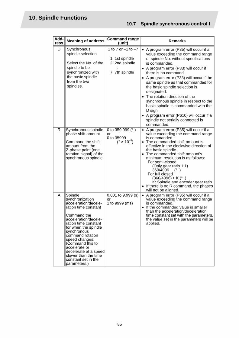
10. Spindle Functions 10.7 Spindle synchronous control I
85
Add- ress Meaning of address Command range
(unit) Remarks
D Synchronous spindle selection Select the No. of the spindle to be synchronized with the basic spindle from the two spindles.
1 to 7 or –1 to –7 1: 1st spindle 2: 2nd spindle : 7: 7th spindle
• A program error (P35) will occur if a value exceeding the command range or spindle No. without specifications is commanded.
• A program error (P33) will occur if there is no command.
• A program error (P33) will occur if the same spindle as that commanded for the basic spindle selection is designated.
• The rotation direction of the synchronous spindle in respect to the basic spindle is commanded with the D sign.
• A program error (P610) will occur if a spindle not serially connected is commanded.
R Synchronous spindle phase shift amount Command the shift amount from the Z-phase point (one rotation signal) of the synchronous spindle.
0 to 359.999 (° ) or 0 to 35999 (° × 10–3)
• A program error (P35) will occur if a value exceeding the command range is commanded.
• The commanded shift amount is effective in the clockwise direction of the basic spindle.
• The commanded shift amount's minimum resolution is as follows:
For semi-closed (Only gear ratio 1:1) 360/4096 (° ) For full closed (360/4096) ∗ K (° ) K: Spindle and encoder gear ratio• If there is no R command, the phases
will not be aligned. A Spindle
synchronization acceleration/decele- ration time constant Command the acceleration/decele- ration time constant for when the spindle synchronous command rotation speed changes. (Command this to accelerate or decelerate at a speed slower than the time constant set in the parameters.)
0.001 to 9.999 (s)or 1 to 9999 (ms)
• A program error (P35) will occur if a value exceeding the command range is commanded.
• If the commanded value is smaller than the acceleration/deceleration time constant set with the parameters, the value set in the parameters will be applied.

10. Spindle Functions 10.7 Spindle synchronous control I
86
Rotation and rotation direction
(1) The rotation speed and rotation direction of the basic spindle and synchronous spindle during
spindle synchronous control are the rotation speed and rotation direction commanded for the basic spindle. Note that the rotation direction of the synchronous spindle can be reversed from the basic spindle through the program.
(2) The basic spindle's rotation speed and rotation direction can be changed during spindle synchronous control.
(3) The synchronous spindle's rotation command is also valid during spindle synchronous control. When spindle synchronous control is commanded, if neither a forward run command nor
reverse run command is commanded for the synchronous spindle, the synchronization standby state will be entered without starting the synchronous spindle's rotation. If the forward run command or reverse run command is input in this state, the synchronous spindle will start rotation. The synchronous spindle's rotation direction will follow the direction commanded in the program.
If spindle stop is commanded for the synchronous spindle during spindle synchronization control (when both the forward run and reverse run commands are turned OFF), the synchronous spindle rotation will stop.
(4) The rotation speed command (S command) and constant surface speed control are invalid for the synchronous spindle during spindle synchronous control. Note that the modal is updated, so these will be validated when the spindle synchronization is canceled.
(5) The constant surface speed can be controlled by issuing a command to the basic spindle even during spindle synchronous control.

10. Spindle Functions 10.7 Spindle synchronous control I
87
Rotation synchronization
(1) When rotation synchronization control (command with no R address) is commanded with the
G114.1 command, the synchronous spindle rotating at a random rotation speed will accelerate or decelerate to the rotation speed commanded beforehand for the basic spindle, and will enter the rotation synchronization state.
(2) If the basic spindle's commanded rotation speed is changed during the rotation synchronization state, acceleration/deceleration will be carried out while maintaining the synchronization state following the spindle acceleration/deceleration time constants set in the parameters, and the commanded rotation speed will be achieved.
(3) In the rotation synchronization state, the basic spindle can be controlled to the constant surface speed even when two spindles are grasping one workpiece.
(4) Operation will take place in the following manner.
M23 S2=750 ; : M03 S1=1000 ; : G114.1 H1 D-2 ; : S1=500 ; : G113 ;
... Forward rotate 2nd spindle (synchronous spindle) at 750
r/min (speed command) ... Forward rotate 1st spindle (basic spindle) at 1000 r/min
(speed command) ... Synchronize 2nd spindle (synchronous spindle) to 1st
spindle (basic spindle) with reverse run ... Change 1st spindle (basic spindle) rotation speed to 500
r/min ... Cancel spindle synchronization
<Operation>
1000
750
500
0
–500
–750
–1000
2nd spindle (synchronous spindle) forward run
1st spindle (basic spindle) forward run
2nd spindle (synchronous spindle) reverse run synchronization
1st spindle (basic spindle) rotation speed change
Spindle synchronization cancel
Basic spindle Synchronous spindle
Forward run
Reverse run
Rotation speed (r/min)
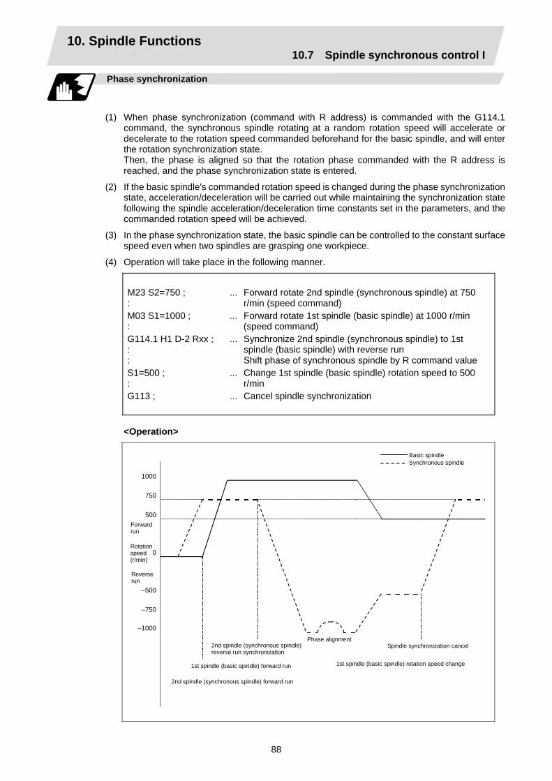
10. Spindle Functions 10.7 Spindle synchronous control I
88
Phase synchronization
(1) When phase synchronization (command with R address) is commanded with the G114.1
command, the synchronous spindle rotating at a random rotation speed will accelerate or decelerate to the rotation speed commanded beforehand for the basic spindle, and will enter the rotation synchronization state.
Then, the phase is aligned so that the rotation phase commanded with the R address is reached, and the phase synchronization state is entered.
(2) If the basic spindle's commanded rotation speed is changed during the phase synchronization state, acceleration/deceleration will be carried out while maintaining the synchronization state following the spindle acceleration/deceleration time constants set in the parameters, and the commanded rotation speed will be achieved.
(3) In the phase synchronization state, the basic spindle can be controlled to the constant surface speed even when two spindles are grasping one workpiece.
(4) Operation will take place in the following manner.
M23 S2=750 ; : M03 S1=1000 ; : G114.1 H1 D-2 Rxx ; : : S1=500 ; : G113 ;
... Forward rotate 2nd spindle (synchronous spindle) at 750
r/min (speed command) ... Forward rotate 1st spindle (basic spindle) at 1000 r/min
(speed command) ... Synchronize 2nd spindle (synchronous spindle) to 1st
spindle (basic spindle) with reverse run Shift phase of synchronous spindle by R command value
... Change 1st spindle (basic spindle) rotation speed to 500 r/min
... Cancel spindle synchronization
<Operation>
1000
750
500
0
–500
–750
–1000
Basic spindle Synchronous spindle
2nd spindle (synchronous spindle) forward run
1st spindle (basic spindle) forward run
2nd spindle (synchronous spindle) reverse run synchronization
1st spindle (basic spindle) rotation speed change
Spindle synchronization cancel
Forward run
Reverse run
Phase alignment
Rotation speed (r/min)

10. Spindle Functions 10.7 Spindle synchronous control I
89
Cautions on programming
(1) To enter the rotation synchronization mode while the basic spindle and synchronous spindle
are chucking the same workpiece, turn the basic spindle and synchronous spindle rotation commands ON before turning the spindle synchronous control mode ON.
$1 (1st part system) $2 (2nd part system) : : M6 ; 1st spindle chuck close : : M25 S2=0 ; 2nd spindle stops at S=0 : : !2 ; !1 ; Waiting between part
systems M5 S1=0 ; 1st spindle stops at S=0 M15 ; 2nd spindle chuck close : M24 ; 2nd spindle rotation
command ON M3 ; 1st spindle rotation
command ON :
!2 ; !1 ; Waiting between part
systems : G114.1 H1 D-2 ; Rotation synchronization : : mode ONS1=1500 ; Synchronous rotation at
S=1500 :
: : S1=0 ; G113 ;
Both spindles stop Synchronization mode OFF
(2) To chuck the same workpiece with the basic spindle and synchronous spindle in the phase
synchronization mode, align the phases before chucking.
$1 $2 : : M6 ; 1st spindle chuck close : : : M3 S1=1500 ; 1st spindle rotation
command ON :
: G114.1 H1 D-2 R0 ; Phase synchronization : : mode ON: M24 ; 2nd spindle rotation
command ON : : : M15 ; 2nd spindle chuck close
(Note 1) : :
(Note 1) Close the chuck after confirming that the spindle phase synchronization complete
signal (X42A) has turned ON (phase alignment complete).
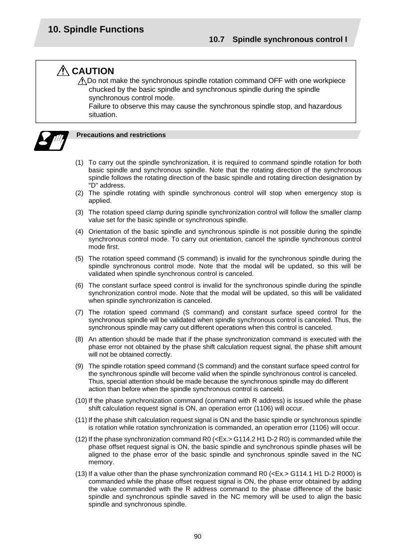
10. Spindle Functions 10.7 Spindle synchronous control I
90
CAUTION Do not make the synchronous spindle rotation command OFF with one workpiece chucked by the basic spindle and synchronous spindle during the spindle synchronous control mode. Failure to observe this may cause the synchronous spindle stop, and hazardous situation.
Precautions and restrictions
(1) To carry out the spindle synchronization, it is required to command spindle rotation for both
basic spindle and synchronous spindle. Note that the rotating direction of the synchronous spindle follows the rotating direction of the basic spindle and rotating direction designation by "D" address.
(2) The spindle rotating with spindle synchronous control will stop when emergency stop is applied.
(3) The rotation speed clamp during spindle synchronization control will follow the smaller clamp value set for the basic spindle or synchronous spindle.
(4) Orientation of the basic spindle and synchronous spindle is not possible during the spindle synchronous control mode. To carry out orientation, cancel the spindle synchronous control mode first.
(5) The rotation speed command (S command) is invalid for the synchronous spindle during the spindle synchronous control mode. Note that the modal will be updated, so this will be validated when spindle synchronous control is canceled.
(6) The constant surface speed control is invalid for the synchronous spindle during the spindle synchronization control mode. Note that the modal will be updated, so this will be validated when spindle synchronization is canceled.
(7) The rotation speed command (S command) and constant surface speed control for the synchronous spindle will be validated when spindle synchronous control is canceled. Thus, the synchronous spindle may carry out different operations when this control is canceled.
(8) An attention should be made that if the phase synchronization command is executed with the phase error not obtained by the phase shift calculation request signal, the phase shift amount will not be obtained correctly.
(9) The spindle rotation speed command (S command) and the constant surface speed control for the synchronous spindle will become valid when the spindle synchronous control is canceled. Thus, special attention should be made because the synchronous spindle may do different action than before when the spindle synchronous control is canceld.
(10) If the phase synchronization command (command with R address) is issued while the phase shift calculation request signal is ON, an operation error (1106) will occur.
(11) If the phase shift calculation request signal is ON and the basic spindle or synchronous spindle is rotation while rotation synchronization is commanded, an operation error (1106) will occur.
(12) If the phase synchronization command R0 (<Ex.> G114.2 H1 D-2 R0) is commanded while the phase offset request signal is ON, the basic spindle and synchronous spindle phases will be aligned to the phase error of the basic spindle and synchronous spindle saved in the NC memory.
(13) If a value other than the phase synchronization command R0 (<Ex.> G114.1 H1 D-2 R000) is commanded while the phase offset request signal is ON, the phase error obtained by adding the value commanded with the R address command to the phase difference of the basic spindle and synchronous spindle saved in the NC memory will be used to align the basic spindle and synchronous spindle.

10. Spindle Functions 10.7 Spindle synchronous control I
91
(14) The phase offset request signal will be ignored when the phase shift calculation request signal is ON.
(15) The phase error of the basic spindle and synchronous spindle saved in the NC is valid only when the phase shift calculation signal is ON and for the combination of the basic spindle selection (H_) and synchronous spindle (D_) commanded with the rotation synchronization command (no R address).
For example, if the basic spindle and synchronous spindle phase error is saved as "G114.1 H1 D-2 ;", the saved phase error will be valid only when the phase offset request signal is ON and "G114.1 H1 D_2 R∗∗∗ ;" is commanded. If "G114.1 H2 D-1 R∗∗∗ ;" is commanded in this case, the phase shift amount will not be calculated correctly.
(16) The phase error of the basic spindle and synchronous spindle saved in the NC is retained until the spindle synchronization phase shift calculation, in other words, until the rotation synchronous control command completes with the phase shift calculation request signal is ON.
(17) Synchronous tapping can not be used during spindle synchronous mode.
(18) When the spindle synchronous control commands are being issued with the PLC I/F method (#1300 ext36/bit7 OFF), a program error (P610) will occur if the spindle synchronous control is commanded with G114.1/G113.
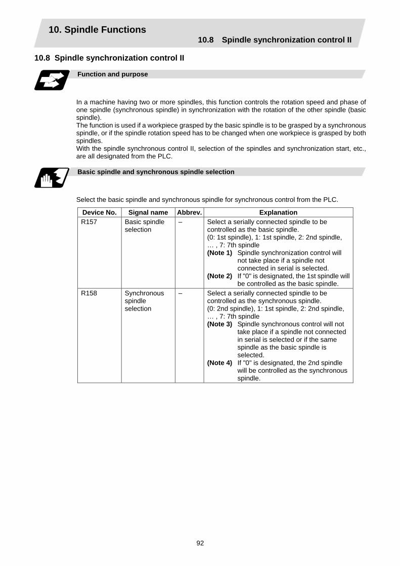
10. Spindle Functions 10.8 Spindle synchronization control II
92
10.8 Spindle synchronization control II
Function and purpose
In a machine having two or more spindles, this function controls the rotation speed and phase of one spindle (synchronous spindle) in synchronization with the rotation of the other spindle (basic spindle). The function is used if a workpiece grasped by the basic spindle is to be grasped by a synchronous spindle, or if the spindle rotation speed has to be changed when one workpiece is grasped by both spindles. With the spindle synchronous control II, selection of the spindles and synchronization start, etc., are all designated from the PLC.
Basic spindle and synchronous spindle selection
Select the basic spindle and synchronous spindle for synchronous control from the PLC.
Device No. Signal name Abbrev. Explanation R157 Basic spindle
selection – Select a serially connected spindle to be
controlled as the basic spindle. (0: 1st spindle), 1: 1st spindle, 2: 2nd spindle, … , 7: 7th spindle (Note 1) Spindle synchronization control will
not take place if a spindle not connected in serial is selected.
(Note 2) If "0" is designated, the 1st spindle will be controlled as the basic spindle.
R158 Synchronous spindle selection
– Select a serially connected spindle to be controlled as the synchronous spindle. (0: 2nd spindle), 1: 1st spindle, 2: 2nd spindle, … , 7: 7th spindle (Note 3) Spindle synchronous control will not
take place if a spindle not connected in serial is selected or if the same spindle as the basic spindle is selected.
(Note 4) If "0" is designated, the 2nd spindle will be controlled as the synchronous spindle.
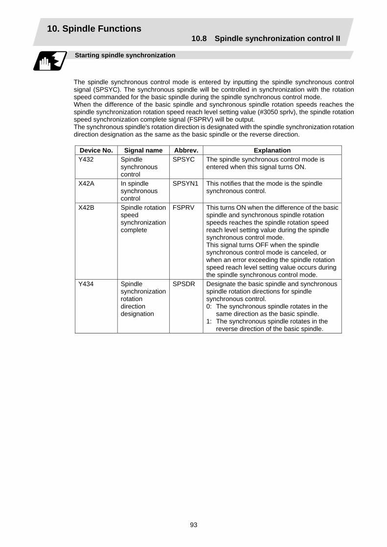
10. Spindle Functions 10.8 Spindle synchronization control II
93
Starting spindle synchronization
The spindle synchronous control mode is entered by inputting the spindle synchronous control signal (SPSYC). The synchronous spindle will be controlled in synchronization with the rotation speed commanded for the basic spindle during the spindle synchronous control mode. When the difference of the basic spindle and synchronous spindle rotation speeds reaches the spindle synchronization rotation speed reach level setting value (#3050 sprlv), the spindle rotation speed synchronization complete signal (FSPRV) will be output. The synchronous spindle's rotation direction is designated with the spindle synchronization rotation direction designation as the same as the basic spindle or the reverse direction.
Device No. Signal name Abbrev. Explanation Y432 Spindle
synchronous control
SPSYC The spindle synchronous control mode is entered when this signal turns ON.
X42A In spindle synchronous control
SPSYN1 This notifies that the mode is the spindle synchronous control.
X42B Spindle rotation speed synchronization complete
FSPRV This turns ON when the difference of the basic spindle and synchronous spindle rotation speeds reaches the spindle rotation speed reach level setting value during the spindle synchronous control mode. This signal turns OFF when the spindle synchronous control mode is canceled, or when an error exceeding the spindle rotation speed reach level setting value occurs during the spindle synchronous control mode.
Y434 Spindle synchronization rotation direction designation
SPSDR Designate the basic spindle and synchronous spindle rotation directions for spindle synchronous control. 0: The synchronous spindle rotates in the
same direction as the basic spindle. 1: The synchronous spindle rotates in the
reverse direction of the basic spindle.

10. Spindle Functions 10.8 Spindle synchronization control II
94
Spindle phase alignment
Spindle phase synchronization starts when the spindle phase synchronous control signal (SPPHS) is input during the spindle synchronization control mode. The spindle phase synchronization complete signal is output when the spindle synchronization phase reach level setting value (#3051 spplv) is reached. The synchronous spindle's phase shift amount can also be designated from the PLC.
Device No. Signal name Abbrev. Explanation Y433 Spindle phase
synchronous control
SPPHS Spindle phase synchronization starts when this signal is turned ON during the spindle synchronous control mode. (Note 1) If this signal is turned ON in a mode
other than the spindle synchronous control mode, it will be ignored.
X42C Spindle phase synchronization complete
FSPPH This signal is output when the spindle synchronization phase reach level is reached after starting spindle phase synchronization.
R159 Phase shift amount setting
– Designate the synchronous spindle's phase shift amount. Unit: 360°/4096
Spindle synchronous control (Y432)
Spindle synchronization complete (X42B)
In spindle synchronous control (X42A)
Spindle phase synchronous control (Y433)
Spindle phase synchronization complete (X42C)
Spindle phase synchronization complete ON
(Note 2)
Spindle phase synchronous control ON
Spindle synchronization complete ON
Spindle phasesynchronous control OFF
Spindle synchronization control ON
Spindle synchronous control OFF
(Note 2) Turns OFF temporarily to change the rotation speed during phase synchronization.

10. Spindle Functions 10.8 Spindle synchronization control II
95
Calculating the spindle synchronization phase shift amount and requesting phase offset
The spindle phase shift amount calculation function obtains and saves the phase difference of the basic spindle and synchronous spindle by turning the PLC signal ON during spindle synchronization. When calculating the spindle phase shift, the synchronous spindle can be rotated with the handle, so the relation of the phases between the spindles can also be adjusted visually. If the spindle phase synchronization control signal is input while the phase offset request signal (SSPHF) is ON, the phases will be aligned using the position shifted by the saved phase shift amount as a reference. This makes aligning of the phases easier when grasping the material that the shape of one end differ from another end.
Device No. Signal name Abbrev. Explanation Y435 Phase shift
calculation request
SSPHM If spindle synchronization is carried out while this signal is ON, the phase difference of the basic spindle and synchronous spindle will be obtained and saved.
Y436 Phase offset request
SSPHF If spindle phase synchronization is carried out while this signal is ON, the phases will be aligned using the position shifted by the saved phase shift amount as a basic position.
R55 Phase difference output
– The delay of the synchronous spindle in respect to the basic spindle is output. Unit: 360°/4096 (Note 1) If either the basic spindle or
synchronous spindle has not passed through the Z phase, etc., and the phase cannot be calculated, –1 will be output.
(Note 2) This data is output only while calculating the phase shift or during spindle phase synchronization.
R59 Phase offset data
– The phase difference saved with phase shift calculation is output. Unit: 360°/4096 (Note 3) This data is output only during
spindle synchronous control.
Spindle synchronous control (Y436)
Spindle synchronization complete (X42B)
In spindle synchronous control (X42A)
Spindle synchronouscontrol ON
Phase shift calculation request (Y435)
The phase difference in this interval is saved. (The synchronous spindle can be controlled with the handle.)
Spindle synchronous control OFF
Phase shift calculation request ON
Phase shift calculation request OFF
(Note 4) The phases cannot be aligned while calculating the phase shift. (Note 5) The synchronous spindle cannot be rotated with the handle when the manual operation
mode is set to the handle mode.

10. Spindle Functions 10.8 Spindle synchronization control II
96
Chuck close signal
The synchronous spindle side carries out droop compensation while the chuck is opened, and aligns itself with the basic spindle. However, when the chuck is closed, the droop compensation is added, and the synchronization error with the base increases. Droop compensation is prevented with the chuck close signal and the position where the chuck is grasped is maintained with position compensation.
Device No. Signal name Abbrev. Explanation Y431 Chuck close SPCMPC This turns ON when the chuck of both spindles
are closed. This signal is ON while the basic spindle and the synchronous spindle grasp the same workpiece.
X42D Chuck close confirmation
SPCMP This turns ON when the chuck close signal is received during the spindle synchronous control mode.
Chuck open Chuck closeChuck close
Spindle synchronous control (Y432)
Error temporary cancel (Y437)
In spindle synchronous control (X42A)
Error canceled
Synchronous spindle chuck
Spindle synchronization complete (X42B)
Basic spindle chuck Chuck close Chuck close Chuck openChuck close confirmation
Chuck open confirmation
Chuck close (Y431)
(Note 1) Use the error temporary cancel only when there is still an error between the spindle and synchronization with the chuck close signal.
Error temporary cancel function
When spindle synchronization is carried out while grasping the workpiece with the basic spindle and rotating, if the chuck is closed to grasp the workpiece with the synchronous spindle, the speed will fluctuate due to external factors and an error will occur. If spindle synchronization is continued without compensating this error, the workpiece will twist. This torsion can be prevented by temporarily canceling this error.
Device No. Signal name Abbrev. Explanation Y437 Error temporary
cancel SPDRP0 The error is canceled when this signal is ON.
(Note 1) Even if the chuck close signal (Y431) is OFF, the error will be canceled while this signal (Y437) is ON.
(Note 2) Turn this signal ON after the both chucks of basic spindle side and synchronous spindle side are closed to grasp the workpiece. Turn this signal OFF if even one chuck is opened.

10. Spindle Functions 10.8 Spindle synchronization control II
97
Phase error monitor
The phase error can be monitored during spindle phase synchronization.
Device No. Signal name Abbrev. Explanation R56 Phase error
monitor – The phase error during spindle phase
synchronous control is output as a pulse unit.R57 Phase error
monitor (lower limit value)
– The lower limit value of the phase error during spindle phase synchronous control is output as a pulse unit.
R59 Phase error monitor (upper limit value)
– The upper limit value of the phase error during spindle phase synchronous control is output as a pulse unit.
Multi-speed acceleration/deceleration
Up to eight steps of acceleration/deceleration time constants for spindle synchronization can be selected according to the spindle rotation speed.
Sptc1
Sptc2
Sptc3
(1) (2) (3)
Rotation speed
Time
(1) Time required from stopped state to sptc1 setting rotation speed
spt ∗ (sptc1/maximum rotation speed) (2) Time required from sptc1 to sptc2 setting rotation speed spt ∗ ((sptc2–sptc1)/maximum rotation speed) ∗ spdiv1 (3) Time required from sptc2 to sptc3 setting rotation speed spt ∗ ((sptc3–sptc2)/maximum rotation speed) ∗ spdiv2

10. Spindle Functions 10.8 Spindle synchronization control II
98
Precautions and restrictions
(1) When carrying out spindle synchronization, a rotation command must be issued to both the
basic spindle and synchronous spindle. The synchronous spindle's rotation direction will follow the basic spindle rotation direction and spindle synchronization rotation direction designation regardless of whether a forward or reverse run command is issued.
(2) The spindle synchronization control mode will be entered even if the spindle synchronization control signal is turned ON while the spindle rotation speed command is ON. However, synchronous control will not actually take place. Synchronous control will start after the rotation speed is commanded to the basic spindle, and then the spindle synchronization complete signal will be output.
(3) The spindle rotating with spindle synchronization control will stop when emergency stop is applied.
(4) An operation error will occur if the spindle synchronization control signal is turned ON while the basic spindle and synchronous spindle designations are illegal.
(5) The rotation speed clamp during spindle synchronization control will follow the smaller clamp value set for the basic spindle or synchronous spindle.
(6) Orientation of the basic spindle and synchronous spindle is not possible during the spindle synchronization. To carry out orientation, turn the spindle synchronization control signal OFF first.
(7) The rotation speed command is invalid for the synchronous spindle during the spindle synchronization. Note that the modal is rewritten, thus, the commanded rotation speed will be validated after spindle synchronization is canceled.
(8) The constant surface speed control is invalid for the synchronous spindle during the spindle synchronization. However, note that the modal is rewritten and it will be valid after spindle synchronization is canceled.
(9) If the phase offset request signal is turned ON before the phase shift is calculated and then spindle phase synchronization is executed, the shift amount will not be calculated and incorrect operation results.
(10) The spindle rotation speed command (S command) and the constant surface speed control for the synchronous spindle will become valid when the spindle synchronous control is canceled. Thus, special attention should be made because the synchronous spindle may do different action than before when the spindle synchronous control is canceled.
(11) The spindle Z-phase encoder position parameter (sppst) is invalid (ignored) when phase offset is carried out. This parameter will be valid when the phase offset request signal is OFF.
(12) If spindle phase synchronization is started while the phase shift calculation request signal is ON, the error "M01 OPERATION ERROR 1106" will occur.
(13) Turn the phase shift calculation request signal ON when the basic spindle and synchronous spindle are both stopped. If the phase shift calculation request signal is ON while either of the spindles is rotating, the error "M01 OPERATION ERROR 1106" will occur.
(14) The phase offset request signal is ignored when the phase shift calculation request signal (Y435) is ON.
(15) "M01 OPERATION ERROR 1106" will occur when a spindle No. out of specifications is designated in the R registers to set the basic spindle and the synchronous spindle, or when the spindle synchronous control signal (Y432) is turned ON with R resister value illegal.
(16) The phase shift amount saved in the NC is held until the next phase shift is calculated. (This value is saved even when the power is turned OFF.)
(17) Synchronous tapping can not be used during spindle synchronous mode.

11. Tool Functions 11.1 Tool functions (T8-digits BCD)
99
11. Tool Functions 11.1 Tool functions (T8-digits BCD)
Function and purpose
Tool functions are also known as T functions, and are used to designate the tool Nos. and tool compensation Nos. The designations are made by the 8 digits (0 to 99999999) following the address T. These commands are used with the higher-order six or seven digits indicating the tool No., and the lower-order one or two digits indicating the compensation No. Which is to be used is determined by setting in the parameter "#1098 TLno.". The usable T commands differ according to each machine, so refer to the instruction manual issued by the machine maker. One set of T commands can be issued in one block.
Command format
T ∗∗∗∗∗∗∗ ∗ ;
Tool compensation number Tool number
T ∗∗∗∗∗∗ ∗∗ ;
Tool compensation number Tool number
Reference should be made to the instructions issued by the machine maker for the correspondence between the actual tools and the tool numbers commanded in the program. BCD codes and start signals are output. When the T functions are commanded in the same block as movement commands, there are 2 sequences in which the commands are executed, as below. The machine specifications determine which sequence applies.
(a) The T function is executed after the movement command.
(b) The T function is executed simultaneously with the movement command.
Processing and completion sequences are required for all T commands.

12. Tool Offset Functions 12.1 Tool offset
100
12. Tool Offset Functions
12.1 Tool offset
Function and purpose
Tool offset is performed by the T functions which are commanded with the 3-, 4- or 8-digit number following address T. There are two types of tool offset: tool length offset and tool nose wear offset. There are two ways to issue the commands: the tool length offset and tool nose wear offset are designated by the last 1 or 2 digits of the T command or the tool nose wear offset is assigned by the last 1 or 2 digits of the T command and the tool length offset by the tool number. Parameter "#1098 TLno." is used to switch between them. Parameter "#1097 T1digt" is also used to select the last 1 or 2 digits for the offset. One group of T command can be assigned in a block.
Command format
(1) When designating the tool length and tool nose wear offset number using the last 1 or 2 digits
of the T command.
T ∗∗∗∗∗∗∗ ∗ ;
Tool length offset + tool nose wear offset Tool number
T ∗∗∗∗∗∗ ∗∗ ;
Tool length offset + tool nose wear offset Tool number
(2) When differentiating between the tool length offset number and tool nose wear offset number
T ∗∗∗∗∗∗∗ ∗ ;
Tool nose wear offset Tool number + tool length offset
T ∗∗∗∗∗∗ ∗∗ ;
Tool nose wear offset Tool number + tool length offset
The lower two digits of the tool No. are the tool length offset No.

12. Tool Offset Functions 12.1 Tool offset
101
12.1.1 Tool offset start
Detailed description
There are two ways to execute tool offset and these can be selected by parameter: executing offset when the T command is executed and executing offset in the block with a movement command without performing offset when the T command is executed.
(1) Offset with T command execution
N1
N2 Tool path after offset
Offset amount
Programmed machining path
N1 T0101 ; N2 X100. Z200. ;
Tool length offset and tool nose wear offset are conducted simultaneously.
(Note 1) The movement applying to offset with the T command execution is rapid traverse in a G00 modal and cutting feed with other modals.
(Note 2) When performing offset with T command execution, the path is offset as a linear movement in a circular modal.
(Note 3) When performing offset with T command execution, offset will not function until the arrival of any G command except those listed below when the T command has been assigned in the same block as the G commands listed below.
G04 : Dwell G10 : Program tool offset input/program parameter input G11 : Program parameter input mode cancel G65 : User macro simple call G92 : Coordinate system setting
(2) Offset with movement command
N1
N2
Tool path after offset
Offset amount
Programmed machining path
N1 T0101 ; N2 X100. Z200. ;
Tool length offset and tool nose wear offset are conducted simultaneously.
(Note 1) When performing offset with a movement command, offset is applied if the offset amount is lower than the parameter "#1084 RadErr" when offset is performed for the first time with a circular command. If the amount is higher, the program error (P70) results. (This also applies when the arc command and T command are in the same block for offsetting with T command execution.)

12. Tool Offset Functions 12.2 Tool length offset
102
12.2 Tool length offset
Tool length offset amount setting
This function offsets the tool length with respect to the programmed basic position. This position may generally be set to either the center position of the turret or the tool nose position of the basic tool.
(1) Center position of turret
X
Z
Basic position (basic point)
X-axis tool length offset amount
Z-axis tool lengthoffset amount
(2) Tool nose position of basic tool
X
Z
Basic point
Tool used for machining X-axis tool lengthoffset amount
Z-axis tool lengthoffset amount
Basic tool
Tool length offset number change
When tool numbers are changed, the tool length offset corresponding to the new tool numbers are added to the movement amounts in the machining program.
N5
N2 N3
N4
Offset amount (old)
Programmed machining path
Offset amount(new)
Offset tool path
N1 T0100 ; N2 G1 X10.0 Z10.0 F100 ; N3 G1 X13.0 Z15.0 F20.0 ; N4 T0200 ; N5 G1 X13.0 Z20.0 F25.0 ;
In this example, the tool length is offset with the tool number and offset is performed in the block with the movement command.
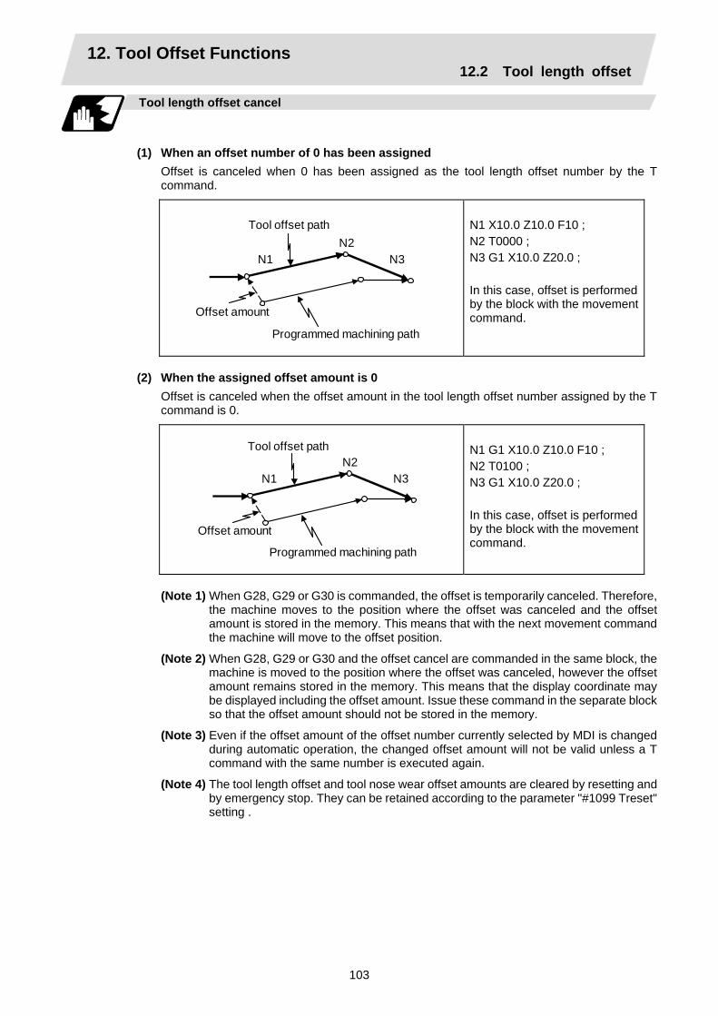
12. Tool Offset Functions 12.2 Tool length offset
103
Tool length offset cancel
(1) When an offset number of 0 has been assigned
Offset is canceled when 0 has been assigned as the tool length offset number by the T command.
N2N3N1
Tool offset path
Offset amount
Programmed machining path
N1 X10.0 Z10.0 F10 ; N2 T0000 ; N3 G1 X10.0 Z20.0 ; In this case, offset is performed by the block with the movement command.
(2) When the assigned offset amount is 0
Offset is canceled when the offset amount in the tool length offset number assigned by the T command is 0.
N2
N3N1
Tool offset path
Offset amount
Programmed machining path
N1 G1 X10.0 Z10.0 F10 ; N2 T0100 ; N3 G1 X10.0 Z20.0 ; In this case, offset is performed by the block with the movement command.
(Note 1) When G28, G29 or G30 is commanded, the offset is temporarily canceled. Therefore,
the machine moves to the position where the offset was canceled and the offset amount is stored in the memory. This means that with the next movement command the machine will move to the offset position.
(Note 2) When G28, G29 or G30 and the offset cancel are commanded in the same block, the machine is moved to the position where the offset was canceled, however the offset amount remains stored in the memory. This means that the display coordinate may be displayed including the offset amount. Issue these command in the separate block so that the offset amount should not be stored in the memory.
(Note 3) Even if the offset amount of the offset number currently selected by MDI is changed during automatic operation, the changed offset amount will not be valid unless a T command with the same number is executed again.
(Note 4) The tool length offset and tool nose wear offset amounts are cleared by resetting and by emergency stop. They can be retained according to the parameter "#1099 Treset" setting .

12. Tool Offset Functions 12.3 Tool nose wear offset
104
12.3 Tool nose wear offset
Tool nose wear offset amount setting
The wear sustained by the tool being used can be offset.
X
Z
Tool nose
X-axis tool nose wear offset amount
Z-axis tool nose wear offset amount
Tool nose wear offset cancel
Tool nose wear offset is canceled when 0 has been assigned as the offset number.
N2
N3N1
Tool offset path
Offset amount Programmed machining path
N1 G1 X10.0 Z10.0 F10 ; N2 T0100 ; N3 G1 X10.0 Z20.0 ; In this case, offset is performed in the block with the movement command.
(Note 1) When G28, G29 or G30 is commanded, the offset is temporarily canceled. Therefore, the
machine moves to the position where the offset was canceled and the offset amount is stored in the memory. This means that with the next movement command the machine will move to the offset position.
(Note 2) When G28, G29 or G30 and the offset cancel are commanded in the same block, the machine is moved to the position where the offset was canceled, however the offset amount remains stored in the memory. This means that the display coordinate may be displayed including the offset amount. Issue these command in the separate block so that the offset amount should not be stored in the memory.
(Note 3) Even if the offset amount of the offset number currently selected by MDI is changed during automatic operation, the changed offset amount will not be valid unless a T command with the same number is executed again.
(Note 4) The tool length offset and tool nose wear offset amounts are cleared by resetting and by emergency stop. They can be retained by parameter "#1099 Treset".

12. Tool Offset Functions 12.4 Tool nose radius compensation
105
12.4 Tool nose radius compensation; G40, G41, G42, G46
Function and purpose
The tool nose is generally rounded and so a hypothetical tool nose point is treated as the tool nose for programming purposes. When this is done, an error caused by the tool nose rounding arises during taper cutting or circular cutting between the actually programmed shape and the cutting shape. Tool nose radius compensation is a function for automatically calculating and offsetting this error by setting the tool nose radius value. The command codes enable the offset direction to be fixed or automatically identified.
R
Actual machining shape
Machining shape commanded in program
Hypothetical tool nose point
Tool nose center path at programmed machining shape
Tool nose center
Functions and command formats
Code Function Command format G40 Tool nose radius compensation mode cancel G40 (Xx/Uu Zz/Ww Ii Kk) ; G41 Tool nose radius compensation left mode ON G41 (Xx/Uu Zz/Ww) ; G42 Tool nose radius compensation right mode ON G42 (Xx/Uu Zz/Ww) ; G46 Tool nose radius compensation automatic
direction identification mode ON G46 (Xx/Uu Zz/Ww) ;
(Note 1) By means of the preset hypothetical tool nose point and movement commands in the
machining program, the G46 tool nose radius compensation function automatically identifies the compensation direction and provides tool nose radius compensation.
(Note 2) G40 serves to cancel the tool nose radius compensation mode.

12. Tool Offset Functions 12.4 Tool nose radius compensation
106
Right compensation
Right compensation fixed in G42 mode
Z axis
Automatic identification in G46 mode
Left compensationLeft compen- sation fixed in G41 mode
X axis
(Note 3) Tool nose radius compensation pre-reads the data in the following two movement command blocks (up to 5 blocks when there are no movement commands) and controls the tool nose radius center path by the intersection point calculation method so that it is offset from the programmed path by an amount equivalent to the nose radius.
r Prior to the N1 block execution, the next movement command block is pre-read and the coordinates at the intersection point are calculated.
N3
N2 block
N1 block
(Note 4) In the above figure, "r" is the tool nose radius compensation amount (nose radius). (Note 5) The tool nose radius compensation amount corresponds to the tool length number and it
is preset along with the tool nose point. (Note 6) If there are 4 or more blocks without movement amounts among 5 continuous blocks,
overcutting or undercutting will result. Blocks in which optional block skip is valid are ignored. (Note 7) Tool nose radius compensation is also valid for fixed cycles (G77 ~ G79) and for rough
cutting cycles (G70, G71, G72, G73). However, in the rough cutting cycles, the finished shape with the tool nose radius
compensation applied will be cut with the compensation canceled and, upon completion of the cutting, operation will automatically return to the compensation mode.
(Note 8) With thread cutting commands, compensation is temporarily canceled 1 block before. (Note 9) A tool nose radius compensation (G41 or G42) command can be assigned during tool nose
radius compensation (G46). Compensation does not need to be canceled with G40 at this time.
(Note 10)The compensation plane, movement axes and next advance direction vector follow the plane selection command designated by G17, G18 or G19.
G17 : X-Y plane X, Y, I, J G18 : Z-X plane Z, X, K, I G19 : Y-Z plane Y, Z, J, K
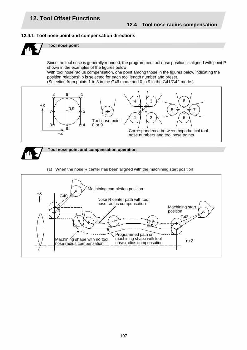
12. Tool Offset Functions 12.4 Tool nose radius compensation
107
12.4.1 Tool nose point and compensation directions
Tool nose point
Since the tool nose is generally rounded, the programmed tool nose position is aligned with point P shown in the examples of the figures below. With tool nose radius compensation, one point among those in the figures below indicating the position relationship is selected for each tool length number and preset. (Selection from points 1 to 8 in the G46 mode and 0 to 9 in the G41/G42 mode.)
PP
1 2
3 4
5
6
7
8
+X 0,9
+Z
1 2
34
5
6
7
8
Tool nose point 0 or 9
Correspondence between hypothetical tool nose numbers and tool nose points
Tool nose point and compensation operation
(1) When the nose R center has been aligned with the machining start position
+X
+Z
G42
G40
r
Machining completion position
Nose R center path with tool nose radius compensation
Machining start position
Machining shape with no toolnose radius compensation
Programmed path ormachining shape with tool nose radius compensation

12. Tool Offset Functions 12.4 Tool nose radius compensation
108
(2) When the tool nose point has been aligned with the machining start position
+X
+Z
G40
r
Machining completion position
Machining shape with no tool nose radius compensation Machining start
position
Nose R tool nose point path withtool nose radius compensation
Programmed path ormachining shape with tool nose radius compensation
G42 or G46
Compensation directions
(1) The compensation direction of the G41/G42 commands is determined by the G41/G42 codes. The direction in a G46 command is automatically determined in accordance with the following table from the relationship between the tool nose points and the commanded movement vectors.
(2) When tool nose radius compensation has been started and the initial movement vector (including G0) corresponds to an "×" mark in the table, the compensation direction cannot be specified and so it is determined by the next movement vector. When the direction cannot be determined even after reading 5 blocks ahead, program error (P156) results.
(3) When an attempt is made to reverse the compensation direction during tool nose radius compensation, program error (P157) results except when the reversal is done in the G00 block. Even if the directions differ before and after the G28, G30 or G53 block, an error will not result since compensation is temporarily canceled. Using a parameter (#8106 G46 reverse axis error evade), the tool can also be moved unchanged in the same compensation direction.

12. Tool Offset Functions 12.4 Tool nose radius compensation
109
(4) When the compensation direction during tool nose radius compensation coincides with an "×" in the table below, the direction complied with the previous compensation direction. Determining the compensation direction by the movement vectors and tool nose point in command G46
Tool nose points Compensation
direction of tool nose
Direction of tool nose advance
Compensation direction of tool nose
Directionof tool nose advance
Right Right Left Left Right Left
Right Left Left Right Right Left
Left Right Right Left Left Right
Left Right Left Left Right Right
Left Left Right Right Left Right
Left Right Right Left Left Right
Right Left Left Right Right Left
Move- ment vector (tool nose points 1 to 4)
Left Left Right Right Left Left
Move- ment vector (tool nose points 5 to 8)
(Note 1) An "×" mark in the tables indicates that the compensation direction is not determined from
the movement vector (tool nose points).
(Note 2) The " " mark denotes a movement vector in the 45° direction. (The other movement vectors are based on this.)
(Note 3) The " " mark denotes a movement vector with a range larger than 45° and smaller than 135°. (The other movement vectors are based on this.)
(Example) With tool nose point 3, movement vector in the Z axis (−) direction (with “←” movement vector in the figure below)
X axis Tool nosepoint P
Tool movement direction
Z axis
As shown in the figure on the left, the workpiece is on the X axis (–) side from the tool nose position and tool movement direction. Consequently, the right side compensation of the workpiece in the direction of the tool’s advance serves as the compensation direction.
2 3 4 5 6 7 8 1

12. Tool Offset Functions 12.4 Tool nose radius compensation
110
12.4.2 Tool nose radius compensation operations
Tool nose radius compensation cancel mode
The tool nose radius compensation cancel mode is established by any of the following conditions.
(1) After the power has been turned ON
(2) After the reset button on the setting and display unit has been pressed
(3) After the M02 or M30 command with reset function has been executed
(4) After the compensation cancel command (G40) has been executed
(5) After tool number 0 has been selected (T00 has been executed)
The offset vectors are zero in the compensation cancel mode, and the tool nose point path coincides with the program path. Programs including tool nose radius compensation must be terminated in the compensation cancel mode.
Tool nose radius compensation start (start-up)
Tool nose radius compensation starts when all the following conditions are met in the compensation cancel mode.
(1) A movement command is issued after the G41, G42 or G46 command has been issued.
(2) The movement command of positioning (G00) or linear interpolation (G01) is issued.
At the start of compensation, the operation is executed after at least 2 to 5 blocks have been read continuously for intersection point calculation regardless of single block operation (Two flocks are pre-read if movement commands are present; up to 5 blocks are pre-read if such commands are not present.) During compensation mode, up to 5 blocks are pre-read and the compensation is arithmetically processed.
T__; S__;
T__; S__;
G00_;
G00_; G41_; G01_; G02_;
G02_; G01_; G41_;
Control mode transition diagram
T____; S____; G00____; G41____; G01____; G02____;
G01_; G02_;
Machining program
Pre-read buffer
Execution block
Starting to pre-read 2∼5 blocks ahead
There are two ways of starting the compensation operation: type A and type B. The type can be selected with bit2 of parameter "#1229 set 01 ". This type is used in common with the compensation cancel type. In the following explanatory figure, "S" denotes the single block stop point.

12. Tool Offset Functions 12.4 Tool nose radius compensation
111
Start operation for tool nose radius compensation
With a G41, G42 or G46 command alone, the tool does not moves as much as the specified amount of tool nose radius compensation. It does not start tool nose radius compensation with a G00 command. It starts tool nose radius compensation normally with a G01, G02 or G03 command. Note that even if there is an axis command, the tool nose radius compensation will not be applied unless there is movement.
(1) When an independent G41/G42/G46 command is issued at an inside corner
N1 G42 ; N2 G00 X_Z_ ; N3 G01 X_Z_F_ ;
N1 G42 ; N2 G01 X_Z_F_ ; N3 G01 X_Z_ ;
N1 G42 ; N2 G01 X_Z_F_ ; N3 G00 X_Z_ ; N4 G01 X_Z_ ;
N1 G42 ; N2 G00 X_Z_ ; N3 G00 X_Z_ ; N4 G01 X_Z_F_ ;
N1
N2N3
N1N2
N3
N1
N2
N3 N4
N1
N2
N3N4
~~
~~
~~
~~
Program path
Nose R center path
Program path
Nose R center path
Program path
Nose R center path
Program path
Nose R center path
Inter-section
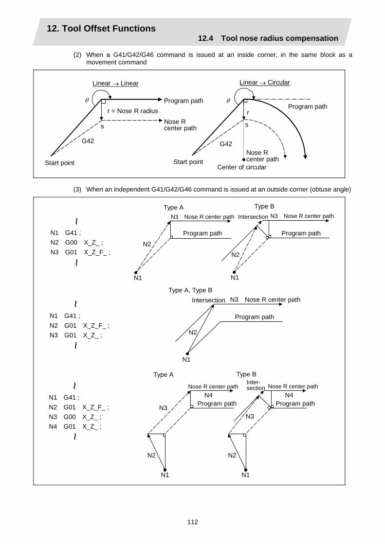
12. Tool Offset Functions 12.4 Tool nose radius compensation
112
(2) When a G41/G42/G46 command is issued at an inside corner, in the same block as a movement command
G42
s s
G42
θ θ
r
Center of circular
Program path
Linear → Linear Linear → Circular
Program path
Start point Start point
r = Nose R radius
Nose R center path
Nose R center path
(3) When an independent G41/G42/G46 command is issued at an outside corner (obtuse angle)
N1
N2
N1 G41 ; N2 G00 X_Z_ ; N3 G01 X_Z_F_ ;
N1 G41 ; N2 G01 X_Z_F_ ; N3 G01 X_Z_ ;
N1 G41 ; N2 G01 X_Z_F_ ; N3 G00 X_Z_ ; N4 G01 X_Z_ ;
N1
N2
N3
N4
N1
N2
N1
N2
N1
N2
N3
N4
~~
~~
~~
Type AN3 Nose R center path Intersection
Program path
Type B N3 Nose R center path
Program path
IntersectionType A, Type B
Program path
N3 Nose R center path
Inter-section
Type B
Nose R center path
Program path
Type A
Nose R center path
Program path

12. Tool Offset Functions 12.4 Tool nose radius compensation
113
N1 G41 ; N2 G00 X_Z_ ; N3 G00 X_Z_ ; N4 G01 X_Z_F_ ;
N3
N1
N2
N4
N3
N1
N2
N4
~~
Inter-section
Type BNose R center path
Program path
Type ANose R center path
Program path
(4) When a G41/G42/G46 command is issued at an outside corner (obtuse angle), in the same
block as a movement command [90° ≤ θ < 180°]
Linear → Linear (Type A)
G41
s
θ
Linear → Circular (Type A)
G41
r
s
θ
Linear → Circular (Type B)
G41
r r
s
θ
Linear → Linear (Type B)
G41
r r
s
θ
Start point Start point
r = Nose R radius
Program path
Nose R center path
Program path
Center of circular
Nose R center path
Start point Start point
Nose R center path
Program path
Intersection Intersection
Program path
Center of circular
Nose R center path

12. Tool Offset Functions 12.4 Tool nose radius compensation
114
(5) When an independent G41/G42/G46 command is issued at an outside corner (acute angle)
N1 G41 ; N2 G00 X_Z_ ; N3 G01 X_Z_F_ ;
N1 G41 ; N2 G01 X_Z_F_ ; N3 G01 X_Z_ ;
N1 G41 ; N2 G01 X_Z_F_ ; N3 G00 X_Z_ ; N4 G01 X_Z_ ;
N1 G41 ; N2 G00 X_Z_ ; N3 G00 X_Z_ ; N4 G01 X_Z_ F_ ;
N2
N2 N1 N1
N2
N1
N2
N1
N3
N2
N1
N3
N2
N1N3
N2
N1
N3
N3 N3
N3
~ ~
~ ~
~ ~
~ ~
Type BNose R center path
Program path
Type ANose R center path
Program path
Type A, Type B
Nose R center path
Program path
Type BNose R center path
Program path
Type ANose R center path
Program pathProgram path
Nose R center pathProgram path
Nose R center path
N4 N4
N4 N4
Type B
Nose R center path
Type A
Nose R center path
Program path
Program path
Nose R center path
Program path
Nose R center path Program
path

12. Tool Offset Functions 12.4 Tool nose radius compensation
115
(6) When a G41/G42/G46 command is issued at an outside corner (acute angle), in the same block as a movement command [ θ < 90° ]
G41
r
r
s
θ
Linear → Circular (Type B)
Linear → Linear (Type A)
G41
r
s
θ
Linear → Circular (Type A)
G41
r
s
θ
Linear → Linear (Type B)
G41
r
r
s
θ
Start point
Nose R center path
Program path
Start point
Program path
Nose R center path
Center of circular
Nose R center path
Program path
Start point
Start point
Program path
Nose R center path
Center of circular
(Note 1) Where is no axis movement command in the same block as G41 or G42, compensation is performed perpendicularly to the next block direction.

12. Tool Offset Functions 12.4 Tool nose radius compensation
116
Operations in compensation mode
The tool center path is obtained and compensated from the linear and arc designations for the program path (G00, G01, G02, G03). Compensation is valid both for positioning and for interpolation commands such as circular and linear interpolation. Even if the same compensation command (G41, G42, G46) is issued in a tool nose radius compensation (G41, G42, G46) mode, the command will be ignored. When 4 or more blocks not accompanying movement are commanded continuously in the compensation mode, overcutting or undercutting will result. When the M00 command has been issued during tool nose radius compensation, pre-reading is prohibited.
(1) Machining an outside corner
Linear → Linear (90° ≤ θ < 180°)
s
θ
Linear → Linear (0° < θ < 90°)
r
r
s θ
Intersection Nose R center path
Program path
Nose R center path
Program path
r
r θ
s
Linear → Circular (0° < θ < 90°)
s
r
θ
r
Linear → Circular (90° ≤ θ < 180°)
Nose R center path
Program path
Center of circular
Center of circular
Program path
Nose R center path
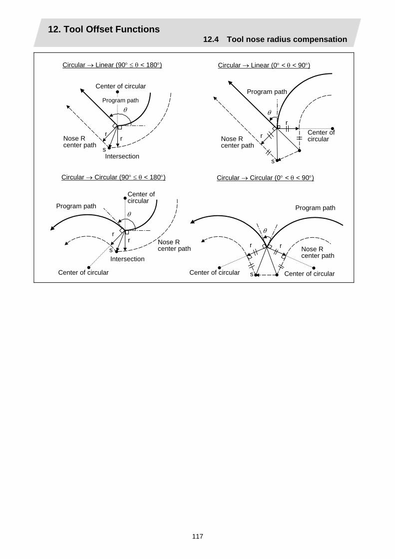
12. Tool Offset Functions 12.4 Tool nose radius compensation
117
Circular → Linear (0° < θ < 90°)
r
r
s
θ
Circular → Linear (90° ≤ θ < 180°)
r r
s
θ
Nose R center path
Program path
Center of circular Nose R
center path
Intersection
Program path
Center of circular
Circular → Circular (90° ≤ θ < 180°)
r r
s
θ
Circular → Circular (0° < θ < 90°)
r r
s
θ
Center of circular
Nose R center path
Program path
Center of circular
Center of circular
Program path
Center of circular
Nose R center pathIntersection
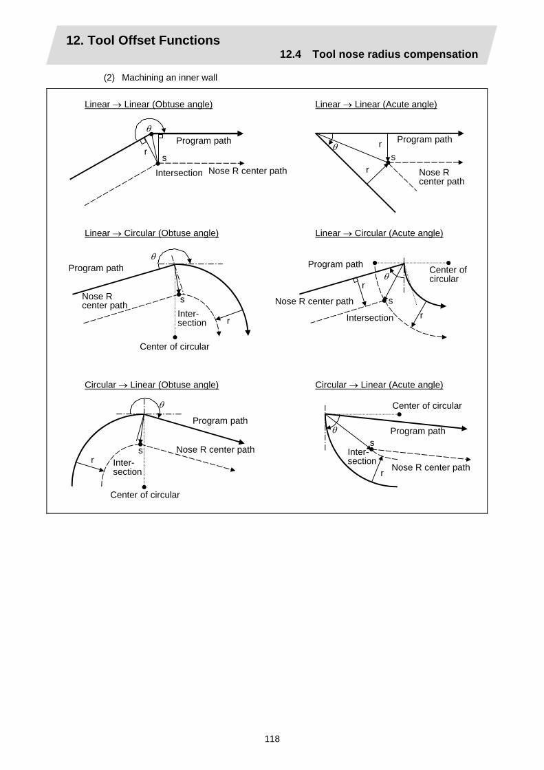
12. Tool Offset Functions 12.4 Tool nose radius compensation
118
(2) Machining an inner wall
Linear → Linear (Obtuse angle)
r s
θ
Linear → Linear (Acute angle)
r
r s
θ
r
Linear → Circular (Obtuse angle)
s
θ
r
r
Linear → Circular (Acute angle)
s
θ
r
Circular → Linear (Acute angle)
s θ
r
Circular → Linear (Obtuse angle)
θ
s
Program path
Nose R center path
Program path
Program pathProgram path
Program path
Nose R center pathIntersection
Program path
Nose R center path
Nose R center path
Center of circular
Nose R center path
Intersection
Center of circular
Nose R center pathInter- section
Center of circular
Center of circular
Inter-section
Inter- section

12. Tool Offset Functions 12.4 Tool nose radius compensation
119
Circular → Circular (Obtuse angle)
r
s
θ
Circular → Circular (Acute angle)
r
s
θ
Program path
Center of circular
Nose R center pathIntersection
Center of circular
Intersec-tion
Center of circular
Center of circular
Nose R center path
Program path
(3) When the arc end point is not on the arc
If the error applying after compensation is within the parameter (#1084 RadErr), the area from the arc start point to the end point is interpolated as a spiral arc.
r
r s
R
Nose R center path
End point of circularProgram path
Center of circular
Hypothetical circle
(4) When the inner intersection point does not exist
In an instance such as that shown in the figure below, the intersection point of circulars A and B may cease to exist due to the offset amount. In such cases, program error (P152) appears and the tool stops at the end point of the previous block.
r
r
A B
Nose R center path
Program error stop
Program path
Center of circular A
Line intersecting circulars A, B
12. Tool Offset Functions 12.4 Tool nose radius compensation
120
Tool nose radius compensation cancel
If either of the following conditions is met in the tool nose radius compensation mode, the compensation will be canceled. However, the movement command must be a command which is not a circular command. If the compensation is canceled by a circular command, program error (P151) results.
(1) The G40 command has been executed.
(2) The T00 tool number has been executed.
The cancel mode is established once the compensation cancel command has been read, 5-block pre-reading is suspended and 1-block pre-reading is applies instead.
Tool nose radius compensation cancel operation
Issuing a tool nose radius compensation cancel command results in the following.
(1) If the command before G40 is G00 after the tool nose radius compensation is completed, the tool nose radius compensation is temporarily stopped, and the tool nose radius compensation is canceled in that state by an independent G40 command.
(2) If there is an interpolation command before G40 after the tool nose radius compensation is completed, the tool nose radius compensation is not canceled by the independent G40 command, so the nose R center can stop in a vertical position. Instead, the tool nose radius compensation is canceled by the first axis movement command after G40. The nose radius compensation will not be canceled by the axis command if there is no axis movement. If there is no axis movement command after G40, and the program finishes by M02, etc., the tool nose radius compensation will remain valid. Resetting will cancel the tool nose radius compensation, but the operation will not be canceled.
(3) When an independent T00 command is issued in a block, a tool nose radius cancel mode will result in that block, and the axis will move to the tool nose radius cancel position.

12. Tool Offset Functions 12.4 Tool nose radius compensation
121
(4) Relation of an inside corner/outside corner and cancel (a)-1 When an independent G40 command is issued at an inside corner
N1 G01 X_Z_F_ ; N2 G00 X_Z_ ; N3 G40 ;
N1 G01 X_Z_F_ ; N2 G01 X_Z_ ; N3 G40 ; N4 M05 ; N5 G00 X_Z_ ;
N1 G01 X_Z_F_ ; N2 G00 X_Z_ ; N3 G01 X_Z_ ; N4 G40 ; N5 M05 ; N6 G01 X_Z_ ;
N1 G01 X_Z_F_ ; N2 G00 X_Z_ ; N3 G00 X_Z_ ; N4 G40 ;
N1N2
N3
N5
N2
N3N4
N1
N4N5
N2
N3
N1
N6
N2
N3
N1
N4
~~
~~
~~
~~
Nose R center path
Program path
Inter-section
Nose R center path
Program path
Nose R center path
Program path
Program path
Nose R center path

12. Tool Offset Functions 12.4 Tool nose radius compensation
122
(a)-2 When a G40 command is issued at an inside corner, in the same block as a movement command
Linear → Linear
s
θ
G40 G40
Circular → Linear
r
s
θ
End point
r = Nose R radius
Nose R center path
Program path
End point
Nose R center path
Program path
Center of circular

12. Tool Offset Functions 12.4 Tool nose radius compensation
123
(b)-1 When an independent G40 command is issued at an outside corner (obtuse angle)
N1 G01 X_Z_F_ ; N2 G00 X_Z_ ; N3 G40 ;
N1 G01 X_Z_F_ ; N2 G01 X_Z_ ; N3 G40 ; N4 M05 ; N5 G00 X_Z_ ;
N1 G01 X_Z_F_ ; N2 G00 X_Z_ ; N3 G01 X_Z_ ; N4 G40 ; N5 M05 ; N6 G01 X_Z_ ;
N1 G01 X_Z_F_ ; N2 G00 X_Z_ ; N3 G00 X_Z_ ; N4 G40 ;
N1
N3
N2
N2
N3N4
N5
N2
N4N5
N3
N6
N2
N4N5
N3
N6
N3
N2
N4
~~
~~
~~
~~
Nose R center path
Program path
Type A, Type B
Type A, Type BN1 Nose R center path
Program path Intersection
Type AN1 Nose R center path
Program pathType B
(Type B) N1 Nose R center path
Program path
N1 Nose R center path
Program path
Type A, Type B
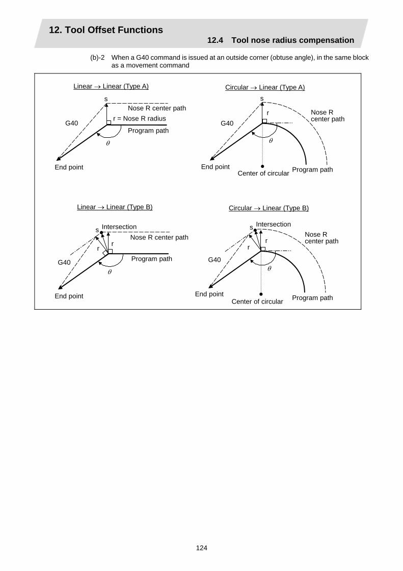
12. Tool Offset Functions 12.4 Tool nose radius compensation
124
(b)-2 When a G40 command is issued at an outside corner (obtuse angle), in the same block as a movement command
Center of circular
Linear → Linear (Type A)
s
θ
G40
Circular → Linear (Type A)
G40r
s
θ
r
s
θ G40
r
G40
r
s
θ
r
Linear → Linear (Type B) Circular → Linear (Type B)
End pointCenter of circular
Nose R center path
Program path
r = Nose R radius Nose R center path
Program path
Program path
Program path
Nose R center path
Nose R center path
End point
End point
Intersection Intersection
End point

12. Tool Offset Functions 12.4 Tool nose radius compensation
125
(c)-1 When an independent G40 command is issued at an outside corner (acute angle)
N1 G01 X_Z_F_ ; N2 G00 X_Z_ ; N3 G40 ;
N1 G01 X_Z_F_ ; N2 G01 X_Z_ ; N3 G40 ; N4 M05 ; N5 G00 X_Z_ ;
N1 G01 X_Z_F_ ; N2 G00 X_Z_ ; N3 G01 X_Z_ ; N4 G40 ; N5 M05 ; N6 G01 X_Z_ ;
N1 G01 X_Z_F_ ; N2 G00 X_Z_ ; N3 G00 X_Z_ ; N4 G40 ;
N3
N2
N3N4
N2N5
N2 N4
N4N5N2
N3
N6N4N5
N2N3
N6
N3
~~
~~
~~
~~
N1 Nose R center path
Program path
Type A, Type B
Type A, Type B
N1 Nose R center path
Program path
N1 Nose R center path
Program path
Type A Type B
N1 Nose R center path
Program path
Nose R center path
N1 Nose R center path
Program path
Type A, Type B
(Type A, Type B)

12. Tool Offset Functions 12.4 Tool nose radius compensation
126
(c)-2 When a G40 command is issued at an outside corner (acute angle), in the same block as a movement command
Nose R center path
End point
Program path
Linear Linear (type A)
r
s
θ
G40
Circular Linear (type A)
s
G40
r
θ
Nose R center path
Program path
End point
Center of circular
Linear Linear (type B)
r
s θ
G40
r
Nose R center path
End point
Program path
Circular Linear (type B)
r
sθ
G40
r
Nose R center path
Program path
Center of circular
End point
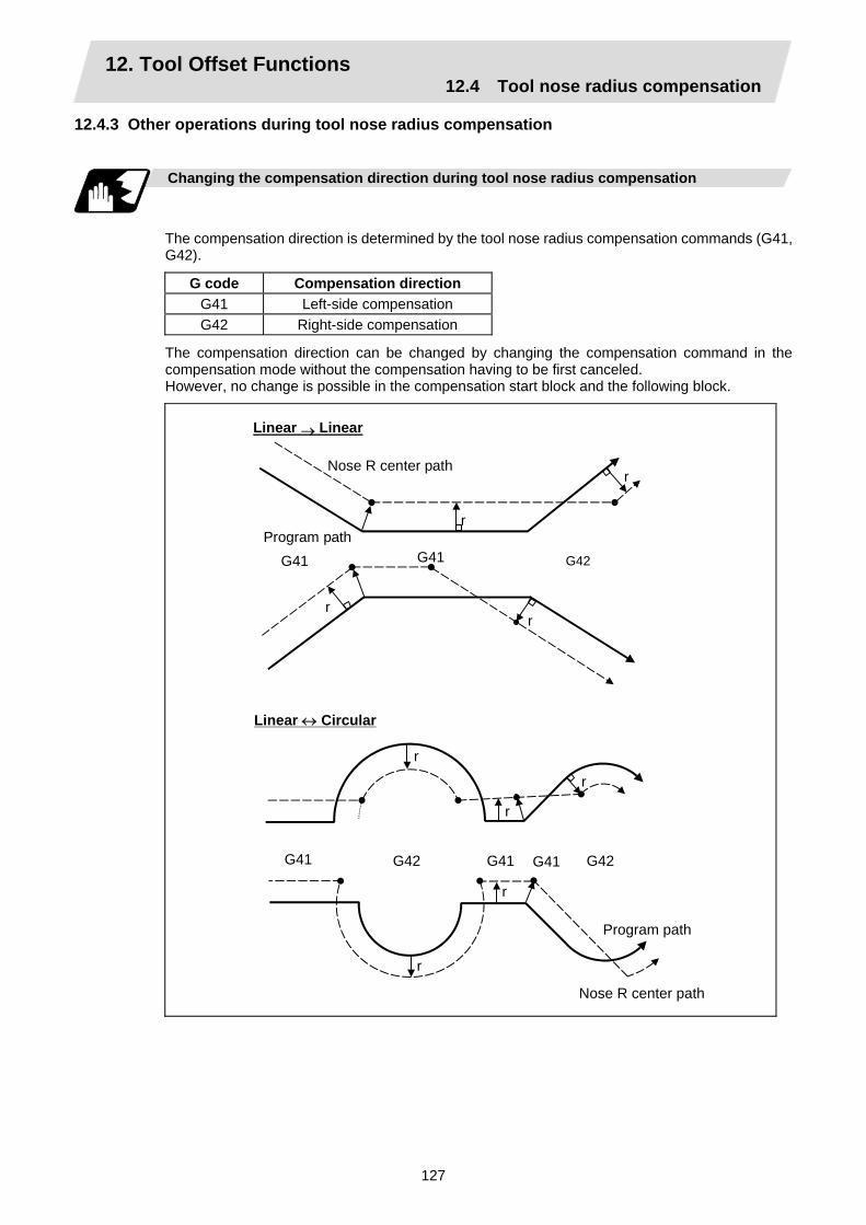
12. Tool Offset Functions 12.4 Tool nose radius compensation
127
12.4.3 Other operations during tool nose radius compensation
Changing the compensation direction during tool nose radius compensation
The compensation direction is determined by the tool nose radius compensation commands (G41, G42).
G code Compensation direction G41 Left-side compensation G42 Right-side compensation
The compensation direction can be changed by changing the compensation command in the compensation mode without the compensation having to be first canceled. However, no change is possible in the compensation start block and the following block.
r
G41
r
Linear → Linear
G41 G42
r
r
Nose R center path
Program path
Linear ↔ Circular
Nose R center path
G41
r
G41 G42 G41 G42
r
r
r
r
Program path

12. Tool Offset Functions 12.4 Tool nose radius compensation
128
Linear return
G41
G42 r Nose R center path
Program path
Arc exceeding 360° due to compensation method
G41
G42
G42
Program path
Nose R center path
Section left uncut
In the cases below, it is possible that the circular may exceed 360°. a. With offset direction selection
based on G41/G42 In cases like this, compensation is provided shown in the figure on the left and a section will be left uncut.
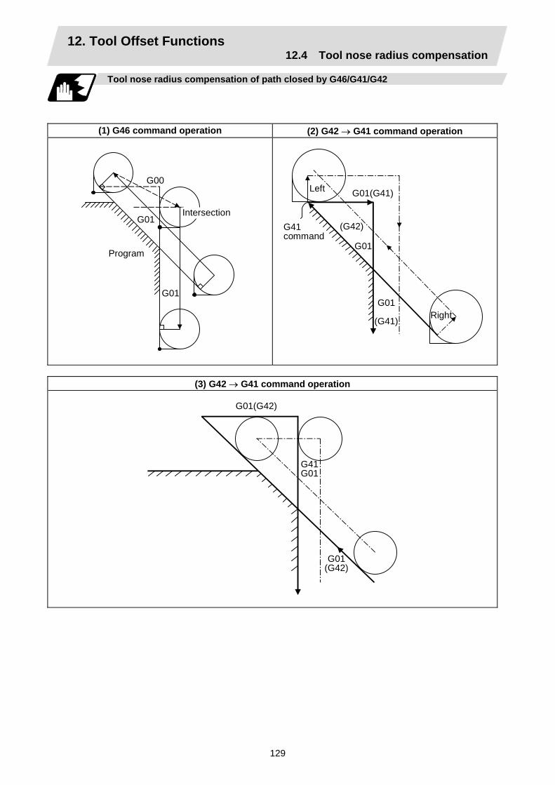
12. Tool Offset Functions 12.4 Tool nose radius compensation
129
Tool nose radius compensation of path closed by G46/G41/G42
(1) G46 command operation (2) G42 → G41 command operation
G00
G01
G01
Program
Intersection
G01(G41)
G01
(G41)
(G42)
G01
G41command
Left
Right
(3) G42 → G41 command operation
G01(G42)
G41G01
G01(G42)
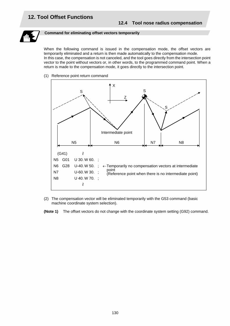
12. Tool Offset Functions 12.4 Tool nose radius compensation
130
Command for eliminating offset vectors temporarily
When the following command is issued in the compensation mode, the offset vectors are temporarily eliminated and a return is then made automatically to the compensation mode. In this case, the compensation is not canceled, and the tool goes directly from the intersection point vector to the point without vectors or, in other words, to the programmed command point. When a return is made to the compensation mode, it goes directly to the intersection point. (1) Reference point return command
X
ZS S
S
N5 N6 N7 N8
(G41) N5 G01 U 30. W 60. ; N6 G28 U-40. W 50. ; N7 U-60. W 30. ; N8 U 40. W 70. ;
~
Intermediate point
←Temporarily no compensation vectors at intermediate point (Reference point when there is no intermediate point)
~
(2) The compensation vector will be eliminated temporarily with the G53 command (basic
machine coordinate system selection).
(Note 1) The offset vectors do not change with the coordinate system setting (G92) command.

12. Tool Offset Functions 12.4 Tool nose radius compensation
131
(3) Positioning (G00) commands Tool nose radius compensation is temporarily canceled for G00 commands.
N3N2N1 N4 N5
N3
N2
N1 N4 N5
N3N2N1
N4N5
N1 G01 X_Z_F_ ; N2 G00 X_Z_ ; N3 G00 X_Z_ ; N4 G00 X_Z_ ; N5 G01 X_Z_ ;
N1 G01 X_Z_F_ ; N2 G01 X_Z_ ; N3 G01 X_Z_ ; N4 G00 X_Z_ ; N5 G01 X_Z_ ;
N1 G01 X_Z_F_ ; N2 G01 X_Z_ ; N3 G00 X_Z_ ; N4 G00 X_Z_ ; N5 G01 X_Z_ ;
~~
~~
~~
Nose R center path
Program path
Nose R center path
Program path
Nose R center path
Nose R center path
Nose R center path
Program path
Nose R center path
Program path
Program path
Program path
Intersection
Intersection
Intersection
(4) G33 thread cutting command
Tool nose radius compensation does not apply to the G33 block.
r
G33
Nose R center path
Program path
Intersection
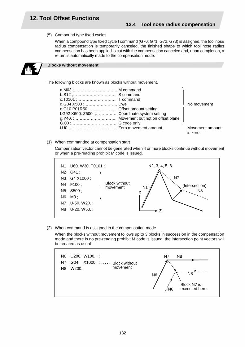
12. Tool Offset Functions 12.4 Tool nose radius compensation
132
(5) Compound type fixed cycles When a compound type fixed cycle I command (G70, G71, G72, G73) is assigned, the tool nose radius compensation is temporarily canceled, the finished shape to which tool nose radius compensation has been applied is cut with the compensation canceled and, upon completion, a return is automatically made to the compensation mode.
Blocks without movement
The following blocks are known as blocks without movement.
a.M03 ;…………………….…….b.S12 ;…………………………..c.T0101 ;………………………..d.G04 X500 ;……………………e.G10 P01R50 ;………………..f.G92 X600. Z500. ;……………g.Y40. ;………………………….G.00 ;……………………………i.U0 ;…………………………….
M command S command T command Dwell Offset amount setting Coordinate system setting Movement but not on offset plane G code only Zero movement amount
No movement Movement amount is zero
(1) When commanded at compensation start
Compensation vector cannot be generated when 4 or more blocks continue without movement or when a pre-reading prohibit M code is issued.
N1 U60. W30. T0101 ; N2 G41 ; N3 G4 X1000 ; N4 F100 ; N5 S500 ; N6 M3 ; N7 U-50. W20. ; N8 U-20. W50. ;
N1
N2, 3, 4, 5, 6
N7
N8X
Z
Block withoutmovement (Intersection)
(2) When command is assigned in the compensation mode When the blocks without movement follows up to 3 blocks in succession in the compensation mode and there is no pre-reading prohibit M code is issued, the intersection point vectors will be created as usual.
N6 U200. W100. ; N7 G04 X1000 ; ….. N8 W200. ; N8 N6
N7
N6
N8
Block N7 is executed here.
Block withoutmovement

12. Tool Offset Functions 12.4 Tool nose radius compensation
133
When 4 or more blocks without movement follow in succession or when a pre-reading prohibit M code is issued, the offset vectors are created perpendicularly at the end point of the previous block.
N6 U200. W100. ; N7 G4 X1000 ; N8 F100 ; N9 S500 ; N10 M4 ; N11 W100. ;
N11
N6N7~N10
N6
N11
In this case, a cut result
Block withoutmovement
(3) When commanded together with compensation cancel Only the offset vectors are canceled when a block without movement is commanded together with the G40 command.
N6 U200. W100. ; N7 G40 M5 ; N8 U50. W100. ;
N6
N7
N8
X
Z
When I, J, K are commanded in G40
A perpendicular vector is created in the block before G40.
r
G40
(i,k)
A
(a,b)
r G41
X
Z
Nose R center path
Program path
Hypothetical nose R center path

12. Tool Offset Functions 12.4 Tool nose radius compensation
134
Corner movement
When a multiple number of compensation vectors are created at the joints between movement command blocks, the tool will move in a linear between those vectors. This action is called corner movement. When the vectors do not coincide, the tool moves in order to machine the corner. Consequently, operation in the single block mode will execute the previous block + corner movement as a single block and the remaining joining movement + following block will be executed as a single block in the following operation.
r
N1
N2θ
r
Stop point with single block
Nose R center path
Program path
Center of circular
This movement and feedrate fall under block N2.

12. Tool Offset Functions 12.4 Tool nose radius compensation
135
12.4.4 G41/G42 commands and I, J, K designation
Function and purpose
The compensation direction can be intentionally changed by issuing the G41/G42 command and I, J, K in the same block.
Command format
G18 (Z-X plane) G41/G42 X Z I K ;
Assign a linear command (G00, G01) in a movement mode.
I, K type vectors (G18 X-Z plane selection)
The new I, K type vector (G18 plane) created by this command is now described. (Similar descriptions apply to vector I, J for the G17 plane and to J, K for the G19 plane.) As shown in the figures below, the vectors with a size equivalent to the offset amount are made to serve as the I, K type compensation vector perpendicularly to the direction designated by I, K without the intersection point of the programmed path being calculated. The I, K vector can be commanded even in the mode (G41/G42 mode in the block before) and even at the compensation start (G40 mode in the block before). (1) When I, K is commanded at compensation start
N150
N100
X
Z
N110 N120 N130 N140
T0101
Program pathNose R center path
(G40) N100 G41 U100. W100. K150. T0101 ;N110 G04 X1000 ; N120 G01 F1000 ; N130 S500 ; N140 M03 ; N150 Z150. ;
~ ~
(2) When there are no movement commands at the compensation start
(G40) N1 G41 K150. T0101 ; N2 U100. W100. ; N3 W150. ;
~N3
N2
X
Z
T0101 N1
~

12. Tool Offset Functions 12.4 Tool nose radius compensation
136
(3) When I, K has been commanded in the mode (G18 plane)
X Z
~
(G18 G41) N100 G41 T0101 G01 W150. I50. ; N110 G02 W100. I50. ; N120 G01 W100. ~
(1) I, K type vector (2) Intersection point calculation type vector
Program path Nose R center path Path for intersection point calculation
N100
(I,K)N110
(N120)T0101
(2)
(1)
(4) When I, K has been commanded in a block without movement
N1T0101
N2
N3 N4
N5(I,K) N1 G41 T0101 G01 F1000 ; N2 U100. W100. ; N3 G41 K50. ; N4 W150. ; N5 G40 ;
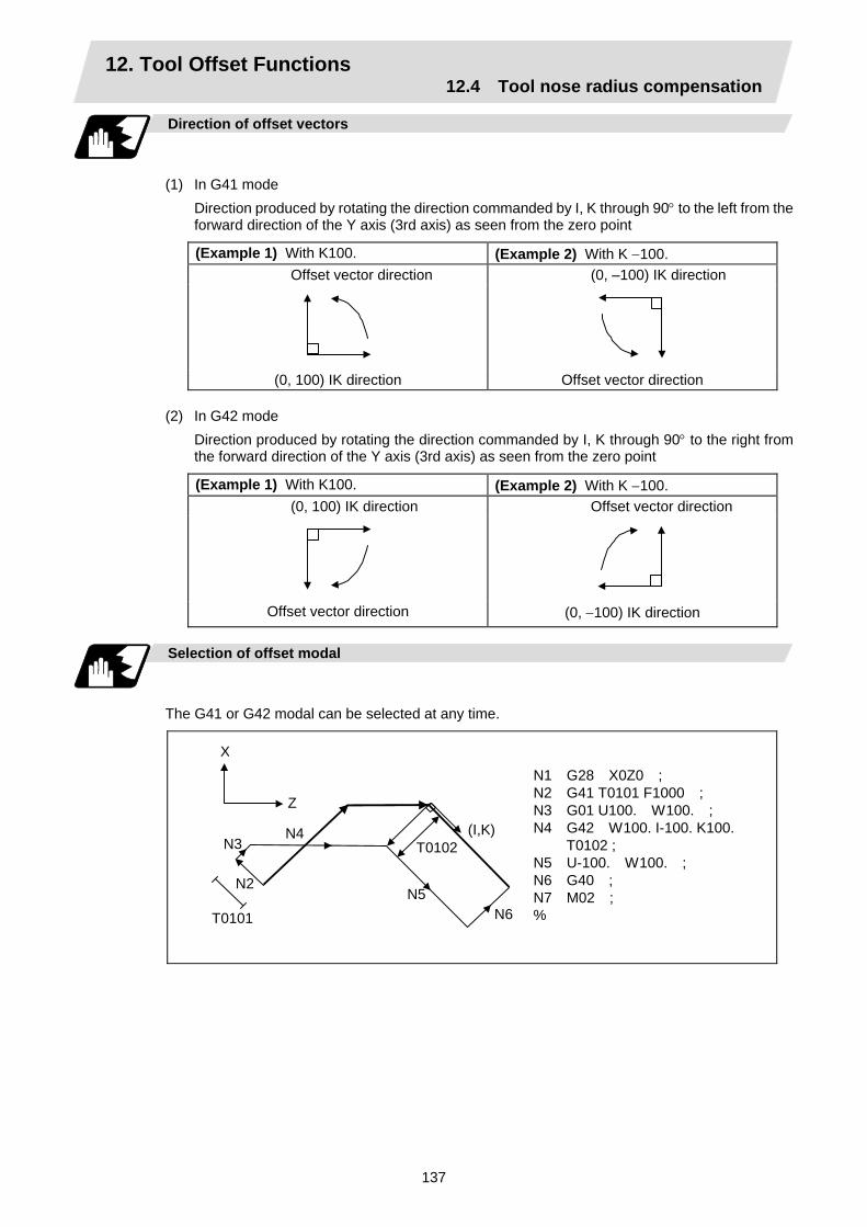
12. Tool Offset Functions 12.4 Tool nose radius compensation
137
Direction of offset vectors
(1) In G41 mode
Direction produced by rotating the direction commanded by I, K through 90° to the left from the forward direction of the Y axis (3rd axis) as seen from the zero point
(Example 1) With K100. (Example 2) With K −100. Offset vector direction (0, –100) IK direction
(0, 100) IK direction Offset vector direction
(2) In G42 mode Direction produced by rotating the direction commanded by I, K through 90° to the right from the forward direction of the Y axis (3rd axis) as seen from the zero point
(Example 1) With K100. (Example 2) With K −100. (0, 100) IK direction Offset vector direction
Offset vector direction (0, −100) IK direction
Selection of offset modal
The G41 or G42 modal can be selected at any time.
N1 G28 X0Z0 ; N2 G41 T0101 F1000 ; N3 G01 U100. W100. ; N4 G42 W100. I-100. K100.
T0102 ; N5 U-100. W100. ; N6 G40 ; N7 M02 ; %
N3
Z
T0101
N2
N6
(I,K)
N5
X
N4 T0102

12. Tool Offset Functions 12.4 Tool nose radius compensation
138
Offset amount for offset vectors
The offset amounts are determined by the offset number (modal) in the block with the I, K designation.
(G41 T0101) N100 G41 W150. K50. ;N110 U-100. W100. ;
Z N110
(I,K) (A)
X N100
T0101T0101 ~
~<Example 1>
Vector (A) is the offset amount entered in tool offset number modal 1 in the N100 block.
(G41 T0101) N200 G41 W150. K50. T0102 ;N210 U-100. W100. ;
Z N210
(I,K)
(B)
X N200
T0102 T0101
~~
<Example 2>
Vector (B) is the offset amount entered in tool offset number modal 2 in the N200 block.

12. Tool Offset Functions 12.4 Tool nose radius compensation
139
Precautions
(1) Issue the I, K type vector in a linear mode (G0, G1). If it is issued in an arc mode at the start of compensation, program error (P151 G2, 3 CMP. ERR) will result.
An I, K designation in an arc mode functions as an arc center designation in the offset mode.
(2) When the I, K type vector has been designated, it is not deleted (avoidance of interference) even if there is interference. Consequently, overcutting may arise in such a case.
Cut
N1 G28 X0Z0 ; N2 G41 T0101 F1000 ; N3 W100. ; N4 G41 U-100. W100. K10. ;N5 U100. W100. ; N6 G40 ; N7 M02 ;
N3 N4 N5 N6
(I,K)
X
Z
(3) Refer to the following table for the offset methods based on the presence and/or absence of the G41 and G42 commands and I, K (J) command.
G41/G42 I, K (J) Offset method No No Intersection point calculation type vector No Yes Intersection point calculation type vector Yes No Intersection point calculation type vector Yes Yes I, K type vector No insertion block

12. Tool Offset Functions 12.4 Tool nose radius compensation
140
12.4.5 Interrupts during tool nose radius compensation
MDI interrupt
Tool nose radius compensation is valid in any automatic operation mode - whether memory or MDI operation. An interrupt based on MDI will give the result as in the figure blow after block stop during memory operation. (1) Interrupt without movement (tool path does not change)
X
Z
N1 G41 T0101 ;
N2 U50. W20. ;
N3 G3 U−40. W40. R70. ; S1000 M3 ;
MDI interrupt
N2 N3
(Stop position with single block)S
(2) Interrupt with movement The offset vectors are automatically re-calculated at the movement block after interrupt.
S
S
N2N3
MDI interrupt
With linear interrupt N1 G41 T0101 ;
N2 U50. W20. ;
N3 G3 U−40. W40. R70. ; U−30. W50. ;
U50. W30. ;
S
S
N2 N3
With circular interrupt
N1 G41 T0101 ;
N2 U50. W20. ;
N3 G3 U−40. W40. R70. ; G2 U−40. W40. R70. ;
G1 W40. ;
MDI interrupt

12. Tool Offset Functions 12.4 Tool nose radius compensation
141
Manual interrupt
(1) Interrupt with manual
absolute OFF. The tool path is shifted by an amount equivalent to the interrupt amount.
Interrupt
Program path
Tool path after compensation
Tool path after interrupt
(2) Interrupt with manual absolute ON. In the incremental value mode, the same operation results as with manual absolute OFF. In the absolute value mode, however, the tool returns to its original path at the end point of the block following the interrupted block, as shown in the figure.
Interrupt
Interrupt

12. Tool Offset Functions 12.4 Tool nose radius compensation
142
12.4.6 General precautions for tool nose radius compensation
Assigning the compensation amounts
(1) The compensation amount is normally assigned by designating the number of the
compensation amount by the last 1 or 2 digits of the T code. Depending on the machine specifications, the high-order digits may be used. The T code will remain valid once designated until another T code is subsequently commanded.
Besides being used to designate the compensation amounts for tool nose radius compensation, the T codes are also used to designate the offset amounts for tool length offset.
(2) The compensation amounts are normally changed when a different tool has been selected in the compensation cancel mode. However, when an amount is changed in the compensation mode, the vectors at the end point of the block are calculated using the compensation amount designated in that block.
Errors during tool nose radius compensation
(1) An error results when any of the following commands are programmed during tool nose radius
compensation.
G17, G18, G19 ("P112" when a plane differing from that applying during the compensation has been commanded) G31 ("P608") G74, G75, G76 ("P155") G81 ~ G89 ("P155")
(2) An error ("P158") results when a tool nose point other than 1 to 8 has been designated in the G46 mode.
(3) An error ("P156") results when the compensation direction is not determined by the movement vector of the initial cutting command even when the tool nose radius compensation operation has started in the G46 mode and 5 blocks have been pre-read.
(4) An error ("P151") results when a circular command is issued in the first or last block of the tool nose radius compensation.
(5) A program error ("P157") results when the offset direction is reversed in the G46 mode. A parameter can be set to move the tool in the same compensation direction. (Control parameter "#8106 G46 NO REV-ERR")
(6) A program error ("P152") results during tool nose radius compensation when the intersection point is not determined with single block skip in the interference block processing.
(7) A program error results when there is an error in one of the pre-read blocks during tool nose radius compensation.
(8) A program error ("P153") results when interference arises under no interference avoidance conditions during tool nose radius compensation.
(9) A program error ("P150") results when a tool nose radius compensation command is issued even though the tool nose radius compensation specification has not been provided.
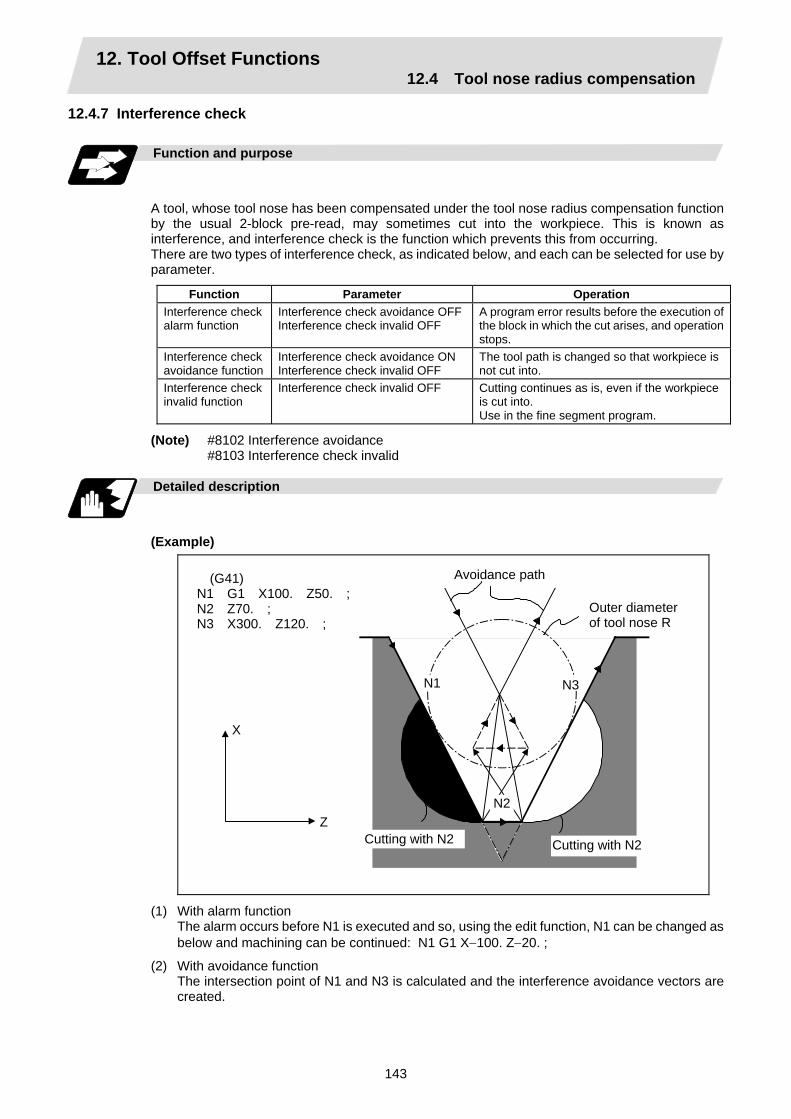
12. Tool Offset Functions 12.4 Tool nose radius compensation
143
12.4.7 Interference check
Function and purpose
A tool, whose tool nose has been compensated under the tool nose radius compensation function by the usual 2-block pre-read, may sometimes cut into the workpiece. This is known as interference, and interference check is the function which prevents this from occurring. There are two types of interference check, as indicated below, and each can be selected for use by parameter.
Function Parameter Operation Interference check alarm function
Interference check avoidance OFFInterference check invalid OFF
A program error results before the execution of the block in which the cut arises, and operation stops.
Interference check avoidance function
Interference check avoidance ON Interference check invalid OFF
The tool path is changed so that workpiece is not cut into.
Interference check invalid function
Interference check invalid OFF Cutting continues as is, even if the workpiece is cut into. Use in the fine segment program.
(Note) #8102 Interference avoidance #8103 Interference check invalid
Detailed description
(Example)
Avoidance path
Outer diameter of tool nose R
(G41) N1 G1 X100. Z50. ; N2 Z70. ; N3 X300. Z120. ;
N1 N3
N2
X
Z
Cutting with N2 Cutting with N2
(1) With alarm function The alarm occurs before N1 is executed and so, using the edit function, N1 can be changed as
below and machining can be continued: N1 G1 X−100. Z−20. ;
(2) With avoidance function The intersection point of N1 and N3 is calculated and the interference avoidance vectors are
created.

12. Tool Offset Functions 12.4 Tool nose radius compensation
144
(3) With interference check invalid function The tool passes while cutting into the straight line between N1 and N3.
(a) Conditions regarded as interference If there is a movement command in three of the five pre-read blocks, and if the compensation calculation vectors created at the contacts of each movement command intersect, it will be regarded as an interference.
Nose R center path Program path
Vectors intersect N1 N3
N2
r
(b) When interference check cannot be executed (i) When three of the movement command blocks cannot be pre-read
(When there are three or more blocks in the five pre-read blocks that do not have movement)
(ii) When there is an interference following the fourth movement block
Nose R center path
Program path
Interference check is not possible
N1
N3
N2
N4
N5
N6

12. Tool Offset Functions 12.4 Tool nose radius compensation
145
Operation during interference avoidance
The movement will be as shown below when the interference avoidance check is used.
Nose R center path Program path
N1 N3
N2
Nose R center path when interference is avoided
Nose R center path without interference check
Nose R center path when interference is avoided
Program pathNose R center path without interference check
N2
N1
N3
Solid line : Path when interference is avoided. Broken line: Path when interference check is invalid.
Linear movement
Center of circular N1
N3 N2
r
r
Program path
In the case of the figure below, the groove will be left uncut.
Interference avoidance path
Nose R center path
Program path
Solid line : Path when interference is avoided. Broken line: Path when interference check is invalid.

12. Tool Offset Functions 12.4 Tool nose radius compensation
146
Interference check alarm
The interference check alarm occurs under the following conditions.
(1) When the interference check alarm function has been selected (a) When all the vectors at the end block of its own block have been deleted
When, as shown in the figure on the right, vectors 1 to 4 at the end point of the N1 block have all been deleted, program error (P153) results prior to N1 execution.
N1
2 3 N2
1
N34
(2) When the interference check avoidance function has been selected
(a) When there are valid vectors at the end point of the following block even when all the vectors at the end point of its own block have been deleted
(i) When, in the figure on the right, the N2 in interference check is conducted, the N2 end point vectors are all deleted but the N3 end point vectors are regarded as valid. Program error (P153) now occurs at the N1 end point.
Alarm stop
N1 2
N2
1
N3
4
3
N4
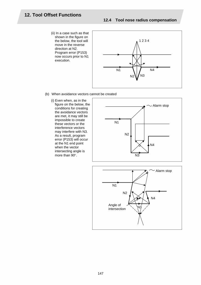
12. Tool Offset Functions 12.4 Tool nose radius compensation
147
(ii) In a case such as that
shown in the figure on the below, the tool will move in the reverse direction at N2. Program error (P153) now occurs prior to N1 execution.
N1
N2 N3
N4
1 2 3 4
(b) When avoidance vectors cannot be created
(i) Even when, as in the figure on the below, the conditions for creating the avoidance vectors are met, it may still be impossible to create these vectors or the interference vectors may interfere with N3. As a result, program error (P153) will occur at the N1 end point when the vector intersecting angle is more than 90°.
N1
N2
N3
N4
Alarm stop
Alarm stop
N1
N2
N3
N4
Angle of intersection
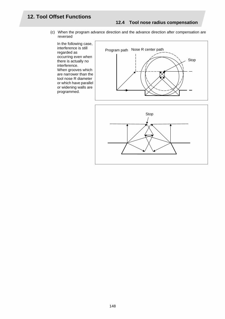
12. Tool Offset Functions 12.4 Tool nose radius compensation
148
(c) When the program advance direction and the advance direction after compensation are reversed
In the following case, interference is still regarded as occurring even when there is actually no interference. When grooves which are narrower than the tool nose R diameter or which have parallel or widening walls are programmed.
Program path Nose R center path
Stop
Stop

12. Tool Offset Functions 12.5 Programmed offset input
149
12.5 Programmed offset input; G10
Function and purpose
The amount of tool offset and workpiece offset can be set or changed by the G10 command. When commanded with absolute values (X,Z,R), the commanded offset amounts serve as the new amounts; when commanded with incremental values (U,W,C), the new offset amounts are equivalent to the commanded amounts plus the current offset amount settings.
Command format
(1) Workpiece offset input (L2)
G10 L2 P X (U )Z (W ) ; P X U Z W
Offset number X-axis offset amount (absolute) X-axis offset amount (incremental) Z-axis offset amount (absolute) Z-axis offset amount (incremental)
(2) Tool length offset input (L10)
G10 L10 P X (U )Z (W )R (C )Q ; P X U Z W R C Q
Offset number X-axis offset amount (absolute) X-axis offset amount (incremental) Z-axis offset amount (absolute) Z-axis offset amount (incremental) Tool nose radius compensation amount (absolute) Tool nose radius compensation amount (incremental) Hypothetical tool nose point
(3) Tool nose wear offset input (L11)
G10 L11 P X (U )Z (W )R (C )Q ; P X U Z W R C Q
Offset number X-axis offset amount (absolute) X-axis offset amount (incremental) Z-axis offset amount (absolute) Z-axis offset amount (incremental) Tool nose radius compensation amount (absolute) Tool nose radius compensation amount (incremental) Hypothetical tool nose point
(4) When there is no L command with tool length offset input (L10) or tool nose wear offset input
(L11) Tool length offset input command : P = 10000 + offset number Tool nose wear offset input command : P = offset number
(5) Offset input cancel
G11 ;

12. Tool Offset Functions 12.5 Programmed offset input
150
Detailed description
(1) The following table shows the offset numbers and the setting ranges of the hypothetical tool
nose points.
Setting range Address
Significance of address L2 L10 L11
P Offset number
0:External workpiece offset
1:G54 workpiece offset2:G55 workpiece offset3:G56 workpiece offset4:G57 workpiece offset5:G58 workpiece offset6:G59 workpiece offset
When L command is present:
1 to Max. number of offset sets
When L command is not present:
10001 to 10000 + Max. number of offset
When L command is/is not present:
1 to Max. number of offset sets
Q Hypothetical tool nose point
— 0 to 9
(Note1) The maximum number of offset sets for P (offset number) with tool offset input (L10 or L11) is up to a total of 80 with the addition of options.
(The No. of sets will differ according to the model so check the specifications.) (2) The setting range for the offset amount is given blow.
Program error (P35) occurs for any value not listed in the table after command unit conversion. With an incremental value command, the setting range for the offset amount is the sum of the present setting and command value.
Tool length offset amount Tool wear offset amount Input unit Metric system Inch system Metric system Inch system
IS - B ±99999.999 (mm) ±9999.9999 (inch) ±99999.999 (mm) ±9999.9999 (inch)IS - C ±9999.9999 (mm) ±999.99999 (inch) ±999.9999 (mm) ±999.99999 (inch)
12. Tool Offset Functions 12.5 Programmed offset input
151
Precautions and Restrictions
(1) Offset amount setting range check
The maximum value of the wear offset amount and the maximum additional value for the wear offset input check respectively take precedence for a single-time offset amount in the maximum value and incremental value command of the wear offset amount, and when an amount greater than these values has been commanded, program error (P35) results.
(2) G10 is an unmodal command and is valid only in the commanded block.
(3) Offset input can be performed similarly for the third axis but even when the C axis has been designated as the third axis, address C is treated as an incremental command value of the tool nose radius in the L10 or L11 command.
(4) If an illegal L number or tool compensation No. is commanded, program error (P172 or P170) will result, respectably.
(5) When the P command in the workpiece offset input is a command besides 0 to 6, or the P command is omitted, it will be handled as the currently selected workpiece offset input.
(6) Program error (P35) results when the offset amount exceeds the setting range.
(7) The offset amounts for the external workpiece coordinate system and the workpiece coordinate system are commanded as distances from the basic machine coordinate system zero point.
(8) X, Z and U, W are input together in a single block but when an address that commands the same offset input (X, U or Z, W) is commanded, the address which is input last is valid.
(9) Offset will be input if even one address following G10 L(2/10/11) P_ is commanded. Program error (P33) results when not even a single command has been assigned.
(Example) G10 L10 P3 Z50. ;
↓
(10) Decimal points are valid for offset amounts.
(11) G40 to G42 are ignored when they have been commanded in the same block as G10.
(12) Do not command G10 in the same block as fixed cycles and subprogram call commands. This will cause malfunctioning and program errors.
(13) When a T command has been issued in the same block as G10 with parameter "#1100 Tmove" as "0", the offset will be accomplished in the following block.
[Tool length data] # Z 3 50.000 Input as per left
12. Tool Offset Functions 12.6 Tool life management II
152
12.6 Tool life management II
Function and purpose
Tool life management divides the tools being used into several groups, and manages the life (usage time, No. of uses) of the tools in each group. When the life is reached, a similar spare tool in the same group will be selected in order. This tool life management function with spare tools allows unmanned operation over a long time. (1) Number of life-managed tools 1 part system : Maximum 80 tools,
2/3 part systems : Maximum 40 tools/part system (2) Number of groups 1 part system : Maximum 80 groups,
2/3 part systems : Maximum 40 groups/part system (3) Group No. 1 to 9999 (4) Number of tools in one group Maximum 16 tools (5) Life time 0 to 999999 minutes (approx. 16667 hours) (6) Number of lives 0 to 999999 times The tool life management data can be set from the NC program or from the Tool Life Management screen. Refer to the Operation manual for the method of setting from the Tool Life Management screen. When using the NC program, register the data with the same method as program compensation input.
Command format
G10 L3 ; P_ L_ N_ ;T_ ; T_ ;
Life management data registration start Registration of group No., life per tool, method Registration of tool No.;
First group
P_ L_ N_ ;T_ ; T_ ;
Registration of next group No., life per tool, method Registration of tool No.;
Next group
G11 ; End of life management data registration
P L N T
Group No., (1 to 9999) Life per tool (0 to 999999 minutes, or 0 to 999999 times) Method (0:Time management, 1:No. of times management) Tool No.; the spare tool is selected in the order registered here. (Tool number 1 to 999999. Compensation No. 1 to 80) "T_" (number of tools) follows the specifications.

12. Tool Offset Functions 12.6 Tool life management II
153
Precautions and restrictions
(1) The tool life data is registered by executing the above program in the memory or MDI mode.
(2) When the above program is executed, all data (group No., tool No., life data) registered previously will be deleted. The registered data is held even when the power is turned OFF.
(3) The group No. designated with P does not have to be consecutive, but it should be set in ascending order if possible. This will make monitoring on the screen easier. The group No. cannot be commanded in duplicate.
(4) If the life data L_ is omitted, the life data for that group will be "0". If N_, which designates the method, is omitted, the method for that group will follow the base specification parameter "#1106 Tcount".
(5) Programming with a sequence No. is not possible between G10 L3 and G11.
(6) If the usage data count valid signal (Y78A/Y86A/Y94A) is ON, G10 L3 cannot be commanded. (P177 LIFE COUNT ACT)
Example of program
(1) Format
: T 99 ;
Start use of group tool
: :
T 88 ; : :
Cancel group tool offset (Equivalent to T∆∆00: ∆∆is number of tool being used).
M02 (M30) ; End of machining program
(2) Actual example : T0119 ;
Start use of group 01 tool
: :
T0188 ; : :
Cancel group 01 tool offset If the number of the tool being used is 17, this is equivalent to T1700.
T0609 ; : :
Selects tool No. 06 and offset No. 09. * Life management is not carried out for tool 06.
T0600 ; : :
Cancel of group 06 tool offset
T0299 ; : :
Start use of group 02 tool
T0199 ; :
Start use of group 01 tool If the selected tool has several compensation numbers, the second compensation No. is selected.

12. Tool Offset Functions 12.6 Tool life management II
154
Example of tool selection operation (When one tool has several compensation numbers)
(1) To use several compensation numbers with one tool, select the next compensation No. for each T 99 command.
(2) If T 99 is commanded for more times than the number of registered compensation numbers, the last compensation No. will be selected, and the operation will continue. (Refer to following.)
Registration to group 1 Program Tool selection
T1701 T0199 ; Equivalent to T1701 :
T1702 T0199 ; Equivalent to T1702 :
T1703 T0199 ; Equivalent to T1703 :
T2104 T0199 ; Equivalent to T1703 : :
(Group 1) : :(Hereafter, same until tool 17 reaches life.)
(3) If the above program is executed after resetting with M02/M30, or by resetting with external reset, the selection will be made from the head compensation No.

12. Tool Offset Functions 12.6 Tool life management II
155
12.6.1 Counting the tool life
Function and purpose
The tool life can be counted with the time-count type or No. of uses-count type. The count method and timing for the No. of uses-count type can be changed to type 2 with the parameter setting (#1277 ext13/bit0). If the usage data is equivalent to or more than the life data as a result of the count up, a spare tool in the group will be selected with the next group selection command (T 99), and the newly selected tool will be counted. When all tools in the group have reached their lives and a spare tool cannot be selected, the count will continue.
(1) Counting the time of uses when the time-count type method is selected
In the cutting mode (G01, G02, G03, G31, G33, etc.), the time that the tool is used is counted with 100ms units. The time is not counted during dwell, machine lock, miscellaneous function lock or dry run. Whether to count or not for a single block can be changed by setting the parameter.
(Note) • The maximum value for the life is 999999 minutes.
• The data is displayed as a minute unit on the Tool Life Management screen.

12. Tool Offset Functions 12.6 Tool life management II
156
(2) Counting the No. of uses when the No. of uses-count type method is selected (a) Type 1 (#1277 ext13/bit0: 0)
The No. of uses is counted when the number of the tool being used is changed with the tool selection command (T 99) and when the program is in the cutting mode (excluding machine lock, miscellaneous function lock and dry run states). The use is not counted if the cutting mode is not entered even once after the No. changes. Whether to count or not during single block can be changed with the parameter setting.
(Note) • The maximum value for the life is 999999 times. • If only the compensation No. of the tool being used changes, a count will not be
made.
Example: When T code of tool being used is T12345678
T 1 2 3 4 5 6 7 8 Compensation No.: No count even when changed.Tool No.: Counted when changed.
<<Operation example>>
Program
Program
T0199....... 1 : T0199 : T0199
T0199........ 1 : T0299 : T0199........ 2 : T0299 : T0199........ 3
Group 01 has been used one time.
Group 01 has been used three times.
* The No. of uses is for one program execution. If the program is executed again after resetting, it will be counted.
(b) Type 2 (#1277 ext13/bit0: 1)
(i) Only the group used for cutting from when the machining program starts to when it is reset is incremented by "1". The count is made at the reset.
(ii) If recount M is commanded, the group used up to that point will be incremented by "1" in the counter.
(Note 1) A count is not made in the machine lock, miscellaneous function lock or dry
run states.
(Note 2) During single block, select whether to count with the parameter.
(Note 3) The maximum value of the life is 999999 times.

13. Program Support Functions 13.1 Fixed cycles for turning
157
13. Program Support Functions
13.1 Fixed cycles for turning
Function and purpose
When performing rough cutting and other such operations during turning, these functions enable shapes normally commanded in several blocks to be commanded in a single block. In other words, they simplify the machining program. The following types of fixed cycles for turning are available.
G code Function G77 Longitudinal turning cycle G78 Thread cutting cycle G79 Face turning cycle
Command format
G77 X/U_ Z/W_ R_ F_ ;
(Same for G78, G79)
Detailed description
(1) Fixed cycle commands are modal G codes and so they are valid until another command in the
same modal group or a cancel command is issued. The following G code cancel commands are available.
G00, G01, G02, G03 G07, G09, G10, G11, G27, G28, G29, G30, G31, G33, G34, G37, G92, G52, G53, G65,
(2) The fixed cycle call becomes the movement command block call. The movement command block call calls the fixed cycle macro subprogram only when there is an axis movement command during the fixed cycle mode. It is executed until the fixed cycle is canceled.
(3) A manual interrupt can be applied while a fixed cycle for turning (G77 ~ G79) is being executed.
Upon completion of the interrupt, however, the tool must be returned to the position where the manual interrupt was applied and then the fixed cycle for turning should be resumed. If it is resumed without the tool having been returned, all subsequent operations will deviate by an amount equivalent to the manual interrupt.

13. Program Support Functions 13.1 Fixed cycles for turning
158
13.1.1 Longitudinal cutting cycle; G77
Straight cutting
This function enables continuous straight cutting in the longitudinal direction using the following command.
G77 X/U_ Z/W_ F_ ;
X axis
Z axis
XZ W
U2
(R) : Rapid traverse(F) : Cutting feed 3(F) 2(F)
4(R)
1(R)
Taper cutting
This function enables continuous taper cutting in the longitudinal direction using the following command.
G77 X/U_ Z/W_ R_ F_ ;
X axis
Z axis
X Z W
3(F)2(F)
4(R)
1(R)
R
U 2
(R) : Rapid traverse(F) : Cutting feed
R: Taper depth (radius designation, incremental value, sign required)
With a single block, the tool stops at the end points of operations 1, 2, 3 and 4.

13. Program Support Functions 13.1 Fixed cycles for turning
159
Depending on the U, W and R signs, the following shapes are created.
(1) U < 0, W < 0, R < 0 (2) U < 0, W < 0, R > 0
W
R
X
Z
U 2 1
2
3
4
W
R
X
Z
U 2
1
2 3
4
(3) U > 0, W < 0, R < 0 (4) U > 0, W < 0, R > 0
W
R
X Z
U 2
1
2 3
4
W
R
X
Z
U 2 1
2
3
4
Program error (P191) results with shapes (2) and (3) unless the following condition is satisfied.
|u/2 | ≥ | r |
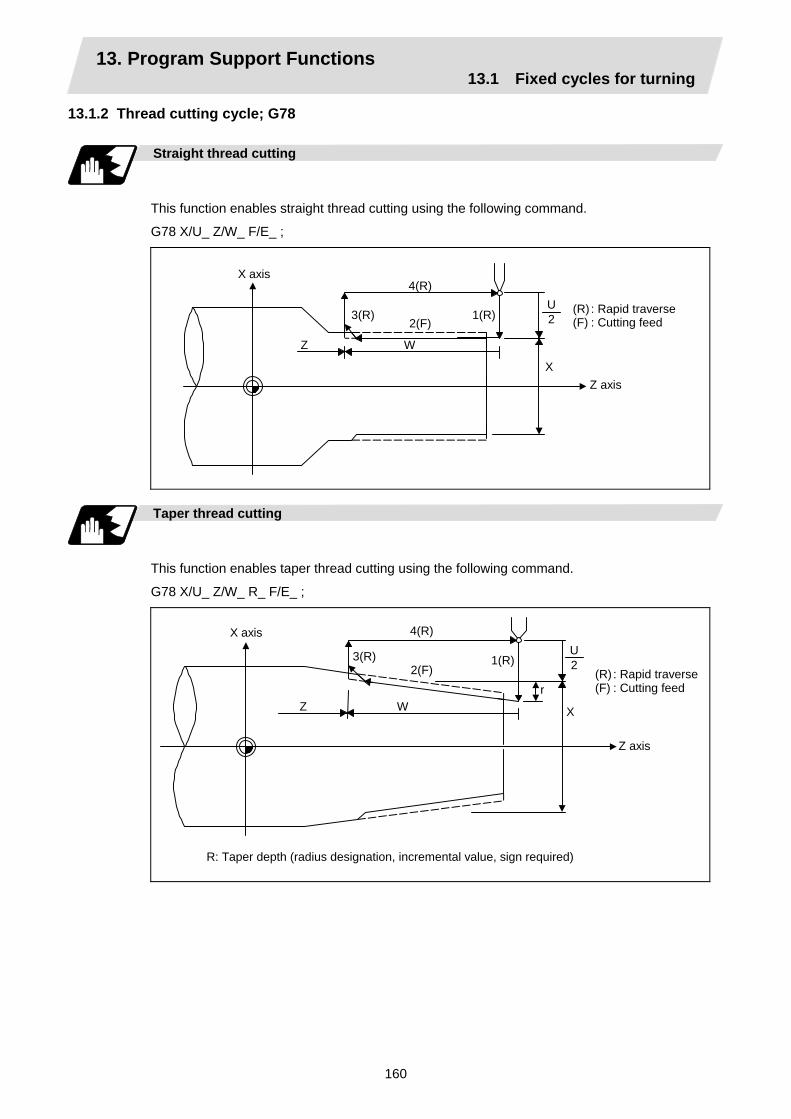
13. Program Support Functions 13.1 Fixed cycles for turning
160
13.1.2 Thread cutting cycle; G78
Straight thread cutting
This function enables straight thread cutting using the following command.
G78 X/U_ Z/W_ F/E_ ;
X axis
Z axis X
Z W
3(R)2(F)
4(R)
1(R)U2
(R) : Rapid traverse(F) : Cutting feed
Taper thread cutting
This function enables taper thread cutting using the following command.
G78 X/U_ Z/W_ R_ F/E_ ;
X axis
Z axis
X Z W
3(R)2(F)
4(R)
1(R)
r
U 2
(R) : Rapid traverse(F) : Cutting feed
R: Taper depth (radius designation, incremental value, sign required)

13. Program Support Functions 13.1 Fixed cycles for turning
161
Details for chamfering
α
θ
α : Chamfering amount of thread If the thread lead is assumed to be L,
then the parameter can be set in 0.1L units from 0 to 12.7L.
θ : Chamfering angle of thread The parameter can be set in 1° units
from 0 to 89°
With a single block, the tool stops at the end points of operations 1, 3 and 4. When the feed hold function is applied during a thread cutting cycle, automatic operation will stop if no thread is then being cut, or if applied in the interval from the execution of the thread cutting command to the axis movement. If thread cutting is proceeding when the function is applied, the operation stops at the next movement completion position (completion of operation 3) of the thread cutting. The dry run valid/invalid status does not change during thread cutting.

13. Program Support Functions 13.1 Fixed cycles for turning
162
Depending on the U, W and R signs, the following shapes are created.
(1) U < 0, W < 0, R < 0 (2) U < 0, W < 0, R > 0
W
R
X
Z
U 2
1
2
3
4
W
R
X
Z
U 2
1
2 3
4
(3) U > 0, W < 0, R < 0 (4) U > 0, W < 0, R > 0
W
R
X
Z
U 2
1
2 3
4
W
R
X
Z
U 2
1
2
3
4
Program error (P191) results with shape (2) and (3) unless the following condition is satisfied.
| u/2 | ≥ | r |

13. Program Support Functions 13.1 Fixed cycles for turning
163
13.1.3 Face cutting cycle; G79
Straight cutting
This function enables continuous straight cutting in the face direction using the following command.
G79 X/U_ Z/W_ F_ ;
X axis
Z axis X
Z W
3(F)
2(F) 4(R)
1(R)
U2
(R) : Rapid traverse(F) : Cutting feed
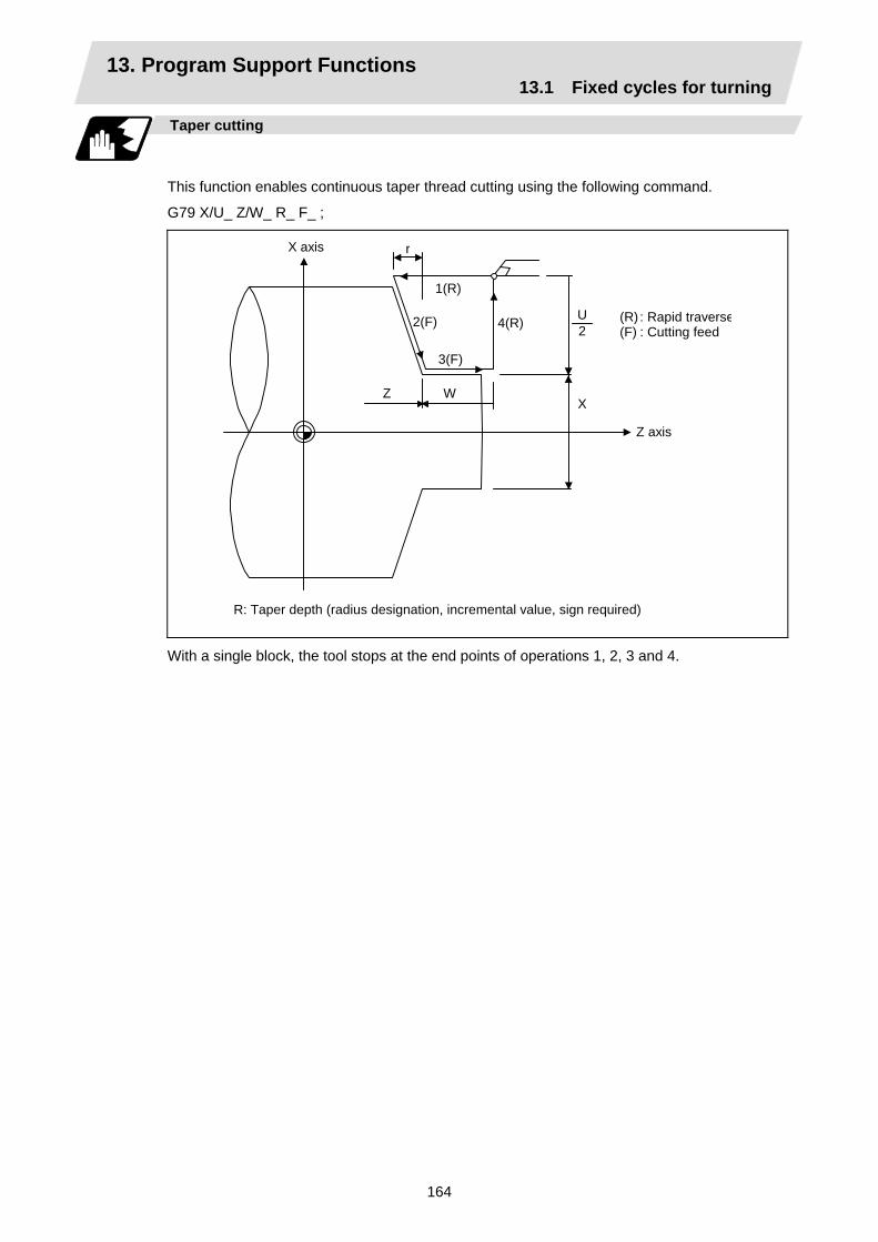
13. Program Support Functions 13.1 Fixed cycles for turning
164
Taper cutting
This function enables continuous taper thread cutting using the following command.
G79 X/U_ Z/W_ R_ F_ ;
X axis
Z axis
XZ W
3(F)
2(F) 4(R)
1(R)
r
U2
(R) : Rapid traverse(F) : Cutting feed
R: Taper depth (radius designation, incremental value, sign required)
With a single block, the tool stops at the end points of operations 1, 2, 3 and 4.
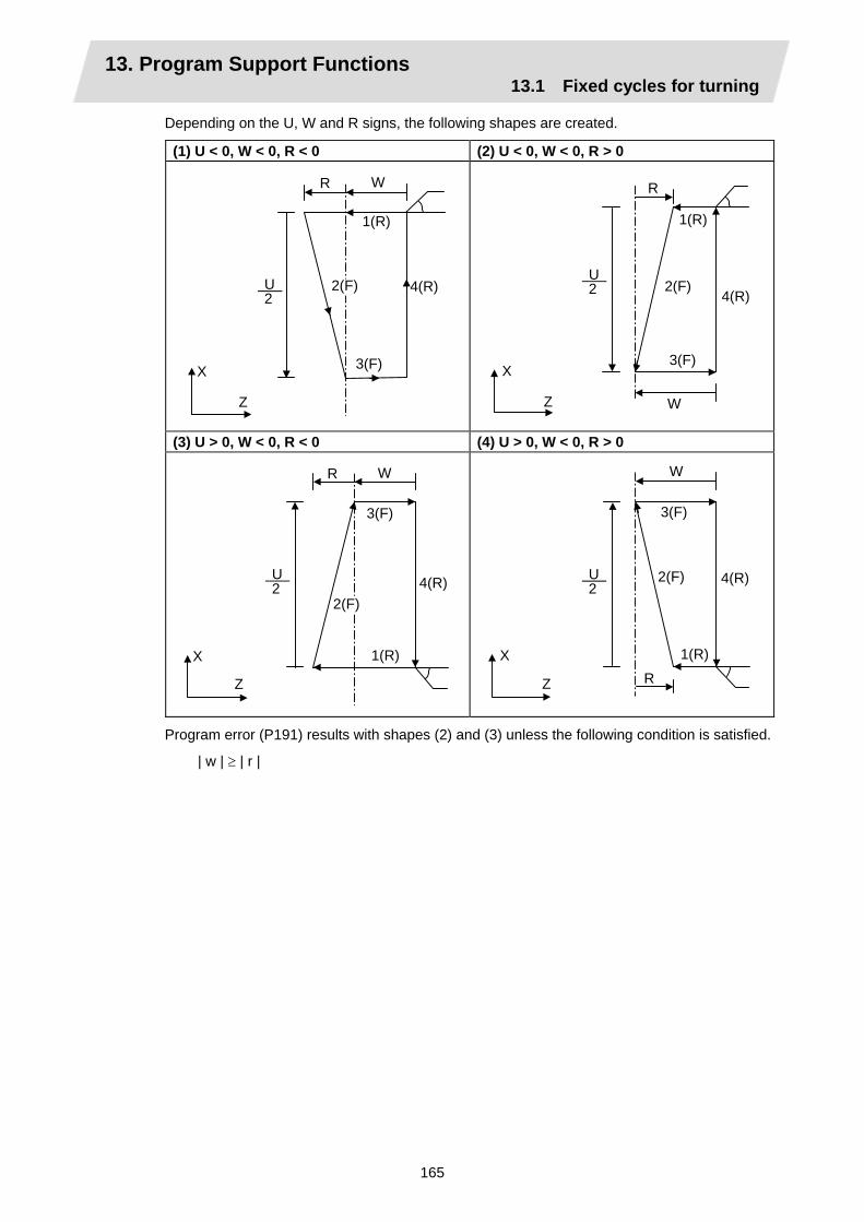
13. Program Support Functions 13.1 Fixed cycles for turning
165
Depending on the U, W and R signs, the following shapes are created.
(1) U < 0, W < 0, R < 0 (2) U < 0, W < 0, R > 0
WR
X
Z
U 2
1(R)
3(F)
4(R)2(F)
W
R
X
Z
U 2
1(R)
2(F)
3(F)
4(R)
(3) U > 0, W < 0, R < 0 (4) U > 0, W < 0, R > 0
WR
X
Z
U 2
1(R)
3(F)
4(R)2(F)
W
R
X
Z
U 2
1(R)
2(F)
3(F)
4(R)
Program error (P191) results with shapes (2) and (3) unless the following condition is satisfied.
| w | ≥ | r |
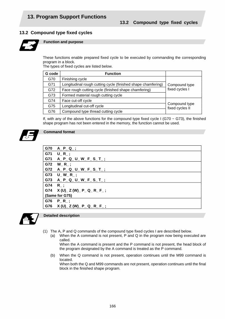
13. Program Support Functions 13.2 Compound type fixed cycles
166
13.2 Compound type fixed cycles
Function and purpose
These functions enable prepared fixed cycle to be executed by commanding the corresponding program in a block. The types of fixed cycles are listed below.
G code Function G70 Finishing cycle G71 Longitudinal rough cutting cycle (finished shape chamfering) G72 Face rough cutting cycle (finished shape chamfering) G73 Formed material rough cutting cycle
Compound type fixed cycles I
G74 Face cut-off cycle G75 Longitudinal cut-off cycle G76 Compound type thread cutting cycle
Compound type fixed cycles II
If, with any of the above functions for the compound type fixed cycle I (G70 ~ G73), the finished shape program has not been entered in the memory, the function cannot be used.
Command format
G70 A_ P_ Q_ ; G71 U_ R_ ; G71 A_ P_ Q_ U_ W_ F_ S_ T_ ; G72 W_ R_ ; G72 A_ P_ Q_ U_ W_ F_ S_ T_ ; G73 U_ W_ R_ ; G73 A_ P_ Q_ U_ W_ F_ S_ T_ ; G74 R_ ; G74 X (U)_ Z (W)_ P_ Q_ R_ F_ ; (Same for G75) G76 P_ R_ ; G76 X (U)_ Z (W)_ P_ Q_ R_ F_ ;
Detailed description
(1) The A, P and Q commands of the compound type fixed cycles I are described below.
(a) When the A command is not present, P and Q in the program now being executed are called. When the A command is present and the P command is not present, the head block of the program designated by the A command is treated as the P command.
(b) When the Q command is not present, operation continues until the M99 command is located. When both the Q and M99 commands are not present, operation continues until the final block in the finished shape program.

13. Program Support Functions 13.2 Compound type fixed cycles
167
13.2.1 Longitudinal rough cutting cycle; G71
Function and purpose
This function calls the finished shape program and, while automatically calculating the tool path, performs rough cutting in the longitudinal direction.
Command format
G71 Ud Re ; G71 Aa Pp Qq Uu Ww Ff Ss Tt ; Ud Re Aa Pp Qq Uu Ww Ff Ss Tt
Cut amount "d" (cut amount without P, Q commands) (modal) Retract amount "e" (modal) Finished shape program number (program being executed when omitted) Finished shape start sequence number (program head when omitted) Finished shape end sequence number (up to end of program when omitted) Up to M99 command when M99 comes first even if Q command is present X-axis direction finishing allowance (diameter or radius designation) Z-axis direction finishing allowance Cutting feedrate Spindle speed Tool command The F, S and T commands in the finished shape program are ignored, and the value in the rough cutting cycle command or a value prior to it is validated.
(R)
(Cycle command point)
d Cut amount
Detail of retract operation (R)
(F)
(F) 45° e
u/2
WFinishing allowance
X
Z
(Note) The U command applied to the finishing allowance when it is in the same block as the A, P
and Q commands.
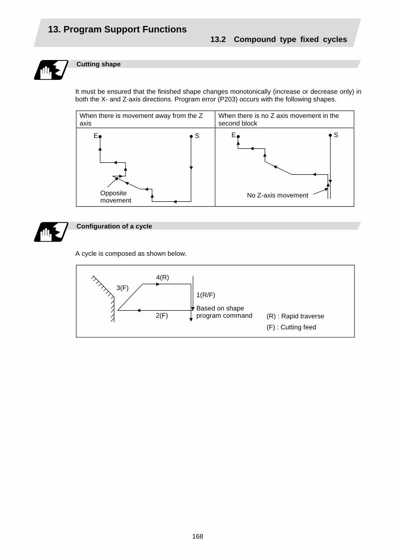
13. Program Support Functions 13.2 Compound type fixed cycles
168
Cutting shape
It must be ensured that the finished shape changes monotonically (increase or decrease only) in both the X- and Z-axis directions. Program error (P203) occurs with the following shapes.
When there is movement away from the Z axis
When there is no Z axis movement in the second block
E S
Opposite movement
E S
No Z-axis movement
Configuration of a cycle
A cycle is composed as shown below.
3(F)
2(F)
4(R)
(R) : Rapid traverse (F) : Cutting feed
1(R/F)
Based on shape program command

13. Program Support Functions 13.2 Compound type fixed cycles
169
Cut amount
The cut amount is designated by "d". However, it is possible to change the cut amount with each cutting pass by setting the cut change amount (∆d) using a parameter (#8017 G71 DELTA-D). Program error (P204) results when the amount of one cut commanded in the program is deeper than the cutting depth of the final shape, in other words, when "d" is less than "∆d".
d+Δd
d
d-Δd
d+Δd
d, d-Δd, d+Δd,
Remainder
…d, d–∆d, d + ∆d are repeated
1st cutting pass d + ∆d
2nd cutting pass d
3rd cutting pass d – ∆d
4th cutting pass d + ∆d
Final cutting pass Remainder
1
2
3
4
n
Tool nose R compensation
When this cycle is commanded with the tool nose R compensation mode still in force, tool nose R compensation is applied to the finished shape program covered by this cycle and the cycle is executed for this shape. However, when this cycle is commanded with the tool nose R compensation mode still in force, the mode is temporarily canceled immediately before the cycle and it starts up with the finished shape program, the end block of this program serves as the pre-read prohibit block, and then compensation is applied to the shape and executed.
Shape with tool noseR compensation applied
Temporary cancellation
Finished shape program
G71A_ U_ W_ ..... ; Command point

13. Program Support Functions 13.2 Compound type fixed cycles
170
Others
(1) After the cutting, the remainder is made the cut amount. However, if this amount is less than
the value set by parameter (#8016 G71 MINIMUM), finishing rough cutting is executed and the workpiece is not cut.
(2) Finishing allowance direction The finishing allowance direction is determined by the shape as follows. A→B→C apply for the finishing program.
A
B
C
U(+)W(-)
II
A
B
C
U(+)W(+)
I
A
B
C
U(-)W(+)
IV
A
B
C
U(-)W(-) III
X
Z

13. Program Support Functions 13.2 Compound type fixed cycles
171
13.2.2 Face rough cutting cycle; G72
Function and purpose
This function calls the finished shape program and, while automatically calculating the path, performs rough cutting in the face direction.
Command format
G72 Wd Re ; G72 Aa Pp Qq Uu Ww Ff Ss Tt ; Wd Re Aa Pp Qq Uu Ww Ff Ss Tt
Cut amount "d" (cut amount without P, Q commands) (modal) Retract amount "e" (modal) Finished shape program number (program being executed when omitted) Finished shape start sequence number (program head when omitted) Finished shape end sequence number (up to end of program when omitted) Up to M99 command when M99 comes first even if Q command is present X-axis direction finishing allowance (diameter or radius designation) Z-axis direction finishing allowance Cutting feedrate Spindle speed Tool command The F, S and T commands in the finished shape program are ignored, and the value in the rough cutting cycle command or a value prior to it is validated.
Cycle command point
d Cut amount
u/2
W
Finishing allowance
(R)
Detail of retract operation
(F)
(F)
e
X
Z
45°
S
E
(Note) The U command applied to the finishing allowance when it is in the same block as the A, P
and Q commands.
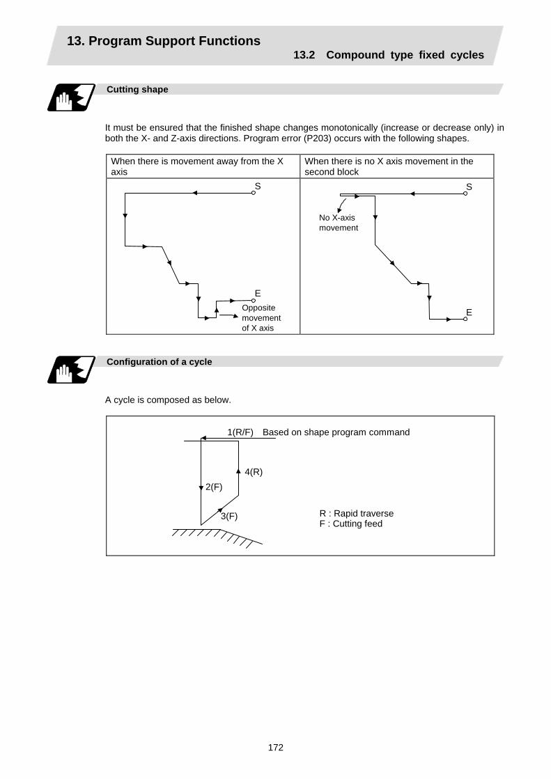
13. Program Support Functions 13.2 Compound type fixed cycles
172
Cutting shape
It must be ensured that the finished shape changes monotonically (increase or decrease only) in both the X- and Z-axis directions. Program error (P203) occurs with the following shapes.
When there is movement away from the X axis
When there is no X axis movement in the second block
S
EOpposite movement of X axis
S
E
No X-axismovement
Configuration of a cycle
A cycle is composed as below.
1(R/F) Based on shape program command
2(F) 4(R)
3(F) R : Rapid traverse F : Cutting feed

13. Program Support Functions 13.2 Compound type fixed cycles
173
Cut amount
The cut amount is designated by "d". However, it is possible to change the cut amount with each cutting pass by setting the cut change amount (∆d) using a parameter (#8017 G71 DELTA-D).
d+Δdd d-Δd d+Δd
d,d-Δd,d+Δd,Remainder …
1 2 341st cutting pass d + ∆d 2nd cutting pass d 3rd cutting pass d – ∆d 4th cutting pass d + ∆d
d, d–∆d, d + ∆d are repeated Final cutting pass Remainder
Tool nose R compensation
When this cycle is commanded with the tool nose R compensation mode still in force, tool nose R compensation is applied to the finished shape program covered by this cycle and the cycle is executed for this shape. However, when this cycle is commanded with the tool nose R compensation mode still in force, the mode is temporarily canceled immediately before the cycle and it starts up with the finished shape program, the end block of this program serves as the pre-read prohibit block, and then compensation is applied to the shape and executed.
Finished shape program
Shape with tool nose R compensation applied
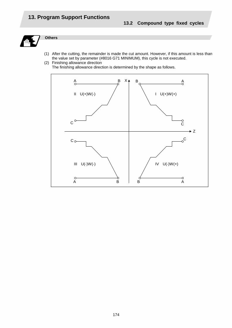
13. Program Support Functions 13.2 Compound type fixed cycles
174
Others
(1) After the cutting, the remainder is made the cut amount. However, if this amount is less than
the value set by parameter (#8016 G71 MINIMUM), this cycle is not executed. (2) Finishing allowance direction
The finishing allowance direction is determined by the shape as follows.
A B
C
II U(+)W(-)
A B
C
I U(+)W(+)
A B
C
III U(-)W(-)
A B
C
IV U(-)W(+)
X
Z

13. Program Support Functions 13.2 Compound type fixed cycles
175
13.2.3 Formed material rough cutting cycle; G73
Function and purpose
This calls the finished shape program, automatically calculates the path and performs rough cutting while cutting the workpiece into the finished shape.
Command format
G73 Ui Wk Rd ; G73 Aa Pp Qq Uu Ww Ff Ss Tt ;
Ui Wk Rd
X-axis direction cutting allowance Z-axis direction cutting allowance Number of divisions
ikd
• Cutting allowances when P, Q commands are not present
• Modal data • Sign is ignored • Radius designation applies to the
cutting allowance. Aa Pp Qq
Finished shape program number Finished shape start sequence number Finished shape end sequence number
(program being executed when omitted)(program head when omitted) (up to end of program or M99 when omitted) Note that this is up to M99 when M99 comes first, even when there is a Qq command.
Uu Ww
X-axis direction finishing allowanceZ-axis direction finishing allowance
uw
• Cutting allowance when P, Q commands are present
• Sign is ignored. • Diameter/radius designation changes
in accordance with the parameters (#1019 dia).
• The shift direction is determined by the shape. For details, refer to the "finishing allowance direction" for G71.
Ff Ss Tt
Cutting feedrate (F function) Spindle speed (S function) Tool command (T function)
The F, S and T commands in the finishedshape program are ignored and the valuein the rough cutting cycle command or previous value is valid.

13. Program Support Functions 13.2 Compound type fixed cycles
176
k + w
X
Z
S1 S2
S3
S
i + u/2
u/2 wA
E
2
34
56
7
8
910
1112
13
14
1516
1718
19
1
(Note) With a single block, operation stops at the end point of each block.
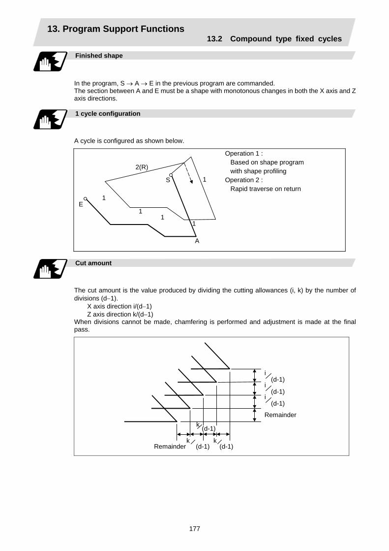
13. Program Support Functions 13.2 Compound type fixed cycles
177
Finished shape
In the program, S → A → E in the previous program are commanded. The section between A and E must be a shape with monotonous changes in both the X axis and Z axis directions.
1 cycle configuration
A cycle is configured as shown below.
1
1
1 1
1
2(R)
S
E
A
Operation 1 : Based on shape program with shape profiling Operation 2 : Rapid traverse on return
Cut amount
The cut amount is the value produced by dividing the cutting allowances (i, k) by the number of divisions (d−1).
X axis direction i/(d−1) Z axis direction k/(d−1)
When divisions cannot be made, chamfering is performed and adjustment is made at the final pass.
i(d-1)
i(d-1)
i(d-1)
Remainder
k kRemainder (d-1) (d-1)
k (d-1)
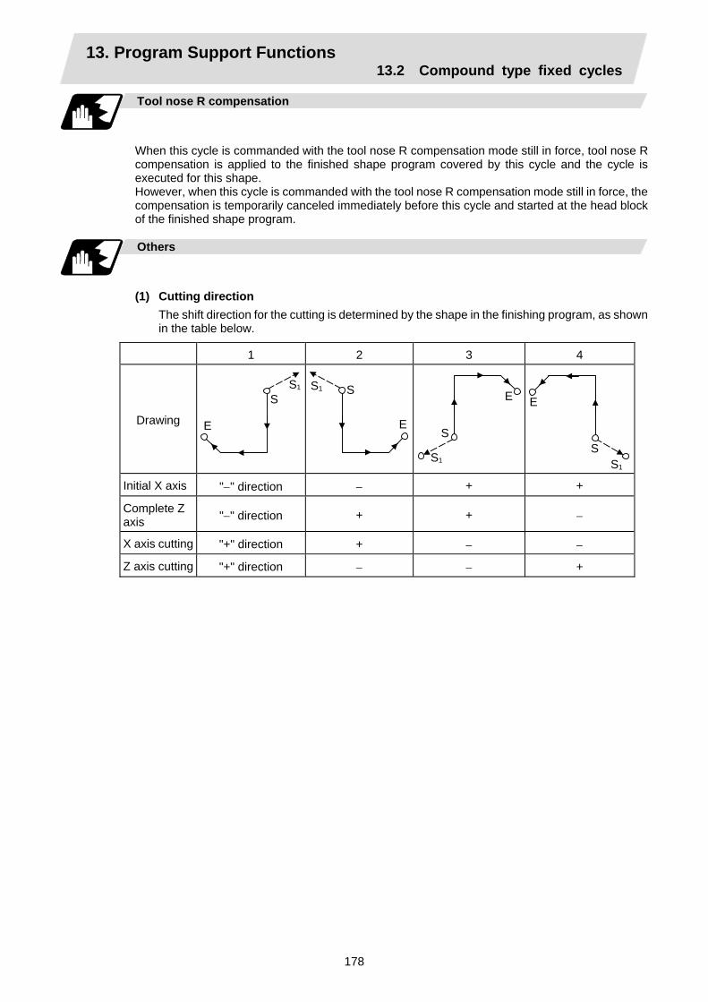
13. Program Support Functions 13.2 Compound type fixed cycles
178
Tool nose R compensation
When this cycle is commanded with the tool nose R compensation mode still in force, tool nose R compensation is applied to the finished shape program covered by this cycle and the cycle is executed for this shape. However, when this cycle is commanded with the tool nose R compensation mode still in force, the compensation is temporarily canceled immediately before this cycle and started at the head block of the finished shape program.
Others
(1) Cutting direction
The shift direction for the cutting is determined by the shape in the finishing program, as shown in the table below.
1 2 3 4
Drawing
E
S S1
E
SS1
E
S
S1
E
SS1
Initial X axis "−" direction − + +
Complete Z axis "−" direction + + −
X axis cutting "+" direction + − −
Z axis cutting "+" direction − − +

13. Program Support Functions 13.2 Compound type fixed cycles
179
13.2.4 Finishing cycle; G70
Function and purpose
After rough cutting have been carried out by the G71 ~ G73 commands, finishing cutting can be performed by the following command.
Command format
G70 A_ P_ Q_ ; A P Q
Finished shape program number (program being executed when omitted) Finished shape start sequence number (program head when omitted) Finished shape end sequence number (up to end of program when omitted) Note that this is up to M99 when M99 comes first, even when there is a Q command.
Detailed description
(1) The F, S and T commands in the finished shape program are valid during the finishing cycle.
(2) When the G70 cycle is completed, the tool returns to the start point by rapid traverse and the next block is read.
(Example 1) When a sequence number is designated
N200 ……… ; N300 ……… ;
N100 G70 P200 Q300 ;
N110
N120
N200
Finished shape program
N300
N310
~~
~
~
~
(Example 2) When a program number is designated
N100 G70 A100 ; N110 ……… ; N120 ……… ;
~~
O100
G01 X100 Z50 F0.5 ; M99 ;
~
If the N100 cycle is executed in either Example 1 or Example 2, the N110 block is executed next.

13. Program Support Functions 13.2 Compound type fixed cycles
180
13.2.5 Face cut-off cycle; G74
Function and purpose
The G74 fixed cycle automatically enters a groove in the face direction of the workpiece by commanding the coordinates of the groove end point, cut amount, cutter shift amount and cutter escape at the bottom of the cut. The machining program commands are as follows.
Command format
G74 Re ; C74 X/(U)x Z/(w)z Pi Qk Rd Ff ; Re X/Ux Z/Wz Pi Qk
Return amount (no X/U, P commands) (modal) B point X coordinate (absolute/incremental value) B point Z coordinate (absolute/incremental value) Tool shift amount (radius designation, incremental value, sign not required) Cut amount (radius designation, incremental value, sign not required)
Rd
Escape at the bottom of the cut
When there is no sign, escapes even at the bottom of the first cut. When a - sign is attached, the tool escapes from the second cut without escaping the first cut.
Ff Feedrate
k k k kx
u/2
(1)(2)(3)(4)
(5)(6)(7)(8)
(9)(10)
(11)
(12)i
d
e
wz
B
• Operation (9) as well as operation (12) immediately before the final cycle are executed with the remainderamount.
• Operations (2), (4), (6), (8), (10), (11) and (12) are executed at the rapid traverse rate.
S (Start point)

13. Program Support Functions 13.2 Compound type fixed cycles
181
Single block stop
Operation stops at each block from (1) to (12).
Others
(1) When X/U and P are omitted or when the values of "x" and "i" are zero, operation will apply to
the Z axis only. Note that when there is an Rd command and no sign, the tool will escape at the bottom of the cut.
(2) A case where the X/U or Z/W command is not present is treated as the assignment of a parameter setting command (G74 Re). Even when G74 Pi Qk Rd ; is commanded, Rd is regarded as Re, and the return amount is set.
(3) The escape direction does not change when a - sign is attached to the Rd command, or when there is no sign.
(4) A program error (P204) results in the following cases.
(a) When " i " is zero or P has not been commanded even though X/U has been commanded.
(b) When tool shift amount " i " is greater than the "x" movement amount.
(c) When the escape amount "d" is greater than the shift amount " i ".
(d) When the return amount "e" is greater than the cut amount "k".
(e) When the cut in amount "k" is larger than the hole depth "w".
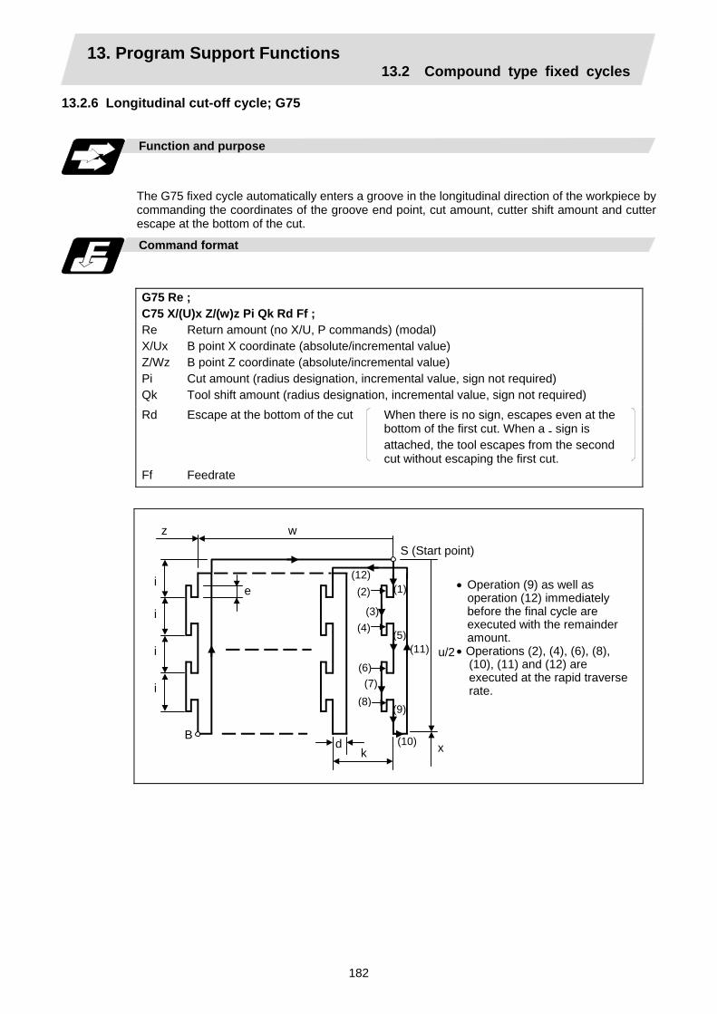
13. Program Support Functions 13.2 Compound type fixed cycles
182
13.2.6 Longitudinal cut-off cycle; G75
Function and purpose
The G75 fixed cycle automatically enters a groove in the longitudinal direction of the workpiece by commanding the coordinates of the groove end point, cut amount, cutter shift amount and cutter escape at the bottom of the cut.
Command format
G75 Re ; C75 X/(U)x Z/(w)z Pi Qk Rd Ff ; Re X/Ux Z/Wz Pi Qk
Return amount (no X/U, P commands) (modal) B point X coordinate (absolute/incremental value) B point Z coordinate (absolute/incremental value) Cut amount (radius designation, incremental value, sign not required) Tool shift amount (radius designation, incremental value, sign not required)
Rd
Escape at the bottom of the cut When there is no sign, escapes even at the bottom of the first cut. When a - sign is attached, the tool escapes from the second cut without escaping the first cut.
Ff Feedrate
k x
u/2
(1)(2)
(3)(4)
(5)
(6)(7)
(8)(9)
(10)
(11)
(12)i
d
e
wz
B
S (Start point)
• Operation (9) as well as operation (12) immediately before the final cycle are executed with the remainder amount.
• Operations (2), (4), (6), (8), (10), (11) and (12) are executed at the rapid traverserate.
i
i
i
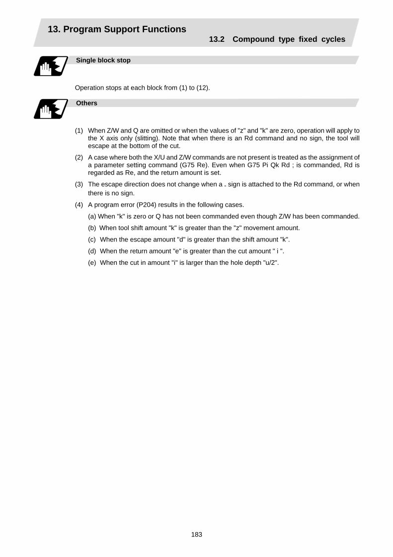
13. Program Support Functions 13.2 Compound type fixed cycles
183
Single block stop
Operation stops at each block from (1) to (12).
Others
(1) When Z/W and Q are omitted or when the values of "z" and "k" are zero, operation will apply to
the X axis only (slitting). Note that when there is an Rd command and no sign, the tool will escape at the bottom of the cut.
(2) A case where both the X/U and Z/W commands are not present is treated as the assignment of a parameter setting command (G75 Re). Even when G75 Pi Qk Rd ; is commanded, Rd is regarded as Re, and the return amount is set.
(3) The escape direction does not change when a - sign is attached to the Rd command, or when there is no sign.
(4) A program error (P204) results in the following cases.
(a) When "k" is zero or Q has not been commanded even though Z/W has been commanded.
(b) When tool shift amount "k" is greater than the "z" movement amount.
(c) When the escape amount "d" is greater than the shift amount "k".
(d) When the return amount "e" is greater than the cut amount " i ".
(e) When the cut in amount "i" is larger than the hole depth "u/2".

13. Program Support Functions 13.2 Compound type fixed cycles
184
13.2.7 Compound type thread cutting cycle; G76
Function and purpose
The G76 fixed cycle enables the workpiece to be cut at the desired angle by designating the thread cutting start point and end point, and it automatically cuts so that the cutting cross section (cutting torque) per cutting pass is constant. Various longitudinal direction threads can be cut by bearing in mind the command value for the thread end point coordinate and taper height component.
Command format
G76 Pmra Rd ; G75 X/U Z/W Ri Pk Q∆d Fl ; m Number of cutting passes for finishing: 00 ~ 99 (times) (modal) r
Chamfering amount: 00 ~ 99 (0.1mm/rev) (modal) The chamfering width based on thread lead "l " is designated by a 2-digit integer without decimal point from 0.0 to 9.9.
a
Tool nose angle (thread angle): 00 ~ 99 (°) (modal) The angle from 0° to 99° is assigned in 1° units. "m", "r" and "a" are commanded in succession in address P. (Example) When m=5, r=1.5 and a=0° P is 051500 and the leading and trailing
zeroes cannot be omitted. d Finishing allowance 0 ~ 9999 (µm) (modal) X/U
X-axis end point coordinate of thread The X coordinate of the end point for the thread is commanded by an absolute or incremental value.
Z/W
Z-axis end point coordinate of thread The Z coordinate of the end point for the thread is commanded by an absolute or incremental value.
i Taper height component (radius value) for thread straight thread when "i" is zero k Thread height
This is commanded by a positive radial value. ∆d
Cut amount The cut amount of the first cutting pass is commanded by a positive radius value.
l Thread lead
(Note 1) The two above G76 commands cannot be placed in the same block. The data commanded by P, Q and R are automatically identified according to the
presence or absence of the X/U and Z/W axis addresses.
(Note 2) Parameter settings can be used for the above "r" modal data but these parameter (#8014 chamfer amount) settings are rewritten by the program commands.
(Note 3) The chamfering amount designation is valid even for thread cutting fixed cycles.
(Note 4) Program error (P204) results in the following cases.
(a) When "a" is outside the rating
(b) When both the X and Z commands have not been issued or when the start and end point coordinates are the same for either the X or Z command.
(c) When the thread is greater than the movement of the X axis at the thread bottom
(Note 5) The precautions for the thread cutting command (G33) and thread cutting cycle (G78) should be observed.

13. Program Support Functions 13.2 Compound type fixed cycles
185
1 cycle configuration
The tool moves at rapid traverse for operations (1), (2), (5) and (6) in the cycle and at the cutting feed based on the F designation for operations (3) and (4).
When Ri is negative rx
( -i)
z w
S
u/2
(1)
(2)
(3)
(4)
(5)
(6)
a°/2
When Ri is positiver
x
i
k
z w
S
u/2
(1)
(2)
(3)(4)
(5)
(6)
a°/2

13. Program Support Functions 13.2 Compound type fixed cycles
186
k
a° ∆d for 1st cutting pass
2nd cutting pass
∆d × √ 2 nth cutting pass ∆d × √ n
Finishing allowance "d" (cutting results for "m" number of passes)
Example of program
30.0
24.0 46.0
6.0
0.2
9.0
32.0
1.5l
The tool moves with rapid traverse over the solid line section, and at the cutting feed that is F-designated over the thread cutting sections.
Z axis
X axis
G76 P011560 R0.2 ; G76 U−28.0 W−46.0 R9.0 P6.0 Q3.5 F4.0 ;

13. Program Support Functions 13.2 Compound type fixed cycles
187
Interrupt operation
(1) When the feed hold button is pressed while G76 is being executed, automatic operation will
stop upon completion of a block without thread cutting if thread cutting is ongoing. (The automatic operation pause lamp lights immediately in the feed hold mode and it goes off when automatic operation stops.) If feed hold is applied when no thread is then being cut, or if applied in the interval from the execution of the thread cutting command to the axis movement, the automatic operation pause lamp will turn ON, and the automatic operation will pause.
(2) The tool stops upon completion of operations (1), (4) and (5) when the mode is switched to another automatic operation mode during the G76 command execution, when automatic operation is changed to manual operations or when single block operation is conducted.
(3) The dry run valid/invalid status during G76 execution does not change during thread cutting.

13. Program Support Functions 13.2 Compound type fixed cycles
188
13.2.8 Precautions for compound type fixed cycles; G70 ~ G76
Precautions
(1) Command all required parameters in a compound type fixed cycle command block.
(2) Provided that the finished shape program has been entered in the memory, compound fixed cycle I commands can be executed in the memory or MDI operation mode.
(3) When executing a G70 ~ G73 command, ensure that the sequence number of the finished shape program which is stop with P and Q is not duplicated in that program.
(4) The finished shape program specified by P and Q in the G71 ~ G73 blocks should be prepared so that the maximum number of blocks is 50 for all the commands for corner chamfering, corner rounding and other commands including the automatic insertion blocks based on tool nose R compensation. If this number is exceeded, program error (P202) results.
(5) The finished shape program which is designated by the G71 ~ G73 blocks should be a program with monotonous changes (increases or reductions only) for both the X and Z axes.
(6) Blocks without movement in the finished shape program are ignored.
(7) N, F, S, M, and T commands in the finished shape program are ignored.
(8) When any of the following commands are present in a finished shape program, program error (P201) results.
(a) Commands related to reference point return (G27, G28, G29, G30)
(b) Thread cutting (G33)
(c) Fixed cycles
(d) Skip functions (G31, G37)
(9) If subprogram call or macro call commands are present in the finished shape program, these commands will also be executed.
(10) Except for thread cutting cycles, operation stops at the end (start) point of each block in the single block mode.
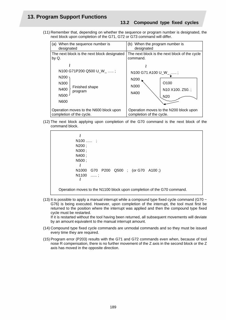
13. Program Support Functions 13.2 Compound type fixed cycles
189
(11) Remember that, depending on whether the sequence or program number is designated, the next block upon completion of the G71, G72 or G73 command will differ.
(a) When the sequence number is designated
(b) When the program number is designated
The next block is the next block designated by Q.
The next block is the next block of the cycle command.
N100 G71P200 Q500 U_W_ ….. ;N200 N300 N400 N500 N600
~
Finished shapeprogram
N100 G71 A100 U_W_ ….. ;
N200
N300
N400
~
O100
N10 X100. Z50. ;
N20
Operation moves to the N600 block upon completion of the cycle.
Operation moves to the N200 block upon completion of the cycle.
(12) The next block applying upon completion of the G70 command is the next block of the command block.
N100 ...... ; N200 ; N300 ; N400 ; N500 ; N1000 G70 P200 Q500 ; (or G70 A100 ;) N1100 ...... ;
~
~
~
Operation moves to the N1100 block upon completion of the G70 command.
(13) It is possible to apply a manual interrupt while a compound type fixed cycle command (G70 ~ G76) is being executed. However, upon completion of the interrupt, the tool must first be returned to the position where the interrupt was applied and then the compound type fixed cycle must be restarted.
If it is restarted without the tool having been returned, all subsequent movements will deviate by an amount equivalent to the manual interrupt amount.
(14) Compound type fixed cycle commands are unmodal commands and so they must be issued every time they are required.
(15) Program error (P203) results with the G71 and G72 commands even when, because of tool nose R compensation, there is no further movement of the Z axis in the second block or the Z axis has moved in the opposite direction.
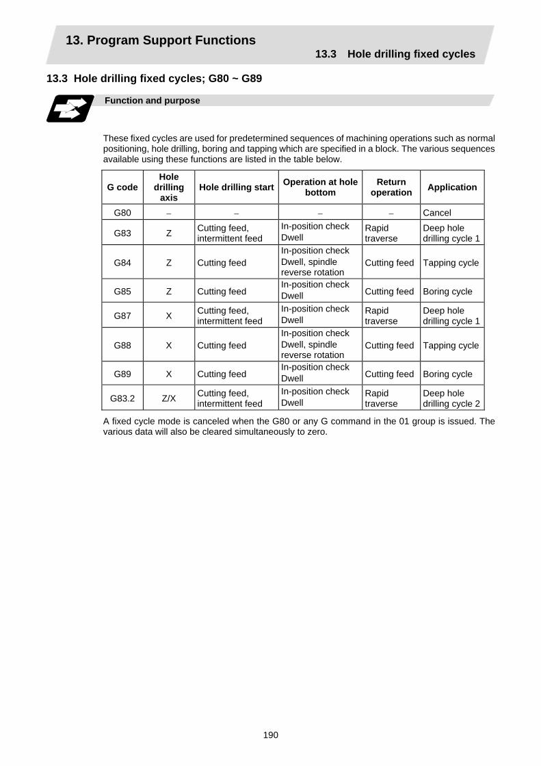
13. Program Support Functions 13.3 Hole drilling fixed cycles
190
13.3 Hole drilling fixed cycles; G80 ~ G89
Function and purpose
These fixed cycles are used for predetermined sequences of machining operations such as normal positioning, hole drilling, boring and tapping which are specified in a block. The various sequences available using these functions are listed in the table below.
G code Hole
drilling axis
Hole drilling start Operation at hole bottom
Return operation Application
G80 − − − − Cancel
G83 Z Cutting feed, intermittent feed
In-position check Dwell
Rapid traverse
Deep hole drilling cycle 1
G84 Z Cutting feed In-position check Dwell, spindle reverse rotation
Cutting feed Tapping cycle
G85 Z Cutting feed In-position check Dwell Cutting feed Boring cycle
G87 X Cutting feed, intermittent feed
In-position check Dwell
Rapid traverse
Deep hole drilling cycle 1
G88 X Cutting feed In-position check Dwell, spindle reverse rotation
Cutting feed Tapping cycle
G89 X Cutting feed In-position check Dwell Cutting feed Boring cycle
G83.2 Z/X Cutting feed, intermittent feed
In-position check Dwell
Rapid traverse
Deep hole drilling cycle 2
A fixed cycle mode is canceled when the G80 or any G command in the 01 group is issued. The various data will also be cleared simultaneously to zero.

13. Program Support Functions 13.3 Hole drilling fixed cycles
191
Command format
(1) Face hole drilling
G8∆ X/U C/H Z/W R Q P F K S ,S M ; G8∆ X/U C/H Z/W R Q P F K S ,S M
Hole machining mode (G83, G84, G85) Hole positioning data Hole machining data Number of repetitions Spindle rotation speed Spindle rotation speed at return Miscellaneous command
(2) Longitudinal hole drilling
G8* Z/W C/H X/U R Q P F K S ,S M ; G8* Z/W C/H X/U R Q P F K S ,S M
Hole machining mode (G87, G88, G89) Hole positioning data Hole machining data Number of repetitions Spindle rotation speed Spindle rotation speed at return Miscellaneous command
(3) Cancel
G80 ;
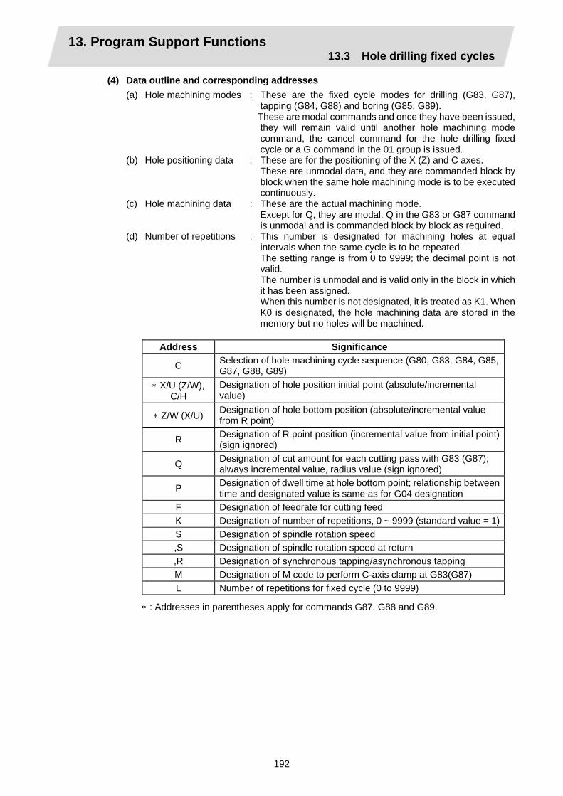
13. Program Support Functions 13.3 Hole drilling fixed cycles
192
(4) Data outline and corresponding addresses (a) Hole machining modes : These are the fixed cycle modes for drilling (G83, G87),
tapping (G84, G88) and boring (G85, G89). These are modal commands and once they have been issued,
they will remain valid until another hole machining mode command, the cancel command for the hole drilling fixed cycle or a G command in the 01 group is issued.
(b) Hole positioning data : These are for the positioning of the X (Z) and C axes. These are unmodal data, and they are commanded block by
block when the same hole machining mode is to be executed continuously.
(c) Hole machining data : These are the actual machining mode. Except for Q, they are modal. Q in the G83 or G87 command
is unmodal and is commanded block by block as required. (d) Number of repetitions : This number is designated for machining holes at equal
intervals when the same cycle is to be repeated. The setting range is from 0 to 9999; the decimal point is not
valid. The number is unmodal and is valid only in the block in which
it has been assigned. When this number is not designated, it is treated as K1. When
K0 is designated, the hole machining data are stored in the memory but no holes will be machined.
Address Significance
G Selection of hole machining cycle sequence (G80, G83, G84, G85, G87, G88, G89)
∗ X/U (Z/W), C/H
Designation of hole position initial point (absolute/incremental value)
∗ Z/W (X/U) Designation of hole bottom position (absolute/incremental value from R point)
R Designation of R point position (incremental value from initial point) (sign ignored)
Q Designation of cut amount for each cutting pass with G83 (G87); always incremental value, radius value (sign ignored)
P Designation of dwell time at hole bottom point; relationship between time and designated value is same as for G04 designation
F Designation of feedrate for cutting feed K Designation of number of repetitions, 0 ~ 9999 (standard value = 1)S Designation of spindle rotation speed ,S Designation of spindle rotation speed at return ,R Designation of synchronous tapping/asynchronous tapping M Designation of M code to perform C-axis clamp at G83(G87) L Number of repetitions for fixed cycle (0 to 9999)
∗ : Addresses in parentheses apply for commands G87, G88 and G89.

13. Program Support Functions 13.3 Hole drilling fixed cycles
193
Detailed description
The hole drilling axes for the hole drilling fixed cycle and the positioning are shown in the outline drawing below.
+X +Z
r4
z4 C
x2 r2
q2z2
q4x4 (1)
(2)
(3) (4)
Commands M03, M04 and M05 (forward rotation, reverse rotation and stop) apply to the rotary tools.
During the hole drilling cycle, the C axis (spindle) is clamped so that it does not move.
Rotary tool for X axis
Rotary tool for Z axis
(1) G83 Xx1 Cc1 Zz1 Rr1 Qq1 Pp1 Ff1 Kk1 ; (2) G83 Xx2 Cc2 Zz2 Rr2 Qq2 Pp2 Ff2 Kk2 ; (3) G87 Zz3 Cc3 Xx3 Rr3 Qq3 Pp3 Ff3 Kk3 ; (4) G87 Zz4 Cc4 Xx4 Rr4 Qq4 Pp4 Ff4 Kk4 ;
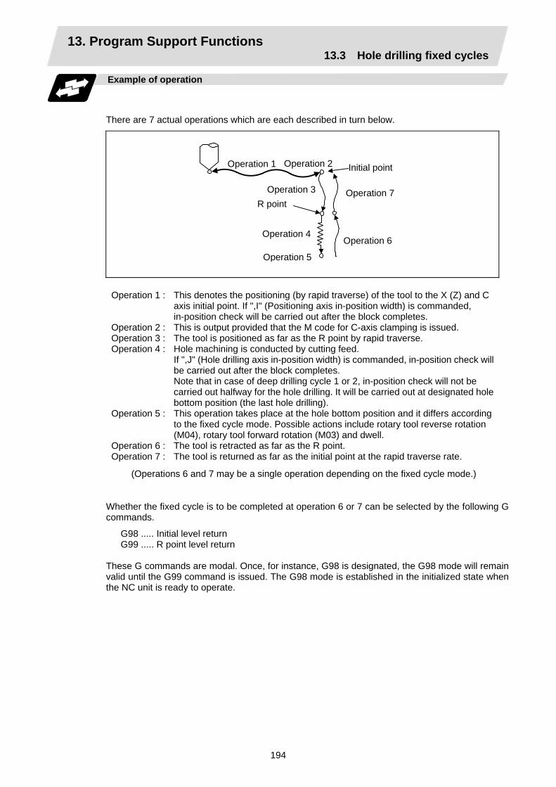
13. Program Support Functions 13.3 Hole drilling fixed cycles
194
Example of operation
There are 7 actual operations which are each described in turn below.
Operation 1 Operation 2
Operation 4
Operation 3
Operation 5
Operation 6
Operation 7 R point
Initial point
Operation 1 : This denotes the positioning (by rapid traverse) of the tool to the X (Z) and C axis initial point. If ",I" (Positioning axis in-position width) is commanded, in-position check will be carried out after the block completes.
Operation 2 : This is output provided that the M code for C-axis clamping is issued. Operation 3 : The tool is positioned as far as the R point by rapid traverse. Operation 4 : Hole machining is conducted by cutting feed.
If ",J" (Hole drilling axis in-position width) is commanded, in-position check will be carried out after the block completes. Note that in case of deep drilling cycle 1 or 2, in-position check will not be carried out halfway for the hole drilling. It will be carried out at designated hole bottom position (the last hole drilling).
Operation 5 : This operation takes place at the hole bottom position and it differs according to the fixed cycle mode. Possible actions include rotary tool reverse rotation (M04), rotary tool forward rotation (M03) and dwell.
Operation 6 : The tool is retracted as far as the R point. Operation 7 : The tool is returned as far as the initial point at the rapid traverse rate.
(Operations 6 and 7 may be a single operation depending on the fixed cycle mode.)
Whether the fixed cycle is to be completed at operation 6 or 7 can be selected by the following G commands.
G98 ..... Initial level return G99 ..... R point level return
These G commands are modal. Once, for instance, G98 is designated, the G98 mode will remain valid until the G99 command is issued. The G98 mode is established in the initialized state when the NC unit is ready to operate.
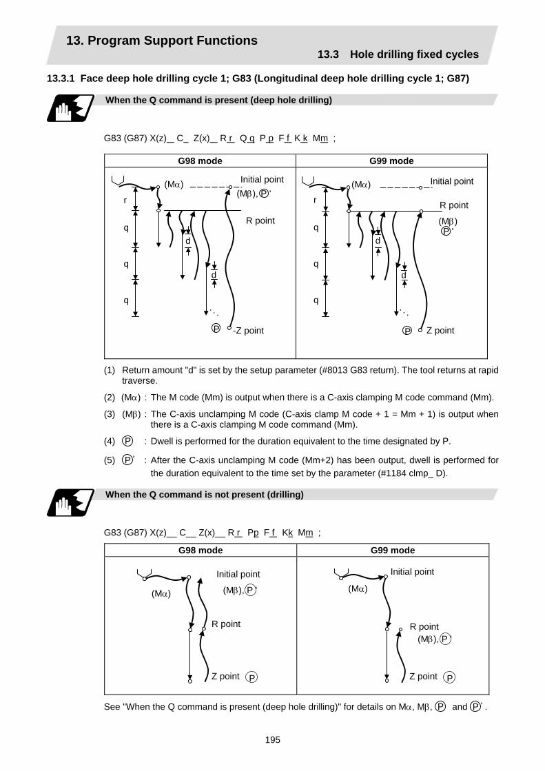
13. Program Support Functions 13.3 Hole drilling fixed cycles
195
13.3.1 Face deep hole drilling cycle 1; G83 (Longitudinal deep hole drilling cycle 1; G87)
When the Q command is present (deep hole drilling)
G83 (G87) X(z) C Z(x) R r Q q P p F f K k Mm ;
G98 mode G99 mode
Initial point
R point
-Z point
r
d
q
q
q
d
(Mα)
P
(Mβ), P '
. . .
Initial point
R point
Z point
r
d
q
q
q
d
P
(Mβ) P '
. . .
(Mα)
(1) Return amount "d" is set by the setup parameter (#8013 G83 return). The tool returns at rapid traverse.
(2) (Mα) : The M code (Mm) is output when there is a C-axis clamping M code command (Mm).
(3) (Mβ) : The C-axis unclamping M code (C-axis clamp M code + 1 = Mm + 1) is output when there is a C-axis clamping M code command (Mm).
(4) P : Dwell is performed for the duration equivalent to the time designated by P.
(5) P ' : After the C-axis unclamping M code (Mm+2) has been output, dwell is performed for the duration equivalent to the time set by the parameter (#1184 clmp_ D).
When the Q command is not present (drilling)
G83 (G87) X(z)__ C__ Z(x)__ R r Pp F f Kk Mm ;
G98 mode G99 mode
(Mα)
P
Initial point
R point
Z point
(Mβ), P '
(Mα)
P
Initial point
R point
Z point
(Mβ), P '
See "When the Q command is present (deep hole drilling)" for details on Mα, Mβ, P and P ' .
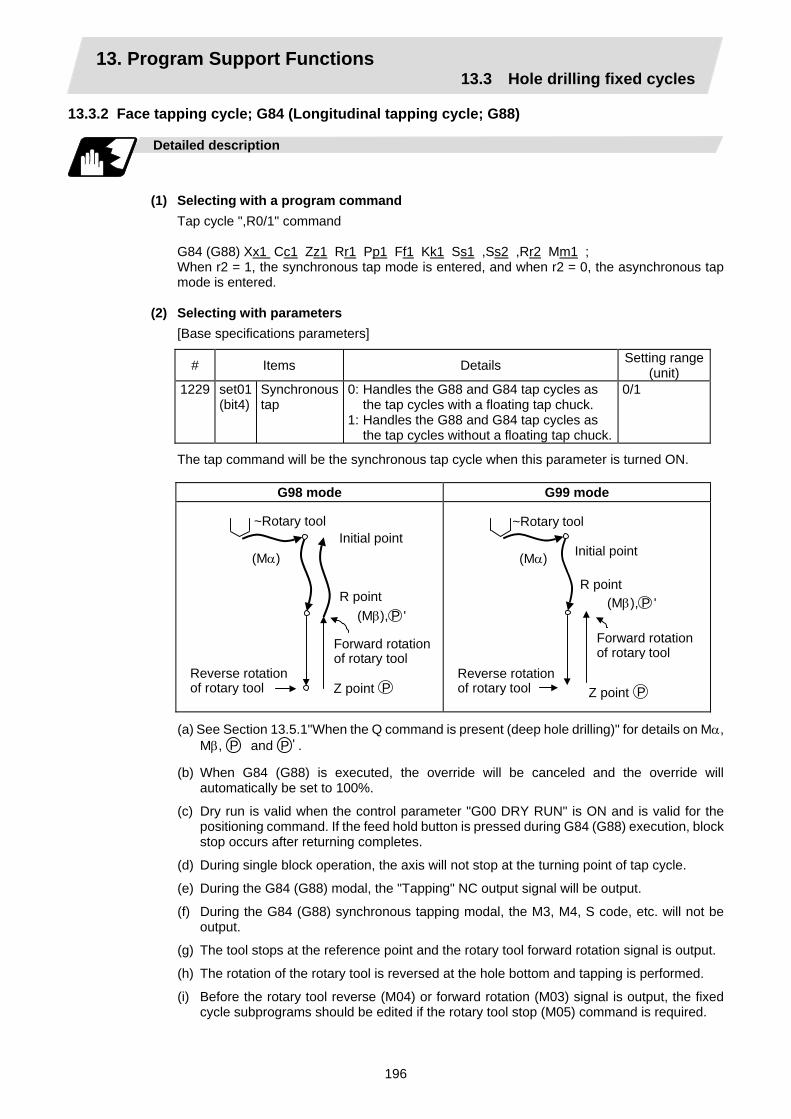
13. Program Support Functions 13.3 Hole drilling fixed cycles
196
13.3.2 Face tapping cycle; G84 (Longitudinal tapping cycle; G88)
Detailed description
(1) Selecting with a program command
Tap cycle ",R0/1" command
G84 (G88) Xx1 Cc1 Zz1 Rr1 Pp1 Ff1 Kk1 Ss1 ,Ss2 ,Rr2 Mm1 ; When r2 = 1, the synchronous tap mode is entered, and when r2 = 0, the asynchronous tap mode is entered.
(2) Selecting with parameters [Base specifications parameters]
# Items Details Setting range(unit)
1229 set01 (bit4)
Synchronous tap
0: Handles the G88 and G84 tap cycles as the tap cycles with a floating tap chuck.
1: Handles the G88 and G84 tap cycles as the tap cycles without a floating tap chuck.
0/1
The tap command will be the synchronous tap cycle when this parameter is turned ON.
G98 mode G99 mode
Initial point
R point
Z point
(Mα)
P
(Mβ), P '
~Rotary tool
Forward rotationof rotary tool
Reverse rotation of rotary tool
Initial point
R point
Z point
(Mα)
P
(Mβ), P '
~Rotary tool
Forward rotationof rotary tool
Reverse rotationof rotary tool
(a) See Section 13.5.1"When the Q command is present (deep hole drilling)" for details on Mα, Mβ, P and P ' .
(b) When G84 (G88) is executed, the override will be canceled and the override will automatically be set to 100%.
(c) Dry run is valid when the control parameter "G00 DRY RUN" is ON and is valid for the positioning command. If the feed hold button is pressed during G84 (G88) execution, block stop occurs after returning completes.
(d) During single block operation, the axis will not stop at the turning point of tap cycle.
(e) During the G84 (G88) modal, the "Tapping" NC output signal will be output.
(f) During the G84 (G88) synchronous tapping modal, the M3, M4, S code, etc. will not be output.
(g) The tool stops at the reference point and the rotary tool forward rotation signal is output.
(h) The rotation of the rotary tool is reversed at the hole bottom and tapping is performed.
(i) Before the rotary tool reverse (M04) or forward rotation (M03) signal is output, the fixed cycle subprograms should be edited if the rotary tool stop (M05) command is required.

13. Program Support Functions 13.3 Hole drilling fixed cycles
197
Canceling synchronous tap selection
The synchronous tap selection is canceled when the reset, G80 (hole drilling fixed cycle cancel), 01 group G code or other fixed cycle G code is commanded.
Spindle acceleration/deceleration pattern during synchronous tap
This function allows spindle acceleration/deceleration pattern to be approached to the speed loop acceleration/deceleration pattern by dividing the spindle and drilling axis acceleration/ deceleration pattern into up to three stages during synchronous tapping. The acceleration/deceleration pattern can be set up to three stages for each gear. When returning from the hole bottom, rapid return is possible depending on the spindle rotation speed during return. The spindle rotation speed during return is held as modal information.
(1) When tap rotation speed < spindle rotation speed during return ≤ synchronous tap changeover
spindle rotation speed 2
Smax S2
S(S1)
S1 S’ S2
Smax
T1
T1 T1
T1
T2
T2
S S' S1 S2 Smax T1 T2
: Command spindle rotation speed : Spindle rotation speed during return : Tap rotation speed (spindle base specification parameters #3013 to #3016) : Synchronous tap changeover spindle rotation speed 2
(spindle base specification parameters #3037 to #3040) : Maximum rotation speed (spindle base specification parameters #3005 to
#3008) : Tap time constant (spindle base specification parameters #3017 to #3020) : Synchronous tap changeover time constant 2
(spindle base specification parameters #3041 to #3044)

13. Program Support Functions 13.3 Hole drilling fixed cycles
198
(2) When synchronous tap changeover spindle rotation speed 2 < spindle rotation speed during return
Smax S2 S(S1)
S1S2
S'(Smax)
T1
T2T1T1
T1
T2
T3
T3
S S' S1 S2 Smax T1 T2 T3
: Command spindle rotation speed : Spindle rotation speed during return : Tap rotation speed (spindle base specification parameters #3013 to #3016) : Synchronous tap changeover spindle rotation speed 2
(spindle base specification parameters #3037 to #3040) : Maximum rotation speed (spindle base specification parameters #3005 to
#3008) : Tap time constant (spindle base specification parameters #3017 to #3020) : Synchronous tap changeover time constant 2
(spindle base specification parameters #3041 to #3044) : Synchronous tap changeover time constant 3
(spindle base specification parameters #3045 to #3048)

13. Program Support Functions 13.3 Hole drilling fixed cycles
199
13.3.3 Face boring cycle; G85 (Longitudinal boring cycle; G89)
Detailed description
G85 (G89) X (z)_ C_ Z (x)_ R_ P_ F_ K_ M_ ;
G98 mode G99 mode
2f f
Initial point
R point
Z point
(Mα)
P
(Mβ), P '
2f f
Initial point
R point
Z point P
(Mβ), P '
(1) See Section 13.5.1 "When the Q command is present (deep hole drilling)" for details on Mα, Mβ, P and P ' .
(2) The tool returns to the R point at a cutting feedrate which is double the designated feedrate command. However, it does not exceed the maximum cutting feedrate.
13.3.4 Deep hole drilling cycle 2; G83.2
Function and purpose
The deep hole drilling cycle 2 drills deep holes in the X-axis or Z-axis direction by commanding the X or Z coordinate of the end point and the cut amount with cutting feed.
Command format
G83.2 W/Z/U/X R I K A Q J F ; W/Z/U/X Incremental value from hole drilling start point/coordinates of hole bottom (with
sign) R Incremental value (sign ignored) from present position up to hole drilling start
point, always radius value with incremental value. I Cut amount of first cutting pass (sign ignored), always radius value with
incremental value. K Cut amount of second and subsequent cutting passes (sign ignored), always
radial value with incremental value. A Drill stop safety distance for second and subsequent cutting passes (sign
ignored), always radial value with incremental value. Q Dwell time at cut point (sign ignored, decimal point invalid) J Dwell time at return point (sign ignored, decimal point invalid) F Cutting feedrate

13. Program Support Functions 13.3 Hole drilling fixed cycles
200
Operation
Dwell QDwell J
No dwell J
(For Z-axis direction)
A K
Z RI
G1 G0G0
W
A A AK K
Example of program (when deep hole drilling cycle 2 is used as a modal command)
G28 XZ ; G0 X0. Z0. ;................................................................................................................. (1) G83.2 Z110. R20. I30. K20. A5. Q1000 J500. F300. ; ............................................... (2) X100. ;......................................................................................................................... (3) X50. ;........................................................................................................................... (4) M02 ;
Operation
Movement as far as X50.
X
100.
50.
20. 50. 70. 90. 110.(1)
Movement as far as X100.
(3) Hole drilling
(4) Hole drilling
(2) Hole drilling Z

13. Program Support Functions 13.3 Hole drilling fixed cycles
201
Detailed description
(1) When the drill stop safety distance (address "A") command is not given, the parameter #8013
return parameter setting value is used.
(2) The deep hole drilling cycle 2 is a modal command and so it will remain valid until a command in the same modal group or the cancel command (G80) is issued.
(3) If the command either for the cut amount (address "I") for the first cutting pass or the cut amount (address "K") for the second and subsequent passes is not present (including a command value of zero), the command value which is present will be used and the operation will be executed with both I and K equal to the command value.
If both commands are not present, hole drilling is conducted once as far as the hole bottom.
(4) When the axis address of the hole drilling axes has been commanded a multiple number of times in a block, the address commanded last is valid.
(5) The deep hole drilling fixed cycle 2 is also canceled by any G code in the 01 group except G80. If it is commanded in the same block as the fixed cycle, the fixed cycle will be ignored.
m = 01 group code, n = hole drilling fixed cycle code
(a) Gm Gn X(z)__ C__ Z(x)__ R__ I__ K__ A__ Q__ J__ F__ ;
(b) Gn Gm X(z)__ C__ Z(x)__ R__ I__ K__ A__ Q__ J__ F__ ;
(Examples) G01 G83.2 Z50. R−10. I8. K10. A3. Q1000 J500 F100. ; G83.2 G01 Z50. R−10. I8. K10. A3. Q1000 J500 F100. ; In both cases, G01 Z50. F100. is executed.
(6) When a miscellaneous command is issued in the same block as the deep hole drilling cycle 2
command, it is output at the same time as the initial positioning.
(7) When a tool length offset command (T function) is issued in the deep hole drilling cycle 2 mode, execution will follow the tool length offset function.
(8) If the basic axis, additional axis or R data are in the block during the deep hole drilling cycle 2 mode, hole drilling is performed; if the data are not present, no holes are machined.
Even if the X-axis data are present, no holes will be machined if the dwell (G04) time command is present in the block.
(9) Command the hole machining data (A, I, K, Q, J) in the block (including the basic axis, additional axis or R data) in which the hole drilling operation is conducted.
Even if they are commanded in a block with no hole drilling operation, the modal data will not be updated.
(10) A program error (P33) results with the following commands.
(a) When both the X hole drilling axis (command address X or U) and the Z hole drilling axis (command address Z or W) have been commanded.
(b) When any axis except X or Z (any command address except X, U, Z and W) has been commanded.
Executed Ignored Executed Ignored Memorized
Ignored Executed Ignored Memorized
13. Program Support Functions 13.3 Hole drilling fixed cycles
202
(11) When the feed hold button is pressed while the deep hole drilling cycle 2 is being executed, feed hold results at that point, and when automatic operation is restarted, the remainder is executed.
(12) When an interrupt based on manual operation is performed during the feed hold (manual absolute switch ON), the operation in the deep hole drilling cycle 2 modal is shifted from the automatic operation restart by an amount equivalent to the movement caused by the interrupt.
(13) With single block operation, block stop results upon completion of the deep hole drilling cycle 2 command.
13.3.5 Hole drilling fixed cycle cancel; G80
Detailed description
This cancels the hole drilling fixed cycle (G83, G84, G85, G87, G88, G89). The hole machining mode and hole machining data are both canceled.
13.3.6 Precautions when using a hole drilling fixed cycle
Precautions
(1) When a G84 or G88 fixed cycle is commanded, the rotary tool must be rotated in the specified
direction beforehand by the previous miscellaneous functions (M3, M4).
(2) If there is data for the basic axis, additional axis or R in the same block during fixed cycle mode, hole drilling is carried out. If there is no data, the hole drilling is not carried out. Note that even with X axis data, if that block is a dwell (G04) time command, the hole drilling is not carried out.
(3) Command hole machining data (Q, P) in the block in which hole drilling is carried out (block containing data for the basic axis, additional axis or R).
The modal data is not updated in blocks without hole drilling, even if these data are commanded.
(4) The F modal may change when a reset is applied during execution of G85 (G89).
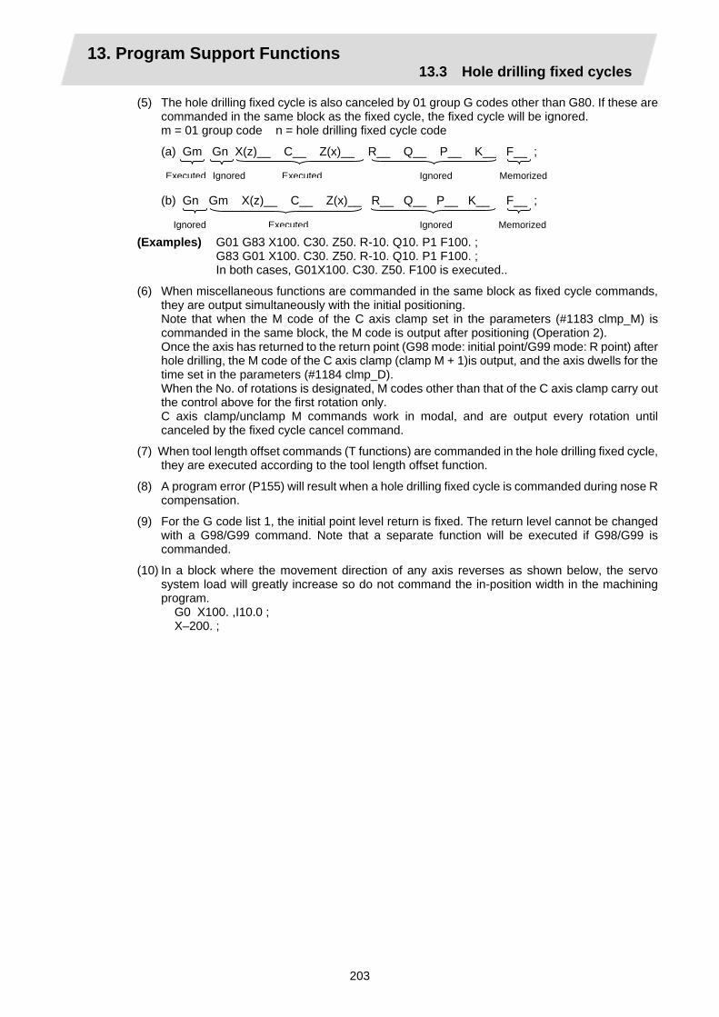
13. Program Support Functions 13.3 Hole drilling fixed cycles
203
(5) The hole drilling fixed cycle is also canceled by 01 group G codes other than G80. If these are commanded in the same block as the fixed cycle, the fixed cycle will be ignored. m = 01 group code n = hole drilling fixed cycle code
(a) Gm Gn X(z)__ C__ Z(x)__ R__ Q__ P__ K__ F__ ;
(b) Gn Gm X(z)__ C__ Z(x)__ R__ Q__ P__ K__ F__ ; (Examples) G01 G83 X100. C30. Z50. R-10. Q10. P1 F100. ; G83 G01 X100. C30. Z50. R-10. Q10. P1 F100. ; In both cases, G01X100. C30. Z50. F100 is executed..
(6) When miscellaneous functions are commanded in the same block as fixed cycle commands, they are output simultaneously with the initial positioning.
Note that when the M code of the C axis clamp set in the parameters (#1183 clmp_M) is commanded in the same block, the M code is output after positioning (Operation 2).
Once the axis has returned to the return point (G98 mode: initial point/G99 mode: R point) after hole drilling, the M code of the C axis clamp (clamp M + 1)is output, and the axis dwells for the time set in the parameters (#1184 clmp_D).
When the No. of rotations is designated, M codes other than that of the C axis clamp carry out the control above for the first rotation only.
C axis clamp/unclamp M commands work in modal, and are output every rotation until canceled by the fixed cycle cancel command.
(7) When tool length offset commands (T functions) are commanded in the hole drilling fixed cycle, they are executed according to the tool length offset function.
(8) A program error (P155) will result when a hole drilling fixed cycle is commanded during nose R compensation.
(9) For the G code list 1, the initial point level return is fixed. The return level cannot be changed with a G98/G99 command. Note that a separate function will be executed if G98/G99 is commanded.
(10) In a block where the movement direction of any axis reverses as shown below, the servo system load will greatly increase so do not command the in-position width in the machining program. G0 X100. ,I10.0 ; X–200. ;
Executed Ignored Executed Ignored Memorized
Ignored Executed Ignored Memorized

13. Program Support Functions 13.4 Subprogram control
204
13.4 Subprogram control; M98, M99 13.4.1 Calling subprogram with M98 and M99 commands
Function and purpose
Fixed sequences or repeatedly used parameters can be stored in the memory as subprograms which can then be called from the main program when required. M98 serves to call subprograms and M99 serves to return operation from the subprogram to the main program. Furthermore, it is possible to call other subprograms from particular subprograms and the nesting depth can include as many as 8 levels.
Main programO0010; M98 P1000; M02;
Subprogram O1000; M98 P1200
H20; M99;
(Level 1)
Subprogram O1200; N20; M98 P2000; N60; M99;
Subprogram O2000; M98 P2500; M99 P60;
Subprogram O2500; M99;
(Level 2) (Level 3) (Level 4)
Nesting depth
The table below shows the functions which can be executed by adding and combining the subprogram control functions and fixed cycle functions.
Case 1 Case 2 Case 3 Case 41. Subprogram control No Yes Yes No 2. Fixed cycles No No Yes Yes
Function 1. Memory operation 2. Subprogram call × × 3. Subprogram variable designation (Note 2) × × 4. Subprogram nesting level call (Note 3) × × 5. Fixed cycles × × 6. Subprogram editing for fixed cycle × ×
(Note 1) " " denotes a function which can be used and "×" a function which cannot be used.
(Note 2) Variables cannot be transferred with the M98 command but variable commands in subprograms can be used provided that the variable command option is available.
(Note 3) A maximum of 8 nesting levels form the nesting depth.

13. Program Support Functions 13.4 Subprogram control
205
Command format
Subprogram call
M98 P H L ; M98 Subprogram call command P_ Program number of subprogram to be called (own program if omitted)
P can be omitted only during memory operation and MDI operation. (Max. 8 digits)
H_ Sequence number in subprogram to be called (head block if omitted) (Max. 5 digits)
L_ Number of subprogram repetitions (When omitted, this is interpreted at L1, and is not executed when L0.) (Between 1 and 9999 times according to 4-digit value.) For instance, M98 P1 L3 ; is equivalent to the following: M98 P1 ; M98 P1 ; M98 P1 ;
Return to main program from subprogram
M99 P H Q R L ; M99 Subprogram return command P_ Sequence number of return destination (return to the block that following the
calling block if omitted) H_ Program number of return destination (return to the main program at calling if
omitted) Q_ Sequence number to start searching of return destination (the block that
follows the calling block will be handled as the search start position if omitted)R_ Sequence number to finish searching of return destination (the block that
precedes the calling block will be handled as the search finish position if omitted)
L_ Number of times after repetition number has been changed ("-1" if omitted)
Creating and entering subprograms
Subprograms have the same format as machining programs for normal memory operation except that the subprogram completion instruction M99 (P_ L_ ) ; is entered as an independent block at the last block.
∆∆∆∆∆∆∆∆ ; Program number as subprogram number ................................ ; ................................ ; : Main body of subprogram : : ................................ ; M99 ; Subprogram return command % (EOR) Entry completion code
(1) The above program is entered by editing operations at the setting and display unit. For further details, refer to the section on program editing in the Instruction Manual.
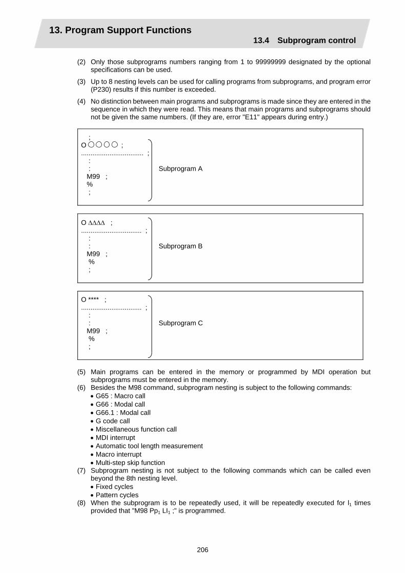
13. Program Support Functions 13.4 Subprogram control
206
(2) Only those subprograms numbers ranging from 1 to 99999999 designated by the optional specifications can be used.
(3) Up to 8 nesting levels can be used for calling programs from subprograms, and program error (P230) results if this number is exceeded.
(4) No distinction between main programs and subprograms is made since they are entered in the sequence in which they were read. This means that main programs and subprograms should not be given the same numbers. (If they are, error "E11" appears during entry.)
; O ; ................................. ; : : Subprogram A M99 ; % ;
O ∆∆∆∆ ; ................................ ; : : Subprogram B M99 ; % ;
O **** ; ................................ ; : : Subprogram C M99 ; % ;
(5) Main programs can be entered in the memory or programmed by MDI operation but
subprograms must be entered in the memory. (6) Besides the M98 command, subprogram nesting is subject to the following commands:
• G65 : Macro call • G66 : Modal call • G66.1 : Modal call • G code call • Miscellaneous function call • MDI interrupt • Automatic tool length measurement • Macro interrupt • Multi-step skip function
(7) Subprogram nesting is not subject to the following commands which can be called even beyond the 8th nesting level. • Fixed cycles • Pattern cycles
(8) When the subprogram is to be repeatedly used, it will be repeatedly executed for l1 times provided that "M98 Pp1 LI1 ;" is programmed.

13. Program Support Functions 13.4 Subprogram control
207
Example of program 1
When there are 3 subprogram calls (known as 3 nesting levels)
M98P1;
M02;
Main program Subprogram 1 Subprogram 2 Subprogram 3
Sequence of execution : (1) → (2) → (3) → (3)’ → (2)’ → (1)’
(1)
O1; M98P10;
M99;
O10; M98P20;
M99;
O20;
M99;
(1)’
(2)
(2)’
(3)
(3)’
(1) For nesting, the M98 and M99 commands should always be paired off on a 1:1 basis (1)’ for (1), (2)' for (2), etc.
(2) Modal information can be rewritten according to the execution sequence without distinction between main programs and subprograms. This means that after calling a subprogram, attention must be paid to the modal data status when programming.
Example of program 2
The "M98 H_ ;" and "M99 P_ ;" commands designate the sequence numbers in a program with a call instruction.
M98H3;
N3___;
M99;
M98H__ ;
N100___;
M98P123; N200_; N300___; N400___;
O123; M99P200;
M99P__ ;
Sea
rch

13. Program Support Functions 13.4 Subprogram control
208
Precautions
(1) Program error (P232) results when the designated P (program number) is not located.
(2) Single block stop does not occur with the "M98 P_ ; M99 ;" block. If any address except O, N, P, L or H is used, single block stop can be executed. (With "X100. M98 P100 ;", operation branches to O100 after "X100." is executed.)
(3) When M99 is commanded by the main program, operation returns to the head. (This is same for MDI.)
(4) Branching from BTR operation to the subprogram with M98 P_ is possible, but the return destination sequence No. cannot be designated with "M99 P_ ;". (P_ is ignored).
(5) Bear in mind that the search operation will take time when the sequence number is designated by "M99 P_ ;".

13. Program Support Functions 13.5 Variable commands
209
13.5 Variable commands
Function and purpose
Programming can be endowed with flexibility and general-purpose capabilities by designating variables, instead of giving direct numerical values to particular addresses in a program, and by assigning the values or those variables as required when executing a program.
Command format
#∆∆∆ = or #∆∆∆ = [formula]
Detailed description
(1) Variable expressions Example
(a) #m ............. m = value consisting of 0~9 #100
(b) # [f] ............. f = one of the following in the formula # [− #120] Numerical value m 123 Variable #543 Formula Operator Formula #110 + #119 − (minus) formula − # 120 [Formula] [#119] Function [formula] SIN [#110]
(Note 1) The 4 standard operators are +, −, ∗ and / .
(Note 2) Functions cannot be used unless the user macro specifications are available.
(Note 3) Error (P241) results when a variable number is negative.
(Note 4) Examples of incorrect variable expressions are given below.
Incorrect Correct #6/2 → # [6/2] (Note that expression such as "#6/2" is regarded as
"[#6]/2".)] # − − 5 → # [ − [ −5 ] ] # − [# 1] → # [ − #1 ]
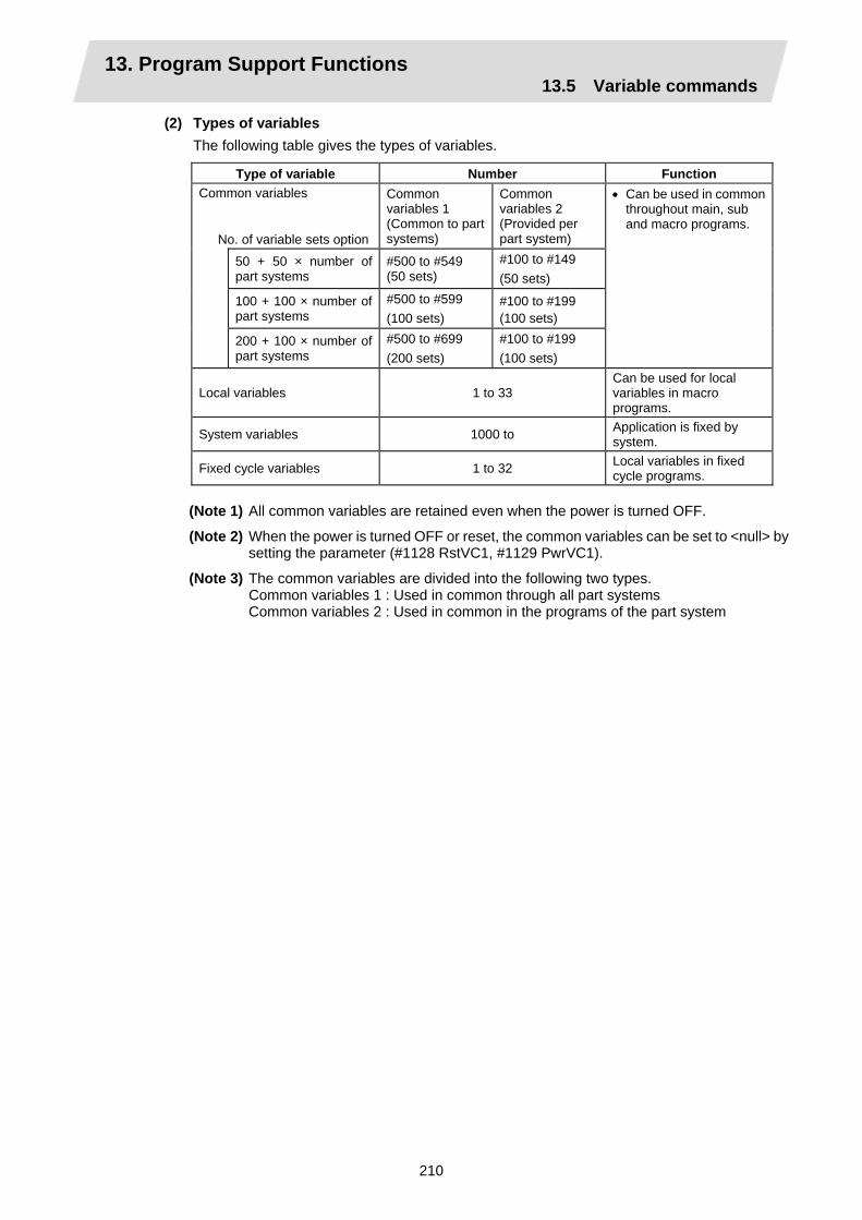
13. Program Support Functions 13.5 Variable commands
210
(2) Types of variables The following table gives the types of variables.
Type of variable Number Function Common variables
No. of variable sets option
Common variables 1 (Common to part systems)
Common variables 2 (Provided per part system)
50 + 50 × number of part systems
#500 to #549 (50 sets)
#100 to #149 (50 sets)
100 + 100 × number of part systems
#500 to #599 (100 sets)
#100 to #199 (100 sets)
200 + 100 × number of part systems
#500 to #699 (200 sets)
#100 to #199 (100 sets)
• Can be used in common throughout main, sub and macro programs.
Local variables 1 to 33 Can be used for local variables in macro programs.
System variables 1000 to Application is fixed by system.
Fixed cycle variables 1 to 32 Local variables in fixed cycle programs.
(Note 1) All common variables are retained even when the power is turned OFF.
(Note 2) When the power is turned OFF or reset, the common variables can be set to <null> by setting the parameter (#1128 RstVC1, #1129 PwrVC1).
(Note 3) The common variables are divided into the following two types. Common variables 1 : Used in common through all part systems Common variables 2 : Used in common in the programs of the part system

13. Program Support Functions 13.5 Variable commands
211
(3) Variable quotations Variables can be used for all addresses accept O, N and / (slash).
(a) When the variable value is used directly: X#1................................. Value of #1 is used as the X value.
(b) When the complement of the variable value is used: X−#2............................... Value with the #2 sign changed is used as the X value.
(c) When defining variables: #3 = #5........................... Variable #3 uses the equivalent value of variable #5. #1 = 1000....................... Variable #1 uses the equivalent value 1000 (which is treated as
1000.).
(d) When defining the variable arithmetic formula: #1 = #3 + #2 − 100......... The value of the operation result of #3 + #2 − 100. is used as the
#1 value. X [#1 + #3 + 1000] ......... The value of the operation result of #1 + #3 + 1000 is used as
the X value.
(Note 1) A variable cannot be defined in the same block as an address. It must be defined in a separate block.
Incorrect Correct X #1= #3 + 100 ; → #1= #3 + 100 ;
X#1 ;
(Note 2) Up to five sets of square parentheses [ ] may be used.
#543 = − [ [ [ [ [ #120]/2 + 15.]∗3 − #100]/#520 + #125 + #128]∗#130 + #132] ;
(Note 3) There are no restrictions on the number of characters and number of variables for variable definition.
(Note 4) The variable values should be within a range from 0 to ±99999999. If this range is exceeded, the operations may not be conducted properly.
(Note 5) The variable definitions are valid from the moment that the variables are actually defined.
#1 = 100 ; ............................. #1 = 100 #1 = 200 #2 = #1 + 200 ;...... #1 = 200, #2 = 400 #3 = #1 + 300 ;..................... #3 = 500
(Note 6) Variable quotations are always regarded as having a decimal point at the end.
When #100 = 10, then X#100 ; is treated as X10.

13. Program Support Functions 13.6 User macro
212
13.6 User macro 13.6.1 User macro commands; G65, G66, G66.1, G67
Function and purpose
By combining the user macros with variable commands, it is possible to use macro program call, operation, data input/output with PLC, control, decision, branch and many other instructions for measurement and other such applications.
; M99 ;
; M30 ;
O Main program O Macro program
Macro call instruction
……. …….
Macro programs use variables, operation instructions and control instructions to create subprograms which function to provide dedicated control. These dedicated control functions (macro programs) are called by the macro call instructions exactly when required from the main program.
G code Function G65 User macro Simple call G66 User macro Modal call A (called after the movement command) G66.1 User macro Modal call B (called after every block) G67 User macro Modal call cancel
Detailed description
(1) When the G66 or G66.1 command is entered, the specified user macro program will be called
after each block has been executed or after the movement command in the block with the movement commands has been executed until the G67 (cancel) command is entered.
(2) The G66 (G66.1) and G67 commands must be paired in the same program.

13. Program Support Functions 13.6 User macro
213
13.6.2 Macro call instruction
Function and purpose
Included among the macro call commands are the simple calls which apply only to the instructed block and also modal calls (types A and B) which apply to each block in the call modal.
Simple macro calls
M99 is used to conclude the user macro subprogram.
Format
M98 P__ L__ <argument> ;
P_ Program No. L_ No. of repetitions
When the <argument> must be transferred as a local variable to a user macro subprogram, the actual value should be designated after the address. Regardless of the address, a sign and decimal point can be used in the argument. There are 2 ways in which arguments are designated. (1) Argument designation I
Format : A_ B_ C_ ... X_ Y_ Z_
Detailed description (a) Arguments can be designated using any address except G, L, N, O and P.
(b) Except for I, J and K, there is no need for designation in alphabetical order.
(c) I, J and K must be designated in alphabetical order.
I_ J_ K_ ...... Correct J_ I_ K_ ...... Incorrect
(d) Addresses which do not need to be designated can be omitted.
(e) The following table shows the correspondence between the addresses which can be designated by argument designation I and the variable numbers in the user macro main body.
O o1 M99
~
To subprogram
To main program
Main program Subprogram (Oo1)
G65Pp1Ll1 <argument> ;
~ ~
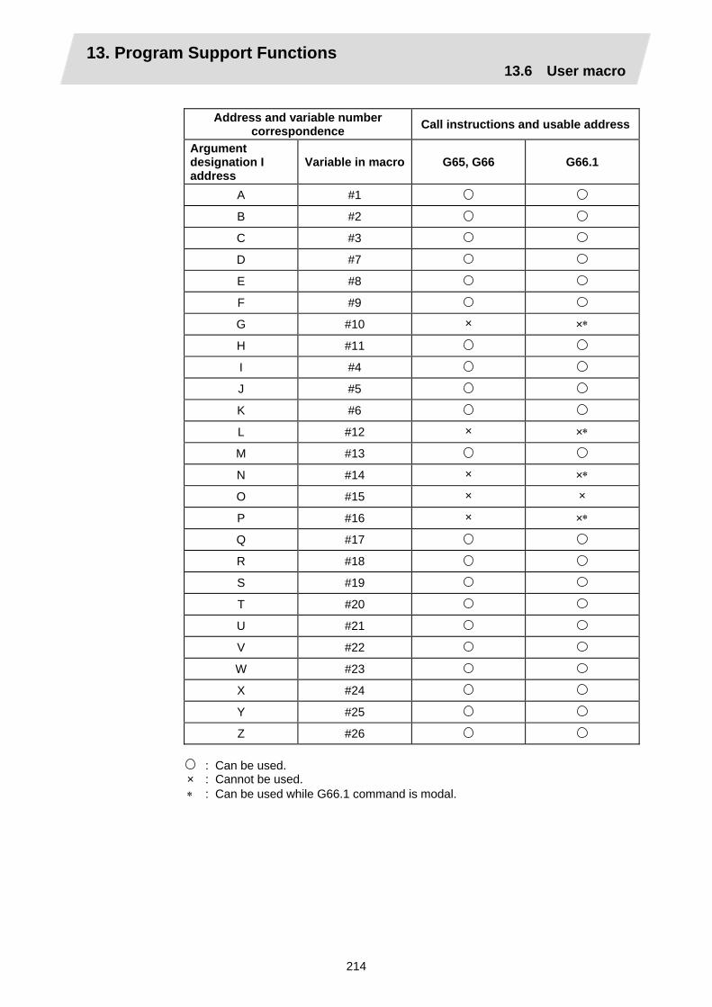
13. Program Support Functions 13.6 User macro
214
Address and variable number
correspondence Call instructions and usable address
Argument designation I address
Variable in macro G65, G66 G66.1
A #1 B #2 C #3 D #7 E #8 F #9 G #10 × ×∗ H #11 I #4 J #5 K #6 L #12 × ×∗ M #13 N #14 × ×∗ O #15 × × P #16 × ×∗ Q #17 R #18 S #19 T #20 U #21 V #22 W #23 X #24 Y #25 Z #26
: Can be used. × : Cannot be used. ∗ : Can be used while G66.1 command is modal.

13. Program Support Functions 13.6 User macro
215
(2) Argument designation II Format : A_ B_ C_ I_ J_ K_ I_ J_ K_ ...
Detailed description (a) In addition to addresses A, B and C, up to 10 groups of arguments with I, J, K serving as 1
group can be designated. (b) When the same address is duplicated, designate the addresses in the specified order. (c) Addresses which do not need to be designated can be omitted. (d) The following table shows the correspondence between the addresses which can be
designated by argument designation II and the variable numbers in the user macro main body.
Argument designation II address
Variable within macro
Argument designation II address
Variable within macro
A #1 J5 #17 B #2 K5 #18 C #3 I6 #19 I1 #4 J6 #20 J1 #5 K6 #21 K1 #6 I7 #22 I2 #7 J7 #23 J2 #8 K7 #24 K2 #9 I8 #25 I3 #10 J8 #26 J3 #11 K8 #27 K3 #12 I9 #28 I4 #13 J9 #29 J4 #14 K9 #30 K4 #15 I10 #31 I5 #16 J10 #32 K10 #33
(Note 1) The numbers 1 to 10 accompanying I, J and K denote the sequence of the
commanded groups and they are not required for the actual instructions.
(3) Using arguments designations I and II together If addresses corresponding to the same variable are commanded when both types I and II are used to designate arguments, the latter address is valid.
(Example 1)
Call instruction G65 A1.1 B–2.2 D3.3 I4.4 I7.7 ; Variable
#1 : 1.1 #2 : –2.2 #3 : #4 : 4.4 #5 : #6 : #7 : 3.3 7.7
In the above example the last I7.7 argument is valid when both arguments D3.3 and I7.7 are commanded for the #7 variable.
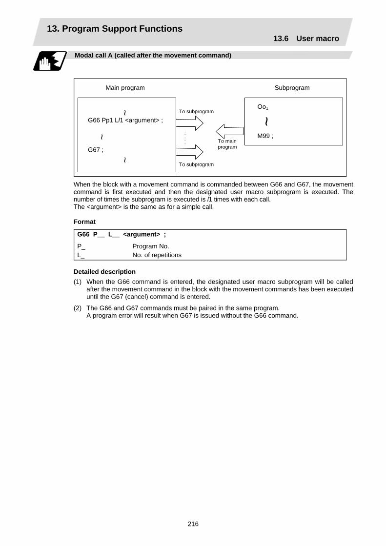
13. Program Support Functions 13.6 User macro
216
Modal call A (called after the movement command)
Oo1 M99 ; ~
~
To subprogram
To main program
Main program Subprogram
G66 Pp1 Ll1 <argument> ; ~
G67 ;
~ To subprogram
:::
When the block with a movement command is commanded between G66 and G67, the movement command is first executed and then the designated user macro subprogram is executed. The number of times the subprogram is executed is l1 times with each call. The <argument> is the same as for a simple call.
Format
G66 P__ L__ <argument> ;
P_ Program No. L_ No. of repetitions
Detailed description (1) When the G66 command is entered, the designated user macro subprogram will be called
after the movement command in the block with the movement commands has been executed until the G67 (cancel) command is entered.
(2) The G66 and G67 commands must be paired in the same program. A program error will result when G67 is issued without the G66 command.
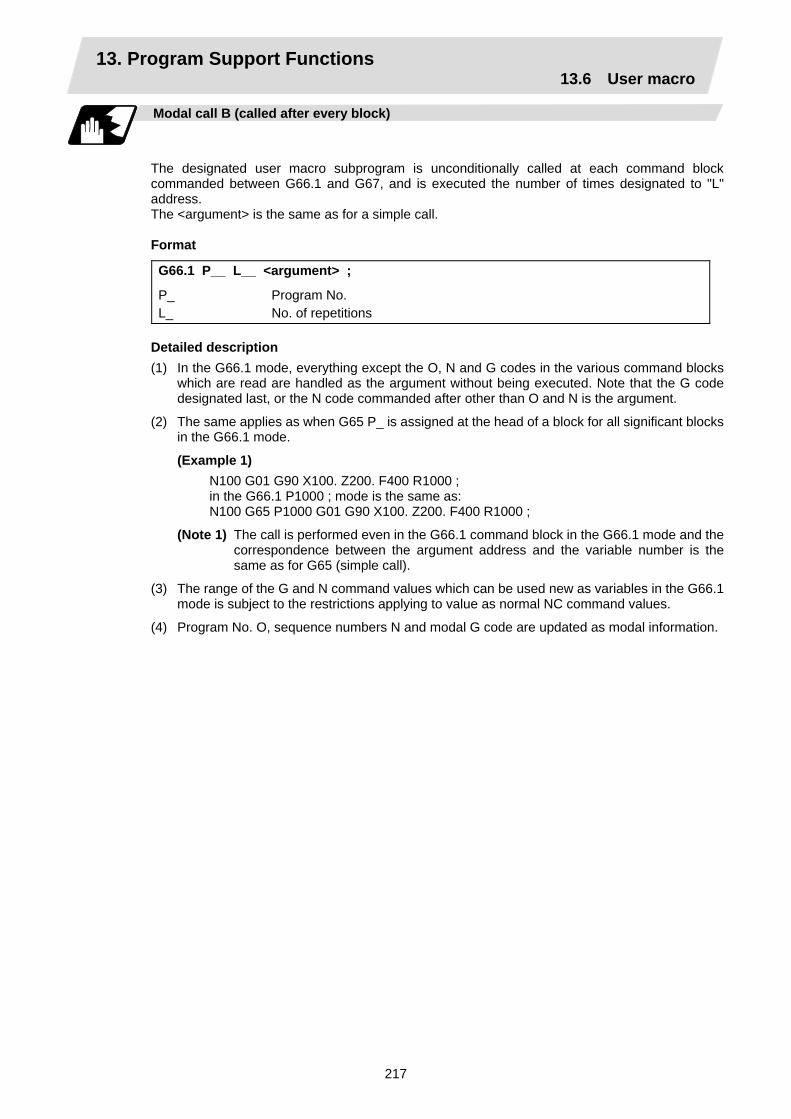
13. Program Support Functions 13.6 User macro
217
Modal call B (called after every block)
The designated user macro subprogram is unconditionally called at each command block commanded between G66.1 and G67, and is executed the number of times designated to "L" address. The <argument> is the same as for a simple call. Format
G66.1 P__ L__ <argument> ;
P_ Program No. L_ No. of repetitions
Detailed description (1) In the G66.1 mode, everything except the O, N and G codes in the various command blocks
which are read are handled as the argument without being executed. Note that the G code designated last, or the N code commanded after other than O and N is the argument.
(2) The same applies as when G65 P_ is assigned at the head of a block for all significant blocks in the G66.1 mode.
(Example 1) N100 G01 G90 X100. Z200. F400 R1000 ; in the G66.1 P1000 ; mode is the same as: N100 G65 P1000 G01 G90 X100. Z200. F400 R1000 ;
(Note 1) The call is performed even in the G66.1 command block in the G66.1 mode and the correspondence between the argument address and the variable number is the same as for G65 (simple call).
(3) The range of the G and N command values which can be used new as variables in the G66.1 mode is subject to the restrictions applying to value as normal NC command values.
(4) Program No. O, sequence numbers N and modal G code are updated as modal information.
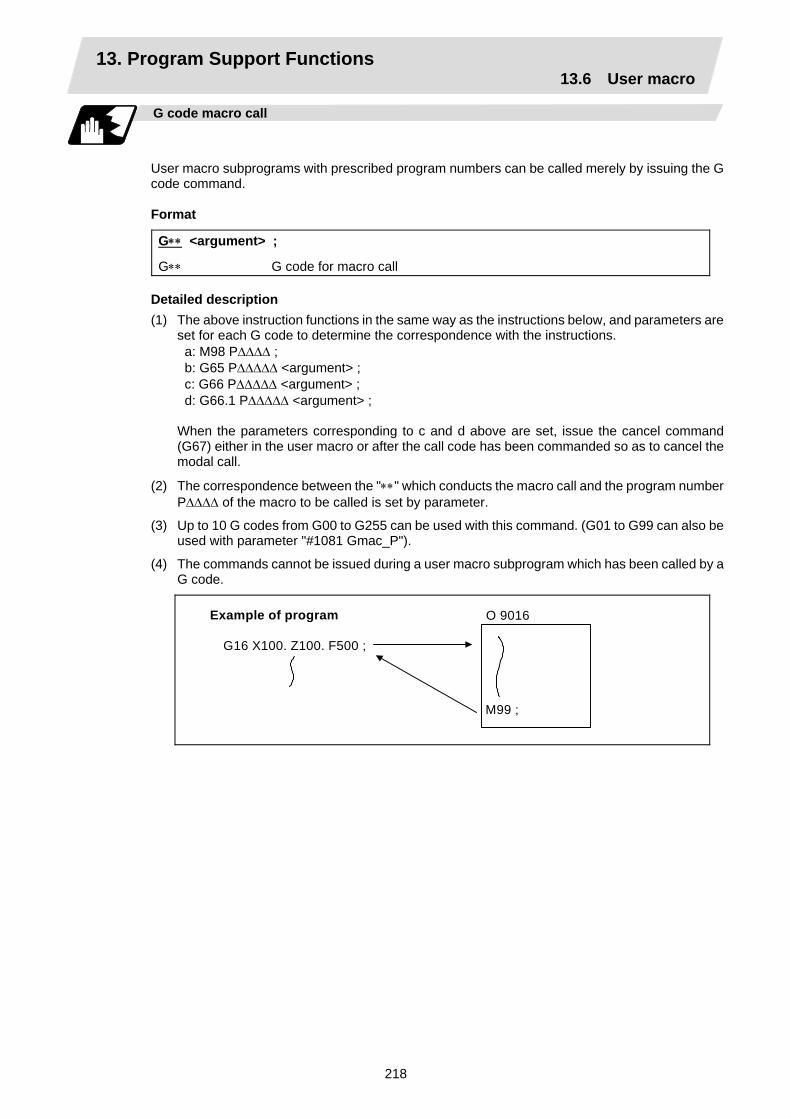
13. Program Support Functions 13.6 User macro
218
G code macro call
User macro subprograms with prescribed program numbers can be called merely by issuing the G code command.
Format
G∗∗ <argument> ;
G∗∗ G code for macro call Detailed description (1) The above instruction functions in the same way as the instructions below, and parameters are
set for each G code to determine the correspondence with the instructions. a: M98 P∆∆∆∆ ; b: G65 P∆∆∆∆∆ <argument> ; c: G66 P∆∆∆∆∆ <argument> ; d: G66.1 P∆∆∆∆∆ <argument> ;
When the parameters corresponding to c and d above are set, issue the cancel command (G67) either in the user macro or after the call code has been commanded so as to cancel the modal call.
(2) The correspondence between the "∗∗" which conducts the macro call and the program number P∆∆∆∆ of the macro to be called is set by parameter.
(3) Up to 10 G codes from G00 to G255 can be used with this command. (G01 to G99 can also be used with parameter "#1081 Gmac_P").
(4) The commands cannot be issued during a user macro subprogram which has been called by a G code.
Example of program
G16 X100. Z100. F500 ; M99 ;
O 9016
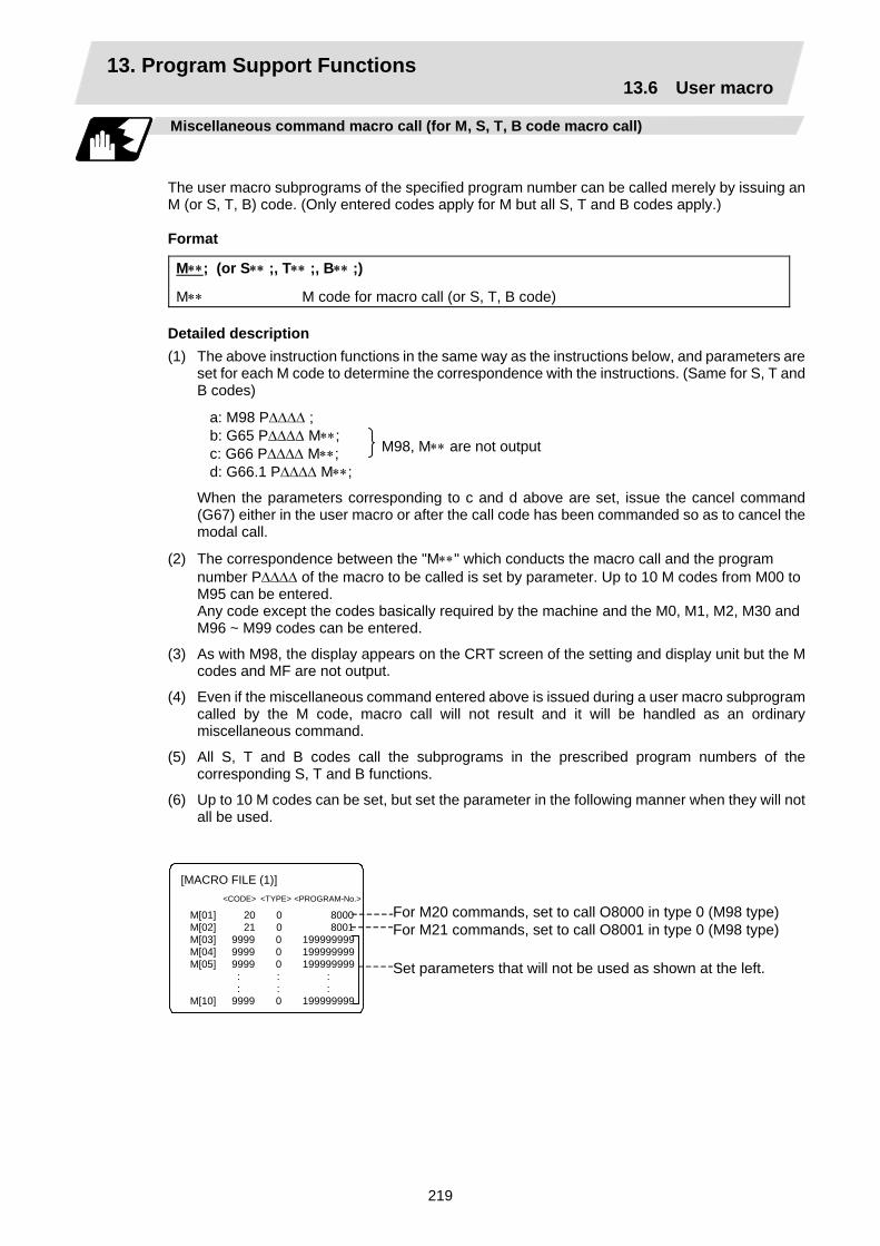
13. Program Support Functions 13.6 User macro
219
Miscellaneous command macro call (for M, S, T, B code macro call)
The user macro subprograms of the specified program number can be called merely by issuing an M (or S, T, B) code. (Only entered codes apply for M but all S, T and B codes apply.)
Format
M∗∗; (or S∗∗ ;, T∗∗ ;, B∗∗ ;)
M∗∗ M code for macro call (or S, T, B code) Detailed description (1) The above instruction functions in the same way as the instructions below, and parameters are
set for each M code to determine the correspondence with the instructions. (Same for S, T and B codes)
a: M98 P∆∆∆∆ ; b: G65 P∆∆∆∆ M∗∗; c: G66 P∆∆∆∆ M∗∗; d: G66.1 P∆∆∆∆ M∗∗;
When the parameters corresponding to c and d above are set, issue the cancel command (G67) either in the user macro or after the call code has been commanded so as to cancel the modal call.
(2) The correspondence between the "M∗∗" which conducts the macro call and the program number P∆∆∆∆ of the macro to be called is set by parameter. Up to 10 M codes from M00 to M95 can be entered. Any code except the codes basically required by the machine and the M0, M1, M2, M30 and M96 ~ M99 codes can be entered.
(3) As with M98, the display appears on the CRT screen of the setting and display unit but the M codes and MF are not output.
(4) Even if the miscellaneous command entered above is issued during a user macro subprogram called by the M code, macro call will not result and it will be handled as an ordinary miscellaneous command.
(5) All S, T and B codes call the subprograms in the prescribed program numbers of the corresponding S, T and B functions.
(6) Up to 10 M codes can be set, but set the parameter in the following manner when they will not all be used.
M[01] 20 0 8000 M[02] 21 0 8001 M[03] 9999 0 199999999 M[04] 9999 0 199999999 M[05] 9999 0 199999999 : : : : : : M[10] 9999 0 199999999
For M20 commands, set to call O8000 in type 0 (M98 type)For M21 commands, set to call O8001 in type 0 (M98 type)
Set parameters that will not be used as shown at the left.
[MACRO FILE (1)] <CODE> <TYPE> <PROGRAM-No.>
M98, M∗∗ are not output
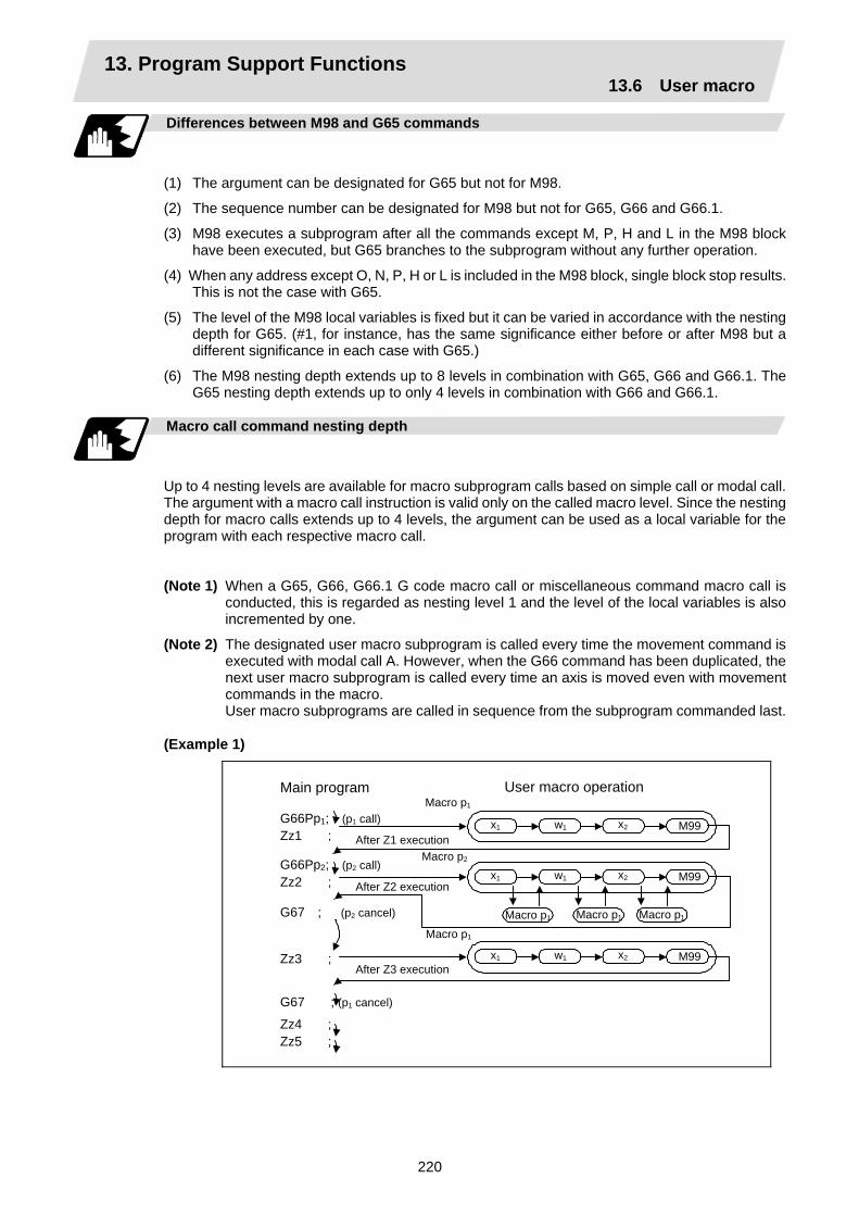
13. Program Support Functions 13.6 User macro
220
Differences between M98 and G65 commands
(1) The argument can be designated for G65 but not for M98.
(2) The sequence number can be designated for M98 but not for G65, G66 and G66.1.
(3) M98 executes a subprogram after all the commands except M, P, H and L in the M98 block have been executed, but G65 branches to the subprogram without any further operation.
(4) When any address except O, N, P, H or L is included in the M98 block, single block stop results. This is not the case with G65.
(5) The level of the M98 local variables is fixed but it can be varied in accordance with the nesting depth for G65. (#1, for instance, has the same significance either before or after M98 but a different significance in each case with G65.)
(6) The M98 nesting depth extends up to 8 levels in combination with G65, G66 and G66.1. The G65 nesting depth extends up to only 4 levels in combination with G66 and G66.1.
Macro call command nesting depth
Up to 4 nesting levels are available for macro subprogram calls based on simple call or modal call. The argument with a macro call instruction is valid only on the called macro level. Since the nesting depth for macro calls extends up to 4 levels, the argument can be used as a local variable for the program with each respective macro call.
(Note 1) When a G65, G66, G66.1 G code macro call or miscellaneous command macro call is
conducted, this is regarded as nesting level 1 and the level of the local variables is also incremented by one.
(Note 2) The designated user macro subprogram is called every time the movement command is executed with modal call A. However, when the G66 command has been duplicated, the next user macro subprogram is called every time an axis is moved even with movement commands in the macro.
User macro subprograms are called in sequence from the subprogram commanded last.
(Example 1)
Main program
G66Pp1; (p1 call) Zz1 ;
x1 w1 x2 M99
x1 w1 x2 M99
x1 w1 x2 M99
G66Pp2; (p2 call) Zz2 ;
G67 ; (p2 cancel)
Zz3 ;
G67 ; (p1 cancel)
Zz4 ; Zz5 ;
User macro operation Macro p1
Macro p2
Macro p1 Macro p1 Macro p1 Macro p1
After Z2 execution
After Z1 execution
After Z3 execution

13. Program Support Functions 13.6 User macro
221
13.6.3 Variables
Function and purpose
Both the variable specifications and user macro specifications are required for the variables which are used with the user macros. The offset amounts of the local, common and system variables among the variables for this NC unit are retained even when the unit's power is turned OFF. (Common variables can also be set to < Blank > in parameter "#1129 PwrVC1")
Use of multiple variable
When the user macro specifications apply, variable numbers can be turned into variables (multiple use of variables) or replaced by <formula>. Only one of the arithmetical (+, −, ×, ÷) operations can be conducted with <formula>.
(Example 1) Multiple use of variables
#1 = 10 #10 = 20 #20 = 30 ; # [# [#1] ] = # [#10] from #1 = 10. #5 = # [# [#1] ] ; # [#10] = #20 from #10 = 20. Therefore, #5 = #20 or #5 = 30.
#1 = 10 #10 = 20 #20 = 30 #5 = 1000 ; # [# [#1] ] = # [#10] from #1 = 10. # [# [#1]] = #5 ; # [#10] = #20 from #10 = 20. Therefore, #20 = #5 or #20 = 1000.
(Example 2) Replacing variable numbers with <formula>
#10 = 5 ; # [#10 + 1] = 1000 ; In which case, #6 = 1000. # [#10 − 1] = −1000 ; In which case, #4 = −1000. # [#10∗3] = 100 ; In which case, #15 = 100. # [#10/2] = −100 ; In which case, #3 = −100. (fraction rounded up)

13. Program Support Functions 13.6 User macro
222
Undefined variables
Variables applying with the user macro specifications such as variables which have not been used even once after the power was turned ON or local variables not quoted by the G65, G66 or G66.1 commands can be used as <Blank>. Also, variables can forcibly be set to <Blank>. Variable #0 is always used as the <Blank> variable and nothing can be defined in the left-side member.
(1) Arithmetic expressions
#1 = #0 ; ...........................#1 = <Blank> #2 = #0 + 1 ; .....................#2 = 1 #3 = 1 + #0 ; .....................#3 = 1 #4 = #0∗10 ; .....................#4 = 0 #5 = #0 + #0 ; ...................#5 = 0
(2) Variable quotations When undefined variable only are quoted, they are ignored up to the address.
When #1 = <Blank> G0 X#1 Z1000 ; ......................... Equivalent to G0 Z1000 ; G0 X#1 + 10 Z1000 ; ................. Equivalent to G0 X10 Z1000 ;
(3) Conditional expressions
<Blank> differs from "0" only for EQ and NE. (#0 is <Blank>.)
When #101 = <Blank> When #101 = 0 #101 EQ #0
<Blank> = <Blank> established #101 EQ #0
0 = <Blank> not established #101 NE 0
<Blank> ≠ 0 established #101 NE 0
0 ≠ 0 not established #101 GE #0
<Blank> ≥ 0 established #101 GE #0
0 ≥ <Blank> established #101 GT 0
<Blank> > 0 not established #101 GT 0
0 > 0 not established #101 LE #0
<Blank> ≤ <Blank> established #101 LE #0
0 ≤ <Blank> established #101 GT0
<Blank> < 0 not established #101 LT0
0 < 0 not established
(Note 1) Only compare EQ and NE by integers. Use GE, GT, LE and LT for comparison when there are numbers below the decimal point.
It should be borne in mind that <Blank> in an arithmetic expression is handled in the same way as 0. <Blank> + <Blank> = 0 <Blank> + <Constant> = Constant <Constant> + <Blank> = Constant

13. Program Support Functions 13.6 User macro
223
13.6.4 Types of variables
Common variables
These are the variables used commonly from a random position. The number of the common variables sets depends on the specifications. Refer to the explanation about Variables for details.
Local variables (#1 to #33)
These can be defined as an <argument> when a macro subprogram is called or used locally within main programs and subprograms. They can be duplicated regardless of the relationship existing between macros (up to 4 levels).
G65 Pp1 Ll1 <argument> ;
p1 Program number l1 Number of repetitions
The <argument> is assumed to be Aa1 Bb1 Cc1...... Zz1. The following table shows the correspondences between the addresses designated by <argument> and the local variable numbers used in the user macro main body. [Argument designation I]
Call command G65, G66 G66.1
Argument address
Local variable number
A #1B #2C #3D #7E #8F #9
× ×∗ G #10H #11I #4J #5K #6
× ×∗ L #12M #13
× ×∗ N #14× ×∗ O #15× ×∗ P #16
"×" in the above table denotes an argument address which cannot be used. However, provided that the G66.1 mode has been established, an argument address denoted by the asterisk can be added for use. The hyphen (–) mark indicates that there is no corresponding address.
Call commandG65, G66 G66.1
Argument address
Local variable number
Q #17R #18S #19T #20U #21V #22W #23X #24Y #25Z #26– #27– #28– #29– #30– #31– #32– #33

13. Program Support Functions 13.6 User macro
224
[Argument designation II]
Argument designation II
address Variable in macro
Argument designation II
address Variable in macro
A # 1 J5 #17 B # 2 K5 #18 C # 3 I6 #19 I1 # 4 J6 #20 J1 # 5 K6 #21 K1 # 6 I7 #22 I2 # 7 J7 #23 J2 # 8 K7 #24 K2 # 9 I8 #25 I3 #10 J8 #26 J3 #11 K8 #27 K3 #12 I9 #28 I4 #13 J9 #29 J4 #14 K9 #30 K4 #15 I10 #31 I5 #16 J10 #32 K10 #33
(Note 1) The numbers 1 to 10 added to I, J and K indicate the sequence of the commanded sets, and are not required in the actual command.
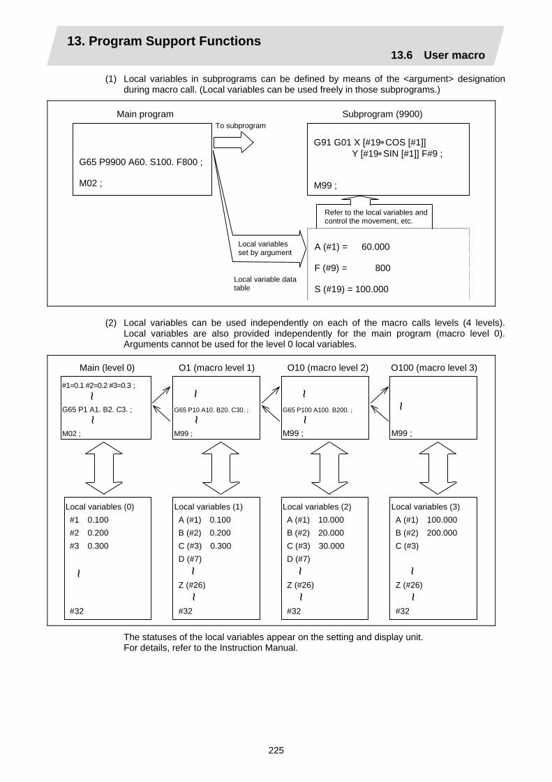
13. Program Support Functions 13.6 User macro
225
(1) Local variables in subprograms can be defined by means of the <argument> designation during macro call. (Local variables can be used freely in those subprograms.)
Main program Subprogram (9900)
G65 P9900 A60. S100. F800 ; M02 ;
G91 G01 X [#19∗COS [#1]] Y [#19∗SIN [#1]] F#9 ; M99 ;
To subprogram
A (#1) = 60.000 F (#9) = 800 S (#19) = 100.000
Refer to the local variables and control the movement, etc.
Local variables set by argument
Local variable data table
(2) Local variables can be used independently on each of the macro calls levels (4 levels). Local variables are also provided independently for the main program (macro level 0). Arguments cannot be used for the level 0 local variables.
Main (level 0)
#1=0.1 #2=0.2 #3=0.3 ; G65 P1 A1. B2. C3. ; M02 ;
~ ~
O1 (macro level 1)
G65 P10 A10. B20. C30. ;
M99 ;
O10 (macro level 2)
G65 P100 A100. B200. ;
M99 ;
O100 (macro level 3)
M99 ;
Local variables (0) #1 0.100 #2 0.200 #3 0.300 #32
Local variables (1) A (#1) 0.100 B (#2) 0.200 C (#3) 0.300 D (#7) Z (#26) #32
~ ~
~ ~
~
~ ~ ~
~ ~
Local variables (2) A (#1) 10.000 B (#2) 20.000 C (#3) 30.000 D (#7) Z (#26) #32
Local variables (3) A (#1) 100.000 B (#2) 200.000 C (#3) Z (#26) #32
~ ~
~ ~
~ ~
The statuses of the local variables appear on the setting and display unit. For details, refer to the Instruction Manual.

13. Program Support Functions 13.6 User macro
226
Macro interface inputs (#1000 ~ #1035, #1200 ~ #1295) : PLC → NC
The status of the interface input signals can be ascertained by reading out the values of variable numbers #1000 to #1035, #1200 to #1295. Available value which has been read out can be only one of 2 values: 1 or 0 (1: contact closed, 0: contact open). All the input signals from #1000 to #1031 can be read at once by reading out the value of variable number #1032. In the same manner, by reading the values for variable numbers #1033 to #1035, the input signals for #1200 to #1231, #1232 to #1263 and #1264 to #1295 can be read. Variable numbers #1000 to #1035, #1200 to #1295 are for readout only, and nothing can be placed in the left side member of their operation formula.
The word "input" means input to the NC side. To use the macro interface function by part system, set the bit selection parameter "#6454/bit0". Refer to (2) for the signals provided for each part system.
(1) Macro interface common to part systems (input)
System variable
No. of points Interface input signal System
variable No. of points
Interface input signal
#1000 1 Register R24 bit 0 #1016 1 Register R25 bit 0 #1001 1 Register R24 bit 1 #1017 1 Register R25 bit 1 #1002 1 Register R24 bit 2 #1018 1 Register R25 bit 2 #1003 1 Register R24 bit 3 #1019 1 Register R25 bit 3 #1004 1 Register R24 bit 4 #1020 1 Register R25 bit 4 #1005 1 Register R24 bit 5 #1021 1 Register R25 bit 5 #1006 1 Register R24 bit 6 #1022 1 Register R25 bit 6 #1007 1 Register R24 bit 7 #1023 1 Register R25 bit 7 #1008 1 Register R24 bit 8 #1024 1 Register R25 bit 8 #1009 1 Register R24 bit 9 #1025 1 Register R25 bit 9 #1010 1 Register R24 bit 10 #1026 1 Register R25 bit 10#1011 1 Register R24 bit 11 #1027 1 Register R25 bit 11#1012 1 Register R24 bit 12 #1028 1 Register R25 bit 12#1013 1 Register R24 bit 13 #1029 1 Register R25 bit 13#1014 1 Register R24 bit 14 #1030 1 Register R25 bit 14#1015 1 Register R24 bit 15 #1031 1 Register R25 bit 15
System variable
No. of points Interface input signal
#1032 32 Register R24, R25 #1033 32 Register R26, R27 #1034 32 Register R28, R29 #1035 32 Register R30, R31
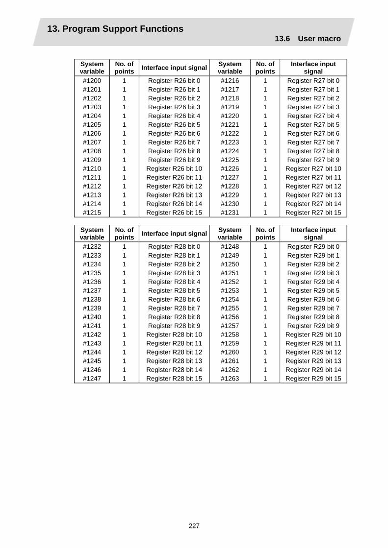
13. Program Support Functions 13.6 User macro
227
System variable
No. of points Interface input signal System
variable No. of points
Interface input signal
#1200 #1201 #1202 #1203 #1204 #1205 #1206 #1207 #1208 #1209 #1210 #1211 #1212 #1213 #1214 #1215
1 1 1 1 1 1 1 1 1 1 1 1 1 1 1 1
Register R26 bit 0 Register R26 bit 1 Register R26 bit 2 Register R26 bit 3 Register R26 bit 4 Register R26 bit 5 Register R26 bit 6 Register R26 bit 7 Register R26 bit 8 Register R26 bit 9 Register R26 bit 10 Register R26 bit 11 Register R26 bit 12 Register R26 bit 13 Register R26 bit 14 Register R26 bit 15
#1216 #1217 #1218 #1219 #1220 #1221 #1222 #1223 #1224 #1225 #1226 #1227 #1228 #1229 #1230 #1231
1 1 1 1 1 1 1 1 1 1 1 1 1 1 1 1
Register R27 bit 0 Register R27 bit 1 Register R27 bit 2 Register R27 bit 3 Register R27 bit 4 Register R27 bit 5 Register R27 bit 6 Register R27 bit 7 Register R27 bit 8 Register R27 bit 9 Register R27 bit 10Register R27 bit 11Register R27 bit 12Register R27 bit 13Register R27 bit 14Register R27 bit 15
System variable
No. of points Interface input signal System
variable No. of points
Interface input signal
#1232 #1233 #1234 #1235 #1236 #1237 #1238 #1239 #1240 #1241 #1242 #1243 #1244 #1245 #1246 #1247
1 1 1 1 1 1 1 1 1 1 1 1 1 1 1 1
Register R28 bit 0 Register R28 bit 1 Register R28 bit 2 Register R28 bit 3 Register R28 bit 4 Register R28 bit 5 Register R28 bit 6 Register R28 bit 7 Register R28 bit 8 Register R28 bit 9 Register R28 bit 10 Register R28 bit 11 Register R28 bit 12 Register R28 bit 13 Register R28 bit 14 Register R28 bit 15
#1248 #1249 #1250 #1251 #1252 #1253 #1254 #1255 #1256 #1257 #1258 #1259 #1260 #1261 #1262 #1263
1 1 1 1 1 1 1 1 1 1 1 1 1 1 1 1
Register R29 bit 0 Register R29 bit 1 Register R29 bit 2 Register R29 bit 3 Register R29 bit 4 Register R29 bit 5 Register R29 bit 6 Register R29 bit 7 Register R29 bit 8 Register R29 bit 9 Register R29 bit 10Register R29 bit 11Register R29 bit 12Register R29 bit 13Register R29 bit 14Register R29 bit 15

13. Program Support Functions 13.6 User macro
228
System variable
No. of points Interface input signal System
variable No. of points
Interface input signal
#1264 #1265 #1266 #1267 #1268 #1269 #1270 #1271 #1272 #1273 #1274 #1275 #1276 #1277 #1278 #1279
1 1 1 1 1 1 1 1 1 1 1 1 1 1 1 1
Register R30 bit 0 Register R30 bit 1 Register R30 bit 2 Register R30 bit 3 Register R30 bit 4 Register R30 bit 5 Register R30 bit 6 Register R30 bit 7 Register R30 bit 8 Register R30 bit 9 Register R30 bit 10 Register R30 bit 11 Register R30 bit 12 Register R30 bit 13 Register R30 bit 14 Register R30 bit 15
#1280 #1281 #1282 #1283 #1284 #1285 #1286 #1287 #1288 #1289 #1290 #1291 #1292 #1293 #1294 #1295
1 1 1 1 1 1 1 1 1 1 1 1 1 1 1 1
Register R31 bit 0 Register R31 bit 1 Register R31 bit 2 Register R31 bit 3 Register R31 bit 4 Register R31 bit 5 Register R31 bit 6 Register R31 bit 7 Register R31 bit 8 Register R31 bit 9 Register R31 bit 10Register R31 bit 11Register R31 bit 12Register R31 bit 13Register R31 bit 14Register R31 bit 15
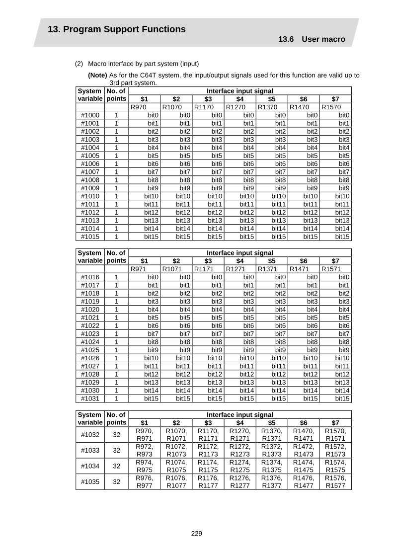
13. Program Support Functions 13.6 User macro
229
(2) Macro interface by part system (input)
(Note) As for the C64T system, the input/output signals used for this function are valid up to 3rd part system.
Interface input signal System variable
No. of points $1 $2 $3 $4 $5 $6 $7
R970 R1070 R1170 R1270 R1370 R1470 R1570 #1000 1 bit0 bit0 bit0 bit0 bit0 bit0 bit0#1001 1 bit1 bit1 bit1 bit1 bit1 bit1 bit1#1002 1 bit2 bit2 bit2 bit2 bit2 bit2 bit2#1003 1 bit3 bit3 bit3 bit3 bit3 bit3 bit3#1004 1 bit4 bit4 bit4 bit4 bit4 bit4 bit4#1005 1 bit5 bit5 bit5 bit5 bit5 bit5 bit5#1006 1 bit6 bit6 bit6 bit6 bit6 bit6 bit6#1007 1 bit7 bit7 bit7 bit7 bit7 bit7 bit7#1008 1 bit8 bit8 bit8 bit8 bit8 bit8 bit8#1009 1 bit9 bit9 bit9 bit9 bit9 bit9 bit9#1010 1 bit10 bit10 bit10 bit10 bit10 bit10 bit10#1011 1 bit11 bit11 bit11 bit11 bit11 bit11 bit11#1012 1 bit12 bit12 bit12 bit12 bit12 bit12 bit12#1013 1 bit13 bit13 bit13 bit13 bit13 bit13 bit13#1014 1 bit14 bit14 bit14 bit14 bit14 bit14 bit14#1015 1 bit15 bit15 bit15 bit15 bit15 bit15 bit15
Interface input signal System
variable No. of points $1 $2 $3 $4 $5 $6 $7
R971 R1071 R1171 R1271 R1371 R1471 R1571 #1016 1 bit0 bit0 bit0 bit0 bit0 bit0 bit0#1017 1 bit1 bit1 bit1 bit1 bit1 bit1 bit1#1018 1 bit2 bit2 bit2 bit2 bit2 bit2 bit2#1019 1 bit3 bit3 bit3 bit3 bit3 bit3 bit3#1020 1 bit4 bit4 bit4 bit4 bit4 bit4 bit4#1021 1 bit5 bit5 bit5 bit5 bit5 bit5 bit5#1022 1 bit6 bit6 bit6 bit6 bit6 bit6 bit6#1023 1 bit7 bit7 bit7 bit7 bit7 bit7 bit7#1024 1 bit8 bit8 bit8 bit8 bit8 bit8 bit8#1025 1 bit9 bit9 bit9 bit9 bit9 bit9 bit9#1026 1 bit10 bit10 bit10 bit10 bit10 bit10 bit10#1027 1 bit11 bit11 bit11 bit11 bit11 bit11 bit11#1028 1 bit12 bit12 bit12 bit12 bit12 bit12 bit12#1029 1 bit13 bit13 bit13 bit13 bit13 bit13 bit13#1030 1 bit14 bit14 bit14 bit14 bit14 bit14 bit14#1031 1 bit15 bit15 bit15 bit15 bit15 bit15 bit15
Interface input signal System
variable No. of points $1 $2 $3 $4 $5 $6 $7
#1032 32 R970, R971
R1070,R1071
R1170,R1171
R1270,R1271
R1370, R1371
R1470, R1471
R1570,R1571
#1033 32 R972, R973
R1072,R1073
R1172,R1173
R1272,R1273
R1372, R1373
R1472, R1473
R1572,R1573
#1034 32 R974, R975
R1074,R1075
R1174,R1175
R1274,R1275
R1374, R1375
R1474, R1475
R1574,R1575
#1035 32 R976, R977
R1076,R1077
R1176,R1177
R1276,R1277
R1376, R1377
R1476, R1477
R1576,R1577

13. Program Support Functions 13.6 User macro
230
Macro interface outputs (#1100 ~ #1135, #1300 ~ #1395) : NC → PLC
The interface output signals can be sent by substituting values in variable numbers #1100 to #1135, #1300 to #1395. An output signal can be only 0 or 1. All the output signals from #1100 to #1131 can be sent at once by substituting a value in variable number #1132. In the same manner, by reading the values for variable numbers #1133 to #1135, the output signals for #1300 to #1331, #1332 to #1363 and #1364 to #1395 can be read. (20 ~ 231) The status of the writing and output signals can be read in order to offset the #1100 to #1135, #1300 to #1395 output signals. Output here refers to the output from the NC.
The word "output" means output from the NC side. To use the macro interface function by part system, set the bit selection parameter "#6454/bit0". Refer to (2) for the signals provided for each part system.
(1) Macro interface common to part systems (output)
System variable
No. of points Interface input signal System
variable No. of points
Interface input signal
#1100 1 Register R124 bit 0 #1116 1 Register R125 bit 0#1101 1 Register R124 bit 1 #1117 1 Register R125 bit 1#1102 1 Register R124 bit 2 #1118 1 Register R125 bit 2#1103 1 Register R124 bit 3 #1119 1 Register R125 bit 3#1104 1 Register R124 bit 4 #1120 1 Register R125 bit 4#1105 1 Register R124 bit 5 #1121 1 Register R125 bit 5#1106 1 Register R124 bit 6 #1122 1 Register R125 bit 6#1107 1 Register R124 bit 7 #1123 1 Register R125 bit 7#1108 1 Register R124 bit 8 #1124 1 Register R125 bit 8#1109 1 Register R124 bit 9 #1125 1 Register R125 bit 9#1110 1 Register R124 bit 10 #1126 1 Register R125 bit 10#1111 1 Register R124 bit 11 #1127 1 Register R125 bit 11#1112 1 Register R124 bit 12 #1128 1 Register R125 bit 12#1113 1 Register R124 bit 13 #1129 1 Register R125 bit 13#1114 1 Register R124 bit 14 #1130 1 Register R125 bit 14#1115 1 Register R124 bit 15 #1131 1 Register R125 bit 15
System variable
No. of points Interface input signal
#1132 #1133 #1134 #1135
32 32 32 32
Register R124, R125Register R126, R127Register R128, R129Register R130, R131
(Note 1) The last values of the system variables #1100 to #1135, #1300 to #1395 sent are retained as 1 or 0.
(They are not cleared even with resetting.)
(Note 2) The following applies when any number except 1 or 0 is substituted into #1100 to #1131, #1300 to #1395.
<Blank> is treated as 0. Any number except 0 and <Blank> is treated as 1. Any value less than 0.00000001 is indefinite.

13. Program Support Functions 13.6 User macro
231
System variable
No. of points Interface input signal System
variable No. of points
Interface input signal
#1300 #1301 #1302 #1303 #1304 #1305 #1306 #1307 #1308 #1309 #1310 #1311 #1312 #1313 #1314 #1315
1 1 1 1 1 1 1 1 1 1 1 1 1 1 1 1
Register R126 bit 0 Register R126 bit 1 Register R126 bit 2 Register R126 bit 3 Register R126 bit 4 Register R126 bit 5 Register R126 bit 6 Register R126 bit 7 Register R126 bit 8 Register R126 bit 9 Register R126 bit 10Register R126 bit 11Register R126 bit 12Register R126 bit 13Register R126 bit 14Register R126 bit 15
#1316 #1317 #1318 #1319 #1320 #1321 #1322 #1323 #1324 #1325 #1326 #1327 #1328 #1329 #1330 #1331
1 1 1 1 1 1 1 1 1 1 1 1 1 1 1 1
Register R127 bit 0Register R127 bit 1Register R127 bit 2Register R127 bit 3Register R127 bit 4Register R127 bit 5Register R127 bit 6Register R127 bit 7Register R127 bit 8Register R127 bit 9Register R127 bit 10Register R127 bit 11Register R127 bit 12Register R127 bit 13Register R127 bit 14Register R127 bit 15
System variable
No. of points Interface input signal System
variable No. of points
Interface input signal
#1332 #1333 #1334 #1335 #1336 #1337 #1338 #1339 #1340 #1341 #1342 #1343 #1344 #1345 #1346 #1347
1 1 1 1 1 1 1 1 1 1 1 1 1 1 1 1
Register R128 bit 0 Register R128 bit 1 Register R128 bit 2 Register R128 bit 3 Register R128 bit 4 Register R128 bit 5 Register R128 bit 6 Register R128 bit 7 Register R128 bit 8 Register R128 bit 9 Register R128 bit 10Register R128 bit 11Register R128 bit 12Register R128 bit 13Register R128 bit 14Register R128 bit 15
#1348 #1349 #1350 #1351 #1352 #1353 #1354 #1355 #1356 #1357 #1358 #1359 #1360 #1361 #1362 #1363
1 1 1 1 1 1 1 1 1 1 1 1 1 1 1 1
Register R129 bit 0Register R129 bit 1Register R129 bit 2Register R129 bit 3Register R129 bit 4Register R129 bit 5Register R129 bit 6Register R129 bit 7Register R129 bit 8Register R129 bit 9Register R129 bit 10Register R129 bit 11Register R129 bit 12Register R129 bit 13Register R129 bit 14Register R129 bit 15

13. Program Support Functions 13.6 User macro
232
System variable
No. of points Interface input signal System
variable No. of points
Interface input signal
#1364 #1365 #1366 #1367 #1368 #1369 #1370 #1371 #1372 #1373 #1374 #1375 #1376 #1377 #1378 #1379
1 1 1 1 1 1 1 1 1 1 1 1 1 1 1 1
Register R130 bit 0 Register R130 bit 1 Register R130 bit 2 Register R130 bit 3 Register R130 bit 4 Register R130 bit 5 Register R130 bit 6 Register R130 bit 7 Register R130 bit 8 Register R130 bit 9 Register R130 bit 10Register R130 bit 11Register R130 bit 12Register R130 bit 13Register R130 bit 14Register R130 bit 15
#1380 #1381 #1382 #1383 #1384 #1385 #1386 #1387 #1388 #1389 #1390 #1391 #1392 #1393 #1394 #1395
1 1 1 1 1 1 1 1 1 1 1 1 1 1 1 1
Register R131 bit 0Register R131 bit 1Register R131 bit 2Register R131 bit 3Register R131 bit 4Register R131 bit 5Register R131 bit 6Register R131 bit 7Register R131 bit 8Register R131 bit 9Register R131 bit 10Register R131 bit 11Register R131 bit 12Register R131 bit 13Register R131 bit 14Register R131 bit 15
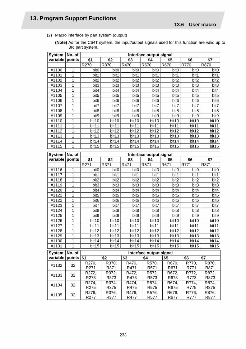
13. Program Support Functions 13.6 User macro
233
(2) Macro interface by part system (output)
(Note) As for the C64T system, the input/output signals used for this function are valid up to 3rd part system.
Interface output signal System variable
No. of points $1 $2 $3 $4 $5 $6 $7
R270 R370 R470 R570 R670 R770 R870 #1100 1 bit0 bit0 bit0 bit0 bit0 bit0 bit0#1101 1 bit1 bit1 bit1 bit1 bit1 bit1 bit1#1102 1 bit2 bit2 bit2 bit2 bit2 bit2 bit2#1103 1 bit3 bit3 bit3 bit3 bit3 bit3 bit3#1104 1 bit4 bit4 bit4 bit4 bit4 bit4 bit4#1105 1 bit5 bit5 bit5 bit5 bit5 bit5 bit5#1106 1 bit6 bit6 bit6 bit6 bit6 bit6 bit6#1107 1 bit7 bit7 bit7 bit7 bit7 bit7 bit7#1108 1 bit8 bit8 bit8 bit8 bit8 bit8 bit8#1109 1 bit9 bit9 bit9 bit9 bit9 bit9 bit9#1110 1 bit10 bit10 bit10 bit10 bit10 bit10 bit10#1111 1 bit11 bit11 bit11 bit11 bit11 bit11 bit11#1112 1 bit12 bit12 bit12 bit12 bit12 bit12 bit12#1113 1 bit13 bit13 bit13 bit13 bit13 bit13 bit13#1114 1 bit14 bit14 bit14 bit14 bit14 bit14 bit14#1115 1 bit15 bit15 bit15 bit15 bit15 bit15 bit15
Interface output signal System
variable No. of points $1 $2 $3 $4 $5 $6 $7
R271 R371 R471 R571 R671 R771 R871 #1116 1 bit0 bit0 bit0 bit0 bit0 bit0 bit0#1117 1 bit1 bit1 bit1 bit1 bit1 bit1 bit1#1118 1 bit2 bit2 bit2 bit2 bit2 bit2 bit2#1119 1 bit3 bit3 bit3 bit3 bit3 bit3 bit3#1120 1 bit4 bit4 bit4 bit4 bit4 bit4 bit4#1121 1 bit5 bit5 bit5 bit5 bit5 bit5 bit5#1122 1 bit6 bit6 bit6 bit6 bit6 bit6 bit6#1123 1 bit7 bit7 bit7 bit7 bit7 bit7 bit7#1124 1 bit8 bit8 bit8 bit8 bit8 bit8 bit8#1125 1 bit9 bit9 bit9 bit9 bit9 bit9 bit9#1126 1 bit10 bit10 bit10 bit10 bit10 bit10 bit10#1127 1 bit11 bit11 bit11 bit11 bit11 bit11 bit11#1128 1 bit12 bit12 bit12 bit12 bit12 bit12 bit12#1129 1 bit13 bit13 bit13 bit13 bit13 bit13 bit13#1130 1 bit14 bit14 bit14 bit14 bit14 bit14 bit14#1131 1 bit15 bit15 bit15 bit15 bit15 bit15 bit15
Interface output signal System
variable No. of points $1 $2 $3 $4 $5 $6 $7
#1132 32 R270, R271
R370, R371
R470, R471
R570, R571
R670, R671
R770, R771
R870, R871
#1133 32 R272, R273
R372, R373
R472, R473
R572, R573
R672, R673
R772, R773
R872, R873
#1134 32 R274, R275
R374, R375
R474, R475
R574, R575
R674, R675
R774, R775
R874, R875
#1135 32 R276, R277
R376, R377
R476, R477
R576, R577
R676, R677
R776, R777
R876, R877

13. Program Support Functions 13.6 User macro
234
Input signal Output signal
Read only Read/write
Mac
ro in
stru
ctio
ns
#1133 #1033
#1134
#1135
#1034
#1035
#1028
#1000
#1029
#1030
#1001
#1002
#1003
#1031
#1128
#1100
#1129
#1130
#1131
#1101
#1102
#1103
#1032 (R24,R25) #1132 (R124,R125)
32 bit 32 bit (R26,R27)
(R28,R29)
(R126,R127)
(R30,R31)
(R128,R129)
(R130,R131)
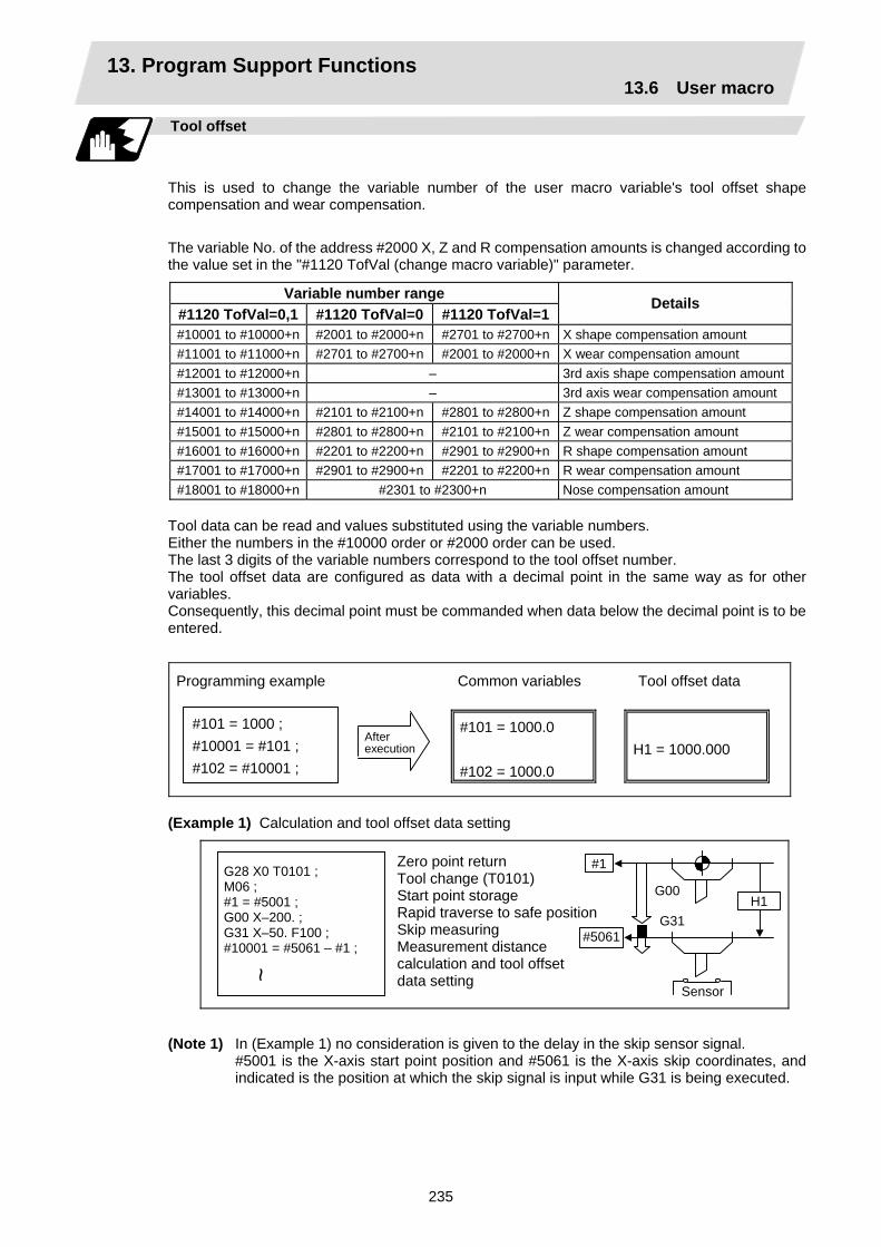
13. Program Support Functions 13.6 User macro
235
Tool offset
This is used to change the variable number of the user macro variable's tool offset shape compensation and wear compensation.
The variable No. of the address #2000 X, Z and R compensation amounts is changed according to the value set in the "#1120 TofVal (change macro variable)" parameter.
Variable number range #1120 TofVal=0,1 #1120 TofVal=0 #1120 TofVal=1
Details
#10001 to #10000+n #2001 to #2000+n #2701 to #2700+n X shape compensation amount #11001 to #11000+n #2701 to #2700+n #2001 to #2000+n X wear compensation amount #12001 to #12000+n – 3rd axis shape compensation amount#13001 to #13000+n – 3rd axis wear compensation amount #14001 to #14000+n #2101 to #2100+n #2801 to #2800+n Z shape compensation amount #15001 to #15000+n #2801 to #2800+n #2101 to #2100+n Z wear compensation amount #16001 to #16000+n #2201 to #2200+n #2901 to #2900+n R shape compensation amount #17001 to #17000+n #2901 to #2900+n #2201 to #2200+n R wear compensation amount #18001 to #18000+n #2301 to #2300+n Nose compensation amount
Tool data can be read and values substituted using the variable numbers. Either the numbers in the #10000 order or #2000 order can be used. The last 3 digits of the variable numbers correspond to the tool offset number. The tool offset data are configured as data with a decimal point in the same way as for other variables. Consequently, this decimal point must be commanded when data below the decimal point is to be entered.
Programming example Common variables Tool offset data
#101 = 1000 ; #10001 = #101 ; #102 = #10001 ;
After execution
#101 = 1000.0 #102 = 1000.0
H1 = 1000.000
(Example 1) Calculation and tool offset data setting
H1
Sensor
G00
G31
#1
#5061
(Note 1) In (Example 1) no consideration is given to the delay in the skip sensor signal. #5001 is the X-axis start point position and #5061 is the X-axis skip coordinates, and
indicated is the position at which the skip signal is input while G31 is being executed.
~
G28 X0 T0101 ; M06 ; #1 = #5001 ; G00 X–200. ; G31 X–50. F100 ; #10001 = #5061 – #1 ;
Zero point return Tool change (T0101) Start point storage Rapid traverse to safe positionSkip measuring Measurement distance calculation and tool offset data setting

13. Program Support Functions 13.6 User macro
236
Workpiece coordinate system offset
By using variable numbers #5201 to #532n, it is possible to read out the workpiece coordinate system offset data or to substitute values.
(Note) The number of axes which can be controlled differs according to the specifications. The last digit in the variable number corresponds to the control axis number.
Axis No.
Coordinate name
1st axis
2nd axis
3rd axis
4th axis • •
nth axis Remarks
External workpiece offset #5201 #5202 #5203 #5204 • • #520n
External workpiece offset specifications are required.
G54 #5221 #5222 #5223 #5224 • • #522n G55 #5241 #5242 #5243 #5244 • • #524n G56 #5261 #5262 #5263 #5264 • • #526n G57 #5281 #5282 #5283 #5284 • • #528n G58 #5301 #5302 #5303 #5304 • • #530n G59 #5321 #5322 #5323 #5324 • • #532n
Workpiece coordinate system offset specifications are required.
(Example 1)
-90. -20.
-20.
-10.
N1
N3
W1
W1 N11
Basic machine coordinate
External workpiece offset
W1 (G54)
W2 (G55)
G55G54
Basic machine coordinate system
W2 (G55)
W1 (G54)
G54 G55
This is an example where the eternal workpiece offset values are added to the workpiece coordinate (G54, G55) system offset values without changing the position of the workpiece coordinate systems.
N1 G28 X0 Z0 ; N2 #5221 = –20. #5223 = –20. ; N3 G00 G54 X0 Z0 ; N10 #5221 = –10. #5223 = –90. ; N11 G00 G54 X020 ; M02 ;
~ ~
G54 workpiece coordinate system defined by N2
G54 workpiece coordinate system defined by N10
N100 #5221 = #5221 + #5201 ; #5222 = #5222 + #5202 ; #5241 = #5241 + #5201 ; #5242 = #5242 + #5202 ; #5201 = 0 #5202 = 0 ;
~~
(Example 2)
Coordinate system after change
Coordinate system before change
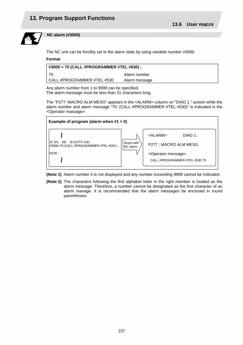
13. Program Support Functions 13.6 User macro
237
NC alarm (#3000)
The NC unit can be forcibly set to the alarm state by using variable number #3000.
Format
#3000 = 70 (CALL #PROGRAMMER #TEL #530) ;
70 Alarm number CALL #PROGRAMMER #TEL #530 Alarm message
Any alarm number from 1 to 9999 can be specified. The alarm message must be less than 31 characters long. The "P277: MACRO ALM MESG" appears in the <ALARM> column on "DIAG 1." screen while the alarm number and alarm message "70: (CALL #PROGRAMMER #TEL #530)" is indicated in the <Operator massage>.
Example of program (alarm when #1 = 0)
Stops with NC alarm
1F [#1 NE 0] GOTO 100 ; #3000=70 (CALL #PROGRAMMER #TEL #530 ) ; N100
<ALARM> DIAG 1. P277 : MACRO ALM MESG <Operator message> CALL #PROGRAMMER #TEL #530 70
~~
(Note 1) Alarm number 0 is not displayed and any number exceeding 9999 cannot be indicated.
(Note 2) The characters following the first alphabet letter in the right member is treated as the alarm message. Therefore, a number cannot be designated as the first character of an alarm manage. It is recommended that the alarm messages be enclosed in round parentheses.

13. Program Support Functions 13.6 User macro
238
Integrating time (#3001, #3002)
The integrating time can be read when the power is turned ON or automatic start or values can be substituted by using variable numbers #3001 and #3002.
Type Variable number Unit Contents when power
is switched on Initialization of contents Count conditions
Power ON 3001 At all times while power is ON
Automatic start 3002
1ms Same as when power is turned OFF
Value substituted for variable In-automatic start
The integrating time returns to zero in about 2.44 × 10¹¹ ms (approximately 7.7 years).
G65 P9010T (allowable time) ms ;
~ ~
To subprogram
#3001=0 ; WHILE [#3001LE#20] DO1 ; END1 ; M99 ;
O9010
Local variable Allowable time portion: DO1~END1 is repeated and when allowable time is reached, operations jumps to M99.
Entered in local variable #20 T#20 ———
Suppression of single block stop and miscellaneous function finish signal waiting
By substituting the values below in variable number #3003, it is possible to suppress single block stop in the subsequent blocks or to advance to the next block without waiting for the miscellaneous function (M, S, T, B) finish (FIN) signal.
#3003 Single block stop Miscellaneous function finish signal0 Not suppressed Wait 1 Suppressed Wait 2 Not suppressed No wait 3 Suppressed No wait
(Note 1) #3003 is cleared to zero by resetting.

13. Program Support Functions 13.6 User macro
239
Feed hold, feedrate override, G09 valid/invalid
By substituting the values below in variable number #3004, it is possible to make the feed hold, feedrate override and G09 functions either valid or invalid in the subsequent blocks.
Bit 0 Bit 1 Bit 2 #3004 contents (value) Feed hold Feedrate override G09 check
0 Valid Valid Valid 1 Invalid Valid Valid 2 Valid Invalid Valid 3 Invalid Invalid Valid 4 Valid Valid Invalid 5 Invalid Valid Invalid 6 Valid Invalid Invalid 7 Invalid Invalid Invalid
(Note 1) #3004 is cleared to zero by resetting.
(Note 2) The functions are valid when the above bits are 0 and invalid when they are 1.
Message display and stop
By using variable number #3006, the execution is stopped after the previous block has been executed and, if message display data have been commanded, then the corresponding message will be indicated on the operator message area.
Format
#3006=1 (TAKE FIVE) ;
TAKE FIVE Message
The message should not be longer than 31 characters and it should be enclosed within round parentheses.
Mirror image
By reading variable number #3007, it is possible to ascertain the status of mirror image at a particular point in time for each axis. The axes correspond to the bits of #3007. When the bits are 0, it means that the mirror image function is invalid; when they are 1, it means that it is valid.
Bit 15 14 13 12 11 10 9 8 7 6 5 4 3 2 1 0nth axis 4 3 2 1
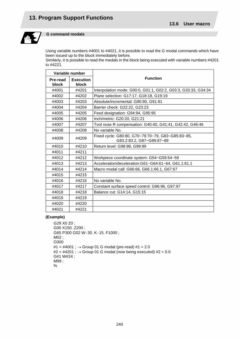
13. Program Support Functions 13.6 User macro
240
G command modals
Using variable numbers #4001 to #4021, it is possible to read the G modal commands which have been issued up to the block immediately before. Similarly, it is possible to read the medals in the block being executed with variable numbers #4201 to #4221.
Variable number Pre-read
block Execution
block Function
#4001 #4201 Interpolation mode: G00:0, G01:1, G02:2, G03:3, G33:33, G34:34#4002 #4202 Plane selection: G17:17, G18:18, G19:19 #4003 #4203 Absolute/incremental: G90:90, G91:91 #4004 #4204 Barrier check: G22:22, G23:23 #4005 #4205 Feed designation: G94:94, G95:95 #4006 #4206 Inch/metric: G20:20, G21:21 #4007 #4207 Tool nose R compensation: G40:40, G41:41, G42:42, G46:46 #4008 #4208 No variable No.
#4009 #4209 Fixed cycle: G80:80, G70~79:70~79, G83~G85:83~85, G83.2:83.2, G87~G89:87~89
#4010 #4210 Return level: G98:98, G99:99 #4011 #4211 #4012 #4212 Workpiece coordinate system: G54~G59:54~59 #4013 #4213 Acceleration/deceleration:G61~G64:61~64, G61.1:61.1 #4014 #4214 Macro modal call: G66:66, G66.1:66.1, G67:67 #4015 #4215 #4016 #4216 No variable No. #4017 #4217 Constant surface speed control: G96:96, G97:97 #4018 #4218 Balance cut: G14:14, G15:15 #4019 #4219 #4020 #4220 #4021 #4221
(Example) G29 X0 Z0 ; G00 X150. Z200 ; G65 P300 G02 W−30. K−15. F1000 ; M02 ; O300 #1 = #4001 ; → Group 01 G modal (pre-read) #1 = 2.0 #2 = #4201 ; → Group 01 G modal (now being executed) #2 = 0.0 G#1 W#24 ; M99 ; %
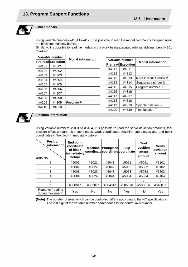
13. Program Support Functions 13.6 User macro
241
Other modals
Using variable numbers #4101 to #4120, it is possible to read the modal commands assigned up to the block immediately before. Similarly, it is possible to read the medals in the block being executed with variable numbers #4301 to #4320.
Variable number Pre-read Execution
Modal information
#4101 #4301 #4102 #4302 #4103 #4303 #4104 #4304 #4105 #4305 #4106 #4306 #4107 #4307 #4108 #4308 #4109 #4309 Feedrate F #4110 #4310
Position information
Using variable numbers #5001 to #5104, it is possible to read the servo deviation amounts, tool position offset amount, skip coordinates, work coordinates, machine coordinates and end point coordinates in the block immediately before.
Position information
Axis No.
End point coordinate
of block immediately
before
Machine coordinate
Workpiece coordinate
Skip coordinate
Tool position
offset amount
Servo deviation amount
1 #5001 #5021 #5041 #5061 #5081 #5101 2 #5002 #5022 #5042 #5062 #5082 #5102 3 #5003 #5023 #5043 #5063 #5083 #5203 4 #5004 #5024 #5044 #5064 #5084 #5104 : : : : : : : n #5000+n #5020+n #5040+n #5060+n #5080+n #5100+n
Remarks (reading during movement) Yes No No Yes No Yes
(Note) The number of axes which can be controlled differs according to the NC specifications. The last digit of the variable number corresponds to the control axis number.
Variable number Pre-read Execution
Modal information
#4111 #4311 #4112 #4312 #4113 #4313 Miscellaneous function M#4114 #4314 Sequence number N #4115 #4315 Program number O #4116 #4316 #4117 #4317 #4118 #4318 #4119 #4319 Spindle function S #4120 #4320 Tool function T
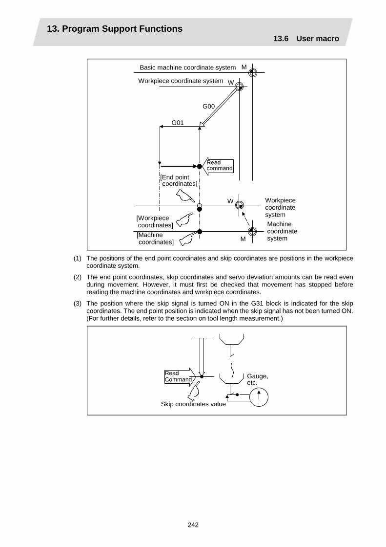
13. Program Support Functions 13.6 User macro
242
W
M
M
W
G01
Workpiece coordinate system Machine coordinate system
G00
Basic machine coordinate system
Workpiece coordinate system
Readcommand
[End pointcoordinates]
[Machinecoordinates]
[Workpiececoordinates]
(1) The positions of the end point coordinates and skip coordinates are positions in the workpiece coordinate system.
(2) The end point coordinates, skip coordinates and servo deviation amounts can be read even during movement. However, it must first be checked that movement has stopped before reading the machine coordinates and workpiece coordinates.
(3) The position where the skip signal is turned ON in the G31 block is indicated for the skip coordinates. The end point position is indicated when the skip signal has not been turned ON. (For further details, refer to the section on tool length measurement.)
Gauge, etc.
Read Command
Skip coordinates value
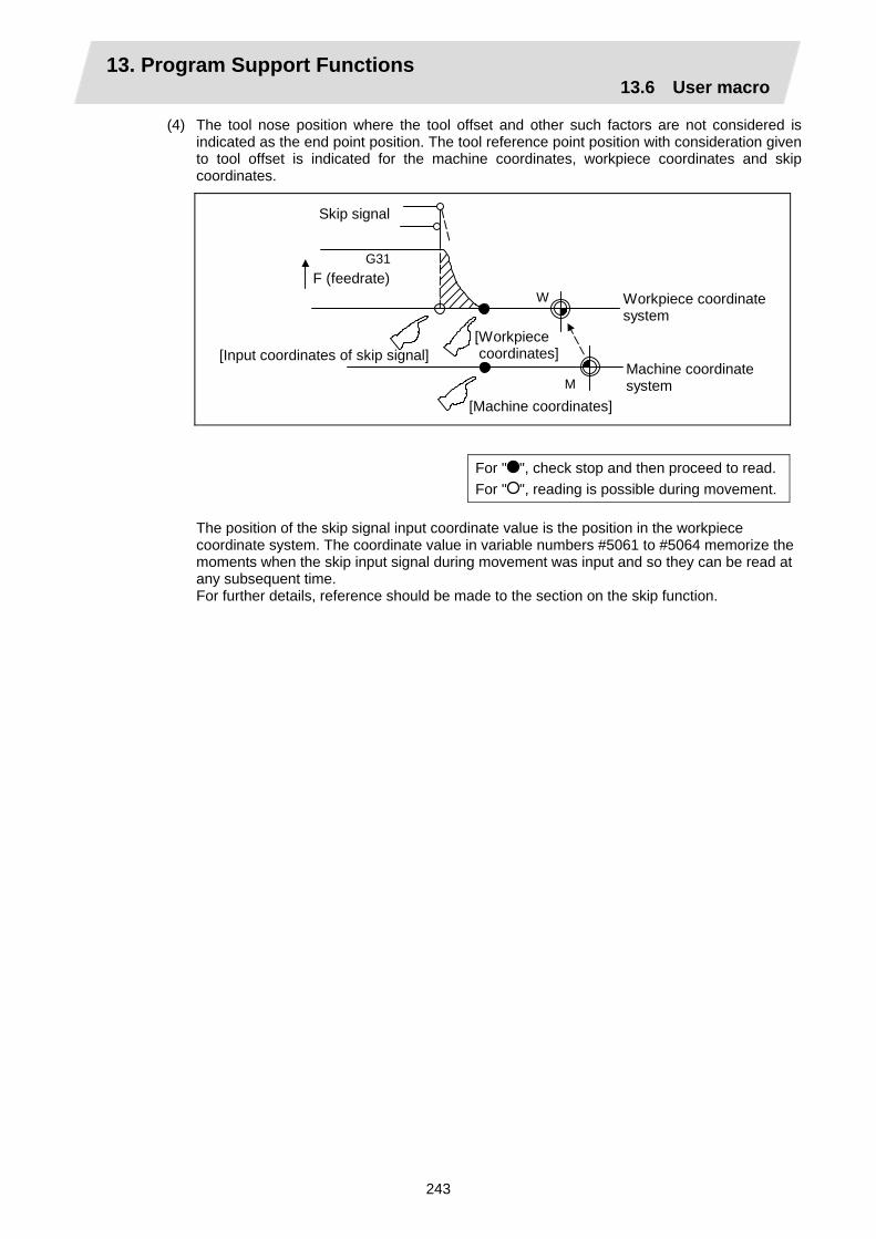
13. Program Support Functions 13.6 User macro
243
(4) The tool nose position where the tool offset and other such factors are not considered is indicated as the end point position. The tool reference point position with consideration given to tool offset is indicated for the machine coordinates, workpiece coordinates and skip coordinates.
G31
W
M
F (feedrate)
Skip signal
Machine coordinatesystem
[Workpiece coordinates]
[Machine coordinates]
[Input coordinates of skip signal]
Workpiece coordinate system
For " ", check stop and then proceed to read.For " ", reading is possible during movement.
The position of the skip signal input coordinate value is the position in the workpiece coordinate system. The coordinate value in variable numbers #5061 to #5064 memorize the moments when the skip input signal during movement was input and so they can be read at any subsequent time. For further details, reference should be made to the section on the skip function.
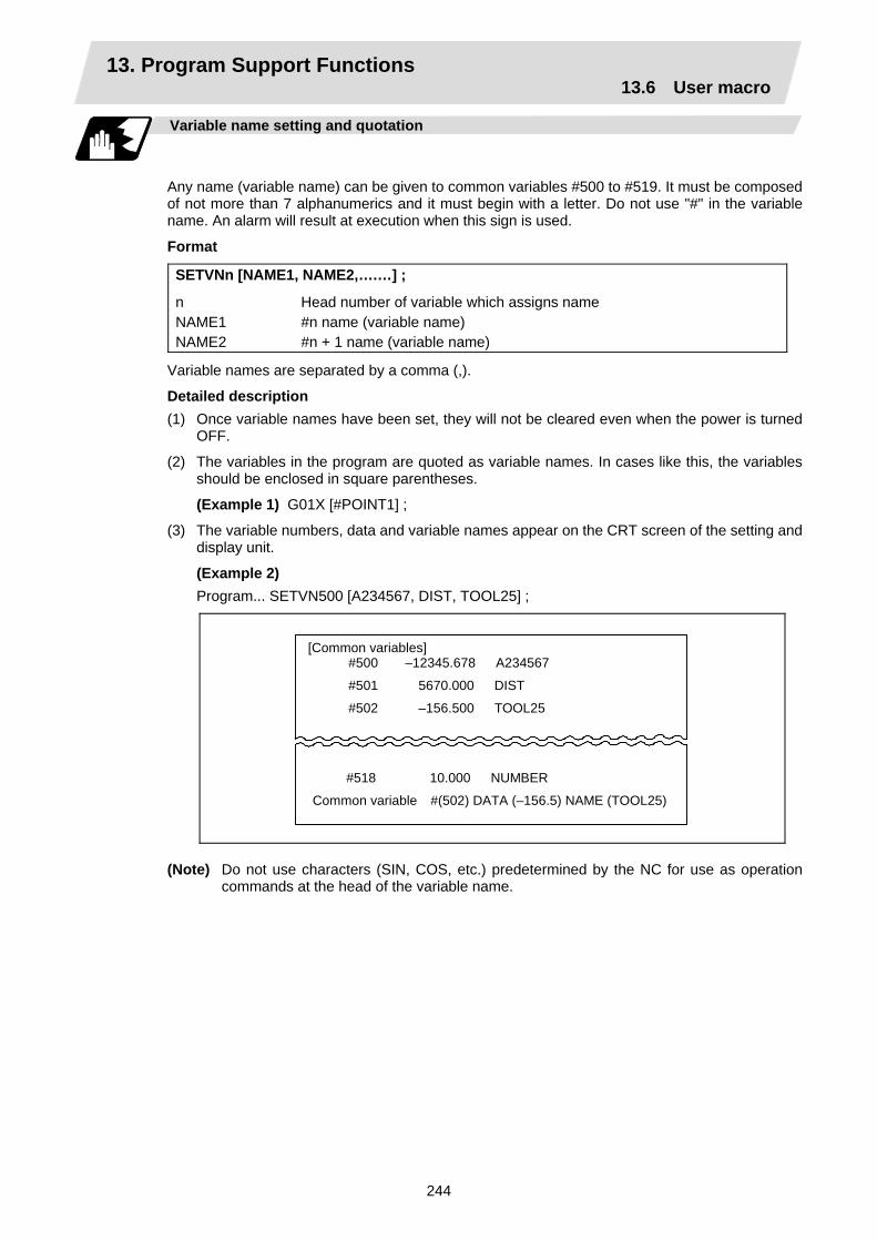
13. Program Support Functions 13.6 User macro
244
Variable name setting and quotation
Any name (variable name) can be given to common variables #500 to #519. It must be composed of not more than 7 alphanumerics and it must begin with a letter. Do not use "#" in the variable name. An alarm will result at execution when this sign is used.
Format
SETVNn [NAME1, NAME2,….…] ;
n Head number of variable which assigns name NAME1 #n name (variable name) NAME2 #n + 1 name (variable name)
Variable names are separated by a comma (,).
Detailed description (1) Once variable names have been set, they will not be cleared even when the power is turned
OFF.
(2) The variables in the program are quoted as variable names. In cases like this, the variables should be enclosed in square parentheses.
(Example 1) G01X [#POINT1] ;
(3) The variable numbers, data and variable names appear on the CRT screen of the setting and display unit.
(Example 2) Program... SETVN500 [A234567, DIST, TOOL25] ;
[Common variables] #500 –12345.678 A234567
#501 5670.000 DIST
#502 –156.500 TOOL25
#518 10.000 NUMBER
Common variable #(502) DATA (–156.5) NAME (TOOL25)
(Note) Do not use characters (SIN, COS, etc.) predetermined by the NC for use as operation
commands at the head of the variable name.
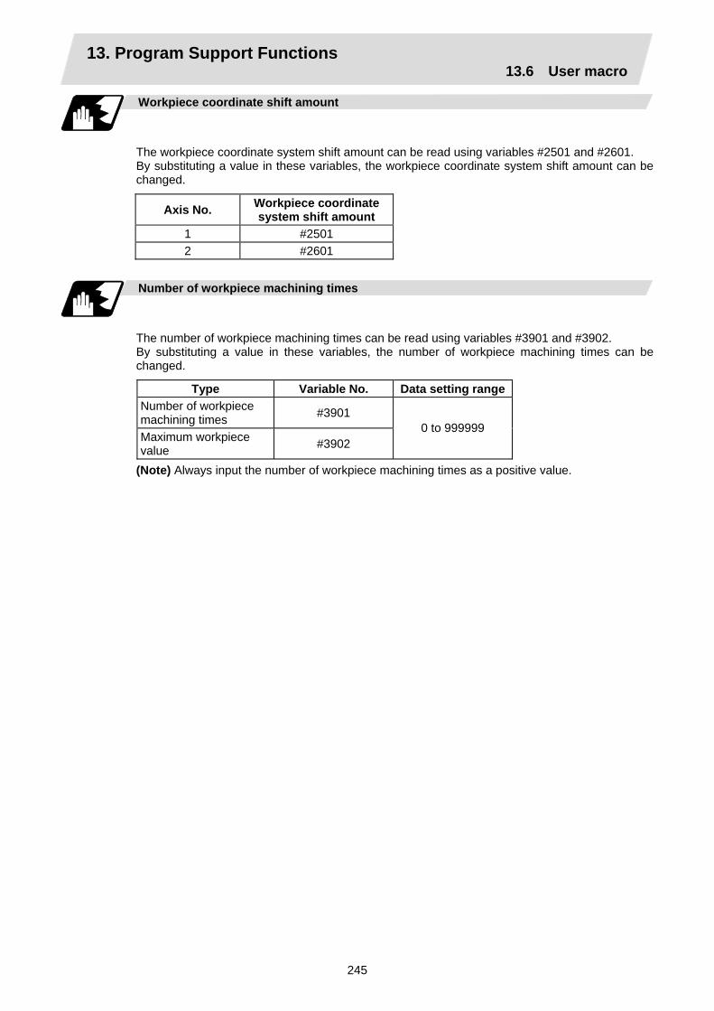
13. Program Support Functions 13.6 User macro
245
Workpiece coordinate shift amount
The workpiece coordinate system shift amount can be read using variables #2501 and #2601. By substituting a value in these variables, the workpiece coordinate system shift amount can be changed.
Axis No. Workpiece coordinate system shift amount
1 #2501 2 #2601
Number of workpiece machining times
The number of workpiece machining times can be read using variables #3901 and #3902. By substituting a value in these variables, the number of workpiece machining times can be changed.
Type Variable No. Data setting range Number of workpiece machining times #3901
Maximum workpiece value #3902
0 to 999999
(Note) Always input the number of workpiece machining times as a positive value.

13. Program Support Functions 13.6 User macro
246
Tool life management
(1) Definition of variable numbers
(a) Designation of group No. #60000
The tool life management data group No. to be read with #60001 to #64700 is designated by substituting a value in this variable. If a group No. is not designated, the data of the group registered first is read. This is valid until reset.
(b) Tool life management system variable No. (Read) #60001 to #64700
# ? ? ? ? ?
+ Variable No. or data typeData class6: Tool life management
(c) Details of data classification
Data class M System L System Remarks 00 For control For control Refer to following types05 Group No. Group No. Refer to registration No.10 Tool No. Tool No. Refer to registration No.15 Tool data flag Method Refer to registration No.20 Tool status Status Refer to registration No.25 Life data Life time/No. of times Refer to registration No.
30 Usage data Usage time/No. of times Refer to registration No.
35 Tool length compensation data – Refer to registration No.
40 Tool radius compensation data – Refer to registration No.
45 Auxiliary data – Refer to registration No.
The group No., L System method, and life data are common for the group.
(d) Registration No.
M System 1 to 200 L System 1 to 16
(e) Data type
Type M System L System Remarks1 Number of registered tools Number of registered tools 2 Life current value Life current value 3 Tool selected No. Tool selected No.
4 Number of remaining registered tools
Number of remaining registered tools
5 Signal being executed Signal being executed
6 Cutting time cumulative value (minute)
Cutting time cumulative value (minute)
7 Life end signal Life end signal 8 Life prediction signal Life prediction signal

13. Program Support Functions 13.6 User macro
247
Variable
No. Item Type Details Data range
60001 Number of registered tools
System common
Total number of tools registered in each group.
0 to 80
60002 Life current value
Usage time/No. of uses of tool being used.
Usage data of tool being used (If tool uses several compensation numbers, the total of the usage data for each compensation No.).
0 to 999999 min 0 to 999999 times
60003 Tool selected No.
Registration No. of tool being used.
Designated group's selection tool registration No. (If tool is not selected, the first tool of ST:1, or if ST:1 is not used, the first tool of ST:0. When all tools have reached their lives, the last tool).
0 to 16
60004 Remaining number of registered tools
Total number of "usable" tools in the group.
Number of tools registered in designated group for which ST is 0: Not used.
0 to 16
60005 Signal being executed
"1" when this group is used in program being executed.
"1" when tool in designated group is selected.
0/1
60006 Cutting time cumulative value (minute)
Indicates the time that this group is used in the program being executed.
60007 Life end signal
"1" when lives of all tools in this group have been reached.
"1" when all tools registered in designated group reach lives.
0/1
60008 Life prediction signal
For each group (Desig- nate group No. #60000)
"1" when new tool is selected with next command in this group.
"1" when there is a tool for which ST is 0: Not used in the tools registered the designated group, and there are no tools for which ST is 1: Tools in use.
0/1

13. Program Support Functions 13.6 User macro
248
Variable
No. Item Type Details Data range
60500 +***
Group No. This group's No. 1 to 9999
61000 +***
Tool No. Tool's No. and compensation No.
Tool No. + compensation No. (When tool No. = 22 and compensation No. = 01, 2201=899H)
0 to 9999
61500 +***
Method Whether to management this group's life as time or No. of uses.
0: Time, 1: No. of uses
0/1
62000 +***
Status Tool usage state
0: Not used tool 1: Tool being used 2: Normal life tool 3: Tool skip tool
0 to 3
62500 +***
Life time/No. of uses
This group's tool life value 0 to 999999 min 0 to 999999 times
63000 +***
Usage time/No. of uses
Each group/ registra-tion No.(Group No. #60000/ registra-tion No. *** is desig- nated.) Note the group No., method and life are common for the groups. 0 to 999999
min 0 to 999999 times
63500 +***
–
64000 +***
–
64500 +***
–

13. Program Support Functions 13.6 User macro
249
Example of program
(1) Normal commands
#101 = #60001 ; ...... Reads the number of registered tools. #102 = #60002 ; ...... Reads the life current value. #103 = #60003 ; ...... Reads the tool selection No. #60000 = 10 ; .......... Designates the group No. of the life data to be
read. #104 = #60004 ; ...... Reads the remaining number of registered
tools in group 10. #105 = #60005 ; ...... Reads the signal being executed in group 10. #111 = #61001 ; ...... Reads the group 10, #1 tool No. #112 = #62001 ; ...... Reads the group 10, #1 status. #113 = #61002 ; ...... Reads the group 10, #2 tool No. %
(2) When group No. is not designated #104 = #60004 ; ...... Reads the remaining number of registered tools in the group registered
first. #111 = #61001 ; ...... Reads the #1 tool No. in the group registered first. %
(3) When non-registered group No. is designated (Group 9999 does not exist.) #60000 = 9999 ; ...... Designates the group No. #104 = #60004 ; ...... #104 = –1.
(4) When registration No. not used is designated (Group 10 has 15 tools) #60000 = 10 ; .......... Designates the group No. #111 = #61016 ; ...... #101 = –1.
(5) When registration No. out of the specifications is designated #6000 = 10 ; #111 = #61017 ; ...... Program error (P241)
(6) When tool life management data is registered with G10 command after group No. is
designated #60000 = 10 ; .......... Designates the group No. G10 L3 ; ................... Starts the life management data registration. P10 LLn NNn ; ........ 10 is the group No., Ln is the life per tool,
Nn is the method. TTn ; ........................ Tn is the tool No. : G11 ; ....................... Registers the group 10 data with the G10 ................................. command. #111 = #61001 ; ...... Reads the group 10, #1 tool No. G10 L3 ; ................... Starts the life management data registration. P1 LLn NNn ; .......... 1 is the group No., Ln is the life per tool, ................................. Nn is the method. TTn ; ........................ Tn is the tool No. : G11 ; ........................ Registers the life data with the G10 command. ................................. (The registered data is deleted.) #111 = 61001 ; ........ Group 10 does not exist. #111 = –1.
Designated program No. is valid until reset.
The group 10 life data is registered.
The life data other than group 10 is registered.

13. Program Support Functions 13.6 User macro
250
Precautions
(1) If the tool life management system variable is commanded without designating a group No.,
the data of the group registered at the head of the registered data will be read.
(2) If a non-registered group No. is designated and the tool life management system variable is commanded, "–1" will be read as the data.
(3) If an unused registration No. tool life management system variable is commanded, "–1" will be read as the data.
(4) Once commanded, the group No. is valid until NC reset.
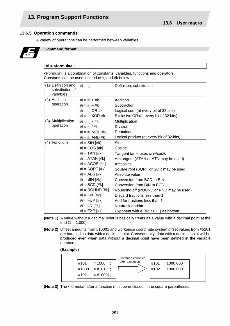
13. Program Support Functions 13.6 User macro
251
13.6.5 Operation commands A variety of operations can be performed between variables.
Command format
#i = <formula> ;
<Formula> is a combination of constants, variables, functions and operators. Constants can be used instead of #j and #k below.
(1) Definition and substitution of variables
#i = #j Definition, substitution
(2) Addition operation
#i = #j + #k #i = #j – #k #i = #j OR #k #i = #j XOR #k
Addition Subtraction Logical sum (at every bit of 32 bits) Exclusive OR (at every bit of 32 bits)
(3) Multiplication operation
#i = #j ∗ #k #i = #j / #k #i = #j MOD #k #i = #j AND #k
Multiplication Division Remainder Logical product (at every bit of 32 bits)
(4) Functions
#i = SIN [#k] #i = COS [#k] #i = TAN [#k] #i = ATAN [#k] #i = ACOS [#k] #i = SQRT [#k] #i = ABS [#k] #i = BIN [#k] #i = BCD [#k] #i = ROUND [#k] #i = FIX [#k] #i = FUP [#k] #i = LN [#k] #i = EXP [#k]
Sine Cosine Tangent tan θ uses sinθ/cosθ. Arctangent (ATAN or ATN may be used) Arccosine Square root (SQRT or SQR may be used) Absolute value Conversion from BCD to BIN Conversion from BIN to BCD Rounding off (ROUND or RND may be used) Discard fractions less than 1 Add for fractions less than 1 Natural logarithm Exponent with e (=2.718...) as bottom
(Note 1) A value without a decimal point is basically treats as a value with a decimal point at the end (1 = 1.000).
(Note 2) Offset amounts from #10001 and workpiece coordinate system offset values from #5201 are handled as data with a decimal point. Consequently, data with a decimal point will be produced even when data without a decimal point have been defined in the variable numbers.
(Example)
(Note 3) The <formula> after a function must be enclosed in the square parentheses.
#101 = 1000 ; #10001 = #101 ; #102 = #10001 ;
#101 1000.000 #102 1000.000
Common variables after execution

13. Program Support Functions 13.6 User macro
252
Sequence of operations
(1) The sequence of the operations (1) to (3) is, respectively, the functions followed by the
multiplication operation followed in turn by the addition operation.
#101 = #111 + #112 ∗ SIN [#113] (1) Function (2) Multiplication operation (3) Addition operation
(2) The part to be given priority in the operation sequence should be enclosed in brackets. Up to 5
pairs of such brackets including those for the functions may be used.
#101=SQRT [ [ [#111 – #112] ∗ SIN [#113] + [#114] ∗ #115] ;
First pair of brackets
Second pair of brackets
Third pair of brackets

13. Program Support Functions 13.6 User macro
253
Examples of operation commands
(1) Main program and argument designation
G65 P100 A10 B20. ;#101=100.000 #102=200.000 ;
#1 #2 #101 #102
10.00020.000
100.000200.000
(2) Definition and substitution (=)
#1=1000 #2=1000. #3=#101 #4=#102 #5=#5041
#1 #2 #3 #4 #5
1000.0001000.000
100.000200.000−10.000
(3) Addition and subtraction (+, −)
#11=#1+1000 #12=#2−50. #13=#101+#1 #14=#5041−3. #15=#5041+#102
#11 #12 #13 #14 #15
2000.000950.000
1100.000−13.000190.000
#3 = 01100100 14 = 00001110
(4) Logical sum (OR)
#3=100 #4=#3 OR 14
#4 = 01101110 = 110 #3 = 01100100 14 = 00001110
(5) Exclusive OR (XOR)
#3=100 #4=#3 XOR 14
#4 = 01101010 = 106 (6) Multiplication
and division (∗, /)
#21=100∗100 #22=100.∗100 #23=100∗100 #24=100.∗100. #25=100/100 #26=100./100 #27=100/100. #28=100./100. #29=5041∗#101 #30=5041/#102
#21#22#23#24#25#26#27#28#29#30
10000.00010000.00010000.00010000.000
1.0001.0001.0001.000
−1000.000–0.050
(7) Remainder (MOD)
#31=#19 MOD #20 #19/#20 = 48/9 = 5 with 3 over
(8) Logical product (AND)
#9=100 #10=#9 AND 15
#9 = 01100100 15 = 00001111
#10 = 00000100 = 4
From common variables
From offset amount

13. Program Support Functions 13.6 User macro
254
(9) Sin (SIN) #501 = SIN [60]
#502 = SIN [60.] #503 = 1000∗SIN [60] #504 = 1000∗SIN [60.] #505 = 1000.∗SIN [60] #506 = 1000.∗SIN [60.] (Note) SIN [60] is equivalent to SIN [60.]
#501 #502 #503 #504 #505 #506
0.860 0.860
866.025 866.025 866.025 866.025
(10) Cosine (COS)
#541 = COS [45] #542 = COS [45.] #543 = 1000∗COS [45] #544 = 1000∗COS [45.] #545 = 1000.∗COS [45] #546 = 1000.∗COS [45.] (Note) COS [45] is equivalent to COS [45.]
#541 #542 #543 #544 #545 #546
0.707 0.707
707.107 707.107 707.107 707.107
(11) Tangent (TAN)
#551 = TAN [60] #552 = TAN [60.] #553 = 1000∗TAN [60] #554 = 1000∗TAN [60.] #555 = 1000.∗TAN [60] #556 = 1000.∗TAN [60.] (Note) TAN [60] is equivalent to TAN [60.]
#551 #552 #553 #554 #555 #556
1.732 1.732
1732.051 1732.051 1732.051 1732.051
(12) Arctangent (ATAN or ATN)
#561 = ATAN [173205/100000] #562 = ATAN [173205/100.] #563 = ATAN [173.205/100000] #564 = ATAN [173.205/100.] #565 = ATAN [1.732]
#561 #562 #563 #564 #565
60.000 60.000 60.000 60.000 59.999
(13) Arccosine (ACOS)
#521 = ACOS [100./141.421] #522 = ACOS [100./141.421] #523 = ACOS [1000./1414.213] #524 = ACOS [10./14.142] #525 = ACOS [0.707]
#521 #522 #523 #524 #525
45.000 45.000 45.000 44.999 45.009
(14) Square root (SQR or SQRT)
#571 = SQRT [1000] #572 = SQRT [1000.] #573 = SQRT [10. ∗10. +20. ∗20.] #574 = SQRT [#14∗#14 + #15∗#15] (Note) In order to increase the accuracy,
proceed with the operation inside parentheses.
#571 #572 #573 #574
31.623 31.623 22.361
190.444
(15) Absolute value (ABS)
#576 = −1000 #577 = ABS [#576] #3 = 70. #4 = −50. #580 = ABS [#4 − #3]
#576 #577 #580
−1000.000 1000.000
120.000
(16) BIN, BCD #1 = 100 #11 = BIN [#1] #12 = BCD [#1]
#11 #12
64
256

13. Program Support Functions 13.6 User macro
255
(17) Rounding off
(ROUND or RND)
#21 = ROUND [14/3] #22 = ROUND [14./3] #23 = ROUND [14/3.] #24 = ROUND [14./3.] #25 = ROUND [−14/3] #26 = ROUND [−14./3] #27 = ROUND [−14/3.] #28 = ROUND [−14./3.]
#21 #22 #23 #24 #25 #26 #27 #28
5 5 5 5
−5 −5 −5 −5
(18) Discarding fractions below decimal point (FIX)
#21 = FIX [14/3] #22 = FIX [14./3] #23 = FIX [14/3.] #24 = FIX [14./3.] #25 = FIX [−14/3] #26 = FIX [−14./3] #27 = FIX [−14/3.] #28 = FIX [−14./3.]
#21 #22 #23 #24 #25 #26 #27 #28
4.000 4.000 4.000 4.000 −4.000 −4.000 −4.000 −4.000
(19) Adding fractions less than 1 (FUP)
#21 = FUP [14/3] #22 = FUP [14./3] #23 = FUP [14/3.] #24 = FUP [14./3.] #25 = FUP [−14/3] #26 = FUP [−14./3] #27 = FUP [−14/3.] #28 = FUP [−14./3.]
#21 #22 #23 #24 #25 #26 #27 #28
5.000 5.000 5.000 5.000 −5.000 −5.000 −5.000 −5.000
(20) Natural logarithms (LN)
#101 = LN [5] #102 = LN [0.5] #103 = LN [−5]
#101 #102 Error
1.609 −0.693 "P282"
(21) Exponents (EXP)
#104 = EXP [2] #105 = EXP [1] #106 = EXP [−2]
#104 #105 #106
7.389 2.718 0.135
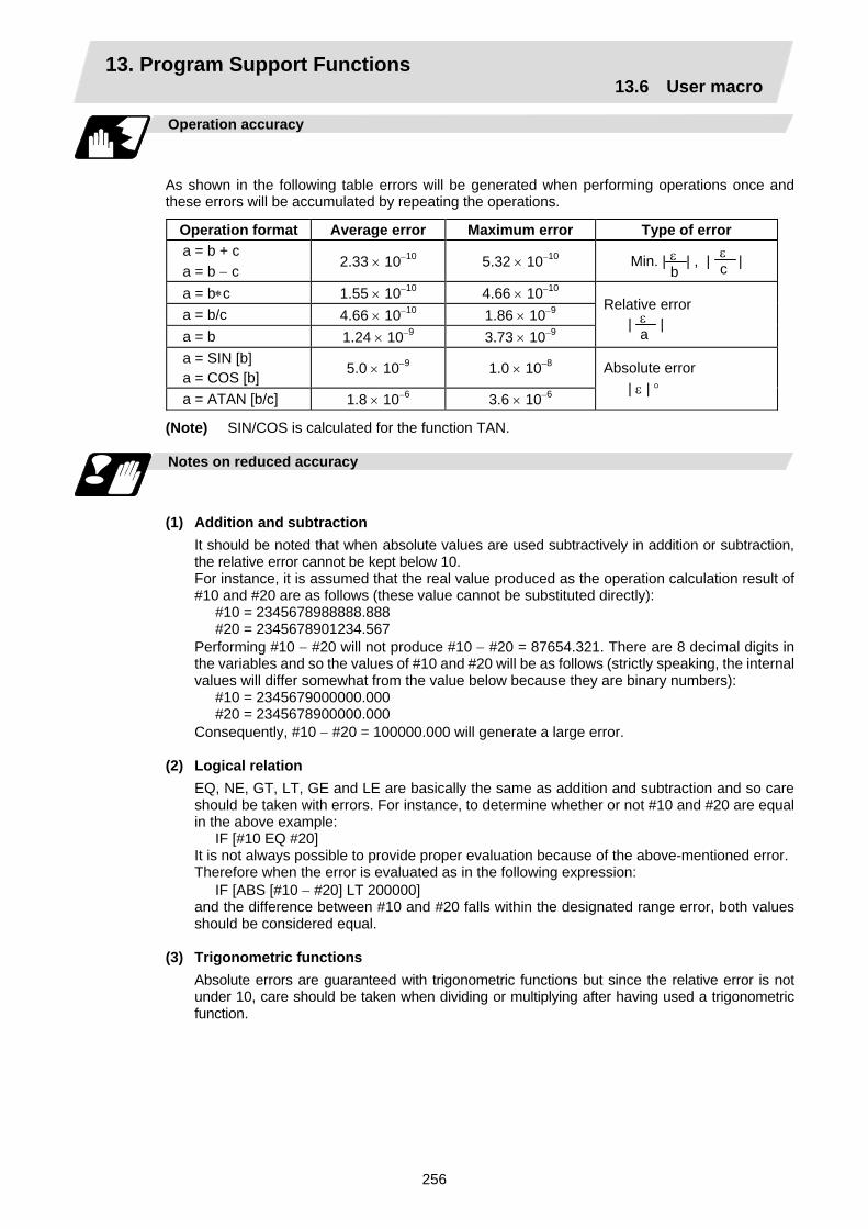
13. Program Support Functions 13.6 User macro
256
Operation accuracy
As shown in the following table errors will be generated when performing operations once and these errors will be accumulated by repeating the operations.
Operation format Average error Maximum error Type of error a = b + c a = b − c
2.33 × 10⁻¹⁰ 5.32 × 10⁻¹⁰ Min. | | , | |
a = b∗c 1.55 × 10⁻¹⁰ 4.66 × 10⁻¹⁰ a = b/c 4.66 × 10⁻¹⁰ 1.86 × 10⁻⁹ a = b 1.24 × 10⁻⁹ 3.73 × 10⁻⁹
Relative error | |
a = SIN [b] a = COS [b] 5.0 × 10⁻⁹ 1.0 × 10⁻⁸
a = ATAN [b/c] 1.8 × 10⁻⁶ 3.6 × 10⁻⁶
Absolute error | ε | °
(Note) SIN/COS is calculated for the function TAN.
Notes on reduced accuracy
(1) Addition and subtraction
It should be noted that when absolute values are used subtractively in addition or subtraction, the relative error cannot be kept below 10. For instance, it is assumed that the real value produced as the operation calculation result of #10 and #20 are as follows (these value cannot be substituted directly):
#10 = 2345678988888.888 #20 = 2345678901234.567
Performing #10 − #20 will not produce #10 − #20 = 87654.321. There are 8 decimal digits in the variables and so the values of #10 and #20 will be as follows (strictly speaking, the internal values will differ somewhat from the value below because they are binary numbers):
#10 = 2345679000000.000 #20 = 2345678900000.000
Consequently, #10 − #20 = 100000.000 will generate a large error.
(2) Logical relation EQ, NE, GT, LT, GE and LE are basically the same as addition and subtraction and so care should be taken with errors. For instance, to determine whether or not #10 and #20 are equal in the above example:
IF [#10 EQ #20] It is not always possible to provide proper evaluation because of the above-mentioned error. Therefore when the error is evaluated as in the following expression:
IF [ABS [#10 − #20] LT 200000] and the difference between #10 and #20 falls within the designated range error, both values should be considered equal.
(3) Trigonometric functions
Absolute errors are guaranteed with trigonometric functions but since the relative error is not under 10, care should be taken when dividing or multiplying after having used a trigonometric function.
ε b
ε c
ε a

13. Program Support Functions 13.6 User macro
257
13.6.6 Control commands
The flow of programs can be controlled by IF ~ GOTO ~ and WHILE ~ DO ~.
Branching
Format
IF [conditional expression] GOTO n ; (where n = sequence number in the program)
When the condition is satisfied, control branches to "n" and when it is not satisfied, the next block is executed. IF [conditional expression] can be omitted and, when it is, control passes to "n" unconditionally. The following types of [conditional expressions] are available.
#i EQ #j = When #i and #j are equal #i NE #j ≠ When #i and #j are not equal #i GT #j > When #i is greater than #j #i LT #j < When #i is less than #j #i GE #j ≥ When #i is #j or more #i LE #j ≤ When #i is #j or less
"n" of "GOTO n" must always be in the same program. Program error (P231) will result if it is not. A formula or variable can be used instead of #i, #j and "n". In the block with sequence number "n" which will be executed after a "GOTO n" command, the sequence number Nn must always be at the head of the block. Otherwise, program error (P231) will result. If "/" is at the head of the block and Nn follows, control can be branched to the sequence number.
N10 #22=#20 #23=#21 ; IF [#2 EQ1] GOTO100 ; #22=#20–#3 ; #23=#21–#4 ; N100 X#22 Z#23 ; #1=#1+#1 ;
~ ~
~
Branching to N100 when content of #2 is 1
Bra
nch
sear
ch
N100
Branch search
With N10
To head
(Note 1) When the sequence number of the branch destination is searched, the search is conducted up to the end of the program (% code) from the block following "IF….. ;" and if it is not found, it is conducted up to the block before "IF ..... ;". Therefore, branch searches in the opposite direction to the program flow will take longer to execute compared with branch searches in the forward direction.
(Note 2) Only compare EQ and NE by integers. Use GE, GT, LE and LT for comparison when there are numbers below the decimal point.

13. Program Support Functions 13.6 User macro
258
Repetition
Format
WHILE [conditional expression] DOm ; (m =1, 2, 3 ..... 127) END m ;
While the conditional expression is established, the blocks from the following block to ENDm are repeatedly executed; when it is not established, execution moves to the block after ENDm. DOm may come before WHILE. "WHILE [conditional expression] DOm" and "ENDm" must be used as a pair. If "WHILE [conditional expression]" is omitted, these blocks will be repeatedly ad infinitum. The repeating identification numbers range from 1 to 127 (DO1, DO2, DO3, ..... DO127). Up to 27 nesting levels can be used.
(1) Same identification number can be used any number of times.
(2) Any number may be used for the WHILE~ DOm identification number.
(3) Up to 27 nesting levels for WHILE~DOm. "m" is any number form 1 to 127 for the nesting depth. (Note) With nesting, "m" which has been
used once cannot be used.
(4) The number of WHILE~DOm nesting levels cannot exceed 27.
~
WHILE ~ DO1 ; END1 ;
WHILE ~ DO1 ; END1 ;
Possible
Possible
WHILE ~ DO1 ; END1 ;
~
WHILE ~ DO3 ; END3 ;
~ ~
WHILE ~ DO2 ; END2 ;
~ ~
WHILE ~ DO1 ; END1 ;
~ ~
Possible
WHILE ~ DO1 ;
WHILE ~ DO2 ;
WHILE ~ DO3 ;
WHILE ~ DO28 ;
END3 ;
END28 ;
~ ~
~ ~
END2 ;:
END1 ;
~
:
Not possible
Possible
DO2
DO1
DO27
END1 ;
WHILE ~ DO1 ;
WHILE ~ DO2 ;
WHILE~DO27 ;
END2 ;
END27 ;
: :
: :
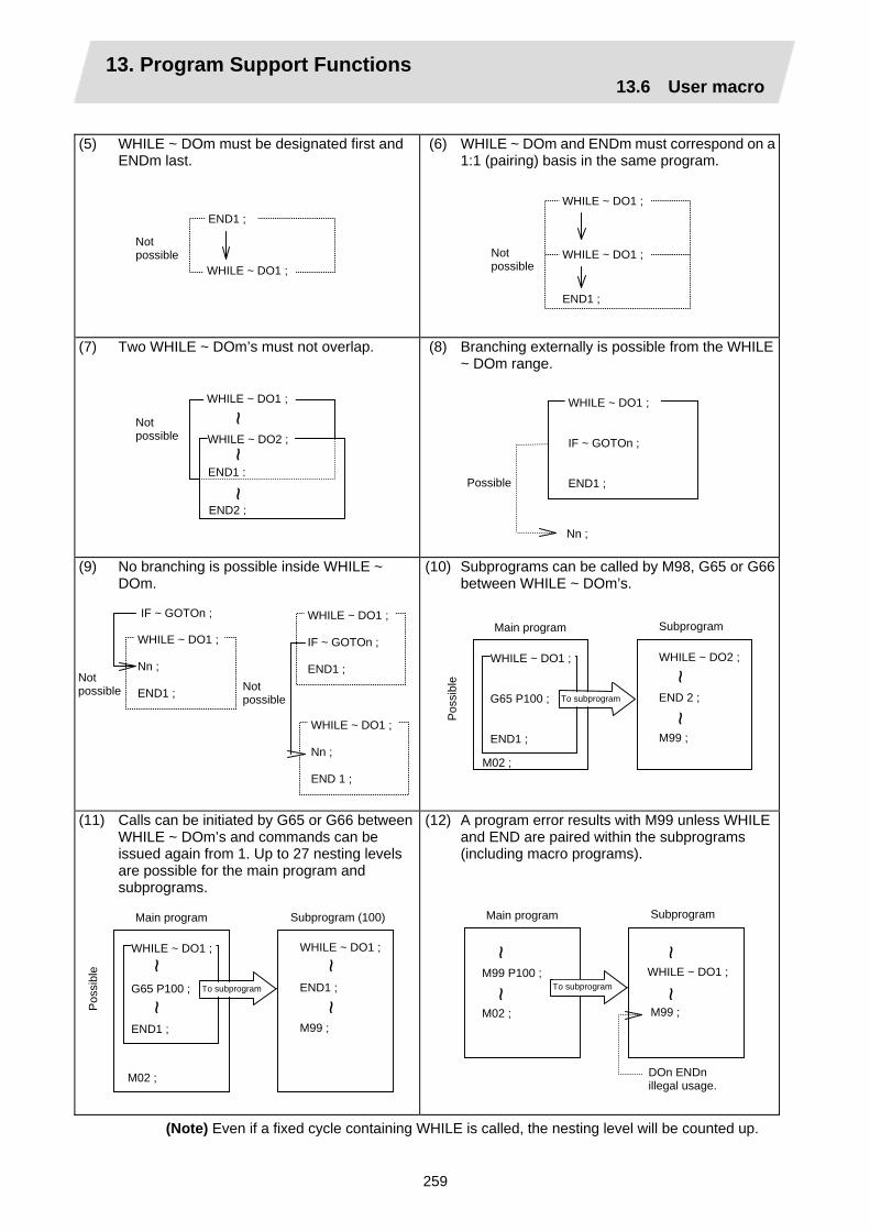
13. Program Support Functions 13.6 User macro
259
(5) WHILE ~ DOm must be designated first and
ENDm last.
(6) WHILE ~ DOm and ENDm must correspond on a 1:1 (pairing) basis in the same program.
(7) Two WHILE ~ DOm’s must not overlap.
(8) Branching externally is possible from the WHILE ~ DOm range.
(9) No branching is possible inside WHILE ~ DOm.
(10) Subprograms can be called by M98, G65 or G66 between WHILE ~ DOm’s.
(11) Calls can be initiated by G65 or G66 between WHILE ~ DOm’s and commands can be issued again from 1. Up to 27 nesting levels are possible for the main program and subprograms.
(12) A program error results with M99 unless WHILE and END are paired within the subprograms (including macro programs).
(Note) Even if a fixed cycle containing WHILE is called, the nesting level will be counted up.
END1 ;
WHILE ~ DO1 ;
Not possible Not
possible WHILE ~ DO1 ;
END1 ;
WHILE ~ DO1 ;
Nn ;
WHILE ~ DO1 ; IF ~ GOTOn ; END1 ; Possible
Not possible Not
possible
WHILE ~ DO1 ; Nn ; END1 ;
IF ~ GOTOn ;
WHILE ~ DO1 ; Nn ; END 1 ;
WHILE ~ DO1 ; IF ~ GOTOn ; END1 ;
END2 ;
END1 ;
WHILE ~ DO2 ;
WHILE ~ DO1 ;
Not possible
~ ~
~
WHILE ~ DO1 ; END1 ; M99 ;
WHILE ~ DO1 ; G65 P100 ; END1 ;
Subprogram (100) Main program
Pos
sibl
e
To subprogram
M02 ;
~ ~
~ ~
WHILE ~ DO1 ; M99 ;
M99 P100 ; M02 ;
Subprogram Main program
To subprogram
DOn ENDn illegal usage.
~ ~
~ ~
WHILE ~ DO2 ; END 2 ; M99 ;
WHILE ~ DO1 ; G65 P100 ; END1 ;
SubprogramMain program
Pos
sibl
e
To subprogram ~
~
M02 ;
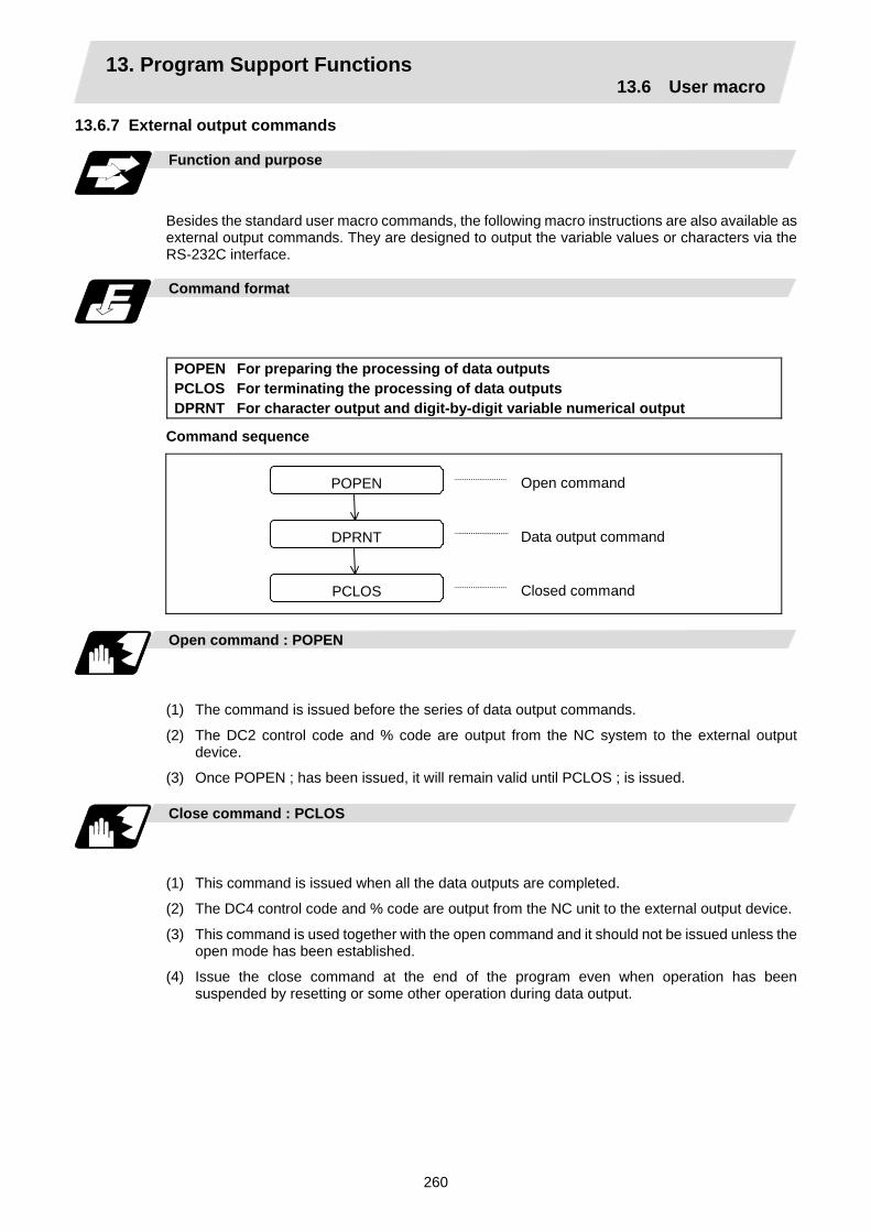
13. Program Support Functions 13.6 User macro
260
13.6.7 External output commands
Function and purpose
Besides the standard user macro commands, the following macro instructions are also available as external output commands. They are designed to output the variable values or characters via the RS-232C interface.
Command format
POPEN For preparing the processing of data outputs PCLOS For terminating the processing of data outputs DPRNT For character output and digit-by-digit variable numerical output
Command sequence
POPEN
DPRNT
PCLOS
Open command
Data output command
Closed command
Open command : POPEN
(1) The command is issued before the series of data output commands.
(2) The DC2 control code and % code are output from the NC system to the external output device.
(3) Once POPEN ; has been issued, it will remain valid until PCLOS ; is issued. Close command : PCLOS
(1) This command is issued when all the data outputs are completed.
(2) The DC4 control code and % code are output from the NC unit to the external output device.
(3) This command is used together with the open command and it should not be issued unless the open mode has been established.
(4) Issue the close command at the end of the program even when operation has been suspended by resetting or some other operation during data output.
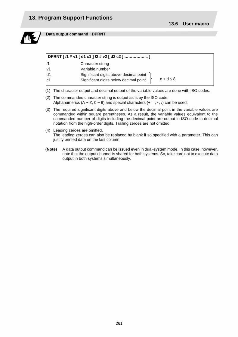
13. Program Support Functions 13.6 User macro
261
Data output command : DPRNT
DPRNT [ l1 # v1 [ d1 c1 ] l2 # v2 [ d2 c2 ] ……………... ]
l1 v1
Character string Variable number
d1 c1
Significant digits above decimal pointSignificant digits below decimal point
c + d ≤ 8
(1) The character output and decimal output of the variable values are done with ISO codes.
(2) The commanded character string is output as is by the ISO code. Alphanumerics (A ~ Z, 0 ~ 9) and special characters (+, −, ∗, /) can be used.
(3) The required significant digits above and below the decimal point in the variable values are commanded within square parentheses. As a result, the variable values equivalent to the commanded number of digits including the decimal point are output in ISO code in decimal notation from the high-order digits. Trailing zeroes are not omitted.
(4) Leading zeroes are omitted. The leading zeroes can also be replaced by blank if so specified with a parameter. This can
justify printed data on the last column.
(Note) A data output command can be issued even in dual-system mode. In this case, however, note that the output channel is shared for both systems. So, take care not to execute data output in both systems simultaneously.
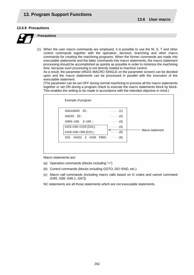
13. Program Support Functions 13.6 User macro
262
13.6.8 Precautions
Precautions
(1) When the user macro commands are employed, it is possible to use the M, S, T and other
control commands together with the operation, decision, branching and other macro commands for creating the machining programs. When the former commands are made into executable statements and the latter commands into macro statements, the macro statement processing should be accomplished as quickly as possible in order to minimize the machining time, because such processing is not directly related to machine control. As a result, the parameter (#8101 MACRO SINGLE on the parameter screen) can be decided upon and the macro statements can be processed in parallel with the execution of the executable statement. (The parameter can be set OFF during normal machining to process all the macro statements together or set ON during a program check to execute the macro statements block by block. This enables the setting to be made in accordance with the intended objective in mind.)
Example of program
G91G28X0 Z0 ; ⋅ ⋅ ⋅ ⋅ ⋅ ⋅(1)
G92X0 Z0 ; ⋅ ⋅ ⋅ ⋅ ⋅ ⋅(2)
G00X–100. Z–100. ; ⋅ ⋅ ⋅ ⋅ ⋅ ⋅(3)
#101=100.∗COS [210,] ; ⋅ ⋅ ⋅ ⋅ ⋅ ⋅(4)
#103=100.∗SIN [210.] ; ⋅ ⋅ ⋅ ⋅ ⋅ ⋅(5)
G01 X#101 Z #103 F800 ; ⋅ ⋅ ⋅ ⋅ ⋅ ⋅(6)
Macro statement
Macro statements are:
(a) Operation commands (blocks including "=")
(b) Control commands (blocks including GOTO, DO~END, etc.)
(c) Macro call commands (including macro calls based on G codes and cancel command (G65. G66. G66.1, G67))
NC statements are all those statements which are not executable statements.
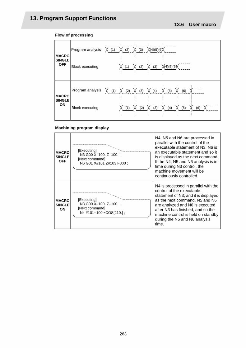
13. Program Support Functions 13.6 User macro
263
Flow of processing
MACRO SINGLE
OFF
Program analysis
Block executing
(1) (2) (4)(5)(6)(3)
(1) (2) (4)(5)(6) (3)
MACRO SINGLE
ON
Program analysis
Block executing
(1) (2) (3)
(1) (2) (3)
(4) (5) (6)
(4) (5) (6)
Machining program display
MACRO SINGLE
OFF
[Executing] N3 G00 X–100. Z–100. ; [Next command] N6 G01 X#101 Z#103 F800 ;
N4, N5 and N6 are processed in parallel with the control of the executable statement of N3. N6 is an executable statement and so it is displayed as the next command. If the N4, N5 and N6 analysis is in time during N3 control, the machine movement will be continuously controlled.
MACRO SINGLE
ON
[Executing] N3 G00 X–100. Z–100. ; [Next command] N4 #101=100.∗COS[210.] ;
N4 is processed in parallel with the control of the executable statement of N3, and it is displayed as the next command. N5 and N6 are analyzed and N6 is executed after N3 has finished, and so the machine control is held on standby during the N5 and N6 analysis time.

13. Program Support Functions 13.7 Corner chamfering/corner rounding I
264
13.7 Corner chamfering/corner rounding I
Chamfering at any angle or corner rounding is performed automatically by adding ",C_" or ",R_" to the end of the block to be commanded first among those command blocks which shape the corner with lines only.
13.7.1 Corner chamfering ",C"
Function and purpose
The corner is chamfered in such a way that the positions produced by subtracting the lengths commanded by ",C_" (or "I_", "K_", "C_") from the hypothetical starting and final corners which would apply if no chamfering were to be performed, are connected.
Command format
N100 G01 X__ Z__ ,C__ ; N200 G01 X__ Z__ ; ,C_ Length up to chamfering starting point or end point from hypothetical
corner
Chamfering is performed at the point where N100 and N200 intersect.
Example of program
G01 W100. ,C10. F100 ; U280. W100. ;
100.0 100.0
10.0
10.0
140
Z axis
Chamferingend point
Hypothetical cornerintersection point
Chamfering start point
X axis
13. Program Support Functions 13.7 Corner chamfering/corner rounding I
265
Detailed description
(1) The start point of the block following the corner chamfering serves as the hypothetical corner
intersection point.
(2) When the comma in ",C" is not present, it is handled as a C command.
(3) When both corner chamfering and corner rounding are commanded in the same block, the latter command is valid.
(4) Tool offset is calculated for the shape which has already been subjected to corner chamfering.
(5) When the block following a command with corner chamfering does not contain a linear command, a corner chamfering/corner rounding II function results.
(6) Program error (P383) results when the movement amount in the block commanding corner chamfering is less than the chamfering amount.
(7) Program error (P384) results when the movement amount in the block following the block commanding corner chamfering is less than the chamfering amount.
(8) A program error (P382) results when a movement command is not issued in the block following the corner chamfering I command.

13. Program Support Functions 13.7 Corner chamfering/corner rounding I
266
13.7.2 Corner rounding ",R_"
Function and purpose
Corner rounding of the hypothetical starting and final corners when corner is assumed as not rounded is performed at the radius of the arc commanded in ",R_" .
Command format
N100 G01 X__ Z__ ,R__ ; N200 G01 X__ Z__ ; ,R_ Arc radius of corner rounding
Corner rounding is performed at the point where N100 and N200 intersect.
Example of program
G01 W100. ,R10. F100 ; U280. W100. ;
100.0 100.0
140
R10.0
Corner rounding end point
Corner roundingstart point
Hypothetical corner intersection point
Z axis
X axis

13. Program Support Functions 13.7 Corner chamfering/corner rounding I
267
Detailed description
(1) The start point of the block following the corner rounding serves as the hypothetical corner
intersection point.
(2) When the comma in ",R" is not present, it is handled as an R command.
(3) When both corner chamfering and corner rounding are commanded in the same block the latter command is valid.
(4) Tool offset is calculated for the shape which has already been subjected to corner rounding.
(5) When the block following a command with corner rounding does not contain a linear command, a corner chamfering/corner rounding II function results.
(6) Program error (P383) results when the movement amount in the block commanding corner rounding is less than the R value.
(7) Program error (P384) results when the movement amount in the block following corner rounding is less than the R value.
(8) A program error (P382) will occur if a movement command is not issued in the block following corner rounding.
13.7.3 Interrupt during corner chamfering/corner rounding
Detailed description
(1) The operations are shown below for manual interrupt during corner chamfering or corner
rounding.
With an absolute value command and manual absolute switch ON.
20.
X
40.
140.
Z
N4N3
70. 120. (Unit: mm)
N1 G28 XZ ; N2 G00 X40. Z120. ; N3 G03 X140. Z70. K−50. ,R20. F100 ;N4 G01 X40. Z20. ; : Z-axis interrupt
Wheninterrupt is applied
X-axis interrupt
When interrupt is not applied

13. Program Support Functions 13.7 Corner chamfering/corner rounding I
268
With an incremental value command and manual absolute switch OFF
20.
X
40.
140.
Z70. 120.
N4 N3
(Unit: mm)
N1 G28 XZ ; N2 G00 U40. W120. ; N3 G03 U100. W−50. K−50. ,R20. F100 ; N4 G01 U−100. W−50. ;
: Z-axis interrupt
When interruptis applied
X-axis interrupt
When interrupt is not applied
(2) With a single block during corner chamfering or corner rounding, the tool stops after corner chamfering or corner rounding is executed.

13. Program Support Functions 13.8 Corner chamfering/corner rounding II
269
13.8 Corner chamfering/corner rounding II
In a block that forms a corner with continuous random angle lines or arcs, corner chamfering and corner rounding can be performed by adding ",C" or ",R" to the end of the block commanded first. Corner chamfering and corner rounding can both be commanded as an absolute value or incremental value.
13.8.1 Corner chamfering ",C_"
Function and purpose
The corner is chamfered by commanding ",C" in the 1st block of two blocks having continuous arcs. For an arc, this will be the chord length.
Command format
N100 G03 X__ Z__ K__ ,C__ ; N200 G01 X__ Z__ ; ,C_ Length up to chamfering starting point or end point from hypothetical
corner
Corner chamfering is performed at the point where N100 and N200 intersect.
Example of program
(1) Linear – arc
Absolute value command N1 G28 X Z ; N2 G00 X50. Z100. ; N3 G01 X150. Z50. ,C20. F100 ; N4 G02 X50. Z0 I0 K–50. ;
: Relative value command
N1 G28 X Z ; N2 G00 U25. W100. ; N3 G01 U50. W–50. ,C20. F100 ; N4 G02 U–50. W–50. I0 K–50. ;
:
(Unit: mm)
X
Z
Hypothetical corner intersection point
N4
100.50
150
50
N3
C20.C20.

13. Program Support Functions 13.8 Corner chamfering/corner rounding II
270
Detailed description
(1) The corner chamfering and corner rounding options are required to use this function.
(2) The start point of the block following the corner chamfering serves as the hypothetical corner intersection point.
(3) When the comma in ",C" is not present, it is handled as a C command.
(4) If there are multiple or duplicate corner chamfering commands in the same block, the command issued last will be valid.
(5) When both corner chamfering and corner rounding are commanded in the same block, the latter command is valid.
(6) Tool offset is calculated for the shape which has already been subjected to corner chamfering.
(7) A program error (P385) results when positioning or thread cutting is commanded in the corner chamfering command block or next block.
(8) A program error (P382) results when the block following corner chamfering contains a G command other than group 01 or another command.
(9) Program error (P383) results when the movement amount in the block commanding corner chamfering is less than the chamfering amount.
(10) Program error (P384) results when the movement amount in the block following the block commanding corner chamfering is less than the chamfering amount.
(11) Even if a diameter is commanded, it will be handled as a radius value during corner chamfering.
(12) A program error (P382) results when a movement command is not issued in the block following the corner chamfering II command.
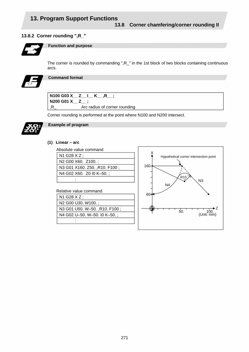
13. Program Support Functions 13.8 Corner chamfering/corner rounding II
271
13.8.2 Corner rounding ",R_"
Function and purpose
The corner is rounded by commanding ",R_" in the 1st block of two blocks containing continuous arcs.
Command format
N100 G03 X__ Z__ I__ K__ ,R__ ; N200 G01 X__ Z__ ; ,R_ Arc radius of corner rounding
Corner rounding is performed at the point where N100 and N200 intersect.
Example of program
(1) Linear – arc Absolute value command N1 G28 X Z ; N2 G00 X60. Z100. ; N3 G01 X160. Z50. ,R10. F100 ; N4 G02 X60. Z0 I0 K–50. ; : Relative value command N1 G28 X Z ; N2 G00 U30. W100. ; N3 G01 U50. W–50. ,R10. F100 ; N4 G02 U–50. W–50. I0 K–50. ; :
(Unit: mm)
X
Z
Hypothetical corner intersection point
N4
50.
160.
60.
N3
100.
R10.
13. Program Support Functions 13.8 Corner chamfering/corner rounding II
272
Detailed description
(1) The corner chamfering and corner rounding options are required to use this function.
(2) The start point of the block following the corner rounding serves as the hypothetical corner intersection point.
(3) When the comma in ",R" is not present, it is handled as an R command.
(4) When both corner chamfering and corner rounding are commanded in the same block the latter command is valid.
(5) Tool offset is calculated for the shape which has already been subjected to corner rounding.
(6) A program error (P385) results when positioning or thread cutting is commanded in the corner rounding command block or next block.
(7) A program error (P382) results when the block following corner rounding contains a G command other than group 01 or another command.
(8) Program error (P383) results when the movement amount in the block commanding corner rounding is less than the R value.
(9) Program error (P384) results when the movement amount in the block following the block commanding corner rounding is less than the R value.
(10) Even if a diameter is commanded, it will be handled as a radius value during corner rounding.
(11) A program error (P382) results when a movement command is not issued in the block following corner rounding II.
13.8.3 Interrupt during corner chamfering/corner rounding Refer to section "13.7.3 Interrupt during corner chamfering/corner rounding" for details.
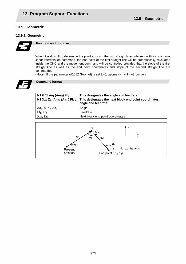
13. Program Support Functions 13.9 Geometric
273
13.9 Geometric 13.9.1 Geometric I Function and purpose
When it is difficult to determine the point at which the two straight lines intersect with a continuous linear interpolation command, the end point of the first straight line will be automatically calculated inside the CNC and the movement command will be controlled provided that the slope of the first straight line as well as the end point coordinates and slope of the second straight line are commanded. (Note) If the parameter (#1082 Geomet) is set to 0, geometric I will not function.
Command format
N1 G01 Aa1 (A–a2) Ff1 ; N2 Xx2 Zz2 A–a2 (Aa3 ) Ff2 ;
This designates the angle and feedrate. This designates the next block end point coordinates, angle and feedrate.
Aa1, A–a2, Aa3
Ff1, Ff2
Xx2, Zz2
Angle Feedrate Next block end point coordinates
a1
X
Z N1 N2a2
a3
a1
(Z2,X2)Present position
Horizontal axis
?
End point
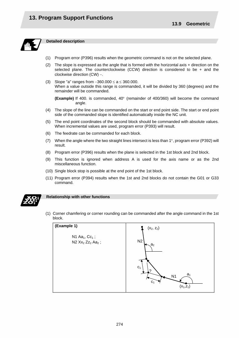
13. Program Support Functions 13.9 Geometric
274
Detailed description
(1) Program error (P396) results when the geometric command is not on the selected plane.
(2) The slope is expressed as the angle that is formed with the horizontal axis + direction on the selected plane. The counterclockwise (CCW) direction is considered to be + and the clockwise direction (CW) −.
(3) Slope "a" ranges from −360.000 ≤ a ≤ 360.000. When a value outside this range is commanded, it will be divided by 360 (degrees) and the remainder will be commanded.
(Example) If 400. is commanded, 40° (remainder of 400/360) will become the command angle.
(4) The slope of the line can be commanded on the start or end point side. The start or end point side of the commanded slope is identified automatically inside the NC unit.
(5) The end point coordinates of the second block should be commanded with absolute values. When incremental values are used, program error (P393) will result.
(6) The feedrate can be commanded for each block.
(7) When the angle where the two straight lines intersect is less than 1°, program error (P392) will result.
(8) Program error (P396) results when the plane is selected in the 1st block and 2nd block.
(9) This function is ignored when address A is used for the axis name or as the 2nd miscellaneous function.
(10) Single block stop is possible at the end point of the 1st block.
(11) Program error (P394) results when the 1st and 2nd blocks do not contain the G01 or G33 command.
Relationship with other functions
(1) Corner chamfering or corner rounding can be commanded after the angle command in the 1st
block.
(Example 1) N1 Aa1, Cc1 ; N2 Xx2 Zz2 Aa2 ;
?
N2
N1
(x2, z2)
a2
a1
c1
c1
(x1,z1)

13. Program Support Functions 13.9 Geometric
275
(Example 2) N1 Aa1, Rr1 ; N2 Xx2 Zz2 Aa2 ;
N2
N1
(x2, z2)
a1
a2
r1
?
(x1, z1)
(2) The geometric command I can be issued after the corner chamfering or corner rounding command.
(Example 3) N1 Xx2 Zz2 ,Cc1 ; N2 Aa1 ; N3 Xx3 Zz3 Aa2 ;
N2
N1 (x2, z2)
(x3, z3) a2
a1
c1
c1
(x1, z1)
N3
?
(3) The geometric command I can be issued after the linear angle command.
(Example 4) N1 Xx2 Aa1 ; N2 Aa2 ; N3 Xx3 Zz3 Aa3 ;
N2
N1 (x2, z2)
(x3, z3) a3
a2
(x1, z1)
N3
a1
?

13. Program Support Functions 13.9 Geometric
276
13.9.2 Geometric IB Function and purpose
With the geometric IB function, the contact and intersection are obtained by commanding an arc center point or linear angle in the movement commands of two continuous blocks (only for blocks having arc commands), instead of commanding the first block end point.
Control target block (1) Two-arc contact
N2
N1
r2
r1(??)
X
Z (2) Linear - arc (arc - linear) intersection
N2
N2 N1
N1
(??)
(??) X
Z
r1
r1
(3) Linear - arc (arc - linear) contact
N2
N2
N1 N1
r1r1
(??)
X
Z
(??)
(Note) If the parameter (#1082 Geomet) is set to a value other than 2, geometric IB will not function.

13. Program Support Functions 13.9 Geometric
277
Function and purpose 1 (Automatic calculation of two-arc contact)
When the contact of two continuous contacting arcs is not indicated in the drawings, it can be automatically calculated by commanding the 1st arc center coordinate value or radius, and the 2nd arc end point absolute value and center coordinate value or radius.
Command format 1 (Automatic calculation of two-arc contact)
N1 N2
N1 N2
N1 N2
G02 (G03) G03 (G02)
G02 (G03) G03 (G02)
G02 (G03) G03 (G02)
Pp1 Qq1 Ff1 ; Xx2 Zz2 Pp2 Qq2 Ff2 ;
Pp1 Qq1 Ff1 ; Xx2 Zz2 Rr2 Ff2 ;
Rr1 Ff1 ; Xx2 Zz2 Pp2 Qq2 Ff2 ;
P, Q R
X and Z axes arc center coordinate absolute value (diameter/radius value command)The center address for the 3rd axis is commanded with A. Arc radius (when a (−) sign is attached, the arc is judged to be 180° or more)
* I and K (X and Z axes arc center coordinate incremental value) commands can be issued instead of P and Q.
1st block arc : Radius command incremental amount from the start point to the center
2nd block arc : Radius command incremental amount from the end point to the center
r2
r1
(x2, z2)
X
Z
(p2, q2)
(p1, q1)

13. Program Support Functions 13.9 Geometric
278
Detailed description 1 (Automatic calculation of two-arc contact)
(1) A program error (P393) will result before the 1st block if the 2nd block does not contain a
coordinate absolute value command.
(2) A program error (P398) will result before the 1st block if there are no geometric IB specifications.
(3) A program error (P395) will result before the 1st block if there is no R (here, the 1st block is designated with P and Q (I, K)) or P and Q (I, K) designation.
(4) A program error (P396) will result before the 1st block if another plane selection command (G17 to G19) is issued in the 2nd block.
(5) A program error (P397) will result before the 1st block if two arcs that do not contact are commanded.
(6) The contact calculation accuracy is ±1µm (fractions rounded up).
(7) Single block operation stops at the 1st block.
(8) When I or K is omitted, the values are regarded as I0 and K0. P and Q cannot be omitted.
(9) The error range in which the contact is obtained is set in parameter "#1084 RadErr".
Tool path
"Arc error"
(10) For an arc block perfect circle command (arc block start point = arc block end point), the R designation arc command finishes immediately, and there is no operation. Thus, use a PQ (IK) designation arc command.
(11) G codes of the G modal group 1 in the 1st/2nd block can be omitted.
(12) Addresses being used as axis names cannot be used as command addresses for arc center coordinates or arc radii.
(13) If the 2nd block arc inscribes the 1st arc block when the 2nd block is an R designation arc, the R+ sign becomes the inward turning arc command, and the R– sign becomes the outward turning arc command.
R–
R+
N2
N1

13. Program Support Functions 13.9 Geometric
279
Example of program 1 (Automatic calculation of two-arc contact)
(1) PQ, PQ command
N2
N1
?
80.0
80.0
60.0
50.0 50.0 20.0
Z axis
X axis
G01 X20.0 Z60.0 ; N1 G02 P50.0 Q60.0 F100 ; N2 G03 X80.0 Z30.0 P50.0 Q30.0 ; (Unit: mm)
(2) PQ, R command
30.
80.
70.
40.
N2
N1
R60.
(Unit: mm)
Z axis
X axis
G01 X40.0 Z70.0 F100 ; N1 G02 R60.0 ; N2 G03 X80.0 Z30.0 P40.0 Q30.0 ;
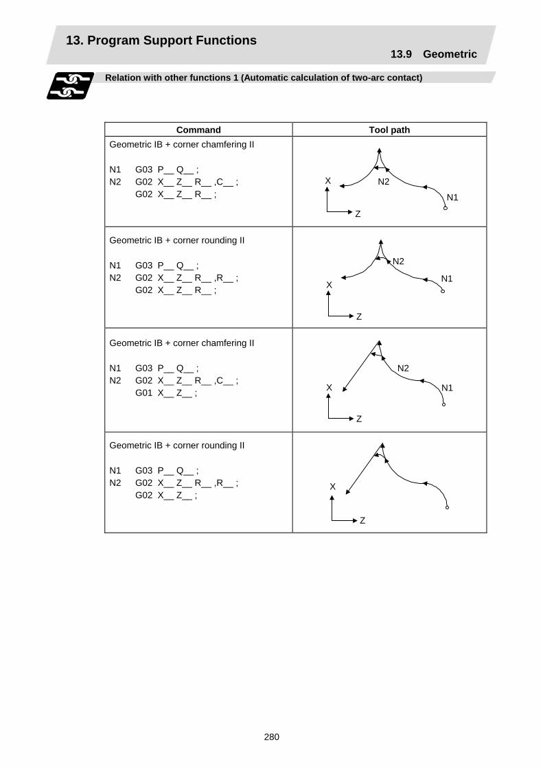
13. Program Support Functions 13.9 Geometric
280
Relation with other functions 1 (Automatic calculation of two-arc contact)
Command Tool path Geometric IB + corner chamfering II N1 G03 P__ Q__ ; N2 G02 X__ Z__ R__ ,C__ ; G02 X__ Z__ R__ ;
N2
N1
Z
X
Geometric IB + corner rounding II N1 G03 P__ Q__ ; N2 G02 X__ Z__ R__ ,R__ ; G02 X__ Z__ R__ ;
N2
N1
Z
X
Geometric IB + corner chamfering II N1 G03 P__ Q__ ; N2 G02 X__ Z__ R__ ,C__ ; G01 X__ Z__ ;
Z
X
N2
N1
Geometric IB + corner rounding II N1 G03 P__ Q__ ; N2 G02 X__ Z__ R__ ,R__ ; G02 X__ Z__ ;
Z
X

13. Program Support Functions 13.9 Geometric
281
Function and purpose 2 (Automatic calculation of linear - arc intersection)
When the intersection of a shape in which a line and arc intersect is not indicated in the drawings, it can be automatically calculated by commanding the following program.
Command format 2 (Automatic calculation of linear - arc intersection: For G18 plane)
N1 N2 N1 N2
G01 G02 (G03) G02 (G03) G01
Aa1 (A−a2) Ff1 ; Xx2 Zz2 Pp2 Qq2 Hh2 Ff2 ; Pp1 Qq1 Hh1 Ff1 ; Xx2 Zz2 Aa3 (A−a4) Ff2 ;
A P, Q
Linear angle (−360.000° to 360.000°) X and Z axes arc center coordinate absolute value (diameter/radius value command) The center address for the 3rd axis is commanded with A.
H
Linear - arc intersection selection
0 : Intersection of the shorter line 1 : Intersection of the longer line
* I and K (X and Z axes arc center coordinate incremental value) commands can be issued instead of P and Q.
1st block arc : Radius command incremental amount from the start point to the center
2nd block arc : Radius command incremental amount from the end point to the center
H=1 H=1
H=0
N2 N1
H=0
N1 a1
N2 a3
–a4 –a2
(??)
(??)
(??) (??) (p2, q2)
(x2, z2)(p1, q1)
(x2, z2)X
Z
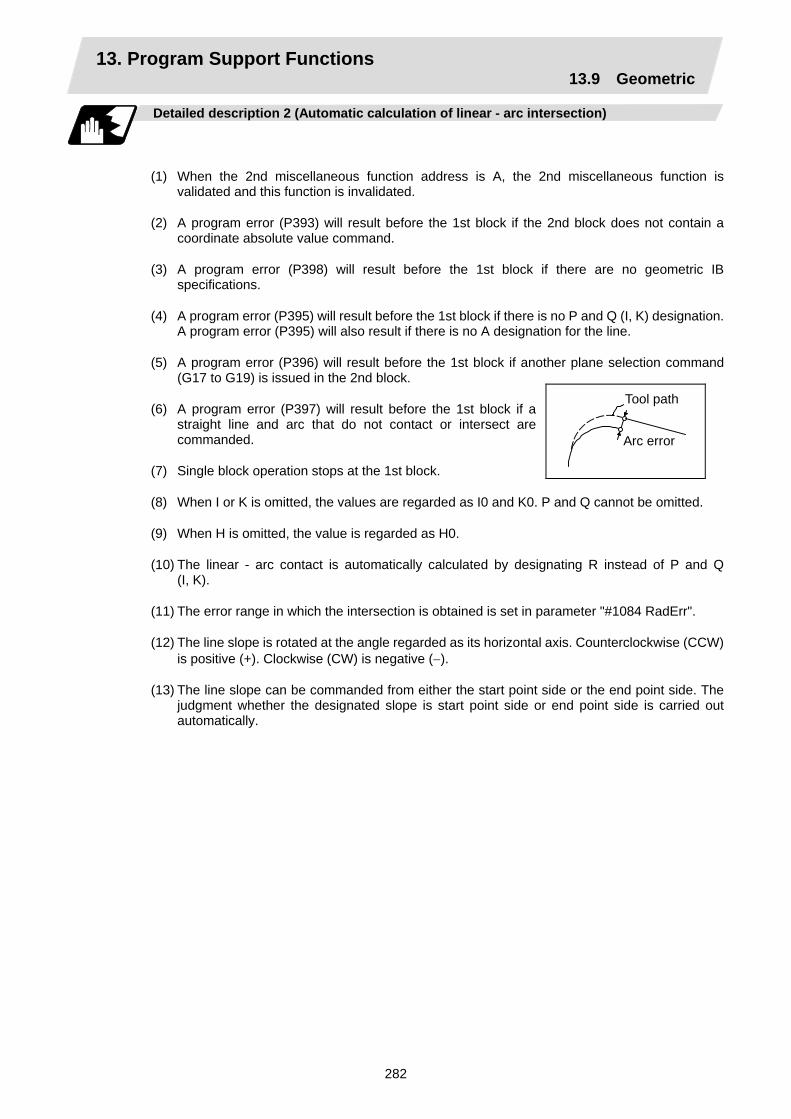
13. Program Support Functions 13.9 Geometric
282
Detailed description 2 (Automatic calculation of linear - arc intersection)
(1) When the 2nd miscellaneous function address is A, the 2nd miscellaneous function is validated and this function is invalidated.
(2) A program error (P393) will result before the 1st block if the 2nd block does not contain a coordinate absolute value command.
(3) A program error (P398) will result before the 1st block if there are no geometric IB specifications.
(4) A program error (P395) will result before the 1st block if there is no P and Q (I, K) designation. A program error (P395) will also result if there is no A designation for the line.
(5) A program error (P396) will result before the 1st block if another plane selection command (G17 to G19) is issued in the 2nd block.
(6) A program error (P397) will result before the 1st block if a straight line and arc that do not contact or intersect are commanded.
(7) Single block operation stops at the 1st block.
(8) When I or K is omitted, the values are regarded as I0 and K0. P and Q cannot be omitted.
(9) When H is omitted, the value is regarded as H0.
(10) The linear - arc contact is automatically calculated by designating R instead of P and Q (I, K).
(11) The error range in which the intersection is obtained is set in parameter "#1084 RadErr".
(12) The line slope is rotated at the angle regarded as its horizontal axis. Counterclockwise (CCW) is positive (+). Clockwise (CW) is negative (−).
(13) The line slope can be commanded from either the start point side or the end point side. The judgment whether the designated slope is start point side or end point side is carried out automatically.
Tool path
Arc error
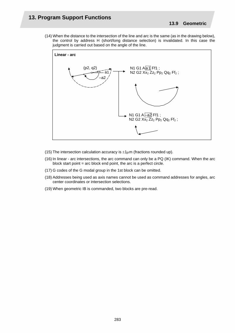
13. Program Support Functions 13.9 Geometric
283
(14) When the distance to the intersection of the line and arc is the same (as in the drawing below), the control by address H (short/long distance selection) is invalidated. In this case the judgment is carried out based on the angle of the line.
Linear - arc
N1 G1 A a1 Ff1 ;N2 G2 Xx2 Zz2 Pp2 Qq2 Ff2 ;
N1 G1 A –a2 Ff1 ;N2 G2 Xx2 Zz2 Pp2 Qq2 Ff2 ;
(p2, q2)
–a2a1
(15) The intersection calculation accuracy is ±1µm (fractions rounded up).
(16) In linear - arc intersections, the arc command can only be a PQ (IK) command. When the arc block start point = arc block end point, the arc is a perfect circle.
(17) G codes of the G modal group in the 1st block can be omitted.
(18) Addresses being used as axis names cannot be used as command addresses for angles, arc center coordinates or intersection selections.
(19) When geometric IB is commanded, two blocks are pre-read.

13. Program Support Functions 13.9 Geometric
284
Example of program 2 (Automatic calculation of linear - arc intersection)
X axis
Z axis
N2
N1
180°
100.0
50.080.0
G01 X80.0 Z50.0 F100 ; N1 G01 A180.0 ; N2 G03 X100.0 Z0 P0 Q0 ;
?
(Unit: mm)

13. Program Support Functions 13.9 Geometric
285
Relation with other functions 2 (Automatic calculation of linear - arc intersection)
Command Tool path
Geometric IB + corner chamfering II N1 G01 A__ ,C__ ; N2 G03 X__ Z__ P__ Q__ H__ ;
N2
N1
Z
X
Geometric IB + corner rounding II N1 G01 A__ ,R__ ; N2 G03 X__ Z__ P__ Q__ H__ ;
N2
N1 Z
X
Geometric IB + corner chamfering II N1 G01 A__ ; N2 G03 X__ Z__ P__ Q__ H__ ,C__ ; G01 X__ Z__ ;
N2
N1 Z
X
Geometric IB + corner rounding II N1 G01 A__ ; N2 G03 X__ Z__ P__ Q__ H__ ,R__ ; G01 X__ Z__ ;
N2N1
Z
X
Geometric IB + corner chamfering II N1 G02 P__ Q__ H__ ; N2 G01 X__ Z__ A__ ,C__ ; G01 X__ Z__ ;
N2
N1 Z
X
Geometric IB + corner rounding II N1 G02 P__ Q__ H__ ; N2 G01 X__ Z__ A__ ,R__ ; G01 X__ Z__ ;
N2
N1 Z
X

13. Program Support Functions 13.9 Geometric
286
Function and purpose 3 (Automatic calculation of linear - arc intersection)
When the contact of a shape in which a line and arc contact is not indicated in the drawings, it can be automatically calculated by commanding the following program.
Command format 3 (Automatic calculation of linear - arc intersection: For G18 plane)
N1 N2
N1 N2
G0 G03 (G02)
G03 (G02) G01
Aa1 (A−a2) Ff1 ; Xx2 Zz2 Rr2 ;
Rr2 Ff1 ; Xx2 Zz2 Aa3 (A−a4) Ff2 ;
A
R
Linear angle (−360.000° to 360.000°)
Arc radius
X
Z
N1
(x2, z2)
(??) N1N2
N2(x2, z2)
(??)
a3
–a4
–a2 r2r1
a1

13. Program Support Functions 13.9 Geometric
287
Detailed description 3 (Automatic calculation of linear - arc intersection)
(1) When the 2nd miscellaneous function address is A, the 2nd miscellaneous function is validated and this function is invalidated.
(2) A program error (P393) will result before the 1st block if the 2nd block does not contain a coordinate absolute value command.
(3) A program error (P398) will result before the 1st block if there are no geometric IB specifications.
(4) A program error (P396) will result before the 1st block if another plane selection command (G17 to G19) is issued in the 2nd block.
(5) A program error (P397) will result before the 1st block if a straight line and arc that do not contact are commanded.
(6) A program error (P395) will result before the 1st block if there is no R designation for the 2nd block. A program error (P395) will also result if there is no A designation for the line.
(7) Single block operation stops at the 1st block.
(8) The linear - arc intersection is automatically calculated by designating R instead of P and Q (I, K).
(9) The error range in which the contact is obtained is set in parameter "#1084 RadErr".
(10) The line slope is rotated at the angle regarded as the positive (+) direction of its horizontal axis. Counterclockwise (CCW) is positive (+). Clockwise (CW) is negative (−).
(11) The line slope can be commanded from either the start point side or the end point side. The judgment whether the designated slope is start point side or end point side is carried out automatically.
(12) The intersection calculation accuracy is ± 1µm (fractions rounded up).
(13) In linear - arc contact, the arc command can only be an R command. Thus, when the arc block start point = arc block end point, the arc command finishes immediately, and there is no operation. (Perfect circle commands are not possible.)
(14) G codes of the G modal group 1 in the 1st block can be omitted.
(15) Addresses being used as axis names cannot be used as command addresses for angles or arc radii.
(16) When geometric IB is commanded, two blocks are pre-read.
Tool path
Arc error

13. Program Support Functions 13.9 Geometric
288
Example of program 3 (Automatic calculation of linear - arc intersection)
N1
?
100.050.0
50.0
135°
40.0
N2
(Unit: mm)
Z axis
X axis
G01 X40.0 Z50.0 F100 ; N1 G01 A135.0 ; N2 G03 X100.0 Z0.0 R50.0 ;

13. Program Support Functions 13.9 Geometric
289
Relation with other functions 3 (Automatic calculation of linear - arc intersection)
Command Tool path Geometric IB + corner chamfering N1 G03 R__ ; N2 G01 X__ Z__ A__ ,C__ ; G01 X__ Z__ R__ ;
Z
X
Geometric IB + corner rounding N1 G03 R__ ; N2 G01 X__ Z__ A__ ,R__ ; G01 X__ Z__ ;
Z
X
Geometric IB + corner chamfering II N1 G01 A__ ; N2 G02 X__ Z__ R__ ,C__ ; G01 X__ Z__ ;
Z
X
Geometric IB + corner rounding II N1 G01 A__ ; N2 G02 X__ Z__ R__ ,R__ ; G01 X__ Z__ ;
Z
X

13. Program Support Functions 13.10 Program parameter input
290
13.10 Program parameter input; G10, G11 Function and purpose
The parameters set from the setting and display unit can be changed in the machining programs. The data format used for the data setting is as follows.
Command format
G10 L50 ; Data setting command P major classification number N data number H bit type data ; P major classification number A axis number N data number D byte type data ; P major classification number A axis number N data number S word type data ; P major classification number A axis number N data number L 2 word type data ; G11 ; Data setting mode cancel (data setting completed)
There are 8 types of data formats according to the type of parameter (axis-common and axis- independent) and data type, as listed below.
With axis-common data Axis-common bit-type parameter Axis-common byte-type parameter Axis-common word-type parameter Axis-common 2-word-type parameter
With axis-independent data Axis-independent bit-type parameter Axis-independent byte-type parameter Axis-independent word-type parameter Axis-independent 2-word-type parameter
P N H ; P N D ; P N S ; P N L ; P A N H ; P A N D ; P A N S ; P A N L ;
(Note 1) The sequence of addresses in a block must be as shown above.
(Note 2) Whether the parameter value is replaced or added depends on the modal state of G90/G91 when G10 is commanded.
(Note 3) Refer to Appendix Table 1 for the P, N number correspondence table.
(Note 4) For a bit type parameter, the data type will be H ( is a value between 0 and 7).
(Note 5) The axis number is set in the following manner: 1st axis is 1, 2nd axis is 2, and so forth. When using multiple part system, the 1st axis in each part system is set as 1, the second
axis is set as 2, and so forth. (Note 6) Command G10L50, L11 in independent blocks. A program error (P33, P421) will occur if
not commanded in independent blocks.
Example of program
(Example) To turn ON bit 2 of bit selection #6401 G10 L50 ; P8 N1 H21 ; G11 ;

13. Program Support Functions 13.11 Macro interrupt
291
13.11 Macro interrupt ; M96, M97
Function and purpose
A user macro interrupt signal (UIT) is input from the machine to interrupt the program being currently executed and instead call another program and execute it. This is called the user macro interrupt function. Use of this function allows the program to operate flexibly enough to meet varying conditions. For setting the parameters of this function, refer to the Operating Manual.
Command format
M96 P__ H__ ; M97 ; P H
User macro interrupt enable User macro interrupt disable Interrupt program number Interrupt sequence number
The user macro interrupt function is enabled and disabled by the M96 and M97 commands programmed to make the user macro interrupt signal (UIT) valid or invalid. That is, if an interrupt signal (UIT) is input from the machine side in a user macro interrupt enable period from when M96 is issued to when M97 is issued or the NC is reset, a user macro interrupt is caused to execute the program specified by P__ instead of the one being executed currently. Another interrupt signal (UIT) is ignored while one user macro interrupt is being in service. It is also ignored in a user macro interrupt disable state such as after an M97 command is issued or the system is reset. M96 and M97 are processed internally as user macro interrupt control M codes.
Interrupt enable conditions
A user macro interrupt is enabled only during execution of a program. The requirements for the user macro interrupt are as follows:
(1) A memory operation mode or MDI has been selected.
(2) The system is running in automatic mode.
(3) No user macro interrupt is being processed.
(Note 1) A macro interrupt is disabled in manual operation mode (JOG, STEP, HANDLE, etc.)

13. Program Support Functions 13.11 Macro interrupt
292
Outline of operation
(1) When a user macro interrupt signal (UIT) is input after an M96 Pp1 ; command is issued by the
current program, interrupt program Op1 is executed. When an M99 ; command is issued by the interrupt program, control returns to the main program.
(2) If M99 Pp2 ; is specified, the blocks from the one next to the interrupted block to the last one are searched for the block with sequence number Np2 ;. Control thus returns to the block with sequence number Np2 ; that is found first in the above search.
Interrupt signal (UIT)not acceptable withina user macro program
M96 Pp1 ;
Np2 ;
M97 ;
Np2 ;
Op1 ;
M99 (Pp2) ;
(If Pp2 is specified)
User macrointerrupt signal (UIT)
Current program
Interrupt program

13. Program Support Functions 13.11 Macro interrupt
293
Interrupt type
Interrupt types 1 and 2 can be selected by the parameter "#1113 INT_2". [Type 1] • When an interrupt signal (UIT) is input, the system immediately stops moving the tool and
interrupts dwell, then permits the interrupt program to run.
• If the interrupt program contains a move or miscellaneous function (MSTB) command, the commands in the interrupted block are lost. After the interrupt program completes, the main program resumes operation from the block next to the interrupted one.
• If the interrupted program contains no move and miscellaneous (MSTB) commands, it resumes operation, after completion of the interrupt program, from the point in the block where the interrupt was caused.
If an interrupt signal (UIT) is input during execution of a miscellaneous function (MSTB) command, the NC system waits for a completion signal (FIN). The system thus executes a move or miscellaneous function (MSTB) command in the interrupt program only after input of FIN.
[Type 2] • When an interrupt signal (UIT) is input, the program completes the commands in the current
block, then transfers control to the interrupt program.
• If the interrupt program contains no move and miscellaneous function (MSTB) commands, the interrupt program is executed without interrupting execution of the current program.
However, if the interrupt program has not ended even after the execution of the original block is completed, the system may stop machining temporarily.

13. Program Support Functions 13.11 Macro interrupt
294
block (2)
User macro interruptsignal
block (2) block (2)
block (2)Main program
block (1) block (3)
block (1) block (3)
block (1) block (3)
[Type 1]
[Type 2]
block (2)Main program
block (1) block (3)
block (1)
Interrupt program
Interrupt program
block (1)
block (2)
block (2)
block (3)
block (3)
User macrointerrupt signal
Interrupt program
Executing
If the interrupt program contains a move or miscellaneous function command, the reset of block (2) is lost.
If the interrupted program contains nomove and miscellaneous commands, it resumes operation from where it left inblock (2), that is, all the reset commands.
Interrupt program
User macro interruptsignal
If the interrupted program contains nomove and miscellaneous commands,the interrupted program is kept executed in parallel to execution of thecurrent program.
The move or miscellaneous command in the interrupt program isexecuted after completion of the current block.
User macrointerrupt signal
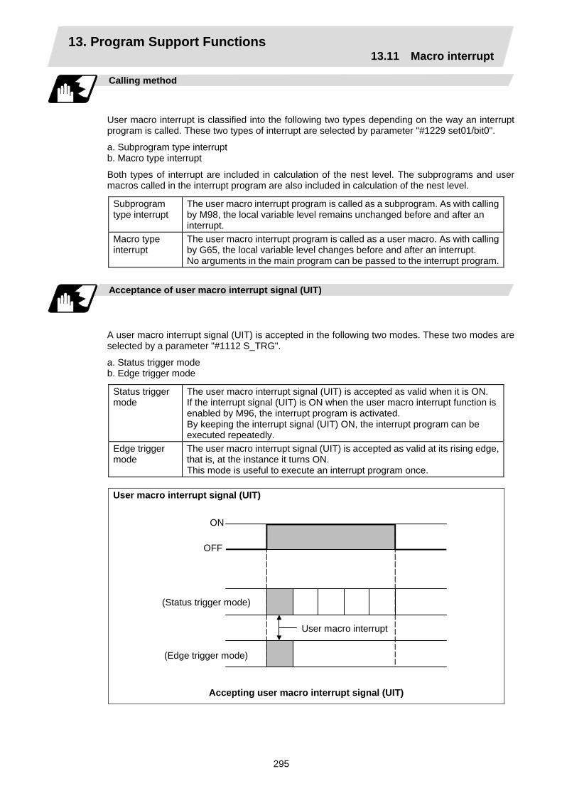
13. Program Support Functions 13.11 Macro interrupt
295
Calling method
User macro interrupt is classified into the following two types depending on the way an interrupt program is called. These two types of interrupt are selected by parameter "#1229 set01/bit0".
a. Subprogram type interrupt b. Macro type interrupt
Both types of interrupt are included in calculation of the nest level. The subprograms and user macros called in the interrupt program are also included in calculation of the nest level.
Subprogram type interrupt
The user macro interrupt program is called as a subprogram. As with calling by M98, the local variable level remains unchanged before and after an interrupt.
Macro type interrupt
The user macro interrupt program is called as a user macro. As with calling by G65, the local variable level changes before and after an interrupt. No arguments in the main program can be passed to the interrupt program.
Acceptance of user macro interrupt signal (UIT)
A user macro interrupt signal (UIT) is accepted in the following two modes. These two modes are selected by a parameter "#1112 S_TRG".
a. Status trigger mode b. Edge trigger mode
Status trigger mode
The user macro interrupt signal (UIT) is accepted as valid when it is ON. If the interrupt signal (UIT) is ON when the user macro interrupt function is enabled by M96, the interrupt program is activated. By keeping the interrupt signal (UIT) ON, the interrupt program can be executed repeatedly.
Edge trigger mode
The user macro interrupt signal (UIT) is accepted as valid at its rising edge, that is, at the instance it turns ON. This mode is useful to execute an interrupt program once.
User macro interrupt signal (UIT)
ON
OFF
(Status trigger mode)
User macro interrupt
(Edge trigger mode)
Accepting user macro interrupt signal (UIT)

13. Program Support Functions 13.11 Macro interrupt
296
Returning from user macro interrupt
M99 (P__) ;
An M99 command is issued in the interrupt program to return to the main program. Address P is used to specify the sequence number of the return destination in the main program. The blocks from the one next to the interrupted block to the last one in the main program are first searched for the block with sequence number Np2 ;. If it is not found, all the blocks before the interrupted one are then searched. Control thus returns to the block with sequence number Np2 ; that is found first in the above search. (This is equivalent to M99 P__ used after M98 calling.)
Modal information affected by user macro interrupt
If modal information is changed by the interrupt program, it is handled as follows after control returns from the interrupt program to the main program.
Returning with M99 ;
The change of modal information by the interrupt program is invalidated and the original modal information is not restored. With interrupt type 1, however, if the interrupt program contains a move or miscellaneous function (MSTB) command, the original modal information is not restored.
Returning with M99 P__ ;
The original modal information is updated by the change in the interrupt program even after returning to the main program. This is the same as in returning with M99 P__ ; from a program called by M98.
Modal modifiedby interrupt program remainseffective.
User macro interrupt signal (UIT)
Interrupt program
M96 Pp1 ; Op1 ;
M99 (p2) ;
Np2 ;
(Modal change)
Modal beforeinterrupt is restored.
Main program being executed
(With Pp2 specified)
Modal information affected by user macro interrupt
13. Program Support Functions 13.11 Macro interrupt
297
Modal information variables (#4401 to #4520)
Modal information when control passes to the user macro interrupt program can be known by reading system variables #4401 to #4520. The unit specified with a command applies.
System variable Modal information
#4401 ~ #4421 G code (group 01 to group 21) Some groups are not used.#4507 D code #4509 F code #4511 H code #4513 M code #4514 Sequence number #4515 Program number #4519 S code #4520 T code
The above system variables are available only in the user macro interrupt program. If they are used in other programs, program error (P241) results.
M code for control of user macro interrupt
The user macro interrupt is controlled by M96 and M97. However, these commands may have been used for other operation. To be prepared for such case, these command functions can be assigned to other M codes. (This invalidates program compatibility.) User macro interrupt control with alternate M codes is possible by setting the alternate M code in parameters "#1110 M96_M" and "#1111 M97_M" and by validating the setting by selecting parameter "#1109 subs_M". (M codes 03 to 97 except 30 are available for this purpose.) If the parameter "#1109 subs_M" used to enable the alternate M codes is not selected, the M96 and M97 codes remain effective for user macro interrupt control. In either case, the M codes for user macro interrupt control are processed internally and not output to the outside.

13. Program Support Functions 13.11 Macro interrupt
298
Parameters
Refer to the Instruction Manual for details on the setting methods.
(1) Subprogram call validity "#1229 set01/bit 0"
1 : Subprogram type user macro interrupt 0 : Macro type user macro interrupt
(2) Status trigger mode validity "#1112 S_TRG"
1 : Status trigger mode 0 : Edge trigger mode
(3) Interrupt type 2 validity "#1113 INT_2"
1 : The executable statements in the interrupt program are executed after completion of execution of the current block. (Type 2)
0 : The executable statements in the interrupt program are executed before completion of execution of the current block. (Type 1)
(4) Validity of alternate M code for user macro interrupt control "#1109 subs_M"
1 : Valid 0 : Invalid
(5) Alternate M codes for user macro interrupt
Interrupt enable M code (equivalent to M96) "#1110 M96_M" Interrupt disable M code (equivalent to M97) "#1111 M97_M" M codes 03 to 97 except 30 are available.
Restrictions
(1) If the user macro interrupt program uses system variables #5001 and after (position
information) to read coordinates, the coordinates pre-read in the buffer are used.
(2) If an interrupt is caused during execution of the tool diameter compensation, a sequence number (M99 P__ ;) must be specified with a command to return from the user macro interrupt program. If no sequence number is specified, control cannot return to the main program normally.
13. Program Support Functions 13.12 Tool change position return
299
13.12 Tool change position return; G30.1 ~ G30.5
Function and purpose
By specifying the tool change position in a parameter "#8206 tool change" and also specifying a tool change position return command in a machining program, the tool can be changed at the most appropriate position. The axes that are going to return to the tool change position and the order in which the axes begin to return can be changed by commands.
Command format
(1) The format of tool change position return commands is as follows.
G30.n ; n = 1 to 5 Specify the axes that return to the tool change position and the order in which
they return.
Commands and return order
Command Return order G30.1 X axis only ( → additional axis) G30.2 Z axis only ( → additional axis) G30.3 X axis → Z axis ( → additional axis) G30.4 Z axis → X axis ( → additional axis) G30.5 X axis • Z axis ( → additional axis)
(Note 1) An arrow ( → ) indicates the order of axes that begin to return. A period ( • ) indicates that the axes begin to return simultaneously. Example : "Z axis → X axis" indicate that the Z axis returns to the tool change
position, then the X axis does.
(2) The tool change position return on/off for the additional axis can be set with parameter "#1092 Tchg_A" for the additional axis. For the order for returning to the tool change position, the axes return after the standard axis completes the return to the tool change position (refer to above table). For specifications having two additional axes, the two additional axes simultaneously return to the tool change position after the standard axis has finished its return to the tool change position.
The additional axis alone cannot return to the tool change position.
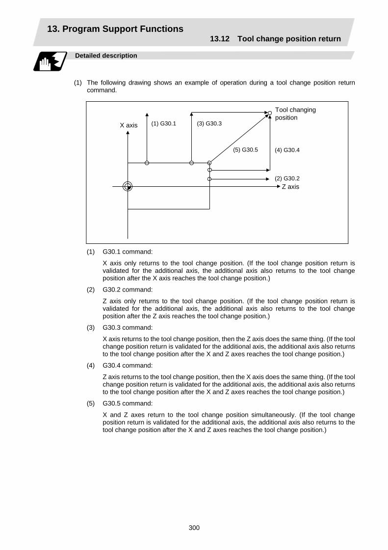
13. Program Support Functions 13.12 Tool change position return
300
Detailed description
(1) The following drawing shows an example of operation during a tool change position return
command.
(1) G30.1 (3) G30.3
(5) G30.5 (4) G30.4
(2) G30.2
Tool changing position
X axis
Z axis
(1) G30.1 command:
X axis only returns to the tool change position. (If the tool change position return is validated for the additional axis, the additional axis also returns to the tool change position after the X axis reaches the tool change position.)
(2) G30.2 command:
Z axis only returns to the tool change position. (If the tool change position return is validated for the additional axis, the additional axis also returns to the tool change position after the Z axis reaches the tool change position.)
(3) G30.3 command:
X axis returns to the tool change position, then the Z axis does the same thing. (If the tool change position return is validated for the additional axis, the additional axis also returns to the tool change position after the X and Z axes reaches the tool change position.)
(4) G30.4 command:
Z axis returns to the tool change position, then the X axis does the same thing. (If the tool change position return is validated for the additional axis, the additional axis also returns to the tool change position after the X and Z axes reaches the tool change position.)
(5) G30.5 command:
X and Z axes return to the tool change position simultaneously. (If the tool change position return is validated for the additional axis, the additional axis also returns to the tool change position after the X and Z axes reaches the tool change position.)
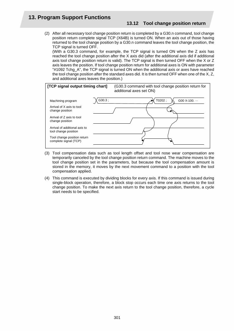
13. Program Support Functions 13.12 Tool change position return
301
(2) After all necessary tool change position return is completed by a G30.n command, tool change position return complete signal TCP (X64B) is turned ON. When an axis out of those having returned to the tool change position by a G30.n command leaves the tool change position, the TCP signal is turned OFF.
(With a G30.3 command, for example, the TCP signal is turned ON when the Z axis has reached the tool change position after the X axis did (after the additional axis did if additional axis tool change position return is valid). The TCP signal is then turned OFF when the X or Z axis leaves the position. If tool change position return for additional axes is ON with parameter "#1092 Tchg_A", the TCP signal is turned ON when the additional axis or axes have reached the tool change position after the standard axes did. It is then turned OFF when one of the X, Z, and additional axes leaves the position.)
[TCP signal output timing chart] (G30.3 command with tool change position return for additional axes set ON)
Machining program
Arrival of X axis to tool change position
Arrival of Z axis to tool change position
Arrival of additional axis to tool change position
Tool change position return complete signal (TCP)
G30.3 ; T0202 ; G00 X-100. ···
(3) Tool compensation data such as tool length offset and tool nose wear compensation are temporarily canceled by the tool change position return command. The machine moves to the tool change position set in the parameters, but because the tool compensation amount is stored in the memory, it moves by the next movement command to a position with the tool compensation applied.
(4) This command is executed by dividing blocks for every axis. If this command is issued during single-block operation, therefore, a block stop occurs each time one axis returns to the tool change position. To make the next axis return to the tool change position, therefore, a cycle start needs to be specified.
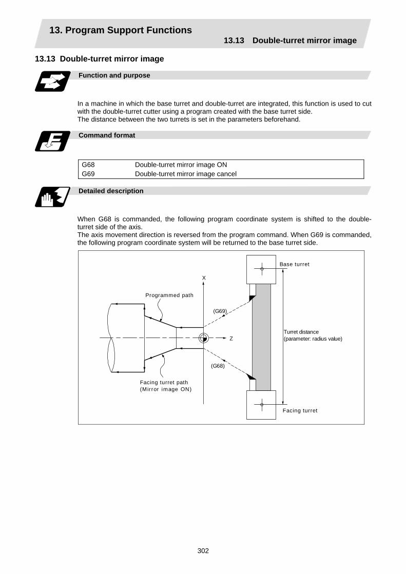
13. Program Support Functions 13.13 Double-turret mirror image
302
13.13 Double-turret mirror image
Function and purpose
In a machine in which the base turret and double-turret are integrated, this function is used to cut with the double-turret cutter using a program created with the base turret side. The distance between the two turrets is set in the parameters beforehand.
Command format
G68 Double-turret mirror image ON G69 Double-turret mirror image cancel
Detailed description
When G68 is commanded, the following program coordinate system is shifted to the double- turret side of the axis. The axis movement direction is reversed from the program command. When G69 is commanded, the following program coordinate system will be returned to the base turret side.
Programmed path
Facing turret path(Mirror image ON)
Z
X
(G69)
(G68)
Base turret
Facing turret
Turret distance(parameter: radius value)
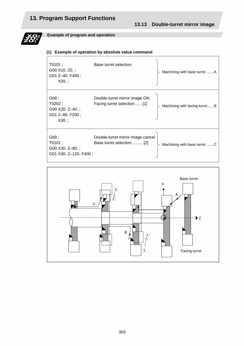
13. Program Support Functions 13.13 Double-turret mirror image
303
Example of program and operation
(1) Example of operation by absolute value command
T0101 ; G00 X10. Z0. ; G01 Z–40. F400 ;
X20. ;
Base turret selection
Machining with base turret .......A
G68 ; T0202 ; G00 X20. Z–40. ; G01 Z–80. F200 ;
X30. ;
Double-turret mirror image ON Facing turret selection……[1]
Machining with facing turret......B
G69 ; T0101 ; G00 X30. Z–80. ; G01 X30. Z–120. F400 ;
Double-turret mirror image cancelBase turret selection………[2]
Machining with base turret .......C
X
Z
Base turret
Facing turret
2.
2.’ C
B1.’
1.
A

13. Program Support Functions 13.13 Double-turret mirror image
304
(2) Example of operation by incremental value command
T0101 ; G00 X0. Z0. ; G01 Z–40. F400 ;
X20. ;
Selection of base turret
Machining with base turret .......A
G68 ; T0202 ; G00 U–10. W0. ; G01 X20. Z–80. F200 ;
X30. ;
Double-turret mirror image ON Selection of facing selection …………[1]’
Machining with facing turret......B
G69 ; T0101 ; G00 U–10. W0. ; G01 X30. Z–120. F400 ;
Double-turret mirror image cancelSelection of base turret …………[2]’
Machining with base turret .......C
X
Z
Base turret
Facing turret
2.
2.’ C
B1.’
1.
A

13. Program Support Functions 13.13 Double-turret mirror image
305
Tool compensation of turret
(1) Tool length offset
The tool length is the distance from the tool nose to the tool length base point. This also applies for the facing turret. Note that the offset amount setting value differs according to the tool length basic point position as shown below. (The settings are approached from the types in the table below.)
Tool length basic point and tool length offset
Type A Type B Type C Tool length basic point Each turret basic point Base turret basic point Workpiece face center Workpiece coordinate zero point
Workpiece face center Workpiece face center Workpiece face center
Turret interval Distance between basic points of both turrets (radius value)
0 0
Workpiece offset Workpiece coordinate zero point
– base turret tool length basic point
Workpiece coordinate zero point
– base turret tool length basic point
0
Tool length Tool length basic point – tool nose position
Tool length basic point – tool nose position
Tool length basic point – tool nose position
Outline drawing Turret basicpoint
Workpiececoordinatezero point
Base turret
Toollength
Workpieceoffset
Facing turret
Turretbasicpoint
Tool length
Turr
et in
terv
al
Turret basicpoint
Workpiececoordinatezero point
Base turret
Toollength
Workpieceoffset
Facing turretTurretbasicpoint
Toollength
Turret basicpoint
Workpiececoordinatezero point
Base turret
Facing turretTurretbasicpoint
Tool length
Tool length
The above outline drawings apply when the machine parameter (base specifications parameter) "mirr_A" is 0. If it is 1, the value is set with the tool of the facing turret in the same direction as the tool of the base turret. At this time, the tool length base point is the tool length base point of the base turret. When "mirr_A" is 1, the sign for the X-axis tool length wear amount for the facing tool is reversed and the tool nose point is set to the opposite side (for instance, 2 → 3). When tool length measurement is executed with "mirr_A" as 0, the data will be accepted with "mirr_A" as 0.
(Setting examples)
Mirr_A=0 Mirr_A=1 X Z X Z
Workpiece offset –120. –110. –120. –110. Tool length of base turret 80. 35. 80. 35. Tool wear amount of base turret –20. –5. –20. –5. Tool nose point of base turret 3 3 Tool length of facing turret 150. 40. 120. 40. Tool wear amount of facing turret –20. –5. –20. –5. Tool nose point of facing turret 2 3 Distance between turret 0 0
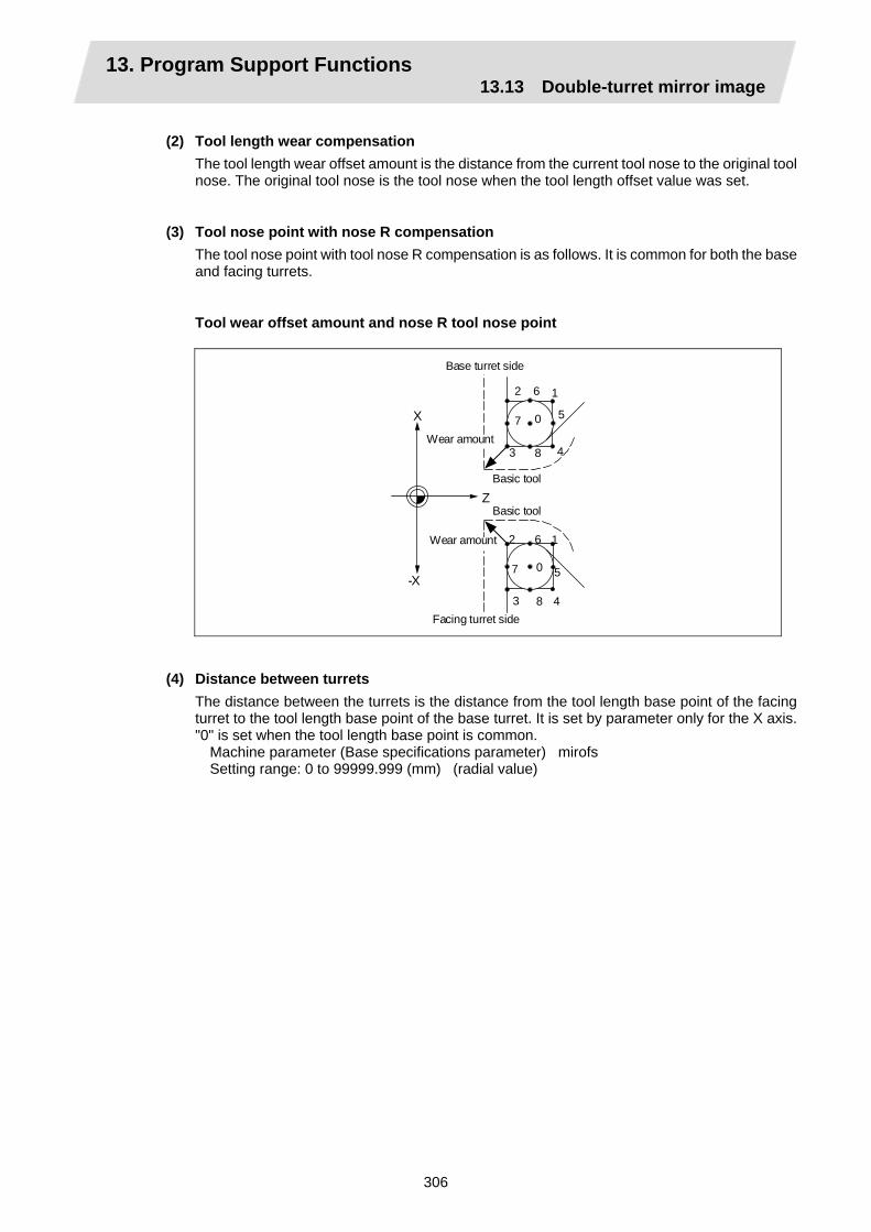
13. Program Support Functions 13.13 Double-turret mirror image
306
(2) Tool length wear compensation
The tool length wear offset amount is the distance from the current tool nose to the original tool nose. The original tool nose is the tool nose when the tool length offset value was set.
(3) Tool nose point with nose R compensation The tool nose point with tool nose R compensation is as follows. It is common for both the base and facing turrets.
Tool wear offset amount and nose R tool nose point
2 6 1
5
483
7 0
2 6 1
5
483
7 0
Z
X
-X
Base turret side
Basic tool
Facing turret side
Basic tool
Wear amount
Wear amount
(4) Distance between turrets
The distance between the turrets is the distance from the tool length base point of the facing turret to the tool length base point of the base turret. It is set by parameter only for the X axis. "0" is set when the tool length base point is common.
Machine parameter (Base specifications parameter) mirofs Setting range: 0 to 99999.999 (mm) (radial value)

13. Program Support Functions 13.14 Synchronizing operation between part systems
307
13.14 Synchronizing operation between part systems
CAUTION When programming a multi-part system, carefully observe the movements caused by other part systems' programs.
Function and purpose
The multi-axis, multi-part system complex control NC system can simultaneously run multiple machining programs independently. The synchronizing-between-part systems function is used in cases when, at some particular point during operation, the operations of part systems 1 and 2 are to be synchronized or in cases when the operation of only one part system is required.
! ......;
! ......;
! ......;
%
! ......;
! ......;
! ......;
%
Simultaneous and independent operation
← Synchronized operation Simultaneous and independent operation
← Synchronized operation Part system 2 operation only; part system 1 waiting
← Synchronized operation Simultaneous and independent operation
Part system 1 machiningprogram
No program
Part system 2 machiningprogram
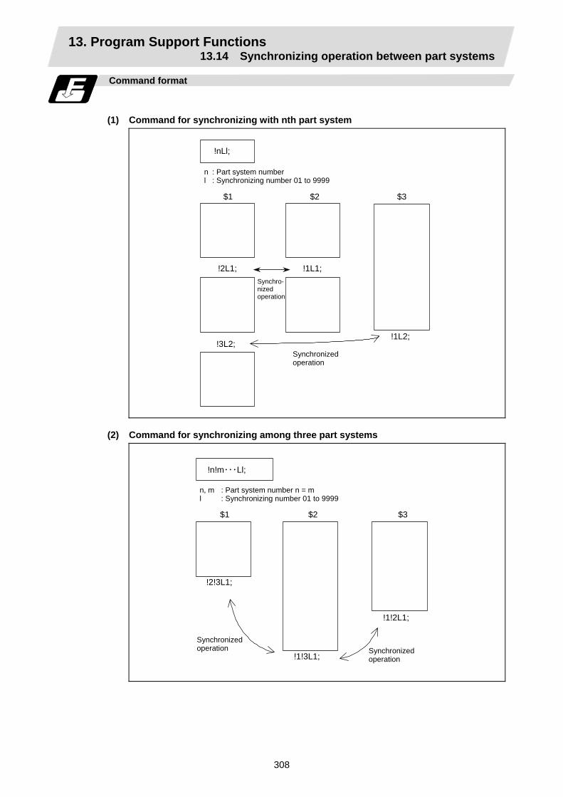
13. Program Support Functions 13.14 Synchronizing operation between part systems
308
Command format
(1) Command for synchronizing with nth part system
!nLl;
n : Part system number l : Synchronizing number 01 to 9999
$1
Synchro-nized operation
$2 $3
!2L1; !1L1;
Synchronized operation
!3L2;!1L2;
(2) Command for synchronizing among three part systems
!n!m・・・Ll;
n, m : Part system number n = m l : Synchronizing number 01 to 9999
$1 $2 $3
!2!3L1;
Synchronized operation
!1!2L1;
!1!3L1; Synchronized operation
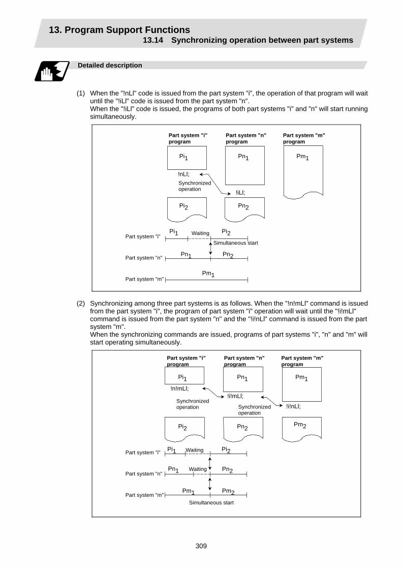
13. Program Support Functions 13.14 Synchronizing operation between part systems
309
Detailed description
(1) When the "!nLl" code is issued from the part system "i", the operation of that program will wait
until the "!iLl" code is issued from the part system "n". When the "!iLl" code is issued, the programs of both part systems "i" and "n" will start running
simultaneously.
Part system "i" program
!nLl; Synchronized operation
Pi1
Waiting
Part system "n" program
Part system "m" program
Pn1 Pm1
!iLl;
Pi2 Pn2
Part system "i"
Part system "n"
Part system "m" Pm1
Pn1 Pn2
Pi1 Pi2
Simultaneous start
(2) Synchronizing among three part systems is as follows. When the "!n!mLl" command is issued
from the part system "i", the program of part system "i" operation will wait until the "!i!mLl" command is issued from the part system "n" and the "!i!nLl" command is issued from the part system "m". When the synchronizing commands are issued, programs of part systems "i", "n" and "m" will start operating simultaneously.
Synchronized operation
Pi1
Waiting
Pn1 Pm1
Pi2 Pn2
Pm1
Pn1 Pn2
Pi1 Pi2
Simultaneous start
Pm2
!n!mLl;!i!mLl;
!i!nLl; Synchronized operation
Pm2
Waiting
Part system "i"
Part system "n"
Part system "m"
Part system "i" program
Part system "n" program
Part system "m" program
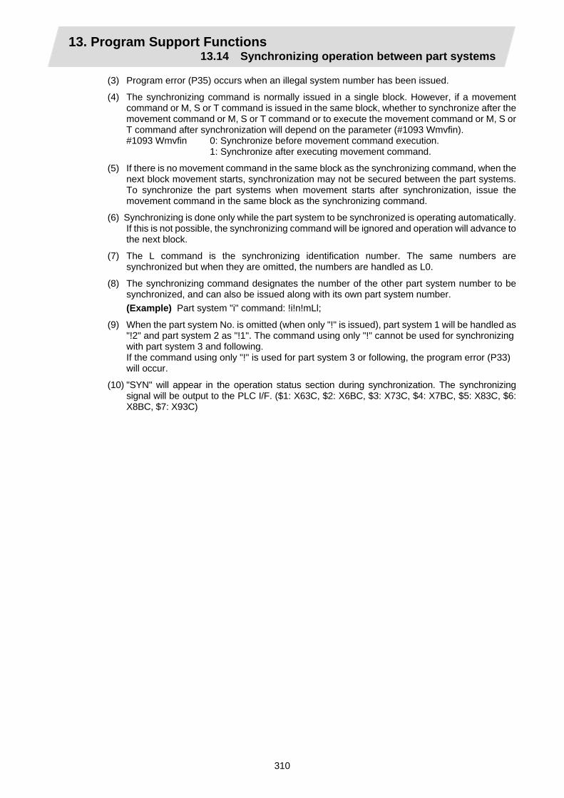
13. Program Support Functions 13.14 Synchronizing operation between part systems
310
(3) Program error (P35) occurs when an illegal system number has been issued.
(4) The synchronizing command is normally issued in a single block. However, if a movement command or M, S or T command is issued in the same block, whether to synchronize after the movement command or M, S or T command or to execute the movement command or M, S or T command after synchronization will depend on the parameter (#1093 Wmvfin).
#1093 Wmvfin 0: Synchronize before movement command execution. 1: Synchronize after executing movement command.
(5) If there is no movement command in the same block as the synchronizing command, when the next block movement starts, synchronization may not be secured between the part systems. To synchronize the part systems when movement starts after synchronization, issue the movement command in the same block as the synchronizing command.
(6) Synchronizing is done only while the part system to be synchronized is operating automatically. If this is not possible, the synchronizing command will be ignored and operation will advance to the next block.
(7) The L command is the synchronizing identification number. The same numbers are synchronized but when they are omitted, the numbers are handled as L0.
(8) The synchronizing command designates the number of the other part system number to be synchronized, and can also be issued along with its own part system number. (Example) Part system "i" command: !i!n!mLl;
(9) When the part system No. is omitted (when only "!" is issued), part system 1 will be handled as "!2" and part system 2 as "!1". The command using only "!" cannot be used for synchronizing with part system 3 and following. If the command using only "!" is used for part system 3 or following, the program error (P33) will occur.
(10) "SYN" will appear in the operation status section during synchronization. The synchronizing signal will be output to the PLC I/F. ($1: X63C, $2: X6BC, $3: X73C, $4: X7BC, $5: X83C, $6: X8BC, $7: X93C)
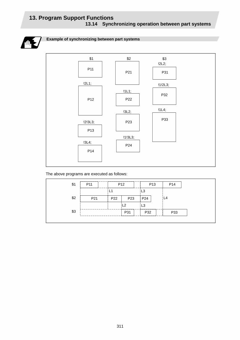
13. Program Support Functions 13.14 Synchronizing operation between part systems
311
Example of synchronizing between part systems
$1
P11
$2 $3
P21 P31
!2L2;
!2L1;
!1L1;
!1!2L3;
P12 P22 P32
!2!3L3;
!3L4;
P13
P14
!3L2;
!1!3L3;
P23
P24
P33
!1L4;
The above programs are executed as follows:
$1
$2
$3
P11 P12 P13 P14
P21 P22 P23 P24
P31 P32 P33
L1 L3
L4
L3L2

13. Program Support Functions 13.15 Start Point Designation Synchronizing (Type 1)
312
13.15 Start Point Designation Synchronizing (Type 1); G115
Function and purpose
The part system can wait for the other part system to reach the start point before starting itself.
The synchronization point can be set in the middle of a block.
Command format
!nL1 G115 X_ Z_ C_ ;
!nL1 Synchronizing command G115 G command X_ Z_ C_ Start point (Command axis and workpiece coordinate values for checking
synchronization of other part system.)
Detailed description
(1) Designate the start point using the workpiece coordinates of the other part system. (2) The start point check is executed only for the axis designated by G115.
(Example) !L2 G115 X100.;
Once the other part system reaches X100., the own part system will start. The other axes are not checked.
(3) The other part system starts first when synchronizing is executed.
(4) The own part system waits for the other part system to move and reach the designated start point, and then starts.
!
!
Other part system
Own part system
Other part system
!G115Synchronized operation
!G115
Own part system
Designated start point
Designated start point
Synchronized operation

13. Program Support Functions 13.15 Start Point Designation Synchronizing (Type 1)
313
(5) When the start point designated by G115 is not on the next block movement path of the other part system, the own system starts once the other part system has reached all of the start point axis coordinates.
例
X also has passed
X
Z
Z has passed
: Actual start point : Movement : Command point
Example:
(6) The following operation is executed by parameters (base specification parameter #1229
set01/bit5) when the start point cannot be determined by the next block movement of the other system.
(a) When the parameter is ON Operation waits until the start point is reached by the movement in the next and subsequent blocks.
Own part system
Other part system
!G115
!
Waiting
(b) When the parameter is OFF The own part system starts upon completion of the next block movement.
!G115
!
Own part system
Other part system
(7) The waiting status continues when the G115 command has been duplicated between part systems.
(8) Designate the start point using the workpiece coordinates of the other part system.
(9) Program error "P33" occurs when the G115 command is issued for 3 part systems.
(10) The single block stop function does not apply for the G115 block.
(11) When the G115 command is issued continuously in 2 or more blocks, the block in which it was issued last will be valid.
(12) A program error (P32) will occur if an address other than an axis is designated in G115 command block.

13. Program Support Functions 13.16 Start Point Designation Synchronizing (Type 2)
314
13.16 Start Point Designation Synchronizing (Type 2); G116
Function and purpose
Starting of the other part system can be delayed until the own part system reaches the designated start point. The synchronization point can be set in the middle of a block.
Command format
!nL1 G116 X_ Z_ C_ ;
!nL1 Synchronizing command G116 G command X_ Z_ C_ Start point (Command axis and workpiece coordinate values for checking
synchronization of own part system.)
Detailed description
(1) Designate the start point using the workpiece coordinates of the own part system.
(2) The start point check is executed only for the axis designated by G116.
(Example) !L1 G116 X100.;
Once the own part system reaches X100., the other part system will start. The other axes are not checked.
(3) The own part system starts first when synchronizing is performed.
(4) The other part system waits for the own part system to move and reach the designated start point, and then starts.
!G116
!
!G116
!
Own part system Other part system Own part system Other part system
Designated start point
Designated start point
Synchronized operation
Synchronized operation
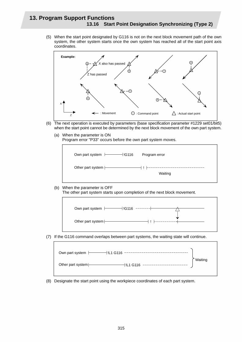
13. Program Support Functions 13.16 Start Point Designation Synchronizing (Type 2)
315
(5) When the start point designated by G116 is not on the next block movement path of the own system, the other system starts once the own system has reached all of the start point axis coordinates.
例
X also has passed
X
Z
Z has passed
Example:
: Actual start point: Movement : Command point
(6) The next operation is executed by parameters (base specification parameter #1229 set01/bit5) when the start point cannot be determined by the next block movement of the own part system.
(a) When the parameter is ON Program error "P33" occurs before the own part system moves.
Own part system
Other part system
!G116 Program error
!Waiting
(b) When the parameter is OFF The other part system starts upon completion of the next block movement.
Own part system
Other part system
!G116
!
(7) If the G116 command overlaps between part systems, the waiting state will continue.
Own part system
Other part system
!L1 G116
!L1 G116Waiting
(8) Designate the start point using the workpiece coordinates of each part system.

13. Program Support Functions 13.16 Start Point Designation Synchronizing (Type 2)
316
(9) The two other part systems start when the G116 command is issued for 3 part systems.
Own part system
Other part system A
!2!3 L1 G116
!1!3 L1
!1!2 L1Other part system B
(10) The single block stop function does not apply for the G116 block.
(11) When the G116 command is issued continuously in 2 or more blocks, the block in which it was issued last will be valid.
(12) A program error (P32) will occur if an address other than an axis is designated in G116 command block.

13. Program Support Functions 13.17 Balance cut
317
13.17 Balance cut
Function and purpose
The timing for starting the operation of the part system 1 turret and part system 2 turret can be synchronized.
Turret (part system 1)
Turret (part system 2)
Workpice
When machining a relatively thin and long workpiece with a lathe, the workpiece could slack, and highly accurate machining may not be possible. In this case, if the cutters are applied simultaneously from both sides of the workpiece and the workpiece is machined while synchronizing these (balance cut), the slack can be suppressed. Furthermore, the machining time can be shortened by machining with two cutters. With this function, the movement of two turrets belonging to different part systems can be completely synchronized, so the following type of machining can be done easily.
Command format
G15 ; G14 ; G15 G14
Balance cut command ON (modal) Balance cut command OFF (modal)

13. Program Support Functions 13.17 Balance cut
318
Detailed description
(1) Command G15 and G14 in independent blocks.
(2) G15 and G14 are modals. In the CNC's initial state, the G14 balance cut command is OFF.
(3) When the G15 command is issued, the synchronization between part systems will be maintained for all blocks until the G14 command is issued.
(4) The sections of blocks enclosed by G15 and G14 are created in the machining programs for part system 1 and part system 2. The sections enclosed by G15 and G14 are synchronized one block at a time in each part system.
<Part system 1> :
G15; N10 G01 X10. F100; N20 G01 X20.;
: :
G14 :
<Part system 2> :
G15; N10 G01 X10. F50; N20 G01 X20.;
: :
G14 :
The start timing of the $1 and $2 blocks is synchronized.
(5) If G15 or G14 is commanded in one part system, movement will not advance until the same G code is commanded in the other part system.
(6) If G15 is commanded in both part system 1 and part system 2, synchronization will be carried out one block at a time until G14 is commanded.
(7) After G14 is commanded in both part systems, part system 1 and part system 2 will operate independently.
Example of operation
<System 1>
G15; G00 X40. Z0. G01 W-30. F1000 G01 U40.W-70. G14 G01 X100.Z50. G01 Z30.
<System 2>
G15; G00 X-40. Z250. G01 W-130. F500 G01 X-80. Z50. F1000 G14 S200 G00 X-100.
…(1) …(2) …(3) …(4) …(5) …(6)
… …
… …
(1) Balance cut is turned ON with the G15 command.
(2) (3) Processing of this block will end faster for part system 1 than part system 2. The part system 1 will wait for the part system 2 process to end, and will shift the next block for both part system 1 and part system 2.
(4) The movement amount and movement speed are the same for each part system, so synchronized movement will take place.
(5) Balance cut is turned OFF with the G14 command.
(6) Each part system will operate independently after this.
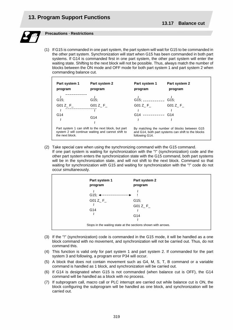
13. Program Support Functions 13.17 Balance cut
319
Precautions · Restrictions
(1) If G15 is commanded in one part system, the part system will wait for G15 to be commanded in
the other part system. Synchronization will start when G15 has been commanded in both part systems. If G14 is commanded first in one part system, the other part system will enter the waiting state. Shifting to the next block will not be possible. Thus, always match the number of blocks between the ON mode and OFF mode for both part system 1 and part system 2 when commanding balance cut.
Part system 1 program
G15; G01 Z_ F_ G14
Part system 2 program
G15; G01 Z_ F_ G14
Part system 1 can shift to the next block, but partsystem 2 will continue waiting and cannot shift tothe next block.
~~
~
~~
~
Part system 1 program
G15; G01 Z_ F_ G14
Part system 2 program
G15; G01 Z_ F_ G14
By matching the number of blocks between G15 and G14, both part systems can shift to the blocks following G14.
~~
~
~~
~
(2) Take special care when using the synchronizing command with the G15 command. If one part system is waiting for synchronization with the "!" (synchronization) code and the
other part system enters the synchronization state with the G15 command, both part systems will be in the synchronization state, and will not shift to the next block. Command so that waiting for synchronization with G15 and waiting for synchronization with the "!" code do not occur simultaneously.
Stops in the waiting state at the sections shown with arrows.
Part system 1 program
G15; G01 Z_ F_ G14
~~
~
Part system 2 program
!
G15; G01 Z_ F_ G14
~~
~
(3) If the "!" (synchronization) code is commanded in the G15 mode, it will be handled as a one
block command with no movement, and synchronization will not be carried out. Thus, do not command this.
(4) This function is valid only for part system 1 and part system 2. If commanded for the part system 3 and following, a program error P34 will occur.
(5) A block that does not contain movement such as G4, M, S, T, B command or a variable command is handled as 1 block, and synchronization will be carried out.
(6) If G14 is designated when G15 is not commanded (when balance cut is OFF), the G14 command will be handled as a block with no process.
(7) If subprogram call, macro call or PLC interrupt are carried out while balance cut is ON, the block configuring the subprogram will be handled as one block, and synchronization will be carried out.

13. Program Support Functions 13.18 2-part system simultaneous thread cutting cycle
320
13.18 2-part system simultaneous thread cutting cycle
Function and purpose
The 2-part system simultaneous thread cutting cycle function allows part system 1 and part system 2 to perform thread cutting simultaneously for the same spindle. Featured in this cycle is the command (G76.1) for simultaneously cutting threads in two places, which is known as the "2-part system simultaneous thread cutting cycle I".
13.18.1 Parameter setting command
Command format
The various parameters for thread cutting are set by commands.
G76 Pmra Q∆d Rd;
Address Meaning m Number of cutting passes for finishing (model) : 00 to 99 (times) r Chamfering amount (model) : 00 to 99 (0.1mm/rev)
This sets the chamfering width based on the thread lead 1 across a range from 0.0l to 9.9l with a 2-digit integer with the decimal point omitted.
P
a Tool nose angle (thread angle) (model) : 00 to 99 (°) The angle from 0° to 99° is assigned in 1° units. "m", "r" and "a" are commanded in succession in address P. (Example) When "m" = 5, "r" = 1.5 and "a" = 0°, P is 051500 and the
leading and trailing "0" cannot be omitted. Q ∆dmin Minimum cut amount (modal): 0 to 99999 (µm)
This is the clamping value for guaranteeing the cut amount of a single cutting pass and it is valid only for rough cutting. Finishing is performed by the cutting allowance designated separately. When the calculated value for the cut amount of a single cutting pass is less than ∆d min, it is clamped by"∆d min".
R d Finishing allowance (model) : 0 to 9999 (µm)
Detailed description
(1) The data is set in setup parameters for each part system.
(2) Issue the command for each part system.

13. Program Support Functions 13.18 2-part system simultaneous thread cutting cycle
321
13.18.2 2-part system simultaneous thread cutting cycle I ; G76.1
Command format
G76.1 X/U Z/W Ri Pk Q∆d Fl;
X/U X-axis end point coordinates of thread section ... The X-axis coordinates of the end point at the thread section are
commanded with absolute or incremental values. Z/W Z-axis end point coordinates of thread section ... The Z-axis coordinates of the end point at the thread section are
commanded with absolute or incremental values. i Taper height component (radial value) at thread section ... A straight thread is created when i = 0. k Thread height ... The thread height is commanded with a positive radial value. ∆d Cut amount ... The cut amount for the first cutting pass is commanded with a
positive radial value. l Thread lead
Detailed description
(1) When G76.1 is issued by part system 1 and part system 2, synchronized operation is done
until the command is issued to another part system. The thread-cutting cycle starts when the commands are aligned properly.
$1 $2
G00X_ Z_ ;
G76.1… ; G00X_ Z_ ;
G76… ;
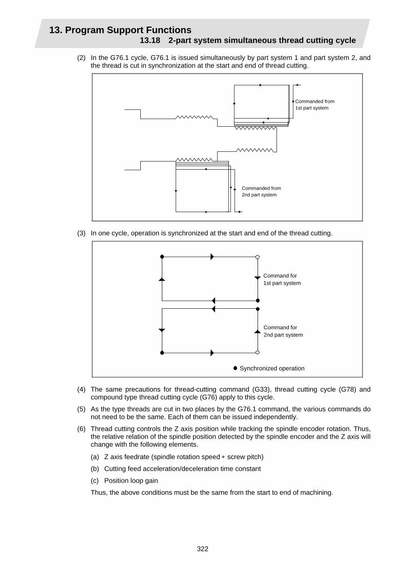
13. Program Support Functions 13.18 2-part system simultaneous thread cutting cycle
322
(2) In the G76.1 cycle, G76.1 is issued simultaneously by part system 1 and part system 2, and the thread is cut in synchronization at the start and end of thread cutting.
Commanded from 1st part system
Commanded from 2nd part system
(3) In one cycle, operation is synchronized at the start and end of the thread cutting.
Synchronized operation
Command for 1st part system
Command for 2nd part system
(4) The same precautions for thread-cutting command (G33), thread cutting cycle (G78) and
compound type thread cutting cycle (G76) apply to this cycle.
(5) As the type threads are cut in two places by the G76.1 command, the various commands do not need to be the same. Each of them can be issued independently.
(6) Thread cutting controls the Z axis position while tracking the spindle encoder rotation. Thus, the relative relation of the spindle position detected by the spindle encoder and the Z axis will change with the following elements.
(a) Z axis feedrate (spindle rotation speed ∗ screw pitch)
(b) Cutting feed acceleration/deceleration time constant
(c) Position loop gain
Thus, the above conditions must be the same from the start to end of machining.

13. Program Support Functions 13.18 2-part system simultaneous thread cutting cycle
323
13.18.3 2-part system simultaneous thread cutting cycle II ; G76.2
Command format
G76.2 X/U_ Z/W_ Rj Pk Q∆d Aa F1;
(1) Thread cutting start shift angle
a°
The meanings of the addresses other than A are the same as the 2-part system simultaneous thread cutting cycle I.
Detailed description
(1) When G76.2 is issued by part system 1 and part system 2, synchronized operation is done
until the command is issued to another system. The thread cutting cycle starts when the commands are aligned properly.
$1 $2
G00X_Z_; G76.2…;
G00X_Z_; G76.2…;
The thread cutting command starts movement after waiting for the spindle encoder's one rotation synchronization signal. However, the start point can be delayed by the a° amount. a°: Thread cutting start angle

13. Program Support Functions 13.18 2-part system simultaneous thread cutting cycle
324
(2) G76.2 assumes the same thread cutting, and deeply cuts in with the cutting amount using part system 1 and part system 2 alternately.
K
a°
Finishing allowance d
(1).......Cutting with part system 1
(2).......Cutting with part system 2
(1) (1) (1) (1) (1) (2) (2) (2) (2)(2)
d
d × n
d × 2
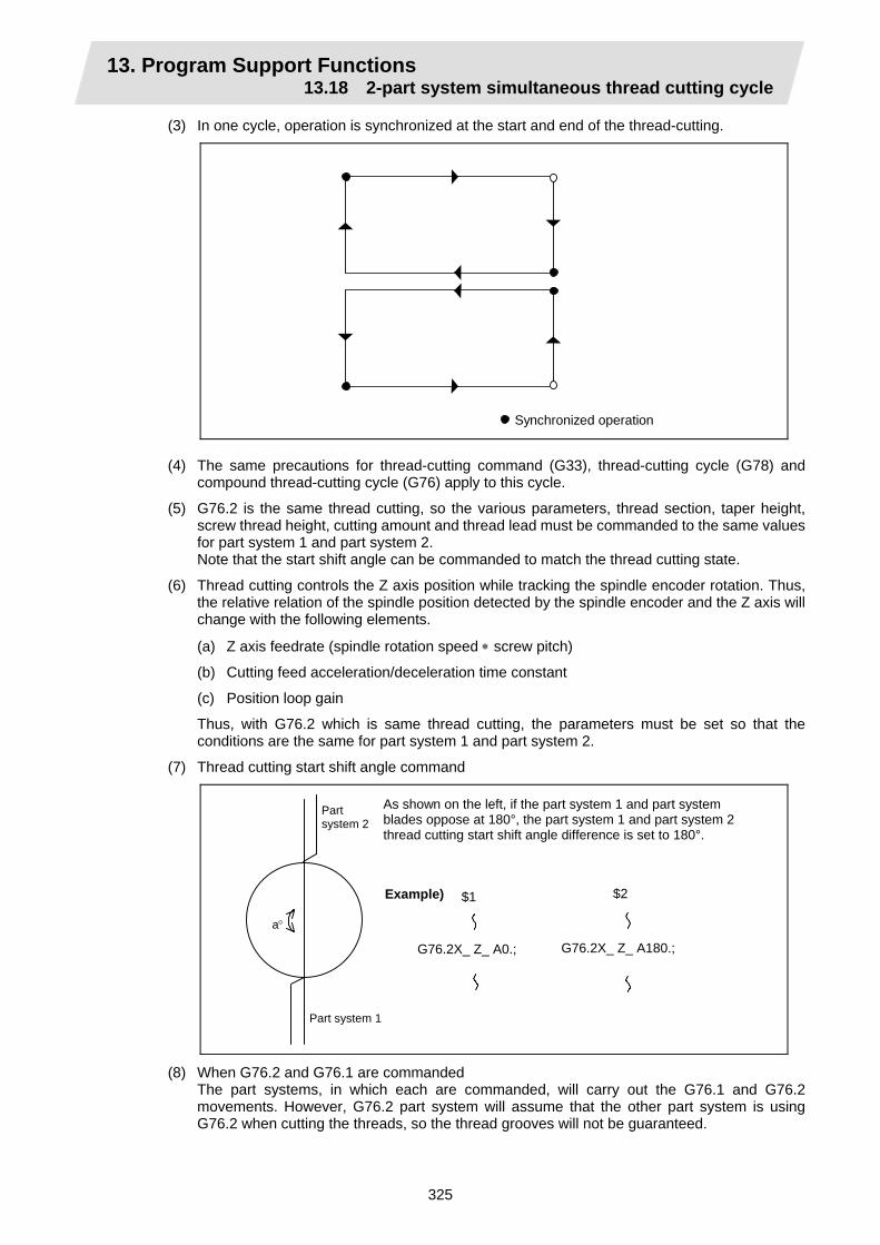
13. Program Support Functions 13.18 2-part system simultaneous thread cutting cycle
325
(3) In one cycle, operation is synchronized at the start and end of the thread-cutting.
Synchronized operation (4) The same precautions for thread-cutting command (G33), thread-cutting cycle (G78) and
compound thread-cutting cycle (G76) apply to this cycle.
(5) G76.2 is the same thread cutting, so the various parameters, thread section, taper height, screw thread height, cutting amount and thread lead must be commanded to the same values for part system 1 and part system 2.
Note that the start shift angle can be commanded to match the thread cutting state.
(6) Thread cutting controls the Z axis position while tracking the spindle encoder rotation. Thus, the relative relation of the spindle position detected by the spindle encoder and the Z axis will change with the following elements.
(a) Z axis feedrate (spindle rotation speed ∗ screw pitch)
(b) Cutting feed acceleration/deceleration time constant
(c) Position loop gain
Thus, with G76.2 which is same thread cutting, the parameters must be set so that the conditions are the same for part system 1 and part system 2.
(7) Thread cutting start shift angle command
a°
Part system 2
Part system 1
As shown on the left, if the part system 1 and part system blades oppose at 180°, the part system 1 and part system 2 thread cutting start shift angle difference is set to 180°.
Example) $1 $2
G76.2X_ Z_ A0.; G76.2X_ Z_ A180.;
(8) When G76.2 and G76.1 are commanded The part systems, in which each are commanded, will carry out the G76.1 and G76.2
movements. However, G76.2 part system will assume that the other part system is using G76.2 when cutting the threads, so the thread grooves will not be guaranteed.
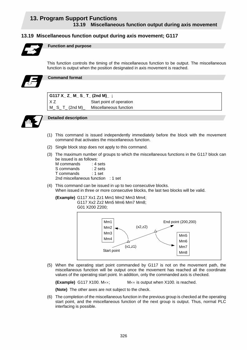
13. Program Support Functions 13.19 Miscellaneous function output during axis movement
326
13.19 Miscellaneous function output during axis movement; G117
Function and purpose
This function controls the timing of the miscellaneous function to be output. The miscellaneous function is output when the position designated in axis movement is reached.
Command format
G117 X_ Z_ M_ S_ T_ (2nd M)_ ; X Z M_ S_ T_ (2nd M)_
Start point of operation Miscellaneous function
Detailed description
(1) This command is issued independently immediately before the block with the movement
command that activates the miscellaneous function.
(2) Single block stop does not apply to this command.
(3) The maximum number of groups to which the miscellaneous functions in the G117 block can be issued is as follows: M commands : 4 sets S commands : 2 sets T commands : 1 set 2nd miscellaneous function : 1 set
(4) This command can be issued in up to two consecutive blocks. When issued in three or more consecutive blocks, the last two blocks will be valid.
(Example) G117 Xx1 Zz1 Mm1 Mm2 Mm3 Mm4; G117 Xx2 Zz2 Mm5 Mm6 Mm7 Mm8; G01 X200 Z200;
Mm1Mm2Mm3Mm4
Mm5
Mm6 Mm7 Mm8
(x1,z1)
(x2,z2)
Start point
End point (200,200)
(5) When the operating start point commanded by G117 is not on the movement path, the miscellaneous function will be output once the movement has reached all the coordinate values of the operating start point. In addition, only the commanded axis is checked.
(Example) G117 X100. M××; M×× is output when X100. is reached.
(Note) The other axes are not subject to the check.
(6) The completion of the miscellaneous function in the previous group is checked at the operating start point, and the miscellaneous function of the next group is output. Thus, normal PLC interfacing is possible.
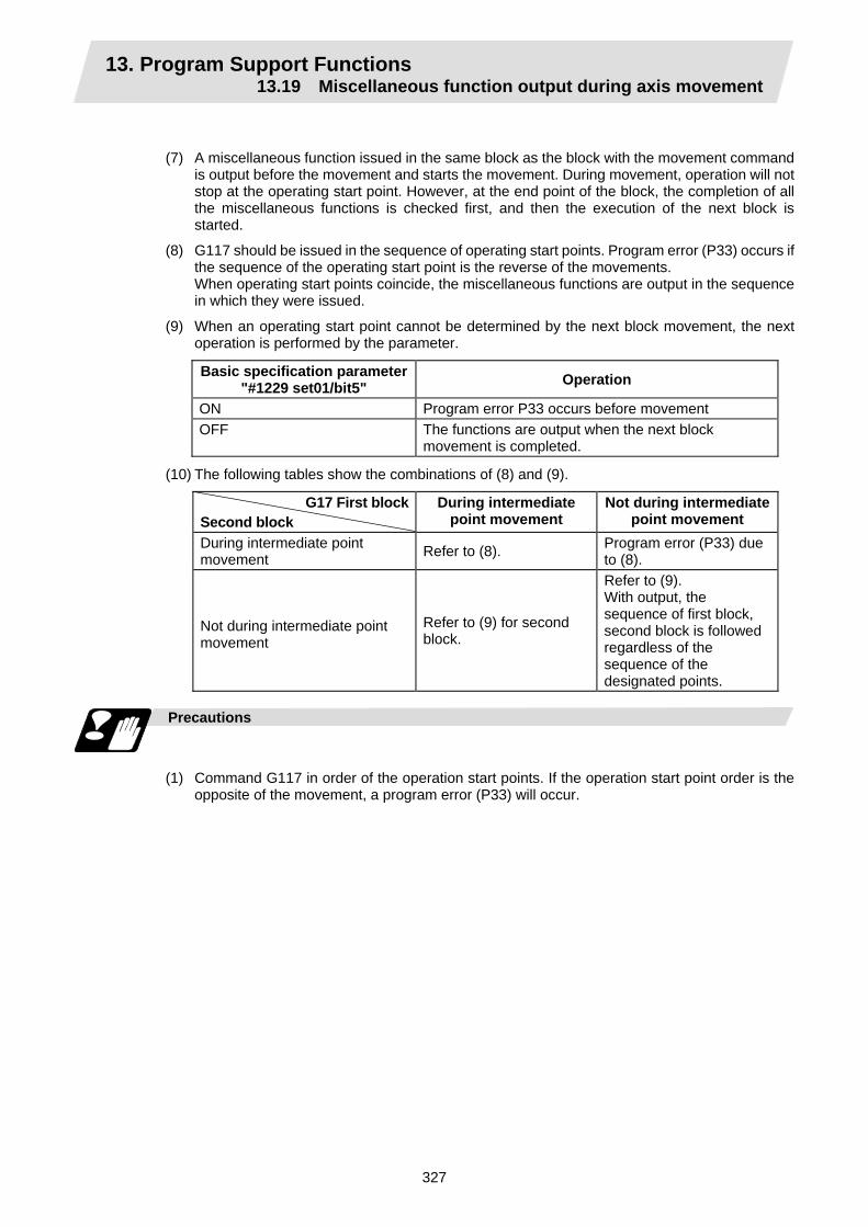
13. Program Support Functions 13.19 Miscellaneous function output during axis movement
327
(7) A miscellaneous function issued in the same block as the block with the movement command is output before the movement and starts the movement. During movement, operation will not stop at the operating start point. However, at the end point of the block, the completion of all the miscellaneous functions is checked first, and then the execution of the next block is started.
(8) G117 should be issued in the sequence of operating start points. Program error (P33) occurs if the sequence of the operating start point is the reverse of the movements. When operating start points coincide, the miscellaneous functions are output in the sequence in which they were issued.
(9) When an operating start point cannot be determined by the next block movement, the next operation is performed by the parameter.
Basic specification parameter"#1229 set01/bit5" Operation
ON Program error P33 occurs before movement OFF The functions are output when the next block
movement is completed.
(10) The following tables show the combinations of (8) and (9).
G17 First blockSecond block
During intermediate point movement
Not during intermediate point movement
During intermediate point movement Refer to (8). Program error (P33) due
to (8).
Not during intermediate point movement
Refer to (9) for second block.
Refer to (9). With output, the sequence of first block, second block is followed regardless of the sequence of the designated points.
Precautions
(1) Command G117 in order of the operation start points. If the operation start point order is the
opposite of the movement, a program error (P33) will occur.
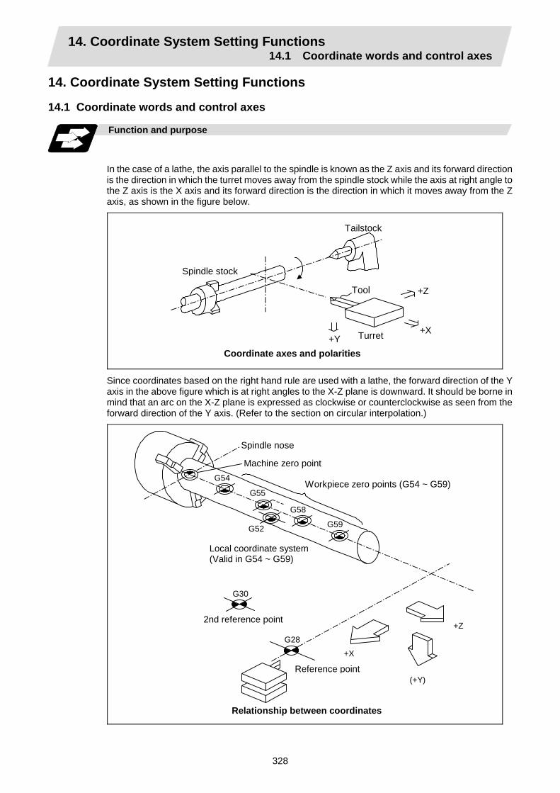
14. Coordinate System Setting Functions 14.1 Coordinate words and control axes
328
14. Coordinate System Setting Functions 14.1 Coordinate words and control axes
Function and purpose
In the case of a lathe, the axis parallel to the spindle is known as the Z axis and its forward direction is the direction in which the turret moves away from the spindle stock while the axis at right angle to the Z axis is the X axis and its forward direction is the direction in which it moves away from the Z axis, as shown in the figure below.
Spindle stock
Tailstock
Tool
Turret +X +Y
+Z
Coordinate axes and polarities
Since coordinates based on the right hand rule are used with a lathe, the forward direction of the Y axis in the above figure which is at right angles to the X-Z plane is downward. It should be borne in mind that an arc on the X-Z plane is expressed as clockwise or counterclockwise as seen from the forward direction of the Y axis. (Refer to the section on circular interpolation.)
G54
G52
G58
G55
G59
G30
G28
+X
(+Y)
+Z
Spindle nose
Machine zero point
Workpiece zero points (G54 ~ G59)
Local coordinate system(Valid in G54 ~ G59)
2nd reference point
Reference point
Relationship between coordinates

14. Coordinate System Setting Functions 14.2 Basic machine, workpiece and local coordinate systems
329
14.2 Basic machine, workpiece and local coordinate systems
Function and purpose
The basic machine coordinate system is fixed in the machine and it denotes that position which is determined inherently by the machine. The workpiece coordinate systems are used for programming and in these systems the reference point on the workpiece is set as the coordinate zero point. The local coordinate systems are created on the workpiece coordinate systems and they are designed to facilitate the programs for parts machining. Upon completion of the reference point return, the basic machine coordinate system and workpiece coordinate systems (G54 ~ G59) are automatically set with reference to the parameters. The basic machine coordinate system is set so that the first reference point is brought to the position specified by the parameter from the basic machine coordinate zero point (machine zero point).
X1
X3
+X
+Z
Z1
X2 Z2
1st reference point
Basic machinecoordinate system
Workpiececoordinatesystem 1 (G54)
Workpiececoordinatesystem 2 (G55)
Workpiececoordinatesystem 5 (G58)
Workpiece coordinate system 6 (G59)
Machine zero point
Hypothetical machine coordinate system (G92 shift)
Local coordinate system (G52)
The local coordinate systems (G52) are valid on the coordinate systems designated by workpiece coordinate systems 1 to 6. The hypothetical machine coordinate system can be set on the basic machine coordinate system using a G92 command. At this time, the workpiece coordinate system 1 to 6 is also simultaneously shifted.
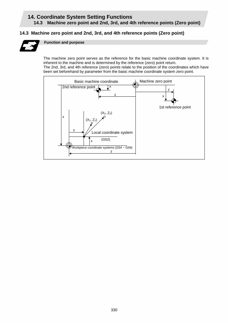
14. Coordinate System Setting Functions 14.3 Machine zero point and 2nd, 3rd, and 4th reference points (Zero point)
330
14.3 Machine zero point and 2nd, 3rd, and 4th reference points (Zero point)
Function and purpose
The machine zero point serves as the reference for the basic machine coordinate system. It is inherent to the machine and is determined by the reference (zero) point return. The 2nd, 3rd, and 4th reference (zero) points relate to the position of the coordinates which have been set beforehand by parameter from the basic machine coordinate system zero point.
(X1, Z1)
(G52)
x
z
x
z
x
z
(X2, Z2)
x
z
Machine zero point
Local coordinate system
Workpiece coordinate systems (G54 ~ G59)
Basic machine coordinate t2nd reference point
1st reference point
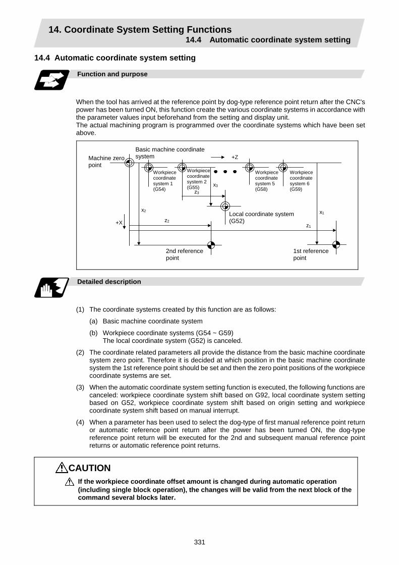
14. Coordinate System Setting Functions 14.4 Automatic coordinate system setting
331
14.4 Automatic coordinate system setting
Function and purpose
When the tool has arrived at the reference point by dog-type reference point return after the CNC's power has been turned ON, this function create the various coordinate systems in accordance with the parameter values input beforehand from the setting and display unit. The actual machining program is programmed over the coordinate systems which have been set above.
+Z
x3
+X
z3
z2
x2
z1
x1
1st reference point
Workpiececoordinatesystem 1(G54)
Local coordinate system (G52)
Basic machine coordinate system
Workpiece coordinate system 2(G55)
Workpiececoordinatesystem 5(G58)
Workpiece coordinate system 6 (G59)
2nd reference point
Machine zero point
Detailed description
(1) The coordinate systems created by this function are as follows:
(a) Basic machine coordinate system
(b) Workpiece coordinate systems (G54 ~ G59) The local coordinate system (G52) is canceled.
(2) The coordinate related parameters all provide the distance from the basic machine coordinate system zero point. Therefore it is decided at which position in the basic machine coordinate system the 1st reference point should be set and then the zero point positions of the workpiece coordinate systems are set.
(3) When the automatic coordinate system setting function is executed, the following functions are canceled: workpiece coordinate system shift based on G92, local coordinate system setting based on G52, workpiece coordinate system shift based on origin setting and workpiece coordinate system shift based on manual interrupt.
(4) When a parameter has been used to select the dog-type of first manual reference point return or automatic reference point return after the power has been turned ON, the dog-type reference point return will be executed for the 2nd and subsequent manual reference point returns or automatic reference point returns.
CAUTION If the workpiece coordinate offset amount is changed during automatic operation (including single block operation), the changes will be valid from the next block of the command several blocks later.
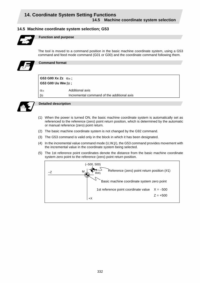
14. Coordinate System Setting Functions 14.5 Machine coordinate system selection
332
14.5 Machine coordinate system selection; G53
Function and purpose
The tool is moved to a command position in the basic machine coordinate system, using a G53 command and feed mode command (G01 or G00) and the coordinate command following them.
Command format
G53 G00 Xx Zz αα ; G53 G00 Uu Ww ββ ;
αα Additional axis ββ Incremental command of the additional axis
Detailed description
(1) When the power is turned ON, the basic machine coordinate system is automatically set as
referenced to the reference (zero) point return position, which is determined by the automatic or manual reference (zero) point return.
(2) The basic machine coordinate system is not changed by the G92 command.
(3) The G53 command is valid only in the block in which it has been designated.
(4) In the incremental value command mode (U,W,β), the G53 command provides movement with the incremental value in the coordinate system being selected.
(5) The 1st reference point coordinates denote the distance from the basic machine coordinate system zero point to the reference (zero) point return position.
(–500, 500)
+X
–Z R#1M Reference (zero) point return position (#1)
Basic machine coordinate system zero point
1st reference point coordinate value X = −500
Z = +500

14. Coordinate System Setting Functions 14.6 Coordinate system setting
333
14.6 Coordinate system setting; G92
Function and purpose
This function places the tool at the desired position, and the coordinate system is set by assigning the coordinate system setting command G92 at that position. This system can be set as desired though normally the X and Y axes are set so that the workpiece center serves as the zero point and the Z axis is set so that the workpiece end serves as the zero point.
+Z
+X
Z2
Z1
X1
X2 Z3 X3 Workpiece coordinate system 1 (G54)
Workpiece coordinate system 2 (G55)
Workpiece coordinate system 5 (G58)
Workpiece coordinate system 6 (G59)
1st reference point
Machine zero point
Local coordinate system (G52)
Hypothetical machine coordinate system (shifted by G92)
Basic machine coordinate system
Command format
G92 Xx2 Zz2 αα2 ; αα Additional axis
Detailed description
(1) The basic machine coordinate system is shifted by the G92 command, the hypothetical
machine coordinate system is created, and at the same time all workpiece coordinate systems 1 to 6 are also shifted.
(2) When G92 and S or Q are assigned, the spindle clamp rotation speed is set. (Refer to the section on setting the spindle clamp rotation speed.)
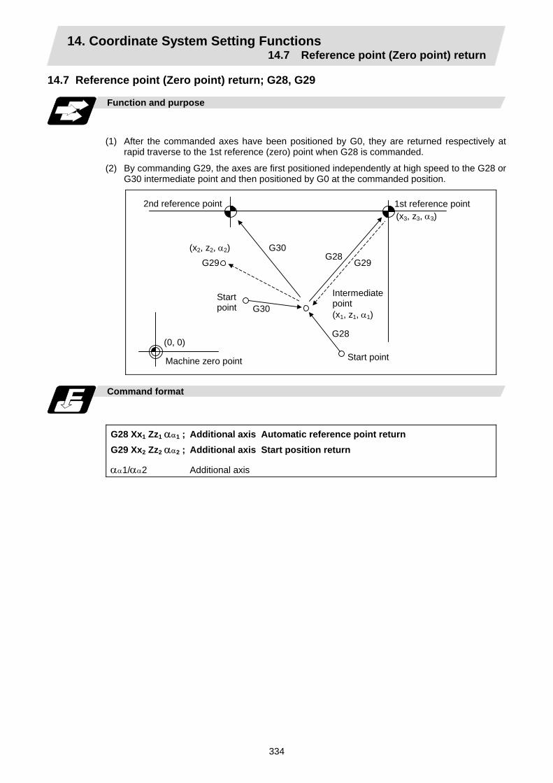
14. Coordinate System Setting Functions 14.7 Reference point (Zero point) return
334
14.7 Reference point (Zero point) return; G28, G29
Function and purpose
(1) After the commanded axes have been positioned by G0, they are returned respectively at
rapid traverse to the 1st reference (zero) point when G28 is commanded.
(2) By commanding G29, the axes are first positioned independently at high speed to the G28 or G30 intermediate point and then positioned by G0 at the commanded position.
Intermediate point (x1, z1, α1)
Machine zero point
Start point
2nd reference point
Start point
G30
(x3, z3, α3)
(x2, z2, α2)G29
G30 G28
G29
G28 (0, 0)
1st reference point
Command format
G28 Xx1 Zz1 αα1 ; Additional axis Automatic reference point return G29 Xx2 Zz2 αα2 ; Additional axis Start position return
αα1/αα2 Additional axis

14. Coordinate System Setting Functions 14.7 Reference point (Zero point) return
335
Detailed description
(1) The G28 command is equivalent to the following:
G00 Xx1 Zz1 αα1 ; G00 Xx3 Zz3 αα3 ;
In this case, x3, z3 and α3 are the reference point coordinates and they are set by parameters "#2037 G53ofs" as the distance from the basic machine coordinate system zero point.
(2) After the power has been turned ON, the axes which have not been subject to manual reference (zero) point are returned by the dog-type of return just as with the manual type. In this case, the return direction is regarded as the command sign direction. For the second and subsequent returns, the return is made at high speed to the reference (zero) point which was stored at the first time.
(3) When reference (zero) point return is completed, the zero point arrival output signal is output and also #1 appears at the axis name line on the setting and display unit screen.
(4) The G29 command is equivalent to the following:
G00 Xx1 Zz1 αα1 ; G00 Xx2 Zz2 αα2 ;
In this case, x1, z1 and α1 are the coordinate value of the G28 or G30 intermediate point.
(5) Program error (P430) results when G29 is executed when automatic reference (zero) point return (G28) is not performed after the power has been turned ON.
(6) The intermediate point coordinate value (x1, z1, α1) of the positioning point are assigned by absolute/incremental value commands.
(7) G29 is valid for either G28 or G30 but the commanded axes are positioned after a return has been made to the latest intermediate point.
(8) The tool offset will be temporarily canceled during reference point return unless it is already canceled, and the intermediate point will be the offset position.
(9) The intermediate point can also be ignored by parameter "#1091 Mpoint" setting.
(10) Control from the intermediate point to the reference (zero) point is ignored for reference (zero) point return in the machine lock status. The next block is executed when the commanded axis survives as far as the intermediate point.
(11) Mirror image is valid from the start point to the intermediate point during reference (zero) point return in the mirror image mode and the tool will move in the opposite direction to that of the command. However, mirror image is ignored from the intermediate point to the reference (zero) point and the tool will move to the reference (zero) point.
The rapid traverse (non-interpolation type) independent for each axis takes place.

14. Coordinate System Setting Functions 14.7 Reference point (Zero point) return
336
Example of program
Near-point dog
Intermediate point
1st operation after power has been turned ON
Reference (zero) point position (#1)
Rapid traverse rate
2nd and subsequent operations
Return start position
(Example 1) G28 Xx1 Zz1 ;
R
R
G0 Xx3 Zz3 ;
G0Xx1 Zz1;
1st operation after power has been turned ON
2nd and subsequent operations
Reference (zero) point position (#1)
(x1, z1)
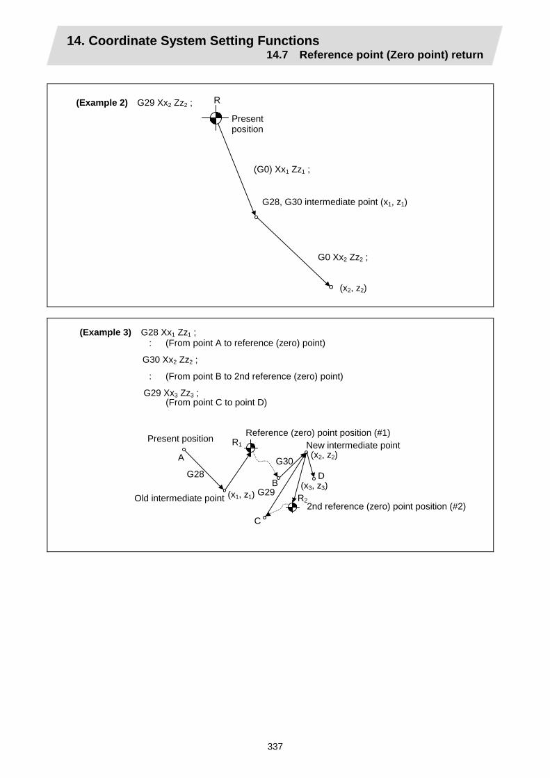
14. Coordinate System Setting Functions 14.7 Reference point (Zero point) return
337
Present position
G28, G30 intermediate point (x1, z1)
(Example 2) G29 Xx2 Zz2 ; R
(G0) Xx1 Zz1 ;
G0 Xx2 Zz2 ;
(x2, z2)
(Example 3) G28 Xx1 Zz1 ; : (From point A to reference (zero) point)
G30 Xx2 Zz2 ;
: (From point B to 2nd reference (zero) point)
G29 Xx3 Zz3 ; (From point C to point D)
(x1, z1)
C
G29B
G28
A
DG30
(x2, z2)
(x3, z3)R2
Reference (zero) point position (#1) Present position New intermediate point
Old intermediate point2nd reference (zero) point position (#2)
R1

14. Coordinate System Setting Functions 14.8 2nd, 3rd, and 4th reference point (Zero point) return
338
14.8 2nd, 3rd, and 4th reference point (Zero point) return; G30
Function and purpose
The tool can return to the 2nd, 3rd, or 4th reference (zero) point by specifying G30 P2 (P3 or P4).
Start point
Reference point
3rd reference point
Intermediate point
4th reference point
2nd reference point
G28
G29
G29
G30
G30P3G30P4
G30P
(x1, z1, α1)
G28
R#2
R#4 R#3
Command format
G30 P2 (P3, P4) Xx1 Zz1 αα1 ;
αα1 Additional axis
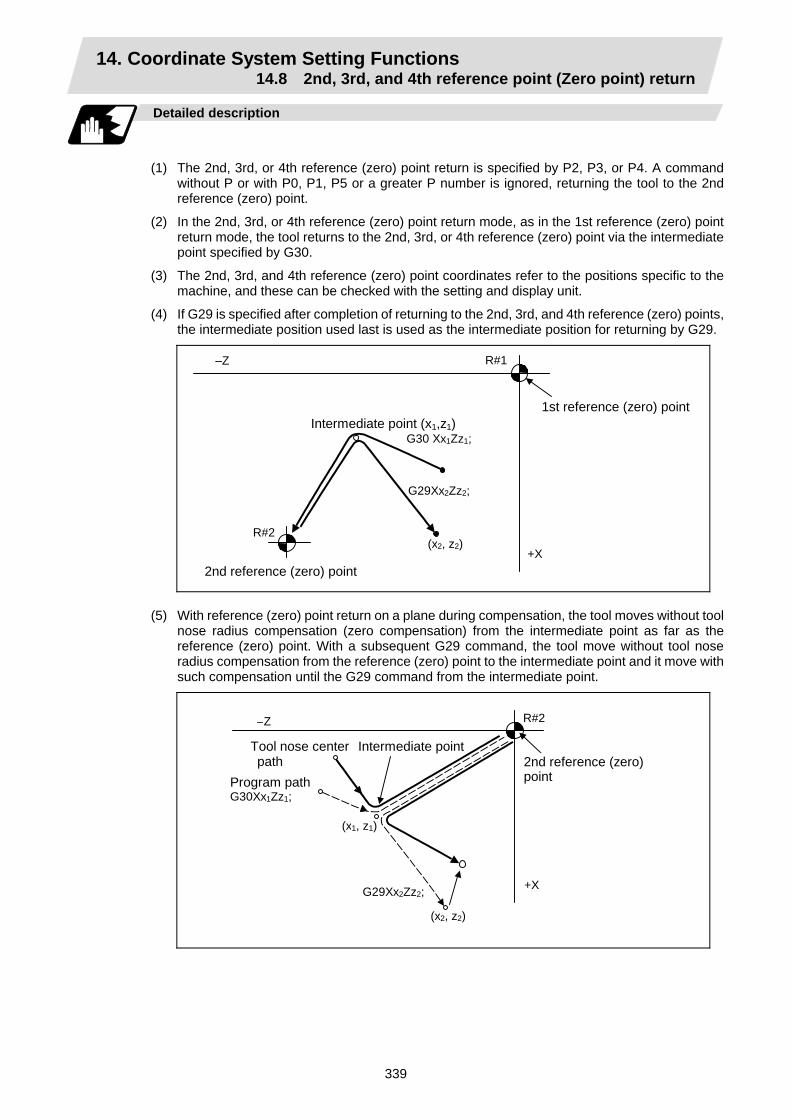
14. Coordinate System Setting Functions 14.8 2nd, 3rd, and 4th reference point (Zero point) return
339
Detailed description
(1) The 2nd, 3rd, or 4th reference (zero) point return is specified by P2, P3, or P4. A command
without P or with P0, P1, P5 or a greater P number is ignored, returning the tool to the 2nd reference (zero) point.
(2) In the 2nd, 3rd, or 4th reference (zero) point return mode, as in the 1st reference (zero) point return mode, the tool returns to the 2nd, 3rd, or 4th reference (zero) point via the intermediate point specified by G30.
(3) The 2nd, 3rd, and 4th reference (zero) point coordinates refer to the positions specific to the machine, and these can be checked with the setting and display unit.
(4) If G29 is specified after completion of returning to the 2nd, 3rd, and 4th reference (zero) points, the intermediate position used last is used as the intermediate position for returning by G29.
R#2 (x2, z2)
G29Xx2Zz2;
R#1
Intermediate point (x1,z1) G30 Xx1Zz1;
–Z
+X
1st reference (zero) point
2nd reference (zero) point (5) With reference (zero) point return on a plane during compensation, the tool moves without tool
nose radius compensation (zero compensation) from the intermediate point as far as the reference (zero) point. With a subsequent G29 command, the tool move without tool nose radius compensation from the reference (zero) point to the intermediate point and it move with such compensation until the G29 command from the intermediate point.
R#2
(x2, z2)
G29Xx2Zz2;
(x1, z1)
+X
–Z
Program path G30Xx1Zz1;
Tool nose center path
Intermediate point 2nd reference (zero) point

14. Coordinate System Setting Functions 14.8 2nd, 3rd, and 4th reference point (Zero point) return
340
(6) The tool length offset amount for the axis involved is canceled temporarily after the 2nd, 3rd, and 4th reference (zero) point return.
(7) With 2nd, 3rd, and 4th reference (zero) point return in the machine lock status, control from the intermediate point to the reference (zero) point will be ignored. When the designated axis reaches as far as the intermediate point, the next block will be executed.
(8) With 2nd, 3rd, and 4th reference (zero) point return in the mirror image mode mirror image will be valid from the start point to the intermediate point and the tool will move in the opposite direction to that of the command. However, mirror image is ignored from the intermediate point to the reference (zero) point and the tool moves to the reference (zero) point.
R#2
+X
–Z
G30P2Xx1Zz1;
2nd reference (zero) point
X-axis mirror image
No mirror image

14. Coordinate System Setting Functions 14.9 Reference point check
341
14.9 Reference point check; G27
Function and purpose
This command first positions the tool at the position assigned by the program and then, if that positioning point is the 1st reference point, it outputs the reference point arrival signal to the machine in the same way as with the G28 command. Therefore, when a machining program is prepared so that the tool will depart from the 1st reference point and return to the 1st reference point, it is possible to check whether the tool has returned to the reference point after the program has been run.
Command format
G27 Xx1 Zz1 αα1 Pp1 ;
G27 Check command Xx1 Zz1 αα1 Return control axis Pp1 Check number
P1 : 1st reference point check P2 : 2nd reference point check P3 : 3rd reference point check P4 : 4th reference point check
Detailed description
(1) If the P command has been omitted, the 1st reference point will be checked.
(2) The number of axes whose reference points can be checked simultaneously depends on the number of axes which can be controlled simultaneously.
(3) An alarm will occur if the reference point is not reached after the command is completed.

14. Coordinate System Setting Functions 14.10 Workpiece coordinate system setting and offset
342
14.10 Workpiece coordinate system setting and offset; G54 ~ G59
Function and purpose
(1) The workpiece coordinate systems are for facilitating the programming of workpiece
machining in which the reference point of the workpiece to be machined is to serve as the zero point.
(2) These commands enable the tool to move to the positions in the workpiece coordinate system. There are 6 workpiece coordinate systems which are used by the programmer for programming. (G54 ~ G59)
(3) Among the workpiece coordinate systems currently selected by these commands, any workpiece coordinate system with coordinates which have been commanded by the present position of the tool is reset. (The "present position of the tool" includes the offset amounts for nose radius, tool length and tool position offset.)
(4) An hypothetical machine coordinate system with coordinates which have been commanded by the present position of the tool is set by this command. (The "present position of the tool" includes the offset amounts for nose radius, tool length and tool position offset.) (G54 ~ G92)
Command format
(1) Workpiece coordinate system selection (G54 ~ G59)
G54 Xx1 Zz1 αα1 ;
αα1 Additional axis
(2) Workpiece coordinate system setting (G54 ~ G59) (G54) G92 Xx1 Zz1 αα1 ;
αα1 Additional axis
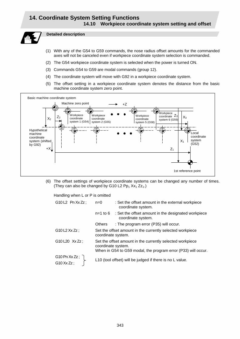
14. Coordinate System Setting Functions 14.10 Workpiece coordinate system setting and offset
343
Detailed description
(1) With any of the G54 to G59 commands, the nose radius offset amounts for the commanded
axes will not be canceled even if workpiece coordinate system selection is commanded.
(2) The G54 workpiece coordinate system is selected when the power is turned ON.
(3) Commands G54 to G59 are modal commands (group 12).
(4) The coordinate system will move with G92 in a workpiece coordinate system.
(5) The offset setting in a workpiece coordinate system denotes the distance from the basic machine coordinate system zero point.
+Z
+X
Z2
Z1
X1
X2 Z3 X3
Hypothetical machine coordinate system (shifted by G92)
Machine zero point
Local coordinate system (G52)
1st reference point
Basic machine coordinate system
Workpiece coordinate system 1 (G54)
Workpiece coordinate system 2 (G55)
Workpiece coordinate system 5 (G58)
Workpiece coordinate system 6 (G59)
(6) The offset settings of workpiece coordinate systems can be changed any number of times. (They can also be changed by G10 L2 Pp1 Xx1 Zz1.)
Handling when L or P is omitted
G10 L2 Pn Xx Zz ; n=0 : Set the offset amount in the external workpiece coordinate system.
n=1 to 6 : Set the offset amount in the designated workpiece coordinate system.
Others : The program error (P35) will occur. G10 L2 Xx Zz ; Set the offset amount in the currently selected workpiece
coordinate system. G10 L20 Xx Zz ; Set the offset amount in the currently selected workpiece
coordinate system. When in G54 to G59 modal, the program error (P33) will occur.
G10 Pn Xx Zz ; G10 Xx Zz ;
L10 (tool offset) will be judged if there is no L value.
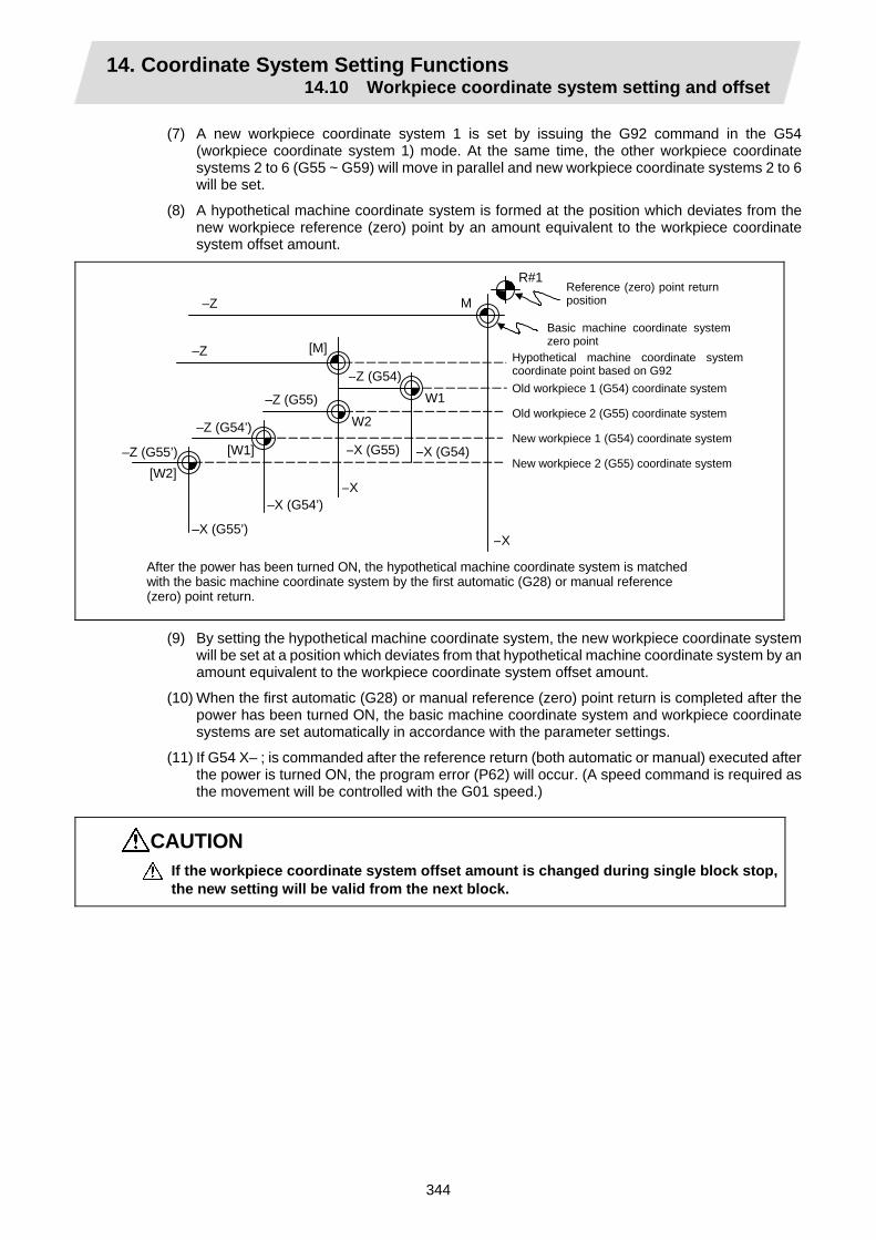
14. Coordinate System Setting Functions 14.10 Workpiece coordinate system setting and offset
344
(7) A new workpiece coordinate system 1 is set by issuing the G92 command in the G54 (workpiece coordinate system 1) mode. At the same time, the other workpiece coordinate systems 2 to 6 (G55 ~ G59) will move in parallel and new workpiece coordinate systems 2 to 6 will be set.
(8) A hypothetical machine coordinate system is formed at the position which deviates from the new workpiece reference (zero) point by an amount equivalent to the workpiece coordinate system offset amount.
R#1
–Z
–Z (G54)
–Z
–Z (G54’)
–Z (G55)
–Z (G55’) –X (G54)
–X
–X (G55)
–X
–X (G54’)
–X (G55’)
W2
W1
[W2]
[W1]
M
[M]
After the power has been turned ON, the hypothetical machine coordinate system is matched with the basic machine coordinate system by the first automatic (G28) or manual reference (zero) point return.
Hypothetical machine coordinate system coordinate point based on G92 Old workpiece 1 (G54) coordinate system
Old workpiece 2 (G55) coordinate system
New workpiece 1 (G54) coordinate system
New workpiece 2 (G55) coordinate system
Reference (zero) point returnposition
Basic machine coordinate system zero point
(9) By setting the hypothetical machine coordinate system, the new workpiece coordinate system will be set at a position which deviates from that hypothetical machine coordinate system by an amount equivalent to the workpiece coordinate system offset amount.
(10) When the first automatic (G28) or manual reference (zero) point return is completed after the power has been turned ON, the basic machine coordinate system and workpiece coordinate systems are set automatically in accordance with the parameter settings.
(11) If G54 X– ; is commanded after the reference return (both automatic or manual) executed after the power is turned ON, the program error (P62) will occur. (A speed command is required as the movement will be controlled with the G01 speed.)
CAUTION If the workpiece coordinate system offset amount is changed during single block stop, the new setting will be valid from the next block.

14. Coordinate System Setting Functions 14.10 Workpiece coordinate system setting and offset
345
Example of program
(Example 1)
R#1
(1)
M(2) (3)Z
X
(1) G28 X0 Z0 ; (2) G53 X–500 Z–1000 ; (3) G53 X0 Z0 ;
Present position
Reference (zero) pointreturn position (#1)
(Unit: mm)
When the 1st reference point coordinate is zero, the basic machine coordinate system zero point and reference (zero) point return position (#1) will coincide.
(Example 2)
(1) G28 X0 Z0 ; (2) G00 G53 X0 Z0 ; (3) G54 X−500 Z −500 ; (4) G01 W−500 F100 ; (5) U−500 ; (6) W+500 ; (7) U+500 ; (8) G00 G55 X0 Z0 ; (9) G01 Z−500 F200 ; (10) X−500 Z0 ; (11) G28 X0 Z0 ;
M –500
–1000
–1500
(G55)
(G54) –1000 –500
(G54) (G55)
W2 W1 – 500 – 1000
(11)(6)
(5) (4)
(3)
(2)
(1)
(10) (7)
(8)(9)
Present position
(Unit: mm)
Reference (zero) point return position (#1)

14. Coordinate System Setting Functions 14.10 Workpiece coordinate system setting and offset
346
(Example 3) When workpiece coordinate system G54 has deviated (−500, −500) in Example 2 (It is assumed that (3) to (10) in Example 2 have been entered in subprogram O1111.)
(1) G28 X0 Z0 ; (2) G00 G53 X0 Z0 ; (Not required when there is no basic machine
coordinate system offset.) (3) G54 X–500 Z–500 ; Amount by which workpiece coordinate system
deviates (4) G92 X0 Z0 ; New workpiece coordinate system is set. (5) M98 P1111 ;
M
–Z (G55) –Z (G54')
–X(G54)
–X(G55)
–Z (G55')
–X(G54')
–X (G55')
–X
–Z
–Z (G54)
W2
W1(4)
(3)
(2)(1)
Reference (zero) point return position (#1)
Old G54 coordinate system
New G54 coordinate system
Old G55 coordinate system
Present position
New G55 coordinate system
(Note) The workpiece coordinate system will deviate each time steps (3) to (5) are repeated. The reference point return (G28) command should therefore be issued upon completion of the program.

14. Coordinate System Setting Functions 14.11 Local coordinate system setting
347
14.11 Local coordinate system setting; G52
Function and purpose
The local coordinate systems can be set independently on the G54 ~ G59 workpiece coordinate systems using the G52 command so that the commanded position serves as the programmed zero point. The G52 command can also be used instead of the G92 command to change the deviation between the zero point in the machining program and the machining workpiece zero point.
Command format
G54 (G54 to G59) G52 Xx1 Zz1 ;
Detailed description
(1) The G52 command is valid until a new G52 command is issued and the tool does not move.
This command comes in handy for employing another coordinate system without changing the zero point positions of the workpiece coordinate systems (G54 ~ G59).
(2) The local coordinate system offset is cleared by the reference point (zero point) return or dog-type manual reference (zero) point return after the power is turned ON.
(3) The local coordinate system is canceled by (G54 ~ G59) G52 X0 Z0 ;.
(4) Coordinate commands with the absolute value cause the tool to move to the local coordinate system position.
Reference point
Incremental value
Absolute value
Workpiece coordinate system offset (DDB input, Screen setting, G10 G54 X__ Z__ ; )
External workpiece coordinate system offset (DDB input, Screen setting, G10 P0 X__ Z__ ; )
Absolute value
Machine coordinate system
Ln
Ln
Ln
R
M
G52 U_ W_ ;
Wn (n=1~6)
Local coordinate system
Workpiece coordinate system
G52 X_ Z_ ;
(Note) If the machining program is executed many times repeatedly, the workpiece coordinate system may deviate slightly per execution. Command to execute reference point return at the program end.

15. Protection Function 15.1 Chuck barrier/tailstock barrier
348
15. Protection Function 15.1 Chuck barrier/tailstock barrier; G22, G23
Function and purpose
By limiting the tool nose movement range, the chuck barrier and tailstock barrier prevent collision with the chuck and tailstock due to programming errors. If movement is commanded which exceeds the region set in the parameters, the tool will automatically stop at the barrier boundary.
X axis
Z axis
P1
P2P3
P8
P7
P4 P5
P6
P1, P2, P3 : Chuck barrier P4, P5, P6 : Tailstock barrier P7, P8 : Stored stroke limit
Command format
G22; Barriers valid G23; Barriers invalid
Set G22 and G23 commands in independent blocks.

15. Protection Function 15.1 Chuck barrier/tailstock barrier
349
Detailed description
(1) An alarm will appear if the machine stops because it was about to exceed the set region. Reset to cancel this alarm.
(2) This function is also valid during machine lock.
(3) This function is validated when all axes in which chuck barrier and tailstock barrier are set have finished their reference point returns.
(4) When there is a stored stroke check function, and the stored stroke limit region is set, the chuck barrier/tailstock barrier function is validated simultaneously with the stored stroke check function.
Setting the chuck barrier/tailstock barrier
P1P2
P3P6
P5 P4
Type 2
P1
P2 P3
P4P5
P6
Type 1
(1) Three points can be input as parameters for both the chuck barrier and tailstock barrier. Set in
the machine coordinate system. Points P1, P2 and P3 are for the chuck barrier. Points P4, P5 and P6 are for the tailstock
barrier.
(2) The barrier region should be a symmetric shape regarding the Z axis. When the X axis coordinates of barrier point P_ are a negative value, reverse the sign to the positive side, then convert and check.
The absolute value of each barrier point's X axis coordinates must be set as follows. P1 ≥ P2 ≥ P3, P4 ≥ P5 ≥ P6 (Note that the Z axis coordinates do not have to follow this setting.)
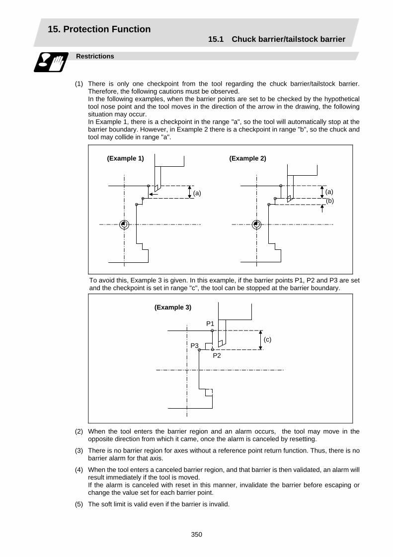
15. Protection Function 15.1 Chuck barrier/tailstock barrier
350
Restrictions
(1) There is only one checkpoint from the tool regarding the chuck barrier/tailstock barrier.
Therefore, the following cautions must be observed. In the following examples, when the barrier points are set to be checked by the hypothetical
tool nose point and the tool moves in the direction of the arrow in the drawing, the following situation may occur.
In Example 1, there is a checkpoint in the range "a", so the tool will automatically stop at the barrier boundary. However, in Example 2 there is a checkpoint in range "b", so the chuck and tool may collide in range "a".
(Example 1)
(a)
(Example 2)
(a) (b)
To avoid this, Example 3 is given. In this example, if the barrier points P1, P2 and P3 are set and the checkpoint is set in range "c", the tool can be stopped at the barrier boundary.
(Example 3)
(c)
P1
P2P3
(2) When the tool enters the barrier region and an alarm occurs, the tool may move in the opposite direction from which it came, once the alarm is canceled by resetting.
(3) There is no barrier region for axes without a reference point return function. Thus, there is no barrier alarm for that axis.
(4) When the tool enters a canceled barrier region, and that barrier is then validated, an alarm will result immediately if the tool is moved.
If the alarm is canceled with reset in this manner, invalidate the barrier before escaping or change the value set for each barrier point.
(5) The soft limit is valid even if the barrier is invalid.
16. Measurement Support Functions 16.1 Automatic tool length measurement
351
16. Measurement Support Functions 16.1 Automatic tool length measurement; G37
Function and purpose
These functions issue the command values from the measuring start position as far as the measurement time, move the tool in the direction of the measurement position, stop the machine once the tool has arrived at the sensor, cause the NC system to calculate automatically the difference between the coordinate values at that time and the coordinate values of the commanded measurement position and provide this difference as the tool offset amount. When offset is already being applied to a tool, it moves the tool toward the measurement position with the offset still applied, and if a further offset amount is generated as a result of the measurement and calculation, it provides further compensation of the present offset amount.
Command format
G37 α_ R_ D_ F_ ;
α Measuring axis address and coordinates of measurement position ......... X, Z R This commands the distance between the measurement position and
point where the movement is to start at the measuring speed (Radius value fixed, incremental value)
D This commands the range within which the tool is to stop. (Radius value fixed, incremental value)
F This commands the measuring speed. When R_, D_ or F_ is omitted, the value set in the parameter is used
instead. <Parameter> ("TLM" on machining parameter screen) • #8004 Measuring feedrate (Fp) : 0 ~ 60000 (mm/min) • #8005 Deceleration range r : 0 ~ 99999.999 (mm) • #8006 Measurement range d : 0 ~ 99999.999 (mm)

16. Measurement Support Functions 16.1 Automatic tool length measurement
352
Detailed description
(1) Operation with G37 command
D(d) D(d)F(Fp)
R(r)
(a) (b) (c) (d)
Speed Rapid traverse rate
Measurement allowable range
Distance
Operation 1
Operation 2
Operation 3
Offset amount
Normal completion Alarm stop (P607) Alarm stop (P607)
Measuring position Stop point Sensor output
Or no detection
(2) The sensor signal (measuring position arrival signal) is used in common with the skip signal.
(3) The feedrate will be 1mm/min if the F command and parameter measurement speed are 0.
(4) During the synchronous feed mode, the axis will move at the synchronous feedrate [mm/rev].
(5) An updated offset amount is valid unless it is assigned from the following T command of the G37 command.
(6) Excluding the corresponding values at the PLC side, the delay and fluctuations in the sensor signal processing range from 0 to 0.2ms. As a result, the measuring error shown below is caused.
Maximum measuring error [mm] = Measuring speed [mm/min] × 1/60 × 0.2 [ms]/1000
(7) The machine position coordinates at that point in time are ready by sensor signal detection, and the machine will overtravel and stop at a position equivalent to the servo droop.
Maximum overtravel [mm] = Measuring speed [mm/min] × 1/60 × 1/Position loop gain [1/s]
The standard position loop gain is 33 [1/s].
16. Measurement Support Functions 16.1 Automatic tool length measurement
353
Precautions
(1) Program error (P600) results if G37 is commanded when the automatic tool length
measurement function is not provided.
(2) Program error (P604) results when no axis has been commanded in the G37 block or when two or more axes have been commanded.
(3) Program error (P605) results when the T code is commanded in the G37 block. If the low-order digit or two digits is 0, the (4) error will occur.
(4) Program error (P606) results when T code is not commanded prior to the G37 block. When the low-order digit or two digits is 0, the program error (P606) will occur even if T is commanded.
(5) Program error (P607) results when the sensor signal was input outside the allowable measuring range or when the sensor signal was not detected even upon arrival at the end point. If the sensor signal stays ON during operation 3 in the above example, it will be judged as a normal measurement even when the (b) region is not present.
(6) When a manual interrupt is applied while the tool is moving at the measuring speed, a return must be made to the position prior to the interrupt and then operation must be resumed.
(7) The data commanded in G37 or the parameter setting data must meet the following conditions:
Measurement point – start point > R command or parameter r > D command or parameter d
(8) When the D command and parameter d in (7) above are zero, operation will be completed normally only when the commanded measurement point and sensor signal detection point coincide. Otherwise, program error (P607) will results.
(9) When the R and D commands as well as parameters r and d in (7) above are all zero, program error (P607) will result regardless of whether the sensor signal is present or not after the tool has been positioned at the commanded measurement point.
(10) When the measurement command distance < measurement allowable range, it becomes the measurement allowable range for all axes.
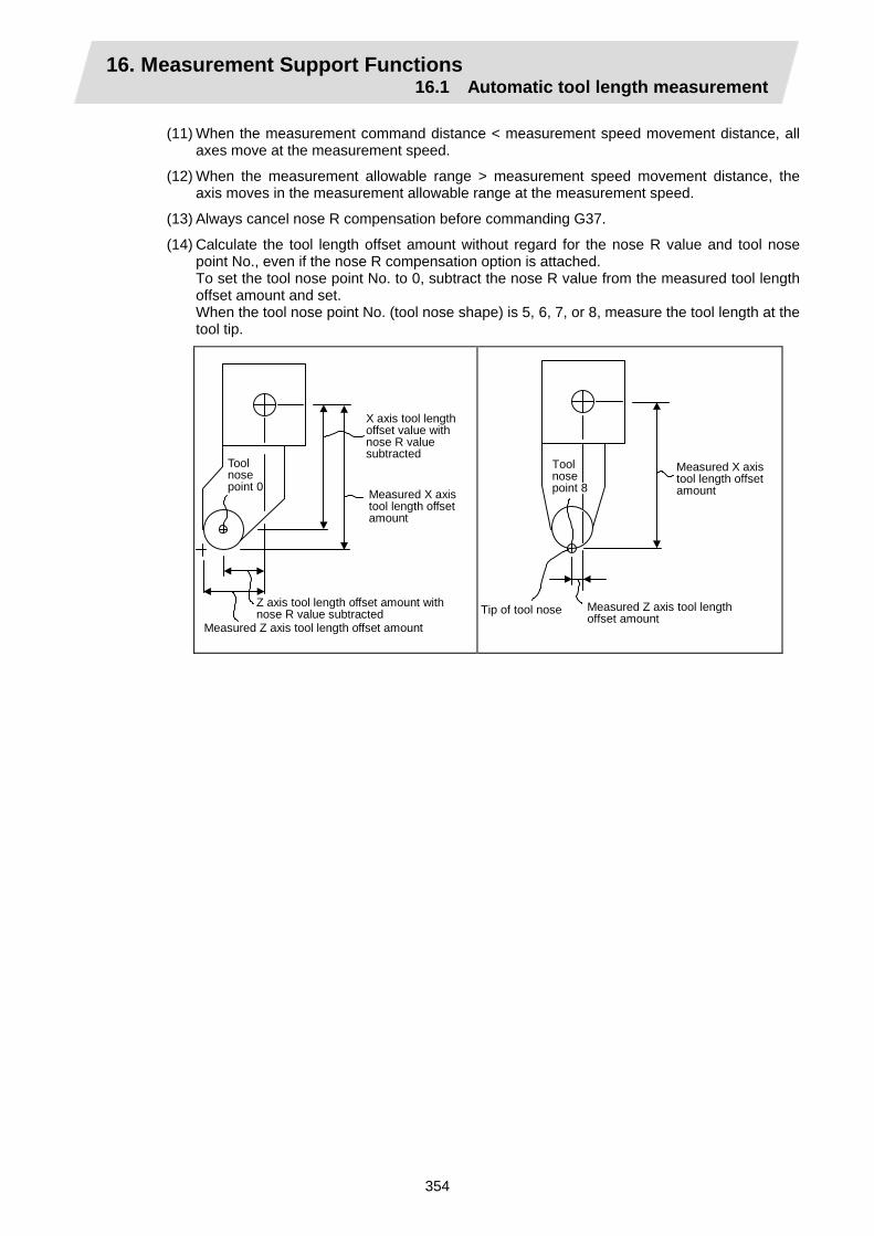
16. Measurement Support Functions 16.1 Automatic tool length measurement
354
(11) When the measurement command distance < measurement speed movement distance, all axes move at the measurement speed.
(12) When the measurement allowable range > measurement speed movement distance, the axis moves in the measurement allowable range at the measurement speed.
(13) Always cancel nose R compensation before commanding G37.
(14) Calculate the tool length offset amount without regard for the nose R value and tool nose point No., even if the nose R compensation option is attached. To set the tool nose point No. to 0, subtract the nose R value from the measured tool length offset amount and set. When the tool nose point No. (tool nose shape) is 5, 6, 7, or 8, measure the tool length at the tool tip.
X axis tool length offset value with nose R value subtracted
Tool nose point 0 Measured X axis
tool length offset amount
Z axis tool length offset amount with nose R value subtracted
Measured Z axis tool length offset amountTip of tool nose
Toolnose point 8
Measured X axis tool length offset amount
Measured Z axis tool length offset amount

16. Measurement Support Functions 16.2 Skip function
355
16.2 Skip function; G31
Function and purpose
When the skip signal is input externally during linear interpolation based on the G31 command, the machine feed is stopped immediately, the remaining distance is discarded and the command in the following block is executed.
Command format
G31 Xx/Uu Zz/Ww Ff ;
x, z, u, w Axis coordinate value; they are commanded as absolute or incremental values.
f Feedrate (mm/min)
Linear interpolation can be executed using this function. If the skip signal is input externally while this command is being executed, the machine will stop, the remaining commands will be canceled and operation will be executed from the next block.
Detailed description
(1) If Ff is commanded as the feedrate in the same block as G31 command, commanded
speed "f" will apply; if it not commanded, the value set in the parameter "#1174 skip_F" will serve as the feedrate. In either case, the F modal will not be updated.
(2) Normally, the machine will not automatically accelerate or decelerate with the G31 block. However, setting the base specification parameter "#21101 add01/bit3" to "1" allows the automatic acceleration/deceleration valid. In such case, the acceleration/deceleration will apply following to the cutting feed acceleration/deceleration pattern set with the axis specification parameter "#2003 smgst". Since the deceleration at skip signal input follows the cutting feed acceleration/deceleration pattern mentioned above, the coasting amount from the skip signal input to stop may be larger than the normal specifications (when automatic acceleration/deceleration is invalid)
(3) The stop condition (such as feed hold, stroke end) is also valid for the G31 block.
(4) With the normal specifications, override and dry run are invalid during execution of G31 block. However, setting the base specification parameter "#21101 add01/bit3" to "1" allows the override and dry run.
(5) The G31 command is unmodal and so it needs to be commanded each time.
(6) If the skip signal is input during G31 command start, the G31 command will be completed immediately. When a skip signal has not been input until the G31 block completion, the G31 command will also be completed upon completion of the movement commands.
(7) When the G31 command is issued during nose R compensation, program error (P608) will result.
(8) When there is no F command in the G31 command and the parameter speed is also zero, program error (P603) will result.
(9) If only the Z axis is commanded when the machine lock is ON or the Z axis cancel switch is ON, the skip signal will be ignored and execution will continue as far as the end of the block.

16. Measurement Support Functions 16.2 Skip function
356
Execution of G31
(Example 1) When the next block is an incremental value command
G31 Z1000 F100 ; G01 U2000 W1000 ;
X
Z
External signal entered
Movement when external signal is not entered
(Example 2) When the next block is a one axis movement command with absolute value
G31 Z1000 F100 ; G01 X1000 ;
X
Z
External signal entered Movement when external signal is not entered
(Example 3) When the next block is a two axes movement command with absolute value
G31 Z1000 F100 ; G01 X1000 Z2000 ;
X
Z
External signal entered
Movement when external signal is not entered
16. Measurement Support Functions 16.2 Skip function
357
Detailed description (Readout of skip coordinates)
As the skip signal inputting coordinate positions have been stored in the system variables #5061 (1st axis) ~ #506n (nth axis), it is possible to use them with user macro.
G00 X–100. ; G31 X–200. F60 ; Skip command #101 = #5061 Skip signal input coordinate values (workpiece
coordinate system) are readout to #101.
Detailed description (G31 coasting)
The amount of coasting from when the skip signal is input during the G31 command until the machine stops differs according to the parameter "#1174 skip_F" or F command in G31. The time to start deceleration to a stop after responding to the skip signal is short, so the machine can be stopped precisely with a small coasting amount. The coasting amount can be calculated from the following formula.
δ0 = F60 × Tp +
F60 × ( t1 ± t2 ) =
F60 × ( Tp + t1 ) ±
F60 × t2
δ0 : Coasting amount (mm) F : G31 skip speed (mm/min) Tp : Position loop time constant (s) = (position loop gain)-1 t1 : Response delay time (s) = (Time from when skip signal is detected, PC is passed, and
control unit is reached.) t2 : Response error time 0.001 (s)
When G31 is used for calculation, the value calculated from the section indicated by δ1 in the above equation can be compensated, however, δ2 results in calculation error.
Skip signal input
Stop pattern with skip signal input
Area inside shaded section denotes coasting amount δ0.
Time (S) Tp t1±t2
F
~ ~

16. Measurement Support Functions 16.2 Skip function
358
The relationship between the coasting amount and speed when Tp is 30ms and t1 is 5ms is shown in the following figure.
Coa
stin
g am
ount
δ (m
m)
Average value
Feedrate F (mm/min) Relationship between coasting amount and feedrate (example)
Max. value
Min. value
Tp=0.03t1=0.0050.050
0.040
0.030
0.020
0.010
0 10 20 30 40 50 60 70
(Note) When the base specification parameter "#21101 add01/bit3" is set to "1", the automatic acceleration/deceleration becomes valid for the deceleration at skip signal input. Thus, the coasting amount from the skip signal input to stop may be larger than when the automatic acceleration/deceleration is invalid.
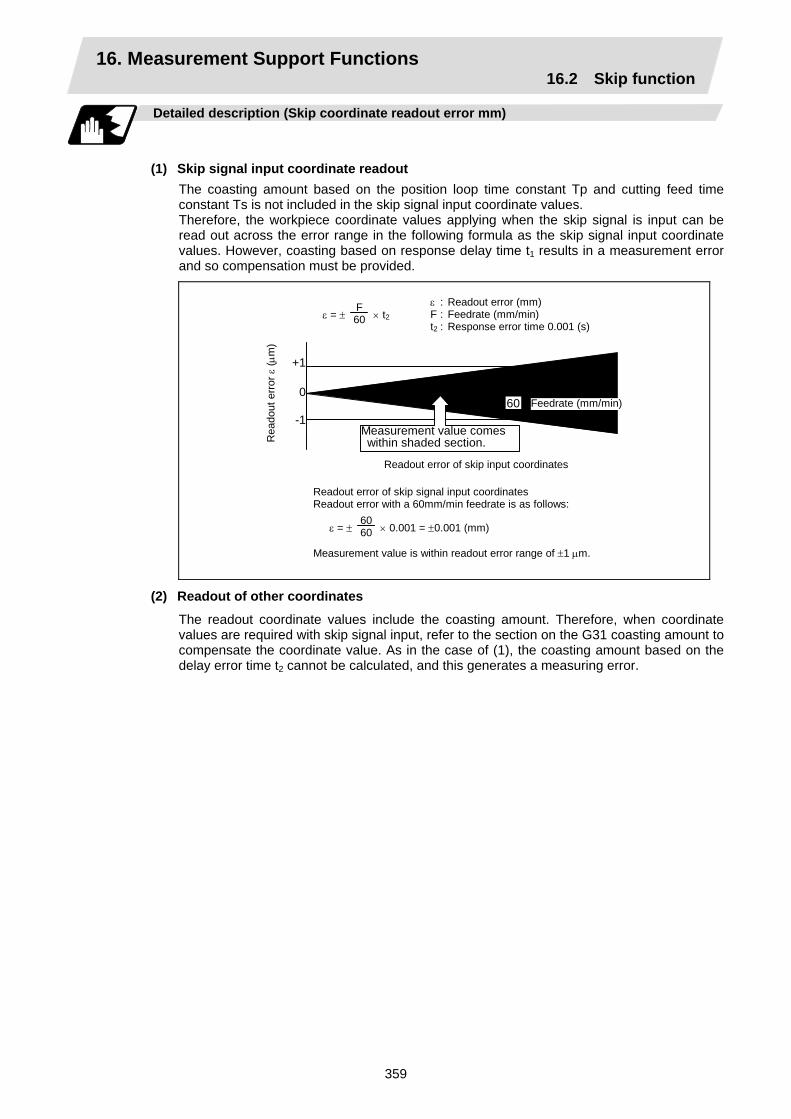
16. Measurement Support Functions 16.2 Skip function
359
Detailed description (Skip coordinate readout error mm)
(1) Skip signal input coordinate readout
The coasting amount based on the position loop time constant Tp and cutting feed time constant Ts is not included in the skip signal input coordinate values. Therefore, the workpiece coordinate values applying when the skip signal is input can be read out across the error range in the following formula as the skip signal input coordinate values. However, coasting based on response delay time t1 results in a measurement error and so compensation must be provided.
ε : Readout error (mm) F : Feedrate (mm/min) t2 : Response error time 0.001 (s)
Rea
dout
erro
r ε (µ
m)
Readout error of skip input coordinates
Readout error of skip signal input coordinates Readout error with a 60mm/min feedrate is as follows:
ε = ± 6060 × 0.001 = ±0.001 (mm)
Measurement value is within readout error range of ±1 µm.
ε = ± F60 × t2
+1
0
-1 Measurement value comes within shaded section.
60 Feedrate (mm/min)
(2) Readout of other coordinates
The readout coordinate values include the coasting amount. Therefore, when coordinate values are required with skip signal input, refer to the section on the G31 coasting amount to compensate the coordinate value. As in the case of (1), the coasting amount based on the delay error time t2 cannot be calculated, and this generates a measuring error.

16. Measurement Support Functions 16.2 Skip function
360
Examples of compensating for coasting
(1) Compensating for skip signal input coordinates
Skip signal input coordinates
Machine stop check G04 ; Skip command G31 X100. F100 ;
#111 = Response delay time t1 ;#110 = Skip feedrate ;
#105 = #101–#102 ; Coasting amount based on response delay time #102 = #110∗#111/60 ; Skip signal input coordinate readout #101 = #5061 ;
~ ~
(2) Compensating for workpiece coordinates
Coasting amount based on position loop timeconstant
Machine stop check Skip command
Coasting amount based on response delay time Skip signal input coordinate readout
Skip signal input coordinates
G04 ; G31 X100. F100 ;
#111 = Response delay time t1 ;#110 = Skip feedrate ;
#105 = #101–#102–#103 ;
#102 = #110∗#111/60 ; #101 = #5061 ;
~ ~
#112 = Position loop time constant Tp ;
#103 = #110∗#112/60 ;

16. Measurement Support Functions 16.3 Multi-stage skip function
361
16.3 Multi-stage skip function; G31.n, G04
Function and purpose
The setting of combinations of skip signals to be input enables skipping under various conditions. The actual skip operation is the same as with G31. The G commands which can specify skipping are G31.1, G31.2, G31.3, and G04, and the correspondence between the G commands and skip signals can be set by parameters.
Command format
G31.1 Xx Zz αα Ff ;
Xx Zz αα Command format axis coordinate word and target coordinates Ff Feedrate (mm/min)
Same with G31.2 and G31.3; Ff is not required with G04. As with the G31 command, this command executes linear interpolation and when the preset skip signal conditions have been met, the machine is stopped, the remaining commands are canceled, and the next block is executed.
Detailed description
(1) Feedrate G31.1 set with the parameter corresponds to "#1176 skip1f", G31.2 corresponds to
"#1178 skip2f", and G31.3 corresponds to "#1180 skip3f".
(2) A command is skipped if it meets the specified skip signal condition.
(3) The G31.n and G04 commands work the same as the G31 command for other than (1) and (2) above.
(4) The feedrates corresponding to the G31.1, G31.2, and G31.3 commands can be set by parameters.
(5) The skip conditions (logical sum of skip signals which have been set) corresponding to the G31.1, G31.2, G31.3 and G04 commands can be set by parameters.
Valid skip signal Parameter setting 4 3 2 1
1 × × × 2 × × × 3 × × 4 × × × 5 × × 6 × × 7 × 8 × × × 9 × × 10 × × 11 × 12 × × 13 × 14 × 15
(Skip when " " signal is input.)

16. Measurement Support Functions 16.3 Multi-stage skip function
362
Operation
(1) The multi-stage skip function enables the following control, thereby improving measurement
accuracy and shortening the time required for measurement.
Parameter settings : Skip condition Skip speed
G31.1 : 7 20.0mm/min (f1) G31.2 : 3 5.0mm/min (f2) G31.3 : 1 1.0mm/min (f3)
Program example
N10 G31.1 X200.0 ; N20 G31.2 X40.0 ; N30 G31.3 X1.0 ;
Operation
Skip speed
Measurement distance
N10
f
N20
N30
(f1)
(f2)
(f3)
t
Input of skip signal 3Input of skip signal 2 Input of skip signal 1
(Note 1) If skip signal 1 is input before skip signal 2 in the above operation, N20 is skipped at that point and N30 is also ignored.
(2) If a skip signal with the condition set during G04 (dwell) is input, the remaining dwell time is canceled and the following block is executed.

16. Measurement Support Functions 16.4 Multi-stage skip function 2
363
16.4 Multi-stage skip function 2 ; G31
Function and purpose
During linear interpolation, command operation is skipped if skip signal parameter Pp specified with a skip command (G31), which indicates external skip signals 1 to 4, is met. If multi-stage skip commands are issued simultaneously in different systems, both systems perform skip operation simultaneously if the input skip signals are the same, or they perform skip operation separately according to the earlier skip signal if the input skip signals are different. The skip operation is the same as with a normal skip command (G31 without P command).
X1
X2
Z
Sys
tem
1
Sys
tem
2
Skip signal 1
Skip signal 1
Same skip signals input in both systems 1 and 2
X1
X2
Sys
tem
1
Sys
tem
2 Z
Skip signal 1
Skip signal 2
Different skip signals input in systems 1 and 2
If the skip condition specified by the parameter "#1173 dwlskp" (indicating external skip signals 1 to 4) is met during execution of a dwell command (G04), the remaining dwell time is canceled and the following block is executed. Similarly, if the skip condition is met during speed dwelling, the remaining speed is canceled and the following block is executed.
Command format
G31 Xx Zz αα Pp Ff ;
Xx Zz αα Command format axis coordinate word and target coordinates Pp Skip signal command Ff Feedrate (mm/min)
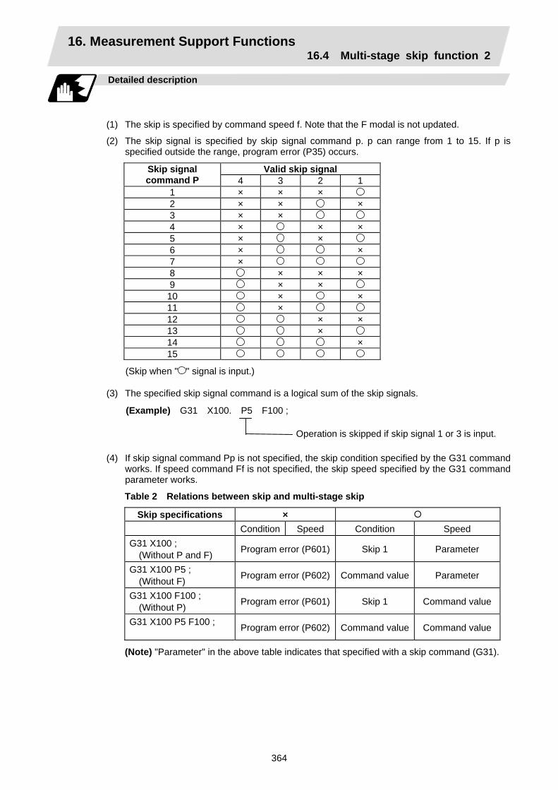
16. Measurement Support Functions 16.4 Multi-stage skip function 2
364
Detailed description
(1) The skip is specified by command speed f. Note that the F modal is not updated.
(2) The skip signal is specified by skip signal command p. p can range from 1 to 15. If p is specified outside the range, program error (P35) occurs.
Valid skip signal Skip signal command P 4 3 2 1
1 × × × 2 × × × 3 × × 4 × × × 5 × × 6 × × 7 × 8 × × × 9 × × 10 × × 11 × 12 × × 13 × 14 × 15
(Skip when " " signal is input.)
(3) The specified skip signal command is a logical sum of the skip signals.
(Example) G31 X100. P5 F100 ;
Operation is skipped if skip signal 1 or 3 is input.
(4) If skip signal command Pp is not specified, the skip condition specified by the G31 command
works. If speed command Ff is not specified, the skip speed specified by the G31 command parameter works.
Table 2 Relations between skip and multi-stage skip
Skip specifications × Condition Speed Condition Speed G31 X100 ; (Without P and F) Program error (P601) Skip 1 Parameter
G31 X100 P5 ; (Without F) Program error (P602) Command value Parameter
G31 X100 F100 ; (Without P) Program error (P601) Skip 1 Command value
G31 X100 P5 F100 ; Program error (P602) Command value Command value
(Note) "Parameter" in the above table indicates that specified with a skip command (G31).
16. Measurement Support Functions 16.4 Multi-stage skip function 2
365
(5) If skip specification is effective and P is specified as an axis address, skip signal command P is given priority and axis address P is ignored.
(Example) G31 P500. F100 ;
This is regarded as a skip signal command andprogram error (P35) results.
(6) Those items other than (1) to (5) are the same with the ordinary skip function (G31 without
P).

APPENDIXES

Appendix 1. Program Parameter Input N No. Correspondence Table
A - 1
Appendix 1. Program Parameter Input N No. Correspondence Table (Note 1) The units in the table indicate the minimum setting units for the parameter data.
(Note 2) The setting ranges given in the table are the setting ranges on the screen. Designate parameters related to the length by doubling the input setting unit. However, the parameters with " " in "etc" column (ZERO-RTN PARAM 2027, 2028, 2029) must be excluded.
(Example 1) To set 30mm in a parameter when the input setup unit is B (0.001mm) and metric system. L60000
(Example 2) To set 5 inch in a parameter when the input setup unit is B (0.0001 inch) and inch system. L100000
(Note 3) The binary type parameters must be converted into byte-type data, and commanded with a decimal data after address D.
(Example 1) Binary data 01010101B = 55H = 85D ....................... Command 85 (Example 2) ASCII code "M" = 01001101B = 4DH = 77D ............. Command 77 (B indicates Binary, H indicates Hexadecimal, and D indicates Decimal.)
P No. 2 (Axis independent parameter)
Parameter No. Details N No. Data
type Setting range (Unit) Remarks
#8201 Axis bit parameter 2 896 Bit Same as above bit0 : bit1 : bit2 : bit3 : bit4 : bit5 : bit6 : Axis
removal bit7 :
#8202 Axis bit parameter 1 897 Bit d0 : No. d bit OFF
or d1 : No. d bit ON
(d : 0 ~ 7)
bit0 : bit1 : bit2 : Soft limit
invalid bit3 : bit4 : bit5 : bit6 : bit7 :
#8204 Soft limit (−) (User stroke end lower limit)
916 2-word ± 99999999 × 2 Interpolation unit
#8205 Soft limit (+) (User stroke end upper limit)
912 2-word ± 99999999 × 2 Interpolation unit
#8206 Tool change 924 2-word ± 99999999 × 2 Interpolation unit

Appendix 1. Program Parameter Input N No. Correspondence Table
A - 2
P No. 2 (Axis independent parameter)
Parameter No. Details N No. Data
type Setting range (Unit) Remarks
#2013 OT- 292 2-word ± 99999999 × 2 Interpolation unit
Axis specifica- tions parameter
#2014 OT+ 288 2-word ± 99999999 × 2 Interpolation unit
Axis specifica- tions parameter
#2015 tlml- 300 2-word ± 99999999 × 2 Interpolation unit
Axis specifica- tions parameter
#2016 tlml+ 296 2-word ± 99999999 × 2 Interpolation unit
Axis specifica- tions parameter
#2017 tap_g 58 Word 0.25 ~ 200.00 (rad/s) Axis specifica- tions parameter
#2025 G28rap 260 2-word 1 ~ 999999 (min) Zero point return parameter
#2026 G28crp 38 Word 1 ~ 60000 (min) Zero point return parameter
#2027 G28sft 44 Word 0 ~ 65535 (μm) Zero point return parameter
#2029 grspc 42 Word -32767 ~ 999 (mm) Zero point return parameter
#2028 grmask 40 Word 0 ~ 65535 (μm) Zero point return parameter
#2030 dir(-) 20 Bit2 0 ~ 1 Zero point return parameter
#2031 noref 21 Bit2 0 ~ 1 Zero point return parameter
#2032 nochk 54 Bit0 0 ~ 1 Zero point return parameter
#2037 G53ofs 272 2-word ± 99999999 × 2 Interpolation unit
Zero point return parameter
#2038 #2_rfp 276 2-word ± 99999999 × 2 Interpolation unit
Zero point return parameter
#2039 #3_rfp 280 2-word ± 99999999 × 2 Interpolation unit
Zero point return parameter
#2040 #4_rfp 284 2-word ± 99999999 × 2 Interpolation unit
Zero point return parameter
#2061 OT-1B- 324 2-word ± 99999999 × 2 Interpolation unit
Axis specifications parameter 2
#2062 OT-1B+ 320 2-word ± 99999999 × 2 Interpolation unit
Axis specifications parameter 2

Appendix 1. Program Parameter Input N No. Correspondence Table
A - 3
P No. 5 (PLC constant)
P No. 6 (PLC timer)
P No. 7 (PLC counter)
P No. 8 (Bit selection parameter)
Parameter No. Details N No. Data
type Setting range (Unit) Remarks
#6301 ~ #6348
PLC constant 1 ~ 48
2-word 0 ~ 99999999 • N No. corresponds to the constant No. (# No.) on the PLC constant screen.
Parameter No. Details N No. Data
type Setting range (Unit) Remarks
#6000 ~ #6015
10ms addition timer (T0 ~ T15)
0 ~ 15
Word 0 ~ 32767 0.01 s
#6016 ~ #6095
10ms addition timer (T16 ~ T95)
16 ~95
Word 0 ~ 32767 0.1 s
#6096 ~ #6103
10ms addition timer (T96 ~ T103)
96 ~103
Word 0 ~ 32767 0.1 s
• Each N No. corresponds to the # No. on the PLC timer screen.
Parameter No. Details N No. Data
type Setting range (Unit) Remarks
#6200 ~ #6223
Counter (C0 ~ C23) 0 ~ 23
Word 0 ~ 32767 • N No. corresponds to the # No. on the PLC counter screen.
Parameter No. Details N No. Data
type Setting range (Unit) Remarks
#6401 ~ #6496
Bit selection parameter 0 ~ 96
Word 8-digit designation (Reading abbreviation not possible) Each bit 0 or 1 d0 : No. d bit
OFF or d1 : No. d bit ON (d : 0 ~ 7)
• N No. corresponds to the # No. on the bit selection screen.
• N Nos. 49 to 96 are used by the machine maker and Mitsubishi. These must not be used by the user.

Appendix 1. Program Parameter Input N No. Correspondence Table
A - 4
P No. 11 (Axis common parameters (per part system))
Parameter No. Details N No. Data
type Setting range (Unit) Remarks
#8004 Automatic tool length measurement instrument speed
844 2-word 1 ~ 60000 (mm/min) Machining parameter
#8005 Automatic tool length measurement deceleration range r
836 2-word 0 ~ 99999999 × 2
Interpolation unit
Machining parameter
#8006 Automatic tool length measurement deceleration range d
840 2-word 0 ~ 99999999 × 2
Interpolation unit
Machining parameter
#8008 Automatic corner override max. angle
756 2-word 0 ~ 180 Degree (°) Machining parameter
#8009 Automatic corner override precorner length
760 2-word 0 ~ 99999999 Interpolation unit
Machining parameter
#8010 Wear data input max. value
776 2-word 0 ~ 99999 Interpolation unit
Machining parameter
#8011 Wear data input max. addition
780 2-word 0 ~ 99999 Interpolation unit
Machining parameter
#8013 G83 return amount 832 2-word 0 ~ 99999999 × 2
Interpolation unit
Machining parameter
#8014 Thread cutting cycle cutoff angle
1011 Byte 0 ~ 89 Degree (°) Machining parameter
#8015 Thread cutting cycle chamfering amount
1012 Byte 1 ~ 127 0.1 lead Machining parameter
#8016 G71 cut amount 788 2-word 0 ~ 99999 × 2 Interpolation unit
Machining parameter
#8017 G71 cut amount change amount
792 2-word 0 ~ 99999 × 2 Interpolation unit
Machining parameter
#8301 X X axis chuck barrier range 1
1136 2-word ± 99999999 × 2 Interpolation unit
Barrier
#8302 X X axis chuck barrier range 2
1140 2-word ± 99999999 × 2 Interpolation unit
Barrier
#8303 X X axis chuck barrier range 3
1144 2-word ± 99999999 × 2 Interpolation unit
Barrier
#8304 X X axis chuck barrier range 4
1148 2-word ± 99999999 × 2 Interpolation unit
Barrier
#8305 X X axis chuck barrier range 5
1152 2-word ± 99999999 × 2 Interpolation unit
Barrier
#8306 X X axis chuck barrier range 6
1156 2-word ± 99999999 × 2 Interpolation unit
Barrier
#8301 Z Z axis chuck barrier range 1
1160 2-word ± 99999999 × 2 Interpolation unit
Barrier
#8302 Z Z axis chuck barrier range 2
1164 2-word ± 99999999 × 2 Interpolation unit
Barrier
#8303 Z Z axis chuck barrier range 3
1168 2-word ± 99999999 × 2 Interpolation unit
Barrier
#8304 Z Z axis chuck barrier range 4
1172 2-word ± 99999999 × 2 Interpolation unit
Barrier

Appendix 1. Program Parameter Input N No. Correspondence Table
A - 5
P No. 11 (Axis common parameters (per system))
Parameter No. Details N No. Data
type Setting range (Unit) Remarks
#8305 Z Z axis chuck barrier range 5
1176 2-word ± 99999999 × 2 Interpolation unit
Barrier
#8306 Z Z axis chuck barrier range 6
1180 2-word ± 99999999 × 2 Interpolation unit
Barrier
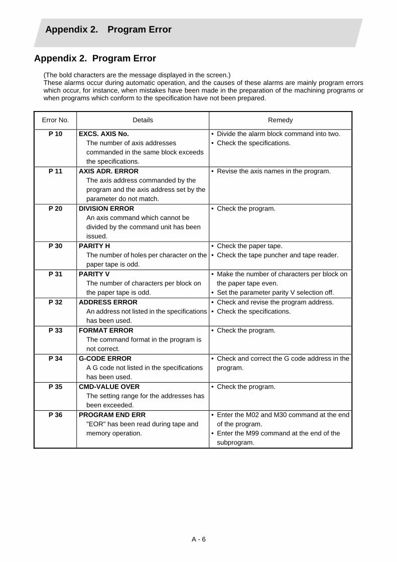
Appendix 2. Program Error
A - 6
Appendix 2. Program Error (The bold characters are the message displayed in the screen.) These alarms occur during automatic operation‚ and the causes of these alarms are mainly program errors which occur‚ for instance‚ when mistakes have been made in the preparation of the machining programs or when programs which conform to the specification have not been prepared.
Error No. Details Remedy
P 10 EXCS. AXIS No. The number of axis addresses commanded in the same block exceeds the specifications.
• Divide the alarm block command into two. • Check the specifications.
P 11 AXIS ADR. ERROR The axis address commanded by the program and the axis address set by the parameter do not match.
• Revise the axis names in the program.
P 20 DIVISION ERROR An axis command which cannot be divided by the command unit has been issued.
• Check the program.
P 30 PARITY H The number of holes per character on the paper tape is odd.
• Check the paper tape. • Check the tape puncher and tape reader.
P 31 PARITY V The number of characters per block on the paper tape is odd.
• Make the number of characters per block on the paper tape even.
• Set the parameter parity V selection off. P 32 ADDRESS ERROR
An address not listed in the specifications has been used.
• Check and revise the program address. • Check the specifications.
P 33 FORMAT ERROR The command format in the program is not correct.
• Check the program.
P 34 G-CODE ERROR A G code not listed in the specifications has been used.
• Check and correct the G code address in the program.
P 35 CMD-VALUE OVER The setting range for the addresses has been exceeded.
• Check the program.
P 36 PROGRAM END ERR "EOR" has been read during tape and memory operation.
• Enter the M02 and M30 command at the end of the program.
• Enter the M99 command at the end of the subprogram.

Appendix 2. Program Error
A - 7
Error No. Details Remedy
P 37 PROG. NO. ZERO A zero has been specified for program and sequence numbers.
• The program numbers are designated across a range from 1 to 99999999.
• The sequence numbers are designated across a range from 1 to 99999.
P 39 NO SPEC ERR A non-specified G code or address was commanded.
• Check the specifications.
P 40 PREREAD BL. ERR When cutter compensation is executed‚ there is an error in the pre-read block and so the interference check is disabled.
• Reconsider the program.
P 60 OVER CMP. LENG. The commanded movement distance is excessive. (Over 231)
• Reconsider the axis address command.
P 62 F-CMD. NOTHING No feed rate command has been issued.
• The default movement modal command at power on is G01. This causes the machine to move without a G01 command if a movement command is issued in the program, and an alarm results. Use an F command to specify the feed rate.
• Specify F with a thread lead command. P 65 NO G05P3 SPEC • Check the high-speed mode III
specifications. P 70 ARC ERROR
There is an error in the arc start and end points as well as in the arc center.
• Check the numerical values of the addresses that specify the start and end points as well as the arc center in the program.
• Check the "+" and "–" directions of the address numerical values.
P 71 ARC CENTER The arc center is not sought during R-specified circular interpolation.
• Check the numerical values of the addresses in the program.
P 72 NO HELICAL SPEC A helical command has been issued though it is not included in the specifications.
• Check the helical specifications. • An Axis 3 command was issued by the
circular interpolation command. If there is no helical specification, the linear axis is moved to the next block.
P 90 NO THREAD SPEC A thread cutting command has been issued though it is not included in the specifications.
• Check the specifications.

Appendix 2. Program Error
A - 8
Error No. Details Remedy
P 93 SCREW PITCH ERR The screw pitch has not been set correctly when the thread cutting command is issued.
• Issue the thread cutting command and then set the screw pitch command properly.
P111 PLANE CHG (CR) Plane selection commands (G17, G18, and G19) were issued when a coordinate rotation command (G68) was issued.
• Before issuing the plane selection commands, issue G68 and then G69 (coordinate rotation cancel).
P112 PLANE CHG (CC) • A plane selection command (G17‚ G18‚
G19) has been issued when the cutter compensation command (G41‚ G42) or nose R compensation command (G41‚ G42‚ G46) is issued.
• The plane selection command was issued when nose radius compensation is completed‚ there is no axial movement command after the G40 command‚ and the compensation has not been canceled.
• Issue the plane selection command after the cutter compensation command or nose radius compensation command has been canceled (issue axial movement command after the G40 cancel command).
P113 ILLEGAL PLANE The arc command axis is not on the selected plane.
• Issue arc command on the correctly selected plane.
P122 NO AUTO C-OVR An automatic corner override command (G62) has been issued though it is not included in the specifications.
• Check the specifications. • Delete the G62 command from the program.
P130 2nd AUX. ADDR The 2nd miscellaneous function address specified in the program does not match that set by the parameter.
• Check and correct the 2nd miscellaneous function address in the program.
P131 NO G96 SPEC (No constant peripheral speed) The constant peripheral speed command (G96) was issued despite the fact that such a command does not exist in the specifications.
• Check the specifications. • Change from the constant peripheral speed
command (G96) to the speed command (rpm/minute) (G97).
P132 SPINDLE S = 0 No spindle speed command has been specified.
• Reconsider the program.
P133 G96 P-No. ERR An invalid constant peripheral speed control axis has been specified.
• Reconsider the parameter specified for the constant peripheral speed control axis.

Appendix 2. Program Error
A - 9
Error No. Details Remedy
P150 NO C-CMP SPEC • Even though there were no nose radius
correction specifications, nose radius correction commands (G41, G42, and G46) were issued.
• Check the specifications.
P151 G2‚ 3 CMP. ERR A compensation command (G40‚ G41‚ G42‚ G43‚ G44‚ G46) has been issued in the arc mode (G02‚ G03).
• Issue the linear command (G01) or rapid traverse command (G00) in the compensation command block or cancel block. (Set the modal to linear interpolation.)
P152 I.S.P NOTHING In interference block processing during execution of a cutter compensation (G41 or G42) or nose radius compensation (G41‚ G42‚ or G46) command‚ the intersection point after one block is skipped cannot be determined.
• Reconsider the program.
P153 I.F ERROR An interference error has arisen while the cutter compensation command (G41‚ G42) or nose radius compensation command (G41‚ G42‚ G46) was being executed.
• Reconsider the program.
P155 F-CYC ERR (CC) A canned cycle command has been issued in the cutter compensation mode.
• The cutter compensation mode is established when a canned cycle command is executed and so the cutter compensation cancel command (G40) should be issued.
P156 BOUND DIRECT At the start of G46 nose radius compensation‚ the compensation direction is undefined if this shift vector is used.
• Change the vector to that with which the compensation direction is defined.
• Exchange with a tool having a different tip point number.
P157 SIDE REVERSED During G46 nose radius compensation‚ the compensation direction is inverted.
• Change the G command to that which allows inversion of the compensation direction (G00‚ G28‚ G30‚ G33‚ or G53).
• Exchange with a tool having a different tip point number.
• Turn on the G46 inversion error avoidance parameter.
P158 ILLEGAL TIP P. During G46 nose radius compensation‚ the tip point is illegal (other than 1 to 8).
• Change the tip point number to a legal one.

Appendix 2. Program Error
A - 10
Error No. Details Remedy
P170 NO CORR. No. The compensation number (DOO‚ TOO‚ HOO) command was not given when the cutter compensation (G41‚ G42‚ G43‚ G46) command was issued. Alternatively‚ the compensation number is larger than the number of sets in the specifications.
• Add the compensation number command to the compensation command block.
• Check the number of compensation number sets a correct it to a compensation number command within the permitted number of compensation sets.
P172 G10 L-No. ERR (G10 L-number error)
The L address command is not correct when the G10 command is issued.
• Check the address L-Number of the G10 command and correct the number.
P173 G10 P-No. ERR (G10 compensation error)
When the G10 command is issued‚ a compensation number outside the permitted number of sets in the specifications has been commanded for the compensation number command.
• First check the number of compensation sets and then set the address P designation to within the permitted number of sets.
P177 LIFE COUNT ACT Registration of tool life management data with G10 was attempted when the used data count valid signal was ON.
• The tool life management data cannot be registered when counting the used data. Turn the used data count valid signal OFF.
P178 LIFE DATA OVER The No. of registration groups‚ total No. of registered tools or the No. of registrations per group exceeded the specifications range.
• Review the No. of registrations. The maximum No. of registrations is shown below.
P179 GROUP No. ILL. • When registering the tool life
management data with G10‚ the group No. was commanded in duplicate.
• A group No. that was not registered was designated during the T 99 command.
• An M code command must be issued as a single command but coexists in the same block as that of another M code command.
• The M code commands set in the same group exist in the same block.
• The group No. cannot be commanded in duplicate. When registering the group data‚ register it in group units.
• Correct to the correct group No.
System System 1 System 2/ System 3
No. of groups 80 40/40 No. of tools 80 40/40 Per group 16
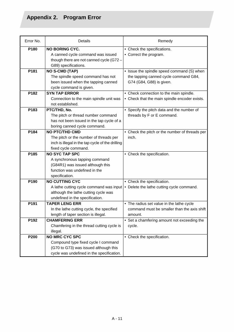
Appendix 2. Program Error
A - 11
Error No. Details Remedy
P180 NO BORING CYC. A canned cycle command was issued though there are not canned cycle (G72 – G89) specifications.
• Check the specifications. • Correct the program.
P181 NO S-CMD (TAP) The spindle speed command has not been issued when the tapping canned cycle command is given.
• Issue the spindle speed command (S) when the tapping canned cycle command G84‚ G74 (G84‚ G88) is given.
P182 SYN TAP ERROR Connection to the main spindle unit was not established.
• Check connection to the main spindle. • Check that the main spindle encoder exists.
P183 PTC/THD‚ No. The pitch or thread number command has not been issued in the tap cycle of a boring canned cycle command.
• Specify the pitch data and the number of threads by F or E command.
P184 NO PTC/THD CMD The pitch or the number of threads per inch is illegal in the tap cycle of the drilling fixed cycle command.
• Check the pitch or the number of threads per inch.
P185 NO SYC TAP SPC A synchronous tapping command (G84R1) was issued although this function was undefined in the specification.
• Check the specification.
P190 NO CUTTING CYC A lathe cutting cycle command was input although the lathe cutting cycle was undefined in the specification.
• Check the specification. • Delete the lathe cutting cycle command.
P191 TAPER LENG ERR In the lathe cutting cycle‚ the specified length of taper section is illegal.
• The radius set value in the lathe cycle command must be smaller than the axis shift amount.
P192 CHAMFERING ERR Chamfering in the thread cutting cycle is illegal.
• Set a chamfering amount not exceeding the cycle.
P200 NO MRC CYC SPC Compound type fixed cycle I command (G70 to G73) was issued although this cycle was undefined in the specification.
• Check the specification.

Appendix 2. Program Error
A - 12
Error No. Details Remedy
P201 PROG. ERR (MRC) • When called with a compound type fixed
cycle I command, the subprogram contained at least one of the following commands: • Reference point return command (G27,
G28, G30) • Thread cutting (G33) • Fixed-cycle skip-function (G31)
• The first move block of the finish shape program in compound type fixed cycle I contains an arc command.
• Delete the following G codes from this subprogram that is called with the compound type fixed cycle I commands (G70 to G73): G27‚ G28‚ G30‚ G31‚ G33‚ fixed-cycle G-code.
• Remove G2 and G3 from the first move block of the finish shape program in compound type fixed cycle I.
P202 BLOCK OVR (MRC) The number of blocks in the shape program of the compound type fixed cycle I is over 50.
• Specify 50 or a less value. The number of blocks in the shape program called by the compound type fixed cycle I commands (G70 to G73) must be decreased below 50.
P203 CONF. ERR (MRC) The compound type fixed cycle I (G70 to G73) shape program could not cut the work normally because it defined an abnormal shape.
• Check the compound type fixed cycle I (G70 to G73) shape program.
P204 VALUE ERR (MRC) A command value of the compound type fixed cycle I (G70 to G76) is illegal.
• Check the compound type fixed cycle (G70 to G76) command value.
P210 NO PAT CYC SPC A compound type fixed cycle II (G74 to G76) command was input although it was undefined in the specification.
• Check the specification.
P220 NO SPECIAL CYC No special fixed cycle specifications are available.
• Check the specifications.
P221 NO HOLE (S_CYC) A 0 has been specified for the number of holes in special fixed cycle mode.
• Reconsider the program.
P222 G36 ANGLE ERR A G36 command specifies 0 for angle intervals.
• Reconsider the program.
P223 G12 G13 R ERR The radius value specified with a G12 or G13 command is below the compensation amount.
• Reconsider the program.
P224 NO G12‚ G13 SPC There are no circular cutting specifications.
• Check the specifications.

Appendix 2. Program Error
A - 13
Error No. Details Remedy
P230 NESTING OVER • A subprogram has been called 8 or more
times in succession from the subprogram.• The program in the IC card has been
called more than once (the program in the IC card can be called only once at a time).
• Check the number of subprogram calls and correct the program so that it does not exceed 8 times.
• When using the IC card, the IC card and the number of IC card program calls.
P231 NO N-NUMBER At subprogram call time‚ the sequence number set at return from the subprogram or specified by GOTO‚ was not set.
• Specify the sequence numbers in the call block of the subprogram.
• When using the IC card, check the program in the IC card and the number of IC card program calls.
P232 NO PROGRAM No. The subprogram has not been found when the subprogram is called.
• Enter the subprogram. • Check the program number in the IC card.
P241 NO VARl NUMBER The variable number commanded is higher than the numbers in the specifications.
• Check the specifications. • Check the program variable number.
P242 EQL. SYM. MSSG. The “=” sign has not been commanded when a variable is defined.
• Designate the “=” sign in the variable definition of the program.
P243 VARIABLE ERR. An invalid variable has been specified in the left or right side of an operation expression.
• Correct the program.
P260 NO COOD-RT SPC Even though there were no coordinate rotation specifications, a coordinate rotation command was issued.
• Check the specifications.
P270 NO MACRO SPEC A macro specification was commanded though there are no such command specifications.
• Check the specifications.
P271 NO MACRO INT. A macro interrupt command has been issued though it is not included in the specifications.
• Check the specifications.
P272 MACRO ILL. A statement and a macro statement exist together in the same block.
• Reconsider the program and place the executable statement and macro statement in separate blocks.
P273 MACRO OVERCALL The frequency of the macro call has exceeded the limit imposed by the specification.
• Reconsider the program and correct it so that the macro calls do not exceed the limit imposed by the specification.

Appendix 2. Program Error
A - 14
Error No. Details Remedy
P275 MACRO ARG. EX. The number of macro call argument type II sets has exceeded the limit.
• Reconsider the program.
P276 CALL CANCEL A G67 command was issued though it was not during the G66 command modal.
• Reconsider the program. • The G67 command is the call cancel
command and so the G66 command must be designated first before it is issued.
P277 MACRO ALM MESG An alarm command has been issued in #3000.
• Refer to the operator messages on the DIAG screen.
• Refer to the instruction manual issued by the machine manufacturer.
P280 EXC. [ ‚ The number of parentheses [ ‚ ] which can be commanded in a single block has exceeded five.
• Reconsider the program and correct it so the number of "[" or "]" does not exceed five.
P281 [ ‚ ] ILLEGAL The number of "[" and "]" parentheses commanded in a single block does not match.
• Reconsider the program and correct it so that "[" and "]" parentheses are paired up properly.
P282 CALC. IMPOSS. The arithmetic formula is incorrect.
• Reconsider the program and correct the formula.
P283 DIVIDE BY ZERO The denominator of the division is zero.
• Reconsider the program and correct it so that the denominator for division in the formula is not zero.
P284 INTEGER OVER In the process of the calculation the integral number has exceeded –231 (231–1).
• Check the arithmetic formula in the program and correct it so that the value of the integral number after calculation does not exceed − 231.
P285 OVERFLOW VALUE The variable data has overflowed.
• Check the variable data in the program.
P290 IF SNT. ERROR There is an error in the IF conditional GOTO statement.
• Reconsider the program.
P291 WHILE SNT. ERR There is an error in the WHILE conditional DO -END statement.
• Reconsider the program.
P292 SETVN SNT. ERR There is an error in the SETVN statement when the variable name setting was made.
• Reconsider the program. • The number of characters in the variable
name of the SETVN statement must be 7 or less.
P293 DO-END EXCESS The number of ’s for DO-END in the WHILE conditional DO – END statement has exceed 27.
• Reconsider the program and correct it so that the number of ’s in the DO – END statement does not exceed 27.
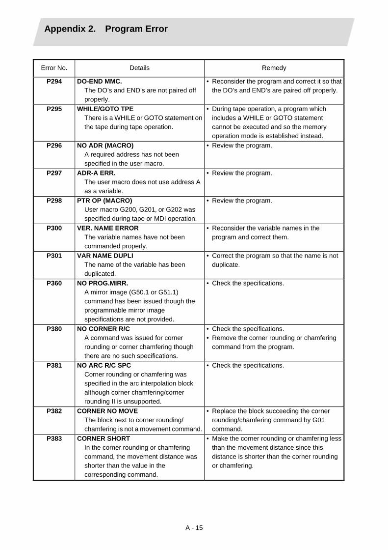
Appendix 2. Program Error
A - 15
Error No. Details Remedy
P294 DO-END MMC. The DO’s and END’s are not paired off properly.
• Reconsider the program and correct it so that the DO’s and END’s are paired off properly.
P295 WHILE/GOTO TPE There is a WHILE or GOTO statement on the tape during tape operation.
• During tape operation‚ a program which includes a WHILE or GOTO statement cannot be executed and so the memory operation mode is established instead.
P296 NO ADR (MACRO) A required address has not been specified in the user macro.
• Review the program.
P297 ADR-A ERR. The user macro does not use address A as a variable.
• Review the program.
P298 PTR OP (MACRO) User macro G200‚ G201‚ or G202 was specified during tape or MDI operation.
• Review the program.
P300 VER. NAME ERROR The variable names have not been commanded properly.
• Reconsider the variable names in the program and correct them.
P301 VAR NAME DUPLI The name of the variable has been duplicated.
• Correct the program so that the name is not duplicate.
P360 NO PROG.MIRR. A mirror image (G50.1 or G51.1) command has been issued though the programmable mirror image specifications are not provided.
• Check the specifications.
P380 NO CORNER R/C A command was issued for corner rounding or corner chamfering though there are no such specifications.
• Check the specifications. • Remove the corner rounding or chamfering
command from the program.
P381 NO ARC R/C SPC Corner rounding or chamfering was specified in the arc interpolation block although corner chamfering/corner rounding II is unsupported.
• Check the specifications.
P382 CORNER NO MOVE The block next to corner rounding/ chamfering is not a movement command.
• Replace the block succeeding the corner rounding/chamfering command by G01 command.
P383 CORNER SHORT In the corner rounding or chamfering command‚ the movement distance was shorter than the value in the corresponding command.
• Make the corner rounding or chamfering less than the movement distance since this distance is shorter than the corner rounding or chamfering.

Appendix 2. Program Error
A - 16
Error No. Details Remedy
P384 CORNER SHORT When the corner rounding or chamfering command was input‚ the movement distance in the following block was shorter than the length of the corner rounding or chamfering.
• Make the corner rounding or chamfering less than the movement distance since this distance in the following block is shorter than the corner rounding or chamfering.
P385 G0 G33 IN CONR A block with corner rounding/chamfering was given during G00 or G33 modal.
• Recheck the program.
P390 NO GEOMETRIC A geometric command was issued though there are no geometric specifications.
• Check the specifications.
P391 NO GEOMETRIC 2 There are no geometric IB specifications.
• Check the specifications.
P392 LES AGL (GEOMT) The angular difference between the geometric line and line is 1° or less.
• Correct the geometric angle.
P393 INC ERR (GEOMT) The second geometric block was specified by an incremental value.
• Specify this block by an absolute value.
P394 NO G01 (GEOMT) The second geometric block contains no linear command.
• Specify the G01 command.
P395 NO ADRS (GEOMT) The geometric format is invalid.
• Recheck the program.
P396 PL CHG. (GEOMT) A plane switching command was executed during geometric command processing.
• Execute the plane switching command before geometric command processing.
P397 ARC ERR (GEOMT) In geometric IB‚ the circular arc end point does not contact or cross the next block start point.
• Recheck the geometric circular arc command and the preceding and following commands.
P398 NO GEOMETRIC 1B Although the geometric IB specifications are not included‚ a geometric command is given.
• Check the specifications.
P420 NO PARAM IN Although the programmable parameter input specifications are not provided, the command was given.
• Check the specifications.
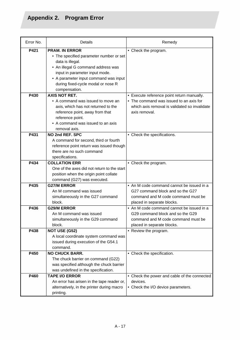
Appendix 2. Program Error
A - 17
Error No. Details Remedy
P421 PRAM. IN ERROR • The specified parameter number or set
data is illegal. • An illegal G command address was
input in parameter input mode. • A parameter input command was input
during fixed-cycle modal or nose R compensation.
• Check the program.
P430 AXIS NOT RET. • A command was issued to move an
axis‚ which has not returned to the reference point‚ away from that reference point.
• A command was issued to an axis removal axis.
• Execute reference point return manually. • The command was issued to an axis for
which axis removal is validated so invalidate axis removal.
P431 NO 2nd REF. SPC A command for second‚ third or fourth reference point return was issued though there are no such command specifications.
• Check the specifications.
P434 COLLATION ERR One of the axes did not return to the start position when the origin point collate command (G27) was executed.
• Check the program.
P435 G27/M ERROR An M command was issued simultaneously in the G27 command block.
• An M code command cannot be issued in a G27 command block and so the G27 command and M code command must be placed in separate blocks.
P436 G29/M ERROR An M command was issued simultaneously in the G29 command block.
• An M code command cannot be issued in a G29 command block and so the G29 command and M code command must be placed in separate blocks.
P438 NOT USE (G52) A local coordinate system command was issued during execution of the G54.1 command.
• Review the program.
P450 NO CHUCK BARR. The chuck barrier on command (G22) was specified although the chuck barrier was undefined in the specification.
• Check the specification.
P460 TAPE I/O ERROR An error has arisen in the tape reader or‚ alternatively‚ in the printer during macro printing.
• Check the power and cable of the connected devices.
• Check the I/O device parameters.
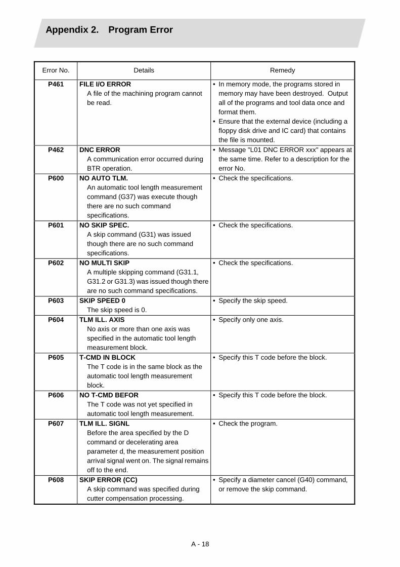
Appendix 2. Program Error
A - 18
Error No. Details Remedy
P461 FILE I/O ERROR A file of the machining program cannot be read.
• In memory mode, the programs stored in memory may have been destroyed. Output all of the programs and tool data once and format them.
• Ensure that the external device (including a floppy disk drive and IC card) that contains the file is mounted.
P462 DNC ERROR A communication error occurred during BTR operation.
• Message "L01 DNC ERROR xxx" appears at the same time. Refer to a description for the error No.
P600 NO AUTO TLM. An automatic tool length measurement command (G37) was execute though there are no such command specifications.
• Check the specifications.
P601 NO SKIP SPEC. A skip command (G31) was issued though there are no such command specifications.
• Check the specifications.
P602 NO MULTI SKIP A multiple skipping command (G31.1‚ G31.2 or G31.3) was issued though there are no such command specifications.
• Check the specifications.
P603 SKIP SPEED 0 The skip speed is 0.
• Specify the skip speed.
P604 TLM ILL. AXIS No axis or more than one axis was specified in the automatic tool length measurement block.
• Specify only one axis.
P605 T-CMD IN BLOCK The T code is in the same block as the automatic tool length measurement block.
• Specify this T code before the block.
P606 NO T-CMD BEFOR The T code was not yet specified in automatic tool length measurement.
• Specify this T code before the block.
P607 TLM ILL. SIGNL Before the area specified by the D command or decelerating area parameter d‚ the measurement position arrival signal went on. The signal remains off to the end.
• Check the program.
P608 SKIP ERROR (CC) A skip command was specified during cutter compensation processing.
• Specify a diameter cancel (G40) command‚ or remove the skip command.

Appendix 2. Program Error
A - 19
Error No. Details Remedy
P610 ILLEGAL PARA. • G114.1 was commanded when the
spindle synchronization with PLC I/F command was selected.
• Spindle synchronization was commanded to a spindle that is not connected serially.
• Check the program. • Check the argument of G114.1 command. • Check the state of spindle connection.
P701 REGARD A POINT A decimal point was added to a decimal point invalid address.
• Do not add a decimal point to the decimal point invalid address.
P990 PREPRO S/W ERR Combining commands that required pre-reading (nose R offset‚ corner chamfering/corner R‚ geometric I‚ geometric IB‚ and compound type fixed cycle commands) resulted in eight or more pre-read blocks.
• Reduce the number of commands that require pre-reading or delete such commands.

Revision history
Date of revision Manual No. Revision details
Oct. 2001 BNP-B2264B First edition created.
May. 2004 BNP-B2264D • The contents revised following to the software Ver.C and Ver.D. • Mistakes, etc. were corrected.

Notice
Every effort has been made to keep up with software and hardware revisions in the contents described in this manual. However, please understand that in some unavoidable cases simultaneous revision is not possible. Please contact your Mitsubishi Electric dealer with any questions or comments regarding the use of this product.
Duplication Prohibited This instruction manual may not be reproduced in any form, in part or in whole, without written permission from Mitsubishi Electric Corporation.
© 2001-2004 MITSUBISHI ELECTRIC CORPORATION ALL RIGHTS RESERVED

BNP-B2264D(ENG)
MITSUBISHI ELECTRIC CORPORATION HEAD OFFICE : MITSUBISHI DENKI BLDG., 2-2-3, MARUNOUCHI, CHIYODA-KU, TOKYO 100-8310, JAPAN
MC6/C64/C64T(L)
008-167
(0405) MEE
Specifications subject to change without notice.Printed in Japan on recycled paper.
MODEL
Manual No.
MODELCODE