Embed Size (px)
Citation preview
Mellanox Technologieswww.mellanox.com
Mellanox WinOF-2 User Manual
Rev 1.80
Mellanox Technologies350 Oakmead Parkway Suite 100Sunnyvale, CA 94085U.S.A.www.mellanox.comTel: (408) 970-3400Fax: (408) 970-3403
© Copyright 2017. Mellanox Technologies Ltd. All Rights Reserved.
Mellanox®, Mellanox logo, Accelio®, BridgeX®, CloudX logo, CompustorX®, Connect-IB®, ConnectX®, CoolBox®, CORE-Direct®, EZchip®, EZchip logo, EZappliance®, EZdesign® , EZdriver®, EZsystem®, GPUDirect® , InfiniHost®, InfiniBridge®, InfiniScale®, Kotura®, Kotura logo, Mellanox CloudRack®, Mellanox CloudXMellanox®, Mellanox Federal Systems®, Mellanox HostDirect®, Mellanox Multi-Host®, Mellanox Open Ethernet® , Mellanox OpenCloud®, Mellanox OpenCloud Logo® , Mellanox PeerDirect®, Mellanox ScalableHPC®, Mellanox StorageX®, Mellanox TuneX®, Mellanox Connect Accelerate Outperform logo, Mellanox Virtual Modular Switch®, MetroD X®, MetroX®, MLNX-OS®, NP-1c®, NP-2®, NP-3®, Open Ethernet logo , PhyX®, PlatformX®, PSIPHY®, SiPhy®, StoreX®, SwitchX®, Tilera®, Tilera logo, TestX®, TuneX®, The Generation of Open Ethernet logo, UFM®, Unbreakable Link®, Virtual Protocol Interconnect® , Voltaire® and Voltaire logo are registered trademarks of Mellanox Technologies, Ltd.
All other trademarks are property of their respective owners .
For the most updated list of Mellanox trademarks, visit http://www.mellanox.com/page/trademarks
NOTE:THIS HARDWARE, SOFTWARE OR TEST SUITE PRODUCT (“PRODUCT(S)”) AND ITS RELATED DOCUMENTATION ARE PROVIDED BY MELLANOX TECHNOLOGIES “AS-IS” WITH ALL FAULTS OF ANY KIND AND SOLELY FOR THE PURPOSE OF AIDING THE CUSTOMER IN TESTING APPLICATIONS THAT USE THE PRODUCTS IN DESIGNATED SOLUTIONS . THE CUSTOMER'S MANUFACTURING TEST ENVIRONMENT HAS NOT MET THE STANDARDS SET BY MELLANOX TECHNOLOGIES TO FULLY QUALIFY THE PRODUCT (S) AND/OR THE SYSTEM USING IT. THEREFORE, MELLANOX TECHNOLOGIES CANNOT AND DOES NOT GUARANTEE OR WARRANT THAT THE PRODUCTS WILL OPERATE WITH THE HIGHEST QUALITY. ANY EXPRESS OR IMPLIED WARRANTIES, INCLUDING, BUT NOT LIMITED TO, THE IMPLIED WARRANTIES OF MERCHANTABILITY, FITNESS FOR A PARTICULAR PURPOSE AND NONINFRINGEMENT ARE DISCLAIMED. IN NO EVENT SHALL MELLANOX BE LIABLE TO CUSTOMER OR ANY THIRD PARTIES FOR ANY DIRECT, INDIRECT, SPECIAL, EXEMPLARY, OR CONSEQUENTIAL DAMAGES OF ANY KIND (INCLUDING, BUT NOT LIMITED TO, PAYMENT FOR PROCUREMENT OF SUBSTITUTE GOODS OR SERVICES; LOSS OF USE, DATA, OR PROFITS; OR BUSINESS INTERRUPTION) HOWEVER CAUSED AND ON ANY THEORY OF LIABILITY, WHETHER IN CONTRACT, STRICT LIABILITY, OR TORT (INCLUDING NEGLIGENCE OR OTHERWISE ) ARISING IN ANY WAY FROM THE USE OF THE PRODUCT(S) AND RELATED DOCUMENTATION EVEN IF ADVISED OF THE POSSIBILITY OF SUCH DAMAGE.
Doc #: MLNX-15-3280 2Mellanox Technologies
Rev 1.80 3Mellanox Technologies
Table of Contents
Document Revision History . . . . . . . . . . . . . . . . . . . . . . . . . . . . . . . . . . . . . . . 10About this Manual . . . . . . . . . . . . . . . . . . . . . . . . . . . . . . . . . . . . . . . . . . . . . . . 18
Scope . . . . . . . . . . . . . . . . . . . . . . . . . . . . . . . . . . . . . . . . . . . . . . . . . . . . . . . . . . . . 18Intended Audience . . . . . . . . . . . . . . . . . . . . . . . . . . . . . . . . . . . . . . . . . . . . . . . . . 18Documentation Conventions . . . . . . . . . . . . . . . . . . . . . . . . . . . . . . . . . . . . . . . . . 18Common Abbreviations and Acronyms . . . . . . . . . . . . . . . . . . . . . . . . . . . . . . . . 19Related Documents . . . . . . . . . . . . . . . . . . . . . . . . . . . . . . . . . . . . . . . . . . . . . . . . 20
Chapter 1 Introduction . . . . . . . . . . . . . . . . . . . . . . . . . . . . . . . . . . . . . . . . . . . 22Chapter 2 WinOF-2 Driver Installation. . . . . . . . . . . . . . . . . . . . . . . . . . . . . . . 24
2.1 Downloading Mellanox WinOF-2 Driver . . . . . . . . . . . . . . . . . . . . . . . . . . . 242.2 Installing Mellanox WinOF-2 Driver . . . . . . . . . . . . . . . . . . . . . . . . . . . . . . 24
2.2.1 Attended Installation . . . . . . . . . . . . . . . . . . . . . . . . . . . . . . . . . . . . . . . . . . 252.2.2 Unattended Installation . . . . . . . . . . . . . . . . . . . . . . . . . . . . . . . . . . . . . . . . 30
2.3 Installation Results . . . . . . . . . . . . . . . . . . . . . . . . . . . . . . . . . . . . . . . . . . . . 302.4 Uninstalling Mellanox WinOF-2 Driver . . . . . . . . . . . . . . . . . . . . . . . . . . . . 31
2.4.1 Attended Uninstallation . . . . . . . . . . . . . . . . . . . . . . . . . . . . . . . . . . . . . . . . 312.4.2 Unattended Uninstallation. . . . . . . . . . . . . . . . . . . . . . . . . . . . . . . . . . . . . . 31
2.5 Extracting Files Without Running Installation . . . . . . . . . . . . . . . . . . . . . . 322.6 Firmware Upgrade . . . . . . . . . . . . . . . . . . . . . . . . . . . . . . . . . . . . . . . . . . . . 332.7 Booting Windows from an iSCSI Target or PXE . . . . . . . . . . . . . . . . . . . . . 34
2.7.1 Configuring the WDS, DHCP and iSCSI Servers . . . . . . . . . . . . . . . . . . . . . . 342.7.1.1 Configuring the WDS Server . . . . . . . . . . . . . . . . . . . . . . . . . . . . . . . . . . . . 342.7.1.2 Configuring iSCSI Target . . . . . . . . . . . . . . . . . . . . . . . . . . . . . . . . . . . . . . . 342.7.1.3 Configuring the DHCP Server . . . . . . . . . . . . . . . . . . . . . . . . . . . . . . . . . . . 34
2.7.2 Configuring the Client Machine . . . . . . . . . . . . . . . . . . . . . . . . . . . . . . . . . . 352.7.3 Installing OS . . . . . . . . . . . . . . . . . . . . . . . . . . . . . . . . . . . . . . . . . . . . . . . . . . 35
Chapter 3 Features Overview and Configuration . . . . . . . . . . . . . . . . . . . . . . 383.1 General Capabilities . . . . . . . . . . . . . . . . . . . . . . . . . . . . . . . . . . . . . . . . . . . 38
3.1.1 Port Management . . . . . . . . . . . . . . . . . . . . . . . . . . . . . . . . . . . . . . . . . . . . . 383.1.2 Assigning Port IP After Installation . . . . . . . . . . . . . . . . . . . . . . . . . . . . . . . 39
3.1.2.1 Configuring 56GbE Link Speed . . . . . . . . . . . . . . . . . . . . . . . . . . . . . . . . . . 413.1.3 Modifying Driver’s Configuration. . . . . . . . . . . . . . . . . . . . . . . . . . . . . . . . . 423.1.4 Receive Side Scaling (RSS) . . . . . . . . . . . . . . . . . . . . . . . . . . . . . . . . . . . . . . 423.1.5 Displaying Adapter Related Information. . . . . . . . . . . . . . . . . . . . . . . . . . . 43
3.1.5.1 DSCP Sanity Testing . . . . . . . . . . . . . . . . . . . . . . . . . . . . . . . . . . . . . . . . . . . 453.2 Ethernet Network . . . . . . . . . . . . . . . . . . . . . . . . . . . . . . . . . . . . . . . . . . . . . 45
Rev 1.804 Mellanox Technologies
3.2.1 Packet Burst Handling. . . . . . . . . . . . . . . . . . . . . . . . . . . . . . . . . . . . . . . . . . 463.2.2 RDMA over Converged Ethernet (RoCE) . . . . . . . . . . . . . . . . . . . . . . . . . . . 46
3.2.2.1 IP Routable (RoCEv2). . . . . . . . . . . . . . . . . . . . . . . . . . . . . . . . . . . . . . . . . . 463.2.2.2 RoCE Configuration . . . . . . . . . . . . . . . . . . . . . . . . . . . . . . . . . . . . . . . . . . . 483.2.2.3 Configuring SwitchX® Based Switch System . . . . . . . . . . . . . . . . . . . . . . . 493.2.2.4 Configuring Arista Switch . . . . . . . . . . . . . . . . . . . . . . . . . . . . . . . . . . . . . . 503.2.2.5 Configuring Router (PFC only) . . . . . . . . . . . . . . . . . . . . . . . . . . . . . . . . . . 513.2.2.6 Configuring the RoCE Mode . . . . . . . . . . . . . . . . . . . . . . . . . . . . . . . . . . . . 51
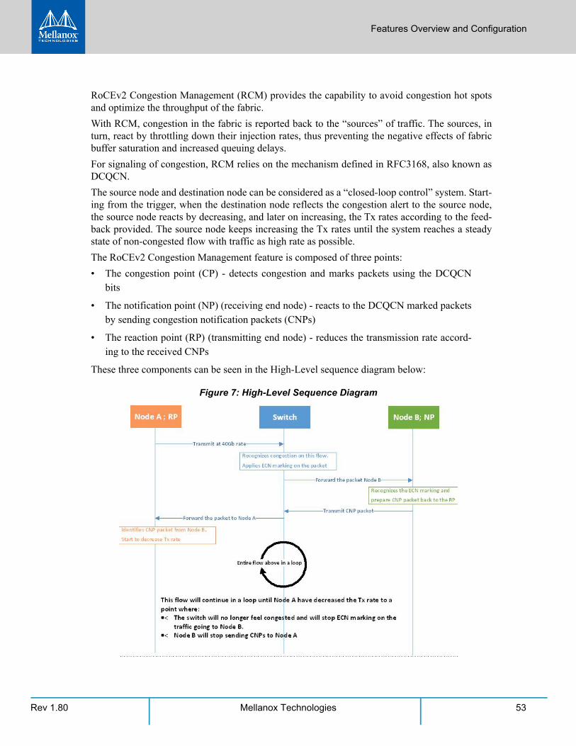
3.2.3 RoCEv2 Congestion Management (RCM) . . . . . . . . . . . . . . . . . . . . . . . . . . 523.2.3.1 Restrictions and Limitations . . . . . . . . . . . . . . . . . . . . . . . . . . . . . . . . . . . . 543.2.3.2 RCM Configuration . . . . . . . . . . . . . . . . . . . . . . . . . . . . . . . . . . . . . . . . . . . 543.2.3.3 RCM Parameters . . . . . . . . . . . . . . . . . . . . . . . . . . . . . . . . . . . . . . . . . . . . . 563.2.3.4 How Changing the Parameters Affect Congestion Control Behavior . . . 583.2.3.5 Mellanox Commands and Examples . . . . . . . . . . . . . . . . . . . . . . . . . . . . . 60
3.2.4 Teaming and VLAN . . . . . . . . . . . . . . . . . . . . . . . . . . . . . . . . . . . . . . . . . . . . 613.2.4.1 Configuring a Network to Work with VLAN in Windows Server 2012 and Above 61
3.2.5 Configuring Quality of Service (QoS) . . . . . . . . . . . . . . . . . . . . . . . . . . . . . . 623.2.5.1 QoS Configuration . . . . . . . . . . . . . . . . . . . . . . . . . . . . . . . . . . . . . . . . . . . . 623.2.5.2 Enhanced Transmission Selection . . . . . . . . . . . . . . . . . . . . . . . . . . . . . . . 65
3.2.6 Differentiated Services Code Point (DSCP) . . . . . . . . . . . . . . . . . . . . . . . . . 663.2.6.1 System Requirements . . . . . . . . . . . . . . . . . . . . . . . . . . . . . . . . . . . . . . . . . 663.2.6.2 Setting the DSCP in the IP Header . . . . . . . . . . . . . . . . . . . . . . . . . . . . . . . 663.2.6.3 Configuring Quality of Service for TCP and RDMA Traffic . . . . . . . . . . . . 663.2.6.4 Configuring DSCP to Control PFC for TCP Traffic. . . . . . . . . . . . . . . . . . . . 673.2.6.5 Configuring DSCP to Control ETS for TCP Traffic . . . . . . . . . . . . . . . . . . . . 673.2.6.6 Configuring DSCP to Control PFC for RDMA Traffic . . . . . . . . . . . . . . . . . 673.2.6.7 Receive Trust State . . . . . . . . . . . . . . . . . . . . . . . . . . . . . . . . . . . . . . . . . . . 683.2.6.8 Registry Settings . . . . . . . . . . . . . . . . . . . . . . . . . . . . . . . . . . . . . . . . . . . . . 68
3.2.7 Receive Segment Coalescing (RSC) . . . . . . . . . . . . . . . . . . . . . . . . . . . . . . . 693.2.8 Wake on LAN (WoL) . . . . . . . . . . . . . . . . . . . . . . . . . . . . . . . . . . . . . . . . . . . 703.2.9 Data Center Bridging Exchange (DCBX) . . . . . . . . . . . . . . . . . . . . . . . . . . . . 703.2.10 Receive Path Activity Monitoring . . . . . . . . . . . . . . . . . . . . . . . . . . . . . . . . 723.2.11 Head of Queue Lifetime Limit . . . . . . . . . . . . . . . . . . . . . . . . . . . . . . . . . . . 733.2.12 VXLAN . . . . . . . . . . . . . . . . . . . . . . . . . . . . . . . . . . . . . . . . . . . . . . . . . . . . . . 733.2.13 Threaded DPC . . . . . . . . . . . . . . . . . . . . . . . . . . . . . . . . . . . . . . . . . . . . . . . . 73
3.3 InfiniBand Network. . . . . . . . . . . . . . . . . . . . . . . . . . . . . . . . . . . . . . . . . . . . 753.3.1 Supported IPoIB Capabilities/Features . . . . . . . . . . . . . . . . . . . . . . . . . . . . 753.3.2 Unsupported IPoIB Capabilities/Features . . . . . . . . . . . . . . . . . . . . . . . . . . 75
3.4 Storage Protocols . . . . . . . . . . . . . . . . . . . . . . . . . . . . . . . . . . . . . . . . . . . . . 753.4.1 Deploying SMB Direct . . . . . . . . . . . . . . . . . . . . . . . . . . . . . . . . . . . . . . . . . . 75
3.4.1.1 SMB Configuration Verification . . . . . . . . . . . . . . . . . . . . . . . . . . . . . . . . . 753.4.1.2 Verifying SMB Events that Confirm RDMA Connection . . . . . . . . . . . . . . 76
3.5 Virtualization. . . . . . . . . . . . . . . . . . . . . . . . . . . . . . . . . . . . . . . . . . . . . . . . . 773.5.1 Hyper-V with VMQ . . . . . . . . . . . . . . . . . . . . . . . . . . . . . . . . . . . . . . . . . . . . 77
Rev 1.80 5Mellanox Technologies
3.5.1.1 System Requirements . . . . . . . . . . . . . . . . . . . . . . . . . . . . . . . . . . . . . . . . . 773.5.1.2 Using Hyper-V with VMQ . . . . . . . . . . . . . . . . . . . . . . . . . . . . . . . . . . . . . . 77
3.5.2 Network Virtualization using Generic Routing Encapsulation (NVGRE) . . 783.5.2.1 System Requirements . . . . . . . . . . . . . . . . . . . . . . . . . . . . . . . . . . . . . . . . . 783.5.2.2 Using NVGRE . . . . . . . . . . . . . . . . . . . . . . . . . . . . . . . . . . . . . . . . . . . . . . . . 783.5.2.3 Enabling/Disabling NVGRE Offloading . . . . . . . . . . . . . . . . . . . . . . . . . . . . 793.5.2.4 Verifying the Encapsulation of the Traffic . . . . . . . . . . . . . . . . . . . . . . . . . 803.5.2.5 Removing NVGRE configuration. . . . . . . . . . . . . . . . . . . . . . . . . . . . . . . . . 81
3.5.3 Single Root I/O Virtualization (SR-IOV) . . . . . . . . . . . . . . . . . . . . . . . . . . . . 813.5.3.1 SR-IOV over Hyper-V . . . . . . . . . . . . . . . . . . . . . . . . . . . . . . . . . . . . . . . . . . 823.5.3.2 Configuring SR-IOV Host Machines . . . . . . . . . . . . . . . . . . . . . . . . . . . . . . 823.5.3.3 Configuring Mellanox Network Adapter for SR-IOV . . . . . . . . . . . . . . . . . 903.5.3.4 Configuring IPoIB in SR-IOV. . . . . . . . . . . . . . . . . . . . . . . . . . . . . . . . . . . . . 923.5.3.5 Configuring Virtual Machine Networking (InfiniBand SR-IOV Only) . . . . 933.5.3.6 Configuring Virtual Machine Networking . . . . . . . . . . . . . . . . . . . . . . . . . 933.5.3.7 VF Spoof Protection. . . . . . . . . . . . . . . . . . . . . . . . . . . . . . . . . . . . . . . . . . . 97
3.5.4 Virtual Machine Multiple Queue (VMMQ) . . . . . . . . . . . . . . . . . . . . . . . . . 983.5.4.1 System Requirements . . . . . . . . . . . . . . . . . . . . . . . . . . . . . . . . . . . . . . . . . 993.5.4.2 Enabling/Disabling VMMQ . . . . . . . . . . . . . . . . . . . . . . . . . . . . . . . . . . . . . 993.5.4.3 Controlling the Number of Queues Allocated for a vPort . . . . . . . . . . . 101
3.5.5 Network Direct Kernel Provider Interface. . . . . . . . . . . . . . . . . . . . . . . . . 1013.5.5.1 System Requirement . . . . . . . . . . . . . . . . . . . . . . . . . . . . . . . . . . . . . . . . . 1013.5.5.2 Configuring NDK. . . . . . . . . . . . . . . . . . . . . . . . . . . . . . . . . . . . . . . . . . . . . 1013.5.5.3 Utility to Run and Monitor NDK . . . . . . . . . . . . . . . . . . . . . . . . . . . . . . . . 104
3.5.6 PacketDirect Provider Interface. . . . . . . . . . . . . . . . . . . . . . . . . . . . . . . . . 1053.5.6.1 System Requirements . . . . . . . . . . . . . . . . . . . . . . . . . . . . . . . . . . . . . . . . 1053.5.6.2 Using PacketDirect for VM . . . . . . . . . . . . . . . . . . . . . . . . . . . . . . . . . . . . 1053.5.6.3 Disable Loopback Mode . . . . . . . . . . . . . . . . . . . . . . . . . . . . . . . . . . . . . . 108
3.5.7 Data Plane Development Kit (DPDK) . . . . . . . . . . . . . . . . . . . . . . . . . . . . . 1093.5.7.1 General Background and References. . . . . . . . . . . . . . . . . . . . . . . . . . . . 1093.5.7.2 Flows Prerequisites . . . . . . . . . . . . . . . . . . . . . . . . . . . . . . . . . . . . . . . . . . 109
3.6 Configuring the Driver Registry Keys. . . . . . . . . . . . . . . . . . . . . . . . . . . . . 1093.6.1 Finding the Index Value of the Network Interface . . . . . . . . . . . . . . . . . . 1103.6.2 Basic Registry Keys . . . . . . . . . . . . . . . . . . . . . . . . . . . . . . . . . . . . . . . . . . . 1113.6.3 General Registry Keys. . . . . . . . . . . . . . . . . . . . . . . . . . . . . . . . . . . . . . . . . 1123.6.4 Offload Registry Keys . . . . . . . . . . . . . . . . . . . . . . . . . . . . . . . . . . . . . . . . . 1123.6.5 Performance Registry Keys. . . . . . . . . . . . . . . . . . . . . . . . . . . . . . . . . . . . . 1143.6.6 Ethernet Registry Keys . . . . . . . . . . . . . . . . . . . . . . . . . . . . . . . . . . . . . . . . 1183.6.7 RDMA Registry Keys . . . . . . . . . . . . . . . . . . . . . . . . . . . . . . . . . . . . . . . . . . 119
3.6.7.1 Flow Control Options. . . . . . . . . . . . . . . . . . . . . . . . . . . . . . . . . . . . . . . . . 1193.6.7.2 VMQ Options . . . . . . . . . . . . . . . . . . . . . . . . . . . . . . . . . . . . . . . . . . . . . . . 1193.6.7.3 RoCE Options . . . . . . . . . . . . . . . . . . . . . . . . . . . . . . . . . . . . . . . . . . . . . . . 1203.6.7.4 SR-IOV Options. . . . . . . . . . . . . . . . . . . . . . . . . . . . . . . . . . . . . . . . . . . . . . 120
Rev 1.806 Mellanox Technologies
3.6.8 Diagnostics Registry Keys . . . . . . . . . . . . . . . . . . . . . . . . . . . . . . . . . . . . . . 1213.6.8.1 Dump Me Now (DMN) Registry Keys . . . . . . . . . . . . . . . . . . . . . . . . . . . . 121
3.7 Network Direct Interface . . . . . . . . . . . . . . . . . . . . . . . . . . . . . . . . . . . . . . 1213.7.1 Test Running . . . . . . . . . . . . . . . . . . . . . . . . . . . . . . . . . . . . . . . . . . . . . . . . 122
3.8 Performance Tuning . . . . . . . . . . . . . . . . . . . . . . . . . . . . . . . . . . . . . . . . . . 1233.8.1 General Performance Optimization and Tuning. . . . . . . . . . . . . . . . . . . . 123
3.8.1.1 Registry Tuning . . . . . . . . . . . . . . . . . . . . . . . . . . . . . . . . . . . . . . . . . . . . . 1233.8.1.2 Enable RSS . . . . . . . . . . . . . . . . . . . . . . . . . . . . . . . . . . . . . . . . . . . . . . . . . 1243.8.1.3 Improving Live Migration . . . . . . . . . . . . . . . . . . . . . . . . . . . . . . . . . . . . . 124
3.8.2 Application Specific Optimization and Tuning . . . . . . . . . . . . . . . . . . . . . 1243.8.2.1 Ethernet Performance Tuning . . . . . . . . . . . . . . . . . . . . . . . . . . . . . . . . . 1243.8.2.2 Ethernet Bandwidth Improvements. . . . . . . . . . . . . . . . . . . . . . . . . . . . . 1243.8.2.3 IPoIB Performance Tuning . . . . . . . . . . . . . . . . . . . . . . . . . . . . . . . . . . . . 125
3.8.3 Tunable Performance Parameters. . . . . . . . . . . . . . . . . . . . . . . . . . . . . . . 1263.9 Adapter Cards Counters . . . . . . . . . . . . . . . . . . . . . . . . . . . . . . . . . . . . . . . 128
3.9.1 Mellanox WinOF-2 Port Traffic . . . . . . . . . . . . . . . . . . . . . . . . . . . . . . . . . 1283.9.2 Mellanox WinOF-2 VF Port Traffic . . . . . . . . . . . . . . . . . . . . . . . . . . . . . . . 1303.9.3 Mellanox WinOF-2 Port QoS . . . . . . . . . . . . . . . . . . . . . . . . . . . . . . . . . . . 1313.9.4 RDMA Activity . . . . . . . . . . . . . . . . . . . . . . . . . . . . . . . . . . . . . . . . . . . . . . . 1333.9.5 Mellanox WinOF-2 Congestion Control. . . . . . . . . . . . . . . . . . . . . . . . . . . 1333.9.6 Mellanox WinOF-2 Diagnostics . . . . . . . . . . . . . . . . . . . . . . . . . . . . . . . . . 1343.9.7 Mellanox WinOF-2 Device Diagnostic . . . . . . . . . . . . . . . . . . . . . . . . . . . . 1363.9.8 Mellanox WinOF-2 PCI Device Diagnostic . . . . . . . . . . . . . . . . . . . . . . . . . 1393.9.9 Mellanox WinOF-2 Rss Counters . . . . . . . . . . . . . . . . . . . . . . . . . . . . . . . . 140
3.10 Resiliency. . . . . . . . . . . . . . . . . . . . . . . . . . . . . . . . . . . . . . . . . . . . . . . . . . . 1413.10.1 Dump Me Now (DMN) . . . . . . . . . . . . . . . . . . . . . . . . . . . . . . . . . . . . . . . . 141
3.10.1.1 DMN Triggers and APIs . . . . . . . . . . . . . . . . . . . . . . . . . . . . . . . . . . . . . . . 1423.10.1.2 Dumps and Incident Folders . . . . . . . . . . . . . . . . . . . . . . . . . . . . . . . . . . . 1423.10.1.3 Cyclic DMN Mechanism . . . . . . . . . . . . . . . . . . . . . . . . . . . . . . . . . . . . . . 143
Chapter 4 Utilities . . . . . . . . . . . . . . . . . . . . . . . . . . . . . . . . . . . . . . . . . . . . . 1444.1 Fabric Performance Utilities . . . . . . . . . . . . . . . . . . . . . . . . . . . . . . . . . . . 144
4.1.1 Win-Linux nd_rping Test. . . . . . . . . . . . . . . . . . . . . . . . . . . . . . . . . . . . . . . 1454.2 Management Utilities. . . . . . . . . . . . . . . . . . . . . . . . . . . . . . . . . . . . . . . . . 145
4.2.1 mlx5cmd Utilities. . . . . . . . . . . . . . . . . . . . . . . . . . . . . . . . . . . . . . . . . . . . . 1454.2.1.1 Performance Tuning Utility. . . . . . . . . . . . . . . . . . . . . . . . . . . . . . . . . . . . 1464.2.1.2 Information Utility . . . . . . . . . . . . . . . . . . . . . . . . . . . . . . . . . . . . . . . . . . . 1464.2.1.3 Trace Utility . . . . . . . . . . . . . . . . . . . . . . . . . . . . . . . . . . . . . . . . . . . . . . . . 1464.2.1.4 QoS Configuration Utility . . . . . . . . . . . . . . . . . . . . . . . . . . . . . . . . . . . . . 1464.2.1.5 mstdump Utility . . . . . . . . . . . . . . . . . . . . . . . . . . . . . . . . . . . . . . . . . . . . . 1464.2.1.6 Registry Keys Utility . . . . . . . . . . . . . . . . . . . . . . . . . . . . . . . . . . . . . . . . . . 1474.2.1.7 Non-RSS Traffic Capture Utility. . . . . . . . . . . . . . . . . . . . . . . . . . . . . . . . . 1474.2.1.8 Sniffer Utility . . . . . . . . . . . . . . . . . . . . . . . . . . . . . . . . . . . . . . . . . . . . . . . 1474.2.1.9 Link Speed Utility . . . . . . . . . . . . . . . . . . . . . . . . . . . . . . . . . . . . . . . . . . . . 147
Rev 1.80 7Mellanox Technologies
4.2.1.10 NdStat Utility . . . . . . . . . . . . . . . . . . . . . . . . . . . . . . . . . . . . . . . . . . . . . . . 1484.3 Snapshot Utility. . . . . . . . . . . . . . . . . . . . . . . . . . . . . . . . . . . . . . . . . . . . . . 148
4.3.1 Snapshot Usage . . . . . . . . . . . . . . . . . . . . . . . . . . . . . . . . . . . . . . . . . . . . . . 148
Chapter 5 Troubleshooting. . . . . . . . . . . . . . . . . . . . . . . . . . . . . . . . . . . . . . 1865.1 Installation Related Troubleshooting . . . . . . . . . . . . . . . . . . . . . . . . . . . . 186
5.1.1 Installation Error Codes and Troubleshooting . . . . . . . . . . . . . . . . . . . . . 1865.1.1.1 Setup Return Codes. . . . . . . . . . . . . . . . . . . . . . . . . . . . . . . . . . . . . . . . . . 1865.1.1.2 Firmware Burning Warning Codes . . . . . . . . . . . . . . . . . . . . . . . . . . . . . . 1865.1.1.3 Restore Configuration Warnings . . . . . . . . . . . . . . . . . . . . . . . . . . . . . . . 187
5.2 InfiniBand Related Troubleshooting . . . . . . . . . . . . . . . . . . . . . . . . . . . . . 1885.3 Ethernet Related Troubleshooting . . . . . . . . . . . . . . . . . . . . . . . . . . . . . . 1885.4 Performance Related Troubleshooting. . . . . . . . . . . . . . . . . . . . . . . . . . . 190
5.4.1 General Diagnostic . . . . . . . . . . . . . . . . . . . . . . . . . . . . . . . . . . . . . . . . . . . 1905.5 Virtualization Related Troubleshooting . . . . . . . . . . . . . . . . . . . . . . . . . . 1915.6 Reported Driver Events . . . . . . . . . . . . . . . . . . . . . . . . . . . . . . . . . . . . . . . 1925.7 State Dumping . . . . . . . . . . . . . . . . . . . . . . . . . . . . . . . . . . . . . . . . . . . . . . 1985.8 Extracting WPP Traces . . . . . . . . . . . . . . . . . . . . . . . . . . . . . . . . . . . . . . . . 199
Appendix A NVGRE Configuration Scripts Examples . . . . . . . . . . . . . . . . . . 203A.1 Adding NVGRE Configuration to Host 14 Example . . . . . . . . . . . . . . . 203A.2 Adding NVGRE Configuration to Host 15 Example . . . . . . . . . . . . . . . 205
Appendix B Windows MPI (MS-MPI) . . . . . . . . . . . . . . . . . . . . . . . . . . . . . . 207B.1 Overview . . . . . . . . . . . . . . . . . . . . . . . . . . . . . . . . . . . . . . . . . . . . . . . . 207
B.2 System Requirements . . . . . . . . . . . . . . . . . . . . . . . . . . . . . . . . . . . . . . 207B.3 Running MPI. . . . . . . . . . . . . . . . . . . . . . . . . . . . . . . . . . . . . . . . . . . . . . 207B.4 Directing MSMPI Traffic . . . . . . . . . . . . . . . . . . . . . . . . . . . . . . . . . . . . 207B.5 Running MSMPI on the Desired Priority . . . . . . . . . . . . . . . . . . . . . . . 208B.6 Configuring MPI . . . . . . . . . . . . . . . . . . . . . . . . . . . . . . . . . . . . . . . . . . . 208
B.7 PFC Example. . . . . . . . . . . . . . . . . . . . . . . . . . . . . . . . . . . . . . . . . . . . . . 208B.8 Running MPI Command Examples . . . . . . . . . . . . . . . . . . . . . . . . . . . . 209
Rev 1.808 Mellanox Technologies
List of Tables
Table 1: Document Revision History. . . . . . . . . . . . . . . . . . . . . . . . . . . . . . . . . . . . . . . . . . . . 10Table 2: Documentation Conventions . . . . . . . . . . . . . . . . . . . . . . . . . . . . . . . . . . . . . . . . . . 18Table 3: Abbreviations and Acronyms . . . . . . . . . . . . . . . . . . . . . . . . . . . . . . . . . . . . . . . . . . 19Table 4: Related Documents . . . . . . . . . . . . . . . . . . . . . . . . . . . . . . . . . . . . . . . . . . . . . . . . . . 20Table 5: Reserved IP Address Options . . . . . . . . . . . . . . . . . . . . . . . . . . . . . . . . . . . . . . . . . . 35Table 6: Registry Keys Setting . . . . . . . . . . . . . . . . . . . . . . . . . . . . . . . . . . . . . . . . . . . . . . . . . 43Table 7: Registry Key Parameters . . . . . . . . . . . . . . . . . . . . . . . . . . . . . . . . . . . . . . . . . . . . . . 52Table 8: RCM Parameters . . . . . . . . . . . . . . . . . . . . . . . . . . . . . . . . . . . . . . . . . . . . . . . . . . . . 56Table 9: Default Priority Parameters . . . . . . . . . . . . . . . . . . . . . . . . . . . . . . . . . . . . . . . . . . . 58Table 10: DSCP to PCP Mapping . . . . . . . . . . . . . . . . . . . . . . . . . . . . . . . . . . . . . . . . . . . . . . . . 68Table 11: DSCP Registry Keys Settings . . . . . . . . . . . . . . . . . . . . . . . . . . . . . . . . . . . . . . . . . . . 68Table 12: DSCP Default Registry Keys Settings. . . . . . . . . . . . . . . . . . . . . . . . . . . . . . . . . . . . . 69Table 13: VF Spoof Protection Registry Keys . . . . . . . . . . . . . . . . . . . . . . . . . . . . . . . . . . . . . . 98Table 14: SR-IOV Support Limitations. . . . . . . . . . . . . . . . . . . . . . . . . . . . . . . . . . . . . . . . . . . . 99Table 15: Registry Key Groups. . . . . . . . . . . . . . . . . . . . . . . . . . . . . . . . . . . . . . . . . . . . . . . . .109Table 16: Basic Registry Keys. . . . . . . . . . . . . . . . . . . . . . . . . . . . . . . . . . . . . . . . . . . . . . . . . .111Table 17: General Registry Keys . . . . . . . . . . . . . . . . . . . . . . . . . . . . . . . . . . . . . . . . . . . . . . .112Table 18: Offload Registry Keys. . . . . . . . . . . . . . . . . . . . . . . . . . . . . . . . . . . . . . . . . . . . . . . .112Table 19: Performance Registry Keys . . . . . . . . . . . . . . . . . . . . . . . . . . . . . . . . . . . . . . . . . . .114Table 20: Ethernet Registry Keys. . . . . . . . . . . . . . . . . . . . . . . . . . . . . . . . . . . . . . . . . . . . . . .118Table 21: RDMA Registry Keys. . . . . . . . . . . . . . . . . . . . . . . . . . . . . . . . . . . . . . . . . . . . . . . . .119Table 22: Flow Control Options. . . . . . . . . . . . . . . . . . . . . . . . . . . . . . . . . . . . . . . . . . . . . . . .119Table 23: VMQ Options . . . . . . . . . . . . . . . . . . . . . . . . . . . . . . . . . . . . . . . . . . . . . . . . . . . . . .120Table 24: RoCE Options . . . . . . . . . . . . . . . . . . . . . . . . . . . . . . . . . . . . . . . . . . . . . . . . . . . . . .120Table 25: SR-IOV Options. . . . . . . . . . . . . . . . . . . . . . . . . . . . . . . . . . . . . . . . . . . . . . . . . . . . .121Table 26: Diagnostics Registry Keys . . . . . . . . . . . . . . . . . . . . . . . . . . . . . . . . . . . . . . . . . . . .121Table 27: Mellanox WinOF-2 Port Traffic . . . . . . . . . . . . . . . . . . . . . . . . . . . . . . . . . . . . . . . .128Table 28: Mellanox WinOF-2 VF Port Traffic . . . . . . . . . . . . . . . . . . . . . . . . . . . . . . . . . . . . .130Table 29: Mellanox WinOF-2 Port QoS . . . . . . . . . . . . . . . . . . . . . . . . . . . . . . . . . . . . . . . . . .131Table 30: RDMA Activity . . . . . . . . . . . . . . . . . . . . . . . . . . . . . . . . . . . . . . . . . . . . . . . . . . . . .133Table 31: Mellanox WinOF-2 Congestion Control . . . . . . . . . . . . . . . . . . . . . . . . . . . . . . . . .133Table 32: Mellanox WinOF-2 Diagnostics. . . . . . . . . . . . . . . . . . . . . . . . . . . . . . . . . . . . . . . .134
Rev 1.80 9Mellanox Technologies
Table 33: Mellanox WinOF-2 Device Diagnostics. . . . . . . . . . . . . . . . . . . . . . . . . . . . . . . . . .136Table 34: Mellanox WinOF-2 PCI Device Diagnostic . . . . . . . . . . . . . . . . . . . . . . . . . . . . . . .139Table 35: Mellanox WinOF-2 Rss Counters . . . . . . . . . . . . . . . . . . . . . . . . . . . . . . . . . . . . . .140Table 36: Fabric Performance Utilities . . . . . . . . . . . . . . . . . . . . . . . . . . . . . . . . . . . . . . . . . .144Table 37: Installation Related Issues. . . . . . . . . . . . . . . . . . . . . . . . . . . . . . . . . . . . . . . . . . . .186Table 38: Setup Return Codes . . . . . . . . . . . . . . . . . . . . . . . . . . . . . . . . . . . . . . . . . . . . . . . . .186Table 39: Firmware Burning Warning Codes . . . . . . . . . . . . . . . . . . . . . . . . . . . . . . . . . . . . .186Table 40: Restore Configuration Warnings . . . . . . . . . . . . . . . . . . . . . . . . . . . . . . . . . . . . . .187Table 41: InfiniBand Related Issues . . . . . . . . . . . . . . . . . . . . . . . . . . . . . . . . . . . . . . . . . . . .188Table 42: Ethernet Related Issues. . . . . . . . . . . . . . . . . . . . . . . . . . . . . . . . . . . . . . . . . . . . . .188Table 43: Performance Related Issues . . . . . . . . . . . . . . . . . . . . . . . . . . . . . . . . . . . . . . . . . .190Table 44: Virtualization Related Issues . . . . . . . . . . . . . . . . . . . . . . . . . . . . . . . . . . . . . . . . . .191Table 45: Reported Driver Errors . . . . . . . . . . . . . . . . . . . . . . . . . . . . . . . . . . . . . . . . . . . . . .192Table 46: Reported Driver Warnings . . . . . . . . . . . . . . . . . . . . . . . . . . . . . . . . . . . . . . . . . . .194Table 47: Events Causing Automatic State Dumps . . . . . . . . . . . . . . . . . . . . . . . . . . . . . . . .198
Rev 1.8010 Mellanox Technologies
Document Revision HistoryTable 1 - Document Revision History
Document Revision
Date Changes
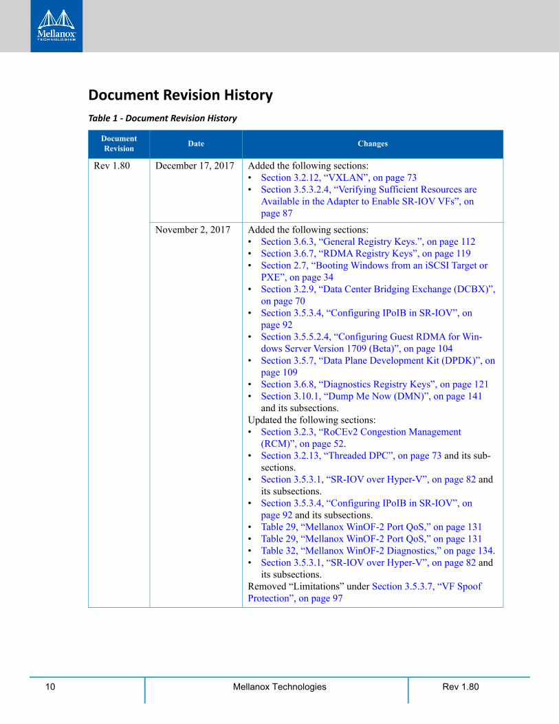
Rev 1.80 December 17, 2017 Added the following sections:• Section 3.2.12, “VXLAN”, on page 73• Section 3.5.3.2.4, “Verifying Sufficient Resources are
Available in the Adapter to Enable SR-IOV VFs”, on page 87
November 2, 2017 Added the following sections:• Section 3.6.3, “General Registry Keys.”, on page 112• Section 3.6.7, “RDMA Registry Keys”, on page 119• Section 2.7, “Booting Windows from an iSCSI Target or
PXE”, on page 34• Section 3.2.9, “Data Center Bridging Exchange (DCBX)”,
on page 70• Section 3.5.3.4, “Configuring IPoIB in SR-IOV”, on
page 92• Section 3.5.5.2.4, “Configuring Guest RDMA for Win-
dows Server Version 1709 (Beta)”, on page 104• Section 3.5.7, “Data Plane Development Kit (DPDK)”, on
page 109• Section 3.6.8, “Diagnostics Registry Keys”, on page 121• Section 3.10.1, “Dump Me Now (DMN)”, on page 141
and its subsections.Updated the following sections:• Section 3.2.3, “RoCEv2 Congestion Management
(RCM)”, on page 52.• Section 3.2.13, “Threaded DPC”, on page 73 and its sub-
sections.• Section 3.5.3.1, “SR-IOV over Hyper-V”, on page 82 and
its subsections.• Section 3.5.3.4, “Configuring IPoIB in SR-IOV”, on
page 92 and its subsections.• Table 29, “Mellanox WinOF-2 Port QoS,” on page 131• Table 29, “Mellanox WinOF-2 Port QoS,” on page 131• Table 32, “Mellanox WinOF-2 Diagnostics,” on page 134.• Section 3.5.3.1, “SR-IOV over Hyper-V”, on page 82 and
its subsections.Removed “Limitations” under Section 3.5.3.7, “VF Spoof Protection”, on page 97
Rev 1.80 11Mellanox Technologies
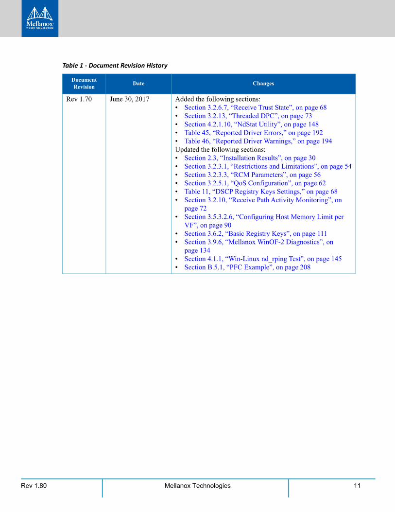
Rev 1.70 June 30, 2017 Added the following sections:• Section 3.2.6.7, “Receive Trust State”, on page 68• Section 3.2.13, “Threaded DPC”, on page 73• Section 4.2.1.10, “NdStat Utility”, on page 148• Table 45, “Reported Driver Errors,” on page 192• Table 46, “Reported Driver Warnings,” on page 194Updated the following sections:• Section 2.3, “Installation Results”, on page 30• Section 3.2.3.1, “Restrictions and Limitations”, on page 54• Section 3.2.3.3, “RCM Parameters”, on page 56• Section 3.2.5.1, “QoS Configuration”, on page 62• Table 11, “DSCP Registry Keys Settings,” on page 68• Section 3.2.10, “Receive Path Activity Monitoring”, on
page 72• Section 3.5.3.2.6, “Configuring Host Memory Limit per
VF”, on page 90• Section 3.6.2, “Basic Registry Keys”, on page 111• Section 3.9.6, “Mellanox WinOF-2 Diagnostics”, on
page 134• Section 4.1.1, “Win-Linux nd_rping Test”, on page 145• Section B.5.1, “PFC Example”, on page 208
Table 1 - Document Revision History
Document Revision
Date Changes
Rev 1.8012 Mellanox Technologies
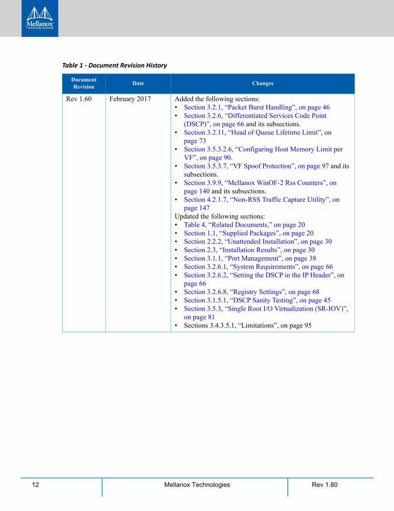
Rev 1.60 February 2017 Added the following sections:• Section 3.2.1, “Packet Burst Handling”, on page 46• Section 3.2.6, “Differentiated Services Code Point
(DSCP)”, on page 66 and its subsections.• Section 3.2.11, “Head of Queue Lifetime Limit”, on
page 73• Section 3.5.3.2.6, “Configuring Host Memory Limit per
VF”, on page 90.• Section 3.5.3.7, “VF Spoof Protection”, on page 97 and its
subsections.• Section 3.9.9, “Mellanox WinOF-2 Rss Counters”, on
page 140 and its subsections.• Section 4.2.1.7, “Non-RSS Traffic Capture Utility”, on
page 147 Updated the following sections:• Table 4, “Related Documents,” on page 20• Section 1.1, “Supplied Packages”, on page 20• Section 2.2.2, “Unattended Installation”, on page 30• Section 2.3, “Installation Results”, on page 30• Section 3.1.1, “Port Management”, on page 38• Section 3.2.6.1, “System Requirements”, on page 66• Section 3.2.6.2, “Setting the DSCP in the IP Header”, on
page 66• Section 3.2.6.8, “Registry Settings”, on page 68• Section 3.1.5.1, “DSCP Sanity Testing”, on page 45• Section 3.5.3, “Single Root I/O Virtualization (SR-IOV)”,
on page 81• Sections 3.4.3.5.1, “Limitations”, on page 95
Table 1 - Document Revision History
Document Revision
Date Changes
Rev 1.80 13Mellanox Technologies
Rev 1.60 2017 • Section 3.5.5.3.2, “Validating NDK”, on page 105• Section 3.6.1, “Finding the Index Value of the Network
Interface”, on page 110• Section 3.6.7.4, “SR-IOV Options”, on page 120• Section 3.8.2.2, “Ethernet Bandwidth Improvements”, on
page 124• Section 3.9.5, “Mellanox WinOF-2 Congestion Control”,
on page 133• Section 3.9.6, “Mellanox WinOF-2 Diagnostics”, on
page 134• Section 3.9.7, “Mellanox WinOF-2 Device Diagnostic”, on
page 136• Section 3.9.8, “Mellanox WinOF-2 PCI Device Diagnos-
tic”, on page 139• Section 4.1.1, “Win-Linux nd_rping Test”, on page 145• Table 20, “Ethernet Registry Keys,” on page 118• Section 5.2, “InfiniBand Related Troubleshooting”, on
page 188 • Section 5.7, “State Dumping”, on page 198 • Section A, “NVGRE Configuration Scripts Examples”, on
page 203• Section B, “Windows MPI (MS-MPI)”, on page 207Relocated the following section:• Section 3.7, “Network Direct Interface”, on page 143 (for-
merly 3.5.6) and its subsection.
Table 1 - Document Revision History
Document Revision
Date Changes
Rev 1.8014 Mellanox Technologies
Rev 1.50 November 2016 Added the following sections:• Section 3.2.10, “Receive Path Activity Monitoring”, on
page 72• Section 3.3, “InfiniBand Network”, on page 75• Section 3.5.6.3, “Disable Loopback Mode”, on page 108• Section 3.6.7.4, “SR-IOV Options”, on page 120• Section 3.9.5, “Mellanox WinOF-2 Congestion Control”,
on page 133• Section 3.9.7, “Mellanox WinOF-2 Device Diagnostic”, on
page 136• Section 3.8.2.2, “Ethernet Bandwidth Improvements”, on
page 124Updated the following sections:• Section , “About this Manual”, on page 18• Section 1, “Introduction”, on page 22• Section 1.1, “Supplied Packages”, on page 20• Section 2.1, “Hardware and Software Requirements”, on
page 21• Section 2.9.2, “Online Update”, on page 39• Section 3.1.1, “Port Management”, on page 38• Section 3.1.2.1, “Configuring 56GbE Link Speed”, on
page 41• Section 3.2.3, “RoCEv2 Congestion Management
(RCM)”, on page 52
Table 1 - Document Revision History
Document Revision
Date Changes
Rev 1.80 15Mellanox Technologies
• Section 3.2.3.1, “Restrictions and Limitations”, on page 54• Section 3.2.3.3, “RCM Parameters”, on page 56• Section 3.1.5.3.1, “RCM Default Parameters”, on page 51• Section 3.2.3.4.1, “CNP Priority”, on page 58• Section 3.2.3.4.2, “alpha -”α” = Rate Reduction Factor”,
on page 58• Section 3.2.3.4.3, “Decrease (on the “RP”)”, on page 59• Section 3.2.3.5, “Mellanox Commands and Examples”, on
page 60• Section 3.2.10, “Receive Segment Coalescing (RSC)”, on
page 69• Section 3.3.2, “Unsupported IPoIB Capabilities/Features”,
on page 75• Section 3.4.1.2, “Verifying SMB Events that Confirm
RDMA Connection”, on page 76• Section 3.5.2, “Network Virtualization using Generic
Routing Encapsulation (NVGRE)”, on page 78• Section 3.5.4, “Virtual Machine Multiple Queue
(VMMQ)”, on page 98• Section 3.5.4.1, “System Requirements”, on page 99• Section 3.5.4.2.1, “On the Driver Level”, on page 99• Section 3.5.6.3, “Disable Loopback Mode”, on page 108• Section 3.6.4, “Offload Registry Keys”, on page 112• Section 3.6.6, “Ethernet Registry Keys”, on page 118• Section 3.9.1.1, “Proprietary Mellanox WinOF-2 Port
Traffic Counters”, on page 137• Section 3.9.5, “Mellanox WinOF-2 Congestion Control”,
on page 133• Section 3.9.6, “Mellanox WinOF-2 Diagnostics”, on
page 134• Table 34, “Mellanox WinOF-2 PCI Device Diagnostic,” on
page 139• Table 36, “Fabric Performance Utilities,” on page 144• Section 4.1.1, “Win-Linux nd_rping Test”, on page 145• Section 4.2.1.4, “QoS Configuration Utility”, on page 146• Section 5.5, “Virtualization Related Troubleshooting”, on
page 191
Table 1 - Document Revision History
Document Revision
Date Changes
Rev 1.8016 Mellanox Technologies
Rev 1.45 September 2016 Added the following sections:• Section 4.2.1.9, “Link Speed Utility”, on page 147• Section 2.9.1, “Offline Installation”, on page 38• Section 2.9.2, “Online Update”, on page 39• Section 3.5.4, “Virtual Machine Multiple Queue
(VMMQ)”, on page 98• Section 3.5.5, “Network Direct Kernel Provider Interface”,
on page 101• Section 3.5.6, “PacketDirect Provider Interface”, on
page 105
Rev 1.40 May 2016 Added the following sections:• Section 4.2.1.6, “Registry Keys Utility”, on page 147• Section 4.2.1.7, “Non-RSS Traffic Capture Utility”, on
page 147• Section 4.2.1, “mlx5cmd Utilities”, on page 145• Section 3.2.9, “Data Center Bridging Exchange (DCBX)”,
on page 70• Section 3.2.10, “Receive Segment Coalescing (RSC)”, on
page 69• Section 4.1.1, “Win-Linux nd_rping Test”, on page 145• Section 5.8, “Extracting WPP Traces”, on page 199Updated the following sections:• Section 3.2.3.3, “RCM Parameters”, on page 56
Rev 1.35 January 2016 Added the following sections:• Section 3.2.3, “RoCEv2 Congestion Management
(RCM)”, on page 52• Section 3.9.5, “Mellanox WinOF-2 Congestion Control”,
on page 133• Section , “”, on page 133• Section 4.2.1.4, “QoS Configuration Utility”, on page 146• Section 4.2.1.5, “mstdump Utility”, on page 146• Section 4.3, “Snapshot Utility”, on page 148Updated the following sections:• Section 3.2.2.6, “Configuring the RoCE Mode”, on
page 51• Section 5.6, “Reported Driver Events”, on page 192• Section 5.7, “State Dumping”, on page 198
Table 1 - Document Revision History
Document Revision
Date Changes

Rev 1.80 17Mellanox Technologies
Rev 1.30 November 2015 Updated the following sections:• Section 4.2, “Management Utilities”, on page 145• Section 5.6, “Reported Driver Events”, on page 192• Section , “Common Abbreviations and Acronyms”, on
page 19Added the following sections: • Section 3.9, “Adapter Cards Counters”, on page 128
Rev 1.21 September 2015 Added the following section: • Section 3.5.3, “Single Root I/O Virtualization (SR-IOV)”,
on page 81
Updated the version number format - The UM version format was composed of three numbers: major, minor and sub-minor. The sub-minor version was removed from the UM.
Rev 1.20 September, 2015 Added the following sections:• Section 2.1, “Downloading Mellanox WinOF-2 Driver”,
on page 24• Section 3.5, “Virtualization”, on page 77• Section 5.5, “Virtualization Related Troubleshooting”, on
page 191• Appendix A,“NVGRE Configuration Scripts Examples,”
on page 203• Section 3.1.1, “Port Management”• Section 4.2, “Management Utilities”
Rev 1.10 July 8, 2015 Updated the following sections: • Section 1, “Introduction”, on page 22• Section 3.2.2.1, “IP Routable (RoCEv2)”, on page 46• Section 3.2.2.6, “Configuring the RoCE Mode”, on
page 51
Rev 1.10 June 2015 Beta Release
Table 1 - Document Revision History
Document Revision
Date Changes
Rev 1.8018 Mellanox Technologies
About this Manual
ScopeMellanox WinOF-2 is the Windows driver for Mellanox ConnectX®-4 and onwards adapter cards. It does not support earlier Mellanox adapter generations.
The document describes WinOF-2 Rev 1.80 features, performance, diagnostic tools, content and configuration. Additionally, this document provides information on various performance tools supplied with this version.
Intended AudienceThis manual is intended for system administrators responsible for the installation, configuration, management and maintenance of the software and hardware of Ethernet and InfiniBand adapter cards. It is also intended for application developers.
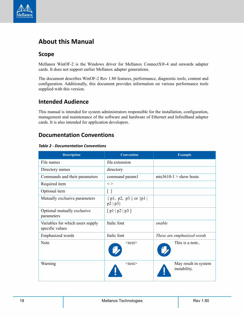
Documentation Conventions
Table 2 - Documentation Conventions
Description Convention Example
File names file.extension
Directory names directory
Commands and their parameters command param1 mts3610-1 > show hosts
Required item < >
Optional item [ ]
Mutually exclusive parameters { p1, p2, p3 } or {p1 | p2 | p3}
Optional mutually exclusive parameters
[ p1 | p2 | p3 ]
Variables for which users supply specific values
Italic font enable
Emphasized words Italic font These are emphasized words
Note <text> This is a note..
Warning <text> May result in system instability.
Rev 1.80 19Mellanox Technologies
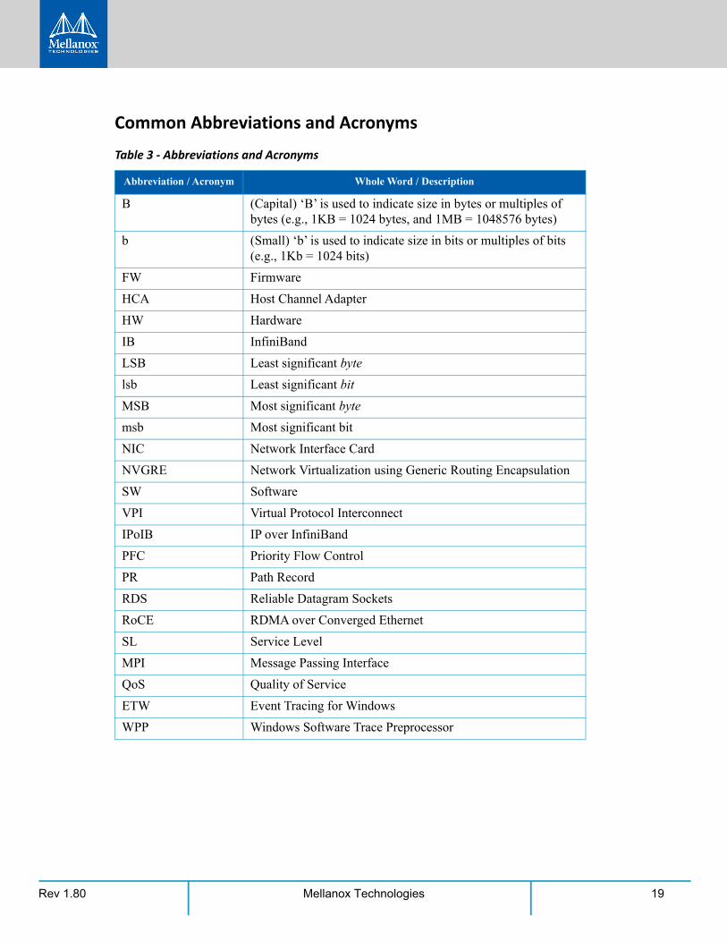
Common Abbreviations and Acronyms
Table 3 - Abbreviations and Acronyms
Abbreviation / Acronym Whole Word / Description
B (Capital) ‘B’ is used to indicate size in bytes or multiples of bytes (e.g., 1KB = 1024 bytes, and 1MB = 1048576 bytes)
b (Small) ‘b’ is used to indicate size in bits or multiples of bits (e.g., 1Kb = 1024 bits)
FW Firmware
HCA Host Channel Adapter
HW Hardware
IB InfiniBand
LSB Least significant byte
lsb Least significant bit
MSB Most significant byte
msb Most significant bit
NIC Network Interface Card
NVGRE Network Virtualization using Generic Routing Encapsulation
SW Software
VPI Virtual Protocol Interconnect
IPoIB IP over InfiniBand
PFC Priority Flow Control
PR Path Record
RDS Reliable Datagram Sockets
RoCE RDMA over Converged Ethernet
SL Service Level
MPI Message Passing Interface
QoS Quality of Service
ETW Event Tracing for Windows
WPP Windows Software Trace Preprocessor
Rev 1.8020 Mellanox Technologies
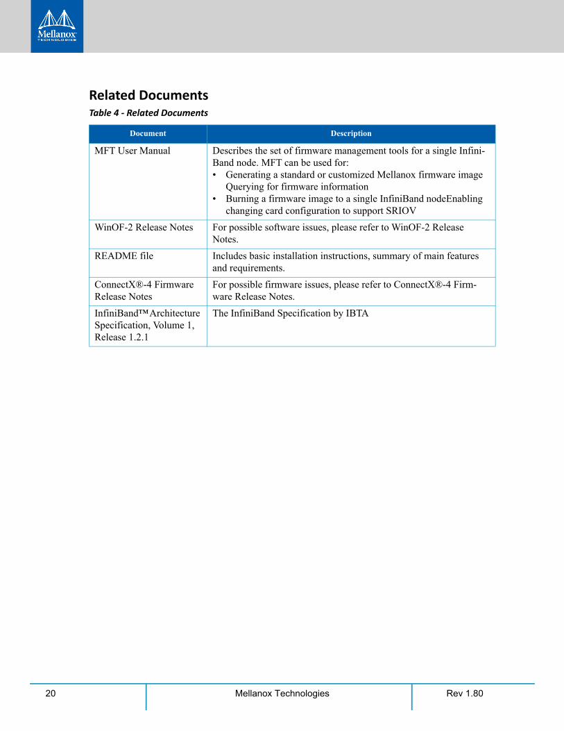
Related DocumentsTable 4 - Related Documents
Document Description
MFT User Manual Describes the set of firmware management tools for a single Infini-Band node. MFT can be used for:• Generating a standard or customized Mellanox firmware image
Querying for firmware information• Burning a firmware image to a single InfiniBand nodeEnabling
changing card configuration to support SRIOV
WinOF-2 Release Notes For possible software issues, please refer to WinOF-2 Release Notes.
README file Includes basic installation instructions, summary of main features and requirements.
ConnectX®-4 Firmware Release Notes
For possible firmware issues, please refer to ConnectX®-4 Firm-ware Release Notes.
InfiniBand™ Architecture Specification, Volume 1, Release 1.2.1
The InfiniBand Specification by IBTA

Rev 1.80 21Mellanox Technologies
Rev 1.8022 Mellanox Technologies
1 IntroductionThis User Manual describes installation, configuration and operation of Mellanox WinOF-2 driver Rev 1.80 package.
Mellanox WinOF-2 is composed of several software modules that contain InfiniBand and Ether-net drivers. It supports 10, 25, 40, 50 or 100 Gb/s Ethernet, and 40, 56 or 100 Gb/s InfiniBand network ports. The port type and speed are determined upon boot based on card capabilities and user settings.
The Mellanox WinOF-2 driver release introduces the following capabilities:
• General applicabilities:
• Support for Single and Dual port Adapters
• Receive Side Scaling (RSS)
• Hardware Tx/Rx checksum offload
• Large Send Offload (LSO)
• Adaptive interrupt moderation
• Support for MSI-X interrupts
• Network Direct Kernel (NDK) with support for SMBDirect
• Virtual Machine Queue (VMQ) for Hyper-V
• Quality of Service (QoS)
• Support for global flow control and Priority Flow Control (PFC)
• Enhanced Transmission Selection (ETS)
• Ethernet capabilities:
• Receive Side Coalescing (RSC)
• Hardware VLAN filtering
• RDMA over Converged Ethernet
• RoCE MAC Based (v1)
• RoCE IP Based (v1)
• RoCE over UDP (v2)
• VXLAN
• NDKPI v2.0
• VMMQ
• PacketDirect Provider Interface (PDPI)
• NVGRE hardware encapsulation task offload
• Single Root I/O Virtualization (SR-IOV)
• InfiniBand capabilities:

Introduction
Rev 1.80 23Mellanox Technologies
• Receive Side Scaling
• Checksum Offloads
For the complete list of Ethernet and InfiniBand Known Issues and Limitations, refer to the latest WinOF-2 Release Notes (www.mellanox.com -> Products -> Software -> InfiniBand/VPI Driv-ers -> Windows SW/Drivers).
Rev 1.8024 Mellanox Technologies
2 WinOF-2 Driver Installation
2.1 Downloading Mellanox WinOF-2 DriverTo download the .exe according to your Operating System, please follow the steps below:
Step 1. Obtain the machine architecture.
1. To go to the Start menu, position your mouse in the bottom-right corner of the Remote Desktop of your screen.
2. Open a CMD console (Click Task Manager-->File --> Run new task, and enter CMD).
3. Enter the following command.
On an x64 (64-bit) machine, the output will be “AMD64”.
Step 2. Go to the Mellanox WinOF-2 web page at: http://www.mellanox.com > Products > InfiniBand/VPI Drivers => Windows SW/Drivers.
Step 3. Download the .exe image according to the architecture of your machine (see Step 1). The name of the .exe is in the following format MLNX_WinOF2-<version>_<arch>.exe.
2.2 Installing Mellanox WinOF-2 Driver
This section provides instructions for two types of installation procedures:
• “Attended Installation”
An installation procedure that requires frequent user intervention.
• “Unattended Installation”
The snapshots in the following sections are presented for illustration purposes only. The installa-tion interface may slightly vary, depending on the used operating system.
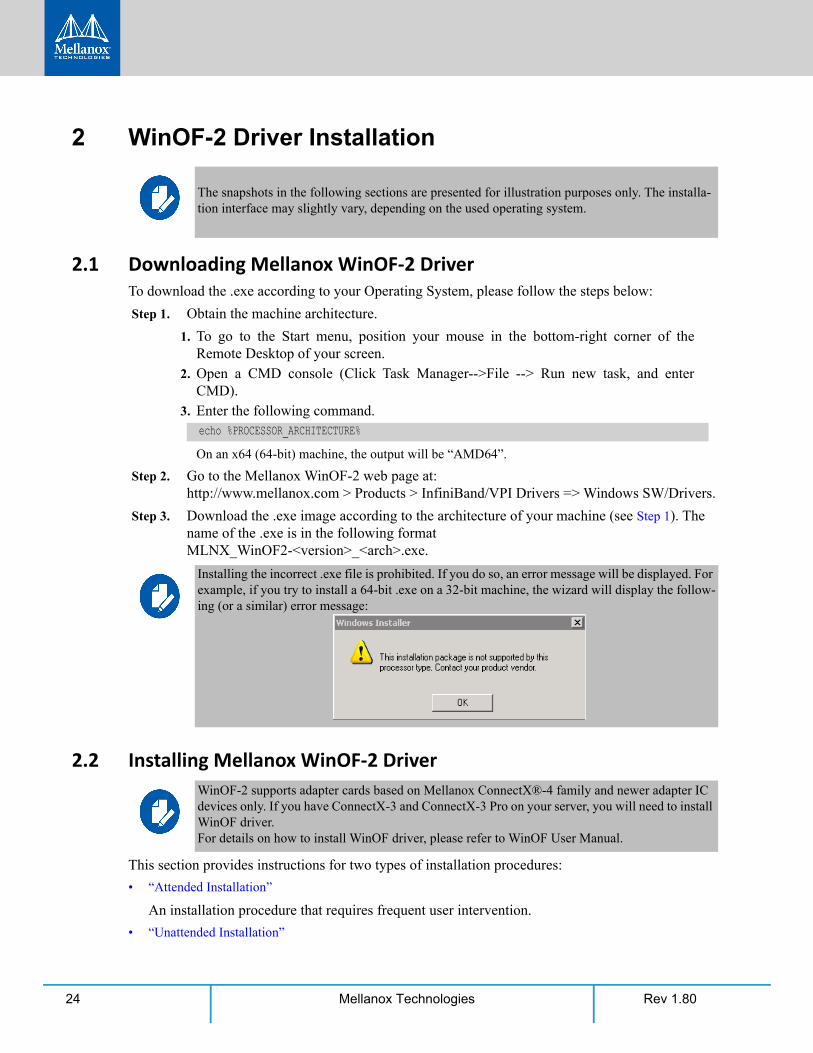
echo %PROCESSOR_ARCHITECTURE%
Installing the incorrect .exe file is prohibited. If you do so, an error message will be displayed. For example, if you try to install a 64-bit .exe on a 32-bit machine, the wizard will display the follow-ing (or a similar) error message:
WinOF-2 supports adapter cards based on Mellanox ConnectX®-4 family and newer adapter IC devices only. If you have ConnectX-3 and ConnectX-3 Pro on your server, you will need to install WinOF driver. For details on how to install WinOF driver, please refer to WinOF User Manual.
WinOF-2 Driver Installation
Rev 1.80 25Mellanox Technologies
An automated installation procedure that requires no user intervention.
2.2.1 Attended InstallationThe following is an example of an installation session.
Step 1. Double click the .exe and follow the GUI instructions to install MLNX_WinOF2.
Step 2. [Optional] Manually configure your setup to contain the logs option (replace “LogFile” with the relevant directory):.
Step 3. [Optional] If you do not want to upgrade your firmware version1.
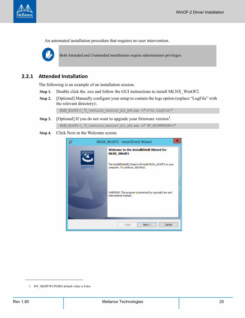
Step 4. Click Next in the Welcome screen.
Both Attended and Unattended installations require administrator privileges.
MLNX_WinOF2-1_70_<revision_version>_All_x64.exe /v"/l*vx [LogFile]"
MLNX_WinOF2-1_70_<revision_version>_All_x64.exe /v" MT_SKIPFWUPGRD=1"
1. MT_SKIPFWUPGRD default value is False
Rev 1.8026 Mellanox Technologies
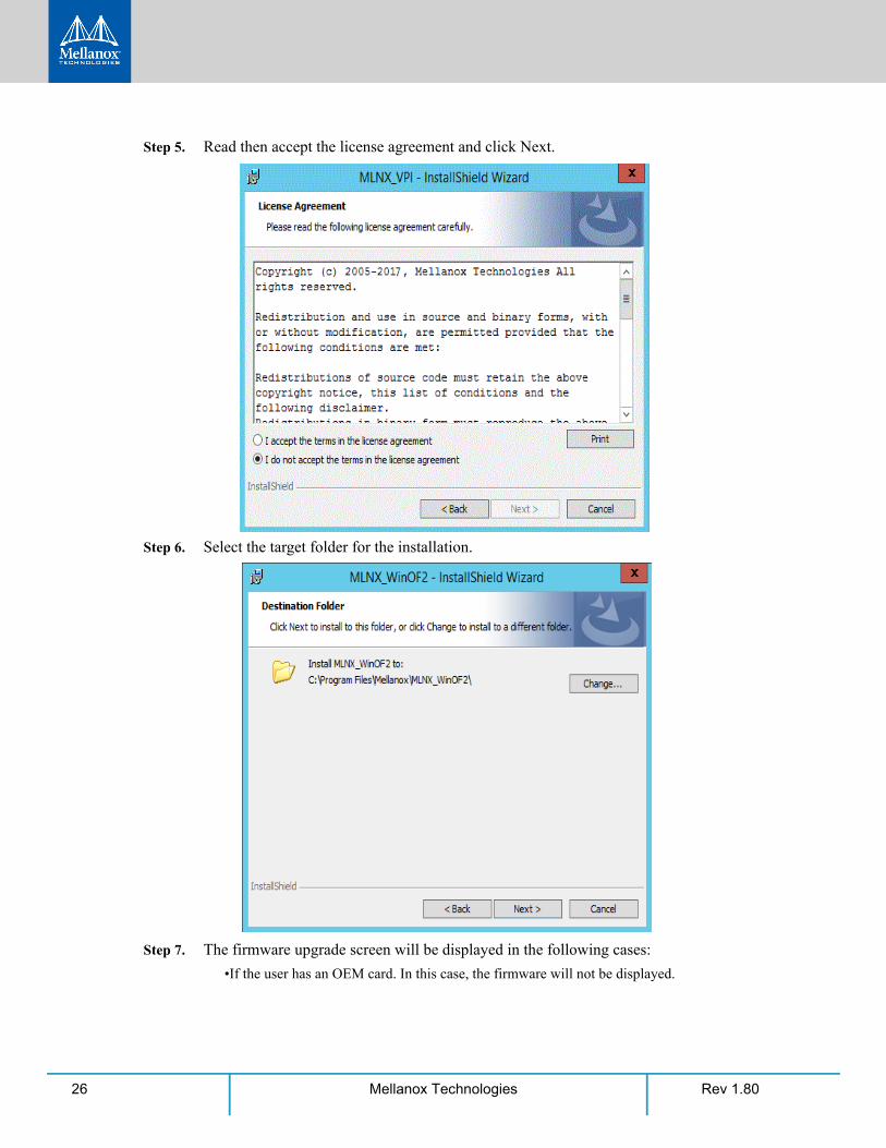
Step 5. Read then accept the license agreement and click Next.
Step 6. Select the target folder for the installation.
Step 7. The firmware upgrade screen will be displayed in the following cases:
•If the user has an OEM card. In this case, the firmware will not be displayed.
WinOF-2 Driver Installation
Rev 1.80 27Mellanox Technologies
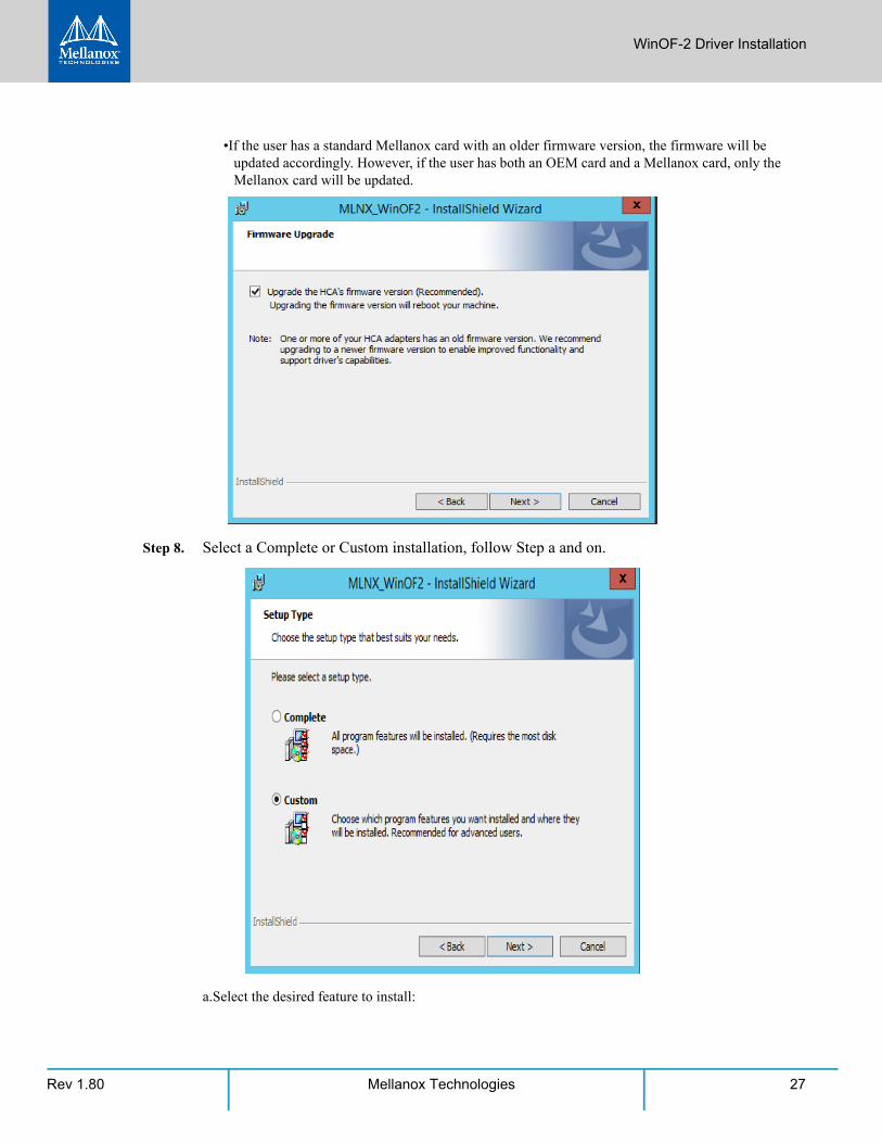
•If the user has a standard Mellanox card with an older firmware version, the firmware will be updated accordingly. However, if the user has both an OEM card and a Mellanox card, only the Mellanox card will be updated.
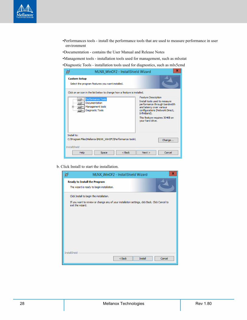
Step 8. Select a Complete or Custom installation, follow Step a and on.
a.Select the desired feature to install:
Rev 1.8028 Mellanox Technologies
•Performances tools - install the performance tools that are used to measure performance in user environment
•Documentation - contains the User Manual and Release Notes
•Management tools - installation tools used for management, such as mlxstat
•Diagnostic Tools - installation tools used for diagnostics, such as mlx5cmd
b. Click Install to start the installation.
WinOF-2 Driver Installation
Rev 1.80 29Mellanox Technologies
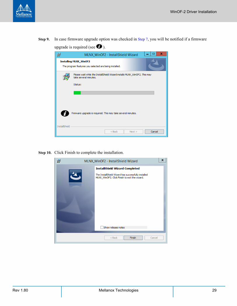
Step 9. In case firmware upgrade option was checked in Step 7, you will be notified if a firmware
upgrade is required (see ).
Step 10. Click Finish to complete the installation.
Rev 1.8030 Mellanox Technologies
2.2.2 Unattended Installation
The following is an example of an unattended installation session.
Step 1. Open a CMD console-> Click Start-> Task Manager File-> Run new task-> and enter CMD.
Step 2. Install the driver. Run:
Step 3. [Optional] Manually configure your setup to contain the logs option:
Step 4. [Optional] if you wish to control whether to install ND provider or not1.
Step 5. [Optional] If you do not wish to upgrade your firmware version2.
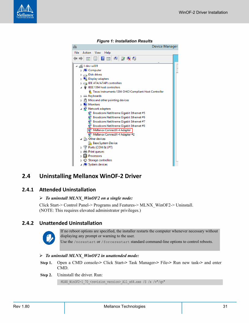
2.3 Installation ResultsUpon installation completion, you can verify the successful addition of the network card(s) through the Device Manager.
Upon installation completion, the inf files can be located at:
• %ProgramFiles%\Mellanox\MLNX_WinOF2\Drivers\
To see the Mellanox network adapters, display the Device Manager and pull down the “Network adapters” menu.
If no reboot options are specified, the installer restarts the computer whenever necessary without displaying any prompt or warning to the user.
Use the /norestart or /forcerestart standard command-line options to control reboots.
MLNX_WinOF2-1_70_<revision_version>_All_x64.exe /S /v/qn
MLNX_WinOF2-1_70_<revision_version>_All_x64.exe /S /v/qn /v”/l*vx [LogFile]"
MLNX_WinOF2-1_70_<revision_version>_All_x64.exe /vMT_NDPROPERTY=1
1. MT_NDPROPERTY default value is True
MLNX_WinOF2-1_70_<revision_version>_All_x64.exe /vMT_SKIPFWUPGRD=1
2. MT_SKIPFWUPGRD default value is False
Applications that hold the driver files (such as ND applications) will be closed during the unat-tended installation.
WinOF-2 Driver Installation
Rev 1.80 31Mellanox Technologies
Figure 1: Installation Results
2.4 Uninstalling Mellanox WinOF-2 Driver
2.4.1 Attended Uninstallation To uninstall MLNX_WinOF2 on a single node:
Click Start-> Control Panel-> Programs and Features-> MLNX_WinOF2-> Uninstall. (NOTE: This requires elevated administrator privileges.)
2.4.2 Unattended Uninstallation
To uninstall MLNX_WinOF2 in unattended mode:
Step 1. Open a CMD console-> Click Start-> Task Manager-> File-> Run new task-> and enter CMD.
Step 2. Uninstall the driver. Run:
If no reboot options are specified, the installer restarts the computer whenever necessary without displaying any prompt or warning to the user.
Use the /norestart or /forcerestart standard command-line options to control reboots.
MLNX_WinOF2-1_70_<revision_version>_All_x64.exe /S /x /v"/qn"
Rev 1.8032 Mellanox Technologies
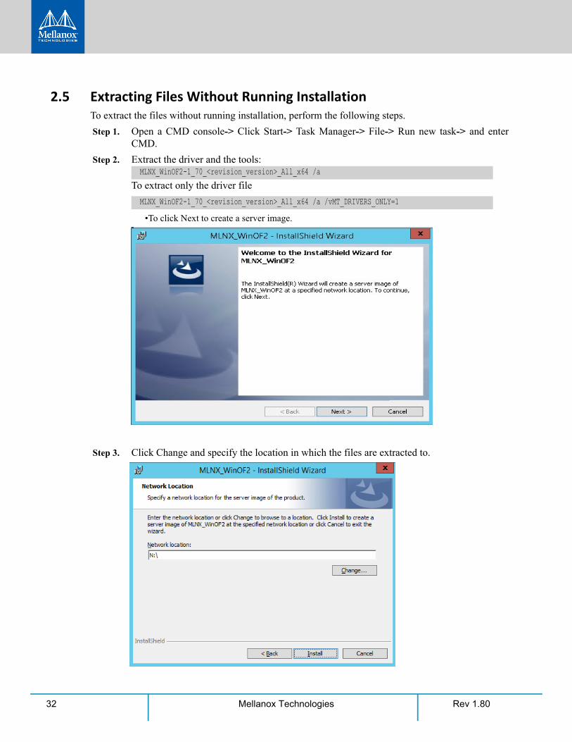
2.5 Extracting Files Without Running InstallationTo extract the files without running installation, perform the following steps.
Step 1. Open a CMD console-> Click Start-> Task Manager-> File-> Run new task-> and enter CMD.
Step 2. Extract the driver and the tools:
To extract only the driver file
•To click Next to create a server image.
Step 3. Click Change and specify the location in which the files are extracted to.
MLNX_WinOF2-1_70_<revision_version>_All_x64 /a
MLNX_WinOF2-1_70_<revision_version>_All_x64 /a /vMT_DRIVERS_ONLY=1

WinOF-2 Driver Installation
Rev 1.80 33Mellanox Technologies
Step 4. Click Install to extract this folder, or click Change to install to a different folder.
Step 5. To complete the extraction, click Finish.
2.6 Firmware UpgradeIf the machine has a standard Mellanox card with an older firmware version, the firmware will be automatically updated as part of the WinOF-2 package installation.
For information on how to upgrade firmware manually, please refer to MFT User Manual: www.mellanox.com ->Products -> InfiniBand/VPI Drivers -> Firmware Tools

Rev 1.8034 Mellanox Technologies
2.7 Booting Windows from an iSCSI Target or PXE
2.7.1 Configuring the WDS, DHCP and iSCSI Servers
2.7.1.1 Configuring the WDS Server
To configure the WDS server:
1. Install the WDS server.
2. Extract the Mellanox drivers to a local directory using the '-a' parameter.
Example:
3. Add the Mellanox driver to boot.wim1.
4. Add the Mellanox driver to install.wim2.
5. Add the new boot and install images to WDS.
For additional details on WDS, please refer to:
http://technet.microsoft.com/en-us/library/jj648426.aspx
2.7.1.2 Configuring iSCSI Target
To configure iSCSI Target:
1. Install iSCSI Target (e.g StartWind).
2. Add to the iSCSI target initiators the IP addresses of the iSCSI clients.
2.7.1.3 Configuring the DHCP Server
To configure the DHCP server:
1. Install a DHCP server.
2. Add to IPv4 a new scope.
Note: SAN network boot is not supported.
Mellanox.msi.exe -a
dism /Mount-Wim /WimFile:boot.wim /index:2 /MountDir:mntdism /Image:mnt /Add-Driver /Driver:drivers /recursedism /Unmount-Wim /MountDir:mnt /commit
1. Use ‘index:2’ for Windows setup and ‘index:1’for WinPE.
dism /Mount-Wim /WimFile:install.wim /index:4 /MountDir:mntdism /Image:mnt /Add-Driver /Driver:drivers /recursedism /Unmount-Wim /MountDir:mnt /commit
2. When adding the Mellanox driver to install.wim, verify you are using the appropriate index for your OS flavor. To check the OS run ‘imagex /info install.win’.
WinOF-2 Driver Installation
Rev 1.80 35Mellanox Technologies
3. Add boot client identifier (MAC/GUID) to the DHCP reservation.
4. Add to the reserved IP address the following options if DHCP and WDS are deployed on the same server:
2.7.2 Configuring the Client MachineTo configure your client, set the “Mellanox Adapter Card” as the first boot device in the BIOS settings boot order.
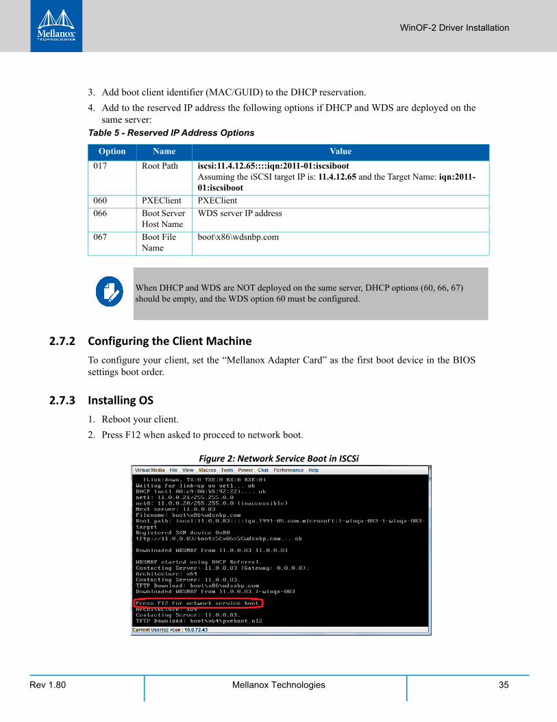
2.7.3 Installing OS1. Reboot your client.
2. Press F12 when asked to proceed to network boot.
Figure 2: Network Service Boot in ISCSi
Table 5 - Reserved IP Address Options
Option Name Value
017 Root Path iscsi:11.4.12.65::::iqn:2011-01:iscsibootAssuming the iSCSI target IP is: 11.4.12.65 and the Target Name: iqn:2011-01:iscsiboot
060 PXEClient PXEClient
066 Boot Server Host Name
WDS server IP address
067 Boot File Name
boot\x86\wdsnbp.com
When DHCP and WDS are NOT deployed on the same server, DHCP options (60, 66, 67) should be empty, and the WDS option 60 must be configured.
Rev 1.8036 Mellanox Technologies
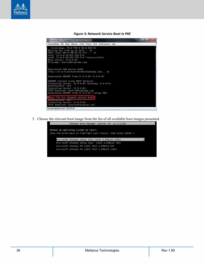
Figure 3: Network Service Boot in PXE
3. Choose the relevant boot image from the list of all available boot images presented.

WinOF-2 Driver Installation
Rev 1.80 37Mellanox Technologies
4. Choose the Operating System you wish to install.
5. Run the Windows Setup Wizard.
6. Choose target drive to install Windows and follow the instructions presented by the installa-tion Wizard.
Installation process will start once completing all the required steps in the Wizard, the Client will reboot and will boot from the iSCSI target.
Rev 1.8038 Mellanox Technologies
3 Features Overview and ConfigurationOnce you have installed Mellanox WinOF-2 package, you can perform various modifications to your driver to make it suitable for your system’s needs
3.1 General Capabilities
3.1.1 Port Management For retrieving the port types, perform one of the following:
• Run mlx5cmd -stat from the "Command Prompt", and check the link_layer from the out-put.
• See the Port Type in the Information tab in the Device Manager window (See Section 3.1.5, “Displaying Adapter Related Information”, on page 43)
To configure the port types to Ethernet/InfiniBand mode on a device, use the mlxconfig.exe util-ity, which is a part of the MFT package for Windows, and is available at http://www.mella-nox.com/page/management_tools.
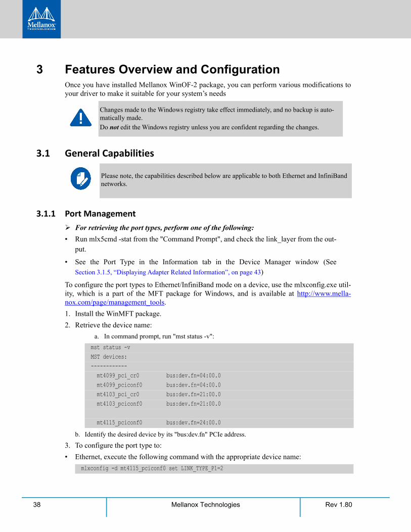
1. Install the WinMFT package.
2. Retrieve the device name:
a. In command prompt, run "mst status -v":
b. Identify the desired device by its "bus:dev.fn" PCIe address.
3. To configure the port type to:
• Ethernet, execute the following command with the appropriate device name:
Changes made to the Windows registry take effect immediately, and no backup is auto-matically made.
Do not edit the Windows registry unless you are confident regarding the changes.
Please note, the capabilities described below are applicable to both Ethernet and InfiniBand networks.
mst status -vMST devices:------------ mt4099_pci_cr0 bus:dev.fn=04:00.0 mt4099_pciconf0 bus:dev.fn=04:00.0 mt4103_pci_cr0 bus:dev.fn=21:00.0 mt4103_pciconf0 bus:dev.fn=21:00.0
mt4115_pciconf0 bus:dev.fn=24:00.0
mlxconfig -d mt4115_pciconf0 set LINK_TYPE_P1=2
Features Overview and Configuration
Rev 1.80 39Mellanox Technologies
• InfiniBand, execute the following command with the appropriate device name:
4. Reboot the system.
For further information, please refer to the MFT User Manual.
3.1.2 Assigning Port IP After InstallationBy default, your machine is configured to obtain an automatic IP address via a DHCP server. In some cases, the DHCP server may require the MAC address of the network adapter installed in your machine.
To obtain the MAC address:
Step 1. Open a CMD console-> Click Start-> Task Manager-> File-> Run new task-> and enter CMD.
Step 2. Display the MAC address as “Physical Address”
Configuring a static IP is the same for Ethernet adapters.
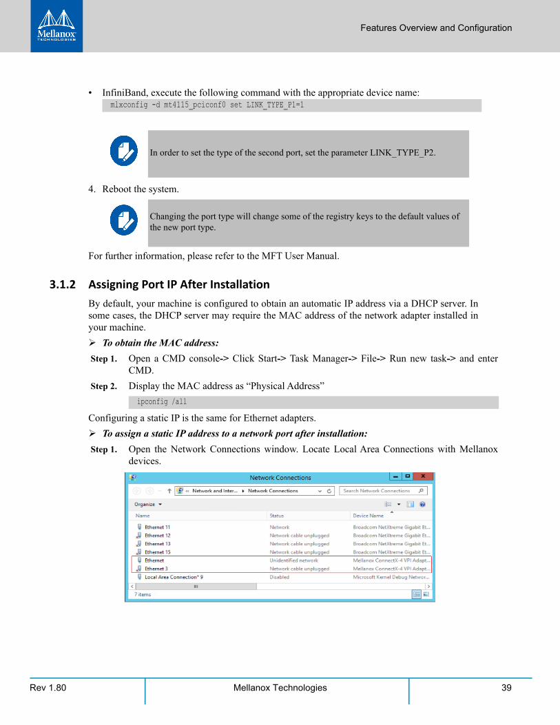
To assign a static IP address to a network port after installation:
Step 1. Open the Network Connections window. Locate Local Area Connections with Mellanox devices.
mlxconfig -d mt4115_pciconf0 set LINK_TYPE_P1=1
In order to set the type of the second port, set the parameter LINK_TYPE_P2.
Changing the port type will change some of the registry keys to the default values of the new port type.
ipconfig /all
Rev 1.8040 Mellanox Technologies
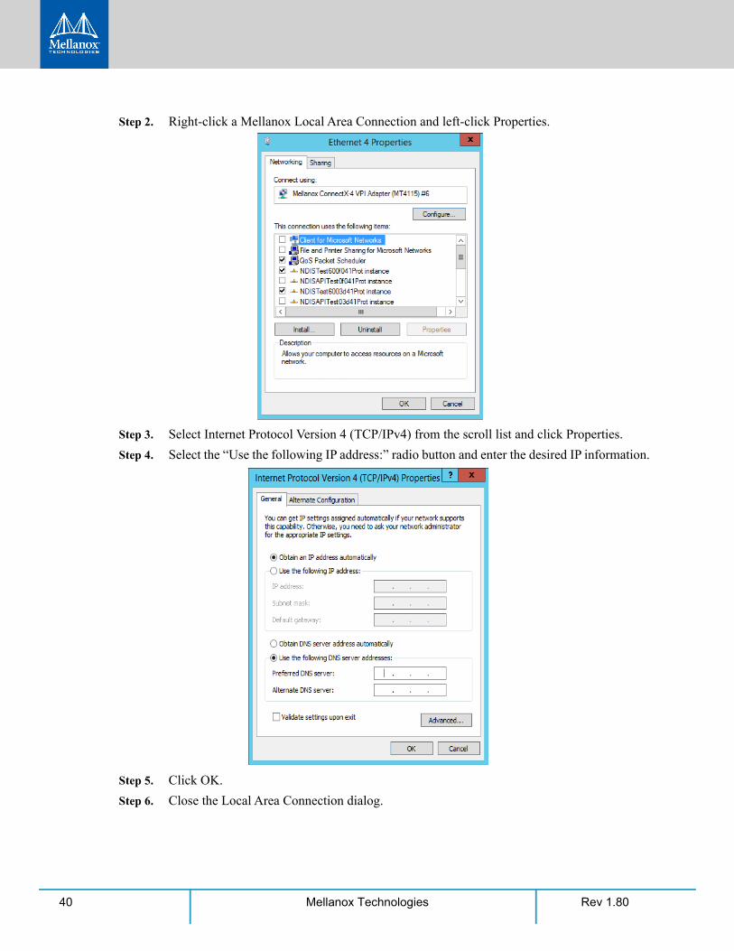
Step 2. Right-click a Mellanox Local Area Connection and left-click Properties.
Step 3. Select Internet Protocol Version 4 (TCP/IPv4) from the scroll list and click Properties.
Step 4. Select the “Use the following IP address:” radio button and enter the desired IP information.
Step 5. Click OK.
Step 6. Close the Local Area Connection dialog.
Features Overview and Configuration
Rev 1.80 41Mellanox Technologies
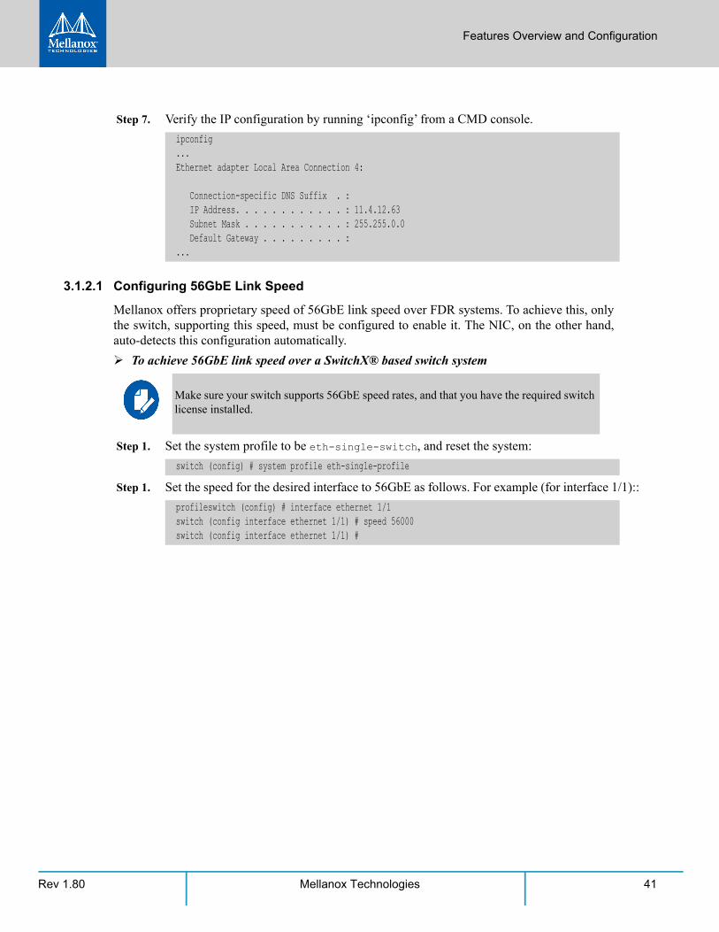
Step 7. Verify the IP configuration by running ‘ipconfig’ from a CMD console.
3.1.2.1 Configuring 56GbE Link Speed
Mellanox offers proprietary speed of 56GbE link speed over FDR systems. To achieve this, only the switch, supporting this speed, must be configured to enable it. The NIC, on the other hand, auto-detects this configuration automatically.
To achieve 56GbE link speed over a SwitchX® based switch system
Step 1. Set the system profile to be eth-single-switch, and reset the system:
Step 1. Set the speed for the desired interface to 56GbE as follows. For example (for interface 1/1)::
ipconfig...Ethernet adapter Local Area Connection 4:
Connection-specific DNS Suffix . : IP Address. . . . . . . . . . . . : 11.4.12.63 Subnet Mask . . . . . . . . . . . : 255.255.0.0 Default Gateway . . . . . . . . . :...
Make sure your switch supports 56GbE speed rates, and that you have the required switch license installed.
switch (config) # system profile eth-single-profile
profileswitch (config) # interface ethernet 1/1switch (config interface ethernet 1/1) # speed 56000switch (config interface ethernet 1/1) #
Rev 1.8042 Mellanox Technologies
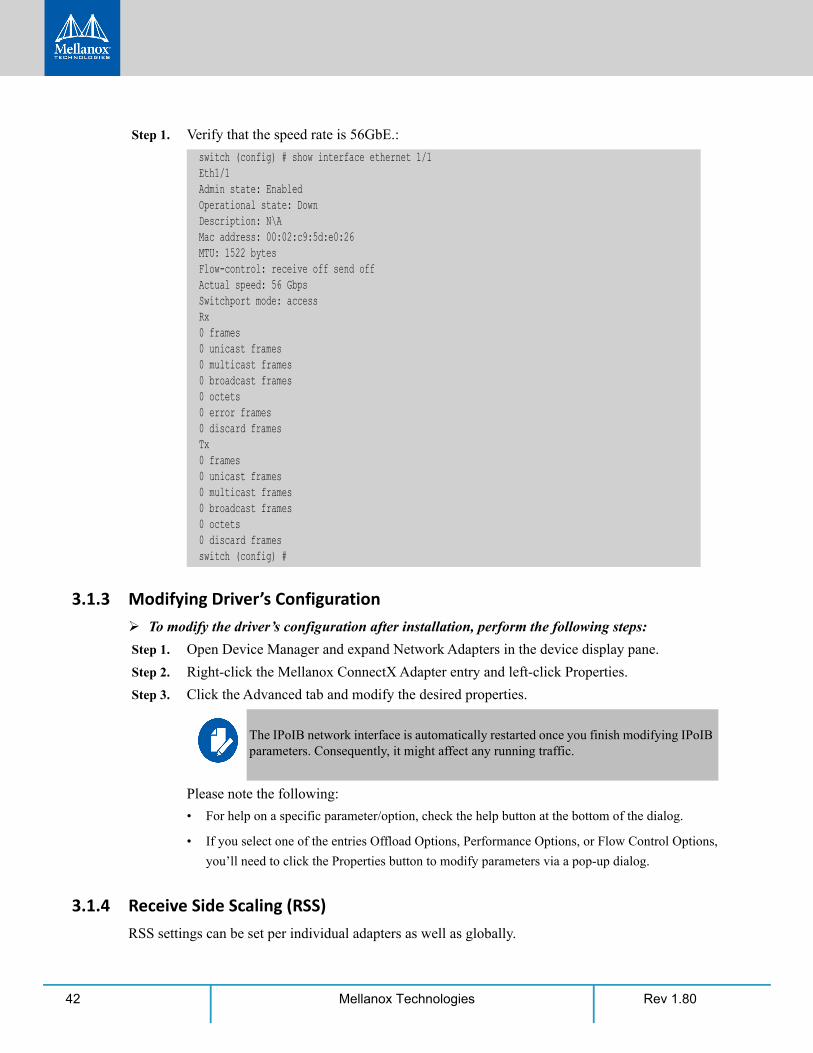
Step 1. Verify that the speed rate is 56GbE.:
3.1.3 Modifying Driver’s Configuration To modify the driver’s configuration after installation, perform the following steps:
Step 1. Open Device Manager and expand Network Adapters in the device display pane.
Step 2. Right-click the Mellanox ConnectX Adapter entry and left-click Properties.
Step 3. Click the Advanced tab and modify the desired properties.
Please note the following:
• For help on a specific parameter/option, check the help button at the bottom of the dialog.
• If you select one of the entries Offload Options, Performance Options, or Flow Control Options,
you’ll need to click the Properties button to modify parameters via a pop-up dialog.
3.1.4 Receive Side Scaling (RSS) RSS settings can be set per individual adapters as well as globally.
switch (config) # show interface ethernet 1/1Eth1/1Admin state: EnabledOperational state: DownDescription: N\AMac address: 00:02:c9:5d:e0:26MTU: 1522 bytesFlow-control: receive off send offActual speed: 56 GbpsSwitchport mode: accessRx0 frames0 unicast frames0 multicast frames0 broadcast frames0 octets0 error frames0 discard framesTx0 frames0 unicast frames0 multicast frames0 broadcast frames0 octets0 discard framesswitch (config) #
The IPoIB network interface is automatically restarted once you finish modifying IPoIB parameters. Consequently, it might affect any running traffic.
Features Overview and Configuration
Rev 1.80 43Mellanox Technologies
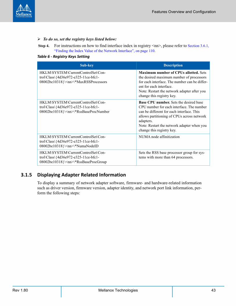
To do so, set the registry keys listed below:
Step 4. For instructions on how to find interface index in registry <nn>, please refer to Section 3.6.1, “Finding the Index Value of the Network Interface”, on page 110.
3.1.5 Displaying Adapter Related InformationTo display a summary of network adapter software, firmware- and hardware-related information such as driver version, firmware version, adapter identity, and network port link information, per-form the following steps:
Table 6 - Registry Keys Setting
Sub-key Description
HKLM\SYSTEM\CurrentControlSet\Con-trol\Class\{4d36e972-e325-11ce-bfc1-08002be10318}\<nn>\*MaxRSSProcessors
Maximum number of CPUs allotted. Sets the desired maximum number of processors for each interface. The number can be differ-ent for each interface. Note: Restart the network adapter after you change this registry key.
HKLM\SYSTEM\CurrentControlSet\Con-trol\Class\{4d36e972-e325-11ce-bfc1-08002be10318}\<nn>\*RssBaseProcNumber
Base CPU number. Sets the desired base CPU number for each interface. The number can be different for each interface. This allows partitioning of CPUs across network adapters. Note: Restart the network adapter when you change this registry key.
HKLM\SYSTEM\CurrentControlSet\Con-trol\Class\{4d36e972-e325-11ce-bfc1-08002be10318}\<nn>\*NumaNodeID
NUMA node affinitization
HKLM\SYSTEM\CurrentControlSet\Con-trol\Class\{4d36e972-e325-11ce-bfc1-08002be10318}\<nn>\*RssBaseProcGroup
Sets the RSS base processor group for sys-tems with more than 64 processors.

Rev 1.8044 Mellanox Technologies
Step 1. Display the Device Manager.
Step 2. Select the Information tab from the Properties sheet.
Features Overview and Configuration
Rev 1.80 45Mellanox Technologies
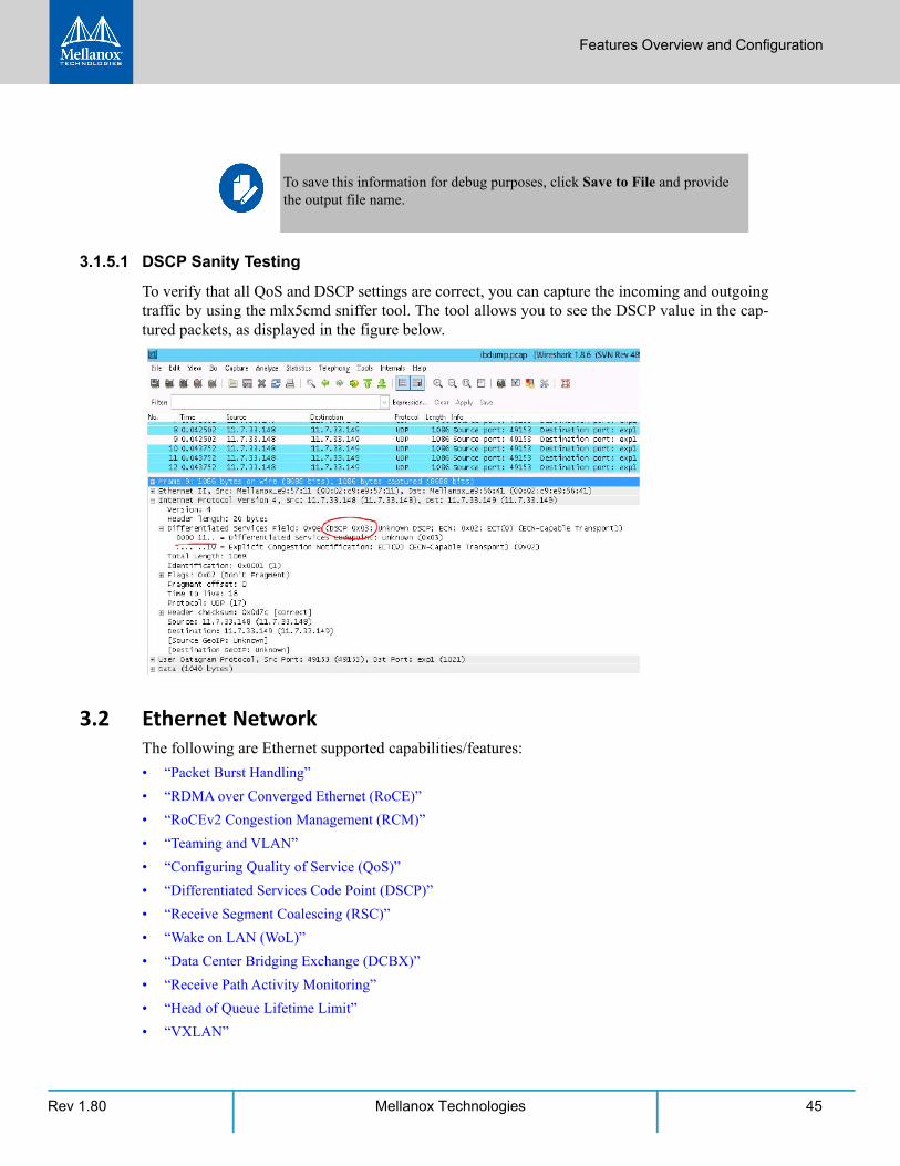
3.1.5.1 DSCP Sanity Testing
To verify that all QoS and DSCP settings are correct, you can capture the incoming and outgoing traffic by using the mlx5cmd sniffer tool. The tool allows you to see the DSCP value in the cap-tured packets, as displayed in the figure below.
3.2 Ethernet NetworkThe following are Ethernet supported capabilities/features:
• “Packet Burst Handling”
• “RDMA over Converged Ethernet (RoCE)”
• “RoCEv2 Congestion Management (RCM)”
• “Teaming and VLAN”
• “Configuring Quality of Service (QoS)”
• “Differentiated Services Code Point (DSCP)”
• “Receive Segment Coalescing (RSC)”
• “Wake on LAN (WoL)”
• “Data Center Bridging Exchange (DCBX)”
• “Receive Path Activity Monitoring”
• “Head of Queue Lifetime Limit”
• “VXLAN”
To save this information for debug purposes, click Save to File and provide the output file name.

Rev 1.8046 Mellanox Technologies
• “Threaded DPC”
3.2.1 Packet Burst HandlingThis feature allows packet burst handling, while avoiding packet drops that may occur when a large amount of packets is sent in a short period of time. For the feature’s registry keys, see 3.6.5 “Performance Registry Keys,” on page 114.
1. By default, the feature is disabled, and the AsyncRecieveIndicate registry key is set to 0. To enable the feature, choose one of the following options:
a.To enable packet burst buffering using threaded DPC (recommended), set the AsyncRecieveIndicate registry key to 1.
b. To enable packet burst buffering using polling, set the AsyncRecieveIndicate to 2.
2. To control the number of reserved receive packets, set the RfdReservationFactor registry key:
3.2.2 RDMA over Converged Ethernet (RoCE)Remote Direct Memory Access (RDMA) is the remote memory management capability that allows server to server data movement directly between application memory without any CPU involvement. RDMA over Converged Ethernet (RoCE) is a mechanism to provide this efficient data transfer with very low latencies on loss-less Ethernet networks. With advances in data center convergence over reliable Ethernet, ConnectX® EN with RoCE uses the proven and efficient RDMA transport to provide the platform for deploying RDMA technology in mainstream data center application at 10GigE and 40GigE link-speed. ConnectX® EN with its hardware offload support takes advantage of this efficient RDMA transport (InfiniBand) services over Ethernet to deliver ultra-low latency for performance-critical and transaction intensive applications such as financial, database, storage, and content delivery networks. RoCE encapsulates IB transport and GRH headers in Ethernet packets bearing a dedicated ether type. While the use of GRH is optional within InfiniBand subnets, it is mandatory when using RoCE. Applications written over IB verbs should work seamlessly, but they require provisioning of GRH information when creat-ing address vectors. The library and driver are modified to provide mapping from GID to MAC addresses required by the hardware.
3.2.2.1 IP Routable (RoCEv2)
RoCE has two addressing modes: MAC based GIDs, and IP address based GIDs. In RoCE IP based, if the IP address changes while the system is running, the GID for the port will automati-cally be updated with the new IP address, using either IPv4 or IPv6.
Default 150
Recommended 10,000
Maximum 5,000,000
The memory consumption will increase in accordance with the "RfdReservationFac-tor" registry key value.
Features Overview and Configuration
Rev 1.80 47Mellanox Technologies
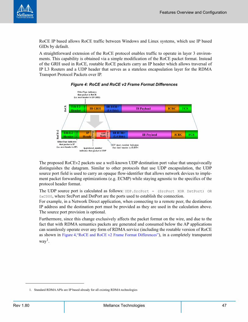
RoCE IP based allows RoCE traffic between Windows and Linux systems, which use IP based GIDs by default.
A straightforward extension of the RoCE protocol enables traffic to operate in layer 3 environ-ments. This capability is obtained via a simple modification of the RoCE packet format. Instead of the GRH used in RoCE, routable RoCE packets carry an IP header which allows traversal of IP L3 Routers and a UDP header that serves as a stateless encapsulation layer for the RDMA Transport Protocol Packets over IP.
Figure 4: RoCE and RoCE v2 Frame Format Differences
The proposed RoCEv2 packets use a well-known UDP destination port value that unequivocally distinguishes the datagram. Similar to other protocols that use UDP encapsulation, the UDP source port field is used to carry an opaque flow-identifier that allows network devices to imple-ment packet forwarding optimizations (e.g. ECMP) while staying agnostic to the specifics of the protocol header format.
The UDP source port is calculated as follows: UDP.SrcPort = (SrcPort XOR DstPort) OR 0xC000, where SrcPort and DstPort are the ports used to establish the connection. For example, in a Network Direct application, when connecting to a remote peer, the destination IP address and the destination port must be provided as they are used in the calculation above. The source port provision is optional.
Furthermore, since this change exclusively affects the packet format on the wire, and due to the fact that with RDMA semantics packets are generated and consumed below the AP applications can seamlessly operate over any form of RDMA service (including the routable version of RoCE as shown in Figure 4,“RoCE and RoCE v2 Frame Format Differences”), in a completely transparent
way1.
1. Standard RDMA APIs are IP based already for all existing RDMA technologies
Rev 1.8048 Mellanox Technologies
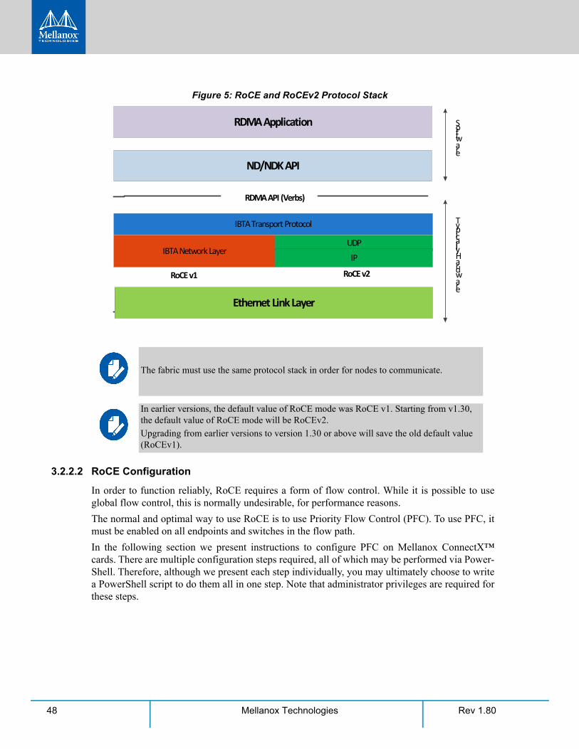
Figure 5: RoCE and RoCEv2 Protocol Stack
3.2.2.2 RoCE Configuration
In order to function reliably, RoCE requires a form of flow control. While it is possible to use global flow control, this is normally undesirable, for performance reasons.
The normal and optimal way to use RoCE is to use Priority Flow Control (PFC). To use PFC, it must be enabled on all endpoints and switches in the flow path.
In the following section we present instructions to configure PFC on Mellanox ConnectX™ cards. There are multiple configuration steps required, all of which may be performed via Power-Shell. Therefore, although we present each step individually, you may ultimately choose to write a PowerShell script to do them all in one step. Note that administrator privileges are required for these steps.
The fabric must use the same protocol stack in order for nodes to communicate.
In earlier versions, the default value of RoCE mode was RoCE v1. Starting from v1.30, the default value of RoCE mode will be RoCEv2.
Upgrading from earlier versions to version 1.30 or above will save the old default value (RoCEv1).
RDMA Application
ND/NDK API
IBTA Transport Protocol
IBTA Network Layer
RoCE v1 RoCE v2
RDMA API (Verbs)
Software
Typically Hardware
Ethernet Link Layer
UDPIP
Features Overview and Configuration
Rev 1.80 49Mellanox Technologies
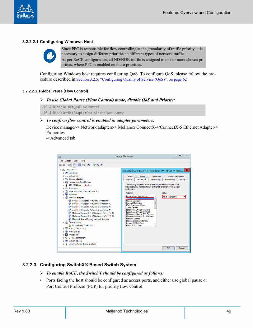
3.2.2.2.1 Configuring Windows Host
Configuring Windows host requires configuring QoS. To configure QoS, please follow the pro-cedure described in Section 3.2.5, “Configuring Quality of Service (QoS)”, on page 62
3.2.2.2.1.1Global Pause (Flow Control)
To use Global Pause (Flow Control) mode, disable QoS and Priority:
To confirm flow control is enabled in adapter parameters:
Device manager-> Network adapters-> Mellanox ConnectX-4/ConnectX-5 Ethernet Adapter-> Properties ->Advanced tab
3.2.2.3 Configuring SwitchX® Based Switch System
To enable RoCE, the SwitchX should be configured as follows:
• Ports facing the host should be configured as access ports, and either use global pause or Port Control Protocol (PCP) for priority flow control
Since PFC is responsible for flow controlling at the granularity of traffic priority, it is necessary to assign different priorities to different types of network traffic.
As per RoCE configuration, all ND/NDK traffic is assigned to one or more chosen pri-orities, where PFC is enabled on those priorities.
PS $ Disable-NetQosFlowControlPS $ Disable-NetAdapterQos <interface name>
Rev 1.8050 Mellanox Technologies
• Ports facing the network should be configured as trunk ports, and use Port Control Proto-col (PCP) for priority flow control
For further information on how to configure SwitchX, please refer to SwitchX User Manual.
3.2.2.4 Configuring Arista Switch
Step 1. Set the ports that face the hosts as trunk.
Step 2. Set VID allowed on trunk port to match the host VID.
Step 3. Set the ports that face the network as trunk.
Step 4. Assign the relevant ports to LAG.
Step 5. Enable PFC on ports that face the network.
3.2.2.4.1 Using Global Pause (Flow Control)
To enable Global Pause on ports that face the hosts, perform the following:
3.2.2.4.2 Using Priority Flow Control (PFC)
To enable Global Pause on ports that face the hosts, perform the following:
(config)# interface et10(config-if-Et10)# switchport mode trunk
(config-if-Et10)# switchport trunk allowed vlan 100
(config)# interface et20(config-if-Et20)# switchport mode trunk
(config)# interface et10(config-if-Et10)# dcbx mode ieee(config-if-Et10)# speed forced 40gfull(config-if-Et10)# channel-group 11 mode active
(config)# interface et20(config-if-Et20)# load-interval 5(config-if-Et20)# speed forced 40gfull (config-if-Et20)# switchport trunk native vlan tag(config-if-Et20)# switchport trunk allowed vlan 11(config-if-Et20)# switchport mode trunk(config-if-Et20)# dcbx mode ieee(config-if-Et20)# priority-flow-control mode on(config-if-Et20)# priority-flow-control priority 3 no-drop
(config)# interface et10(config-if-Et10)# flowcontrol receive on(config-if-Et10)# flowcontrol send on
(config)# interface et10(config-if-Et10)# dcbx mode ieee
Features Overview and Configuration
Rev 1.80 51Mellanox Technologies
3.2.2.5 Configuring Router (PFC only)
The router uses L3's DSCP value to mark the egress traffic of L2 PCP. The required mapping, maps the three most significant bits of the DSCP into the PCP. This is the default behavior, and no additional configuration is required.
3.2.2.5.1 Copying Port Control Protocol (PCP) between Subnets
The captured PCP option from the Ethernet header of the incoming packet can be used to set the PCP bits on the outgoing Ethernet header.
3.2.2.6 Configuring the RoCE Mode
Configuring the RoCE mode requires the following:
• RoCE mode is configured per adapter or per driver. If RoCE mode key is set for the adapter then it will be used. Otherwise, it will be configured by the per-driver key. The per-driver key is shared between all devices in the system.
• To update it for a specific adapter using the registry key, set the roce_mode as follows:
Step 1. Find the registry key index value of the adapter according to Section 3.6.1, “Finding the Index Value of the Network Interface”, on page 110.
Step 2. Set the roce_mode in the following path:
• To update it for all the devices using the registry key, set the roce_mode as follows:
(config-if-Et10)# priority-flow-control mode on(config-if-Et10)# priority-flow-control priority 3 no-drop
The supported RoCE modes depend on the firmware installed. If the firmware does not sup-port the needed mode, the fallback mode would be the maximum supported RoCE mode of the installed NIC.
RoCE is enabled by default. Configuring or disabling the RoCE mode can be done via the registry key.
HKEY_LOCAL_MACHINE\SYSTEM\CurrentControlSet\Control\Class\{4d36e972-e325-11ce-bfc1-08002be10318}\<IndexValue>
HKEY_LOCAL_MACHINE\SYSTEM\CurrentControlSet\Services\mlx5\Parameters\Roce
For changes to take effect, please restart the network adapter after changing this registry key.
Rev 1.8052 Mellanox Technologies
3.2.2.6.1 Registry Key Parameters
The following are per-driver and will apply to all available adapters.
3.2.3 RoCEv2 Congestion Management (RCM)Network Congestion occurs when the number of packets being transmitted through the network approaches the packet handling the capacity of the network. A congested network will suffer from throughput deterioration manifested by increasing time delays and high latency.
In lossy environments, this leads to a packet loss. In lossless environments, it leads to “victim flows” (streams of data which are affected by the congestion, caused by other data flows that pass through the same network).
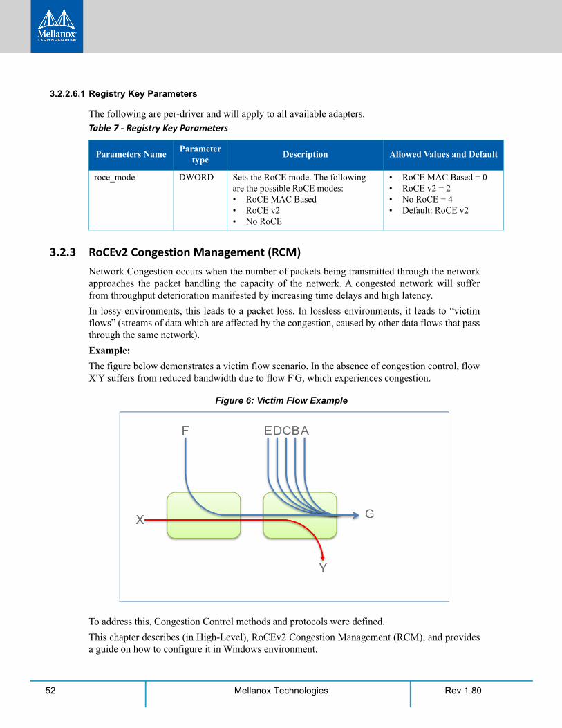
Example:
The figure below demonstrates a victim flow scenario. In the absence of congestion control, flow X'Y suffers from reduced bandwidth due to flow F'G, which experiences congestion.
Figure 6: Victim Flow Example
To address this, Congestion Control methods and protocols were defined.
This chapter describes (in High-Level), RoCEv2 Congestion Management (RCM), and provides a guide on how to configure it in Windows environment.
Table 7 - Registry Key Parameters
Parameters NameParameter
typeDescription Allowed Values and Default
roce_mode DWORD Sets the RoCE mode. The following are the possible RoCE modes:• RoCE MAC Based• RoCE v2• No RoCE
• RoCE MAC Based = 0• RoCE v2 = 2• No RoCE = 4• Default: RoCE v2
Features Overview and Configuration
Rev 1.80 53Mellanox Technologies
RoCEv2 Congestion Management (RCM) provides the capability to avoid congestion hot spots and optimize the throughput of the fabric.
With RCM, congestion in the fabric is reported back to the “sources” of traffic. The sources, in turn, react by throttling down their injection rates, thus preventing the negative effects of fabric buffer saturation and increased queuing delays.
For signaling of congestion, RCM relies on the mechanism defined in RFC3168, also known as DCQCN.
The source node and destination node can be considered as a “closed-loop control” system. Start-ing from the trigger, when the destination node reflects the congestion alert to the source node, the source node reacts by decreasing, and later on increasing, the Tx rates according to the feed-back provided. The source node keeps increasing the Tx rates until the system reaches a steady state of non-congested flow with traffic as high rate as possible.
The RoCEv2 Congestion Management feature is composed of three points:
• The congestion point (CP) - detects congestion and marks packets using the DCQCN bits
• The notification point (NP) (receiving end node) - reacts to the DCQCN marked packets by sending congestion notification packets (CNPs)
• The reaction point (RP) (transmitting end node) - reduces the transmission rate accord-ing to the received CNPs
These three components can be seen in the High-Level sequence diagram below:
Figure 7: High-Level Sequence Diagram

Rev 1.8054 Mellanox Technologies
For further details, please refer to the IBTA RoCeV2 Spec, Annex A-17.
3.2.3.1 Restrictions and Limitations
General:
• In order for RCM to function properly, the elements in the communication path must support and be configured for RCM (nodes) and DCQCN marking (Switches, Routers).
• ConnectX®-4 and ConnectX®-4 Lx support congestion control only with RoCEv2.
• RCM does not remove/replace the need for flow control. In order for RoCEv2 to work properly, flow control must be configured. It is not recommended to configure RCM without PFC or global pauses.
Mellanox:
• SW Versions
• Minimal firmware version - 2.30
• Minimal driver version - 1.35
• Mellanox switch support starting from “Spectrum”
• RCM is supported only with physical adapter
3.2.3.2 RCM Configuration
RCM configuration to Mellanox adapter is done via Mlx5Cmd tool.
• In order to view the current status of RCM on the adapter, run the following command:
Mlx5Cmd.exe -Qosconfig -Dcqcn -Name <Network Adapter Name> -Get
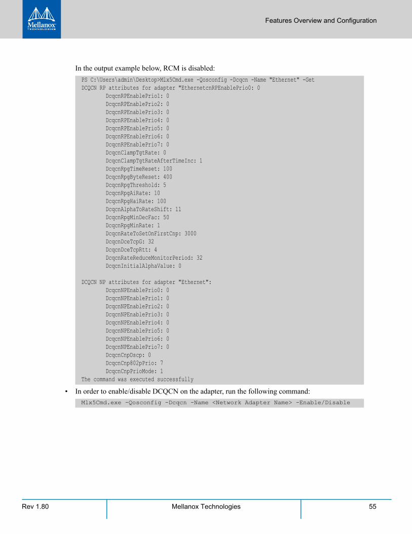
Features Overview and Configuration
Rev 1.80 55Mellanox Technologies
In the output example below, RCM is disabled:
• In order to enable/disable DCQCN on the adapter, run the following command:
PS C:\Users\admin\Desktop>Mlx5Cmd.exe -Qosconfig -Dcqcn -Name "Ethernet" -GetDCQCN RP attributes for adapter "EthernetcnRPEnablePrio0: 0 DcqcnRPEnablePrio1: 0 DcqcnRPEnablePrio2: 0 DcqcnRPEnablePrio3: 0 DcqcnRPEnablePrio4: 0 DcqcnRPEnablePrio5: 0 DcqcnRPEnablePrio6: 0 DcqcnRPEnablePrio7: 0 DcqcnClampTgtRate: 0 DcqcnClampTgtRateAfterTimeInc: 1 DcqcnRpgTimeReset: 100 DcqcnRpgByteReset: 400 DcqcnRpgThreshold: 5 DcqcnRpgAiRate: 10 DcqcnRpgHaiRate: 100 DcqcnAlphaToRateShift: 11 DcqcnRpgMinDecFac: 50 DcqcnRpgMinRate: 1 DcqcnRateToSetOnFirstCnp: 3000 DcqcnDceTcpG: 32 DcqcnDceTcpRtt: 4 DcqcnRateReduceMonitorPeriod: 32 DcqcnInitialAlphaValue: 0
DCQCN NP attributes for adapter "Ethernet": DcqcnNPEnablePrio0: 0 DcqcnNPEnablePrio1: 0 DcqcnNPEnablePrio2: 0 DcqcnNPEnablePrio3: 0 DcqcnNPEnablePrio4: 0 DcqcnNPEnablePrio5: 0 DcqcnNPEnablePrio6: 0 DcqcnNPEnablePrio7: 0 DcqcnCnpDscp: 0 DcqcnCnp802pPrio: 7 DcqcnCnpPrioMode: 1The command was executed successfully
Mlx5Cmd.exe -Qosconfig -Dcqcn -Name <Network Adapter Name> -Enable/Disable
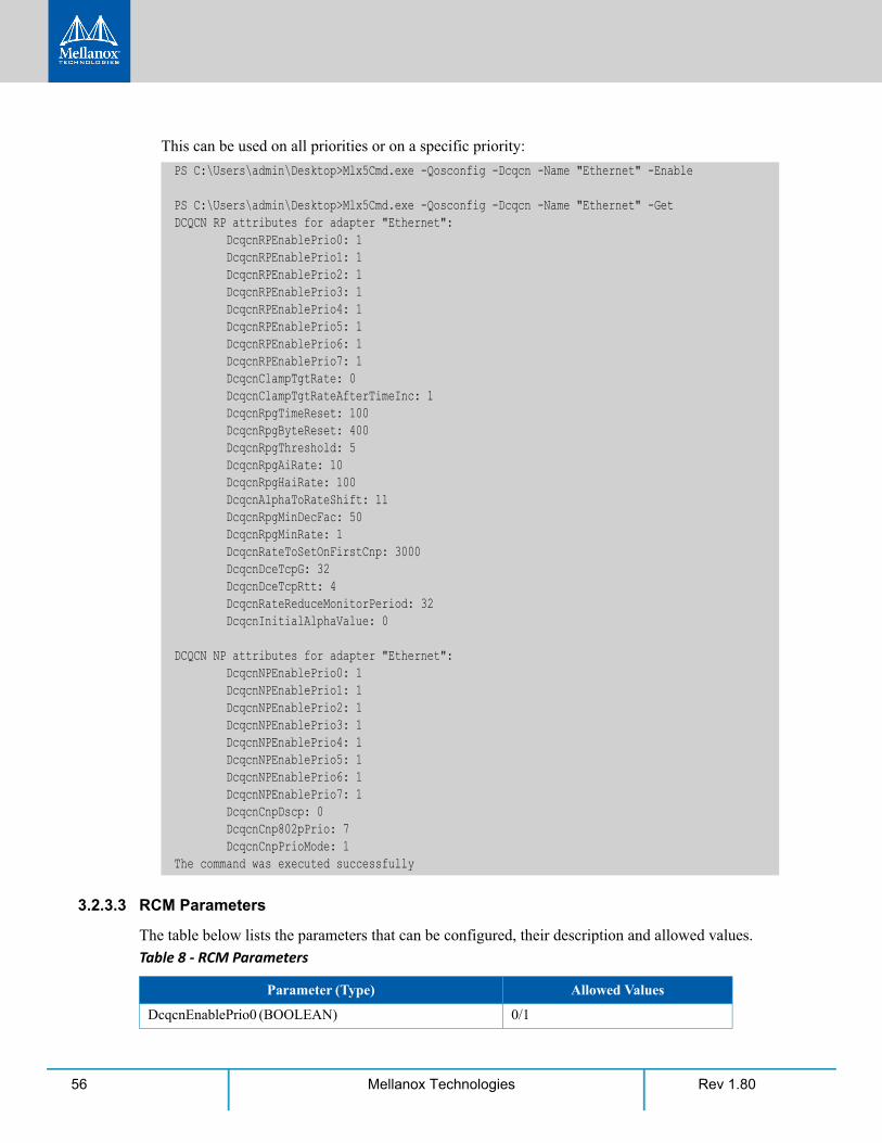
Rev 1.8056 Mellanox Technologies
This can be used on all priorities or on a specific priority:
3.2.3.3 RCM Parameters
The table below lists the parameters that can be configured, their description and allowed values.
PS C:\Users\admin\Desktop>Mlx5Cmd.exe -Qosconfig -Dcqcn -Name "Ethernet" -Enable
PS C:\Users\admin\Desktop>Mlx5Cmd.exe -Qosconfig -Dcqcn -Name "Ethernet" -GetDCQCN RP attributes for adapter "Ethernet": DcqcnRPEnablePrio0: 1 DcqcnRPEnablePrio1: 1 DcqcnRPEnablePrio2: 1 DcqcnRPEnablePrio3: 1 DcqcnRPEnablePrio4: 1 DcqcnRPEnablePrio5: 1 DcqcnRPEnablePrio6: 1 DcqcnRPEnablePrio7: 1 DcqcnClampTgtRate: 0 DcqcnClampTgtRateAfterTimeInc: 1 DcqcnRpgTimeReset: 100 DcqcnRpgByteReset: 400 DcqcnRpgThreshold: 5 DcqcnRpgAiRate: 10 DcqcnRpgHaiRate: 100 DcqcnAlphaToRateShift: 11 DcqcnRpgMinDecFac: 50 DcqcnRpgMinRate: 1 DcqcnRateToSetOnFirstCnp: 3000 DcqcnDceTcpG: 32 DcqcnDceTcpRtt: 4 DcqcnRateReduceMonitorPeriod: 32 DcqcnInitialAlphaValue: 0
DCQCN NP attributes for adapter "Ethernet": DcqcnNPEnablePrio0: 1 DcqcnNPEnablePrio1: 1 DcqcnNPEnablePrio2: 1 DcqcnNPEnablePrio3: 1 DcqcnNPEnablePrio4: 1 DcqcnNPEnablePrio5: 1 DcqcnNPEnablePrio6: 1 DcqcnNPEnablePrio7: 1 DcqcnCnpDscp: 0 DcqcnCnp802pPrio: 7 DcqcnCnpPrioMode: 1The command was executed successfully
Table 8 - RCM Parameters
Parameter (Type) Allowed Values
DcqcnEnablePrio0 (BOOLEAN) 0/1
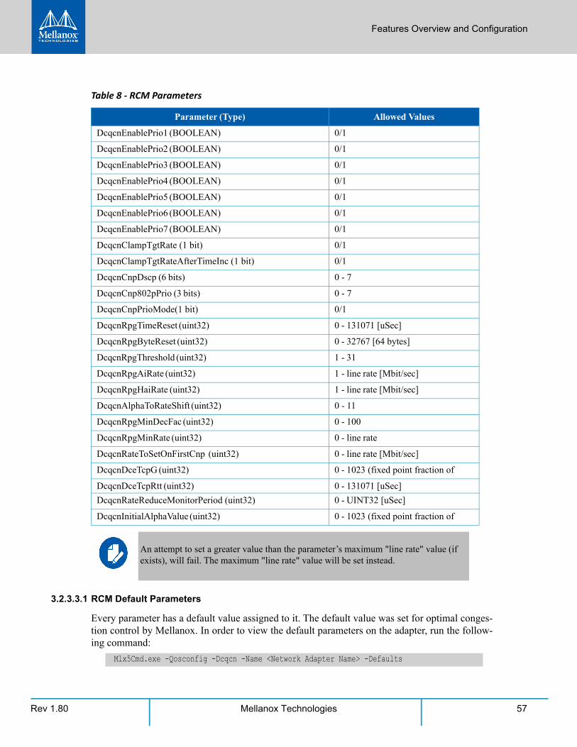
Features Overview and Configuration
Rev 1.80 57Mellanox Technologies
3.2.3.3.1 RCM Default Parameters
Every parameter has a default value assigned to it. The default value was set for optimal conges-tion control by Mellanox. In order to view the default parameters on the adapter, run the follow-ing command:
DcqcnEnablePrio1 (BOOLEAN) 0/1
DcqcnEnablePrio2 (BOOLEAN) 0/1
DcqcnEnablePrio3 (BOOLEAN) 0/1
DcqcnEnablePrio4 (BOOLEAN) 0/1
DcqcnEnablePrio5 (BOOLEAN) 0/1
DcqcnEnablePrio6 (BOOLEAN) 0/1
DcqcnEnablePrio7 (BOOLEAN) 0/1
DcqcnClampTgtRate (1 bit) 0/1
DcqcnClampTgtRateAfterTimeInc (1 bit) 0/1
DcqcnCnpDscp (6 bits) 0 - 7
DcqcnCnp802pPrio (3 bits) 0 - 7
DcqcnCnpPrioMode(1 bit) 0/1
DcqcnRpgTimeReset (uint32) 0 - 131071 [uSec]
DcqcnRpgByteReset (uint32) 0 - 32767 [64 bytes]
DcqcnRpgThreshold (uint32) 1 - 31
DcqcnRpgAiRate (uint32) 1 - line rate [Mbit/sec]
DcqcnRpgHaiRate (uint32) 1 - line rate [Mbit/sec]
DcqcnAlphaToRateShift (uint32) 0 - 11
DcqcnRpgMinDecFac (uint32) 0 - 100
DcqcnRpgMinRate (uint32) 0 - line rate
DcqcnRateToSetOnFirstCnp (uint32) 0 - line rate [Mbit/sec]
DcqcnDceTcpG (uint32) 0 - 1023 (fixed point fraction of
DcqcnDceTcpRtt (uint32) 0 - 131071 [uSec]
DcqcnRateReduceMonitorPeriod (uint32) 0 - UINT32 [uSec]
DcqcnInitialAlphaValue (uint32) 0 - 1023 (fixed point fraction of
An attempt to set a greater value than the parameter’s maximum "line rate" value (if exists), will fail. The maximum "line rate" value will be set instead.
Mlx5Cmd.exe -Qosconfig -Dcqcn -Name <Network Adapter Name> -Defaults
Table 8 - RCM Parameters
Parameter (Type) Allowed Values
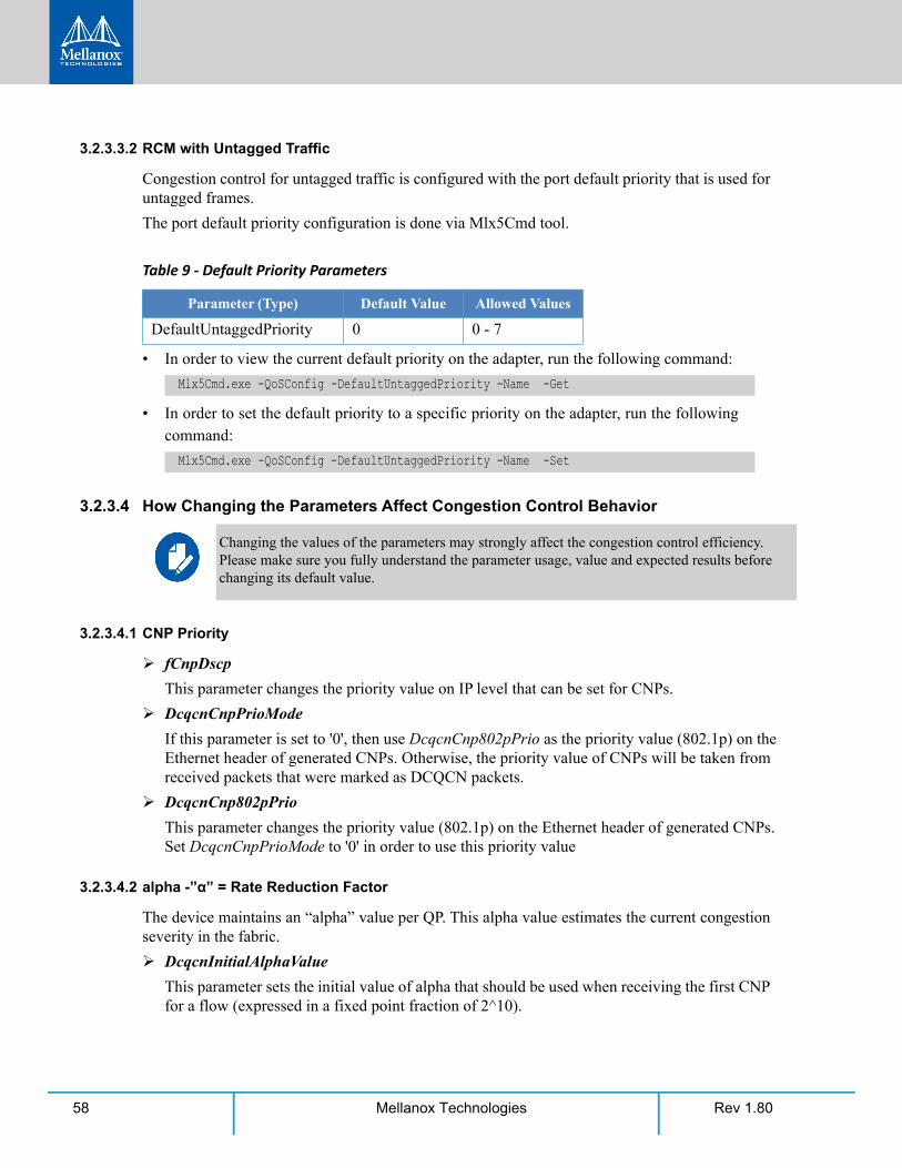
Rev 1.8058 Mellanox Technologies
3.2.3.3.2 RCM with Untagged Traffic
Congestion control for untagged traffic is configured with the port default priority that is used for untagged frames.
The port default priority configuration is done via Mlx5Cmd tool.
• In order to view the current default priority on the adapter, run the following command:
• In order to set the default priority to a specific priority on the adapter, run the following command:
3.2.3.4 How Changing the Parameters Affect Congestion Control Behavior
3.2.3.4.1 CNP Priority
fCnpDscp
This parameter changes the priority value on IP level that can be set for CNPs.
DcqcnCnpPrioMode
If this parameter is set to '0', then use DcqcnCnp802pPrio as the priority value (802.1p) on the Ethernet header of generated CNPs. Otherwise, the priority value of CNPs will be taken from received packets that were marked as DCQCN packets.
DcqcnCnp802pPrio
This parameter changes the priority value (802.1p) on the Ethernet header of generated CNPs. Set DcqcnCnpPrioMode to '0' in order to use this priority value
3.2.3.4.2 alpha -”α” = Rate Reduction Factor
The device maintains an “alpha” value per QP. This alpha value estimates the current congestion severity in the fabric.
DcqcnInitialAlphaValue
This parameter sets the initial value of alpha that should be used when receiving the first CNP for a flow (expressed in a fixed point fraction of 2^10).
Table 9 - Default Priority Parameters
Parameter (Type) Default Value Allowed Values
DefaultUntaggedPriority 0 0 - 7
Mlx5Cmd.exe -QoSConfig -DefaultUntaggedPriority -Name -Get
Mlx5Cmd.exe -QoSConfig -DefaultUntaggedPriority -Name -Set
Changing the values of the parameters may strongly affect the congestion control efficiency. Please make sure you fully understand the parameter usage, value and expected results before changing its default value.
Features Overview and Configuration
Rev 1.80 59Mellanox Technologies
The value of alpha is updated once every DcqcnDceTcpRtt, regardless of the reception of a CNP. If a CNP is received during this time frame, alpha value will increase. If no CNP recep-tion happens, alpha value will decrease.
DcqcnDceTcpG and DcqcnDceTcpRtt
These two parameters maintain alpha.
• If a CNP is received on the RP - alpha is increased: (1-DcqcnDecTcpG)*α + DcqcnDecTcpG
• If no CNP is received for a duration of DcqcnDceTcpRtt microseconds, alpha is decreased: (1- DcqcnDecTcpG) * alpha
3.2.3.4.3 Decrease (on the “RP”)
Changing the DcqcnRateToSetOnFirstCnp parameter determines the current rate (cr) that will be set once the first CNP is received.
The rate is updated only once every DcqcnRateReduceMonitorPeriod microseconds (multiple CNPs received during this time frame will not affect the rate) by using the following two formu-las:
• Cr1(new) = (1- (α /(2^DcqcnAlphaToRateShift)) )*Cr(old)
• Cr2(new) = Cr(old)/DcqcnRpgMinDecFac
The maximal reduced rate will be chosen from these two formulas.
The target rate will be updated to the previous current rate according to Section 3.2.3.4.4, “Increase (on the “RP”)” below.
DcqcnRpgMinDecFac
This parameter defines the maximal ratio of decrease in a single step (Denominator: !zero. Please see formula above).
DcqcnAlphaToRateShift
This parameter defines the decrement rate for a given alpha (see formula above)
DcqcnRpgMinRate
In addition to the DcqcnRpgMinDecFac, the DcqcnRpgMinRate parameter defines the minimal rate value for the entire single flow.
Note: Setting it to a line rate will disable the congestion control.
3.2.3.4.4 Increase (on the “RP”)
RP increases its sending rate using a timer and a byte counter. The byte counter increases rate for every DcqcnRpgByteResetx64 bytes (mark it as B), while the timer increases rate every Dcqcn-RpgTimeReset time units (mark it as T). Every successful increase due to bytes transmitted/time passing is counted in a variable called rpByteStage and rpTimeStage (respectively).
The DcqcnRpgThreshold parameter defines the number of successive increase iteration (mark it as Th).
Rev 1.8060 Mellanox Technologies
The increase flow is divided into 3 types of phases, which are actually states in the “RP Rate Control State Machine”.
The transition between the steps is decided according to DcqcnRpgThreshold parameter.
• Fast Recovery If MAX (rpByteStage, rpTimeStage) < Th.
• No change to Tr
• Additive Increase If MAX (rpByteStage, rpTimeStage) > Th. && MIN (rpByteStage, rpTimeStage) < Th.
• DcqcnRpgAiRate value is used to increase Tr
• Hyper Additive Increase If MAX (rpByteStage, rpTimeStage) > Th. && MIN (rpByteStage, rpTimeStage) > Th.
• DcqcnRpgHaiRate value is used to increase Tr
For further details, please refer to 802.1Qau standard, sections 32.11-32.15.
DcqcnClampTgtRateAfterTimeInc
When receiving a CNP, the target rate should be updated if the transmission rate was increased due to the timer, and not only due to the byte counter.
DcqcnClampTgtRate
If set, whenever a CNP is processed, the target rate is updated to be the current rate.
3.2.3.5 Mellanox Commands and Examples
For a full description of Congestion Control commands please refer to Mellanox WinOF-2 User Manual section MlxCmd Utilities.
1. Set a value for one or more parameters:
Mlx5Cmd.exe -Qosconfig -Dcqcn -Name <Network Adapter Name> -Set -Arg1 <value> -Arg2 <value>
Example:
2. Enable/Disable DCQCN for a specific priority:
Mlx5Cmd.exe -Qosconfig -Dcqcn -Name <Network Adapter Name> -Enable <prio>
Example:
3. Enable/Disable DCQCN for all priorities:
Mlx5Cmd.exe -Qosconfig -Dcqcn -Name <Network Adapter Name> -Enable
Example:
4. Set port default priority for a specific priority:
PS C:\Users\admin\Desktop>Mlx5Cmd.exe -Qosconfig -Dcqcn -Name "Ethernet" -Set -DcqcnClampTg-tRate 1 -DcqcnCnpDscp 3
PS C:\Users\admin\Desktop>Mlx5Cmd.exe -Qosconfig -Dcqcn -Name "Ethernet" -Enable/Disable 3
PS C:\Users\admin\Desktop>Mlx5Cmd.exe -Qosconfig -Dcqcn -Name "Ethernet" -Enable/Disable
Features Overview and Configuration
Rev 1.80 61Mellanox Technologies
Mlx5Cmd.exe -DefaultUntaggedPriority -Name <Network Adapter Name> -Set <prio>
Example:
5. Restore the default settings of DCQCN the are defined by Mellanox:
Mlx5Cmd.exe -Dcqcn -Name <Network Adapter Name> -Restore
Example:
3.2.4 Teaming and VLANWindows Server 2012 and above supports Teaming as part of the operating system. Please refer to Microsoft guide “NIC Teaming in Windows Server 2012” following the link below:
http://www.microsoft.com/en-us/download/confirmation.aspx?id=40319
Note that the Microsoft teaming mechanism is only available on Windows Server distributions.
3.2.4.1 Configuring a Network to Work with VLAN in Windows Server 2012 and Above
To configure a port to work with VLAN using the Device Manager.
Step 1. Open the Device Manager.
Step 2. Go to the Network adapters.
Step 3. Go to the properties of Mellanox ConnectX®-4 Ethernet Adapter card.
Step 4. Go to the Advanced tab.
Step 5. Choose the VLAN ID in the Property window.
PS C:\Users\admin\Desktop>Mlx5Cmd.exe -DefaultUntaggedPriority -Name "Ethernet" -Set 3
PS C:\Users\admin\Desktop>Mlx5Cmd.exe -Dcqcn -Name "Ethernet" -Restore
For information on the RCM counters, please refer to Section 3.9.5, “Mellanox WinOF-2 Conges-tion Control”, on page 133.
In this procedure you DO NOT create a VLAN, rather use an existing VLAN ID.
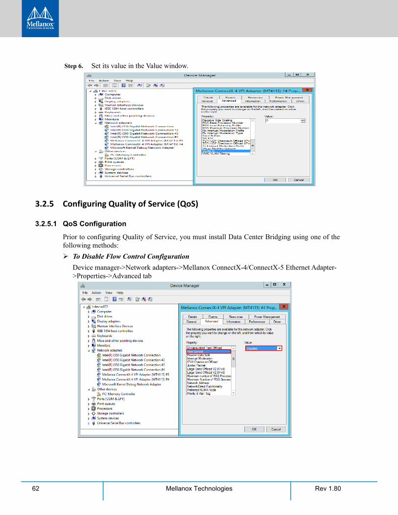
Rev 1.8062 Mellanox Technologies
Step 6. Set its value in the Value window.
3.2.5 Configuring Quality of Service (QoS)
3.2.5.1 QoS Configuration
Prior to configuring Quality of Service, you must install Data Center Bridging using one of the following methods:
To Disable Flow Control Configuration
Device manager->Network adapters->Mellanox ConnectX-4/ConnectX-5 Ethernet Adapter->Properties->Advanced tab
Features Overview and Configuration
Rev 1.80 63Mellanox Technologies
To install the Data Center Bridging using the Server Manager:
Step 1. Open the 'Server Manager'.
Step 2. Select 'Add Roles and Features'.
Step 3. Click Next.
Step 4. Select 'Features' on the left panel.
Step 5. Check the 'Data Center Bridging' checkbox.
Step 6. Click 'Install'.
To install the Data Center Bridging using PowerShell:
Step 1. Enable Data Center Bridging (DCB).
To configure QoS on the host:
Step 1. Change the Windows PowerShell execution policy:
Step 2. Remove the entire previous QoS configuration:
Step 3. Create a Quality of Service (QoS) policy and tag each type of traffic with the relevant prior-ity.
In this example, TCP/UDP use priority 1, SMB over TCP use priority 3.
Step 4. Create a QoS policy for SMB over SMB Direct traffic on Network Direct port 445.
Step 5. [Optional] If VLANs are used, mark the egress traffic with the relevant VlanID. The NIC is referred as "Ethernet 4” in the examples below.
Step 6. [Optional] Configure the IP address for the NIC.
PS $ Install-WindowsFeature Data-Center-Bridging
The procedure below is not saved after you reboot your system. Hence, we recom-mend you create a script using the steps below and run it on the startup of the local machine. Please see the procedure below on how to add the script to the local machine startup scripts.
PS $ Set-ExecutionPolicy AllSigned
PS $ Remove-NetQosTrafficClassPS $ Remove-NetQosPolicy -Confirm:$False
PS $ New-NetQosPolicy "DEFAULT" -store Activestore -Default -PriorityValue8021Action 3PS $ New-NetQosPolicy "TCP" -store Activestore -IPProtocolMatchCondition TCP -Priority-Value8021Action 1PS $ New-NetQosPolicy "UDP" -store Activestore -IPProtocolMatchCondition UDP -Priority-Value8021Action 1New-NetQosPolicy “SMB” –SMB –PriorityValue8021Action 3
PS $ New-NetQosPolicy "SMBDirect" -store Activestore -NetDirectPortMatchCondition 445 -PriorityValue8021Action 3
PS $ Set-NetAdapterAdvancedProperty -Name "Ethernet 4" -RegistryKeyword "VlanID" -Reg-istryValue "55"
Rev 1.8064 Mellanox Technologies
If DHCP is used, the IP address will be assigned automatically.
Step 7. [Optional] Set the DNS server (assuming its IP address is 192.168.1.2).
Step 8. Disable Priority Flow Control (PFC) for all other priorities except for 3.
Step 9. Enable QoS on the relevant interface.
Step 10. Enable PFC on priority 3.
To add the script to the local machine startup scripts:
Step 1. From the PowerShell invoke.
Step 2. In the pop-up window, under the 'Computer Configuration' section, perform the following:
1. Select Windows Settings 2. Select Scripts (Startup/Shutdown) 3. Double click Startup to open the Startup Properties
PS $ Set-NetIPInterface -InterfaceAlias “Ethernet 4” -DHCP DisabledPS $ Remove-NetIPAddress -InterfaceAlias “Ethernet 4” -AddressFamily IPv4 -Con-firm:$falsePS $ New-NetIPAddress -InterfaceAlias “Ethernet 4” -IPAddress 192.168.1.10 -Prefix-Length 24 -Type Unicast
PS $ Set-DnsClientServerAddress -InterfaceAlias “Ethernet 4” -ServerAddresses 192.168.1.2
After establishing the priorities of ND/NDK traffic, the priorities must have PFC enabled on them.
PS $ Disable-NetQosFlowControl 0,1,2,4,5,6,7
PS $ Enable-NetAdapterQos -InterfaceAlias "Ethernet 4"
PS $ Enable-NetQosFlowControl -Priority 3
gpedit.msc
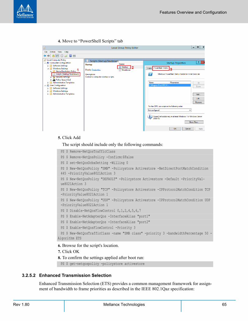
Features Overview and Configuration
Rev 1.80 65Mellanox Technologies
4. Move to “PowerShell Scripts” tab
5. Click Add
The script should include only the following commands:
6. Browse for the script's location. 7. Click OK 8. To confirm the settings applied after boot run:
3.2.5.2 Enhanced Transmission Selection
Enhanced Transmission Selection (ETS) provides a common management framework for assign-ment of bandwidth to frame priorities as described in the IEEE 802.1Qaz specification:
PS $ Remove-NetQosTrafficClassPS $ Remove-NetQosPolicy -Confirm:$FalsePS $ set-NetQosDcbxSetting -Willing 0PS $ New-NetQosPolicy "SMB" -Policystore Activestore -NetDirectPortMatchCondition 445 -PriorityValue8021Action 3PS $ New-NetQosPolicy "DEFAULT" -Policystore Activestore -Default -PriorityVal-ue8021Action 3PS $ New-NetQosPolicy "TCP" -Policystore Activestore -IPProtocolMatchCondition TCP -PriorityValue8021Action 1PS $ New-NetQosPolicy "UDP" -Policystore Activestore -IPProtocolMatchCondition UDP -PriorityValue8021Action 1PS $ Disable-NetQosFlowControl 0,1,2,4,5,6,7PS $ Enable-NetAdapterQos -InterfaceAlias "port1" PS $ Enable-NetAdapterQos -InterfaceAlias "port2"PS $ Enable-NetQosFlowControl -Priority 3PS $ New-NetQosTrafficClass -name "SMB class" -priority 3 -bandwidthPercentage 50 -
Algorithm ETS
PS $ get-netqospolicy -policystore activestore
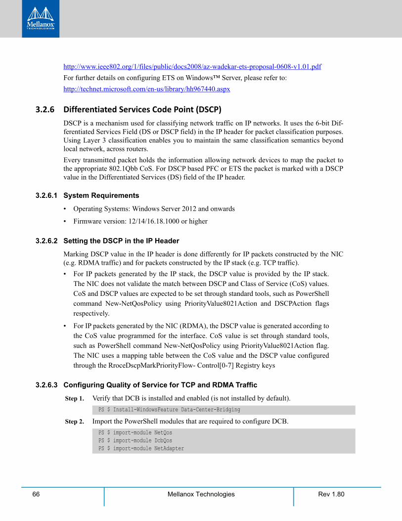
Rev 1.8066 Mellanox Technologies
http://www.ieee802.org/1/files/public/docs2008/az-wadekar-ets-proposal-0608-v1.01.pdf
For further details on configuring ETS on Windows™ Server, please refer to:
http://technet.microsoft.com/en-us/library/hh967440.aspx
3.2.6 Differentiated Services Code Point (DSCP)DSCP is a mechanism used for classifying network traffic on IP networks. It uses the 6-bit Dif-ferentiated Services Field (DS or DSCP field) in the IP header for packet classification purposes. Using Layer 3 classification enables you to maintain the same classification semantics beyond local network, across routers.
Every transmitted packet holds the information allowing network devices to map the packet to the appropriate 802.1Qbb CoS. For DSCP based PFC or ETS the packet is marked with a DSCP value in the Differentiated Services (DS) field of the IP header.
3.2.6.1 System Requirements
• Operating Systems: Windows Server 2012 and onwards
• Firmware version: 12/14/16.18.1000 or higher
3.2.6.2 Setting the DSCP in the IP Header
Marking DSCP value in the IP header is done differently for IP packets constructed by the NIC (e.g. RDMA traffic) and for packets constructed by the IP stack (e.g. TCP traffic).
• For IP packets generated by the IP stack, the DSCP value is provided by the IP stack. The NIC does not validate the match between DSCP and Class of Service (CoS) values. CoS and DSCP values are expected to be set through standard tools, such as PowerShell command New-NetQosPolicy using PriorityValue8021Action and DSCPAction flags respectively.
• For IP packets generated by the NIC (RDMA), the DSCP value is generated according to the CoS value programmed for the interface. CoS value is set through standard tools, such as PowerShell command New-NetQosPolicy using PriorityValue8021Action flag. The NIC uses a mapping table between the CoS value and the DSCP value configured through the RroceDscpMarkPriorityFlow- Control[0-7] Registry keys
3.2.6.3 Configuring Quality of Service for TCP and RDMA Traffic
Step 1. Verify that DCB is installed and enabled (is not installed by default).
Step 2. Import the PowerShell modules that are required to configure DCB.
PS $ Install-WindowsFeature Data-Center-Bridging
PS $ import-module NetQos PS $ import-module DcbQos PS $ import-module NetAdapter
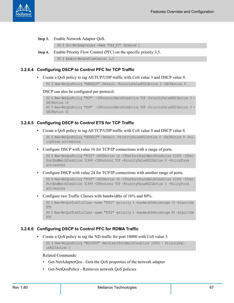
Features Overview and Configuration
Rev 1.80 67Mellanox Technologies
Step 3. Enable Network Adapter QoS.
Step 4. Enable Priority Flow Control (PFC) on the specific priority 3,5.
3.2.6.4 Configuring DSCP to Control PFC for TCP Traffic
• Create a QoS policy to tag All TCP/UDP traffic with CoS value 3 and DSCP value 9.
DSCP can also be configured per protocol.
3.2.6.5 Configuring DSCP to Control ETS for TCP Traffic
• Create a QoS policy to tag All TCP/UDP traffic with CoS value 0 and DSCP value 8.
• Configure DSCP with value 16 for TCP/IP connections with a range of ports.
• Configure DSCP with value 24 for TCP/IP connections with another range of ports.
• Configure two Traffic Classes with bandwidths of 16% and 80%.
3.2.6.6 Configuring DSCP to Control PFC for RDMA Traffic
• Create a QoS policy to tag the ND traffic for port 10000 with CoS value 3.
Related Commands:
• Get-NetAdapterQos - Gets the QoS properties of the network adapter
• Get-NetQosPolicy - Retrieves network QoS policies
PS $ Set-NetAdapterQos -Name "CX4_P1" -Enabled 1
PS $ Enable-NetQosFlowControl 3,5
PS $ New-NetQosPolicy "DEFAULT" -Default -PriorityValue8021Action 3 -DSCPAction 9
PS $ New-NetQosPolicy "TCP" -IPProtocolMatchCondition TCP -PriorityValue8021Action 3 -DSCPAction 16PS $ New-NetQosPolicy "UDP" -IPProtocolMatchCondition UDP -PriorityValue8021Action 3 -DSCPAction 32
PS $ New-NetQosPolicy "DEFAULT" -Default -PriorityValue8021Action 0 -DSCPAction 8 -Pol-icyStore activestore
PS $ New-NetQosPolicy "TCP1" -DSCPAction 16 -IPDstPortStartMatchCondition 31000 -IPDst-PortEndMatchCondition 31999 -IPProtocol TCP -PriorityValue8021Action 0 -PolicyStore activestore
PS $ New-NetQosPolicy "TCP2" -DSCPAction 24 -IPDstPortStartMatchCondition 21000 -IPDst-PortEndMatchCondition 31999 -IPProtocol TCP -PriorityValue8021Action 0 -PolicyStore activestore
PS $ New-NetQosTrafficClass -name "TCP1" -priority 3 -bandwidthPercentage 16 -Algorithm ETSPS $ New-NetQosTrafficClass -name "TCP2" -priority 5 -bandwidthPercentage 80 -Algorithm ETS
PS $ New-NetQosPolicy "ND10000" -NetDirectPortMatchCondition 10000 - PriorityVal-ue8021Action 3
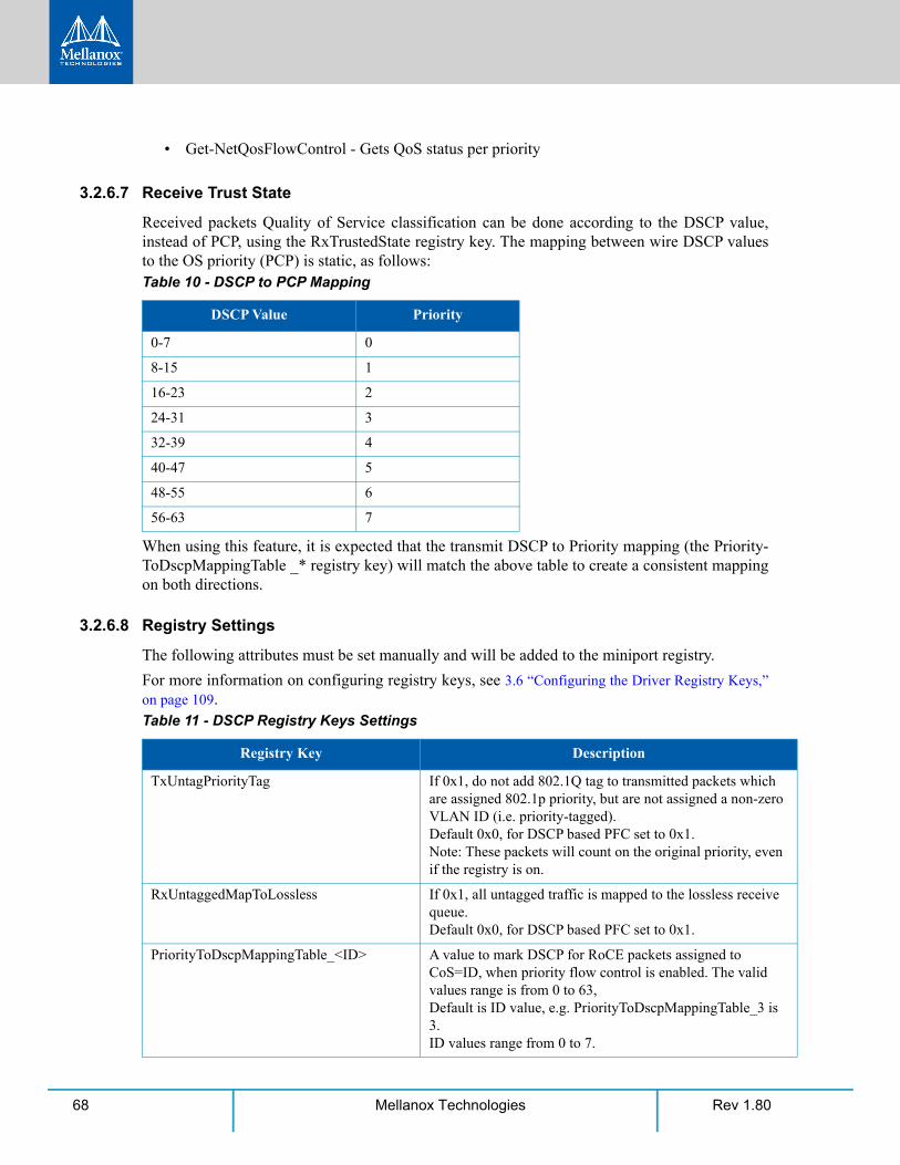
Rev 1.8068 Mellanox Technologies
• Get-NetQosFlowControl - Gets QoS status per priority
3.2.6.7 Receive Trust State
Received packets Quality of Service classification can be done according to the DSCP value, instead of PCP, using the RxTrustedState registry key. The mapping between wire DSCP values to the OS priority (PCP) is static, as follows:
When using this feature, it is expected that the transmit DSCP to Priority mapping (the Priority-ToDscpMappingTable _* registry key) will match the above table to create a consistent mapping on both directions.
3.2.6.8 Registry Settings
The following attributes must be set manually and will be added to the miniport registry.
For more information on configuring registry keys, see 3.6 “Configuring the Driver Registry Keys,” on page 109.
Table 10 - DSCP to PCP Mapping
DSCP Value Priority
0-7 0
8-15 1
16-23 2
24-31 3
32-39 4
40-47 5
48-55 6
56-63 7
Table 11 - DSCP Registry Keys Settings
Registry Key Description
TxUntagPriorityTag If 0x1, do not add 802.1Q tag to transmitted packets which are assigned 802.1p priority, but are not assigned a non-zero VLAN ID (i.e. priority-tagged).Default 0x0, for DSCP based PFC set to 0x1.Note: These packets will count on the original priority, even if the registry is on.
RxUntaggedMapToLossless If 0x1, all untagged traffic is mapped to the lossless receive queue.Default 0x0, for DSCP based PFC set to 0x1.
PriorityToDscpMappingTable_<ID> A value to mark DSCP for RoCE packets assigned to CoS=ID, when priority flow control is enabled. The valid values range is from 0 to 63, Default is ID value, e.g. PriorityToDscpMappingTable_3 is 3. ID values range from 0 to 7.
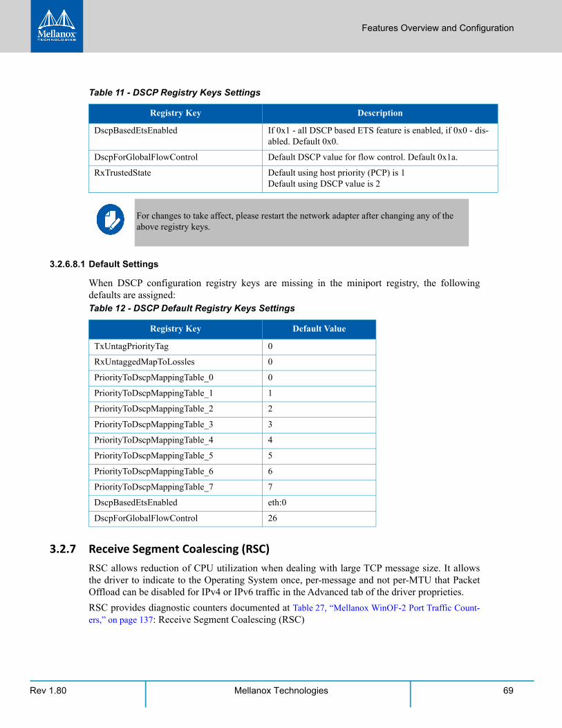
Features Overview and Configuration
Rev 1.80 69Mellanox Technologies
3.2.6.8.1 Default Settings
When DSCP configuration registry keys are missing in the miniport registry, the following defaults are assigned:
3.2.7 Receive Segment Coalescing (RSC)RSC allows reduction of CPU utilization when dealing with large TCP message size. It allows the driver to indicate to the Operating System once, per-message and not per-MTU that Packet Offload can be disabled for IPv4 or IPv6 traffic in the Advanced tab of the driver proprieties.
RSC provides diagnostic counters documented at Table 27, “Mellanox WinOF-2 Port Traffic Count-ers,” on page 137: Receive Segment Coalescing (RSC)
DscpBasedEtsEnabled If 0x1 - all DSCP based ETS feature is enabled, if 0x0 - dis-abled. Default 0x0.
DscpForGlobalFlowControl Default DSCP value for flow control. Default 0x1a.
RxTrustedState Default using host priority (PCP) is 1Default using DSCP value is 2
For changes to take affect, please restart the network adapter after changing any of the above registry keys.
Table 12 - DSCP Default Registry Keys Settings
Registry Key Default Value
TxUntagPriorityTag 0
RxUntaggedMapToLossles 0
PriorityToDscpMappingTable_0 0
PriorityToDscpMappingTable_1 1
PriorityToDscpMappingTable_2 2
PriorityToDscpMappingTable_3 3
PriorityToDscpMappingTable_4 4
PriorityToDscpMappingTable_5 5
PriorityToDscpMappingTable_6 6
PriorityToDscpMappingTable_7 7
DscpBasedEtsEnabled eth:0
DscpForGlobalFlowControl 26
Table 11 - DSCP Registry Keys Settings
Registry Key Description
Rev 1.8070 Mellanox Technologies
3.2.8 Wake on LAN (WoL)Wake on LAN is a technology that allows a network admin to remotely power on a system or to wake it up from sleep mode by a network message. WoL is enabled by default.
3.2.9 Data Center Bridging Exchange (DCBX)Data Center Bridging Exchange (DCBX) protocol is an LLDP based protocol which manages and negotiates host and switch configuration. The WinOF-2 driver supports the following:
• PFC - Priority Flow Control
• ETS - Enhance Transmission Selection
• Application priority
The protocol is widely used to assure lossless path when running multiple protocols at the same time. DCBX is functional as part of configuring QoS mentioned in section Section 3.2.5, “Config-uring Quality of Service (QoS)”, on page 62. Users should make sure the willing bit on the host is enabled, using PowerShell if needed.:
This is required to allow negotiating and accepting peer configurations. Willing bit is set to 1 by default by the operating system.
The new settings can be queried by calling the following command in PowerShell
Note: The below configuration was received from the switch in the below example.
set-NetQosDcbxSetting -Willing 1
Get-NetAdapterQos
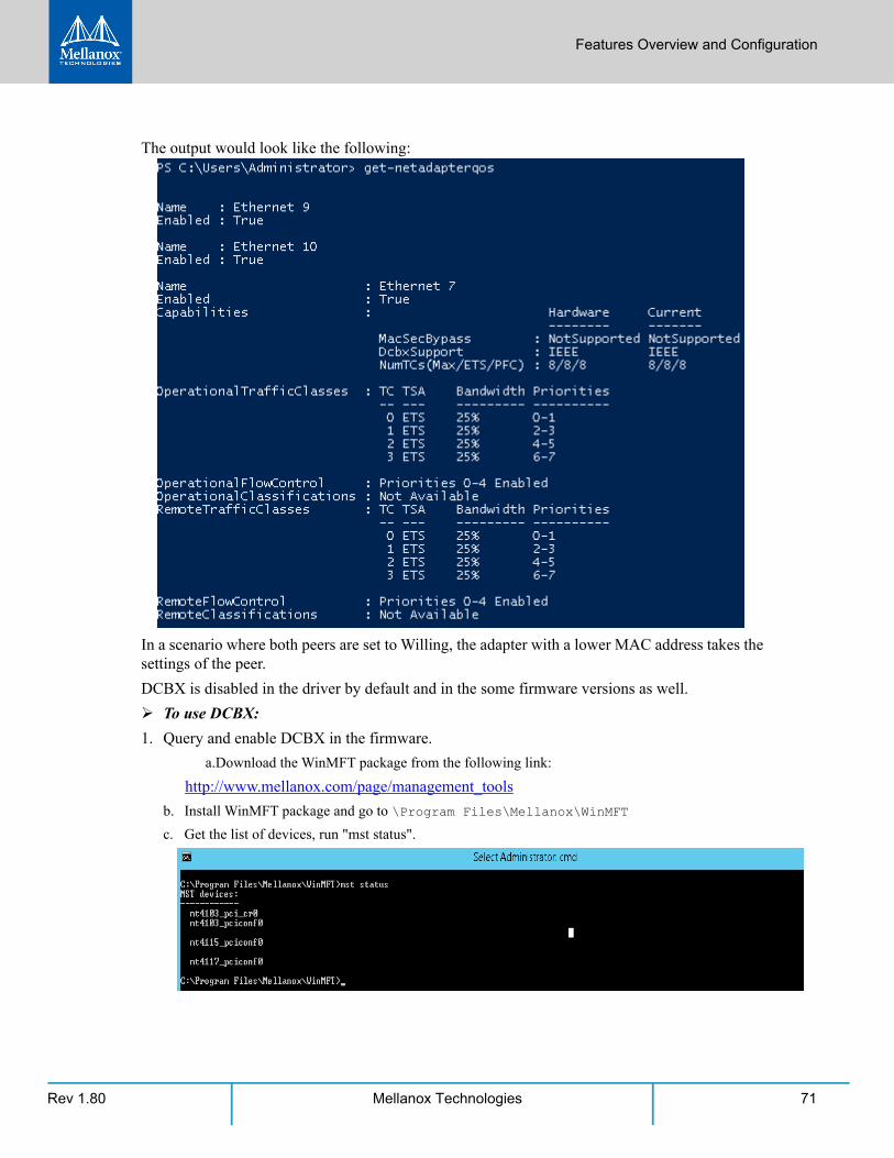
Features Overview and Configuration
Rev 1.80 71Mellanox Technologies
The output would look like the following:
In a scenario where both peers are set to Willing, the adapter with a lower MAC address takes the settings of the peer.
DCBX is disabled in the driver by default and in the some firmware versions as well.
To use DCBX:
1. Query and enable DCBX in the firmware.
a.Download the WinMFT package from the following link:
http://www.mellanox.com/page/management_tools
b. Install WinMFT package and go to \Program Files\Mellanox\WinMFT
c. Get the list of devices, run "mst status".

Rev 1.8072 Mellanox Technologies
d. Verify is the DCBX is enabled or disabled, run "mlxconfig.exe -d mt4117_pciconf0 query".
e. If disabled, run the following commands for a dual-port card.
2. Add the "DcbxMode" registry key, set the value to "2" and reload the adapter. The registry key should be added to HKEY_LOCAL_MACHINE\SYSTEM\CurrentControl-Set\Control\Class\{4d36e972-e325-11ce-bfc1-08002be10318}\<IndexValue> To find the IndexValue, refer to Section 3.6.1, “Finding the Index Value of the Network Interface”, on page 110
3.2.10 Receive Path Activity MonitoringIn the event where the device or the Operating System unexpectedly becomes unresponsive for a long period of time, the Flow Control mechanism may send pause frames, which will cause con-gestion spreading to the entire network.
To prevent this scenario, the device monitors its status continuously, attempting to detect when the receive pipeline is stalled. When the device detects a stall for a period longer than a pre-con-figured timeout, the Flow Control mechanisms (Global Pause and PFC) are automatically dis-abled.
mlxconfig -d mt4117_pciconf0 set LLDP_NB_RX_MODE_P1=2mlxconfig -d mt4117_pciconf0 set LLDP_NB_TX_MODE_P1=2mlxconfig -d mt4117_pciconf0 set LLDP_NB_DCBX_P1=1mlxconfig -d mt4117_pciconf0 set LLDP_NB_RX_MODE_P2=2mlxconfig -d mt4117_pciconf0 set LLDP_NB_TX_MODE_P2=2mlxconfig -d mt4117_pciconf0 set LLDP_NB_DCBX_P2=1
Features Overview and Configuration
Rev 1.80 73Mellanox Technologies
If the PFC is in use, and one or more priorities are stalled, the PFC will be disabled on all priori-ties. When the device detects that the stall has ceased, the flow control mechanism will resume with its previously configured behavior.
Two registry parameters control the mechanism’s behavior: the DeviceRxStallTime-out key con-trols the time threshold for disabling the flow control, and the DeviceRxStallWatermark key con-trols a diagnostics counter that can be used for early detection of stalled receive. WinOF-2 provides two counters to monitor the activity of this feature: "Minor Stall Watermark Reached" and "Criti-cal Stall Watermark Reached". For more information, see Table 20 - “Ethernet Registry Keys,” on page 118.
3.2.11 Head of Queue Lifetime LimitThis feature enables the system to drop the packets that have been awaiting transmission for a long period of time, preventing the system from hanging. The implementation of the feature complies with the Head of Queue Lifetime Limit (HLL) definition in the InfiniBand™ Architec-ture Specification (see Table 4 - “Related Documents,” on page 20).
The HLL has three registry keys for configuration:
TCHeadOfQueueLifeTimeLimit, TCStallCount and TCHeadOfQueueLifeTimeLimitEnable (see Table 20 - “Ethernet Registry Keys,” on page 118).
3.2.12 VXLANVXLAN technology provides scalability and security challenges solutions. It requires extension of the traditional stateless offloads to avoid performance drop. ConnectX®-4 and onwards adapter cards offer stateless offloads for a VXLAN packet, similar to the ones offered to non-encapsulated packets. VXLAN protocol encapsulates its packets using outer UDP header.
ConnectX®-4 and onwards support offloading of tasks related to VXLAN packet processing, such as TCP header checksum and VMQ (i.e.: directing incoming VXLAN packets to the appro-priate VM queue).
Due to hardware limitation, on a dual-port adapter, VXLAN offload service cannot be provided simultaneously for both Ethernet ports if they are not using the same UDP port for VXLAN tun-neling.
VXLAN can be configured using the standardized *VxlanUDPPortNumber and *Encapsulated-PacketTaskOffloadVxlan keys.
Restart the driver
3.2.13 Threaded DPC A threaded DPC is a DPC that the system executes at IRQL = PASSIVE_LEVEL. An ordinary DPC preempts the execution of all threads, and cannot be preempted by a thread or by another DPC. If the system has a large number of ordinary DPCs queued, or if one of those DPCs runs for a long period time, every thread will remain paused for an arbitrarily long period of time. Thus, each ordinary DPC increases the system latency, which can damage the performance of time-sen-sitive applications, such as audio or video playback.

Rev 1.8074 Mellanox Technologies
Conversely, a threaded DPC can be preempted by an ordinary DPC, but not by other threads. Therefore, the user should use threaded DPCs rather than ordinary DPCs, unless a particular DPC must not be preempted, even by another DPC.
For more information, please refer to Introduction to Threaded DPCs.
Features Overview and Configuration
Rev 1.80 75Mellanox Technologies
3.3 InfiniBand Network
3.3.1 Supported IPoIB Capabilities/FeaturesThe following are IPoIB supported capabilities/features:
• “Port Management”
• “Assigning Port IP After Installation”
• “Modifying Driver’s Configuration”
• “Receive Side Scaling (RSS)”
• “Displaying Adapter Related Information”
3.3.2 Unsupported IPoIB Capabilities/FeaturesThe following features are not supported
• VXLAN
• NVGRE
• Receive Side Coalescing (RSC)
• VLAN
• PKeys
3.4 Storage Protocols
3.4.1 Deploying SMB DirectThe Server Message Block (SMB) protocol is a network file sharing protocol implemented in Microsoft Windows. The set of message packets that defines a particular version of the protocol is called a dialect.
The Microsoft SMB protocol is a client-server implementation and consists of a set of data pack-ets, each containing a request sent by the client or a response sent by the server.
SMB protocol is used on top of the TCP/IP protocol or other network protocols. Using the SMB protocol allows applications to access files or other resources on a remote server, to read, create, and update them. In addition, it enables communication with any server program that is set up to receive an SMB client request.
3.4.1.1 SMB Configuration Verification
3.4.1.1.1 Verifying Network Adapter Configuration
Use the following PowerShell cmdlets to verify Network Direct is globally enabled and that you have NICs with the RDMA capability.
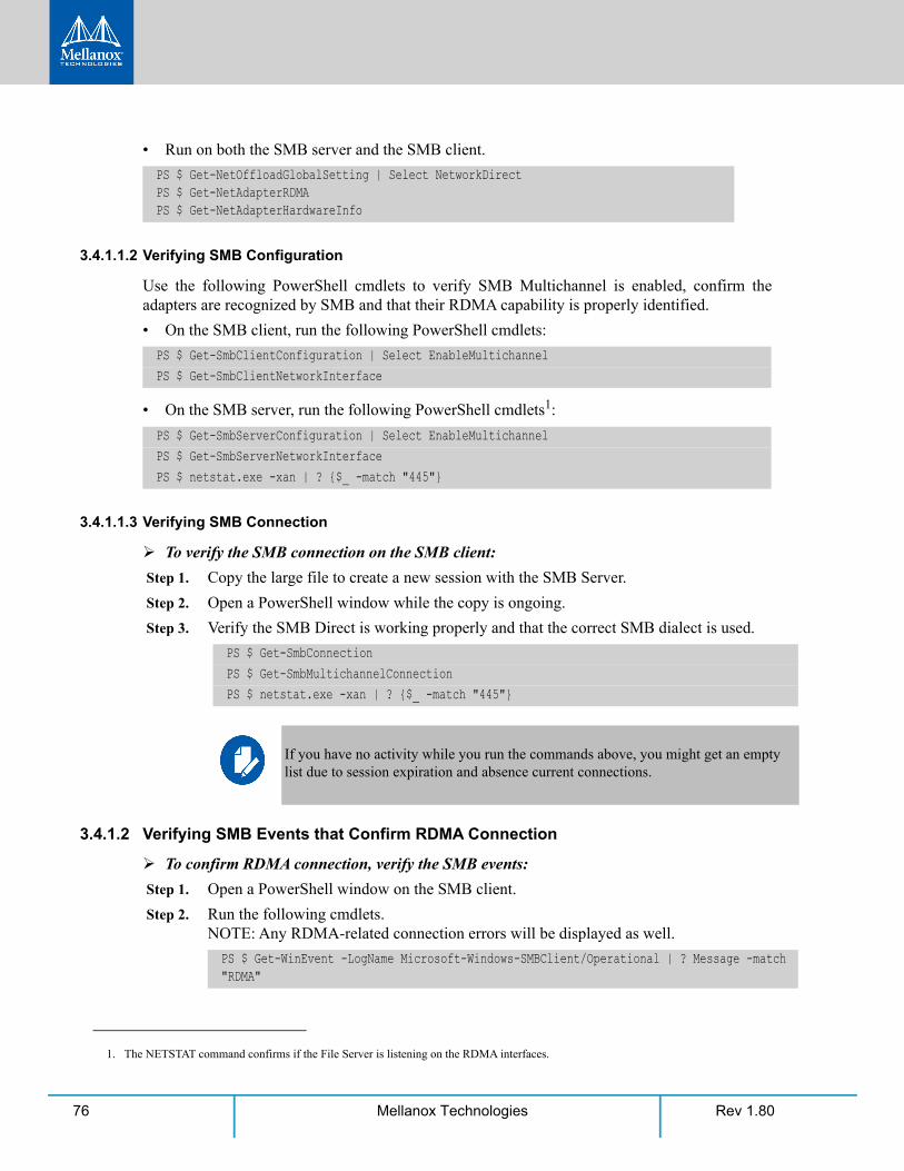
Rev 1.8076 Mellanox Technologies
• Run on both the SMB server and the SMB client.
3.4.1.1.2 Verifying SMB Configuration
Use the following PowerShell cmdlets to verify SMB Multichannel is enabled, confirm the adapters are recognized by SMB and that their RDMA capability is properly identified.
• On the SMB client, run the following PowerShell cmdlets:
• On the SMB server, run the following PowerShell cmdlets1:
3.4.1.1.3 Verifying SMB Connection
To verify the SMB connection on the SMB client:
Step 1. Copy the large file to create a new session with the SMB Server.
Step 2. Open a PowerShell window while the copy is ongoing.
Step 3. Verify the SMB Direct is working properly and that the correct SMB dialect is used.
3.4.1.2 Verifying SMB Events that Confirm RDMA Connection
To confirm RDMA connection, verify the SMB events:
Step 1. Open a PowerShell window on the SMB client.
Step 2. Run the following cmdlets. NOTE: Any RDMA-related connection errors will be displayed as well.
PS $ Get-NetOffloadGlobalSetting | Select NetworkDirect PS $ Get-NetAdapterRDMA PS $ Get-NetAdapterHardwareInfo
PS $ Get-SmbClientConfiguration | Select EnableMultichannel PS $ Get-SmbClientNetworkInterface
PS $ Get-SmbServerConfiguration | Select EnableMultichannel PS $ Get-SmbServerNetworkInterface PS $ netstat.exe -xan | ? {$_ -match "445"}
1. The NETSTAT command confirms if the File Server is listening on the RDMA interfaces.
PS $ Get-SmbConnection PS $ Get-SmbMultichannelConnection PS $ netstat.exe -xan | ? {$_ -match "445"}
If you have no activity while you run the commands above, you might get an empty list due to session expiration and absence current connections.
PS $ Get-WinEvent -LogName Microsoft-Windows-SMBClient/Operational | ? Message -match "RDMA"
Features Overview and Configuration
Rev 1.80 77Mellanox Technologies
3.5 Virtualization
3.5.1 Hyper-V with VMQ
3.5.1.1 System Requirements
Operating Systems: Windows Server 2012 and above.
3.5.1.2 Using Hyper-V with VMQ
Mellanox WinOF-2 Rev 1.80 includes a Virtual Machine Queue (VMQ) interface to support Microsoft Hyper-V network performance improvements and security enhancement.
VMQ interface supports:
• Classification of received packets by using the destination MAC address to route the packets to different receive queues
• NIC ability to use DMA to transfer packets directly to a Hyper-V child-partition's shared memory
• Scaling to multiple processors, by processing packets for different virtual machines on different processors.
To enable Hyper-V with VMQ using UI:
Step 1. Open Hyper-V Manager.
Step 2. Right-click the desired Virtual Machine (VM), and left-click Settings in the pop-up menu.
Step 3. In the Settings window, under the relevant network adapter, select “Hardware Accelera-tion”.
Step 4. Check/uncheck the box “Enable virtual machine queue” to enable/disable VMQ on that spe-cific network adapter.
To enable Hyper-V with VMQ using PowerShell:
Step 1. Enable VMQ on a specific VM: Set-VMNetworkAdapter <VM Name> -VmqWeight 100
Step 2. Disable VMQ on a specific VM: Set-VMNetworkAdapter <VM Name> -VmqWeight 0
For further details on how to configure the switches to be lossless, please refer to https://community.mellanox.com
Rev 1.8078 Mellanox Technologies
3.5.2 Network Virtualization using Generic Routing Encapsulation (NVGRE)
3.5.2.1 System Requirements
Operating Systems: Windows Server 2012 R2 and above.
3.5.2.2 Using NVGRE
Network Virtualization using Generic Routing Encapsulation (NVGRE) is a network virtualiza-tion technology that attempts to alleviate the scalability problems associated with large cloud computing deployments. It uses Generic Routing Encapsulation (GRE) to tunnel layer 2 packets across an IP fabric, and uses 24 bits of the GRE key as a logical network discriminator (which is called a tenant network ID).
Configuring the Hyper-V Network Virtualization, requires two types of IP addresses:
• Provider Addresses (PA) - unique IP addresses assigned to each Hyper-V host that are routable across the physical network infrastructure. Each Hyper-V host requires at least one PA to be assigned.
• Customer Addresses (CA) - unique IP addresses assigned to each Virtual Machine that participate on a virtualized network. Using NVGRE, multiple CAs for VMs running on a Hyper-V host can be tunneled using a single PA on that Hyper-V host. CAs must be unique across all VMs on the same virtual network, but they do not need to be unique across virtual networks with different Virtual Subnet ID.
The VM generates a packet with the addresses of the sender and the recipient within the CA space. Then Hyper-V host encapsulates the packet with the addresses of the sender and the recip-ient in PA space.
PA addresses are determined by using Virtualization table. Hyper-V host retrieves the received packet, identifies recipient and forwards the original packet with the CA addresses to the desired VM.
NVGRE can be implemented across an existing physical IP network without requiring changes to physical network switch architecture. Since NVGRE tunnels terminate at each Hyper-V host, the hosts handle all encapsulation and de-encapsulation of the network traffic. Firewalls that block GRE tunnels between sites have to be configured to support forwarding GRE (IP Protocol 47) tunnel traffic.
For further details on configuring NVGRE, please refer to Appendix A,“NVGRE Configuration Scripts Examples,” on page 203
Network Virtualization using Generic Routing Encapsulation (NVGRE) offload is currently sup-ported in Windows Server 2012 R2 with the latest updates for Microsoft.
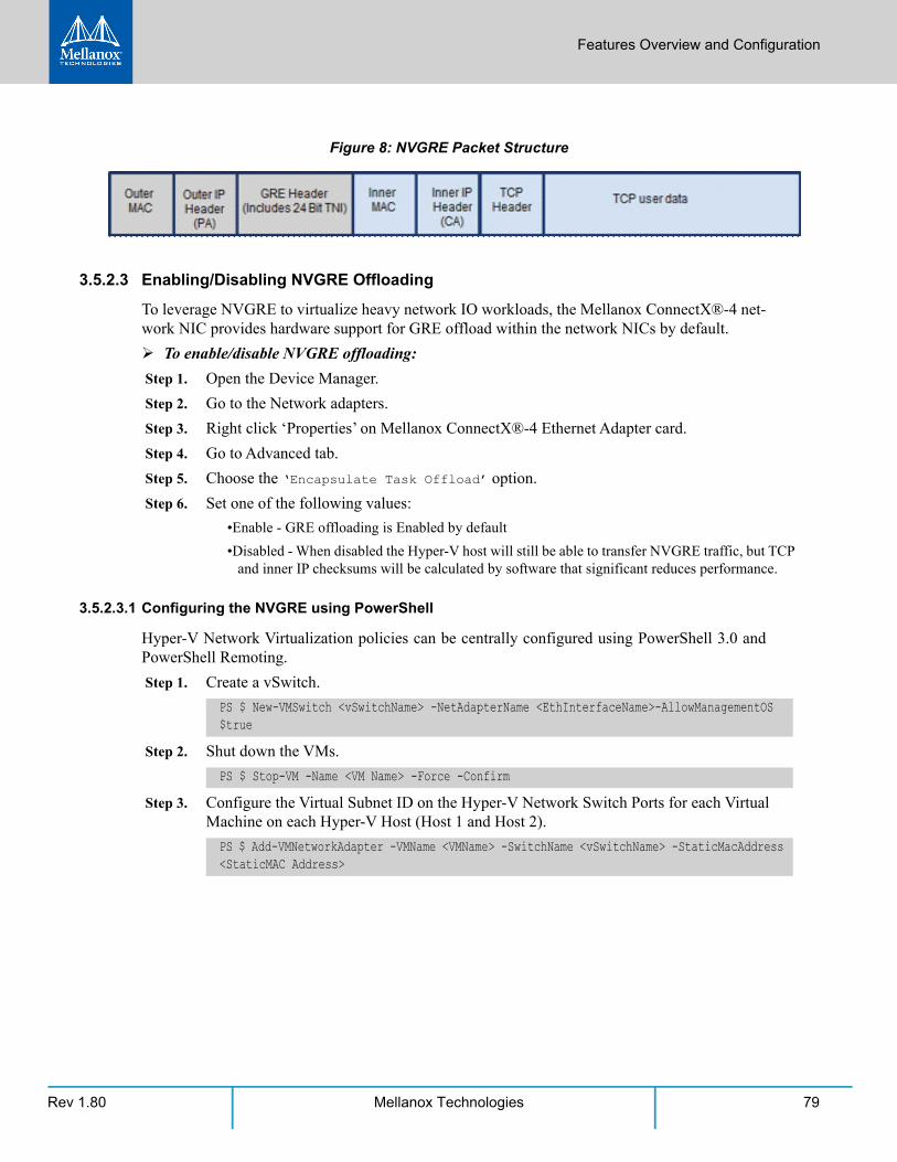
Features Overview and Configuration
Rev 1.80 79Mellanox Technologies
Figure 8: NVGRE Packet Structure
3.5.2.3 Enabling/Disabling NVGRE Offloading
To leverage NVGRE to virtualize heavy network IO workloads, the Mellanox ConnectX®-4 net-work NIC provides hardware support for GRE offload within the network NICs by default.
To enable/disable NVGRE offloading:
Step 1. Open the Device Manager.
Step 2. Go to the Network adapters.
Step 3. Right click ‘Properties’ on Mellanox ConnectX®-4 Ethernet Adapter card.
Step 4. Go to Advanced tab.
Step 5. Choose the ‘Encapsulate Task Offload’ option.
Step 6. Set one of the following values:
•Enable - GRE offloading is Enabled by default
•Disabled - When disabled the Hyper-V host will still be able to transfer NVGRE traffic, but TCP and inner IP checksums will be calculated by software that significant reduces performance.
3.5.2.3.1 Configuring the NVGRE using PowerShell
Hyper-V Network Virtualization policies can be centrally configured using PowerShell 3.0 and PowerShell Remoting.
Step 1. Create a vSwitch.
Step 2. Shut down the VMs.
Step 3. Configure the Virtual Subnet ID on the Hyper-V Network Switch Ports for each Virtual Machine on each Hyper-V Host (Host 1 and Host 2).
PS $ New-VMSwitch <vSwitchName> -NetAdapterName <EthInterfaceName>-AllowManagementOS $true
PS $ Stop-VM -Name <VM Name> -Force -Confirm
PS $ Add-VMNetworkAdapter -VMName <VMName> -SwitchName <vSwitchName> -StaticMacAddress <StaticMAC Address>
Rev 1.8080 Mellanox Technologies
Step 4. Configure a Subnet Locator and Route records on all Hyper-V Hosts (same command on all Hyper-V hosts)
Step 5. Add customer route on all Hyper-V hosts (same command on all Hyper-V hosts).
Step 6. Configure the Provider Address and Route records on each Hyper-V Host using an appro-priate interface name and IP address.
Step 7. Configure the Virtual Subnet ID on the Hyper-V Network Switch Ports for each Virtual Machine on each Hyper-V Host (Host 1 and Host 2).
3.5.2.4 Verifying the Encapsulation of the Traffic
Once the configuration using PowerShell is completed, verifying that packets are indeed encap-sulated as configured is possible through any packet capturing utility. If configured correctly, an encapsulated packet should appear as a packet consisting of the following headers:
Outer ETH Header, Outer IP, GRE Header, Inner ETH Header, Original Ethernet Payload.
PS $ New-NetVirtualizationLookupRecord -CustomerAddress <VMInterfaceIPAddress 1/n> -ProviderAddress <HypervisorInterfaceIPAddress1> -VirtualSubnetID <virtualsubnetID> -
MACAddress <VMmacaddress1>a -Rule "TranslationMethodEncap"
PS $ New-NetVirtualizationLookupRecord -CustomerAddress <VMInterfaceIPAddress 2/n> -ProviderAddress <HypervisorInterfaceIPAddress2> -VirtualSubnetID <virtualsubnetID> -
MACAddress <VMmacaddress2>a -Rule "TranslationMethodEncap"
a. This is the VM’s MAC address associated with the vSwitch connected to the Mellanox device.
PS $ New-NetVirtualizationCustomerRoute -RoutingDomainID "{11111111-2222-3333-4444-000000005001}" -VirtualSubnetID <virtualsubnetID> -DestinationPrefix <VMInterfaceIPAd-dress/Mask> -NextHop "0.0.0.0" -Metric 255
PS $ $NIC = Get-NetAdapter <EthInterfaceName>PS $ New-NetVirtualizationProviderAddress -InterfaceIndex $NIC.InterfaceIndex -Provid-erAddress <HypervisorInterfaceIPAddress> -PrefixLength 24
PS $ New-NetVirtualizationProviderRoute -InterfaceIndex $NIC.InterfaceIndex -Destina-tionPrefix "0.0.0.0/0" -NextHop <HypervisorInterfaceIPAddress>
PS $ Get-VMNetworkAdapter -VMName <VMName> | where {$_.MacAddress –eq <VMmacaddress1>} | Set-VMNetworkAdapter -VirtualSubnetID <virtualsubnetID>
Please repeat steps 5 to 8 on each Hyper-V after rebooting the Hypervisor.
Features Overview and Configuration
Rev 1.80 81Mellanox Technologies
3.5.2.5 Removing NVGRE configuration
Step 1. Set VSID back to 0 (on each Hyper-V for each Virtual Machine where VSID was set)
•VMName - the name of Virtual machine
•VMMacAddress - the MAC address of VM's network interface associated with vSwitch that was connected to Mellanox device.
Step 2. Remove all lookup records (same command on all Hyper-V hosts).
Step 3. Remove customer route (same command on all Hyper-V hosts).
Step 4. Remove Provider address (same command on all Hyper-V hosts).
Step 5. Remove provider routed for a Hyper-V host.
Step 6. For HyperV running Windows Server 2012 only disable network adapter binding to ms_-netwnv service
3.5.3 Single Root I/O Virtualization (SR-IOV)Single Root I/O Virtualization (SR-IOV) is a technology that allows a physical PCIe device to present itself multiple times through the PCIe bus. This technology enables multiple virtual instances of the device with separate resources. Mellanox adapters are capable of exposing up to 96 virtual instances called Virtual Functions (VFs) per port. These virtual functions can then be provisioned separately. Each VF can be seen as an addition device connected to the Physical Function. It also shares resources with the Physical Function.
SR-IOV is commonly used in conjunction with an SR-IOV enabled hypervisor to provide virtual machines direct hardware access to network resources hence increasing its performance.
This guide demonstrates the setup and configuration of SR-IOV, using Mellanox adapter cards family. SR-IOV VF is a single port device.
PS $ Get-VMNetworkAdapter <VMName>(a) | where {$_.MacAddress -eq <VMMacAddress>(b)} | Set-VMNetworkAdapter -VirtualSubnetID 0
PS $ Remove-NetVirtualizationLookupRecord
PS $ Remove-NetVirtualizationCustomerRoute
PS $ Remove-NetVirtualizationProviderAddress
PS $ Remove-NetVirtualizationProviderRoute
PS $ Disable-NetAdapterBinding <EthInterfaceName>(a) -ComponentID ms_netwnv<EthInterfaceName> - Physical NIC name
Rev 1.8082 Mellanox Technologies
3.5.3.1 SR-IOV over Hyper-V
3.5.3.1.1 System Requirements
• A server and BIOS with SR-IOV support. BIOS settings may require an update to enable virtualization support and SR-IOV support
• Hypervisor OS: Windows Server 2012 R2, Windows Server 2016
• Virtual Machine (VM) OS: The VM OS can be Windows Server 2012 and above, or Linux
• Mellanox ConnectX®-4 VPI adapter card
• SR-IOV supporting driver version:
• SR-IOV Ethernet over Hyper-V: WinOF-2 v1.20 or higher
• SR-IOV IPoIB over Hyper-V and the guest: WinOF-2 v1.80 or higher
3.5.3.1.2 Feature Limitations
• RDMA (i.e RoCE) capability is not available in SR-IOV mode for Ethernet
• IPoIB in SR-IOV:
• LID based IPoIB is supported with the following limitations:
• Does not support routers in the fabric
• Supports up to 2^15-1 LIDs
• No synthetic path: The SR-IOV path that goes thru the WinOF-2 driver
• Although both Mellanox adapter - Virtual Function (VF) and the NetVSC will be presented in the
VM, only the Mellanox interface should be used.
3.5.3.2 Configuring SR-IOV Host Machines
The following are the necessary steps for configuring host machines:
3.5.3.2.1 Enabling SR-IOV in BIOS
Depending on your system, perform the steps below to set up your BIOS. The figures used in this section are for illustration purposes only.
For further information, please refer to the appropriate BIOS User Manual.
To enable SR-IOV in BIOS:
Step 1. Make sure the machine’s BIOS supports SR-IOV.
Please, consult BIOS vendor website for SR-IOV supported BIOS versions list. Update the BIOS version if necessary.
Step 2. Follow BIOS vendor guidelines to enable SR-IOV according to BIOS User Manual. For example:
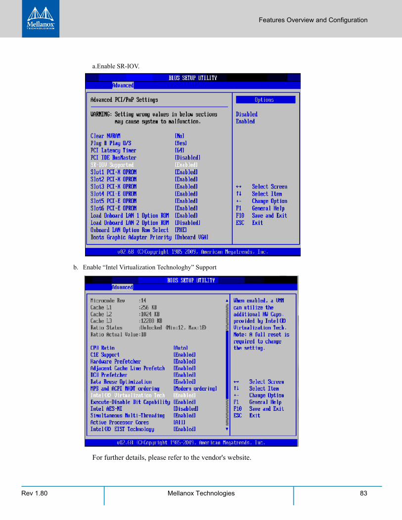
Features Overview and Configuration
Rev 1.80 83Mellanox Technologies
a.Enable SR-IOV.
b. Enable “Intel Virtualization Technologhy” Support
For further details, please refer to the vendor's website.
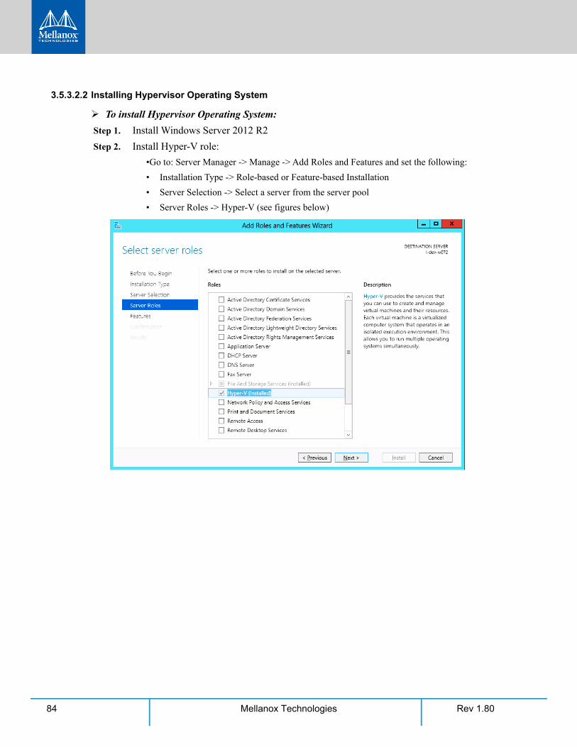
Rev 1.8084 Mellanox Technologies
3.5.3.2.2 Installing Hypervisor Operating System
To install Hypervisor Operating System:
Step 1. Install Windows Server 2012 R2
Step 2. Install Hyper-V role:
•Go to: Server Manager -> Manage -> Add Roles and Features and set the following:
• Installation Type -> Role-based or Feature-based Installation
• Server Selection -> Select a server from the server pool
• Server Roles -> Hyper-V (see figures below)

Features Overview and Configuration
Rev 1.80 85Mellanox Technologies
Step 3. Install Hyper-V Management Tools.
Features - > Remote Server Administration Tools -> Role Administration Tools -> Hyper-V Administration Tool.
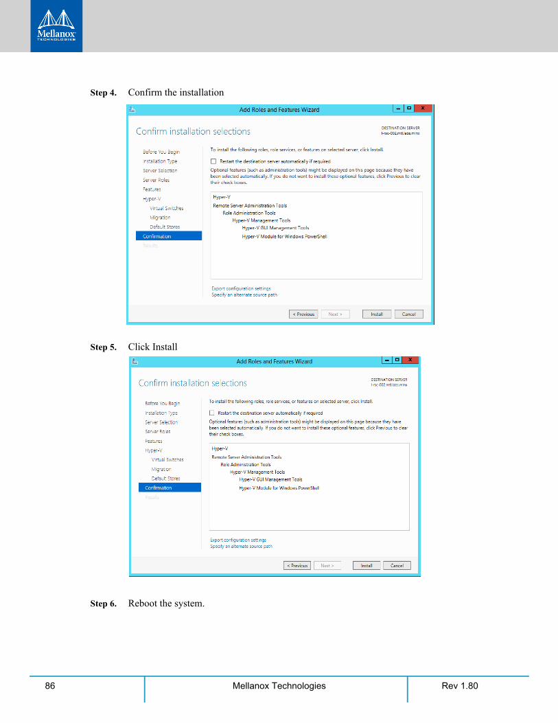
Rev 1.8086 Mellanox Technologies
Step 4. Confirm the installation
Step 5. Click Install
Step 6. Reboot the system.
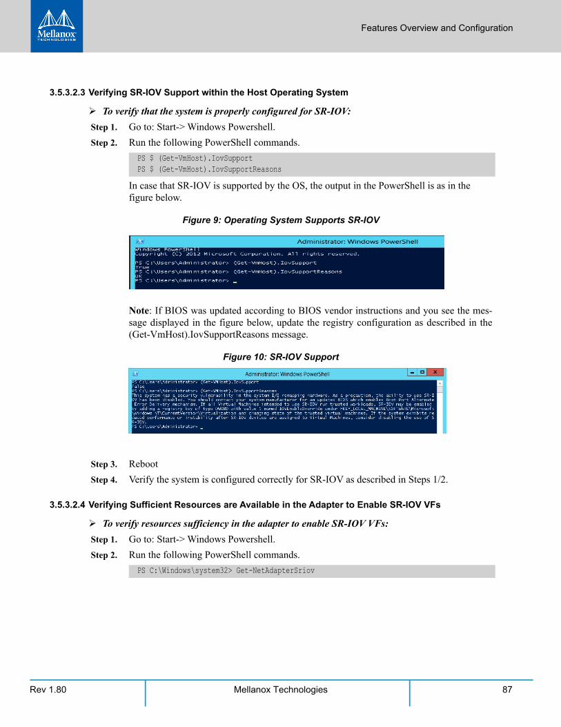
Features Overview and Configuration
Rev 1.80 87Mellanox Technologies
3.5.3.2.3 Verifying SR-IOV Support within the Host Operating System
To verify that the system is properly configured for SR-IOV:
Step 1. Go to: Start-> Windows Powershell.
Step 2. Run the following PowerShell commands.
In case that SR-IOV is supported by the OS, the output in the PowerShell is as in the figure below.
Figure 9: Operating System Supports SR-IOV
Note: If BIOS was updated according to BIOS vendor instructions and you see the mes-sage displayed in the figure below, update the registry configuration as described in the (Get-VmHost).IovSupportReasons message.
Figure 10: SR-IOV Support
Step 3. Reboot
Step 4. Verify the system is configured correctly for SR-IOV as described in Steps 1/2.
3.5.3.2.4 Verifying Sufficient Resources are Available in the Adapter to Enable SR-IOV VFs
To verify resources sufficiency in the adapter to enable SR-IOV VFs:
Step 1. Go to: Start-> Windows Powershell.
Step 2. Run the following PowerShell commands.
PS $ (Get-VmHost).IovSupportPS $ (Get-VmHost).IovSupportReasons
PS C:\Windows\system32> Get-NetAdapterSriov

Rev 1.8088 Mellanox Technologies
Example:
For further information, see https://technet.microsoft.com/en-us/library/jj130915(v=wps.630).aspx
3.5.3.2.5 Creating a Virtual Machine
To create a virtual machine
Step 1. Go to: Server Manager -> Tools -> Hyper-V Manager.
Step 2. Go to: New->Virtual Machine and set the following:
•Name: <name>
•Startup memory: 4096 MB
•Connection: Not Connected
Name : SLOT 4 Port 1InterfaceDescription : Mellanox ConnectX-4 AdapterEnabled : TrueSriovSupport : NoVfBarSpaceSwitchName : “Default Switch”NumVFs : 32
If the “SriovSupport” field value shows “NoVfBarSpace”, SR-IOV cannot be used on this network adapter as there are not enough PCI Express BAR resources available.
To use SR-IOV, you need to reduce the number of VFs to the number supported by the OS.
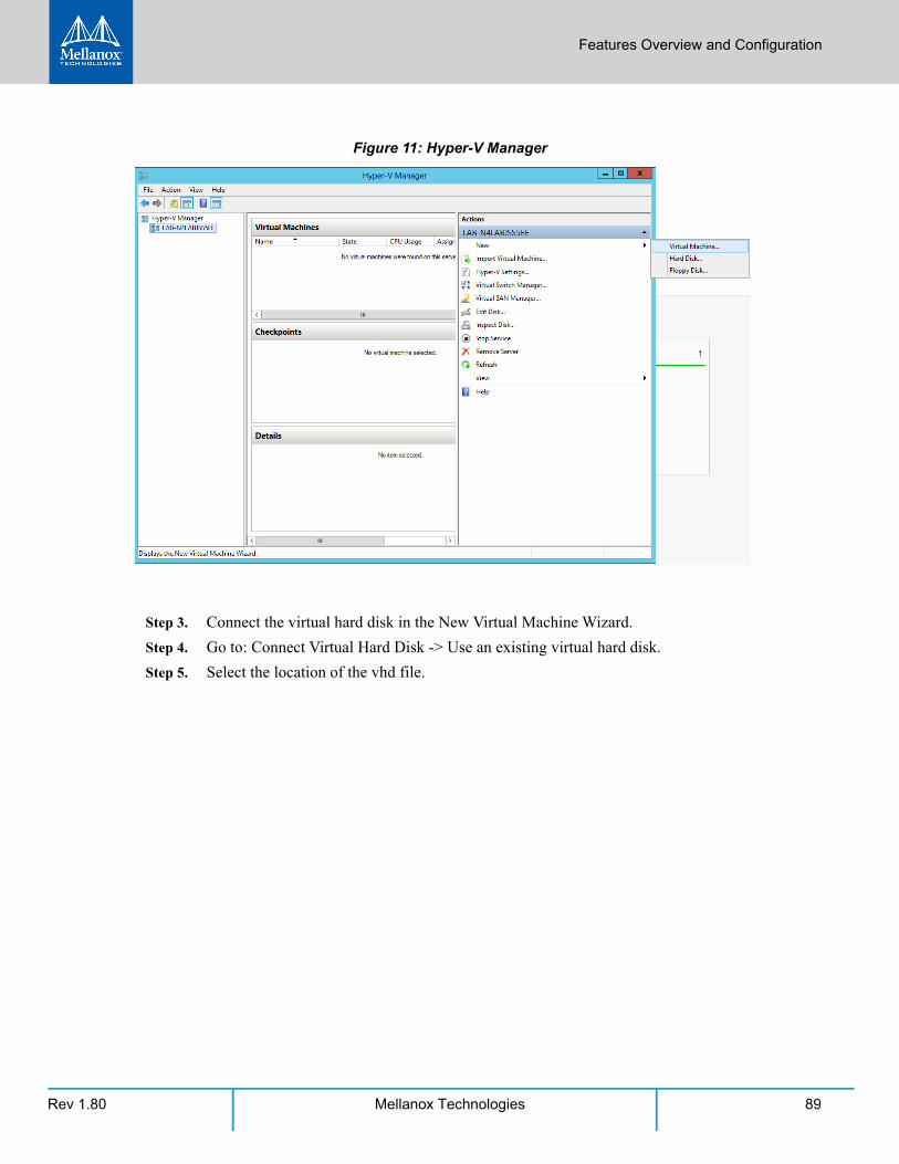
Features Overview and Configuration
Rev 1.80 89Mellanox Technologies
Figure 11: Hyper-V Manager
Step 3. Connect the virtual hard disk in the New Virtual Machine Wizard.
Step 4. Go to: Connect Virtual Hard Disk -> Use an existing virtual hard disk.
Step 5. Select the location of the vhd file.
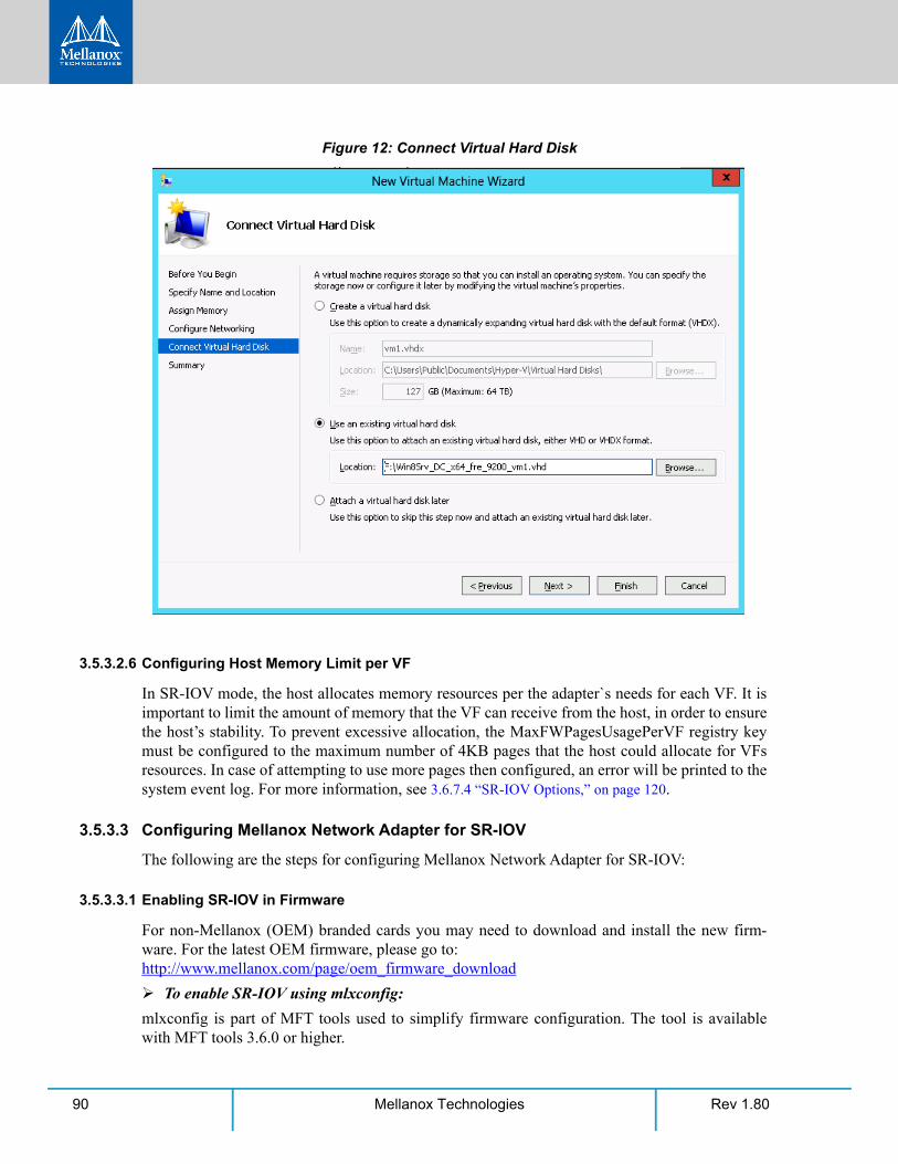
Rev 1.8090 Mellanox Technologies
Figure 12: Connect Virtual Hard Disk
3.5.3.2.6 Configuring Host Memory Limit per VF
In SR-IOV mode, the host allocates memory resources per the adapter`s needs for each VF. It is important to limit the amount of memory that the VF can receive from the host, in order to ensure the host’s stability. To prevent excessive allocation, the MaxFWPagesUsagePerVF registry key must be configured to the maximum number of 4KB pages that the host could allocate for VFs resources. In case of attempting to use more pages then configured, an error will be printed to the system event log. For more information, see 3.6.7.4 “SR-IOV Options,” on page 120.
3.5.3.3 Configuring Mellanox Network Adapter for SR-IOV
The following are the steps for configuring Mellanox Network Adapter for SR-IOV:
3.5.3.3.1 Enabling SR-IOV in Firmware
For non-Mellanox (OEM) branded cards you may need to download and install the new firm-ware. For the latest OEM firmware, please go to: http://www.mellanox.com/page/oem_firmware_download
To enable SR-IOV using mlxconfig:
mlxconfig is part of MFT tools used to simplify firmware configuration. The tool is available with MFT tools 3.6.0 or higher.
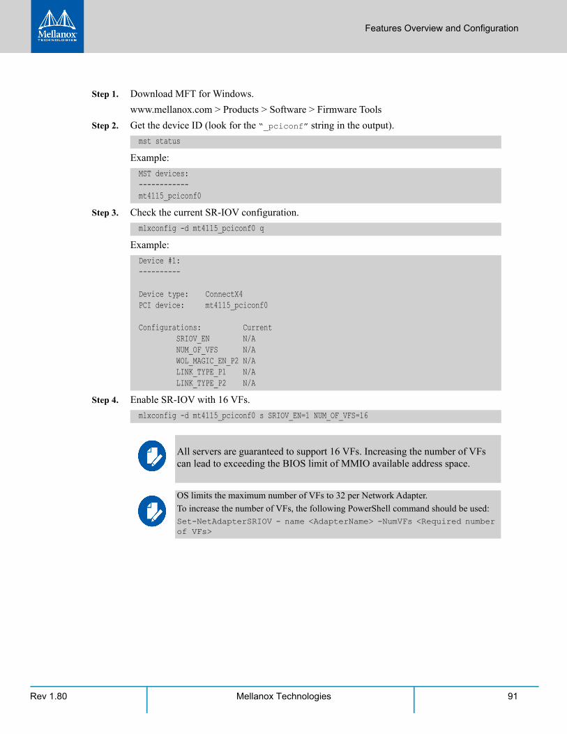
Features Overview and Configuration
Rev 1.80 91Mellanox Technologies
Step 1. Download MFT for Windows.
www.mellanox.com > Products > Software > Firmware Tools
Step 2. Get the device ID (look for the “_pciconf” string in the output).
Example:
Step 3. Check the current SR-IOV configuration.
Example:
Step 4. Enable SR-IOV with 16 VFs.
mst status
MST devices:------------mt4115_pciconf0
mlxconfig -d mt4115_pciconf0 q
Device #1:----------
Device type: ConnectX4PCI device: mt4115_pciconf0
Configurations: Current SRIOV_EN N/A NUM_OF_VFS N/A WOL_MAGIC_EN_P2 N/A LINK_TYPE_P1 N/A LINK_TYPE_P2 N/A
mlxconfig -d mt4115_pciconf0 s SRIOV_EN=1 NUM_OF_VFS=16
All servers are guaranteed to support 16 VFs. Increasing the number of VFs can lead to exceeding the BIOS limit of MMIO available address space.
OS limits the maximum number of VFs to 32 per Network Adapter.
To increase the number of VFs, the following PowerShell command should be used:Set-NetAdapterSRIOV - name <AdapterName> -NumVFs <Required number of VFs>
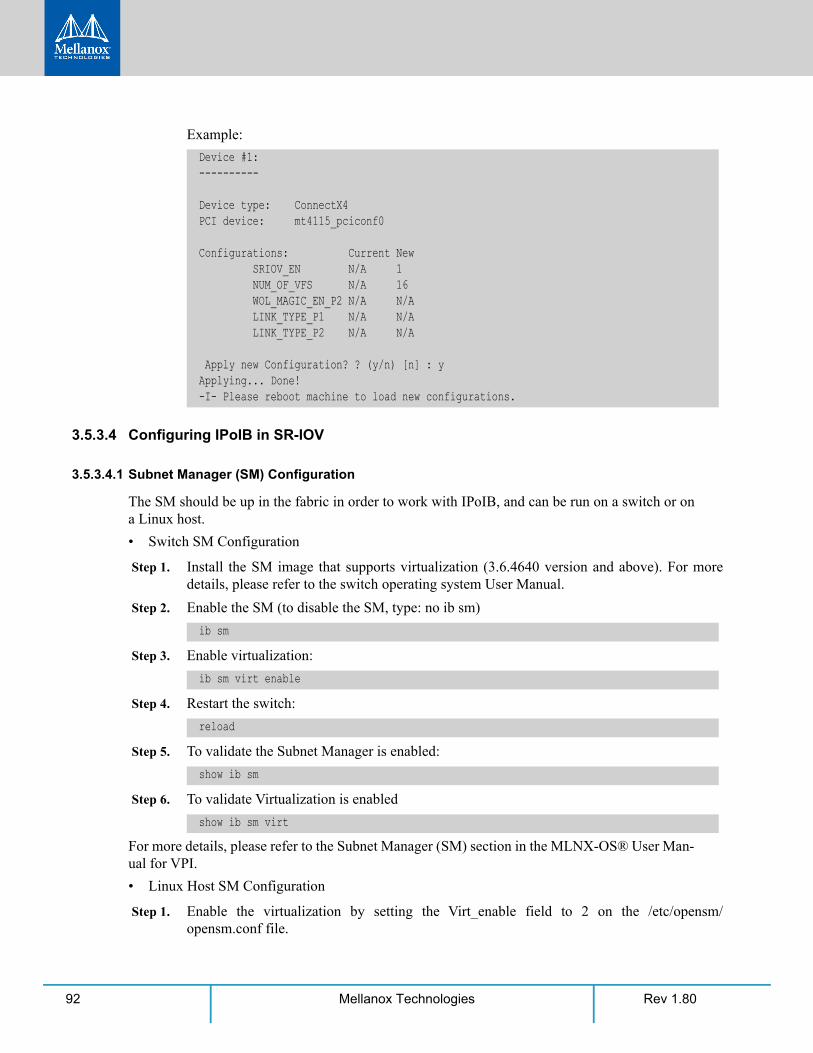
Rev 1.8092 Mellanox Technologies
Example:
3.5.3.4 Configuring IPoIB in SR-IOV
3.5.3.4.1 Subnet Manager (SM) Configuration
The SM should be up in the fabric in order to work with IPoIB, and can be run on a switch or on a Linux host.
• Switch SM Configuration
Step 1. Install the SM image that supports virtualization (3.6.4640 version and above). For more details, please refer to the switch operating system User Manual.
Step 2. Enable the SM (to disable the SM, type: no ib sm)
Step 3. Enable virtualization:
Step 4. Restart the switch:
Step 5. To validate the Subnet Manager is enabled:
Step 6. To validate Virtualization is enabled
For more details, please refer to the Subnet Manager (SM) section in the MLNX-OS® User Man-ual for VPI.
• Linux Host SM Configuration
Step 1. Enable the virtualization by setting the Virt_enable field to 2 on the /etc/opensm/opensm.conf file.
Device #1:----------
Device type: ConnectX4PCI device: mt4115_pciconf0
Configurations: Current New SRIOV_EN N/A 1 NUM_OF_VFS N/A 16 WOL_MAGIC_EN_P2 N/A N/A LINK_TYPE_P1 N/A N/A LINK_TYPE_P2 N/A N/A
Apply new Configuration? ? (y/n) [n] : yApplying... Done!-I- Please reboot machine to load new configurations.
ib sm
ib sm virt enable
reload
show ib sm
show ib sm virt
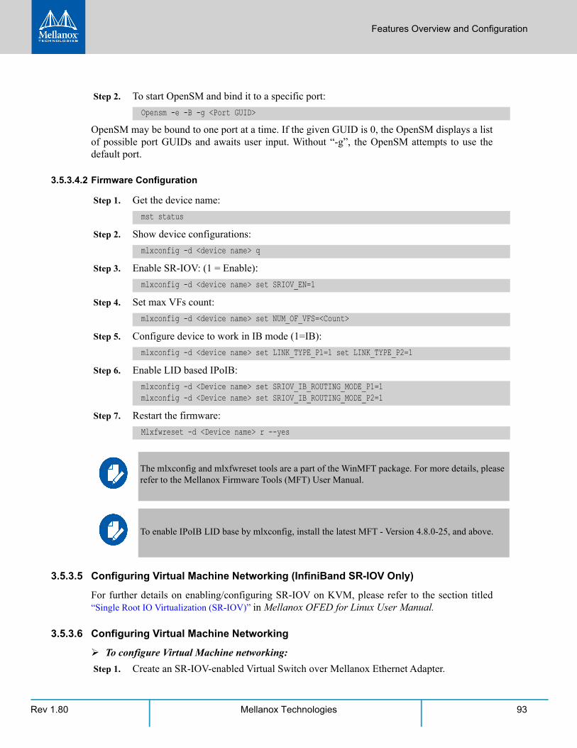
Features Overview and Configuration
Rev 1.80 93Mellanox Technologies
Step 2. To start OpenSM and bind it to a specific port:
OpenSM may be bound to one port at a time. If the given GUID is 0, the OpenSM displays a list of possible port GUIDs and awaits user input. Without “-g”, the OpenSM attempts to use the default port.
3.5.3.4.2 Firmware Configuration
Step 1. Get the device name:
Step 2. Show device configurations:
Step 3. Enable SR-IOV: (1 = Enable):
Step 4. Set max VFs count:
Step 5. Configure device to work in IB mode (1=IB):
Step 6. Enable LID based IPoIB:
Step 7. Restart the firmware:
3.5.3.5 Configuring Virtual Machine Networking (InfiniBand SR-IOV Only)
For further details on enabling/configuring SR-IOV on KVM, please refer to the section titled “Single Root IO Virtualization (SR-IOV)” in Mellanox OFED for Linux User Manual.
3.5.3.6 Configuring Virtual Machine Networking
To configure Virtual Machine networking:
Step 1. Create an SR-IOV-enabled Virtual Switch over Mellanox Ethernet Adapter.
Opensm -e -B -g <Port GUID>
mst status
mlxconfig -d <device name> q
mlxconfig -d <device name> set SRIOV_EN=1
mlxconfig -d <device name> set NUM_OF_VFS=<Count>
mlxconfig -d <device name> set LINK_TYPE_P1=1 set LINK_TYPE_P2=1
mlxconfig -d <Device name> set SRIOV_IB_ROUTING_MODE_P1=1 mlxconfig -d <Device name> set SRIOV_IB_ROUTING_MODE_P2=1
Mlxfwreset -d <Device name> r --yes
The mlxconfig and mlxfwreset tools are a part of the WinMFT package. For more details, please refer to the Mellanox Firmware Tools (MFT) User Manual.
To enable IPoIB LID base by mlxconfig, install the latest MFT - Version 4.8.0-25, and above.
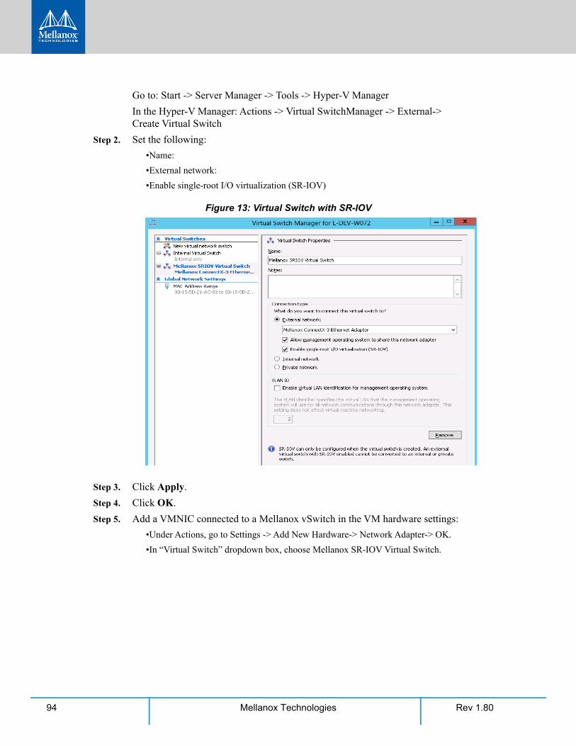
Rev 1.8094 Mellanox Technologies
Go to: Start -> Server Manager -> Tools -> Hyper-V Manager
In the Hyper-V Manager: Actions -> Virtual SwitchManager -> External-> Create Virtual Switch
Step 2. Set the following:
•Name:
•External network:
•Enable single-root I/O virtualization (SR-IOV)
Figure 13: Virtual Switch with SR-IOV
Step 3. Click Apply.
Step 4. Click OK.
Step 5. Add a VMNIC connected to a Mellanox vSwitch in the VM hardware settings:
•Under Actions, go to Settings -> Add New Hardware-> Network Adapter-> OK.
•In “Virtual Switch” dropdown box, choose Mellanox SR-IOV Virtual Switch.
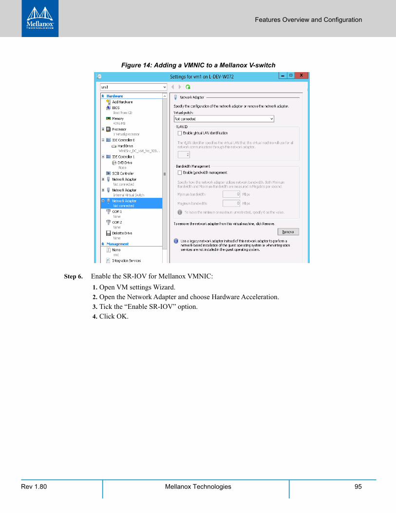
Features Overview and Configuration
Rev 1.80 95Mellanox Technologies
Figure 14: Adding a VMNIC to a Mellanox V-switch
Step 6. Enable the SR-IOV for Mellanox VMNIC:
1. Open VM settings Wizard. 2. Open the Network Adapter and choose Hardware Acceleration. 3. Tick the “Enable SR-IOV” option. 4. Click OK.
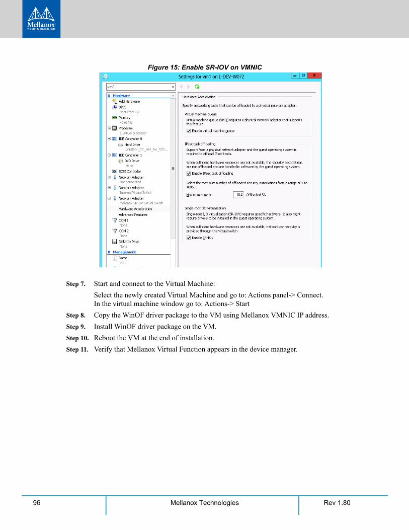
Rev 1.8096 Mellanox Technologies
Figure 15: Enable SR-IOV on VMNIC
Step 7. Start and connect to the Virtual Machine:
Select the newly created Virtual Machine and go to: Actions panel-> Connect. In the virtual machine window go to: Actions-> Start
Step 8. Copy the WinOF driver package to the VM using Mellanox VMNIC IP address.
Step 9. Install WinOF driver package on the VM.
Step 10. Reboot the VM at the end of installation.
Step 11. Verify that Mellanox Virtual Function appears in the device manager.

Features Overview and Configuration
Rev 1.80 97Mellanox Technologies
Figure 16: Virtual Function in the VM
3.5.3.7 VF Spoof Protection
WinOF-2 supports two levels of spoof protection:
• Hypervisor sets VF's MAC address and only packets with that MAC can be transmitted by the VF
• Hypervisor can control allowed Ethertypes that the VF can transmit
If a VF attempts to transmit packets with undesired source MAC or Ethertype, the packets will be dropped by an internal e-Switch. By default, the anti-spoof filter is enabled with the following Ethertypes:
• Internet Protocol version 4 (IPv4) (0x0800)
• Internet Protocol Version 6 (IPv6) (0x86DD)
• Address Resolution Protocol (ARP) (0x0806)
To achieve best performance on SR-IOV VF, please run the following powershell com-mands on the host:
For 10Gbe:
PS $ Set-VMNetworkAdapter -Name "Network Adapter" -VMName vm1 -IovQueue-PairsRequested 4
For 40Gbe and 56Gbe:
PS $ Set-VMNetworkAdapter -Name "Network Adapter" -VMName vm1 -IovQueue-PairsRequested 8
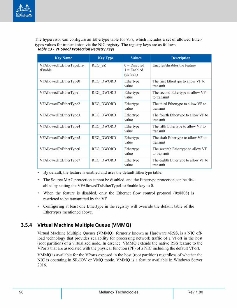
Rev 1.8098 Mellanox Technologies
The hypervisor can configure an Ethertype table for VFs, which includes a set of allowed Ether-types values for transmission via the NIC registry. The registry keys are as follows:
• By default, the feature is enabled and uses the default Ethertype table.
• The Source MAC protection cannot be disabled, and the Ethertype protection can be dis-abled by setting the VFAllowedTxEtherTypeListEnable key to 0.
• When the feature is disabled, only the Ethernet flow control protocol (0x8808) is restricted to be transmitted by the VF.
• Configuring at least one Ethertype in the registry will override the default table of the Ethertypes mentioned above.
3.5.4 Virtual Machine Multiple Queue (VMMQ)Virtual Machine Multiple Queues (VMMQ), formerly known as Hardware vRSS, is a NIC off-load technology that provides scalability for processing network traffic of a VPort in the host (root partition) of a virtualized node. In essence, VMMQ extends the native RSS feature to the VPorts that are associated with the physical function (PF) of a NIC including the default VPort.
VMMQ is available for the VPorts exposed in the host (root partition) regardless of whether the NIC is operating in SR-IOV or VMQ mode. VMMQ is a feature available in Windows Server 2016.
Table 13 - VF Spoof Protection Registry Keys
Key Name Key Type Values Description
VFAllowedTxEtherTypeLis-tEnable
REG_SZ 0 = Disabled1 = Enabled (default)
Enables/disables the feature
VFAllowedTxEtherType0 REG_DWORD Ethertype value
The first Ethertype to allow VF to transmit
VFAllowedTxEtherType1 REG_DWORD Ethertype value
The second Ethertype to allow VF to transmit
VFAllowedTxEtherType2 REG_DWORD Ethertype value
The third Ethertype to allow VF to transmit
VFAllowedTxEtherType3 REG_DWORD Ethertype value
The fourth Ethertype to allow VF to transmit
VFAllowedTxEtherType4 REG_DWORD Ethertype value
The fifth Ethertype to allow VF to transmit
VFAllowedTxEtherType5 REG_DWORD Ethertype value
The sixth Ethertype to allow VF to transmit
VFAllowedTxEtherType6 REG_DWORD Ethertype value
The seventh Ethertype to allow VF to transmit
VFAllowedTxEtherType7 REG_DWORD Ethertype value
The eighth Ethertype to allow VF to transmit
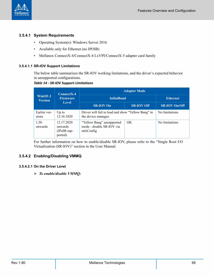
Features Overview and Configuration
Rev 1.80 99Mellanox Technologies
3.5.4.1 System Requirements
• Operating System(s): Windows Server 2016
• Available only for Ethernet (no IPOIB)
• Mellanox ConnectX-4/ConnectX-4 LxVPI/ConnectX-5 adapter card family
3.5.4.1.1 SR-IOV Support Limitations
The below table summarizes the SR-IOV working limitations, and the driver’s expected behavior in unsupported configurations.
For further information on how to enable/disable SR-IOV, please refer to the “Single Root I/O Virtualization (SR-IOV)” section in the User Manual.
3.5.4.2 Enabling/Disabling VMMQ
3.5.4.2.1 On the Driver Level
To enable/disable VMMQ:
Table 14 - SR-IOV Support Limitations
WinOF-2 Version
ConnectX-4 Firmware
Level
Adapter Mode
InfiniBand Ethernet
SR-IOV On SR-IOV Off SR-IOV On/Off
Earlier ver-sions
Up to 12.16.1020
Driver will fail to load and show "Yellow Bang" in the device manager.
No limitations
1.50 onwards
12.17.2020 onwards (IPoIB sup-ported)
“Yellow Bang” unsupported mode - disable SR-IOV via mlxConfig
OK No limitations
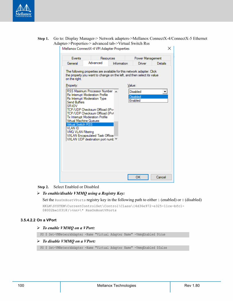
Rev 1.80100 Mellanox Technologies
Step 1. Go to: Display Manager-> Network adapters->Mellanox ConnectX-4/ConnectX-5 Ethernet Adapter->Properties-> advanced tab->Virtual Switch Rss
Step 2. Select Enabled or Disabled
To enable/disable VMMQ using a Registry Key:
Set the RssOnHostVPorts registry key in the following path to either 1 (enabled) or 0 (disabled)
HKLM\SYSTEM\CurrentControlSet\Control\Class\{4d36e972-e325-11ce-bfc1-08002be10318}\<nn>\* RssOnHostVPorts
3.5.4.2.2 On a VPort
To enable VMMQ on a VPort:
To disable VMMQ on a VPort:
PS $ Set-VMNetworkAdapter -Name "Virtual Adapter Name" -VmmqEnabled $true
PS $ Set-VMNetworkAdapter -Name "Virtual Adapter Name" -VmmqEnabled $false
Features Overview and Configuration
Rev 1.80 101Mellanox Technologies
3.5.4.3 Controlling the Number of Queues Allocated for a vPort
The requested number of queues for a virtual network adapter (vPort) can be set by invoking this PS cmdlet:
3.5.5 Network Direct Kernel Provider InterfaceAs of v1.45, WinOF-2 supports NDIS Network Direct Kernel Provider Interface version 2. The Network Direct Kernel Provider Interface (NDKPI) is an extension to NDIS that allows IHVs to provide kernel-mode Remote Direct Memory Access (RDMA) support in a network adapter.
3.5.5.1 System Requirement
• Operating System: Windows Server 2012 R2 (Without NDK from/to a VM) and Win-dows 2016
3.5.5.2 Configuring NDK
3.5.5.2.1 General Configurations
Step 1. Make sure the port is configured as Ethernet.
Step 2. Make sure the RoCE mode is configured the same on both ends, run “mlx5cmd -stat” from the "Command Prompt". ROCE v2 is the default mode.
3.5.5.2.2 Configuring NDK for Virtual NICs
Step 1. Create a VMSwitch.
Step 2. Create the virtual network adapters.
Since the VMMQ is an offload feature for vRss, vRss must be enabled prior to enabling VMMQ.
PS $ Set-VMNetworkAdapter -Name "VM Name" -name "Virtual Adapter Name" -VmmqQueuePairs <num-ber>
The number provided to this cmdlet is the requested number of queues per vPort. How-ever, the OS might decide to not fulfill the request due to some resources and other factors considerations.
PS $ New-VMSwitch -Name <vSwitchName> -NetAdapterName <EthInterfaceName> -AllowManage-mentOS $False
PS $ Add-VMNetworkAdapter -SwitchName <vSwitchName> -Name <EthInterfaceName> -Manage-mentOS
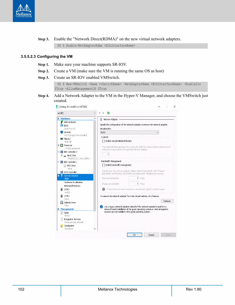
Rev 1.80102 Mellanox Technologies
Step 3. Enable the "Network Direct(RDMA)" on the new virtual network adapters.
3.5.5.2.3 Configuring the VM
Step 1. Make sure your machine supports SR-IOV.
Step 2. Create a VM (make sure the VM is running the same OS as host)
Step 3. Create an SR-IOV enabled VMSwitch.
Step 4. Add a Network Adapter to the VM in the Hyper-V Manager, and choose the VMSwitch just created.
PS $ Enable-NetAdapterRdma <EthInterfaceName>
PS $ New-VMSwitch -Name <vSwitchName> -NetAdapterName <EthInterfaceName> -EnableIov $True -AllowManagementOS $True
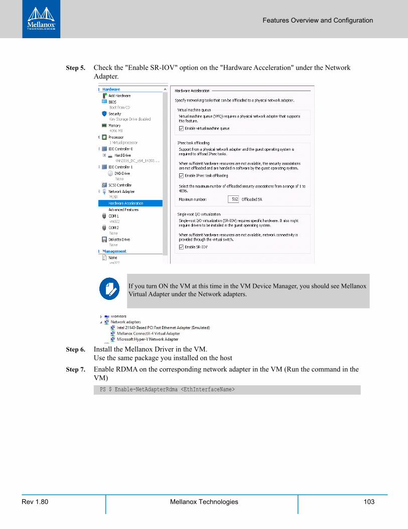
Features Overview and Configuration
Rev 1.80 103Mellanox Technologies
Step 5. Check the "Enable SR-IOV" option on the "Hardware Acceleration" under the Network Adapter.
Step 6. Install the Mellanox Driver in the VM. Use the same package you installed on the host
Step 7. Enable RDMA on the corresponding network adapter in the VM (Run the command in the VM)
If you turn ON the VM at this time in the VM Device Manager, you should see Mellanox Virtual Adapter under the Network adapters.
PS $ Enable-NetAdapterRdma <EthInterfaceName>
Rev 1.80104 Mellanox Technologies
3.5.5.2.4 Configuring Guest RDMA for Windows Server Version 1709 (Beta)
Step 1. To configure Guest RDMA for Windows Server Version 1709, keep the VM up and run-ning, and run the following command on the host:
Options:
Step 2. To query whether a specific VM has RDMA capability, run the following command:
3.5.5.3 Utility to Run and Monitor NDK
3.5.5.3.1 Running NDK
Since SMB is NDK’s client, it should be used to generate traffic. To generate traffic, do a big copy from one machine to the other.
For instance, use "xcopy" to recursively copy the entire c:\Windows directory or from a "Com-mand Prompt" window, run:
For example:
The following is applicable to Windows Server 2016 RS2 and above.
Before attending to the below steps, accomplish the configuration detailed in 3.5.5.2.3 “Configuring the VM,” on page 102.
Set-VMNetworkAdapter -VMName <VM name> -IovWeight 0Set-VMNetworkAdapterRdma -VMName <VM name> -RdmaWeight <0 | 100>Set-VMNetworkAdapter -VMName <VM name> -IovWeight 100
Value Usage
IovWeight VF allocation
0 Detach the VF
100 Attach the VF
RdmaWeight RDMA capability
0 Disable RDMA for this specific VM
100 Enable RDMA for this specific VM
Get-VMNetworkAdapterRdma -VMName <VM name>
Any non-zero value for the RdmaWeight field indicates that RDMA capability is true for this VM.
xcopy /s c:\Windows \\<remote machine ip>\<remote machine directory for receiving>
xcopy /s c:\Windows \\11.0.0.5\c$\tmp
Features Overview and Configuration
Rev 1.80 105Mellanox Technologies
3.5.5.3.2 Validating NDK
During the run time of NDK test (xcopy), with "RDMA Activity" in the perfmon.
Use the mlx5cmd sniffer to see the protocol information of the traffic packet.
3.5.6 PacketDirect Provider InterfaceAs of v1.45, WinOF-2 supports NDIS PacketDirect Provider Interface. PacketDirect extends NDIS with an accelerated I/O model, which can increase the number of packets processed per second by an order of magnitude and significantly decrease jitter when compared to the tradi-tional NDIS I/O path.
3.5.6.1 System Requirements
• Hypervisor OS: Windows Server 2016
• Available only for Ethernet (no IPOIB)
• Virtual Machine (VM) OS: Windows Server 2012 and above
• Mellanox ConnectX-4/ConnectX-4 Lx/ConnectX-5/ConnectX-5 Ex
• Mellanox WinOF-2 1.45 or higher
• Firmware version: 12.16.1020/14.16.1020 or higher
3.5.6.2 Using PacketDirect for VM
To allow a VM to send/receive traffic in PacketDirect mode:
Step 1. Enable PacketDirect:
•On the Ethernet adapter.
PacketDirect is supported only on Ethernet ports.
PS $ Enable-NetAdapterPacketDirect -Name <EthInterfaceName>

Rev 1.80106 Mellanox Technologies
•In the Device Manager.
Step 2. Create a vSwitch with PacketDirect enabled.
Step 3. Enable VFP extension:
• On the vSwitch.
PS $ New-VMSwitch <vSwitchName> -NetAdapterName <EthInterfaceName> -EnablePacketDirect $true -AllowManagementOS $true
PS $ Enable-VMSwitchExtension -VmSwitchName <vSwitchName> -Name "Windows Azure VFP Switch Extension"
Starting from Windows Server 2016, to enable the VFP extension, use the following command instead: Enable-VMSwitchExtension -VmSwitchName <vSwitchName> -Name "Microsoft Azure VFP Switch Extension"
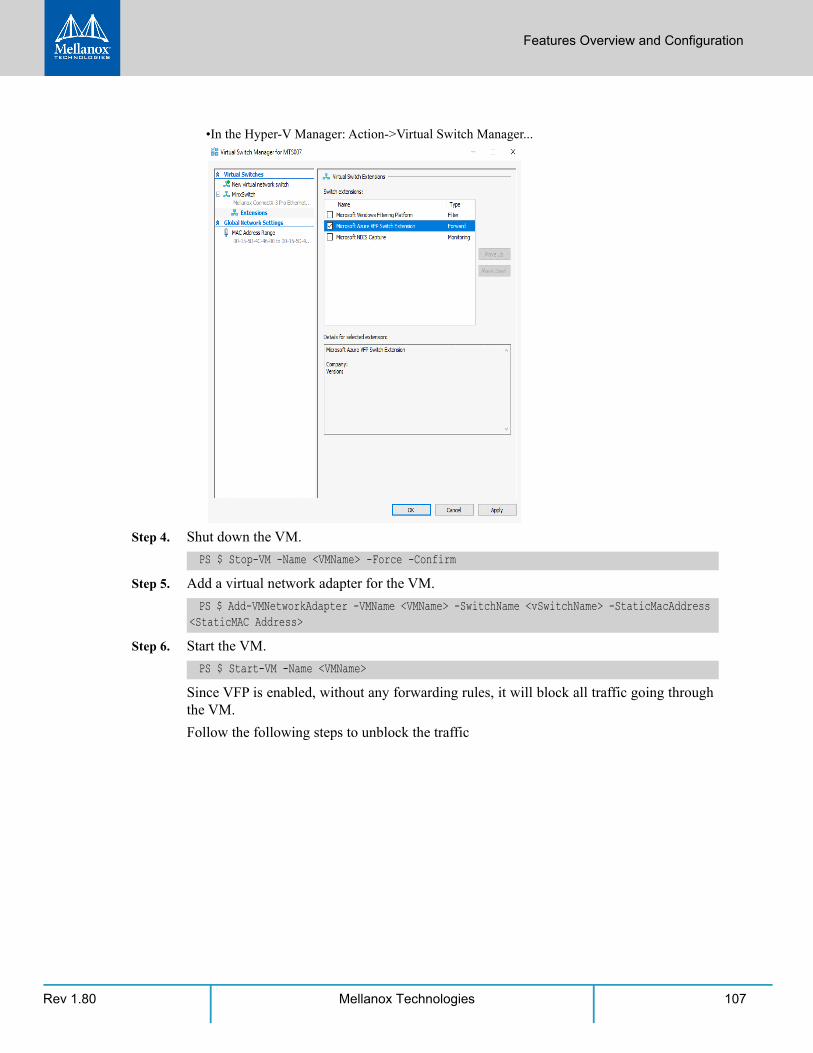
Features Overview and Configuration
Rev 1.80 107Mellanox Technologies
•In the Hyper-V Manager: Action->Virtual Switch Manager...
Step 4. Shut down the VM.
Step 5. Add a virtual network adapter for the VM.
Step 6. Start the VM.
Since VFP is enabled, without any forwarding rules, it will block all traffic going through the VM.
Follow the following steps to unblock the traffic
PS $ Stop-VM -Name <VMName> -Force -Confirm
PS $ Add-VMNetworkAdapter -VMName <VMName> -SwitchName <vSwitchName> -StaticMacAddress <StaticMAC Address>
PS $ Start-VM -Name <VMName>
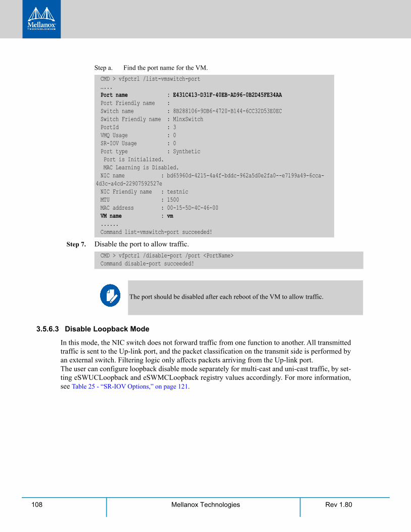
Rev 1.80108 Mellanox Technologies
Step a. Find the port name for the VM.
Step 7. Disable the port to allow traffic.
3.5.6.3 Disable Loopback Mode
In this mode, the NIC switch does not forward traffic from one function to another. All transmitted traffic is sent to the Up-link port, and the packet classification on the transmit side is performed by an external switch. Filtering logic only affects packets arriving from the Up-link port.The user can configure loopback disable mode separately for multi-cast and uni-cast traffic, by set-ting eSWUCLoopback and eSWMCLoopback registry values accordingly. For more information, see Table 25 - “SR-IOV Options,” on page 121.
CMD > vfpctrl /list-vmswitch-port…...Port name : E431C413-D31F-40EB-AD96-0B2D45FE34AAPort Friendly name :Switch name : 8B288106-9DB6-4720-B144-6CC32D53E0ECSwitch Friendly name : MlnxSwitchPortId : 3VMQ Usage : 0SR-IOV Usage : 0Port type : Synthetic Port is Initialized. MAC Learning is Disabled.NIC name : bd65960d-4215-4a4f-bddc-962a5d0e2fa0--e7199a49-6cca-
4d3c-a4cd-22907592527eNIC Friendly name : testnicMTU : 1500MAC address : 00-15-5D-4C-46-00VM name : vm......Command list-vmswitch-port succeeded!
CMD > vfpctrl /disable-port /port <PortName>Command disable-port succeeded!
The port should be disabled after each reboot of the VM to allow traffic.
Features Overview and Configuration
Rev 1.80 109Mellanox Technologies
3.5.7 Data Plane Development Kit (DPDK)
3.5.7.1 General Background and References
DPDK is a set of libraries and optimized NIC drivers for fast packet processing in user space. It provides a framework and common API for high speed networking applications.
• The WinOF driver supports running DPDK from an SR-IOV virtual machine. See 3.5.3
“Single Root I/O Virtualization (SR-IOV),” on page 81.
• It is recommended to browse Mellanox’s DPDK documentation:
• DPDK Quick Start Guide
• Mellanox DPDK Release Notes
3.5.7.2 Flows Prerequisites
• The DPDK flows must have a valid source MAC.
• The flows’ VLAN is determined by the Hyper-V.
3.6 Configuring the Driver Registry KeysMellanox IPoIB and Ethernet drivers use registry keys to control the NIC operations. The regis-try keys receive default values during the installation of the Mellanox adapters. Most of the parameters are visible in the registry by default, however, certain parameters must be created in order to modify the default behavior of the Mellanox driver.
The adapter can be configured either from the User Interface (Device Manager -> Mellanox Adapter -> Right click -> Properties) or by setting the registry directly.
All Mellanox adapter parameters are located in the registry under the following registry key:
The registry key can be divided into 4 different groups:
DPDK is currently at a Beta level.
HKEY_LOCAL_MACHINE\SYSTEM\CurrentControlSet\ Control\ Class\{4D36E972-E325-11CE-BFC1-08002bE10318}\<Index>
Table 15 - Registry Key Groups
Group Description
Basic Contains the basic configuration.
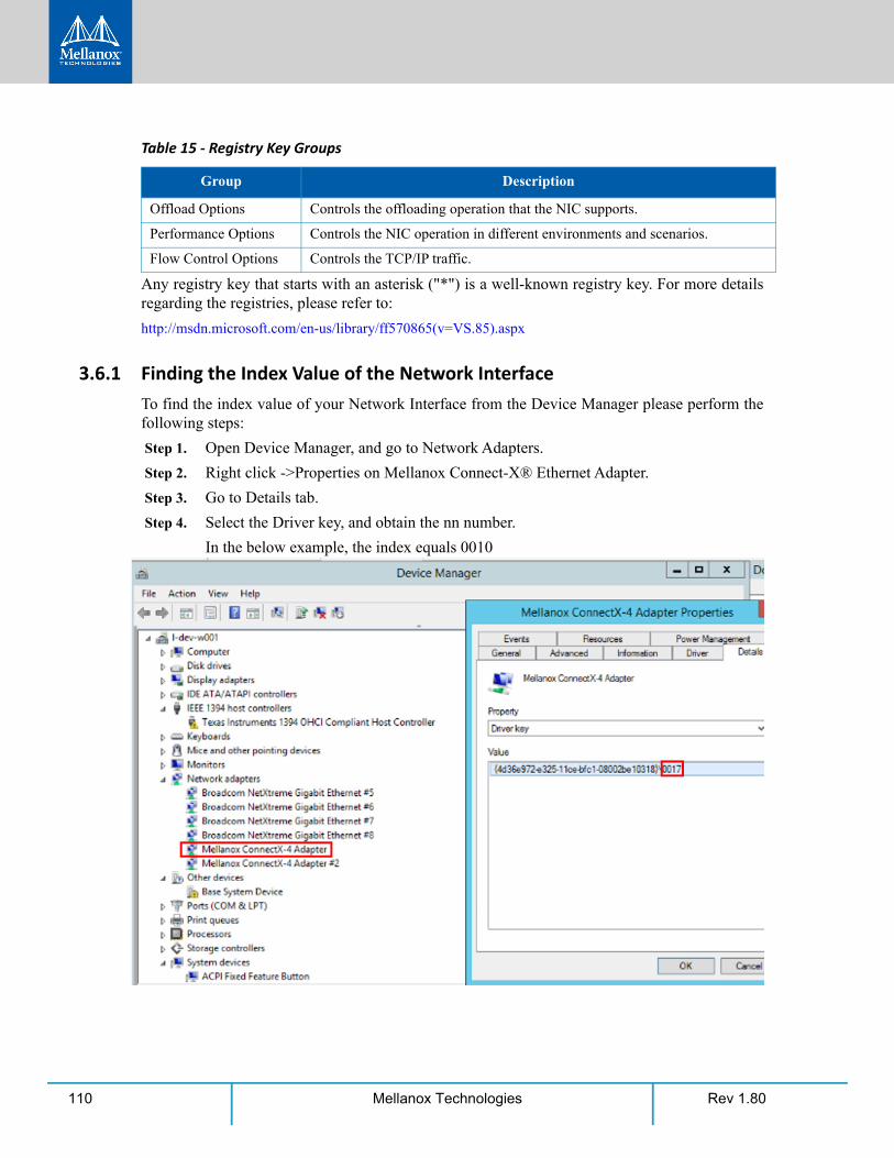
Rev 1.80110 Mellanox Technologies
Any registry key that starts with an asterisk ("*") is a well-known registry key. For more details regarding the registries, please refer to:
http://msdn.microsoft.com/en-us/library/ff570865(v=VS.85).aspx
3.6.1 Finding the Index Value of the Network InterfaceTo find the index value of your Network Interface from the Device Manager please perform the following steps:
Step 1. Open Device Manager, and go to Network Adapters.
Step 2. Right click ->Properties on Mellanox Connect-X® Ethernet Adapter.
Step 3. Go to Details tab.
Step 4. Select the Driver key, and obtain the nn number.
In the below example, the index equals 0010
Offload Options Controls the offloading operation that the NIC supports.
Performance Options Controls the NIC operation in different environments and scenarios.
Flow Control Options Controls the TCP/IP traffic.
Table 15 - Registry Key Groups
Group Description

Features Overview and Configuration
Rev 1.80 111Mellanox Technologies
3.6.2 Basic Registry KeysThis group contains the registry keys that control the basic operations of the NIC
All registry keys added for driver configuration should be of string type (REG_SZ).
After setting a registry key and re-loading the driver, you may use the mlx5cmd -regkeys command to assure that the value was read by the driver.
Table 16 - Basic Registry Keys
Value Name Default Value Description
*JumboPacket ETH: 1514IPoIB: 4092
The maximum size of a frame (or a packet) that can be sent over the wire. This is also known as the maximum trans-mission unit (MTU). The MTU may have a significant impact on the network's performance as a large packet can cause high latency. However, it can also reduce the CPU utilization and improve the wire efficiency. The standard Ethernet frame size is 1514 bytes, but Mellanox drivers support wide range of packet sizes.The valid values are:• Ethernet: 600 up to 9600• IPoIB: 256 up to 4092
Note: All the devices across the network (switches and routers) should support the same frame size. Be aware that different network devices calculate the frame size differ-ently. Some devices include the header, i.e. information in the frame size, while others do not.Mellanox adapters do not include Ethernet header informa-tion in the frame size. (i.e when setting *JumboPacket to 1500, the actual frame size is 1514).
*ReceiveBuffers 512 The number of packets each ring receives. This parameter affects the memory consumption and the performance. Increasing this value can enhance receive performance, but also consumes more system memory. In case of lack of received buffers (dropped packets or out of order received packets), you can increase the number of received buffers. The valid values are 256 up to 4096.
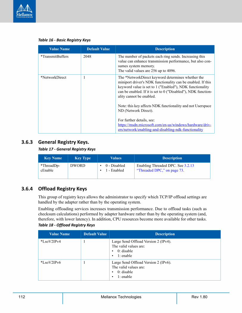
Rev 1.80112 Mellanox Technologies
3.6.3 General Registry Keys.
3.6.4 Offload Registry KeysThis group of registry keys allows the administrator to specify which TCP/IP offload settings are handled by the adapter rather than by the operating system.
Enabling offloading services increases transmission performance. Due to offload tasks (such as checksum calculations) performed by adapter hardware rather than by the operating system (and, therefore, with lower latency). In addition, CPU resources become more available for other tasks.
*TransmitBuffers 2048 The number of packets each ring sends. Increasing this value can enhance transmission performance, but also con-sumes system memory. The valid values are 256 up to 4096.
*NetworkDirect 1 The *NetworkDirect keyword determines whether the miniport driver's NDK functionality can be enabled. If this keyword value is set to 1 ("Enabled"), NDK functionality can be enabled. If it is set to 0 ("Disabled"), NDK function-ality cannot be enabled.
Note: this key affects NDK functionality and not Userspace ND (Network Direct).
For further details, see:https://msdn.microsoft.com/en-us/windows/hardware/driv-ers/network/enabling-and-disabling-ndk-functionality
Table 17 - General Registry Keys
Key Name Key Type Values Description
*ThreadDp-cEnable
DWORD • 0 - Disabled• 1 - Enabled
Enabling Threaded DPC. See 3.2.13 “Threaded DPC,” on page 73.
Table 18 - Offload Registry Keys
Value Name Default Value Description
*LsoV2IPv4 1 Large Send Offload Version 2 (IPv4).The valid values are:• 0: disable• 1: enable
*LsoV2IPv6 1 Large Send Offload Version 2 (IPv6).The valid values are:• 0: disable• 1: enable
Table 16 - Basic Registry Keys
Value Name Default Value Description
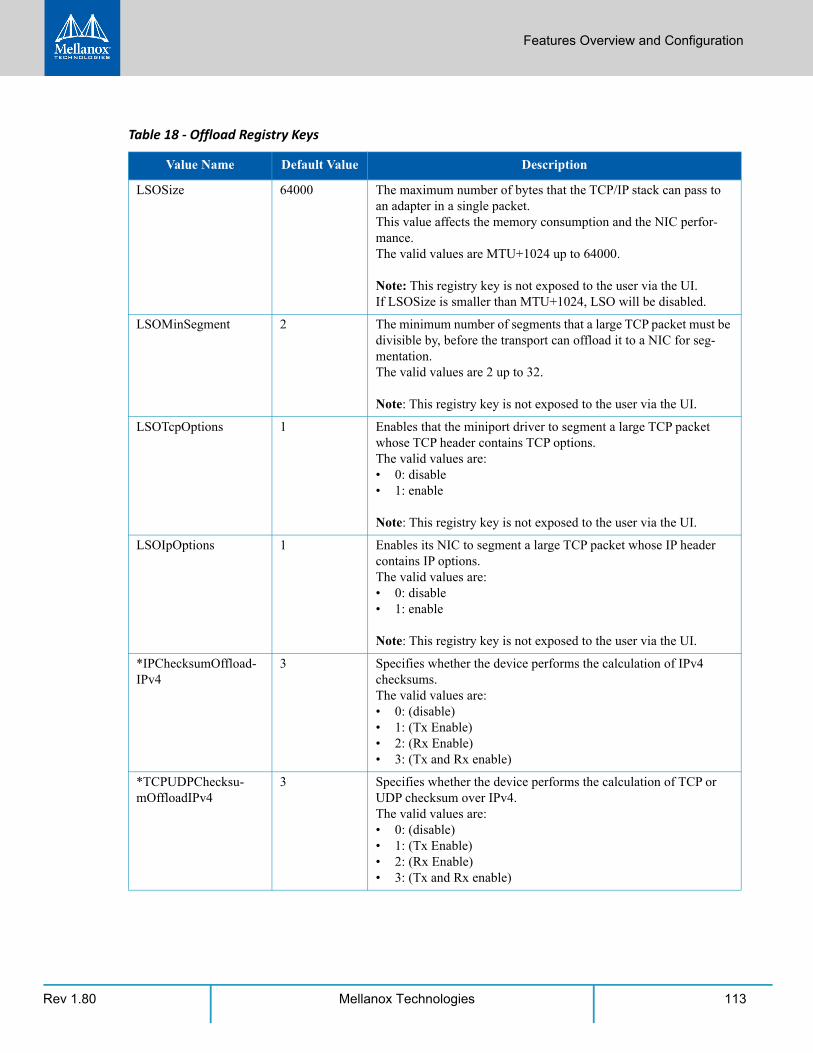
Features Overview and Configuration
Rev 1.80 113Mellanox Technologies
LSOSize 64000 The maximum number of bytes that the TCP/IP stack can pass to an adapter in a single packet. This value affects the memory consumption and the NIC perfor-mance.The valid values are MTU+1024 up to 64000.
Note: This registry key is not exposed to the user via the UI.If LSOSize is smaller than MTU+1024, LSO will be disabled.
LSOMinSegment 2 The minimum number of segments that a large TCP packet must be divisible by, before the transport can offload it to a NIC for seg-mentation.The valid values are 2 up to 32.
Note: This registry key is not exposed to the user via the UI.
LSOTcpOptions 1 Enables that the miniport driver to segment a large TCP packet whose TCP header contains TCP options.The valid values are:• 0: disable• 1: enable
Note: This registry key is not exposed to the user via the UI.
LSOIpOptions 1 Enables its NIC to segment a large TCP packet whose IP header contains IP options.The valid values are:• 0: disable• 1: enable
Note: This registry key is not exposed to the user via the UI.
*IPChecksumOffload-IPv4
3 Specifies whether the device performs the calculation of IPv4 checksums.The valid values are:• 0: (disable)• 1: (Tx Enable)• 2: (Rx Enable)• 3: (Tx and Rx enable)
*TCPUDPChecksu-mOffloadIPv4
3 Specifies whether the device performs the calculation of TCP or UDP checksum over IPv4.The valid values are:• 0: (disable)• 1: (Tx Enable)• 2: (Rx Enable)• 3: (Tx and Rx enable)
Table 18 - Offload Registry Keys
Value Name Default Value Description
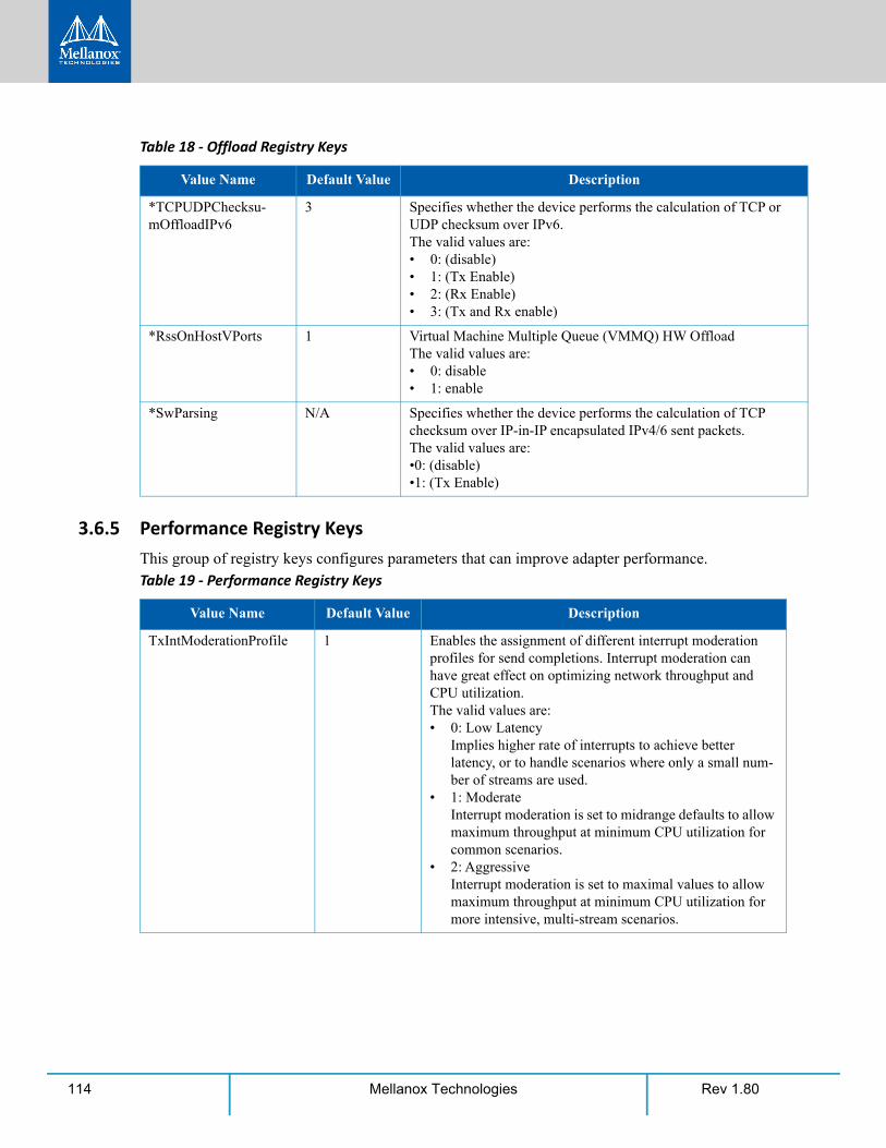
Rev 1.80114 Mellanox Technologies
3.6.5 Performance Registry KeysThis group of registry keys configures parameters that can improve adapter performance.
*TCPUDPChecksu-mOffloadIPv6
3 Specifies whether the device performs the calculation of TCP or UDP checksum over IPv6.The valid values are:• 0: (disable)• 1: (Tx Enable)• 2: (Rx Enable)• 3: (Tx and Rx enable)
*RssOnHostVPorts 1 Virtual Machine Multiple Queue (VMMQ) HW OffloadThe valid values are:• 0: disable• 1: enable
*SwParsing N/A Specifies whether the device performs the calculation of TCP checksum over IP-in-IP encapsulated IPv4/6 sent packets.The valid values are:•0: (disable)•1: (Tx Enable)
Table 19 - Performance Registry Keys
Value Name Default Value Description
TxIntModerationProfile 1 Enables the assignment of different interrupt moderation profiles for send completions. Interrupt moderation can have great effect on optimizing network throughput and CPU utilization.The valid values are:• 0: Low Latency
Implies higher rate of interrupts to achieve better latency, or to handle scenarios where only a small num-ber of streams are used.
• 1: ModerateInterrupt moderation is set to midrange defaults to allow maximum throughput at minimum CPU utilization for common scenarios.
• 2: AggressiveInterrupt moderation is set to maximal values to allow maximum throughput at minimum CPU utilization for more intensive, multi-stream scenarios.
Table 18 - Offload Registry Keys
Value Name Default Value Description
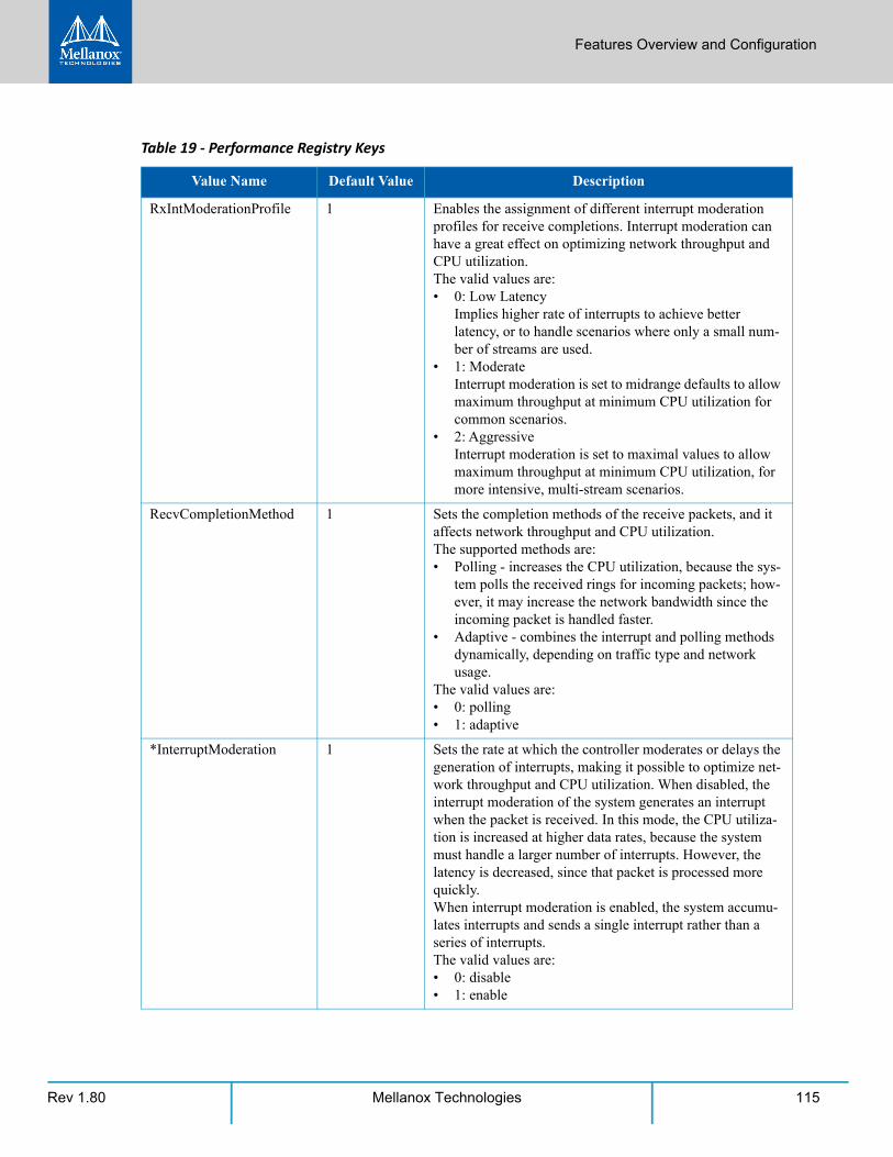
Features Overview and Configuration
Rev 1.80 115Mellanox Technologies
RxIntModerationProfile 1 Enables the assignment of different interrupt moderation profiles for receive completions. Interrupt moderation can have a great effect on optimizing network throughput and CPU utilization.The valid values are:• 0: Low Latency
Implies higher rate of interrupts to achieve better latency, or to handle scenarios where only a small num-ber of streams are used.
• 1: ModerateInterrupt moderation is set to midrange defaults to allow maximum throughput at minimum CPU utilization for common scenarios.
• 2: AggressiveInterrupt moderation is set to maximal values to allow maximum throughput at minimum CPU utilization, for more intensive, multi-stream scenarios.
RecvCompletionMethod 1 Sets the completion methods of the receive packets, and it affects network throughput and CPU utilization.The supported methods are:• Polling - increases the CPU utilization, because the sys-
tem polls the received rings for incoming packets; how-ever, it may increase the network bandwidth since the incoming packet is handled faster.
• Adaptive - combines the interrupt and polling methods dynamically, depending on traffic type and network usage.
The valid values are:• 0: polling• 1: adaptive
*InterruptModeration 1 Sets the rate at which the controller moderates or delays the generation of interrupts, making it possible to optimize net-work throughput and CPU utilization. When disabled, the interrupt moderation of the system generates an interrupt when the packet is received. In this mode, the CPU utiliza-tion is increased at higher data rates, because the system must handle a larger number of interrupts. However, the latency is decreased, since that packet is processed more quickly.When interrupt moderation is enabled, the system accumu-lates interrupts and sends a single interrupt rather than a series of interrupts. The valid values are:• 0: disable• 1: enable
Table 19 - Performance Registry Keys
Value Name Default Value Description
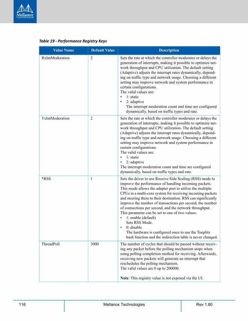
Rev 1.80116 Mellanox Technologies
RxIntModeration 2 Sets the rate at which the controller moderates or delays the generation of interrupts, making it possible to optimize net-work throughput and CPU utilization. The default setting (Adaptive) adjusts the interrupt rates dynamically, depend-ing on traffic type and network usage. Choosing a different setting may improve network and system performance in certain configurations. The valid values are:• 1: static• 2: adaptive
The interrupt moderation count and time are configured dynamically, based on traffic types and rate.
TxIntModeration 2 Sets the rate at which the controller moderates or delays the generation of interrupts, making it possible to optimize net-work throughput and CPU utilization. The default setting (Adaptive) adjusts the interrupt rates dynamically, depend-ing on traffic type and network usage. Choosing a different setting may improve network and system performance in certain configurations. The valid values are:• 1: static• 2: adaptiveThe interrupt moderation count and time are configured dynamically, based on traffic types and rate.
*RSS 1 Sets the driver to use Receive Side Scaling (RSS) mode to improve the performance of handling incoming packets. This mode allows the adapter port to utilize the multiple CPUs in a multi-core system for receiving incoming packets and steering them to their destination. RSS can significantly improve the number of transactions per second, the number of connections per second, and the network throughput. This parameter can be set to one of two values:• 1: enable (default)
Sets RSS Mode.• 0: disable
The hardware is configured once to use the Toeplitz hash function and the indirection table is never changed.
ThreadPoll 3000 The number of cycles that should be passed without receiv-ing any packet before the polling mechanism stops when using polling completion method for receiving. Afterwards, receiving new packets will generate an interrupt that reschedules the polling mechanism. The valid values are 0 up to 200000.
Note: This registry value is not exposed via the UI.
Table 19 - Performance Registry Keys
Value Name Default Value Description
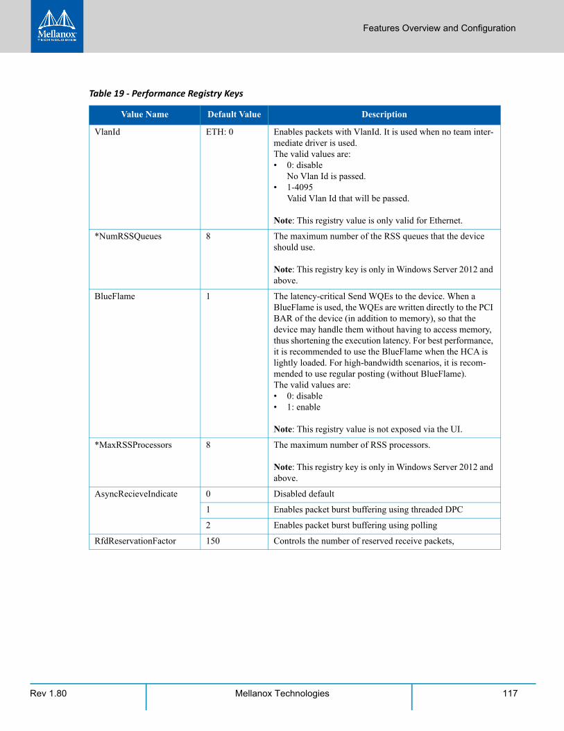
Features Overview and Configuration
Rev 1.80 117Mellanox Technologies
VlanId ETH: 0 Enables packets with VlanId. It is used when no team inter-mediate driver is used.The valid values are:• 0: disable
No Vlan Id is passed.• 1-4095
Valid Vlan Id that will be passed.
Note: This registry value is only valid for Ethernet.
*NumRSSQueues 8 The maximum number of the RSS queues that the device should use.
Note: This registry key is only in Windows Server 2012 and above.
BlueFlame 1 The latency-critical Send WQEs to the device. When a BlueFlame is used, the WQEs are written directly to the PCI BAR of the device (in addition to memory), so that the device may handle them without having to access memory, thus shortening the execution latency. For best performance, it is recommended to use the BlueFlame when the HCA is lightly loaded. For high-bandwidth scenarios, it is recom-mended to use regular posting (without BlueFlame).The valid values are:• 0: disable• 1: enable
Note: This registry value is not exposed via the UI.
*MaxRSSProcessors 8 The maximum number of RSS processors.
Note: This registry key is only in Windows Server 2012 and above.
AsyncRecieveIndicate 0 Disabled default
1 Enables packet burst buffering using threaded DPC
2 Enables packet burst buffering using polling
RfdReservationFactor 150 Controls the number of reserved receive packets,
Table 19 - Performance Registry Keys
Value Name Default Value Description
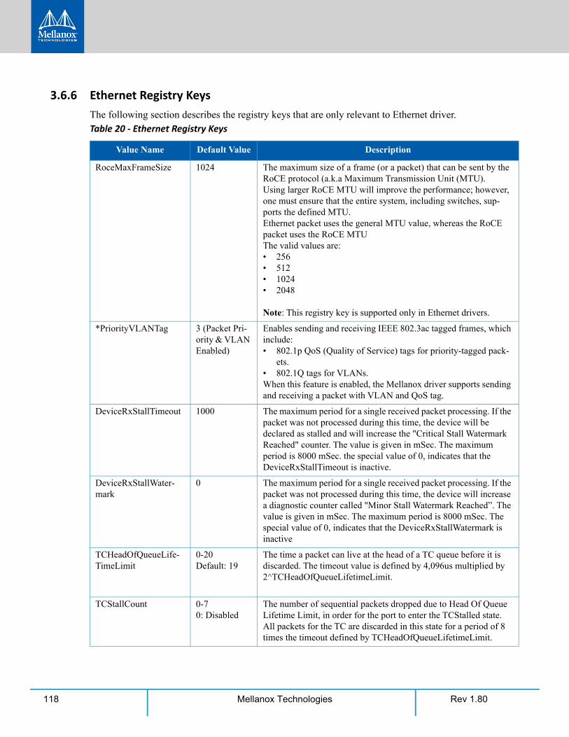
Rev 1.80118 Mellanox Technologies
3.6.6 Ethernet Registry KeysThe following section describes the registry keys that are only relevant to Ethernet driver.Table 20 - Ethernet Registry Keys
Value Name Default Value Description
RoceMaxFrameSize 1024 The maximum size of a frame (or a packet) that can be sent by the RoCE protocol (a.k.a Maximum Transmission Unit (MTU).Using larger RoCE MTU will improve the performance; however, one must ensure that the entire system, including switches, sup-ports the defined MTU.Ethernet packet uses the general MTU value, whereas the RoCE packet uses the RoCE MTUThe valid values are:• 256• 512• 1024 • 2048
Note: This registry key is supported only in Ethernet drivers.
*PriorityVLANTag 3 (Packet Pri-ority & VLAN Enabled)
Enables sending and receiving IEEE 802.3ac tagged frames, which include:• 802.1p QoS (Quality of Service) tags for priority-tagged pack-
ets.• 802.1Q tags for VLANs.When this feature is enabled, the Mellanox driver supports sending and receiving a packet with VLAN and QoS tag.
DeviceRxStallTimeout 1000 The maximum period for a single received packet processing. If the packet was not processed during this time, the device will be declared as stalled and will increase the "Critical Stall Watermark Reached" counter. The value is given in mSec. The maximum period is 8000 mSec. the special value of 0, indicates that the DeviceRxStallTimeout is inactive.
DeviceRxStallWater-mark
0 The maximum period for a single received packet processing. If the packet was not processed during this time, the device will increase a diagnostic counter called "Minor Stall Watermark Reached”. The value is given in mSec. The maximum period is 8000 mSec. The special value of 0, indicates that the DeviceRxStallWatermark is inactive
TCHeadOfQueueLife-TimeLimit
0-20Default: 19
The time a packet can live at the head of a TC queue before it is discarded. The timeout value is defined by 4,096us multiplied by 2^TCHeadOfQueueLifetimeLimit.
TCStallCount 0-70: Disabled
The number of sequential packets dropped due to Head Of Queue Lifetime Limit, in order for the port to enter the TCStalled state. All packets for the TC are discarded in this state for a period of 8 times the timeout defined by TCHeadOfQueueLifetimeLimit.
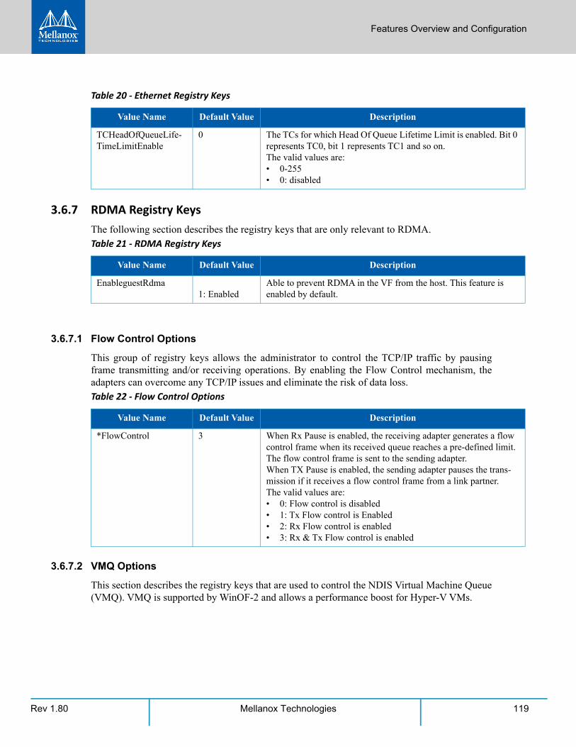
Features Overview and Configuration
Rev 1.80 119Mellanox Technologies
3.6.7 RDMA Registry KeysThe following section describes the registry keys that are only relevant to RDMA.
3.6.7.1 Flow Control Options
This group of registry keys allows the administrator to control the TCP/IP traffic by pausing frame transmitting and/or receiving operations. By enabling the Flow Control mechanism, the adapters can overcome any TCP/IP issues and eliminate the risk of data loss.
3.6.7.2 VMQ Options
This section describes the registry keys that are used to control the NDIS Virtual Machine Queue (VMQ). VMQ is supported by WinOF-2 and allows a performance boost for Hyper-V VMs.
TCHeadOfQueueLife-TimeLimitEnable
0 The TCs for which Head Of Queue Lifetime Limit is enabled. Bit 0 represents TC0, bit 1 represents TC1 and so on.The valid values are:• 0-255• 0: disabled
Table 21 - RDMA Registry Keys
Value Name Default Value Description
EnableguestRdma 1: Enabled
Able to prevent RDMA in the VF from the host. This feature is enabled by default.
Table 22 - Flow Control Options
Value Name Default Value Description
*FlowControl 3 When Rx Pause is enabled, the receiving adapter generates a flow control frame when its received queue reaches a pre-defined limit. The flow control frame is sent to the sending adapter.When TX Pause is enabled, the sending adapter pauses the trans-mission if it receives a flow control frame from a link partner.The valid values are:• 0: Flow control is disabled• 1: Tx Flow control is Enabled• 2: Rx Flow control is enabled• 3: Rx & Tx Flow control is enabled
Table 20 - Ethernet Registry Keys
Value Name Default Value Description
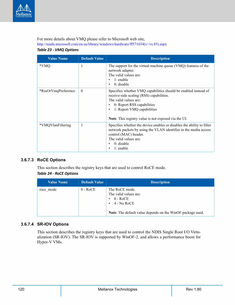
Rev 1.80120 Mellanox Technologies
For more details about VMQ please refer to Microsoft web site, http://msdn.microsoft.com/en-us/library/windows/hardware/ff571034(v=vs.85).aspx
3.6.7.3 RoCE Options
This section describes the registry keys that are used to control RoCE mode.
3.6.7.4 SR-IOV Options
This section describes the registry keys that are used to control the NDIS Single Root I/O Virtu-alization (SR-IOV). The SR-IOV is supported by WinOF-2, and allows a performance boost for Hyper-V VMs.
Table 23 - VMQ Options
Value Name Default Value Description
*VMQ 1 The support for the virtual machine queue (VMQ) features of the network adapter.The valid values are:• 1: enable• 0: disable
*RssOrVmqPreference 0 Specifies whether VMQ capabilities should be enabled instead of receive-side scaling (RSS) capabilities.The valid values are:• 0: Report RSS capabilities• 1: Report VMQ capabilities
Note: This registry value is not exposed via the UI.
*VMQVlanFiltering 1 Specifies whether the device enables or disables the ability to filter network packets by using the VLAN identifier in the media access control (MAC) header.The valid values are:• 0: disable• 1: enable
Table 24 - RoCE Options
Value Name Default Value Description
roce_mode 0 - RoCE The RoCE mode.The valid values are:• 0 - RoCE• 4 - No RoCE
Note: The default value depends on the WinOF package used.
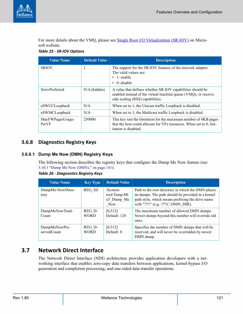
Features Overview and Configuration
Rev 1.80 121Mellanox Technologies
For more details about the VMQ, please see Single Root I/O Virtualization (SR-IOV) on Micro-soft website.
3.6.8 Diagnostics Registry Keys
3.6.8.1 Dump Me Now (DMN) Registry Keys
The following section describes the registry keys that configure the Dump Me Now feature (see 3.10.1 “Dump Me Now (DMN),” on page 141).
3.7 Network Direct InterfaceThe Network Direct Interface (NDI) architecture provides application developers with a net-working interface that enables zero-copy data transfers between applications, kernel-bypass I/O generation and completion processing, and one-sided data transfer operations.
Table 25 - SR-IOV Options
Value Name Default Value Description
SRIOV 1 The support for the SR-IOV features of the network adapter.The valid values are:• 1: enable
• 0: disable
SriovPreferred N/A (hidden) A value that defines whether SR-IOV capabilities should be enabled instead of the virtual machine queue (VMQ), or receive side scaling (RSS) capabilities.
eSWUCLoopback N/A When set to 1, the Unicast traffic Loopback is disabled.
eSWMCLoopback N/A When set to 1, the Multicast traffic Loopback is disabled.
MaxFWPagesUsage-PerVF
250000 This key sets the limitation for the maximum number of 4KB pages that the host could allocate for VFs resources. When set to 0, lim-itation is disabled.
Table 26 - Diagnostics Registry Keys
Value Name Key Type Default Value Description
DumpMe-NowDirec-tory
REG_SZ \System-root\Temp\Mlx5_Dump_Me_Now
Path to the root directory in which the DMN places its dumps. The path should be provided in a kernel path style, which means prefixing the drive name with "\??\" (e.g. \??\C:\DMN_DIR).
DumpMeNowTotal-Count
REG_D-WORD
[0,512]Default: 128
The maximum number of allowed DMN dumps. Newer dumps beyond this number will override old ones.
DumpMeNowPre-servedCount
REG_D-WORD
[0,512]Default: 8
Specifies the number of DMN dumps that will be reserved, and will never be overridden by newer DMN dump.
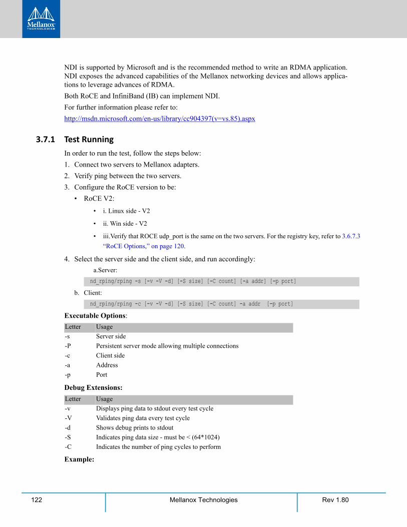
Rev 1.80122 Mellanox Technologies
NDI is supported by Microsoft and is the recommended method to write an RDMA application. NDI exposes the advanced capabilities of the Mellanox networking devices and allows applica-tions to leverage advances of RDMA.
Both RoCE and InfiniBand (IB) can implement NDI.
For further information please refer to:
http://msdn.microsoft.com/en-us/library/cc904397(v=vs.85).aspx
3.7.1 Test RunningIn order to run the test, follow the steps below:
1. Connect two servers to Mellanox adapters.
2. Verify ping between the two servers.
3. Configure the RoCE version to be:
• RoCE V2:
• i. Linux side - V2
• ii. Win side - V2
• iii.Verify that ROCE udp_port is the same on the two servers. For the registry key, refer to 3.6.7.3
“RoCE Options,” on page 120.
4. Select the server side and the client side, and run accordingly:
a.Server:
b. Client:
Executable Options:
Debug Extensions:
Example:
nd_rping/rping -s [-v -V -d] [-S size] [-C count] [-a addr] [-p port]
nd_rping/rping -c [-v -V -d] [-S size] [-C count] -a addr [-p port]
Letter Usage
-s Server side
-P Persistent server mode allowing multiple connections
-c Client side
-a Address
-p Port
Letter Usage
-v Displays ping data to stdout every test cycle
-V Validates ping data every test cycle
-d Shows debug prints to stdout
-S Indicates ping data size - must be < (64*1024)
-C Indicates the number of ping cycles to perform
Features Overview and Configuration
Rev 1.80 123Mellanox Technologies
Linux server:
Windows client:
The Network Direct Interface (NDI) architecture provides application developers with a net-working interface that enables zero-copy data transfers between applications, kernel-bypass I/O generation and completion processing, and one-sided data transfer operations.
NDI is supported by Microsoft and is the recommended method to write an RDMA application. NDI exposes the advanced capabilities of the Mellanox networking devices and allows applica-tions to leverage advances of RDMA.
Both RoCE and InfiniBand (IB) can implement NDI.
For further information please refer to:
http://msdn.microsoft.com/en-us/library/cc904397(v=vs.85).aspx
3.8 Performance TuningThis section describes how to modify Windows registry parameters in order to improve perfor-mance.
3.8.1 General Performance Optimization and TuningTo achieve the best performance for Windows, you may need to modify some of the Windows registries.
3.8.1.1 Registry Tuning
The registry entries that may be added/changed by this “General Tuning” procedure are:
Under HKEY_LOCAL_MACHINE\SYSTEM\CurrentControlSet\Services\Tcpip\Parameters:
• Disable TCP selective acks option for better cpu utilization:
Under HKEY_LOCAL_MACHINE\SYSTEM\CurrentControlSet\Services\AFD\Parameters:
• Enable fast datagram sending for UDP traffic:
Under HKEY_LOCAL_MACHINE\SYSTEM\CurrentControlSet\Services\Ndis\Parameters:
• Set RSS parameters:
rping -v -s -a <IP address> -C 10
nd_rping -v -c -a <same IP as above> -C 10
Please note that modifying the registry incorrectly might lead to serious problems, including the loss of data, system hang, and you may need to reinstall Windows. As such it is recommended to back up the registry on your system before implementing recommendations included in this sec-tion. If the modifications you apply lead to serious problems, you will be able to restore the original registry state. For more details about backing up and restoring the registry, please visit www.micro-soft.com.
SackOpts, type REG_DWORD, value set to 0.
FastSendDatagramThreshold, type REG_DWORD, value set to 64K.
RssBaseCpu, type REG_DWORD, value set to 1.
Rev 1.80124 Mellanox Technologies
3.8.1.2 Enable RSS
Enabling Receive Side Scaling (RSS) is performed by means of the following command:
3.8.1.3 Improving Live Migration
In order to improve live migration over SMB direct performance, please set the following regis-try key to 0 and reboot the machine:
3.8.2 Application Specific Optimization and Tuning
3.8.2.1 Ethernet Performance Tuning
The user can configure the Ethernet adapter by setting some registry keys. The registry keys may affect Ethernet performance.
To improve performance, activate the performance tuning tool as follows:
Step 1. Start the "Device Manager" (open a command line window and enter: devmgmt.msc).
Step 2. Open "Network Adapters".
Step 3. Right click the relevant Ethernet adapter and select Properties.
Step 4. Select the "Advanced" tab
Step 5. Modify performance parameters (properties) as desired.
3.8.2.1.1 Performance Known Issues
• On Intel I/OAT supported systems, it is highly recommended to install and enable the latest I/OAT driver (download from www.intel.com).
• With I/OAT enabled, sending 256-byte messages or larger will activate I/OAT. This will cause a significant latency increase due to I/OAT algorithms. On the other hand, throughput will increase significantly when using I/OAT.
3.8.2.2 Ethernet Bandwidth Improvements
To improve Ethernet Bandwidth:
Step 1. Check you are running on the closest NUMA.
“netsh int tcp set global rss = enabled”
HKEY_LOCAL_MACHINE\System\CurrentControlSet\Services\LanmanServer\Parameters\RequireSecuritySig-nature
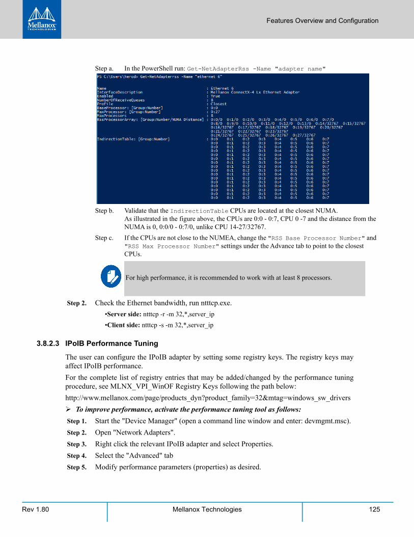
Features Overview and Configuration
Rev 1.80 125Mellanox Technologies
Step a. In the PowerShell run: Get-NetAdapterRss -Name "adapter name"
Step b. Validate that the IndirectionTable CPUs are located at the closest NUMA. As illustrated in the figure above, the CPUs are 0:0 - 0:7, CPU 0 -7 and the distance from the NUMA is 0, 0:0/0 - 0:7/0, unlike CPU 14-27/32767.
Step c. If the CPUs are not close to the NUMEA, change the "RSS Base Processor Number" and "RSS Max Processor Number" settings under the Advance tab to point to the closest CPUs.
Step 2. Check the Ethernet bandwidth, run ntttcp.exe.
•Server side: ntttcp -r -m 32,*,server_ip
•Client side: ntttcp -s -m 32,*,server_ip
3.8.2.3 IPoIB Performance Tuning
The user can configure the IPoIB adapter by setting some registry keys. The registry keys may affect IPoIB performance.
For the complete list of registry entries that may be added/changed by the performance tuning procedure, see MLNX_VPI_WinOF Registry Keys following the path below:
http://www.mellanox.com/page/products_dyn?product_family=32&mtag=windows_sw_drivers
To improve performance, activate the performance tuning tool as follows:
Step 1. Start the "Device Manager" (open a command line window and enter: devmgmt.msc).
Step 2. Open "Network Adapters".
Step 3. Right click the relevant IPoIB adapter and select Properties.
Step 4. Select the "Advanced" tab
Step 5. Modify performance parameters (properties) as desired.
For high performance, it is recommended to work with at least 8 processors.
Rev 1.80126 Mellanox Technologies
3.8.3 Tunable Performance ParametersThe following is a list of key parameters for performance tuning.
• Jumbo Packet
The maximum available size of the transfer unit, also known as the Maximum Transmission Unit (MTU). The MTU of a network can have a substantial impact on performance. A 4K MTU size improves performance for short messages, since it allows the OS to coalesce many small messages into a large one.
• Valid MTU values range for an Ethernet driver is between 614 and 9614.
• Receive Buffers
The number of receive buffers (default 512).
• Send Buffers
The number of sent buffers (default 2048).
• Performance Options
Configures parameters that can improve adapter performance.
• Interrupt Moderation
Moderates or delays the interrupts’ generation. Hence, optimizes network throughput and CPU uti-lization (default Enabled).
• When the interrupt moderation is enabled, the system accumulates interrupts and sends a single
interrupt rather than a series of interrupts. An interrupt is generated after receiving 5 packets or
after 10ms from the first packet received. It improves performance and reduces CPU load how-
ever, it increases latency.
• When the interrupt moderation is disabled, the system generates an interrupt each time a packet is
received or sent. In this mode, the CPU utilization data rates increase, as the system handles a
larger number of interrupts. However, the latency decreases as the packet is handled faster.
• Receive Side Scaling (RSS Mode)
Improves incoming packet processing performance. RSS enables the adapter port to utilize the multiple CPUs in a multi-core system for receiving incoming packets and steering them to the des-ignated destination. RSS can significantly improve the number of transactions, the number of con-nections per second, and the network throughput.
This parameter can be set to one of the following values:
• Enabled (default): Set RSS Mode
All devices on the same physical network, or on the same logical network, must have the same MTU.
Features Overview and Configuration
Rev 1.80 127Mellanox Technologies
• Disabled: The hardware is configured once to use the Toeplitz hash function, and the indirection
table is never changed.
• Receive Completion Method
Sets the completion methods of the received packets, and can affect network throughput and CPU utilization.
• Polling Method
Increases the CPU utilization as the system polls the received rings for the incoming packets. How-ever, it may increase the network performance as the incoming packet is handled faster.
• Adaptive (Default Settings)
A combination of the interrupt and polling methods dynamically, depending on traffic type and net-work usage. Choosing a different setting may improve network and/or system performance in certain configurations.
• Rx Interrupt Moderation Type
Sets the rate at which the controller moderates or delays the generation of interrupts making it pos-sible to optimize network throughput and CPU utilization. The default setting (Adaptive) adjusts the interrupt rates dynamically depending on the traffic type and network usage. Choosing a differ-ent setting may improve network and system performance in certain configurations.
• Send Completion Method
Sets the completion methods of the Send packets and it may affect network throughput and CPU utilization.
• Offload Options
Allows you to specify which TCP/IP offload settings are handled by the adapter rather than the operating system.
Enabling offloading services increases transmission performance as the offload tasks are per-formed by the adapter hardware rather than the operating system. Thus, freeing CPU resources to work on other tasks.
• IPv4 Checksums Offload
Enables the adapter to compute IPv4 checksum upon transmit and/or receive instead of the CPU (default Enabled).
• TCP/UDP Checksum Offload for IPv4 packets
Enables the adapter to compute TCP/UDP checksum over IPv4 packets upon transmit and/or receive instead of the CPU (default Enabled).
• TCP/UDP Checksum Offload for IPv6 packets
Enables the adapter to compute TCP/UDP checksum over IPv6 packets upon transmit and/or receive instead of the CPU (default Enabled).
• Large Send Offload (LSO)
IOAT is not used while in RSS mode.
Rev 1.80128 Mellanox Technologies
Allows the TCP stack to build a TCP message up to 64KB long and sends it in one call down the stack. The adapter then re-segments the message into multiple TCP packets for transmission on the wire with each pack sized according to the MTU. This option offloads a large amount of kernel processing time from the host CPU to the adapter.
3.9 Adapter Cards Counters Adapter Cards Proprietary Counters are used to provide information on Operating System, appli-cation, service or the drivers' performance. Counters can be used for different system debugging purposes, help to determine system bottlenecks and fine-tune system and application perfor-mance. The Operating System, network, and devices provide counter data that the application can consume to provide users with a graphical view of the system’s performance quality.
WinOF-2 counters hold the standard Windows CounterSet API that includes:
• Network Interface
• RDMA activity
• SMB Direct Connection
3.9.1 Mellanox WinOF-2 Port TrafficMellanox WinOF-2 Port Traffic counters set consists of counters that measure the rates at which bytes and packets are sent and received over a port network connection. It includes counters that monitor connection errors.Table 27 - Mellanox WinOF-2 Port Traffic
Mellanox WinOF-2 Port Traffic Description
Bytes/Packets IN
Bytes Received Shows the number of bytes received by network adapter. The counted bytes include framing characters.
KBytes Received/Sec Shows the rate at which kilobytes are received by a network adapter. The counted kilobytes include framing characters.
Packets Received Shows the number of packets received by a network interface.
Packets Received/Sec Shows the rate at which packets are received by a network interface.
Bytes/Packets IN
Bytes Sent Shows the number of bytes sent by a network adapter. The counted bytes include framing.
KBytes Sent/Sec Shows the rate at which kilobytes are sent by a network adapter. The counted kilobytes include framing characters.
Packets Sent Shows the number of packets sent by a network interface.
Packets Sent/Sec Shows the rate at which packets are sent by a network interface.
Bytes Total Shows the total of bytes handled by a network adapter. The counted bytes include framing characters.
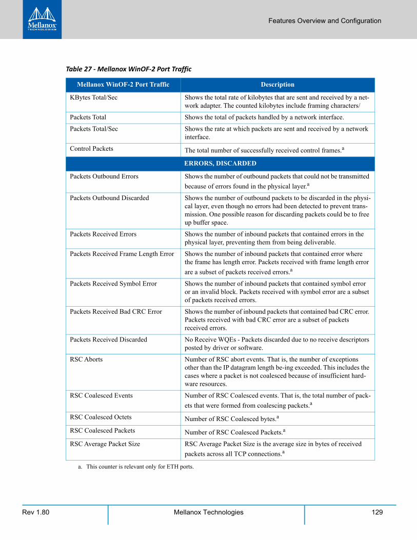
Features Overview and Configuration
Rev 1.80 129Mellanox Technologies
KBytes Total/Sec Shows the total rate of kilobytes that are sent and received by a net-work adapter. The counted kilobytes include framing characters/
Packets Total Shows the total of packets handled by a network interface.
Packets Total/Sec Shows the rate at which packets are sent and received by a network interface.
Control Packets The total number of successfully received control frames.a
ERRORS, DISCARDED
Packets Outbound Errors Shows the number of outbound packets that could not be transmitted
because of errors found in the physical layer.a
Packets Outbound Discarded Shows the number of outbound packets to be discarded in the physi-cal layer, even though no errors had been detected to prevent trans-mission. One possible reason for discarding packets could be to free up buffer space.
Packets Received Errors Shows the number of inbound packets that contained errors in the physical layer, preventing them from being deliverable.
Packets Received Frame Length Error Shows the number of inbound packets that contained error where the frame has length error. Packets received with frame length error
are a subset of packets received errors.a
Packets Received Symbol Error Shows the number of inbound packets that contained symbol error or an invalid block. Packets received with symbol error are a subset of packets received errors.
Packets Received Bad CRC Error Shows the number of inbound packets that contained bad CRC error. Packets received with bad CRC error are a subset of packets received errors.
Packets Received Discarded No Receive WQEs - Packets discarded due to no receive descriptors posted by driver or software.
RSC Aborts Number of RSC abort events. That is, the number of exceptions other than the IP datagram length be-ing exceeded. This includes the cases where a packet is not coalesced because of insufficient hard-ware resources.
RSC Coalesced Events Number of RSC Coalesced events. That is, the total number of pack-
ets that were formed from coalescing packets.a
RSC Coalesced Octets Number of RSC Coalesced bytes.a
RSC Coalesced Packets Number of RSC Coalesced Packets.a
RSC Average Packet Size RSC Average Packet Size is the average size in bytes of received
packets across all TCP connections.a
a. This counter is relevant only for ETH ports.
Table 27 - Mellanox WinOF-2 Port Traffic
Mellanox WinOF-2 Port Traffic Description
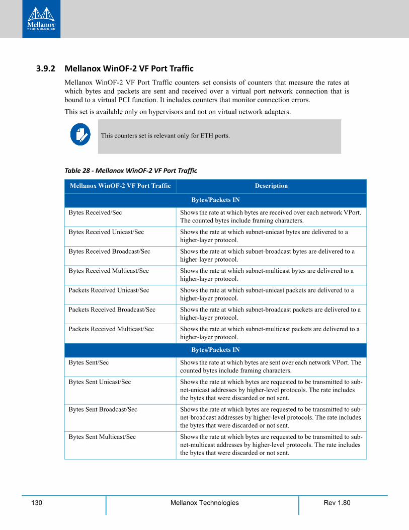
Rev 1.80130 Mellanox Technologies
3.9.2 Mellanox WinOF-2 VF Port TrafficMellanox WinOF-2 VF Port Traffic counters set consists of counters that measure the rates at which bytes and packets are sent and received over a virtual port network connection that is bound to a virtual PCI function. It includes counters that monitor connection errors.
This set is available only on hypervisors and not on virtual network adapters.
This counters set is relevant only for ETH ports.
Table 28 - Mellanox WinOF-2 VF Port Traffic
Mellanox WinOF-2 VF Port Traffic Description
Bytes/Packets IN
Bytes Received/Sec Shows the rate at which bytes are received over each network VPort. The counted bytes include framing characters.
Bytes Received Unicast/Sec Shows the rate at which subnet-unicast bytes are delivered to a higher-layer protocol.
Bytes Received Broadcast/Sec Shows the rate at which subnet-broadcast bytes are delivered to a higher-layer protocol.
Bytes Received Multicast/Sec Shows the rate at which subnet-multicast bytes are delivered to a higher-layer protocol.
Packets Received Unicast/Sec Shows the rate at which subnet-unicast packets are delivered to a higher-layer protocol.
Packets Received Broadcast/Sec Shows the rate at which subnet-broadcast packets are delivered to a higher-layer protocol.
Packets Received Multicast/Sec Shows the rate at which subnet-multicast packets are delivered to a higher-layer protocol.
Bytes/Packets IN
Bytes Sent/Sec Shows the rate at which bytes are sent over each network VPort. The counted bytes include framing characters.
Bytes Sent Unicast/Sec Shows the rate at which bytes are requested to be transmitted to sub-net-unicast addresses by higher-level protocols. The rate includes the bytes that were discarded or not sent.
Bytes Sent Broadcast/Sec Shows the rate at which bytes are requested to be transmitted to sub-net-broadcast addresses by higher-level protocols. The rate includes the bytes that were discarded or not sent.
Bytes Sent Multicast/Sec Shows the rate at which bytes are requested to be transmitted to sub-net-multicast addresses by higher-level protocols. The rate includes the bytes that were discarded or not sent.
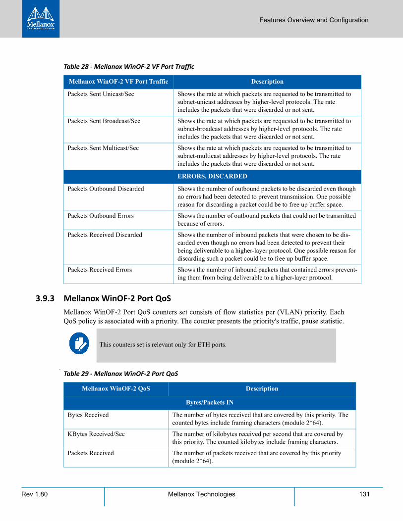
Features Overview and Configuration
Rev 1.80 131Mellanox Technologies
3.9.3 Mellanox WinOF-2 Port QoSMellanox WinOF-2 Port QoS counters set consists of flow statistics per (VLAN) priority. Each QoS policy is associated with a priority. The counter presents the priority's traffic, pause statistic.
.
Packets Sent Unicast/Sec Shows the rate at which packets are requested to be transmitted to subnet-unicast addresses by higher-level protocols. The rate includes the packets that were discarded or not sent.
Packets Sent Broadcast/Sec Shows the rate at which packets are requested to be transmitted to subnet-broadcast addresses by higher-level protocols. The rate includes the packets that were discarded or not sent.
Packets Sent Multicast/Sec Shows the rate at which packets are requested to be transmitted to subnet-multicast addresses by higher-level protocols. The rate includes the packets that were discarded or not sent.
ERRORS, DISCARDED
Packets Outbound Discarded Shows the number of outbound packets to be discarded even though no errors had been detected to prevent transmission. One possible reason for discarding a packet could be to free up buffer space.
Packets Outbound Errors Shows the number of outbound packets that could not be transmitted because of errors.
Packets Received Discarded Shows the number of inbound packets that were chosen to be dis-carded even though no errors had been detected to prevent their being deliverable to a higher-layer protocol. One possible reason for discarding such a packet could be to free up buffer space.
Packets Received Errors Shows the number of inbound packets that contained errors prevent-ing them from being deliverable to a higher-layer protocol.
This counters set is relevant only for ETH ports.
Table 29 - Mellanox WinOF-2 Port QoS
Mellanox WinOF-2 QoS Description
Bytes/Packets IN
Bytes Received The number of bytes received that are covered by this priority. The counted bytes include framing characters (modulo 2^64).
KBytes Received/Sec The number of kilobytes received per second that are covered by this priority. The counted kilobytes include framing characters.
Packets Received The number of packets received that are covered by this priority (modulo 2^64).
Table 28 - Mellanox WinOF-2 VF Port Traffic
Mellanox WinOF-2 VF Port Traffic Description
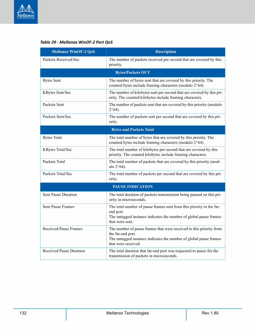
Rev 1.80132 Mellanox Technologies
Packets Received/Sec The number of packets received per second that are covered by this priority.
Bytes/Packets OUT
Bytes Sent The number of bytes sent that are covered by this priority. The counted bytes include framing characters (modulo 2^64).
KBytes Sent/Sec The number of kilobytes sent per second that are covered by this pri-ority. The counted kilobytes include framing characters.
Packets Sent The number of packets sent that are covered by this priority (modulo 2^64).
Packets Sent/Sec The number of packets sent per second that are covered by this pri-ority.
Bytes and Packets Total
Bytes Total The total number of bytes that are covered by this priority. The counted bytes include framing characters (modulo 2^64).
KBytes Total/Sec The total number of kilobytes per second that are covered by this priority. The counted kilobytes include framing characters.
Packets Total The total number of packets that are covered by this priority (mod-ulo 2^64).
Packets Total/Sec The total number of packets per second that are covered by this pri-ority.
PAUSE INDICATION
Sent Pause Duration The total duration of packets transmission being paused on this pri-ority in microseconds.
Sent Pause Frames The total number of pause frames sent from this priority to the far-end port. The untagged instance indicates the number of global pause frames that were sent.
Received Pause Frames The number of pause frames that were received to this priority from the far-end port. The untagged instance indicates the number of global pause frames that were received.
Received Pause Duration The total duration that far-end port was requested to pause for the transmission of packets in microseconds.
Table 29 - Mellanox WinOF-2 Port QoS
Mellanox WinOF-2 QoS Description
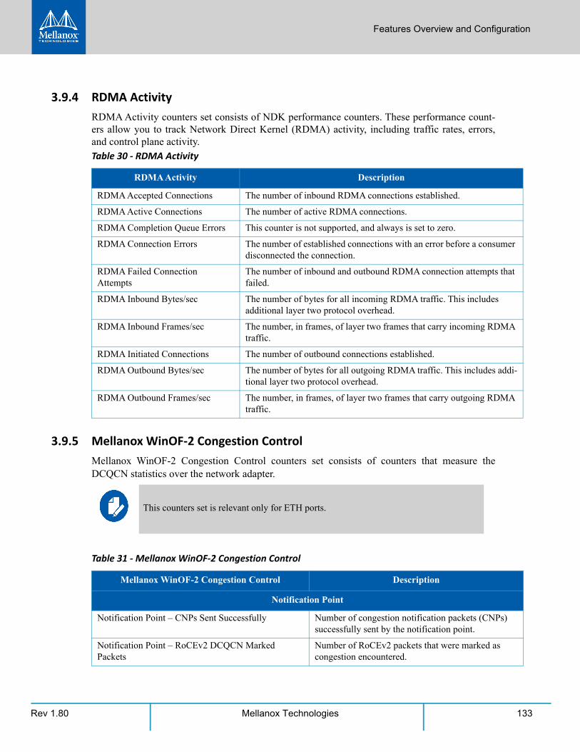
Features Overview and Configuration
Rev 1.80 133Mellanox Technologies
3.9.4 RDMA ActivityRDMA Activity counters set consists of NDK performance counters. These performance count-ers allow you to track Network Direct Kernel (RDMA) activity, including traffic rates, errors, and control plane activity.
3.9.5 Mellanox WinOF-2 Congestion ControlMellanox WinOF-2 Congestion Control counters set consists of counters that measure the DCQCN statistics over the network adapter.
Table 30 - RDMA Activity
RDMA Activity Description
RDMA Accepted Connections The number of inbound RDMA connections established.
RDMA Active Connections The number of active RDMA connections.
RDMA Completion Queue Errors This counter is not supported, and always is set to zero.
RDMA Connection Errors The number of established connections with an error before a consumer disconnected the connection.
RDMA Failed Connection Attempts
The number of inbound and outbound RDMA connection attempts that failed.
RDMA Inbound Bytes/sec The number of bytes for all incoming RDMA traffic. This includes additional layer two protocol overhead.
RDMA Inbound Frames/sec The number, in frames, of layer two frames that carry incoming RDMA traffic.
RDMA Initiated Connections The number of outbound connections established.
RDMA Outbound Bytes/sec The number of bytes for all outgoing RDMA traffic. This includes addi-tional layer two protocol overhead.
RDMA Outbound Frames/sec The number, in frames, of layer two frames that carry outgoing RDMA traffic.
This counters set is relevant only for ETH ports.
Table 31 - Mellanox WinOF-2 Congestion Control
Mellanox WinOF-2 Congestion Control Description
Notification Point
Notification Point – CNPs Sent Successfully Number of congestion notification packets (CNPs) successfully sent by the notification point.
Notification Point – RoCEv2 DCQCN Marked Packets
Number of RoCEv2 packets that were marked as congestion encountered.
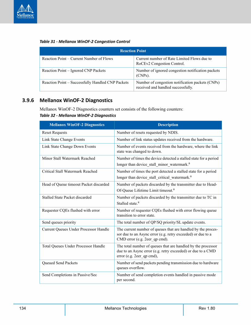
Rev 1.80134 Mellanox Technologies
3.9.6 Mellanox WinOF-2 DiagnosticsMellanox WinOF-2 Diagnostics counters set consists of the following counters:
Reaction Point
Reaction Point – Current Number of Flows Current number of Rate Limited Flows due to RoCEv2 Congestion Control.
Reaction Point – Ignored CNP Packets Number of ignored congestion notification packets (CNPs).
Reaction Point – Successfully Handled CNP Packets Number of congestion notification packets (CNPs) received and handled successfully.
Table 32 - Mellanox WinOF-2 Diagnostics
Mellanox WinOF-2 Diagnostics Description
Reset Requests Number of resets requested by NDIS.
Link State Change Events Number of link status updates received from the hardware.
Link State Change Down Events Number of events received from the hardware, where the link state was changed to down.
Minor Stall Watermark Reached Number of times the device detected a stalled state for a period
longer than device_stall_minor_watermark.a
Critical Stall Watermark Reached Number of times the port detected a stalled state for a period
longer than device_stall_critical_watermark.a
Head of Queue timeout Packet discarded Number of packets discarded by the transmitter due to Head-
Of-Queue Lifetime Limit timeout.a
Stalled State Packet discarded Number of packets discarded by the transmitter due to TC in
Stalled state.a
Requester CQEs flushed with error Number of requester CQEs flushed with error flowing queue transition to error state.
Send queues priority The total number of QP/SQ priority/SL update events.
Current Queues Under Processor Handle The current number of queues that are handled by the proces-sor due to an Async error (e.g. retry exceeded) or due to a CMD error (e.g. 2eer_qp cmd).
Total Queues Under Processor Handle The total number of queues that are handled by the processor due to an Async error (e.g. retry exceeded) or due to a CMD error (e.g. 2eer_qp cmd),
Queued Send Packets Number of send packets pending transmission due to hardware queues overflow.
Send Completions in Passive/Sec Number of send completion events handled in passive mode per second.
Table 31 - Mellanox WinOF-2 Congestion Control
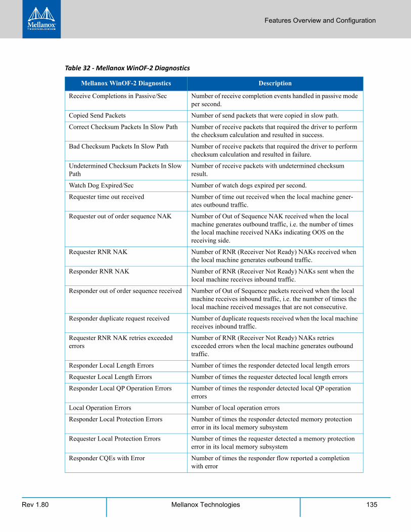
Features Overview and Configuration
Rev 1.80 135Mellanox Technologies
Receive Completions in Passive/Sec Number of receive completion events handled in passive mode per second.
Copied Send Packets Number of send packets that were copied in slow path.
Correct Checksum Packets In Slow Path Number of receive packets that required the driver to perform the checksum calculation and resulted in success.
Bad Checksum Packets In Slow Path Number of receive packets that required the driver to perform checksum calculation and resulted in failure.
Undetermined Checksum Packets In Slow Path
Number of receive packets with undetermined checksum result.
Watch Dog Expired/Sec Number of watch dogs expired per second.
Requester time out received Number of time out received when the local machine gener-ates outbound traffic.
Requester out of order sequence NAK Number of Out of Sequence NAK received when the local machine generates outbound traffic, i.e. the number of times the local machine received NAKs indicating OOS on the receiving side.
Requester RNR NAK Number of RNR (Receiver Not Ready) NAKs received when the local machine generates outbound traffic.
Responder RNR NAK Number of RNR (Receiver Not Ready) NAKs sent when the local machine receives inbound traffic.
Responder out of order sequence received Number of Out of Sequence packets received when the local machine receives inbound traffic, i.e. the number of times the local machine received messages that are not consecutive.
Responder duplicate request received Number of duplicate requests received when the local machine receives inbound traffic.
Requester RNR NAK retries exceeded errors
Number of RNR (Receiver Not Ready) NAKs retries exceeded errors when the local machine generates outbound traffic.
Responder Local Length Errors Number of times the responder detected local length errors
Requester Local Length Errors Number of times the requester detected local length errors
Responder Local QP Operation Errors Number of times the responder detected local QP operation errors
Local Operation Errors Number of local operation errors
Responder Local Protection Errors Number of times the responder detected memory protection error in its local memory subsystem
Requester Local Protection Errors Number of times the requester detected a memory protection error in its local memory subsystem
Responder CQEs with Error Number of times the responder flow reported a completion with error
Table 32 - Mellanox WinOF-2 Diagnostics
Mellanox WinOF-2 Diagnostics Description
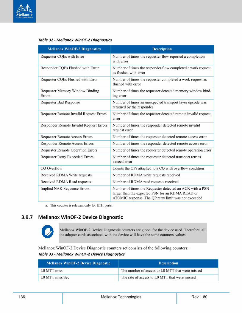
Rev 1.80136 Mellanox Technologies
3.9.7 Mellanox WinOF-2 Device Diagnostic
Mellanox WinOF-2 Device Diagnostic counters set consists of the following counters:.
Requester CQEs with Error Number of times the requester flow reported a completion with error
Responder CQEs Flushed with Error Number of times the responder flow completed a work request as flushed with error
Requester CQEs Flushed with Error Number of times the requester completed a work request as flushed with error
Requester Memory Window Binding Errors
Number of times the requester detected memory window bind-ing error
Requester Bad Response Number of times an unexpected transport layer opcode was returned by the responder
Requester Remote Invalid Request Errors Number of times the requester detected remote invalid request error
Responder Remote Invalid Request Errors Number of times the responder detected remote invalid request error
Requester Remote Access Errors Number of times the requester detected remote access error
Responder Remote Access Errors Number of times the responder detected remote access error
Requester Remote Operation Errors Number of times the requester detected remote operation error
Requester Retry Exceeded Errors Number of times the requester detected transport retries exceed error
CQ Overflow Counts the QPs attached to a CQ with overflow condition
Received RDMA Write requests Number of RDMA write requests received
Received RDMA Read requests Number of RDMA read requests received
Implied NAK Sequence Errors Number of times the Requester detected an ACK with a PSN larger than the expected PSN for an RDMA READ or ATOMIC response. The QP retry limit was not exceeded
a. This counter is relevant only for ETH ports.
Mellanox WinOF-2 Device Diagnostic counters are global for the device used. Therefore, all the adapter cards associated with the device will have the same counters' values.
Table 33 - Mellanox WinOF-2 Device Diagnostics
Mellanox WinOF-2 Device Diagnostic Description
L0 MTT miss The number of access to L0 MTT that were missed
L0 MTT miss/Sec The rate of access to L0 MTT that were missed
Table 32 - Mellanox WinOF-2 Diagnostics
Mellanox WinOF-2 Diagnostics Description
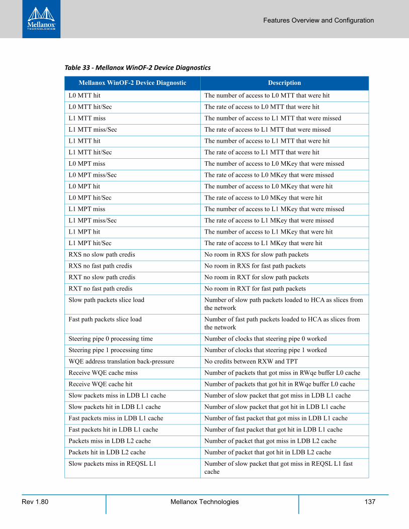
Features Overview and Configuration
Rev 1.80 137Mellanox Technologies
L0 MTT hit The number of access to L0 MTT that were hit
L0 MTT hit/Sec The rate of access to L0 MTT that were hit
L1 MTT miss The number of access to L1 MTT that were missed
L1 MTT miss/Sec The rate of access to L1 MTT that were missed
L1 MTT hit The number of access to L1 MTT that were hit
L1 MTT hit/Sec The rate of access to L1 MTT that were hit
L0 MPT miss The number of access to L0 MKey that were missed
L0 MPT miss/Sec The rate of access to L0 MKey that were missed
L0 MPT hit The number of access to L0 MKey that were hit
L0 MPT hit/Sec The rate of access to L0 MKey that were hit
L1 MPT miss The number of access to L1 MKey that were missed
L1 MPT miss/Sec The rate of access to L1 MKey that were missed
L1 MPT hit The number of access to L1 MKey that were hit
L1 MPT hit/Sec The rate of access to L1 MKey that were hit
RXS no slow path credis No room in RXS for slow path packets
RXS no fast path credis No room in RXS for fast path packets
RXT no slow path credis No room in RXT for slow path packets
RXT no fast path credis No room in RXT for fast path packets
Slow path packets slice load Number of slow path packets loaded to HCA as slices from the network
Fast path packets slice load Number of fast path packets loaded to HCA as slices from the network
Steering pipe 0 processing time Number of clocks that steering pipe 0 worked
Steering pipe 1 processing time Number of clocks that steering pipe 1 worked
WQE address translation back-pressure No credits between RXW and TPT
Receive WQE cache miss Number of packets that got miss in RWqe buffer L0 cache
Receive WQE cache hit Number of packets that got hit in RWqe buffer L0 cache
Slow packets miss in LDB L1 cache Number of slow packet that got miss in LDB L1 cache
Slow packets hit in LDB L1 cache Number of slow packet that got hit in LDB L1 cache
Fast packets miss in LDB L1 cache Number of fast packet that got miss in LDB L1 cache
Fast packets hit in LDB L1 cache Number of fast packet that got hit in LDB L1 cache
Packets miss in LDB L2 cache Number of packet that got miss in LDB L2 cache
Packets hit in LDB L2 cache Number of packet that got hit in LDB L2 cache
Slow packets miss in REQSL L1 Number of slow packet that got miss in REQSL L1 fast cache
Table 33 - Mellanox WinOF-2 Device Diagnostics
Mellanox WinOF-2 Device Diagnostic Description
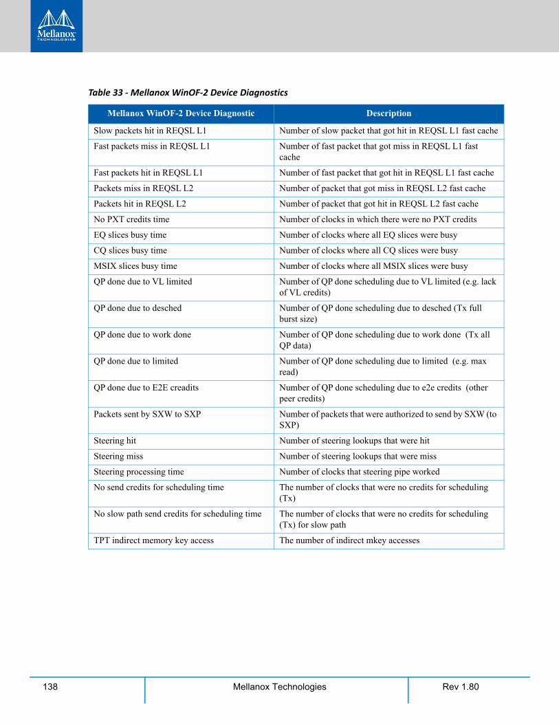
Rev 1.80138 Mellanox Technologies
Slow packets hit in REQSL L1 Number of slow packet that got hit in REQSL L1 fast cache
Fast packets miss in REQSL L1 Number of fast packet that got miss in REQSL L1 fast cache
Fast packets hit in REQSL L1 Number of fast packet that got hit in REQSL L1 fast cache
Packets miss in REQSL L2 Number of packet that got miss in REQSL L2 fast cache
Packets hit in REQSL L2 Number of packet that got hit in REQSL L2 fast cache
No PXT credits time Number of clocks in which there were no PXT credits
EQ slices busy time Number of clocks where all EQ slices were busy
CQ slices busy time Number of clocks where all CQ slices were busy
MSIX slices busy time Number of clocks where all MSIX slices were busy
QP done due to VL limited Number of QP done scheduling due to VL limited (e.g. lack of VL credits)
QP done due to desched Number of QP done scheduling due to desched (Tx full burst size)
QP done due to work done Number of QP done scheduling due to work done (Tx all QP data)
QP done due to limited Number of QP done scheduling due to limited (e.g. max read)
QP done due to E2E creadits Number of QP done scheduling due to e2e credits (other peer credits)
Packets sent by SXW to SXP Number of packets that were authorized to send by SXW (to SXP)
Steering hit Number of steering lookups that were hit
Steering miss Number of steering lookups that were miss
Steering processing time Number of clocks that steering pipe worked
No send credits for scheduling time The number of clocks that were no credits for scheduling (Tx)
No slow path send credits for scheduling time The number of clocks that were no credits for scheduling (Tx) for slow path
TPT indirect memory key access The number of indirect mkey accesses
Table 33 - Mellanox WinOF-2 Device Diagnostics
Mellanox WinOF-2 Device Diagnostic Description
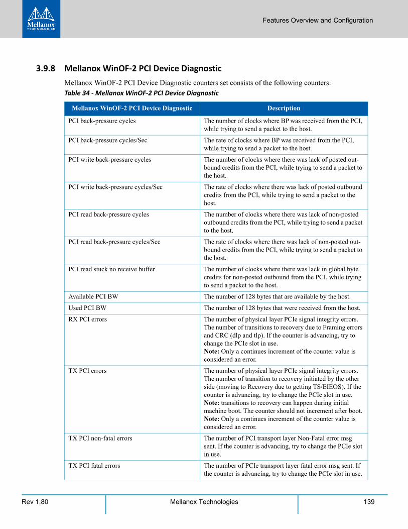
Features Overview and Configuration
Rev 1.80 139Mellanox Technologies
3.9.8 Mellanox WinOF-2 PCI Device DiagnosticMellanox WinOF-2 PCI Device Diagnostic counters set consists of the following counters:
Table 34 - Mellanox WinOF-2 PCI Device Diagnostic
Mellanox WinOF-2 PCI Device Diagnostic Description
PCI back-pressure cycles The number of clocks where BP was received from the PCI, while trying to send a packet to the host.
PCI back-pressure cycles/Sec The rate of clocks where BP was received from the PCI, while trying to send a packet to the host.
PCI write back-pressure cycles The number of clocks where there was lack of posted out-bound credits from the PCI, while trying to send a packet to the host.
PCI write back-pressure cycles/Sec The rate of clocks where there was lack of posted outbound credits from the PCI, while trying to send a packet to the host.
PCI read back-pressure cycles The number of clocks where there was lack of non-posted outbound credits from the PCI, while trying to send a packet to the host.
PCI read back-pressure cycles/Sec The rate of clocks where there was lack of non-posted out-bound credits from the PCI, while trying to send a packet to the host.
PCI read stuck no receive buffer The number of clocks where there was lack in global byte credits for non-posted outbound from the PCI, while trying to send a packet to the host.
Available PCI BW The number of 128 bytes that are available by the host.
Used PCI BW The number of 128 bytes that were received from the host.
RX PCI errors The number of physical layer PCIe signal integrity errors. The number of transitions to recovery due to Framing errors and CRC (dlp and tlp). If the counter is advancing, try to change the PCIe slot in use.Note: Only a continues increment of the counter value is considered an error.
TX PCI errors The number of physical layer PCIe signal integrity errors. The number of transition to recovery initiated by the other side (moving to Recovery due to getting TS/EIEOS). If the counter is advancing, try to change the PCIe slot in use.Note: transitions to recovery can happen during initial machine boot. The counter should not increment after boot.Note: Only a continues increment of the counter value is considered an error.
TX PCI non-fatal errors The number of PCI transport layer Non-Fatal error msg sent. If the counter is advancing, try to change the PCIe slot in use.
TX PCI fatal errors The number of PCIe transport layer fatal error msg sent. If the counter is advancing, try to change the PCIe slot in use.
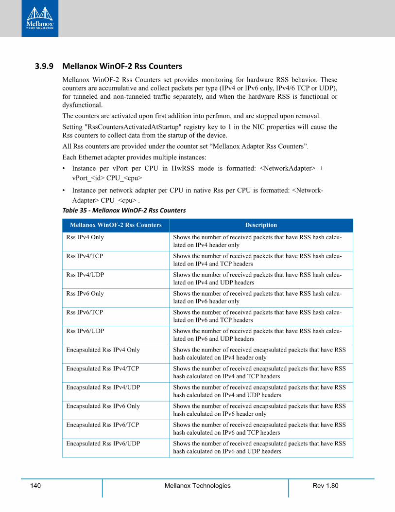
Rev 1.80140 Mellanox Technologies
3.9.9 Mellanox WinOF-2 Rss Counters Mellanox WinOF-2 Rss Counters set provides monitoring for hardware RSS behavior. These counters are accumulative and collect packets per type (IPv4 or IPv6 only, IPv4/6 TCP or UDP), for tunneled and non-tunneled traffic separately, and when the hardware RSS is functional or dysfunctional.
The counters are activated upon first addition into perfmon, and are stopped upon removal.
Setting "RssCountersActivatedAtStartup" registry key to 1 in the NIC properties will cause the Rss counters to collect data from the startup of the device.
All Rss counters are provided under the counter set “Mellanox Adapter Rss Counters”.
Each Ethernet adapter provides multiple instances:
• Instance per vPort per CPU in HwRSS mode is formatted: <NetworkAdapter> + vPort_<id> CPU_<cpu>
• Instance per network adapter per CPU in native Rss per CPU is formatted: <Network-
Adapter> CPU_<cpu> .
Table 35 - Mellanox WinOF-2 Rss Counters
Mellanox WinOF-2 Rss Counters Description
Rss IPv4 Only Shows the number of received packets that have RSS hash calcu-lated on IPv4 header only
Rss IPv4/TCP Shows the number of received packets that have RSS hash calcu-lated on IPv4 and TCP headers
Rss IPv4/UDP Shows the number of received packets that have RSS hash calcu-lated on IPv4 and UDP headers
Rss IPv6 Only Shows the number of received packets that have RSS hash calcu-lated on IPv6 header only
Rss IPv6/TCP Shows the number of received packets that have RSS hash calcu-lated on IPv6 and TCP headers
Rss IPv6/UDP Shows the number of received packets that have RSS hash calcu-lated on IPv6 and UDP headers
Encapsulated Rss IPv4 Only Shows the number of received encapsulated packets that have RSS hash calculated on IPv4 header only
Encapsulated Rss IPv4/TCP Shows the number of received encapsulated packets that have RSS hash calculated on IPv4 and TCP headers
Encapsulated Rss IPv4/UDP Shows the number of received encapsulated packets that have RSS hash calculated on IPv4 and UDP headers
Encapsulated Rss IPv6 Only Shows the number of received encapsulated packets that have RSS hash calculated on IPv6 header only
Encapsulated Rss IPv6/TCP Shows the number of received encapsulated packets that have RSS hash calculated on IPv6 and TCP headers
Encapsulated Rss IPv6/UDP Shows the number of received encapsulated packets that have RSS hash calculated on IPv6 and UDP headers
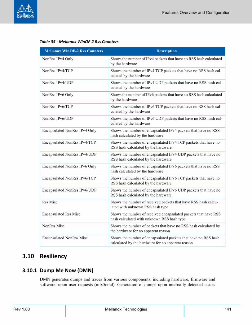
Features Overview and Configuration
Rev 1.80 141Mellanox Technologies
3.10 Resiliency
3.10.1 Dump Me Now (DMN)DMN generates dumps and traces from various components, including hardware, firmware and software, upon user requests (mlx5cmd). Generation of dumps upon internally detected issues
NonRss IPv4 Only Shows the number of IPv4 packets that have no RSS hash calculated by the hardware
NonRss IPv4/TCP Shows the number of IPv4 TCP packets that have no RSS hash cal-culated by the hardware
NonRss IPv4/UDP Shows the number of IPv4 UDP packets that have no RSS hash cal-culated by the hardware
NonRss IPv6 Only Shows the number of IPv6 packets that have no RSS hash calculated by the hardware
NonRss IPv6/TCP Shows the number of IPv6 TCP packets that have no RSS hash cal-culated by the hardware
NonRss IPv6/UDP Shows the number of IPv6 UDP packets that have no RSS hash cal-culated by the hardware
Encapsulated NonRss IPv4 Only Shows the number of encapsulated IPv4 packets that have no RSS hash calculated by the hardware
Encapsulated NonRss IPv4/TCP Shows the number of encapsulated IPv4 TCP packets that have no RSS hash calculated by the hardware
Encapsulated NonRss IPv4/UDP Shows the number of encapsulated IPv4 UDP packets that have no RSS hash calculated by the hardware
Encapsulated NonRss IPv6 Only Shows the number of encapsulated IPv6 packets that have no RSS hash calculated by the hardware
Encapsulated NonRss IPv6/TCP Shows the number of encapsulated IPv6 TCP packets that have no RSS hash calculated by the hardware
Encapsulated NonRss IPv6/UDP Shows the number of encapsulated IPv6 UDP packets that have no RSS hash calculated by the hardware
Rss Misc Shows the number of received packets that have RSS hash calcu-lated with unknown RSS hash type
Encapsulated Rss Misc Shows the number of received encapsulated packets that have RSS hash calculated with unknown RSS hash type
NonRss Misc Shows the number of packets that have no RSS hash calculated by the hardware for no apparent reason
Encapsulated NonRss Misc Shows the number of encapsulated packets that have no RSS hash calculated by the hardware for no apparent reason
Table 35 - Mellanox WinOF-2 Rss Counters
Mellanox WinOF-2 Rss Counters Description
Rev 1.80142 Mellanox Technologies
(by the resiliency sensors) and ND application requests via the extended Mellanox ND API will be added in the future.
DMN dumps are crucial for offline debugging. Once an issue is hit, the dumps can provide useful information about the NIC's state at the time of the failure. This includes hardware state dumps, firmware traces and various driver component state and resource dumps.
For information on the relevant registry keys for this feature, please refer to Section 3.6.8.1, “Dump Me Now (DMN) Registry Keys”, on page 121.
3.10.1.1 DMN Triggers and APIs
DMN currently supports one triggering API (additional APIs will be added in the future):
mlx5cmd.exe can be used to trigger DMN by running the -Dmn subcommand:
Options:
3.10.1.2 Dumps and Incident Folders
DMN generates a directory per incident, where it places all of the needed NIC dump files. There is a mechanism to limit the number of created Incident Directories. See Section 3.10.1.3, “Cyclic DMN Mechanism”, on page 143.
The DMN incident directory name includes a timestamp, dump type, DMN event source and rea-son. It uses the following directory naming scheme:
dmn-<type of DMN>-<source of DMN trigger>-<reason>-<timestamp> Example:
dmn-GENERAL-USER-NA-4.13.2017-07.49.02.747
In this example:
1. The dump type is "general”.
2. The DMN was triggered by mlx5cmd.
3. In this version of the driver, the cause for the dump is not available in case of mlx5cmd trig-gering.
4. The dump was created on April 13th, 2017 at 747 milliseconds after 7:49:02 AM.
In this version of the driver, the DMN generates the following dump files upon a DMN event. Additional files will be added in the future:
1. VmQoS - The adapter's VmQoS configuration and state.
2. IPoIB - The adapter’s IPoIB state.
DMN incident dumps are created under the DMN root directory, which can be controlled via the registry. The default is \Systemroot\temp\Mlx5_Dump_Me_Now. See Section 3.6.8.1, “Dump Me Now (DMN) Registry Keys”, on page 121.
Mlx5cmd -Dmn -hh | -Name <adapter name> Submit dump-me-now request
-hh Show this help screen-Name <adapter name> - Network adapter name
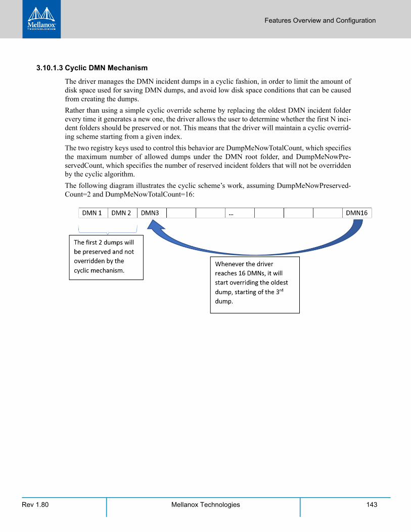
Features Overview and Configuration
Rev 1.80 143Mellanox Technologies
3.10.1.3 Cyclic DMN Mechanism
The driver manages the DMN incident dumps in a cyclic fashion, in order to limit the amount of disk space used for saving DMN dumps, and avoid low disk space conditions that can be caused from creating the dumps.
Rather than using a simple cyclic override scheme by replacing the oldest DMN incident folder every time it generates a new one, the driver allows the user to determine whether the first N inci-dent folders should be preserved or not. This means that the driver will maintain a cyclic overrid-ing scheme starting from a given index.
The two registry keys used to control this behavior are DumpMeNowTotalCount, which specifies the maximum number of allowed dumps under the DMN root folder, and DumpMeNowPre-servedCount, which specifies the number of reserved incident folders that will not be overridden by the cyclic algorithm.
The following diagram illustrates the cyclic scheme’s work, assuming DumpMeNowPreserved-Count=2 and DumpMeNowTotalCount=16:
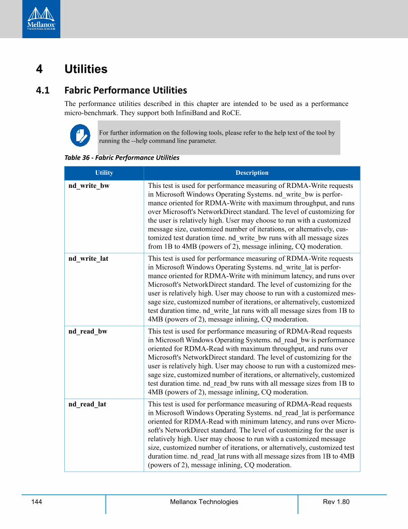
Rev 1.80144 Mellanox Technologies
4 Utilities
4.1 Fabric Performance UtilitiesThe performance utilities described in this chapter are intended to be used as a performance micro-benchmark. They support both InfiniBand and RoCE.
For further information on the following tools, please refer to the help text of the tool by running the --help command line parameter.
Table 36 - Fabric Performance Utilities
Utility Description
nd_write_bw This test is used for performance measuring of RDMA-Write requests in Microsoft Windows Operating Systems. nd_write_bw is perfor-mance oriented for RDMA-Write with maximum throughput, and runs over Microsoft's NetworkDirect standard. The level of customizing for the user is relatively high. User may choose to run with a customized message size, customized number of iterations, or alternatively, cus-tomized test duration time. nd_write_bw runs with all message sizes from 1B to 4MB (powers of 2), message inlining, CQ moderation.
nd_write_lat This test is used for performance measuring of RDMA-Write requests in Microsoft Windows Operating Systems. nd_write_lat is perfor-mance oriented for RDMA-Write with minimum latency, and runs over Microsoft's NetworkDirect standard. The level of customizing for the user is relatively high. User may choose to run with a customized mes-sage size, customized number of iterations, or alternatively, customized test duration time. nd_write_lat runs with all message sizes from 1B to 4MB (powers of 2), message inlining, CQ moderation.
nd_read_bw This test is used for performance measuring of RDMA-Read requests in Microsoft Windows Operating Systems. nd_read_bw is performance oriented for RDMA-Read with maximum throughput, and runs over Microsoft's NetworkDirect standard. The level of customizing for the user is relatively high. User may choose to run with a customized mes-sage size, customized number of iterations, or alternatively, customized test duration time. nd_read_bw runs with all message sizes from 1B to 4MB (powers of 2), message inlining, CQ moderation.
nd_read_lat This test is used for performance measuring of RDMA-Read requests in Microsoft Windows Operating Systems. nd_read_lat is performance oriented for RDMA-Read with minimum latency, and runs over Micro-soft's NetworkDirect standard. The level of customizing for the user is relatively high. User may choose to run with a customized message size, customized number of iterations, or alternatively, customized test duration time. nd_read_lat runs with all message sizes from 1B to 4MB (powers of 2), message inlining, CQ moderation.
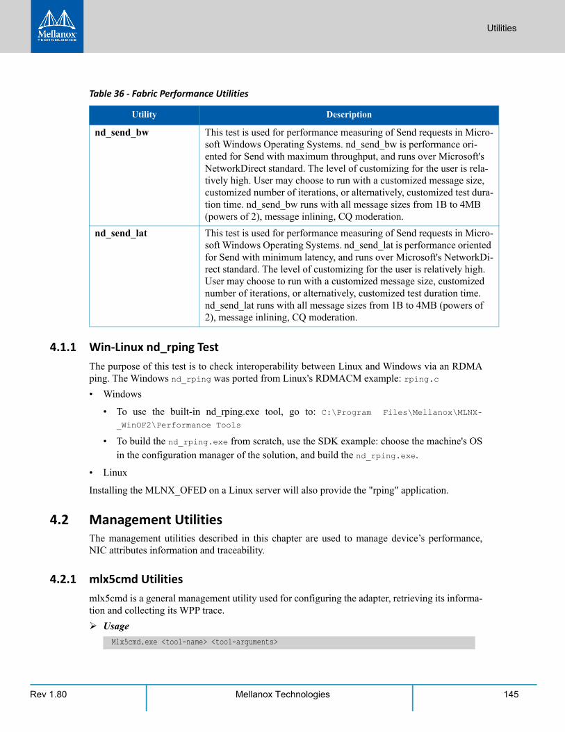
Utilities
Rev 1.80 145Mellanox Technologies
4.1.1 Win-Linux nd_rping TestThe purpose of this test is to check interoperability between Linux and Windows via an RDMA ping. The Windows nd_rping was ported from Linux's RDMACM example: rping.c
• Windows
• To use the built-in nd_rping.exe tool, go to: C:\Program Files\Mellanox\MLNX-
_WinOF2\Performance Tools
• To build the nd_rping.exe from scratch, use the SDK example: choose the machine's OS in the configuration manager of the solution, and build the nd_rping.exe.
• Linux
Installing the MLNX_OFED on a Linux server will also provide the "rping" application.
4.2 Management UtilitiesThe management utilities described in this chapter are used to manage device’s performance, NIC attributes information and traceability.
4.2.1 mlx5cmd Utilitiesmlx5cmd is a general management utility used for configuring the adapter, retrieving its informa-tion and collecting its WPP trace.
Usage
nd_send_bw This test is used for performance measuring of Send requests in Micro-soft Windows Operating Systems. nd_send_bw is performance ori-ented for Send with maximum throughput, and runs over Microsoft's NetworkDirect standard. The level of customizing for the user is rela-tively high. User may choose to run with a customized message size, customized number of iterations, or alternatively, customized test dura-tion time. nd_send_bw runs with all message sizes from 1B to 4MB (powers of 2), message inlining, CQ moderation.
nd_send_lat This test is used for performance measuring of Send requests in Micro-soft Windows Operating Systems. nd_send_lat is performance oriented for Send with minimum latency, and runs over Microsoft's NetworkDi-rect standard. The level of customizing for the user is relatively high. User may choose to run with a customized message size, customized number of iterations, or alternatively, customized test duration time. nd_send_lat runs with all message sizes from 1B to 4MB (powers of 2), message inlining, CQ moderation.
Mlx5cmd.exe <tool-name> <tool-arguments>
Table 36 - Fabric Performance Utilities
Utility Description
Rev 1.80146 Mellanox Technologies
4.2.1.1 Performance Tuning Utility
This utility is used mostly for IP forwarding tests to optimize the driver’s configuration to achieve maximum performance when running in IP router mode.
Usage
4.2.1.2 Information Utility
This utility displays information of Mellanox NIC attributes. It is the equivalent utility to ibstat and vstat utilities in WinOF.
Usage
4.2.1.3 Trace Utility
The utility saves the ETW WPP tracing of the driver.
Usage
4.2.1.4 QoS Configuration Utility
The utility configures Quality of Service (QoS) settings.
Usage
For further information about the parameters, you may refer to Section 3.2.3.2, “RCM Configura-tion”, on page 54.
4.2.1.5 mstdump Utility
This utility creates 3 mstdump file upon user request. For further information on the files created, you may refer to Table 47, “Events Causing Automatic State Dumps,” on page 198.
Usage
• The PCI information can be queried from the “General” properties tab under “Location”.
Example:
If the “Location” is “PCI Slot 3 (PCI bus 8, device 0, function 0)”, run the following command:
• The output will indicate the files location.
Example:
“Mstdump succeeded. Dump files for device at location 8.0.0 were created in c:\windows\temp directory.”
Mlx5cmd.exe -PerfTuning <tool-arguments>
Mlx5cmd.exe -Stat <tool-arguments>
Mlx5cmd.exe -Trace <tool-arguments>
Mlx5cmd.exe -QoSConfig -Name <Network Adapter Name> <-DefaultUntaggedPriority | -Dcqcn>
Mlx5cmd.exe -Mstdump [-bdf <pci-bus#> <pci-device#> <pci-function#>]
Mlx5cmd.exe -Mstdump -bdf 8.0.0
Utilities
Rev 1.80 147Mellanox Technologies
4.2.1.6 Registry Keys Utility
This utility shows the registry keys that were set in the registry and are read by the driver.
Usage
The PCI information can be queried from the "General" properties tab under "Location".
Example:
If the "Location" is "PCI Slot 3 (PCI bus 8, device 0, function 0)", run the following command:
4.2.1.7 Non-RSS Traffic Capture Utility
The RssSniffer utility provides sampling of packets that did not pass through the RSS engine, whether it is non-RSS traffic, or in any other case that the hardware determines to avoid RSS hashing.
The tool generates a packet dump file in a .pcap format. The RSS sampling is performed globally in native RSS mode, or per vPort in virtualization mode, when the hardware vRSS mode is active.
For detailed usage, run mlx5cmd.exe -RssSniffer -hh
4.2.1.8 Sniffer Utility
Sniffer utility provides the user with the ability to capture Ethernet and RoCE traffic that flows to and from the Mellanox NIC's ports The tool generates a packet dump file in .pcap format. This file can be read using the Wireshark tool (www.wireshark.org) for graphical traffic analysis.
For detailed usage, run mlx5cmd.exe -sniffer -help
4.2.1.9 Link Speed Utility
This utility provides the ability to query supported link speeds by the adapter. Additionally, it enables the user to force set a particular link speed that the adapter can support.
Usage
Example:
For detailed usage, run mlx5cmd.exe -LinkSpeed -hh
Mlx5Cmd.exe -RegKeys [-bdf <pci-bus#> <pci-device#> <pci-function#>]
Mlx5Cmd.exe -RegKeys -bdf 8.0.0
Note that the tool can be configured to capture only a part of the packet, as well as specific packets in a sequence (N-th).
Mlx5Cmd -LinkSpeed -Name <Network Adapter Name> -Query
Mlx5Cmd -LinkSpeed -Name <Network Adapter Name> -Set 1
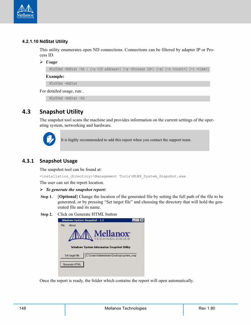
Rev 1.80148 Mellanox Technologies
4.2.1.10 NdStat Utility
This utility enumerates open ND connections. Connections can be filtered by adapter IP or Pro-cess ID.
Usage
Example:
For detailed usage, run:.
4.3 Snapshot UtilityThe snapshot tool scans the machine and provides information on the current settings of the oper-ating system, networking and hardware.
4.3.1 Snapshot UsageThe snapshot tool can be found at:
<installation_directory>\Management Tools\MLNX_System_Snapshot.exe
The user can set the report location.
To generate the snapshot report:
Step 1. [Optional] Change the location of the generated file by setting the full path of the file to be generated, or by pressing “Set target file” and choosing the directory that will hold the gen-erated file and its name.
Step 2. Click on Generate HTML button
Once the report is ready, the folder which contains the report will open automatically.
Mlx5Cmd -NdStat -hh | [-a <IP address>] [-p <Process Id>] [-e] [-n <count>] [-t <time>]
Mlx5Cmd -NdStat
Mlx5Cmd -NdStat -hh
It is highly recommended to add this report when you contact the support team.

Utilities
Rev 1.80 149Mellanox Technologies

Rev 1.80150 Mellanox Technologies

Utilities
Rev 1.80 151Mellanox Technologies

Rev 1.80152 Mellanox Technologies

Utilities
Rev 1.80 153Mellanox Technologies

Rev 1.80154 Mellanox Technologies

Utilities
Rev 1.80 155Mellanox Technologies

Rev 1.80156 Mellanox Technologies

Utilities
Rev 1.80 157Mellanox Technologies

Rev 1.80158 Mellanox Technologies

Utilities
Rev 1.80 159Mellanox Technologies

Rev 1.80160 Mellanox Technologies

Utilities
Rev 1.80 161Mellanox Technologies

Rev 1.80162 Mellanox Technologies

Utilities
Rev 1.80 163Mellanox Technologies

Rev 1.80164 Mellanox Technologies

Utilities
Rev 1.80 165Mellanox Technologies

Rev 1.80166 Mellanox Technologies

Utilities
Rev 1.80 167Mellanox Technologies

Rev 1.80168 Mellanox Technologies

Utilities
Rev 1.80 169Mellanox Technologies

Rev 1.80170 Mellanox Technologies

Utilities
Rev 1.80 171Mellanox Technologies

Rev 1.80172 Mellanox Technologies

Utilities
Rev 1.80 173Mellanox Technologies

Rev 1.80174 Mellanox Technologies

Utilities
Rev 1.80 175Mellanox Technologies

Rev 1.80176 Mellanox Technologies

Utilities
Rev 1.80 177Mellanox Technologies

Rev 1.80178 Mellanox Technologies

Utilities
Rev 1.80 179Mellanox Technologies

Rev 1.80180 Mellanox Technologies

Utilities
Rev 1.80 181Mellanox Technologies

Rev 1.80182 Mellanox Technologies

Utilities
Rev 1.80 183Mellanox Technologies

Rev 1.80184 Mellanox Technologies

Utilities
Rev 1.80 185Mellanox Technologies
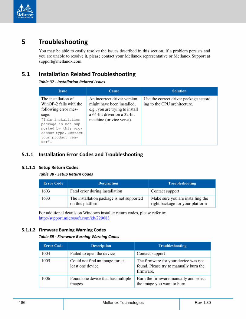
Rev 1.80186 Mellanox Technologies
5 TroubleshootingYou may be able to easily resolve the issues described in this section. If a problem persists and you are unable to resolve it, please contact your Mellanox representative or Mellanox Support at [email protected].
5.1 Installation Related Troubleshooting
5.1.1 Installation Error Codes and Troubleshooting
5.1.1.1 Setup Return Codes
For additional details on Windows installer return codes, please refer to: http://support.microsoft.com/kb/229683
5.1.1.2 Firmware Burning Warning Codes
Table 37 - Installation Related Issues
Issue Cause Solution
The installation of WinOF-2 fails with the following error mes-sage:“This installation package is not sup-ported by this pro-cessor type. Contact your product ven-dor".
An incorrect driver version might have been installed, e.g., you are trying to install a 64-bit driver on a 32-bit machine (or vice versa).
Use the correct driver package accord-ing to the CPU architecture.
Table 38 - Setup Return Codes
Error Code Description Troubleshooting
1603 Fatal error during installation Contact support
1633 The installation package is not supported on this platform.
Make sure you are installing the right package for your platform
Table 39 - Firmware Burning Warning Codes
Error Code Description Troubleshooting
1004 Failed to open the device Contact support
1005 Could not find an image for at least one device
The firmware for your device was not found. Please try to manually burn the firmware.
1006 Found one device that has multiple images
Burn the firmware manually and select the image you want to burn.

Troubleshooting
Rev 1.80 187Mellanox Technologies
For additional details, please refer to the MFT User Manual:
http://www.mellanox.com > Products > Firmware Tools
5.1.1.3 Restore Configuration Warnings
1007 Found one device for which force update is required
Burn the firmware manually with the force flag.
1008 Found one device that has mixed versions
The firmware version or the expansion rom version does not match.
Table 40 - Restore Configuration Warnings
Error Code Description Troubleshooting
3 Failed to restore the configu-ration
Please see log for more details and contact the support team
Table 39 - Firmware Burning Warning Codes
Error Code Description Troubleshooting
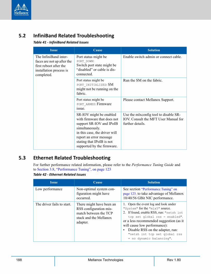
Rev 1.80188 Mellanox Technologies
5.2 InfiniBand Related Troubleshooting
5.3 Ethernet Related TroubleshootingFor further performance related information, please refer to the Performance Tuning Guide and to Section 3.8, “Performance Tuning”, on page 123
Table 41 - InfiniBand Related Issues
Issue Cause Solution
The InfiniBand inter-faces are not up after the first reboot after the installation process is completed.
Port status might be PORT_DOWN: Switch port state might be “disabled” or cable is dis-connected.
Enable switch admin or connect cable.
Port status might be PORT_INITIALIZED: SM might not be running on the fabric.
Run the SM on the fabric.
Port status might be PORT_ARMED: Firmware issue.
Please contact Mellanox Support.
SR-IOV might be enabled with firmware that does not support SR-IOV and IPoIB simultaneously.in this case, the driver will report an error message stating that IPoIB is not supported by the firmware.
Use the mlxconfig tool to disable SR-IOV. Consult the MFT User Manual for further details.
Table 42 - Ethernet Related Issues
Issue Cause Solution
Low performance Non-optimal system con-figuration might have occurred.
See section “Performance Tuning” on page 123. to take advantage of Mellanox 10/40/56 GBit NIC performance.
The driver fails to start. There might have been an RSS configuration mis-match between the TCP stack and the Mellanox adapter.
1. Open the event log and look under "System" for the "mlx5" source. 2. If found, enable RSS, run: "netsh int
tcp set global rss = enabled".or a less recommended suggestion (as it will cause low performance): • Disable RSS on the adapter, run:
"netsh int tcp set global rss = no dynamic balancing".

Troubleshooting
Rev 1.80 189Mellanox Technologies
The driver fails to start and a yellow sign appears near the "Mel-lanox ConnectX-4/ConnectX-5 Adapter <X>" in the Device Manager display. (Code 10)
Look into the Event Viewer to view the error.
• If the failure occurred due to unsup-ported mode type, refer to Section 3.1.1, “Port Management” for the solution.
• If the solution isn't mentioned in event viewer, disable and re-enable "Mellanox ConnectX-4/ConnectX-5 Adapter <X>" from the Device Manager display. If the failure resumes, please refer to Mellanox support at [email protected].
No connectivity to a Fault Tolerance team while using network capture tools (e.g., Wireshark).
The network capture tool might have captured the network traffic of the non-active adapter in the team. This is not allowed since the tool sets the packet filter to "promiscuous", thus causing traffic to be trans-ferred on multiple inter-faces.
Close the network capture tool on the physical adapter card, and set it on the team interface instead.
No Ethernet connectiv-ity on 10Gb adapters after activating Perfor-mance Tuning (part of the installation).
A TcpWindowSize registry value might have been added.
• Remove the value key under HKEY_LOCAL_MACHINE\SYSTEM\Cur-rentControlSet\Ser-vices\Tcpip\Parameters\TcpWindowSize Or
• Set its value to 0xFFFF.
Packets are being lost. The port MTU might have been set to a value higher than the maximum MTU supported by the switch.
Change the MTU according to the maxi-mum MTU supported by the switch.
NVGRE changes done on a running VM, are not propagated to the VM.
The configuration changes might not have taken effect until the OS is restarted.
Stop the VM and afterwards perform any NVGRE configuration changes on the VM connected to the virtual switch.
Table 42 - Ethernet Related Issues
Issue Cause Solution
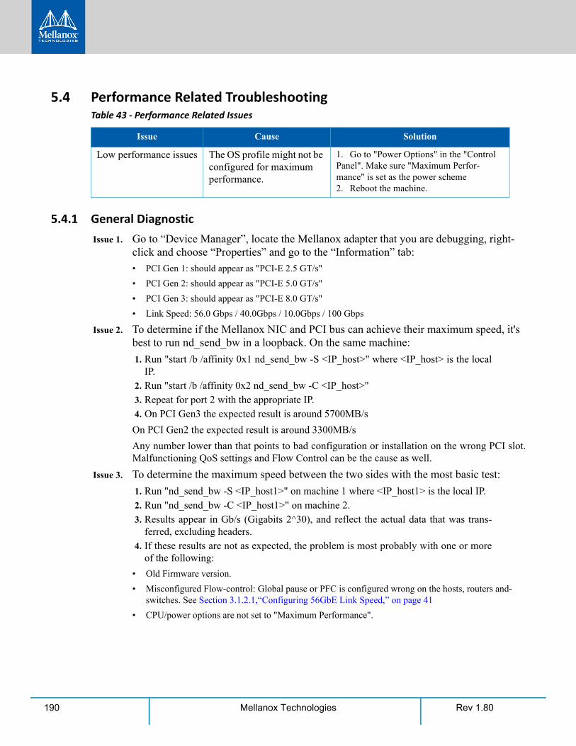
Rev 1.80190 Mellanox Technologies
5.4 Performance Related Troubleshooting
5.4.1 General DiagnosticIssue 1. Go to “Device Manager”, locate the Mellanox adapter that you are debugging, right-
click and choose “Properties” and go to the “Information” tab:
• PCI Gen 1: should appear as "PCI-E 2.5 GT/s"
• PCI Gen 2: should appear as "PCI-E 5.0 GT/s"
• PCI Gen 3: should appear as "PCI-E 8.0 GT/s"
• Link Speed: 56.0 Gbps / 40.0Gbps / 10.0Gbps / 100 Gbps
Issue 2. To determine if the Mellanox NIC and PCI bus can achieve their maximum speed, it's best to run nd_send_bw in a loopback. On the same machine:
1. Run "start /b /affinity 0x1 nd_send_bw -S <IP_host>" where <IP_host> is the local IP.
2. Run "start /b /affinity 0x2 nd_send_bw -C <IP_host>" 3. Repeat for port 2 with the appropriate IP. 4. On PCI Gen3 the expected result is around 5700MB/s
On PCI Gen2 the expected result is around 3300MB/s
Any number lower than that points to bad configuration or installation on the wrong PCI slot. Malfunctioning QoS settings and Flow Control can be the cause as well.
Issue 3. To determine the maximum speed between the two sides with the most basic test:
1. Run "nd_send_bw -S <IP_host1>" on machine 1 where <IP_host1> is the local IP. 2. Run "nd_send_bw -C <IP_host1>" on machine 2. 3. Results appear in Gb/s (Gigabits 2^30), and reflect the actual data that was trans-
ferred, excluding headers. 4. If these results are not as expected, the problem is most probably with one or more
of the following:
• Old Firmware version.
• Misconfigured Flow-control: Global pause or PFC is configured wrong on the hosts, routers and-switches. See Section 3.1.2.1,“Configuring 56GbE Link Speed,” on page 41
• CPU/power options are not set to "Maximum Performance".
Table 43 - Performance Related Issues
Issue Cause Solution
Low performance issues The OS profile might not be configured for maximum performance.
1. Go to "Power Options" in the "Control Panel". Make sure "Maximum Perfor-mance" is set as the power scheme2. Reboot the machine.
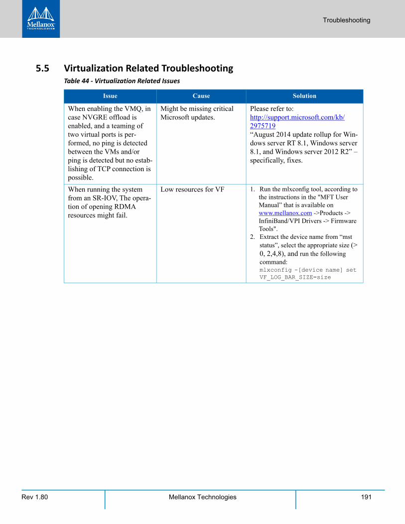
Troubleshooting
Rev 1.80 191Mellanox Technologies
5.5 Virtualization Related TroubleshootingTable 44 - Virtualization Related Issues
Issue Cause Solution
When enabling the VMQ, in case NVGRE offload is enabled, and a teaming of two virtual ports is per-formed, no ping is detected between the VMs and/or ping is detected but no estab-lishing of TCP connection is possible.
Might be missing critical Microsoft updates.
Please refer to:http://support.microsoft.com/kb/2975719 “August 2014 update rollup for Win-dows server RT 8.1, Windows server 8.1, and Windows server 2012 R2” – specifically, fixes.
When running the system from an SR-IOV, The opera-tion of opening RDMA resources might fail.
Low resources for VF 1. Run the mlxconfig tool, according to the instructions in the "MFT User Manual” that is available on www.mellanox.com ->Products -> InfiniBand/VPI Drivers -> Firmware Tools".
2. Extract the device name from “mst status”, select the appropriate size (> 0, 2,4,8), and run the following command: mlxconfig -[device name] set VF_LOG_BAR_SIZE=size
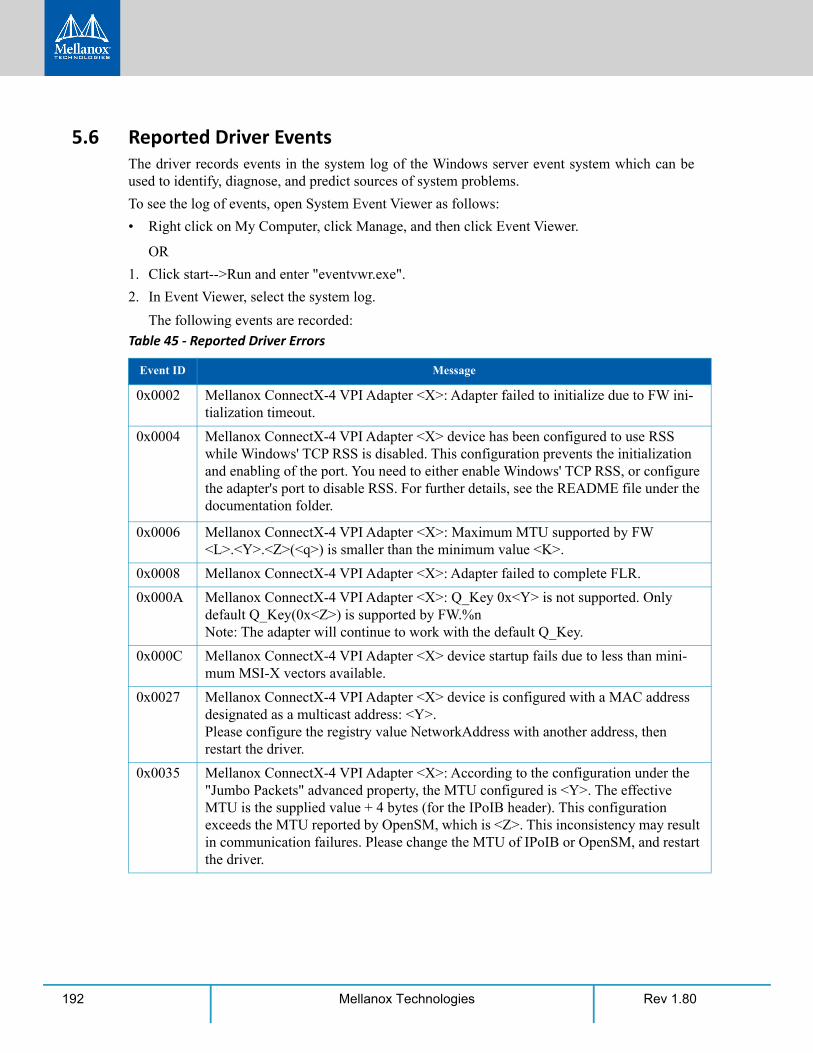
Rev 1.80192 Mellanox Technologies
5.6 Reported Driver EventsThe driver records events in the system log of the Windows server event system which can be used to identify, diagnose, and predict sources of system problems.
To see the log of events, open System Event Viewer as follows:
• Right click on My Computer, click Manage, and then click Event Viewer.
OR
1. Click start-->Run and enter "eventvwr.exe".
2. In Event Viewer, select the system log.
The following events are recorded:
Table 45 - Reported Driver Errors
Event ID Message
0x0002 Mellanox ConnectX-4 VPI Adapter <X>: Adapter failed to initialize due to FW ini-tialization timeout.
0x0004 Mellanox ConnectX-4 VPI Adapter <X> device has been configured to use RSS while Windows' TCP RSS is disabled. This configuration prevents the initialization and enabling of the port. You need to either enable Windows' TCP RSS, or configure the adapter's port to disable RSS. For further details, see the README file under the documentation folder.
0x0006 Mellanox ConnectX-4 VPI Adapter <X>: Maximum MTU supported by FW <L>.<Y>.<Z>(<q>) is smaller than the minimum value <K>.
0x0008 Mellanox ConnectX-4 VPI Adapter <X>: Adapter failed to complete FLR.
0x000A Mellanox ConnectX-4 VPI Adapter <X>: Q_Key 0x<Y> is not supported. Only default Q_Key(0x<Z>) is supported by FW.%nNote: The adapter will continue to work with the default Q_Key.
0x000C Mellanox ConnectX-4 VPI Adapter <X> device startup fails due to less than mini-mum MSI-X vectors available.
0x0027 Mellanox ConnectX-4 VPI Adapter <X> device is configured with a MAC address designated as a multicast address: <Y>.Please configure the registry value NetworkAddress with another address, then restart the driver.
0x0035 Mellanox ConnectX-4 VPI Adapter <X>: According to the configuration under the "Jumbo Packets" advanced property, the MTU configured is <Y>. The effective MTU is the supplied value + 4 bytes (for the IPoIB header). This configuration exceeds the MTU reported by OpenSM, which is <Z>. This inconsistency may result in communication failures. Please change the MTU of IPoIB or OpenSM, and restart the driver.
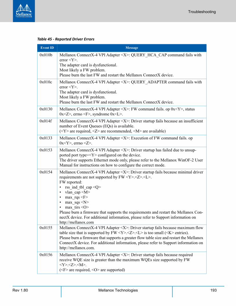
Troubleshooting
Rev 1.80 193Mellanox Technologies
0x010b Mellanox ConnectX-4 VPI Adapter <X>: QUERY_HCA_CAP command fails with error <Y>.The adapter card is dysfunctional.Most likely a FW problem.Please burn the last FW and restart the Mellanox ConnectX device.
0x010c Mellanox ConnectX-4 VPI Adapter <X>: QUERY_ADAPTER command fails with error <Y>.The adapter card is dysfunctional.Most likely a FW problem.Please burn the last FW and restart the Mellanox ConnectX device.
0x0130 Mellanox ConnectX-4 VPI Adapter <X>: FW command fails. op 0x<Y>, status 0x<Z>, errno <F>, syndrome 0x<L>.
0x014f Mellanox ConnectX-4 VPI Adapter <X>: Driver startup fails because an insufficient number of Event Queues (EQs) is available.(<Y> are required, <Z> are recommended, <M> are available)
0x0133 Mellanox ConnectX-4 VPI Adapter <X>: Execution of FW command fails. op 0x<Y>, errno <Z>.
0x0153 Mellanox ConnectX-4 VPI Adapter <X>: Driver startup has failed due to unsup-ported port type=<Y> configured on the device.The driver supports Ethernet mode only, please refer to the Mellanox WinOF-2 User Manual for instructions on how to configure the correct mode.
0x0154 Mellanox ConnectX-4 VPI Adapter <X>: Driver startup fails because minimal driver requirements are not supported by FW <Y>.<Z>.<L>. FW reported:• rss_ind_tbl_cap <Q>• vlan_cap <M>• max_rqs <F>• max_sqs <N>• max_tirs <O>Please burn a firmware that supports the requirements and restart the Mellanox Con-nectX device. For additional information, please refer to Support information on http://mellanox.com
0x0155 Mellanox ConnectX-4 VPI Adapter <X>: Driver startup fails because maximum flow table size that is supported by FW <Y>.<Z>.<L> is too small (<K> entries).Please burn a firmware that supports a greater flow table size and restart the Mellanox ConnectX device. For additional information, please refer to Support information on http://mellanox.com.
0x0156 Mellanox ConnectX-4 VPI Adapter <X>: Driver startup fails because required receive WQE size is greater than the maximum WQEs size supported by FW <Y>.<Z>.<M>.(<F> are required, <O> are supported)
Table 45 - Reported Driver Errors
Event ID Message
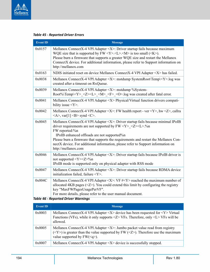
Rev 1.80194 Mellanox Technologies
0x0157 Mellanox ConnectX-4 VPI Adapter <X>: Driver startup fails because maximum WQE size that is supported by FW <Y>.<L>.<M> is too small (<K>).Please burn a firmware that supports a greater WQE size and restart the Mellanox ConnectX device. For additional information, please refer to Support information on http://mellanox.com
0x0163 NDIS initiated reset on device Mellanox ConnectX-4 VPI Adapter <X> has failed.
0x0038 Mellanox ConnectX-4 VPI Adapter <X>: mstdump SystemRoot\Temp\<Y>.log was created after a timeout on RxQueue.
0x0039 Mellanox ConnectX-4 VPI Adapter <X>: mstdump %System-Root%\Temp\<Y>_<Z><L>_<M>_<F>_<O>.log was created after fatal error.
0x0041 Mellanox ConnectX-4 VPI Adapter <X> Physical/Virtual function drivers compati-bility issue <Y>.
0x0042 Mellanox ConnectX-4 VPI Adapter <X>: FW health report - ver <Y>, hw <Z>, callra <A>, var[1] <B> synd <C>.
0x0045 Mellanox ConnectX-4 VPI Adapter <X>: Driver startup fails because minimal IPoIB driver requirements are not supported by FW <Y>_<Z><L>.%nFW reported:%n IPoIB enhanced offloads are not supported%nPlease burn a firmware that supports the requirements and restart the Mellanox Con-nectX device. For additional information, please refer to Support information on http://mellanox.com
0x0046 Mellanox ConnectX-4 VPI Adapter <X>: Driver startup fails because IPoIB driver is not supported <Y><Z>%nIPoIB mode is supported only on physical adapter with RSS mode
0x0047 Mellanox ConnectX-4 VPI Adapter <X>: Driver startup fails because RDMA device initialization failed, failure <Y>.
0x004C Mellanox ConnectX-4 VPI Adapter <X>: VF #<Y> reached the maximum number of allocated 4KB pages (<Z>). You could extend this limit by configuring the registry key "MaxFWPagesUsagePerVF".For more details, please refer to the user manual document.
Table 46 - Reported Driver Warnings
Event ID Message
0x0003 Mellanox ConnectX-4 VPI Adapter <X> device has been requested for <Y> Virtual Functions (VFs), while it only supports <Z> VFs. Therefore, only <L> VFs will be allowed.
0x0005 Mellanox ConnectX-4 VPI Adapter <X>: Jumbo packet value read from registry (<Y>) is greater than the value supported by FW (<Z>). Therefore use the maximum value supported by FW(<q>).
0x0007 Mellanox ConnectX-4 VPI Adapter <X> device is successfully stopped.
Table 45 - Reported Driver Errors
Event ID Message
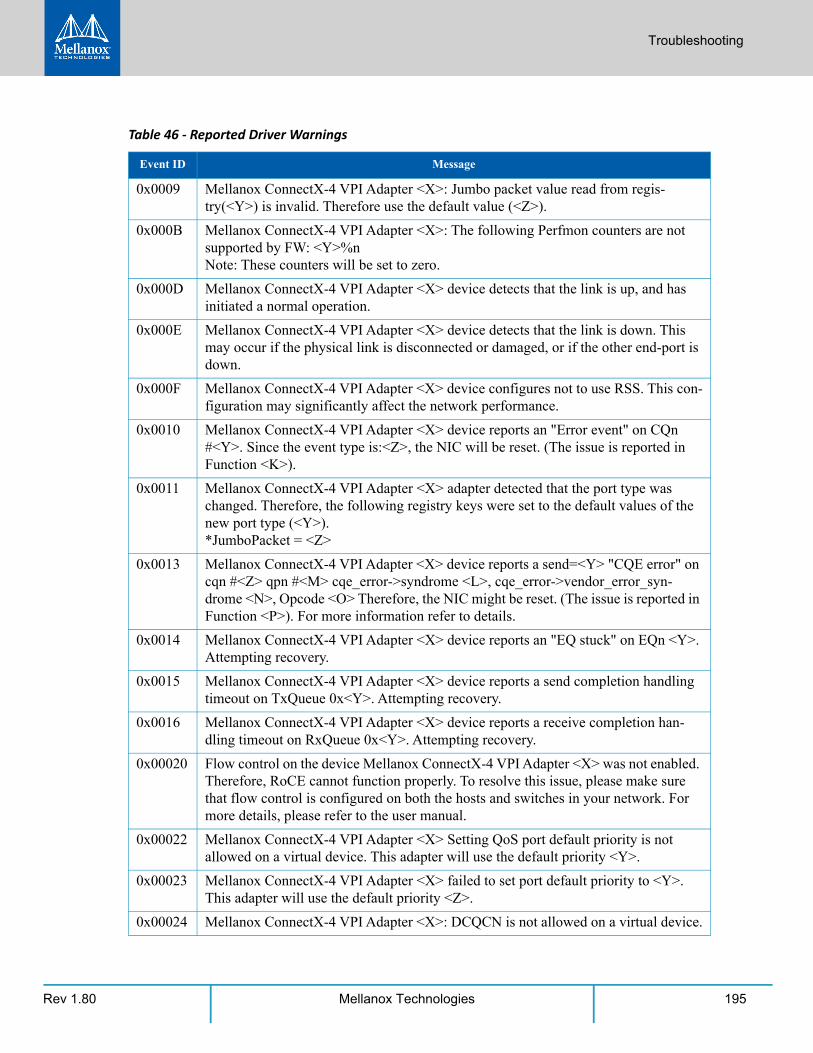
Troubleshooting
Rev 1.80 195Mellanox Technologies
0x0009 Mellanox ConnectX-4 VPI Adapter <X>: Jumbo packet value read from regis-try(<Y>) is invalid. Therefore use the default value (<Z>).
0x000B Mellanox ConnectX-4 VPI Adapter <X>: The following Perfmon counters are not supported by FW: <Y>%nNote: These counters will be set to zero.
0x000D Mellanox ConnectX-4 VPI Adapter <X> device detects that the link is up, and has initiated a normal operation.
0x000E Mellanox ConnectX-4 VPI Adapter <X> device detects that the link is down. This may occur if the physical link is disconnected or damaged, or if the other end-port is down.
0x000F Mellanox ConnectX-4 VPI Adapter <X> device configures not to use RSS. This con-figuration may significantly affect the network performance.
0x0010 Mellanox ConnectX-4 VPI Adapter <X> device reports an "Error event" on CQn #<Y>. Since the event type is:<Z>, the NIC will be reset. (The issue is reported in Function <K>).
0x0011 Mellanox ConnectX-4 VPI Adapter <X> adapter detected that the port type was changed. Therefore, the following registry keys were set to the default values of the new port type (<Y>).*JumboPacket = <Z>
0x0013 Mellanox ConnectX-4 VPI Adapter <X> device reports a send=<Y> "CQE error" on cqn #<Z> qpn #<M> cqe_error->syndrome <L>, cqe_error->vendor_error_syn-drome <N>, Opcode <O> Therefore, the NIC might be reset. (The issue is reported in Function <P>). For more information refer to details.
0x0014 Mellanox ConnectX-4 VPI Adapter <X> device reports an "EQ stuck" on EQn <Y>. Attempting recovery.
0x0015 Mellanox ConnectX-4 VPI Adapter <X> device reports a send completion handling timeout on TxQueue 0x<Y>. Attempting recovery.
0x0016 Mellanox ConnectX-4 VPI Adapter <X> device reports a receive completion han-dling timeout on RxQueue 0x<Y>. Attempting recovery.
0x00020 Flow control on the device Mellanox ConnectX-4 VPI Adapter <X> was not enabled. Therefore, RoCE cannot function properly. To resolve this issue, please make sure that flow control is configured on both the hosts and switches in your network. For more details, please refer to the user manual.
0x00022 Mellanox ConnectX-4 VPI Adapter <X> Setting QoS port default priority is not allowed on a virtual device. This adapter will use the default priority <Y>.
0x00023 Mellanox ConnectX-4 VPI Adapter <X> failed to set port default priority to <Y>. This adapter will use the default priority <Z>.
0x00024 Mellanox ConnectX-4 VPI Adapter <X>: DCQCN is not allowed on a virtual device.
Table 46 - Reported Driver Warnings
Event ID Message
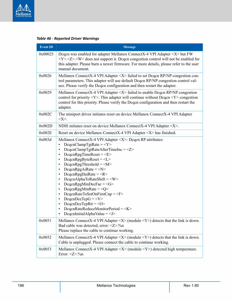
Rev 1.80196 Mellanox Technologies
0x00025 Dcqcn was enabled for adapter Mellanox ConnectX-4 VPI Adapter <X> but FW <Y>.<Z>.<W> does not support it. Dcqcn congestion control will not be enabled for this adapter. Please burn a newer firmware. For more details, please refer to the user manual document.
0x0026 Mellanox ConnectX-4 VPI Adapter <X> failed to set Dcqcn RP/NP congestion con-trol parameters. This adapter will use default Dcqcn RP/NP congestion control val-ues. Please verify the Dcqcn configuration and then restart the adapter.
0x0029 Mellanox ConnectX-4 VPI Adapter <X> failed to enable Dcqcn RP/NP congestion control for priority <Y>. This adapter will continue without Dcqcn <Y> congestion control for this priority. Please verify the Dcqcn configuration and then restart the adapter.
0x002C The miniport driver initiates reset on device Mellanox ConnectX-4 VPI Adapter <X>.
0x002D NDIS initiates reset on device Mellanox ConnectX-4 VPI Adapter <X>.
0x002E Reset on device Mellanox ConnectX-4 VPI Adapter <X> has finished.
0x003d Mellanox ConnectX-4 VPI Adapter <X>: Dcqcn RP attributes:• DcqcnClampTgtRate = <Y>• DcqcnClampTgtRateAfterTimeInc = <Z>• DcqcnRpgTimeReset = <E>• DcqcnRpgByteReset = <L>• DcqcnRpgThreshold = <M>• DcqcnRpgAiRate = <N>• DcqcnRpgHaiRate = <R>• DcqcnAlphaToRateShift = <W>• DcqcnRpgMinDecFac = <G>• DcqcnRpgMinRate = <Q>• DcqcnRateToSetOnFirstCnp = <F>• DcqcnDceTcpG = <V>• DcqcnDceTcpRtt = <O>• DcqcnRateReduceMonitorPeriod = <K>• DcqcnInitialAlphaValue = <J>
0x0051 Mellanox ConnectX-4 VPI Adapter <X> (module <Y>) detects that the link is down. Bad cable was detected, error: <Z>.%nPlease replace the cable to continue working.
0x0052 Mellanox ConnectX-4 VPI Adapter <X> (module <Y>) detects that the link is down. Cable is unplugged. Please connect the cable to continue working.
0x0053 Mellanox ConnectX-4 VPI Adapter <X> (module <Y>) detected high temperature. Error: <Z>.%n
Table 46 - Reported Driver Warnings
Event ID Message
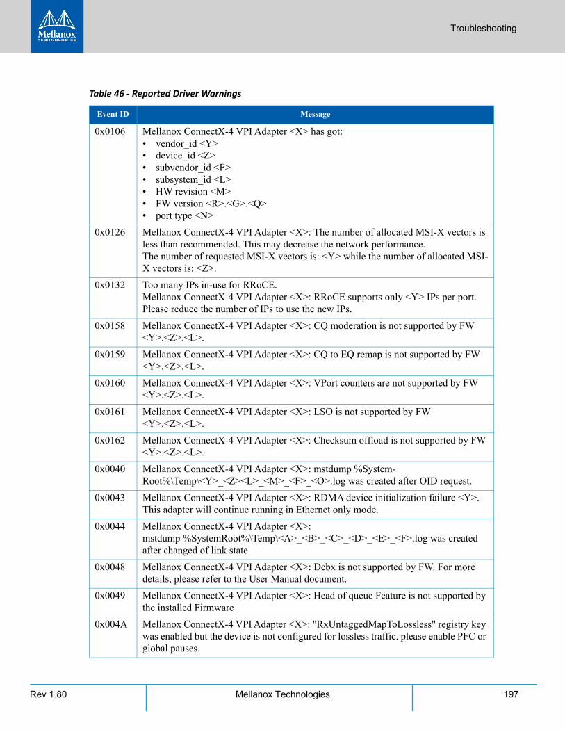
Troubleshooting
Rev 1.80 197Mellanox Technologies
0x0106 Mellanox ConnectX-4 VPI Adapter <X> has got:• vendor_id <Y>• device_id <Z>• subvendor_id <F>• subsystem_id <L>• HW revision <M>• FW version <R>.<G>.<Q>• port type <N>
0x0126 Mellanox ConnectX-4 VPI Adapter <X>: The number of allocated MSI-X vectors is less than recommended. This may decrease the network performance.The number of requested MSI-X vectors is: <Y> while the number of allocated MSI-X vectors is: <Z>.
0x0132 Too many IPs in-use for RRoCE.Mellanox ConnectX-4 VPI Adapter <X>: RRoCE supports only <Y> IPs per port.Please reduce the number of IPs to use the new IPs.
0x0158 Mellanox ConnectX-4 VPI Adapter <X>: CQ moderation is not supported by FW <Y>.<Z>.<L>.
0x0159 Mellanox ConnectX-4 VPI Adapter <X>: CQ to EQ remap is not supported by FW <Y>.<Z>.<L>.
0x0160 Mellanox ConnectX-4 VPI Adapter <X>: VPort counters are not supported by FW <Y>.<Z>.<L>.
0x0161 Mellanox ConnectX-4 VPI Adapter <X>: LSO is not supported by FW <Y>.<Z>.<L>.
0x0162 Mellanox ConnectX-4 VPI Adapter <X>: Checksum offload is not supported by FW <Y>.<Z>.<L>.
0x0040 Mellanox ConnectX-4 VPI Adapter <X>: mstdump %System-Root%\Temp\<Y>_<Z><L>_<M>_<F>_<O>.log was created after OID request.
0x0043 Mellanox ConnectX-4 VPI Adapter <X>: RDMA device initialization failure <Y>. This adapter will continue running in Ethernet only mode.
0x0044 Mellanox ConnectX-4 VPI Adapter <X>:mstdump %SystemRoot%\Temp\<A>_<B>_<C>_<D>_<E>_<F>.log was created after changed of link state.
0x0048 Mellanox ConnectX-4 VPI Adapter <X>: Dcbx is not supported by FW. For more details, please refer to the User Manual document.
0x0049 Mellanox ConnectX-4 VPI Adapter <X>: Head of queue Feature is not supported by the installed Firmware
0x004A Mellanox ConnectX-4 VPI Adapter <X>: "RxUntaggedMapToLossless" registry key was enabled but the device is not configured for lossless traffic. please enable PFC or global pauses.
Table 46 - Reported Driver Warnings
Event ID Message
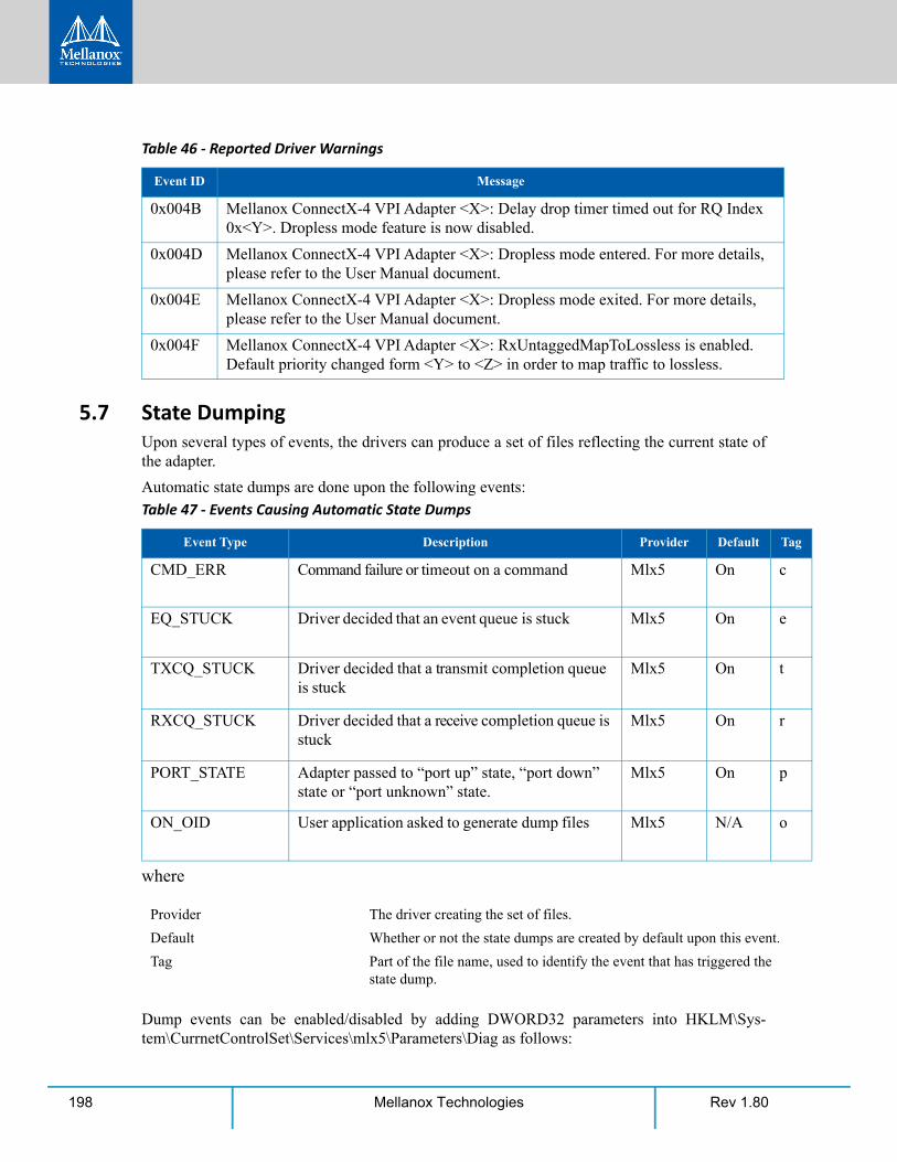
Rev 1.80198 Mellanox Technologies
5.7 State DumpingUpon several types of events, the drivers can produce a set of files reflecting the current state of the adapter.
Automatic state dumps are done upon the following events:
where
Dump events can be enabled/disabled by adding DWORD32 parameters into HKLM\Sys-tem\CurrnetControlSet\Services\mlx5\Parameters\Diag as follows:
0x004B Mellanox ConnectX-4 VPI Adapter <X>: Delay drop timer timed out for RQ Index 0x<Y>. Dropless mode feature is now disabled.
0x004D Mellanox ConnectX-4 VPI Adapter <X>: Dropless mode entered. For more details, please refer to the User Manual document.
0x004E Mellanox ConnectX-4 VPI Adapter <X>: Dropless mode exited. For more details, please refer to the User Manual document.
0x004F Mellanox ConnectX-4 VPI Adapter <X>: RxUntaggedMapToLossless is enabled. Default priority changed form <Y> to <Z> in order to map traffic to lossless.
Table 47 - Events Causing Automatic State Dumps
Event Type Description Provider Default Tag
CMD_ERR Command failure or timeout on a command Mlx5 On c
EQ_STUCK Driver decided that an event queue is stuck Mlx5 On e
TXCQ_STUCK Driver decided that a transmit completion queue is stuck
Mlx5 On t
RXCQ_STUCK Driver decided that a receive completion queue is stuck
Mlx5 On r
PORT_STATE Adapter passed to “port up” state, “port down” state or “port unknown” state.
Mlx5 On p
ON_OID User application asked to generate dump files Mlx5 N/A o
Provider The driver creating the set of files.
Default Whether or not the state dumps are created by default upon this event.
Tag Part of the file name, used to identify the event that has triggered the state dump.
Table 46 - Reported Driver Warnings
Event ID Message
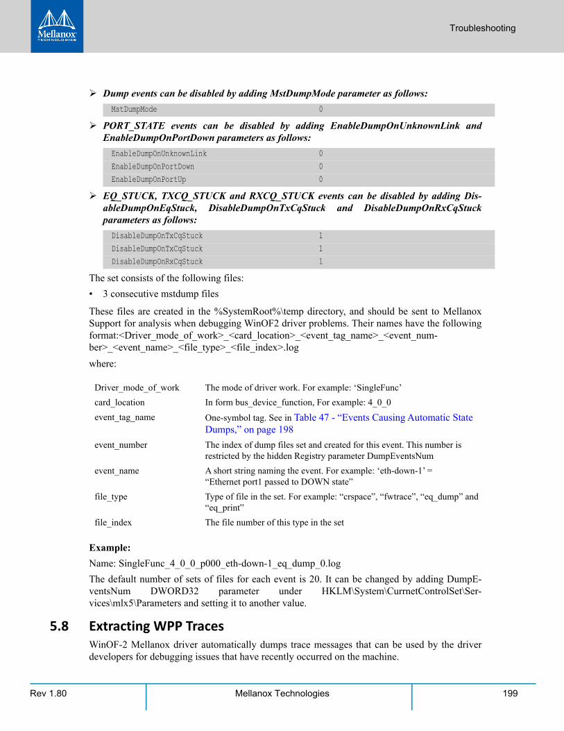
Troubleshooting
Rev 1.80 199Mellanox Technologies
Dump events can be disabled by adding MstDumpMode parameter as follows:
PORT_STATE events can be disabled by adding EnableDumpOnUnknownLink and EnableDumpOnPortDown parameters as follows:
EQ_STUCK, TXCQ_STUCK and RXCQ_STUCK events can be disabled by adding Dis-ableDumpOnEqStuck, DisableDumpOnTxCqStuck and DisableDumpOnRxCqStuck parameters as follows:
The set consists of the following files:
• 3 consecutive mstdump files
These files are created in the %SystemRoot%\temp directory, and should be sent to Mellanox Support for analysis when debugging WinOF2 driver problems. Their names have the following format:<Driver_mode_of_work>_<card_location>_<event_tag_name>_<event_num- ber>_<event_name>_<file_type>_<file_index>.log
where:
Example:
Name: SingleFunc_4_0_0_p000_eth-down-1_eq_dump_0.log
The default number of sets of files for each event is 20. It can be changed by adding DumpE-ventsNum DWORD32 parameter under HKLM\System\CurrnetControlSet\Ser-vices\mlx5\Parameters and setting it to another value.
5.8 Extracting WPP TracesWinOF-2 Mellanox driver automatically dumps trace messages that can be used by the driver developers for debugging issues that have recently occurred on the machine.
MstDumpMode 0
EnableDumpOnUnknownLink 0EnableDumpOnPortDown 0EnableDumpOnPortUp 0
DisableDumpOnTxCqStuck 1DisableDumpOnTxCqStuck 1DisableDumpOnRxCqStuck 1
Driver_mode_of_work The mode of driver work. For example: ‘SingleFunc’
card_location In form bus_device_function, For example: 4_0_0
event_tag_name One-symbol tag. See in Table 47 - “Events Causing Automatic State Dumps,” on page 198
event_number The index of dump files set and created for this event. This number is restricted by the hidden Registry parameter DumpEventsNum
event_name A short string naming the event. For example: ‘eth-down-1’ = “Ethernet port1 passed to DOWN state”
file_type Type of file in the set. For example: “crspace”, “fwtrace”, “eq_dump” and “eq_print”
file_index The file number of this type in the set
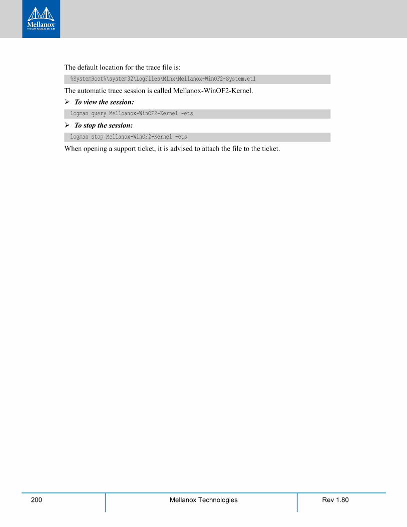
Rev 1.80200 Mellanox Technologies
The default location for the trace file is:
The automatic trace session is called Mellanox-WinOF2-Kernel.
To view the session:
To stop the session:
When opening a support ticket, it is advised to attach the file to the ticket.
%SystemRoot%\system32\LogFiles\Mlnx\Mellanox-WinOF2-System.etl
logman query Melloanox-WinOF2-Kernel -ets
logman stop Mellanox-WinOF2-Kernel -ets

Troubleshooting
Rev 1.80 201Mellanox Technologies

Rev 1.80202 Mellanox Technologies

Rev 1.80 203Mellanox Technologies
Appendix A: NVGRE Configuration Scripts ExamplesThe setup is as follow for both examples below:
A.1 Adding NVGRE Configuration to Host 14 ExampleThe following is an example of adding NVGRE to Host 14.
Hypervisor host14 = "Port1", 192.168.20.114/24 VM on host14 = host14-005, 172.16.14.5/16, Mac 00155D720100 VM on host14 = host14-006, 172.16.14.6/16, Mac 00155D720101Hypervisor host15 = "Port1", 192.168.20.115/24 VM on host15 = host15-005, 172.16.15.5/16, Mac 00155D730100 VM on host15 = host15-006, 172.16.15.6/16, Mac 00155D730101
# On both sides# vSwitch create command
# Note, that vSwitch configuration is persistent, no need to configure it after each reboot New-VMSwitch "VSwMLNX" -NetAdapterName "Port1" -AllowManagementOS $true # Shut down VMsStop-VM -Name "host14-005" -Force -Confirm Stop-VM -Name "host14-006" -Force -Confirm # Connect VM to vSwitch (maybe you have to switch off VM before), doing manual does also
work# Connect-VMNetworkAdapter -VMName " host14-005" -SwitchName "VSwMLNX" Add-VMNetworkAdapter -VMName "host14-005" -SwitchName "VSwMLNX" -StaticMacAddress
"00155D720100"Add-VMNetworkAdapter -VMName "host14-006" -SwitchName "VSwMLNX" -StaticMacAddress
"00155D720101"
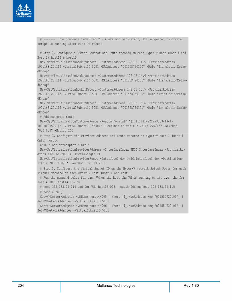
Rev 1.80204 Mellanox Technologies
# ------- The commands from Step 2 - 4 are not persistent, Its suggested to create script is running after each OS reboot # Step 2. Configure a Subnet Locator and Route records on each Hyper-V Host (Host 1 and
Host 2) host14 & host15New-NetVirtualizationLookupRecord -CustomerAddress 172.16.14.5 -ProviderAddress
192.168.20.114 -VirtualSubnetID 5001 -MACAddress "00155D720100" -Rule "TranslationMetho-dEncap"New-NetVirtualizationLookupRecord -CustomerAddress 172.16.14.6 -ProviderAddress
192.168.20.114 -VirtualSubnetID 5001 -MACAddress "00155D720101" -Rule "TranslationMetho-dEncap"New-NetVirtualizationLookupRecord -CustomerAddress 172.16.15.5 -ProviderAddress
192.168.20.115 -VirtualSubnetID 5001 -MACAddress "00155D730100" -Rule "TranslationMetho-dEncap"New-NetVirtualizationLookupRecord -CustomerAddress 172.16.15.6 -ProviderAddress
192.168.20.115 -VirtualSubnetID 5001 -MACAddress "00155D730101" -Rule "TranslationMetho-dEncap"# Add customer routeNew-NetVirtualizationCustomerRoute -RoutingDomainID "{11111111-2222-3333-4444-
000000005001}" -VirtualSubnetID "5001" -DestinationPrefix "172.16.0.0/16" -NextHop "0.0.0.0" -Metric 255# Step 3. Configure the Provider Address and Route records on Hyper-V Host 1 (Host 1
Only) host14$NIC = Get-NetAdapter "Port1"New-NetVirtualizationProviderAddress -InterfaceIndex $NIC.InterfaceIndex -ProviderAd-
dress 192.168.20.114 -PrefixLength 24New-NetVirtualizationProviderRoute -InterfaceIndex $NIC.InterfaceIndex -Destination-
Prefix "0.0.0.0/0" -NextHop 192.168.20.1# Step 5. Configure the Virtual Subnet ID on the Hyper-V Network Switch Ports for each
Virtual Machine on each Hyper-V Host (Host 1 and Host 2)# Run the command below for each VM on the host the VM is running on it, i.e. the for
host14-005, host14-006 on # host 192.168.20.114 and for VMs host15-005, host15-006 on host 192.168.20.115# host14 onlyGet-VMNetworkAdapter -VMName host14-005 | where {$_.MacAddress –eq "00155D720100"} |
Set-VMNetworkAdapter -VirtualSubnetID 5001 Get-VMNetworkAdapter -VMName host14-006 | where {$_.MacAddress –eq "00155D720101"} |
Set-VMNetworkAdapter -VirtualSubnetID 5001
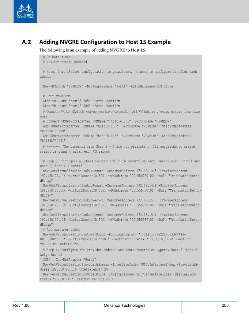
Rev 1.80 205Mellanox Technologies
A.2 Adding NVGRE Configuration to Host 15 ExampleThe following is an example of adding NVGRE to Host 15.
# On both sides# vSwitch create command
# Note, that vSwitch configuration is persistent, no need to configure it after each reboot New-VMSwitch "VSwMLNX" -NetAdapterName "Port1" -AllowManagementOS $true
# Shut down VMsStop-VM -Name "host15-005" -Force -Confirm Stop-VM -Name "host15-006" -Force -Confirm # Connect VM to vSwitch (maybe you have to switch off VM before), doing manual does also
work# Connect-VMNetworkAdapter -VMName " host14-005" -SwitchName "VSwMLNX" Add-VMNetworkAdapter -VMName "host15-005" -SwitchName "VSwMLNX" -StaticMacAddress
"00155D730100"Add-VMNetworkAdapter -VMName "host15-006" -SwitchName "VSwMLNX" -StaticMacAddress
"00155D730101"# ------- The commands from Step 2 - 4 are not persistent, Its suggested to create
script is running after each OS reboot # Step 2. Configure a Subnet Locator and Route records on each Hyper-V Host (Host 1 and
Host 2) host14 & host15New-NetVirtualizationLookupRecord -CustomerAddress 172.16.14.5 -ProviderAddress
192.168.20.114 -VirtualSubnetID 5001 -MACAddress "00155D720100" -Rule "TranslationMetho-dEncap"New-NetVirtualizationLookupRecord -CustomerAddress 172.16.14.6 -ProviderAddress
192.168.20.114 -VirtualSubnetID 5001 -MACAddress "00155D720101" -Rule "TranslationMetho-dEncap"New-NetVirtualizationLookupRecord -CustomerAddress 172.16.15.5 -ProviderAddress
192.168.20.115 -VirtualSubnetID 5001 -MACAddress "00155D730100" -Rule "TranslationMetho-dEncap"New-NetVirtualizationLookupRecord -CustomerAddress 172.16.15.6 -ProviderAddress
192.168.20.115 -VirtualSubnetID 5001 -MACAddress "00155D730101" -Rule "TranslationMetho-dEncap"# Add customer routeNew-NetVirtualizationCustomerRoute -RoutingDomainID "{11111111-2222-3333-4444-
000000005001}" -VirtualSubnetID "5001" -DestinationPrefix "172.16.0.0/16" -NextHop "0.0.0.0" -Metric 255# Step 4. Configure the Provider Address and Route records on Hyper-V Host 2 (Host 2
Only) host15 $NIC = Get-NetAdapter "Port1"New-NetVirtualizationProviderAddress -InterfaceIndex $NIC.InterfaceIndex -ProviderAd-
dress 192.168.20.115 -PrefixLength 24New-NetVirtualizationProviderRoute -InterfaceIndex $NIC.InterfaceIndex -Destination-
Prefix "0.0.0.0/0" -NextHop 192.168.20.1
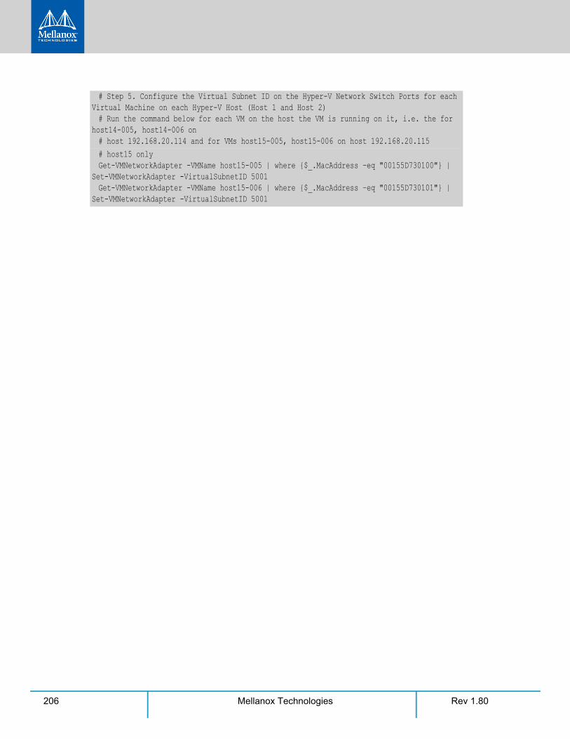
Rev 1.80206 Mellanox Technologies
# Step 5. Configure the Virtual Subnet ID on the Hyper-V Network Switch Ports for each Virtual Machine on each Hyper-V Host (Host 1 and Host 2)# Run the command below for each VM on the host the VM is running on it, i.e. the for
host14-005, host14-006 on # host 192.168.20.114 and for VMs host15-005, host15-006 on host 192.168.20.115# host15 onlyGet-VMNetworkAdapter -VMName host15-005 | where {$_.MacAddress –eq "00155D730100"} |
Set-VMNetworkAdapter -VirtualSubnetID 5001 Get-VMNetworkAdapter -VMName host15-006 | where {$_.MacAddress –eq "00155D730101"} |
Set-VMNetworkAdapter -VirtualSubnetID 5001
Rev 1.80 207Mellanox Technologies
Appendix B: Windows MPI (MS-MPI)
B.1 OverviewMessage Passing Interface (MPI) provides virtual topology, synchronization, and communication functionality between a set of processes. MPI enables running one process on several hosts. With MPI you can run one process on several hosts.
• Windows MPI run over the following protocols:
• Sockets (Ethernet or IPoIB)
• Network Direct (ND) Ethernet and InfiniBand
B.1.1 System Requirements• Install HPC (Build: 4.0.3906.0).
• Validate traffic (ping) between the whole MPI Hosts.
• Every MPI client need to run smpd process which open the mpi channel.
• MPI Initiator Server need to run: mpiexec. If the initiator is also client it should also run smpd.
B.2 Running MPI Step 1. Run the following command on each mpi client.
Step 2. Install ND provider on each MPI client in MPI ND.
Step 3. Run the following command on MPI server.
B.3 Directing MSMPI TrafficDirecting MPI traffic to a specific QoS priority may delayed due to:
• Except for NetDirectPortMatchCondition, the QoS powershell CmdLet for NetworkDi-rect traffic does not support port range. Therefore, NetwrokDirect traffic cannot be directed to ports 1-65536.
• The MSMPI directive to control the port range (namely: MPICH_PORT_RANGE 3000,3030) is not working for ND, and MSMPI chose a random port.
start smpd -d -p <port>
mpiexec.exe -p <smpd_port> -hosts <num_of_hosts> <hosts_ip_list> -env MPICH_NETMASK <network_ip/subnet> -env MPICH_ND_ZCOPY_THRESHOLD -1 -env MPICH_DISABLE_ND <0/1> -env MPICH_DISABLE_SOCK <0/1> -affinity <process>
Rev 1.80208 Mellanox Technologies
B.4 Running MSMPI on the Desired Priority Step 1. Set the default QoS policy to be the desired priority (Note: this prio should be lossless all
the way in the switches*)
Step 2. Set SMB policy to a desired priority only if SMD Traffic running.
Step 3. [Recommended] Direct ALL TCP/UDP traffic to a lossy priority by using the “IPProtocol-MatchCondition”.
Arista switches forwards the pcp bits (e.g. 802.1p priority within the vlan tag) from ingress to egress to enable any two End-Nodes in the fabric as to maintain the priority along the route.
In this case the packet from the sender goes out with priority X and reaches the far end-node with the same priority X.
To force MSMPI to work over ND and not over sockets, add the following in mpiexec com-mand:
B.5 Configuring MPI Step 1. Configure all the hosts in the cluster with identical PFC (see the PFC example below).
Step 2. Run the WHCK ND based traffic tests to Check PFC (ndrping, ndping, ndrpingpong, ndpingpong).
Step 3. Validate PFC counters, during the run-time of ND tests, with “Mellanox Adapter QoS Counters” in the perfmon.
Step 4. Install the same version of HPC Pack in the entire cluster. NOTE: Version mismatch in HPC Pack 2012 can cause MPI to hung.
Step 5. Validate the MPI base infrastructure with simple commands, such as “hostname”.
B.5.1 PFC Example In the example below, ND and NDK go to priority 3 that configures no-drop in the switches. The TCP/UDP traffic directs ALL traffic to priority 1.
• Install dcbx.
TCP is being used for MPI control channel (smpd), while UDP is being used for other services such as remote-desktop.
The priority should be losslessin the switches
-env MPICH_DISABLE_ND 0 -env MPICH_DISABLE_SOCK 1
Install-WindowsFeature Data-Center-Bridging
Rev 1.80 209Mellanox Technologies
• Remove the entire previous settings.
• Set the DCBX Willing parameter to false as Mellanox drivers do not support this feature
• Create a Quality of Service (QoS) policy and tag each type of traffic with the relevant priority. In this example we used TCP/UDP priority 1, ND/NDK priority 3.
• Enable PFC on priority 3.
• Disable Priority Flow Control (PFC) for all other priorities except for 3.
• Enable QoS on the relevant interface.
B.5.2 Running MPI Command Examples• Running MPI pallas test over ND.
• Running MPI pallas test over ETH.
Remove-NetQosTrafficClassRemove-NetQosPolicy -Confirm:$False
Set-NetQosDcbxSetting -Willing 0
New-NetQosPolicy “SMB" -NetDirectPortMatchCondition 445 -PriorityValue8021Action 3New-NetQosPolicy “DEFAULT" -Default -PriorityValue8021Action 3New-NetQosPolicy “TCP" -IPProtocolMatchCondition TCP -PriorityValue8021Action1New-NetQosPolicy “UDP" -IPProtocolMatchCondition UDP -PriorityValue8021Action 1
Enable-NetQosFlowControl 3
Disable-NetQosFlowControl 0,1,2,4,5,6,7
Enable-netadapterqos -Name
> mpiexec.exe -p 19020 -hosts 4 11.11.146.101 11.21.147.101 11.21.147.51 11.11.145.101 -env MPICH_NETMASK 11.0.0.0/255.0.0.0 -env MPICH_ND_ZCOPY_THRESHOLD -1 -env MPICH_DISABLE_ND 0 -env MPICH_DISABLE_SOCK 1 -affinity c:\\test1.exe
> exempiexec.exe -p 19020 -hosts 4 11.11.146.101 11.21.147.101 11.21.147.5111.11.145.101 -env MPICH_NETMASK 11.0.0.0/255.0.0.0 -env MPICH_ND_ZCOPY_THRESHOLD -1 -env MPICH_DISABLE_ND 1 -envMPICH_DISABLE_SOCK 0 -affinity c:\\test1.exe