Embed Size (px)
Citation preview
Page 1
Melody Smart Manual
Manual
Melody-Smart
Melody-Smart 2.6.0 Manual Rev. E
Features
Configurable Bluetooth Low Energy (BLE) software
Low power consumption: <13µA connected, <5µA in Deep Sleep
Can be controlled over UART or via GPIO interfaces
Connects to: iOS application, Android 4.3+ BLE devices, or any other BLE enabled device
Profiles supported: proprietary and highly-customisable Melody-Smart profile, includes Battery service,
and Melody-Smart service1
Highly flexible and configurable interface
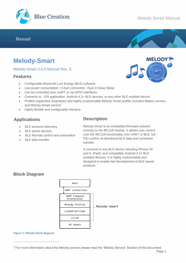
Block Diagram
Figure 1: Melody block diagram
1 For more information about the Melody service please read the ‘Melody Service’ Section of this document.
Applications
BLE sensors/ telemetry
BLE sports devices
BLE Remote control and automation
BLE data transfer
Description
Melody-Smart is an embedded firmware solution
running on the BC118 module. It allows user control
over the MC118 functionality over UART or BLE, full
PIO control, bi-directional BLE data and command
transfer.
It connects to any BLE device including iPhone 4S
and 5, iPad3, and compatible Android 4.3+ BLE
enabled devices. It is highly customisable and
designed to enable fast development of BLE based
products
Page 2
Melody Smart Manual
Manual
Introduction Melody-Smart is an embedded firmware solution running on the BC118 module. Melody-Smart includes an
application, the Bluetooth Low-Energy protocol stack, the Melody-Smart profile and the low level firmware. It
therefore allows implementing a BLE device without any detailed knowledge of the Bluetooth standard.
Melody-Smart provides a simple high level UART command interface where the Bluetooth module can be
controlled from a host processor. Melody-Smart is configured so that the host processor can also control the
remote device by sending any customer provided commands over BLE. The remote device has full access
and control over the CSR10X1 PIO pins.
Setting Up To start you need to have:
a) BC118 Discovery Board.
Please contact [email protected] for more information.
b) A computer running a serial terminal, such as PuTTY, HyperTerminal for Windows or an equivalent
program, to communicate over the COM interface.
The CNS10020 board enumerates as a virtual COM port. Please use Device Manager to discover the port
number. By default, Melody Smart uses the following UART settings:
Baud rate : 9600bps
Data bits : 8
Stop bits : 1
Parity bit : No parity
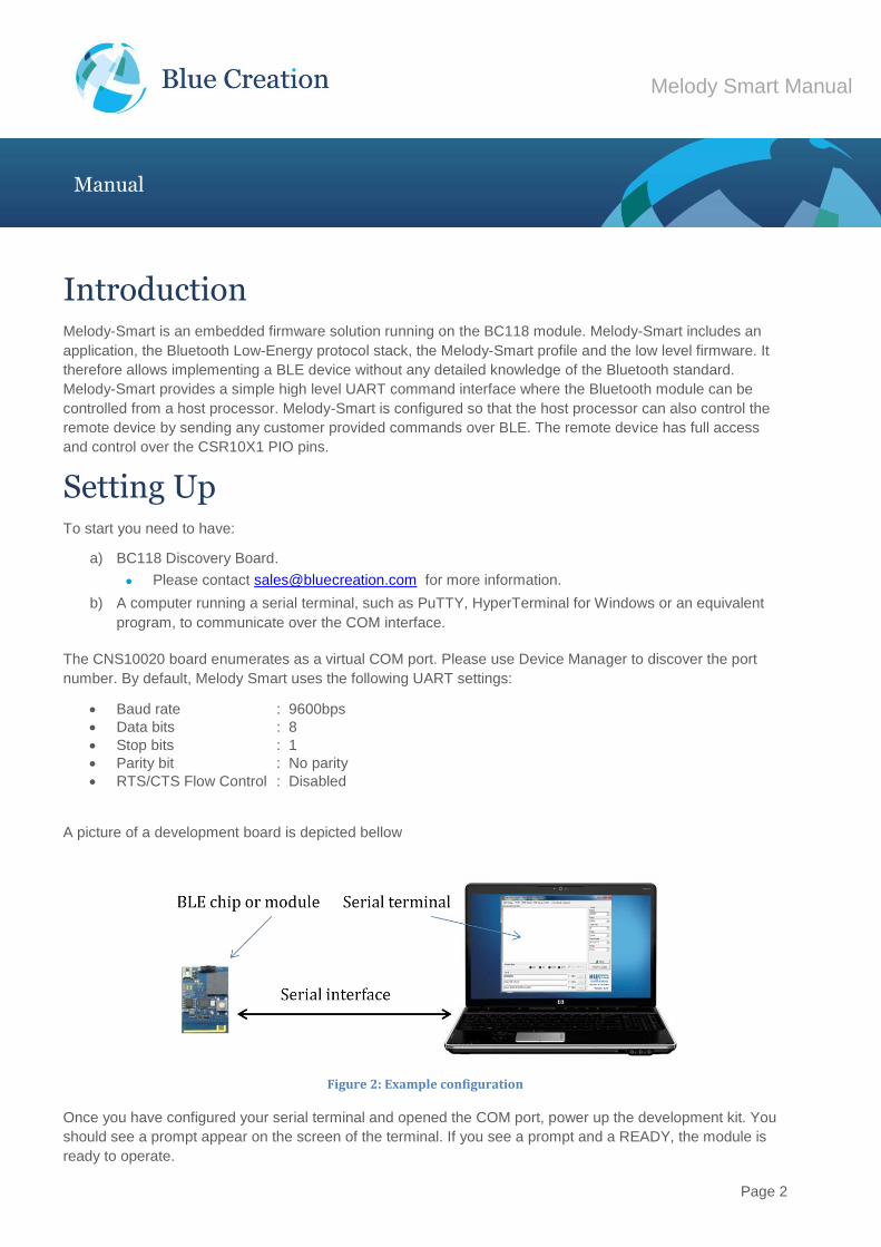
RTS/CTS Flow Control : Disabled A picture of a development board is depicted bellow
Figure 2: Example configuration
Once you have configured your serial terminal and opened the COM port, power up the development kit. You
should see a prompt appear on the screen of the terminal. If you see a prompt and a READY, the module is
ready to operate.
Page 3
Melody Smart Manual
Manual
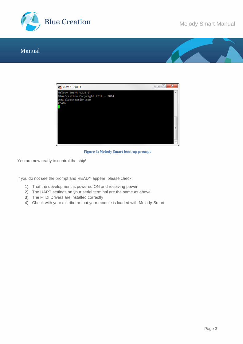
Figure 3: Melody Smart boot-up prompt
You are now ready to control the chip!
If you do not see the prompt and READY appear, please check:
1) That the development is powered ON and receiving power
2) The UART settings on your serial terminal are the same as above
3) The FTDI Drivers are installed correctly
4) Check with your distributor that your module is loaded with Melody-Smart
Page 4
Melody Smart Manual
Manual
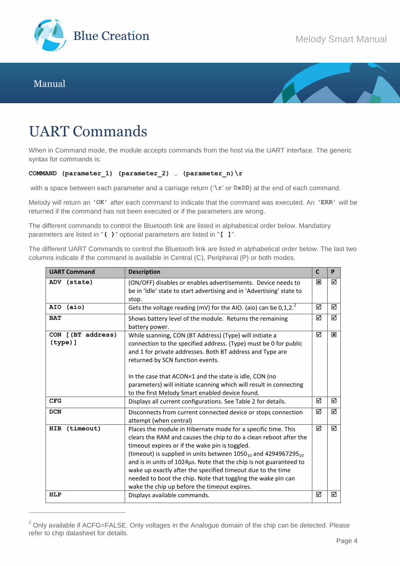
UART Commands When in Command mode, the module accepts commands from the host via the UART interface. The generic
syntax for commands is:
COMMAND (parameter_1) (parameter_2) … (parameter_n)\r
with a space between each parameter and a carriage return (‘\r’ or 0x0D) at the end of each command.
Melody will return an ‘OK’ after each command to indicate that the command was executed. An ‘ERR’ will be
returned if the command has not been executed or if the parameters are wrong.
The different commands to control the Bluetooth link are listed in alphabetical order below. Mandatory
parameters are listed in "( )" optional parameters are listed in "[ ]".
The different UART Commands to control the Bluetooth link are listed in alphabetical order below. The last two
columns indicate if the command is available in Central (C), Peripheral (P) or both modes.
UART Command Description C P
ADV (state) (ON/OFF) disables or enables advertisements. Device needs to be in ‘Idle’ state to start advertising and in ‘Advertising’ state to stop.
AIO (aio) Gets the voltage reading (mV) for the AIO. (aio) can be 0,1,2.2
BAT Shows battery level of the module. Returns the remaining battery power.
CON [(BT address)
(type)]
While scanning, CON (BT Address) (Type) will initiate a connection to the specified address. (Type) must be 0 for public and 1 for private addresses. Both BT address and Type are returned by SCN function events. In the case that ACON=1 and the state is idle, CON (no parameters) will initiate scanning which will result in connecting to the first Melody Smart enabled device found.
CFG Displays all current configurations. See Table 2 for details.
DCN Disconnects from current connected device or stops connection attempt (when central)
HIB (timeout) Places the module in Hibernate mode for a specific time. This clears the RAM and causes the chip to do a clean reboot after the timeout expires or if the wake pin is toggled. (timeout) is supplied in units between 105010 and 429496729510 and is in units of 1024µs. Note that the chip is not guaranteed to wake up exactly after the specified timeout due to the time needed to boot the chip. Note that toggling the wake pin can wake the chip up before the timeout expires.
HLP Displays available commands.
2 Only available if ACFG=FALSE. Only voltages in the Analogue domain of the chip can be detected. Please
refer to chip datasheet for details.
Page 5
Melody Smart Manual
Manual
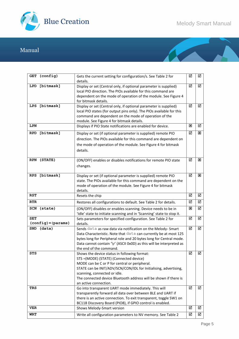
GET (config) Gets the current setting for configuration/s. See Table 2 for details.
LPD [bitmask] Display or set (Central only, if optional parameter is supplied) local PIO direction. The PIOs available for this command are dependent on the mode of operation of the module. See Figure 4 for bitmask details.
LPS [bitmask] Display or set (Central only, if optional parameter is supplied) local PIO states (for output pins only). The PIOs available for this command are dependent on the mode of operation of the module. See Figure 4 for bitmask details.
LPN Displays if PIO State notifications are enabled for device.
RPD [bitmask] Display or set (if optional parameter is supplied) remote PIO
direction. The PIOs available for this command are dependent on
the mode of operation of the module. See Figure 4 for bitmask
details.
RPN (STATE) (ON/OFF) enables or disables notifications for remote PIO state
changes.
RPS [bitmask] Display or set (if optional parameter is supplied) remote PIO state. The PIOs available for this command are dependent on the mode of operation of the module. See Figure 4 for bitmask details.
RST Resets the chip
RTR Restores all configurations to default. See Table 2 for details.
SCN (state) (ON/OFF) disables or enables scanning. Device needs to be in ‘Idle’ state to initiate scanning and in ‘Scanning’ state to stop it.
SET
(config)=(params) Sets parameters for specified configuration. See Table 2 for details.
SND (data) Sends data as raw data via notification on the Melody- Smart Data Characteristic. Note that data can currently be at most 125 bytes long for Peripheral role and 20 bytes long for Central mode. Data cannot contain ‘\r’ (ASCII 0x0D) as this will be interpreted as the end of the command.
STS Shows the device status in following format: STS =(MODE) (STATE) (Connected device) MODE can be C or P for central or peripheral. STATE can be INIT/ADV/SCN/CON/IDL for Initialising, advertising, scanning, connected or idle. The connected device Bluetooth address will be shown if there is an active connection.
TRS Go into transparent UART mode immediately. This will transparently forward all data over between BLE and UART if there is an active connection. To exit transparent, toggle SW1 on BC118 Discovery Board (PIO8), if GPIO control is enabled.
VER Shows Melody-Smart version
WRT Write all configuration parameters to NV memory. See Table 2

Page 6
Melody Smart Manual
Manual
for details.
Table 1: UART commands
Page 7
Melody Smart Manual
Manual
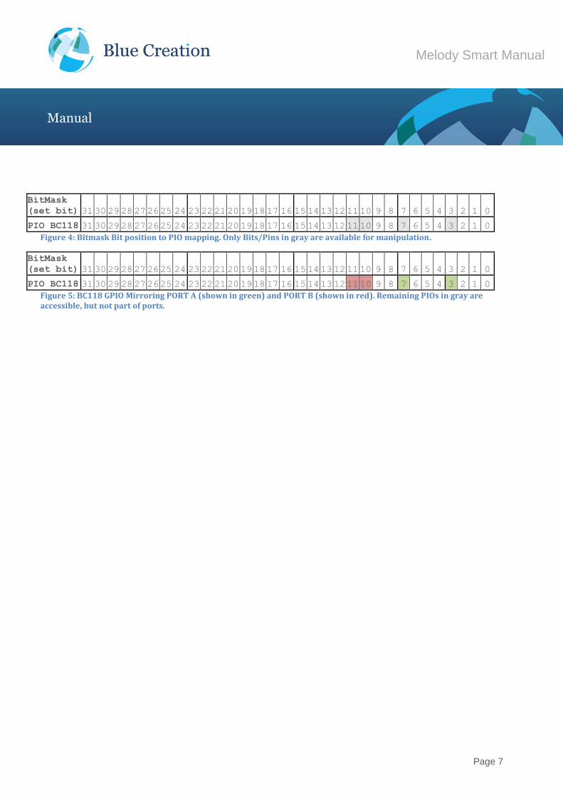
BitMask
(set bit) 31 30 29 28 27 26 25 24 23 22 21 20 19 18 17 16 15 14 13 12 11 10 9 8 7 6 5 4 3 2 1 0
PIO BC118 31 30 29 28 27 26 25 24 23 22 21 20 19 18 17 16 15 14 13 12 11 10 9 8 7 6 5 4 3 2 1 0
Figure 4: Bitmask Bit position to PIO mapping. Only Bits/Pins in gray are available for manipulation. BitMask
(set bit) 31 30 29 28 27 26 25 24 23 22 21 20 19 18 17 16 15 14 13 12 11 10 9 8 7 6 5 4 3 2 1 0
PIO BC118 31 30 29 28 27 26 25 24 23 22 21 20 19 18 17 16 15 14 13 12 11 10 9 8 7 6 5 4 3 2 1 0
Figure 5: BC118 GPIO Mirroring PORT A (shown in green) and PORT B (shown in red). Remaining PIOs in gray are accessible, but not part of ports.
Page 8
Melody Smart Manual
Manual
UART Configuration Commands and Parameters
When Melody is in Command mode, the user can configure general parameters for the module. These
parameters are stored in the RAM memory. If required, the parameters can be stored to NV memory. When
the module reboots, it will boot with the parameters that are saved to NV memory.
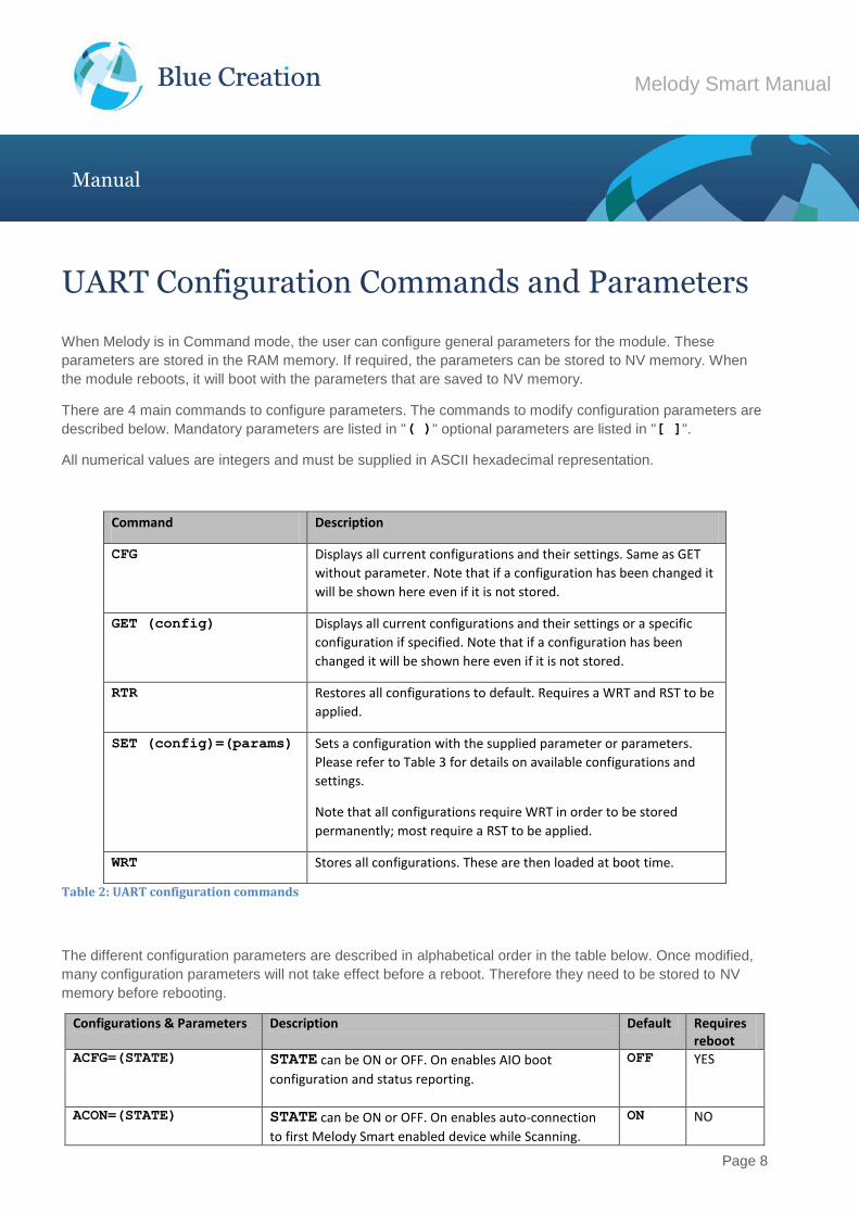
There are 4 main commands to configure parameters. The commands to modify configuration parameters are
described below. Mandatory parameters are listed in "( )" optional parameters are listed in "[ ]".
All numerical values are integers and must be supplied in ASCII hexadecimal representation.
Command Description
CFG Displays all current configurations and their settings. Same as GET
without parameter. Note that if a configuration has been changed it
will be shown here even if it is not stored.
GET (config) Displays all current configurations and their settings or a specific
configuration if specified. Note that if a configuration has been
changed it will be shown here even if it is not stored.
RTR Restores all configurations to default. Requires a WRT and RST to be
applied.
SET (config)=(params) Sets a configuration with the supplied parameter or parameters.
Please refer to Table 3 for details on available configurations and
settings.
Note that all configurations require WRT in order to be stored
permanently; most require a RST to be applied.
WRT Stores all configurations. These are then loaded at boot time.
Table 2: UART configuration commands
The different configuration parameters are described in alphabetical order in the table below. Once modified,
many configuration parameters will not take effect before a reboot. Therefore they need to be stored to NV
memory before rebooting.
Configurations & Parameters Description Default Requires reboot
ACFG=(STATE) STATE can be ON or OFF. On enables AIO boot
configuration and status reporting.
OFF YES
ACON=(STATE) STATE can be ON or OFF. On enables auto-connection
to first Melody Smart enabled device while Scanning.
ON NO
Page 9
Melody Smart Manual
Manual
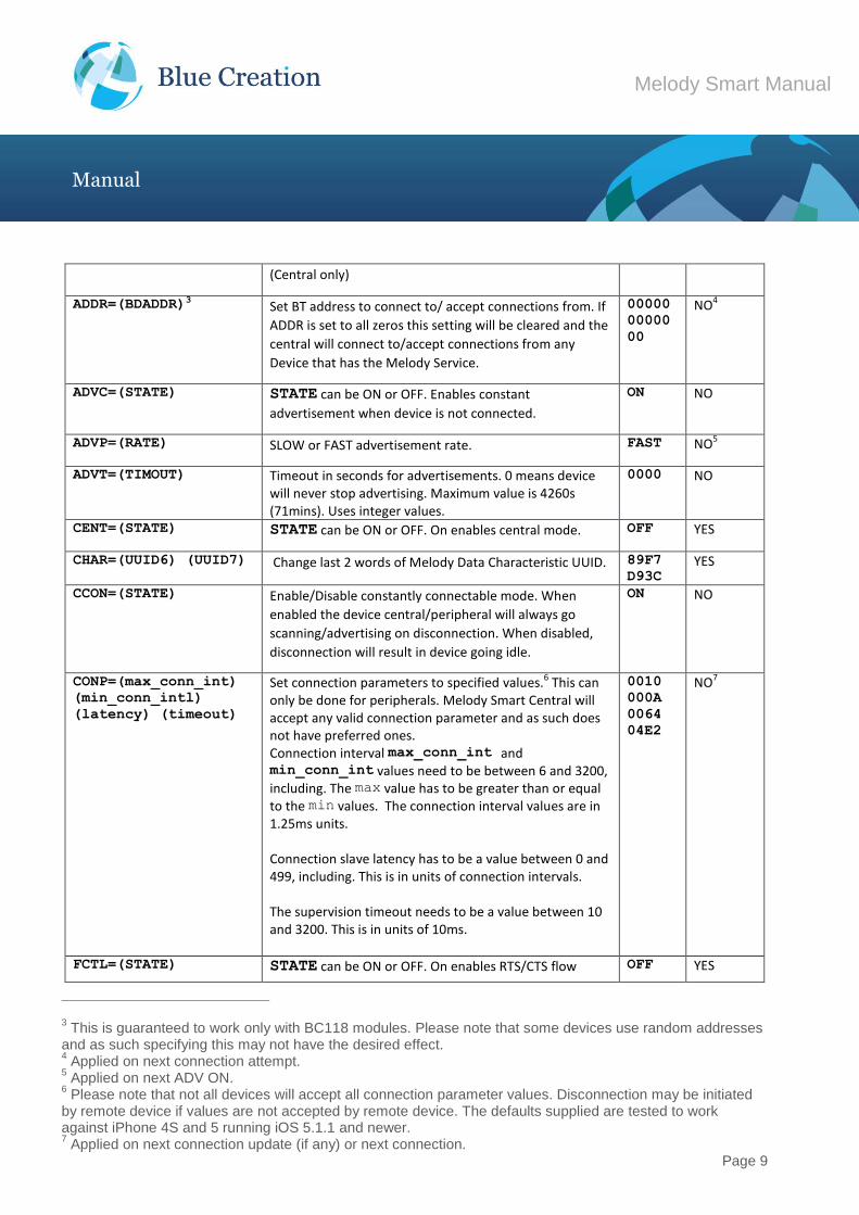
(Central only)
ADDR=(BDADDR)3 Set BT address to connect to/ accept connections from. If
ADDR is set to all zeros this setting will be cleared and the
central will connect to/accept connections from any
Device that has the Melody Service.
00000
00000
00
NO4
ADVC=(STATE) STATE can be ON or OFF. Enables constant
advertisement when device is not connected.
ON NO
ADVP=(RATE) SLOW or FAST advertisement rate. FAST NO5
ADVT=(TIMOUT) Timeout in seconds for advertisements. 0 means device will never stop advertising. Maximum value is 4260s (71mins). Uses integer values.
0000 NO
CENT=(STATE) STATE can be ON or OFF. On enables central mode. OFF YES
CHAR=(UUID6) (UUID7) Change last 2 words of Melody Data Characteristic UUID. 89F7
D93C YES
CCON=(STATE) Enable/Disable constantly connectable mode. When
enabled the device central/peripheral will always go
scanning/advertising on disconnection. When disabled,
disconnection will result in device going idle.
ON NO
CONP=(max_conn_int)
(min_conn_intl)
(latency) (timeout)
Set connection parameters to specified values.6 This can only be done for peripherals. Melody Smart Central will accept any valid connection parameter and as such does not have preferred ones. Connection interval max_conn_int and min_conn_int values need to be between 6 and 3200, including. The max value has to be greater than or equal to the min values. The connection interval values are in 1.25ms units. Connection slave latency has to be a value between 0 and 499, including. This is in units of connection intervals. The supervision timeout needs to be a value between 10 and 3200. This is in units of 10ms.
0010
000A
0064
04E2
NO7
FCTL=(STATE) STATE can be ON or OFF. On enables RTS/CTS flow OFF YES
3 This is guaranteed to work only with BC118 modules. Please note that some devices use random addresses
and as such specifying this may not have the desired effect. 4 Applied on next connection attempt.
5 Applied on next ADV ON.
6 Please note that not all devices will accept all connection parameter values. Disconnection may be initiated
by remote device if values are not accepted by remote device. The defaults supplied are tested to work against iPhone 4S and 5 running iOS 5.1.1 and newer. 7 Applied on next connection update (if any) or next connection.
Page 10
Melody Smart Manual
Manual
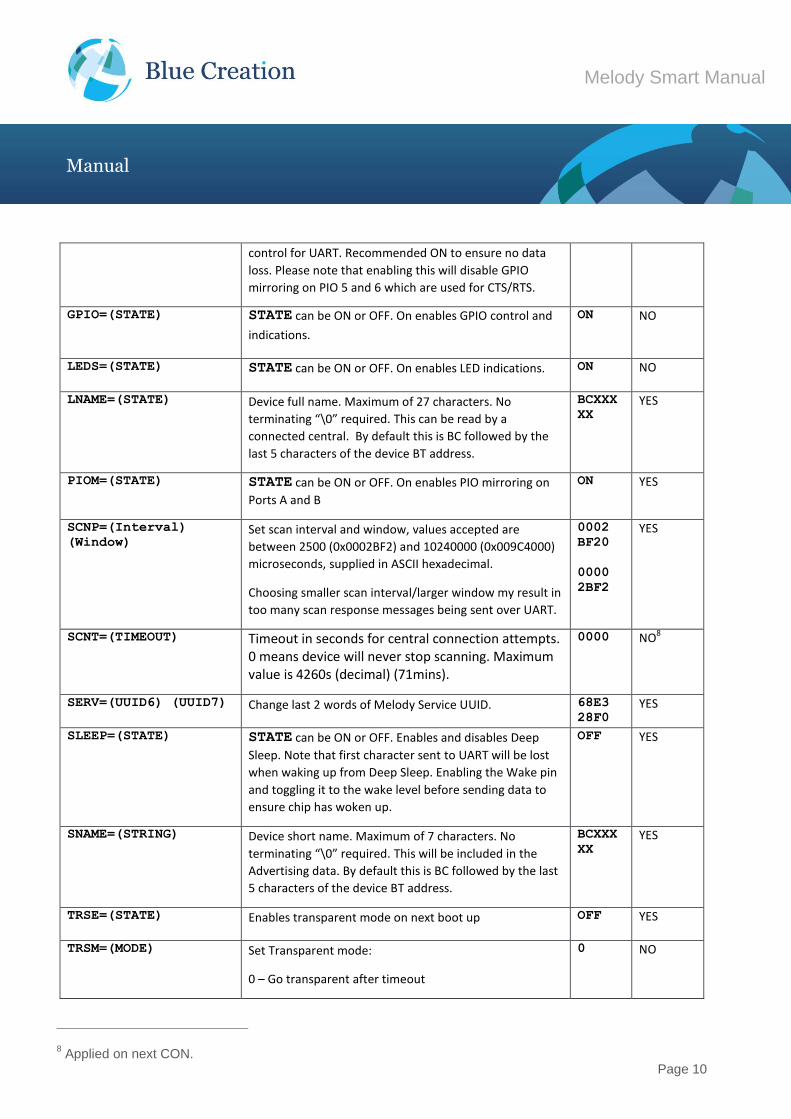
control for UART. Recommended ON to ensure no data
loss. Please note that enabling this will disable GPIO
mirroring on PIO 5 and 6 which are used for CTS/RTS.
GPIO=(STATE) STATE can be ON or OFF. On enables GPIO control and
indications.
ON NO
LEDS=(STATE) STATE can be ON or OFF. On enables LED indications. ON NO
LNAME=(STATE) Device full name. Maximum of 27 characters. No
terminating “\0” required. This can be read by a
connected central. By default this is BC followed by the
last 5 characters of the device BT address.
BCXXX
XX YES
PIOM=(STATE) STATE can be ON or OFF. On enables PIO mirroring on
Ports A and B
ON YES
SCNP=(Interval)
(Window) Set scan interval and window, values accepted are
between 2500 (0x0002BF2) and 10240000 (0x009C4000)
microseconds, supplied in ASCII hexadecimal.
Choosing smaller scan interval/larger window my result in
too many scan response messages being sent over UART.
0002
BF20
0000
2BF2
YES
SCNT=(TIMEOUT) Timeout in seconds for central connection attempts. 0 means device will never stop scanning. Maximum value is 4260s (decimal) (71mins).
0000 NO8
SERV=(UUID6) (UUID7) Change last 2 words of Melody Service UUID. 68E3
28F0 YES
SLEEP=(STATE) STATE can be ON or OFF. Enables and disables Deep
Sleep. Note that first character sent to UART will be lost
when waking up from Deep Sleep. Enabling the Wake pin
and toggling it to the wake level before sending data to
ensure chip has woken up.
OFF YES
SNAME=(STRING) Device short name. Maximum of 7 characters. No
terminating “\0” required. This will be included in the
Advertising data. By default this is BC followed by the last
5 characters of the device BT address.
BCXXX
XX YES
TRSE=(STATE) Enables transparent mode on next boot up OFF YES
TRSM=(MODE) Set Transparent mode:
0 – Go transparent after timeout
0 NO
8 Applied on next CON.
Page 11
Melody Smart Manual
Manual
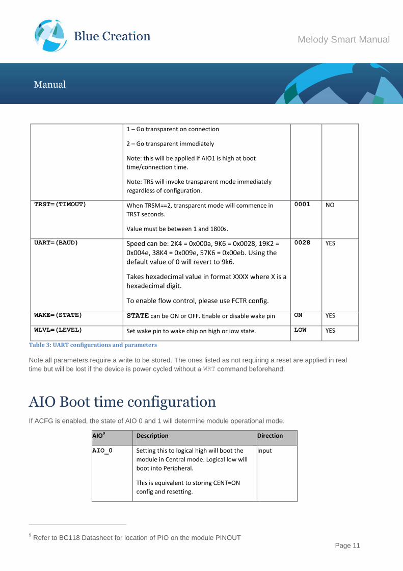
1 – Go transparent on connection
2 – Go transparent immediately
Note: this will be applied if AIO1 is high at boot
time/connection time.
Note: TRS will invoke transparent mode immediately
regardless of configuration.
TRST=(TIMOUT) When TRSM==2, transparent mode will commence in
TRST seconds.
Value must be between 1 and 1800s.
0001 NO
UART=(BAUD) Speed can be: 2K4 = 0x000a, 9K6 = 0x0028, 19K2 = 0x004e, 38K4 = 0x009e, 57K6 = 0x00eb. Using the default value of 0 will revert to 9k6.
Takes hexadecimal value in format XXXX where X is a hexadecimal digit.
To enable flow control, please use FCTR config.
0028 YES
WAKE=(STATE) STATE can be ON or OFF. Enable or disable wake pin ON YES
WLVL=(LEVEL) Set wake pin to wake chip on high or low state. LOW YES
Table 3: UART configurations and parameters
Note all parameters require a write to be stored. The ones listed as not requiring a reset are applied in real
time but will be lost if the device is power cycled without a WRT command beforehand.
AIO Boot time configuration If ACFG is enabled, the state of AIO 0 and 1 will determine module operational mode.
AIO9 Description Direction
AIO_0 Setting this to logical high will boot the
module in Central mode. Logical low will
boot into Peripheral.
This is equivalent to storing CENT=ON
config and resetting.
Input
9 Refer to BC118 Datasheet for location of PIO on the module PINOUT
Page 12
Melody Smart Manual
Manual
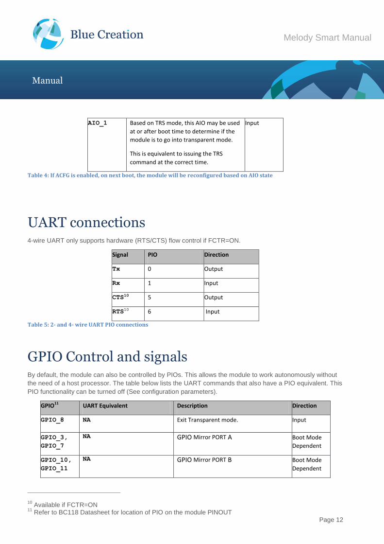
AIO_1 Based on TRS mode, this AIO may be used
at or after boot time to determine if the
module is to go into transparent mode.
This is equivalent to issuing the TRS
command at the correct time.
Input
Table 4: If ACFG is enabled, on next boot, the module will be reconfigured based on AIO state
UART connections 4-wire UART only supports hardware (RTS/CTS) flow control if FCTR=ON.
Signal PIO Direction
Tx 0 Output
Rx 1 Input
CTS10 5 Output
RTS10 6 Input
Table 5: 2- and 4- wire UART PIO connections
GPIO Control and signals By default, the module can also be controlled by PIOs. This allows the module to work autonomously without
the need of a host processor. The table below lists the UART commands that also have a PIO equivalent. This
PIO functionality can be turned off (See configuration parameters).
GPIO11 UART Equivalent Description Direction
GPIO_8 NA Exit Transparent mode. Input
GPIO_3,
GPIO_7
NA GPIO Mirror PORT A Boot Mode
Dependent
GPIO_10,
GPIO_11
NA GPIO Mirror PORT B Boot Mode
Dependent
10 Available if FCTR=ON
11 Refer to BC118 Datasheet for location of PIO on the module PINOUT
Page 13
Melody Smart Manual
Manual
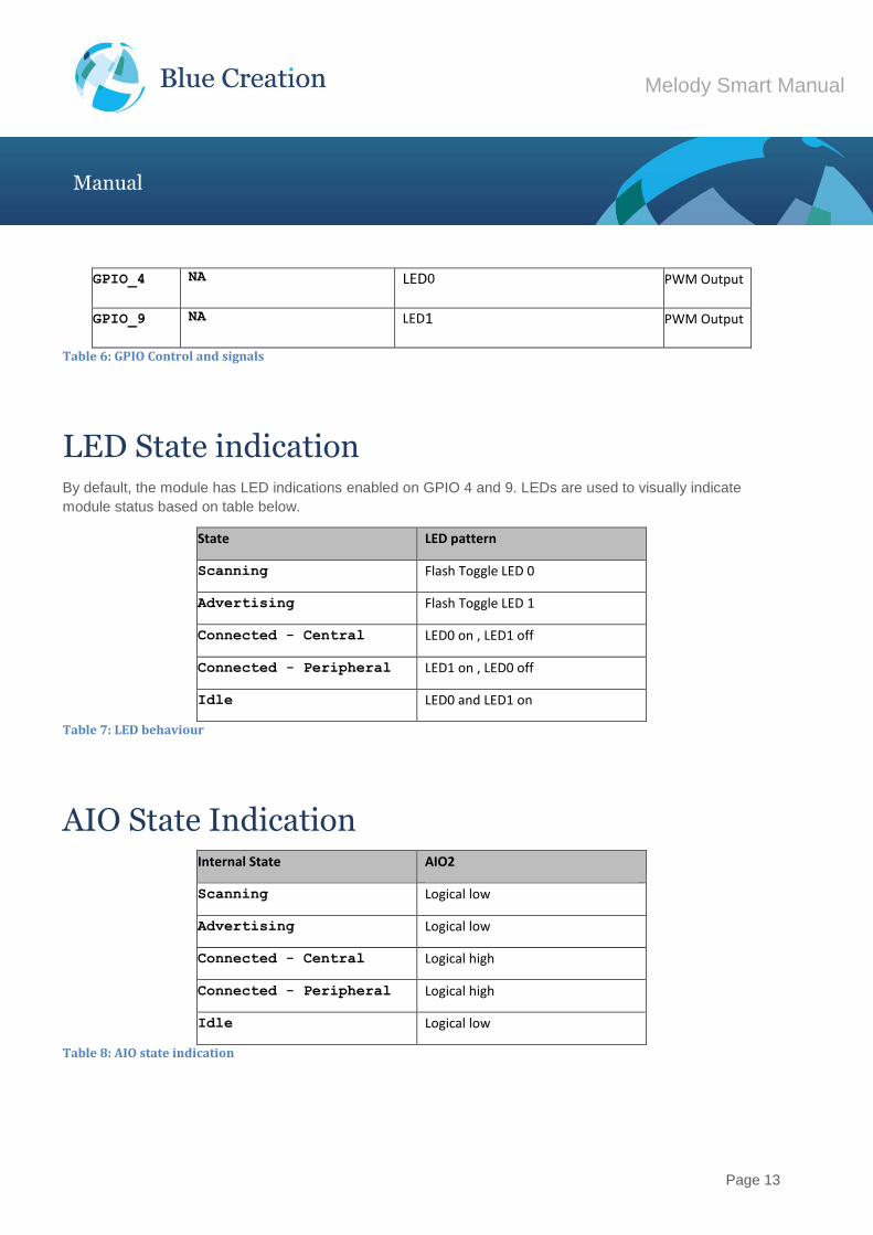
GPIO_4 NA LED0 PWM Output
GPIO_9 NA LED1 PWM Output
Table 6: GPIO Control and signals
LED State indication By default, the module has LED indications enabled on GPIO 4 and 9. LEDs are used to visually indicate
module status based on table below.
State LED pattern
Scanning Flash Toggle LED 0
Advertising Flash Toggle LED 1
Connected - Central LED0 on , LED1 off
Connected - Peripheral LED1 on , LED0 off
Idle LED0 and LED1 on
Table 7: LED behaviour
AIO State Indication Internal State AIO2
Scanning Logical low
Advertising Logical low
Connected - Central Logical high
Connected - Peripheral Logical high
Idle Logical low
Table 8: AIO state indication
Page 14
Melody Smart Manual
Manual
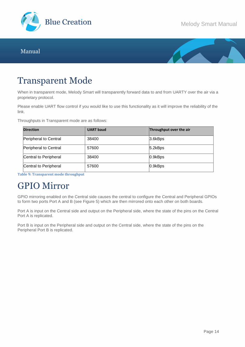
Transparent Mode When in transparent mode, Melody Smart will transparently forward data to and from UARTY over the air via a
proprietary protocol.
Please enable UART flow control if you would like to use this functionality as it will improve the reliability of the
link.
Throughputs in Transparent mode are as follows:
Direction UART baud Throughput over the air
Peripheral to Central 38400 3.6kBps
Peripheral to Central 57600 5.2kBps
Central to Peripheral 38400 0.9kBps
Central to Peripheral 57600 0.9kBps
Table 9: Transparent mode throughput
GPIO Mirror GPIO mirroring enabled on the Central side causes the central to configure the Central and Peripheral GPIOs to form two ports Port A and B (see Figure 5) which are then mirrored onto each other on both boards. Port A is input on the Central side and output on the Peripheral side, where the state of the pins on the Central Port A is replicated. Port B is input on the Peripheral side and output on the Central side, where the state of the pins on the Peripheral Port B is replicated.
Page 15
Melody Smart Manual
Manual
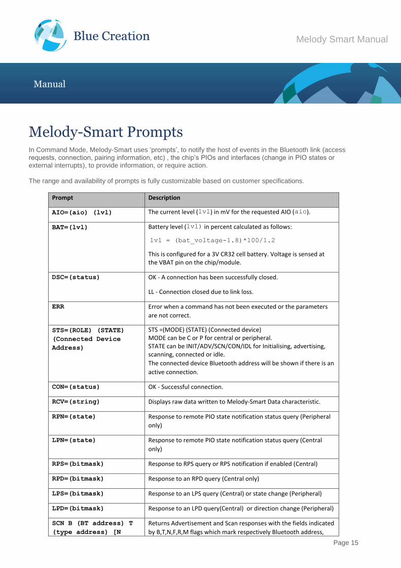
Melody-Smart Prompts In Command Mode, Melody-Smart uses ‘prompts’, to notify the host of events in the Bluetooth link (access requests, connection, pairing information, etc) , the chip’s PIOs and interfaces (change in PIO states or external interrupts), to provide information, or require action. The range and availability of prompts is fully customizable based on customer specifications.
Prompt Description
AIO=(aio) (lvl) The current level (lvl) in mV for the requested AIO (aio).
BAT=(lvl) Battery level (lvl) in percent calculated as follows:
lvl = (bat_voltage-1.8)*100/1.2
This is configured for a 3V CR32 cell battery. Voltage is sensed at the VBAT pin on the chip/module.
DSC=(status) OK - A connection has been successfully closed.
LL - Connection closed due to link loss.
ERR Error when a command has not been executed or the parameters
are not correct.
STS=(ROLE) (STATE)
(Connected Device
Address)
STS =(MODE) (STATE) (Connected device) MODE can be C or P for central or peripheral. STATE can be INIT/ADV/SCN/CON/IDL for Initialising, advertising, scanning, connected or idle.
The connected device Bluetooth address will be shown if there is an
active connection.
CON=(status) OK - Successful connection.
RCV=(string) Displays raw data written to Melody-Smart Data characteristic.
RPN=(state) Response to remote PIO state notification status query (Peripheral
only)
LPN=(state) Response to remote PIO state notification status query (Central
only)
RPS=(bitmask) Response to RPS query or RPS notification if enabled (Central)
RPD=(bitmask) Response to an RPD query (Central only)
LPS=(bitmask) Response to an LPS query (Central) or state change (Peripheral)
LPD=(bitmask) Response to an LPD query(Central) or direction change (Peripheral)
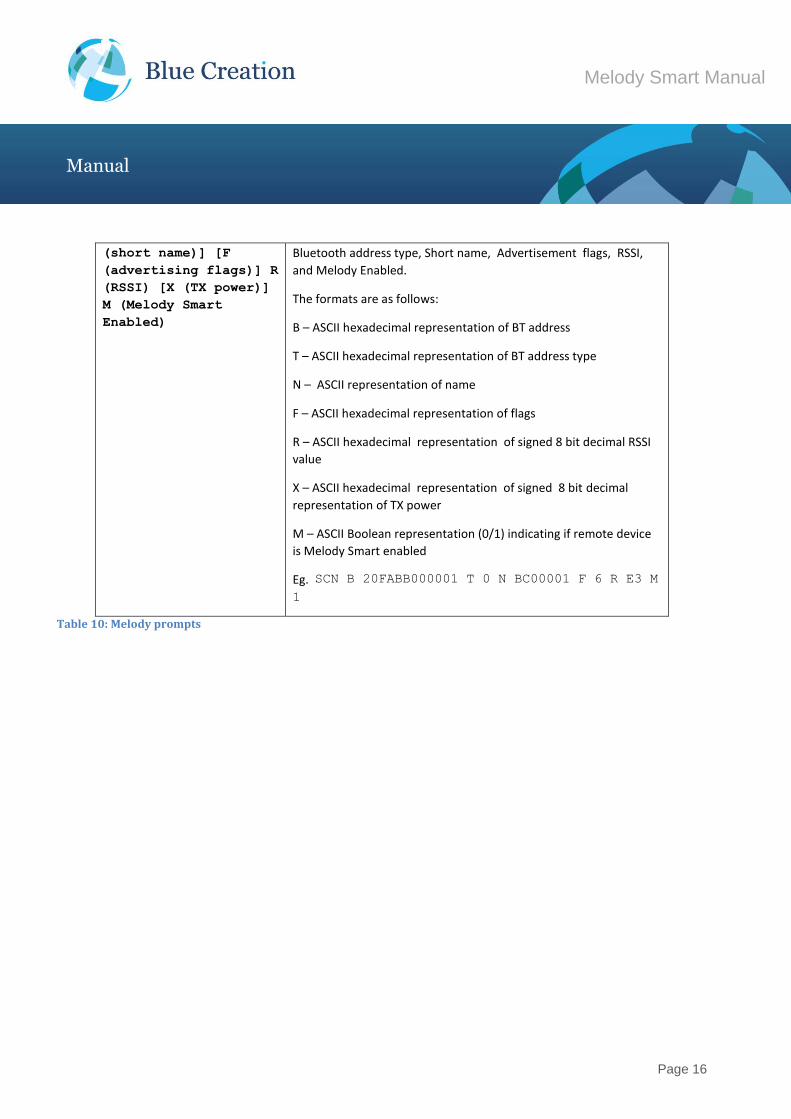
SCN B (BT address) T
(type address) [N
Returns Advertisement and Scan responses with the fields indicated
by B,T,N,F,R,M flags which mark respectively Bluetooth address,
Page 16
Melody Smart Manual
Manual
(short name)] [F
(advertising flags)] R
(RSSI) [X (TX power)]
M (Melody Smart
Enabled)
Bluetooth address type, Short name, Advertisement flags, RSSI,
and Melody Enabled.
The formats are as follows:
B – ASCII hexadecimal representation of BT address
T – ASCII hexadecimal representation of BT address type
N – ASCII representation of name
F – ASCII hexadecimal representation of flags
R – ASCII hexadecimal representation of signed 8 bit decimal RSSI
value
X – ASCII hexadecimal representation of signed 8 bit decimal
representation of TX power
M – ASCII Boolean representation (0/1) indicating if remote device
is Melody Smart enabled
Eg. SCN B 20FABB000001 T 0 N BC00001 F 6 R E3 M
1
Table 10: Melody prompts
Page 17
Melody Smart Manual
Manual
Over The Air Updates (OTAU)
Starting from version 2.5.0, Melody Smart supports Over The Air Updates (OTAU). This allows for Melody
Smart to be updated via a BLE enabled mobile phone.
BlueCreation constantly improves on Melody Smart and this is the easiest way to get the latest features and
bugfixes. Performing an OTAU will preserve your stored settings, unless otherwise stated in the update
release notes.
Before you start:
1) Ensure your Melody Smart device is not battery powered or if battery powered fully charged!
2) Ensure your phone has above 60% battery power or is being charged.
3) Ensure you have access to the internet and that if using mobile internet you are OK with the costs of
downloading the update image (approx 300kB) and if you do not have it pre-installed the Melody Smart App.
We suggest you use Wi-Fi.
In order to perform OTAU, please follow these steps:
1) Download the Melody Smart app from iTunes or Play Store.
2) Set your Melody Smart to peripheral mode (SET CENT=OFF), store (WRT) and reset (RST)
3) Open the Melody Smart application, choose your device and connect.
4) Once the application is connected choose "Firmware Upgrade".
5) Select the firmware you would like to upgrade to. We suggest always using the latest, unless you have
been instructed by BlueCreation to downgrade.
6) The upgrade screen will show you your current firmware version and upgrade version.
7) Select “Update Melody Smart" - this will start the process.
8) You will be asked to pair your device, if you have not done so already. Accept.
9) The update image file will download from the BlueCreation website and the update process will begin.
10) The status bar will show how far along the update process you are.
11) Do not switch off either device, walk away with your phone or disable Bluetooth as this will cause the
update process to fail. This can be recovered from; however, it is an unnecessary complication.
12) Once the device completes the update you will be notified of a disconnection. The device will restart and
load the new firmware.
13) Go back using the back button to the device screen and reconnect to your device as needed.
Page 18
Melody Smart Manual
Manual
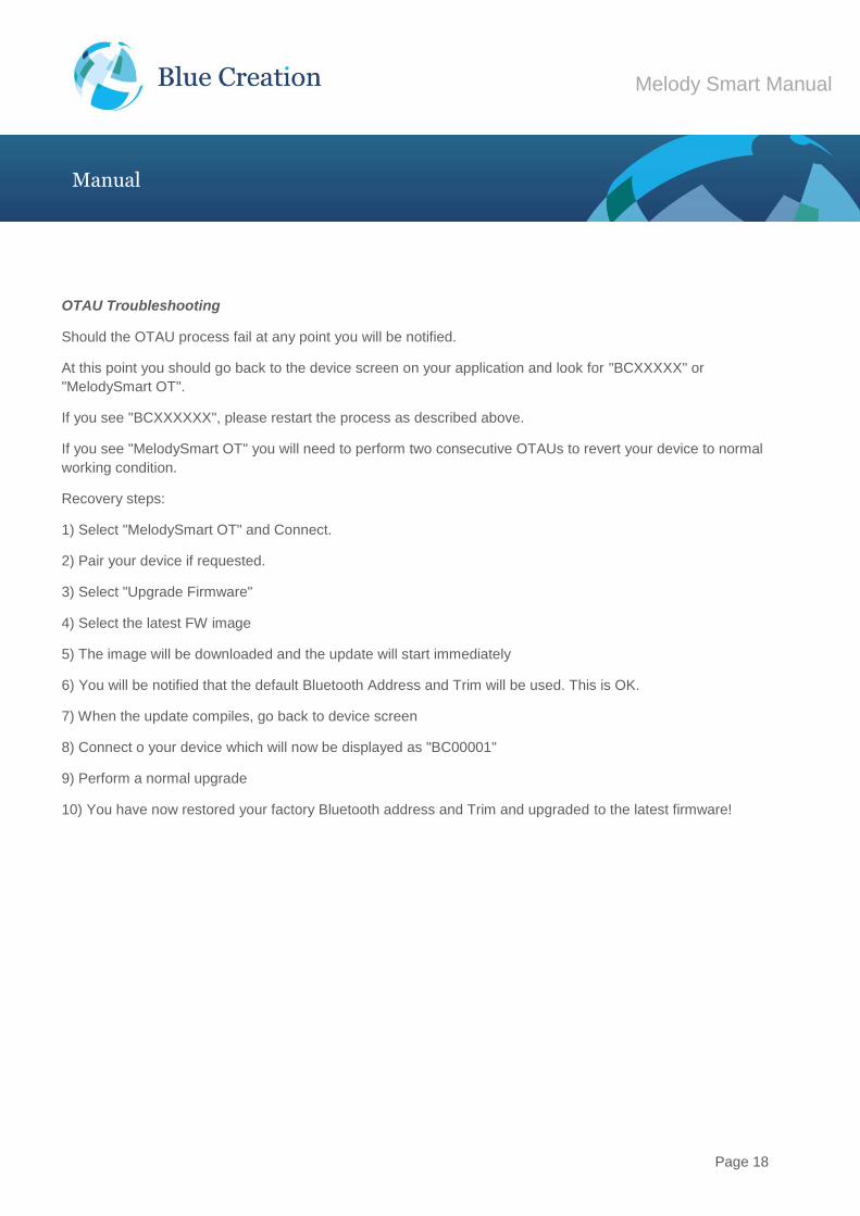
OTAU Troubleshooting
Should the OTAU process fail at any point you will be notified.
At this point you should go back to the device screen on your application and look for "BCXXXXX" or
"MelodySmart OT".
If you see "BCXXXXXX", please restart the process as described above.
If you see "MelodySmart OT" you will need to perform two consecutive OTAUs to revert your device to normal
working condition.
Recovery steps:
1) Select "MelodySmart OT" and Connect.
2) Pair your device if requested.
3) Select "Upgrade Firmware"
4) Select the latest FW image
5) The image will be downloaded and the update will start immediately
6) You will be notified that the default Bluetooth Address and Trim will be used. This is OK.
7) When the update compiles, go back to device screen
8) Connect o your device which will now be displayed as "BC00001"
9) Perform a normal upgrade
10) You have now restored your factory Bluetooth address and Trim and upgraded to the latest firmware!
Page 19
Melody Smart Manual
Manual
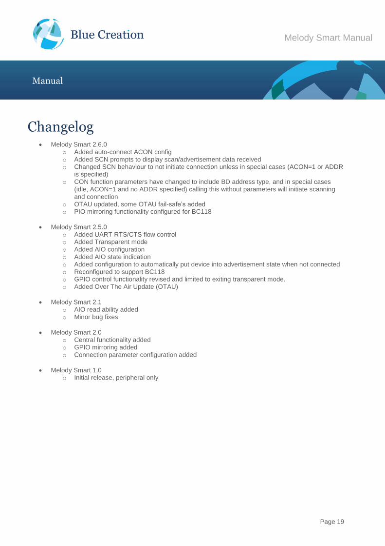
Changelog Melody Smart 2.6.0
o Added auto-connect ACON config o Added SCN prompts to display scan/advertisement data received o Changed SCN behaviour to not initiate connection unless in special cases (ACON=1 or ADDR
is specified) o CON function parameters have changed to include BD address type, and in special cases
(idle, ACON=1 and no ADDR specified) calling this without parameters will initiate scanning and connection
o OTAU updated, some OTAU fail-safe’s added o PIO mirroring functionality configured for BC118
Melody Smart 2.5.0 o Added UART RTS/CTS flow control o Added Transparent mode o Added AIO configuration o Added AIO state indication o Added configuration to automatically put device into advertisement state when not connected o Reconfigured to support BC118 o GPIO control functionality revised and limited to exiting transparent mode. o Added Over The Air Update (OTAU)
Melody Smart 2.1 o AIO read ability added o Minor bug fixes
Melody Smart 2.0 o Central functionality added o GPIO mirroring added o Connection parameter configuration added
Melody Smart 1.0 o Initial release, peripheral only