Embed Size (px)
Citation preview
MELSEC-Q/L Ethernet Interface ModuleUser's Manual (Application)
-QJ71E71-100-QJ71E71-B5-QJ71E71-B2-LJ71E71-100


SAFETY PRECAUTIONS(Read these precautions before using this product.)
Before using this product, please read this manual and the relevant manuals carefully and pay full attention
to safety to handle the product correctly.
The precautions given in this manual are concerned with this product only. For the safety precautions of the
programmable controller system, refer to the user's manual for the CPU module used.
In this manual, the safety precautions are classified into two levels: " WARNING" and " CAUTION".
Under some circumstances, failure to observe the precautions given under " CAUTION" may lead to
serious consequences.
Observe the precautions of both levels because they are important for personal and system safety.
Make sure that the end users read this manual and then keep the manual in a safe place for future
reference.
WARNING
CAUTION
Indicates that incorrect handling may cause hazardous conditions,resulting in death or severe injury.
Indicates that incorrect handling may cause hazardous conditions, resulting in minor or moderate injury or property damage.
1
Precautions for using the MELSEC-Q series Ethernet interface module
[Design Precautions]
[Design Precautions]
WARNING● For the operating status of each station after a communication failure, refer to relevant manuals for the
network.
Failure to do so may result in an accident due to an incorrect output or malfunction.
● To prevent the malfunction of the programmable controller system due to harmful e-mails, take
preventive measures (such as antivirus measures) so that the mail server for this module does not
receive harmful e-mails.
● To maintain the safety of the programmable controller system against unauthorized access from
external devices via the Internet, take appropriate measures.
● When connecting a peripheral with the CPU module or connecting a personal computer with an
intelligent function module to modify data of a running programmable controller, configure an interlock
circuit in the sequence program to ensure that the entire system will always operate safely.
For other forms of control (such as program modification or operating status change) of a running
programmable controller, read the relevant manuals carefully and ensure that the operation is safe
before proceeding.
Especially, when a remote programmable controller is controlled by an external device, immediate
action cannot be taken if a problem occurs in the programmable controller due to a communication
failure.
To prevent this, configure an interlock circuit in the sequence program, and determine corrective
actions to be taken between the external device and CPU module in case of a communication failure.
● Do not write any data to the "system area" of the buffer memory in the intelligent function module.
Also, do not use any "use prohibited" signals as an output signal from the programmable controller
CPU to the intelligent function module.
Doing so may cause malfunction of the programmable controller system.
CAUTION● Do not install the control lines or communication cables together with the main circuit lines or power
cables.
Keep a distance of 100mm or more between them.
Failure to do so may result in malfunction due to noise.
● When changing the operating status of the programmable controller CPU (such as remote
RUN/STOP) from the external device, select "Always wait for OPEN (Communication possible at
STOP time)" for the "Initial timing" setting in the network parameter.
The communication line will be closed when "Do not wait for OPEN (Communications impossible at
STOP time)" is selected and the remote STOP is executed from the external device.
Consequently, the programmable controller CPU cannot reopen the communication line, and the
external device cannot execute the remote RUN.
2
[Installation Precautions]
CAUTION● Use the programmable controller in an environment that meets the general specifications in the user's
manual for the CPU module used.
Failure to do so may result in electric shock, fire, malfunction, or damage to or deterioration of the
product.
● To mount the module, while pressing the module mounting lever located in the lower part of the
module, fully insert the module fixing projection(s) into the hole(s) in the base unit and press the
module until it snaps into place.
Incorrect interconnection may cause malfunction, failure, or drop of the module.
When using the programmable controller in an environment of frequent vibrations, fix the module with
a screw.
● Tighten the screws within the specified torque range.
Undertightening can cause drop of the screw, short circuit, or malfunction.
Overtightening can damage the screw and/or module, resulting in drop, short circuit, or malfunction.
● Shut off the external power supply (all phases) used in the system before mounting or removing a
module.
Failure to do so may result in damage to the product.
● Do not directly touch any conductive parts and electronic components of the module.
Doing so can cause malfunction or failure of the module.
3
[Wiring Precautions]
CAUTION● Connectors for external connection must be crimped or pressed with the tool specified by the
manufacturer, or must be correctly soldered.
Incomplete connections may cause short circuit, fire, or malfunction.
● Shut off the external power supply for the system in all phases before connecting the AUI cable.
● When connecting a cable with connector to the module, connect the connector part to the module
securely.
● Make sure to place the communication and power cables to be connected to the module in a duct or
fasten them using a clamp.
If not, dangling cable may swing or inadvertently be pulled, resulting in damage to the module or
cables or malfunction due to poor contact.
● Tighten the terminal screws using the specified torque.
Undertightening can cause short circuit or malfunction.
Overtightening can damage the screw and/or module, resulting in drop, short circuit, or malfunction.
● When disconnecting the cable from the module, do not pull the cable by the cable part.
For the cable with connector, hold the connector part of the cable.
For the cable connected to the terminal block, loosen the terminal screw.
Pulling the cable connected to the module may result in malfunction or damage to the module or
cable.
● Prevent foreign matter such as dust or wire chips from entering the module.
Such foreign matter can cause a fire, failure, or malfunction.
● A protective film is attached to the top of the module to prevent foreign matter, such as wire chips,
from entering the module during wiring.
Do not remove the film during wiring.
Remove it for heat dissipation before system operation.
● Correctly solder coaxial cable connectors. Incomplete soldering may result in malfunction.
4
[Startup and Maintenance Precautions]
[Operating Precautions]
[Disposal Precautions]
CAUTION● Do not disassemble or modify the module. Doing so may cause failure, malfunction, injury, or a fire.
● Shut off the external power supply (all phases) used in the system before mounting or removing a
module.
Failure to do so may cause the module to fail or malfunction.
● After the first use of the product, do not mount/remove the module to/from the base unit more than 50
times (in accordance with IEC 61131-2).
Exceeding the limit may cause malfunction.
● Do not touch any terminal while power is on.
Failure to do so may cause malfunction.
● Shut off the external power supply (all phases) used in the system before cleaning the module or
retightening the terminal screws or module fixing screws.
Failure to do so may cause the module to fail or malfunction.
Undertightening can cause drop of the screw, short circuit, or malfunction.
Overtightening can damage the screw and/or module, resulting in drop, short circuit, or malfunction.
● Before handling the module, touch a conducting object such as a grounded metal to discharge the
static electricity from the human body.
Failure to do so may cause the module to fail or malfunction.
CAUTION● When changing data and operating status, and modifying program of the running programmable
controller from a personal computer connected to an intelligent function module, read relevant
manuals carefully and ensure the safety before operation.
Incorrect change or modification may cause system malfunction, damage to the machines, or
accidents.
CAUTION● When disposing of this product, treat it as industrial waste.
5
Precautions for using the MELSEC-L series Ethernet interface module
[Design Precautions]
[Design Precautions]
WARNING● For the operating status of each station after a communication failure, refer to relevant manuals for the
network. Failure to do so may result in an accident due to an incorrect output or malfunction.
● To prevent the malfunction of the programmable controller system due to harmful e-mails, take
preventive measures (such as antivirus measures) so that the mail server for this module does not
receive harmful e-mails.
● To maintain the safety of the programmable controller system against unauthorized access from
external devices via the Internet, take appropriate measures.
● When connecting a peripheral with the CPU module or connecting an external device, such as a
personal computer, with an intelligent function module to modify data of a running programmable
controller, configure an interlock circuit in the program to ensure that the entire system will always
operate safely. For other forms of control (such as program modification or operating status change)
of a running programmable controller, read the relevant manuals carefully and ensure that the
operation is safe before proceeding. Especially, when a remote programmable controller is controlled
by an external device, immediate action cannot be taken if a problem occurs in the programmable
controller due to a communication failure. To prevent this, configure an interlock circuit in the program,
and determine corrective actions to be taken between the external device and CPU module in case of
a communication failure.
● Do not write any data to the "system area" of the buffer memory in the intelligent function module.
Also, do not use any "use prohibited" signals as an output signal from the CPU module to the
intelligent function module. Doing so may cause malfunction of the programmable controller system.
CAUTION● Do not install the control lines or communication cables together with the main circuit lines or power
cables. Keep a distance of 100mm or more between them. Failure to do so may result in malfunction
due to noise.
● When changing the operating status of the CPU module (such as remote RUN/STOP) from the
external device, select "Always wait for OPEN (Communication possible at STOP time)" for the "Initial
timing" setting in the network parameter. The communication line will be closed when "Do not wait for
OPEN (Communications impossible at STOP time)" is selected and the remote STOP is executed
from the external device. Consequently, the CPU module cannot reopen the communication line, and
the external device cannot execute the remote RUN.
6
[Installation Precautions]
[Wiring Precautions]
CAUTION● Use the programmable controller in an environment that meets the general specifications in the Safety
Guidelines included with the MELSEC-L series CPU module.
Failure to do so may result in electric shock, fire, malfunction, or damage to or deterioration of the
product.
● To interconnect modules, engage the respective connectors and securely lock the module joint levers
until they click. Incorrect interconnection may cause malfunction, failure, or drop of the module.
● Shut off the external power supply (all phases) used in the system before mounting or removing a
module. Failure to do so may result in damage to the product.
● Do not directly touch any conductive parts and electronic components of the module. Doing so can
cause malfunction or failure of the module.
CAUTION● When connecting a cable with connector to the module, connect the connector part to the module
securely.
● Make sure to place the communication and power cables to be connected to the module in a duct or
fasten them using a clamp. If not, dangling cable may swing or inadvertently be pulled, resulting in
damage to the module or cables or malfunction due to poor contact.
● Prevent foreign matter such as dust or wire chips from entering the module. Such foreign matter can
cause a fire, failure, or malfunction.
● A protective film is attached to the top of the module to prevent foreign matter, such as wire chips,
from entering the module during wiring. Do not remove the film during wiring. Remove it for heat
dissipation before system operation.
7
[Startup and Maintenance Precautions]
[Startup and Maintenance Precautions]
[Operating Precautions]
[Disposal Precautions]
WARNING● Shut off the external power supply (all phases) used in the system before cleaning the module. Failure
to do so may result in electric shock.
CAUTION● Do not disassemble or modify the module. Doing so may cause failure, malfunction, injury, or a fire.
● Shut off the external power supply (all phases) used in the system before mounting or removing a
module. Failure to do so may cause the module to fail or malfunction.
● After the first use of the product (module and display unit), the number of connections/disconnections
is limited to 50 times (in accordance with IEC 61131-2). Exceeding the limit may cause malfunction.
● Before handling the module, touch a conducting object such as a grounded metal to discharge the
static electricity from the human body. Failure to do so may cause the module to fail or malfunction.
CAUTION● When changing data and operating status, and modifying program of the running programmable
controller from a personal computer connected to an intelligent function module, read relevant
manuals carefully and ensure the safety before operation. Incorrect change or modification may
cause system malfunction, damage to the machines, or accidents.
CAUTION● When disposing of this product, treat it as industrial waste.
8

CONDITIONS OF USE FOR THE PRODUCT
INTRODUCTION
Thank you for purchasing the Mitsubishi MELSEC-Q or -L series programmable controllers.
This manual describes the functions and programming of the Ethernet interface module for Ethernet communications.
Before using this product, please read this manual and the relevant manuals carefully and develop familiarity with the
functions and performance of the MELSEC-Q or -L series programmable controller to handle the product correctly.
When applying the program examples introduced in this manual to an actual system, ensure the applicability and
confirm that it will not cause system control problems.
Please make sure that the end users read this manual.
Remark
Unless otherwise specified, this manual describes the program examples in which the I/O numbers of X/Y00 to X/Y1F are assigned for an Ethernet interface module.For I/O number assignment, refer to the User's Manual (Function Explanation, Program Fundamentals) for the CPU module used.
(1) Mitsubishi programmable controller ("the PRODUCT") shall be used in conditions;i) where any problem, fault or failure occurring in the PRODUCT, if any, shall not lead to any major or serious accident; and ii) where the backup and fail-safe function are systematically or automatically provided outside of the PRODUCT for the case of any problem, fault or failure occurring in the PRODUCT.
(2) The PRODUCT has been designed and manufactured for the purpose of being used in general industries.MITSUBISHI SHALL HAVE NO RESPONSIBILITY OR LIABILITY (INCLUDING, BUT NOT LIMITED TO ANY AND ALL RESPONSIBILITY OR LIABILITY BASED ON CONTRACT, WARRANTY, TORT, PRODUCT LIABILITY) FOR ANY INJURY OR DEATH TO PERSONS OR LOSS OR DAMAGE TO PROPERTY CAUSED BY the PRODUCT THAT ARE OPERATED OR USED IN APPLICATION NOT INTENDED OR EXCLUDED BY INSTRUCTIONS, PRECAUTIONS, OR WARNING CONTAINED IN MITSUBISHI'S USER, INSTRUCTION AND/OR SAFETY MANUALS, TECHNICAL BULLETINS AND GUIDELINES FOR the PRODUCT. ("Prohibited Application")Prohibited Applications include, but not limited to, the use of the PRODUCT in;• Nuclear Power Plants and any other power plants operated by Power companies, and/or any other cases in which the
public could be affected if any problem or fault occurs in the PRODUCT.• Railway companies or Public service purposes, and/or any other cases in which establishment of a special quality
assurance system is required by the Purchaser or End User.• Aircraft or Aerospace, Medical applications, Train equipment, transport equipment such as Elevator and Escalator,
Incineration and Fuel devices, Vehicles, Manned transportation, Equipment for Recreation and Amusement, and Safety devices, handling of Nuclear or Hazardous Materials or Chemicals, Mining and Drilling, and/or other applications where there is a significant risk of injury to the public or property.
Notwithstanding the above, restrictions Mitsubishi may in its sole discretion, authorize use of the PRODUCT in one or more of the Prohibited Applications, provided that the usage of the PRODUCT is limited only for the specific applications agreed to by Mitsubishi and provided further that no special quality assurance or fail-safe, redundant or other safety features which exceed the general specifications of the PRODUCTs are required. For details, please contact the Mitsubishi representative in your region.
9
RELEVANT MANUALS
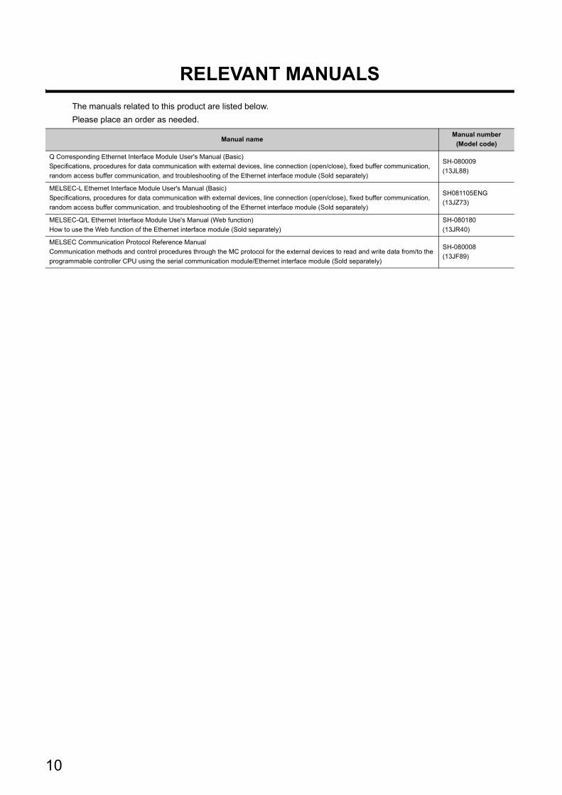
The manuals related to this product are listed below.
Please place an order as needed.
Manual nameManual number
(Model code)
Q Corresponding Ethernet Interface Module User's Manual (Basic)
Specifications, procedures for data communication with external devices, line connection (open/close), fixed buffer communication,
random access buffer communication, and troubleshooting of the Ethernet interface module (Sold separately)
SH-080009
(13JL88)
MELSEC-L Ethernet Interface Module User's Manual (Basic)
Specifications, procedures for data communication with external devices, line connection (open/close), fixed buffer communication,
random access buffer communication, and troubleshooting of the Ethernet interface module (Sold separately)
SH081105ENG
(13JZ73)
MELSEC-Q/L Ethernet Interface Module Use's Manual (Web function)
How to use the Web function of the Ethernet interface module (Sold separately)
SH-080180
(13JR40)
MELSEC Communication Protocol Reference Manual
Communication methods and control procedures through the MC protocol for the external devices to read and write data from/to the
programmable controller CPU using the serial communication module/Ethernet interface module (Sold separately)
SH-080008
(13JF89)
10

Memo
11
CONTENTS
12
CONTENTS
SAFETY PRECAUTIONS . . . . . . . . . . . . . . . . . . . . . . . . . . . . . . . . . . . . . . . . . . . . . . . . . . . . . . . . . . . . . 1CONDITIONS OF USE FOR THE PRODUCT . . . . . . . . . . . . . . . . . . . . . . . . . . . . . . . . . . . . . . . . . . . . . 9
INTRODUCTION . . . . . . . . . . . . . . . . . . . . . . . . . . . . . . . . . . . . . . . . . . . . . . . . . . . . . . . . . . . . . . . . . . . . 9RELEVANT MANUALS . . . . . . . . . . . . . . . . . . . . . . . . . . . . . . . . . . . . . . . . . . . . . . . . . . . . . . . . . . . . . . 10MANUAL'S USE AND STRUCTURE . . . . . . . . . . . . . . . . . . . . . . . . . . . . . . . . . . . . . . . . . . . . . . . . . . . 16TERMS . . . . . . . . . . . . . . . . . . . . . . . . . . . . . . . . . . . . . . . . . . . . . . . . . . . . . . . . . . . . . . . . . . . . . . . . . . 19
CHAPTER 1 OVERVIEW 21
1.1 Overview. . . . . . . . . . . . . . . . . . . . . . . . . . . . . . . . . . . . . . . . . . . . . . . . . . . . . . . . . . . . . . . . . . 21
1.2 Additional Functions in Function Version B or Later . . . . . . . . . . . . . . . . . . . . . . . . . . . . . . . . . 24
CHAPTER 2 USING THE E-MAIL FUNCTION 25
2.1 E-mail Function. . . . . . . . . . . . . . . . . . . . . . . . . . . . . . . . . . . . . . . . . . . . . . . . . . . . . . . . . . . . . 25
2.1.1 Sending/receiving e-mail by the programmable controller CPU . . . . . . . . . . . . . . . . . . . . . . .25
2.1.2 Sending e-mail using the programmable controller CPU monitor function . . . . . . . . . . . . . . .27
2.2 Configuration and Environment of the Applicable System . . . . . . . . . . . . . . . . . . . . . . . . . . . . 29
2.3 Precautions for Using the E-mail Function . . . . . . . . . . . . . . . . . . . . . . . . . . . . . . . . . . . . . . . . 30
2.4 E-mail Specifications. . . . . . . . . . . . . . . . . . . . . . . . . . . . . . . . . . . . . . . . . . . . . . . . . . . . . . . . . 32
2.5 Processing Procedure of the E-mail Function . . . . . . . . . . . . . . . . . . . . . . . . . . . . . . . . . . . . . 33
2.6 E-mail Setting Using a Programming Tool . . . . . . . . . . . . . . . . . . . . . . . . . . . . . . . . . . . . . . . . 34
2.7 Sending/Receiving E-mail (Attached Files) by the Programmable Controller CPU . . . . . . . . . 38
2.7.1 When sending data as an attached file . . . . . . . . . . . . . . . . . . . . . . . . . . . . . . . . . . . . . . . . . .38
2.7.2 When receiving data in the attached file . . . . . . . . . . . . . . . . . . . . . . . . . . . . . . . . . . . . . . . . .43
2.7.3 Contents of the attached files. . . . . . . . . . . . . . . . . . . . . . . . . . . . . . . . . . . . . . . . . . . . . . . . . .48
2.8 Sending E-mail (Main Text) by the Programmable Controller CPU . . . . . . . . . . . . . . . . . . . . . 50
2.8.1 When sending data as main text of e-mail . . . . . . . . . . . . . . . . . . . . . . . . . . . . . . . . . . . . . . . .50
2.9 Sending E-mails Using the Programmable Controller CPU Monitoring Function . . . . . . . . . . . 54
2.9.1 News setting. . . . . . . . . . . . . . . . . . . . . . . . . . . . . . . . . . . . . . . . . . . . . . . . . . . . . . . . . . . . . . .54
2.9.2 Receiving a news e-mail . . . . . . . . . . . . . . . . . . . . . . . . . . . . . . . . . . . . . . . . . . . . . . . . . . . . .58
CHAPTER 3 COMMUNICATIONS VIA OTHER NETWORKS 62
3.1 CC-Link IE Controller Network, CC-Link IE Field Network, MELSECNET/H,
MELSECNET/10 Relay Communication Function . . . . . . . . . . . . . . . . . . . . . . . . . . . . . . . . . . 62
3.2 Range of Accessible Other Station's Programmable Controllers and Accessible Stations. . . . 63
3.2.1 Accessible range and stations . . . . . . . . . . . . . . . . . . . . . . . . . . . . . . . . . . . . . . . . . . . . . . . . .63
3.3 Settings for Accessing Other Stations . . . . . . . . . . . . . . . . . . . . . . . . . . . . . . . . . . . . . . . . . . . 66
3.3.1 Setting the Station No. <-> IP information . . . . . . . . . . . . . . . . . . . . . . . . . . . . . . . . . . . . . . . .67
3.3.2 Convert format between the Network No./station number and IP address/port number . . . . .70
3.3.3 Routing parameter settings . . . . . . . . . . . . . . . . . . . . . . . . . . . . . . . . . . . . . . . . . . . . . . . . . . .76
3.4 Procedure for Accessing Other Stations. . . . . . . . . . . . . . . . . . . . . . . . . . . . . . . . . . . . . . . . . . 82
3.5 Precautions for Accessing Other Stations . . . . . . . . . . . . . . . . . . . . . . . . . . . . . . . . . . . . . . . . 83
CHAPTER 4 WHEN THE Q/LCPU ACCESSES THE PROGRAMMABLE CONTROLLER OF ANOTHER STATION USING THE DATA LINK INSTRUCTION 84
4.1 Access to Other Stations with the Data Link Instruction . . . . . . . . . . . . . . . . . . . . . . . . . . . . . . 84
4.2 Precautions for Accessing Other Stations . . . . . . . . . . . . . . . . . . . . . . . . . . . . . . . . . . . . . . . . 85
4.3 Using the Data Link Instructions . . . . . . . . . . . . . . . . . . . . . . . . . . . . . . . . . . . . . . . . . . . . . . . . 88
4.4 Data Link Instructions . . . . . . . . . . . . . . . . . . . . . . . . . . . . . . . . . . . . . . . . . . . . . . . . . . . . . . . . 91
4.5 Data Sending/Receiving . . . . . . . . . . . . . . . . . . . . . . . . . . . . . . . . . . . . . . . . . . . . . . . . . . . . . . 95
4.5.1 Data sending/receiving for receive with the main program (SEND/RECV) . . . . . . . . . . . . . . .96
4.5.2 Data sending/receiving for receive with an interrupt program (SEND/RECVS) . . . . . . . . . . .102
4.6 Reading/Writing Word Devices of Other Stations (READ/WRITE) . . . . . . . . . . . . . . . . . . . . . 106
4.7 Reading/Writing Word Devices of Other Stations (ZNRD/ZNWR) . . . . . . . . . . . . . . . . . . . . . 113
4.8 Reading/Writing Clock Data, Remote RUN/Remote STOP (REQ). . . . . . . . . . . . . . . . . . . . . 119
4.9 Error Codes for Data Link Instructions . . . . . . . . . . . . . . . . . . . . . . . . . . . . . . . . . . . . . . . . . . 125
CHAPTER 5 WHEN USING FILE TRANSFER FUNCTIONS (FTP SERVER) 126
5.1 File Transfer Functions . . . . . . . . . . . . . . . . . . . . . . . . . . . . . . . . . . . . . . . . . . . . . . . . . . . . . . 126
5.1.1 FTP server support functions of the Ethernet module . . . . . . . . . . . . . . . . . . . . . . . . . . . . . .127
5.2 File Transferable Range . . . . . . . . . . . . . . . . . . . . . . . . . . . . . . . . . . . . . . . . . . . . . . . . . . . . . 129
5.3 FTP Parameter Settings for File Transfer from a Programming Tool . . . . . . . . . . . . . . . . . . . 130
5.4 Procedure and Required Processing on the External Device Side (FTP Client) . . . . . . . . . . 132
5.5 Precautions when Using the File Transfer Functions . . . . . . . . . . . . . . . . . . . . . . . . . . . . . . . 137
5.6 FTP Commands . . . . . . . . . . . . . . . . . . . . . . . . . . . . . . . . . . . . . . . . . . . . . . . . . . . . . . . . . . . 141
5.6.1 File designation method . . . . . . . . . . . . . . . . . . . . . . . . . . . . . . . . . . . . . . . . . . . . . . . . . . . . .141
5.6.2 Q/LCPU user file list. . . . . . . . . . . . . . . . . . . . . . . . . . . . . . . . . . . . . . . . . . . . . . . . . . . . . . . .143
5.6.3 Response code . . . . . . . . . . . . . . . . . . . . . . . . . . . . . . . . . . . . . . . . . . . . . . . . . . . . . . . . . . .144
5.6.4 FTP operation command . . . . . . . . . . . . . . . . . . . . . . . . . . . . . . . . . . . . . . . . . . . . . . . . . . . .145
CHAPTER 6 DEDICATED INSTRUCTIONS 155
6.1 Dedicated Instruction List and Available Devices . . . . . . . . . . . . . . . . . . . . . . . . . . . . . . . . . . 155
6.2 ZP.MRECV . . . . . . . . . . . . . . . . . . . . . . . . . . . . . . . . . . . . . . . . . . . . . . . . . . . . . . . . . . . . . . . 157
6.2.1 Setting data . . . . . . . . . . . . . . . . . . . . . . . . . . . . . . . . . . . . . . . . . . . . . . . . . . . . . . . . . . . . . .157
6.2.2 Control data . . . . . . . . . . . . . . . . . . . . . . . . . . . . . . . . . . . . . . . . . . . . . . . . . . . . . . . . . . . . . .158
6.2.3 Receive data . . . . . . . . . . . . . . . . . . . . . . . . . . . . . . . . . . . . . . . . . . . . . . . . . . . . . . . . . . . . .160
6.2.4 Functions . . . . . . . . . . . . . . . . . . . . . . . . . . . . . . . . . . . . . . . . . . . . . . . . . . . . . . . . . . . . . . . .160
6.2.5 Errors . . . . . . . . . . . . . . . . . . . . . . . . . . . . . . . . . . . . . . . . . . . . . . . . . . . . . . . . . . . . . . . . . . .161
6.2.6 Caution. . . . . . . . . . . . . . . . . . . . . . . . . . . . . . . . . . . . . . . . . . . . . . . . . . . . . . . . . . . . . . . . . .162
6.2.7 Program example. . . . . . . . . . . . . . . . . . . . . . . . . . . . . . . . . . . . . . . . . . . . . . . . . . . . . . . . . .162
6.3 ZP.MSEND . . . . . . . . . . . . . . . . . . . . . . . . . . . . . . . . . . . . . . . . . . . . . . . . . . . . . . . . . . . . . . . 163
6.3.1 Setting data . . . . . . . . . . . . . . . . . . . . . . . . . . . . . . . . . . . . . . . . . . . . . . . . . . . . . . . . . . . . . .163
6.3.2 Control data . . . . . . . . . . . . . . . . . . . . . . . . . . . . . . . . . . . . . . . . . . . . . . . . . . . . . . . . . . . . . .164
6.3.3 Send data. . . . . . . . . . . . . . . . . . . . . . . . . . . . . . . . . . . . . . . . . . . . . . . . . . . . . . . . . . . . . . . .165
6.3.4 Functions . . . . . . . . . . . . . . . . . . . . . . . . . . . . . . . . . . . . . . . . . . . . . . . . . . . . . . . . . . . . . . . .165
6.3.5 Errors . . . . . . . . . . . . . . . . . . . . . . . . . . . . . . . . . . . . . . . . . . . . . . . . . . . . . . . . . . . . . . . . . . .167
6.3.6 Caution. . . . . . . . . . . . . . . . . . . . . . . . . . . . . . . . . . . . . . . . . . . . . . . . . . . . . . . . . . . . . . . . . .167
13
14
6.3.7 Program example. . . . . . . . . . . . . . . . . . . . . . . . . . . . . . . . . . . . . . . . . . . . . . . . . . . . . . . . . .167
6.4 JP/GP.READ. . . . . . . . . . . . . . . . . . . . . . . . . . . . . . . . . . . . . . . . . . . . . . . . . . . . . . . . . . . . . . 169
6.4.1 Setting data . . . . . . . . . . . . . . . . . . . . . . . . . . . . . . . . . . . . . . . . . . . . . . . . . . . . . . . . . . . . . .170
6.4.2 Control data . . . . . . . . . . . . . . . . . . . . . . . . . . . . . . . . . . . . . . . . . . . . . . . . . . . . . . . . . . . . . .171
6.4.3 Functions . . . . . . . . . . . . . . . . . . . . . . . . . . . . . . . . . . . . . . . . . . . . . . . . . . . . . . . . . . . . . . . .173
6.4.4 Errors . . . . . . . . . . . . . . . . . . . . . . . . . . . . . . . . . . . . . . . . . . . . . . . . . . . . . . . . . . . . . . . . . . .174
6.4.5 Program example. . . . . . . . . . . . . . . . . . . . . . . . . . . . . . . . . . . . . . . . . . . . . . . . . . . . . . . . . .175
6.5 JP/GP.RECV (for the Main Program) . . . . . . . . . . . . . . . . . . . . . . . . . . . . . . . . . . . . . . . . . . . 176
6.5.1 Setting data . . . . . . . . . . . . . . . . . . . . . . . . . . . . . . . . . . . . . . . . . . . . . . . . . . . . . . . . . . . . . .176
6.5.2 Control data . . . . . . . . . . . . . . . . . . . . . . . . . . . . . . . . . . . . . . . . . . . . . . . . . . . . . . . . . . . . . .177
6.5.3 Functions . . . . . . . . . . . . . . . . . . . . . . . . . . . . . . . . . . . . . . . . . . . . . . . . . . . . . . . . . . . . . . . .179
6.5.4 Errors . . . . . . . . . . . . . . . . . . . . . . . . . . . . . . . . . . . . . . . . . . . . . . . . . . . . . . . . . . . . . . . . . . .180
6.5.5 Program example. . . . . . . . . . . . . . . . . . . . . . . . . . . . . . . . . . . . . . . . . . . . . . . . . . . . . . . . . .181
6.6 Z.RECVS (for Interrupt Programs) . . . . . . . . . . . . . . . . . . . . . . . . . . . . . . . . . . . . . . . . . . . . . 182
6.6.1 Setting data . . . . . . . . . . . . . . . . . . . . . . . . . . . . . . . . . . . . . . . . . . . . . . . . . . . . . . . . . . . . . .182
6.6.2 Control data . . . . . . . . . . . . . . . . . . . . . . . . . . . . . . . . . . . . . . . . . . . . . . . . . . . . . . . . . . . . . .183
6.6.3 Receive data . . . . . . . . . . . . . . . . . . . . . . . . . . . . . . . . . . . . . . . . . . . . . . . . . . . . . . . . . . . . .183
6.6.4 Functions . . . . . . . . . . . . . . . . . . . . . . . . . . . . . . . . . . . . . . . . . . . . . . . . . . . . . . . . . . . . . . . .184
6.6.5 Errors . . . . . . . . . . . . . . . . . . . . . . . . . . . . . . . . . . . . . . . . . . . . . . . . . . . . . . . . . . . . . . . . . . .185
6.6.6 Program example. . . . . . . . . . . . . . . . . . . . . . . . . . . . . . . . . . . . . . . . . . . . . . . . . . . . . . . . . .185
6.7 J(P)/G(P).REQ (Remote RUN/STOP) . . . . . . . . . . . . . . . . . . . . . . . . . . . . . . . . . . . . . . . . . . 186
6.7.1 Setting data . . . . . . . . . . . . . . . . . . . . . . . . . . . . . . . . . . . . . . . . . . . . . . . . . . . . . . . . . . . . . .187
6.7.2 Control data . . . . . . . . . . . . . . . . . . . . . . . . . . . . . . . . . . . . . . . . . . . . . . . . . . . . . . . . . . . . . .187
6.7.3 Request data (All values are set by the user) . . . . . . . . . . . . . . . . . . . . . . . . . . . . . . . . . . . .190
6.7.4 Response data (All values are set by the system) . . . . . . . . . . . . . . . . . . . . . . . . . . . . . . . . .190
6.7.5 Functions . . . . . . . . . . . . . . . . . . . . . . . . . . . . . . . . . . . . . . . . . . . . . . . . . . . . . . . . . . . . . . . .191
6.7.6 Errors . . . . . . . . . . . . . . . . . . . . . . . . . . . . . . . . . . . . . . . . . . . . . . . . . . . . . . . . . . . . . . . . . . .192
6.7.7 Program example. . . . . . . . . . . . . . . . . . . . . . . . . . . . . . . . . . . . . . . . . . . . . . . . . . . . . . . . . .193
6.8 J(P)/G(P).REQ (Clock Data Read/Write) . . . . . . . . . . . . . . . . . . . . . . . . . . . . . . . . . . . . . . . . 194
6.8.1 Request data (All values are set by the user) . . . . . . . . . . . . . . . . . . . . . . . . . . . . . . . . . . . .194
6.8.2 Response data (All values are set by the system) . . . . . . . . . . . . . . . . . . . . . . . . . . . . . . . . .195
6.8.3 Program example. . . . . . . . . . . . . . . . . . . . . . . . . . . . . . . . . . . . . . . . . . . . . . . . . . . . . . . . . .196
6.9 JP/GP.SEND. . . . . . . . . . . . . . . . . . . . . . . . . . . . . . . . . . . . . . . . . . . . . . . . . . . . . . . . . . . . . . 197
6.9.1 Setting data . . . . . . . . . . . . . . . . . . . . . . . . . . . . . . . . . . . . . . . . . . . . . . . . . . . . . . . . . . . . . .197
6.9.2 Control data . . . . . . . . . . . . . . . . . . . . . . . . . . . . . . . . . . . . . . . . . . . . . . . . . . . . . . . . . . . . . .198
6.9.3 Functions . . . . . . . . . . . . . . . . . . . . . . . . . . . . . . . . . . . . . . . . . . . . . . . . . . . . . . . . . . . . . . . .202
6.9.4 Errors . . . . . . . . . . . . . . . . . . . . . . . . . . . . . . . . . . . . . . . . . . . . . . . . . . . . . . . . . . . . . . . . . . .203
6.9.5 Program example. . . . . . . . . . . . . . . . . . . . . . . . . . . . . . . . . . . . . . . . . . . . . . . . . . . . . . . . . .204
6.10 JP/GP.SREAD . . . . . . . . . . . . . . . . . . . . . . . . . . . . . . . . . . . . . . . . . . . . . . . . . . . . . . . . . . . . 205
6.10.1 Setting data . . . . . . . . . . . . . . . . . . . . . . . . . . . . . . . . . . . . . . . . . . . . . . . . . . . . . . . . . . . . . .206
6.10.2 Control data . . . . . . . . . . . . . . . . . . . . . . . . . . . . . . . . . . . . . . . . . . . . . . . . . . . . . . . . . . . . . .207
6.10.3 Functions . . . . . . . . . . . . . . . . . . . . . . . . . . . . . . . . . . . . . . . . . . . . . . . . . . . . . . . . . . . . . . . .207
6.10.4 Errors . . . . . . . . . . . . . . . . . . . . . . . . . . . . . . . . . . . . . . . . . . . . . . . . . . . . . . . . . . . . . . . . . . .209
6.10.5 Program example. . . . . . . . . . . . . . . . . . . . . . . . . . . . . . . . . . . . . . . . . . . . . . . . . . . . . . . . . .209
6.11 JP/GP.SWRITE. . . . . . . . . . . . . . . . . . . . . . . . . . . . . . . . . . . . . . . . . . . . . . . . . . . . . . . . . . . . 210
6.11.1 Setting data . . . . . . . . . . . . . . . . . . . . . . . . . . . . . . . . . . . . . . . . . . . . . . . . . . . . . . . . . . . . . .211
6.11.2 Control data . . . . . . . . . . . . . . . . . . . . . . . . . . . . . . . . . . . . . . . . . . . . . . . . . . . . . . . . . . . . . .212
6.11.3 Functions . . . . . . . . . . . . . . . . . . . . . . . . . . . . . . . . . . . . . . . . . . . . . . . . . . . . . . . . . . . . . . . .212
6.11.4 Errors . . . . . . . . . . . . . . . . . . . . . . . . . . . . . . . . . . . . . . . . . . . . . . . . . . . . . . . . . . . . . . . . . . .214
6.11.5 Program example. . . . . . . . . . . . . . . . . . . . . . . . . . . . . . . . . . . . . . . . . . . . . . . . . . . . . . . . . .214
6.12 JP/GP.WRITE . . . . . . . . . . . . . . . . . . . . . . . . . . . . . . . . . . . . . . . . . . . . . . . . . . . . . . . . . . . . . 215
6.12.1 Setting data . . . . . . . . . . . . . . . . . . . . . . . . . . . . . . . . . . . . . . . . . . . . . . . . . . . . . . . . . . . . . .216
6.12.2 Control data . . . . . . . . . . . . . . . . . . . . . . . . . . . . . . . . . . . . . . . . . . . . . . . . . . . . . . . . . . . . . .217
6.12.3 Functions . . . . . . . . . . . . . . . . . . . . . . . . . . . . . . . . . . . . . . . . . . . . . . . . . . . . . . . . . . . . . . . .220
6.12.4 Errors . . . . . . . . . . . . . . . . . . . . . . . . . . . . . . . . . . . . . . . . . . . . . . . . . . . . . . . . . . . . . . . . . . .222
6.12.5 Program example. . . . . . . . . . . . . . . . . . . . . . . . . . . . . . . . . . . . . . . . . . . . . . . . . . . . . . . . . .222
6.13 J(P).ZNRD . . . . . . . . . . . . . . . . . . . . . . . . . . . . . . . . . . . . . . . . . . . . . . . . . . . . . . . . . . . . . . . 223
6.13.1 Setting data . . . . . . . . . . . . . . . . . . . . . . . . . . . . . . . . . . . . . . . . . . . . . . . . . . . . . . . . . . . . . .223
6.13.2 Functions . . . . . . . . . . . . . . . . . . . . . . . . . . . . . . . . . . . . . . . . . . . . . . . . . . . . . . . . . . . . . . . .224
6.13.3 Errors . . . . . . . . . . . . . . . . . . . . . . . . . . . . . . . . . . . . . . . . . . . . . . . . . . . . . . . . . . . . . . . . . . .225
6.13.4 Program example. . . . . . . . . . . . . . . . . . . . . . . . . . . . . . . . . . . . . . . . . . . . . . . . . . . . . . . . . .226
6.14 J(P).ZNWR . . . . . . . . . . . . . . . . . . . . . . . . . . . . . . . . . . . . . . . . . . . . . . . . . . . . . . . . . . . . . . . 226
6.14.1 Setting data . . . . . . . . . . . . . . . . . . . . . . . . . . . . . . . . . . . . . . . . . . . . . . . . . . . . . . . . . . . . . .227
6.14.2 Functions . . . . . . . . . . . . . . . . . . . . . . . . . . . . . . . . . . . . . . . . . . . . . . . . . . . . . . . . . . . . . . . .228
6.14.3 Errors . . . . . . . . . . . . . . . . . . . . . . . . . . . . . . . . . . . . . . . . . . . . . . . . . . . . . . . . . . . . . . . . . . .229
6.14.4 Program example. . . . . . . . . . . . . . . . . . . . . . . . . . . . . . . . . . . . . . . . . . . . . . . . . . . . . . . . . .230
APPENDIX 231
Appendix 1 Calculating the Setting Values of the Data Link Instructions (Control Data) . . . . . . . . . 231
Appendix 1.1 Calculation formulas . . . . . . . . . . . . . . . . . . . . . . . . . . . . . . . . . . . . . . . . . . . . . . . . .231
Appendix 1.2 Setting examples . . . . . . . . . . . . . . . . . . . . . . . . . . . . . . . . . . . . . . . . . . . . . . . . . . . .234
INDEX 237
REVISIONS . . . . . . . . . . . . . . . . . . . . . . . . . . . . . . . . . . . . . . . . . . . . . . . . . . . . . . . . . . . . . . . . . . . . . . 239
WARRANTY . . . . . . . . . . . . . . . . . . . . . . . . . . . . . . . . . . . . . . . . . . . . . . . . . . . . . . . . . . . . . . . . . . . . . 241TRADEMARKS . . . . . . . . . . . . . . . . . . . . . . . . . . . . . . . . . . . . . . . . . . . . . . . . . . . . . . . . . . . . . . . . . . . 242
15
MANUAL'S USE AND STRUCTURE
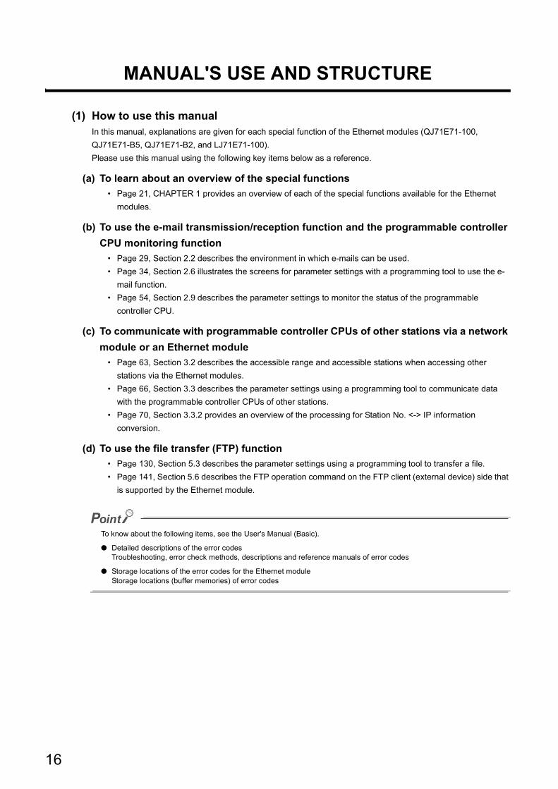
(1) How to use this manualIn this manual, explanations are given for each special function of the Ethernet modules (QJ71E71-100,
QJ71E71-B5, QJ71E71-B2, and LJ71E71-100).
Please use this manual using the following key items below as a reference.
(a) To learn about an overview of the special functions
• Page 21, CHAPTER 1 provides an overview of each of the special functions available for the Ethernet
modules.
(b) To use the e-mail transmission/reception function and the programmable controller
CPU monitoring function
• Page 29, Section 2.2 describes the environment in which e-mails can be used.
• Page 34, Section 2.6 illustrates the screens for parameter settings with a programming tool to use the e-
mail function.
• Page 54, Section 2.9 describes the parameter settings to monitor the status of the programmable
controller CPU.
(c) To communicate with programmable controller CPUs of other stations via a network
module or an Ethernet module
• Page 63, Section 3.2 describes the accessible range and accessible stations when accessing other
stations via the Ethernet modules.
• Page 66, Section 3.3 describes the parameter settings using a programming tool to communicate data
with the programmable controller CPUs of other stations.
• Page 70, Section 3.3.2 provides an overview of the processing for Station No. <-> IP information
conversion.
(d) To use the file transfer (FTP) function
• Page 130, Section 5.3 describes the parameter settings using a programming tool to transfer a file.
• Page 141, Section 5.6 describes the FTP operation command on the FTP client (external device) side that
is supported by the Ethernet module.
To know about the following items, see the User's Manual (Basic).
● Detailed descriptions of the error codesTroubleshooting, error check methods, descriptions and reference manuals of error codes
● Storage locations of the error codes for the Ethernet moduleStorage locations (buffer memories) of error codes
16

(2) Structure of this manual
(a) Setting Parameters with a programming tool
• By setting parameters with a programming tool, the sequence programs for communicating with external
devices can be simplified in the Ethernet module.
• In this manual, parameter settings using a programming tool are explained in detail for each item
displayed on the setting screens.*1
• For details on the types of the setting screens, objectives of the settings, the setting items and an outline of
the setting operation using a programming tool, see the User's Manual (Basic).
*1 Refer to the chapters related to the functions to be used and set the required parameters. Then load the set parameters to the programmable controller CPU of a station where an Ethernet module is connected.
17
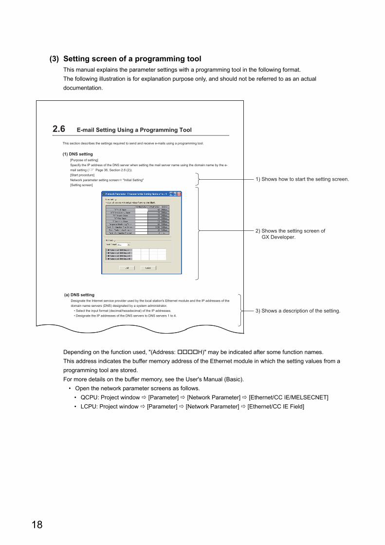
(3) Setting screen of a programming toolThis manual explains the parameter settings with a programming tool in the following format.
The following illustration is for explanation purpose only, and should not be referred to as an actual
documentation.
Depending on the function used, "(Address: H)" may be indicated after some function names.
This address indicates the buffer memory address of the Ethernet module in which the setting values from a
programming tool are stored.
For more details on the buffer memory, see the User's Manual (Basic).
• Open the network parameter screens as follows.
• QCPU: Project window [Parameter] [Network Parameter] [Ethernet/CC IE/MELSECNET]
• LCPU: Project window [Parameter] [Network Parameter] [Ethernet/CC IE Field]
3) Shows a description of the setting.
1) Shows how to start the setting screen.
2) Shows the setting screen ofGX Developer.
2.6 E-mail Setting Using a Programming Tool
This section describes the settings required to send and receive e-mails using a programming tool.
(1) DNS setting[Purpose of setting]Specify the IP address of the DNS server when setting the mail server name using the domain name by the e-mail setting (� Page 36, Section 2.6 (2)).[Start procedure]Network parameter setting screen � "Initial Setting"[Setting screen]
(a) DNS settingDesignate the Internet service provider used by the local station's Ethernet module and the IP addresses of the domain name servers (DNS) designated by a system administrator.
• Select the input format (decimal/hexadecimal) of the IP addresses.• Designate the IP addresses of the DNS servers to DNS servers 1 to 4.
18
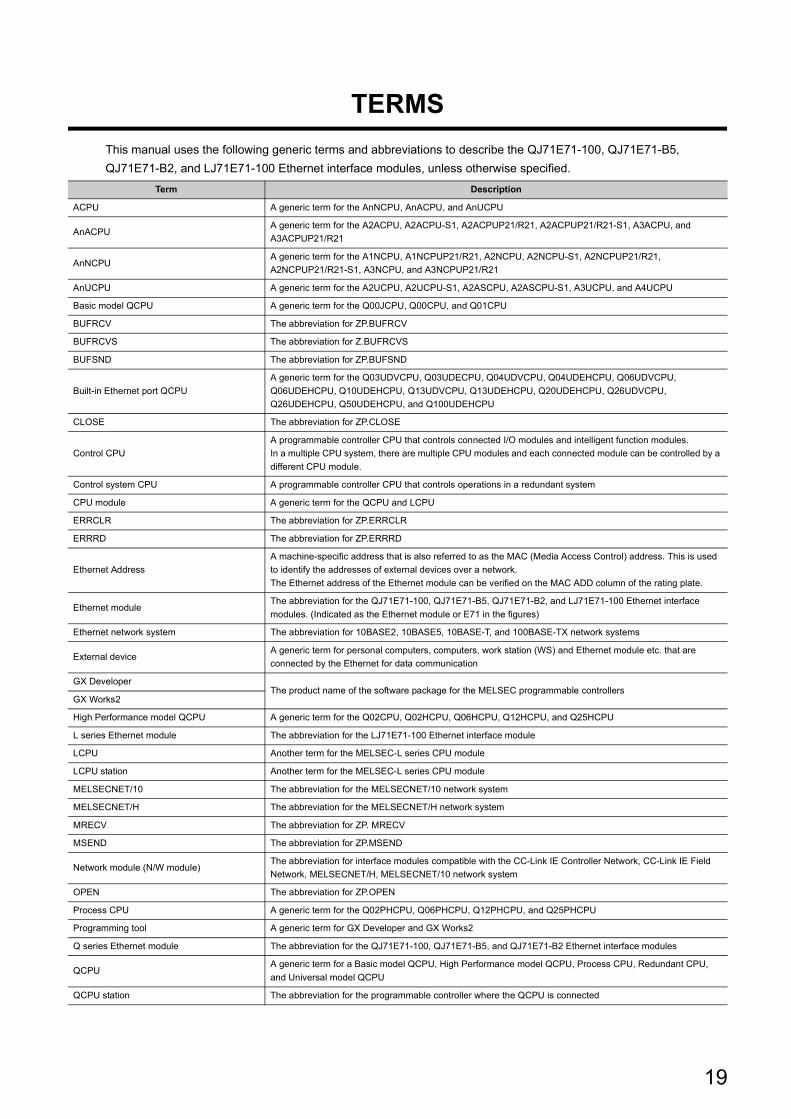
TERMS
This manual uses the following generic terms and abbreviations to describe the QJ71E71-100, QJ71E71-B5,
QJ71E71-B2, and LJ71E71-100 Ethernet interface modules, unless otherwise specified.
Term Description
ACPU A generic term for the AnNCPU, AnACPU, and AnUCPU
AnACPUA generic term for the A2ACPU, A2ACPU-S1, A2ACPUP21/R21, A2ACPUP21/R21-S1, A3ACPU, and
A3ACPUP21/R21
AnNCPUA generic term for the A1NCPU, A1NCPUP21/R21, A2NCPU, A2NCPU-S1, A2NCPUP21/R21,
A2NCPUP21/R21-S1, A3NCPU, and A3NCPUP21/R21
AnUCPU A generic term for the A2UCPU, A2UCPU-S1, A2ASCPU, A2ASCPU-S1, A3UCPU, and A4UCPU
Basic model QCPU A generic term for the Q00JCPU, Q00CPU, and Q01CPU
BUFRCV The abbreviation for ZP.BUFRCV
BUFRCVS The abbreviation for Z.BUFRCVS
BUFSND The abbreviation for ZP.BUFSND
Built-in Ethernet port QCPU
A generic term for the Q03UDVCPU, Q03UDECPU, Q04UDVCPU, Q04UDEHCPU, Q06UDVCPU,
Q06UDEHCPU, Q10UDEHCPU, Q13UDVCPU, Q13UDEHCPU, Q20UDEHCPU, Q26UDVCPU,
Q26UDEHCPU, Q50UDEHCPU, and Q100UDEHCPU
CLOSE The abbreviation for ZP.CLOSE
Control CPU
A programmable controller CPU that controls connected I/O modules and intelligent function modules.
In a multiple CPU system, there are multiple CPU modules and each connected module can be controlled by a
different CPU module.
Control system CPU A programmable controller CPU that controls operations in a redundant system
CPU module A generic term for the QCPU and LCPU
ERRCLR The abbreviation for ZP.ERRCLR
ERRRD The abbreviation for ZP.ERRRD
Ethernet Address
A machine-specific address that is also referred to as the MAC (Media Access Control) address. This is used
to identify the addresses of external devices over a network.
The Ethernet address of the Ethernet module can be verified on the MAC ADD column of the rating plate.
Ethernet moduleThe abbreviation for the QJ71E71-100, QJ71E71-B5, QJ71E71-B2, and LJ71E71-100 Ethernet interface
modules. (Indicated as the Ethernet module or E71 in the figures)
Ethernet network system The abbreviation for 10BASE2, 10BASE5, 10BASE-T, and 100BASE-TX network systems
External deviceA generic term for personal computers, computers, work station (WS) and Ethernet module etc. that are
connected by the Ethernet for data communication
GX DeveloperThe product name of the software package for the MELSEC programmable controllers
GX Works2
High Performance model QCPU A generic term for the Q02CPU, Q02HCPU, Q06HCPU, Q12HCPU, and Q25HCPU
L series Ethernet module The abbreviation for the LJ71E71-100 Ethernet interface module
LCPU Another term for the MELSEC-L series CPU module
LCPU station Another term for the MELSEC-L series CPU module
MELSECNET/10 The abbreviation for the MELSECNET/10 network system
MELSECNET/H The abbreviation for the MELSECNET/H network system
MRECV The abbreviation for ZP. MRECV
MSEND The abbreviation for ZP.MSEND
Network module (N/W module)The abbreviation for interface modules compatible with the CC-Link IE Controller Network, CC-Link IE Field
Network, MELSECNET/H, MELSECNET/10 network system
OPEN The abbreviation for ZP.OPEN
Process CPU A generic term for the Q02PHCPU, Q06PHCPU, Q12PHCPU, and Q25PHCPU
Programming tool A generic term for GX Developer and GX Works2
Q series Ethernet module The abbreviation for the QJ71E71-100, QJ71E71-B5, and QJ71E71-B2 Ethernet interface modules
QCPUA generic term for a Basic model QCPU, High Performance model QCPU, Process CPU, Redundant CPU,
and Universal model QCPU
QCPU station The abbreviation for the programmable controller where the QCPU is connected
19
QnACPUA generic term for the Q2ACPU, Q2ACPU-S1, Q2ASCPU, Q2ASCPU-S1, Q2ASHCPU, Q2ASHCPU-S1,
QA3ACPU, Q4ACPU, and Q4ARCPU
QnUDVCPU A generic term for the Q03UDVCPU, Q04UDVCPU, Q06UDVCPU, Q13UDVCPU, and Q26UDVCPU
READ The abbreviation for JP.READ and GP.READ
RECV The abbreviation for JP.RECV and GP.RECV
RECVS The abbreviation for Z.RECVS
Redundant CPU A generic term for the Q12PRHCPU and Q25PRHCPU
Reference Manual The abbreviation for the MELSEC Communication Protocol Reference Manual
REQ The abbreviation for J.REQ, JP.REQ, G.REQ and GP.REQ
Safety CPU A generic term for the QS001CPU
SEND The abbreviation for JP.SEND and GP.SEND
SREAD The abbreviation for JP.SREAD and GP.SREAD
Standby system CPUA programmable controller CPU where the system B connector of a tracking cable is connected in a redundant
system
SWRITE The abbreviation for JP.SWRITE and GP.SWRITE
System A CPUA programmable controller CPU where the system A connector of a tracking cable is connected in a redundant
system
System B CPUA programmable controller CPU where the system B connector of a tracking cable is connected in a redundant
system
UINI The abbreviation for ZP.UINI
Universal model QCPU
A generic term for the Q00UJCPU, Q00UCPU, Q01UCPU, Q02UCPU, Q03UDCPU, Q03UDVCPU,
Q03UDECPU, Q04UDHCPU, Q04UDVCPU, Q04UDEHCPU, Q06UDHCPU, Q06UDVCPU, Q06UDEHCPU,
Q10UDHCPU, Q10UDEHCPU, Q13UDHCPU, Q13UDVCPU, Q13UDEHCPU, Q20UDHCPU, Q20UDEHCPU,
Q26UDHCPU, Q26UDVCPU, Q26UDEHCPU, Q50UDEHCPU, and Q100UDEHCPU
User's Manual (Application) The abbreviation for the MELSEC-Q/L Ethernet Interface Module User's Manual (Application)
User's Manual (Basic)The abbreviation for the Q Corresponding Ethernet Interface Module User's Manual (Basic) and MELSEC-L
Ethernet Interface Module User's Manual (Basic)
User's Manual (Web function) The abbreviation for the MELSEC-Q/L Ethernet Interface Module User's Manual (Web function)
WRITE The abbreviation for JP.WRITE and GP.WRITE
ZNRD The abbreviation for J.ZNRD and JP.ZNRD
ZNWR The abbreviation for J.ZNWR and JP.ZNWR
Term Description
20
CHAPTER 1 OVERVIEW
1
1.1
Ove
rview
CHAPTER 1 OVERVIEW
This manual describes the special functions of an Ethernet interface module (hereinafter, abbreviated as Ethernet
module). When applying the following program examples to the actual system, make sure to examine the applicability
and confirm that it will not cause system control problems.
This chapter describes an overview of the special functions that are available for the Ethernet module.
1.1 Overview
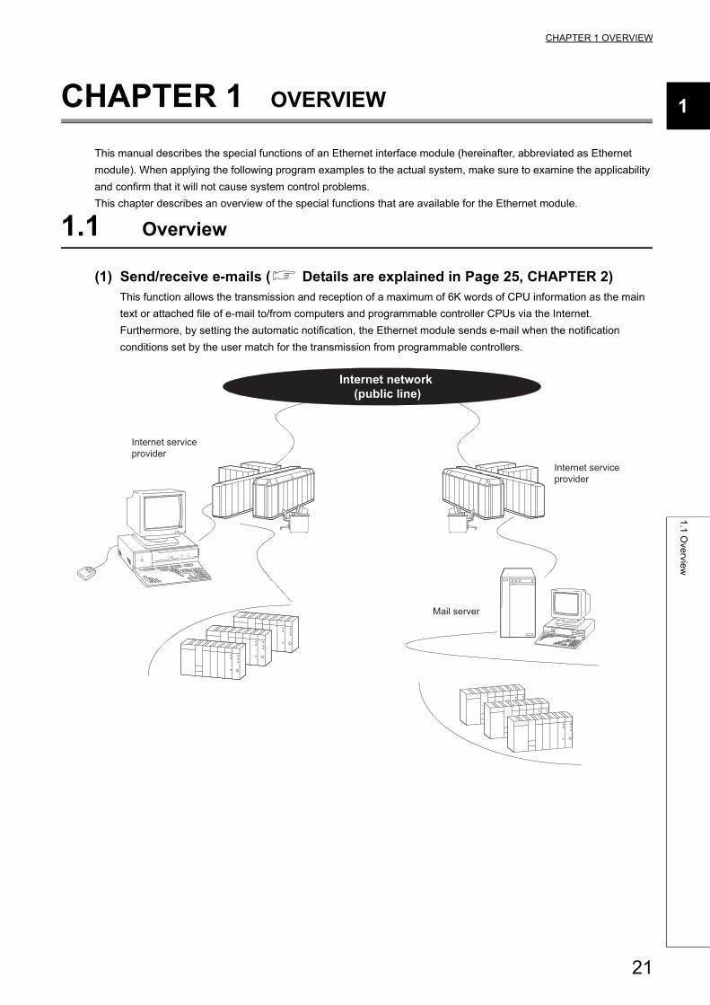
(1) Send/receive e-mails ( Details are explained in Page 25, CHAPTER 2)This function allows the transmission and reception of a maximum of 6K words of CPU information as the main
text or attached file of e-mail to/from computers and programmable controller CPUs via the Internet.
Furthermore, by setting the automatic notification, the Ethernet module sends e-mail when the notification
conditions set by the user match for the transmission from programmable controllers.
Mail server
Internet service provider
Internet network (public line)
Internet service provider
21
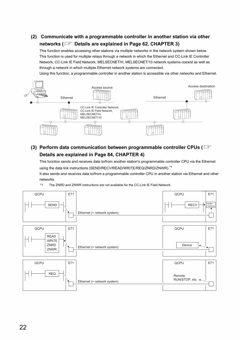
(2) Communicate with a programmable controller in another station via other
networks ( Details are explained in Page 62, CHAPTER 3)This function enables accessing other stations via multiple networks in the network system shown below.
This function is used for multiple relays through a network in which the Ethernet and CC-Link IE Controller
Network, CC-Link IE Field Network, MELSECNET/H, MELSECNET/10 network systems coexist as well as
through a network in which multiple Ethernet network systems are connected.
Using this function, a programmable controller in another station is accessible via other networks and Ethernet.
(3) Perform data communication between programmable controller CPUs (
Details are explained in Page 84, CHAPTER 4)This function sends and receives data to/from another station's programmable controller CPU via the Ethernet
using the data link instructions (SEND/RECV/READ/WRITE/REQ/ZNRD/ZNWR).*1
It also sends and receives data to/from a programmable controller CPU in another station via Ethernet and other
networks.
*1 The ZNRD and ZNWR instructions are not available for the CC-Link IE Field Network.
Ethernet Ethernet
Access source Access destination
CC-Link IE Controller Network, CC-Link IE Field Network, MELSECNET/H, MELSECNET/10
QCPU E71 QCPU E71
QCPU E71 QCPU E71
QCPU E71 QCPU E71
SEND
READWRITEZNRDZNWR
REQ
RECV
Ethernet (+ network system)
Ethernet (+ network system)
Ethernet (+ network system)
Remote RUN/STOP, etc.
Device
Buffer memory
22
CHAPTER 1 OVERVIEW
1
1.1
Ove
rview
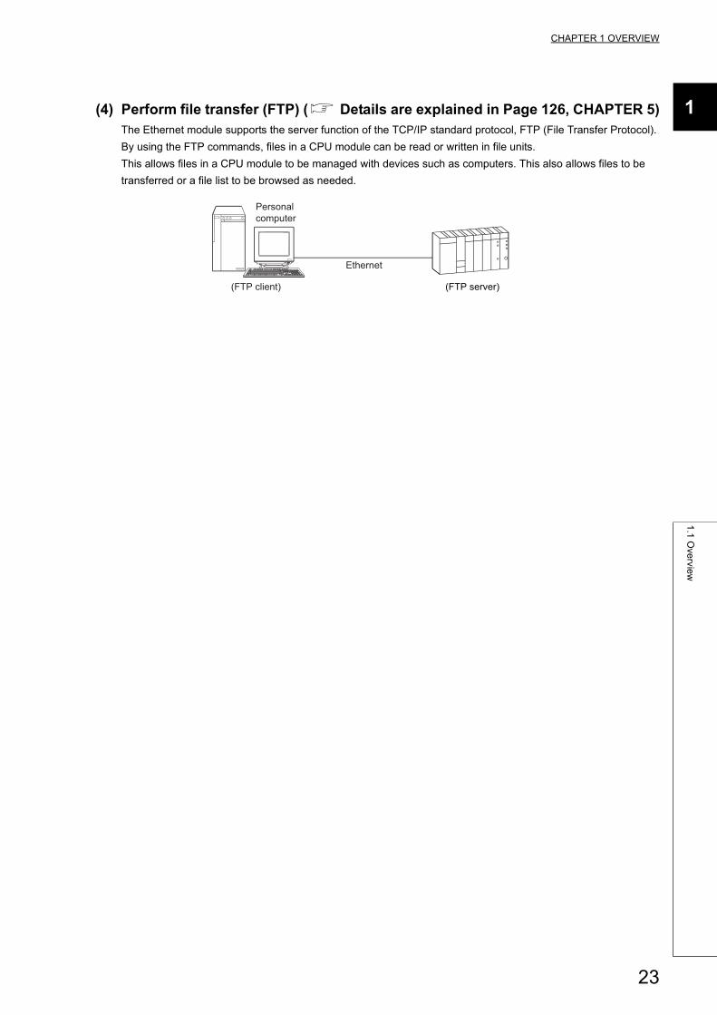
(4) Perform file transfer (FTP) ( Details are explained in Page 126, CHAPTER 5)The Ethernet module supports the server function of the TCP/IP standard protocol, FTP (File Transfer Protocol).
By using the FTP commands, files in a CPU module can be read or written in file units.
This allows files in a CPU module to be managed with devices such as computers. This also allows files to be
transferred or a file list to be browsed as needed.
Ethernet
Personal computer
(FTP client) (FTP server)
23
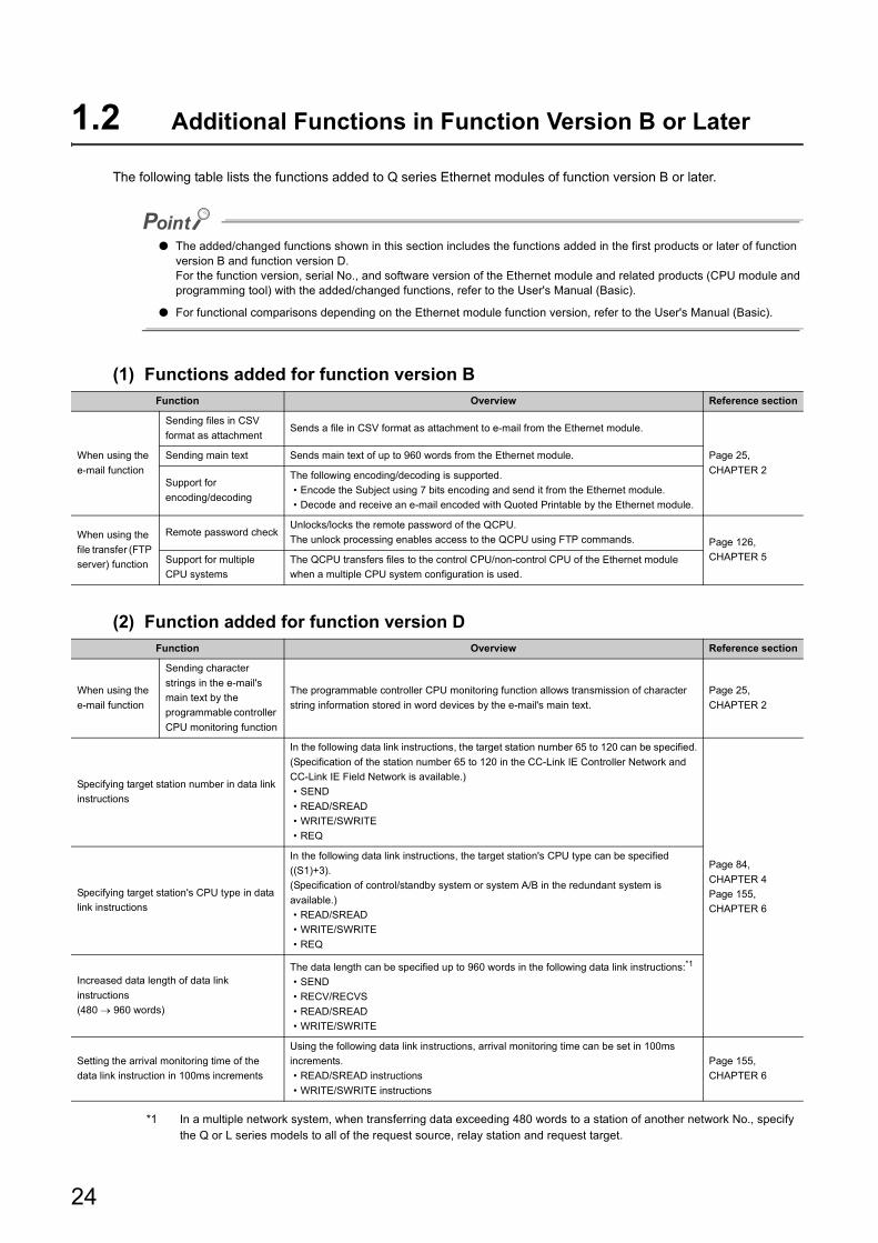
1.2 Additional Functions in Function Version B or Later
The following table lists the functions added to Q series Ethernet modules of function version B or later.
● The added/changed functions shown in this section includes the functions added in the first products or later of function version B and function version D.For the function version, serial No., and software version of the Ethernet module and related products (CPU module and programming tool) with the added/changed functions, refer to the User's Manual (Basic).
● For functional comparisons depending on the Ethernet module function version, refer to the User's Manual (Basic).
(1) Functions added for function version B
(2) Function added for function version D
*1 In a multiple network system, when transferring data exceeding 480 words to a station of another network No., specify the Q or L series models to all of the request source, relay station and request target.
Function Overview Reference section
When using the
e-mail function
Sending files in CSV
format as attachmentSends a file in CSV format as attachment to e-mail from the Ethernet module.
Page 25,
CHAPTER 2
Sending main text Sends main text of up to 960 words from the Ethernet module.
Support for
encoding/decoding
The following encoding/decoding is supported.
• Encode the Subject using 7 bits encoding and send it from the Ethernet module.
• Decode and receive an e-mail encoded with Quoted Printable by the Ethernet module.
When using the
file transfer (FTP
server) function
Remote password checkUnlocks/locks the remote password of the QCPU.
The unlock processing enables access to the QCPU using FTP commands. Page 126,
CHAPTER 5Support for multiple
CPU systems
The QCPU transfers files to the control CPU/non-control CPU of the Ethernet module
when a multiple CPU system configuration is used.
Function Overview Reference section
When using the
e-mail function
Sending character
strings in the e-mail's
main text by the
programmable controller
CPU monitoring function
The programmable controller CPU monitoring function allows transmission of character
string information stored in word devices by the e-mail's main text.
Page 25,
CHAPTER 2
Specifying target station number in data link
instructions
In the following data link instructions, the target station number 65 to 120 can be specified.
(Specification of the station number 65 to 120 in the CC-Link IE Controller Network and
CC-Link IE Field Network is available.)
• SEND
• READ/SREAD
• WRITE/SWRITE
• REQ
Page 84,
CHAPTER 4
Page 155,
CHAPTER 6
Specifying target station's CPU type in data
link instructions
In the following data link instructions, the target station's CPU type can be specified
((S1)+3).
(Specification of control/standby system or system A/B in the redundant system is
available.)
• READ/SREAD
• WRITE/SWRITE
• REQ
Increased data length of data link
instructions
(480 960 words)
The data length can be specified up to 960 words in the following data link instructions:*1
• SEND
• RECV/RECVS
• READ/SREAD
• WRITE/SWRITE
Setting the arrival monitoring time of the
data link instruction in 100ms increments
Using the following data link instructions, arrival monitoring time can be set in 100ms
increments.
• READ/SREAD instructions
• WRITE/SWRITE instructions
Page 155,
CHAPTER 6
24
CHAPTER 2 USING THE E-MAIL FUNCTION
2
2.1
E-m
ail F
un
ction
CHAPTER 2 USING THE E-MAIL FUNCTION
2.1 E-mail Function
The e-mail function sends and receives CPU information (programmable controller CPU status and device values)
to/from PCs or programmable controller CPUs in remote locations via the Internet.
The following two methods are available to send/receive e-mail using this function.
(1) Sending/receiving e-mail by the programmable controller CPUExecuted by a sequence program using dedicated instructions.
(2) Sending e-mail using the Ethernet module's programmable controller CPU
monitor functionExecuted by the Ethernet module according to the Ethernet module parameter setting (news setting) of a
programming tool.
2.1.1 Sending/receiving e-mail by the programmable controller CPU
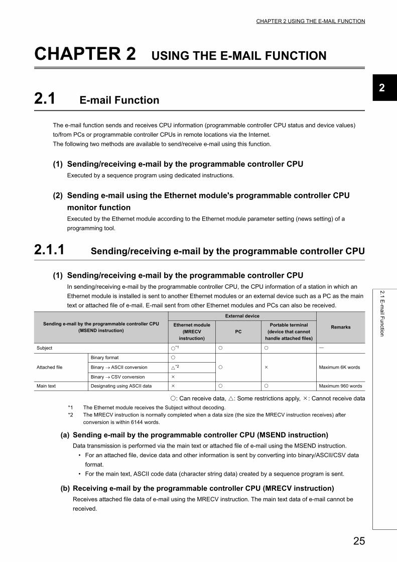
(1) Sending/receiving e-mail by the programmable controller CPUIn sending/receiving e-mail by the programmable controller CPU, the CPU information of a station in which an
Ethernet module is installed is sent to another Ethernet modules or an external device such as a PC as the main
text or attached file of e-mail. E-mail sent from other Ethernet modules and PCs can also be received.
: Can receive data, : Some restrictions apply, : Cannot receive data
*1 The Ethernet module receives the Subject without decoding.*2 The MRECV instruction is normally completed when a data size (the size the MRECV instruction receives) after
conversion is within 6144 words.
(a) Sending e-mail by the programmable controller CPU (MSEND instruction)
Data transmission is performed via the main text or attached file of e-mail using the MSEND instruction.
• For an attached file, device data and other information is sent by converting into binary/ASCII/CSV data
format.
• For the main text, ASCII code data (character string data) created by a sequence program is sent.
(b) Receiving e-mail by the programmable controller CPU (MRECV instruction)
Receives attached file data of e-mail using the MRECV instruction. The main text data of e-mail cannot be
received.
Sending e-mail by the programmable controller CPU
(MSEND instruction)
External device
RemarksEthernet module
(MRECV
instruction)
PC
Portable terminal
(device that cannot
handle attached files)
Subject *1
Attached file
Binary format
Maximum 6K wordsBinary ASCII conversion *2
Binary CSV conversion
Main text Designating using ASCII data Maximum 960 words
25
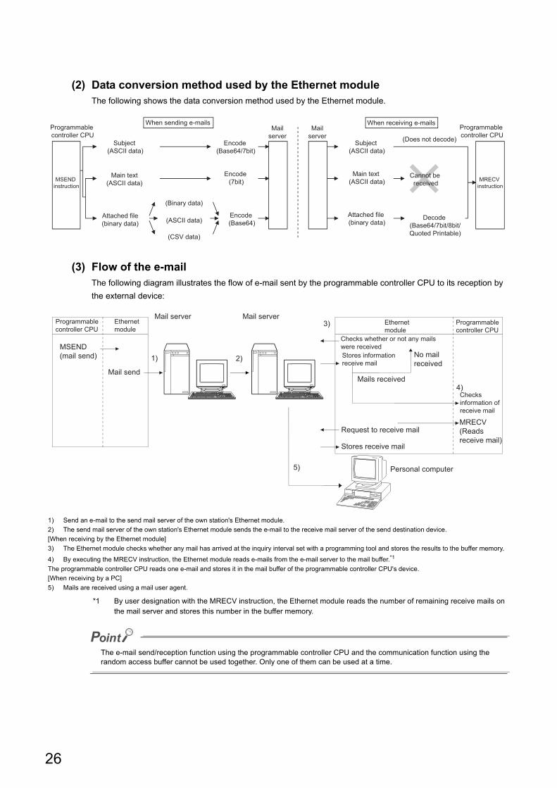
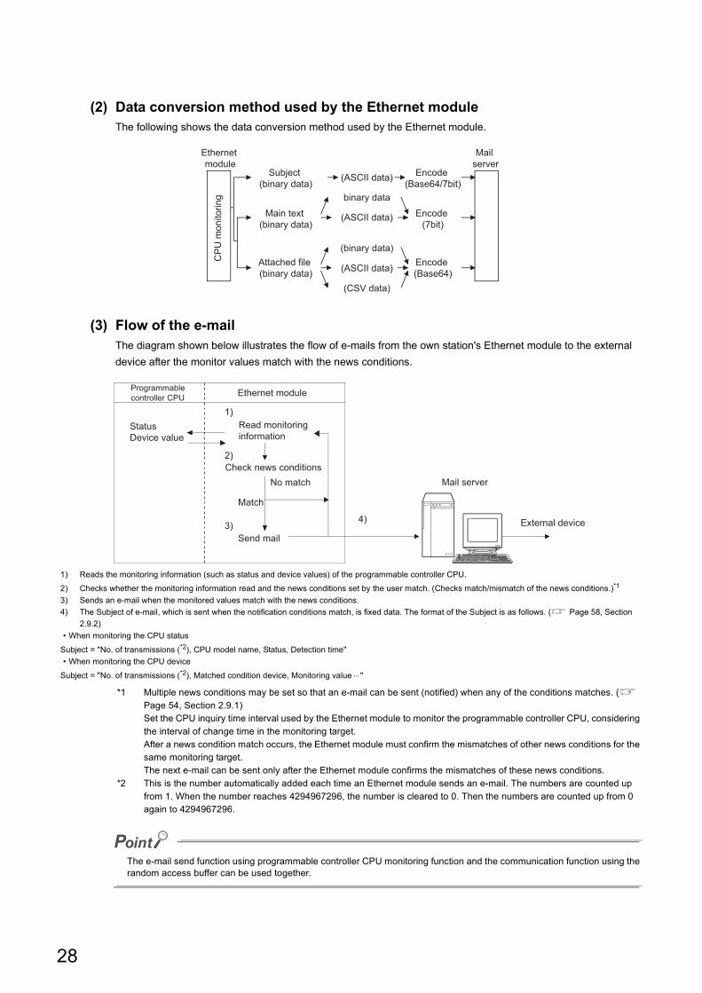
(2) Data conversion method used by the Ethernet moduleThe following shows the data conversion method used by the Ethernet module.
(3) Flow of the e-mailThe following diagram illustrates the flow of e-mail sent by the programmable controller CPU to its reception by
the external device:
*1 By user designation with the MRECV instruction, the Ethernet module reads the number of remaining receive mails on the mail server and stores this number in the buffer memory.
The e-mail send/reception function using the programmable controller CPU and the communication function using the random access buffer cannot be used together. Only one of them can be used at a time.
1) Send an e-mail to the send mail server of the own station's Ethernet module.
2) The send mail server of the own station's Ethernet module sends the e-mail to the receive mail server of the send destination device.
[When receiving by the Ethernet module]
3) The Ethernet module checks whether any mail has arrived at the inquiry interval set with a programming tool and stores the results to the buffer memory.
4) By executing the MRECV instruction, the Ethernet module reads e-mails from the e-mail server to the mail buffer.*1
The programmable controller CPU reads one e-mail and stores it in the mail buffer of the programmable controller CPU's device.
[When receiving by a PC]
5) Mails are received using a mail user agent.
When sending e-mails When receiving e-mails
MSEND instruction
Subject (ASCII data)
Main text (ASCII data)
Attached file (binary data)
(Binary data)
(ASCII data)
(CSV data)
(Does not decode)
Encode (Base64)
Mail server
Mail server
Attached file (binary data)
Subject (ASCII data)
Main text (ASCII data)
Encode (7bit)
Encode (Base64/7bit)
Programmable controller CPU
Programmable controller CPU
MRECV instruction
Decode (Base64/7bit/8bit/Quoted Printable)
Cannot be received
1) 2)
5)
3)
4)
Programmable controller CPU
Mail server
Personal computer
Stores receive mail
Request to receive mail
Mails received
Mail serverEthernet module
MSEND (mail send)
Mail send
Ethernet module
Programmable controller CPU
Checks whether or not any mails were receivedStores information receive mail
No mail received
Checks information of receive mail
MRECV (Reads receive mail)
26
CHAPTER 2 USING THE E-MAIL FUNCTION
2
2.1
E-m
ail F
un
ction
2.1.2 Sending e-mail using the programmable controller CPU monitor function
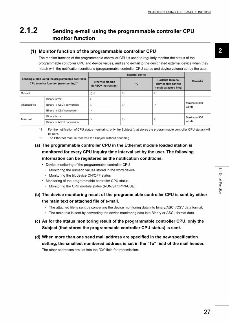
(1) Monitor function of the programmable controller CPUThe monitor function of the programmable controller CPU is used to regularly monitor the status of the
programmable controller CPU and device values, and send e-mail to the designated external device when they
match with the notification conditions (programmable controller CPU status and device values) set by the user.
*1 For the notification of CPU status monitoring, only the Subject (that stores the programmable controller CPU status) will be sent.
*2 The Ethernet module receives the Subject without decoding.
(a) The programmable controller CPU in the Ethernet module loaded station is
monitored for every CPU inquiry time interval set by the user. The following
information can be registered as the notification conditions.
• Device monitoring of the programmable controller CPU
• Monitoring the numeric values stored in the word device
• Monitoring the bit device ON/OFF status
• Monitoring of the programmable controller CPU status
• Monitoring the CPU module status (RUN/STOP/PAUSE)
(b) The device monitoring result of the programmable controller CPU is sent by either
the main text or attached file of e-mail.
• The attached file is sent by converting the device monitoring data into binary/ASCII/CSV data format.
• The main text is sent by converting the device monitoring data into Binary or ASCII format data.
(c) As for the status monitoring result of the programmable controller CPU, only the
Subject (that stores the programmable controller CPU status) is sent.
(d) When more than one send mail address are specified in the new specification
setting, the smallest numbered address is set in the "To" field of the mail header.
The other addresses are set into the "Cc" field for transmission.
Sending e-mail using the programmable controller
CPU monitor function (news setting)*1
External device
RemarksEthernet module
(MRECV instruction)PC
Portable terminal
(device that cannot
handle attached files)
Subject *2
Attached file
Binary format
Maximum 960
wordsBinary ASCII conversion
Binary CSV conversion
Main textBinary format
Maximum 960
wordsBinary ASCII conversion
27
(2) Data conversion method used by the Ethernet moduleThe following shows the data conversion method used by the Ethernet module.
(3) Flow of the e-mailThe diagram shown below illustrates the flow of e-mails from the own station's Ethernet module to the external
device after the monitor values match with the news conditions.
*1 Multiple news conditions may be set so that an e-mail can be sent (notified) when any of the conditions matches. ( Page 54, Section 2.9.1)Set the CPU inquiry time interval used by the Ethernet module to monitor the programmable controller CPU, considering the interval of change time in the monitoring target.After a news condition match occurs, the Ethernet module must confirm the mismatches of other news conditions for the same monitoring target.The next e-mail can be sent only after the Ethernet module confirms the mismatches of these news conditions.
*2 This is the number automatically added each time an Ethernet module sends an e-mail. The numbers are counted up from 1. When the number reaches 4294967296, the number is cleared to 0. Then the numbers are counted up from 0 again to 4294967296.
The e-mail send function using programmable controller CPU monitoring function and the communication function using the random access buffer can be used together.
1) Reads the monitoring information (such as status and device values) of the programmable controller CPU.
2) Checks whether the monitoring information read and the news conditions set by the user match. (Checks match/mismatch of the news conditions.)*1
3) Sends an e-mail when the monitored values match with the news conditions.
4) The Subject of e-mail, which is sent when the notification conditions match, is fixed data. The format of the Subject is as follows. ( Page 58, Section
2.9.2)
• When monitoring the CPU status
Subject = "No. of transmissions (*2), CPU model name, Status, Detection time"
• When monitoring the CPU device
Subject = "No. of transmissions (*2), Matched condition device, Monitoring value "
CP
U m
onito
ring
Encode (Base64)
Encode (7bit)
Encode (Base64/7bit)
Ethernet module
Mail server
Subject (binary data)
Main text (binary data)
Attached file (binary data)
(CSV data)
(ASCII data)
(binary data)
(ASCII data)
binary data
(ASCII data)
1)
2)
3)4) External device
Match
Mail server
Programmable controller CPU Ethernet module
Status Device value
Read monitoring information
Check news conditionsNo match
Send mail
28
CHAPTER 2 USING THE E-MAIL FUNCTION
2
2.2
Co
nfig
ura
tion
an
d E
nviro
nm
en
t of th
e A
pp
licab
le S
ystem
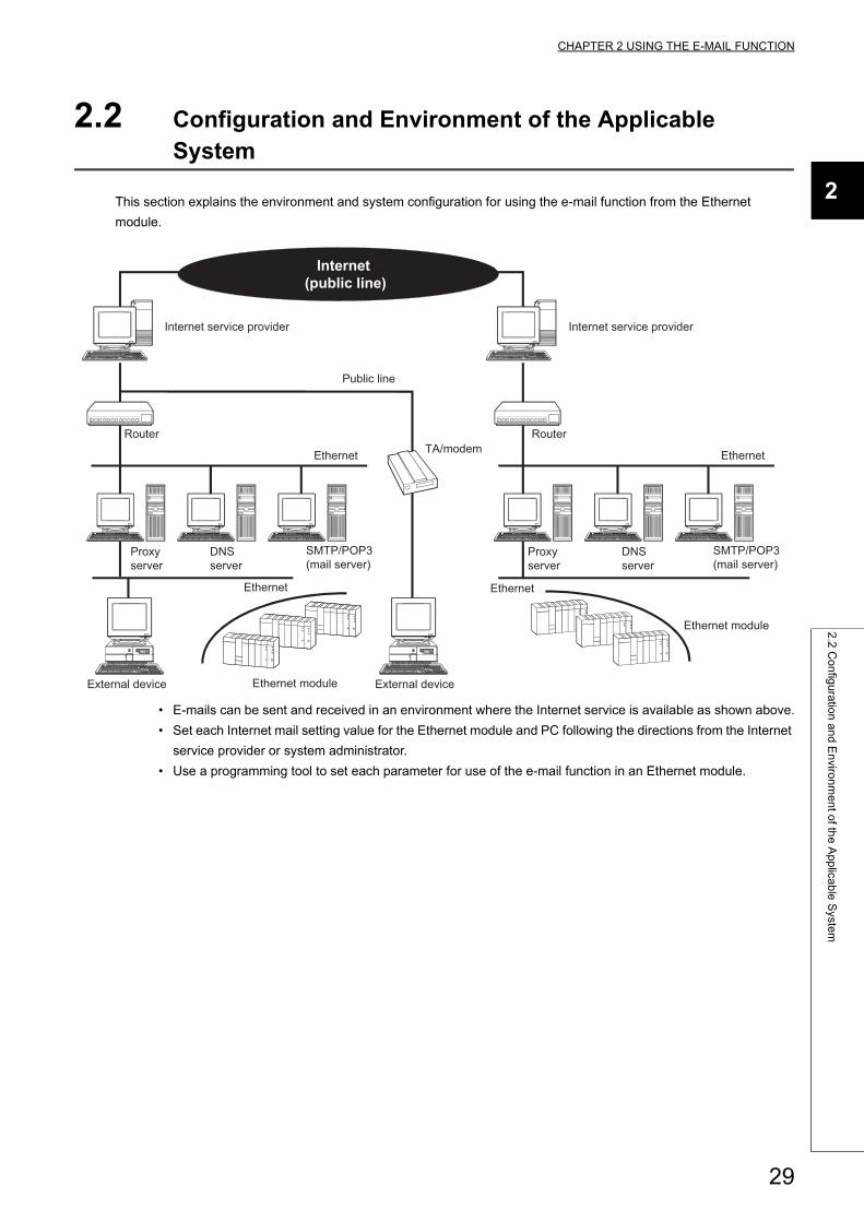
2.2 Configuration and Environment of the Applicable System
This section explains the environment and system configuration for using the e-mail function from the Ethernet
module.
• E-mails can be sent and received in an environment where the Internet service is available as shown above.
• Set each Internet mail setting value for the Ethernet module and PC following the directions from the Internet
service provider or system administrator.
• Use a programming tool to set each parameter for use of the e-mail function in an Ethernet module.
Ethernet moduleExternal device
TA/modem
Internet service provider
DNS server
Proxy server
SMTP/POP3 (mail server)
Ethernet
Ethernet
Ethernet module
Ethernet
Public line
Internet service provider
Router Router
Proxy server
DNS server
SMTP/POP3 (mail server)
Ethernet
External device
Internet (public line)
29
2.3 Precautions for Using the E-mail Function
The following explains precautions when using the e-mail function of the Ethernet module.
(1) Precautions regarding the system
(a) Design the system so that the entire system operates normally at all times when
sending/receiving e-mails to/from a running system and controlling the
programmable controller.
(b) In order to avoid programmable controller system malfunctions caused by
receptions of illegal e-mails from the outside sources, take precautions in
preventing illegal e-mails from being received on the mail served on the Ethernet
module side (using an anti-virus program, etc).
(2) Precautions regarding the external device
(a) E-mails can be sent to programmable controller CPU stations with Q series Ethernet
modules connected.
Note that A/QnA series Ethernet modules do not have the e-mail function; therefore, e-mails cannot be sent to
programmable controller CPU stations.
(b) To send files to the Ethernet module as attachments to e-mail, specify the encoding
method (Base 64/7 bits/8 bits/Quoted Printable) of the attached files.
(3) Common precautions
(a) The Ethernet module stores the data of attached files received from the external
device in the device specified by the MRECV instruction without converting it from
ASCII to binary.
(b) The maximum sizes of data that can be sent/received by the Ethernet module are as
follows:
• Data size of attached files: Up to 6K words
• Data size of main text: Up to 960 words
(c) Mails that are sent and received do not support encrypted data, compressed data,
and data conversion.
(d) When the external device could not be found in an e-mail sending from the Ethernet
module, the error code can be checked through the reception processing with the
MRECV instruction.
• If an external device cannot be found when sending e-mail using the MSEND instruction, failure of e-mail
transmission may not be recognized, depending on the operation of the mail server. Be sure to verify the
receiver's e-mail address in advance.
• Error codes are stored within the control data of the MRECV instruction. (For details on error codes, refer
to the User's Manual (Basic).)
30
CHAPTER 2 USING THE E-MAIL FUNCTION
2
2.3
Pre
cau
tion
s for U
sing
the
E-m
ail F
un
ction
(e) The e-mail function is supported for the SMTP and POP3 servers.
(f) When communication errors of e-mails cannot be checked by a dedicated
instruction, check the error codes stored in the mail send/reception error log area of
the buffer memory.
(g) If e-mails cannot be received, try one of the following.
• Execute the MRECV instruction once.
• Shorten the "Enquiry Interval" time in the e-mail settings of a programming tool.
• Check the number of incoming mails remaining on the mail server. (Can be checked with the buffer
memory address 5870H area.)
(h) When the receive data of an e-mail sent using the MSEND instruction is abnormal
(garbled characters, etc.), review the transmission data format (binary/ASCII/CSV)
designated with the MSEND instruction.
The Subject should be designated in ASCII code data. (It is not converted to ASCII format.)
(i) Confirm with a system administrator regarding the minimum time intervals for
accessing the mail server when sending mails, reading receive mails, and inquiring
whether or not there are receive mails.
Depending on the mail server's security setting, frequent access may be prohibited.
(j) The e-mail send/reception function using the programmable controller CPU and the
communication function using the random access buffer cannot be used together.
Only one of them can be used at a time.
The e-mail send function using programmable controller CPU monitoring function and the communication
function using the random access buffer can be used together.
(k) A Subject that has been sent by the MSEND instruction from an Ethernet module of
the following versions, cannot be received normally by the MRECV instruction.
• Ethernet modules with serial numbers where the first 5 digits are 03101 or less
Different methods are used for converting Subject data at send and reception. ( Page 26, Section 2.1.1 (3))
• When sending: Encodes the Subject and then send it.
• When receiving: Receives the Subject without decoding it.
31
2.4 E-mail Specifications
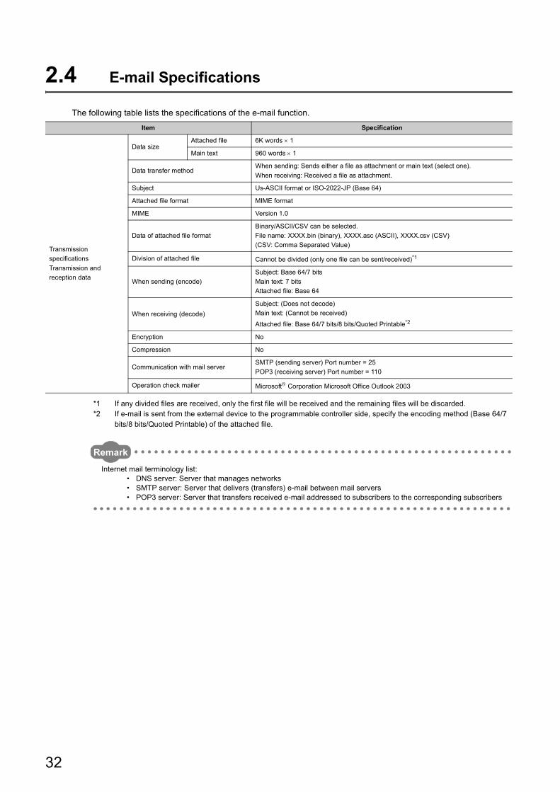
The following table lists the specifications of the e-mail function.
*1 If any divided files are received, only the first file will be received and the remaining files will be discarded.*2 If e-mail is sent from the external device to the programmable controller side, specify the encoding method (Base 64/7
bits/8 bits/Quoted Printable) of the attached file.
Remark
Internet mail terminology list:• DNS server: Server that manages networks• SMTP server: Server that delivers (transfers) e-mail between mail servers• POP3 server: Server that transfers received e-mail addressed to subscribers to the corresponding subscribers
Item Specification
Transmission
specifications
Transmission and
reception data
Data sizeAttached file 6K words 1
Main text 960 words 1
Data transfer methodWhen sending: Sends either a file as attachment or main text (select one).
When receiving: Received a file as attachment.
Subject Us-ASCII format or ISO-2022-JP (Base 64)
Attached file format MIME format
MIME Version 1.0
Data of attached file format
Binary/ASCII/CSV can be selected.
File name: XXXX.bin (binary), XXXX.asc (ASCII), XXXX.csv (CSV)
(CSV: Comma Separated Value)
Division of attached file Cannot be divided (only one file can be sent/received)*1
When sending (encode)
Subject: Base 64/7 bits
Main text: 7 bits
Attached file: Base 64
When receiving (decode)
Subject: (Does not decode)
Main text: (Cannot be received)
Attached file: Base 64/7 bits/8 bits/Quoted Printable*2
Encryption No
Compression No
Communication with mail serverSMTP (sending server) Port number = 25
POP3 (receiving server) Port number = 110
Operation check mailer Microsoft Corporation Microsoft Office Outlook 2003
32
CHAPTER 2 USING THE E-MAIL FUNCTION
2
2.5
Pro
cessin
g P
roce
du
re o
f the
E-m
ail F
un
ction
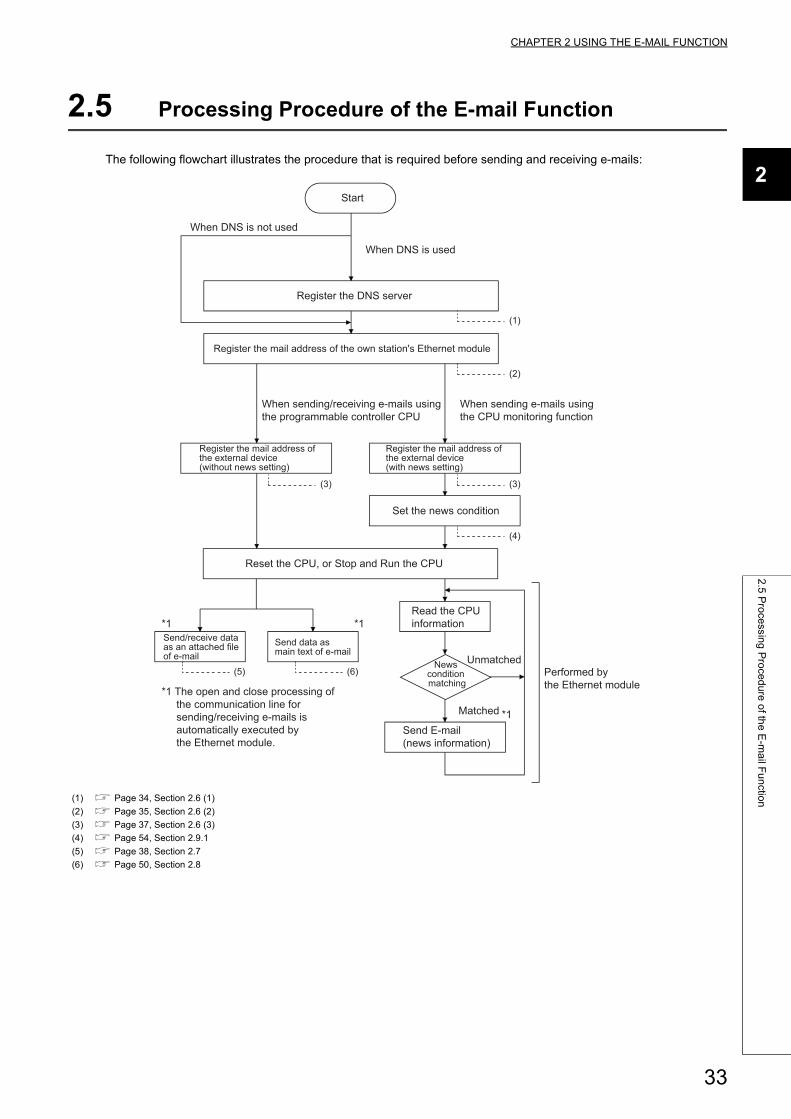
2.5 Processing Procedure of the E-mail Function
The following flowchart illustrates the procedure that is required before sending and receiving e-mails:
(1) Page 34, Section 2.6 (1)
(2) Page 35, Section 2.6 (2)
(3) Page 37, Section 2.6 (3)
(4) Page 54, Section 2.9.1
(5) Page 38, Section 2.7
(6) Page 50, Section 2.8
Send/receive data as an attached file of e-mail
*1
Send data as main text of e-mail
*1
*1 The open and close processing of the communication line for sending/receiving e-mails is automatically executed by the Ethernet module.
Read the CPU information
News condition matching
Send E-mail (news information)
Matched *1
Unmatched
Reset the CPU, or Stop and Run the CPU
Set the news condition
Register the mail address of the external device (with news setting)
Register the mail address of the external device (without news setting)
When sending e-mails usingthe CPU monitoring function
When sending/receiving e-mails using the programmable controller CPU
Register the mail address of the own station's Ethernet module
Register the DNS server
Start
Performed by the Ethernet module
When DNS is not used
When DNS is used
(4)
(3)(3)
(6)(5)
(2)
(1)
33
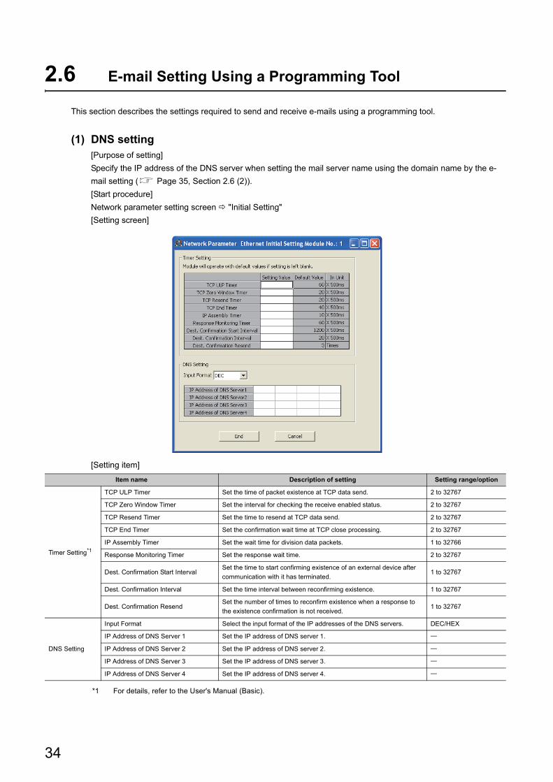
2.6 E-mail Setting Using a Programming Tool
This section describes the settings required to send and receive e-mails using a programming tool.
(1) DNS setting[Purpose of setting]
Specify the IP address of the DNS server when setting the mail server name using the domain name by the e-
mail setting ( Page 35, Section 2.6 (2)).
[Start procedure]
Network parameter setting screen "Initial Setting"
[Setting screen]
[Setting item]
*1 For details, refer to the User's Manual (Basic).
Item name Description of setting Setting range/option
Timer Setting*1
TCP ULP Timer Set the time of packet existence at TCP data send. 2 to 32767
TCP Zero Window Timer Set the interval for checking the receive enabled status. 2 to 32767
TCP Resend Timer Set the time to resend at TCP data send. 2 to 32767
TCP End Timer Set the confirmation wait time at TCP close processing. 2 to 32767
IP Assembly Timer Set the wait time for division data packets. 1 to 32766
Response Monitoring Timer Set the response wait time. 2 to 32767
Dest. Confirmation Start IntervalSet the time to start confirming existence of an external device after
communication with it has terminated.1 to 32767
Dest. Confirmation Interval Set the time interval between reconfirming existence. 1 to 32767
Dest. Confirmation ResendSet the number of times to reconfirm existence when a response to
the existence confirmation is not received.1 to 32767
DNS Setting
Input Format Select the input format of the IP addresses of the DNS servers. DEC/HEX
IP Address of DNS Server 1 Set the IP address of DNS server 1.
IP Address of DNS Server 2 Set the IP address of DNS server 2.
IP Address of DNS Server 3 Set the IP address of DNS server 3.
IP Address of DNS Server 4 Set the IP address of DNS server 4.
34
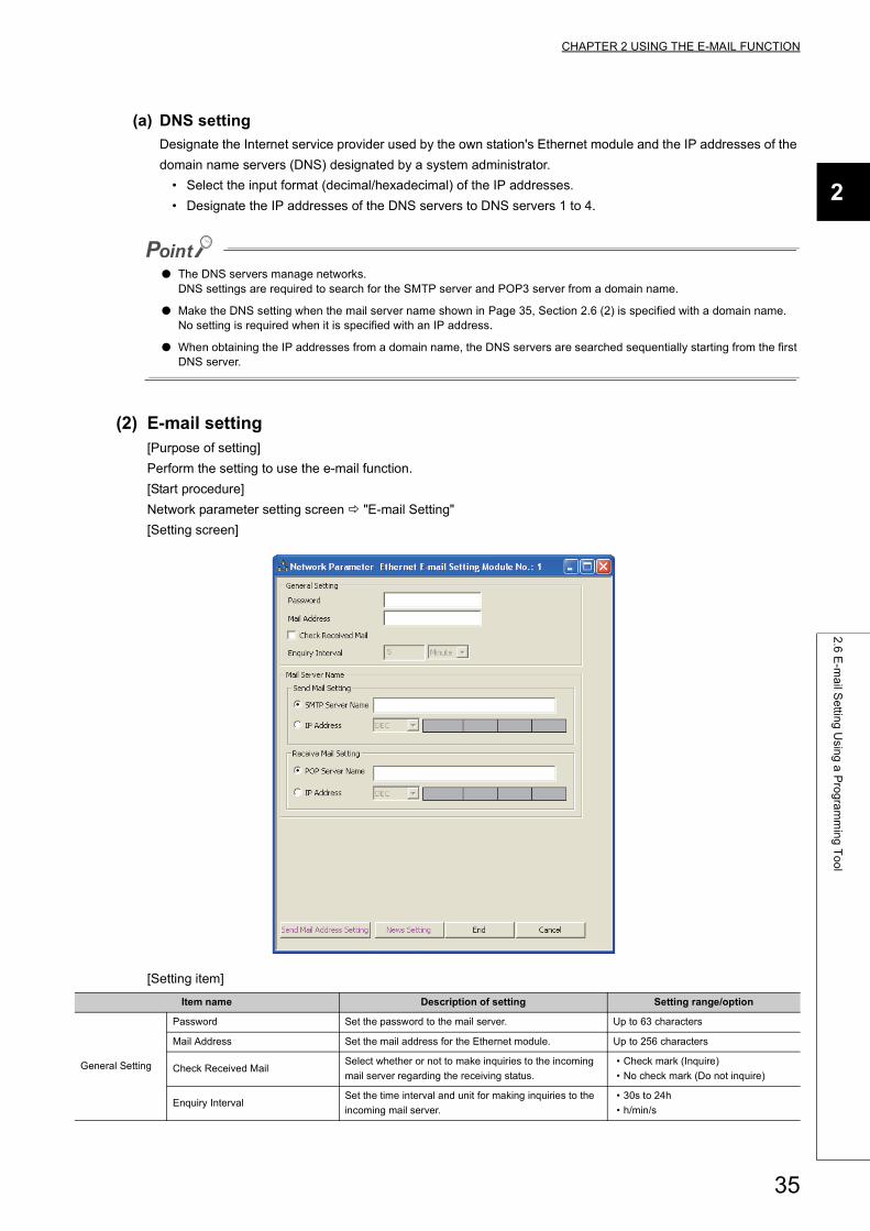
CHAPTER 2 USING THE E-MAIL FUNCTION
2
2.6
E-m
ail S
ettin
g U
sing
a P
rog
ram
min
g T
oo
l
(a) DNS setting
Designate the Internet service provider used by the own station's Ethernet module and the IP addresses of the
domain name servers (DNS) designated by a system administrator.
• Select the input format (decimal/hexadecimal) of the IP addresses.
• Designate the IP addresses of the DNS servers to DNS servers 1 to 4.
● The DNS servers manage networks.DNS settings are required to search for the SMTP server and POP3 server from a domain name.
● Make the DNS setting when the mail server name shown in Page 35, Section 2.6 (2) is specified with a domain name.No setting is required when it is specified with an IP address.
● When obtaining the IP addresses from a domain name, the DNS servers are searched sequentially starting from the first DNS server.
(2) E-mail setting[Purpose of setting]
Perform the setting to use the e-mail function.
[Start procedure]
Network parameter setting screen "E-mail Setting"
[Setting screen]
[Setting item]
Item name Description of setting Setting range/option
General Setting
Password Set the password to the mail server. Up to 63 characters
Mail Address Set the mail address for the Ethernet module. Up to 256 characters
Check Received MailSelect whether or not to make inquiries to the incoming
mail server regarding the receiving status.
• Check mark (Inquire)
• No check mark (Do not inquire)
Enquiry IntervalSet the time interval and unit for making inquiries to the
incoming mail server.
• 30s to 24h
• h/min/s
35
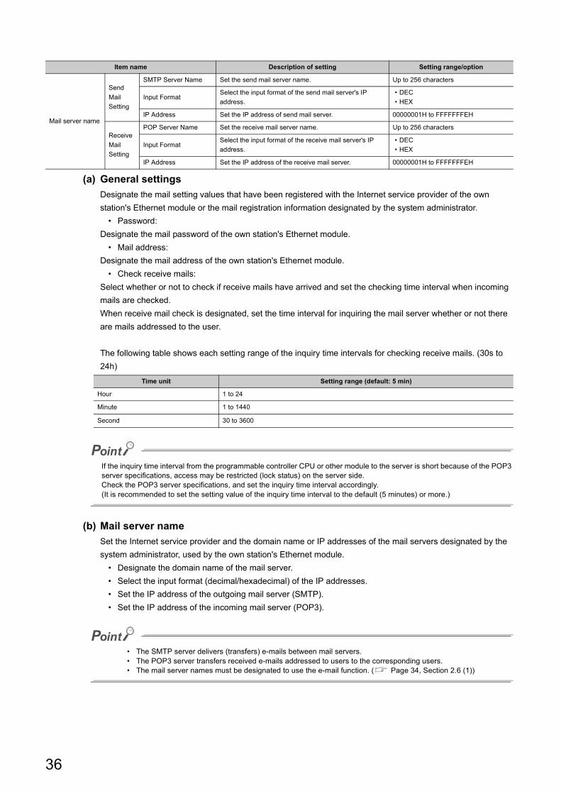
(a) General settings
Designate the mail setting values that have been registered with the Internet service provider of the own
station's Ethernet module or the mail registration information designated by the system administrator.
• Password:
Designate the mail password of the own station's Ethernet module.
• Mail address:
Designate the mail address of the own station's Ethernet module.
• Check receive mails:
Select whether or not to check if receive mails have arrived and set the checking time interval when incoming
mails are checked.
When receive mail check is designated, set the time interval for inquiring the mail server whether or not there
are mails addressed to the user.
The following table shows each setting range of the inquiry time intervals for checking receive mails. (30s to
24h)
If the inquiry time interval from the programmable controller CPU or other module to the server is short because of the POP3 server specifications, access may be restricted (lock status) on the server side.Check the POP3 server specifications, and set the inquiry time interval accordingly.(It is recommended to set the setting value of the inquiry time interval to the default (5 minutes) or more.)
(b) Mail server name
Set the Internet service provider and the domain name or IP addresses of the mail servers designated by the
system administrator, used by the own station's Ethernet module.
• Designate the domain name of the mail server.
• Select the input format (decimal/hexadecimal) of the IP addresses.
• Set the IP address of the outgoing mail server (SMTP).
• Set the IP address of the incoming mail server (POP3).
• The SMTP server delivers (transfers) e-mails between mail servers.• The POP3 server transfers received e-mails addressed to users to the corresponding users.• The mail server names must be designated to use the e-mail function. ( Page 34, Section 2.6 (1))
Mail server name
Send
Setting
SMTP Server Name Set the send mail server name. Up to 256 characters
Input FormatSelect the input format of the send mail server's IP
address.
• DEC
• HEX
IP Address Set the IP address of send mail server. 00000001H to FFFFFFFEH
Receive
Setting
POP Server Name Set the receive mail server name. Up to 256 characters
Input FormatSelect the input format of the receive mail server's IP
address.
• DEC
• HEX
IP Address Set the IP address of the receive mail server. 00000001H to FFFFFFFEH
Time unit Setting range (default: 5 min)
Hour 1 to 24
Minute 1 to 1440
Second 30 to 3600
Item name Description of setting Setting range/option
36
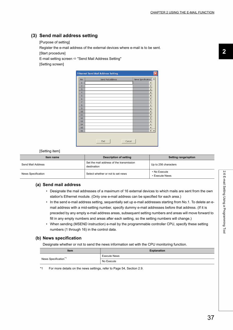
CHAPTER 2 USING THE E-MAIL FUNCTION
2
2.6
E-m
ail S
ettin
g U
sing
a P
rog
ram
min
g T
oo
l
(3) Send mail address setting[Purpose of setting]
Register the e-mail address of the external devices where e-mail is to be sent.
[Start procedure]
E-mail setting screen "Send Mail Address Setting"
[Setting screen]
[Setting item]
(a) Send mail address
• Designate the mail addresses of a maximum of 16 external devices to which mails are sent from the own
station's Ethernet module. (Only one e-mail address can be specified for each area.)
• In the send e-mail address setting, sequentially set up e-mail addresses starting from No.1. To delete an e-
mail address with a mid-setting number, specify dummy e-mail addresses before that address. (If it is
preceded by any empty e-mail address areas, subsequent setting numbers and areas will move forward to
fill in any empty numbers and areas after each setting, so the setting numbers will change.)
• When sending (MSEND instruction) e-mail by the programmable controller CPU, specify these setting
numbers (1 through 16) in the control data.
(b) News specification
Designate whether or not to send the news information set with the CPU monitoring function.
*1 For more details on the news settings, refer to Page 54, Section 2.9.
Item name Description of setting Setting range/option
Send Mail AddressSet the mail address of the transmission
destinationUp to 256 characters
News Specification Select whether or not to set news• No Execute
• Execute News
Item Explanation
News Specification*1Execute News
No Execute
37
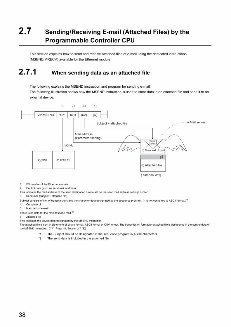
2.7 Sending/Receiving E-mail (Attached Files) by the Programmable Controller CPU
This section explains how to send and receive attached files of e-mail using the dedicated instructions
(MSEND/MRECV) available for the Ethernet module.
2.7.1 When sending data as an attached file
The following explains the MSEND instruction and program for sending e-mail.
The following illustration shows how the MSEND instruction is used to store data in an attached file and send it to an
external device.
*1 The Subject should be designated in the sequence program in ASCII characters.*2 The send data is included in the attached file.
1) I/O number of the Ethernet module
2) Control data (such as send mail address)
This indicates the mail address of the send destination device set on the send mail address settings screen.
3) Send mail (subject + attached file)
Subject consists of No. of transmissions and the character data designated by the sequence program. (It is not converted to ASCII format.)*1
4) Complete bit
5) Main text of e-mail
There is no data for the main text of e-mail.*2
6) Attached file
This indicates the device data designated by the MSEND instruction.
The attached file is sent in either one of binary format, ASCII format or CSV format. The transmission format for attached file is designated in the control data of
the MSEND instruction. ( Page 40, Section 2.7 (3))
(D)
QCPU QJ71E71
I/O No.
2) 3) 4)1)
(S2)(S1)"Un"ZP.MSEND
5)
6)
(.bin/.asc/.csv)
Mail address (Parameter setting)
Subject + attached file Mail server
Desti-nation
Main text of mail
Attached file
38
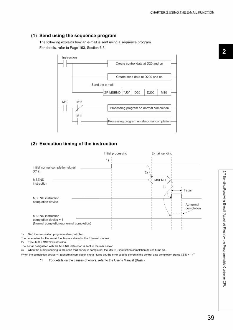
CHAPTER 2 USING THE E-MAIL FUNCTION
2
2.7
Se
nd
ing
/Re
ceivin
g E
-ma
il (Atta
che
d F
iles) b
y the
Pro
gra
mm
ab
le C
on
trolle
r CP
U
(1) Send using the sequence programThe following explains how an e-mail is sent using a sequence program.
For details, refer to Page 163, Section 6.3.
(2) Execution timing of the instruction
*1 For details on the causes of errors, refer to the User's Manual (Basic).
1) Start the own station programmable controller.
The parameters for the e-mail function are stored in the Ethernet module.
2) Execute the MSEND instruction.
The e-mail designated with the MSEND instruction is sent to the mail server.
3) When the e-mail sending to the send mail server is completed, the MSEND instruction completion device turns on.
When the completion device +1 (abnormal completion signal) turns on, the error code is stored in the control data completion status ((S1) + 1).*1
ZP.MSEND "U0" D20 D200 M10
M10 M11
M11
Instruction
Processing program on abnormal completion
Create control data at D20 and on
Create send data at D200 and on
Send the e-mail
Processing program on normal completion
1)
2)
3)
MSEND
Initial normal completion signal (X19)
MSEND instruction
MSEND instruction completion device
MSEND instruction completion device + 1 (Normal completion/abnormal completion)
Initial processing E-mail sending
Abnormal completion
1 scan
39
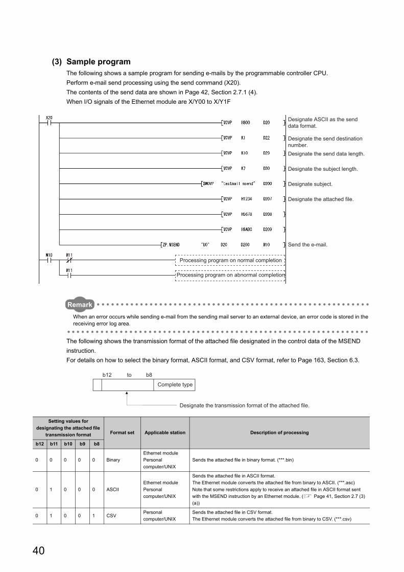
(3) Sample programThe following shows a sample program for sending e-mails by the programmable controller CPU.
Perform e-mail send processing using the send command (X20).
The contents of the send data are shown in Page 42, Section 2.7.1 (4).
When I/O signals of the Ethernet module are X/Y00 to X/Y1F
Remark
When an error occurs while sending e-mail from the sending mail server to an external device, an error code is stored in the receiving error log area.
The following shows the transmission format of the attached file designated in the control data of the MSEND
instruction.
For details on how to select the binary format, ASCII format, and CSV format, refer to Page 163, Section 6.3.
Setting values for
designating the attached file
transmission format Format set Applicable station Description of processing
b12 b11 b10 b9 b8
0 0 0 0 0 Binary
Ethernet module
Personal
computer/UNIX
Sends the attached file in binary format. (***.bin)
0 1 0 0 0 ASCII
Ethernet module
Personal
computer/UNIX
Sends the attached file in ASCII format.
The Ethernet module converts the attached file from binary to ASCII. (***.asc)
Note that some restrictions apply to receive an attached file in ASCII format sent
with the MSEND instruction by an Ethernet module. ( Page 41, Section 2.7 (3)
(a))
0 1 0 0 1 CSVPersonal
computer/UNIX
Sends the attached file in CSV format.
The Ethernet module converts the attached file from binary to CSV. (***.csv)
Processing program on normal completion
Processing program on abnormal completion
Designate ASCII as the send data format.
Designate the send destination number.Designate the send data length.
Designate the subject length.
Designate subject.
Designate the attached file.
Send the e-mail.
b12 b8
Complete type
Designate the transmission format of the attached file.
to
40
CHAPTER 2 USING THE E-MAIL FUNCTION
2
2.7
Se
nd
ing
/Re
ceivin
g E
-ma
il (Atta
che
d F
iles) b
y the
Pro
gra
mm
ab
le C
on
trolle
r CP
U
(a) Select binary format or ASCII format for communications between Ethernet
modules. To use ASCII format, set a data size (the size the MRECV instruction
receives) after conversion into ASCII within 6144 words. The attached file of the
MSEND instruction will be sent as is.
The name of the attached file is mmddhhss.bin (system date.bin).
mm: Month
dd: Date
hh: Hour
ss: minute
(b) Designate either binary format, ASCII format or CSV format when a PC/UNIX
receives e-mail sent from an Ethernet module. The attached file of the MSEND
instruction will be sent in the designated format.*1*2
• When binary format is designated
The name of the attached file is mmddhhss.bin (system date.bin).
mm: Month
dd: Date
hh: Hour
ss: minute
• When ASCII format is designated
The name of the attached file is mmddhhss.asc (system date.asc).
mm: Month
dd: Date
hh: Hour
ss: minute
• When CSV format is designated
The name of the attached file is mmddhhss.csv (system date.csv).
mm: Month
dd: Date
hh: Hour
ss: minute
*1 For details on how to receive e-mails, refer to Page 42, Section 2.7 (4).*2 The system date for the file name is the data managed by the programmable controller of the station in which the
Ethernet module is installed.
41
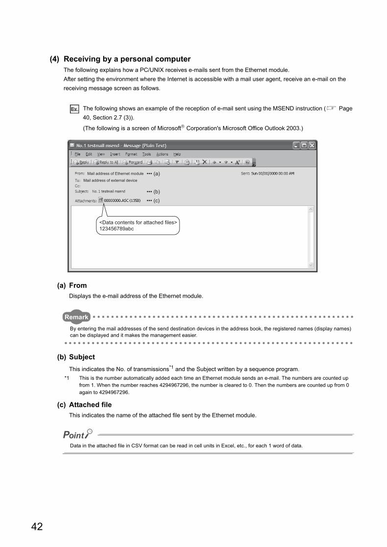
(4) Receiving by a personal computerThe following explains how a PC/UNIX receives e-mails sent from the Ethernet module.
After setting the environment where the Internet is accessible with a mail user agent, receive an e-mail on the
receiving message screen as follows.
The following shows an example of the reception of e-mail sent using the MSEND instruction ( Page
40, Section 2.7 (3)).
(The following is a screen of Microsoft Corporation's Microsoft Office Outlook 2003.)
(a) From
Displays the e-mail address of the Ethernet module.
Remark
By entering the mail addresses of the send destination devices in the address book, the registered names (display names) can be displayed and it makes the management easier.
(b) Subject
This indicates the No. of transmissions*1 and the Subject written by a sequence program.
*1 This is the number automatically added each time an Ethernet module sends an e-mail. The numbers are counted up from 1. When the number reaches 4294967296, the number is cleared to 0. Then the numbers are counted up from 0 again to 4294967296.
(c) Attached file
This indicates the name of the attached file sent by the Ethernet module.
Data in the attached file in CSV format can be read in cell units in Excel, etc., for each 1 word of data.
Mail address of Ethernet module
<Data contents for attached files>123456789abc
Mail address of external device••• (a)
••• (b)
••• (c)
42
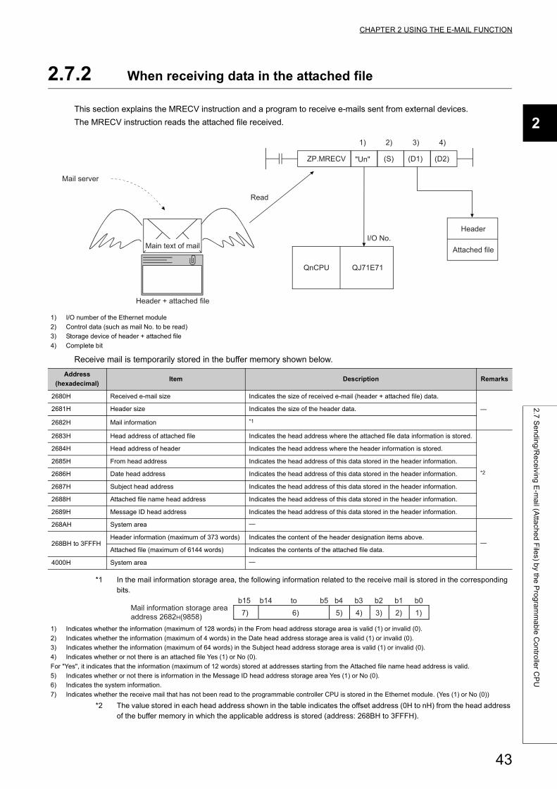
CHAPTER 2 USING THE E-MAIL FUNCTION
2
2.7
Se
nd
ing
/Re
ceivin
g E
-ma
il (Atta
che
d F
iles) b
y the
Pro
gra
mm
ab
le C
on
trolle
r CP
U
2.7.2 When receiving data in the attached file
This section explains the MRECV instruction and a program to receive e-mails sent from external devices.
The MRECV instruction reads the attached file received.
Receive mail is temporarily stored in the buffer memory shown below.
*1 In the mail information storage area, the following information related to the receive mail is stored in the corresponding bits.
*2 The value stored in each head address shown in the table indicates the offset address (0H to nH) from the head address of the buffer memory in which the applicable address is stored (address: 268BH to 3FFFH).
1) I/O number of the Ethernet module
2) Control data (such as mail No. to be read)
3) Storage device of header + attached file
4) Complete bit
Address
(hexadecimal)Item Description Remarks
2680H Received e-mail size Indicates the size of received e-mail (header + attached file) data.
2681H Header size Indicates the size of the header data.
2682H Mail information *1
2683H Head address of attached file Indicates the head address where the attached file data information is stored.
*2
2684H Head address of header Indicates the head address where the header information is stored.
2685H From head address Indicates the head address of this data stored in the header information.
2686H Date head address Indicates the head address of this data stored in the header information.
2687H Subject head address Indicates the head address of this data stored in the header information.
2688H Attached file name head address Indicates the head address of this data stored in the header information.
2689H Message ID head address Indicates the head address of this data stored in the header information.
268AH System area
268BH to 3FFFHHeader information (maximum of 373 words) Indicates the content of the header designation items above.
Attached file (maximum of 6144 words) Indicates the contents of the attached file data.
4000H System area
1) Indicates whether the information (maximum of 128 words) in the From head address storage area is valid (1) or invalid (0).
2) Indicates whether the information (maximum of 4 words) in the Date head address storage area is valid (1) or invalid (0).
3) Indicates whether the information (maximum of 64 words) in the Subject head address storage area is valid (1) or invalid (0).
4) Indicates whether or not there is an attached file Yes (1) or No (0).
For "Yes", it indicates that the information (maximum of 12 words) stored at addresses starting from the Attached file name head address is valid.
5) Indicates whether or not there is information in the Message ID head address storage area Yes (1) or No (0).
6) Indicates the system information.
7) Indicates whether the receive mail that has not been read to the programmable controller CPU is stored in the Ethernet module. (Yes (1) or No (0))
(D2)
QnCPU QJ71E71
I/O No.
2) 3) 4)1)
(D1)(S)"Un"ZP.MRECV
Attached file
Header
Read
Mail server
Header + attached file
Main text of mail
b15 b14 b5 b4 b3 b2 b1 b07) 6) 5) 4) 3) 2) 1)
Mail information storage area address 2682H(9858)
to
43
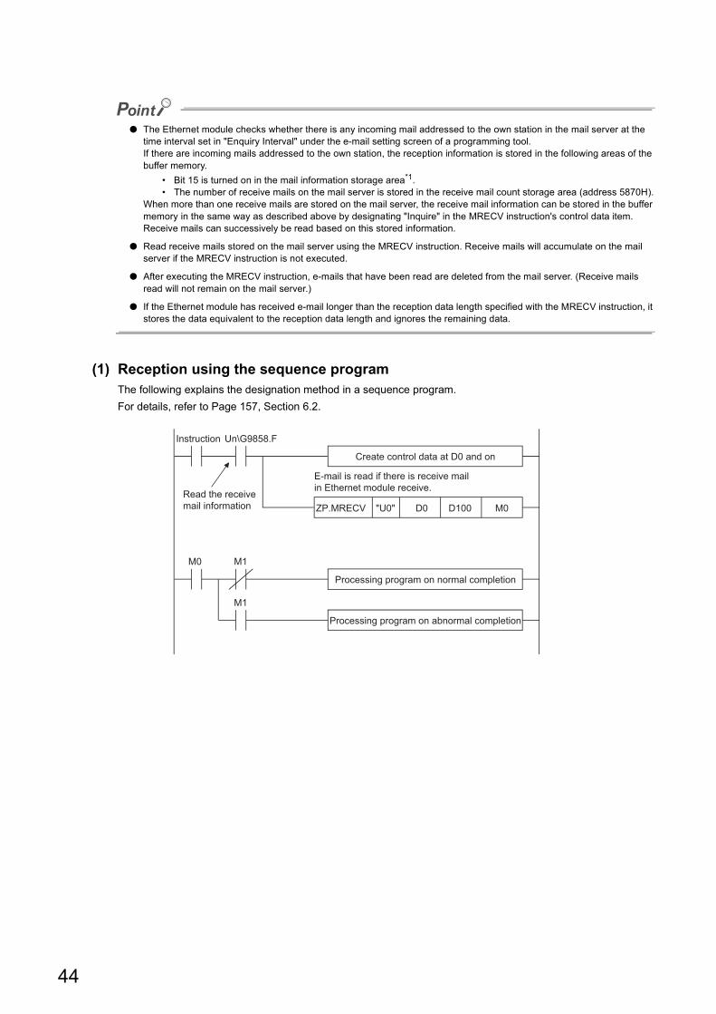
● The Ethernet module checks whether there is any incoming mail addressed to the own station in the mail server at the time interval set in "Enquiry Interval" under the e-mail setting screen of a programming tool.If there are incoming mails addressed to the own station, the reception information is stored in the following areas of the buffer memory.
• Bit 15 is turned on in the mail information storage area*1.• The number of receive mails on the mail server is stored in the receive mail count storage area (address 5870H).
When more than one receive mails are stored on the mail server, the receive mail information can be stored in the buffer memory in the same way as described above by designating "Inquire" in the MRECV instruction's control data item.Receive mails can successively be read based on this stored information.
● Read receive mails stored on the mail server using the MRECV instruction. Receive mails will accumulate on the mail server if the MRECV instruction is not executed.
● After executing the MRECV instruction, e-mails that have been read are deleted from the mail server. (Receive mails read will not remain on the mail server.)
● If the Ethernet module has received e-mail longer than the reception data length specified with the MRECV instruction, it stores the data equivalent to the reception data length and ignores the remaining data.
(1) Reception using the sequence programThe following explains the designation method in a sequence program.
For details, refer to Page 157, Section 6.2.
Instruction
Read the receive mail information
Processing program on normal completion
Processing program on abnormal completion
ZP.MRECV "U0" D0 D100 M0
M1
M1
Create control data at D0 and on
E-mail is read if there is receive mail in Ethernet module receive.
Un\G9858.F
M0
44
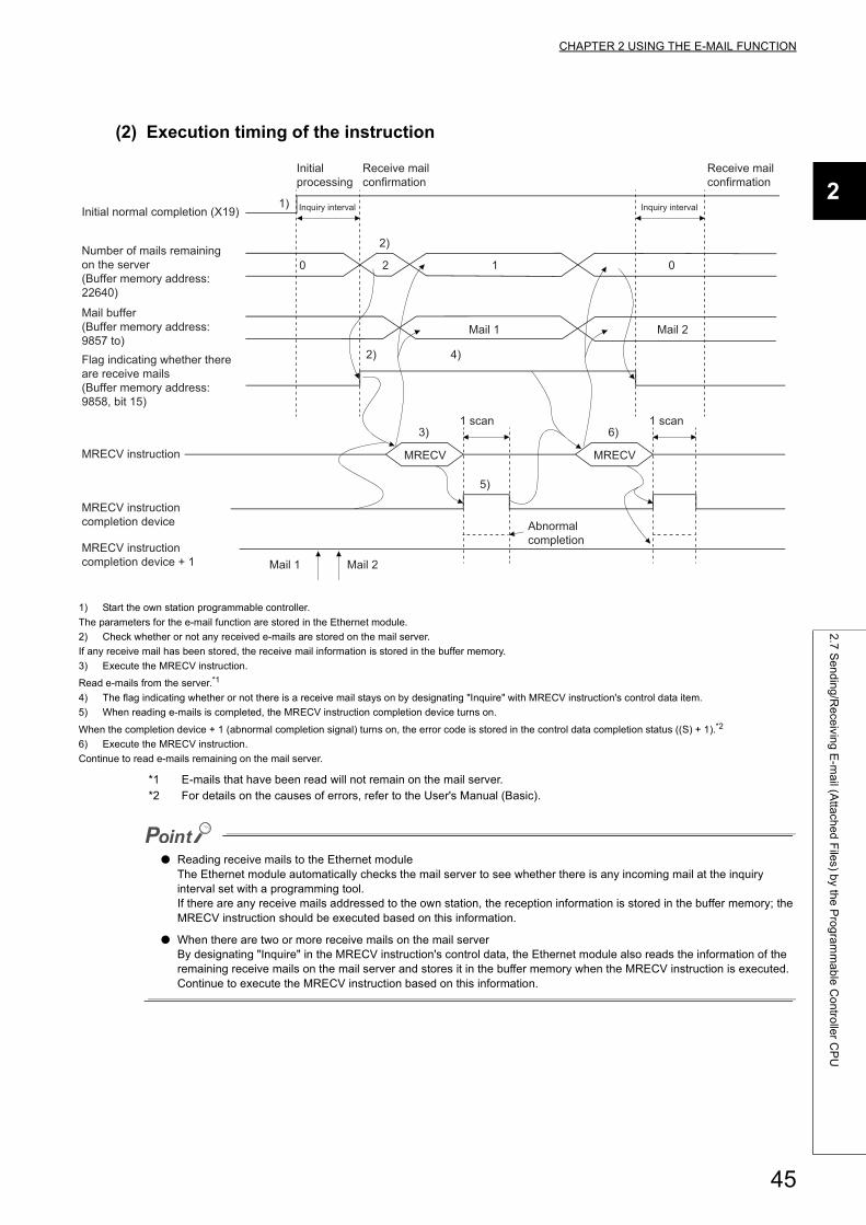
CHAPTER 2 USING THE E-MAIL FUNCTION
2
2.7
Se
nd
ing
/Re
ceivin
g E
-ma
il (Atta
che
d F
iles) b
y the
Pro
gra
mm
ab
le C
on
trolle
r CP
U
(2) Execution timing of the instruction
*1 E-mails that have been read will not remain on the mail server.*2 For details on the causes of errors, refer to the User's Manual (Basic).
● Reading receive mails to the Ethernet moduleThe Ethernet module automatically checks the mail server to see whether there is any incoming mail at the inquiry interval set with a programming tool.If there are any receive mails addressed to the own station, the reception information is stored in the buffer memory; the MRECV instruction should be executed based on this information.
● When there are two or more receive mails on the mail serverBy designating "Inquire" in the MRECV instruction's control data, the Ethernet module also reads the information of the remaining receive mails on the mail server and stores it in the buffer memory when the MRECV instruction is executed.Continue to execute the MRECV instruction based on this information.
1) Start the own station programmable controller.
The parameters for the e-mail function are stored in the Ethernet module.
2) Check whether or not any received e-mails are stored on the mail server.
If any receive mail has been stored, the receive mail information is stored in the buffer memory.
3) Execute the MRECV instruction.
Read e-mails from the server.*1
4) The flag indicating whether or not there is a receive mail stays on by designating "Inquire" with MRECV instruction's control data item.
5) When reading e-mails is completed, the MRECV instruction completion device turns on.
When the completion device + 1 (abnormal completion signal) turns on, the error code is stored in the control data completion status ((S) + 1).*2
6) Execute the MRECV instruction.
Continue to read e-mails remaining on the mail server.
0 012
1)
2)
2) 4)
3)
5)
6)
MRECV MRECV
Initial normal completion (X19)
Number of mails remaining on the server (Buffer memory address: 22640)
Mail buffer (Buffer memory address: 9857 to)Flag indicating whether there are receive mails(Buffer memory address: 9858, bit 15)
MRECV instruction
MRECV instruction completion device
MRECV instruction completion device + 1
Initial processing
Receive mail confirmation
Mail 1 Mail 2
Mail 1
Inquiry interval Inquiry interval
Receive mail confirmation
1 scan 1 scan
Abnormal completion
Mail 2
45
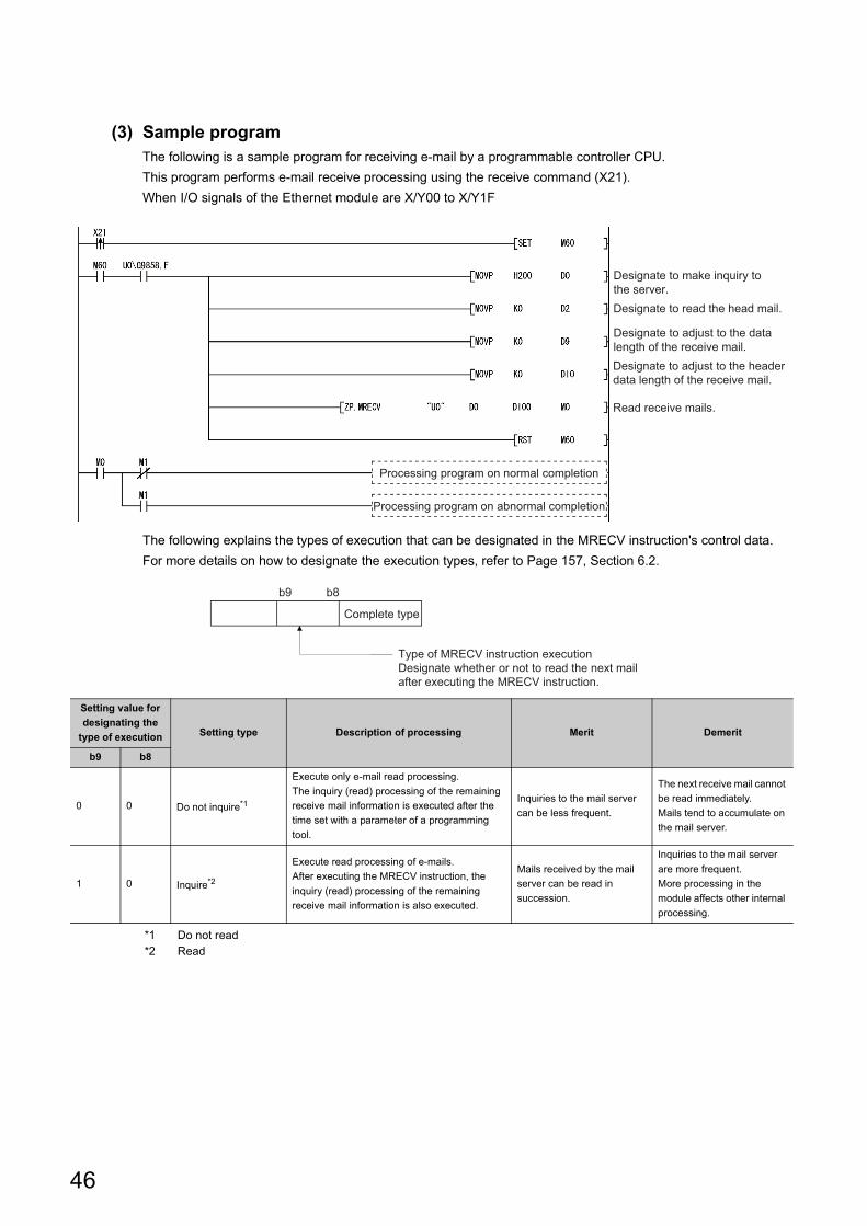
(3) Sample programThe following is a sample program for receiving e-mail by a programmable controller CPU.
This program performs e-mail receive processing using the receive command (X21).
When I/O signals of the Ethernet module are X/Y00 to X/Y1F
The following explains the types of execution that can be designated in the MRECV instruction's control data.
For more details on how to designate the execution types, refer to Page 157, Section 6.2.
*1 Do not read*2 Read
Setting value for
designating the
type of execution Setting type Description of processing Merit Demerit
b9 b8
0 0 Do not inquire*1
Execute only e-mail read processing.
The inquiry (read) processing of the remaining
receive mail information is executed after the
time set with a parameter of a programming
tool.
Inquiries to the mail server
can be less frequent.
The next receive mail cannot
be read immediately.
Mails tend to accumulate on
the mail server.
1 0 Inquire*2
Execute read processing of e-mails.
After executing the MRECV instruction, the
inquiry (read) processing of the remaining
receive mail information is also executed.
Mails received by the mail
server can be read in
succession.
Inquiries to the mail server
are more frequent.
More processing in the
module affects other internal
processing.
Designate to make inquiry to the server.Designate to read the head mail.
Designate to adjust to the data length of the receive mail.Designate to adjust to the header data length of the receive mail.
Read receive mails.
Processing program on normal completion
Processing program on abnormal completion
b9 b8
Type of MRECV instruction executionDesignate whether or not to read the next mail after executing the MRECV instruction.
Complete type
46
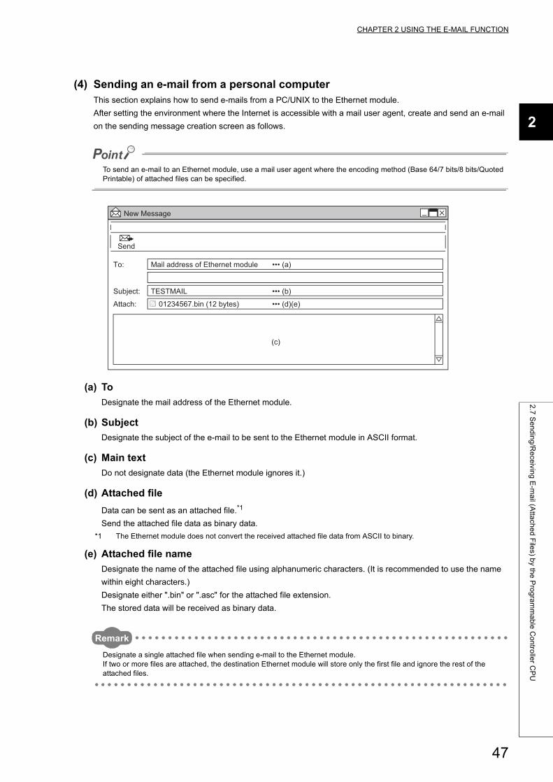
CHAPTER 2 USING THE E-MAIL FUNCTION
2
2.7
Se
nd
ing
/Re
ceivin
g E
-ma
il (Atta
che
d F
iles) b
y the
Pro
gra
mm
ab
le C
on
trolle
r CP
U
(4) Sending an e-mail from a personal computerThis section explains how to send e-mails from a PC/UNIX to the Ethernet module.
After setting the environment where the Internet is accessible with a mail user agent, create and send an e-mail
on the sending message creation screen as follows.
To send an e-mail to an Ethernet module, use a mail user agent where the encoding method (Base 64/7 bits/8 bits/Quoted Printable) of attached files can be specified.
(a) To
Designate the mail address of the Ethernet module.
(b) Subject
Designate the subject of the e-mail to be sent to the Ethernet module in ASCII format.
(c) Main text
Do not designate data (the Ethernet module ignores it.)
(d) Attached file
Data can be sent as an attached file.*1
Send the attached file data as binary data.
*1 The Ethernet module does not convert the received attached file data from ASCII to binary.
(e) Attached file name
Designate the name of the attached file using alphanumeric characters. (It is recommended to use the name
within eight characters.)
Designate either ".bin" or ".asc" for the attached file extension.
The stored data will be received as binary data.
Remark
Designate a single attached file when sending e-mail to the Ethernet module.If two or more files are attached, the destination Ethernet module will store only the first file and ignore the rest of the attached files.
TESTMAIL
Send
New Message
To:
Subject:
Attach:
Mail address of Ethernet module ••• (a)
01234567.bin (12 bytes)
••• (b)
••• (d)(e)
(c)
47
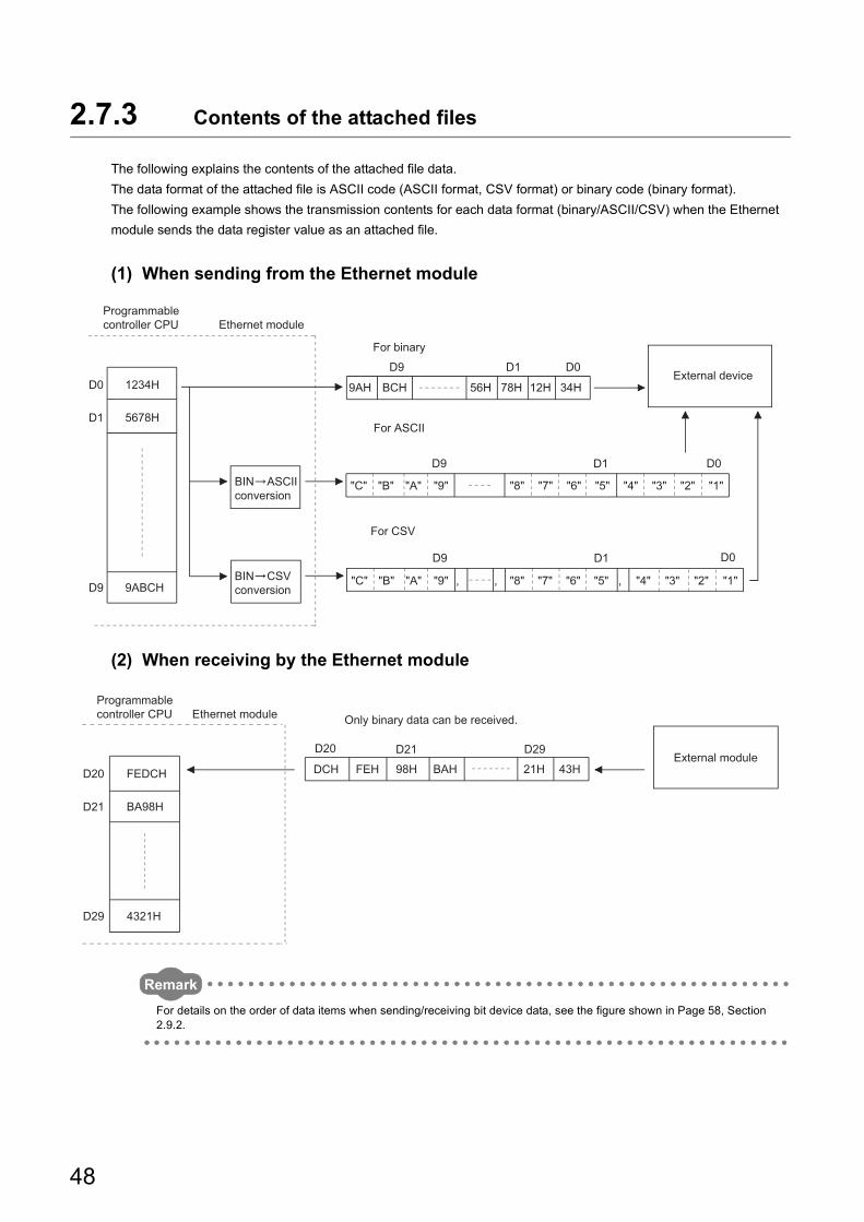
2.7.3 Contents of the attached files
The following explains the contents of the attached file data.
The data format of the attached file is ASCII code (ASCII format, CSV format) or binary code (binary format).
The following example shows the transmission contents for each data format (binary/ASCII/CSV) when the Ethernet
module sends the data register value as an attached file.
(1) When sending from the Ethernet module
(2) When receiving by the Ethernet module
Remark
For details on the order of data items when sending/receiving bit device data, see the figure shown in Page 58, Section 2.9.2.
D9 D1 D0
D9 D1 D0D0
D1
D9
1234H
5678H
9ABCH
9AH BCH 56H 78H 12H 34H
D9 D1 D0
"C" "B" "A" "9" "8" "7" "6" "5" "4" "3" "2" "1"
"1""2""3""4""5""6""7""8""9""A""B""C"
Ethernet module
BIN ASCII conversion
For ASCII
For binary
External device
Programmable controller CPU
BIN CSV conversion
For CSV
, , ,
D29D21D20
FEDCH
BA98H
4321H
D20
D21
D29
DCH FEH 98H BAH 21H 43H
Ethernet module
External module
Only binary data can be received.
Programmable controller CPU
48
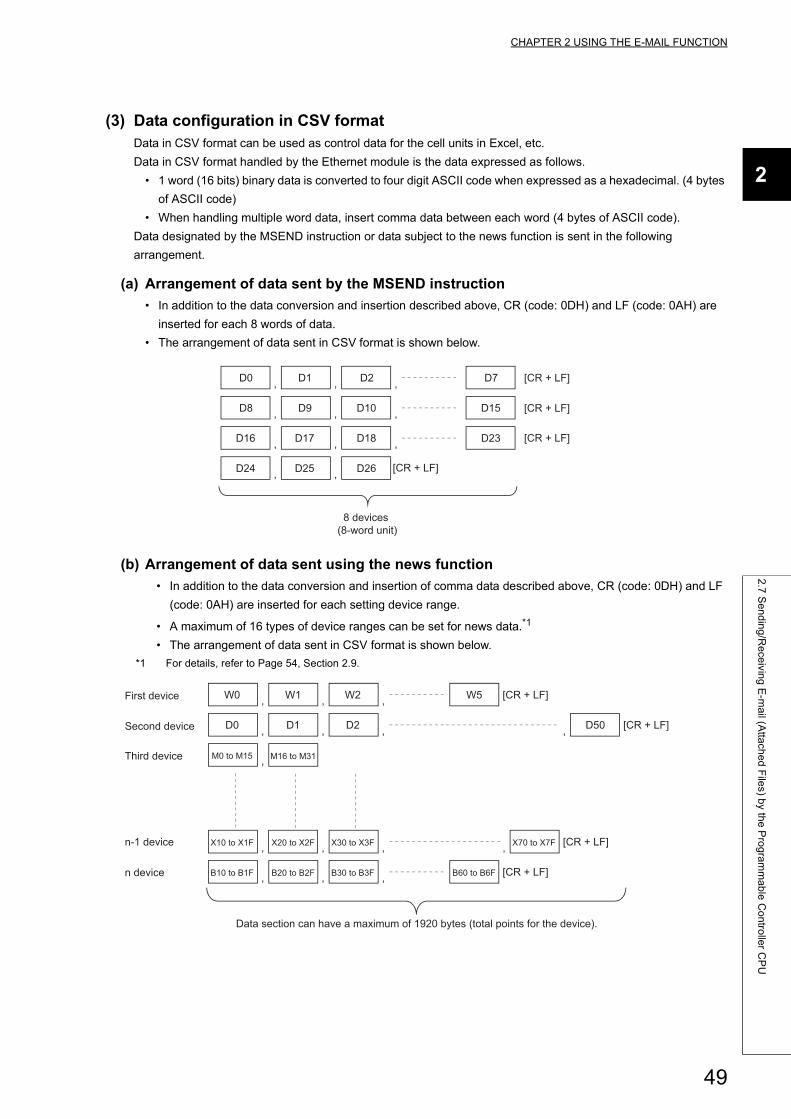
CHAPTER 2 USING THE E-MAIL FUNCTION
2
2.7
Se
nd
ing
/Re
ceivin
g E
-ma
il (Atta
che
d F
iles) b
y the
Pro
gra
mm
ab
le C
on
trolle
r CP
U
(3) Data configuration in CSV formatData in CSV format can be used as control data for the cell units in Excel, etc.
Data in CSV format handled by the Ethernet module is the data expressed as follows.
• 1 word (16 bits) binary data is converted to four digit ASCII code when expressed as a hexadecimal. (4 bytes
of ASCII code)
• When handling multiple word data, insert comma data between each word (4 bytes of ASCII code).
Data designated by the MSEND instruction or data subject to the news function is sent in the following
arrangement.
(a) Arrangement of data sent by the MSEND instruction
• In addition to the data conversion and insertion described above, CR (code: 0DH) and LF (code: 0AH) are
inserted for each 8 words of data.
• The arrangement of data sent in CSV format is shown below.
(b) Arrangement of data sent using the news function
• In addition to the data conversion and insertion of comma data described above, CR (code: 0DH) and LF
(code: 0AH) are inserted for each setting device range.
• A maximum of 16 types of device ranges can be set for news data.*1
• The arrangement of data sent in CSV format is shown below.
*1 For details, refer to Page 54, Section 2.9.
D8 D9 D10 D15
D16 D17 D18 D23
D24 D25 D26
D0 D1 D2 D7, , ,
, , ,
, , ,
, ,
[CR + LF]
[CR + LF]
8 devices (8-word unit)
[CR + LF]
[CR + LF]
D0 D1 D2 D50
W0 W1 W2 W5
X10 to X1F , X20 to X2F , X30 to X3F , [CR + LF], X70 to X7F
B10 to B1F , B20 to B2F , B30 to B3F , B60 to B6F [CR + LF]
Data section can have a maximum of 1920 bytes (total points for the device).
, , , [CR + LF],
, , , [CR + LF]First device
Second device
Third device
n-1 device
n device
M0 to M15 , M16 to M31
49
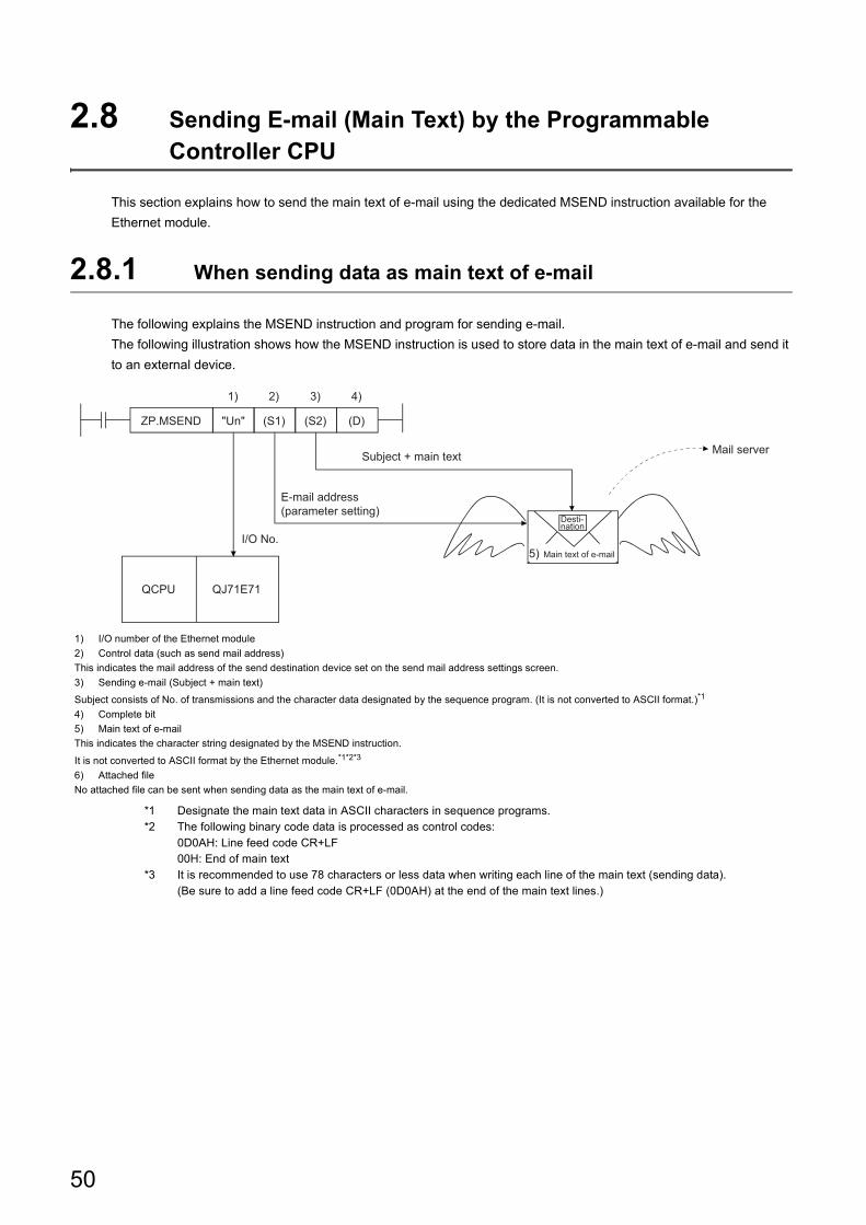
2.8 Sending E-mail (Main Text) by the Programmable Controller CPU
This section explains how to send the main text of e-mail using the dedicated MSEND instruction available for the
Ethernet module.
2.8.1 When sending data as main text of e-mail
The following explains the MSEND instruction and program for sending e-mail.
The following illustration shows how the MSEND instruction is used to store data in the main text of e-mail and send it
to an external device.
*1 Designate the main text data in ASCII characters in sequence programs.*2 The following binary code data is processed as control codes:
0D0AH: Line feed code CR+LF00H: End of main text
*3 It is recommended to use 78 characters or less data when writing each line of the main text (sending data).(Be sure to add a line feed code CR+LF (0D0AH) at the end of the main text lines.)
1) I/O number of the Ethernet module
2) Control data (such as send mail address)
This indicates the mail address of the send destination device set on the send mail address settings screen.
3) Sending e-mail (Subject + main text)
Subject consists of No. of transmissions and the character data designated by the sequence program. (It is not converted to ASCII format.)*1
4) Complete bit
5) Main text of e-mail
This indicates the character string designated by the MSEND instruction.
It is not converted to ASCII format by the Ethernet module.*1*2*3
6) Attached file
No attached file can be sent when sending data as the main text of e-mail.
(D)
QCPU QJ71E71
I/O No.
2) 3) 4)1)
(S2)(S1)"Un"ZP.MSEND
5)
E-mail address (parameter setting)
Subject + main text Mail server
Desti-nation
Main text of e-mail
50
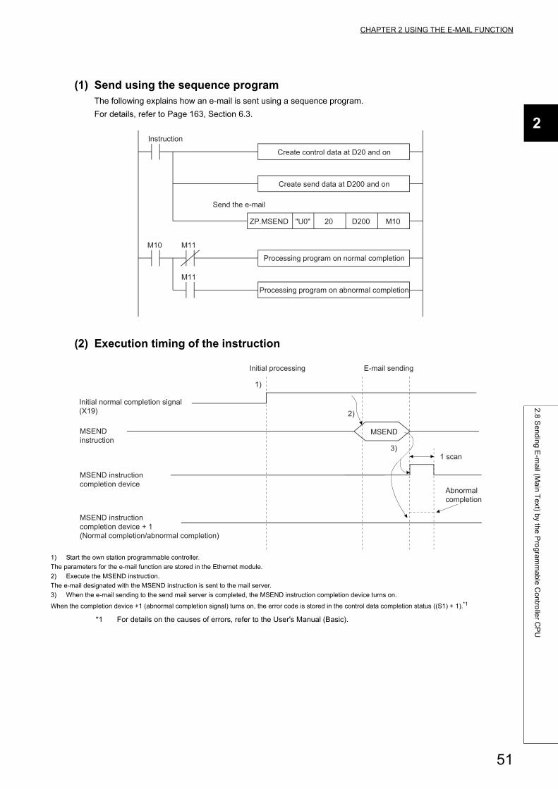
CHAPTER 2 USING THE E-MAIL FUNCTION
2
2.8
Se
nd
ing
E-m
ail (M
ain
Te
xt) by th
e P
rog
ram
ma
ble
Co
ntro
ller C
PU
(1) Send using the sequence programThe following explains how an e-mail is sent using a sequence program.
For details, refer to Page 163, Section 6.3.
(2) Execution timing of the instruction
*1 For details on the causes of errors, refer to the User's Manual (Basic).
1) Start the own station programmable controller.
The parameters for the e-mail function are stored in the Ethernet module.
2) Execute the MSEND instruction.
The e-mail designated with the MSEND instruction is sent to the mail server.
3) When the e-mail sending to the send mail server is completed, the MSEND instruction completion device turns on.
When the completion device +1 (abnormal completion signal) turns on, the error code is stored in the control data completion status ((S1) + 1).*1
ZP.MSEND "U0" 20 D200 M10
M11
M11M10
Send the e-mail
Instruction
Create control data at D20 and on
Create send data at D200 and on
Processing program on normal completion
Processing program on abnormal completion
1)
2)
3)
MSEND
Initial normal completion signal (X19)
MSEND instruction
MSEND instruction completion device
MSEND instruction completion device + 1 (Normal completion/abnormal completion)
Initial processing E-mail sending
Abnormal completion
1 scan
51
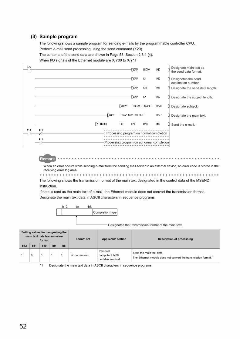
(3) Sample programThe following shows a sample program for sending e-mails by the programmable controller CPU.
Perform e-mail send processing using the send command (X20).
The contents of the send data are shown in Page 53, Section 2.8.1 (4).
When I/O signals of the Ethernet module are X/Y00 to X/Y1F
Remark
When an error occurs while sending e-mail from the sending mail server to an external device, an error code is stored in the receiving error log area.
The following shows the transmission format of the main text designated in the control data of the MSEND
instruction.
If data is sent as the main text of e-mail, the Ethernet module does not convert the transmission format.
Designate the main text data in ASCII characters in sequence programs.
*1 Designate the main text data in ASCII characters in sequence programs.
Setting values for designating the
main text data transmission
format Format set Applicable station Description of processing
b12 b11 b10 b9 b8
1 0 0 0 0 No conversion
Personal
computer/UNIX/
portable terminal
Send the main text data.
The Ethernet module does not convert the transmission format.*1
Designate main text as the send data format.
Designates the send destination number.Designate the send data length.
Designate the subject length.
Designate subject.
Send the e-mail.
Designate the main text.
Processing program on normal completion
Processing program on abnormal completion
b12 b8to
Completion type
Designates the transmission format of the main text.
52
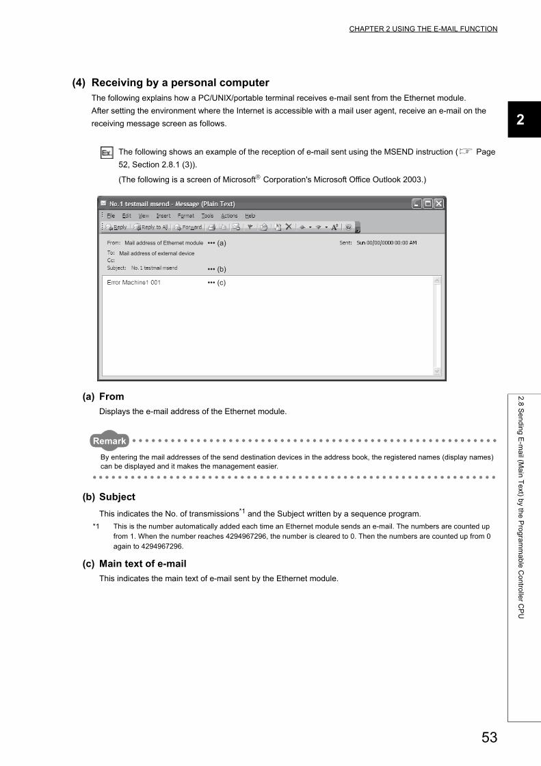
CHAPTER 2 USING THE E-MAIL FUNCTION
2
2.8
Se
nd
ing
E-m
ail (M
ain
Te
xt) by th
e P
rog
ram
ma
ble
Co
ntro
ller C
PU
(4) Receiving by a personal computerThe following explains how a PC/UNIX/portable terminal receives e-mail sent from the Ethernet module.
After setting the environment where the Internet is accessible with a mail user agent, receive an e-mail on the
receiving message screen as follows.
The following shows an example of the reception of e-mail sent using the MSEND instruction ( Page
52, Section 2.8.1 (3)).
(The following is a screen of Microsoft Corporation's Microsoft Office Outlook 2003.)
(a) From
Displays the e-mail address of the Ethernet module.
Remark
By entering the mail addresses of the send destination devices in the address book, the registered names (display names) can be displayed and it makes the management easier.
(b) Subject
This indicates the No. of transmissions*1 and the Subject written by a sequence program.
*1 This is the number automatically added each time an Ethernet module sends an e-mail. The numbers are counted up from 1. When the number reaches 4294967296, the number is cleared to 0. Then the numbers are counted up from 0 again to 4294967296.
(c) Main text of e-mail
This indicates the main text of e-mail sent by the Ethernet module.
Mail address of Ethernet module
Mail address of external device
••• (a)
••• (b)
••• (c)
53
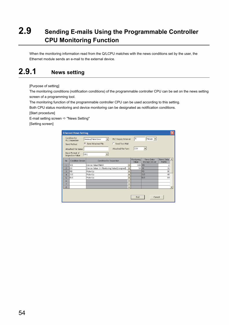
2.9 Sending E-mails Using the Programmable Controller CPU Monitoring Function
When the monitoring information read from the Q/LCPU matches with the news conditions set by the user, the
Ethernet module sends an e-mail to the external device.
2.9.1 News setting
[Purpose of setting]
The monitoring conditions (notification conditions) of the programmable controller CPU can be set on the news setting
screen of a programming tool.
The monitoring function of the programmable controller CPU can be used according to this setting.
Both CPU status monitoring and device monitoring can be designated as notification conditions.
[Start procedure]
E-mail setting screen "News Setting"
[Setting screen]
54
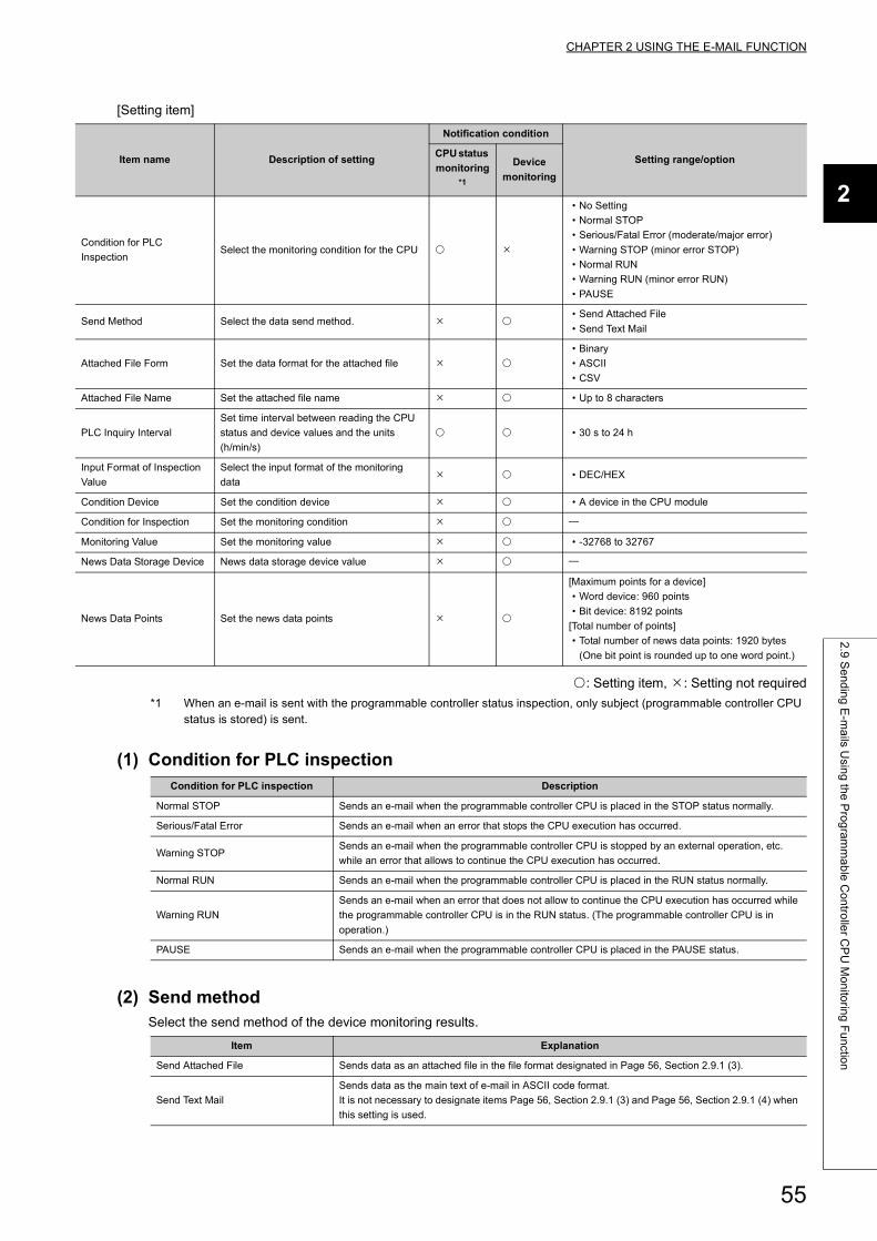
CHAPTER 2 USING THE E-MAIL FUNCTION
2
2.9
Se
nd
ing
E-m
ails U
sing
the
Pro
gra
mm
ab
le C
on
trolle
r CP
U M
on
itorin
g F
un
ction
[Setting item]
: Setting item, : Setting not required
*1 When an e-mail is sent with the programmable controller status inspection, only subject (programmable controller CPU status is stored) is sent.
(1) Condition for PLC inspection
(2) Send methodSelect the send method of the device monitoring results.
Item name Description of setting
Notification condition
Setting range/optionCPU status
monitoring*1
Device
monitoring
Condition for PLC
InspectionSelect the monitoring condition for the CPU
• No Setting
• Normal STOP
• Serious/Fatal Error (moderate/major error)
• Warning STOP (minor error STOP)
• Normal RUN
• Warning RUN (minor error RUN)
• PAUSE
Send Method Select the data send method. • Send Attached File
• Send Text Mail
Attached File Form Set the data format for the attached file
• Binary
• ASCII
• CSV
Attached File Name Set the attached file name • Up to 8 characters
PLC Inquiry Interval
Set time interval between reading the CPU
status and device values and the units
(h/min/s)
• 30 s to 24 h
Input Format of Inspection
Value
Select the input format of the monitoring
data • DEC/HEX
Condition Device Set the condition device • A device in the CPU module
Condition for Inspection Set the monitoring condition
Monitoring Value Set the monitoring value • -32768 to 32767
News Data Storage Device News data storage device value
News Data Points Set the news data points
[Maximum points for a device]
• Word device: 960 points
• Bit device: 8192 points
[Total number of points]
• Total number of news data points: 1920 bytes
(One bit point is rounded up to one word point.)
Condition for PLC inspection Description
Normal STOP Sends an e-mail when the programmable controller CPU is placed in the STOP status normally.
Serious/Fatal Error Sends an e-mail when an error that stops the CPU execution has occurred.
Warning STOPSends an e-mail when the programmable controller CPU is stopped by an external operation, etc.
while an error that allows to continue the CPU execution has occurred.
Normal RUN Sends an e-mail when the programmable controller CPU is placed in the RUN status normally.
Warning RUN
Sends an e-mail when an error that does not allow to continue the CPU execution has occurred while
the programmable controller CPU is in the RUN status. (The programmable controller CPU is in
operation.)
PAUSE Sends an e-mail when the programmable controller CPU is placed in the PAUSE status.
Item Explanation
Send Attached File Sends data as an attached file in the file format designated in Page 56, Section 2.9.1 (3).
Send Text Mail
Sends data as the main text of e-mail in ASCII code format.
It is not necessary to designate items Page 56, Section 2.9.1 (3) and Page 56, Section 2.9.1 (4) when
this setting is used.
55
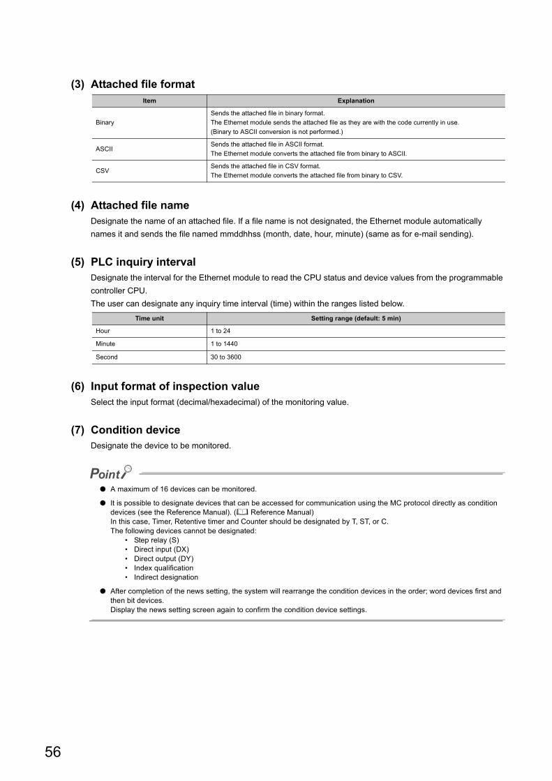
(3) Attached file format
(4) Attached file nameDesignate the name of an attached file. If a file name is not designated, the Ethernet module automatically
names it and sends the file named mmddhhss (month, date, hour, minute) (same as for e-mail sending).
(5) PLC inquiry intervalDesignate the interval for the Ethernet module to read the CPU status and device values from the programmable
controller CPU.
The user can designate any inquiry time interval (time) within the ranges listed below.
(6) Input format of inspection valueSelect the input format (decimal/hexadecimal) of the monitoring value.
(7) Condition deviceDesignate the device to be monitored.
● A maximum of 16 devices can be monitored.
● It is possible to designate devices that can be accessed for communication using the MC protocol directly as condition devices (see the Reference Manual). ( Reference Manual)In this case, Timer, Retentive timer and Counter should be designated by T, ST, or C.The following devices cannot be designated:
• Step relay (S)• Direct input (DX)• Direct output (DY)• Index qualification• Indirect designation
● After completion of the news setting, the system will rearrange the condition devices in the order; word devices first and then bit devices.Display the news setting screen again to confirm the condition device settings.
Item Explanation
Binary
Sends the attached file in binary format.
The Ethernet module sends the attached file as they are with the code currently in use.
(Binary to ASCII conversion is not performed.)
ASCIISends the attached file in ASCII format.
The Ethernet module converts the attached file from binary to ASCII.
CSVSends the attached file in CSV format.
The Ethernet module converts the attached file from binary to CSV.
Time unit Setting range (default: 5 min)
Hour 1 to 24
Minute 1 to 1440
Second 30 to 3600
56
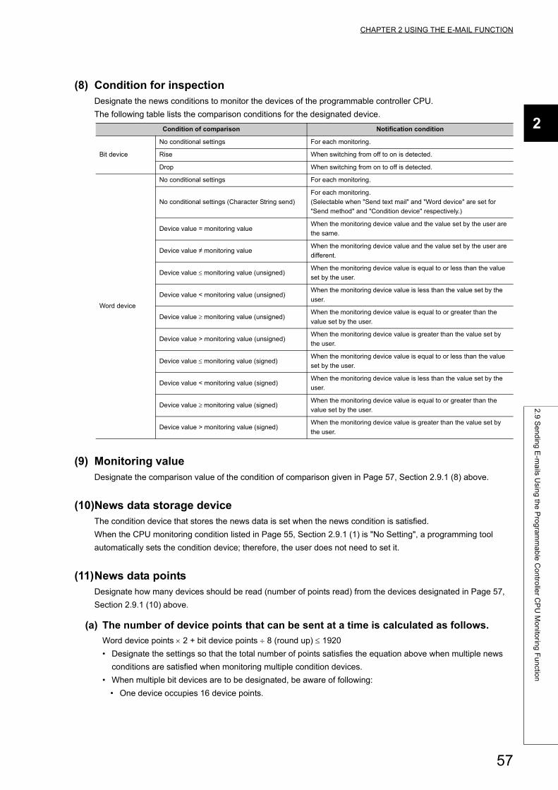
CHAPTER 2 USING THE E-MAIL FUNCTION
2
2.9
Se
nd
ing
E-m
ails U
sing
the
Pro
gra
mm
ab
le C
on
trolle
r CP
U M
on
itorin
g F
un
ction
(8) Condition for inspectionDesignate the news conditions to monitor the devices of the programmable controller CPU.
The following table lists the comparison conditions for the designated device.
(9) Monitoring valueDesignate the comparison value of the condition of comparison given in Page 57, Section 2.9.1 (8) above.
(10)News data storage deviceThe condition device that stores the news data is set when the news condition is satisfied.
When the CPU monitoring condition listed in Page 55, Section 2.9.1 (1) is "No Setting", a programming tool
automatically sets the condition device; therefore, the user does not need to set it.
(11)News data pointsDesignate how many devices should be read (number of points read) from the devices designated in Page 57,
Section 2.9.1 (10) above.
(a) The number of device points that can be sent at a time is calculated as follows.
Word device points 2 + bit device points 8 (round up) 1920
• Designate the settings so that the total number of points satisfies the equation above when multiple news
conditions are satisfied when monitoring multiple condition devices.
• When multiple bit devices are to be designated, be aware of following:
• One device occupies 16 device points.
Condition of comparison Notification condition
Bit device
No conditional settings For each monitoring.
Rise When switching from off to on is detected.
Drop When switching from on to off is detected.
Word device
No conditional settings For each monitoring.
No conditional settings (Character String send)
For each monitoring.
(Selectable when "Send text mail" and "Word device" are set for
"Send method" and "Condition device" respectively.)
Device value = monitoring valueWhen the monitoring device value and the value set by the user are
the same.
Device value monitoring valueWhen the monitoring device value and the value set by the user are
different.
Device value monitoring value (unsigned)When the monitoring device value is equal to or less than the value
set by the user.
Device value < monitoring value (unsigned)When the monitoring device value is less than the value set by the
user.
Device value monitoring value (unsigned)When the monitoring device value is equal to or greater than the
value set by the user.
Device value > monitoring value (unsigned)When the monitoring device value is greater than the value set by
the user.
Device value monitoring value (signed)When the monitoring device value is equal to or less than the value
set by the user.
Device value < monitoring value (signed)When the monitoring device value is less than the value set by the
user.
Device value monitoring value (signed)When the monitoring device value is equal to or greater than the
value set by the user.
Device value > monitoring value (signed)When the monitoring device value is greater than the value set by
the user.
57
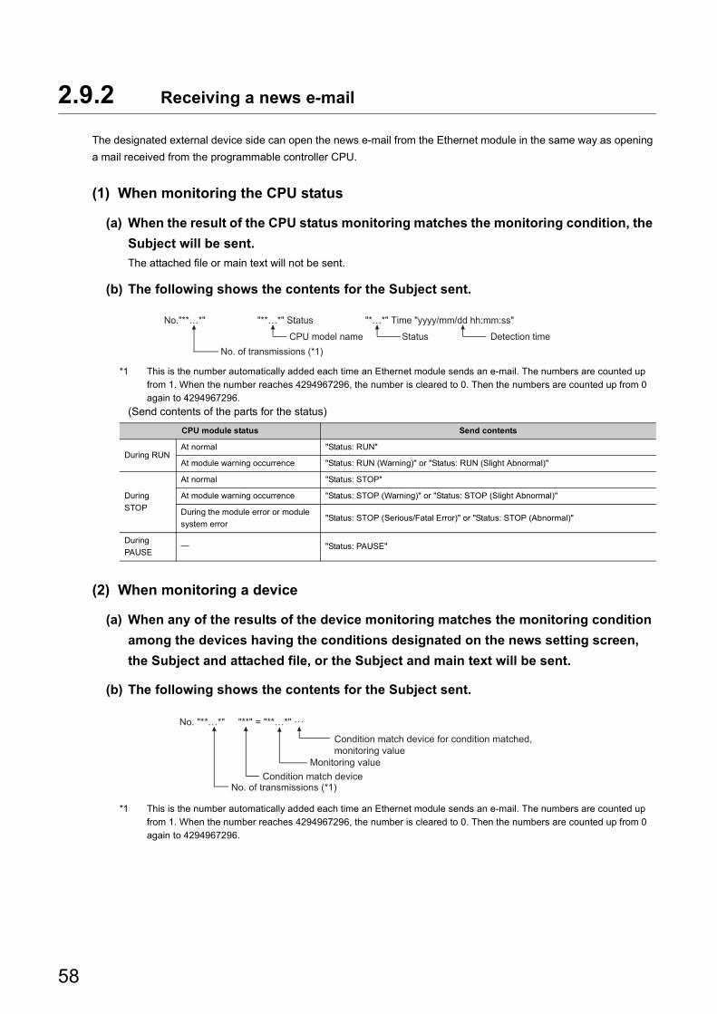
2.9.2 Receiving a news e-mail
The designated external device side can open the news e-mail from the Ethernet module in the same way as opening
a mail received from the programmable controller CPU.
(1) When monitoring the CPU status
(a) When the result of the CPU status monitoring matches the monitoring condition, the
Subject will be sent.
The attached file or main text will not be sent.
(b) The following shows the contents for the Subject sent.
*1 This is the number automatically added each time an Ethernet module sends an e-mail. The numbers are counted up from 1. When the number reaches 4294967296, the number is cleared to 0. Then the numbers are counted up from 0 again to 4294967296.
(Send contents of the parts for the status)
(2) When monitoring a device
(a) When any of the results of the device monitoring matches the monitoring condition
among the devices having the conditions designated on the news setting screen,
the Subject and attached file, or the Subject and main text will be sent.
(b) The following shows the contents for the Subject sent.
*1 This is the number automatically added each time an Ethernet module sends an e-mail. The numbers are counted up from 1. When the number reaches 4294967296, the number is cleared to 0. Then the numbers are counted up from 0 again to 4294967296.
CPU module status Send contents
During RUNAt normal "Status: RUN"
At module warning occurrence "Status: RUN (Warning)" or "Status: RUN (Slight Abnormal)"
During
STOP
At normal "Status: STOP"
At module warning occurrence "Status: STOP (Warning)" or "Status: STOP (Slight Abnormal)"
During the module error or module
system error"Status: STOP (Serious/Fatal Error)" or "Status: STOP (Abnormal)"
During
PAUSE "Status: PAUSE"
No. of transmissions (*1)
No."**…*" "**…*" Status "*…*" Time "yyyy/mm/dd hh:mm:ss"
CPU model name Status Detection time
No. of transmissions (*1)
No. "**…*" "**" = "**…*" ···
Condition match deviceMonitoring value
Condition match device for condition matched, monitoring value
58
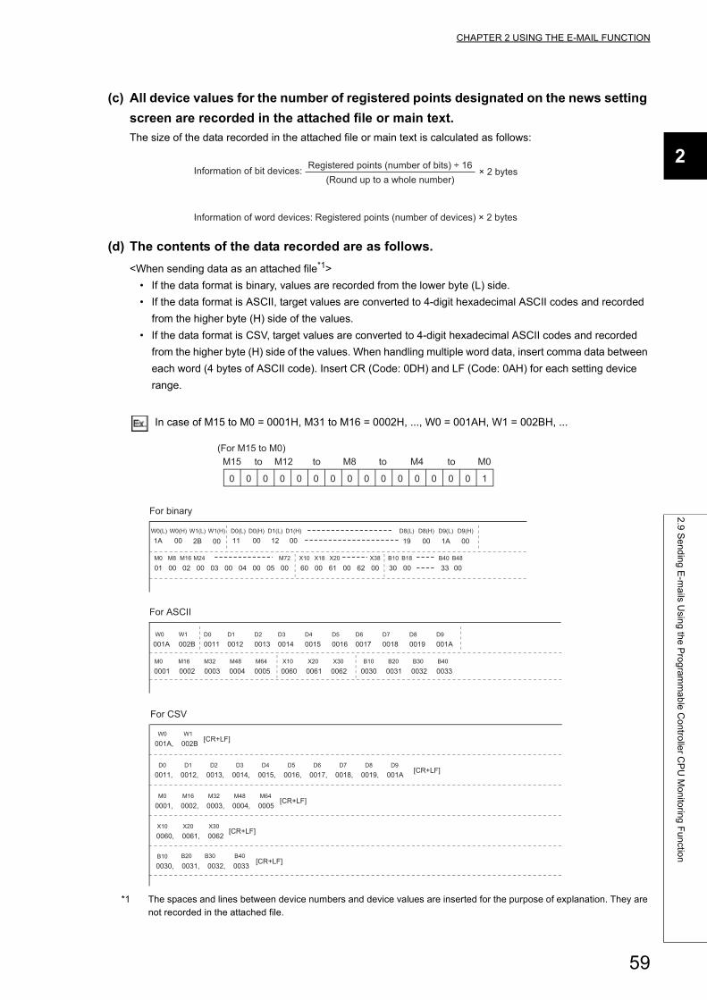
CHAPTER 2 USING THE E-MAIL FUNCTION
2
2.9
Se
nd
ing
E-m
ails U
sing
the
Pro
gra
mm
ab
le C
on
trolle
r CP
U M
on
itorin
g F
un
ction
(c) All device values for the number of registered points designated on the news setting
screen are recorded in the attached file or main text.
The size of the data recorded in the attached file or main text is calculated as follows:
(d) The contents of the data recorded are as follows.
<When sending data as an attached file*1>
• If the data format is binary, values are recorded from the lower byte (L) side.
• If the data format is ASCII, target values are converted to 4-digit hexadecimal ASCII codes and recorded
from the higher byte (H) side of the values.
• If the data format is CSV, target values are converted to 4-digit hexadecimal ASCII codes and recorded
from the higher byte (H) side of the values. When handling multiple word data, insert comma data between
each word (4 bytes of ASCII code). Insert CR (Code: 0DH) and LF (Code: 0AH) for each setting device
range.
In case of M15 to M0 = 0001H, M31 to M16 = 0002H, ..., W0 = 001AH, W1 = 002BH, ...
*1 The spaces and lines between device numbers and device values are inserted for the purpose of explanation. They are not recorded in the attached file.
Information of bit devices: Registered points (number of bits) ÷ 16(Round up to a whole number)
× 2 bytes
Information of word devices: Registered points (number of devices) × 2 bytes
0 0 0 0 0 0 0 0 0 0 0 0 0 0
M15 M8M12 M4
0 1
M0(For M15 to M0)
to to to to
0001 0002 0003 0004 0005M16M0 M32 M48 M64
0060 0061 0062X10 X20 X30
001AW0
002BW1
0031 00320030B10 B20 B30
0033B40
0011 0012 0013 0014 0015 0016 0017 0018 0019 001AD1D0 D2 D3 D4 D5 D6 D7 D8 D9
60 61 62X10 X18 X20 X38
01 00 02 00 00 00 00 0000 0003 04 05M8M0 M16 M24 M72
30 00B10 B18 B40
33 00B48
19 00 1A 0011 00D0(L) D0(H) D1(L) D1(H)
12 00D9(L) D9(H)D8(L) D8(H)
2BW0(L) W0(H)
1A 00W1(L) W1(H)
0001, 0002, 0003, 0004, 0005M16M0 M32 M48 M64
[CR+LF]
0060, 0061, 0062X10 X20 X30
[CR+LF]
001A, 002BW0 W1
[CR+LF]
0030, 0031, 0032, 0033B10 B20 B30 B40
[CR+LF]
0011, 0012, 0013, 0014, 0015, 0016, 0017, 0018, 0019, 001AD1D0 D2 D3 D4 D5 D6 D7 D8 D9
[CR+LF]
00
For ASCII
For binary
For CSV
59
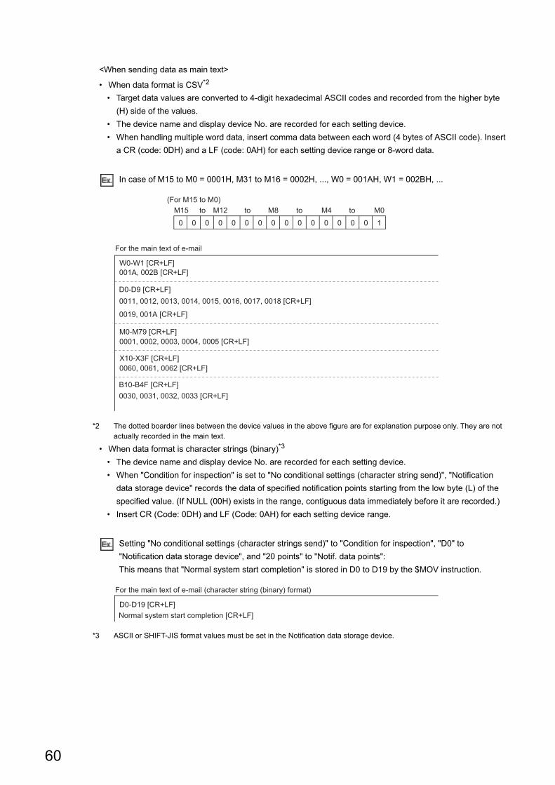
<When sending data as main text>
• When data format is CSV*2
• Target data values are converted to 4-digit hexadecimal ASCII codes and recorded from the higher byte
(H) side of the values.
• The device name and display device No. are recorded for each setting device.
• When handling multiple word data, insert comma data between each word (4 bytes of ASCII code). Insert
a CR (code: 0DH) and a LF (code: 0AH) for each setting device range or 8-word data.
In case of M15 to M0 = 0001H, M31 to M16 = 0002H, ..., W0 = 001AH, W1 = 002BH, ...
*2 The dotted boarder lines between the device values in the above figure are for explanation purpose only. They are not actually recorded in the main text.
• When data format is character strings (binary)*3
• The device name and display device No. are recorded for each setting device.
• When "Condition for inspection" is set to "No conditional settings (character string send)", "Notification
data storage device" records the data of specified notification points starting from the low byte (L) of the
specified value. (If NULL (00H) exists in the range, contiguous data immediately before it are recorded.)
• Insert CR (Code: 0DH) and LF (Code: 0AH) for each setting device range.
Setting "No conditional settings (character strings send)" to "Condition for inspection", "D0" to
"Notification data storage device", and "20 points" to "Notif. data points":
This means that "Normal system start completion" is stored in D0 to D19 by the $MOV instruction.
*3 ASCII or SHIFT-JIS format values must be set in the Notification data storage device.
0 0 0 0 0 0 0 0 0 0 0 0 0 0
M15 M8M12 M4
0 1
M0(For M15 to M0)
to to to to
0001, 0002, 0003, 0004, 0005 [CR+LF]M0-M79 [CR+LF]
0060, 0061, 0062 [CR+LF]X10-X3F [CR+LF]
001A, 002B [CR+LF]W0-W1 [CR+LF]
0030, 0031, 0032, 0033 [CR+LF]B10-B4F [CR+LF]
0011, 0012, 0013, 0014, 0015, 0016, 0017, 0018 [CR+LF]
0019, 001A [CR+LF]
D0-D9 [CR+LF]
For the main text of e-mail
Normal system start completion [CR+LF]D0-D19 [CR+LF]
For the main text of e-mail (character string (binary) format)
60

CHAPTER 2 USING THE E-MAIL FUNCTION
2
2.9
Se
nd
ing
E-m
ails U
sing
the
Pro
gra
mm
ab
le C
on
trolle
r CP
U M
on
itorin
g F
un
ction
● When e-mail is sent after the result of the device monitoring and the monitoring condition match, the Subject and attached file, or the Subject and main text will be sent.As a device monitoring result, the data that was read from the programmable controller CPU by the Ethernet module in order to determine whether or not the conditions match will be sent.For details on the correspondence between the word device values and the data format of the attached file, see the figure in Page 48, Section 2.7.3.The main text will be sent after converting the data read into ASCII code data.If the condition for inspection is set to "No conditional settings (character strings send)" for e-mail text transmission, however, binary code data are sent without being converted.
● When e-mail is sent after the result of the CPU status monitoring and the monitoring condition match, only the Subject will be sent. The attached file and main text will not be sent.
● Mail contents are not properly displayed on the receiving side when both of the following conditions are met:- the format of data notified in the main text is in binary (character string)- the value set in the news data storage device is in a format other than ASCII format or SHIFT-JIS format
61
CHAPTER 3 COMMUNICATIONS VIA OTHER
NETWORKS
An Ethernet module can access other stations from an external device or a Q/LCPU in a station where an Ethernet
module is connected via Ethernet and the following networks:
• CC-Link IE Controller Network
• CC-Link IE Field Network
• MELSECNET/H
• MELSECNET/10
This chapter describes the CC-Link IE Controller Network, CC-Link IE Field Network, MELSECNET/H,
MELSECNET/10 relay communication function to communicate data with other stations via an Ethernet module and
network modules.
3.1 CC-Link IE Controller Network, CC-Link IE Field Network, MELSECNET/H, MELSECNET/10 Relay Communication Function
By setting the parameter described in Page 66, Section 3.3, the other station access becomes possible with the CC-
Link IE Controller Network, CC-Link IE Field Network, MELSECNET/H, MELSECNET/10 relay communication
function.
Function that can be used for
communication
Communication range Communication
request sourceReference
When using this function When not using this function
Communication using the MC
protocol
Possible to read/write data from/to
another station's programmable
controller, which is the access request
destination, from an access source
device via multiple networks and Ethernet
Only possible to read/write data from/to
the programmable controllers of other
stations in Ethernet where a station with
an Ethernet module is connected
(Example)
Only the access 1) shown in the figure in
Page 63, Section 3.2.1 is accessible.
External deviceReference
manual
Communication using the data
link instructions
CPU in a station
where a network
module is
connected
Page 84,
CHAPTER 4
Communication with other
stations using a programming
tool
Programming
tool
Operating
manual for the
programming
tool used
62
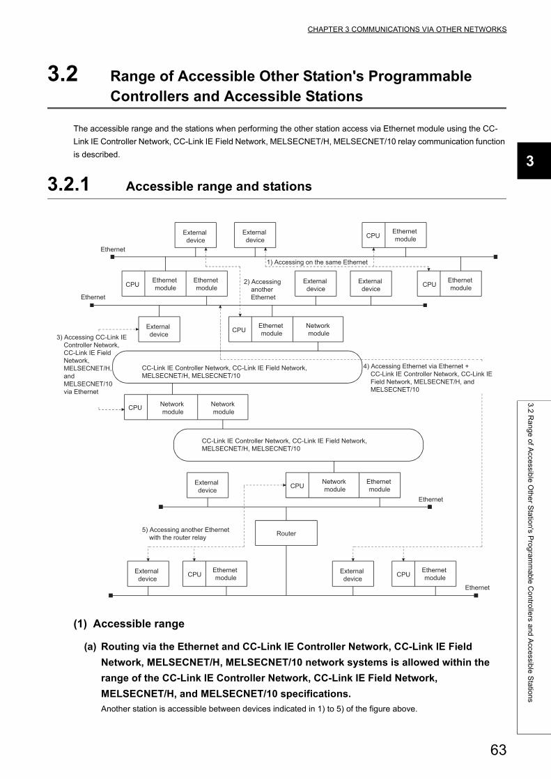
CHAPTER 3 COMMUNICATIONS VIA OTHER NETWORKS
3
3.2
Ra
ng
e o
f Acce
ssible
Oth
er S
tatio
n's P
rog
ram
ma
ble
Co
ntro
llers a
nd
Acce
ssible
Sta
tion
s
3.2 Range of Accessible Other Station's Programmable Controllers and Accessible Stations
The accessible range and the stations when performing the other station access via Ethernet module using the CC-
Link IE Controller Network, CC-Link IE Field Network, MELSECNET/H, MELSECNET/10 relay communication function
is described.
3.2.1 Accessible range and stations
(1) Accessible range
(a) Routing via the Ethernet and CC-Link IE Controller Network, CC-Link IE Field
Network, MELSECNET/H, MELSECNET/10 network systems is allowed within the
range of the CC-Link IE Controller Network, CC-Link IE Field Network,
MELSECNET/H, and MELSECNET/10 specifications.
Another station is accessible between devices indicated in 1) to 5) of the figure above.
Ethernet
CPU
CPU
Ethernet
CPU
CPU
CC-Link IE Controller Network, CC-Link IE Field Network, MELSECNET/H, MELSECNET/10
CPU
CC-Link IE Controller Network, CC-Link IE Field Network, MELSECNET/H, MELSECNET/10
CPU
Router
Ethernet
Ethernet
CPUCPU
3) Accessing CC-Link IE Controller Network, CC-Link IE Field Network, MELSECNET/H, and MELSECNET/10 via Ethernet
4) Accessing Ethernet via Ethernet + CC-Link IE Controller Network, CC-Link IE Field Network, MELSECNET/H, and MELSECNET/10
External device
External device
1) Accessing on the same Ethernet
Ethernet module
Ethernet module
Ethernet module
2) Accessing another Ethernet
External device
External device
Ethernet module
External device
Ethernet module
Network module
Network module
Network module
External device
Network module
Ethernet module
5) Accessing another Ethernet with the router relay
External device
Ethernet module
External device
Ethernet module
63
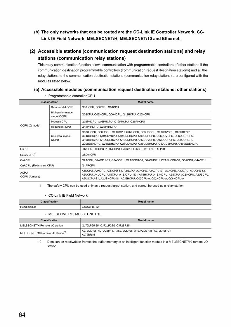
(b) The only networks that can be routed are the CC-Link IE Controller Network, CC-
Link IE Field Network, MELSECNET/H, MELSECNET/10 and Ethernet.
(2) Accessible stations (communication request destination stations) and relay
stations (communication relay stations)This relay communication function allows communication with programmable controllers of other stations if the
communication destination programmable controllers (communication request destination stations) and all the
relay stations to the communication destination stations (communication relay stations) are configured with the
modules listed below.
(a) Accessible modules (communication request destination stations: other stations)
• Programmable controller CPU
*1 The safety CPU can be used only as a request target station, and cannot be used as a relay station.
• CC-Link IE Field Network
• MELSECNET/H, MELSECNET/10
*2 Data can be read/written from/to the buffer memory of an intelligent function module in a MELSECNET/10 remote I/O station.
Classification Model name
QCPU (Q mode)
Basic model QCPU Q00JCPU, Q00CPU, Q01CPU
High performance
model QCPUQ02CPU, Q02HCPU, Q06HCPU, Q12HCPU, Q25HCPU
Process CPU Q02PHCPU, Q06PHCPU, Q12PHCPU, Q25PHCPU
Redundant CPU Q12PRHCPU, Q25PRHCPU
Universal model
QCPU
Q00UJCPU, Q00UCPU, Q01UCPU, Q02UCPU, Q03UDCPU, Q03UDVCPU, Q03UDECPU,
Q04UDHCPU, Q04UDVCPU, Q04UDEHCPU, Q06UDHCPU, Q06UDVCPU, Q06UDEHCPU,
Q10UDHCPU, Q10UDEHCPU, Q13UDHCPU, Q13UDVCPU, Q13UDEHCPU, Q20UDHCPU,
Q20UDEHCPU, Q26UDHCPU, Q26UDVCPU, Q26UDEHCPU, Q50UDEHCPU, Q100UDEHCPU
LCPU L02CPU, L02CPU-P, L02SCPU, L26CPU, L26CPU-BT, L26CPU-PBT
Safety CPU*1 QS001CPU
QnACPU Q2ACPU, Q2ACPU-S1, Q2ASCPU, Q2ASCPU-S1, Q2ASHCPU, Q2ASHCPU-S1, Q3ACPU, Q4ACPU
QnACPU (Redundant CPU) Q4ARCPU
ACPU
QCPU (A mode)
A1NCPU, A2NCPU, A2NCPU-S1, A3NCPU, A2ACPU, A2ACPU-S1, A3ACPU, A2UCPU, A2UCPU-S1,
A3UCPU, A4UCPU, A1SCPU, A1SJCPU(-S3), A1SHCPU, A1SJHCPU, A2SCPU, A2SHCPU, A2USCPU,
A2USCPU-S1, A2USHCPU-S1, A0J2HCPU, Q02CPU-A, Q02HCPU-A, Q06HCPU-A
Classification Model name
Head module LJ72GF15-T2
Classification Model name
MELSECNET/H Remote I/O station QJ72LP25-25, QJ72LP25G, QJ72BR15
MELSECNET/10 Remote I/O station*2AJ72QLP25, AJ72QBR15, A1SJ72QLP25, A1SJ72QBR15, AJ72LP25(G)
AJ72BR15
64
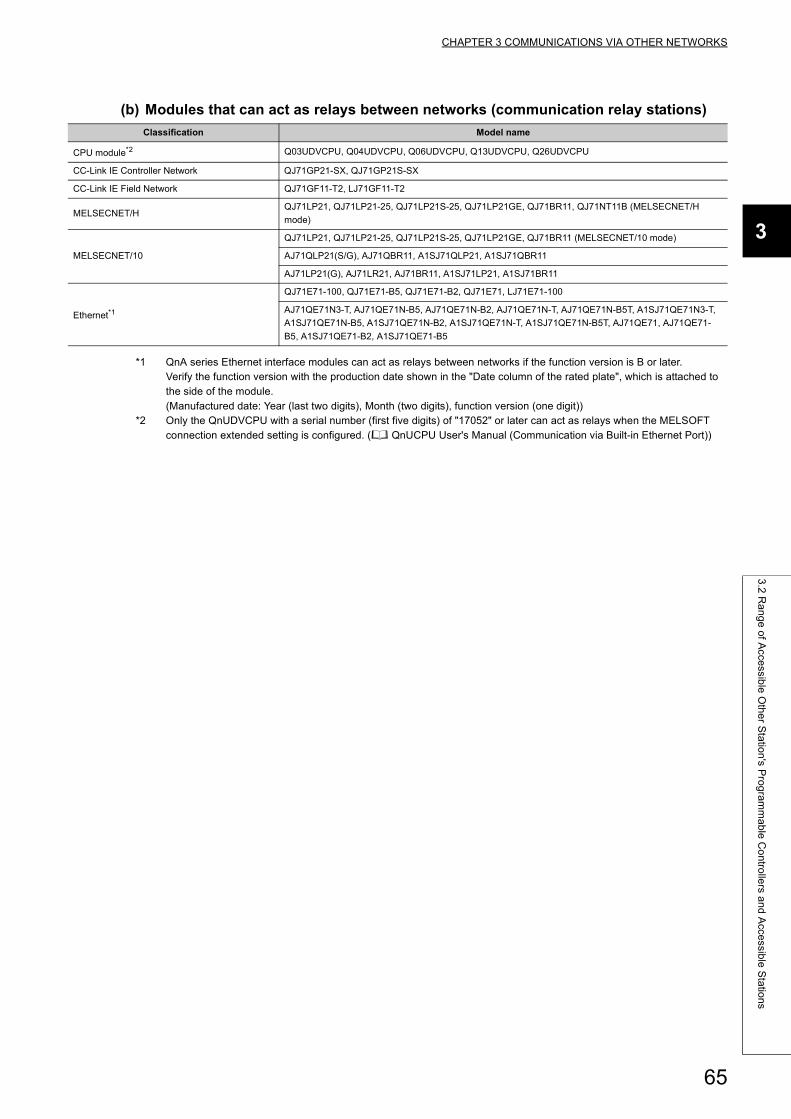
CHAPTER 3 COMMUNICATIONS VIA OTHER NETWORKS
3
3.2
Ra
ng
e o
f Acce
ssible
Oth
er S
tatio
n's P
rog
ram
ma
ble
Co
ntro
llers a
nd
Acce
ssible
Sta
tion
s
(b) Modules that can act as relays between networks (communication relay stations)
*1 QnA series Ethernet interface modules can act as relays between networks if the function version is B or later.Verify the function version with the production date shown in the "Date column of the rated plate", which is attached to the side of the module.(Manufactured date: Year (last two digits), Month (two digits), function version (one digit))
*2 Only the QnUDVCPU with a serial number (first five digits) of "17052" or later can act as relays when the MELSOFT connection extended setting is configured. ( QnUCPU User's Manual (Communication via Built-in Ethernet Port))
Classification Model name
CPU module*2 Q03UDVCPU, Q04UDVCPU, Q06UDVCPU, Q13UDVCPU, Q26UDVCPU
CC-Link IE Controller Network QJ71GP21-SX, QJ71GP21S-SX
CC-Link IE Field Network QJ71GF11-T2, LJ71GF11-T2
MELSECNET/HQJ71LP21, QJ71LP21-25, QJ71LP21S-25, QJ71LP21GE, QJ71BR11, QJ71NT11B (MELSECNET/H
mode)
MELSECNET/10
QJ71LP21, QJ71LP21-25, QJ71LP21S-25, QJ71LP21GE, QJ71BR11 (MELSECNET/10 mode)
AJ71QLP21(S/G), AJ71QBR11, A1SJ71QLP21, A1SJ71QBR11
AJ71LP21(G), AJ71LR21, AJ71BR11, A1SJ71LP21, A1SJ71BR11
Ethernet*1
QJ71E71-100, QJ71E71-B5, QJ71E71-B2, QJ71E71, LJ71E71-100
AJ71QE71N3-T, AJ71QE71N-B5, AJ71QE71N-B2, AJ71QE71N-T, AJ71QE71N-B5T, A1SJ71QE71N3-T,
A1SJ71QE71N-B5, A1SJ71QE71N-B2, A1SJ71QE71N-T, A1SJ71QE71N-B5T, AJ71QE71, AJ71QE71-
B5, A1SJ71QE71-B2, A1SJ71QE71-B5
65
3.3 Settings for Accessing Other Stations
This section explains the parameters and setting items that need to be set with a programming tool to access other
stations via the Ethernet using the CC-Link IE Controller Network, CC-Link IE Field Network, MELSECNET/H,
MELSECNET/10 relay communication function.
(1) Network parameter• Network No., group number, station number (station No.), etc. for using the Ethernet module are set on this
screen.
• Make sure to set the values by seeing the User's Manual (Basic).
(2) Setting the Station No. <-> IP information• The Ethernet's routing method, correspondences of the Ethernet module's IP address and Network
No./station number, etc. for using the CC-Link IE Controller Network, CC-Link IE Field Network,
MELSECNET/H, MELSECNET/10 relay communication function are set on this screen.
• Set these values by seeing Page 67, Section 3.3.1.
(3) Routing information setting• On this screen, the routing parameters between Ethernet modules for accessing other stations on other
networks are set, in the same way as for the routing parameter settings of other networks.*1
• These settings are required for a station where two or more Ethernet modules or network modules are
connected.
• Set these values by seeing Page 76, Section 3.3.3.
*1 The Network No. and station number of the first communication relay station as seen from the own station are set.
66
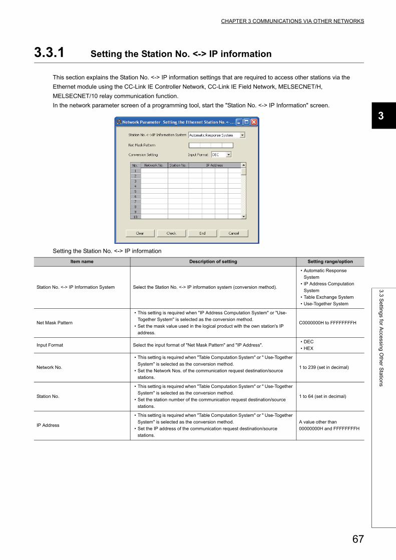
CHAPTER 3 COMMUNICATIONS VIA OTHER NETWORKS
3
3.3
Se
tting
s for A
ccessin
g O
the
r Sta
tion
s
3.3.1 Setting the Station No. <-> IP information
This section explains the Station No. <-> IP information settings that are required to access other stations via the
Ethernet module using the CC-Link IE Controller Network, CC-Link IE Field Network, MELSECNET/H,
MELSECNET/10 relay communication function.
In the network parameter screen of a programming tool, start the "Station No. <-> IP Information" screen.
Setting the Station No. <-> IP information
Item name Description of setting Setting range/option
Station No. <-> IP Information System Select the Station No. <-> IP information system (conversion method).
• Automatic Response
System
• IP Address Computation
System
• Table Exchange System
• Use-Together System
Net Mask Pattern
• This setting is required when "IP Address Computation System" or "Use-
Together System" is selected as the conversion method.
• Set the mask value used in the logical product with the own station's IP
address.
C0000000H to FFFFFFFFH
Input Format Select the input format of "Net Mask Pattern" and "IP Address".• DEC
• HEX
Network No.
• This setting is required when "Table Computation System" or " Use-Together
System" is selected as the conversion method.
• Set the Network Nos. of the communication request destination/source
stations.
1 to 239 (set in decimal)
Station No.
• This setting is required when "Table Computation System" or " Use-Together
System" is selected as the conversion method.
• Set the station number of the communication request destination/source
stations.
1 to 64 (set in decimal)
IP Address
• This setting is required when "Table Computation System" or " Use-Together
System" is selected as the conversion method.
• Set the IP address of the communication request destination/source
stations.
A value other than
00000000H and FFFFFFFFH
67
(1) Station No. <-> IP information system (conversion method) (address: 4H ... b7,
b6)
(a) There are four kinds of Station No. <-> IP information methods as shown below.
(b) Select one of them according to Page 70, Section 3.3.2 and make sure to set the
values on this screen using the method selected. (The default conversion method is
the Automatic response method.)
Parameter settings requirement
: Setting required, : Setting not required
(2) Net mask pattern (address: 3A9H)Designate the mask value based on the guidelines given below. This pattern is used in a logical sum with the own
station's IP address when calculating the IP address of the external device using the IP address computation
system.
(a) When setting the sub-net mask, designate the target settings of the IP address
class, network address, and sub-net address so that all bits are "1" in the mask
pattern.
The mask pattern is designated with a decimal/hexadecimal value obtained by dividing the 32-bit mask value
into 8-bit segments.
(b) When the sub-net mask is not designated, the mask pattern designation is not
necessary.
When the mask pattern is not designated, the following mask value is used as the mask pattern according to
the own station IP Address class.
Conversion method Net mask pattern Conversion setting
Automatic response system
IP address computation system
Table exchange system
Use-together system
Class Mask value used
Class A FF.00.00.00H
Class B FF.FF.00.00H
Class C FF.FF.FF.00H
68
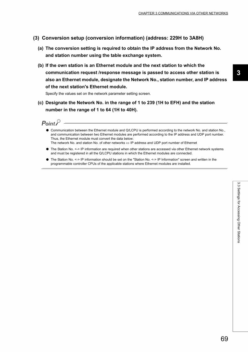
CHAPTER 3 COMMUNICATIONS VIA OTHER NETWORKS
3
3.3
Se
tting
s for A
ccessin
g O
the
r Sta
tion
s
(3) Conversion setup (conversion information) (address: 229H to 3A8H)
(a) The conversion setting is required to obtain the IP address from the Network No.
and station number using the table exchange system.
(b) If the own station is an Ethernet module and the next station to which the
communication request /response message is passed to access other station is
also an Ethernet module, designate the Network No., station number, and IP address
of the next station's Ethernet module.
Specify the values set on the network parameter setting screen.
(c) Designate the Network No. in the range of 1 to 239 (1H to EFH) and the station
number in the range of 1 to 64 (1H to 40H).
● Communication between the Ethernet module and Q/LCPU is performed according to the network No. and station No., and communication between two Ethernet modules are performed according to the IP address and UDP port number.Thus, the Ethernet module must convert the data below:The network No. and station No. of other networks IP address and UDP port number of Ethernet
● The Station No. <-> IP information are required when other stations are accessed via other Ethernet network systems and must be registered in all the Q/LCPU stations in which the Ethernet modules are connected.
● The Station No. <-> IP information should be set on the "Station No. <-> IP Information" screen and written in the programmable controller CPUs of the applicable stations where Ethernet modules are installed.
69
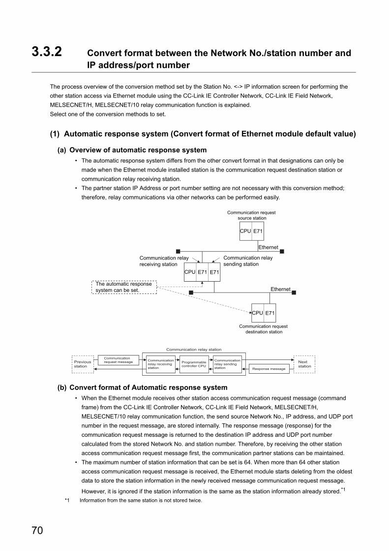
3.3.2 Convert format between the Network No./station number and IP address/port number
The process overview of the conversion method set by the Station No. <-> IP information screen for performing the
other station access via Ethernet module using the CC-Link IE Controller Network, CC-Link IE Field Network,
MELSECNET/H, MELSECNET/10 relay communication function is explained.
Select one of the conversion methods to set.
(1) Automatic response system (Convert format of Ethernet module default value)
(a) Overview of automatic response system
• The automatic response system differs from the other convert format in that designations can only be
made when the Ethernet module installed station is the communication request destination station or
communication relay receiving station.
• The partner station IP Address or port number setting are not necessary with this conversion method;
therefore, relay communications via other networks can be performed easily.
(b) Convert format of Automatic response system
• When the Ethernet module receives other station access communication request message (command
frame) from the CC-Link IE Controller Network, CC-Link IE Field Network, MELSECNET/H,
MELSECNET/10 relay communication function, the send source Network No., IP address, and UDP port
number in the request message, are stored internally. The response message (response) for the
communication request message is returned to the destination IP address and UDP port number
calculated from the stored Network No. and station number. Therefore, by receiving the other station
access communication request message first, the communication partner stations can be maintained.
• The maximum number of station information that can be set is 64. When more than 64 other station
access communication request message is received, the Ethernet module starts deleting from the oldest
data to store the station information in the newly received message communication request message.
However, it is ignored if the station information is the same as the station information already stored.*1
*1 Information from the same station is not stored twice.
E71CPU
Ethernet
Ethernet
Communication relay receiving station
Communication relay sending station
Communication request source station
Communication request destination station
The automatic response system can be set.
E71CPU E71
E71CPU
Communicationrequest messagePrevious
stationResponse message
Nextstation
Communicationrelay receivingstation
Communicationrelay sendingstation
Programmablecontroller CPU
Communication relay station
70
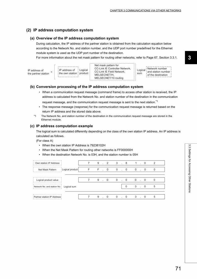
CHAPTER 3 COMMUNICATIONS VIA OTHER NETWORKS
3
3.3
Se
tting
s for A
ccessin
g O
the
r Sta
tion
s
(2) IP address computation system
(a) Overview of the IP address computation system
During calculation, the IP address of the partner station is obtained from the calculation equation below
according to the Network No. and station number, and the UDP port number predefined for the Ethernet
module system is used as the UDP port number of the destination.
For more information about the net mask pattern for routing other networks, refer to Page 67, Section 3.3.1.
(b) Conversion processing of the IP address computation system
• When a communication request message (command frame) to access other station is received, the IP
address is calculated from the Network No. and station number of the destination in the communication
request message, and the communication request message is sent to the next station.*1
• The response message (response) for the communication request message is returned based on the
return IP address and the stored data above.
*1 The Network No. and station number of the destination in the communication request message are stored in the Ethernet module.
(c) IP address computation example
The logical sum is calculated differently depending on the class of the own station IP address. An IP address is
calculated as follows.
(For class A)
• When the own station IP Address is 79238102H
• When the Net Mask Pattern for routing other networks is FF000000H
• When the destination Network No. is 03H, and the station number is 05H
IP address of the partner station =
Logical product
Logical sum
IP address of the own station
Network number and station number of the destination
Net mask pattern for CC-Link IE Controller Network, CC-Link IE Field Network, MELSECNET/H, MELSECNET/10 routing
7 9 . 2 3 . 8 1 . 0 2
F F . 0 0 . 0 0 . 0 0
7 9 . 0 0 . 0 0 . 0 0
0 3 . 0 5
7 9 . 0 0 . 0 3 . 0 5
Own station IP Address
Net Mask Pattern Logical product
Logical product value
Network No. and station No. Logical sum
Partner station IP Address
71
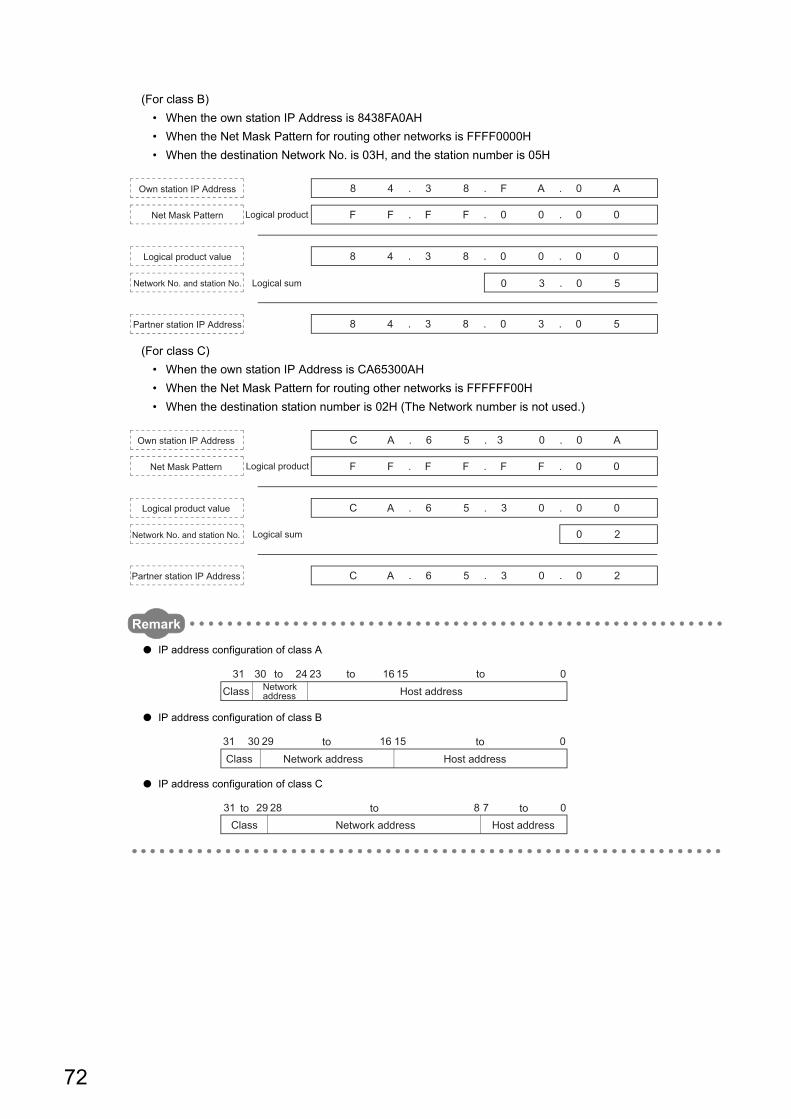
(For class B)
• When the own station IP Address is 8438FA0AH
• When the Net Mask Pattern for routing other networks is FFFF0000H
• When the destination Network No. is 03H, and the station number is 05H
(For class C)
• When the own station IP Address is CA65300AH
• When the Net Mask Pattern for routing other networks is FFFFFF00H
• When the destination station number is 02H (The Network number is not used.)
Remark
● IP address configuration of class A
● IP address configuration of class B
● IP address configuration of class C
8 4 . 3 8 . F A . 0 A
F F . F F . 0 0 . 0 0
8 4 . 3 8 . 0 0 . 0 0
0 3 . 0 5
8 4 . 3 8 . 0 3 . 0 5
Own station IP Address
Net Mask Pattern Logical product
Logical product value
Network No. and station No. Logical sum
Partner station IP Address
F F . F F . F F . 0 0
C A . 6 5 . 3 0 . 0 0
0 2
C A . 6 5 . 3 0 . 0 2
C A . 6 5 . 0 . 0 A3Own station IP Address
Net Mask Pattern Logical product
Logical product value
Network No. and station No. Logical sum
Partner station IP Address
31 30 24 23 016 15Class Network
address
to toHost address
to
29 015163031Host addressNetwork address
totoClass
828 072931Host addressNetwork address
to totoClass
72
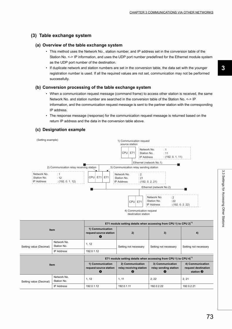
CHAPTER 3 COMMUNICATIONS VIA OTHER NETWORKS
3
3.3
Se
tting
s for A
ccessin
g O
the
r Sta
tion
s
(3) Table exchange system
(a) Overview of the table exchange system
• This method uses the Network No., station number, and IP address set in the conversion table of the
Station No. <-> IP information, and uses the UDP port number predefined for the Ethernet module system
as the UDP port number of the destination.
• If duplicate network and station numbers are set in the conversion table, the data set with the younger
registration number is used. If all the required values are not set, communication may not be performed
successfully.
(b) Conversion processing of the table exchange system
• When a communication request message (command frame) to access other station is received, the same
Network No. and station number are searched in the conversion table of the Station No. <-> IP
information, and the communication request message is sent to the partner station with the corresponding
IP address.
• The response message (response) for the communication request message is returned based on the
return IP address and the data in the conversion table above.
(c) Designation example
Item
E71 module setting details when accessing from CPU 1) to CPU 2)*1
1) Communication
request source station
2) 3) 4)
Setting value (Decimal)
Network No.
Station No.1, 12
Setting not necessary Setting not necessary Setting not necessary
IP Address 192.0.1.12
Item
E71 module setting details when accessing from CPU 1) to CPU 4)*1
1) Communication
request source station
2) Communication
relay receiving station
3) Communication
relay sending station
4) Communication
request destination
station
Setting value (Decimal)
Network No.
Station No.1, 12 1, 11 2, 22 2, 21
IP Address 192.0.1.12 192.0.1.11 192.0.2.22 192.0.2.21
E71CPU
Ethernet (network No.1)
Ethernet (network No.2)
2) Communication relay receiving station 3) Communication relay sending station
1) Communication request source station
4) Communication request destination station
(Setting example)
E71CPU E71
E71CPU
Network No.Station No.
: 2: 22: (192. 0. 2. 22)
Network No.Station No.
: 2: 21: (192. 0. 2. 21)
Network No.Station No.
: 1: 12: (192. 0. 1. 12)
Network No.Station No.
: 1: 11: (192. 0. 1. 11)IP Address
IP Address IP Address
IP Address
73
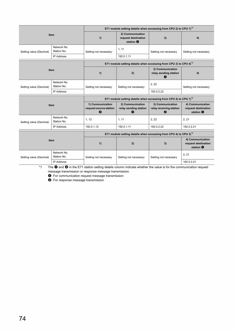
*1 The and in the E71 station setting details column indicate whether the value is for the communication request message transmission or response message transmission.: For communication request message transmission: For response message transmission
Item
E71 module setting details when accessing from CPU 2) to CPU 1)*1
1)
2) Communication
request destination
station
3) 4)
Setting value (Decimal)
Network No.
Station No. Setting not necessary1, 11
Setting not necessary Setting not necessary
IP Address 192.0.1.11
Item
E71 module setting details when accessing from CPU 3) to CPU 4)*1
1) 2)
3) Communication
relay sending station
4)
Setting value (Decimal)
Network No.
Station No. Setting not necessary Setting not necessary2, 22
Setting not necessary
IP Address 192.0.2.22
Item
E71 module setting details when accessing from CPU 4) to CPU 1)*1
1) Communication
request source station
2) Communication
relay sending station
3) Communication
relay receiving station
4) Communication
request destination
station
Setting value (Decimal)
Network No.
Station No.1, 12 1, 11 2, 22 2, 21
IP Address 192.0.1.12 192.0.1.11 192.0.2.22 192.0.2.21
Item
E71 module setting details when accessing from CPU 4) to CPU 3)*1
1) 2) 3)
4) Communication
request destination
station
Setting value (Decimal)
Network No.
Station No. Setting not necessary Setting not necessary Setting not necessary2, 21
IP Address 192.0.2.21
74
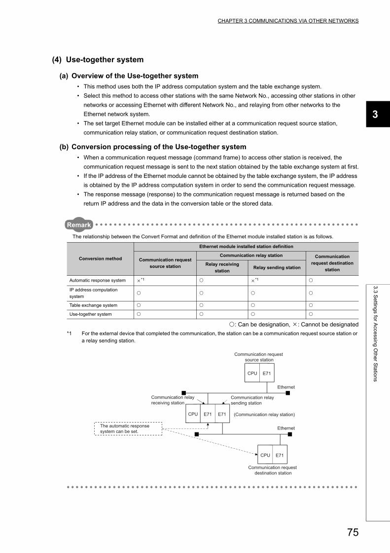
CHAPTER 3 COMMUNICATIONS VIA OTHER NETWORKS
3
3.3
Se
tting
s for A
ccessin
g O
the
r Sta
tion
s
(4) Use-together system
(a) Overview of the Use-together system
• This method uses both the IP address computation system and the table exchange system.
• Select this method to access other stations with the same Network No., accessing other stations in other
networks or accessing Ethernet with different Network No., and relaying from other networks to the
Ethernet network system.
• The set target Ethernet module can be installed either at a communication request source station,
communication relay station, or communication request destination station.
(b) Conversion processing of the Use-together system
• When a communication request message (command frame) to access other station is received, the
communication request message is sent to the next station obtained by the table exchange system at first.
• If the IP address of the Ethernet module cannot be obtained by the table exchange system, the IP address
is obtained by the IP address computation system in order to send the communication request message.
• The response message (response) to the communication request message is returned based on the
return IP address and the data in the conversion table or the stored data.
Remark
The relationship between the Convert Format and definition of the Ethernet module installed station is as follows.
: Can be designation, : Cannot be designated
*1 For the external device that completed the communication, the station can be a communication request source station or a relay sending station.
Conversion method
Ethernet module installed station definition
Communication request
source station
Communication relay station Communication
request destination
stationRelay receiving
stationRelay sending station
Automatic response system *1 *1
IP address computation
system
Table exchange system
Use-together system
Ethernet
Ethernet
Communication relay receiving station
Communication relay sending station
Communication request source station
Communication request destination station
The automatic response system can be set.
E71CPU
(Communication relay station)
E71CPU
E71CPU E71
75
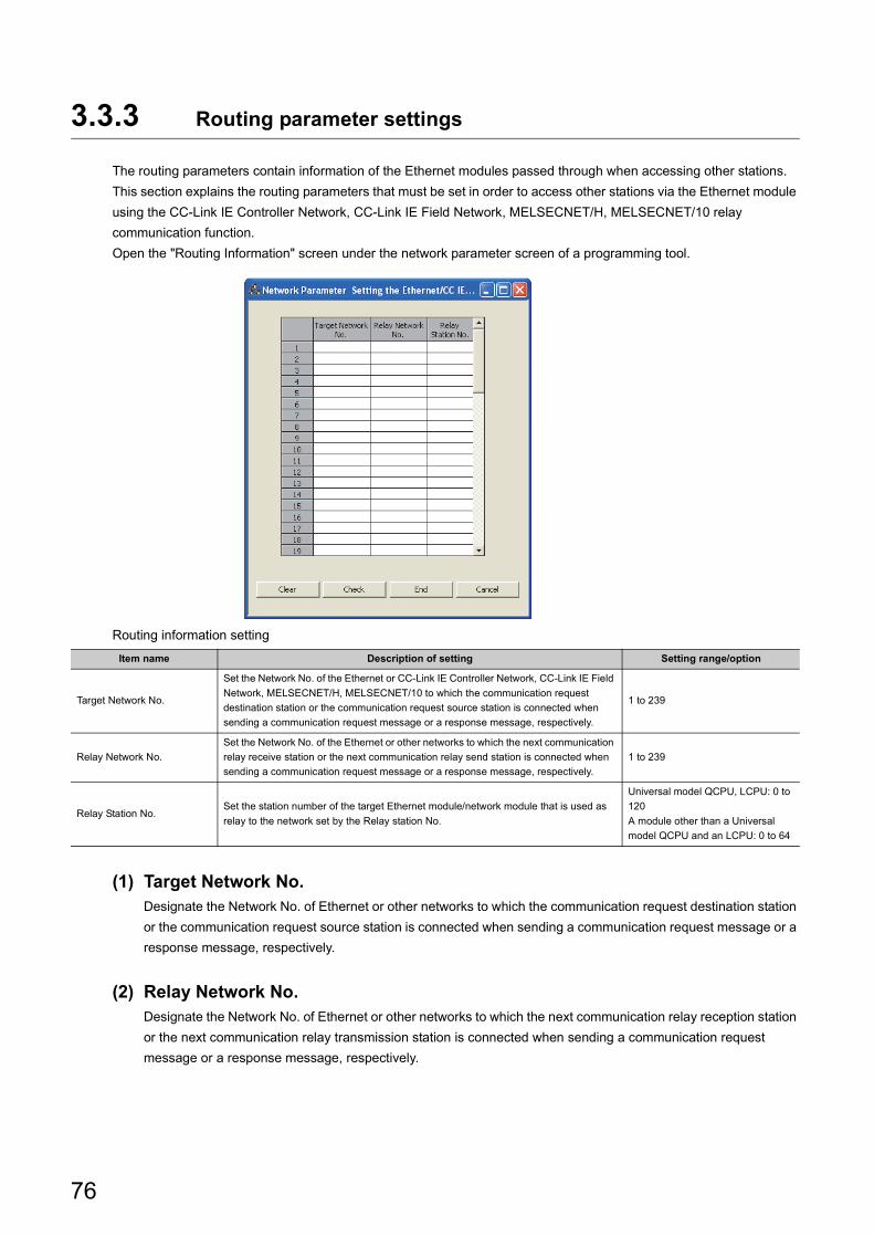
3.3.3 Routing parameter settings
The routing parameters contain information of the Ethernet modules passed through when accessing other stations.
This section explains the routing parameters that must be set in order to access other stations via the Ethernet module
using the CC-Link IE Controller Network, CC-Link IE Field Network, MELSECNET/H, MELSECNET/10 relay
communication function.
Open the "Routing Information" screen under the network parameter screen of a programming tool.
Routing information setting
(1) Target Network No.Designate the Network No. of Ethernet or other networks to which the communication request destination station
or the communication request source station is connected when sending a communication request message or a
response message, respectively.
(2) Relay Network No.Designate the Network No. of Ethernet or other networks to which the next communication relay reception station
or the next communication relay transmission station is connected when sending a communication request
message or a response message, respectively.
Item name Description of setting Setting range/option
Target Network No.
Set the Network No. of the Ethernet or CC-Link IE Controller Network, CC-Link IE Field
Network, MELSECNET/H, MELSECNET/10 to which the communication request
destination station or the communication request source station is connected when
sending a communication request message or a response message, respectively.
1 to 239
Relay Network No.
Set the Network No. of the Ethernet or other networks to which the next communication
relay receive station or the next communication relay send station is connected when
sending a communication request message or a response message, respectively.
1 to 239
Relay Station No.Set the station number of the target Ethernet module/network module that is used as
relay to the network set by the Relay station No.
Universal model QCPU, LCPU: 0 to
120
A module other than a Universal
model QCPU and an LCPU: 0 to 64
76
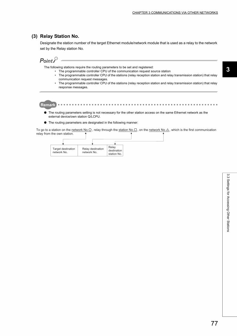
CHAPTER 3 COMMUNICATIONS VIA OTHER NETWORKS
3
3.3
Se
tting
s for A
ccessin
g O
the
r Sta
tion
s
(3) Relay Station No.Designate the station number of the target Ethernet module/network module that is used as a relay to the network
set by the Relay station No.
The following stations require the routing parameters to be set and registered:• The programmable controller CPU of the communication request source station• The programmable controller CPU of the stations (relay reception station and relay transmission station) that relay
communication request messages.• The programmable controller CPU of the stations (relay reception station and relay transmission station) that relay
response messages.
Remark
● The routing parameters setting is not necessary for the other station access on the same Ethernet network as the external device/own station Q/LCPU.
● The routing parameters are designated in the following manner:
Target destination network No.
Relay destination network No.
Relay destination station No.
To go to a station on the network No. , relay through the station No. , on the network No. , which is the first communication relay from the own station.
77
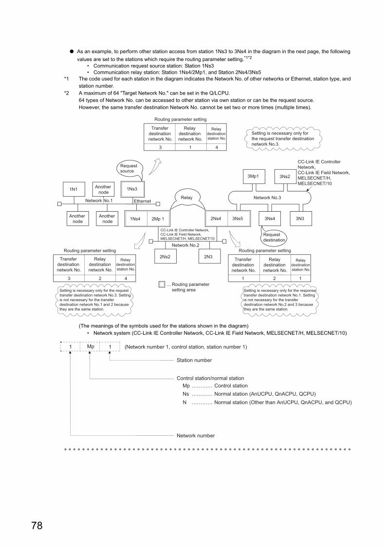
● As an example, to perform other station access from station 1Ns3 to 3Ns4 in the diagram in the next page, the following
values are set to the stations which require the routing parameter setting.*1*2
• Communication request source station: Station 1Ns3• Communication relay station: Station 1Ns4/2Mp1, and Station 2Ns4/3Ns5
*1 The code used for each station in the diagram indicates the Network No. of other networks or Ethernet, station type, and station number.
*2 A maximum of 64 "Target Network No." can be set in the Q/LCPU.64 types of Network No. can be accessed to other station via own station or can be the request source.However, the same transfer destination Network No. cannot be set two or more times (multiple times).
(The meanings of the symbols used for the stations shown in the diagram)• Network system (CC-Link IE Controller Network, CC-Link IE Field Network, MELSECNET/H, MELSECNET/10)
3Mp1 3Ns2
3Ns4 3N3
Network No.3
3Ns52Ns4
2N32Ns2
Network No.2
2Mp 11Ns4Another node
Another node
Another node1N1
Network No.1 Ethernet
CC-Link IE Controller Network, CC-Link IE Field Network, MELSECNET/H, MELSECNET/10
CC-Link IE Controller Network, CC-Link IE Field Network, MELSECNET/H, MELSECNET/10
1Ns3
Relay
Requestdestination
Requestsource
1 2 1
Routing parameter setting
3 2 4
Routing parameter setting
Setting is necessary only for the request transfer destination network No.3. Setting is not necessary for the transfer destination network No.1 and 2 because they are the same station.
Setting is necessary only for the response transfer destination network No.1. Setting is not necessary for the transfer destination network No.2 and 3 because they are the same station.
3 1 4
Routing parameter setting
Transfer destination network No.
Relay destination network No.
Relay destination station No.
Setting is necessary only for the request transfer destination network No.3.
... Routing parameter setting area
Transfer destination network No.
Relay destination network No.
Relay destination station No.
Transfer destination network No.
Relay destination network No.
Relay destination station No.
MpNsN
Mp 11
………… Control station
Station number
Control station/normal station
………… Normal station (AnUCPU, QnACPU, QCPU)………… Normal station (Other than AnUCPU, QnACPU, and QCPU)
Network number
(Network number 1, control station, station number 1)
78
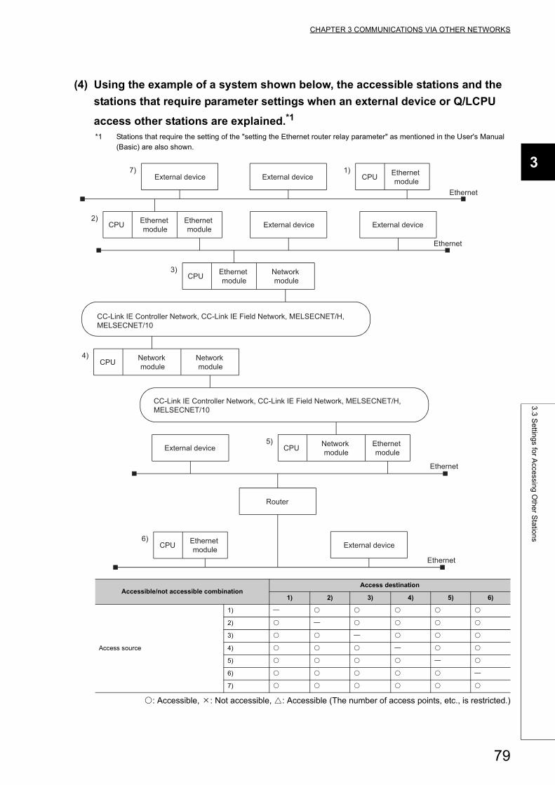
CHAPTER 3 COMMUNICATIONS VIA OTHER NETWORKS
3
3.3
Se
tting
s for A
ccessin
g O
the
r Sta
tion
s
(4) Using the example of a system shown below, the accessible stations and the
stations that require parameter settings when an external device or Q/LCPU
access other stations are explained.*1
*1 Stations that require the setting of the "setting the Ethernet router relay parameter" as mentioned in the User's Manual (Basic) are also shown.
: Accessible, : Not accessible, : Accessible (The number of access points, etc., is restricted.)
Accessible/not accessible combinationAccess destination
1) 2) 3) 4) 5) 6)
Access source
1)
2)
3)
4)
5)
6)
7)
CPU
Ethernet
CPU
Ethernet
CPU
CC-Link IE Controller Network, CC-Link IE Field Network, MELSECNET/H, MELSECNET/10
CC-Link IE Controller Network, CC-Link IE Field Network, MELSECNET/H, MELSECNET/10
CPU
CPU
Router
Ethernet
CPU
Ethernet
1)7)
2)
3)
4)
5)
6)
External device
External device
External device
External device
External device External device
Ethernet module
Ethernet module
Ethernet module
Ethernet module
Ethernet module
Ethernet module
Network module
Network module
Network module
Network module
79
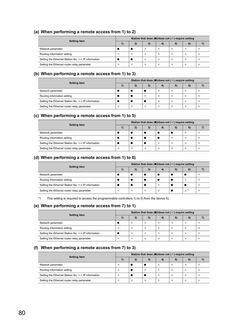
(a) When performing a remote access from 1) to 2)
(b) When performing a remote access from 1) to 3)
(c) When performing a remote access from 1) to 5)
(d) When performing a remote access from 1) to 6)
*1 This setting is required to access the programmable controllers 1) to 5) from the device 6).
(e) When performing a remote access from 7) to 1)
(f) When performing a remote access from 7) to 3)
Setting itemStation that does (●)/does not () require setting
1) 2) 3) 4) 5) 6) 7)
Network parameter ● ●
Routing information setting
Setting the Ethernet Station No. <-> IP information ● ●
Setting the Ethernet router relay parameter
Setting itemStation that does (●)/does not () require setting
1) 2) 3) 4) 5) 6) 7)
Network parameter ● ● ●
Routing information setting ● ●
Setting the Ethernet Station No. <-> IP information ● ● ●
Setting the Ethernet router relay parameter
Setting itemStation that does (●)/does not () require setting
1) 2) 3) 4) 5) 6) 7)
Network parameter ● ● ● ● ●
Routing information setting ● ● ● ●
Setting the Ethernet Station No. <-> IP information ● ● ●
Setting the Ethernet router relay parameter
Setting itemStation that does (●)/does not () require setting
1) 2) 3) 4) 5) 6) 7)
Network parameter ● ● ● ● ● ●
Routing information setting ● ● ● ● ●
Setting the Ethernet Station No. <-> IP information ● ● ● ● ●
Setting the Ethernet router relay parameter ● *1
Setting itemStation that does (●)/does not () require setting
1) 2) 3) 4) 5) 6) 7)
Network parameter ●
Routing information setting
Setting the Ethernet Station No. <-> IP information ●
Setting the Ethernet router relay parameter
Setting itemStation that does (●)/does not () require setting
1) 2) 3) 4) 5) 6) 7)
Network parameter ● ●
Routing information setting ●
Setting the Ethernet Station No. <-> IP information ● ●
Setting the Ethernet router relay parameter
80
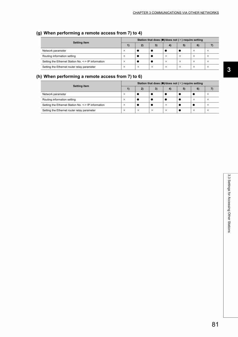
CHAPTER 3 COMMUNICATIONS VIA OTHER NETWORKS
3
3.3
Se
tting
s for A
ccessin
g O
the
r Sta
tion
s
(g) When performing a remote access from 7) to 4)
(h) When performing a remote access from 7) to 6)
Setting itemStation that does (●)/does not () require setting
1) 2) 3) 4) 5) 6) 7)
Network parameter ● ● ● ●
Routing information setting ● ●
Setting the Ethernet Station No. <-> IP information ● ●
Setting the Ethernet router relay parameter
Setting itemStation that does (●)/does not () require setting
1) 2) 3) 4) 5) 6) 7)
Network parameter ● ● ● ● ●
Routing information setting ● ● ● ●
Setting the Ethernet Station No. <-> IP information ● ● ● ●
Setting the Ethernet router relay parameter ●
81
3.4 Procedure for Accessing Other Stations
This section explains the procedure for accessing other stations via the Ethernet using the CC-Link IE Controller
Network, CC-Link IE Field Network, MELSECNET/H, MELSECNET/10 relay communication function as well as the
required processing.
(1) Setting the parametersThe parameters shown in Page 66, Section 3.3 must be set using a programming tool.
(2) Accessing other stationsAccess to other stations is performed from an external device/own station Q/LCPU using the CC-Link IE
Controller Network, CC-Link IE Field Network, MELSECNET/H, MELSECNET/10 relay communication function.
Remark
• Access to other stations with the CC-Link IE Controller Network, CC-Link IE Field Network, MELSECNET/H, MELSECNET/10 relay communication function is performed using the UDP/IP protocol and data is always communicated in binary code.
• In the data communication, the port number (for the UDP/IP port) for the Ethernet module system is used.• It is possible to continue accessing other stations while the initial normal completion signal (X19) is on. When the
initial normal completion signal (X19) is turned off, the Ethernet module forcefully closes the connection although other station is being accessed.
(3) End processing of the Ethernet moduleWhen ending access to other station with the CC-Link IE Controller Network, CC-Link IE Field Network,
MELSECNET/H, MELSECNET/10 relay communication function that has been made using a connection opened
by user, execute the close processing of the connection by seeing the User's Manual (Basic).
When the following two functions are used to access other station, the close processing is not required.
• Communication using the data link instructions
• Communication with other stations using a programming tool
82
CHAPTER 3 COMMUNICATIONS VIA OTHER NETWORKS
3
3.5
Pre
cau
tion
s for A
ccessin
g O
the
r Sta
tion
s
3.5 Precautions for Accessing Other Stations
The following describes precautions when accessing other stations via the Ethernet module using the CC-Link IE
Controller Network, CC-Link IE Field Network, MELSECNET/H, MELSECNET/10 relay communication function.
• Set a network number different from that of another network. In addition, set a station number different from
that of an station in the same network.
• Access to other stations with the CC-Link IE Controller Network, CC-Link IE Field Network, MELSECNET/H,
MELSECNET/10 relay communication function is performed using the UDP/IP protocol and data is always
communicated in binary code.
Refer to the manual for each network module for the interlock signals and the send/receive processing and processing time of the link data when performing data communication with Q/LCPUs of other stations via other networks.
83
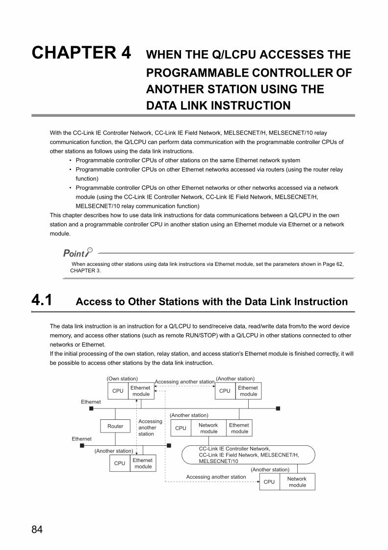
CHAPTER 4 WHEN THE Q/LCPU ACCESSES THE
PROGRAMMABLE CONTROLLER OF ANOTHER STATION USING THE DATA LINK INSTRUCTION
With the CC-Link IE Controller Network, CC-Link IE Field Network, MELSECNET/H, MELSECNET/10 relay
communication function, the Q/LCPU can perform data communication with the programmable controller CPUs of
other stations as follows using the data link instructions.
• Programmable controller CPUs of other stations on the same Ethernet network system
• Programmable controller CPUs on other Ethernet networks accessed via routers (using the router relay
function)
• Programmable controller CPUs on other Ethernet networks or other networks accessed via a network
module (using the CC-Link IE Controller Network, CC-Link IE Field Network, MELSECNET/H,
MELSECNET/10 relay communication function)
This chapter describes how to use data link instructions for data communications between a Q/LCPU in the own
station and a programmable controller CPU in another station using an Ethernet module via Ethernet or a network
module.
When accessing other stations using data link instructions via Ethernet module, set the parameters shown in Page 62, CHAPTER 3.
4.1 Access to Other Stations with the Data Link Instruction
The data link instruction is an instruction for a Q/LCPU to send/receive data, read/write data from/to the word device
memory, and access other stations (such as remote RUN/STOP) with a Q/LCPU in other stations connected to other
networks or Ethernet.
If the initial processing of the own station, relay station, and access station's Ethernet module is finished correctly, it will
be possible to access other stations by the data link instruction.
CPU CPU
CPU
CPURouter
Accessing another station
Accessing another station
Ethernet
Ethernet
CC-Link IE Controller Network, CC-Link IE Field Network, MELSECNET/H, MELSECNET/10
CPU
(Own station)
Ethernet module
Ethernet module
Ethernet module
Ethernet module
(Another station)
(Another station)
(Another station)
(Another station)
Accessing another station
Network module
Network module
84
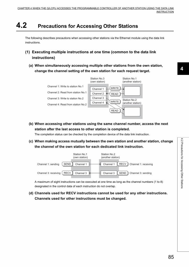
CHAPTER 4 WHEN THE Q/LCPU ACCESSES THE PROGRAMMABLE CONTROLLER OF ANOTHER STATION USING THE DATA LINKINSTRUCTION
4
4.2
Pre
cau
tion
s for A
ccessin
g O
the
r Sta
tion
s
4.2 Precautions for Accessing Other Stations
The following describes precautions when accessing other stations via the Ethernet module using the data link
instructions.
(1) Executing multiple instructions at one time (common to the data link
instructions)
(a) When simultaneously accessing multiple other stations from the own station,
change the channel setting of the own station for each request target.
(b) When accessing other stations using the same channel number, access the next
station after the last access to other station is completed.
The completion status can be checked by the completion device of the data link instruction.
(c) When making access mutually between the own station and another station, change
the channel of the own station for each dedicated link instruction.
A maximum of eight instructions can be executed at one time as long as the channel numbers (1 to 8)
designated in the control data of each instruction do not overlap.
(d) Channels used for RECV instructions cannot be used for any other instructions.
Channels used for other instructions must be changed.
WRITE
READ
READ
WRITE
Station No.3 (own station)
Station No.1 (another station)
Channel 1
Channel 2
Channel 3
Channel 4Station No.2 (another station)
Channel 1: Write to station No.1
Channel 2: Read from station No.1
Channel 3: Write to station No.2
Channel 4: Read from station No.2
SEND
RECV
RECV
SEND
Channel 1
Channel 3
Station No.1 (own station)
Station No.2 (another station)
Channel 1
Channel 3
Channel 1: sending
Channel 3: receiving
Channel 1: receiving
Channel 3: sending
85
(2) Setting the arrival monitoring time of the control data storage deviceWhen the setting unit of arrival monitoring time is "1s", set a value greater than or equal to the TCP resend timer
value set in the initial processing parameter for the arrival monitoring time designation area of the control data
storage device.
When the monitoring time is equal to or less than the TCP resend timer value, the TCP resend timer value is set
as the arrival monitoring time.*1
(When the setting value is less than or equal to the TCP resend timer value, the arrival monitoring timer equals
the TCP resend timer value.)
*1 Although the units of setting values for the TCP resend timer (setting value units: 0.5 s) and the arrival monitoring timer (setting value units: s) are different, the TCP resend timer value is used as is.
(3) Checking the execution result of each data link instructionThe execution result (completion status) of each data link instruction is stored in the areas shown as binary
values.
After the execution of an instruction is completed, read the execution result from the storage area and verify
either normal or abnormal completion.
• Stored value at normal completion: 0
• Stored value at abnormal completion: A value other than 0 (error code)
When an error code that indicates abnormal completion is stored, take an action by seeing the User's Manual
(Basic).
(4) Clock data when each of the data link instructions ends abnormallyIn the clock data stored as control data when each of the data link instructions ends abnormally (set only upon an
error), the year data (upper 2 digits) is stored only when the Q/LCPU is the error detection station. If the error
detection station is not a Q/LCPU, 00H is stored.
Instruction Storage area of execution result
SEND
The completion status storage device of the control data storage device of the instruction used.
RECV, RECVS
READ, SREAD
WRITE, SWRITE
REQ
ZNRD Data link instruction execution result storage area in buffer
memory
Address CFH (207)
ZNWR Address D1H (209)
86
CHAPTER 4 WHEN THE Q/LCPU ACCESSES THE PROGRAMMABLE CONTROLLER OF ANOTHER STATION USING THE DATA LINKINSTRUCTION
4
4.2
Pre
cau
tion
s for A
ccessin
g O
the
r Sta
tion
s
(5) Channels used by the ZNRD and ZNWR instructionsThe ZNRD and ZNWR instructions for Ethernet modules are executed using the following channels of the target
Ethernet module.
• ZNRD: Channel 1
• ZNWR: Channel 2
Do not use the channels used by the ZNRD and ZNWR instructions listed above for other data link instructions in
an Ethernet module mounted station that executes the ZNRD and ZNWR instructions.
Also, do not execute data link instructions from other stations on the channels listed above in an Ethernet module
mounted station that executes the ZNRD and ZNWR instructions.
● See Page 62, CHAPTER 3 for details of the following when performing other station access using the data link instructions.
• The accessible range and accessible stations of the other stations• Setting to perform other station access• Other station access procedure
● The communication using the data link instructions on the Ethernet is performed with UDP/IP.When executing each data link instruction except for ZNRD and ZNWR, it is recommended to designate a value greater than "1" to the number of retries setting area of the control data storage device.
● See the reference manual for each network regarding the link data send/receive processing and processing time in data communication with the programmable controller CPU of another station via other networks.
● For details of the data designation method for the data link instruction, refer to Page 155, CHAPTER 6.
87
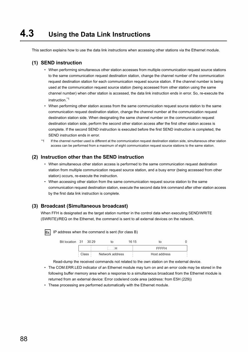
4.3 Using the Data Link Instructions
This section explains how to use the data link instructions when accessing other stations via the Ethernet module.
(1) SEND instruction• When performing simultaneous other station accesses from multiple communication request source stations
to the same communication request destination station, change the channel number of the communication
request destination station for each communication request source station. If the channel number is being
used at the communication request source station (being accessed from other station using the same
channel number) when other station is accessed, the data link instruction ends in error. So, re-execute the
instruction.*1
• When performing other station access from the same communication request source station to the same
communication request destination station, change the channel number at the communication request
destination station side. When designating the same channel number on the communication request
destination station side, perform the second other station access after the first other station access is
complete. If the second SEND instruction is executed before the first SEND instruction is completed, the
SEND instruction ends in error.
*1 If the channel number used is different at the communication request destination station side, simultaneous other station access can be performed from a maximum of eight communication request source stations to the same station.
(2) Instruction other than the SEND instruction• When simultaneous other station access is performed to the same communication request destination
station from multiple communication request source station, and a busy error (being accessed from other
station) occurs, re-execute the instruction.
• When accessing other station from the same communication request source station to the same
communication request destination station, execute the second data link command after other station access
by the first data link instruction is complete.
(3) Broadcast (Simultaneous broadcast)When FFH is designated as the target station number in the control data when executing SEND/WRITE
(SWRITE)/REQ on the Ethernet, the command is sent to all external devices on the network.
IP address when the command is sent (for class B)
Read-dump the received commands not related to the own station on the external device.
• The COM.ERR.LED indicator of an Ethernet module may turn on and an error code may be stored in the
following buffer memory area when a response to a simultaneous broadcast from the Ethernet module is
returned from an external device: Error code/end code area (address: from E5H (229))
• These processing are performed automatically with the Ethernet module.
H
31 30 29 16 15 0
FFFFH
Bit location to
Host addressNetwork address
to
Class
88
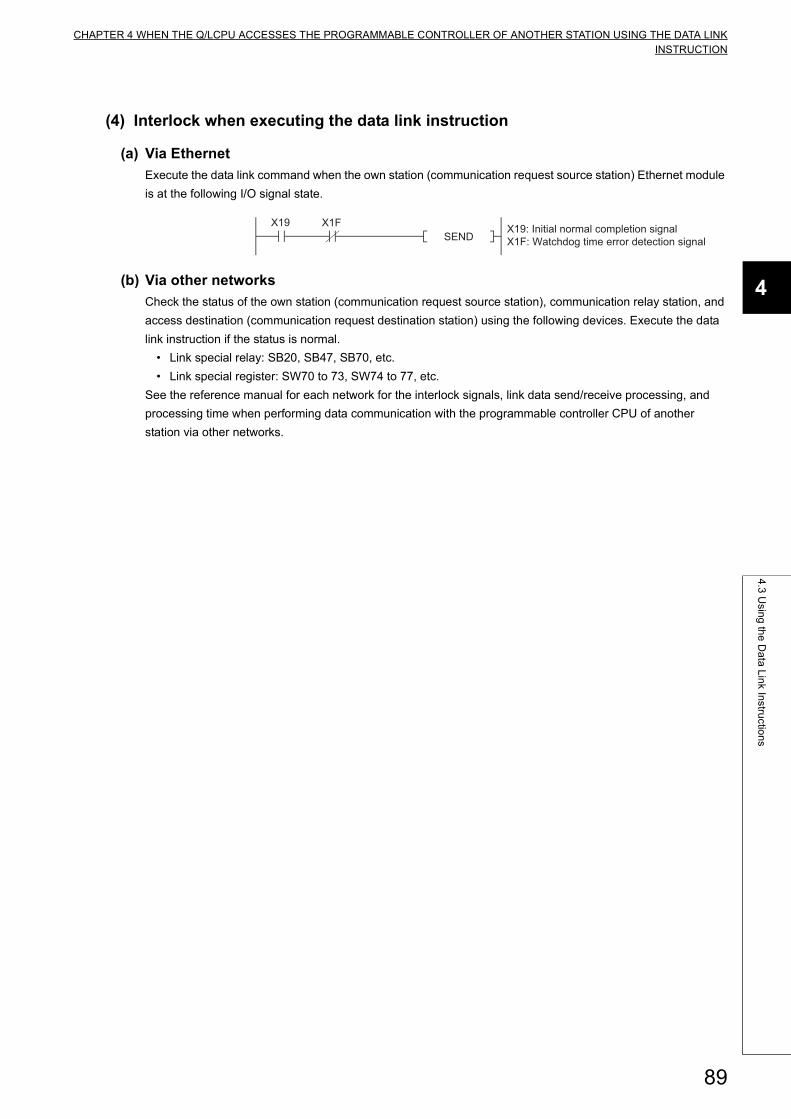
CHAPTER 4 WHEN THE Q/LCPU ACCESSES THE PROGRAMMABLE CONTROLLER OF ANOTHER STATION USING THE DATA LINKINSTRUCTION
4
4.3
Usin
g th
e D
ata
Lin
k Instru
ction
s
(4) Interlock when executing the data link instruction
(a) Via Ethernet
Execute the data link command when the own station (communication request source station) Ethernet module
is at the following I/O signal state.
(b) Via other networks
Check the status of the own station (communication request source station), communication relay station, and
access destination (communication request destination station) using the following devices. Execute the data
link instruction if the status is normal.
• Link special relay: SB20, SB47, SB70, etc.
• Link special register: SW70 to 73, SW74 to 77, etc.
See the reference manual for each network for the interlock signals, link data send/receive processing, and
processing time when performing data communication with the programmable controller CPU of another
station via other networks.
X19 X1FSEND
X19: Initial normal completion signalX1F: Watchdog time error detection signal
89
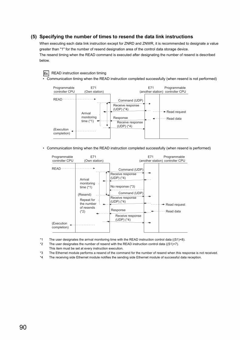
(5) Specifying the number of times to resend the data link instructionsWhen executing each data link instruction except for ZNRD and ZNWR, it is recommended to designate a value
greater than "1" for the number of resend designation area of the control data storage device.
The resend timing when the READ command is executed after designating the number of resend is described
below.
READ instruction execution timing
• Communication timing when the READ instruction completed successfully (when resend is not performed)
• Communication timing when the READ instruction completed successfully (when resend is performed)
*1 The user designates the arrival monitoring time with the READ instruction control data ((S1)+8).*2 The user designates the number of resend with the READ instruction control data ((S1)+7).
This item must be set at every instruction execution.*3 The Ethernet module performs a resend of the command for the number of resend when this response is not received.*4 The receiving side Ethernet module notifies the sending side Ethernet module of successful data reception.
Programmable controller CPU
E71 (Own station)
READ
(Execution completion)
Read request
Read data
E71 (another station)
Programmable controller CPU
Command (UDP)Receive response (UDP) (*4)
ResponseReceive response (UDP) (*4)
Arrival monitoring time (*1)
Programmable controller CPU
READ
Read request
Read data
E71 (another station)
Programmable controller CPU
Command (UDP)Receive response (UDP) (*4)
Command (UDP)Receive response (UDP) (*4)
Response
Receive response (UDP) (*4)
(Execution completion)
(Resend)
Arrival monitoring time (*1)
Repeat for the number of resends(*2)
No response (*3)
E71 (Own station)
90
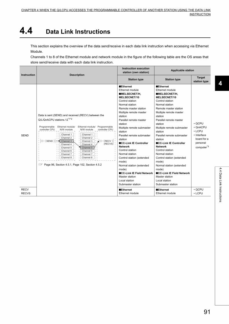
CHAPTER 4 WHEN THE Q/LCPU ACCESSES THE PROGRAMMABLE CONTROLLER OF ANOTHER STATION USING THE DATA LINKINSTRUCTION
4
4.4
Da
ta L
ink In
structio
ns
4.4 Data Link Instructions
This section explains the overview of the data send/receive in each data link instruction when accessing via Ethernet
Module.
Channels 1 to 8 of the Ethernet module and network module in the figure of the following table are the OS areas that
store send/receive data with each data link instruction.
Instruction Description
Instruction execution
station (own station)Applicable station
Station type Station typeTarget
station type
SEND
Data is sent (SEND) and received (RECV) between the
Q/L/QnACPU stations.12*1*2
Page 96, Section 4.5.1, Page 102, Section 4.5.2
■EthernetEthernet module
■MELSECNET/H, MELSECNET/10Control station
Normal station
Remote master station
Multiple remote master
station
Parallel remote master
station
Multiple remote submaster
station
Parallel remote submaster
station
■CC-Link IE Controller NetworkControl station
Normal station
Control station (extended
mode)
Normal station (extended
mode)
■CC-Link IE Field NetworkMaster station
Local station
Submaster station
• QCPU
• QnACPU
• LCPU
• Interface
board for a
personal
computer*3
RECV
RECVS■EthernetEthernet module
■EthernetEthernet module
• QCPU
• LCPU
Programmable controller CPU
Channel 1Channel 2Channel 3Channel 4Channel 5Channel 6Channel 7Channel 8
SEND RECV
Ethernet module/N/W module
Ethernet module/N/W module
Channel 1Channel 2Channel 3Channel 4Channel 5Channel 6Channel 7Channel 8
(RECVS)
Programmable controller CPU
91
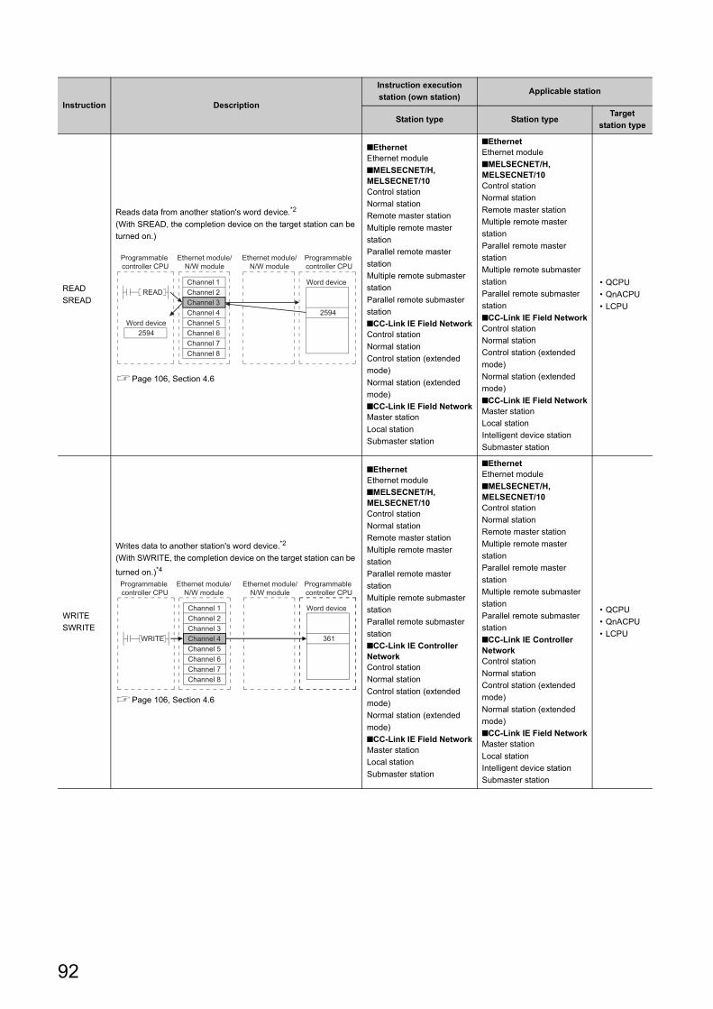
READ
SREAD
Reads data from another station's word device.*2
(With SREAD, the completion device on the target station can be
turned on.)
Page 106, Section 4.6
■EthernetEthernet module
■MELSECNET/H, MELSECNET/10Control station
Normal station
Remote master station
Multiple remote master
station
Parallel remote master
station
Multiple remote submaster
station
Parallel remote submaster
station
■CC-Link IE Field NetworkControl station
Normal station
Control station (extended
mode)
Normal station (extended
mode)
■CC-Link IE Field NetworkMaster station
Local station
Submaster station
■EthernetEthernet module
■MELSECNET/H, MELSECNET/10Control station
Normal station
Remote master station
Multiple remote master
station
Parallel remote master
station
Multiple remote submaster
station
Parallel remote submaster
station
■CC-Link IE Field NetworkControl station
Normal station
Control station (extended
mode)
Normal station (extended
mode)
■CC-Link IE Field NetworkMaster station
Local station
Intelligent device station
Submaster station
• QCPU
• QnACPU
• LCPU
WRITE
SWRITE
Writes data to another station's word device.*2
(With SWRITE, the completion device on the target station can be
turned on.)*4
Page 106, Section 4.6
■EthernetEthernet module
■MELSECNET/H, MELSECNET/10Control station
Normal station
Remote master station
Multiple remote master
station
Parallel remote master
station
Multiple remote submaster
station
Parallel remote submaster
station
■CC-Link IE Controller NetworkControl station
Normal station
Control station (extended
mode)
Normal station (extended
mode)
■CC-Link IE Field NetworkMaster station
Local station
Submaster station
■EthernetEthernet module
■MELSECNET/H, MELSECNET/10Control station
Normal station
Remote master station
Multiple remote master
station
Parallel remote master
station
Multiple remote submaster
station
Parallel remote submaster
station
■CC-Link IE Controller NetworkControl station
Normal station
Control station (extended
mode)
Normal station (extended
mode)
■CC-Link IE Field NetworkMaster station
Local station
Intelligent device station
Submaster station
• QCPU
• QnACPU
• LCPU
Instruction Description
Instruction execution
station (own station)Applicable station
Station type Station typeTarget
station type
Channel 1Channel 2Channel 3Channel 4Channel 5Channel 6Channel 7Channel 8
Word device
2594
READ
Word device2594
Programmable controller CPU
Ethernet module/N/W module
Ethernet module/N/W module
Programmable controller CPU
Programmable controller CPU
Programmable controller CPU
Channel 1Channel 2Channel 3Channel 4Channel 5Channel 6Channel 7Channel 8
Word device
WRITE 361
Ethernet module/N/W module
Ethernet module/N/W module
92
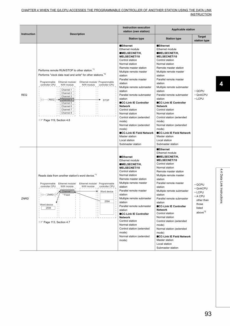
CHAPTER 4 WHEN THE Q/LCPU ACCESSES THE PROGRAMMABLE CONTROLLER OF ANOTHER STATION USING THE DATA LINKINSTRUCTION
4
4.4
Da
ta L
ink In
structio
ns
REQ
Performs remote RUN/STOP to other station.*1
Performs "clock data read and write" for other stations.*4
Page 119, Section 4.8
■EthernetEthernet module
■MELSECNET/H, MELSECNET/10Control station
Normal station
Remote master station
Multiple remote master
station
Parallel remote master
station
Multiple remote submaster
station
Parallel remote submaster
station
■CC-Link IE Controller NetworkControl station
Normal station
Control station (extended
mode)
Normal station (extended
mode)
■CC-Link IE Field NetworkMaster station
Local station
Submaster station
• QCPU
• QnACPU
• LCPU
ZNRD
Reads data from another station's word device.*1
Page 113, Section 4.7
■EthernetEthernet module
■MELSECNET/H, MELSECNET/10Control station
Normal station
Remote master station
Multiple remote master
station
Parallel remote master
station
Multiple remote submaster
station
Parallel remote submaster
station
■CC-Link IE Controller NetworkControl station
Normal station
Control station (extended
mode)
Normal station (extended
mode)
■CC-Link IE Field NetworkMaster station
Local station
Submaster station
• QCPU
• QnACPU
• LCPU
• A CPU
other than
those
listed
above*5
Instruction Description
Instruction execution
station (own station)Applicable station
Station type Station typeTarget
station type
Programmable controller CPU
Programmable controller CPU
Channel 1Channel 2Channel 3Channel 4Channel 5Channel 6Channel 7Channel 8
STOPREQ
Ethernet module/N/W module
Ethernet module/N/W module
2594
ZNRD
2594
Programmable controller CPU
Word device
Word device
Channel 1* Fixed
Programmable controller CPU
Ethernet module/N/W module
Ethernet module/N/W module
93
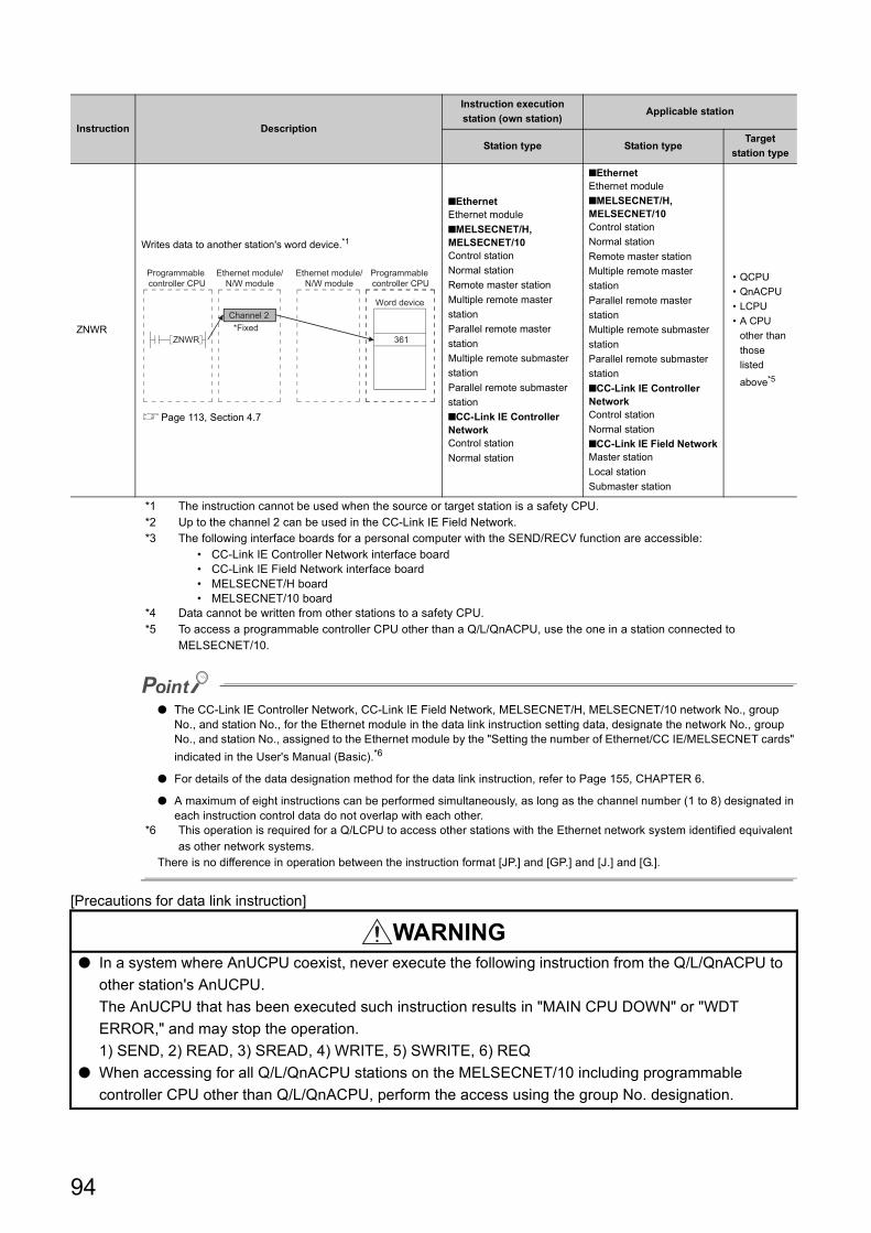
*1 The instruction cannot be used when the source or target station is a safety CPU.*2 Up to the channel 2 can be used in the CC-Link IE Field Network.*3 The following interface boards for a personal computer with the SEND/RECV function are accessible:
• CC-Link IE Controller Network interface board• CC-Link IE Field Network interface board• MELSECNET/H board• MELSECNET/10 board
*4 Data cannot be written from other stations to a safety CPU.*5 To access a programmable controller CPU other than a Q/L/QnACPU, use the one in a station connected to
MELSECNET/10.
● The CC-Link IE Controller Network, CC-Link IE Field Network, MELSECNET/H, MELSECNET/10 network No., group No., and station No., for the Ethernet module in the data link instruction setting data, designate the network No., group No., and station No., assigned to the Ethernet module by the "Setting the number of Ethernet/CC IE/MELSECNET cards"
indicated in the User's Manual (Basic).*6
● For details of the data designation method for the data link instruction, refer to Page 155, CHAPTER 6.
● A maximum of eight instructions can be performed simultaneously, as long as the channel number (1 to 8) designated in each instruction control data do not overlap with each other.
*6 This operation is required for a Q/LCPU to access other stations with the Ethernet network system identified equivalent as other network systems.
There is no difference in operation between the instruction format [JP.] and [GP.] and [J.] and [G.].
[Precautions for data link instruction]
ZNWR
Writes data to another station's word device.*1
Page 113, Section 4.7
■EthernetEthernet module
■MELSECNET/H, MELSECNET/10Control station
Normal station
Remote master station
Multiple remote master
station
Parallel remote master
station
Multiple remote submaster
station
Parallel remote submaster
station
■CC-Link IE Controller NetworkControl station
Normal station
■EthernetEthernet module
■MELSECNET/H, MELSECNET/10Control station
Normal station
Remote master station
Multiple remote master
station
Parallel remote master
station
Multiple remote submaster
station
Parallel remote submaster
station
■CC-Link IE Controller NetworkControl station
Normal station
■CC-Link IE Field NetworkMaster station
Local station
Submaster station
• QCPU
• QnACPU
• LCPU
• A CPU
other than
those
listed
above*5
WARNING● In a system where AnUCPU coexist, never execute the following instruction from the Q/L/QnACPU to
other station's AnUCPU.
The AnUCPU that has been executed such instruction results in "MAIN CPU DOWN" or "WDT
ERROR," and may stop the operation.
1) SEND, 2) READ, 3) SREAD, 4) WRITE, 5) SWRITE, 6) REQ
● When accessing for all Q/L/QnACPU stations on the MELSECNET/10 including programmable
controller CPU other than Q/L/QnACPU, perform the access using the group No. designation.
Instruction Description
Instruction execution
station (own station)Applicable station
Station type Station typeTarget
station type
361ZNWR
Programmable controller CPU
Word deviceChannel 2
Programmable controller CPU
Ethernet module/N/W module
Ethernet module/N/W module
*Fixed
94
CHAPTER 4 WHEN THE Q/LCPU ACCESSES THE PROGRAMMABLE CONTROLLER OF ANOTHER STATION USING THE DATA LINKINSTRUCTION
4
4.5
Da
ta S
en
din
g/R
ece
iving
4.5 Data Sending/Receiving
This section explains the arbitrary data sending/receiving function, instruction format and programs using the data
send/receive instructions (SEND, RECV and RECVS instructions).
(1) The SEND, RECV, and RECVS instructions are used for sending and receiving
arbitrary data to/from the programmable controller CPU with which
communicate is being performed.
(2) Data sending is performed using the SEND instruction and data receiving is
performed using the RECV or RECVS instruction.The RECV instruction and the RECVS instruction are used differently as follows.
(a) The RECV instruction is used in the receiving processing in the main program.
The main program reads from the RECV instruction executing request area in the buffer memory and executes
the RECV instruction using a switch from off to on of a bit corresponding to the data receiving channel number
as a trigger.
(b) The RECVS instruction is used in the receiving processing in an interrupt program.
An interrupt program is started when data is received from the programmable controller CPU with which
communication is being performed to enable receive data reading to the programmable controller CPU.
To start the interrupt program, set the parameters on the following screens of a programming tool.
• "Network Parameter Ethernet Interrupt Settings" screen
Set the control number (SI) on the Ethernet module side when an interrupt request is made to the
programmable controller CPU from the Ethernet module.
• "Intelligent Function Module Interrupt Pointer Setting" screen
Associate the control number (SI) set in the "Ethernet Interrupt Settings" above with the interrupt pointer (Ixx)
used in the sequence program.
The settings on the two screens above are the same as when received data is read by an interrupt program in
the fixed buffer communication.
For details on the settings and setting method on these screens, see the User's Manual (Basic).
● To start an interrupt program, the following settings with a programming tool and interrupt permission in a sequence program are required.
• Interrupt settings in the network parameter screen and intelligent function module interrupt pointer setting• Create interrupt enable/disable programs in the main program in order to start the interrupt program. Use the EI,
DI and IMASK instructions for this.
● In cases where receive data is read on the same channel, the main program for reading receive data and the interrupt program for reading receive data can not be used together.Please use one of the programs to read receive data.Received data cannot be read with the main program when the settings to read receive data with an interrupt program are being configured using a programming tool.
95
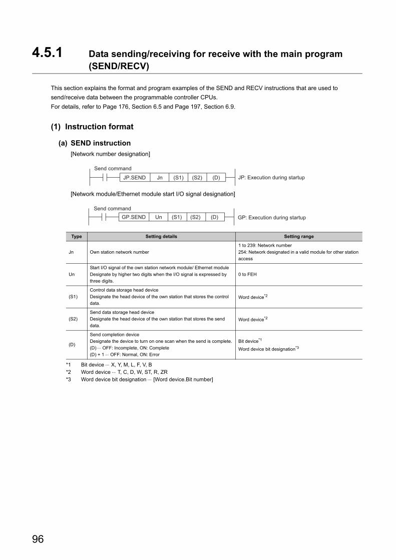
4.5.1 Data sending/receiving for receive with the main program (SEND/RECV)
This section explains the format and program examples of the SEND and RECV instructions that are used to
send/receive data between the programmable controller CPUs.
For details, refer to Page 176, Section 6.5 and Page 197, Section 6.9.
(1) Instruction format
(a) SEND instruction
[Network number designation]
[Network module/Ethernet module start I/O signal designation]
*1 Bit device X, Y, M, L, F, V, B*2 Word device T, C, D, W, ST, R, ZR*3 Word device bit designation [Word device.Bit number]
Type Setting details Setting range
Jn Own station network number
1 to 239: Network number
254: Network designated in a valid module for other station
access
Un
Start I/O signal of the own station network module/ Ethernet module
Designate by higher two digits when the I/O signal is expressed by
three digits.
0 to FEH
(S1)
Control data storage head device
Designate the head device of the own station that stores the control
data.Word device*2
(S2)
Send data storage head device
Designate the head device of the own station that stores the send
data.Word device*2
(D)
Send completion device
Designate the device to turn on one scan when the send is complete.
(D) OFF: Incomplete, ON: Complete
(D) + 1 OFF: Normal, ON: Error
Bit device*1
Word device bit designation*3
JP.SEND Jn (S2)(S1) (D) JP: Execution during startup
Send command
(S2)GP.SEND (S1)Un (D)Send command
GP: Execution during startup
96
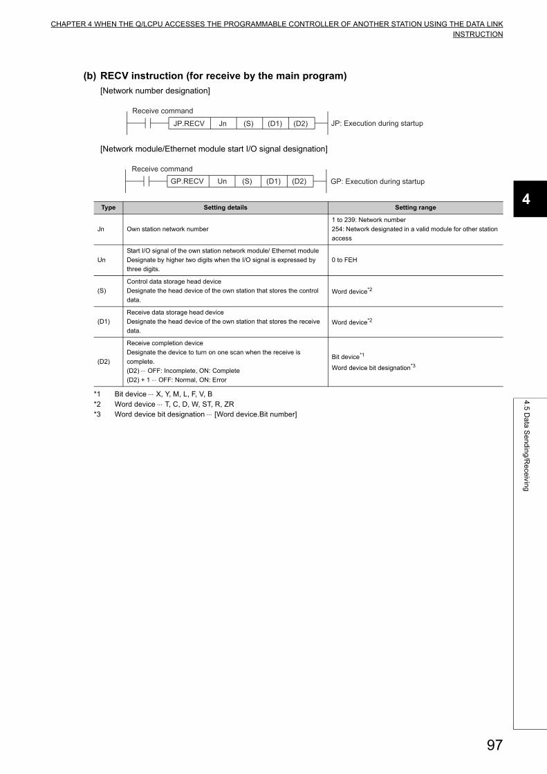
CHAPTER 4 WHEN THE Q/LCPU ACCESSES THE PROGRAMMABLE CONTROLLER OF ANOTHER STATION USING THE DATA LINKINSTRUCTION
4
4.5
Da
ta S
en
din
g/R
ece
iving
(b) RECV instruction (for receive by the main program)
[Network number designation]
[Network module/Ethernet module start I/O signal designation]
*1 Bit device X, Y, M, L, F, V, B*2 Word device T, C, D, W, ST, R, ZR*3 Word device bit designation [Word device.Bit number]
Type Setting details Setting range
Jn Own station network number
1 to 239: Network number
254: Network designated in a valid module for other station
access
Un
Start I/O signal of the own station network module/ Ethernet module
Designate by higher two digits when the I/O signal is expressed by
three digits.
0 to FEH
(S)
Control data storage head device
Designate the head device of the own station that stores the control
data.Word device*2
(D1)
Receive data storage head device
Designate the head device of the own station that stores the receive
data.Word device*2
(D2)
Receive completion device
Designate the device to turn on one scan when the receive is
complete.
(D2) OFF: Incomplete, ON: Complete
(D2) + 1 OFF: Normal, ON: Error
Bit device*1
Word device bit designation*3
JnJP.RECV (S) (D1) (D2)
Receive command
JP: Execution during startup
(S) (D1) (D2)GP.RECV Un GP: Execution during startup
Receive command
97
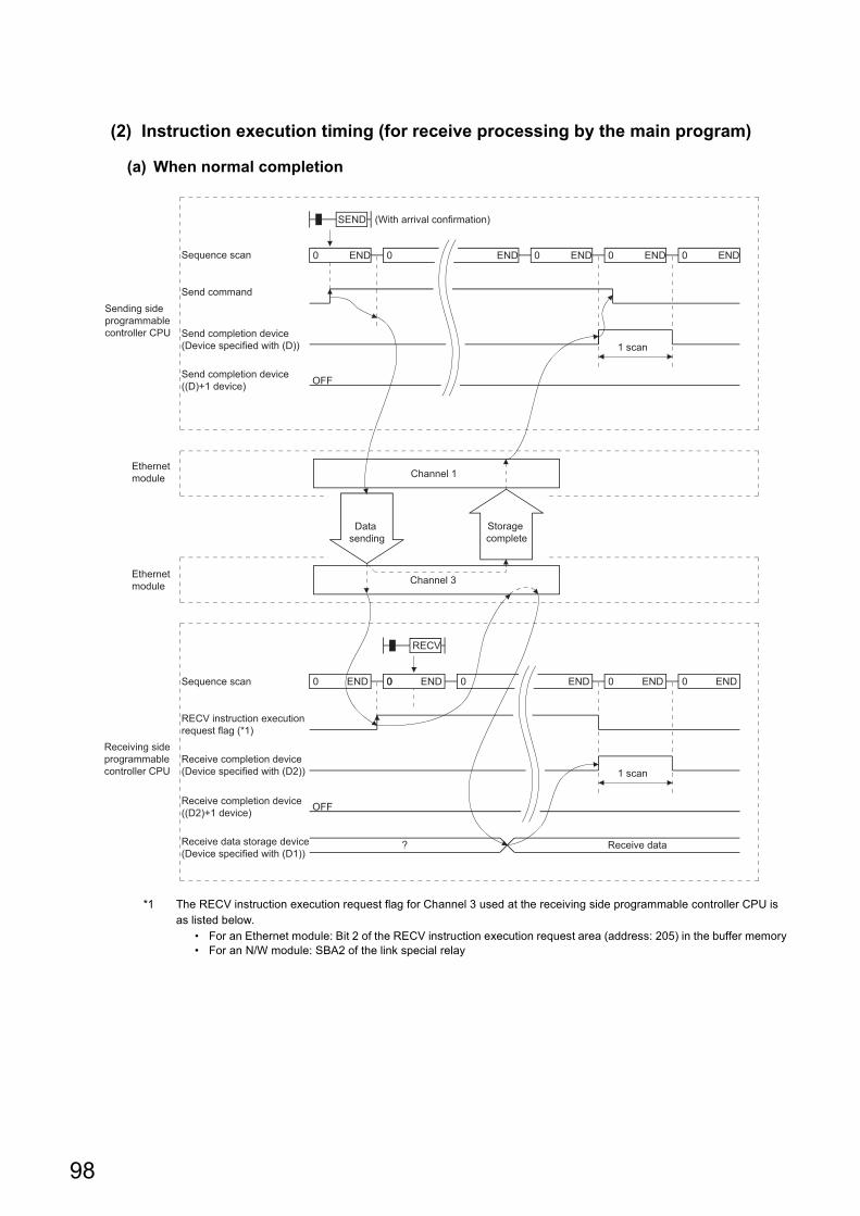
(2) Instruction execution timing (for receive processing by the main program)
(a) When normal completion
*1 The RECV instruction execution request flag for Channel 3 used at the receiving side programmable controller CPU is as listed below.
• For an Ethernet module: Bit 2 of the RECV instruction execution request area (address: 205) in the buffer memory• For an N/W module: SBA2 of the link special relay
Channel 3
Channel 1
Data sending
Storage complete
0 ENDSequence scan 0 END 0 END 0 END 0 END
Send command
SEND (With arrival confirmation)
1 scan
0 ENDSequence scan 0 END 0 END 0 END
RECV
0 END 0
1 scan
? Receive data
OFF
OFF
Sending side programmable controller CPU
Ethernet module
Ethernet module
Receiving side programmable controller CPU
Send completion device (Device specified with (D))
Send completion device ((D)+1 device)
RECV instruction execution request flag (*1)
Receive completion device (Device specified with (D2))
Receive completion device ((D2)+1 device)
Receive data storage device (Device specified with (D1))
98
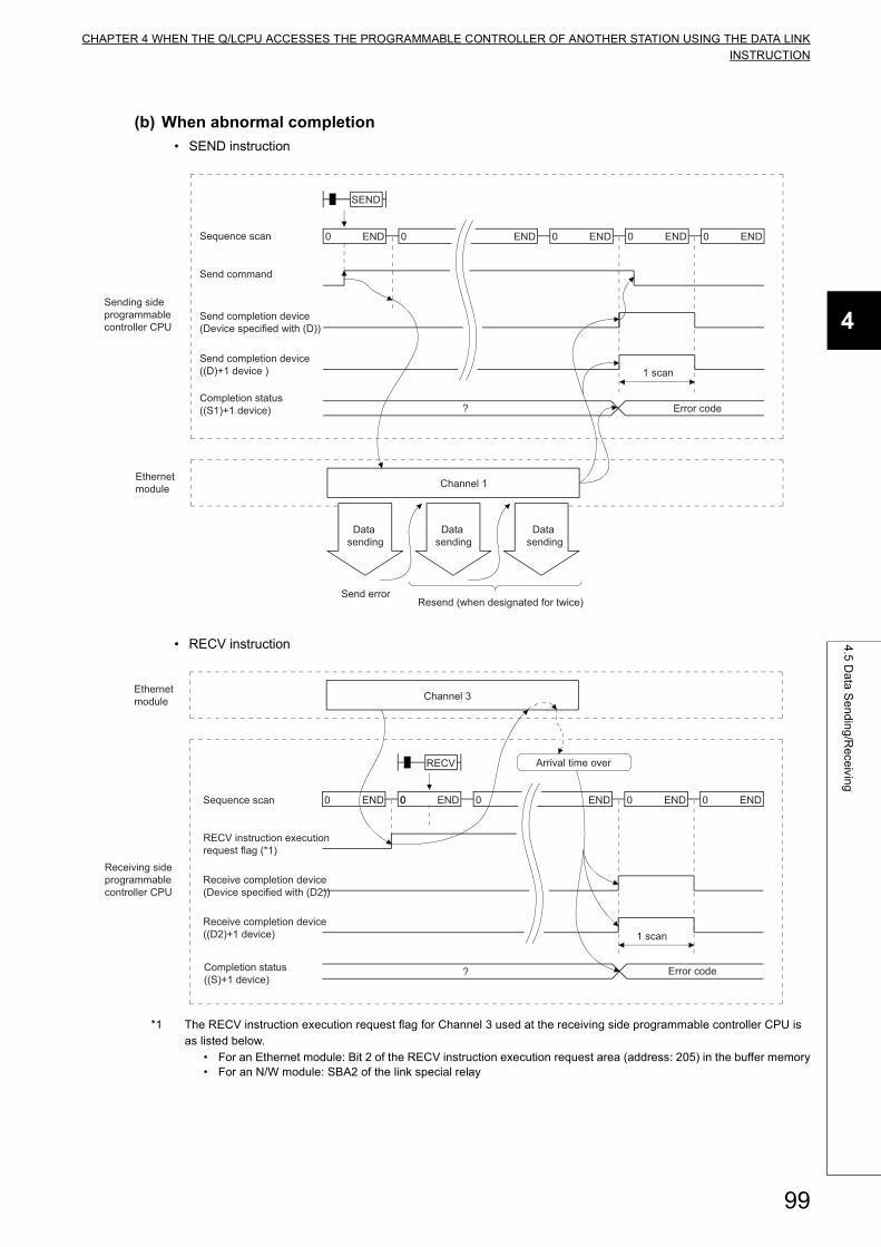
CHAPTER 4 WHEN THE Q/LCPU ACCESSES THE PROGRAMMABLE CONTROLLER OF ANOTHER STATION USING THE DATA LINKINSTRUCTION
4
4.5
Da
ta S
en
din
g/R
ece
iving
(b) When abnormal completion
• SEND instruction
• RECV instruction
*1 The RECV instruction execution request flag for Channel 3 used at the receiving side programmable controller CPU is as listed below.
• For an Ethernet module: Bit 2 of the RECV instruction execution request area (address: 205) in the buffer memory• For an N/W module: SBA2 of the link special relay
Channel 1
Data sending
0 ENDSequence scan 0 END 0 END 0 END 0 END
Send command
SEND
? Error code
1 scan
Data sending
Data sending
Sending side programmable controller CPU
Ethernet module
Send completion device (Device specified with (D))
Send completion device ((D)+1 device )
Completion status ((S1)+1 device)
Send errorResend (when designated for twice)
Channel 3
0 ENDSequence scan 0 END 0 END 0 END
RECV
0 END 0
1 scan
? Error code
Ethernet module
Receiving side programmable controller CPU
RECV instruction execution request flag (*1)
Receive completion device (Device specified with (D2))
Receive completion device ((D2)+1 device)
Completion status ((S)+1 device)
Arrival time over
99
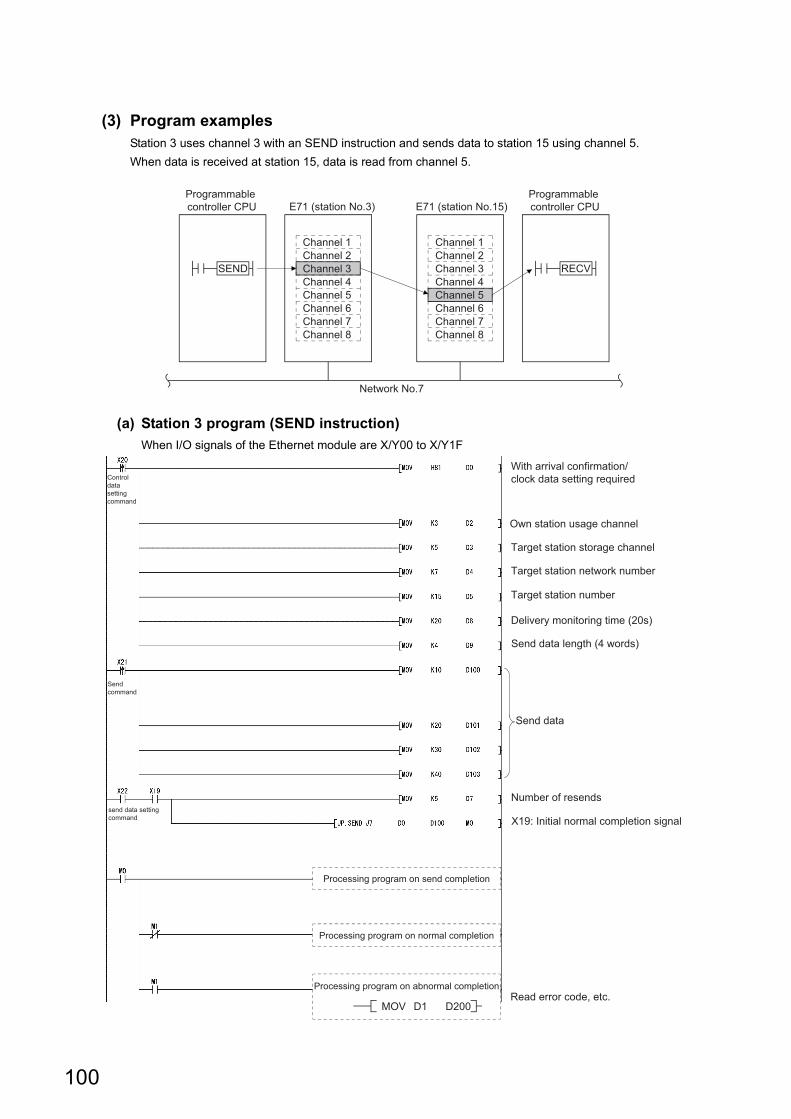
(3) Program examplesStation 3 uses channel 3 with an SEND instruction and sends data to station 15 using channel 5.
When data is received at station 15, data is read from channel 5.
(a) Station 3 program (SEND instruction)
When I/O signals of the Ethernet module are X/Y00 to X/Y1F
SEND
Channel 1Channel 2Channel 3Channel 4Channel 5Channel 6Channel 7Channel 8
Channel 1Channel 2Channel 3Channel 4Channel 5Channel 6Channel 7Channel 8
RECV
Network No.7
Programmable controller CPU E71 (station No.3) E71 (station No.15)
Programmable controller CPU
With arrival confirmation/clock data setting required
Own station usage channel
Target station network number
Send data length (4 words)
Read error code, etc.
Delivery monitoring time (20s)
Target station storage channel
Target station number
Number of resends
Send data
X19: Initial normal completion signal
Processing program on send completion
Processing program on normal completion
Processing program on abnormal completion
MOV D1 D200
Control data setting command
Send command
send data setting command
100
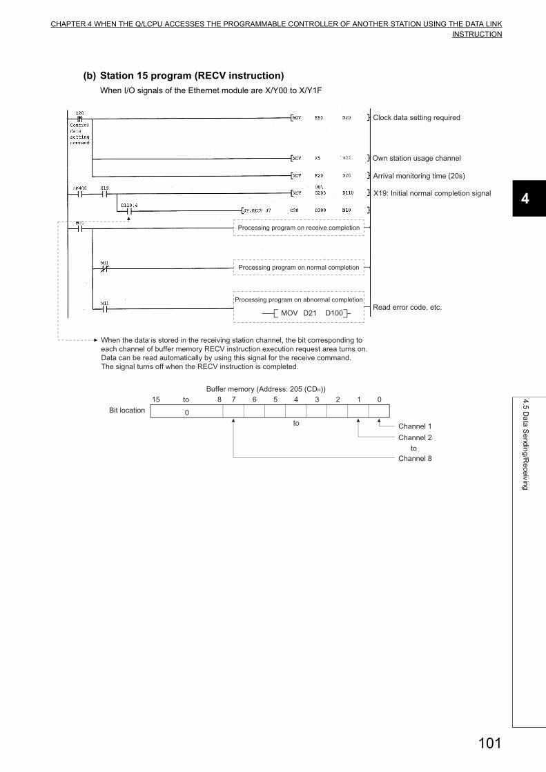
CHAPTER 4 WHEN THE Q/LCPU ACCESSES THE PROGRAMMABLE CONTROLLER OF ANOTHER STATION USING THE DATA LINKINSTRUCTION
4
4.5
Da
ta S
en
din
g/R
ece
iving
(b) Station 15 program (RECV instruction)
When I/O signals of the Ethernet module are X/Y00 to X/Y1F
Clock data setting required
Own station usage channel
Arrival monitoring time (20s)
Read error code, etc.
X19: Initial normal completion signal
When the data is stored in the receiving station channel, the bit corresponding to each channel of buffer memory RECV instruction execution request area turns on. Data can be read automatically by using this signal for the receive command. The signal turns off when the RECV instruction is completed.
Processing program on receive completion
Processing program on normal completion
MOV D21 D100
Processing program on abnormal completion
0
815 7 6 5 4 3 2 1 0
Channel 8
Channel 2Channel 1to
to
toBit location
Buffer memory (Address: 205 (CDH))
101
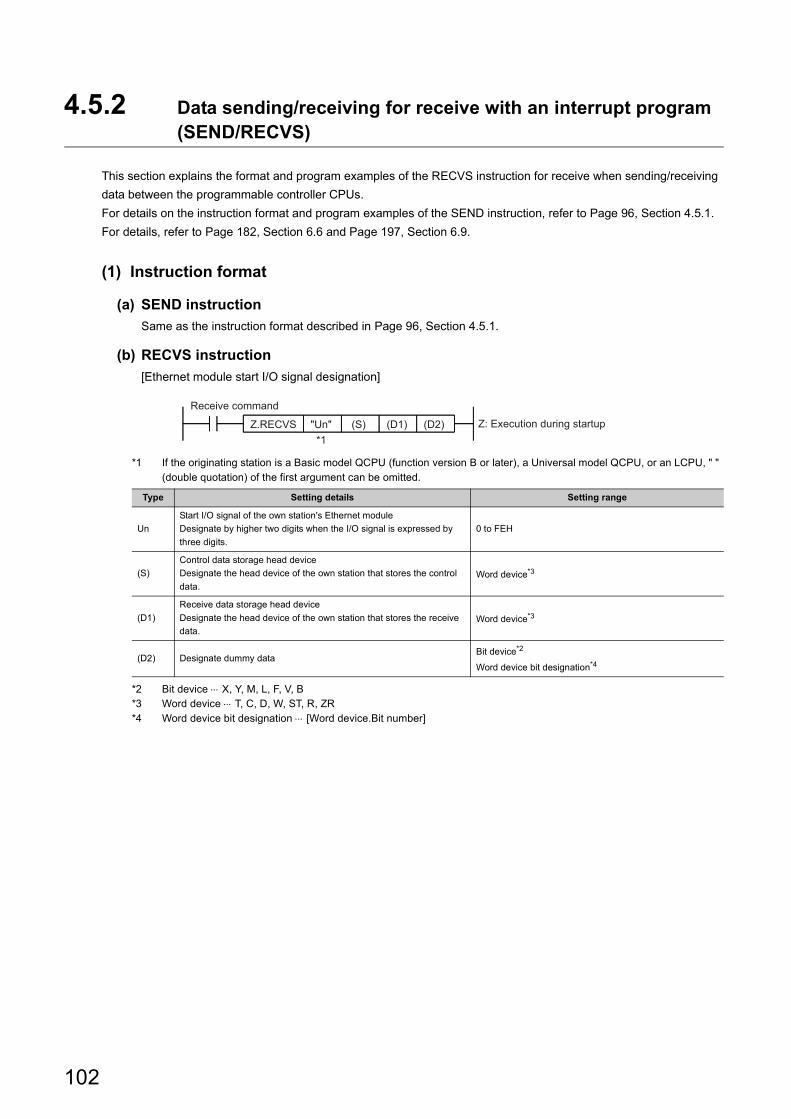
4.5.2 Data sending/receiving for receive with an interrupt program (SEND/RECVS)
This section explains the format and program examples of the RECVS instruction for receive when sending/receiving
data between the programmable controller CPUs.
For details on the instruction format and program examples of the SEND instruction, refer to Page 96, Section 4.5.1.
For details, refer to Page 182, Section 6.6 and Page 197, Section 6.9.
(1) Instruction format
(a) SEND instruction
Same as the instruction format described in Page 96, Section 4.5.1.
(b) RECVS instruction
[Ethernet module start I/O signal designation]
*1 If the originating station is a Basic model QCPU (function version B or later), a Universal model QCPU, or an LCPU, " " (double quotation) of the first argument can be omitted.
*2 Bit device X, Y, M, L, F, V, B*3 Word device T, C, D, W, ST, R, ZR*4 Word device bit designation [Word device.Bit number]
Type Setting details Setting range
Un
Start I/O signal of the own station's Ethernet module
Designate by higher two digits when the I/O signal is expressed by
three digits.
0 to FEH
(S)
Control data storage head device
Designate the head device of the own station that stores the control
data.Word device*3
(D1)
Receive data storage head device
Designate the head device of the own station that stores the receive
data.Word device*3
(D2) Designate dummy dataBit device*2
Word device bit designation*4
Z.RECVS (S) (D1) (D2)"Un" Z: Execution during startup
Receive command
*1
102
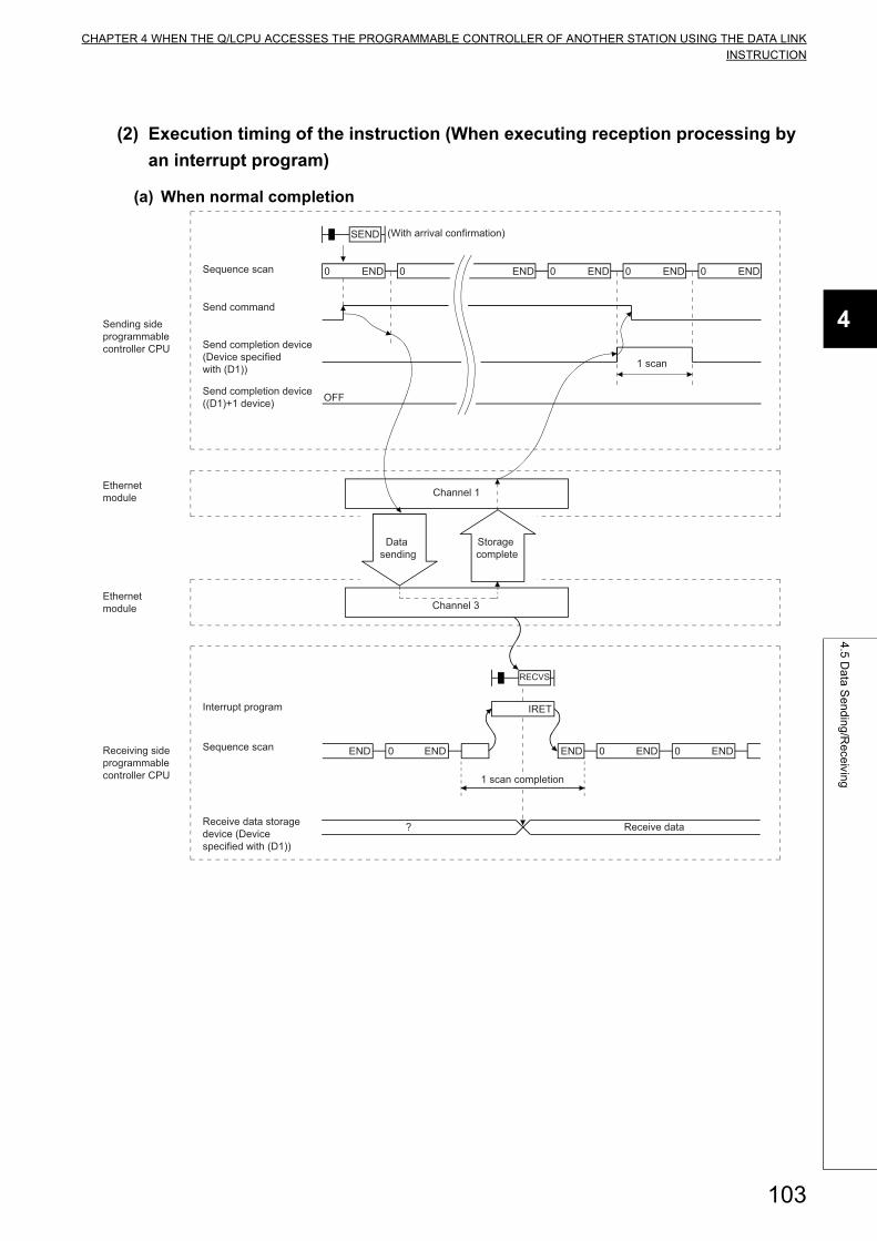
CHAPTER 4 WHEN THE Q/LCPU ACCESSES THE PROGRAMMABLE CONTROLLER OF ANOTHER STATION USING THE DATA LINKINSTRUCTION
4
4.5
Da
ta S
en
din
g/R
ece
iving
(2) Execution timing of the instruction (When executing reception processing by
an interrupt program)
(a) When normal completion
Channel 3
Channel 1
Data sending
Storage complete
0 ENDSequence scan 0 END 0 END 0 END 0 END
Send command
SEND (With arrival confirmation)
1 scan
? Receive data
OFF
Sequence scan 0 END0 END
RECVS
END
IRET
0 ENDEND
Sending side programmable controller CPU
Ethernet module
Ethernet module
Receiving side programmable controller CPU
Send completion device (Device specified with (D1))
Send completion device ((D1)+1 device)
Interrupt program
Receive data storage device (Device specified with (D1))
1 scan completion
103
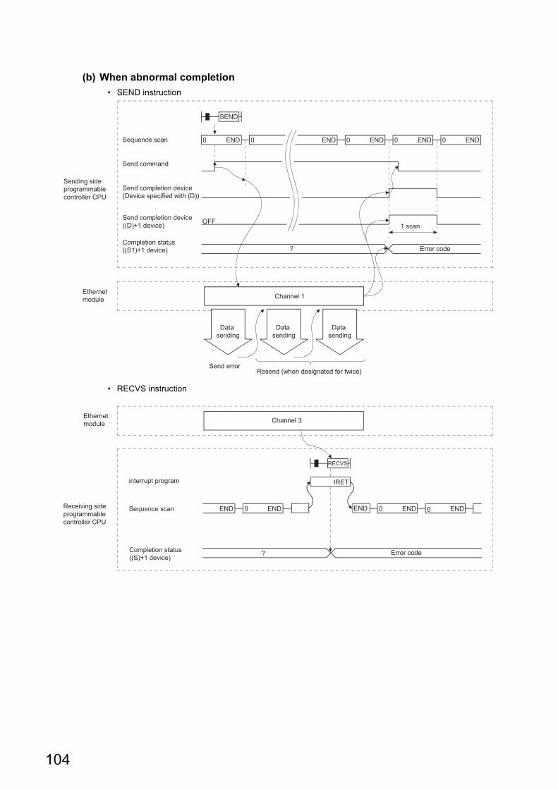
(b) When abnormal completion
• SEND instruction
• RECVS instruction
Channel 1
Data sending
0 ENDSequence scan 0 END 0 END 0 END 0 END
Send command
SEND
? Error code
OFF1 scan
Data sending
Data sending
Sending side programmable controller CPU
Ethernet module
Send completion device (Device specified with (D))
Send completion device ((D)+1 device)
Completion status ((S1)+1 device)
Send errorResend (when designated for twice)
Channel 3
? Error code
Sequence scan 0 END0 END
RECVS
IRET
0 ENDEND END
Ethernet module
Receiving side programmable controller CPU
interrupt program
Completion status ((S)+1 device)
104
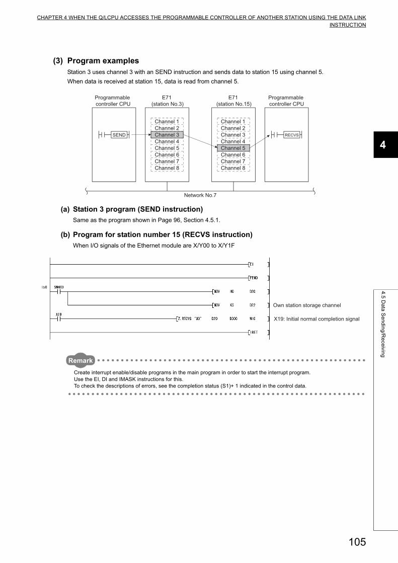
CHAPTER 4 WHEN THE Q/LCPU ACCESSES THE PROGRAMMABLE CONTROLLER OF ANOTHER STATION USING THE DATA LINKINSTRUCTION
4
4.5
Da
ta S
en
din
g/R
ece
iving
(3) Program examplesStation 3 uses channel 3 with an SEND instruction and sends data to station 15 using channel 5.
When data is received at station 15, data is read from channel 5.
(a) Station 3 program (SEND instruction)
Same as the program shown in Page 96, Section 4.5.1.
(b) Program for station number 15 (RECVS instruction)
When I/O signals of the Ethernet module are X/Y00 to X/Y1F
Remark
Create interrupt enable/disable programs in the main program in order to start the interrupt program.Use the EI, DI and IMASK instructions for this.To check the descriptions of errors, see the completion status (S1)+ 1 indicated in the control data.
Programmable controller CPU
Programmable controller CPU
SEND
Channel 1Channel 2Channel 3Channel 4Channel 5Channel 6Channel 7Channel 8
Channel 1Channel 2Channel 3Channel 4Channel 5Channel 6Channel 7Channel 8
Network No.7
E71 (station No.3)
E71 (station No.15)
RECVS
Own station storage channel
X19: Initial normal completion signal
105

4.6 Reading/Writing Word Devices of Other Stations (READ/WRITE)
This section explains the format and program examples of the READ/WRITE instructions that are used to read and
write data of word devices of other stations.
For details, refer to Page 169, Section 6.4, and Page 205, Section 6.10 to Page 215, Section 6.12.
(1) Instruction format
(a) READ/SREAD instructions
[Network number designation]
[Network module/Ethernet module start I/O signal designation]
*1 The SREAD instruction can be programmed without argument (D3).However, in such a case, the operation is identical to the READ instruction.With the SREAD instruction, different operations are available depending on whether (D3) is omitted or not.
*2 When the target station is a Basic model QCPU or safety CPU, the read notification device set as argument (D3) for the target station is ignored. (Same operation as with the READ instruction)
*3 Bit device X, Y, M, L, F, V, B*4 Word device T, C, D, W, ST, R, ZR*5 Word device T, C, D, W, ST, SD, SW, R, ZR*6 Word device bit designation [Word device.Bit number]
Type Setting details Setting range
Jn Own station network number
1 to 239: Network number
254: Network designated in a valid module for other
station access
UnStart I/O signal of the own station network module/ Ethernet module
Designate by higher two digits when the I/O signal is expressed by three digits.0 to FEH
(S1)Control data storage head device
Designate the head device of the own station that stores the control data.Word device*4
(S2)Read data storage head device (target station)
Designate the head device of the target station that stores the data to read.Word device*5
(D1)Read data storage head device (own station)
Designate the head device of the own station that stores the data to read.Word device*4
(D2)
Read completion device (own station)
Designate device that is turned on for one scan by the read completion
(D2) OFF: Incomplete, ON: Complete
(D2) + 1 OFF: Normal, ON: Error
Bit device*3
Word device bit designation*6
(D3)
Read notify device (target station)
Designate the device of the target station to turn on one scan when the read is
complete.
(Can recognize data of target station has been read from other station.)
(D3) OFF: Incomplete, ON: Complete
Bit device*3
Word device bit designation*6
JP.SREAD Jn
JP.READ Jn (S1) (S2) (D1) (D2)
(S2) (D1) (D2) (D3)(S1) JP: Execution during startup
JP: Execution during startup
Read command
Read command
*1*2
GP.SREAD Un
GP.READ Un (S1) (S2) (D1) (D2)
(S1) (S2) (D1) (D2) (D3) GP: Execution during startup
GP: Execution during startup
Read command
Read command
*1*2
106
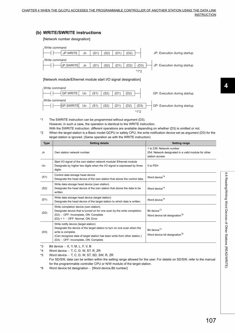
CHAPTER 4 WHEN THE Q/LCPU ACCESSES THE PROGRAMMABLE CONTROLLER OF ANOTHER STATION USING THE DATA LINKINSTRUCTION
4
4.6
Re
ad
ing
/Writin
g W
ord
De
vices o
f Oth
er S
tatio
ns (R
EA
D/W
RIT
E)
(b) WRITE/SWRITE instructions
[Network number designation]
[Network module/Ethernet module start I/O signal designation]
*1 The SWRITE instruction can be programmed without argument (D3).However, in such a case, the operation is identical to the WRITE instruction.With the SWRITE instruction, different operations are available depending on whether (D3) is omitted or not.
*2 When the target station is a Basic model QCPU or safety CPU, the write notification device set as argument (D3) for the target station is ignored. (Same operation as with the WRITE instruction)
*3 Bit device X, Y, M, L, F, V, B*4 Word device T, C, D, W, ST, R, ZR*5 Word device T, C, D, W, ST, SD, SW, R, ZR
For SD/SW, data can be written within the setting range allowed for the user. For details on SD/SW, refer to the manual for the programmable controller CPU or N/W module of the target station.
*6 Word device bit designation [Word device.Bit number]
Type Setting details Setting range
Jn Own station network number
1 to 239: Network number
254: Network designated in a valid module for other
station access
Un
Start I/O signal of the own station network module/ Ethernet module
Designate by higher two digits when the I/O signal is expressed by three
digits.
0 to FEH
(S1)Control data storage head device
Designate the head device of the own station that stores the control data.Word device*4
(S2)
Write data storage head device (own station)
Designate the head device of the own station that stores the data to be
written.Word device*4
(D1)Write data storage head device (target station)
Designate the head device of the target station to which data is written.Word device*5
(D2)
Write completion device (own station)
Designate device that is turned on for one scan by the write completion.
(D2) OFF: Incomplete, ON: Complete
(D2) + 1 OFF: Normal, ON: Error
Bit device*3
Word device bit designation*6
(D3)
Write notify device (target station)
Designate the device of the target station to turn on one scan when the
write is complete.
(Can recognize data of target station has been write from other station.)
(D3) OFF: Incomplete, ON: Complete
Bit device*3
Word device bit designation*6
JP.SWRITE Jn
JP.WRITE Jn (S1) (S2) (D1) (D2)
(S1) (S2) (D1) (D2) (D3) JP: Execution during startup
JP: Execution during startup
Write command
Write command
*1*2
GP.SWRITE Un
GP.WRITE Un (S1) (S2) (D1) (D2)
(S1) (S2) (D1) (D2) (D3) GP: Execution during startup
GP: Execution during startup
Write command
Write command
*1*2
107
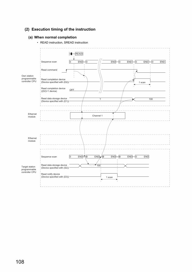
(2) Execution timing of the instruction
(a) When normal completion
• READ instruction, SREAD instruction
0 ENDSequence scan 0 END 0 END 0 END 0 END
READ
1 scan
0 ENDSequence scan 0 0 END0 END
1 scan
100
OFF
? 100
00 END 00 END
Own station programmable controller CPU
Ethernet module
Ethernet module
Target station programmable controller CPU
Read command
Read completion device (Device specified with (D2))
Read completion device ((D2)+1 device)
Read data storage device (Device specified with (D1))
Read data storage device (Device specified with (S2))
Read notify device (Device specified with (D3))
Channel 1
108
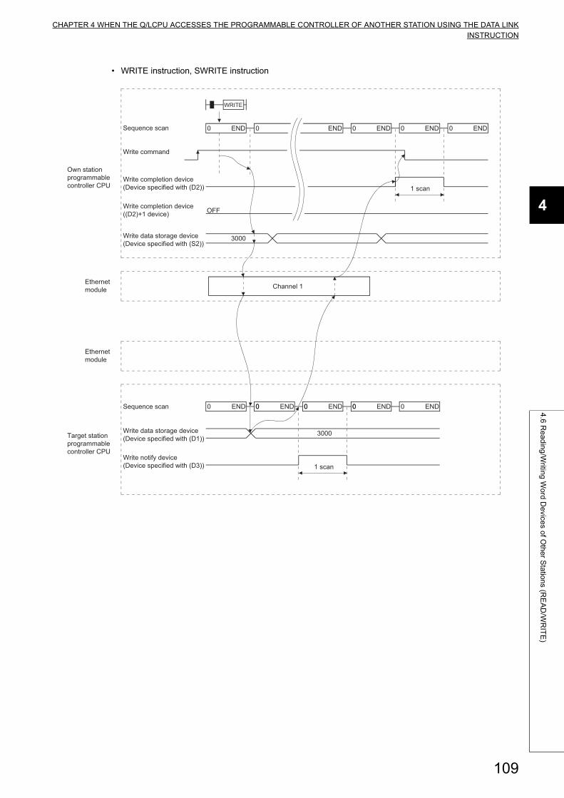
CHAPTER 4 WHEN THE Q/LCPU ACCESSES THE PROGRAMMABLE CONTROLLER OF ANOTHER STATION USING THE DATA LINKINSTRUCTION
4
4.6
Re
ad
ing
/Writin
g W
ord
De
vices o
f Oth
er S
tatio
ns (R
EA
D/W
RIT
E)
• WRITE instruction, SWRITE instruction
Channel 1
0 ENDSequence scan 0 END 0 END 0 END 0 END
WRITE
1 scan
0 ENDSequence scan 0 0 END0 END
1 scan
3000
OFF
3000
00 END 00 END
Own station programmable controller CPU
Ethernet module
Ethernet module
Target station programmable controller CPU
Write command
Write completion device (Device specified with (D2))
Write completion device ((D2)+1 device)
Write data storage device (Device specified with (S2))
Write data storage device (Device specified with (D1))
Write notify device (Device specified with (D3))
109
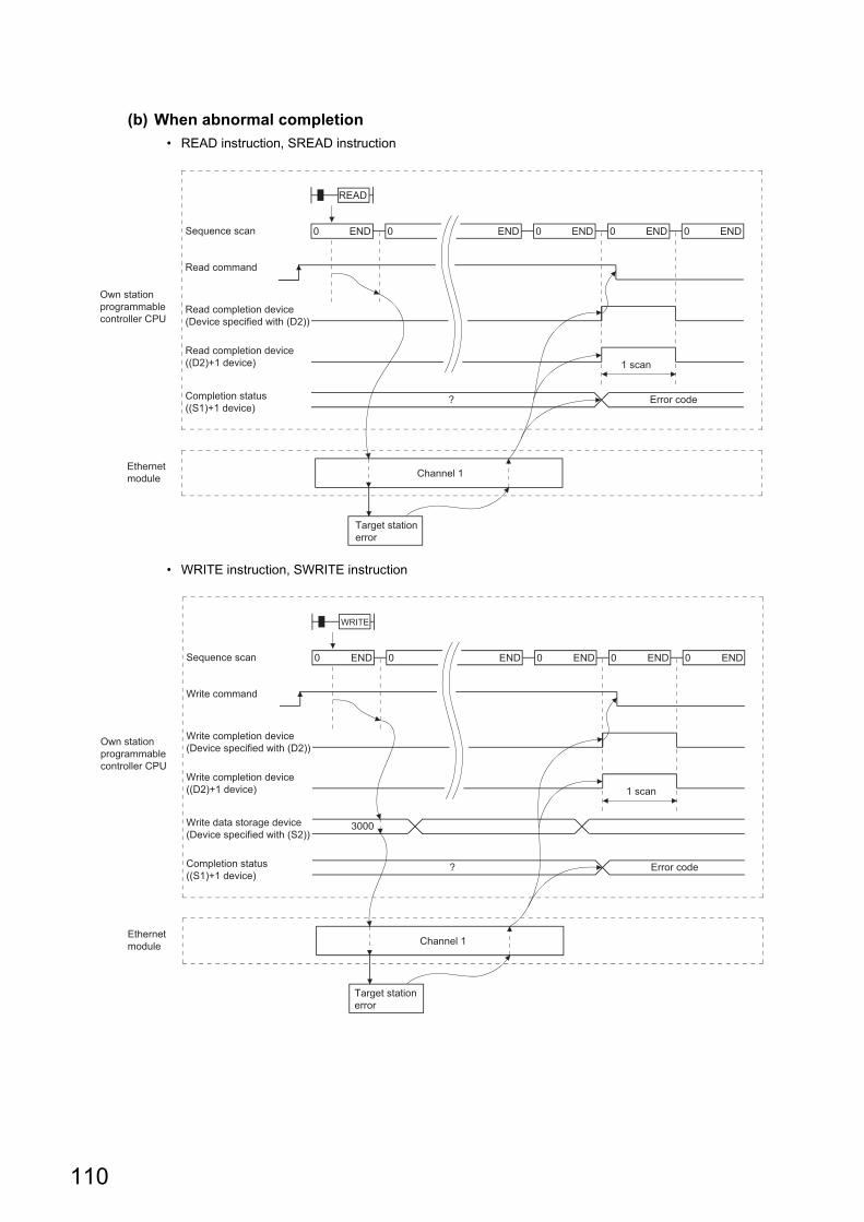
(b) When abnormal completion
• READ instruction, SREAD instruction
• WRITE instruction, SWRITE instruction
Channel 1
0 ENDSequence scan 0 END 0 END 0 END 0 END
READ
1 scan
? Error code
Target station error
Own station programmable controller CPU
Ethernet module
Read command
Read completion device (Device specified with (D2))
Read completion device ((D2)+1 device)
Completion status ((S1)+1 device)
Channel 1
0 ENDSequence scan 0 END 0 END 0 END 0 END
WRITE
1 scan
? Error code
Target station error
3000
Own station programmable controller CPU
Ethernet module
Write command
Write completion device (Device specified with (D2))
Write completion device ((D2)+1 device)
Write data storage device (Device specified with (S2))
Completion status ((S1)+1 device)
110
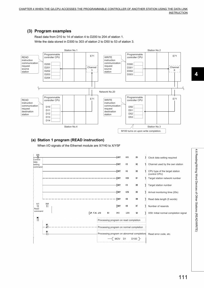
CHAPTER 4 WHEN THE Q/LCPU ACCESSES THE PROGRAMMABLE CONTROLLER OF ANOTHER STATION USING THE DATA LINKINSTRUCTION
4
4.6
Re
ad
ing
/Writin
g W
ord
De
vices o
f Oth
er S
tatio
ns (R
EA
D/W
RIT
E)
(3) Program examplesRead data from D10 to 14 of station 4 to D200 to 204 of station 1.
Write the data stored in D300 to 303 of station 2 to D50 to 53 of station 3.
(a) Station 1 program (READ instruction)
When I/O signals of the Ethernet module are X/Y40 to X/Y5F
Programmable controller CPU E71
D300D301D302D303
Programmable controller CPU E71
D200D201D202D203D204
Programmable controller CPU E71
D50D51D52D53
Programmable controller CPU
D10D11D12D13D14
E71
Station No.1
Station No.4
Station No.2
Station No.3
M100 turns on upon write completion.
Network No.20
READ instruction communication request sourcestation
READ instruction communication request destination station
Channel3
WRITE instruction communication request source station
WRITE instruction communication request destination station
Channel6
Clock data setting required
Channel used by the own station
Read error code, etc.
Arrival monitoring time (20s)
Target station number
Number of resends
Processing program on abnormal completion
MOV D1 D100
Control data setting command
CPU type of the target station (control CPU)
Target station network number
Read data length (5 words)
X59: Initial normal completion signal
Processing program on normal completion
Processing program on read completion
Read command
111
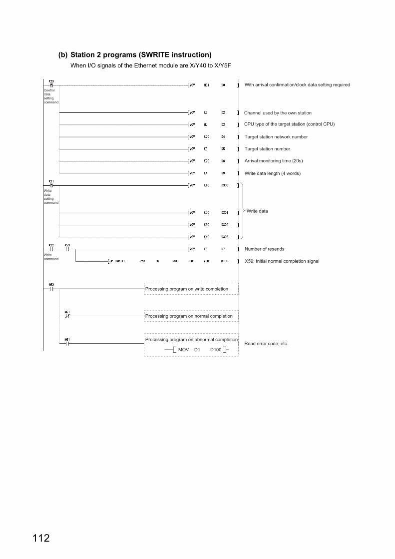
(b) Station 2 programs (SWRITE instruction)
When I/O signals of the Ethernet module are X/Y40 to X/Y5F
Channel used by the own station
Target station network number
Write data length (4 words)
Read error code, etc.
Arrival monitoring time (20s)
Target station number
Number of resends
Write data
Processing program on write completion
Processing program on normal completion
Processing program on abnormal completion
MOV D1 D100
Control data setting command
Write data setting command
Write command
With arrival confirmation/clock data setting required
CPU type of the target station (control CPU)
X59: Initial normal completion signal
112
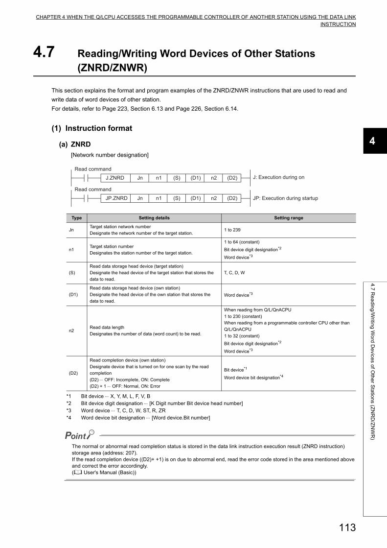
CHAPTER 4 WHEN THE Q/LCPU ACCESSES THE PROGRAMMABLE CONTROLLER OF ANOTHER STATION USING THE DATA LINKINSTRUCTION
4
4.7
Re
ad
ing
/Writin
g W
ord
De
vices o
f Oth
er S
tatio
ns (Z
NR
D/Z
NW
R)
4.7 Reading/Writing Word Devices of Other Stations (ZNRD/ZNWR)
This section explains the format and program examples of the ZNRD/ZNWR instructions that are used to read and
write data of word devices of other station.
For details, refer to Page 223, Section 6.13 and Page 226, Section 6.14.
(1) Instruction format
(a) ZNRD
[Network number designation]
*1 Bit device X, Y, M, L, F, V, B*2 Bit device digit designation [K Digit number Bit device head number]*3 Word device T, C, D, W, ST, R, ZR*4 Word device bit designation [Word device.Bit number]
The normal or abnormal read completion status is stored in the data link instruction execution result (ZNRD instruction) storage area (address: 207).If the read completion device ((D2)+ +1) is on due to abnormal end, read the error code stored in the area mentioned above and correct the error accordingly.( User's Manual (Basic))
Type Setting details Setting range
JnTarget station network number
Designate the network number of the target station.1 to 239
n1Target station number
Designates the station number of the target station.
1 to 64 (constant)
Bit device digit designation*2
Word device*3
(S)
Read data storage head device (target station)
Designate the head device of the target station that stores the
data to read.
T, C, D, W
(D1)
Read data storage head device (own station)
Designate the head device of the own station that stores the
data to read.Word device*3
n2Read data length
Designates the number of data (word count) to be read.
When reading from Q/L/QnACPU
1 to 230 (constant)
When reading from a programmable controller CPU other than
Q/L/QnACPU
1 to 32 (constant)
Bit device digit designation*2
Word device*3
(D2)
Read completion device (own station)
Designate device that is turned on for one scan by the read
completion
(D2) OFF: Incomplete, ON: Complete
(D2) + 1 OFF: Normal, ON: Error
Bit device*1
Word device bit designation*4
J.ZNRD Jn
JP.ZNRD Jn
n1
n1
n2
n2
(S) (D1) (D2)
(S) (D1) (D2)
J: Execution during onRead command
JP: Execution during startup
Read command
113
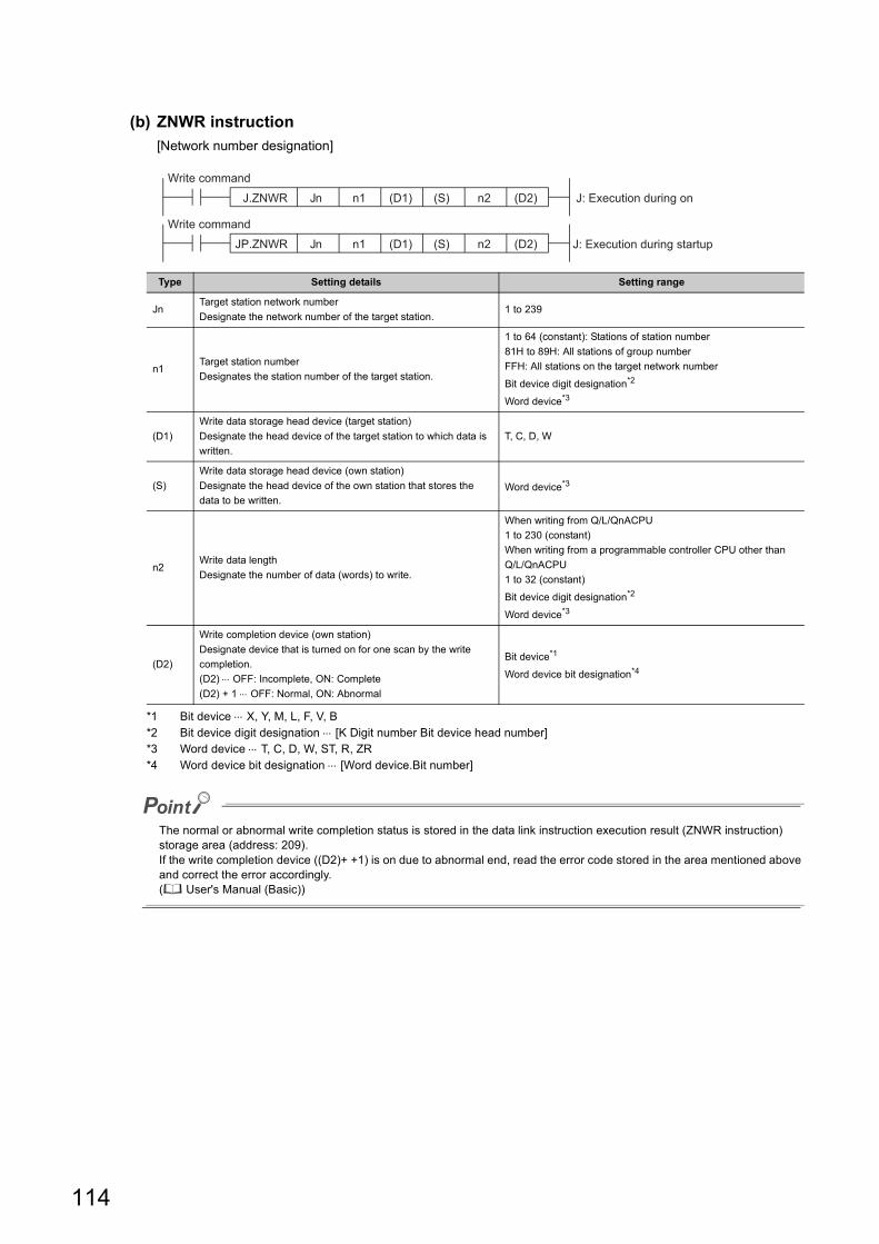
(b) ZNWR instruction
[Network number designation]
*1 Bit device X, Y, M, L, F, V, B*2 Bit device digit designation [K Digit number Bit device head number]*3 Word device T, C, D, W, ST, R, ZR*4 Word device bit designation [Word device.Bit number]
The normal or abnormal write completion status is stored in the data link instruction execution result (ZNWR instruction) storage area (address: 209).If the write completion device ((D2)+ +1) is on due to abnormal end, read the error code stored in the area mentioned above and correct the error accordingly.( User's Manual (Basic))
Type Setting details Setting range
JnTarget station network number
Designate the network number of the target station.1 to 239
n1Target station number
Designates the station number of the target station.
1 to 64 (constant): Stations of station number
81H to 89H: All stations of group number
FFH: All stations on the target network number
Bit device digit designation*2
Word device*3
(D1)
Write data storage head device (target station)
Designate the head device of the target station to which data is
written.
T, C, D, W
(S)
Write data storage head device (own station)
Designate the head device of the own station that stores the
data to be written.Word device*3
n2Write data length
Designate the number of data (words) to write.
When writing from Q/L/QnACPU
1 to 230 (constant)
When writing from a programmable controller CPU other than
Q/L/QnACPU
1 to 32 (constant)
Bit device digit designation*2
Word device*3
(D2)
Write completion device (own station)
Designate device that is turned on for one scan by the write
completion.
(D2) OFF: Incomplete, ON: Complete
(D2) + 1 OFF: Normal, ON: Abnormal
Bit device*1
Word device bit designation*4
J.ZNWR Jn
JP.ZNWR Jn
n1
n1
n2
n2
(D1) (S) (D2)
(D1) (S) (D2)
J: Execution during on
Write command
J: Execution during startup
Write command
114
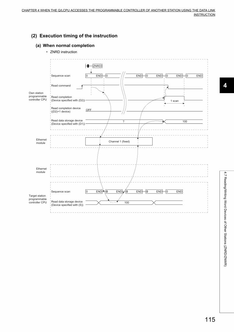
CHAPTER 4 WHEN THE Q/LCPU ACCESSES THE PROGRAMMABLE CONTROLLER OF ANOTHER STATION USING THE DATA LINKINSTRUCTION
4
4.7
Re
ad
ing
/Writin
g W
ord
De
vices o
f Oth
er S
tatio
ns (Z
NR
D/Z
NW
R)
(2) Execution timing of the instruction
(a) When normal completion
• ZNRD instruction
0 ENDSequence scan 0 END 0 END 0 END 0 END
1 scan
0 ENDSequence scan 0 0 END0 END
100
OFF
?
00 END 00 END
100
Own station programmable controller CPU
Ethernet module
Ethernet module
Target station programmable controller CPU
Read command
Read completion (Device specified with (D2))
Read completion device ((D2)+1 device)
Read data storage device (Device specified with (D1))
Read data storage device (Device specified with (S))
Channel 1 (fixed)
ZNRD
115
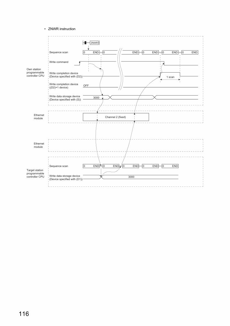
• ZNWR instruction
0 ENDSequence scan 0 END 0 END 0 END 0 END
ZNWR
1 scan
0 ENDSequence scan 0 0 ENDEND
3000
OFF
3000
0 END 0 END
Own station programmable controller CPU
Ethernet module
Ethernet module
Target station programmable controller CPU
Write command
Write completion device (Device specified with (D2))
Write completion device ((D2)+1 device)
Write data storage device (Device specified with (S))
Write data storage device (Device specified with (D1))
Channel 2 (fixed)
116
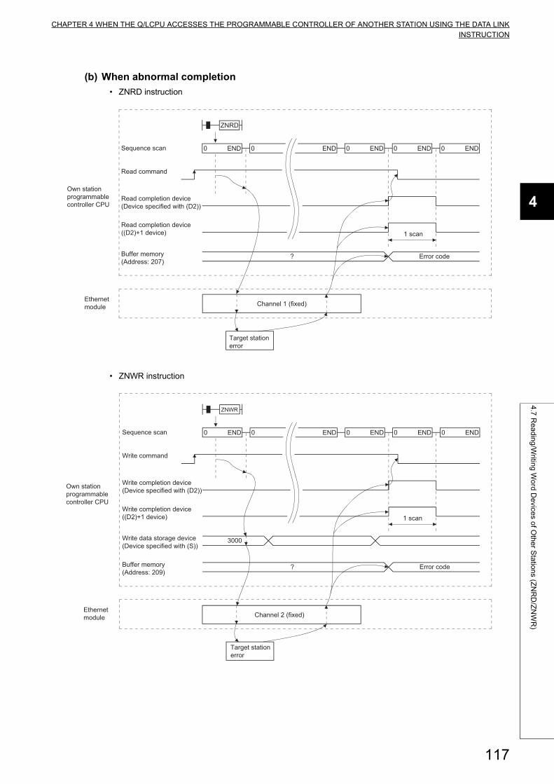
CHAPTER 4 WHEN THE Q/LCPU ACCESSES THE PROGRAMMABLE CONTROLLER OF ANOTHER STATION USING THE DATA LINKINSTRUCTION
4
4.7
Re
ad
ing
/Writin
g W
ord
De
vices o
f Oth
er S
tatio
ns (Z
NR
D/Z
NW
R)
(b) When abnormal completion
• ZNRD instruction
• ZNWR instruction
0 ENDSequence scan 0 END 0 END 0 END 0 END
ZNRD
1 scan
? Error code
Target station error
Own station programmable controller CPU
Ethernet module
Read command
Read completion device (Device specified with (D2))
Read completion device ((D2)+1 device)
Buffer memory (Address: 207)
Channel 1 (fixed)
0 ENDSequence scan 0 END 0 END 0 END 0 END
ZNWR
1 scan
? Error code
Target station error
3000
Own station programmable controller CPU
Ethernet module
Write command
Write completion device (Device specified with (D2))
Write completion device ((D2)+1 device)
Write data storage device (Device specified with (S))
Buffer memory (Address: 209)
Channel 2 (fixed)
117
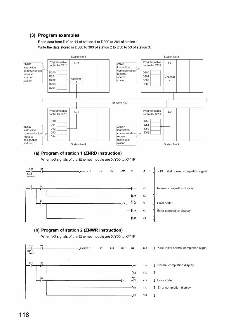
(3) Program examplesRead data from D10 to 14 of station 4 to D200 to 204 of station 1.
Write the data stored in D300 to 303 of station 2 to D50 to 53 of station 3.
(a) Program of station 1 (ZNRD instruction)
When I/O signals of the Ethernet module are X/Y00 to X/Y1F
(b) Program of station 2 (ZNWR instruction)
When I/O signals of the Ethernet module are X/Y00 to X/Y1F
Station No.1 Station No.2
E71
D300D301D302D303
D200D201D202D203D204
E71
D50D51D52D53
D10D11D12D13D14
E71
Station No.4 Station No.3
Network No.1
E71ZNRD instruction communication request source station
ZNRD instruction communication request designation station
ZNWR instruction communication request source station
ZNWR instruction communication request destination station
Programmable controller CPU
Programmable controller CPU
Programmable controller CPU
Programmable controller CPU
Channel1
Channel2
Error completion display
Error code
Normal completion display
X19: Initial normal completion signal
X19: Initial normal completion signal
Error completion display
Error code
Normal completion display
118

CHAPTER 4 WHEN THE Q/LCPU ACCESSES THE PROGRAMMABLE CONTROLLER OF ANOTHER STATION USING THE DATA LINKINSTRUCTION
4
4.8
Re
ad
ing
/Writin
g C
lock D
ata
, Re
mo
te R
UN
/Re
mo
te S
TO
P (R
EQ
)
4.8 Reading/Writing Clock Data, Remote RUN/Remote STOP (REQ)
This section explains the format and program examples of the REQ instruction that is used to read/write clock data and
remote RUN/remote STOP of the Q/L/QnACPU of other stations.
For details, refer to Page 186, Section 6.7 and Page 194, Section 6.8.
(1) Instruction format[Network number designation]
[Network module/Ethernet module start I/O signal designation]
*1 Bit device X, Y, M, L, F, V, B*2 Word device T, C, D, W, ST, R, ZR*3 Word device bit designation [Word device.Bit number]
Type Setting details Setting range
Jn Own station network number
1 to 239: Network number
254: Network designated in a valid module for other station
access
Un
Start I/O signal of the own station network module/ Ethernet module
Designate by higher two digits when the I/O signal is expressed by
three digits.
0 to FEH
(S1)
Control data storage head device
Designate the head device of the own station that stores the control
data.Word device*2
(S2)
Request data storage head device (own station)
Designate the head device of the own station that stores the request
data.Word device*2
(D1)
Response data storage head device (own station)
Designate the head device of the own station that stores the response
data.Word device*2
(D2)
Execution completion device (own station)
Designate the device of the own station to turn on one scan when the
execution is complete.
(D2) OFF: Incomplete, ON: Complete
(D2) + 1 OFF: Normal, ON: Error
Bit device*1
Word device bit designation*3
J.REQ Jn
JP.REQ Jn
(S1) (S2) (D1) (D2)
(S1) (S2) (D1) (D2) JP: Execution during startup
J: Execution during on
Execution command
Execution command
G.REQ Un
GP.REQ Un
(S1) (S2) (D1) (D2)
(S1) (S2) (D1) (D2) GP: Execution during startup
G: Execution during on
Execution command
Execution command
119
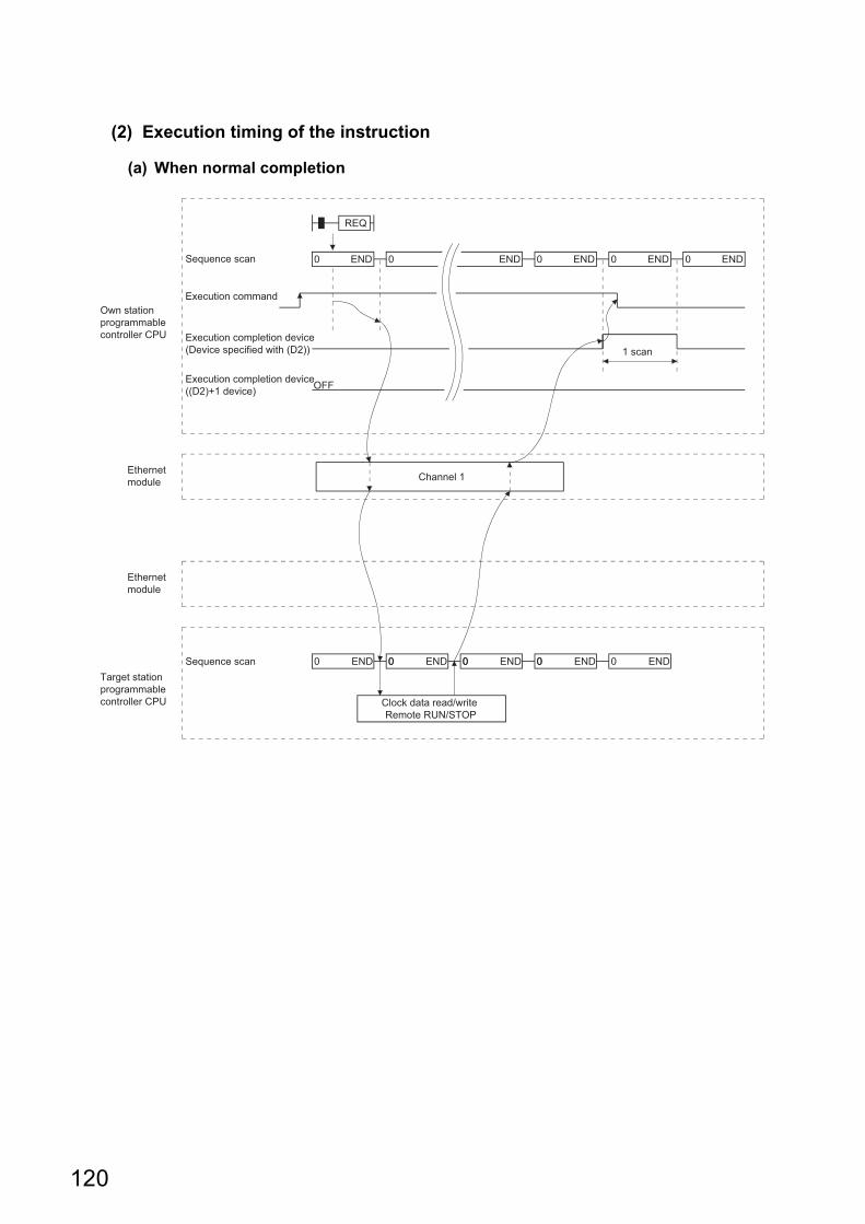
(2) Execution timing of the instruction
(a) When normal completion
Channel 1
0 ENDSequence scan 0 END 0 END 0 END 0 END
1 scan
0 ENDSequence scan 0 0 END0 END
OFF
00 END 00 END
Own station programmable controller CPU
Ethernet module
Ethernet module
Target station programmable controller CPU
Execution command
Execution completion device (Device specified with (D2))
Execution completion device ((D2)+1 device)
Clock data read/write Remote RUN/STOP
REQ
120
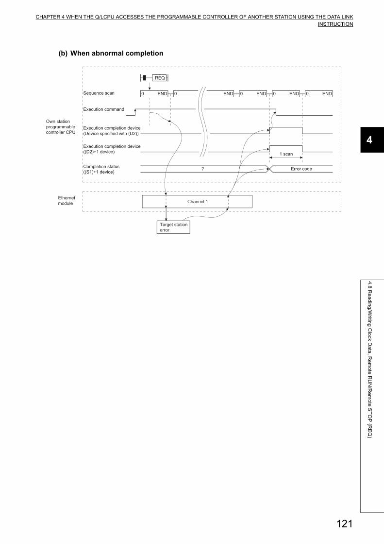
CHAPTER 4 WHEN THE Q/LCPU ACCESSES THE PROGRAMMABLE CONTROLLER OF ANOTHER STATION USING THE DATA LINKINSTRUCTION
4
4.8
Re
ad
ing
/Writin
g C
lock D
ata
, Re
mo
te R
UN
/Re
mo
te S
TO
P (R
EQ
)
(b) When abnormal completion
Channel 1
0 ENDSequence scan 0 END 0 END 0 END 0 END
1 scan
? Error code
Target station error
Own station programmable controller CPU
Ethernet module
Execution command
Execution completion device (Device specified with (D2))
Execution completion device ((D2)+1 device)
Completion status ((S1)+1 device)
REQ
121
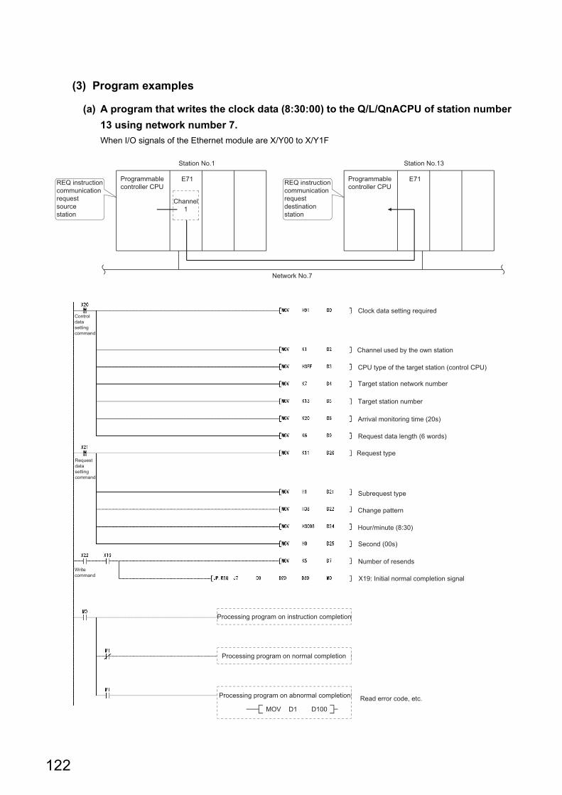
(3) Program examples
(a) A program that writes the clock data (8:30:00) to the Q/L/QnACPU of station number
13 using network number 7.
When I/O signals of the Ethernet module are X/Y00 to X/Y1F
Station No.1 Station No.13
Programmable controller CPU
Programmable controller CPU
E71 E71
Network No.7
REQ instruction communication request source station
Channel1
REQ instruction communication request destination station
Clock data setting required
Channel used by the own station
Request data length (6 words)
Read error code, etc.
Arrival monitoring time (20s)
Target station number
Number of resends
Request type
Subrequest type
Target station network number
Processing program on instruction completion
Processing program on normal completion
Processing program on abnormal completion
MOV D1 D100
Change pattern
Control data setting command
Request data setting command
Write command
CPU type of the target station (control CPU)
Hour/minute (8:30)
Second (00s)
X19: Initial normal completion signal
122
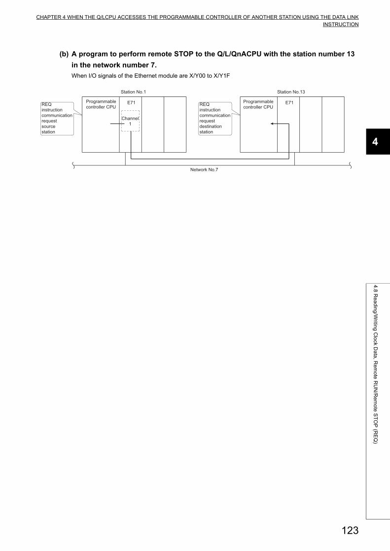
CHAPTER 4 WHEN THE Q/LCPU ACCESSES THE PROGRAMMABLE CONTROLLER OF ANOTHER STATION USING THE DATA LINKINSTRUCTION
4
4.8
Re
ad
ing
/Writin
g C
lock D
ata
, Re
mo
te R
UN
/Re
mo
te S
TO
P (R
EQ
)
(b) A program to perform remote STOP to the Q/L/QnACPU with the station number 13
in the network number 7.
When I/O signals of the Ethernet module are X/Y00 to X/Y1F
Station No.1 Station No.13
Programmable controller CPU
E71 Programmable controller CPU
E71
Network No.7
REQ instruction communication request source station
Channel1
REQ instruction communication request destination station
123
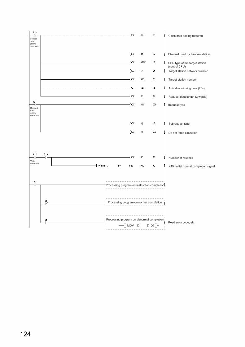
Clock data setting required
Channel used by the own station
Request data length (3 words)
Read error code, etc.
Arrival monitoring time (20s)
Target station number
Request type
Subrequest type
Target station network number
Processing program on instruction completion
Processing program on normal completion
Processing program on abnormal completion
MOV D1 D100
Do not force execution.
Control data setting command
Request data setting command
Write command
CPU type of the target station (control CPU)
Number of resends
X19: Initial normal completion signal
124
CHAPTER 4 WHEN THE Q/LCPU ACCESSES THE PROGRAMMABLE CONTROLLER OF ANOTHER STATION USING THE DATA LINKINSTRUCTION
4
4.9
Erro
r Co
de
s for D
ata
Lin
k Instru
ction
s
4.9 Error Codes for Data Link Instructions
For the error codes that are returned when the execution results of data link instructions in this chapter end abnormally,
refer to the User's Manual (Basic).
The error code for data link instruction is stored in the Ethernet module error log area and the following area:
• SEND, RECV (RECVS), READ (SREAD), WRITE (SWRITE), REQ: Control data completion status ((S1) +
1)
• ZNRD: Buffer memory (Address 207)
• ZNWR: Buffer memory (Address 209)
125
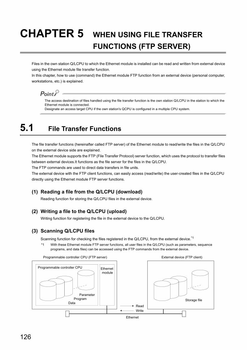
CHAPTER 5 WHEN USING FILE TRANSFER
FUNCTIONS (FTP SERVER)
Files in the own station Q/LCPU to which the Ethernet module is installed can be read and written from external device
using the Ethernet module file transfer function.
In this chapter, how to use (command) the Ethernet module FTP function from an external device (personal computer,
workstations, etc.) is explained.
The access destination of files handled using the file transfer function is the own station Q/LCPU in the station to which the Ethernet module is connected.Designate an access target CPU if the own station's QCPU is configured in a multiple CPU system.
5.1 File Transfer Functions
The file transfer functions (hereinafter called FTP server) of the Ethernet module to read/write the files in the Q/LCPU
on the external device side are explained.
The Ethernet module supports the FTP (File Transfer Protocol) server function, which uses the protocol to transfer files
between external devices.It functions as the file server for the files in the Q/LCPU.
The FTP commands are used to direct data transfers in file units.
The external device with the FTP client functions, can easily access (read/write) the user-created files in the Q/LCPU
directly using the Ethernet module FTP server functions.
(1) Reading a file from the Q/LCPU (download)Reading function for storing the Q/LCPU files in the external device.
(2) Writing a file to the Q/LCPU (upload)Writing function for registering the file in the external device to the Q/LCPU.
(3) Scanning Q/LCPU files
Scanning function for checking the files registered in the Q/LCPU, from the external device.*1
*1 With these Ethernet module FTP server functions, all user files in the Q/LCPU (such as parameters, sequence programs, and data files) can be accessed using the FTP commands from the external device.
Programmable controller CPU
ParameterProgram
DataStorage file
Programmable controller CPU (FTP server)
ReadWrite
Ethernet
External device (FTP client)
Ethernet module
126
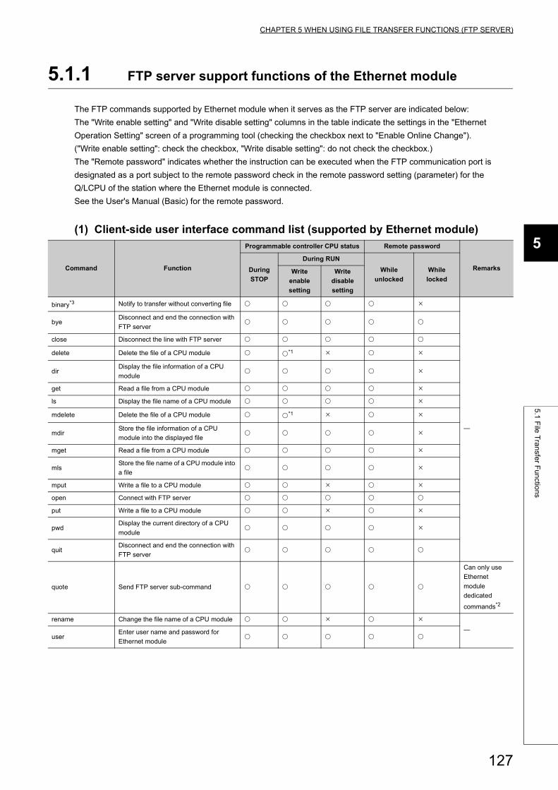
CHAPTER 5 WHEN USING FILE TRANSFER FUNCTIONS (FTP SERVER)
5
5.1
File
Tra
nsfe
r Fu
nctio
ns
5.1.1 FTP server support functions of the Ethernet module
The FTP commands supported by Ethernet module when it serves as the FTP server are indicated below:
The "Write enable setting" and "Write disable setting" columns in the table indicate the settings in the "Ethernet
Operation Setting" screen of a programming tool (checking the checkbox next to "Enable Online Change").
("Write enable setting": check the checkbox, "Write disable setting": do not check the checkbox.)
The "Remote password" indicates whether the instruction can be executed when the FTP communication port is
designated as a port subject to the remote password check in the remote password setting (parameter) for the
Q/LCPU of the station where the Ethernet module is connected.
See the User's Manual (Basic) for the remote password.
(1) Client-side user interface command list (supported by Ethernet module)
Command Function
Programmable controller CPU status Remote password
RemarksDuring
STOP
During RUN
While
unlocked
While
lockedWrite
enable
setting
Write
disable
setting
binary*3 Notify to transfer without converting file
byeDisconnect and end the connection with
FTP server
close Disconnect the line with FTP server
delete Delete the file of a CPU module *1
dirDisplay the file information of a CPU
module
get Read a file from a CPU module
ls Display the file name of a CPU module
mdelete Delete the file of a CPU module *1
mdirStore the file information of a CPU
module into the displayed file
mget Read a file from a CPU module
mlsStore the file name of a CPU module into
a file
mput Write a file to a CPU module
open Connect with FTP server
put Write a file to a CPU module
pwdDisplay the current directory of a CPU
module
quitDisconnect and end the connection with
FTP server
quote Send FTP server sub-command
Can only use
Ethernet
module
dedicated
commands*2
rename Change the file name of a CPU module
user
Enter user name and password for
Ethernet module
127
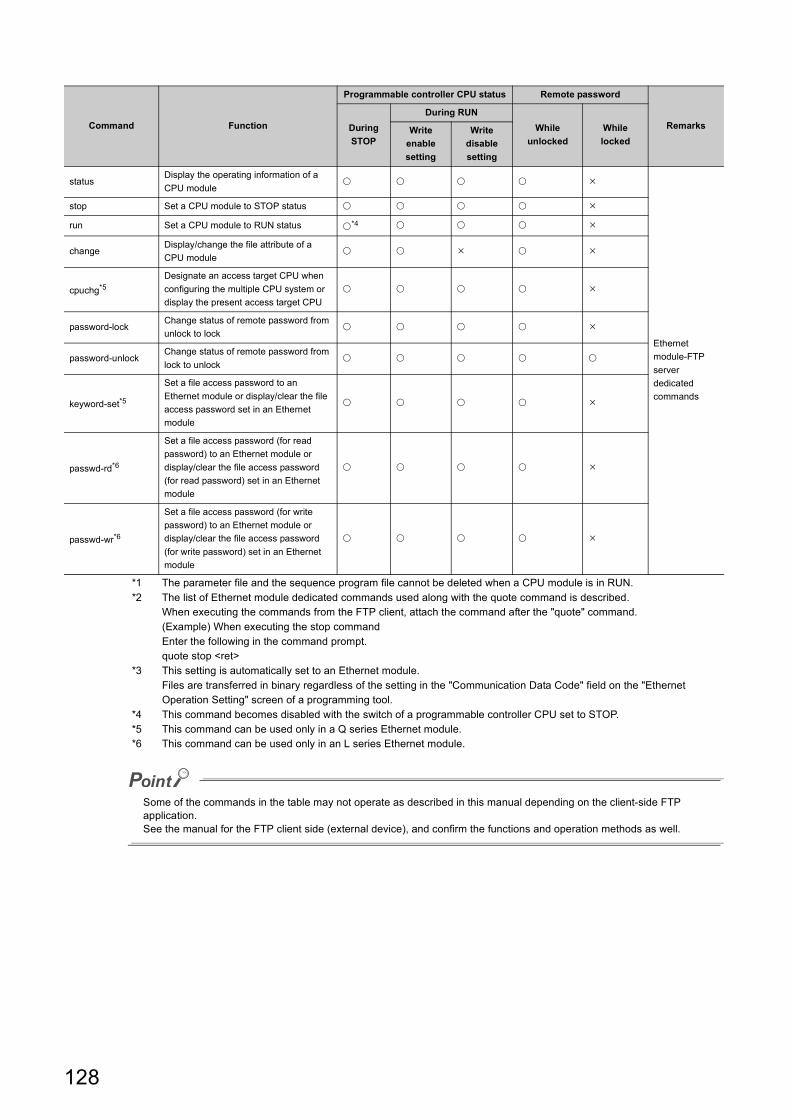
*1 The parameter file and the sequence program file cannot be deleted when a CPU module is in RUN.*2 The list of Ethernet module dedicated commands used along with the quote command is described.
When executing the commands from the FTP client, attach the command after the "quote" command.(Example) When executing the stop commandEnter the following in the command prompt.quote stop <ret>
*3 This setting is automatically set to an Ethernet module.Files are transferred in binary regardless of the setting in the "Communication Data Code" field on the "Ethernet Operation Setting" screen of a programming tool.
*4 This command becomes disabled with the switch of a programmable controller CPU set to STOP.*5 This command can be used only in a Q series Ethernet module.*6 This command can be used only in an L series Ethernet module.
Some of the commands in the table may not operate as described in this manual depending on the client-side FTP application.See the manual for the FTP client side (external device), and confirm the functions and operation methods as well.
statusDisplay the operating information of a
CPU module
Ethernet
module-FTP
server
dedicated
commands
stop Set a CPU module to STOP status
run Set a CPU module to RUN status *4
changeDisplay/change the file attribute of a
CPU module
cpuchg*5
Designate an access target CPU when
configuring the multiple CPU system or
display the present access target CPU
password-lockChange status of remote password from
unlock to lock
password-unlockChange status of remote password from
lock to unlock
keyword-set*5
Set a file access password to an
Ethernet module or display/clear the file
access password set in an Ethernet
module
passwd-rd*6
Set a file access password (for read
password) to an Ethernet module or
display/clear the file access password
(for read password) set in an Ethernet
module
passwd-wr*6
Set a file access password (for write
password) to an Ethernet module or
display/clear the file access password
(for write password) set in an Ethernet
module
Command Function
Programmable controller CPU status Remote password
RemarksDuring
STOP
During RUN
While
unlocked
While
lockedWrite
enable
setting
Write
disable
setting
128
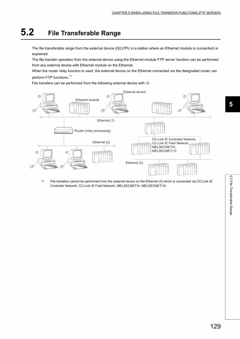
CHAPTER 5 WHEN USING FILE TRANSFER FUNCTIONS (FTP SERVER)
5
5.2
File
Tra
nsfe
rab
le R
an
ge
5.2 File Transferable Range
The file transferable range from the external device (Q/LCPU in a station where an Ethernet module is connected) is
explained.
The file transfer operation from the external device using the Ethernet module FTP server function can be performed
from any external device with Ethernet module on the Ethernet.
When the router relay function is used, the external device on the Ethernet connected via the designated router can
perform FTP functions.*1
File transfers can be performed from the following external device with .
*1 File transfers cannot be performed from the external device on the Ethernet (3) which is connected via CC-Link IE Controller Network, CC-Link IE Field Network, MELSECNET/H, MELSECNET/10.
Ethernet (3)
Ethernet (2)
Ethernet (1)
��
���
Ethernet module
CC-Link IE Controller Network, CC-Link IE Field Network, MELSECNET/H, MELSECNET/10
External device
Router (relay processing)
129
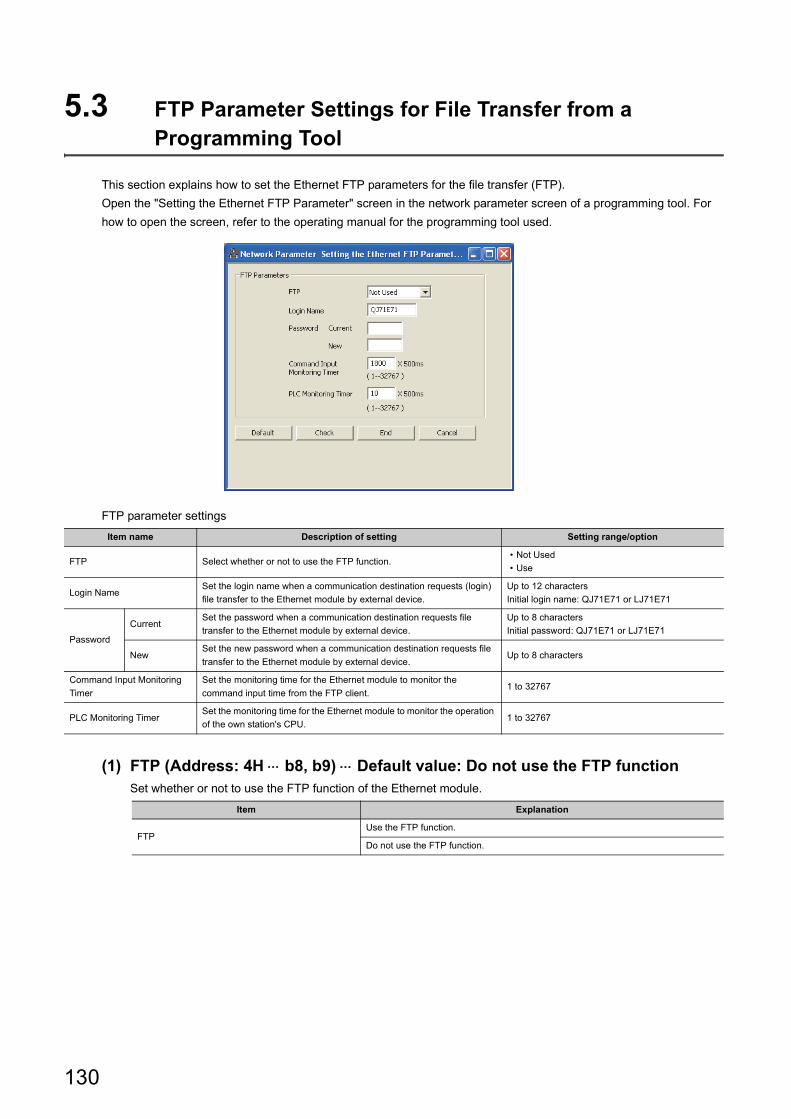
5.3 FTP Parameter Settings for File Transfer from a Programming Tool
This section explains how to set the Ethernet FTP parameters for the file transfer (FTP).
Open the "Setting the Ethernet FTP Parameter" screen in the network parameter screen of a programming tool. For
how to open the screen, refer to the operating manual for the programming tool used.
FTP parameter settings
(1) FTP (Address: 4H b8, b9) Default value: Do not use the FTP functionSet whether or not to use the FTP function of the Ethernet module.
Item name Description of setting Setting range/option
FTP Select whether or not to use the FTP function.• Not Used
• Use
Login NameSet the login name when a communication destination requests (login)
file transfer to the Ethernet module by external device.
Up to 12 characters
Initial login name: QJ71E71 or LJ71E71
Password
CurrentSet the password when a communication destination requests file
transfer to the Ethernet module by external device.
Up to 8 characters
Initial password: QJ71E71 or LJ71E71
NewSet the new password when a communication destination requests file
transfer to the Ethernet module by external device.Up to 8 characters
Command Input Monitoring
Timer
Set the monitoring time for the Ethernet module to monitor the
command input time from the FTP client.1 to 32767
PLC Monitoring TimerSet the monitoring time for the Ethernet module to monitor the operation
of the own station's CPU.1 to 32767
Item Explanation
FTPUse the FTP function.
Do not use the FTP function.
130
CHAPTER 5 WHEN USING FILE TRANSFER FUNCTIONS (FTP SERVER)
5
5.3
FT
P P
ara
me
ter S
ettin
gs fo
r File
Tra
nsfe
r from
a P
rog
ram
min
g T
oo
l
(2) Log-in name and password (Address: 3B0H), (3B6H) Default value: QJ71E71
(QCPU) and LJ71E71 (LCPU)
(a) Set the login name and password for the external device to request (login) file
transfer to the Ethernet module in order to use the FTP server function of the
Ethernet module.
(b) If the FTP login name is changed and invalid characters are entered, QJ71E71 or
LJ71E71 is set as the login name.
(c) If the password is changed and invalid characters are entered, QJ71E71 or LJ71E71
is set as the password.
(3) Command input monitoring timer (address: 3BAH) Default value: 1800
(0708H) (15min)
(a) Set the monitoring time for the Ethernet module to monitor the command input time
from the FTP client when it operates as the FTP server.
(b) It is recommended to use the default value for this timer value as much as possible.
When changing the setting value, determine the command input monitoring timer value upon consulting the
administrator of the external device or system.
(c) Designate the setting value in the range of <1H to 7FFFH/1 to 32767>.
(15 min at the default value of 1800)
The FTP connection is disconnected if there is no command input from the FTP client side within the time
designated by the command input monitoring timer value after the FTP client login.
When restarting the file transfer, start over from the login operation again.
(4) PLC monitoring timer (address: 3BBH); Default value: 10 (000AH) (5s)
(a) Set the monitoring time for the Ethernet module to monitor the operation of the own
station's Q/LCPU when the Ethernet module is operating as the FTP server.
(b) A timeout may occur due to long internal processing time when file operation is
performed in a CPU module with a large program capacity. If a timeout occurs,
extend the CPU monitoring timer value.
(c) Designate the setting value in the range of <1H to 7FFFH/1 to 32767>.
The FTP connection is disconnected if a Q/LCPU monitoring error is detected after the FTP client login.
When restarting the file transfer, make sure that the own station's Q/LCPU is operating normally and start over
from the login operation again.
131
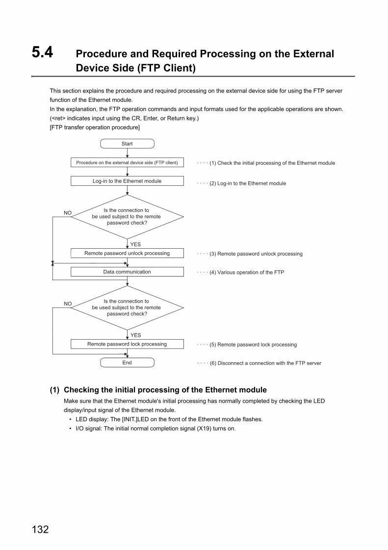
5.4 Procedure and Required Processing on the External Device Side (FTP Client)
This section explains the procedure and required processing on the external device side for using the FTP server
function of the Ethernet module.
In the explanation, the FTP operation commands and input formats used for the applicable operations are shown.
(<ret> indicates input using the CR, Enter, or Return key.)
[FTP transfer operation procedure]
(1) Checking the initial processing of the Ethernet moduleMake sure that the Ethernet module's initial processing has normally completed by checking the LED
display/input signal of the Ethernet module.
• LED display: The [INIT.]LED on the front of the Ethernet module flashes.
• I/O signal: The initial normal completion signal (X19) turns on.
YES
NO
YES
NO
Start
Procedure on the external device side (FTP client)
Log-in to the Ethernet module
Is the connection to be used subject to the remote
password check?
Remote password unlock processing
Data communication
Is the connection to be used subject to the remote
password check?
Remote password lock processing
End
· · · · (1) Check the initial processing of the Ethernet module
· · · · (2) Log-in to the Ethernet module
· · · · (3) Remote password unlock processing
· · · · (4) Various operation of the FTP
· · · · (5) Remote password lock processing
· · · · (6) Disconnect a connection with the FTP server
132
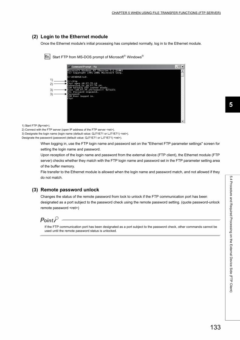
CHAPTER 5 WHEN USING FILE TRANSFER FUNCTIONS (FTP SERVER)
5
5.4
Pro
ced
ure
an
d R
eq
uire
d P
roce
ssing
on
the
Exte
rna
l De
vice S
ide
(FT
P C
lien
t)
(2) Login to the Ethernet moduleOnce the Ethernet module's initial processing has completed normally, log in to the Ethernet module.
Start FTP from MS-DOS prompt of Microsoft Windows
When logging in, use the FTP login name and password set on the "Ethernet FTP parameter settings" screen for
setting the login name and password.
Upon reception of the login name and password from the external device (FTP client), the Ethernet module (FTP
server) checks whether they match with the FTP login name and password set in the FTP parameter setting area
of the buffer memory.
File transfer to the Ethernet module is allowed when the login name and password match, and not allowed if they
do not match.
(3) Remote password unlockChanges the status of the remote password from lock to unlock if the FTP communication port has been
designated as a port subject to the password check using the remote password setting. (quote password-unlock
remote password <ret>)
If the FTP communication port has been designated as a port subject to the password check, other commands cannot be used until the remote password status is unlocked.
1) Start FTP (ftp<ret>).
2) Connect with the FTP server (open IP address of the FTP server <ret>).
3) Designate the login name (login name (default value: QJ71E71 or LJ71E71) <ret>).
Designate the password (password (default value: QJ71E71 or LJ71E71) <ret>).
1)2)
3)3)
133
(4) Various operation of the FTP
1. Designate an access target CPU if the QCPU is configured as a multiple CPU system.
The control CPU of the Ethernet module will be the access target CPU after login.
(quote cpuchg access target CPU <ret>)
2. Notifies file transfer to a target file without converting the file.
(binary <ret>)
3. If a password is registered in the Q/LCPU file for file transfer, set the password in the Ethernet
module.
QCPU: (quote keyword-set password <ret>)
LCPU: (quote passwd-rd password <ret>) or (quote passwd-wr password <ret>)
4. Performs the file transfer operation using the FTP commands described in Page 141, Section 5.6.
Writing to a parameter file used in the current operation of the Q/LCPU and to a file of the running sequence program that is stored in the Q/LCPU program memory is performed after placing the Q/LCPU in the STOP status.
(5) Remote password lockChanges the status of the remote password from unlock to lock if the FTP communication port has been
designated as a port subject to the remote password check using the remote password setting. (quote password-
lock <ret>)
134
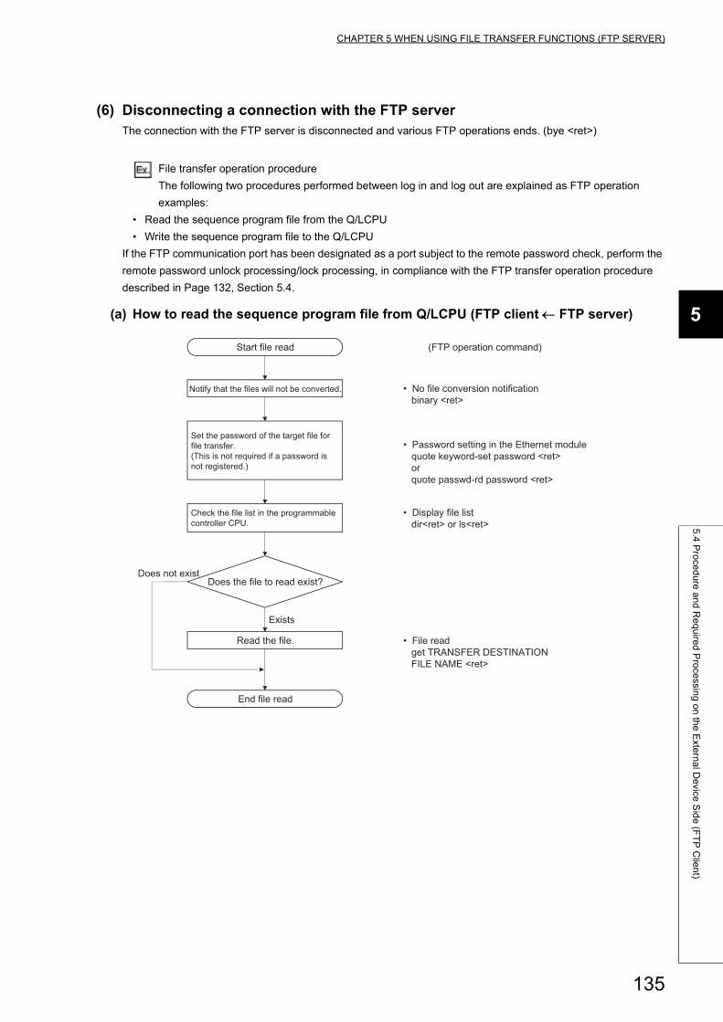
CHAPTER 5 WHEN USING FILE TRANSFER FUNCTIONS (FTP SERVER)
5
5.4
Pro
ced
ure
an
d R
eq
uire
d P
roce
ssing
on
the
Exte
rna
l De
vice S
ide
(FT
P C
lien
t)
(6) Disconnecting a connection with the FTP serverThe connection with the FTP server is disconnected and various FTP operations ends. (bye <ret>)
File transfer operation procedure
The following two procedures performed between log in and log out are explained as FTP operation
examples:
• Read the sequence program file from the Q/LCPU
• Write the sequence program file to the Q/LCPU
If the FTP communication port has been designated as a port subject to the remote password check, perform the
remote password unlock processing/lock processing, in compliance with the FTP transfer operation procedure
described in Page 132, Section 5.4.
(a) How to read the sequence program file from Q/LCPU (FTP client FTP server)
Read the file.
Exists
Start file read
Notify that the files will not be converted.
Set the password of the target file for file transfer. (This is not required if a password is not registered.)
Check the file list in the programmable controller CPU.
Does not existDoes the file to read exist?
End file read
(FTP operation command)
• No file conversion notification binary <ret>
• Password setting in the Ethernet module quote keyword-set password <ret> or quote passwd-rd password <ret>
• Display file list dir<ret> or ls<ret>
• File read get TRANSFER DESTINATION FILE NAME <ret>
135
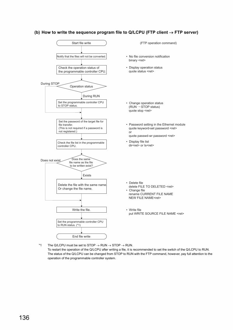
(b) How to write the sequence program file to Q/LCPU (FTP client FTP server)
*1 The Q/LCPU must be set to STOP RUN STOP RUN.To restart the operation of the Q/LCPU after writing a file, it is recommended to set the switch of the Q/LCPU to RUN. The status of the Q/LCPU can be changed from STOP to RUN with the FTP command, however, pay full attention to the operation of the programmable controller system.
Exists
Operation status
Start file write
Notify that the files will not be converted.
Check the operation status of the programmable controller CPU.
During STOP
During RUN
Set the programmable controller CPU to STOP status.
Set the password of the target file for file transfer. (This is not required if a password is not registered.)
Check the file list in the programmable controller CPU.
Does not exist Does the same file name as the file to be written exist?
Delete the file with the same name. Or change the file name.
Write the file.
Set the programmable controller CPU to RUN status. (*1)
End file write
(FTP operation command)
• No file conversion notification binary <ret>
• Display operation status quote status <ret>
• Change operation status (RUN STOP status) quote stop <ret>
• Password setting in the Ethernet module quote keyword-set password <ret> or quote passwd-wr password <ret>
• Display file list dir<ret> or Is<ret>
• Delete file delete FILE TO DELETED <ret>• Change file rename CURRENT FILE NAME NEW FILE NAME<ret>
• Write file put WRITE SOURCE FILE NAME <ret>
136
CHAPTER 5 WHEN USING FILE TRANSFER FUNCTIONS (FTP SERVER)
5
5.5
Pre
cau
tion
s wh
en
Usin
g th
e F
ile T
ran
sfer F
un
ction
s
5.5 Precautions when Using the File Transfer Functions
The precautions when using the Ethernet module FTP server functions are explained.
(1) Precautions when designing a system which uses file transfer functions
(a) For the system
When performing file transfers with the system in operation or controlling the status of the programmable
controller, design the system (such as configuring an interlocking circuit in the sequence program) so that the
safety of the overall system is always maintained.
(b) For external devices
Some of the FTP operation commands on the FTP client (external devices) supported by the Ethernet module
as a FTP server may not operate as described in this manual, depending on the client side FTP application.
See the manual on the FTP client (external devices), and confirm the functions and operation methods.
(c) For the Q/LCPU
• Only files that can be created/generated by the user with a programming tool can be transferred. (
Page 143, Section 5.6.2)
• Files can be transferred only to the own station Q/LCPU with the Ethernet module connected. Designate
an access target CPU if the own station's QCPU is configured in a multiple CPU system.
• When file read/write is performed by the file transfer functions while Q/LCPU is running, the Q/LCPU's
sequence scan time may take longer than when using Ethernet module's other functions, and the file
read/write take a few minutes or longer depending on the file size or sequence scan. The file read/write
processing time may take even longer depending on various conditions such as the Ethernet line load (line
traffic), number of connections used at the same time (exchange processing which uses another
connection), and the system configuration.
(2) Precautions when starting up the Ethernet moduleWhen the QCPU is write-protected (DIP switch 1 is on), file transfers which perform write (attribute change, file
write, etc.) cannot be performed. (Excluding the Universal model QCPU.)
137
(3) Precautions common to any usage of the file transfer functions
(a) For an external device
When a timeout error occurs during file transfer using the FTP function, the FTP function line is closed
(disconnection) regardless of the settings of the programming tool.
When restarting the file transfer, login to the Ethernet module from the FTP client again.
(b) For the Q/LCPU
• If a password is registered in the target file for file transfer, transfer that password (set in the Ethernet
module) using the FTP operation command after login. If a password is registered, that file cannot be
accessed unless a password of the same character string is designated. The password is a character
string for file access that the user registers in the Q/LCPU and it allows/prohibits access to the target file.
• The Q/LCPU files of target file transfer must be only the files in the root directory for each memory.
• When the Q/LCPU file being accessed, do not perform any Q/LCPU key switch operations, change
operation status with the programming tool (such as RUN STOP and STOP RUN), turn off power,
reset power, or install/remove the memory card or SD memory card. If any of these operations are
performed, the Q/LCPU files will corrupt and the Q/LCPU may not be able to start again.
• Do not perform any file operations (read/write/change file information) from the programming tool when
the FTP function is in operation. When file operations are performed from a peripheral device, etc. while
the FTP function is in operation, the FTP function may abnormally end.
• If the FTP communication port is designated as a port subject to the remote password check, perform the
file transfer operation after changing the remote password status from lock to unlock. Perform the lock
processing for the remote password when the file transfer processing is completed. If the FTP
communication port is not designated as a port subject to the remote password check, the operation is
completed normally when the remote password unlock processing is performed. The remote password is
a character string registered in the Q/LCPU with a programming tool by a user and data to allow/prohibit
access to the Q/LCPU of another station via the Q/LCPU in the station with the Ethernet module
connected or via the station with the Ethernet module connected.
(4) Precaution when logging in to the Ethernet module (FTP server)Only one external device (FTP client) can log in to the Ethernet module at a time.
138
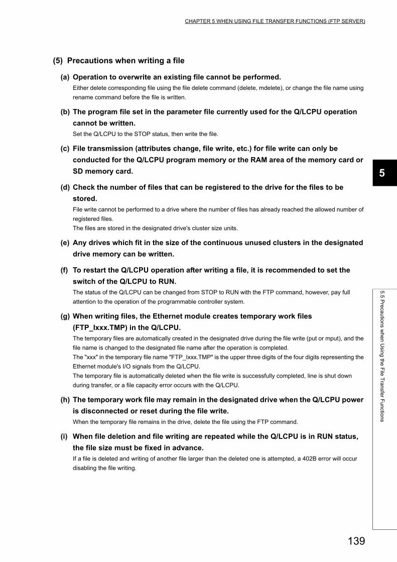
CHAPTER 5 WHEN USING FILE TRANSFER FUNCTIONS (FTP SERVER)
5
5.5
Pre
cau
tion
s wh
en
Usin
g th
e F
ile T
ran
sfer F
un
ction
s
(5) Precautions when writing a file
(a) Operation to overwrite an existing file cannot be performed.
Either delete corresponding file using the file delete command (delete, mdelete), or change the file name using
rename command before the file is written.
(b) The program file set in the parameter file currently used for the Q/LCPU operation
cannot be written.
Set the Q/LCPU to the STOP status, then write the file.
(c) File transmission (attributes change, file write, etc.) for file write can only be
conducted for the Q/LCPU program memory or the RAM area of the memory card or
SD memory card.
(d) Check the number of files that can be registered to the drive for the files to be
stored.
File write cannot be performed to a drive where the number of files has already reached the allowed number of
registered files.
The files are stored in the designated drive's cluster size units.
(e) Any drives which fit in the size of the continuous unused clusters in the designated
drive memory can be written.
(f) To restart the Q/LCPU operation after writing a file, it is recommended to set the
switch of the Q/LCPU to RUN.
The status of the Q/LCPU can be changed from STOP to RUN with the FTP command, however, pay full
attention to the operation of the programmable controller system.
(g) When writing files, the Ethernet module creates temporary work files
(FTP_Ixxx.TMP) in the Q/LCPU.
The temporary files are automatically created in the designated drive during the file write (put or mput), and the
file name is changed to the designated file name after the operation is completed.
The "xxx" in the temporary file name "FTP_Ixxx.TMP" is the upper three digits of the four digits representing the
Ethernet module's I/O signals from the Q/LCPU.
The temporary file is automatically deleted when the file write is successfully completed, line is shut down
during transfer, or a file capacity error occurs with the Q/LCPU.
(h) The temporary work file may remain in the designated drive when the Q/LCPU power
is disconnected or reset during the file write.
When the temporary file remains in the drive, delete the file using the FTP command.
(i) When file deletion and file writing are repeated while the Q/LCPU is in RUN status,
the file size must be fixed in advance.
If a file is deleted and writing of another file larger than the deleted one is attempted, a 402B error will occur
disabling the file writing.
139
(6) Precautions when deleting files
(a) When determining the timing to delete files, consider the system operation as a
whole including the functions of Q/LCPU and a programming tool.
(b) The parameter file and program file cannot be deleted during the Q/LCPU is
performing "RUN".
Delete these files after setting the Q/LCPU to the STOP status.
(c) Files with read-only attribute and files that are locked from another device or
function cannot be deleted.
The file attributes can be changed using the FTP operation command, "quote change".
(d) Files can be deleted only from the Q/LCPU program memory or the RAM area of the
memory card or SD memory card.
(e) After deleting a file with the Q/LCPU in RUN status, do not read or write the data of
the deleted file by the sequence program.
Doing so may result in an operation error detected in the Q/LCPU.
(7) Precautions for FTP passwordWhen forgetting the FTP password, reset FTP parameters in the following procedure.
1. Read the parameters from Q/LCPU to the programming tool.
2. Click the "Default" button in the "Setting the Ethernet FTP parameters." screen and then return all
the parameters to the default values.
3. Set the FTP parameters again.
4. Write the set parameters to the Q/LCPU in the "Write to PLC" screen.
To open the "Write to PLC" screen, select [Online] [Write to PLC].
5. Enable the parameters by powering off and on or resetting the CPU module.
140
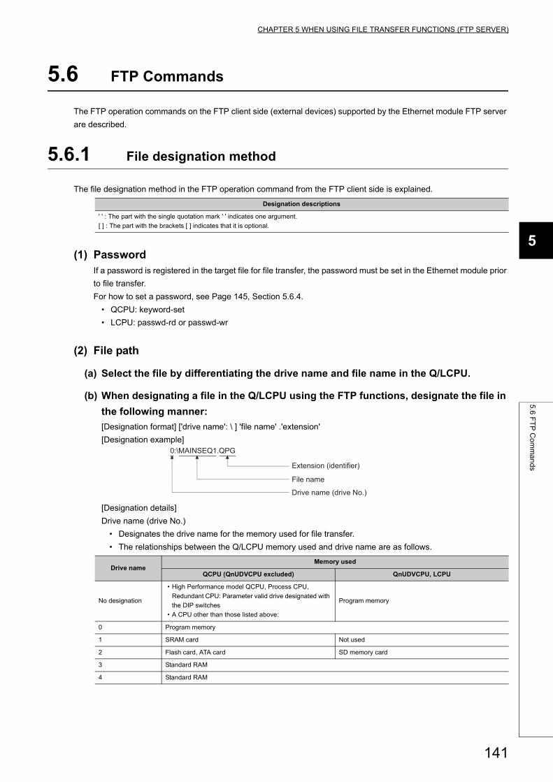
CHAPTER 5 WHEN USING FILE TRANSFER FUNCTIONS (FTP SERVER)
5
5.6
FT
P C
om
ma
nd
s
5.6 FTP Commands
The FTP operation commands on the FTP client side (external devices) supported by the Ethernet module FTP server
are described.
5.6.1 File designation method
The file designation method in the FTP operation command from the FTP client side is explained.
(1) PasswordIf a password is registered in the target file for file transfer, the password must be set in the Ethernet module prior
to file transfer.
For how to set a password, see Page 145, Section 5.6.4.
• QCPU: keyword-set
• LCPU: passwd-rd or passwd-wr
(2) File path
(a) Select the file by differentiating the drive name and file name in the Q/LCPU.
(b) When designating a file in the Q/LCPU using the FTP functions, designate the file in
the following manner:
[Designation format] ['drive name': \ ] 'file name' .'extension'
[Designation example]
[Designation details]
Drive name (drive No.)
• Designates the drive name for the memory used for file transfer.
• The relationships between the Q/LCPU memory used and drive name are as follows.
Designation descriptions
' ' : The part with the single quotation mark ' ' indicates one argument.
[ ] : The part with the brackets [ ] indicates that it is optional.
Drive nameMemory used
QCPU (QnUDVCPU excluded) QnUDVCPU, LCPU
No designation
• High Performance model QCPU, Process CPU,
Redundant CPU: Parameter valid drive designated with
the DIP switches
• A CPU other than those listed above:
Program memory
0 Program memory
1 SRAM card Not used
2 Flash card, ATA card SD memory card
3 Standard RAM
4 Standard RAM
Drive name (drive No.)
0:\MAINSEQ1.QPG
File name
Extension (identifier)
141
• File name, extension
• The corresponding file for the file transfer is designated.
• The file name must be designated according to the file name rules of the programming tool. Alphabets
(uppercase), numbers, and symbols can be used. Alphabets (lowercase) cannot be used.
• For the extension (identifier), the name fixed by the Q/LCPU must be used. The corresponding file
extension is designated as seen in Page 141, Section 5.6.1.
• For details on the file names and extensions, see the operating manual for the programming tool used.
• When using a FTP operation command which can designate multiple files, the files (file names and
extensions) are designated using wild card symbols, * / ?."
● In the description of the FTP operation commands, the file name indicates both the file name and extension.
● It is recommended to use the following method to treat the file name from the external device.• Use the ASCII code characters (upper case for the alphabet letters) for the file to be written to the FTP server.• Do not change the file name for the file read from the Q/LCPU.
● Each memory for Q/LCPU does not have any sub-directories.Each file is stored in the root directory.
(3) AttributesSpecify the following when changing the attributes of the file stored in the Q/LCPU drive to be transferred:
"r" (Read Only) "w" (read/write enabled)
See the "quote change" command in Page 145, Section 5.6.4.
File name: Max. 8 characters
Extension: Max. 3 characters
*: Files containing the characters before "*" and any set of characters (including none) replacing the "*"
are designated.
Example 1 When designating all files with the "QPG" extension
*.QPG
Example 2When designating file names which start with "MAIN" and the extension is "QPG"
MAIN*.QPG
?: The files containing the text string designated (including none), replacing ? with any character including
none. ("?" can be used multiple times.)
Example 1The letter after "MAIN" is any character and the extension is "QPG"
MAIN?SEQ.QPG
Example 2 To designate all files whose extension start with "QP"
*.QP?
Example 3 To designate all files whose extension start with "Q"
*.Q??
142
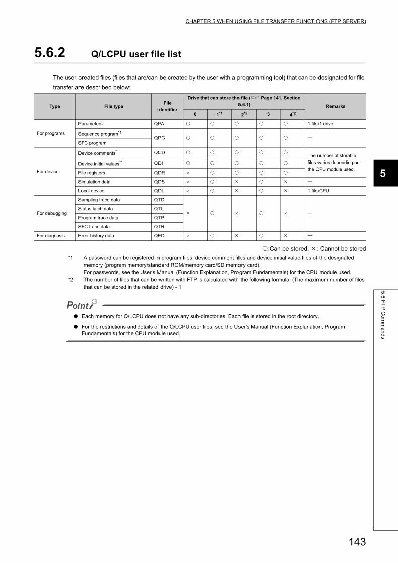
CHAPTER 5 WHEN USING FILE TRANSFER FUNCTIONS (FTP SERVER)
5
5.6
FT
P C
om
ma
nd
s
5.6.2 Q/LCPU user file list
The user-created files (files that are/can be created by the user with a programming tool) that can be designated for file
transfer are described below:
:Can be stored, : Cannot be stored
*1 A password can be registered in program files, device comment files and device initial value files of the designated memory (program memory/standard ROM/memory card/SD memory card).For passwords, see the User's Manual (Function Explanation, Program Fundamentals) for the CPU module used.
*2 The number of files that can be written with FTP is calculated with the following formula: (The maximum number of files that can be stored in the related drive) - 1
● Each memory for Q/LCPU does not have any sub-directories. Each file is stored in the root directory.
● For the restrictions and details of the Q/LCPU user files, see the User's Manual (Function Explanation, Program Fundamentals) for the CPU module used.
Type File typeFile
identifier
Drive that can store the file ( Page 141, Section
5.6.1) Remarks
0 1*1 2*2 3 4*2
For programs
Parameters QPA 1 file/1 drive
Sequence program*1
QPG SFC program
For device
Device comments*1 QCD The number of storable
files varies depending on
the CPU module used.Device initial values*1 QDI
File registers QDR
Simulation data QDS
Local device QDL 1 file/CPU
For debugging
Sampling trace data QTD
Status latch data QTL
Program trace data QTP
SFC trace data QTR
For diagnosis Error history data QFD
143
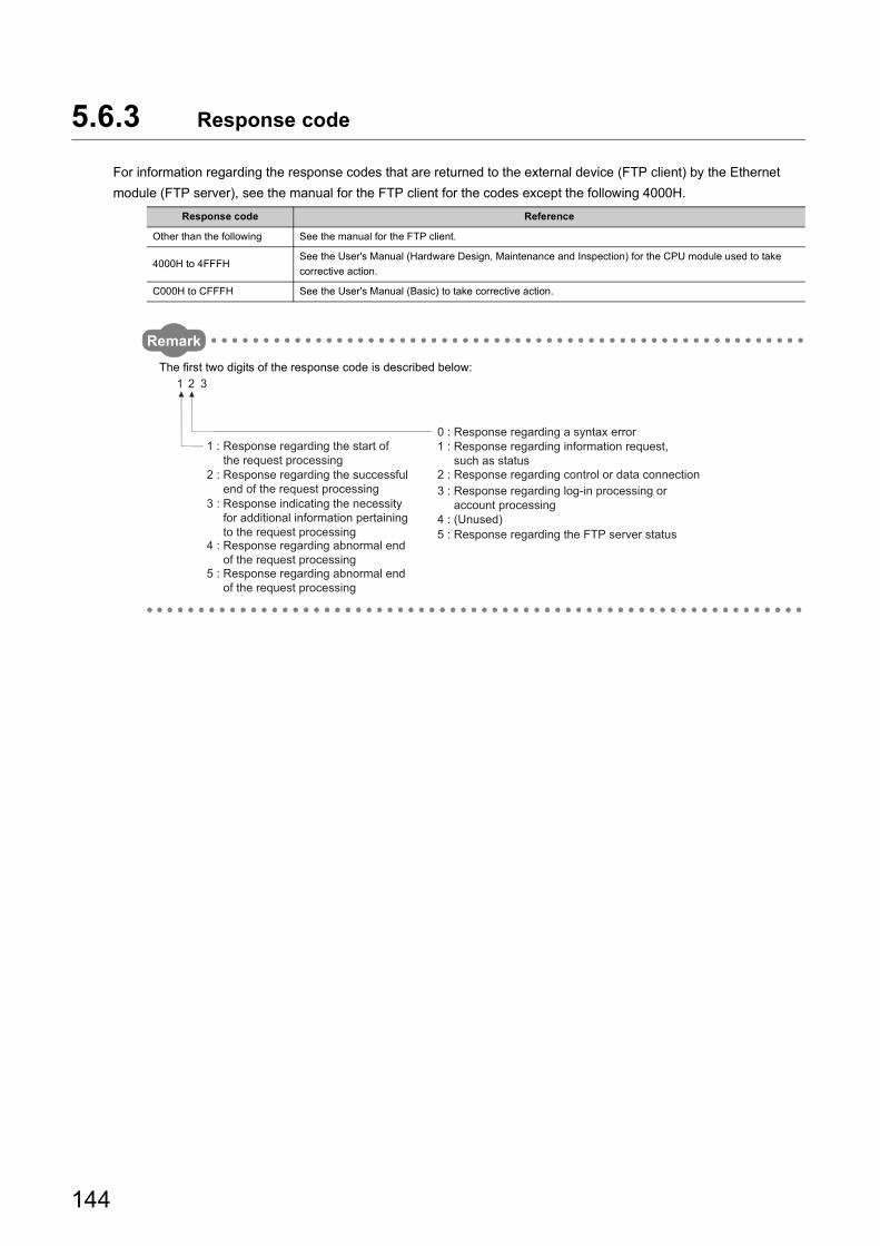
5.6.3 Response code
For information regarding the response codes that are returned to the external device (FTP client) by the Ethernet
module (FTP server), see the manual for the FTP client for the codes except the following 4000H.
Remark
The first two digits of the response code is described below:
Response code Reference
Other than the following See the manual for the FTP client.
4000H to 4FFFHSee the User's Manual (Hardware Design, Maintenance and Inspection) for the CPU module used to take
corrective action.
C000H to CFFFH See the User's Manual (Basic) to take corrective action.
1 2 3
5 : Response regarding the FTP server status4 : (Unused)
3 : Response regarding log-in processing or account processing
2 : Response regarding control or data connection
1 : Response regarding information request, such as status
0 : Response regarding a syntax error
5 : Response regarding abnormal end of the request processing
4 : Response regarding abnormal end of the request processing
3 : Response indicating the necessity for additional information pertaining to the request processing
2 : Response regarding the successful end of the request processing
1 : Response regarding the start of the request processing
144
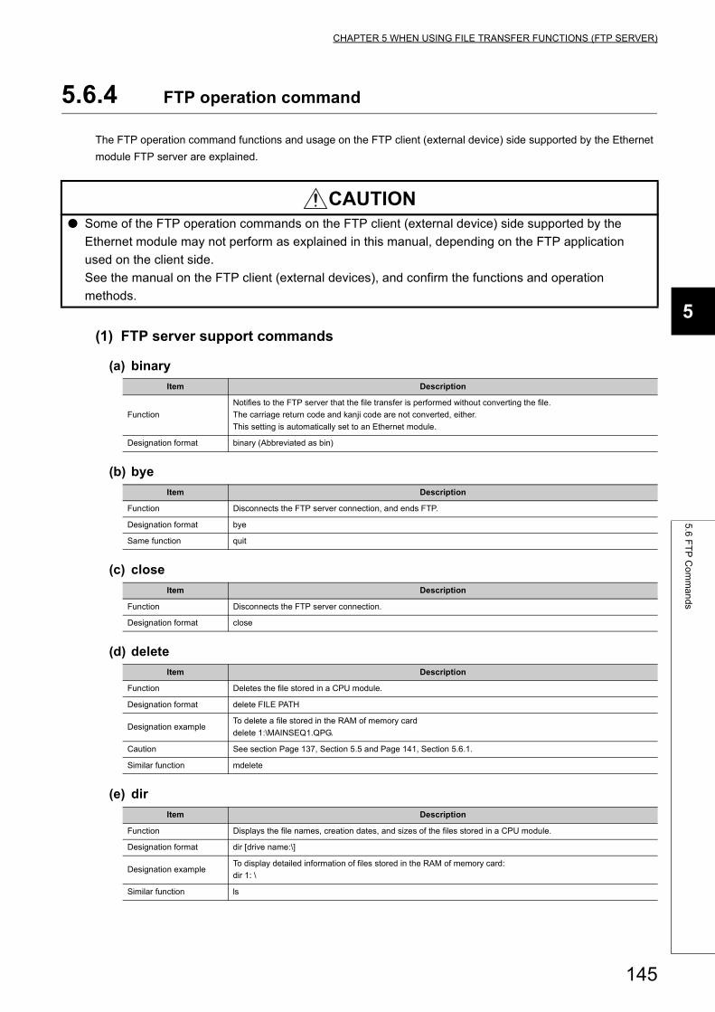
CHAPTER 5 WHEN USING FILE TRANSFER FUNCTIONS (FTP SERVER)
5
5.6
FT
P C
om
ma
nd
s
5.6.4 FTP operation command
The FTP operation command functions and usage on the FTP client (external device) side supported by the Ethernet
module FTP server are explained.
(1) FTP server support commands
(a) binary
(b) bye
(c) close
(d) delete
(e) dir
CAUTION● Some of the FTP operation commands on the FTP client (external device) side supported by the
Ethernet module may not perform as explained in this manual, depending on the FTP application
used on the client side.
See the manual on the FTP client (external devices), and confirm the functions and operation
methods.
Item Description
Function
Notifies to the FTP server that the file transfer is performed without converting the file.
The carriage return code and kanji code are not converted, either.
This setting is automatically set to an Ethernet module.
Designation format binary (Abbreviated as bin)
Item Description
Function Disconnects the FTP server connection, and ends FTP.
Designation format bye
Same function quit
Item Description
Function Disconnects the FTP server connection.
Designation format close
Item Description
Function Deletes the file stored in a CPU module.
Designation format delete FILE PATH
Designation exampleTo delete a file stored in the RAM of memory card
delete 1:\MAINSEQ1.QPG.
Caution See section Page 137, Section 5.5 and Page 141, Section 5.6.1.
Similar function mdelete
Item Description
Function Displays the file names, creation dates, and sizes of the files stored in a CPU module.
Designation format dir [drive name:\]
Designation exampleTo display detailed information of files stored in the RAM of memory card:
dir 1: \
Similar function ls
145
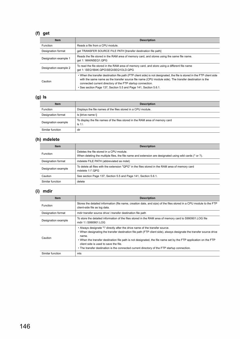
(f) get
(g) ls
(h) mdelete
(i) mdir
Item Description
Function Reads a file from a CPU module.
Designation format get TRANSFER SOURCE FILE PATH [transfer destination file path]
Designation example 1Reads the file stored in the RAM area of memory card, and stores using the same file name.
get 1: \MAINSEQ1.QPG
Designation example 2To read the file stored in the RAM area of memory card, and store using a different file name
get 1: \SEQ1BAK.QPG\SEQ\SEQ1OLD.QPG
Caution
• When the transfer destination file path (FTP client side) is not designated, the file is stored in the FTP client side
with the same name as the transfer source file name (CPU module side). The transfer destination is the
connected current directory of the FTP startup connection.
• See section Page 137, Section 5.5 and Page 141, Section 5.6.1.
Item Description
Function Displays the file names of the files stored in a CPU module.
Designation format ls [drive name:\]
Designation exampleTo display the file names of the files stored in the RAM area of memory card
ls 1:\
Similar function dir
Item Description
FunctionDeletes the file stored in a CPU module.
When deleting the multiple files, the file name and extension are designated using wild cards (* or ?).
Designation format mdelete FILE PATH (abbreviated as mdel)
Designation exampleTo delete all files with the extension "QPG" in the files stored in the RAM area of memory card
mdelete 1:\*.QPG
Caution See section Page 137, Section 5.5 and Page 141, Section 5.6.1.
Similar function delete
Item Description
FunctionStores the detailed information (file name, creation date, and size) of the files stored in a CPU module to the FTP
client-side file as log data.
Designation format mdir transfer source drive:\ transfer destination file path
Designation exampleTo store the detailed information of the files stored in the RAM area of memory card to S990901.LOG file
mdir 1:\ S990901.LOG
Caution
• Always designate "\" directly after the drive name of the transfer source.
• When designating the transfer destination file path (FTP client side), always designate the transfer source drive
name.
• When the transfer destination file path is not designated, the file name set by the FTP application on the FTP
client side is used to save the file.
• The transfer destination is the connected current directory of the FTP startup connection.
Similar function mls
146
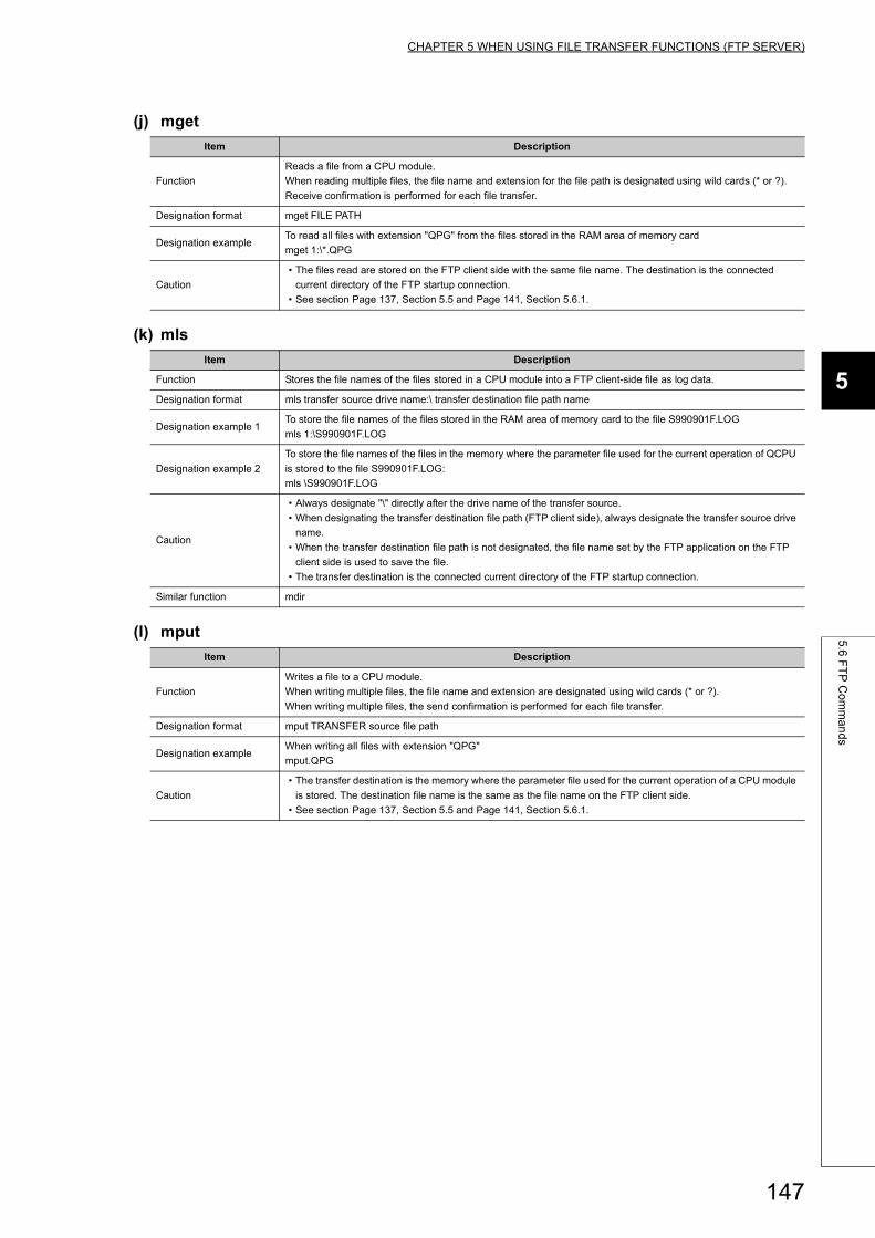
CHAPTER 5 WHEN USING FILE TRANSFER FUNCTIONS (FTP SERVER)
5
5.6
FT
P C
om
ma
nd
s
(j) mget
(k) mls
(l) mput
Item Description
Function
Reads a file from a CPU module.
When reading multiple files, the file name and extension for the file path is designated using wild cards (* or ?).
Receive confirmation is performed for each file transfer.
Designation format mget FILE PATH
Designation exampleTo read all files with extension "QPG" from the files stored in the RAM area of memory card
mget 1:\*.QPG
Caution
• The files read are stored on the FTP client side with the same file name. The destination is the connected
current directory of the FTP startup connection.
• See section Page 137, Section 5.5 and Page 141, Section 5.6.1.
Item Description
Function Stores the file names of the files stored in a CPU module into a FTP client-side file as log data.
Designation format mls transfer source drive name:\ transfer destination file path name
Designation example 1To store the file names of the files stored in the RAM area of memory card to the file S990901F.LOG
mls 1:\S990901F.LOG
Designation example 2
To store the file names of the files in the memory where the parameter file used for the current operation of QCPU
is stored to the file S990901F.LOG:
mls \S990901F.LOG
Caution
• Always designate "\" directly after the drive name of the transfer source.
• When designating the transfer destination file path (FTP client side), always designate the transfer source drive
name.
• When the transfer destination file path is not designated, the file name set by the FTP application on the FTP
client side is used to save the file.
• The transfer destination is the connected current directory of the FTP startup connection.
Similar function mdir
Item Description
Function
Writes a file to a CPU module.
When writing multiple files, the file name and extension are designated using wild cards (* or ?).
When writing multiple files, the send confirmation is performed for each file transfer.
Designation format mput TRANSFER source file path
Designation exampleWhen writing all files with extension "QPG"
mput.QPG
Caution
• The transfer destination is the memory where the parameter file used for the current operation of a CPU module
is stored. The destination file name is the same as the file name on the FTP client side.
• See section Page 137, Section 5.5 and Page 141, Section 5.6.1.
147
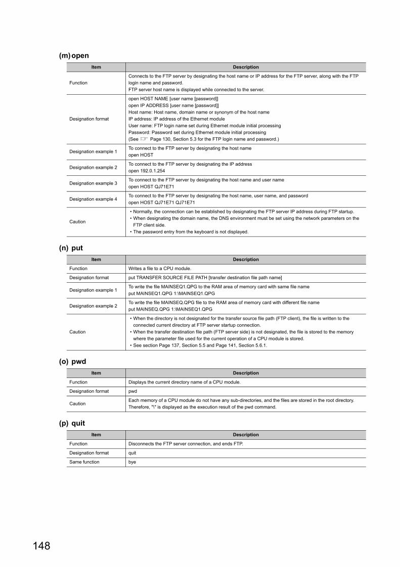
(m)open
(n) put
(o) pwd
(p) quit
Item Description
Function
Connects to the FTP server by designating the host name or IP address for the FTP server, along with the FTP
login name and password.
FTP server host name is displayed while connected to the server.
Designation format
open HOST NAME [user name [password]]
open IP ADDRESS [user name [password]]
Host name: Host name, domain name or synonym of the host name
IP address: IP address of the Ethernet module
User name: FTP login name set during Ethernet module initial processing
Password: Password set during Ethernet module initial processing
(See Page 130, Section 5.3 for the FTP login name and password.)
Designation example 1To connect to the FTP server by designating the host name
open HOST
Designation example 2To connect to the FTP server by designating the IP address
open 192.0.1.254
Designation example 3To connect to the FTP server by designating the host name and user name
open HOST QJ71E71
Designation example 4To connect to the FTP server by designating the host name, user name, and password
open HOST QJ71E71 QJ71E71
Caution
• Normally, the connection can be established by designating the FTP server IP address during FTP startup.
• When designating the domain name, the DNS environment must be set using the network parameters on the
FTP client side.
• The password entry from the keyboard is not displayed.
Item Description
Function Writes a file to a CPU module.
Designation format put TRANSFER SOURCE FILE PATH [transfer destination file path name]
Designation example 1To write the file MAINSEQ1.QPG to the RAM area of memory card with same file name
put MAINSEQ1.QPG 1:\MAINSEQ1.QPG
Designation example 2To write the file MAINSEQ.QPG file to the RAM area of memory card with different file name
put MAINSEQ.QPG 1:\MAINSEQ1.QPG
Caution
• When the directory is not designated for the transfer source file path (FTP client), the file is written to the
connected current directory at FTP server startup connection.
• When the transfer destination file path (FTP server side) is not designated, the file is stored to the memory
where the parameter file used for the current operation of a CPU module is stored.
• See section Page 137, Section 5.5 and Page 141, Section 5.6.1.
Item Description
Function Displays the current directory name of a CPU module.
Designation format pwd
CautionEach memory of a CPU module do not have any sub-directories, and the files are stored in the root directory.
Therefore, "\" is displayed as the execution result of the pwd command.
Item Description
Function Disconnects the FTP server connection, and ends FTP.
Designation format quit
Same function bye
148
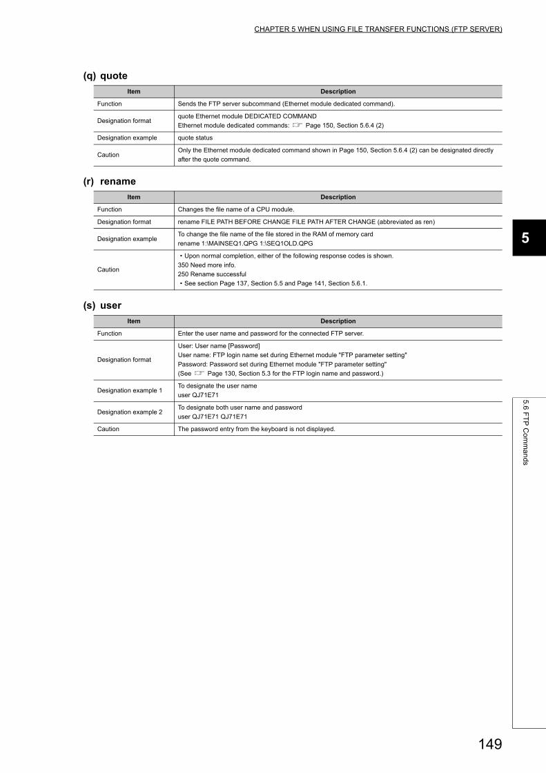
CHAPTER 5 WHEN USING FILE TRANSFER FUNCTIONS (FTP SERVER)
5
5.6
FT
P C
om
ma
nd
s
(q) quote
(r) rename
(s) user
Item Description
Function Sends the FTP server subcommand (Ethernet module dedicated command).
Designation formatquote Ethernet module DEDICATED COMMAND
Ethernet module dedicated commands: Page 150, Section 5.6.4 (2)
Designation example quote status
CautionOnly the Ethernet module dedicated command shown in Page 150, Section 5.6.4 (2) can be designated directly
after the quote command.
Item Description
Function Changes the file name of a CPU module.
Designation format rename FILE PATH BEFORE CHANGE FILE PATH AFTER CHANGE (abbreviated as ren)
Designation exampleTo change the file name of the file stored in the RAM of memory card
rename 1:\MAINSEQ1.QPG 1:\SEQ1OLD.QPG
Caution
• Upon normal completion, either of the following response codes is shown.
350 Need more info.
250 Rename successful
• See section Page 137, Section 5.5 and Page 141, Section 5.6.1.
Item Description
Function Enter the user name and password for the connected FTP server.
Designation format
User: User name [Password]
User name: FTP login name set during Ethernet module "FTP parameter setting"
Password: Password set during Ethernet module "FTP parameter setting"
(See Page 130, Section 5.3 for the FTP login name and password.)
Designation example 1To designate the user name
user QJ71E71
Designation example 2To designate both user name and password
user QJ71E71 QJ71E71
Caution The password entry from the keyboard is not displayed.
149
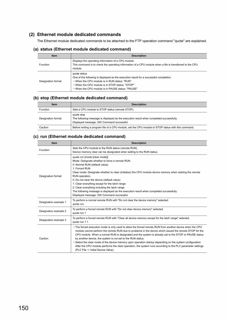
(2) Ethernet module dedicated commandsThe Ethernet module dedicated commands to be attached to the FTP operation command "quote" are explained.
(a) status (Ethernet module dedicated command)
(b) stop (Ethernet module dedicated command)
(c) run (Ethernet module dedicated command)
Item Description
Function
Displays the operating information of a CPU module.
This command is to check the operating information of a CPU module when a file is transferred to the CPU
module.
Designation format
quote status
One of the following is displayed as the execution result for a successful completion.
• When the CPU module is in RUN status: "RUN"
• When the CPU module is in STOP status: "STOP"
• When the CPU module is in PAUSE status: "PAUSE"
Item Description
Function Sets a CPU module to STOP status (remote STOP).
Designation format
quote stop
The following message is displayed as the execution result when completed successfully.
Displayed message: 200 Command successful
Caution Before writing a program file of a CPU module, set the CPU module to STOP status with this command.
Item Description
FunctionSets the CPU module to the RUN status (remote RUN).
Device memory clear can be designated when setting to the RUN status.
Designation format
quote run [mode [clear mode]]
Mode: Designate whether to force a remote RUN.
0: Normal RUN (default value)
1: Forced RUN
Clear mode: Designate whether to clear (initialize) the CPU module device memory when starting the remote
RUN operation.
0: Do not clear the device (default value)
1: Clear everything except for the latch range
2: Clear everything including the latch range
The following message is displayed as the execution result when completed successfully.
Displayed message: 200 Command successful
Designation example 1To perform a normal remote RUN with "Do not clear the device memory" selected.
quote run
Designation example 2To perform a forced remote RUN with "Do not clear device memory" selected.
quote run 1
Designation example 3To perform a forced remote RUN with "Clear all device memory except for the latch range" selected.
quote run 1 1
Caution
• The forced execution mode is only used to allow the forced remote RUN from another device when the CPU
module cannot perform the remote RUN due to problems in the device which issued the remote STOP for the
CPU module. When a normal RUN is designated and the system is already set to the STOP or PAUSE status
by another device, the system is not set to the RUN status.
• Select the clear mode of the device memory upon operation startup depending on the system configuration.
After the CPU module performs the clear operation, the system runs according to the PLC parameter settings
(PLC File Initial Device Value).
150
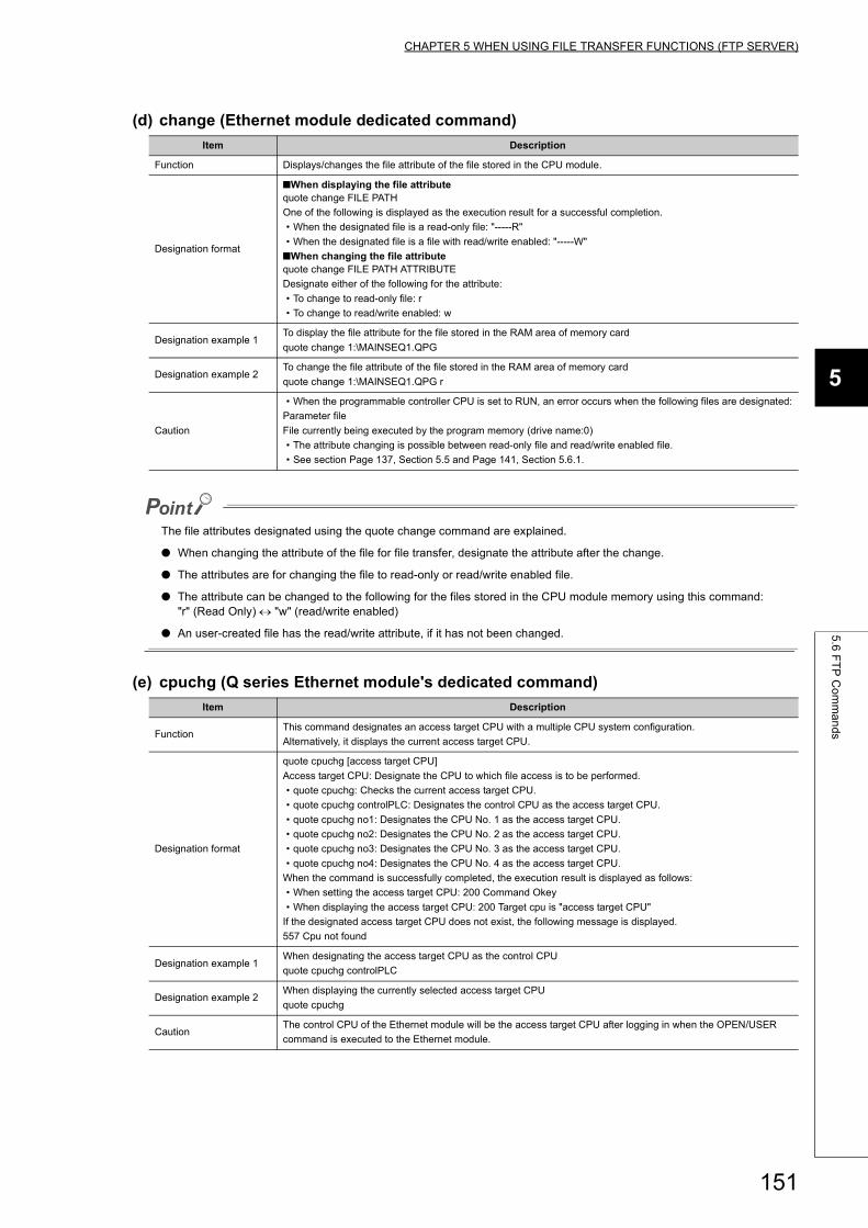
CHAPTER 5 WHEN USING FILE TRANSFER FUNCTIONS (FTP SERVER)
5
5.6
FT
P C
om
ma
nd
s
(d) change (Ethernet module dedicated command)
The file attributes designated using the quote change command are explained.
● When changing the attribute of the file for file transfer, designate the attribute after the change.
● The attributes are for changing the file to read-only or read/write enabled file.
● The attribute can be changed to the following for the files stored in the CPU module memory using this command:"r" (Read Only) "w" (read/write enabled)
● An user-created file has the read/write attribute, if it has not been changed.
(e) cpuchg (Q series Ethernet module's dedicated command)
Item Description
Function Displays/changes the file attribute of the file stored in the CPU module.
Designation format
■When displaying the file attributequote change FILE PATH
One of the following is displayed as the execution result for a successful completion.
• When the designated file is a read-only file: "-----R"
• When the designated file is a file with read/write enabled: "-----W"
■When changing the file attributequote change FILE PATH ATTRIBUTE
Designate either of the following for the attribute:
• To change to read-only file: r
• To change to read/write enabled: w
Designation example 1To display the file attribute for the file stored in the RAM area of memory card
quote change 1:\MAINSEQ1.QPG
Designation example 2To change the file attribute of the file stored in the RAM area of memory card
quote change 1:\MAINSEQ1.QPG r
Caution
• When the programmable controller CPU is set to RUN, an error occurs when the following files are designated:
Parameter file
File currently being executed by the program memory (drive name:0)
• The attribute changing is possible between read-only file and read/write enabled file.
• See section Page 137, Section 5.5 and Page 141, Section 5.6.1.
Item Description
FunctionThis command designates an access target CPU with a multiple CPU system configuration.
Alternatively, it displays the current access target CPU.
Designation format
quote cpuchg [access target CPU]
Access target CPU: Designate the CPU to which file access is to be performed.
• quote cpuchg: Checks the current access target CPU.
• quote cpuchg controlPLC: Designates the control CPU as the access target CPU.
• quote cpuchg no1: Designates the CPU No. 1 as the access target CPU.
• quote cpuchg no2: Designates the CPU No. 2 as the access target CPU.
• quote cpuchg no3: Designates the CPU No. 3 as the access target CPU.
• quote cpuchg no4: Designates the CPU No. 4 as the access target CPU.
When the command is successfully completed, the execution result is displayed as follows:
• When setting the access target CPU: 200 Command Okey
• When displaying the access target CPU: 200 Target cpu is "access target CPU"
If the designated access target CPU does not exist, the following message is displayed.
557 Cpu not found
Designation example 1When designating the access target CPU as the control CPU
quote cpuchg controlPLC
Designation example 2When displaying the currently selected access target CPU
quote cpuchg
CautionThe control CPU of the Ethernet module will be the access target CPU after logging in when the OPEN/USER
command is executed to the Ethernet module.
151
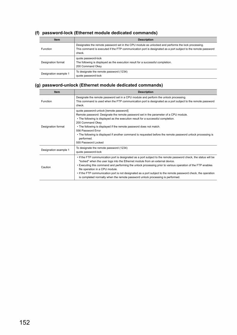
(f) password-lock (Ethernet module dedicated commands)
(g) password-unlock (Ethernet module dedicated commands)
Item Description
Function
Designates the remote password set in the CPU module as unlocked and performs the lock processing.
This command is executed if the FTP communication port is designated as a port subject to the remote password
check.
Designation format
quote password-lock
The following is displayed as the execution result for a successful completion.
200 Command Okey
Designation example 1To designate the remote password (1234)
quote password-lock
Item Description
Function
Designate the remote password set in a CPU module and perform the unlock processing.
This command is used when the FTP communication port is designated as a port subject to the remote password
check.
Designation format
quote password-unlock [remote password]
Remote password: Designate the remote password set in the parameter of a CPU module.
• The following is displayed as the execution result for a successful completion.
200 Command Okey
• The following is displayed if the remote password does not match.
556 Password Error
• The following is displayed if another command is requested before the remote password unlock processing is
performed.
555 Password Locked
Designation example 1To designate the remote password (1234)
quote password-lock
Caution
• If the FTP communication port is designated as a port subject to the remote password check, the status will be
"locked" when the user logs into the Ethernet module from an external device.
• Executing this command and performing the unlock processing prior to various operation of the FTP enables
file operation in a CPU module.
• If the FTP communication port is not designated as a port subject to the remote password check, the operation
is completed normally when the remote password unlock processing is performed.
152
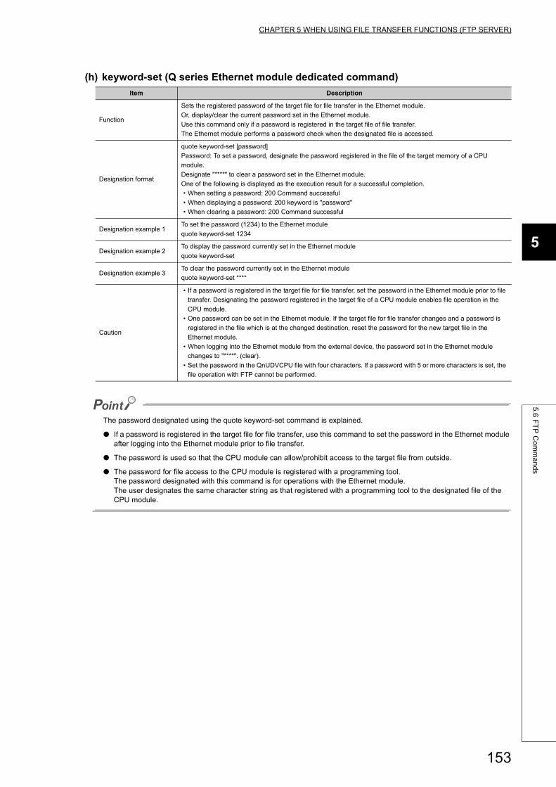
CHAPTER 5 WHEN USING FILE TRANSFER FUNCTIONS (FTP SERVER)
5
5.6
FT
P C
om
ma
nd
s
(h) keyword-set (Q series Ethernet module dedicated command)
The password designated using the quote keyword-set command is explained.
● If a password is registered in the target file for file transfer, use this command to set the password in the Ethernet module after logging into the Ethernet module prior to file transfer.
● The password is used so that the CPU module can allow/prohibit access to the target file from outside.
● The password for file access to the CPU module is registered with a programming tool.The password designated with this command is for operations with the Ethernet module.The user designates the same character string as that registered with a programming tool to the designated file of the CPU module.
Item Description
Function
Sets the registered password of the target file for file transfer in the Ethernet module.
Or, display/clear the current password set in the Ethernet module.
Use this command only if a password is registered in the target file of file transfer.
The Ethernet module performs a password check when the designated file is accessed.
Designation format
quote keyword-set [password]
Password: To set a password, designate the password registered in the file of the target memory of a CPU
module.
Designate "****" to clear a password set in the Ethernet module.
One of the following is displayed as the execution result for a successful completion.
• When setting a password: 200 Command successful
• When displaying a password: 200 keyword is "password"
• When clearing a password: 200 Command successful
Designation example 1To set the password (1234) to the Ethernet module
quote keyword-set 1234
Designation example 2To display the password currently set in the Ethernet module
quote keyword-set
Designation example 3To clear the password currently set in the Ethernet module
quote keyword-set ****
Caution
• If a password is registered in the target file for file transfer, set the password in the Ethernet module prior to file
transfer. Designating the password registered in the target file of a CPU module enables file operation in the
CPU module.
• One password can be set in the Ethernet module. If the target file for file transfer changes and a password is
registered in the file which is at the changed destination, reset the password for the new target file in the
Ethernet module.
• When logging into the Ethernet module from the external device, the password set in the Ethernet module
changes to "****". (clear).
• Set the password in the QnUDVCPU file with four characters. If a password with 5 or more characters is set, the
file operation with FTP cannot be performed.
153
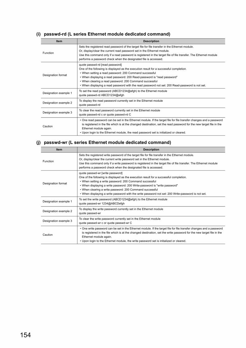
(i) passwd-rd (L series Ethernet module dedicated command)
(j) passwd-wr (L series Ethernet module dedicated command)
Item Description
Function
Sets the registered read password of the target file for file transfer in the Ethernet module.
Or, display/clear the current read password set in the Ethernet module.
Use this command only if a read password is registered in the target file of file transfer. The Ethernet module
performs a password check when the designated file is accessed.
Designation format
quote passwd-rd [read password]
One of the following is displayed as the execution result for a successful completion.
• When setting a read password: 200 Command successful
• When displaying a read password: 200 Read-password is "read password"
• When clearing a read password: 200 Command successful
• When displaying a read password with the read password not set: 200 Read-password is not set.
Designation example 1To set the read password (ABCD1234@efgh) to the Ethernet module
quote passwd-rd ABCD1234@efgh
Designation example 2To display the read password currently set in the Ethernet module
quote passwd-rd
Designation example 3To clear the read password currently set in the Ethernet module
quote passwd-rd c or quote passwd-rd C
Caution
• One read password can be set in the Ethernet module. If the target file for file transfer changes and a password
is registered in the file which is at the changed destination, set the read password for the new target file in the
Ethernet module again.
• Upon login to the Ethernet module, the read password set is initialized or cleared.
Item Description
Function
Sets the registered write password of the target file for file transfer in the Ethernet module.
Or, display/clear the current write password set in the Ethernet module.
Use this command only if a write password is registered in the target file of file transfer. The Ethernet module
performs a password check when the designated file is accessed.
Designation format
quote passwd-wr [write password]
One of the following is displayed as the execution result for a successful completion.
• When setting a write password: 200 Command successful
• When displaying a write password: 200 Write-password is "write password"
• When clearing a write password: 200 Command successful
• When displaying a write password with the write password not set: 200 Write-password is not set.
Designation example 1To set the write password (ABCD1234@efgh) to the Ethernet module
quote passwd-wr 1234@ABCDefgh
Designation example 2To display the write password currently set in the Ethernet module
quote passwd-wr
Designation example 3To clear the write password currently set in the Ethernet module
quote passwd-wr c or quote passwd-wr C
Caution
• One write password can be set in the Ethernet module. If the target file for file transfer changes and a password
is registered in the file which is at the changed destination, set the write password for the new target file in the
Ethernet module again.
• Upon login to the Ethernet module, the write password set is initialized or cleared.
154
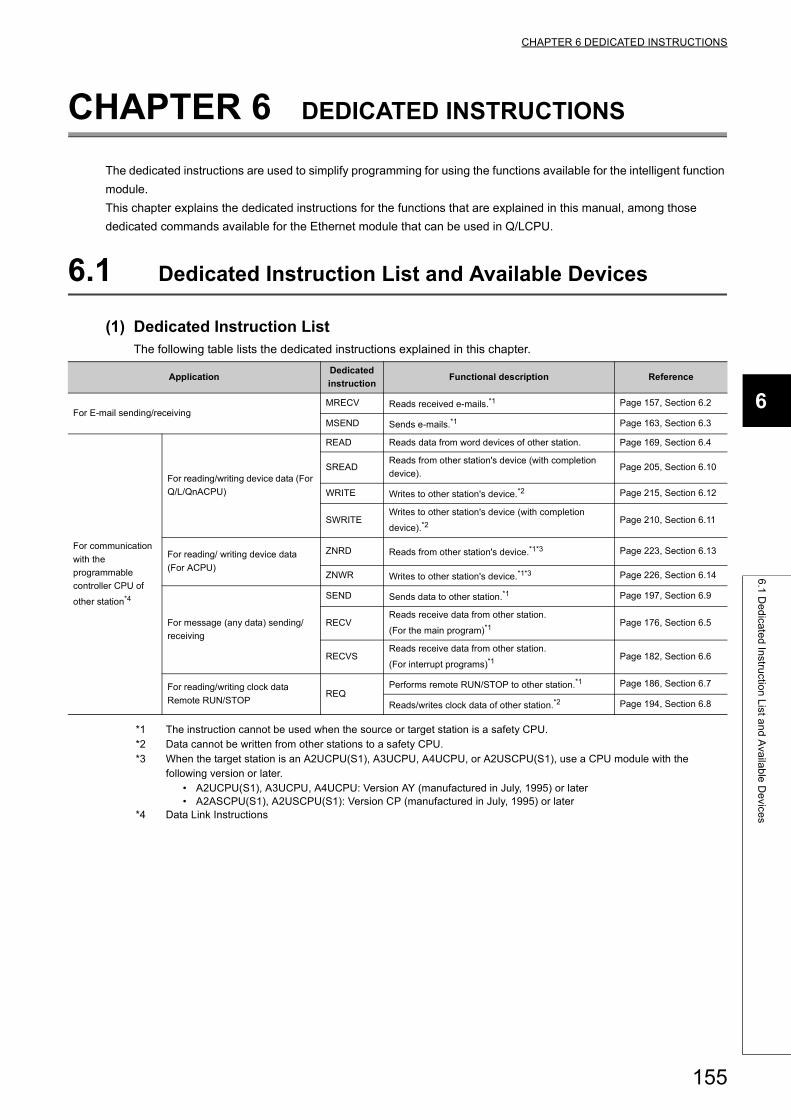
CHAPTER 6 DEDICATED INSTRUCTIONS
6
6.1
De
dica
ted
Instru
ction
List a
nd
Ava
ilab
le D
evice
s
CHAPTER 6 DEDICATED INSTRUCTIONS
The dedicated instructions are used to simplify programming for using the functions available for the intelligent function
module.
This chapter explains the dedicated instructions for the functions that are explained in this manual, among those
dedicated commands available for the Ethernet module that can be used in Q/LCPU.
6.1 Dedicated Instruction List and Available Devices
(1) Dedicated Instruction ListThe following table lists the dedicated instructions explained in this chapter.
*1 The instruction cannot be used when the source or target station is a safety CPU.*2 Data cannot be written from other stations to a safety CPU.*3 When the target station is an A2UCPU(S1), A3UCPU, A4UCPU, or A2USCPU(S1), use a CPU module with the
following version or later.• A2UCPU(S1), A3UCPU, A4UCPU: Version AY (manufactured in July, 1995) or later• A2ASCPU(S1), A2USCPU(S1): Version CP (manufactured in July, 1995) or later
*4 Data Link Instructions
ApplicationDedicated
instructionFunctional description Reference
For E-mail sending/receivingMRECV Reads received e-mails.*1 Page 157, Section 6.2
MSEND Sends e-mails.*1 Page 163, Section 6.3
For communication
with the
programmable
controller CPU of
other station*4
For reading/writing device data (For
Q/L/QnACPU)
READ Reads data from word devices of other station. Page 169, Section 6.4
SREADReads from other station's device (with completion
device).Page 205, Section 6.10
WRITE Writes to other station's device.*2 Page 215, Section 6.12
SWRITEWrites to other station's device (with completion
device).*2Page 210, Section 6.11
For reading/ writing device data
(For ACPU)
ZNRD Reads from other station's device.*1*3 Page 223, Section 6.13
ZNWR Writes to other station's device.*1*3 Page 226, Section 6.14
For message (any data) sending/
receiving
SEND Sends data to other station.*1 Page 197, Section 6.9
RECVReads receive data from other station.
(For the main program)*1Page 176, Section 6.5
RECVSReads receive data from other station.
(For interrupt programs)*1Page 182, Section 6.6
For reading/writing clock data
Remote RUN/STOPREQ
Performs remote RUN/STOP to other station.*1 Page 186, Section 6.7
Reads/writes clock data of other station.*2 Page 194, Section 6.8
155
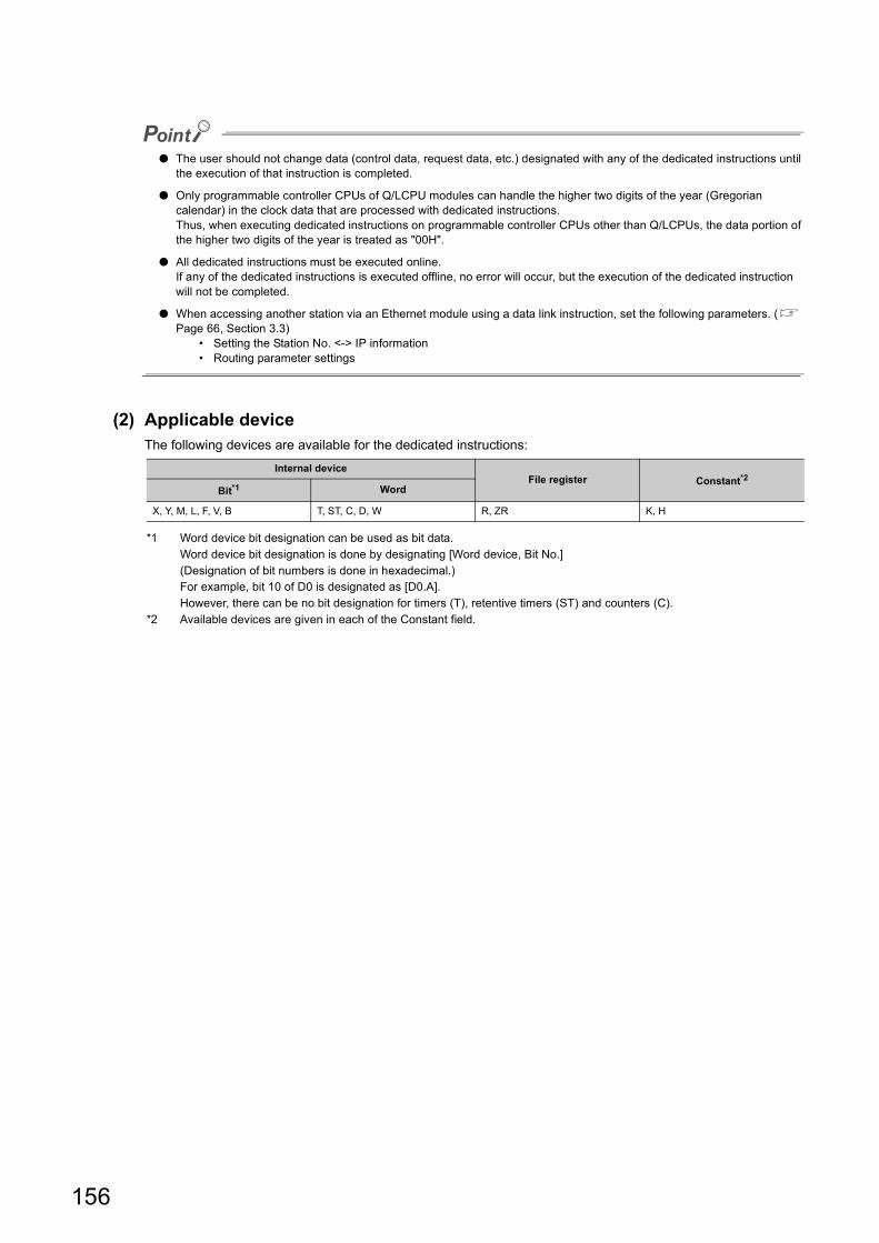
● The user should not change data (control data, request data, etc.) designated with any of the dedicated instructions until the execution of that instruction is completed.
● Only programmable controller CPUs of Q/LCPU modules can handle the higher two digits of the year (Gregorian calendar) in the clock data that are processed with dedicated instructions.Thus, when executing dedicated instructions on programmable controller CPUs other than Q/LCPUs, the data portion of the higher two digits of the year is treated as "00H".
● All dedicated instructions must be executed online.If any of the dedicated instructions is executed offline, no error will occur, but the execution of the dedicated instruction will not be completed.
● When accessing another station via an Ethernet module using a data link instruction, set the following parameters. ( Page 66, Section 3.3)
• Setting the Station No. <-> IP information• Routing parameter settings
(2) Applicable deviceThe following devices are available for the dedicated instructions:
*1 Word device bit designation can be used as bit data.Word device bit designation is done by designating [Word device, Bit No.](Designation of bit numbers is done in hexadecimal.)For example, bit 10 of D0 is designated as [D0.A].However, there can be no bit designation for timers (T), retentive timers (ST) and counters (C).
*2 Available devices are given in each of the Constant field.
Internal deviceFile register Constant*2
Bit*1 Word
X, Y, M, L, F, V, B T, ST, C, D, W R, ZR K, H
156
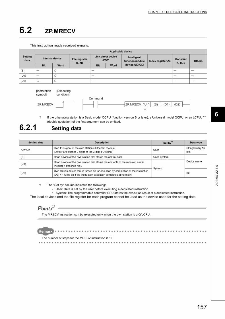
CHAPTER 6 DEDICATED INSTRUCTIONS
6
6.2
ZP
.MR
EC
V
6.2 ZP.MRECV
This instruction reads received e-mails.
*1 If the originating station is a Basic model QCPU (function version B or later), a Universal model QCPU, or an LCPU, " " (double quotation) of the first argument can be omitted.
6.2.1 Setting data
*1 The "Set by" column indicates the following:• User: Data is set by the user before executing a dedicated instruction.• System: The programmable controller CPU stores the execution result of a dedicated instruction.
The local devices and the file register for each program cannot be used as the device used for the setting data.
The MRECV instruction can be executed only when the own station is a Q/LCPU.
Remark
The number of steps for the MRECV instruction is 10.
Setting
data
Applicable device
Internal device File register
R, ZR
Link direct device
J\Intelligent
function module
device U\G
Index register ZnConstant
K, H, $Others
Bit Word Bit Word
(S)
(D1)
(D2)
Setting data Description Set by*1 Data type
"Un"/UnStart I/O signal of the own station's Ethernet module
(00 to FEH: Higher 2 digits of the 3-digit I/O signal)User
String/Binary 16
bits
(S) Head device of the own station that stores the control data. User, system
Device name(D1)
Head device of the own station that stores the contents of the received e-mail
(header + attached file).System
(D2)Own station device that is turned on for one scan by completion of the instruction.
(D2) + 1 turns on if the instruction execution completes abnormally.Bit
ZP.MRECV (D2)ZP.MRECV (D1)(S)"Un"
[Executing condition]
[Instruction symbol]
*1
Command
157
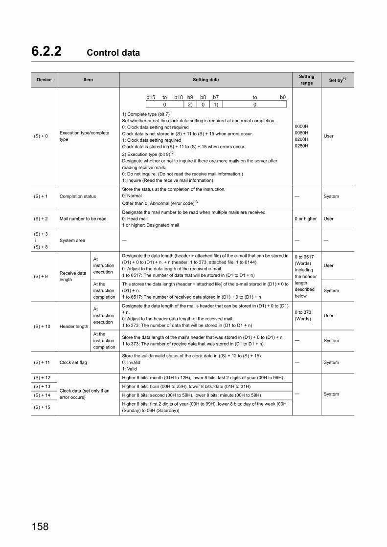
6.2.2 Control data
Device Item Setting dataSetting
rangeSet by*1
(S) + 0Execution type/complete
type
1) Complete type (bit 7)
Set whether or not the clock data setting is required at abnormal completion.
0: Clock data setting not required
Clock data is not stored in (S) + 11 to (S) + 15 when errors occur.
1: Clock data setting required
Clock data is stored in (S) + 11 to (S) + 15 when errors occur.
2) Execution type (bit 9)*2
Designate whether or not to inquire if there are more mails on the server after
reading receive mails.
0: Do not inquire. (Do not read the receive mail information.)
1: Inquire (Read the receive mail information)
0000H
0080H
0200H
0280H
User
(S) + 1 Completion status
Store the status at the completion of the instruction.
0: Normal
Other than 0: Abnormal (error code)*3 System
(S) + 2 Mail number to be read
Designate the mail number to be read when multiple mails are received.
0: Head mail
1 or higher: Designated mail
0 or higher User
(S) + 3
(S) + 8
System area
(S) + 9Receive data
length
At
instruction
execution
Designate the data length (header + attached file) of the e-mail that can be stored in
(D1) + 0 to (D1) + n. + n (header: 1 to 373, attached file: 1 to 6144).
0: Adjust to the data length of the received e-mail.
1 to 6517: The number of data that will be stored in (D1 to D1 + n)
0 to 6517
(Words)
Including
the header
length
described
below
User
At the
instruction
completion
This stores the data length (header + attached file) of the e-mail stored in (D1) + 0 to
(D1) + n.
1 to 6517: The number of received data stored in (D1) + 0 to (D1) + n
System
(S) + 10 Header length
At
instruction
execution
Designate the data length of the mail's header that can be stored in (D1) + 0 to (D1)
+ n.
0: Adjust to the header data length of the received mail.
1 to 373: The number of data that will be stored in (D1 to D1 + n)
0 to 373
(Words)User
At the
instruction
completion
Store the data length of the mail's header that was stored in (D1) + 0 to (D1) + n.
1 to 373: The number of receive data that was stored in (D1 to D1 + n). System
(S) + 11 Clock set flag
Store the valid/invalid status of the clock data in ((S) + 12 to (S) + 15).
0: Invalid
1: Valid
System
(S) + 12
Clock data (set only if an
error occurs)
Higher 8 bits: month (01H to 12H), lower 8 bits: last 2 digits of year (00H to 99H)
System
(S) + 13 Higher 8 bits: hour (00H to 23H), lower 8 bits: date (01H to 31H)
(S) + 14 Higher 8 bits: second (00H to 59H), lower 8 bits: minute (00H to 59H)
(S) + 15Higher 8 bits: first 2 digits of year (00H to 99H), lower 8 bits: day of the week (00H
(Sunday) to 06H (Saturday))
b8b9b1002) 1) 00
b0b7b15 toto
158
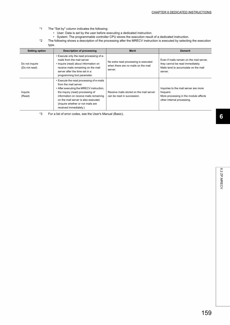
CHAPTER 6 DEDICATED INSTRUCTIONS
6
6.2
ZP
.MR
EC
V
*1 The "Set by" column indicates the following:• User: Data is set by the user before executing a dedicated instruction.• System: The programmable controller CPU stores the execution result of a dedicated instruction.
*2 The following shows a description of the processing after the MRECV instruction is executed by selecting the execution type.
*3 For a list of error codes, see the User's Manual (Basic).
Setting option Description of processing Merit Demerit
Do not inquire
(Do not read)
• Execute only the read processing of e-
mails from the mail server.
• Inquire (read) about information on
receive mails remaining on the mail
server after the time set in a
programming tool parameter.
No extra read processing is executed
when there are no mails on the mail
server.
Even if mails remain on the mail server,
they cannot be read immediately.
Mails tend to accumulate on the mail
server.
Inquire
(Read)
• Execute the read processing of e-mails
from the mail server.
• After executing the MRECV instruction,
the inquiry (read) processing of
information on receive mails remaining
on the mail server is also executed.
(Inquire whether or not mails are
received immediately.)
Receive mails stored on the mail server
can be read in succession.
Inquiries to the mail server are more
frequent.
More processing in the module affects
other internal processing.
159
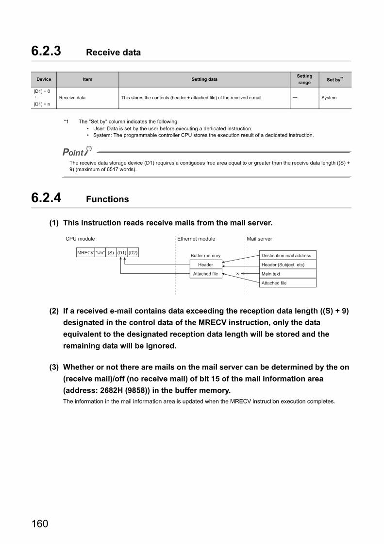
6.2.3 Receive data
*1 The "Set by" column indicates the following:• User: Data is set by the user before executing a dedicated instruction.• System: The programmable controller CPU stores the execution result of a dedicated instruction.
The receive data storage device (D1) requires a contiguous free area equal to or greater than the receive data length ((S) + 9) (maximum of 6517 words).
6.2.4 Functions
(1) This instruction reads receive mails from the mail server.
(2) If a received e-mail contains data exceeding the reception data length ((S) + 9)
designated in the control data of the MRECV instruction, only the data
equivalent to the designated reception data length will be stored and the
remaining data will be ignored.
(3) Whether or not there are mails on the mail server can be determined by the on
(receive mail)/off (no receive mail) of bit 15 of the mail information area
(address: 2682H (9858)) in the buffer memory.The information in the mail information area is updated when the MRECV instruction execution completes.
Device Item Setting dataSetting
rangeSet by*1
(D1) + 0
(D1) + n
Receive data This stores the contents (header + attached file) of the received e-mail. System
(D2)"Un" (D1)(S)MRECV
×
Attached file
Main text
Header (Subject, etc)
Destination mail address
Mail server
Attached file
Ethernet moduleCPU module
Buffer memory
Header
160
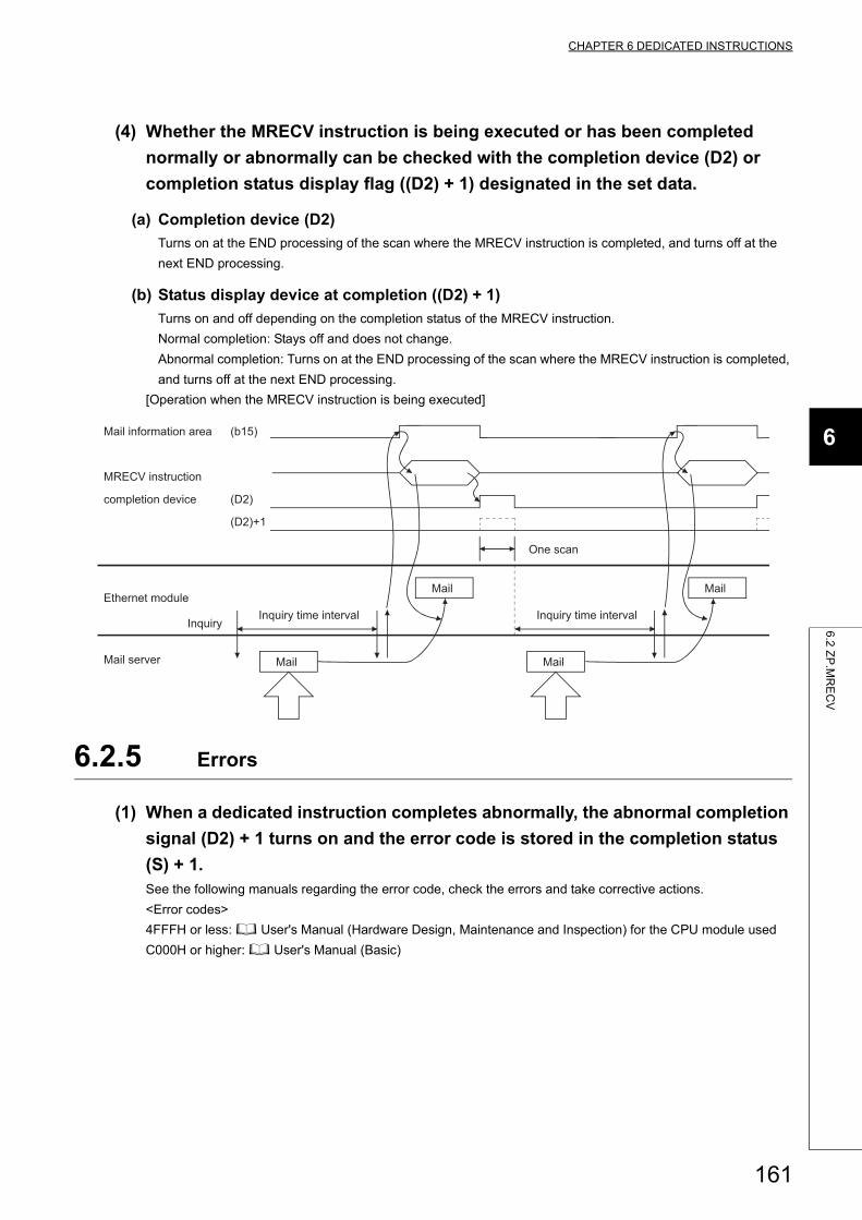
CHAPTER 6 DEDICATED INSTRUCTIONS
6
6.2
ZP
.MR
EC
V
(4) Whether the MRECV instruction is being executed or has been completed
normally or abnormally can be checked with the completion device (D2) or
completion status display flag ((D2) + 1) designated in the set data.
(a) Completion device (D2)
Turns on at the END processing of the scan where the MRECV instruction is completed, and turns off at the
next END processing.
(b) Status display device at completion ((D2) + 1)
Turns on and off depending on the completion status of the MRECV instruction.
Normal completion: Stays off and does not change.
Abnormal completion: Turns on at the END processing of the scan where the MRECV instruction is completed,
and turns off at the next END processing.
[Operation when the MRECV instruction is being executed]
6.2.5 Errors
(1) When a dedicated instruction completes abnormally, the abnormal completion
signal (D2) + 1 turns on and the error code is stored in the completion status
(S) + 1.See the following manuals regarding the error code, check the errors and take corrective actions.
<Error codes>
4FFFH or less: User's Manual (Hardware Design, Maintenance and Inspection) for the CPU module used
C000H or higher: User's Manual (Basic)
(D2)+1
(D2)
(b15)
Inquiry time intervalInquiry time intervalEthernet module
completion device
MRECV instruction
MailMail server
Inquiry
One scan
Mail information area
161
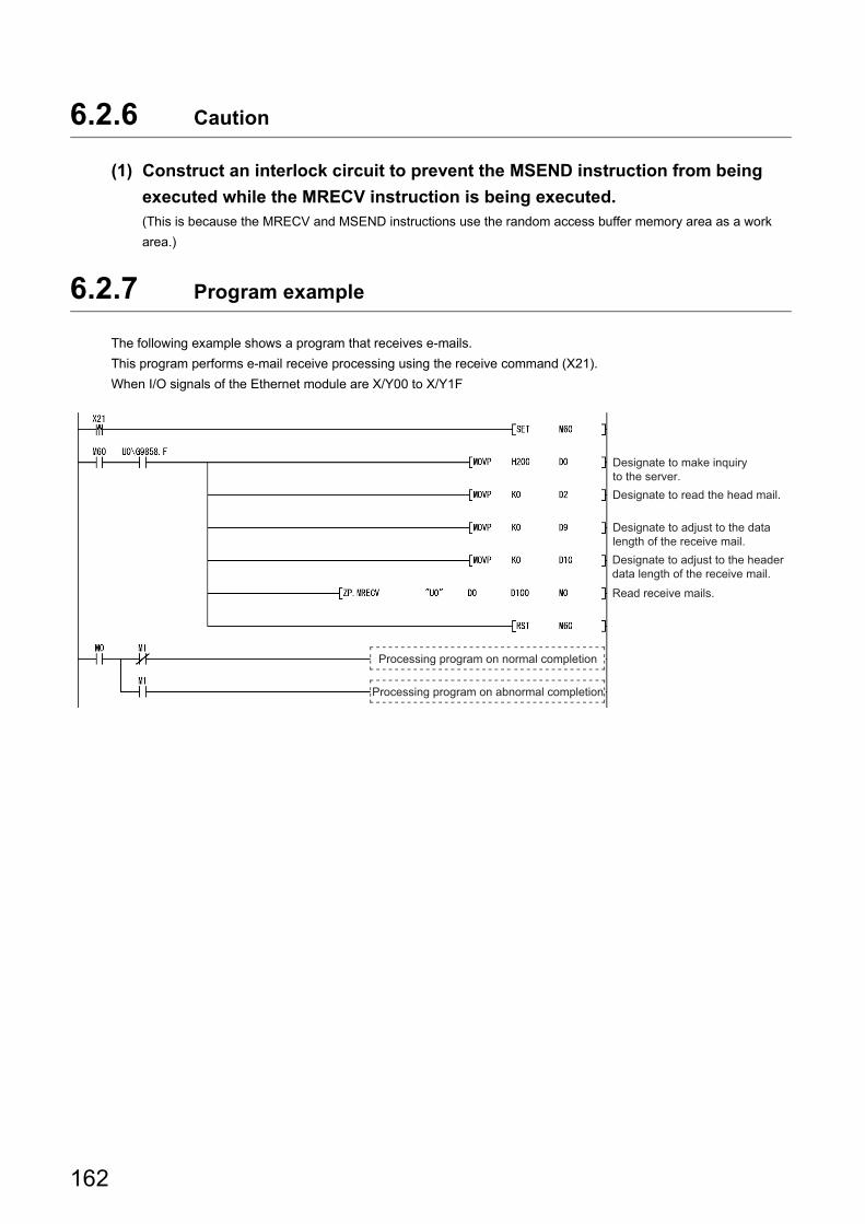
6.2.6 Caution
(1) Construct an interlock circuit to prevent the MSEND instruction from being
executed while the MRECV instruction is being executed.(This is because the MRECV and MSEND instructions use the random access buffer memory area as a work
area.)
6.2.7 Program example
The following example shows a program that receives e-mails.
This program performs e-mail receive processing using the receive command (X21).
When I/O signals of the Ethernet module are X/Y00 to X/Y1F
Processing program on abnormal completion
Processing program on normal completion
Designate to adjust to the header data length of the receive mail.
Designate to adjust to the data length of the receive mail.
Designate to read the head mail.
Designate to make inquiry to the server.
Read receive mails.
162
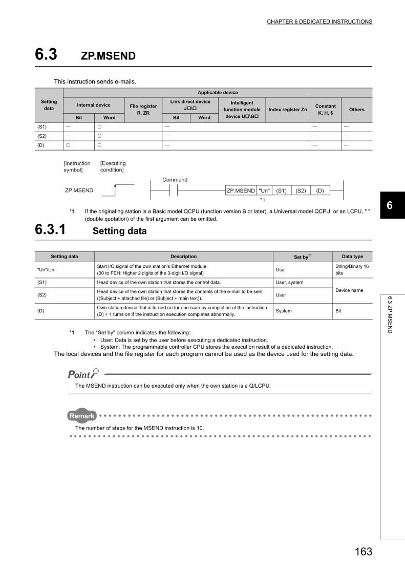
CHAPTER 6 DEDICATED INSTRUCTIONS
6
6.3
ZP
.MS
EN
D
6.3 ZP.MSEND
This instruction sends e-mails.
*1 If the originating station is a Basic model QCPU (function version B or later), a Universal model QCPU, or an LCPU, " " (double quotation) of the first argument can be omitted.
6.3.1 Setting data
*1 The "Set by" column indicates the following:• User: Data is set by the user before executing a dedicated instruction.• System: The programmable controller CPU stores the execution result of a dedicated instruction.
The local devices and the file register for each program cannot be used as the device used for the setting data.
The MSEND instruction can be executed only when the own station is a Q/LCPU.
Remark
The number of steps for the MSEND instruction is 10.
Setting
data
Applicable device
Internal device File register
R, ZR
Link direct device
J\Intelligent
function module
device U\G
Index register ZnConstant
K, H, $Others
Bit Word Bit Word
(S1)
(S2)
(D)
Setting data Description Set by*1 Data type
"Un"/UnStart I/O signal of the own station's Ethernet module
(00 to FEH: Higher 2 digits of the 3-digit I/O signal)User
String/Binary 16
bits
(S1) Head device of the own station that stores the control data. User, system
Device name(S2)
Head device of the own station that stores the contents of the e-mail to be sent
((Subject + attached file) or (Subject + main text)).User
(D)Own station device that is turned on for one scan by completion of the instruction.
(D) + 1 turns on if the instruction execution completes abnormally.System Bit
ZP.MSEND (D)ZP.MSEND (S2)(S1)"Un"
[Executing condition]
[Instruction symbol]
*1
Command
163
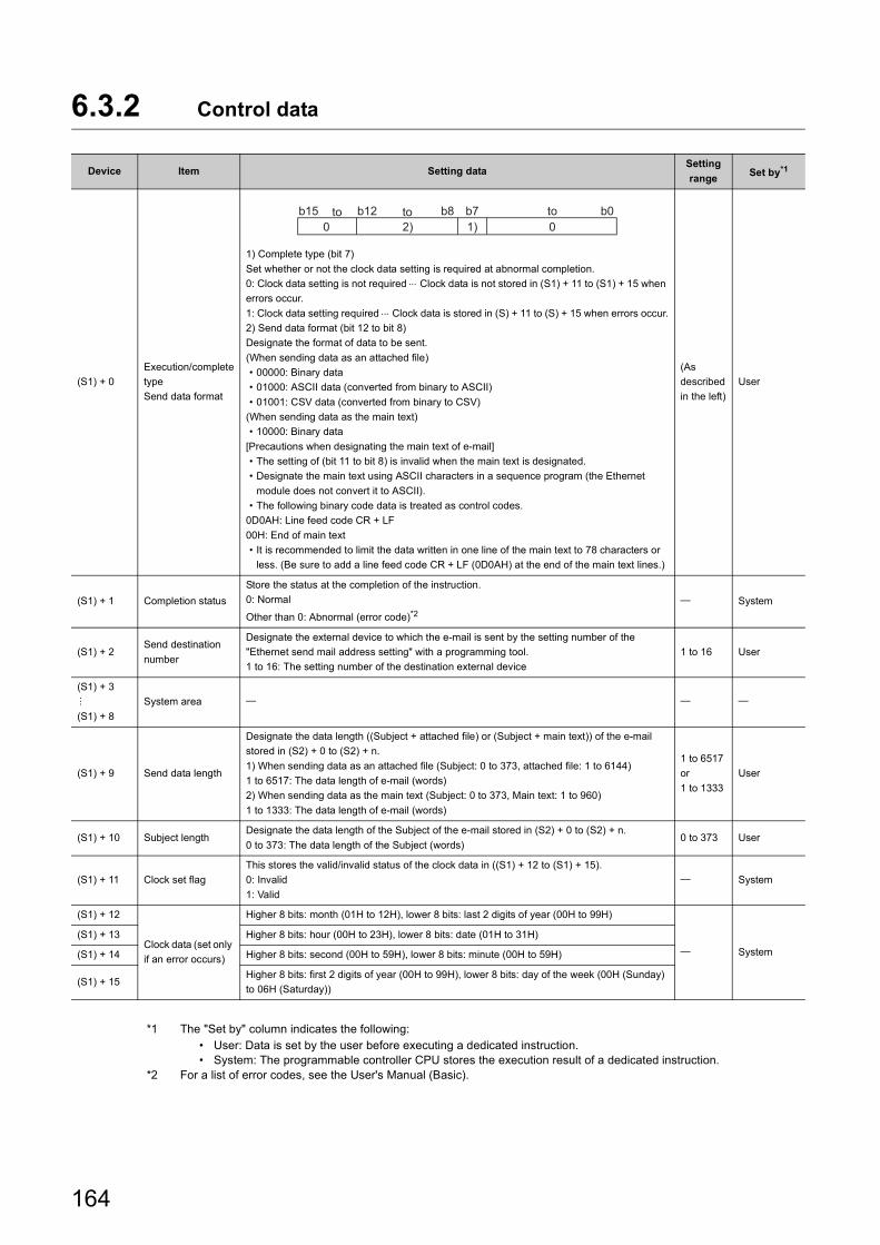
6.3.2 Control data
*1 The "Set by" column indicates the following:• User: Data is set by the user before executing a dedicated instruction.• System: The programmable controller CPU stores the execution result of a dedicated instruction.
*2 For a list of error codes, see the User's Manual (Basic).
Device Item Setting dataSetting
rangeSet by*1
(S1) + 0
Execution/complete
type
Send data format
1) Complete type (bit 7)
Set whether or not the clock data setting is required at abnormal completion.
0: Clock data setting is not required Clock data is not stored in (S1) + 11 to (S1) + 15 when
errors occur.
1: Clock data setting required Clock data is stored in (S) + 11 to (S) + 15 when errors occur.
2) Send data format (bit 12 to bit 8)
Designate the format of data to be sent.
(When sending data as an attached file)
• 00000: Binary data
• 01000: ASCII data (converted from binary to ASCII)
• 01001: CSV data (converted from binary to CSV)
(When sending data as the main text)
• 10000: Binary data
[Precautions when designating the main text of e-mail]
• The setting of (bit 11 to bit 8) is invalid when the main text is designated.
• Designate the main text using ASCII characters in a sequence program (the Ethernet
module does not convert it to ASCII).
• The following binary code data is treated as control codes.
0D0AH: Line feed code CR + LF
00H: End of main text
• It is recommended to limit the data written in one line of the main text to 78 characters or
less. (Be sure to add a line feed code CR + LF (0D0AH) at the end of the main text lines.)
(As
described
in the left)
User
(S1) + 1 Completion status
Store the status at the completion of the instruction.
0: Normal
Other than 0: Abnormal (error code)*2 System
(S1) + 2Send destination
number
Designate the external device to which the e-mail is sent by the setting number of the
"Ethernet send mail address setting" with a programming tool.
1 to 16: The setting number of the destination external device
1 to 16 User
(S1) + 3
(S1) + 8
System area
(S1) + 9 Send data length
Designate the data length ((Subject + attached file) or (Subject + main text)) of the e-mail
stored in (S2) + 0 to (S2) + n.
1) When sending data as an attached file (Subject: 0 to 373, attached file: 1 to 6144)
1 to 6517: The data length of e-mail (words)
2) When sending data as the main text (Subject: 0 to 373, Main text: 1 to 960)
1 to 1333: The data length of e-mail (words)
1 to 6517
or
1 to 1333
User
(S1) + 10 Subject lengthDesignate the data length of the Subject of the e-mail stored in (S2) + 0 to (S2) + n.
0 to 373: The data length of the Subject (words)0 to 373 User
(S1) + 11 Clock set flag
This stores the valid/invalid status of the clock data in ((S1) + 12 to (S1) + 15).
0: Invalid
1: Valid
System
(S1) + 12
Clock data (set only
if an error occurs)
Higher 8 bits: month (01H to 12H), lower 8 bits: last 2 digits of year (00H to 99H)
System
(S1) + 13 Higher 8 bits: hour (00H to 23H), lower 8 bits: date (01H to 31H)
(S1) + 14 Higher 8 bits: second (00H to 59H), lower 8 bits: minute (00H to 59H)
(S1) + 15Higher 8 bits: first 2 digits of year (00H to 99H), lower 8 bits: day of the week (00H (Sunday)
to 06H (Saturday))
b12 b800 2) 1)
b0b7b15 to to to
164
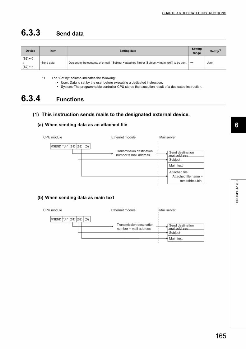
CHAPTER 6 DEDICATED INSTRUCTIONS
6
6.3
ZP
.MS
EN
D
6.3.3 Send data
*1 The "Set by" column indicates the following:• User: Data is set by the user before executing a dedicated instruction.• System: The programmable controller CPU stores the execution result of a dedicated instruction.
6.3.4 Functions
(1) This instruction sends mails to the designated external device.
(a) When sending data as an attached file
(b) When sending data as main text
Device Item Setting dataSetting
rangeSet by*1
(S2) + 0
(S2) + n
Send data Designate the contents of e-mail ((Subject + attached file) or (Subject + main text)) to be sent. User
(S1)"Un" (D)(S2)MSEND
Attached file name =Attached file
Main text
Send destination mail address
Mail server
Transmission destination number = mail address
Ethernet moduleCPU module
mmddhhss.bin
Subject
"Un" (D)(S2)(S1)MSEND
Main text
Send destination mail address
Mail server
Transmission destination number = mail address
Ethernet moduleCPU module
Subject
165
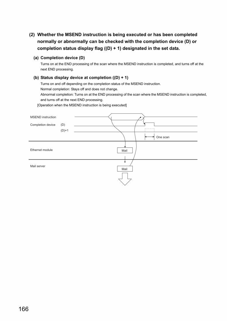
(2) Whether the MSEND instruction is being executed or has been completed
normally or abnormally can be checked with the completion device (D) or
completion status display flag ((D) + 1) designated in the set data.
(a) Completion device (D)
Turns on at the END processing of the scan where the MSEND instruction is completed, and turns off at the
next END processing.
(b) Status display device at completion ((D) + 1)
Turns on and off depending on the completion status of the MSEND instruction.
Normal completion: Stays off and does not change.
Abnormal completion: Turns on at the END processing of the scan where the MSEND instruction is completed,
and turns off at the next END processing.
[Operation when the MSEND instruction is being executed]
(D)+1
(D)
One scan
Ethernet module
Completion device
MSEND instruction
MailMail server
166
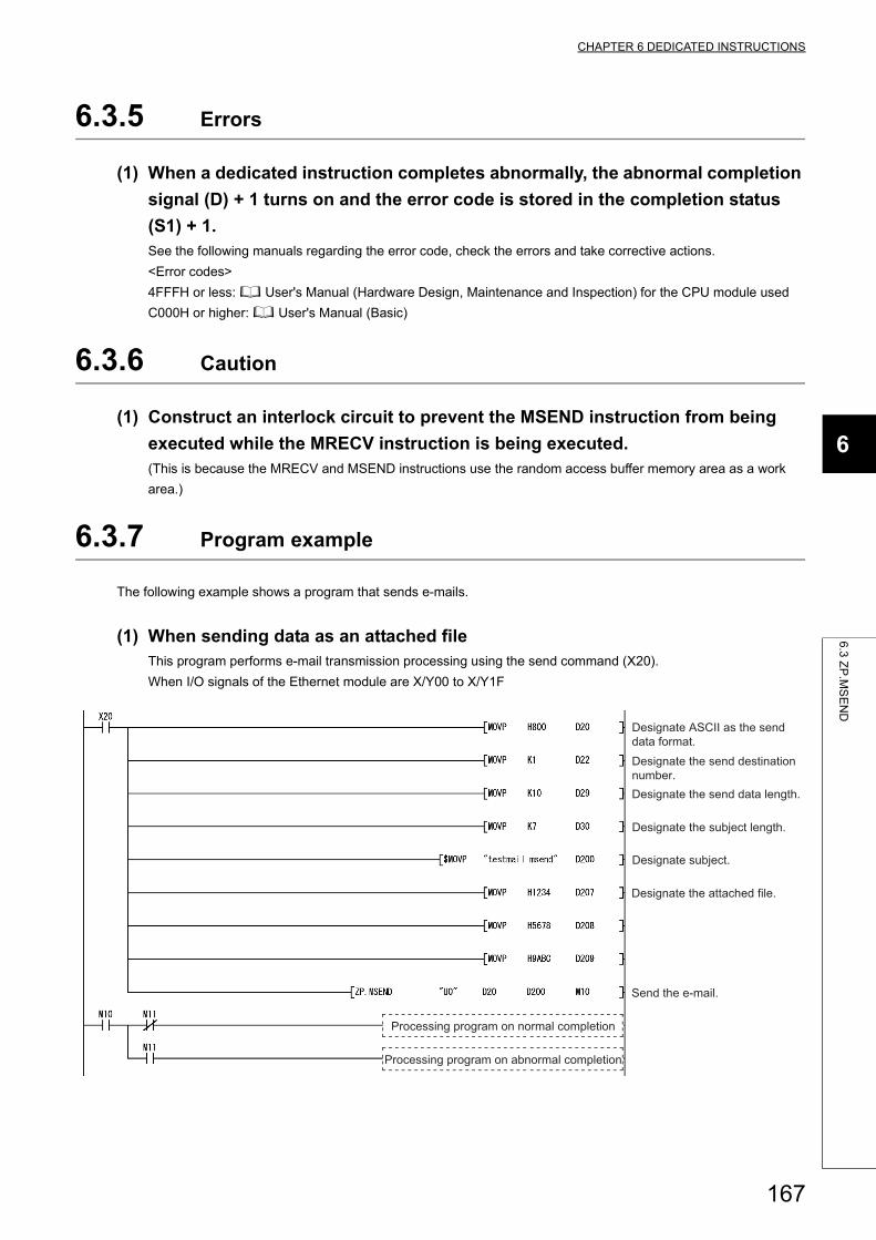
CHAPTER 6 DEDICATED INSTRUCTIONS
6
6.3
ZP
.MS
EN
D
6.3.5 Errors
(1) When a dedicated instruction completes abnormally, the abnormal completion
signal (D) + 1 turns on and the error code is stored in the completion status
(S1) + 1.See the following manuals regarding the error code, check the errors and take corrective actions.
<Error codes>
4FFFH or less: User's Manual (Hardware Design, Maintenance and Inspection) for the CPU module used
C000H or higher: User's Manual (Basic)
6.3.6 Caution
(1) Construct an interlock circuit to prevent the MSEND instruction from being
executed while the MRECV instruction is being executed.(This is because the MRECV and MSEND instructions use the random access buffer memory area as a work
area.)
6.3.7 Program example
The following example shows a program that sends e-mails.
(1) When sending data as an attached fileThis program performs e-mail transmission processing using the send command (X20).
When I/O signals of the Ethernet module are X/Y00 to X/Y1F
Processing program on abnormal completion
Processing program on normal completion
Send the e-mail.
Designate the attached file.
Designate subject.
Designate the subject length.
Designate the send data length.
Designate the send destination number.
Designate ASCII as the send data format.
167
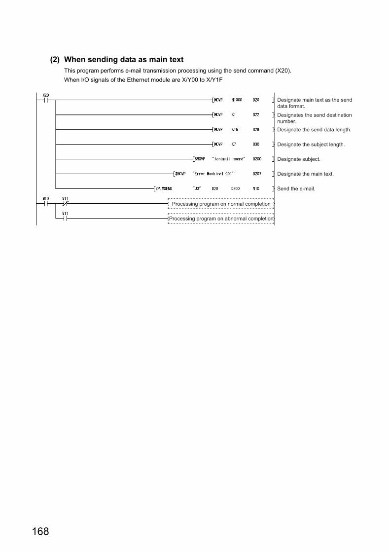
(2) When sending data as main textThis program performs e-mail transmission processing using the send command (X20).
When I/O signals of the Ethernet module are X/Y00 to X/Y1F
Processing program on abnormal completion
Processing program on normal completion
Send the e-mail.
Designate the main text.
Designate subject.
Designate the subject length.
Designate the send data length.
Designates the send destination number.
Designate main text as the send data format.
168
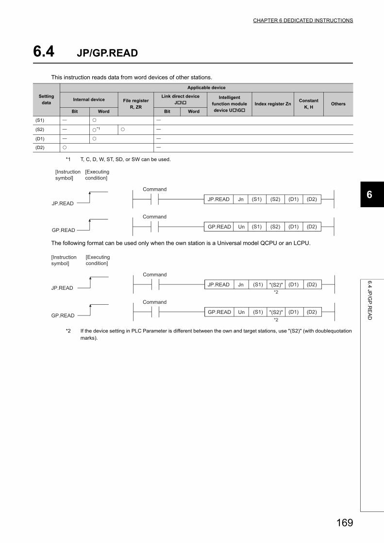
CHAPTER 6 DEDICATED INSTRUCTIONS
6
6.4
JP/G
P.R
EA
D
6.4 JP/GP.READ
This instruction reads data from word devices of other stations.
*1 T, C, D, W, ST, SD, or SW can be used.
The following format can be used only when the own station is a Universal model QCPU or an LCPU.
*2 If the device setting in PLC Parameter is different between the own and target stations, use "(S2)" (with doublequotation marks).
Setting
data
Applicable device
Internal device File register
R, ZR
Link direct device
J\Intelligent
function module
device U\G
Index register ZnConstant
K, HOthers
Bit Word Bit Word
(S1)
(S2) *1
(D1)
(D2)
(D2)(D1)(S2)(S1)UnGP.READ
GP.READ
(D2)JP.READ
(D1)(S2)(S1)JnJP.READ
[Executing condition]
[Instruction symbol]
Command
Command
"(S2)" (D2)(D1)(S1)UnGP.READ
GP.READ
(D2)JP.READ
(D1)"(S2)"(S1)JnJP.READ*2
*2
[Executing condition]
[Instruction symbol]
Command
Command
169
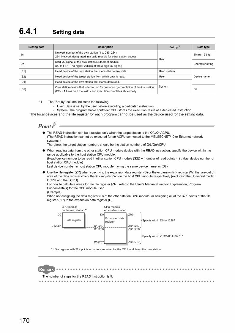
6.4.1 Setting data
*1 The "Set by" column indicates the following:• User: Data is set by the user before executing a dedicated instruction.• System: The programmable controller CPU stores the execution result of a dedicated instruction.
The local devices and the file register for each program cannot be used as the device used for the setting data.
● The READ instruction can be executed only when the target station is the Q/L/QnACPU.(The READ instruction cannot be executed for an ACPU connected to the MELSECNET/10 or Ethernet network systems.)Therefore, the target station numbers should be the station numbers of Q/L/QnACPU.
● When reading data from the other station CPU module device with the READ instruction, specify the device within the range applicable to the host station CPU module.(Head device number to be read in other station CPU module (S2)) + (number of read points -1) (last device number of host station CPU module)Last device number in host station CPU module having the same device name as (S2).
● Use the file register (ZR) when specifying the expansion data register (D) or the expansion link register (W) that are out of area of the data register (D) or the link register (W) on the host CPU module respectively (excluding the Universal model QCPU and the LCPU). For how to calculate areas for the file register (ZR), refer to the User's Manual (Function Explanation, Program Fundamentals) for the CPU module used.(Example)When not assigning the data register (D) of the other station CPU module, or assigning all of the 32K points of the file register (ZR) to the expansion data register (D).
Remark
The number of steps for the READ instruction is 9.
Setting data Description Set by*1 Data type
JnNetwork number of the own station (1 to 239, 254)
254: Network designated in a valid module for other station accessUser
Binary 16 bits
UnStart I/O signal of the own station's Ethernet module
(00 to FEH: The higher 2 digits of the 3-digit I/O signal)Character string
(S1) Head device of the own station that stores the control data. User, system
Device name(S2) Head device of the target station from which data is read. User
(D1) Head device of the own station that stores data read.
System(D2)
Own station device that is turned on for one scan by completion of the instruction.
(D2) + 1 turns on if the instruction execution completes abnormally.Bit
ZR0
ZR12287
ZR32767
ZR12288D12287
D32767
D12288D12287
D0D0
Specify within ZR12288 to 32767
Specify within D0 to 12287Expansion data register
CPU module on another station
*1 File register with 32K points or more is required for the CPU module on the own station.
CPU module on the own station *1
Data register
170
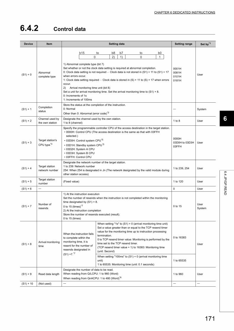
CHAPTER 6 DEDICATED INSTRUCTIONS
6
6.4
JP/G
P.R
EA
D
6.4.2 Control data
Device Item Setting data Setting range Set by*1
(S1) + 0Abnormal
complete type
1) Abnormal complete type (bit 7)
Set whether or not the clock data setting is required at abnormal completion.
0: Clock data setting is not required Clock data is not stored in (S1) + 11 to (S1) + 17
when errors occur.
1: Clock data setting required Clock data is stored in (S) + 11 to (S) + 17 when errors
occur.
2) Arrival monitoring time unit (bit 8)
Set a unit for arrival monitoring time. Set the arrival monitoring time to (S1) + 8.
0: Increments of 1s
1: Increments of 100ms
0001H
0081H
0101H
0181H
User
(S1) + 1Completion
status
Store the status at the completion of the instruction.
0: Normal
Other than 0: Abnormal (error code)*2
System
(S1) + 2Channel used by
the own station
Designate the channel used by the own station.
1 to 8 (channel)1 to 8 User
(S1) + 3Target station's
CPU type*3
Specify the programmable controller CPU of the access destination in the target station.
• 0000H: Control CPU (The access destination is the same as that with 03FFH
selected.)
• 03D0H: Control system CPU*5
• 03D1H: Standby system CPU*5
• 03D2H: System A CPU
• 03D3H: System B CPU
• 03FFH: Control CPU
0000H
03D0H to 03D3H
03FFH
User
(S1) + 4Target station
network number
Designate the network number of the target station.
1 to 239: Network number
254: When 254 is designated in Jn (The network designated by the valid module during
other station access)
1 to 239, 254 User
(S1) + 5Target station
number(Fixed value) 1 to 120 User
(S1) + 6 0 User
(S1) + 7Number of
resends
1) At the instruction execution
Set the number of resends when the instruction is not completed within the monitoring
time designated by (S1) + 8.
0 to 15 (times)*7
2) At the instruction completion
Store the number of resends executed (result).
0 to 15 (times)
0 to 15User
System
(S1) + 8Arrival monitoring
time
When the instruction fails
to complete within the
monitoring time, it is
resent for the number of
resends designated in
(S1) +7.*7
When setting "1s" to (S1) + 0 (arrival monitoring time unit)
Set a value greater than or equal to the TCP resend timer
value for the monitoring time up to instruction processing
termination.
0 to TCP resend timer value: Monitoring is performed by the
time set to the TCP resend timer.
(TCP resend timer value + 1) to 16383: Monitoring time
(unit: Second)
0 to 16383
User
When setting "100ms" to (S1) + 0 (arrival monitoring time
unit)
1 to 65535: Monitoring time (unit: 0.1 seconds)
1 to 65535
(S1) + 9 Read data length
Designate the number of data to be read.
When reading from Q/LCPU: 1 to 960 (Word)
When reading from QnACPU: 1 to 480 (Word)*61 to 960 User
(S1) + 10 (Not used)
2)b8
01) 10b0b7b15 toto
171
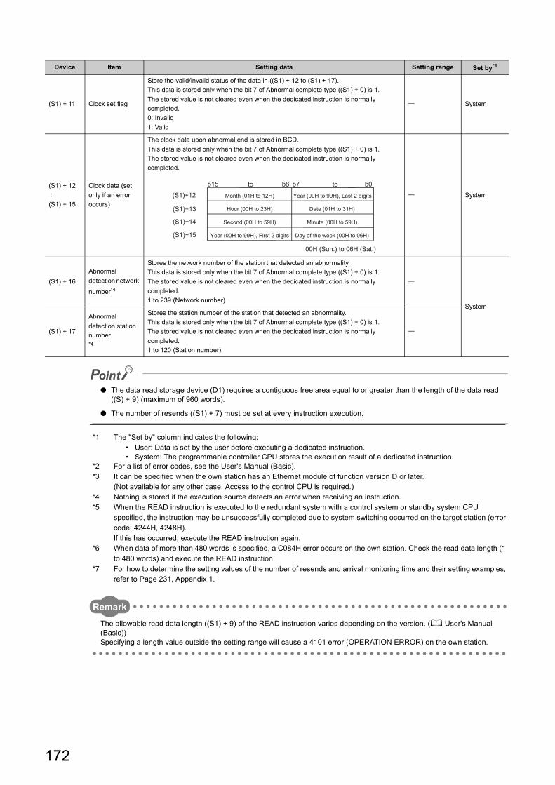
● The data read storage device (D1) requires a contiguous free area equal to or greater than the length of the data read ((S) + 9) (maximum of 960 words).
● The number of resends ((S1) + 7) must be set at every instruction execution.
*1 The "Set by" column indicates the following:• User: Data is set by the user before executing a dedicated instruction.• System: The programmable controller CPU stores the execution result of a dedicated instruction.
*2 For a list of error codes, see the User's Manual (Basic).*3 It can be specified when the own station has an Ethernet module of function version D or later.
(Not available for any other case. Access to the control CPU is required.)*4 Nothing is stored if the execution source detects an error when receiving an instruction.*5 When the READ instruction is executed to the redundant system with a control system or standby system CPU
specified, the instruction may be unsuccessfully completed due to system switching occurred on the target station (error code: 4244H, 4248H).If this has occurred, execute the READ instruction again.
*6 When data of more than 480 words is specified, a C084H error occurs on the own station. Check the read data length (1 to 480 words) and execute the READ instruction.
*7 For how to determine the setting values of the number of resends and arrival monitoring time and their setting examples, refer to Page 231, Appendix 1.
Remark
The allowable read data length ((S1) + 9) of the READ instruction varies depending on the version. ( User's Manual (Basic))Specifying a length value outside the setting range will cause a 4101 error (OPERATION ERROR) on the own station.
(S1) + 11 Clock set flag
Store the valid/invalid status of the data in ((S1) + 12 to (S1) + 17).
This data is stored only when the bit 7 of Abnormal complete type ((S1) + 0) is 1.
The stored value is not cleared even when the dedicated instruction is normally
completed.
0: Invalid
1: Valid
System
(S1) + 12
(S1) + 15
Clock data (set
only if an error
occurs)
The clock data upon abnormal end is stored in BCD.
This data is stored only when the bit 7 of Abnormal complete type ((S1) + 0) is 1.
The stored value is not cleared even when the dedicated instruction is normally
completed.
System
(S1) + 16
Abnormal
detection network
number*4
Stores the network number of the station that detected an abnormality.
This data is stored only when the bit 7 of Abnormal complete type ((S1) + 0) is 1.
The stored value is not cleared even when the dedicated instruction is normally
completed.
1 to 239 (Network number)
System
(S1) + 17
Abnormal
detection station
number*4
Stores the station number of the station that detected an abnormality.
This data is stored only when the bit 7 of Abnormal complete type ((S1) + 0) is 1.
The stored value is not cleared even when the dedicated instruction is normally
completed.
1 to 120 (Station number)
Device Item Setting data Setting range Set by*1
(S1)+15
(S1)+14
(S1)+13
(S1)+12
b0b7b8b15
00H (Sun.) to 06H (Sat.)
Day of the week (00H to 06H)
Minute (00H to 59H)
Date (01H to 31H)
Year (00H to 99H), Last 2 digits
Year (00H to 99H), First 2 digits
Second (00H to 59H)
Hour (00H to 23H)
Month (01H to 12H)
toto
172
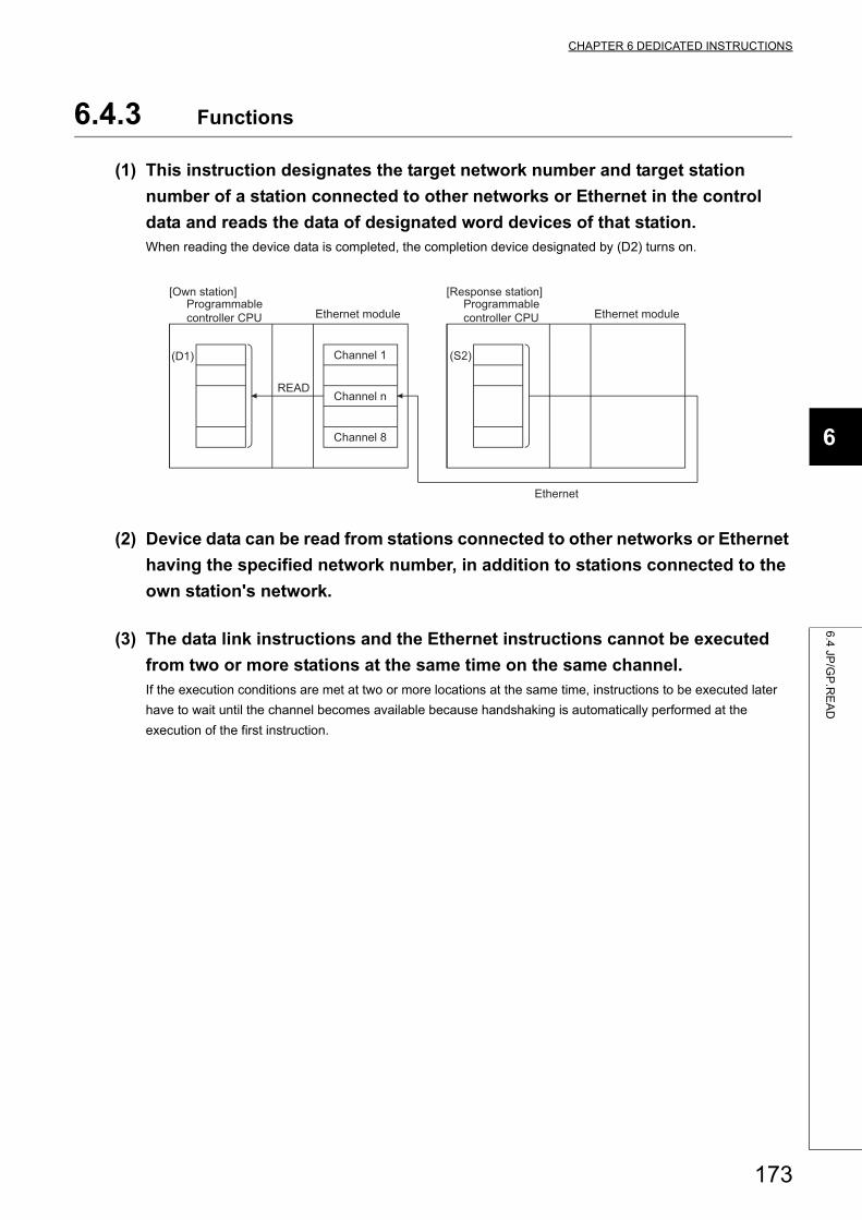
CHAPTER 6 DEDICATED INSTRUCTIONS
6
6.4
JP/G
P.R
EA
D
6.4.3 Functions
(1) This instruction designates the target network number and target station
number of a station connected to other networks or Ethernet in the control
data and reads the data of designated word devices of that station.When reading the device data is completed, the completion device designated by (D2) turns on.
(2) Device data can be read from stations connected to other networks or Ethernet
having the specified network number, in addition to stations connected to the
own station's network.
(3) The data link instructions and the Ethernet instructions cannot be executed
from two or more stations at the same time on the same channel.If the execution conditions are met at two or more locations at the same time, instructions to be executed later
have to wait until the channel becomes available because handshaking is automatically performed at the
execution of the first instruction.
READ
Ethernet
(D1) (S2)
Programmable controller CPU
Channel 1
Channel 8
Programmable controller CPU
[Own station]
Ethernet module
[Response station]
Ethernet module
Channel n
173
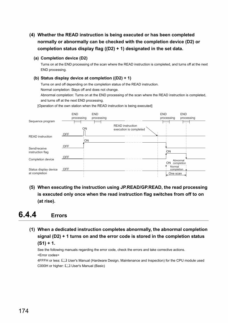
(4) Whether the READ instruction is being executed or has been completed
normally or abnormally can be checked with the completion device (D2) or
completion status display flag ((D2) + 1) designated in the set data.
(a) Completion device (D2)
Turns on at the END processing of the scan where the READ instruction is completed, and turns off at the next
END processing.
(b) Status display device at completion ((D2) + 1)
Turns on and off depending on the completion status of the READ instruction.
Normal completion: Stays off and does not change.
Abnormal completion: Turns on at the END processing of the scan where the READ instruction is completed,
and turns off at the next END processing.
[Operation of the own station when the READ instruction is being executed]
(5) When executing the instruction using JP.READ/GP.READ, the read processing
is executed only once when the read instruction flag switches from off to on
(at rise).
6.4.4 Errors
(1) When a dedicated instruction completes abnormally, the abnormal completion
signal (D2) + 1 turns on and the error code is stored in the completion status
(S1) + 1.See the following manuals regarding the error code, check the errors and take corrective actions.
<Error codes>
4FFFH or less: User's Manual (Hardware Design, Maintenance and Inspection) for the CPU module used
C000H or higher: User's Manual (Basic)
ON
OFF
OFF
ON
OFF
ON
OFF
ON
One scan
Normal completion
READ instruction execution is completed
END processing
END processing
END processing
END processing
Status display device at completion
Completion device
Send/receive instruction flag
READ instruction
Sequence program
Abnormal completion
174
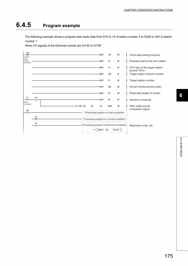
CHAPTER 6 DEDICATED INSTRUCTIONS
6
6.4
JP/G
P.R
EA
D
6.4.5 Program example
The following example shows a program that reads data from D10 to 14 of station number 4 to D200 to 204 of station
number 1.
When I/O signals of the Ethernet module are X/Y40 to X/Y5F
Clock data setting required
Channel used by the own station
Read error code, etc.
Arrival monitoring time (20s)
Target station number
Number of resends
MOV D1 D100
Control data setting command
Read command
CPU type of the target station (control CPU)Target station network number
Read data length (5 words)
X59: Initial normal completion signal
Processing program on abnormal completion
Processing program on read completion
Processing program on normal completion
175
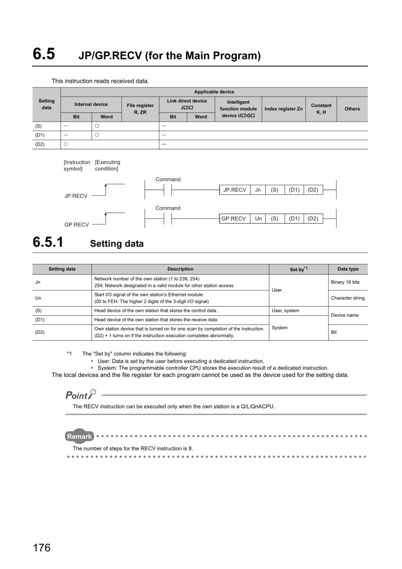
6.5 JP/GP.RECV (for the Main Program)
This instruction reads received data.
6.5.1 Setting data
*1 The "Set by" column indicates the following:• User: Data is set by the user before executing a dedicated instruction.• System: The programmable controller CPU stores the execution result of a dedicated instruction.
The local devices and the file register for each program cannot be used as the device used for the setting data.
The RECV instruction can be executed only when the own station is a Q/L/QnACPU.
Remark
The number of steps for the RECV instruction is 8.
Setting
data
Applicable device
Internal device File register
R, ZR
Link direct device
J\Intelligent
function module
device U\G
Index register ZnConstant
K, HOthers
Bit Word Bit Word
(S)
(D1)
(D2)
Setting data Description Set by*1 Data type
JnNetwork number of the own station (1 to 239, 254)
254: Network designated in a valid module for other station accessUser
Binary 16 bits
UnStart I/O signal of the own station's Ethernet module
(00 to FEH: The higher 2 digits of the 3-digit I/O signal)Character string
(S) Head device of the own station that stores the control data. User, systemDevice name
(D1) Head device of the own station that stores the receive data.
System(D2)
Own station device that is turned on for one scan by completion of the instruction.
(D2) + 1 turns on if the instruction execution completes abnormally.Bit
(S) (D2)(D1)
JP.RECV(S) (D2)(D1)
UnGP.RECV
GP.RECV
JnJP.RECV
[Executing condition]
[Instruction symbol]
Command
Command
176
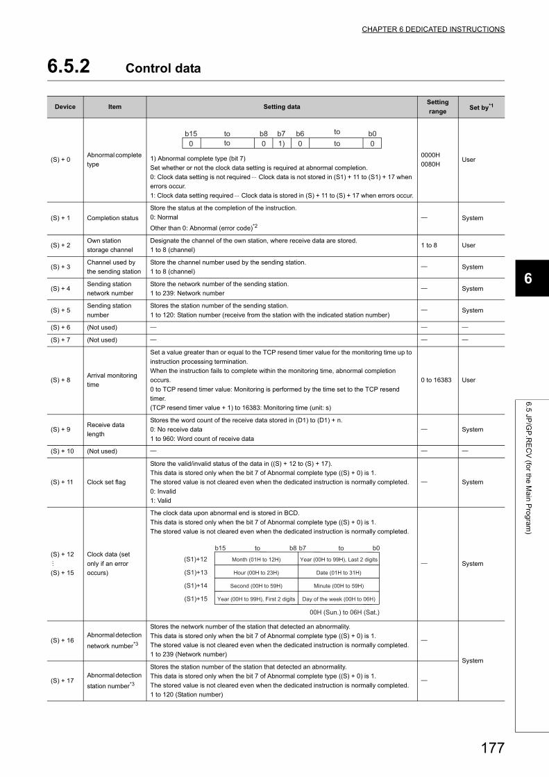
CHAPTER 6 DEDICATED INSTRUCTIONS
6
6.5
JP/G
P.R
EC
V (fo
r the
Ma
in P
rog
ram
)
6.5.2 Control data
Device Item Setting dataSetting
rangeSet by*1
(S) + 0Abnormal complete
type1) Abnormal complete type (bit 7)
Set whether or not the clock data setting is required at abnormal completion.
0: Clock data setting is not required Clock data is not stored in (S1) + 11 to (S1) + 17 when
errors occur.
1: Clock data setting required Clock data is stored in (S) + 11 to (S) + 17 when errors occur.
0000H
0080HUser
(S) + 1 Completion status
Store the status at the completion of the instruction.
0: Normal
Other than 0: Abnormal (error code)*2 System
(S) + 2Own station
storage channel
Designate the channel of the own station, where receive data are stored.
1 to 8 (channel)1 to 8 User
(S) + 3Channel used by
the sending station
Store the channel number used by the sending station.
1 to 8 (channel) System
(S) + 4Sending station
network number
Store the network number of the sending station.
1 to 239: Network number System
(S) + 5Sending station
number
Stores the station number of the sending station.
1 to 120: Station number (receive from the station with the indicated station number) System
(S) + 6 (Not used)
(S) + 7 (Not used)
(S) + 8Arrival monitoring
time
Set a value greater than or equal to the TCP resend timer value for the monitoring time up to
instruction processing termination.
When the instruction fails to complete within the monitoring time, abnormal completion
occurs.
0 to TCP resend timer value: Monitoring is performed by the time set to the TCP resend
timer.
(TCP resend timer value + 1) to 16383: Monitoring time (unit: s)
0 to 16383 User
(S) + 9Receive data
length
Stores the word count of the receive data stored in (D1) to (D1) + n.
0: No receive data
1 to 960: Word count of receive data
System
(S) + 10 (Not used)
(S) + 11 Clock set flag
Store the valid/invalid status of the data in ((S) + 12 to (S) + 17).
This data is stored only when the bit 7 of Abnormal complete type ((S) + 0) is 1.
The stored value is not cleared even when the dedicated instruction is normally completed.
0: Invalid
1: Valid
System
(S) + 12
(S) + 15
Clock data (set
only if an error
occurs)
The clock data upon abnormal end is stored in BCD.
This data is stored only when the bit 7 of Abnormal complete type ((S) + 0) is 1.
The stored value is not cleared even when the dedicated instruction is normally completed.
System
(S) + 16Abnormal detection
network number*3
Stores the network number of the station that detected an abnormality.
This data is stored only when the bit 7 of Abnormal complete type ((S) + 0) is 1.
The stored value is not cleared even when the dedicated instruction is normally completed.
1 to 239 (Network number)
System
(S) + 17Abnormal detection
station number*3
Stores the station number of the station that detected an abnormality.
This data is stored only when the bit 7 of Abnormal complete type ((S) + 0) is 1.
The stored value is not cleared even when the dedicated instruction is normally completed.
1 to 120 (Station number)
b80 0
b61) 0 0
b0b7b15totototo
(S1)+15
(S1)+14
(S1)+13
(S1)+12
b0b7b8b15
00H (Sun.) to 06H (Sat.)
Day of the week (00H to 06H)
Minute (00H to 59H)
Date (01H to 31H)
Year (00H to 99H), Last 2 digits
Year (00H to 99H), First 2 digits
Second (00H to 59H)
Hour (00H to 23H)
Month (01H to 12H)
toto
177
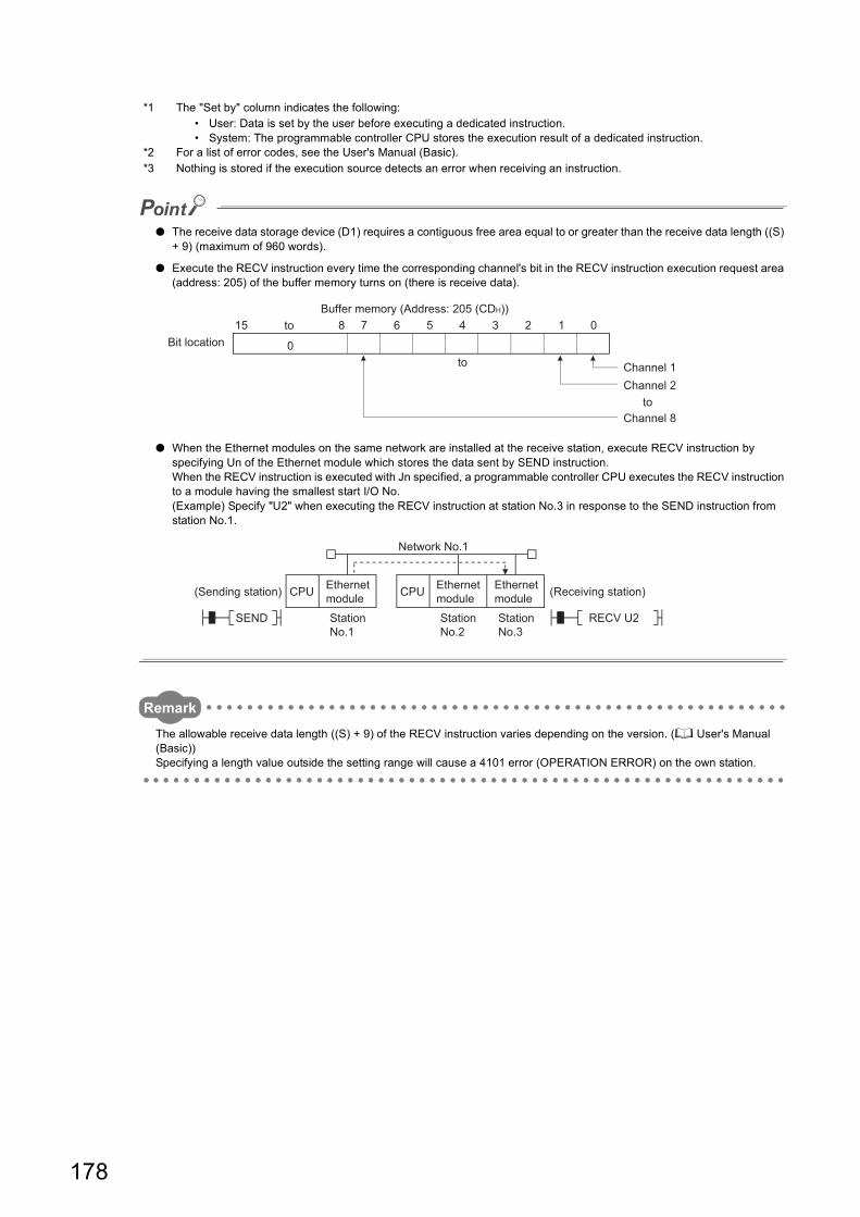
*1 The "Set by" column indicates the following:• User: Data is set by the user before executing a dedicated instruction.• System: The programmable controller CPU stores the execution result of a dedicated instruction.
*2 For a list of error codes, see the User's Manual (Basic).*3 Nothing is stored if the execution source detects an error when receiving an instruction.
● The receive data storage device (D1) requires a contiguous free area equal to or greater than the receive data length ((S) + 9) (maximum of 960 words).
● Execute the RECV instruction every time the corresponding channel's bit in the RECV instruction execution request area (address: 205) of the buffer memory turns on (there is receive data).
● When the Ethernet modules on the same network are installed at the receive station, execute RECV instruction by specifying Un of the Ethernet module which stores the data sent by SEND instruction.When the RECV instruction is executed with Jn specified, a programmable controller CPU executes the RECV instruction to a module having the smallest start I/O No.(Example) Specify "U2" when executing the RECV instruction at station No.3 in response to the SEND instruction from station No.1.
Remark
The allowable receive data length ((S) + 9) of the RECV instruction varies depending on the version. ( User's Manual (Basic))Specifying a length value outside the setting range will cause a 4101 error (OPERATION ERROR) on the own station.
0
815 7 6 5 4 3 2 1 0
Channel 8
Channel 2Channel 1to
to
toBit location
Buffer memory (Address: 205 (CDH))
RECV U2
CPUCPU
SEND
(Receiving station)
Station No.3
Station No.2
(Sending station)
Network No.1
Ethernet module
Ethernet module
Ethernet module
Station No.1
178
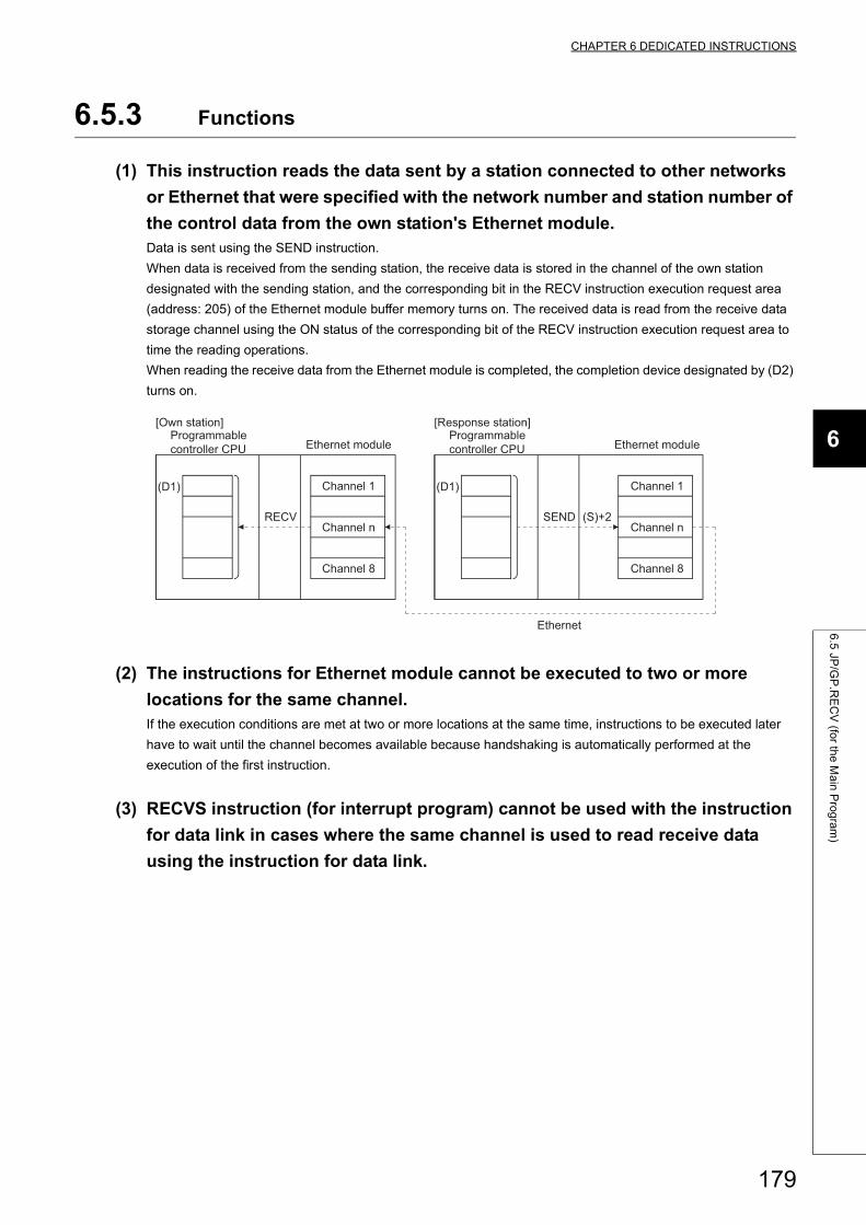
CHAPTER 6 DEDICATED INSTRUCTIONS
6
6.5
JP/G
P.R
EC
V (fo
r the
Ma
in P
rog
ram
)
6.5.3 Functions
(1) This instruction reads the data sent by a station connected to other networks
or Ethernet that were specified with the network number and station number of
the control data from the own station's Ethernet module.Data is sent using the SEND instruction.
When data is received from the sending station, the receive data is stored in the channel of the own station
designated with the sending station, and the corresponding bit in the RECV instruction execution request area
(address: 205) of the Ethernet module buffer memory turns on. The received data is read from the receive data
storage channel using the ON status of the corresponding bit of the RECV instruction execution request area to
time the reading operations.
When reading the receive data from the Ethernet module is completed, the completion device designated by (D2)
turns on.
(2) The instructions for Ethernet module cannot be executed to two or more
locations for the same channel.If the execution conditions are met at two or more locations at the same time, instructions to be executed later
have to wait until the channel becomes available because handshaking is automatically performed at the
execution of the first instruction.
(3) RECVS instruction (for interrupt program) cannot be used with the instruction
for data link in cases where the same channel is used to read receive data
using the instruction for data link.
SEND
(D1)
RECV
(D1)
(S)+2
Ethernet
Channel 1
Channel 8
Programmable controller CPU
Channel 1
Channel 8
Programmable controller CPU
[Own station] [Response station]
Ethernet module Ethernet module
Channel n Channel n
179
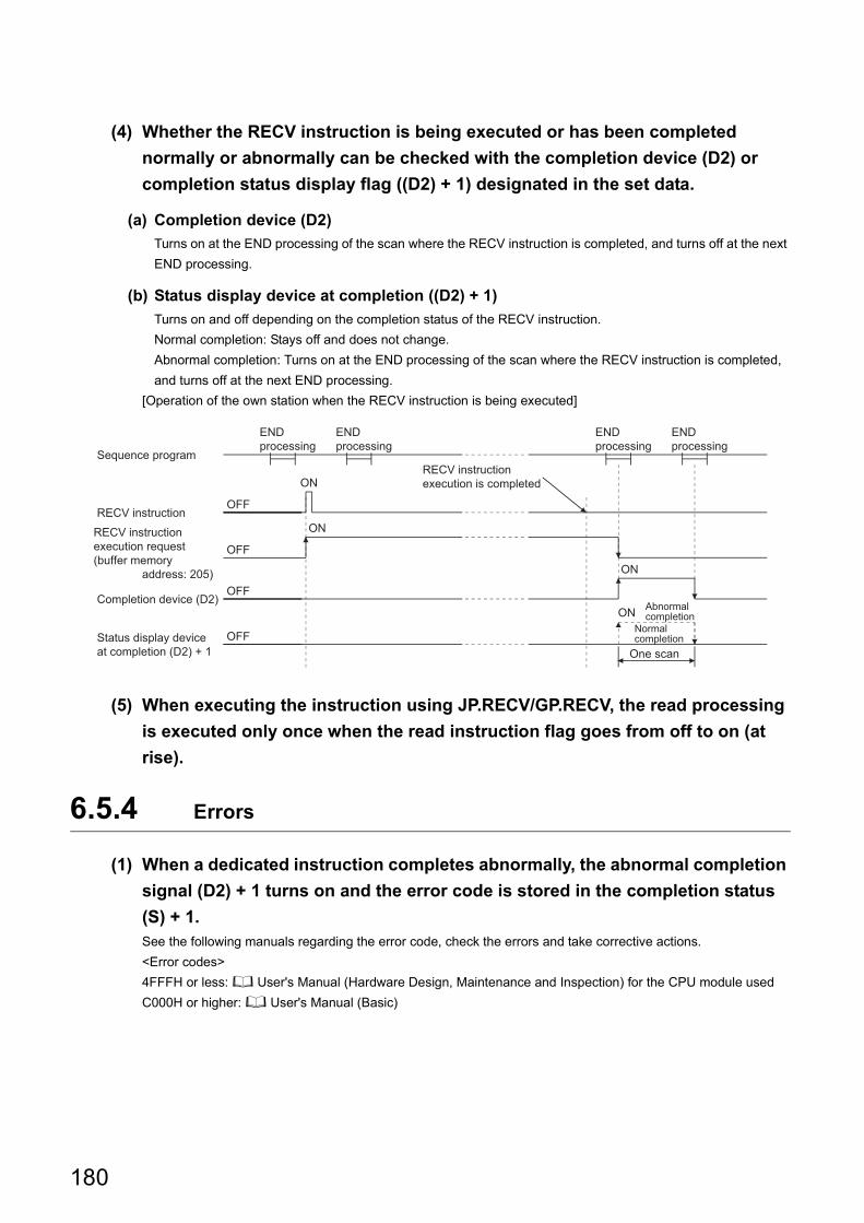
(4) Whether the RECV instruction is being executed or has been completed
normally or abnormally can be checked with the completion device (D2) or
completion status display flag ((D2) + 1) designated in the set data.
(a) Completion device (D2)
Turns on at the END processing of the scan where the RECV instruction is completed, and turns off at the next
END processing.
(b) Status display device at completion ((D2) + 1)
Turns on and off depending on the completion status of the RECV instruction.
Normal completion: Stays off and does not change.
Abnormal completion: Turns on at the END processing of the scan where the RECV instruction is completed,
and turns off at the next END processing.
[Operation of the own station when the RECV instruction is being executed]
(5) When executing the instruction using JP.RECV/GP.RECV, the read processing
is executed only once when the read instruction flag goes from off to on (at
rise).
6.5.4 Errors
(1) When a dedicated instruction completes abnormally, the abnormal completion
signal (D2) + 1 turns on and the error code is stored in the completion status
(S) + 1.See the following manuals regarding the error code, check the errors and take corrective actions.
<Error codes>
4FFFH or less: User's Manual (Hardware Design, Maintenance and Inspection) for the CPU module used
C000H or higher: User's Manual (Basic)
ON
OFF
OFF
ON
OFF
ON
OFF
ON
One scan
Abnormal completion
END processing
END processing
END processing
END processing
RECV instruction execution request (buffer memory address: 205)
RECV instruction
Normal completionStatus display device
at completion (D2) + 1
Completion device (D2)
RECV instruction execution is completed
Sequence program
180
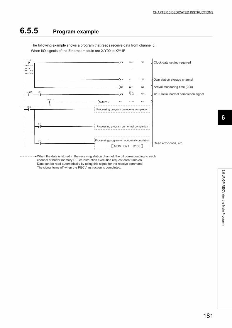
CHAPTER 6 DEDICATED INSTRUCTIONS
6
6.5
JP/G
P.R
EC
V (fo
r the
Ma
in P
rog
ram
)
6.5.5 Program example
The following example shows a program that reads receive data from channel 5.
When I/O signals of the Ethernet module are X/Y00 to X/Y1F
When the data is stored in the receiving station channel, the bit corresponding to each channel of buffer memory RECV instruction execution request area turns on. Data can be read automatically by using this signal for the receive command. The signal turns off when the RECV instruction is completed.
X19: Initial normal completion signal
Processing program on abnormal completion
Processing program on normal completion
Processing program on receive completion
Read error code, etc.
Arrival monitoring time (20s)
Own station storage channel
Clock data setting required
D100D21MOV
181
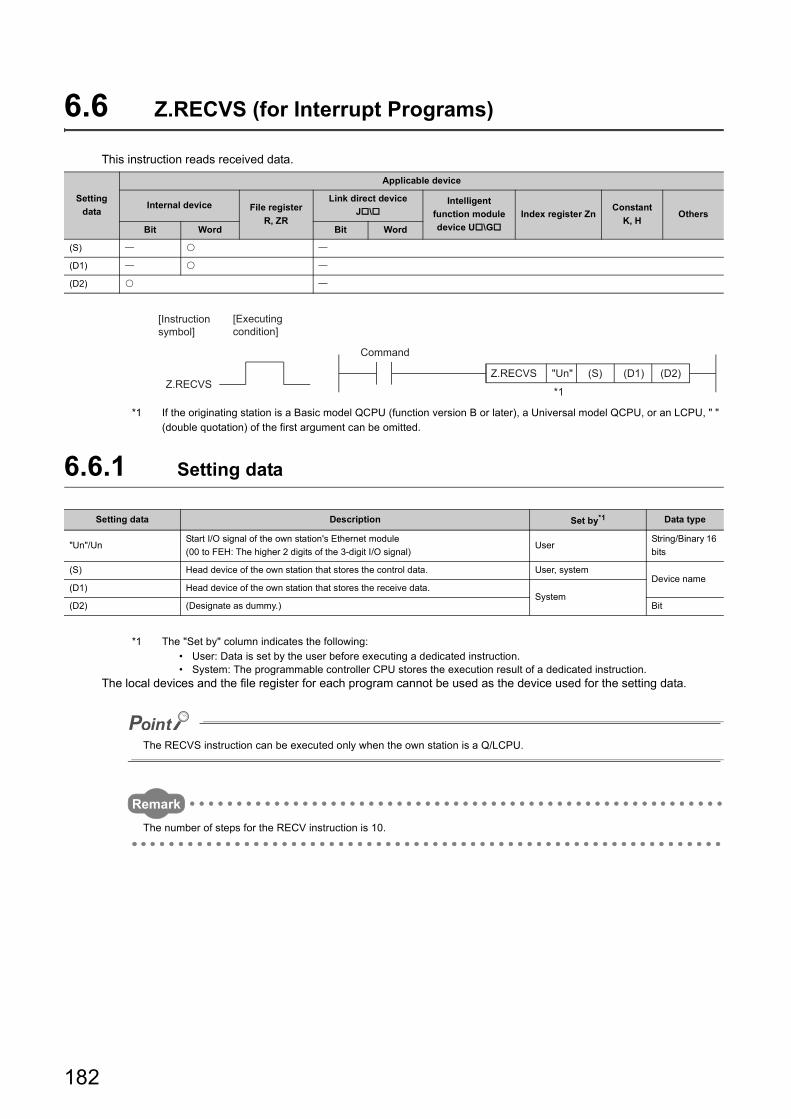
6.6 Z.RECVS (for Interrupt Programs)
This instruction reads received data.
*1 If the originating station is a Basic model QCPU (function version B or later), a Universal model QCPU, or an LCPU, " " (double quotation) of the first argument can be omitted.
6.6.1 Setting data
*1 The "Set by" column indicates the following:• User: Data is set by the user before executing a dedicated instruction.• System: The programmable controller CPU stores the execution result of a dedicated instruction.
The local devices and the file register for each program cannot be used as the device used for the setting data.
The RECVS instruction can be executed only when the own station is a Q/LCPU.
Remark
The number of steps for the RECV instruction is 10.
Setting
data
Applicable device
Internal device File register
R, ZR
Link direct device
J\Intelligent
function module
device U\G
Index register ZnConstant
K, HOthers
Bit Word Bit Word
(S)
(D1)
(D2)
Setting data Description Set by*1 Data type
"Un"/UnStart I/O signal of the own station's Ethernet module
(00 to FEH: The higher 2 digits of the 3-digit I/O signal)User
String/Binary 16
bits
(S) Head device of the own station that stores the control data. User, systemDevice name
(D1) Head device of the own station that stores the receive data.System
(D2) (Designate as dummy.) Bit
(S) (D2)"Un"Z.RECVS
(D1)Z.RECVS
[Executing condition]
[Instruction symbol]
*1
Command
182
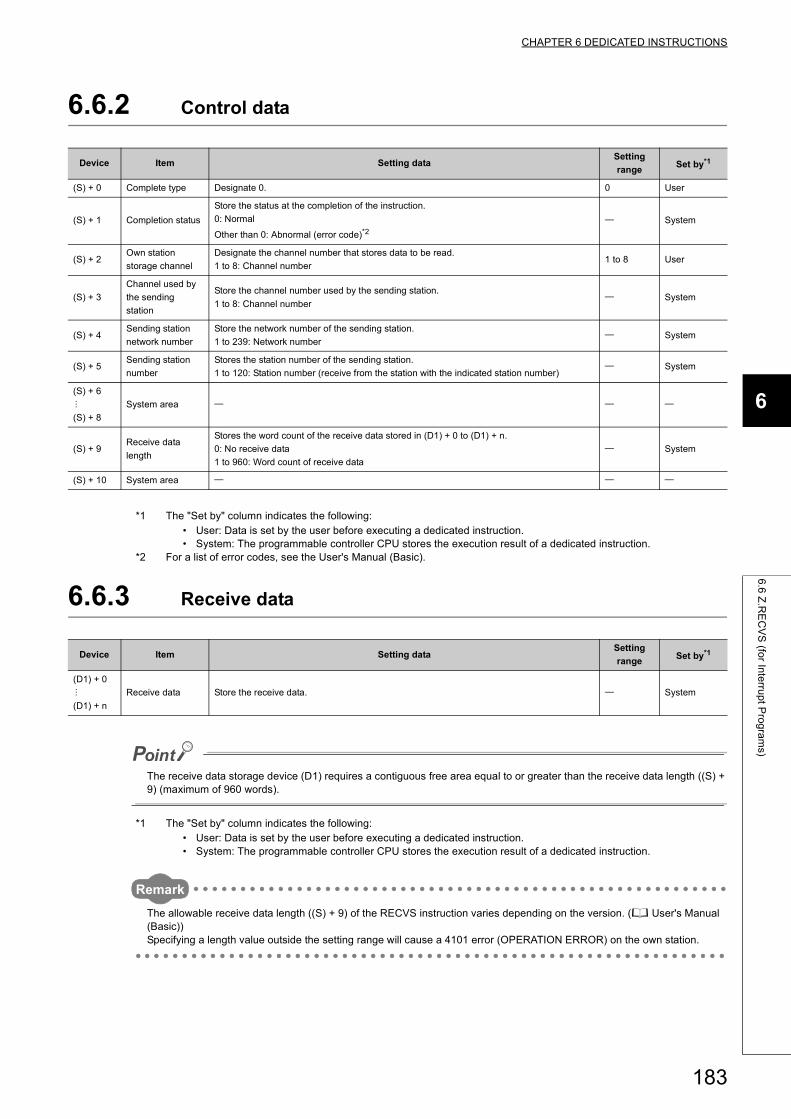
CHAPTER 6 DEDICATED INSTRUCTIONS
6
6.6
Z.R
EC
VS
(for In
terru
pt P
rog
ram
s)
6.6.2 Control data
*1 The "Set by" column indicates the following:• User: Data is set by the user before executing a dedicated instruction.• System: The programmable controller CPU stores the execution result of a dedicated instruction.
*2 For a list of error codes, see the User's Manual (Basic).
6.6.3 Receive data
The receive data storage device (D1) requires a contiguous free area equal to or greater than the receive data length ((S) + 9) (maximum of 960 words).
*1 The "Set by" column indicates the following:• User: Data is set by the user before executing a dedicated instruction.• System: The programmable controller CPU stores the execution result of a dedicated instruction.
Remark
The allowable receive data length ((S) + 9) of the RECVS instruction varies depending on the version. ( User's Manual (Basic))Specifying a length value outside the setting range will cause a 4101 error (OPERATION ERROR) on the own station.
Device Item Setting dataSetting
rangeSet by*1
(S) + 0 Complete type Designate 0. 0 User
(S) + 1 Completion status
Store the status at the completion of the instruction.
0: Normal
Other than 0: Abnormal (error code)*2 System
(S) + 2Own station
storage channel
Designate the channel number that stores data to be read.
1 to 8: Channel number1 to 8 User
(S) + 3
Channel used by
the sending
station
Store the channel number used by the sending station.
1 to 8: Channel number System
(S) + 4Sending station
network number
Store the network number of the sending station.
1 to 239: Network number System
(S) + 5Sending station
number
Stores the station number of the sending station.
1 to 120: Station number (receive from the station with the indicated station number) System
(S) + 6
(S) + 8
System area
(S) + 9Receive data
length
Stores the word count of the receive data stored in (D1) + 0 to (D1) + n.
0: No receive data
1 to 960: Word count of receive data
System
(S) + 10 System area
Device Item Setting dataSetting
rangeSet by*1
(D1) + 0
(D1) + n
Receive data Store the receive data. System
183
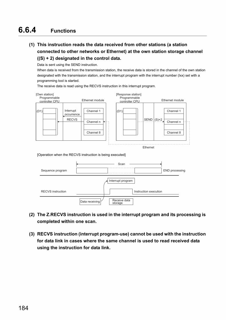
6.6.4 Functions
(1) This instruction reads the data received from other stations (a station
connected to other networks or Ethernet) at the own station storage channel
((S) + 2) designated in the control data.Data is sent using the SEND instruction.
When data is received from the transmission station, the receive data is stored in the channel of the own station
designated with the transmission station, and the interrupt program with the interrupt number (Ixx) set with a
programming tool is started.
The receive data is read using the RECVS instruction in this interrupt program.
[Operation when the RECVS instruction is being executed]
(2) The Z.RECVS instruction is used in the interrupt program and its processing is
completed within one scan.
(3) RECVS instruction (interrupt program-use) cannot be used with the instruction
for data link in cases where the same channel is used to read received data
using the instruction for data link.
SEND
(D1)
Ethernet
(D1)
(S)+2RECVS
Channel 1
Channel 8
Programmable controller CPU
Channel 1
Channel 8
Programmable controller CPU
[Own station] [Response station]
Ethernet module Ethernet module
Interrupt occurrence
Channel n Channel n
END processing
Interrupt program
RECVS instruction
Scan
Data receiving Receive data storage
Instruction execution
Sequence program
184
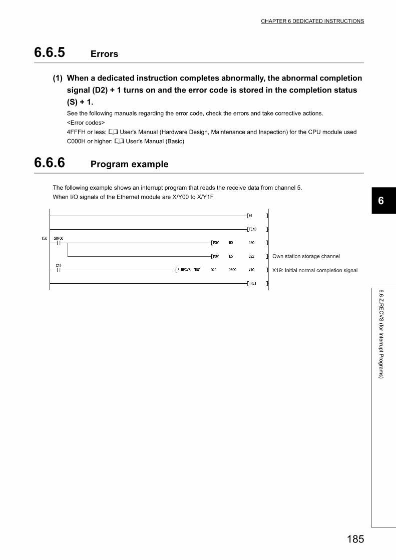
CHAPTER 6 DEDICATED INSTRUCTIONS
6
6.6
Z.R
EC
VS
(for In
terru
pt P
rog
ram
s)
6.6.5 Errors
(1) When a dedicated instruction completes abnormally, the abnormal completion
signal (D2) + 1 turns on and the error code is stored in the completion status
(S) + 1.See the following manuals regarding the error code, check the errors and take corrective actions.
<Error codes>
4FFFH or less: User's Manual (Hardware Design, Maintenance and Inspection) for the CPU module used
C000H or higher: User's Manual (Basic)
6.6.6 Program example
The following example shows an interrupt program that reads the receive data from channel 5.
When I/O signals of the Ethernet module are X/Y00 to X/Y1F
X19: Initial normal completion signal
Own station storage channel
185
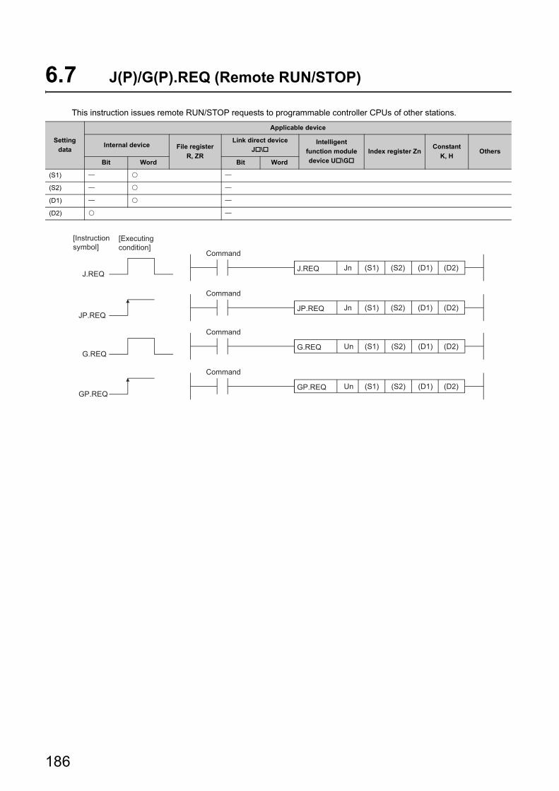
6.7 J(P)/G(P).REQ (Remote RUN/STOP)
This instruction issues remote RUN/STOP requests to programmable controller CPUs of other stations.
Setting
data
Applicable device
Internal device File register
R, ZR
Link direct device
J\Intelligent
function module
device U\G
Index register ZnConstant
K, HOthers
Bit Word Bit Word
(S1)
(S2)
(D1)
(D2)
(D2)(D1)(S2)(S1)Un
(D2)(D1)(S2)(S1)Jn
(D2)(D1)(S2)(S1)
GP.REQ
UnG.REQ
GP.REQ
G.REQ
(D2)
JP.REQ
(D1)(S2)(S1)JnJ.REQ
JP.REQ
J.REQ
[Executing condition]
[Instruction symbol]
Command
Command
Command
Command
186
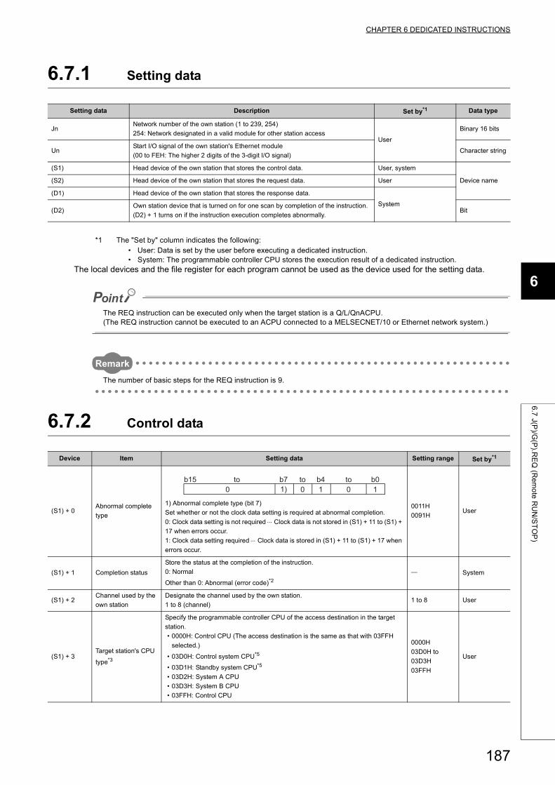
CHAPTER 6 DEDICATED INSTRUCTIONS
6
6.7
J(P)/G
(P).R
EQ
(Re
mo
te R
UN
/ST
OP
)
6.7.1 Setting data
*1 The "Set by" column indicates the following:• User: Data is set by the user before executing a dedicated instruction.• System: The programmable controller CPU stores the execution result of a dedicated instruction.
The local devices and the file register for each program cannot be used as the device used for the setting data.
The REQ instruction can be executed only when the target station is a Q/L/QnACPU.(The REQ instruction cannot be executed to an ACPU connected to a MELSECNET/10 or Ethernet network system.)
Remark
The number of basic steps for the REQ instruction is 9.
6.7.2 Control data
Setting data Description Set by*1 Data type
JnNetwork number of the own station (1 to 239, 254)
254: Network designated in a valid module for other station accessUser
Binary 16 bits
UnStart I/O signal of the own station's Ethernet module
(00 to FEH: The higher 2 digits of the 3-digit I/O signal)Character string
(S1) Head device of the own station that stores the control data. User, system
Device name(S2) Head device of the own station that stores the request data. User
(D1) Head device of the own station that stores the response data.
System(D2)
Own station device that is turned on for one scan by completion of the instruction.
(D2) + 1 turns on if the instruction execution completes abnormally.Bit
Device Item Setting data Setting range Set by*1
(S1) + 0Abnormal complete
type
1) Abnormal complete type (bit 7)
Set whether or not the clock data setting is required at abnormal completion.
0: Clock data setting is not required Clock data is not stored in (S1) + 11 to (S1) +
17 when errors occur.
1: Clock data setting required Clock data is stored in (S1) + 11 to (S1) + 17 when
errors occur.
0011H
0091HUser
(S1) + 1 Completion status
Store the status at the completion of the instruction.
0: Normal
Other than 0: Abnormal (error code)*2 System
(S1) + 2Channel used by the
own station
Designate the channel used by the own station.
1 to 8 (channel)1 to 8 User
(S1) + 3Target station's CPU
type*3
Specify the programmable controller CPU of the access destination in the target
station.
• 0000H: Control CPU (The access destination is the same as that with 03FFH
selected.)
• 03D0H: Control system CPU*5
• 03D1H: Standby system CPU*5
• 03D2H: System A CPU
• 03D3H: System B CPU
• 03FFH: Control CPU
0000H
03D0H to
03D3H
03FFH
User
b41) 0 1 0 10
b0b7b15 to toto
187
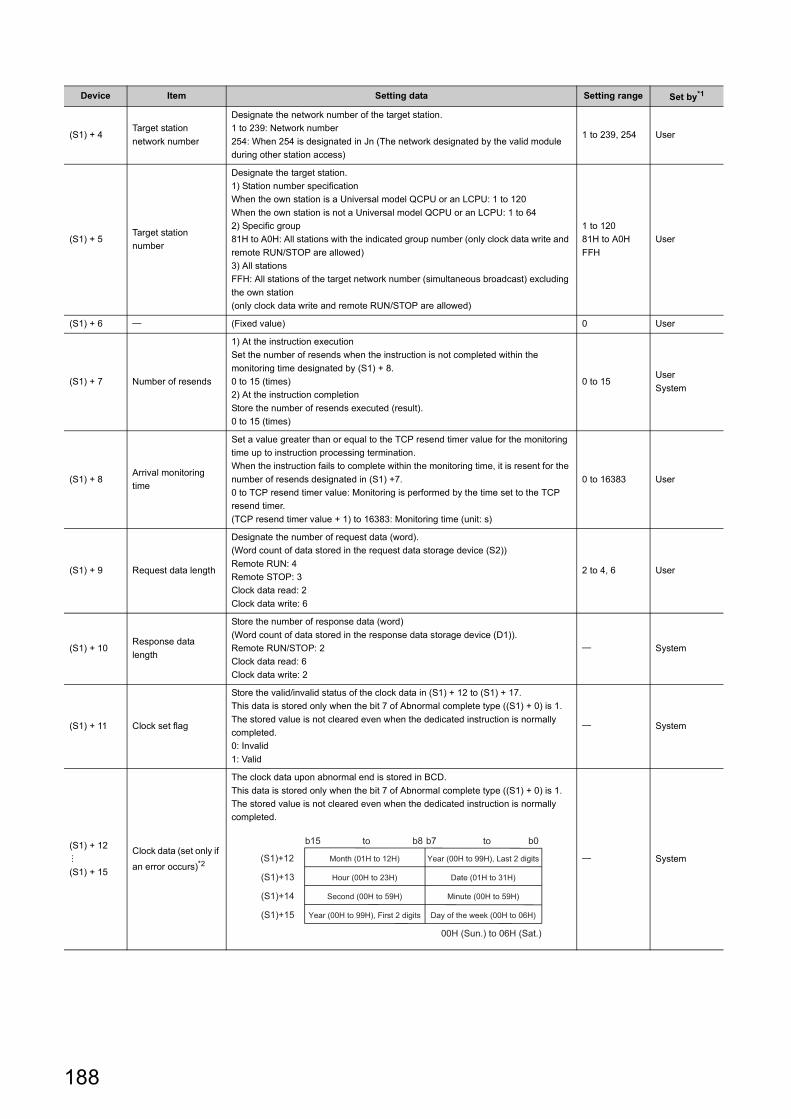
(S1) + 4Target station
network number
Designate the network number of the target station.
1 to 239: Network number
254: When 254 is designated in Jn (The network designated by the valid module
during other station access)
1 to 239, 254 User
(S1) + 5Target station
number
Designate the target station.
1) Station number specification
When the own station is a Universal model QCPU or an LCPU: 1 to 120
When the own station is not a Universal model QCPU or an LCPU: 1 to 64
2) Specific group
81H to A0H: All stations with the indicated group number (only clock data write and
remote RUN/STOP are allowed)
3) All stations
FFH: All stations of the target network number (simultaneous broadcast) excluding
the own station
(only clock data write and remote RUN/STOP are allowed)
1 to 120
81H to A0H
FFH
User
(S1) + 6 (Fixed value) 0 User
(S1) + 7 Number of resends
1) At the instruction execution
Set the number of resends when the instruction is not completed within the
monitoring time designated by (S1) + 8.
0 to 15 (times)
2) At the instruction completion
Store the number of resends executed (result).
0 to 15 (times)
0 to 15User
System
(S1) + 8Arrival monitoring
time
Set a value greater than or equal to the TCP resend timer value for the monitoring
time up to instruction processing termination.
When the instruction fails to complete within the monitoring time, it is resent for the
number of resends designated in (S1) +7.
0 to TCP resend timer value: Monitoring is performed by the time set to the TCP
resend timer.
(TCP resend timer value + 1) to 16383: Monitoring time (unit: s)
0 to 16383 User
(S1) + 9 Request data length
Designate the number of request data (word).
(Word count of data stored in the request data storage device (S2))
Remote RUN: 4
Remote STOP: 3
Clock data read: 2
Clock data write: 6
2 to 4, 6 User
(S1) + 10Response data
length
Store the number of response data (word)
(Word count of data stored in the response data storage device (D1)).
Remote RUN/STOP: 2
Clock data read: 6
Clock data write: 2
System
(S1) + 11 Clock set flag
Store the valid/invalid status of the clock data in (S1) + 12 to (S1) + 17.
This data is stored only when the bit 7 of Abnormal complete type ((S1) + 0) is 1.
The stored value is not cleared even when the dedicated instruction is normally
completed.
0: Invalid
1: Valid
System
(S1) + 12
(S1) + 15
Clock data (set only if
an error occurs)*2
The clock data upon abnormal end is stored in BCD.
This data is stored only when the bit 7 of Abnormal complete type ((S1) + 0) is 1.
The stored value is not cleared even when the dedicated instruction is normally
completed.
System
Device Item Setting data Setting range Set by*1
(S1)+15
(S1)+14
(S1)+13
(S1)+12
b0b7b8b15
00H (Sun.) to 06H (Sat.)
Day of the week (00H to 06H)
Minute (00H to 59H)
Date (01H to 31H)
Year (00H to 99H), Last 2 digits
Year (00H to 99H), First 2 digits
Second (00H to 59H)
Hour (00H to 23H)
Month (01H to 12H)
toto
188
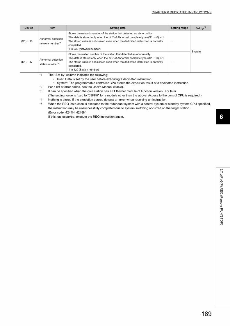
CHAPTER 6 DEDICATED INSTRUCTIONS
6
6.7
J(P)/G
(P).R
EQ
(Re
mo
te R
UN
/ST
OP
)
*1 The "Set by" column indicates the following:• User: Data is set by the user before executing a dedicated instruction.• System: The programmable controller CPU stores the execution result of a dedicated instruction.
*2 For a list of error codes, see the User's Manual (Basic).*3 It can be specified when the own station has an Ethernet module of function version D or later.
(The setting value is fixed to "03FFH" for a module other than the above. Access to the control CPU is required.)*4 Nothing is stored if the execution source detects an error when receiving an instruction.*5 When the REQ instruction is executed to the redundant system with a control system or standby system CPU specified,
the instruction may be unsuccessfully completed due to system switching occurred on the target station.(Error code: 4244H, 4248H)If this has occurred, execute the REQ instruction again.
(S1) + 16Abnormal detection
network number*4
Stores the network number of the station that detected an abnormality.
This data is stored only when the bit 7 of Abnormal complete type ((S1) + 0) is 1.
The stored value is not cleared even when the dedicated instruction is normally
completed.
1 to 239 (Network number)
System
(S1) + 17Abnormal detection
station number*4
Stores the station number of the station that detected an abnormality.
This data is stored only when the bit 7 of Abnormal complete type ((S1) + 0) is 1.
The stored value is not cleared even when the dedicated instruction is normally
completed.
1 to 120 (Station number)
Device Item Setting data Setting range Set by*1
189
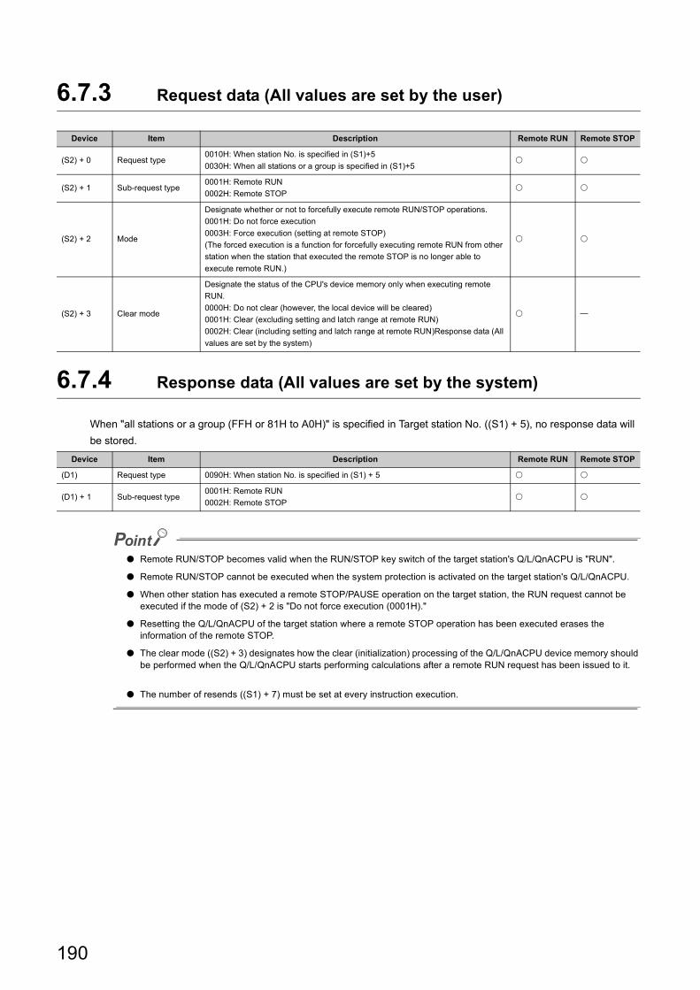
6.7.3 Request data (All values are set by the user)
6.7.4 Response data (All values are set by the system)
When "all stations or a group (FFH or 81H to A0H)" is specified in Target station No. ((S1) + 5), no response data will
be stored.
● Remote RUN/STOP becomes valid when the RUN/STOP key switch of the target station's Q/L/QnACPU is "RUN".
● Remote RUN/STOP cannot be executed when the system protection is activated on the target station's Q/L/QnACPU.
● When other station has executed a remote STOP/PAUSE operation on the target station, the RUN request cannot be executed if the mode of (S2) + 2 is "Do not force execution (0001H)."
● Resetting the Q/L/QnACPU of the target station where a remote STOP operation has been executed erases the information of the remote STOP.
● The clear mode ((S2) + 3) designates how the clear (initialization) processing of the Q/L/QnACPU device memory should be performed when the Q/L/QnACPU starts performing calculations after a remote RUN request has been issued to it.
● The number of resends ((S1) + 7) must be set at every instruction execution.
Device Item Description Remote RUN Remote STOP
(S2) + 0 Request type0010H: When station No. is specified in (S1)+5
0030H: When all stations or a group is specified in (S1)+5
(S2) + 1 Sub-request type0001H: Remote RUN
0002H: Remote STOP
(S2) + 2 Mode
Designate whether or not to forcefully execute remote RUN/STOP operations.
0001H: Do not force execution
0003H: Force execution (setting at remote STOP)
(The forced execution is a function for forcefully executing remote RUN from other
station when the station that executed the remote STOP is no longer able to
execute remote RUN.)
(S2) + 3 Clear mode
Designate the status of the CPU's device memory only when executing remote
RUN.
0000H: Do not clear (however, the local device will be cleared)
0001H: Clear (excluding setting and latch range at remote RUN)
0002H: Clear (including setting and latch range at remote RUN)Response data (All
values are set by the system)
Device Item Description Remote RUN Remote STOP
(D1) Request type 0090H: When station No. is specified in (S1) + 5
(D1) + 1 Sub-request type0001H: Remote RUN
0002H: Remote STOP
190
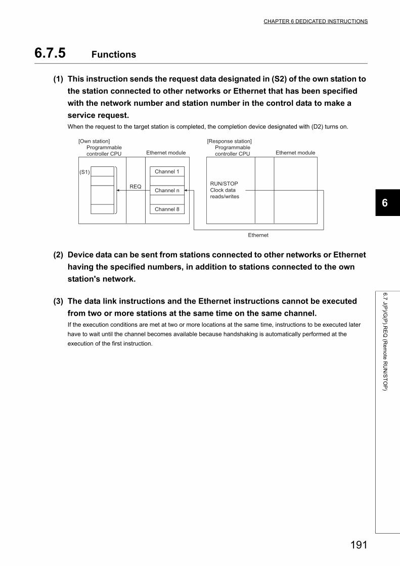
CHAPTER 6 DEDICATED INSTRUCTIONS
6
6.7
J(P)/G
(P).R
EQ
(Re
mo
te R
UN
/ST
OP
)
6.7.5 Functions
(1) This instruction sends the request data designated in (S2) of the own station to
the station connected to other networks or Ethernet that has been specified
with the network number and station number in the control data to make a
service request.When the request to the target station is completed, the completion device designated with (D2) turns on.
(2) Device data can be sent from stations connected to other networks or Ethernet
having the specified numbers, in addition to stations connected to the own
station's network.
(3) The data link instructions and the Ethernet instructions cannot be executed
from two or more stations at the same time on the same channel.If the execution conditions are met at two or more locations at the same time, instructions to be executed later
have to wait until the channel becomes available because handshaking is automatically performed at the
execution of the first instruction.
REQ
Ethernet
(S1)
Programmable controller CPU
Channel 1
Channel 8
Programmable controller CPU
[Own station]
Ethernet module
[Response station]
Ethernet module
Channel nRUN/STOPClock data reads/writes
191
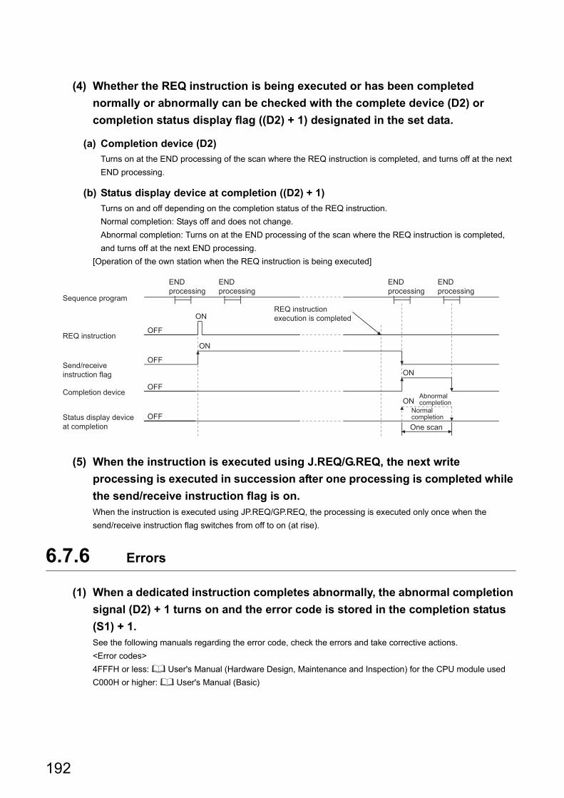
(4) Whether the REQ instruction is being executed or has been completed
normally or abnormally can be checked with the complete device (D2) or
completion status display flag ((D2) + 1) designated in the set data.
(a) Completion device (D2)
Turns on at the END processing of the scan where the REQ instruction is completed, and turns off at the next
END processing.
(b) Status display device at completion ((D2) + 1)
Turns on and off depending on the completion status of the REQ instruction.
Normal completion: Stays off and does not change.
Abnormal completion: Turns on at the END processing of the scan where the REQ instruction is completed,
and turns off at the next END processing.
[Operation of the own station when the REQ instruction is being executed]
(5) When the instruction is executed using J.REQ/G.REQ, the next write
processing is executed in succession after one processing is completed while
the send/receive instruction flag is on.When the instruction is executed using JP.REQ/GP.REQ, the processing is executed only once when the
send/receive instruction flag switches from off to on (at rise).
6.7.6 Errors
(1) When a dedicated instruction completes abnormally, the abnormal completion
signal (D2) + 1 turns on and the error code is stored in the completion status
(S1) + 1.See the following manuals regarding the error code, check the errors and take corrective actions.
<Error codes>
4FFFH or less: User's Manual (Hardware Design, Maintenance and Inspection) for the CPU module used
C000H or higher: User's Manual (Basic)
ON
OFF
OFF
ON
OFF
ON
OFF
ONAbnormal completion
END processing
END processing
END processing
END processing
Status display device at completion One scan
Normal completion
Completion device
Send/receive instruction flag
REQ instruction execution is completed
REQ instruction
Sequence program
192
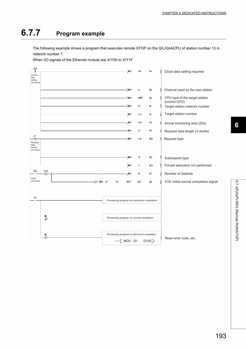
CHAPTER 6 DEDICATED INSTRUCTIONS
6
6.7
J(P)/G
(P).R
EQ
(Re
mo
te R
UN
/ST
OP
)
6.7.7 Program example
The following example shows a program that executes remote STOP on the Q/L/QnACPU of station number 13 in
network number 7.
When I/O signals of the Ethernet module are X/Y00 to X/Y1F
Clock data setting required
Channel used by the own station
Request data length (3 words)
Read error code, etc.
Target station number
Number of resends
Request type
Subrequest type
Target station network number
Processing program on instruction completion
Processing program on normal completion
Processing program on abnormal completion
MOV D1 D100
Arrival monitoring time (20s)
Control data setting command
Request data setting command
Write command
CPU type of the target station (control CPU)
Forced execution not performed
X19: Initial normal completion signal
193
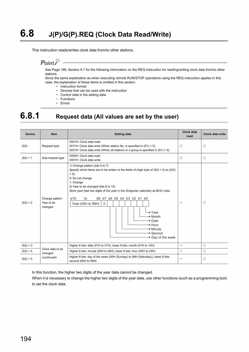
6.8 J(P)/G(P).REQ (Clock Data Read/Write)
This instruction reads/writes clock data from/to other stations.
See Page 186, Section 6.7 for the following information on the REQ instruction for reading/writing clock data from/to other stations.Since the same explanation as when executing remote RUN/STOP operations using the REQ instruction applies in this case, the explanation of these items is omitted in this section.
• Instruction format• Devices that can be used with the instruction• Control data in the setting data• Functions• Errors
6.8.1 Request data (All values are set by the user)
In this function, the higher two digits of the year data cannot be changed.
When it is necessary to change the higher two digits of the year data, use other functions (such as a programming tool)
to set the clock data.
Device Item Setting dataClock data
readClock data write
(S2) Request type
0001H: Clock data read
0011H: Clock data write (When station No. is specified in (S1) + 5)
0031H: Clock data write (When all stations or a group is specified in (S1) + 5)
(S2) + 1 Sub-request type0002H: Clock data read
0001H: Clock data write
(S2) + 2
Change pattern
Year to be
changed
1) Change pattern (bits 0 to 7)
Specify which items are to be written to the fields of (high byte of (S2) + 2) to ((S2)
+ 5).
0: Do not change
1: Change
2) Year to be changed (bits 8 to 15)
Store year (last two digits of the year in the Gregorian calendar) as BCD code.
(S2) + 3Clock data to be
changed
(continued)
Higher 8 bits: date (01H to 31H), lower 8 bits: month (01H to 12H)
(S2) + 4 Higher 8 bits: minute (00H to 59H), lower 8 bits: hour (00H to 23H)
(S2) + 5Higher 8 bits: day of the week (00H (Sunday) to 06H (Saturday)), lower 8 bits:
second (00H to 59H)
b8 b0b1b2b3b4b5b6b7b150Year (00H to 99H)
Day of the weekSecondMinuteHourDateMonthYear
to
194
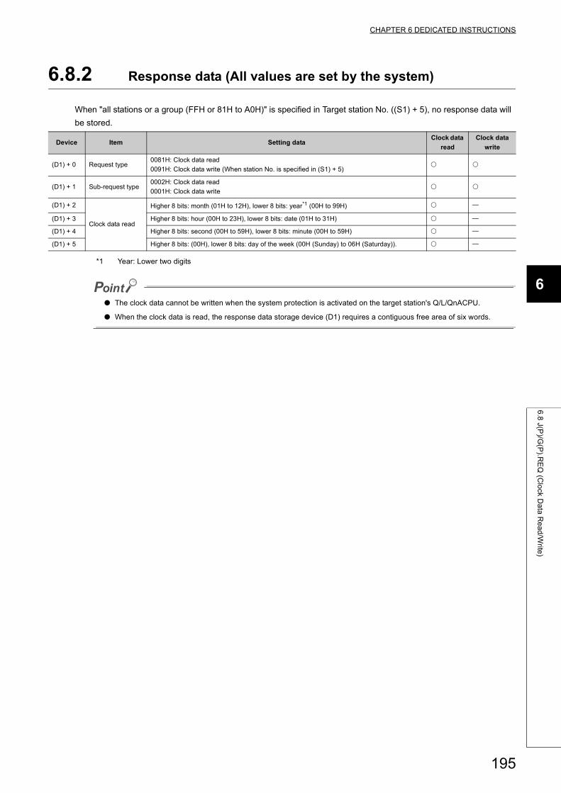
CHAPTER 6 DEDICATED INSTRUCTIONS
6
6.8
J(P)/G
(P).R
EQ
(Clo
ck Da
ta R
ea
d/W
rite)
6.8.2 Response data (All values are set by the system)
When "all stations or a group (FFH or 81H to A0H)" is specified in Target station No. ((S1) + 5), no response data will
be stored.
*1 Year: Lower two digits
● The clock data cannot be written when the system protection is activated on the target station's Q/L/QnACPU.
● When the clock data is read, the response data storage device (D1) requires a contiguous free area of six words.
Device Item Setting dataClock data
read
Clock data
write
(D1) + 0 Request type0081H: Clock data read
0091H: Clock data write (When station No. is specified in (S1) + 5)
(D1) + 1 Sub-request type0002H: Clock data read
0001H: Clock data write
(D1) + 2
Clock data read
Higher 8 bits: month (01H to 12H), lower 8 bits: year*1 (00H to 99H)
(D1) + 3 Higher 8 bits: hour (00H to 23H), lower 8 bits: date (01H to 31H)
(D1) + 4 Higher 8 bits: second (00H to 59H), lower 8 bits: minute (00H to 59H)
(D1) + 5 Higher 8 bits: (00H), lower 8 bits: day of the week (00H (Sunday) to 06H (Saturday)).
195
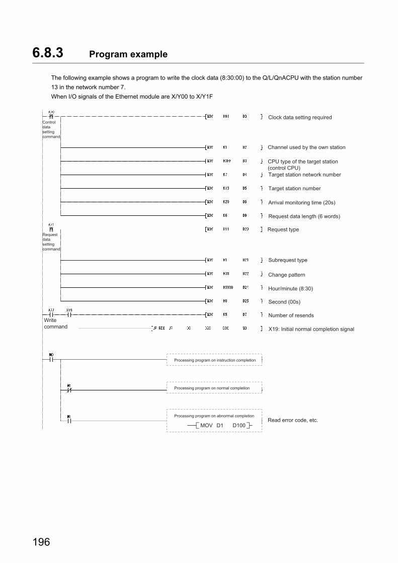
6.8.3 Program example
The following example shows a program to write the clock data (8:30:00) to the Q/L/QnACPU with the station number
13 in the network number 7.
When I/O signals of the Ethernet module are X/Y00 to X/Y1F
Clock data setting required
Channel used by the own station
Request data length (6 words)
Read error code, etc.
Arrival monitoring time (20s)
Target station number
Request type
Subrequest type
Target station network number
Processing program on instruction completion
Processing program on normal completion
Processing program on abnormal completion
MOV D1 D100
Change pattern
Control data setting command
Request data setting command
Write command
CPU type of the target station (control CPU)
Hour/minute (8:30)
Second (00s)
Number of resends
X19: Initial normal completion signal
196
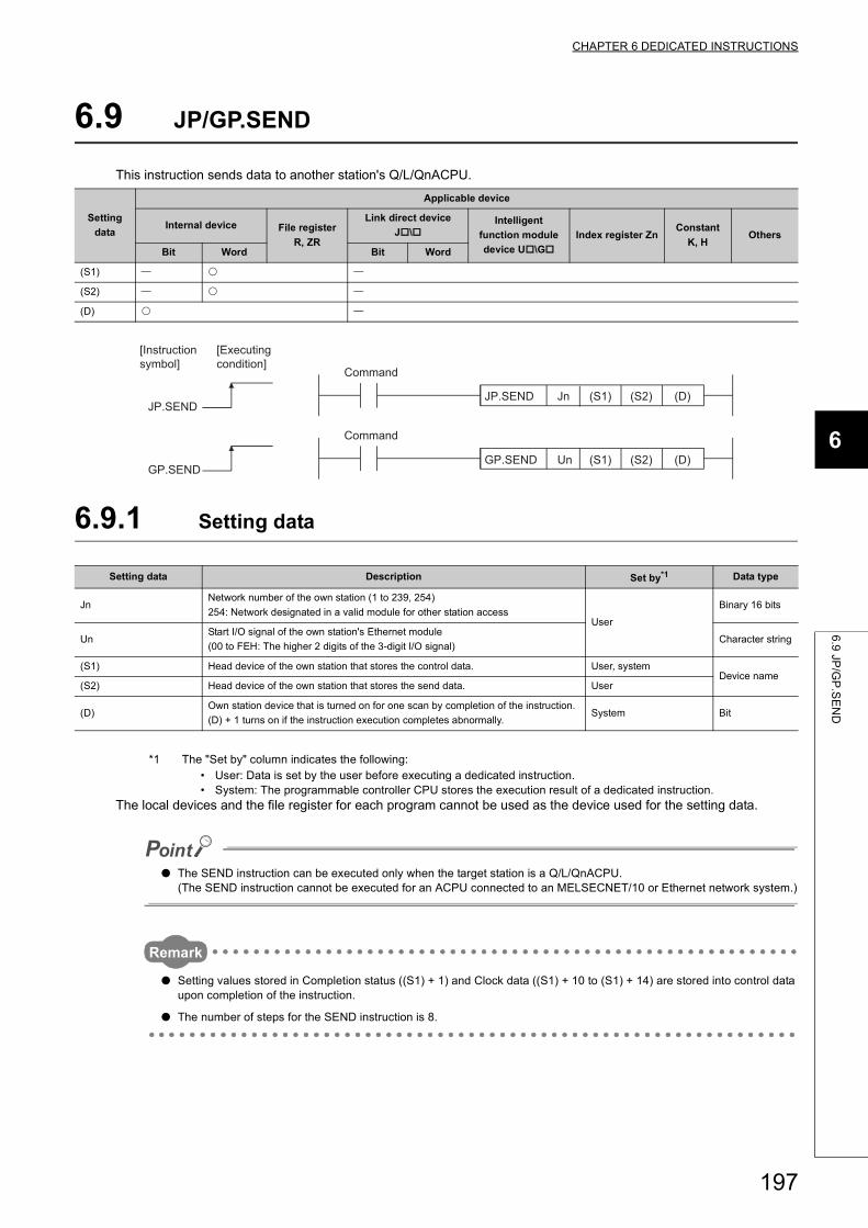
CHAPTER 6 DEDICATED INSTRUCTIONS
6
6.9
JP/G
P.S
EN
D
6.9 JP/GP.SEND
This instruction sends data to another station's Q/L/QnACPU.
6.9.1 Setting data
*1 The "Set by" column indicates the following:• User: Data is set by the user before executing a dedicated instruction.• System: The programmable controller CPU stores the execution result of a dedicated instruction.
The local devices and the file register for each program cannot be used as the device used for the setting data.
● The SEND instruction can be executed only when the target station is a Q/L/QnACPU.(The SEND instruction cannot be executed for an ACPU connected to an MELSECNET/10 or Ethernet network system.)
Remark
● Setting values stored in Completion status ((S1) + 1) and Clock data ((S1) + 10 to (S1) + 14) are stored into control data upon completion of the instruction.
● The number of steps for the SEND instruction is 8.
Setting
data
Applicable device
Internal device File register
R, ZR
Link direct device
J\Intelligent
function module
device U\G
Index register ZnConstant
K, HOthers
Bit Word Bit Word
(S1)
(S2)
(D)
Setting data Description Set by*1 Data type
JnNetwork number of the own station (1 to 239, 254)
254: Network designated in a valid module for other station accessUser
Binary 16 bits
UnStart I/O signal of the own station's Ethernet module
(00 to FEH: The higher 2 digits of the 3-digit I/O signal)Character string
(S1) Head device of the own station that stores the control data. User, systemDevice name
(S2) Head device of the own station that stores the send data. User
(D)Own station device that is turned on for one scan by completion of the instruction.
(D) + 1 turns on if the instruction execution completes abnormally.System Bit
(D)(S2)(S1)GP.SEND
UnGP.SEND
JP.SEND(D)(S2)(S1)JnJP.SEND
[Executing condition]
[Instruction symbol]
Command
Command
197
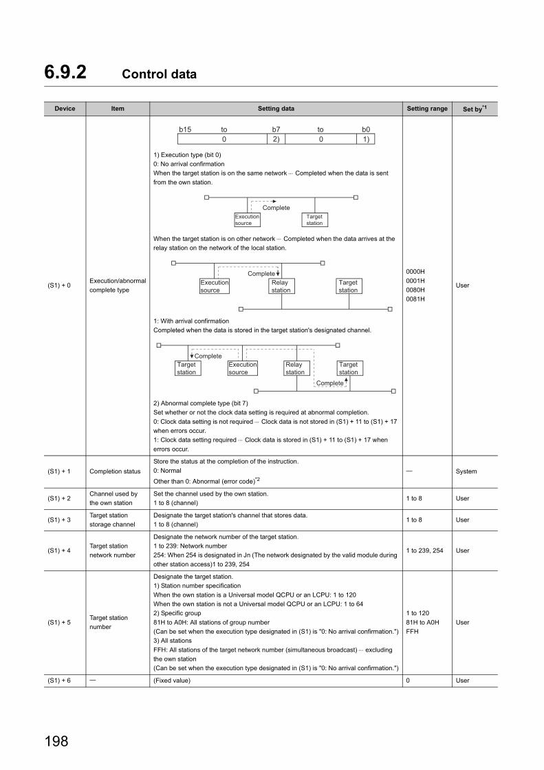
6.9.2 Control data
Device Item Setting data Setting range Set by*1
(S1) + 0Execution/abnormal
complete type
1) Execution type (bit 0)
0: No arrival confirmation
When the target station is on the same network Completed when the data is sent
from the own station.
When the target station is on other network Completed when the data arrives at the
relay station on the network of the local station.
1: With arrival confirmation
Completed when the data is stored in the target station's designated channel.
2) Abnormal complete type (bit 7)
Set whether or not the clock data setting is required at abnormal completion.
0: Clock data setting is not required Clock data is not stored in (S1) + 11 to (S1) + 17
when errors occur.
1: Clock data setting required Clock data is stored in (S1) + 11 to (S1) + 17 when
errors occur.
0000H
0001H
0080H
0081H
User
(S1) + 1 Completion status
Store the status at the completion of the instruction.
0: Normal
Other than 0: Abnormal (error code)*2 System
(S1) + 2Channel used by
the own station
Set the channel used by the own station.
1 to 8 (channel)1 to 8 User
(S1) + 3Target station
storage channel
Designate the target station's channel that stores data.
1 to 8 (channel)1 to 8 User
(S1) + 4Target station
network number
Designate the network number of the target station.
1 to 239: Network number
254: When 254 is designated in Jn (The network designated by the valid module during
other station access)1 to 239, 254
1 to 239, 254 User
(S1) + 5Target station
number
Designate the target station.
1) Station number specification
When the own station is a Universal model QCPU or an LCPU: 1 to 120
When the own station is not a Universal model QCPU or an LCPU: 1 to 64
2) Specific group
81H to A0H: All stations of group number
(Can be set when the execution type designated in (S1) is "0: No arrival confirmation.")
3) All stations
FFH: All stations of the target network number (simultaneous broadcast) excluding
the own station
(Can be set when the execution type designated in (S1) is "0: No arrival confirmation.")
1 to 120
81H to A0H
FFH
User
(S1) + 6 (Fixed value) 0 User
02) 1)0b0b7b15 toto
CompleteTarget station
Execution source
CompleteTarget station
Relay station
Execution source
Complete
CompleteTarget station
Target station
Relay station
Execution source
198
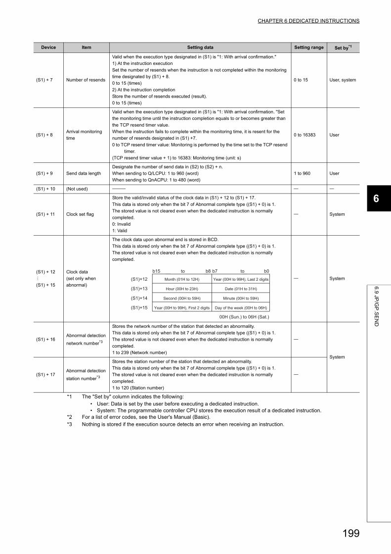
CHAPTER 6 DEDICATED INSTRUCTIONS
6
6.9
JP/G
P.S
EN
D
*1 The "Set by" column indicates the following:• User: Data is set by the user before executing a dedicated instruction.• System: The programmable controller CPU stores the execution result of a dedicated instruction.
*2 For a list of error codes, see the User's Manual (Basic).*3 Nothing is stored if the execution source detects an error when receiving an instruction.
(S1) + 7 Number of resends
Valid when the execution type designated in (S1) is "1: With arrival confirmation."
1) At the instruction execution
Set the number of resends when the instruction is not completed within the monitoring
time designated by (S1) + 8.
0 to 15 (times)
2) At the instruction completion
Store the number of resends executed (result).
0 to 15 (times)
0 to 15 User, system
(S1) + 8Arrival monitoring
time
Valid when the execution type designated in (S1) is "1: With arrival confirmation. "Set
the monitoring time until the instruction completion equals to or becomes greater than
the TCP resend timer value.
When the instruction fails to complete within the monitoring time, it is resent for the
number of resends designated in (S1) +7.
0 to TCP resend timer value: Monitoring is performed by the time set to the TCP resend
timer.
(TCP resend timer value + 1) to 16383: Monitoring time (unit: s)
0 to 16383 User
(S1) + 9 Send data length
Designate the number of send data in (S2) to (S2) + n.
When sending to Q/LCPU: 1 to 960 (word)
When sending to QnACPU: 1 to 480 (word)
1 to 960 User
(S1) + 10 (Not used)
(S1) + 11 Clock set flag
Store the valid/invalid status of the clock data in (S1) + 12 to (S1) + 17.
This data is stored only when the bit 7 of Abnormal complete type ((S1) + 0) is 1.
The stored value is not cleared even when the dedicated instruction is normally
completed.
0: Invalid
1: Valid
System
(S1) + 12
(S1) + 15
Clock data
(set only when
abnormal)
The clock data upon abnormal end is stored in BCD.
This data is stored only when the bit 7 of Abnormal complete type ((S1) + 0) is 1.
The stored value is not cleared even when the dedicated instruction is normally
completed.
System
(S1) + 16Abnormal detection
network number*3
Stores the network number of the station that detected an abnormality.
This data is stored only when the bit 7 of Abnormal complete type ((S1) + 0) is 1.
The stored value is not cleared even when the dedicated instruction is normally
completed.
1 to 239 (Network number)
System
(S1) + 17Abnormal detection
station number*3
Stores the station number of the station that detected an abnormality.
This data is stored only when the bit 7 of Abnormal complete type ((S1) + 0) is 1.
The stored value is not cleared even when the dedicated instruction is normally
completed.
1 to 120 (Station number)
Device Item Setting data Setting range Set by*1
(S1)+15
(S1)+14
(S1)+13
(S1)+12
b0b7b8b15
00H (Sun.) to 06H (Sat.)
Day of the week (00H to 06H)
Minute (00H to 59H)
Date (01H to 31H)
Year (00H to 99H), Last 2 digits
Year (00H to 99H), First 2 digits
Second (00H to 59H)
Hour (00H to 23H)
Month (01H to 12H)
toto
199
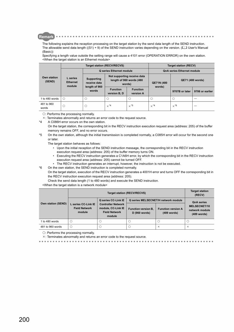
Remark
The following explains the reception processing on the target station by the send data length of the SEND instruction.The allowable send data length ((S1) + 9) of the SEND instruction varies depending on the version. ( User's Manual (Basic))Specifying a length value outside the setting range will cause a 4101 error (OPERATION ERROR) on the own station.<When the target station is an Ethernet module>
: Performs the processing normally.: Terminates abnormally and returns an error code to the request source.
*4 A C086H error occurs on the own station.On the target station, the corresponding bit in the RECV instruction execution request area (address: 205) of the buffer memory remains OFF, and no error occurs.
*5 On the own station, although the initial transmission is completed normally, a C085H error will occur for the second one or later.The target station behaves as follows:
• Upon the initial reception of the SEND instruction message, the corresponding bit in the RECV instruction execution request area (address: 205) of the buffer memory turns ON.
• Executing the RECV instruction generates a C1A6H error, by which the corresponding bit in the RECV instruction execution request area (address: 205) cannot be turned OFF.
• The RECV instruction generates an interrupt, however, the instruction is not be executed.*6 On the own station, the SEND instruction is completed normally.
On the target station, execution of the RECV instruction generates a 4001H error and turns OFF the corresponding bit in the RECV instruction execution request area (address: 205).Check the send data length (1 to 480 words) and execute the SEND instruction.
<When the target station is a network module>
: Performs the processing normally.: Terminates abnormally and returns an error code to the request source.
Own station
(SEND)
Target station (RECV/RECVS) Target station (RECV)
L series
Ethernet
module
Q series Ethernet module QnA series Ethernet module
Supporting
receive data
length of 960
words
Not supporting receive data
length of 960 words (480
words) QE71N (480
words)
QE71 (480 words)
Function
version B, D
Function
version A9707B or later 9706 or earlier
1 to 480 words
481 to 960
words *4 *5 *4 *6
Own station (SEND)
Target station (RECV/RECVS)Target station
(RECV)
L series CC-Link IE
Field Network
module
Q series CC-Link IE
Controller Network
module, CC-Link IE
Field Network
module
Q series MELSECNET/H network moduleQnA series
MELSECNET/10
network module
(489 words)
Function version B,
D (960 words)
Function version A
(489 words)
1 to 480 words
481 to 960 words
200
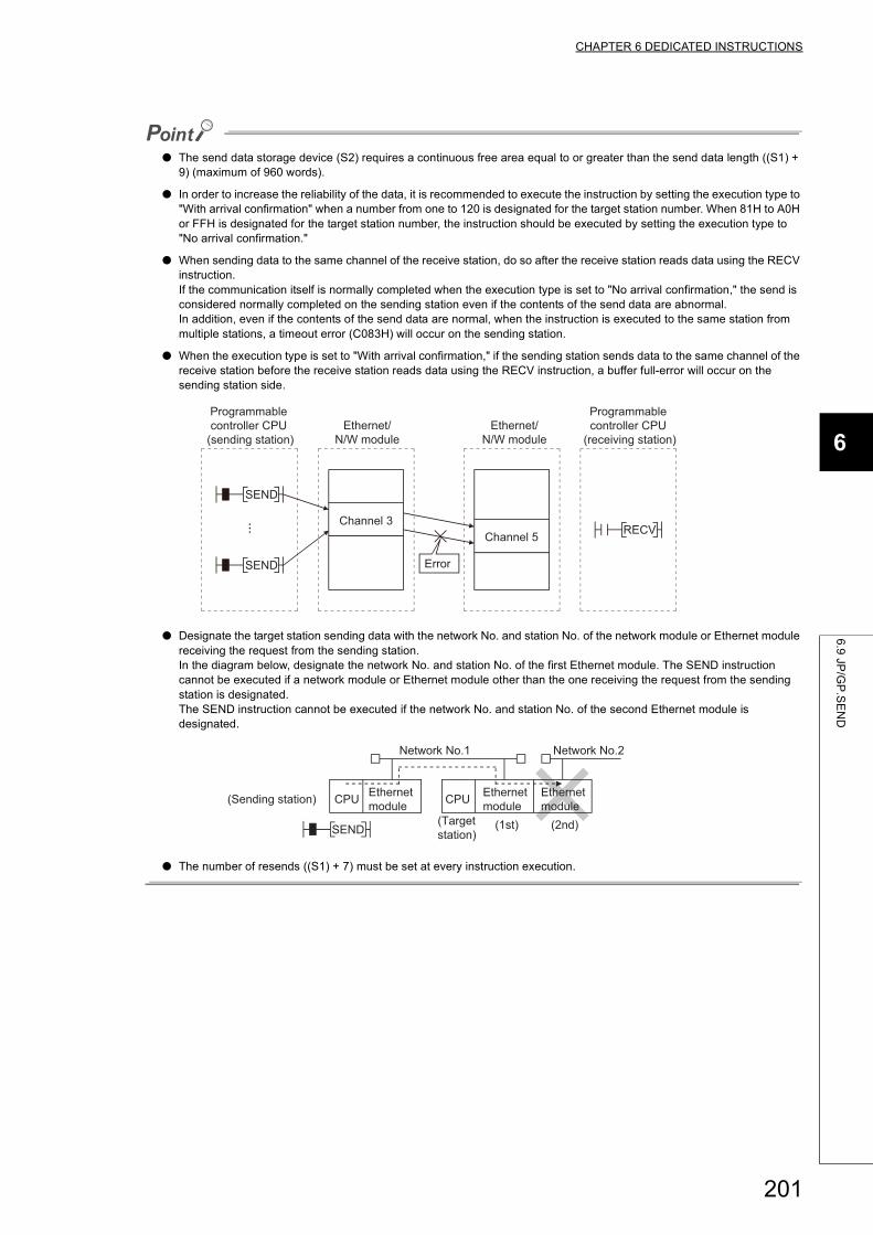
CHAPTER 6 DEDICATED INSTRUCTIONS
6
6.9
JP/G
P.S
EN
D
● The send data storage device (S2) requires a continuous free area equal to or greater than the send data length ((S1) + 9) (maximum of 960 words).
● In order to increase the reliability of the data, it is recommended to execute the instruction by setting the execution type to "With arrival confirmation" when a number from one to 120 is designated for the target station number. When 81H to A0H or FFH is designated for the target station number, the instruction should be executed by setting the execution type to "No arrival confirmation."
● When sending data to the same channel of the receive station, do so after the receive station reads data using the RECV instruction.If the communication itself is normally completed when the execution type is set to "No arrival confirmation," the send is considered normally completed on the sending station even if the contents of the send data are abnormal.In addition, even if the contents of the send data are normal, when the instruction is executed to the same station from multiple stations, a timeout error (C083H) will occur on the sending station.
● When the execution type is set to "With arrival confirmation," if the sending station sends data to the same channel of the receive station before the receive station reads data using the RECV instruction, a buffer full-error will occur on the sending station side.
● Designate the target station sending data with the network No. and station No. of the network module or Ethernet module receiving the request from the sending station.In the diagram below, designate the network No. and station No. of the first Ethernet module. The SEND instruction cannot be executed if a network module or Ethernet module other than the one receiving the request from the sending station is designated.The SEND instruction cannot be executed if the network No. and station No. of the second Ethernet module is designated.
● The number of resends ((S1) + 7) must be set at every instruction execution.
RECV
SEND
SEND
Programmable controller CPU
(sending station)Ethernet/
N/W module
Programmable controller CPU
(receiving station)Ethernet/
N/W module
Channel 5Channel 3
Error
CPUCPU
SEND
Ethernet module
Ethernet module
(2nd)(1st)(Target station)
Ethernet module
Network No.2Network No.1
(Sending station)
201
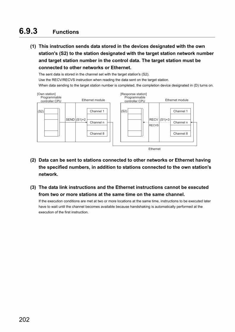
6.9.3 Functions
(1) This instruction sends data stored in the devices designated with the own
station's (S2) to the station designated with the target station network number
and target station number in the control data. The target station must be
connected to other networks or Ethernet.The sent data is stored in the channel set with the target station's (S2).
Use the RECV/RECVS instruction when reading the data sent on the target station.
When data sending to the target station number is completed, the completion device designated in (D) turns on.
(2) Data can be sent to stations connected to other networks or Ethernet having
the specified numbers, in addition to stations connected to the own station's
network.
(3) The data link instructions and the Ethernet instructions cannot be executed
from two or more stations at the same time on the same channel.If the execution conditions are met at two or more locations at the same time, instructions to be executed later
have to wait until the channel becomes available because handshaking is automatically performed at the
execution of the first instruction.
SEND
(S2)
(S1)+2 RECV
(S2)
(S1)+3
RECVS
Ethernet
Channel 1
Channel 8
Programmable controller CPU
Channel 1
Channel 8
Programmable controller CPU
[Own station] [Response station]
Ethernet module Ethernet module
Channel n Channel n
202
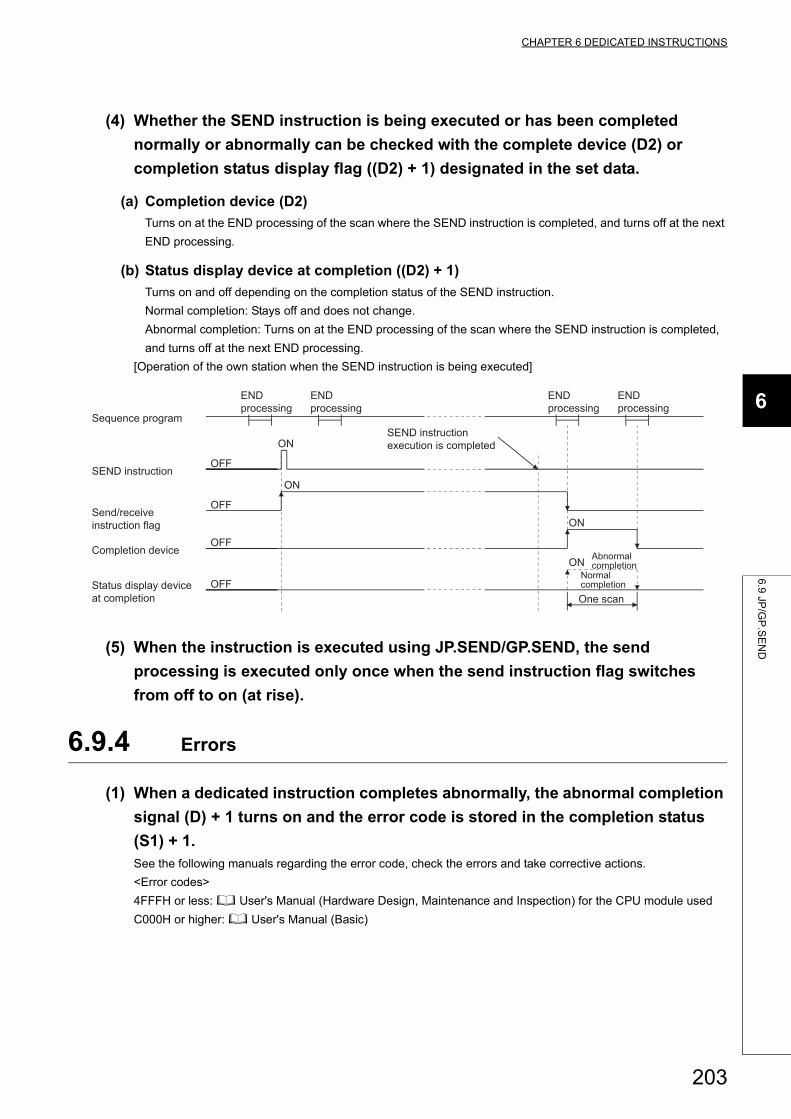
CHAPTER 6 DEDICATED INSTRUCTIONS
6
6.9
JP/G
P.S
EN
D
(4) Whether the SEND instruction is being executed or has been completed
normally or abnormally can be checked with the complete device (D2) or
completion status display flag ((D2) + 1) designated in the set data.
(a) Completion device (D2)
Turns on at the END processing of the scan where the SEND instruction is completed, and turns off at the next
END processing.
(b) Status display device at completion ((D2) + 1)
Turns on and off depending on the completion status of the SEND instruction.
Normal completion: Stays off and does not change.
Abnormal completion: Turns on at the END processing of the scan where the SEND instruction is completed,
and turns off at the next END processing.
[Operation of the own station when the SEND instruction is being executed]
(5) When the instruction is executed using JP.SEND/GP.SEND, the send
processing is executed only once when the send instruction flag switches
from off to on (at rise).
6.9.4 Errors
(1) When a dedicated instruction completes abnormally, the abnormal completion
signal (D) + 1 turns on and the error code is stored in the completion status
(S1) + 1.See the following manuals regarding the error code, check the errors and take corrective actions.
<Error codes>
4FFFH or less: User's Manual (Hardware Design, Maintenance and Inspection) for the CPU module used
C000H or higher: User's Manual (Basic)
ON
OFF
OFF
ON
OFF
ON
OFF
ON Abnormal completion
END processing
END processing
END processing
END processing
Status display device at completion
SEND instruction
One scan
Normal completion
Completion device
Send/receive instruction flag
SEND instruction execution is completed
Sequence program
203
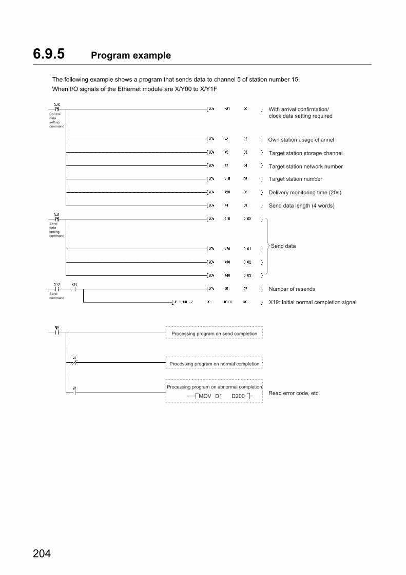
6.9.5 Program example
The following example shows a program that sends data to channel 5 of station number 15.
When I/O signals of the Ethernet module are X/Y00 to X/Y1F
X19: Initial normal completion signal
With arrival confirmation/clock data setting required
Send command
Send data setting command
Control data setting command
D200D1MOV
Processing program on abnormal completion
Processing program on normal completion
Processing program on send completion
Send data
Number of resends
Target station number
Target station storage channel
Delivery monitoring time (20s)
Read error code, etc.
Send data length (4 words)
Target station network number
Own station usage channel
204
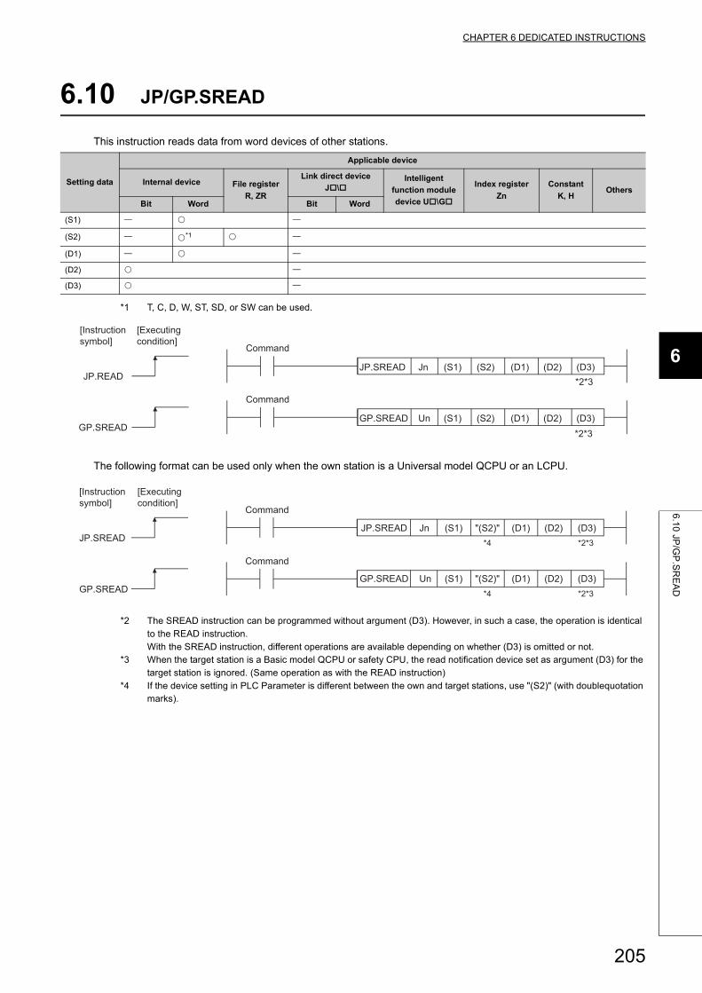
CHAPTER 6 DEDICATED INSTRUCTIONS
6
6.10 JP/G
P.S
RE
AD
6.10 JP/GP.SREAD
This instruction reads data from word devices of other stations.
*1 T, C, D, W, ST, SD, or SW can be used.
The following format can be used only when the own station is a Universal model QCPU or an LCPU.
*2 The SREAD instruction can be programmed without argument (D3). However, in such a case, the operation is identical to the READ instruction.With the SREAD instruction, different operations are available depending on whether (D3) is omitted or not.
*3 When the target station is a Basic model QCPU or safety CPU, the read notification device set as argument (D3) for the target station is ignored. (Same operation as with the READ instruction)
*4 If the device setting in PLC Parameter is different between the own and target stations, use "(S2)" (with doublequotation marks).
Setting data
Applicable device
Internal device File register
R, ZR
Link direct device
J\Intelligent
function module
device U\G
Index register
Zn
Constant
K, HOthers
Bit Word Bit Word
(S1)
(S2) *1
(D1)
(D2)
(D3)
(D3)(D2)(D1)(S2)(S1)
(D3)
GP.SREADUnGP.SREAD
(D2)JP.READ
(D1)(S2)(S1)JnJP.SREAD
*2*3
*2*3
[Executing condition]
[Instruction symbol]
Command
Command
"(S2)" (D3)(D2)(D1)(S1)
(D3)
GP.SREADUnGP.SREAD
(D2)JP.SREAD
(D1)"(S2)"(S1)JnJP.SREAD*4
*4 *2*3
*2*3
[Executing condition]
[Instruction symbol]
Command
Command
205
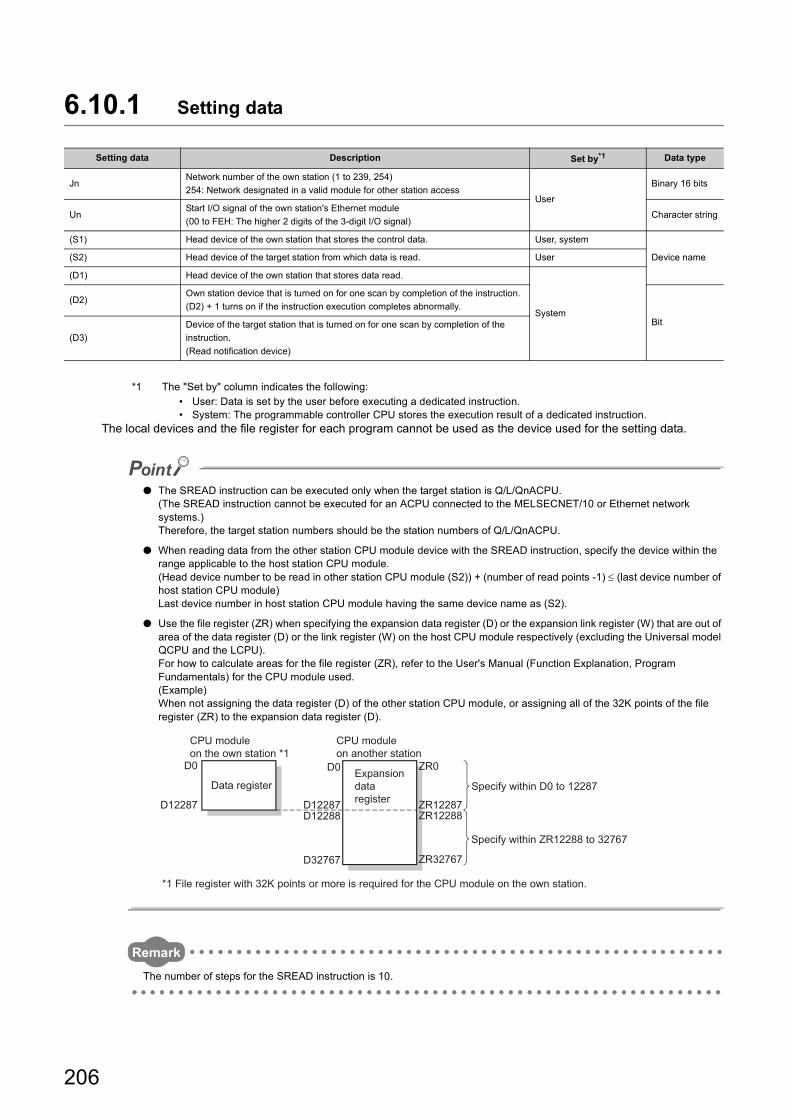
6.10.1 Setting data
*1 The "Set by" column indicates the following:• User: Data is set by the user before executing a dedicated instruction.• System: The programmable controller CPU stores the execution result of a dedicated instruction.
The local devices and the file register for each program cannot be used as the device used for the setting data.
● The SREAD instruction can be executed only when the target station is Q/L/QnACPU.(The SREAD instruction cannot be executed for an ACPU connected to the MELSECNET/10 or Ethernet network systems.)Therefore, the target station numbers should be the station numbers of Q/L/QnACPU.
● When reading data from the other station CPU module device with the SREAD instruction, specify the device within the range applicable to the host station CPU module.(Head device number to be read in other station CPU module (S2)) + (number of read points -1) (last device number of host station CPU module)Last device number in host station CPU module having the same device name as (S2).
● Use the file register (ZR) when specifying the expansion data register (D) or the expansion link register (W) that are out of area of the data register (D) or the link register (W) on the host CPU module respectively (excluding the Universal model QCPU and the LCPU).For how to calculate areas for the file register (ZR), refer to the User's Manual (Function Explanation, Program Fundamentals) for the CPU module used.(Example)When not assigning the data register (D) of the other station CPU module, or assigning all of the 32K points of the file register (ZR) to the expansion data register (D).
Remark
The number of steps for the SREAD instruction is 10.
Setting data Description Set by*1 Data type
JnNetwork number of the own station (1 to 239, 254)
254: Network designated in a valid module for other station accessUser
Binary 16 bits
UnStart I/O signal of the own station's Ethernet module
(00 to FEH: The higher 2 digits of the 3-digit I/O signal)Character string
(S1) Head device of the own station that stores the control data. User, system
Device name(S2) Head device of the target station from which data is read. User
(D1) Head device of the own station that stores data read.
System
(D2)Own station device that is turned on for one scan by completion of the instruction.
(D2) + 1 turns on if the instruction execution completes abnormally.
Bit
(D3)
Device of the target station that is turned on for one scan by completion of the
instruction.
(Read notification device)
ZR0
ZR12287
ZR32767
ZR12288D12287
D32767
D12288D12287
D0D0
Specify within ZR12288 to 32767
Specify within D0 to 12287Expansion data register
CPU module on another station
*1 File register with 32K points or more is required for the CPU module on the own station.
CPU module on the own station *1
Data register
206
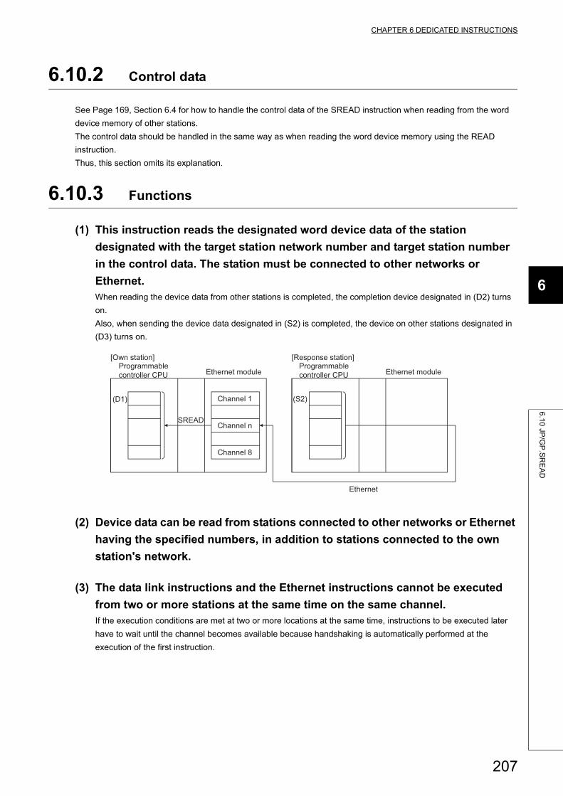
CHAPTER 6 DEDICATED INSTRUCTIONS
6
6.10 JP/G
P.S
RE
AD
6.10.2 Control data
See Page 169, Section 6.4 for how to handle the control data of the SREAD instruction when reading from the word
device memory of other stations.
The control data should be handled in the same way as when reading the word device memory using the READ
instruction.
Thus, this section omits its explanation.
6.10.3 Functions
(1) This instruction reads the designated word device data of the station
designated with the target station network number and target station number
in the control data. The station must be connected to other networks or
Ethernet.When reading the device data from other stations is completed, the completion device designated in (D2) turns
on.
Also, when sending the device data designated in (S2) is completed, the device on other stations designated in
(D3) turns on.
(2) Device data can be read from stations connected to other networks or Ethernet
having the specified numbers, in addition to stations connected to the own
station's network.
(3) The data link instructions and the Ethernet instructions cannot be executed
from two or more stations at the same time on the same channel.If the execution conditions are met at two or more locations at the same time, instructions to be executed later
have to wait until the channel becomes available because handshaking is automatically performed at the
execution of the first instruction.
Ethernet
(D1) (S2)
SREAD
Programmable controller CPU
Channel 1
Channel 8
Programmable controller CPU
[Own station] [Response station]
Ethernet module Ethernet module
Channel n
207
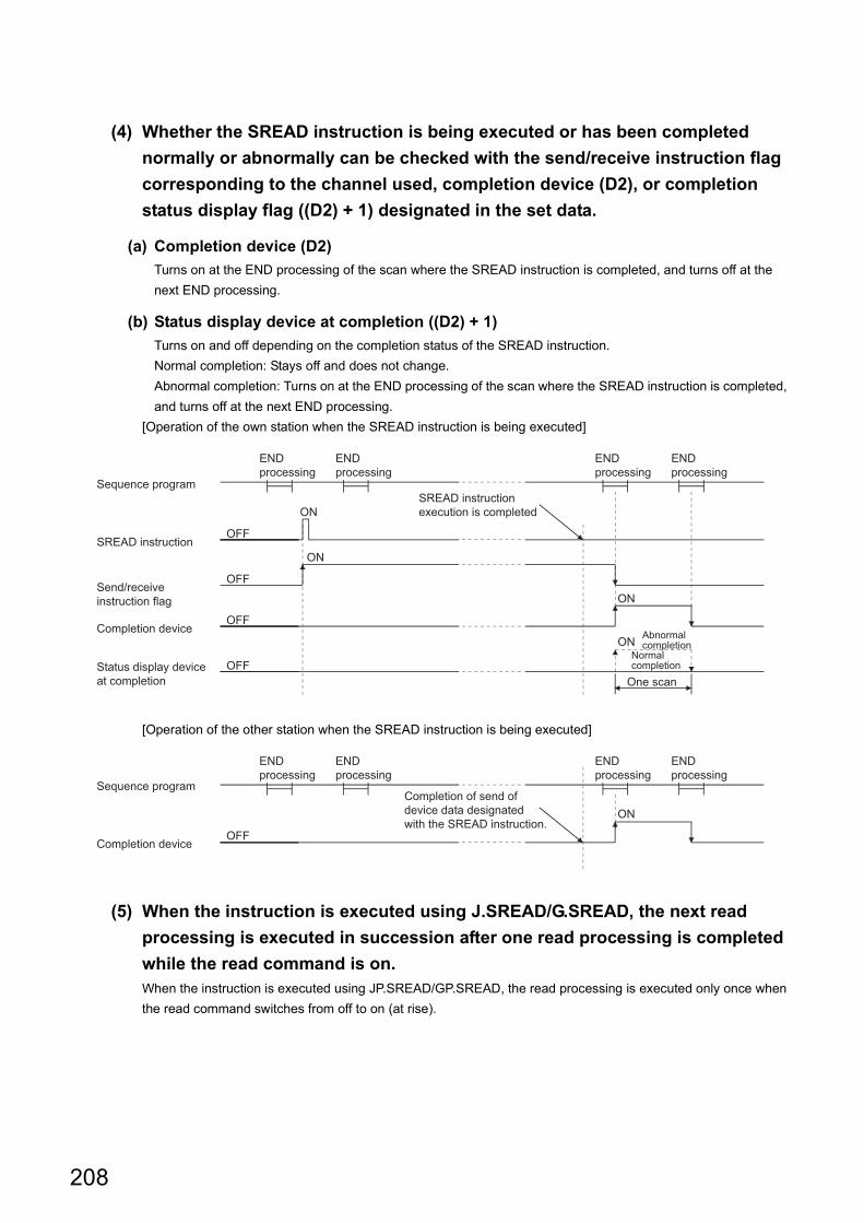
(4) Whether the SREAD instruction is being executed or has been completed
normally or abnormally can be checked with the send/receive instruction flag
corresponding to the channel used, completion device (D2), or completion
status display flag ((D2) + 1) designated in the set data.
(a) Completion device (D2)
Turns on at the END processing of the scan where the SREAD instruction is completed, and turns off at the
next END processing.
(b) Status display device at completion ((D2) + 1)
Turns on and off depending on the completion status of the SREAD instruction.
Normal completion: Stays off and does not change.
Abnormal completion: Turns on at the END processing of the scan where the SREAD instruction is completed,
and turns off at the next END processing.
[Operation of the own station when the SREAD instruction is being executed]
[Operation of the other station when the SREAD instruction is being executed]
(5) When the instruction is executed using J.SREAD/G.SREAD, the next read
processing is executed in succession after one read processing is completed
while the read command is on.When the instruction is executed using JP.SREAD/GP.SREAD, the read processing is executed only once when
the read command switches from off to on (at rise).
ON
OFF
OFF
ON
OFF
ON
OFF
ON Abnormal completion
END processing
END processing
SREAD instruction execution is completed
END processing
END processing
Status display device at completion One scan
Normal completion
Completion device
Send/receive instruction flag
SREAD instruction
Sequence program
ON
OFF
END processing
END processing
Completion of send of device data designated with the SREAD instruction.
END processing
END processing
Completion device
Sequence program
208
CHAPTER 6 DEDICATED INSTRUCTIONS
6
6.10 JP/G
P.S
RE
AD
6.10.4 Errors
(1) When a dedicated instruction completes abnormally, the abnormal completion
signal (D2) + 1 turns on and the error code is stored in the completion status
(S1) + 1.See the following manuals regarding the error code, check the errors and take corrective actions.
<Error codes>
4FFFH or less: User's Manual (Hardware Design, Maintenance and Inspection) for the CPU module used
C000H or higher: User's Manual (Basic)
6.10.5 Program example
See the program example of the READ instruction described in Page 169, Section 6.4.
The SREAD instruction only differs from the READ instruction on one point, namely that the read notification device
(D3) is designated at the end of arguments.
209
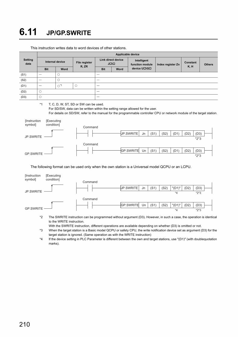
6.11 JP/GP.SWRITE
This instruction writes data to word devices of other stations.
*1 T, C, D, W, ST, SD or SW can be used.For SD/SW, data can be written within the setting range allowed for the user.For details on SD/SW, refer to the manual for the programmable controller CPU or network module of the target station.
The following format can be used only when the own station is a Universal model QCPU or an LCPU.
*2 The SWRITE instruction can be programmed without argument (D3). However, in such a case, the operation is identical to the WRITE instruction.With the SWRITE instruction, different operations are available depending on whether (D3) is omitted or not.
*3 When the target station is a Basic model QCPU or safety CPU, the write notification device set as argument (D3) for the target station is ignored. (Same operation as with the WRITE instruction)
*4 If the device setting in PLC Parameter is different between the own and target stations, use "(D1)" (with doublequotation marks).
Setting
data
Applicable device
Internal device File register
R, ZR
Link direct device
J\Intelligent
function module
device U\G
Index register ZnConstant
K, HOthers
Bit Word Bit Word
(S1)
(S2)
(D1) *1
(D2)
(D3)
GP.SWRITE
JP.SWRITE
(D3)(D2)(D1)(S2)(S1)
(D3)
GP.SWRITEUn
(D2)JP.SWRITE
(D1)(S2)(S1)Jn
*2*3
*2*3
[Executing condition]
[Instruction symbol]
Command
Command
GP.SWRITE
JP.SWRITE
"(D1)" (D3)(D2)(S2)(S1)
(D3)
GP.SWRITEUn
(D2)JP.SWRITE
"(D1)"(S2)(S1)Jn
*2*3
*2*3*4
*4
[Executing condition]
[Instruction symbol]
Command
Command
210
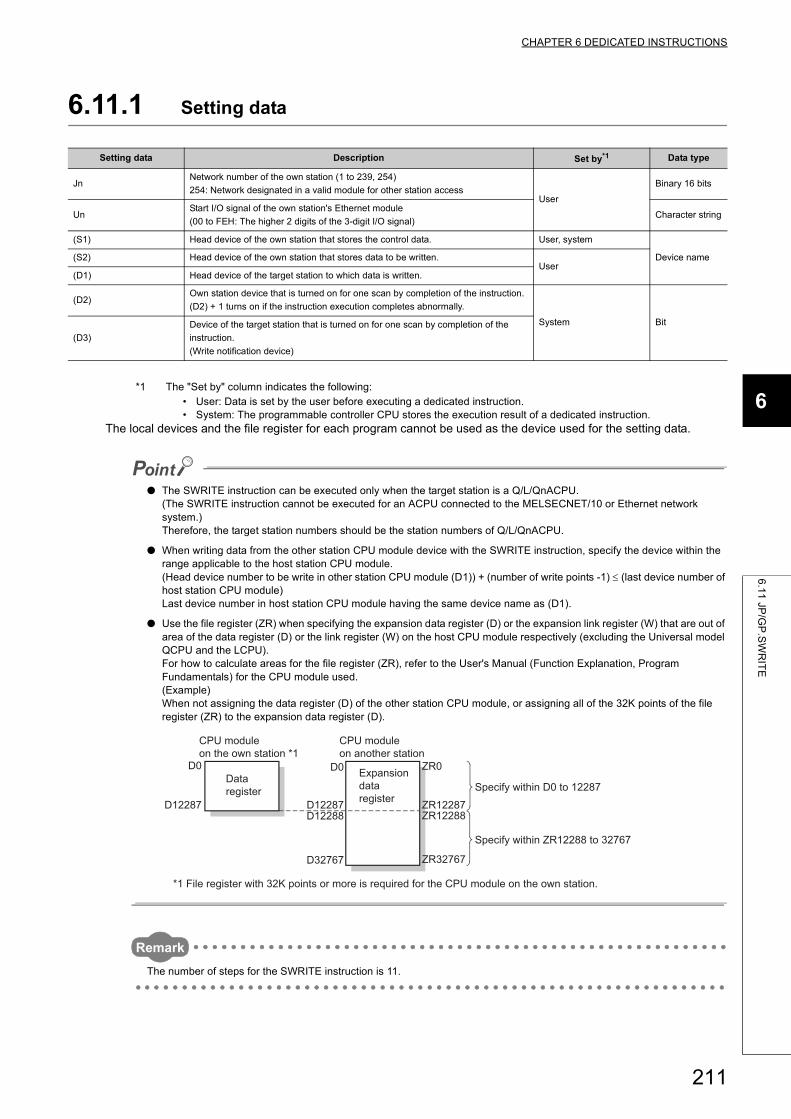
CHAPTER 6 DEDICATED INSTRUCTIONS
6
6.1
1 JP
/GP
.SW
RIT
E
6.11.1 Setting data
*1 The "Set by" column indicates the following:• User: Data is set by the user before executing a dedicated instruction.• System: The programmable controller CPU stores the execution result of a dedicated instruction.
The local devices and the file register for each program cannot be used as the device used for the setting data.
● The SWRITE instruction can be executed only when the target station is a Q/L/QnACPU.(The SWRITE instruction cannot be executed for an ACPU connected to the MELSECNET/10 or Ethernet network system.)Therefore, the target station numbers should be the station numbers of Q/L/QnACPU.
● When writing data from the other station CPU module device with the SWRITE instruction, specify the device within the range applicable to the host station CPU module.(Head device number to be write in other station CPU module (D1)) + (number of write points -1) (last device number of host station CPU module)Last device number in host station CPU module having the same device name as (D1).
● Use the file register (ZR) when specifying the expansion data register (D) or the expansion link register (W) that are out of area of the data register (D) or the link register (W) on the host CPU module respectively (excluding the Universal model QCPU and the LCPU).For how to calculate areas for the file register (ZR), refer to the User's Manual (Function Explanation, Program Fundamentals) for the CPU module used.(Example)When not assigning the data register (D) of the other station CPU module, or assigning all of the 32K points of the file register (ZR) to the expansion data register (D).
Remark
The number of steps for the SWRITE instruction is 11.
Setting data Description Set by*1 Data type
JnNetwork number of the own station (1 to 239, 254)
254: Network designated in a valid module for other station accessUser
Binary 16 bits
UnStart I/O signal of the own station's Ethernet module
(00 to FEH: The higher 2 digits of the 3-digit I/O signal)Character string
(S1) Head device of the own station that stores the control data. User, system
Device name(S2) Head device of the own station that stores data to be written.User
(D1) Head device of the target station to which data is written.
(D2)Own station device that is turned on for one scan by completion of the instruction.
(D2) + 1 turns on if the instruction execution completes abnormally.
System Bit
(D3)
Device of the target station that is turned on for one scan by completion of the
instruction.
(Write notification device)
ZR0
ZR12287
ZR32767
ZR12288D12287
D32767
D12288D12287
D0D0
Specify within ZR12288 to 32767
Specify within D0 to 12287
CPU module on another station
CPU module on the own station *1
*1 File register with 32K points or more is required for the CPU module on the own station.
Data register
Expansion data register
211
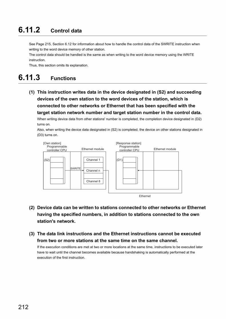
6.11.2 Control data
See Page 215, Section 6.12 for information about how to handle the control data of the SWRITE instruction when
writing to the word device memory of other station.
The control data should be handled is the same as when writing to the word device memory using the WRITE
instruction.
Thus, this section omits its explanation.
6.11.3 Functions
(1) This instruction writes data in the device designated in (S2) and succeeding
devices of the own station to the word devices of the station, which is
connected to other networks or Ethernet that has been specified with the
target station network number and target station number in the control data.When writing device data from other stations' number is completed, the completion device designated in (D2)
turns on.
Also, when writing the device data designated in (S2) is completed, the device on other stations designated in
(D3) turns on.
(2) Device data can be written to stations connected to other networks or Ethernet
having the specified numbers, in addition to stations connected to the own
station's network.
(3) The data link instructions and the Ethernet instructions cannot be executed
from two or more stations at the same time on the same channel.If the execution conditions are met at two or more locations at the same time, instructions to be executed later
have to wait until the channel becomes available because handshaking is automatically performed at the
execution of the first instruction.
Ethernet
(S2) (D1)
SWRITE
Programmable controller CPU
Channel 1
Channel 8
Programmable controller CPU
[Own station] [Response station]
Ethernet module Ethernet module
Channel n
212
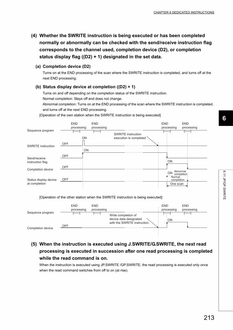
CHAPTER 6 DEDICATED INSTRUCTIONS
6
6.1
1 JP
/GP
.SW
RIT
E
(4) Whether the SWRITE instruction is being executed or has been completed
normally or abnormally can be checked with the send/receive instruction flag
corresponds to the channel used, completion device (D2), or completion
status display flag ((D2) + 1) designated in the set data.
(a) Completion device (D2)
Turns on at the END processing of the scan where the SWRITE instruction is completed, and turns off at the
next END processing.
(b) Status display device at completion ((D2) + 1)
Turns on and off depending on the completion status of the SWRITE instruction.
Normal completion: Stays off and does not change.
Abnormal completion: Turns on at the END processing of the scan where the SWRITE instruction is completed,
and turns off at the next END processing.
[Operation of the own station when the SWRITE instruction is being executed]
[Operation of the other station when the SWRITE instruction is being executed]
(5) When the instruction is executed using J.SWRITE/G.SWRITE, the next read
processing is executed in succession after one read processing is completed
while the read command is on.When the instruction is executed using JP.SWRITE /GP.SWRITE, the read processing is executed only once
when the read command switches from off to on (at rise).
ON
OFF
OFF
ON
OFF
ON
OFF
ON
One scan
Abnormal completion
END processing
END processing
END processing
END processing
Status display device at completion
Normal completion
Completion device
Send/receive instruction flag
SWRITE instruction execution is completed
SWRITE instruction
Sequence program
ON
OFF
END processing
END processing
Write completion of device data designated with the SWRITE instruction.
END processing
END processing
Completion device
Sequence program
213
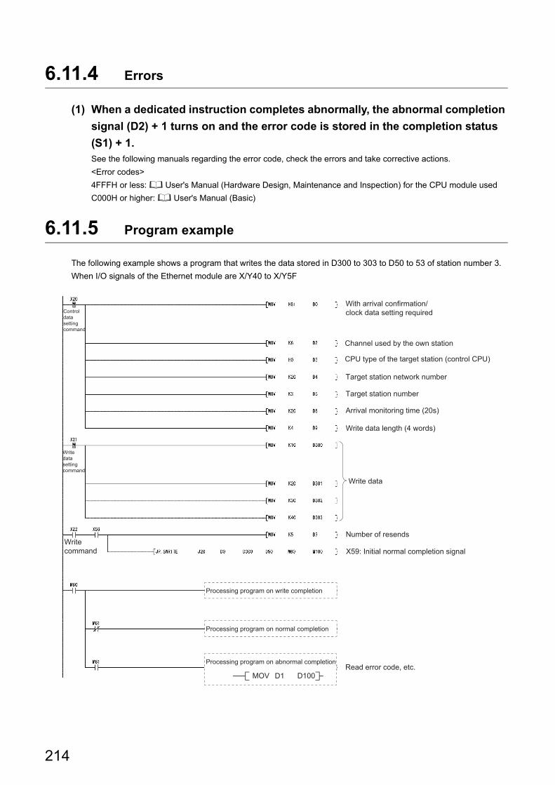
6.11.4 Errors
(1) When a dedicated instruction completes abnormally, the abnormal completion
signal (D2) + 1 turns on and the error code is stored in the completion status
(S1) + 1.See the following manuals regarding the error code, check the errors and take corrective actions.
<Error codes>
4FFFH or less: User's Manual (Hardware Design, Maintenance and Inspection) for the CPU module used
C000H or higher: User's Manual (Basic)
6.11.5 Program example
The following example shows a program that writes the data stored in D300 to 303 to D50 to 53 of station number 3.
When I/O signals of the Ethernet module are X/Y40 to X/Y5F
Channel used by the own station
Target station network number
Write data length (4 words)
Read error code, etc.
Arrival monitoring time (20s)
Target station number
Number of resends
Write data
Processing program on write completion
Processing program on normal completion
Processing program on abnormal completion
MOV D1 D100
Control data setting command
Write data setting command
Write command
With arrival confirmation/clock data setting required
CPU type of the target station (control CPU)
X59: Initial normal completion signal
214
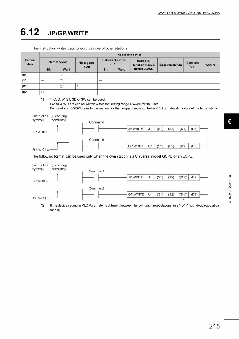
CHAPTER 6 DEDICATED INSTRUCTIONS
6
6.1
2 JP
/GP
.WR
ITE
6.12 JP/GP.WRITE
This instruction writes data to word devices of other stations.
*1 T, C, D, W, ST, SD or SW can be used.For SD/SW, data can be written within the setting range allowed for the user.For details on SD/SW, refer to the manual for the programmable controller CPU or network module of the target station.
The following format can be used only when the own station is a Universal model QCPU or an LCPU.
*2 If the device setting in PLC Parameter is different between the own and target stations, use "(D1)" (with doublequotation marks).
Setting
data
Applicable device
Internal device File register
R, ZR
Link direct device
J\Intelligent
function module
device U\G
Index register ZnConstant
K, HOthers
Bit Word Bit Word
(S1)
(S2)
(D1) *1
(D2)
GP.WRITE
JP.WRITE
(D2)(D1)(S2)(S1)UnGP.WRITE
(D2)(D1)(S2)(S1)JnJP.WRITE
[Executing condition]
[Instruction symbol]
Command
Command
"(D1)" (D2)(S2)(S1)GP.WRITE
UnGP.WRITE
(D2)JP.WRITE
"(D1)"(S2)(S1)JnJP.WRITE*2
*2
[Executing condition]
[Instruction symbol]
Command
Command
215

6.12.1 Setting data
*1 The "Set by" column indicates the following:• User: Data is set by the user before executing a dedicated instruction.• System: The programmable controller CPU stores the execution result of a dedicated instruction.
The local devices and the file register for each program cannot be used as the device used for the setting data.
● The WRITE instruction can be executed only when the target station is the Q/L/QnACPU.(The WRITE instruction cannot be executed for an ACPU connected to the MELSECNET/10 or Ethernet network systems.)Therefore, the target station numbers should be the station numbers of Q/L/QnACPU.
● When writing data from the other station CPU module device with the WRITE instruction, specify the device within the range applicable to the host station CPU module.(Head device number to be write in other station CPU module (D1)) + (number of write points -1) (last device number of host station CPU module)Last device number in host station CPU module having the same device name as (D1).
● Use the file register (ZR) when specifying the expansion data register (D) or the expansion link register (W) that are out of area of the data register (D) or the link register (W) on the host CPU module respectively (excluding the Universal model QCPU and the LCPU).For how to calculate areas for the file register (ZR), refer to the User's Manual (Function Explanation, Program Fundamentals) for the CPU module used.(Example)When not assigning the data register (D) of the other station CPU module, or assigning all of the 32K points of the file register (ZR) to the expansion data register (D).
Remark
● Setting values stored in Completion status ((S1) + 1) and Clock data ((S1) + 10 to (S1) + 14) are stored into control data upon completion of the instruction.
● The number of steps for the WRITE instruction is 10.
Setting data Description Set by*1 Data type
JnNetwork number of the own station (1 to 239, 254)
254: Network designated in a valid module for other station accessUser
Binary 16 bits
UnStart I/O signal of the own station's Ethernet module
(00 to FEH: The higher 2 digits of the 3-digit I/O signal)Character string
(S1) Head device of the own station that stores the control data. User, system
Device name(S2) Head device of the own station that stores data to be written.User
(D1) Head device of the target station to which data is written.
(D2)Own station device that is turned on for one scan by completion of the instruction.
(D2) + 1 turns on if the instruction execution completes abnormally.System Bit
ZR0
ZR12287
ZR32767
ZR12288D12287
D32767
D12288D12287
D0D0Expansion data register
Specify within D0 to 12287
Specify within ZR12288 to 32767
*1 File register with 32K points or more is required for the CPU module on the own station.
CPU module on another station
CPU module on the own station *1
Data register
216
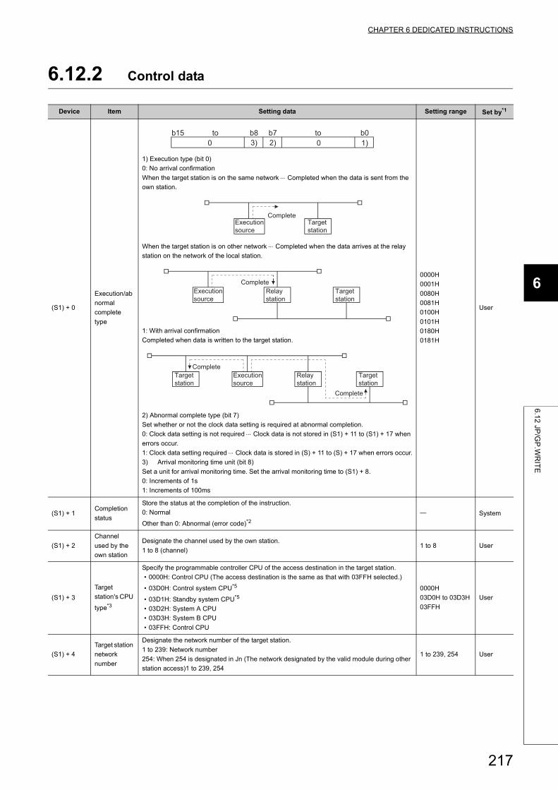
CHAPTER 6 DEDICATED INSTRUCTIONS
6
6.1
2 JP
/GP
.WR
ITE
6.12.2 Control data
Device Item Setting data Setting range Set by*1
(S1) + 0
Execution/ab
normal
complete
type
1) Execution type (bit 0)
0: No arrival confirmation
When the target station is on the same network Completed when the data is sent from the
own station.
When the target station is on other network Completed when the data arrives at the relay
station on the network of the local station.
1: With arrival confirmation
Completed when data is written to the target station.
2) Abnormal complete type (bit 7)
Set whether or not the clock data setting is required at abnormal completion.
0: Clock data setting is not required Clock data is not stored in (S1) + 11 to (S1) + 17 when
errors occur.
1: Clock data setting required Clock data is stored in (S) + 11 to (S) + 17 when errors occur.
3) Arrival monitoring time unit (bit 8)
Set a unit for arrival monitoring time. Set the arrival monitoring time to (S1) + 8.
0: Increments of 1s
1: Increments of 100ms
0000H
0001H
0080H
0081H
0100H
0101H
0180H
0181H
User
(S1) + 1Completion
status
Store the status at the completion of the instruction.
0: Normal
Other than 0: Abnormal (error code)*2 System
(S1) + 2
Channel
used by the
own station
Designate the channel used by the own station.
1 to 8 (channel)1 to 8 User
(S1) + 3
Target
station's CPU
type*3
Specify the programmable controller CPU of the access destination in the target station.
• 0000H: Control CPU (The access destination is the same as that with 03FFH selected.)
• 03D0H: Control system CPU*5
• 03D1H: Standby system CPU*5
• 03D2H: System A CPU
• 03D3H: System B CPU
• 03FFH: Control CPU
0000H
03D0H to 03D3H
03FFH
User
(S1) + 4
Target station
network
number
Designate the network number of the target station.
1 to 239: Network number
254: When 254 is designated in Jn (The network designated by the valid module during other
station access)1 to 239, 254
1 to 239, 254 User
3)b8
02) 1)0b0b7b15 toto
CompleteTarget station
Execution source
CompleteTarget station
Relay station
Execution source
Complete
CompleteTarget station
Target station
Relay station
Execution source
217
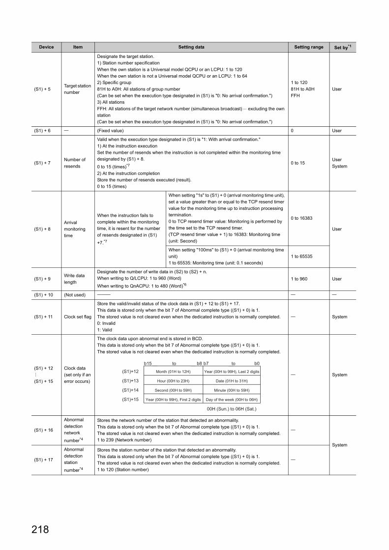
(S1) + 5Target station
number
Designate the target station.
1) Station number specification
When the own station is a Universal model QCPU or an LCPU: 1 to 120
When the own station is not a Universal model QCPU or an LCPU: 1 to 64
2) Specific group
81H to A0H: All stations of group number
(Can be set when the execution type designated in (S1) is "0: No arrival confirmation.")
3) All stations
FFH: All stations of the target network number (simultaneous broadcast) excluding the own
station
(Can be set when the execution type designated in (S1) is "0: No arrival confirmation.")
1 to 120
81H to A0H
FFH
User
(S1) + 6 (Fixed value) 0 User
(S1) + 7Number of
resends
Valid when the execution type designated in (S1) is "1: With arrival confirmation."
1) At the instruction execution
Set the number of resends when the instruction is not completed within the monitoring time
designated by (S1) + 8.
0 to 15 (times)*7
2) At the instruction completion
Store the number of resends executed (result).
0 to 15 (times)
0 to 15User
System
(S1) + 8
Arrival
monitoring
time
When the instruction fails to
complete within the monitoring
time, it is resent for the number
of resends designated in (S1)
+7.*7
When setting "1s" to (S1) + 0 (arrival monitoring time unit),
set a value greater than or equal to the TCP resend timer
value for the monitoring time up to instruction processing
termination.
0 to TCP resend timer value: Monitoring is performed by
the time set to the TCP resend timer.
(TCP resend timer value + 1) to 16383: Monitoring time
(unit: Second)
0 to 16383
User
When setting "100ms" to (S1) + 0 (arrival monitoring time
unit)
1 to 65535: Monitoring time (unit: 0.1 seconds)
1 to 65535
(S1) + 9Write data
length
Designate the number of write data in (S2) to (S2) + n.
When writing to Q/LCPU: 1 to 960 (Word)
When writing to QnACPU: 1 to 480 (Word)*61 to 960 User
(S1) + 10 (Not used)
(S1) + 11 Clock set flag
Store the valid/invalid status of the clock data in (S1) + 12 to (S1) + 17.
This data is stored only when the bit 7 of Abnormal complete type ((S1) + 0) is 1.
The stored value is not cleared even when the dedicated instruction is normally completed.
0: Invalid
1: Valid
System
(S1) + 12
(S1) + 15
Clock data
(set only if an
error occurs)
The clock data upon abnormal end is stored in BCD.
This data is stored only when the bit 7 of Abnormal complete type ((S1) + 0) is 1.
The stored value is not cleared even when the dedicated instruction is normally completed.
System
(S1) + 16
Abnormal
detection
network
number*4
Stores the network number of the station that detected an abnormality.
This data is stored only when the bit 7 of Abnormal complete type ((S1) + 0) is 1.
The stored value is not cleared even when the dedicated instruction is normally completed.
1 to 239 (Network number)
System
(S1) + 17
Abnormal
detection
station
number*4
Stores the station number of the station that detected an abnormality.
This data is stored only when the bit 7 of Abnormal complete type ((S1) + 0) is 1.
The stored value is not cleared even when the dedicated instruction is normally completed.
1 to 120 (Station number)
Device Item Setting data Setting range Set by*1
(S1)+15
(S1)+14
(S1)+13
(S1)+12
b0b7b8b15
00H (Sun.) to 06H (Sat.)
Day of the week (00H to 06H)Year (00H to 99H), First 2 digits
Minute (00H to 59H)Second (00H to 59H)
Date (01H to 31H)Hour (00H to 23H)
Year (00H to 99H), Last 2 digitsMonth (01H to 12H)
toto
218
CHAPTER 6 DEDICATED INSTRUCTIONS
6
6.1
2 JP
/GP
.WR
ITE
*1 The "Set by" column indicates the following:• User: Data is set by the user before executing a dedicated instruction.• System: The programmable controller CPU stores the execution result of a dedicated instruction.
*2 For a list of error codes, see the User's Manual (Basic).*3 It can be specified when the own station has an Ethernet module of function version D or later.
(Not available for any other case. Access to the control CPU is required.)*4 Nothing is stored if the execution source detects an error when receiving an instruction.*5 When the WRITE instruction is executed to the redundant system with a control system or standby system CPU
specified, the instruction may be unsuccessfully completed due to system switching occurred on the target station.(Error code: 4244H, 4248H)If this has occurred, execute the WRITE instruction again.
*6 When data of more than 480 words is specified, a C084H error occurs on the own station.Check the write data length (1 to 480 words) and execute the WRITE instruction.
*7 For how to determine the setting values of the number of resends and arrival monitoring time and their setting examples, refer to Page 231, Appendix 1.
● The data written storage device (D1) requires a contiguous free area equal to or greater than the write data length ((S1) + 9) (maximum of 960 words).
● In order to increase the reliability of the data, it is recommended to execute the instruction by setting the execution type to "With arrival confirmation" when a number from one to 120 is designated for the target station number.When 81H to A0H or FFH is designated for the target station number, the instruction should be executed by setting the execution type to "No arrival confirmation."
● When writing to a device of the same station from multiple stations, make sure that the timings of the write operations do not coincide.If the communication itself is normally completed when the execution type is set to "No arrival confirmation," the send is considered normally completed on the write source station even if the contents of the send data are abnormal.In addition, even if the contents of the send data are normal, when the instruction is executed to the same station from multiple stations, a timeout error (C083H) will occur on the write source station.
● The number of resends ((S1) + 7) must be set at every instruction execution.
Remark
The allowable write data length ((S1) + 9) of the WRITE instruction varies depending on the version. ( User's Manual (Basic))Specifying a length value outside the setting range will cause a 4101 error (OPERATION ERROR) on the own station.
219
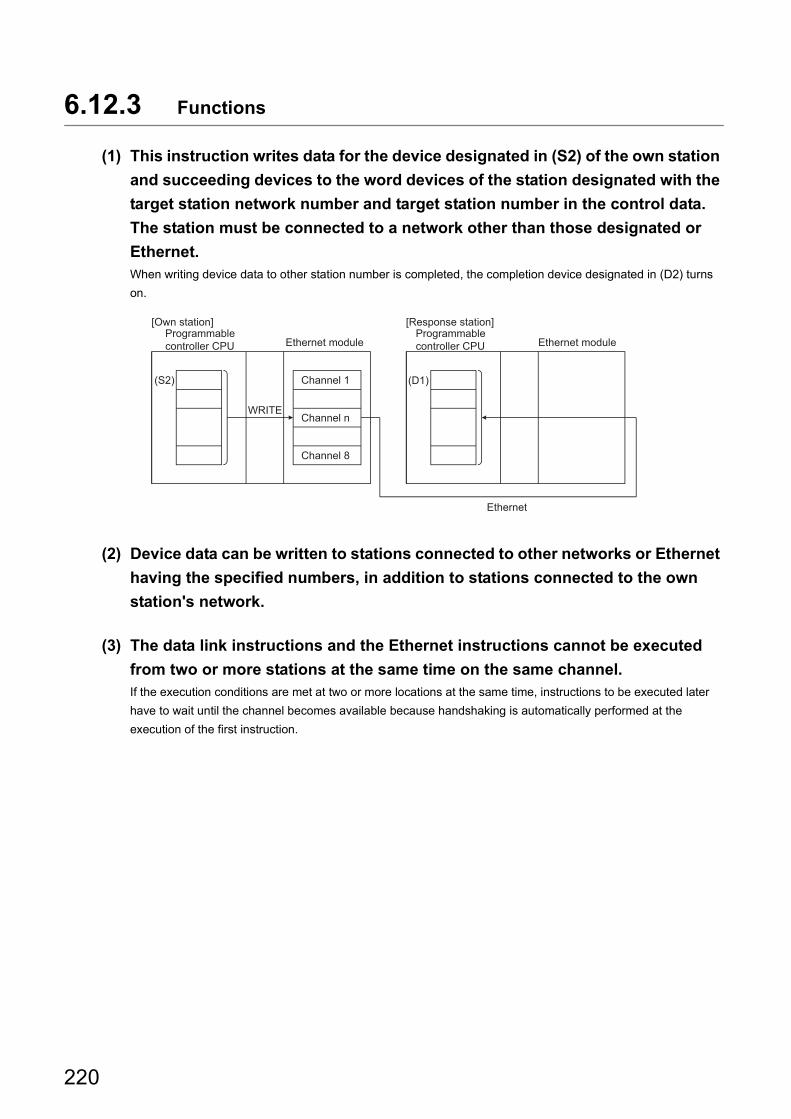
6.12.3 Functions
(1) This instruction writes data for the device designated in (S2) of the own station
and succeeding devices to the word devices of the station designated with the
target station network number and target station number in the control data.
The station must be connected to a network other than those designated or
Ethernet.When writing device data to other station number is completed, the completion device designated in (D2) turns
on.
(2) Device data can be written to stations connected to other networks or Ethernet
having the specified numbers, in addition to stations connected to the own
station's network.
(3) The data link instructions and the Ethernet instructions cannot be executed
from two or more stations at the same time on the same channel.If the execution conditions are met at two or more locations at the same time, instructions to be executed later
have to wait until the channel becomes available because handshaking is automatically performed at the
execution of the first instruction.
Ethernet
(S2) (D1)
WRITE
Programmable controller CPU
Channel 1
Channel 8
Programmable controller CPU
[Own station]
Ethernet module
[Response station]
Ethernet module
Channel n
220
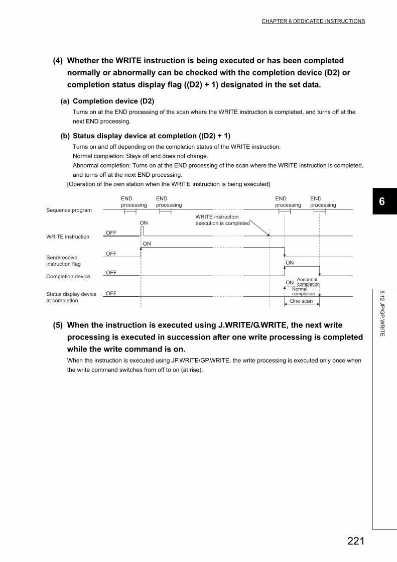
CHAPTER 6 DEDICATED INSTRUCTIONS
6
6.1
2 JP
/GP
.WR
ITE
(4) Whether the WRITE instruction is being executed or has been completed
normally or abnormally can be checked with the completion device (D2) or
completion status display flag ((D2) + 1) designated in the set data.
(a) Completion device (D2)
Turns on at the END processing of the scan where the WRITE instruction is completed, and turns off at the
next END processing.
(b) Status display device at completion ((D2) + 1)
Turns on and off depending on the completion status of the WRITE instruction.
Normal completion: Stays off and does not change.
Abnormal completion: Turns on at the END processing of the scan where the WRITE instruction is completed,
and turns off at the next END processing.
[Operation of the own station when the WRITE instruction is being executed]
(5) When the instruction is executed using J.WRITE/G.WRITE, the next write
processing is executed in succession after one write processing is completed
while the write command is on.When the instruction is executed using JP.WRITE/GP.WRITE, the write processing is executed only once when
the write command switches from off to on (at rise).
ON
OFF
OFF
ON
OFF
ON
OFF
ON
One scan
Abnormal completion
END processing
END processing
END processing
END processing
Status display device at completion
Normal completion
Completion device
Send/receive instruction flag
WRITE instruction execution is completed
WRITE instruction
Sequence program
221
6.12.4 Errors
(1) When a dedicated instruction completes abnormally, the abnormal completion
signal (D2) + 1 turns on and the error code is stored in the completion status
(S1) + 1.See the following manuals regarding the error code, check the errors and take corrective actions.
<Error codes>
4FFFH or less: User's Manual (Hardware Design, Maintenance and Inspection) for the CPU module used
C000H or higher: User's Manual (Basic)
6.12.5 Program example
See the program example of the SWRITE instruction described in Page 210, Section 6.11.
The SWRITE instruction only differs from the WRITE instruction on one point, namely that the write notification device
(D3) is not designated at the end of arguments.
222
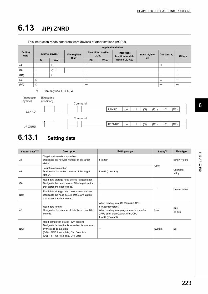
CHAPTER 6 DEDICATED INSTRUCTIONS
6
6.1
3 J(P
).ZN
RD
6.13 J(P).ZNRD
This instruction reads data from word devices of other stations (ACPU).
*1 Can only use T, C, D, W
6.13.1 Setting data
Setting
data
Applicable device
Internal device File register
R, ZR
Link direct device
J\Intelligent
function module
device U\G
Index register
Zn
Constant K,
HOthers
Bit Word Bit Word
n1
(S) *1
(D1)
n2
(D2)
Setting data*1*2 Description Setting range Set by*3 Data type
Jn
Target station network number
Designate the network number of the target
station.
1 to 239
User
Binary 16 bits
n1
Target station number
Designates the station number of the target
station.
1 to 64 (constant)Character
string
(S)
Read data storage head device (target station)
Designate the head device of the target station
that stores the data to read.
Device name
(D1)
Read data storage head device (own station)
Designate the head device of the own station
that stores the data to read.
n2
Read data length
Designates the number of data (word count) to
be read.
When reading from Q/L/QnA/AnUCPU
1 to 230 (constant)
When reading from programmable controller
CPUs other than Q/L/QnA/AnUCPU
1 to 32 (constant)
UserBIN
16 bits
(D2)
Read completion device (own station)
Designate device that is turned on for one scan
by the read completion
(D2) OFF: Incomplete, ON: Complete
(D2) + 1 OFF: Normal, ON: Error
System Bit
JP.ZNRD (D2)(S) (D1) n2n1
(D2)n2
JP.ZNRD
(S) (D1)n1JnJ.ZNRD
Jn
J.ZNRD
[Executing condition]
[Instruction symbol]
Command
Command
223
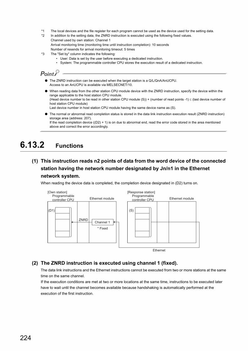
*1 The local devices and the file register for each program cannot be used as the device used for the setting data.*2 In addition to the setting data, the ZNRD instruction is executed using the following fixed values.
Channel used by own station: Channel 1Arrival monitoring time (monitoring time until instruction completion): 10 secondsNumber of resends for arrival monitoring timeout: 5 times
*3 The "Set by" column indicates the following:• User: Data is set by the user before executing a dedicated instruction.• System: The programmable controller CPU stores the execution result of a dedicated instruction.
● The ZNRD instruction can be executed when the target station is a Q/L/QnA/AnUCPU.Access to an AnUCPU is available via MELSECNET/10.
● When reading data from the other station CPU module device with the ZNRD instruction, specify the device within the range applicable to the host station CPU module.(Head device number to be read in other station CPU module (S)) + (number of read points -1) (last device number of host station CPU module)Last device number in host station CPU module having the same device name as (S).
● The normal or abnormal read completion status is stored in the data link instruction execution result (ZNRD instruction) storage area (address: 207).If the read completion device ((D2) + 1) is on due to abnormal end, read the error code stored in the area mentioned above and correct the error accordingly.
6.13.2 Functions
(1) This instruction reads n2 points of data from the word device of the connected
station having the network number designated by Jn/n1 in the Ethernet
network system.When reading the device data is completed, the completion device designated in (D2) turns on.
(2) The ZNRD instruction is executed using channel 1 (fixed).The data link instructions and the Ethernet instructions cannot be executed from two or more stations at the same
time on the same channel.
If the execution conditions are met at two or more locations at the same time, instructions to be executed later
have to wait until the channel becomes available because handshaking is automatically performed at the
execution of the first instruction.
Ethernet
(D1)
ZNRD
Programmable controller CPU
(S)
Programmable controller CPU
Channel 1
[Own station]
Ethernet module
[Response station]
Ethernet module
* Fixed
224
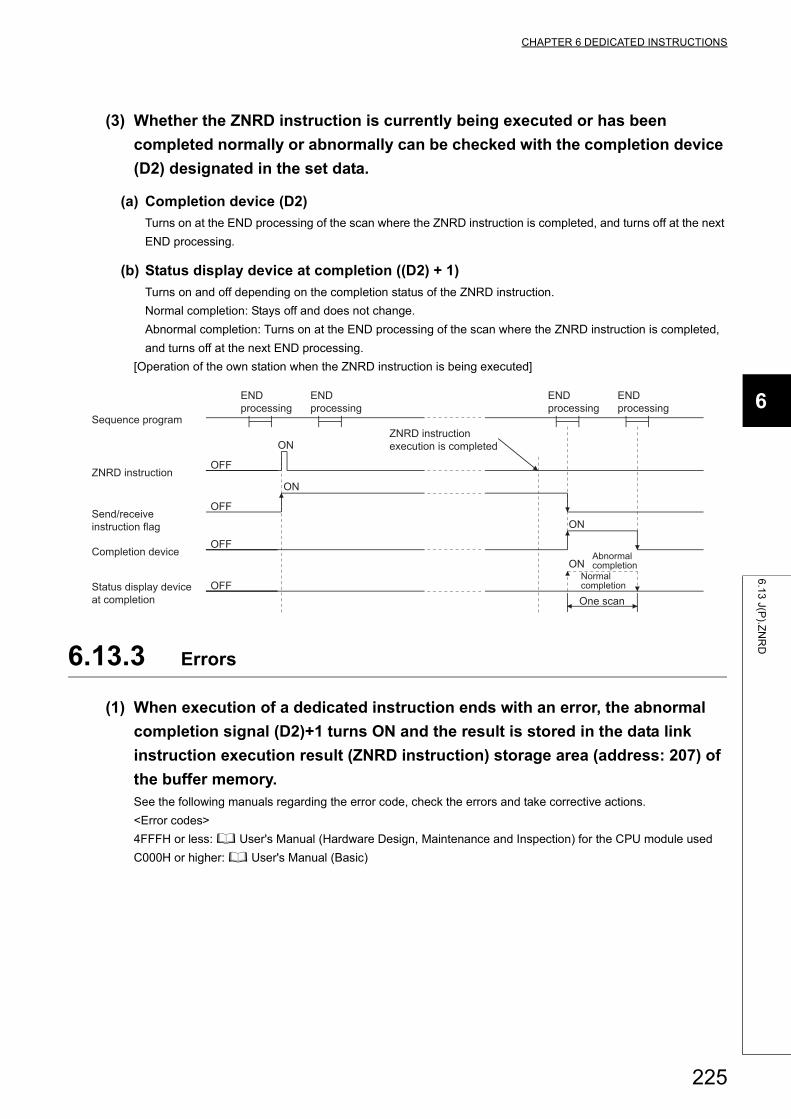
CHAPTER 6 DEDICATED INSTRUCTIONS
6
6.1
3 J(P
).ZN
RD
(3) Whether the ZNRD instruction is currently being executed or has been
completed normally or abnormally can be checked with the completion device
(D2) designated in the set data.
(a) Completion device (D2)
Turns on at the END processing of the scan where the ZNRD instruction is completed, and turns off at the next
END processing.
(b) Status display device at completion ((D2) + 1)
Turns on and off depending on the completion status of the ZNRD instruction.
Normal completion: Stays off and does not change.
Abnormal completion: Turns on at the END processing of the scan where the ZNRD instruction is completed,
and turns off at the next END processing.
[Operation of the own station when the ZNRD instruction is being executed]
6.13.3 Errors
(1) When execution of a dedicated instruction ends with an error, the abnormal
completion signal (D2)+1 turns ON and the result is stored in the data link
instruction execution result (ZNRD instruction) storage area (address: 207) of
the buffer memory.See the following manuals regarding the error code, check the errors and take corrective actions.
<Error codes>
4FFFH or less: User's Manual (Hardware Design, Maintenance and Inspection) for the CPU module used
C000H or higher: User's Manual (Basic)
ON
OFF
OFF
ON
OFF
ON
OFF
ON
One scan
Abnormal completion
END processing
END processing
END processing
END processing
Status display device at completion
Normal completion
Completion device
Send/receive instruction flag
ZNRD instruction
Sequence programZNRD instruction execution is completed
225
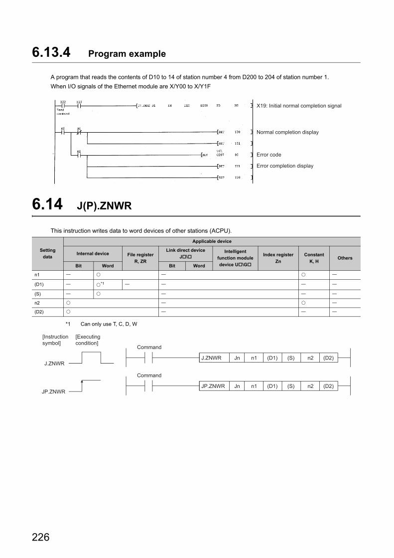
6.13.4 Program example
A program that reads the contents of D10 to 14 of station number 4 from D200 to 204 of station number 1.
When I/O signals of the Ethernet module are X/Y00 to X/Y1F
6.14 J(P).ZNWR
This instruction writes data to word devices of other stations (ACPU).
*1 Can only use T, C, D, W
Setting
data
Applicable device
Internal device File register
R, ZR
Link direct device
J\Intelligent
function module
device U\G
Index register
Zn
Constant
K, HOthers
Bit Word Bit Word
n1
(D1) *1
(S)
n2
(D2)
X19: Initial normal completion signal
Error completion display
Error code
Normal completion display
JP.ZNWRJP.ZNWR
J.ZNWR
(D2)(S)(D1) n2n1
(D2)n2(S)(D1)n1JnJ.ZNWR
Jn
[Executing condition]
[Instruction symbol]
Command
Command
226
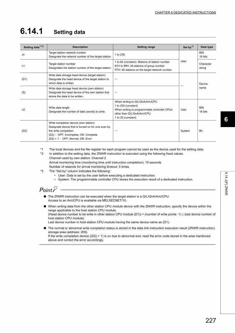
CHAPTER 6 DEDICATED INSTRUCTIONS
6
6.1
4 J(P
).ZN
WR
6.14.1 Setting data
*1 The local devices and the file register for each program cannot be used as the device used for the setting data.*2 In addition to the setting data, the ZNWR instruction is executed using the following fixed values.
Channel used by own station: Channel 2Arrival monitoring time (monitoring time until instruction completion): 10 secondsNumber of resends for arrival monitoring timeout: 5 times
*3 The "Set by" column indicates the following:• User: Data is set by the user before executing a dedicated instruction.• System: The programmable controller CPU stores the execution result of a dedicated instruction.
● The ZNWR instruction can be executed when the target station is a Q/L/QnA/AnUCPU.Access to an AnUCPU is available via MELSECNET/10.
● When writing data from the other station CPU module device with the ZNWR instruction, specify the device within the range applicable to the host station CPU module.(Head device number to be write in other station CPU module (D1)) + (number of write points -1) (last device number of host station CPU module)Last device number in host station CPU module having the same device name as (D1).
● The normal or abnormal write completion status is stored in the data link instruction execution result (ZNWR instruction) storage area (address: 209).If the write completion device ((D2) + 1) is on due to abnormal end, read the error code stored in the area mentioned above and correct the error accordingly.
Setting data*1*2 Description Setting range Set by*3 Data type
JnTarget station network number
Designate the network number of the target station.1 to 239
User
BIN
16 bits
n1Target station number
Designates the station number of the target station.
1 to 64 (constant): Stations of station number
81H to 89H: All stations of group number
FFH: All stations on the target network number
Character
string
(D1)
Write data storage head device (target station)
Designate the head device of the target station to
which data is written.
Device
name
(S)
Write data storage head device (own station)
Designate the head device of the own station that
stores the data to be written.
n2Write data length
Designate the number of data (words) to write.
When writing to Q/L/QnA/AnUCPU
1 to 230 (constant)
When writing to programmable controller CPUs
other than Q/L/QnA/AnUCPU
1 to 32 (constant)
UserBIN
16 bits
(D2)
Write completion device (own station)
Designate device that is turned on for one scan by
the write completion.
(D2) OFF: Incomplete, ON: Complete
(D2) + 1 OFF: Normal, ON: Error
System Bit
227
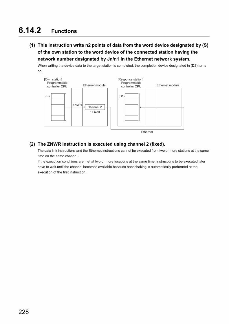
6.14.2 Functions
(1) This instruction write n2 points of data from the word device designated by (S)
of the own station to the word device of the connected station having the
network number designated by Jn/n1 in the Ethernet network system.When writing the device data to the target station is completed, the completion device designated in (D2) turns
on.
(2) The ZNWR instruction is executed using channel 2 (fixed).The data link instructions and the Ethernet instructions cannot be executed from two or more stations at the same
time on the same channel.
If the execution conditions are met at two or more locations at the same time, instructions to be executed later
have to wait until the channel becomes available because handshaking is automatically performed at the
execution of the first instruction.
(S)
Ethernet
(D1)
ZNWR
Programmable controller CPU
Programmable controller CPU
Channel 2
[Own station] [Response station]
Ethernet module Ethernet module
* Fixed
228
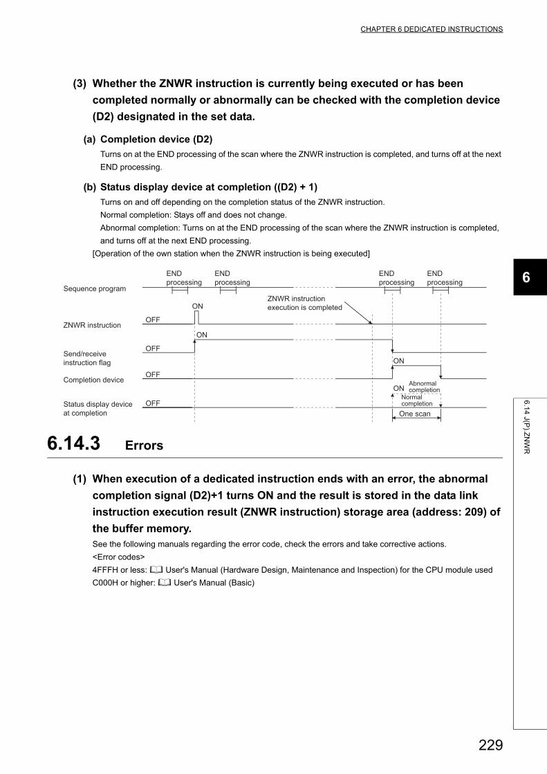
CHAPTER 6 DEDICATED INSTRUCTIONS
6
6.1
4 J(P
).ZN
WR
(3) Whether the ZNWR instruction is currently being executed or has been
completed normally or abnormally can be checked with the completion device
(D2) designated in the set data.
(a) Completion device (D2)
Turns on at the END processing of the scan where the ZNWR instruction is completed, and turns off at the next
END processing.
(b) Status display device at completion ((D2) + 1)
Turns on and off depending on the completion status of the ZNWR instruction.
Normal completion: Stays off and does not change.
Abnormal completion: Turns on at the END processing of the scan where the ZNWR instruction is completed,
and turns off at the next END processing.
[Operation of the own station when the ZNWR instruction is being executed]
6.14.3 Errors
(1) When execution of a dedicated instruction ends with an error, the abnormal
completion signal (D2)+1 turns ON and the result is stored in the data link
instruction execution result (ZNWR instruction) storage area (address: 209) of
the buffer memory.See the following manuals regarding the error code, check the errors and take corrective actions.
<Error codes>
4FFFH or less: User's Manual (Hardware Design, Maintenance and Inspection) for the CPU module used
C000H or higher: User's Manual (Basic)
ON
OFF
OFF
ON
OFF
ON
OFF
ON
One scan
Abnormal completion
END processing
END processing
END processing
END processing
Status display device at completion
Normal completion
Completion device
Send/receive instruction flag
ZNWR instruction execution is completed
ZNWR instruction
Sequence program
229
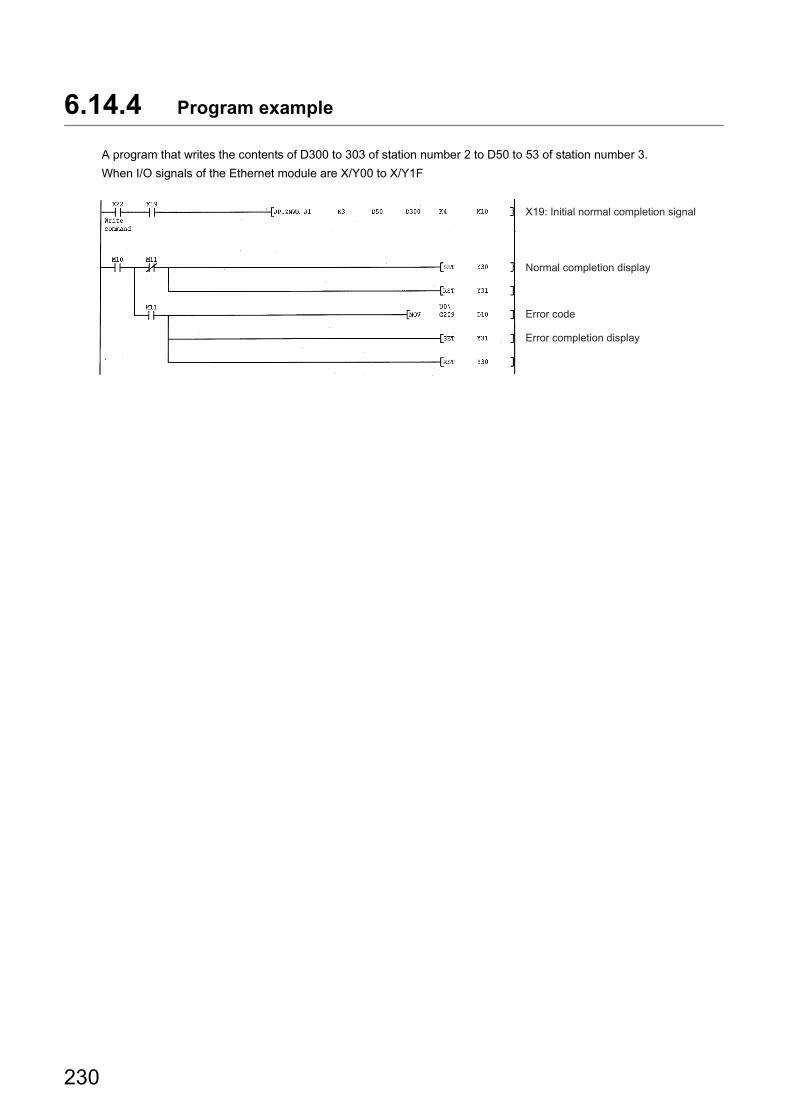
6.14.4 Program example
A program that writes the contents of D300 to 303 of station number 2 to D50 to 53 of station number 3.
When I/O signals of the Ethernet module are X/Y00 to X/Y1F
X19: Initial normal completion signal
Error completion display
Error code
Normal completion display
230
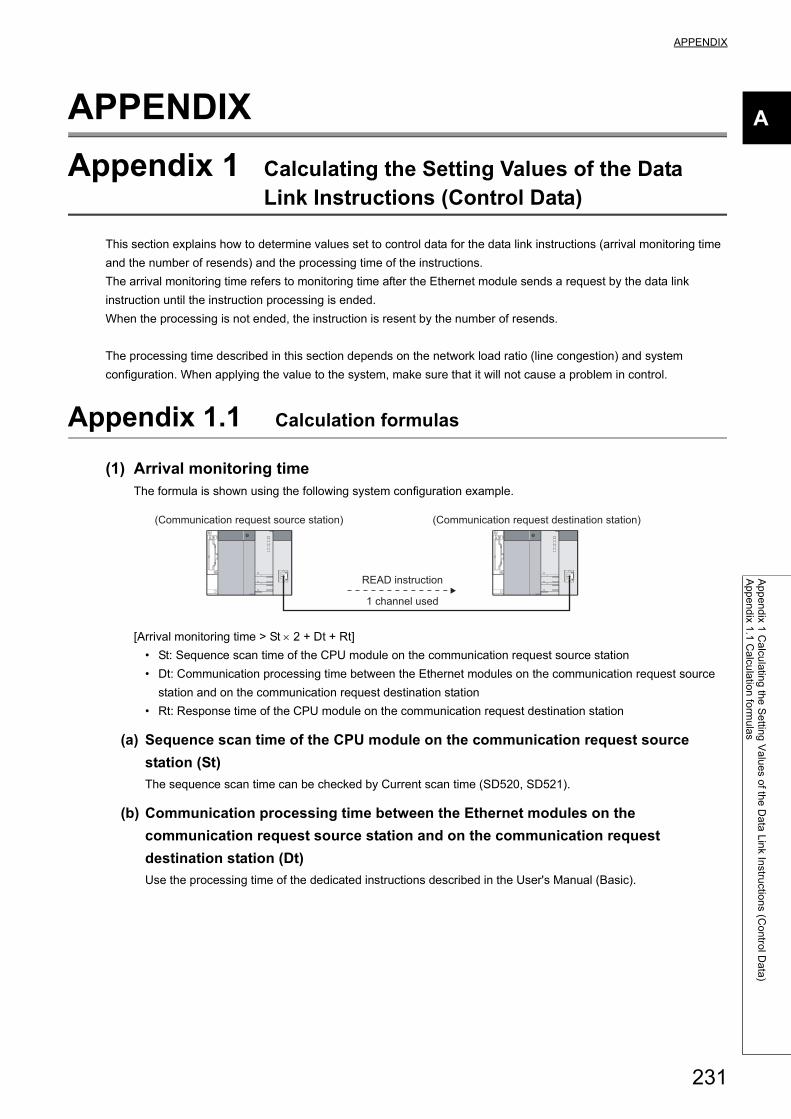
APPENDIX
A
Ap
pe
nd
ix 1 C
alcu
latin
g th
e S
ettin
g V
alu
es o
f the
Da
ta L
ink In
structio
ns (C
on
trol D
ata
)A
pp
en
dix 1
.1 C
alcu
latio
n fo
rmu
las
APPENDIX
Appendix 1 Calculating the Setting Values of the Data Link Instructions (Control Data)
This section explains how to determine values set to control data for the data link instructions (arrival monitoring time
and the number of resends) and the processing time of the instructions.
The arrival monitoring time refers to monitoring time after the Ethernet module sends a request by the data link
instruction until the instruction processing is ended.
When the processing is not ended, the instruction is resent by the number of resends.
The processing time described in this section depends on the network load ratio (line congestion) and system
configuration. When applying the value to the system, make sure that it will not cause a problem in control.
Appendix 1.1 Calculation formulas
(1) Arrival monitoring timeThe formula is shown using the following system configuration example.
[Arrival monitoring time > St 2 + Dt + Rt]
• St: Sequence scan time of the CPU module on the communication request source station
• Dt: Communication processing time between the Ethernet modules on the communication request source
station and on the communication request destination station
• Rt: Response time of the CPU module on the communication request destination station
(a) Sequence scan time of the CPU module on the communication request source
station (St)
The sequence scan time can be checked by Current scan time (SD520, SD521).
(b) Communication processing time between the Ethernet modules on the
communication request source station and on the communication request
destination station (Dt)
Use the processing time of the dedicated instructions described in the User's Manual (Basic).
READ instruction
(Communication request source station) (Communication request destination station)
1 channel used
231
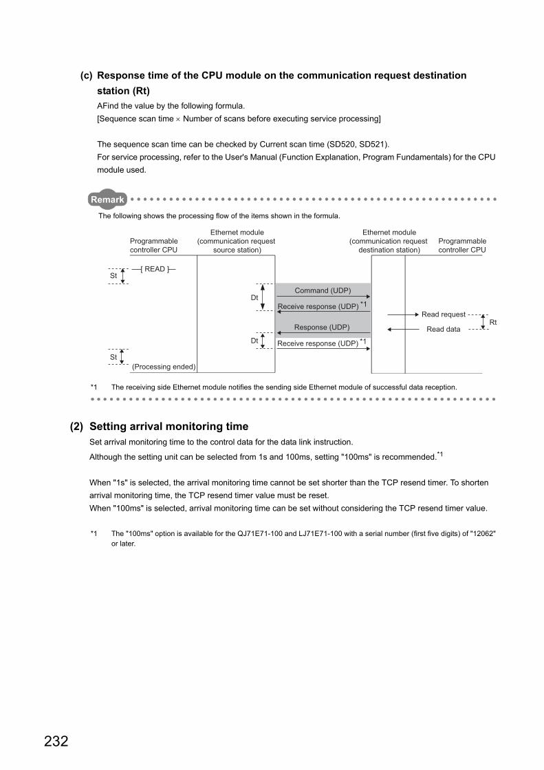
(c) Response time of the CPU module on the communication request destination
station (Rt)
AFind the value by the following formula.
[Sequence scan time Number of scans before executing service processing]
The sequence scan time can be checked by Current scan time (SD520, SD521).
For service processing, refer to the User's Manual (Function Explanation, Program Fundamentals) for the CPU
module used.
Remark
The following shows the processing flow of the items shown in the formula.
*1 The receiving side Ethernet module notifies the sending side Ethernet module of successful data reception.
(2) Setting arrival monitoring timeSet arrival monitoring time to the control data for the data link instruction.
Although the setting unit can be selected from 1s and 100ms, setting "100ms" is recommended.*1
When "1s" is selected, the arrival monitoring time cannot be set shorter than the TCP resend timer. To shorten
arrival monitoring time, the TCP resend timer value must be reset.
When "100ms" is selected, arrival monitoring time can be set without considering the TCP resend timer value.
*1 The "100ms" option is available for the QJ71E71-100 and LJ71E71-100 with a serial number (first five digits) of "12062" or later.
[ READ ]
Dt
Rt
Dt
St
St
Programmable controller CPU
(Processing ended)
Ethernet module(communication request
source station)Programmable controller CPU
Receive response (UDP)
Read request
Read data
*1
*1
Command (UDP)
Receive response (UDP)
Response (UDP)
Ethernet module(communication request
destination station)
232
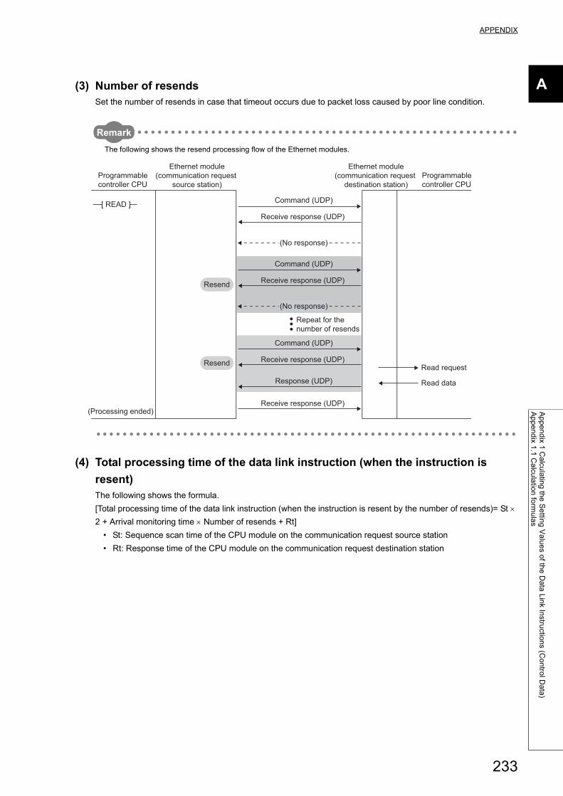
APPENDIX
A
Ap
pe
nd
ix 1 C
alcu
latin
g th
e S
ettin
g V
alu
es o
f the
Da
ta L
ink In
structio
ns (C
on
trol D
ata
)A
pp
en
dix 1
.1 C
alcu
latio
n fo
rmu
las
(3) Number of resendsSet the number of resends in case that timeout occurs due to packet loss caused by poor line condition.
Remark
The following shows the resend processing flow of the Ethernet modules.
(4) Total processing time of the data link instruction (when the instruction is
resent)The following shows the formula.
[Total processing time of the data link instruction (when the instruction is resent by the number of resends)= St
2 + Arrival monitoring time Number of resends + Rt]
• St: Sequence scan time of the CPU module on the communication request source station
• Rt: Response time of the CPU module on the communication request destination station
[ READ ]
(No response)
Programmable controller CPU
(Processing ended)
Ethernet module(communication request
source station)Programmable controller CPU
Command (UDP)
Repeat for the number of resends
Receive response (UDP)
Receive response (UDP)
Read request
Read data
(No response)
Command (UDP)
Receive response (UDP)
Command (UDP)
Receive response (UDP)
Response (UDP)
Ethernet module(communication request
destination station)
Resend
Resend
233
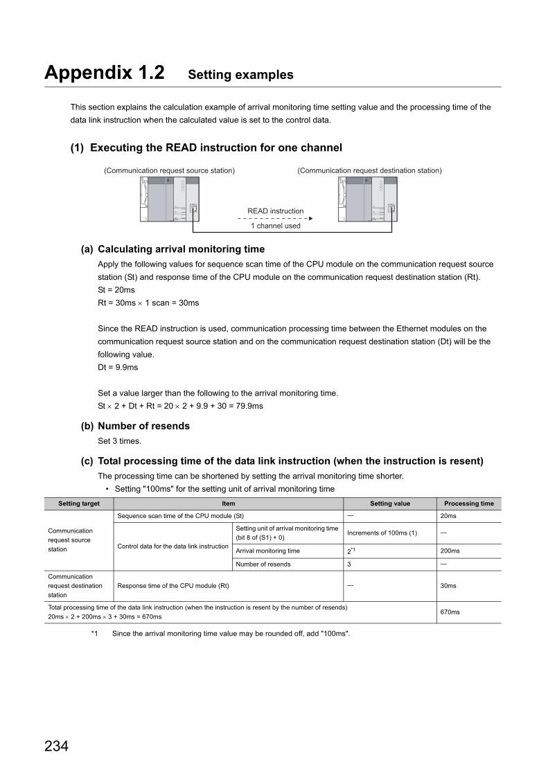
Appendix 1.2 Setting examples
This section explains the calculation example of arrival monitoring time setting value and the processing time of the
data link instruction when the calculated value is set to the control data.
(1) Executing the READ instruction for one channel
(a) Calculating arrival monitoring time
Apply the following values for sequence scan time of the CPU module on the communication request source
station (St) and response time of the CPU module on the communication request destination station (Rt).
St = 20ms
Rt = 30ms 1 scan = 30ms
Since the READ instruction is used, communication processing time between the Ethernet modules on the
communication request source station and on the communication request destination station (Dt) will be the
following value.
Dt = 9.9ms
Set a value larger than the following to the arrival monitoring time.
St 2 + Dt + Rt = 20 2 + 9.9 + 30 = 79.9ms
(b) Number of resends
Set 3 times.
(c) Total processing time of the data link instruction (when the instruction is resent)
The processing time can be shortened by setting the arrival monitoring time shorter.
• Setting "100ms" for the setting unit of arrival monitoring time
*1 Since the arrival monitoring time value may be rounded off, add "100ms".
Setting target Item Setting value Processing time
Communication
request source
station
Sequence scan time of the CPU module (St) 20ms
Control data for the data link instruction
Setting unit of arrival monitoring time
(bit 8 of (S1) + 0)Increments of 100ms (1)
Arrival monitoring time 2*1 200ms
Number of resends 3
Communication
request destination
station
Response time of the CPU module (Rt) 30ms
Total processing time of the data link instruction (when the instruction is resent by the number of resends)
20ms 2 + 200ms 3 + 30ms = 670ms670ms
READ instruction
(Communication request source station) (Communication request destination station)
1 channel used
234
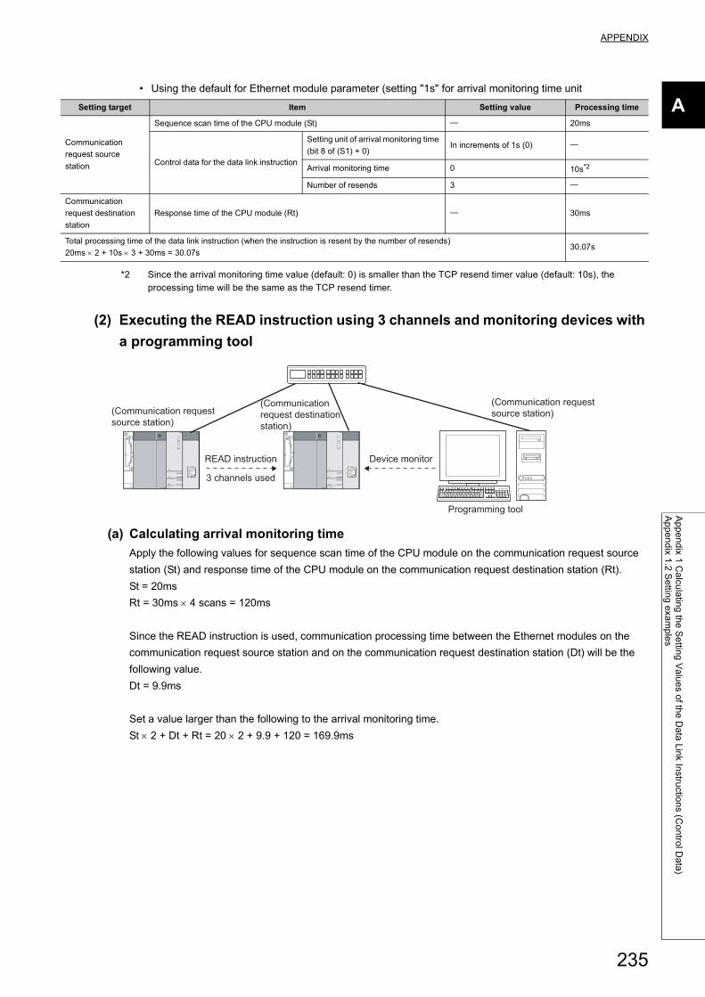
APPENDIX
A
Ap
pe
nd
ix 1 C
alcu
latin
g th
e S
ettin
g V
alu
es o
f the
Da
ta L
ink In
structio
ns (C
on
trol D
ata
)A
pp
en
dix 1
.2 S
ettin
g e
xam
ple
s
• Using the default for Ethernet module parameter (setting "1s" for arrival monitoring time unit
*2 Since the arrival monitoring time value (default: 0) is smaller than the TCP resend timer value (default: 10s), the processing time will be the same as the TCP resend timer.
(2) Executing the READ instruction using 3 channels and monitoring devices with
a programming tool
(a) Calculating arrival monitoring time
Apply the following values for sequence scan time of the CPU module on the communication request source
station (St) and response time of the CPU module on the communication request destination station (Rt).
St = 20ms
Rt = 30ms 4 scans = 120ms
Since the READ instruction is used, communication processing time between the Ethernet modules on the
communication request source station and on the communication request destination station (Dt) will be the
following value.
Dt = 9.9ms
Set a value larger than the following to the arrival monitoring time.
St 2 + Dt + Rt = 20 2 + 9.9 + 120 = 169.9ms
Setting target Item Setting value Processing time
Communication
request source
station
Sequence scan time of the CPU module (St) 20ms
Control data for the data link instruction
Setting unit of arrival monitoring time
(bit 8 of (S1) + 0)In increments of 1s (0)
Arrival monitoring time 0 10s*2
Number of resends 3
Communication
request destination
station
Response time of the CPU module (Rt) 30ms
Total processing time of the data link instruction (when the instruction is resent by the number of resends)
20ms 2 + 10s 3 + 30ms = 30.07s30.07s
READ instruction
(Communication request source station)
(Communication request source station)
(Communication request destination station)
Device monitor
Programming tool
3 channels used
235

In this processing, the READ instruction is executed using 3 channels and device monitor is performed. Therefore, the maximum 4 scans may be required. (30ms 4 scans = 120ms)However, the processing can be performed in one scan by the following setting. (30ms 1 scan = 30ms)
• Time reserved for communication processing (SD315)• (other than the Universal model QCPU, LCPU)
(Example)Arrival monitoring time when service processing is set to 4 times:St 2 + Dt + Rt = 20 2 + 9.9 + 30 = 79.9ms
For details on the setting, refer to the User's Manual (Function Explanation, Program Fundamentals) for the CPU module used.
(b) Number of resends
Set 3 times.
(c) Total processing time of the data link instruction (when the instruction is resent)
The processing time can be shortened by setting the arrival monitoring time shorter.
• Setting "100ms" for the setting unit of arrival monitoring time
*1 Values in parentheses are assumed that service processing is set to 4 times. ( Page 235, Appendix 1.2 (2) (a))*2 Since the arrival monitoring time value may be rounded off, add "100ms".
• Using the default for Ethernet module parameter (setting "1s" for arrival monitoring time unit
*3 Values in parentheses are assumed that service processing is set to 4 times. ( Page 235, Appendix 1.2 (2) (a))*4 Since the arrival monitoring time value (default: 0) is smaller than the TCP resend timer value (default: 10s), the
processing time will be the same as the TCP resend timer.
Setting target Item Setting value Processing time*1
Communication
request source
station
Sequence scan time of the CPU module (St) 20ms
Control data for the data link instruction
Setting unit of arrival monitoring time
(bit 8 of (S1) + 0)Increments of 100ms (1)
Arrival monitoring time 3*2300ms
(200ms)
Number of resends 3
Communication
request destination
station
Response time of the CPU module (Rt) 120ms
(30ms)
Total processing time of the data link instruction (when the instruction is resent by the number of resends)
20ms 2 + 300ms 3 + 120ms = 1060ms
(20ms 2 + 200ms 3 + 30ms = 670ms)
1060ms
(670ms)
Setting target Item Setting value Processing time*3
Communication
request source
station
Sequence scan time of the CPU module (St) 20ms
Control data for the data link instruction
Setting unit of arrival monitoring time
(bit 8 of (S1) + 0)
In increments of 1s
(0)
Arrival monitoring time 0 10s*4
Number of resends 3
Communication
request destination
station
Response time of the CPU module (Rt) 120ms
(30ms)
Total processing time of the data link instruction (when the instruction is resent by the number of resends)
20ms 2 + 10s 3 + 120ms = 30.16s
(20ms 2 + 10s 3 + 30ms = 30.07s)
30.16s
(30.07s)
236
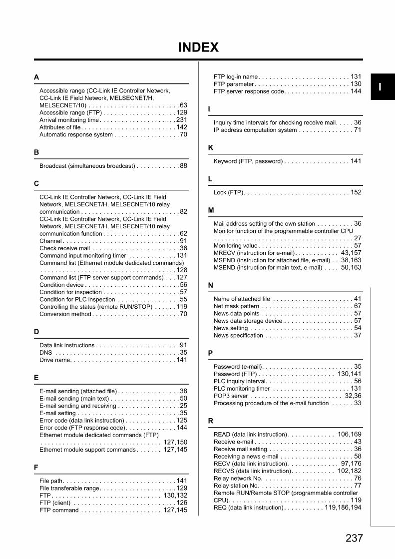
I
4
4
7
8
INDEX
A
Accessible range (CC-Link IE Controller Network, CC-Link IE Field Network, MELSECNET/H, MELSECNET/10) . . . . . . . . . . . . . . . . . . . . . . . . . 63Accessible range (FTP) . . . . . . . . . . . . . . . . . . . . 129Arrival monitoring time. . . . . . . . . . . . . . . . . . . . . 231Attributes of file. . . . . . . . . . . . . . . . . . . . . . . . . . 142Automatic response system . . . . . . . . . . . . . . . . . . 70
B
Broadcast (simultaneous broadcast) . . . . . . . . . . . . 88
C
CC-Link IE Controller Network, CC-Link IE Field Network, MELSECNET/H, MELSECNET/10 relay communication . . . . . . . . . . . . . . . . . . . . . . . . . . . 82CC-Link IE Controller Network, CC-Link IE Field Network, MELSECNET/H, MELSECNET/10 relay communication function . . . . . . . . . . . . . . . . . . . . . 62Channel . . . . . . . . . . . . . . . . . . . . . . . . . . . . . . . . 91Check receive mail . . . . . . . . . . . . . . . . . . . . . . . . 36Command input monitoring timer . . . . . . . . . . . . . 131Command list (Ethernet module dedicated commands). . . . . . . . . . . . . . . . . . . . . . . . . . . . . . . . . . . . . 128Command list (FTP server support commands) . . . 127Condition device . . . . . . . . . . . . . . . . . . . . . . . . . . 56Condition for inspection . . . . . . . . . . . . . . . . . . . . . 57Condition for PLC inspection . . . . . . . . . . . . . . . . . 55Controlling the status (remote RUN/STOP) . . . . . . 119Conversion method . . . . . . . . . . . . . . . . . . . . . . . . 70
D
Data link instructions . . . . . . . . . . . . . . . . . . . . . . . 91DNS . . . . . . . . . . . . . . . . . . . . . . . . . . . . . . . . . . 35Drive name. . . . . . . . . . . . . . . . . . . . . . . . . . . . . 141
E
E-mail sending (attached file) . . . . . . . . . . . . . . . . . 38E-mail sending (main text) . . . . . . . . . . . . . . . . . . . 50E-mail sending and receiving . . . . . . . . . . . . . . . . . 25E-mail setting . . . . . . . . . . . . . . . . . . . . . . . . . . . . 35Error code (data link instruction) . . . . . . . . . . . . . . 125Error code (FTP response code). . . . . . . . . . . . . . 144Ethernet module dedicated commands (FTP). . . . . . . . . . . . . . . . . . . . . . . . . . . . . . . . . 127,150Ethernet module support commands . . . . . . . 127,145
F
File path. . . . . . . . . . . . . . . . . . . . . . . . . . . . . . . 141File transferable range. . . . . . . . . . . . . . . . . . . . . 129FTP . . . . . . . . . . . . . . . . . . . . . . . . . . . . . . 130,132FTP (client) . . . . . . . . . . . . . . . . . . . . . . . . . . . . 126FTP command . . . . . . . . . . . . . . . . . . . . . . 127,145
FTP log-in name. . . . . . . . . . . . . . . . . . . . . . . . . 131FTP parameter . . . . . . . . . . . . . . . . . . . . . . . . . . 130FTP server response code. . . . . . . . . . . . . . . . . . 144
I
Inquiry time intervals for checking receive mail. . . . . 36IP address computation system . . . . . . . . . . . . . . . 71
K
Keyword (FTP, password) . . . . . . . . . . . . . . . . . . 141
L
Lock (FTP). . . . . . . . . . . . . . . . . . . . . . . . . . . . . 152
M
Mail address setting of the own station . . . . . . . . . . 36Monitor function of the programmable controller CPU. . . . . . . . . . . . . . . . . . . . . . . . . . . . . . . . . . . . . . 27Monitoring value . . . . . . . . . . . . . . . . . . . . . . . . . . 57MRECV (instruction for e-mail) . . . . . . . . . . . . 43,157MSEND (instruction for attached file, e-mail) . . 38,163MSEND (instruction for main text, e-mail) . . . . 50,163
N
Name of attached file . . . . . . . . . . . . . . . . . . . . . . 41Net mask pattern . . . . . . . . . . . . . . . . . . . . . . . . . 67News data points . . . . . . . . . . . . . . . . . . . . . . . . . 57News data storage device . . . . . . . . . . . . . . . . . . . 57News setting . . . . . . . . . . . . . . . . . . . . . . . . . . . . 54News specification . . . . . . . . . . . . . . . . . . . . . . . . 37
P
Password (e-mail). . . . . . . . . . . . . . . . . . . . . . . . . 35Password (FTP) . . . . . . . . . . . . . . . . . . . . . 130,141PLC inquiry interval. . . . . . . . . . . . . . . . . . . . . . . . 56PLC monitoring timer . . . . . . . . . . . . . . . . . . . . . 131POP3 server . . . . . . . . . . . . . . . . . . . . . . . . . 32,36Processing procedure of the e-mail function . . . . . . 33
R
READ (data link instruction) . . . . . . . . . . . . . 106,169Receive e-mail . . . . . . . . . . . . . . . . . . . . . . . . . . . 43Receive mail setting . . . . . . . . . . . . . . . . . . . . . . . 36Receiving a news e-mail . . . . . . . . . . . . . . . . . . . . 58RECV (data link instruction) . . . . . . . . . . . . . . 97,176RECVS (data link instruction). . . . . . . . . . . . 102,182Relay network No. . . . . . . . . . . . . . . . . . . . . . . . . 76Relay station No. . . . . . . . . . . . . . . . . . . . . . . . . . 77Remote RUN/Remote STOP (programmable controller CPU). . . . . . . . . . . . . . . . . . . . . . . . . . . . . . . . . 119REQ (data link instruction) . . . . . . . . . . . 119,186,194
237
Routing parameter settings . . . . . . . . . . . . . . . . . . 76
S
SEND (data link instruction) . . . . . . . . . . . . . . 96,197Send mail address setting . . . . . . . . . . . . . . . . . . . 37Send mail setting . . . . . . . . . . . . . . . . . . . . . . . . . 36Simultaneous broadcast (UDP/IP) . . . . . . . . . . . . . 88SMTP server . . . . . . . . . . . . . . . . . . . . . . . . . . 32,36SREAD (data link instruction) . . . . . . . . . . . . 106,205Station No. <-> IP information . . . . . . . . . . . . . . . . 66Station No. <-> IP information system (conversion method) . . . . . . . . . . . . . . . . . . . . . . . . . . . . . . . 67SWRITE (data link instruction). . . . . . . . . . . . 107,210
T
Table exchange system . . . . . . . . . . . . . . . . . . . . 73Target network No.. . . . . . . . . . . . . . . . . . . . . . . . 76
U
Unlock (FTP) . . . . . . . . . . . . . . . . . . . . . . . . 133,152Use-together system . . . . . . . . . . . . . . . . . . . . . . 75
W
WRITE (data link instruction) . . . . . . . . . . . . . 107,215
Z
ZNRD (data link instruction) . . . . . . . . . . . . . 113,223ZNWR (data link instruction) . . . . . . . . . . . . . 114,226
238
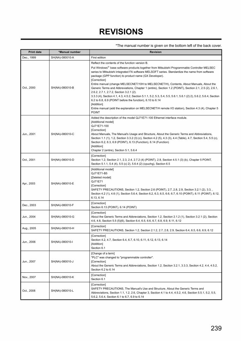
REVISIONS
*The manual number is given on the bottom left of the back cover.
Print date *Manual number Revision
Dec., 1999 SH(NA)-080010-A First edition
Oct., 2000 SH(NA)-080010-B
Reflect the contents of the function version B.
Put Windows base software products together from Mitsubishi Programmable Controller MELSEC
series to Mitsubishi integrated FA software MELSOFT series. Standardize the name from software
package (GPP function) to product name (GX Developer).
[Correction]
Entire manual (change MELSECNET/10H to MELSECNET/H), Contents, About Manuals, About the
Generic Terms and Abbreviations, Chapter 1 (entire), Section 1.2 (POINT), Section 2.1, 2.5 (2), 2.6.1,
2.6.2, 2.7.1, 2.7.2, Section 3.2.1 (2).
3.3.3 (4), Section 4.1, 4.3, 4.5.2, Section 5.1.1, 5.2, 5.3, 5.4, 5.5, 5.6.1, 5.6.1 (2) 2), 5.6.2, 5.6.4, Section
6.2 to 6.8, 6.9 (POINT before the function), 6.10 to 6.14
[Addition]
Entire manual (add the explanation on MELSECNET/H remote I/O station), Section 4.3 (4), Chapter 5
POINT
Jun., 2001 SH(NA)-080010-C
Added the description of the model QJ71E71-100 Ethernet interface module.
[Additional model]
QJ71E71-100
[Correction]
About Manuals, The Manual's Usage and Structure, About the Generic Terms and Abbreviations,
Section 1.1 (1), 1.2, Section 3.3.2 (3) (c), Section 4.2 (5), 4.3 (3), 4.4 (Table), 4.7, Section 5.4, 5.5 (c),
Section 6.2, 6.3, 6.9 (POINT), 6.13 (Function), 6.14 (Function)
[Addition]
Chapter 2 (entire), Section 5.1, 5.6.4
Oct., 2001 SH(NA)-080010-D
[Correction]
Section 1.2, Section 2.1, 2.3, 2.4, 2.7.2 (4) (POINT), 2.8, Section 4.5.1 (3) (b), Chapter 5 POINT,
Section 5.1.1, 5.4 (4), 5.5 (c) 2), 5.6.4 (2) (cpuchg), Section 6.5
Apr., 2003 SH(NA)-080010-E
[Additional model]
QJ71E71-B5
[Deleted model]
QJ71E71
[Correction]
SAFETY PRECAUTIONS, Section 1.2, Section 2.6 (POINT), 2.7, 2.8, 2.9, Section 3.2.1 (2), 3.3, ,
Section 4.2 (1), 4.6 (1), Section 5.6.4, Section 6.2, 6.3, 6.5, 6.6, 6.7, 6.10 (POINT), 6.11 (POINT), 6.12,
6.13, 6.14
Dec., 2003 SH(NA)-080010-F[Correction]
Section 6.13 (POINT), 6.14 (POINT)
Jun., 2004 SH(NA)-080010-G
[Correction]
About the Generic Terms and Abbreviations, Section 1.2, Section 2.1.2 (1), Section 3.2.1 (2), Section
4.6, 4.8, Section 5.5 (5)(6), Section 6.4, 6.5, 6.6, 6.7, 6.8, 6.9, 6.11, 6.12
Aug., 2005 SH(NA)-080010-H[Correction]
SAFETY PRECAUTIONS, Section 1.2, Section 2.1.2, 2.7, 2.8, 2.9, Section 6.4, 6.5, 6.6, 6.9, 6.12
Jun., 2006 SH(NA)-080010-I
[Correction]
Section 4.2, 4.7, Section 6.4, 6.7, 6.10, 6.11, 6.12, 6.13, 6.14
[Addition]
Section 6.1
Jun., 2007 SH(NA)-080010-J
[Change of a term]
"PLC" was changed to "programmable controller".
[Correction]
About the Generic Terms and Abbreviations, Section 1.2, Section 3.2.1, 3.3.3, Section 4.2, 4.4, 4.5.2,
Section 6.2 to 6.14
Nov., 2007 SH(NA)-080010-K[Correction]
Section 6.1
Oct., 2008 SH(NA)-080010-L
[Correction]
SAFETY PRECAUTIONS, The Manual's Use and Structure, About the Generic Terms and
Abbreviations, Section 1.1, 1.2, 2.6, Chapter 3, Section 4.1 to 4.4, 4.5.2, 4.6, Section 5.5.1, 5.2, 5.5,
5.6.2, 5.6.4, Section 6.1 to 6.7, 6.9 to 6.14
239
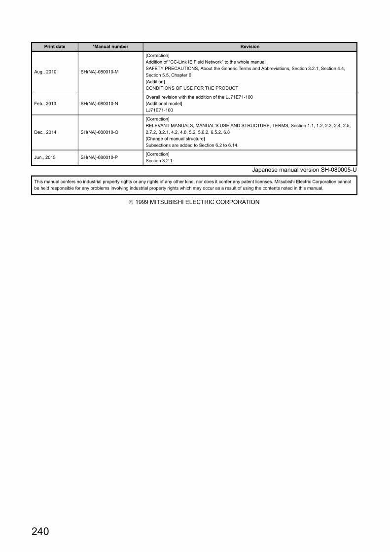
Japanese manual version SH-080005-U
1999 MITSUBISHI ELECTRIC CORPORATION
Aug., 2010 SH(NA)-080010-M
[Correction]
Addition of "CC-Link IE Field Network" to the whole manual
SAFETY PRECAUTIONS, About the Generic Terms and Abbreviations, Section 3.2.1, Section 4.4,
Section 5.5, Chapter 6
[Addition]
CONDITIONS OF USE FOR THE PRODUCT
Feb., 2013 SH(NA)-080010-N
Overall revision with the addition of the LJ71E71-100
[Additional model]
LJ71E71-100
Dec., 2014 SH(NA)-080010-O
[Correction]
RELEVANT MANUALS, MANUAL'S USE AND STRUCTURE, TERMS, Section 1.1, 1.2, 2.3, 2.4, 2.5,
2.7.2, 3.2.1, 4.2, 4.8, 5.2, 5.6.2, 6.5.2, 6.8
[Change of manual structure]
Subsections are added to Section 6.2 to 6.14.
Jun., 2015 SH(NA)-080010-P[Correction]
Section 3.2.1
This manual confers no industrial property rights or any rights of any other kind, nor does it confer any patent licenses. Mitsubishi Electric Corporation cannot
be held responsible for any problems involving industrial property rights which may occur as a result of using the contents noted in this manual.
Print date *Manual number Revision
240
241
WARRANTY
Please confirm the following product warranty details before using this product.
1. Gratis Warranty Term and Gratis Warranty RangeIf any faults or defects (hereinafter "Failure") found to be the responsibility of Mitsubishi occurs during use of the product within the gratis warranty term, the product shall be repaired at no cost via the sales representative or Mitsubishi Service Company.However, if repairs are required onsite at domestic or overseas location, expenses to send an engineer will be solely at the customer's discretion. Mitsubishi shall not be held responsible for any re-commissioning, maintenance, or testing on-site that involves replacement of the failed module.[Gratis Warranty Term]The gratis warranty term of the product shall be for one year after the date of purchase or delivery to a designated place.Note that after manufacture and shipment from Mitsubishi, the maximum distribution period shall be six (6) months, and the longest gratis warranty term after manufacturing shall be eighteen (18) months. The gratis warranty term of repair parts shall not exceed the gratis warranty term before repairs.[Gratis Warranty Range](1) The range shall be limited to normal use within the usage state, usage methods and usage environment, etc., which
follow the conditions and precautions, etc., given in the instruction manual, user's manual and caution labels on the product.
(2) Even within the gratis warranty term, repairs shall be charged for in the following cases.1. Failure occurring from inappropriate storage or handling, carelessness or negligence by the user. Failure caused
by the user's hardware or software design.2. Failure caused by unapproved modifications, etc., to the product by the user.3. When the Mitsubishi product is assembled into a user's device, Failure that could have been avoided if functions
or structures, judged as necessary in the legal safety measures the user's device is subject to or as necessary by industry standards, had been provided.
4. Failure that could have been avoided if consumable parts (battery, backlight, fuse, etc.) designated in the instruction manual had been correctly serviced or replaced.
5. Failure caused by external irresistible forces such as fires or abnormal voltages, and Failure caused by force majeure such as earthquakes, lightning, wind and water damage.
6. Failure caused by reasons unpredictable by scientific technology standards at time of shipment from Mitsubishi.7. Any other failure found not to be the responsibility of Mitsubishi or that admitted not to be so by the user.
2. Onerous repair term after discontinuation of production(1) Mitsubishi shall accept onerous product repairs for seven (7) years after production of the product is discontinued.
Discontinuation of production shall be notified with Mitsubishi Technical Bulletins, etc.(2) Product supply (including repair parts) is not available after production is discontinued.
3. Overseas serviceOverseas, repairs shall be accepted by Mitsubishi's local overseas FA Center. Note that the repair conditions at each FA Center may differ.
4. Exclusion of loss in opportunity and secondary loss from warranty liabilityRegardless of the gratis warranty term, Mitsubishi shall not be liable for compensation of damages caused by any cause found not to be the responsibility of Mitsubishi, loss in opportunity, lost profits incurred to the user by Failures of Mitsubishi products, special damages and secondary damages whether foreseeable or not, compensation for accidents, and compensation for damages to products other than Mitsubishi products, replacement by the user, maintenance of on-site equipment, start-up test run and other tasks.
5. Changes in product specificationsThe specifications given in the catalogs, manuals or technical documents are subject to change without prior notice.
242
TRADEMARKS
Microsoft, Windows, Windows Vista, Windows NT, Windows XP, Windows Server, Visio, Excel, PowerPoint, Visual Basic,
Visual C++, and Access are either registered trademarks or trademarks of Microsoft Corporation in the United States,
Japan, and other countries.
Intel, Pentium, and Celeron are either registered trademarks or trademarks of Intel Corporation in the United States and
other countries.
Ethernet is a trademark of Xerox Corp.
The SD and SDHC logos are either registered trademarks or trademarks of SD-3C, LLC.
All other company names and product names used in this manual are either trademarks or registered trademarks of their
respective companies.
SH(NA)-080010-P


SH(NA)-080010-P(1506)MEE
MODEL: QJ71E71-U-OU-E
MODEL CODE: 13JL89
Specifications subject to change without notice.
When exported from Japan, this manual does not require application to theMinistry of Economy, Trade and Industry for service transaction permission.
HEAD OFFICE : TOKYO BUILDING, 2-7-3 MARUNOUCHI, CHIYODA-KU, TOKYO 100-8310, JAPANNAGOYA WORKS : 1-14 , YADA-MINAMI 5-CHOME , HIGASHI-KU, NAGOYA , JAPAN


![MELSEC-Q/L/QnA Programming Manual (SFC) · PDF MELSEC-L CPU Module User's Manual (Function Explanation, Program Fundamentals) [SH-080889ENG] Describes the functions required for programming,](https://img.pdfslide.net/doc/110x75/5fd45d753158732c757105e3/melsec-qlqna-programming-manual-sfc-pdf-melsec-l-cpu-module-users-manual-function.jpg)


![MELSEC-Q/L Programming Manual (MELSAP-L) · MELSEC-L CPU Module User's Manual (Function Explanation, Program Fundamentals) [SH-080889ENG] Describes the functions required for programming,](https://img.pdfslide.net/doc/110x75/61086a4fcf15164b6030f2d4/melsec-ql-programming-manual-melsap-l-melsec-l-cpu-module-users-manual-function.jpg)