Embed Size (px)
Citation preview
vol.01 Vertical Form, Fill & Seal
1Film Feed Roller Axis
Tension Control Coil Spring Lever(g)
Pull the plastic materialfrom the stock.
Plastic material issent to the feeder.
The film stock is formed by heat.
The film side is formed.
Seals and cutsthe plastic film bottom.
The packed food issent to the next process.
Vertical Thermal Heat Sealer(c)
Applications suitable
for this machine operation :
•Food/Beverage bag filling
•Pouch packing
•Powder filling
GOT
5
1A B
20
15
10
5
1A B
30
25
20
15
10
5
1A B
CON0
30
25
20
15
10
5
1A BPULL
POWERQ64PN
QX40QY40P
Q06UDEHCPU
QD77MS16 QY40PQX40
Q64DAN
Q64DAN
RUN
ERR.
AX
QD77MS16AX3AX4
AX1AX2
QD77MS16
(MCCB) (MC)
Conveyor Axis 5
Sealing & Cutting Axis 4
Film Index Axis 2 3,
SERVO AMPLIFIERS & MOTORS
Application
System Example
MELSERVO-J4 Solutions For your all production needs
(b)
2 3,
(c)
(e)
(d)
(c)
(f )
(b)
(a)
5
(i)
Control Flow
1 Film Feed Roller Axis2 Film Index Axis3 Film Index Axis
4 Sealing & Cutting Axis5 Conveyor Axis
(f) Proximity Safety Sensor(g) Tension Control Coil Spring Lever(h) Low Roll Detection Sensor(i) Product Present Sensor
(a) Registration Mark Detection Sensor(b) Feeder(c) Vertical Thermal Heat Sealer(d) Film Index Drives(e) Sealing & Cutting Arms
Simple MotionPLC CPUAnalog output module
QD77MS16Q06UDEHCPUQ64DAN
:::
Servo motorI/O module
HG-KR,HG-SRQX40,QY40P
Servo amplifierGOTMain base unit
MR-J4W3-BGOT1000 seriesQ35DB
:::
::
Fill withthe food.
SystemConfiguration
Settings
Stabilizing the packing quality
Synchronous Control Cam Control Safety Functions
Step1 Step2 Step3 Step4
Parameter Settingfor Synchronous
ControlCam Data Creation
Creation of SequenceProgram
and Positioning Data
Issue1
Shorter tact timewithout increasing shockto the machine.
Issue2 A reliable Safety system
Issue3
S
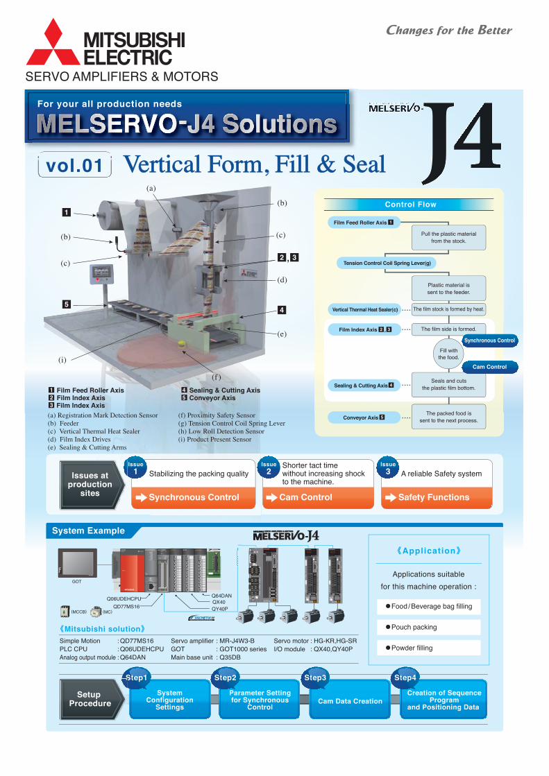
Setup Procedure
Issues atproduction
sites
Synchronous Control
Cam Control
1
4
Mitsubishi solution

Offering theBest Solution
Film index axes Film index axes
Sealing &cutting axis
Sealing &cutting axis
Food
Sealing &cutting axis
Plastic material
Conveyor
Film Index axesCam pattern of the film index axes
The 3-axis synchronization(One sealing & cutting axis, two film index axes)
Operation detail
MR-J4-10B
INPUT
P3
P4
P+C
D
3
8
CN
CN
CN
CN
CN
CN
CN
CN
5
1A
1B
2
2L
4
U
V
WCHARGE
CNP3
CNP2
CNP1
SER
100VAC
OPEN
L11
L21
L1
L2
L3
N-
Smooth waveform
Shut-off by STO function
Sealing &Cutting axis
Film index axesFilm index axesFilm index axes
:XXXXXXXXX
High-quality production is achieved by improving the process accuracy with the 3-axis synchronous control (One sealing & cutting
axis, two film index axes). Eliminating an interlock also enables shorter tact time.
High Quality Production & Shorter Tact TimeSynchronous Control
Possible to create the smooth
pattern with the cam control.
Easily executes the cam control
with the Simple Motion modules.
Food is inserted into the film,being sent by the film index axes. Seal and cut the film.
Cam control enables the smooth sending and stopping of the film material.
Thus high-speed operation and the shorter tact time are achieved.
Smooth Sending & Stopping of the Film MaterialCam Control
Compatible with Safety FunctionsIEC/EN 61800-5-2 as Standard
SafetyFunctions
MR-J4-B series servo amplifiers have integrated
STO (Safe Torque Off) function.
The machine can stop safely without turning off
the main circuit power supply, cutting out the time
for restart.
Cam axis length per cycle
Cam
str
oke
amou
nt
Solution
1
Solution
2
Solution
3
Stopsmotor
Shut-off
MR-J4-B
Servo motor
Magnetic contactorfor preventingunexpected start isno longer required.
Molded casecircuit breaker (MCCB)
Safetyrelay circuit
Magneticcontactor (MC)for servo alarm
Proximitysafety sensor
ProximityProximitysafety sensorsafety sensorProximitysafety sensor
Setup procedure
Set the servo amplifiers andvirtual servo amplifiers.
Step1
System ConfigurationSettings
Set the axis-2 synchronousparameter for the axis-9virtual servo amplifier.
Step2
Parameter Settingsfor SynchronousControl
Create the cam data for the filmindex axes and the sealing &cutting axis.
Step3
Cam Data Creation
Create a program that startsthe synchronous control of thethree axes (1 to 3) and thepositioning operationof the axis 9.
Step4
Creation of Sequence
Program and
Positioning Data
Synchronous control starts just by turning ON the bit of the axis.
Operation starts from the positioning data No.1 by starting the axis of virtual servo amplifier.
Axis 9 Positioning data
PLC CPU
Simple Motion Module
You can create a program just by setting data at the assistant screen.
Control flow
Double click
Virtual servo amplifier axis
Servo amplifier axis
Double click
Click
Servo type
Axis No.
Display the cam data created.
Right click, and select "Add New Data"
Double click
Cam data can be changed by dragging the waveform.
Various curves such as constant acceleration and cycloid can be selected as the cam curves.
Double click
Obviousconfiguration
Set only
what you need.
Flexible campattern setting
Easy program
start
Axis 1, 2, 3 Synchronouscontrol start
Positioning data No.1
Program start
Start device reset
System Setting Amplifier Setting
Synchronous control parameter
Cam data Cam data list
Man, mach ine and env i ronmen t in pe r fec t ha rmony S o l u t i o n
Time
Settlingtime Settling
time
Time
:Command :Actual operation
Operation is unstable. Operation is not followingthe command.
Before After
Simple vibrationsuppression control andadjustable robust filter
A-axis motor
B-axis motor
C-axis motor
Driving power energy
Regenerative energy
MR-J4W3-222B
INPUT
3
8
CN
CN
CN
CN
CN
CN
CN
5
1A
1B
2C
CN
2B
CN2A
4
U
V
A
CHARGE
CNP3
BCNP3
CCNP3
CNP1
CNP2
SER:XXXXXXXXX
200V AC
U
V
OPEN
L1
L2
L3
U
V
MR-J4-10B
INPUT
P3
P4
P+CD
3
8
CN
CN
CN
CN
CN
CN
CN
CN
5
1A
1B
2
2L
4
U
V
WCHARGE
CNP3
CNP2
CNP1
SER
100VAC
OPEN
L11
L21
L1
L2L3
N-
MR-J4-10B
INPUT
P3
P4
P+CD
3
8
CN
CN
CN
CN
CN
CN
CN
CN
5
1A
1B
2
2L
4
U
V
WCHARGE
CNP3
CNP2
CNP1
SER
100VAC
OPEN
L11
L21
L1
L2L3
N-
MR-J4-10B
INPUT
P3
P4
P+CD
3
8
CN
CN
CN
CN
CN
CN
CN
CN
5
1A
1B
2
2L
4
U
V
WCHARGE
CNP3
CNP2
CNP1
SER XXXXXXXXX
100VAC
OPEN
L11
L21
L1
L2L3
N-
MR-J4W3-B(3-axis type)×1unit
Controller
MCCB
MC
MCCB
MC
MCCB
MC
SSCNETIII cable
Main circuit power supply
Magnetic contactor connection
Magnetic contactor control
Encoder
Motor power input
×3
×3
Control circuit power supply ×3
×3
×3
×3
×3
Total 21
Controller
MCCB
MC
[Number of wirings]
SSCNETIII cable
Main circuit power supply
Control circuit power supply
Magnetic contactor connection
Magnetic contactor control
Encoder
Motor power input
×1
×1
×1
×1
×1
×3
×3
Total 11
[Number of wirings]
MR-J4-B×3units
Q06UDHCPU
PULL
POWERQ64PNQJ71E71-100 Q64AD Q64ADQX42
STOP
CN1
CN2
RUN
SW
1 2
Q173DSCPU
EMI
PE
RIP
HE
RA
L I/F
EX
T . I
/F
PULL
Q06UDHCPU
PULL
POWERQ64PNQJ71E71-100 Q64AD Q64ADQX42
STOP
CN1
CN2
RUN
SW
1 2
Q173DSCPU
EMI
PE
RIP
HE
RA
L I/F
EX
T . I
/F
PULL
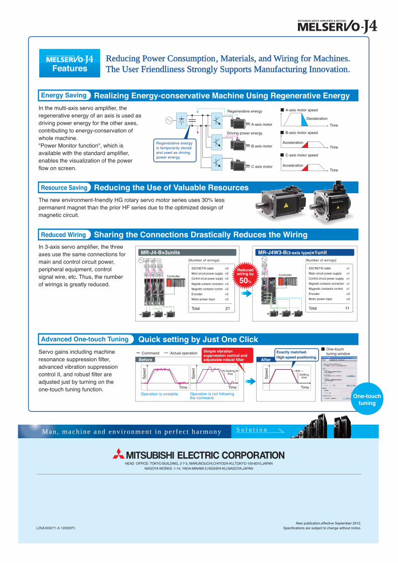
Regenerative energy is temporarily stored and used as driving power energy.
Spe
ed
Spe
ed
Spe
ed
Time
One-touchtuning window
XXXXXXXXX XXXXXXXXX
Deceleration
Time
AccelerationTime
AccelerationTime
A-axis motor speed
B-axis motor speed
C-axis motor speed
In the multi-axis servo amplifier, theregenerative energy of an axis is used asdriving power energy for the other axes,contributing to energy-conservation ofwhole machine."Power Monitor function", which is available with the standard amplifier, enables the visualization of the power flow on screen.
In 3-axis servo amplifier, the three axes use the same connections for main and control circuit power, peripheral equipment, control signal wire, etc. Thus, the number of wirings is greatly reduced.
Servo gains including machine resonance suppression filter, advanced vibration suppression control II, and robust filter areadjusted just by turning on the one-touch tuning function.
The new environment-friendly HG rotary servo motor series uses 30% less permanent magnet than the prior HF series due to the optimized design of magnetic circuit.
Reducing Power ConsumptioReducing Power Consumption, Materials, and Wiring for Machine, Materials, and Wiring for Machines.The User Friendliness Strongly Supports Manufacturing InnovatioThe User Friendliness Strongly Supports Manufacturing Innovation.
One-touchtuning
Reducedwiring by
50%
Realizing Energy-conservative Machine Using Regenerative Energy
Reducing the Use of Valuable Resources
Quick setting by Just One Click
Sharing the Connections Drastically Reduces the Wiring
Features
Energy Saving
Resource Saving
Advanced One-touch Tuning
Reduced Wiring
Exactly matched.High-speed positioning.
HEAD OFFICE: TOKYO BUILDING, 2-7-3, MARUNOUCHI,CHIYODA-KU,TOKYO 100-8310,JAPAN
NAGOYA WORKS: 1-14, YADA-MINAMI 5,HIGASHI-KU,NAGOYA,JAPAN
New publication,effective September 2012.Specifications are subject to change without notice.L(NA)03071-A 1209(IP)