Embed Size (px)
Citation preview

7/27/2019 Membrane Filters_Dairy Processing Hand Book
http://slidepdf.com/reader/full/membrane-filtersdairy-processing-hand-book 1/10
Dairy Processing Handbook/Chapter 6.4 131
Membrane filters
Membrane technology is a proven separation method used on the molecular and ionic levels. Since the beginning of the 1970s, thistechnique has been adapted for the dairy industry.
DefinitionsDefinitions of some frequently used expressions :Feed = the solution to be concentrated or fractionated.Flux = the rate of extraction of permeate measured in
litres per square meter of membrane surface areaper hour (l/m2 /h)
Membrane fouling = deposition and accumulation of feedcomponents on the membrane surface and/orwithin the pores of the membrane. Causes anirreversible flux decline during processing
Permeate = the filtrate, the liquid passing through themembrane
Retentate = the concentrate, the retained liquidConcentration factor = the volume reduction achieved by
concentration, i.e. the ratio of initial volume of feed to the final volume of concentrate/retentate
Diafiltration = a design to obtain better purification. Water isadded to the feed during membrane filtrationwith the purpose to wash out low molecfular feedcomponents which will pass through themembranes, basically lactose and minerals.
Membrane technology In the dairy industry, membrane technology is principally associated with• Reverse Osmosis (RO)
– concentration of solutions by removal of water• Nanofiltration (NF)
– concentration of organic components by removal of part of monovalentions like sodium and chlorine (partial demineralisation)
• Ultrafiltration (UF)– concentration of large and macro molecules, for example proteins
• Microfiltration (MF)– removal of bacteria, separation of macro molecules
The spectrum of application of membrane separation processes in the dairyindustry is shown in Figure 6.4.1.
All the above techniques feature pressure driven membrane filtration
processes, in which the feed solution is forced through the membraneunder pressure. The membranes are categorised by their NaCl retention(RO and NF) molecular weight cut-off (NF and UF), or nominal pore-size

7/27/2019 Membrane Filters_Dairy Processing Hand Book
http://slidepdf.com/reader/full/membrane-filtersdairy-processing-hand-book 2/10
Dairy Processing Handbook/Chapter 6.4132
(MF). The cut-off is, supposedly the molecular weight of the smallestmolecule that will not pass through the membrane. However, owing tovarious interactions, a membrane cannot be selected purely on the basis of its NaCl retention, molecular weight cut-off or nominal pore-size.
It should be mentioned that traditional or conventional filtration, istypically used for separation of suspended particles larger than 10 µm, while membrane filtration separates substances of molecular sizes less than10 µm. Traditional filtration is performed in a dead-end mode, whilemembrane filtration is performed in both dead-end and cross-flow mode.
Fig. 6.4.1 Spectrum of application of membrane separation processes in the dairy industry.
The basic difference between conventional filtration and cross-flowmembrane filtration is illustrated in Figure 6.4.2.
Several differences can be noted between conventional and membranefiltration.• Conventional filters are thick with open structures.
Filter material is typically paper.Gravity is the main force affecting particle separation. Pressure may beapplied only to accelerate the process. The flow of feed is perpendicular to the filter medium, and filtration can be conducted in open systems.
• Membrane filters are thin and of fairly controlled pore size.Filter material is polymers and ceramics, nowadays more rarely celluloseacetate.In membrane filtration, the use of a pressure difference across the
membrane, a trans membrane pressure, TMP, is essential as driving forcefor separation and in cross-flow or tangential membrane filtration a flowdesign is followed. The feed solution runs parallel to the membrane surface
Fig. 6.4.2 Basic differences between conventional dead-end filtration and cross-flow membrane filtration.
Filter
Feed flow
Precipitate
Filtrate
Feed flowConcentrate(retentate)
Permeate(filtrate)
Polarisationeffect
Membrane
Particle size, µm 0,0001 0,001 0,01 0,1 1,0 10 100
Molecular weight, D 100 1 000 10 000 100 000 500 000
Particle characteristic Ionic Molecular Macro-molecular Cellular + micro-particulate
Ions Whey proteins Fat globules Yeast, moulds
Salts Casein micelles Bacteria
Lactose/derivate Vitamins Whey protein aggregates, cheese fines
RO UF Traditional filtration
NF MFSeparation
process
Milk systemcomponents
7/27/2019 Membrane Filters_Dairy Processing Hand Book
http://slidepdf.com/reader/full/membrane-filtersdairy-processing-hand-book 3/10
Dairy Processing Handbook/Chapter 6.4 133
and the permeate flows perpendicular to the membrane surface. Thefiltration must be carried out in a closed system.
Principles of membrane separation The membrane separation techniques utilised in the dairy industry servedifferent purposes:
RO – used for dehydration of whey, UF permeate and condensate.NF – used when partial desalination of whey, UF permeate or
retentate is required.UF – typically used for concentration of milk proteins in milk and whey
and for protein standardisation of milk intended for cheese, yoghurtand some other products. It is also used for clarification of fruit-and berry-juices.
MF – basically used for reduction of bacteria in skim milk, whey andbrine, but also for defatting whey intended for whey proteinconcentrate (WPC) and for protein fractionation.
The general flow patterns of the various membrane separation systems areillustrated in Figure 6.4.3.
Fig 6.4.3 Principles of membrane
filtration.
10-4 – 10-3
10-3 – 10-2
10-2 – 10-1
10-1 – 10 1
30 – 60
20 – 40
1 – 10
< 1
Reverse Osmosis (RO)
Pressure Bar Membrane pore size µm
Nanofiltration (NF)
Ultrafiltration (UF)
Microfiltration (MF)
Bacteria, fatProteinsLactose
Minerals (salts)Water
Feed
Retentate(concentrate)
Permeate(filtrate)

7/27/2019 Membrane Filters_Dairy Processing Hand Book
http://slidepdf.com/reader/full/membrane-filtersdairy-processing-hand-book 4/10
Dairy Processing Handbook/Chapter 6.4134
Filtration modules The filtration modules used may be of different configurations.
Design Typical application
Plate and frame UF, RO Tubular, based on polymers UF, RO Tubular, based on ceramics MF, UF
Spiral-wound RO, NF, UFHollow-fibre UF
Plate and frame design These systems consist of membranes sandwiched between membranesupport plates, which are arranged in stacks, similar to ordinary plate heatexchangers. The feed material is forced through very narrow channels thatmay be configured for parallel flow or as a combination of parallel and serialchannels. A typical design is shown in Figure 6.4.4.
A module is usually divided into sections, in each of which the flow bet-ween pairs of membranes is in parallel. The sections are separated by aspecial membrane support plate in which one hole is closed with a stopdisc to reverse the direction of flow, giving serial flow between successive
sections. Modules are available in various sizes.Membrane material: typical polymers.
Tubular design – polymers The system made by Paterson and Candy International Ltd, PCI, is anexample of tubular systems used in the dairy industry.
The PCI module for UF is illustrated in Figure 6.4.5. The module has 18 x12,5 mm perforated stainless steel tubes assembled in a shell-and-tube-like construction. All 18 tubes are connected in series. A replaceablemembrane insert tube is fitted inside each of the perforated stainless
steel pressure support tubes. Permeate is collected on theoutside of the tube bundle in the stainless steel shroud. Themodule can readily be converted from UF to RO.
Tubular design – ceramic A tubular concept with ceramic membranes is steadily gainingground in the dairy industry, especially in systems for reductionof bacteria in milk, whey, WPC and brine.
The filter element (Figure 6.4.6) is a ceramic filtermanufactured by the company Pall Exekia.
The thin walls of the channels are made of fine-grainedceramic and constitute the membrane. The support material is coarse-grained ceramic.
In MF for bacteria removal, the system is fed with skim milk, becausewith whole milk, the fat would also be concentrated, which
is undesirable in applications for bacteria reduction.Most of the feed (about 95 %) passes through themembrane as permeate, in this case bacteria-
reduced skim milk. The retentate, some 5 % of the feed, is bacteria-rich skim milk.
The filter elements (1, 7, 19 or 37 inparallel) are installed in a module. Figure
6.4.7 shows a module with 19 filterelements, one of which is exposed tothe left of the module. For industrialpurposes, two modules are puttogether in series, forming a filterloop together with one retentate
circulation pump and one permeatecirculation pump (Figure 6.4.10).Depending on the required
Fig. 6.4.4 Example of a plate and frame
system (DDS) for UF.
Permeateoutlet
Feed
Retentate
Feed
Retentate
Permeate
Membrane Support plateand permeatecollector
Retentate
Permeate
Membrane
Retentate
Feed
Stainlesssteel shroud
Perforated steelsupporting tubes
Fig. 6.4.5 Example of a tubular module
to be integrated into a UF (or RO) sys-tem (PCI).
Fig 6.4.7 The filter elements,1, 7 or 19(shown) in parallel, are installed in a
stainless steel module.
Fig.6.4.6 Cross-flow filtration in a
multichannel element (19 channels).
Channel
Retentate
Support
Support
Membrane
Permeate
7/27/2019 Membrane Filters_Dairy Processing Hand Book
http://slidepdf.com/reader/full/membrane-filtersdairy-processing-hand-book 5/10
Dairy Processing Handbook/Chapter 6.4 135
Fig. 6.4.10 An industrial membrane filter loop consists of:
– two filter modules connected in series – one retentate circulation pump
– one permeate circulation pump
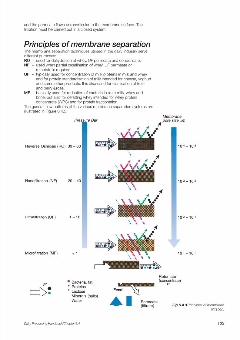
Fig 6.4.9 Pressure drop at the Uniform
Transmembrane Pressure system.
Fig 6.4.8 Pressure drop during conventional
cross-flow microfiltration.
capacity, a number of filter loops can be installed in parallel. The feed is pumped into the modules from below at a high flow rate. The
high flow rate causes a high pressure drop along the membrane elementswhich leads to an uneven transmembrane pressure (TMP), the TMP beinghigher at the inlet than at the outlet. The very high TMP at the inlet quicklycauses clogging of the membrane. This phenomenon is illustrated in Figure6.4.8, which shows conventional cross-flow microfiltration. Experienceshows that a low transmembrane pressure gives much better performance,but in conventional cross-flow microfiltration, a low transmembranepressure occurs only at the outlet, i.e. on a very small part of the membranearea.
A unique Uniform Transmembrane Pressure (UTP) system has beenintroduced to achieve optimum conditions on the entire area. The patentedsystem, illustrated in Figure 6.4.9, involves high-velocity permeatecirculation concurrently with the retentate creating a pressure drop on thepermeate side which is equal to the pressure drop on the retentate side. This gives a uniform TMP over the whole of the membrane area, withoptimum utilisation of the membrane.
The latter system is possible because the space between the elementsinside the module, i.e. on the permeate side, is normally empty, but in theUTP version, it is filled with plastic grains. The pressure drop on thepermeate side is regulated by the permeate pump and is constant duringoperation of the plant.
Today membrane elements of special design which have this so called
UTP system built-in in their structure are available. When using this type of membranes there is no need for a circulation on the permeate side. Thesemembranes have a flow resistance which differs along the element.
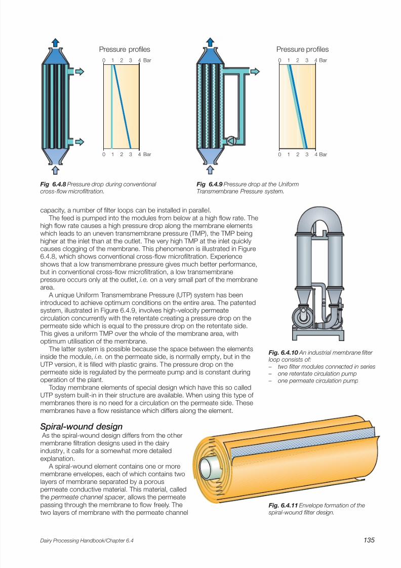
Spiral-wound design As the spiral-wound design differs from the othermembrane filtration designs used in the dairyindustry, it calls for a somewhat more detailedexplanation.
A spiral-wound element contains one or moremembrane envelopes, each of which contains twolayers of membrane separated by a porouspermeate conductive material. This material, called
the permeate channel spacer , allows the permeatepassing through the membrane to flow freely. Thetwo layers of membrane with the permeate channel
0 1 2 3 4
0 1 2 3 4 Bar
Bar
Pressure profiles
0 1 2 3 4
0 1 2 3 4 Bar
Bar
Pressure profiles
Fig. 6.4.11 Envelope formation of the
spiral-wound filter design.
7/27/2019 Membrane Filters_Dairy Processing Hand Book
http://slidepdf.com/reader/full/membrane-filtersdairy-processing-hand-book 6/10
Dairy Processing Handbook/Chapter 6.4136
spacer between them are sealed with adhesive attwo edges and one end to form the membraneenvelope. The open end of the envelope isconnected and sealed to a perforated permeate-collecting tube. The envelope configuration isillustrated in Figure 6.4.11.
A plastic netting material, serving as a channelfor the flow of feed solution through the systemand known as the feed channel spacer, is placed
in contact with one side of each membrane envelope. Due tothe netting design the feed spacers also act as turbulencegenerators to keep the membrane clean at relatively lowvelocities.
The entire assembly is then wrapped around the perforatedpermeate-collecting tube to form the spiral-wound membrane.
Spiral-wound membranes are equipped with an antitelescopingdevice (Figure 6.4.12) between the downstream ends of the membraneelements to prevent the velocity of treated fluid from causing the layers toslip.
Several elements – normally three – can be connected in series inside
the same stainless steel tube as shown in Figure 6.4.13.Membrane and permeate spacer material: polymer.
Fig. 6.4.12 Spiral-wound
membrane with the antitele-
scoping device.
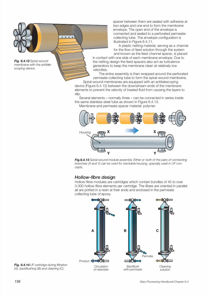
Hollow-fibre designHollow-fibre modules are cartridges which contain bundles of 45 to over3 000 hollow-fibre elements per cartridge. The fibres are oriented in parallel;all are potted in a resin at their ends and enclosed in the permeatecollecting tube of epoxy.
A B C
Circulationof retentate
Backflushwith permeate
Permate
Cleaning solution
Product
Fig. 6.4.14 UF cartridge during filtration(A), backflushing (B) and cleaning (C).
X
Y
X
Y
Housing
Fig.6.4.13 Spiral-wound module assembly. Either or both of the pairs of connecting
branches (X and Y) can be used for stackable housing, specially used in UF con-cepts.
7/27/2019 Membrane Filters_Dairy Processing Hand Book
http://slidepdf.com/reader/full/membrane-filtersdairy-processing-hand-book 7/10
Dairy Processing Handbook/Chapter 6.4 137
The membrane has an inner diameter ranging from 0,5 to 2,7 mm, andthe active membrane surface is on the inside of the hollow fibre. Theoutside of the hollow-fibre wall, unlike the inner wall, has a rough structureand acts as a supporting structure for the membrane. The feed streamflows through the inside of these fibres, and the permeate is collectedoutside and removed at the top of the tube.
A special feature of this design is its backflushing capability, which isutilised in cleaning and with permeate recirculated through the outer per-meate connection to remove product deposits on the membrane surface. Various modes of operation of a hollow-fibre module are illustrated in Figure6.4.14.
Membrane material: polymers.
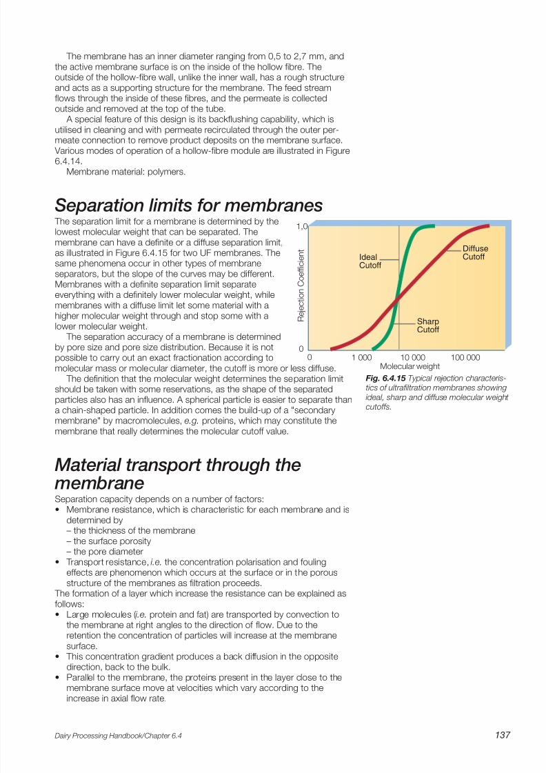
Separation limits for membranes The separation limit for a membrane is determined by thelowest molecular weight that can be separated. Themembrane can have a definite or a diffuse separation limit,as illustrated in Figure 6.4.15 for two UF membranes. Thesame phenomena occur in other types of membrane
separators, but the slope of the curves may be different.Membranes with a definite separation limit separateeverything with a definitely lower molecular weight, whilemembranes with a diffuse limit let some material with ahigher molecular weight through and stop some with alower molecular weight.
The separation accuracy of a membrane is determinedby pore size and pore size distribution. Because it is notpossible to carry out an exact fractionation according tomolecular mass or molecular diameter, the cutoff is more or less diffuse.
The definition that the molecular weight determines the separation limitshould be taken with some reservations, as the shape of the separatedparticles also has an influence. A spherical particle is easier to separate thana chain-shaped particle. In addition comes the build-up of a "secondarymembrane" by macromolecules, e.g. proteins, which may constitute themembrane that really determines the molecular cutoff value.
Material transport through the membraneSeparation capacity depends on a number of factors:• Membrane resistance, which is characteristic for each membrane and is
determined by– the thickness of the membrane
– the surface porosity– the pore diameter
• Transport resistance, i.e. the concentration polarisation and foulingeffects are phenomenon which occurs at the surface or in the porousstructure of the membranes as filtration proceeds.
The formation of a layer which increase the resistance can be explained asfollows:• Large molecules ( i.e. protein and fat) are transported by convection to
the membrane at right angles to the direction of flow. Due to theretention the concentration of particles will increase at the membranesurface.
• This concentration gradient produces a back diffusion in the oppositedirection, back to the bulk.
• Parallel to the membrane, the proteins present in the layer close to themembrane surface move at velocities which vary according to theincrease in axial flow rate.
1,0
0100 00010 0001 0000
IdealCutoff
SharpCutoff
DiffuseCutoff
R e j e c t i o n C o e f f i c i e n t
Molecular weight
Fig. 6.4.15 Typical rejection characteris-tics of ultrafiltration membranes showing
ideal, sharp and diffuse molecular weight
cutoffs.

7/27/2019 Membrane Filters_Dairy Processing Hand Book
http://slidepdf.com/reader/full/membrane-filtersdairy-processing-hand-book 8/10
Dairy Processing Handbook/Chapter 6.4138
• The fouling effect is not uniformly distributed along the membrane,especially when the pressure drop gives different transmembranepressures (TMP) along the membrane surface. The upstream end of themembrane is therefore clogged first. The fouling graduallyspreads over the whole surface, reducing capacity and eventuallymaking it necessary to stop and clean the plant.
• The main effect of fouling is that the removal of permeate decreasesas filtration proceeds.
• The fouling effect can be reduced in certain concepts by usingbackflush, reverse flow or UTP (possible when ceramic membranesare used).
Pressure conditionsPressure is the driving force of filtration, and an important distinction mustbe made between:1 The hydraulic pressure drop along the module P = P
1- P
2.
The higher the velocity through the module the higher the value of P. A higher velocity results in a higher shear at the membrane surface and alower polarisation effect. However, there are constraints such as theresistance to pressure of the membrane and the price of pumps capable
of delivering both high flows and high pressure.2 The transmembrane pressure (TMP) is the pressure drop between the
retentate and the permeate sides of the membrane at a particular pointalong the membrane. The main criterion of the efficiency of a membranesystem is expressed as the flux – the flow per membranes area andhour, l/m2 /h, and is a function of TMP.
The TMP, i.e. the force which pushes the permeate through the membrane,is greatest at the inlet and lowest at the discharge end of the module. Sincethe decrease in TMP is linear, an average TMP is given by:
Fig. 6.4.16 Hydraulic (A) and transmembrane (B) pressure drops over a membrane
P2
P3
P1
P3 P2
P1
A B
0 bar
P1 = inlet pressure feed
P2 = outlet pressure concentrate
P3 = outlet pressure permeate
Pressure profiles
TMP = – P3
P1+ P
2
2
P = P1 – P
2 TMP = – P
3
P1+ P
2
2
The hydraulic pressure drop over the membrane (A) and thetransmembrane pressure profile (B) are illustrated in Figure 6.4.16.

7/27/2019 Membrane Filters_Dairy Processing Hand Book
http://slidepdf.com/reader/full/membrane-filtersdairy-processing-hand-book 9/10
Dairy Processing Handbook/Chapter 6.4 139
Principles of plant designs The operation of membrane filtration plants depends
basically on the pressure generated by the pumps used. The following guides should be taken into consideration:1 The capacity of the pump(s) should match the required
flow rate and the characteristics of the module(s), whichvary widely according to module design and size.
2 The pump(s) should be insensitive to changes in theviscosity of the processed stream up to the viscositylimit of the module. It/they should also operate efficientlyat the temperatures used for processsing and cleaning.
3 The pump(s) must satisfy the sanitary standards fordairy equipment.Pumps of several types are used, including centrifugal
pumps and positive displacement pumps. Sanitary cen-
trifugal pumps are normally used as feed and circulationpumps, but sanitary positive displacement pumps areoccasionally used as high-pressure feed and circulationpumps for high-viscosity liquids, e.g. in the final stages of ultrafiltration of acidified milk.
Membrane separation plants can be used for bothbatch and continuous production. The feed solution must not contain coarse particles, which can damage the verythin filtration layer/active layer. A fine-meshed strainer istherefore often integrated into the feed system.
Batch productionPlants for batch production (Figure 6.4.17) are used mainlyfor filtration of small volumes of product, for example inlaboratories and experimental plants. A certain amount of the product to be treated is kept in a buffer tank. Theproduct is circulated through the membrane separator untilthe required concentration is obtained.
Continuous productionSchematic designs of the membrane filtration plants re-ferred to are collected in Figures 6.4.18. and 6.4.19. Theplants illustrated in Figure 6.4.18 represent spiral-woundconcepts for RO, NF and UF applications, with polymermembranes of different pore sizes, while Figure 6.4.19
shows a MF plant with ceramic membranes. As the RO membranes are much tighter than those of the two other
systems, a higher inlet pressure is required for production. This is main-
Fig. 6.4.17 Batch membrane filtration plant
1
2 3
4
5
6
Feed product Concentration loopPermeateCooling medium
1 Product tank
2 Feed pump 3 Circulation pump
4 Strainer 5 Membrane module
6 Cooler
1
2
3
1
2
3
1
2
3
RO concept
NF concept
UF concept
Fig. 6.4.18 Design principles for different
filter loops.
1 Membrane 2 Cooler 3 Strainer

7/27/2019 Membrane Filters_Dairy Processing Hand Book
http://slidepdf.com/reader/full/membrane-filtersdairy-processing-hand-book 10/10
Dairy Processing Handbook/Chapter 6.4140
1
2
1Feed product Retentate
Permeate
Fig. 6.4.19 Design principle of a MF filter loop.
1 MF membrane cartridge 2 Circulation pump for retentate
Fig. 6.4.20 Production module for UF processing.
tained by three sanitary centrifugal feed pumps in series and one sanitary
centrifugal circulation pump. The other two filtration plants, NF and UF, have more open membranesand can therefore manage with two feed pumps and one feed pumprespectively.
As was mentioned earlier, the MF concept is based on two filter modulesoperated in series in a filter loop system which also contains one centrifugalpump for circulation of the retentate and one for circulation of the permeate.
The feed solution may be supplied from a separation plant with a systemfor constant pressure at the outlet, or from a balance tank equipped with apump and a system for capacity regulation.
Processing temperature in membranefiltration applicationsIn most cases, the processing temperature is about 50 °C for dairyapplications. Filtration plants are normally supplemented with a simplecooling system integrated into the internal circulation loop to compensatefor the slight rise in temperature that occurs during operation and tomaintain a constant processing temperature.