Embed Size (px)
Citation preview

ST1103010 channels
USER MANUAL
rev. 0.4
24th March 2016
ST1 10 ch. Hardware&Software 1
Index
1 GENERAL NOTES....................................................................................................................................................4
1.1 Introduction........................................................................................................................................................................4
2 HARDWARE CHARACTERISTICS....................................................................................................................................................6
2.1 Dip-switchs........................................................................................................................................................................82.2 Analog inputs.....................................................................................................................................................................92.3 ST1 1030............................................................................................................................................................................92.4 RS485 communication cable.............................................................................................................................................10
3 MEMORY MAP....................................................................................................................................................11
ST1 10 ch. Hardware&Software 2
Kernel Sistemi s.r.l.
1 GENERAL NOTES
1.1 Introduction
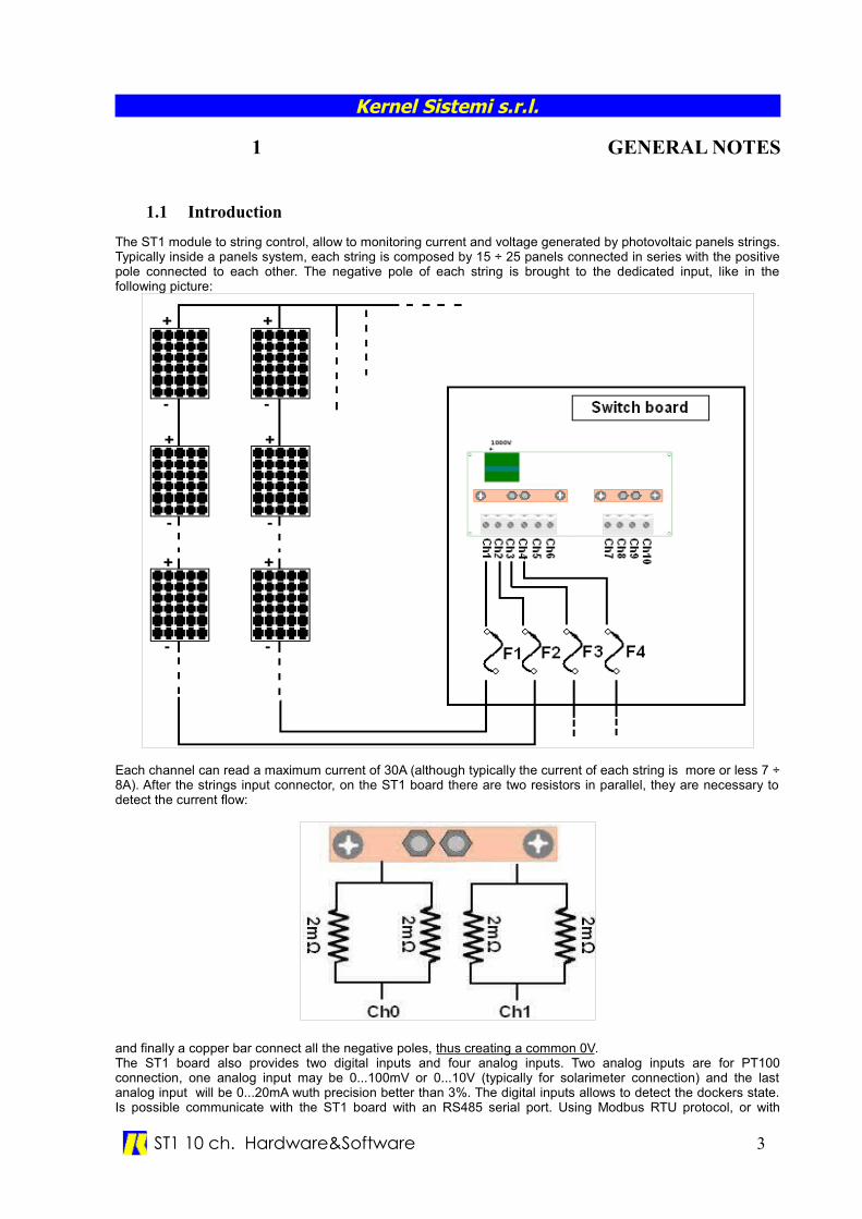
The ST1 module to string control, allow to monitoring current and voltage generated by photovoltaic panels strings.Typically inside a panels system, each string is composed by 15 ÷ 25 panels connected in series with the positivepole connected to each other. The negative pole of each string is brought to the dedicated input, like in thefollowing picture:
Each channel can read a maximum current of 30A (although typically the current of each string is more or less 7 ÷8A). After the strings input connector, on the ST1 board there are two resistors in parallel, they are necessary todetect the current flow:
and finally a copper bar connect all the negative poles, thus creating a common 0V.The ST1 board also provides two digital inputs and four analog inputs. Two analog inputs are for PT100connection, one analog input may be 0...100mV or 0...10V (typically for solarimeter connection) and the lastanalog input will be 0...20mA wuth precision better than 3%. The digital inputs allows to detect the dockers state.Is possible communicate with the ST1 board with an RS485 serial port. Using Modbus RTU protocol, or with
ST1 10 ch. Hardware&Software 3
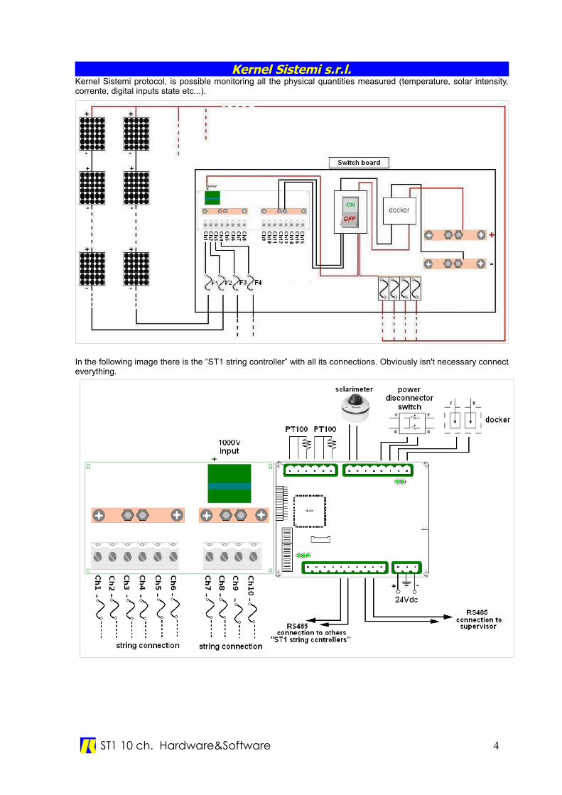
Kernel Sistemi s.r.l.Kernel Sistemi protocol, is possible monitoring all the physical quantities measured (temperature, solar intensity,corrente, digital inputs state etc...).
In the following image there is the “ST1 string controller” with all its connections. Obviously isn't necessary connecteverything.
ST1 10 ch. Hardware&Software 4
Kernel Sistemi s.r.l.
2 HARDWARECHARACTERISTICS
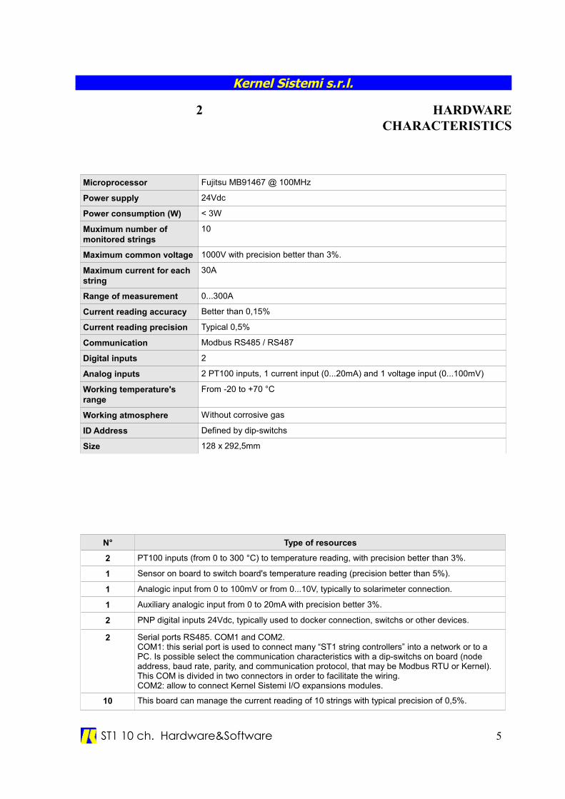
Microprocessor Fujitsu MB91467 @ 100MHz
Power supply 24Vdc
Power consumption (W) < 3W
Muximum number of monitored strings
10
Maximum common voltage 1000V with precision better than 3%.
Maximum current for each string
30A
Range of measurement 0...300A
Current reading accuracy Better than 0,15%
Current reading precision Typical 0,5%
Communication Modbus RS485 / RS487
Digital inputs 2
Analog inputs 2 PT100 inputs, 1 current input (0...20mA) and 1 voltage input (0...100mV)
Working temperature's range
From -20 to +70 °C
Working atmosphere Without corrosive gas
ID Address Defined by dip-switchs
Size 128 x 292,5mm
N° Type of resources
2 PT100 inputs (from 0 to 300 °C) to temperature reading, with precision better than 3%.
1 Sensor on board to switch board's temperature reading (precision better than 5%).
1 Analogic input from 0 to 100mV or from 0...10V, typically to solarimeter connection.
1 Auxiliary analogic input from 0 to 20mA with precision better 3%.
2 PNP digital inputs 24Vdc, typically used to docker connection, switchs or other devices.
2 Serial ports RS485. COM1 and COM2.COM1: this serial port is used to connect many “ST1 string controllers” into a network or to a PC. Is possible select the communication characteristics with a dip-switchs on board (node address, baud rate, parity, and communication protocol, that may be Modbus RTU or Kernel). This COM is divided in two connectors in order to facilitate the wiring.COM2: allow to connect Kernel Sistemi I/O expansions modules.
10 This board can manage the current reading of 10 strings with typical precision of 0,5%.
ST1 10 ch. Hardware&Software 5
Kernel Sistemi s.r.l.
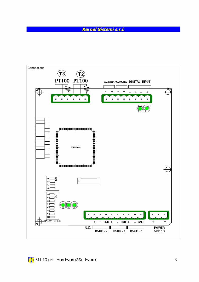
Connections
ST1 10 ch. Hardware&Software 6
Kernel Sistemi s.r.l.
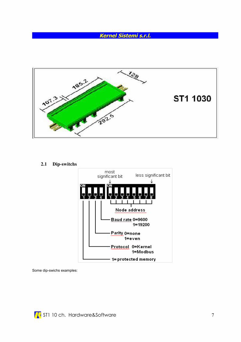
2.1 Dip-switchs
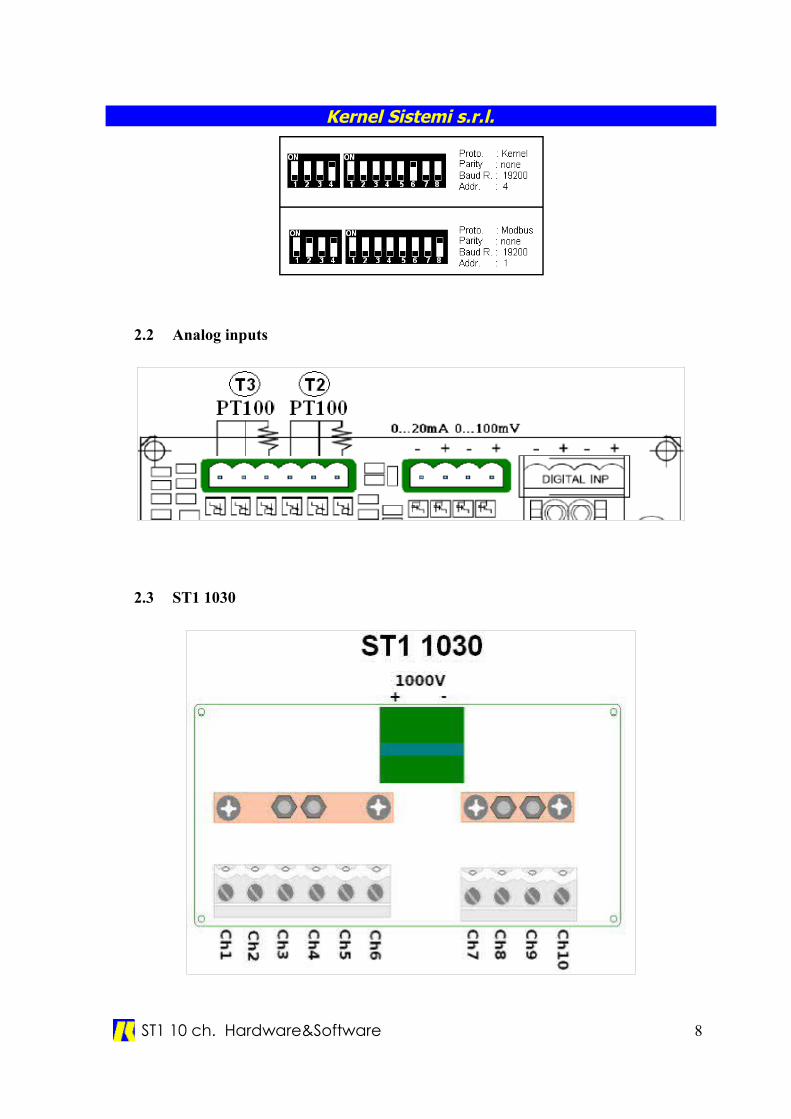
Some dip-swichs examples:
ST1 10 ch. Hardware&Software 7
Kernel Sistemi s.r.l.
2.2 Analog inputs
2.3 ST1 1030
ST1 10 ch. Hardware&Software 8
Kernel Sistemi s.r.l.
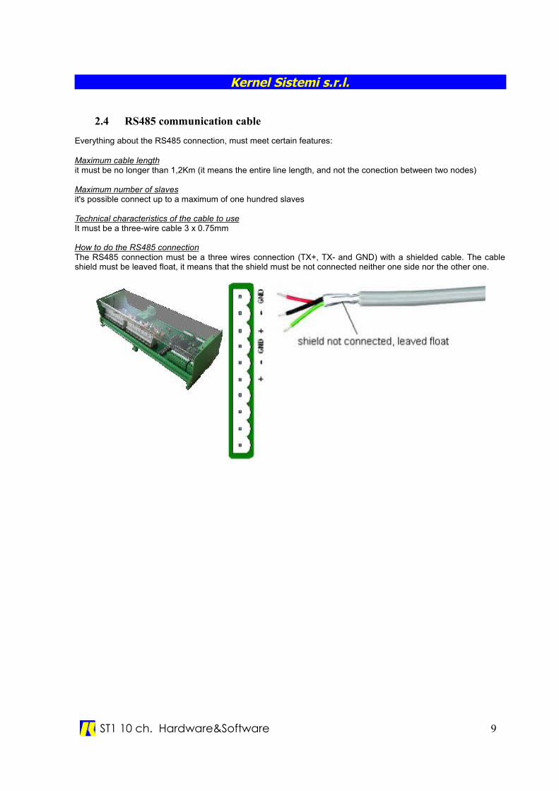
2.4 RS485 communication cable
Everything about the RS485 connection, must meet certain features:
Maximum cable lengthit must be no longer than 1,2Km (it means the entire line length, and not the conection between two nodes)
Maximum number of slavesit's possible connect up to a maximum of one hundred slaves
Technical characteristics of the cable to useIt must be a three-wire cable 3 x 0.75mm
How to do the RS485 connectionThe RS485 connection must be a three wires connection (TX+, TX- and GND) with a shielded cable. The cableshield must be leaved float, it means that the shield must be not connected neither one side nor the other one.
ST1 10 ch. Hardware&Software 9
Kernel Sistemi s.r.l.
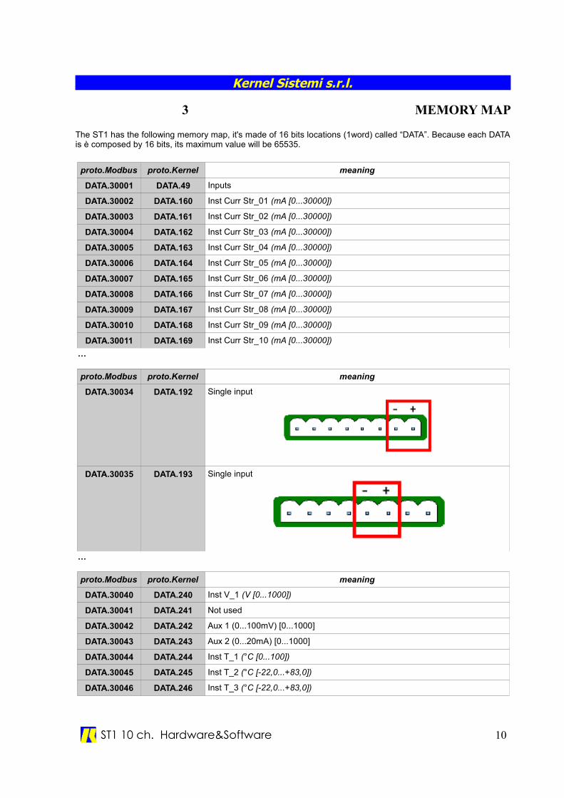
3 MEMORY MAP
The ST1 has the following memory map, it's made of 16 bits locations (1word) called “DATA”. Because each DATAis è composed by 16 bits, its maximum value will be 65535.
proto.Modbus proto.Kernel meaning
DATA.30001 DATA.49 Inputs
DATA.30002 DATA.160 Inst Curr Str_01 (mA [0...30000])
DATA.30003 DATA.161 Inst Curr Str_02 (mA [0...30000])
DATA.30004 DATA.162 Inst Curr Str_03 (mA [0...30000])
DATA.30005 DATA.163 Inst Curr Str_04 (mA [0...30000])
DATA.30006 DATA.164 Inst Curr Str_05 (mA [0...30000])
DATA.30007 DATA.165 Inst Curr Str_06 (mA [0...30000])
DATA.30008 DATA.166 Inst Curr Str_07 (mA [0...30000])
DATA.30009 DATA.167 Inst Curr Str_08 (mA [0...30000])
DATA.30010 DATA.168 Inst Curr Str_09 (mA [0...30000])
DATA.30011 DATA.169 Inst Curr Str_10 (mA [0...30000])
…
proto.Modbus proto.Kernel meaning
DATA.30034 DATA.192 Single input
DATA.30035 DATA.193 Single input
…
proto.Modbus proto.Kernel meaning
DATA.30040 DATA.240 Inst V_1 (V [0...1000])
DATA.30041 DATA.241 Not used
DATA.30042 DATA.242 Aux 1 (0...100mV) [0...1000]
DATA.30043 DATA.243 Aux 2 (0...20mA) [0...1000]
DATA.30044 DATA.244 Inst T_1 (°C [0...100])
DATA.30045 DATA.245 Inst T_2 (°C [-22,0...+83,0])
DATA.30046 DATA.246 Inst T_3 (°C [-22,0...+83,0])
ST1 10 ch. Hardware&Software 10
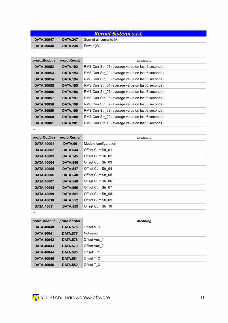
Kernel Sistemi s.r.l.DATA.30047 DATA.247 Sum of all currents (A)
DATA.30048 DATA.248 Power (W)
…
proto.Modbus proto.Kernel meaning
DATA.30052 DATA.192 RMS Curr Str_01 (average value on last 6 seconds)
DATA.30053 DATA.193 RMS Curr Str_02 (average value on last 6 seconds)
DATA.30054 DATA.194 RMS Curr Str_03 (average value on last 6 seconds)
DATA.30055 DATA.195 RMS Curr Str_04 (average value on last 6 seconds)
DATA.30056 DATA.196 RMS Curr Str_05 (average value on last 6 seconds)
DATA.30057 DATA.197 RMS Curr Str_06 (average value on last 6 seconds)
DATA.30058 DATA.198 RMS Curr Str_07 (average value on last 6 seconds)
DATA.30059 DATA.199 RMS Curr Str_08 (average value on last 6 seconds)
DATA.30060 DATA.200 RMS Curr Str_09 (average value on last 6 seconds)
DATA.30061 DATA.201 RMS Curr Str_10 (average value on last 6 seconds)
…
proto.Modbus proto.Kernel meaning
DATA.40001 DATA.00 Module configuration
DATA.40002 DATA.544 Offset Curr Str_01
DATA.40003 DATA.545 Offset Curr Str_02
DATA.40004 DATA.546 Offset Curr Str_03
DATA.40005 DATA.547 Offset Curr Str_04
DATA.40006 DATA.548 Offset Curr Str_05
DATA.40007 DATA.549 Offset Curr Str_06
DATA.40008 DATA.550 Offset Curr Str_07
DATA.40009 DATA.551 Offset Curr Str_08
DATA.40010 DATA.552 Offset Curr Str_09
DATA.40011 DATA.553 Offset Curr Str_10
…
proto.Modbus proto.Kernel meaning
DATA.40040 DATA.576 Offset V_1
DATA.40041 DATA.577 Not used
DATA.40042 DATA.578 Offset Aux_1
DATA.40043 DATA.579 Offset Aux_2
DATA.40044 DATA.580 Offset T_1
DATA.40045 DATA.581 Offset T_2
DATA.40046 DATA.582 Offset T_3
…
ST1 10 ch. Hardware&Software 11
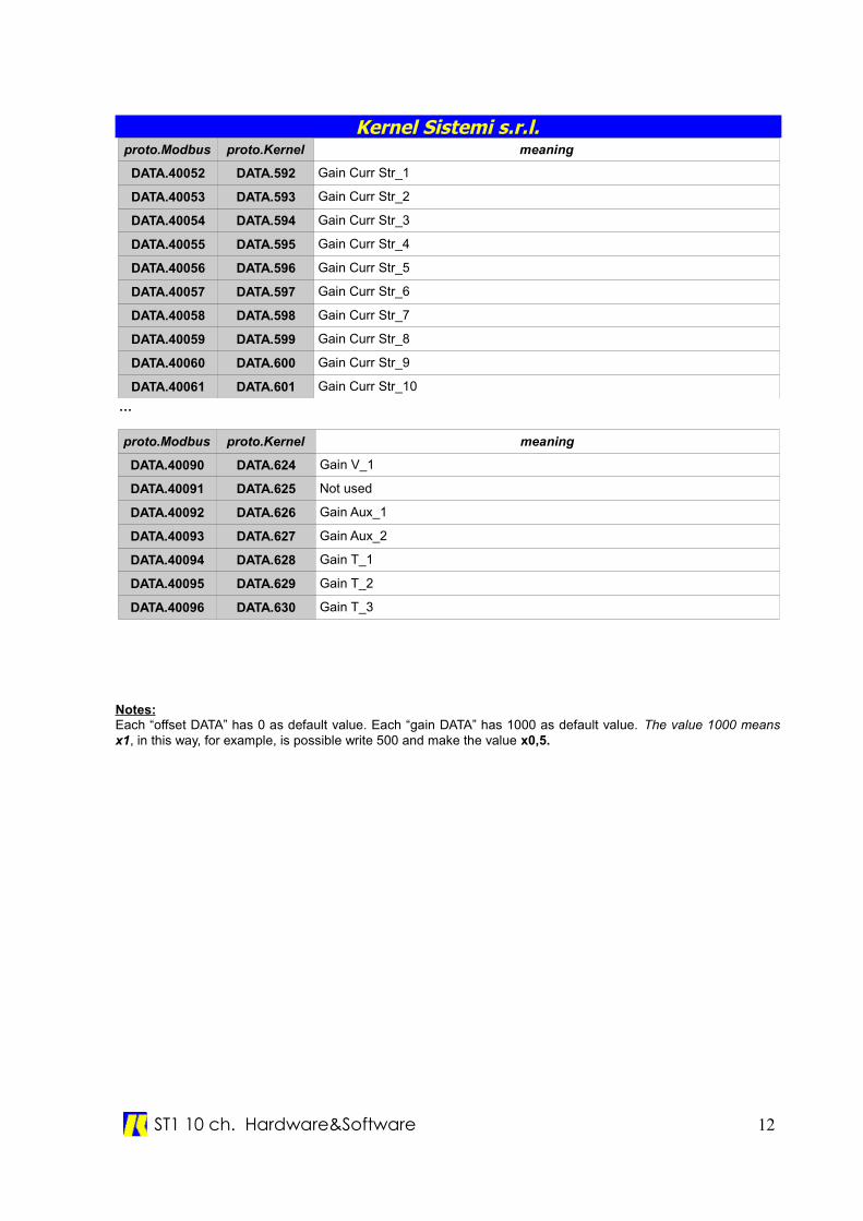
Kernel Sistemi s.r.l.proto.Modbus proto.Kernel meaning
DATA.40052 DATA.592 Gain Curr Str_1
DATA.40053 DATA.593 Gain Curr Str_2
DATA.40054 DATA.594 Gain Curr Str_3
DATA.40055 DATA.595 Gain Curr Str_4
DATA.40056 DATA.596 Gain Curr Str_5
DATA.40057 DATA.597 Gain Curr Str_6
DATA.40058 DATA.598 Gain Curr Str_7
DATA.40059 DATA.599 Gain Curr Str_8
DATA.40060 DATA.600 Gain Curr Str_9
DATA.40061 DATA.601 Gain Curr Str_10
…
proto.Modbus proto.Kernel meaning
DATA.40090 DATA.624 Gain V_1
DATA.40091 DATA.625 Not used
DATA.40092 DATA.626 Gain Aux_1
DATA.40093 DATA.627 Gain Aux_2
DATA.40094 DATA.628 Gain T_1
DATA.40095 DATA.629 Gain T_2
DATA.40096 DATA.630 Gain T_3
Notes:Each “offset DATA” has 0 as default value. Each “gain DATA” has 1000 as default value. The value 1000 meansx1, in this way, for example, is possible write 500 and make the value x0,5.
ST1 10 ch. Hardware&Software 12