Embed Size (px)
Citation preview
Intel® Optane™ DC Persistent
Memory Module (DCPMM) - DSM
Interface
Revision V1.8
October, 2018 The following changes make up the publically released DSM V1.8 specification available on http://pmem.io/documents/:
- Get SMART Health Info: o Renamed Spare Blocks Remaining field and Validity bit to Percentage Remaining
o Added Health Status Reason field and new validity bit o Percentage Used has been deprecated and renamed Reserved o Added notes to DSC and LSS that these indicators are both controlled by the LSS latch enable logic o Add DCPMM Specific SMART Data using new Table 3-3 o Rename Vendor Specific Data to DCPMM Specific Data
- Get SMART Threshold - Set SMART Threshold
o Renamed Spare Blocks Remaining field to Percentage Remaining
- NVDIMM Security Management
o Addition of Master Passphrase support to match FIS 1.13 o Addition missing return status 01 - Failure - Function Not Supported returned for most security
commands if not in correct state
o Theory of Operation – Updated Application In-band Get Security State Sequence diagram with Master
Passphrase additions
o Get Security State
Updated both flows for Security Theory of Operation section. Note the updated
GetSecurityState DSM status checking. These are clarifications only and not a logic change
Add new return values to report Master Passphrase Enabled and Master Passphrase Limit
Expired to match FIS 1.13
Added Extended Security State field to allow backwards compatibility with the V1.7 DSM spec
o Set Master Passphrase New DSM to match FIS 1.13 addition of Master Passphrase feature
o Secure Erase NVDIMM
Updated responsibilities to better explain invalidating CPU caches
Renamed Secure Erase NVDIMM w User Passphrase
o Secure Erase NVDIMM w Master Passphrase
New command to avoid changes to existing Secure Erase feature
o Unlock Unit
Added missing responsibility to invalidate CPU caches after an Unlock Unit has completed
IntelOptaneDC DSM Interface – V1.8
2
Notices
No license (express or implied, by estoppel or otherwise) to any intellectual property rights is granted by this
document.
Intel disclaims all express and implied warranties, including without limitation, the implied warranties of
merchantability, fitness for a particular purpose, and non-infringement, as well as any warranty arising from course
of performance, course of dealing, or usage in trade.
This document contains information on products, services and/or processes in development. All information
provided here is subject to change without notice. Contact your Intel representative to obtain the latest forecast,
schedule, specifications and roadmaps.
The products and services described may contain defects or errors known as errata which may cause deviations
from published specifications. Current characterized errata are available on request.
Copies of documents which have an order number and are referenced in this document may be obtained by calling
1-800-548-4725 or by visiting www.intel.com/design/literature.htm.
Intel and the Intel logo are trademarks of Intel Corporation in the U.S. and/or other countries.
*Other names and brands may be claimed as the property of others
© 2015-2018 Intel Corporation.
IntelOptaneDC DSM Interface – V1.8
3
Contents
Contents 1 Introduction ........................................................................................... 5
Document Scope ..................................................................................... 5 Related Documents ................................................................................. 5 Terminology ........................................................................................... 5
2 _DSM Interface for NVDIMM ACPI0012 Root Device ..................................... 6 3 _DSM Interface for the NVDIMM Device ..................................................... 7
SMART Health Monitoring & Alarms ......................................................... 10
3.1.1 Get SMART and Health Info (Function Index 1) .................................... 10
3.1.2 Get SMART Threshold (Function Index 2)............................................. 15
3.1.3 Set SMART Threshold (Function Index 17) ........................................... 17
Command Effect Log ............................................................................. 19
3.2.1 Get Command Effect Log Info (Function Index 7) ................................ 19
3.2.2 Get Command Effect Log (Function Index 8) ........................................ 20
Pass-Through Command (Function Index 9) ............................................. 22 Enable Latch System Shutdown Status (Function Index 10) ........................ 23 Get Supported Modes (Function Index 11) ............................................... 24 NVDIMM FW Download........................................................................... 25
3.6.1 Get FW Info (Function Index 12)........................................................... 25
3.6.2 Start FW Update (Function Index 13) ................................................... 27
3.6.3 Send FW Update Data (Function Index 14) .......................................... 29
3.6.4 Finish FW Update (Function Index 15) ................................................. 31
3.6.5 Query Finish FW Update Status (Function Index 16) ............................ 33
Inject Error (Function Index 18) .............................................................. 35 NVDIMM Security Management ............................................................... 38
3.8.1 Theory Of Operation ............................................................................. 38
3.8.2 Get Security State (Function Index 19) ................................................. 41
3.8.3 Set Passphrase (Function Index 20) ...................................................... 44
3.8.4 Disable Passphrase (Function Index 21) ............................................... 45
3.8.5 Unlock Unit (Function Index 22) ........................................................... 46
3.8.6 Freeze Lock (Function Index 23) ........................................................... 47
IntelOptaneDC DSM Interface – V1.8
4
3.8.7 Secure Erase NVDIMM w User Passphrase (Function Index 24) .......... 48
3.8.8 Overwrite NVDIMM (Function Index 25) .............................................. 50
3.8.9 Query Overwrite NVDIMM Status (Function Index 26) ........................ 52
3.8.10 Set Master Passphrase (Function Index 27) ......................................... 54
3.8.11 Secure Erase NVDIMM w Master Passphrase (Function Index 28) ...... 56
Deprecated Functions ............................................................................ 58
3.9.1 Get Block NVDIMM Flags (Function Index 3) ........................................ 58
3.9.2 Get Namespace Label Size (Function Index 4) ...................................... 59
3.9.3 Get Namespace Label Data (Function Index 5) .................................... 60
3.9.4 Set Namespace Label Data (Function Index 6) ..................................... 61
IntelOptaneDC DSM Interface – V1.8
5
1 Introduction
Document Scope This document is targeted to writers of BIOS and OS drivers for NVDIMMs whose design adheres to the
NFIT Tables in the ACPI V6.2 specification. This document specifically discusses the NVDIMM Device
Specific Method (_DSM).
Related Documents The related documents are:
ACPI Specification Version 6.0, 6.1 & 6.2, 6.2 Errata A (http://www.uefi.org/specifications)
UEFI 2.7, 2.7 Errata A - NVDIMM Label Protocol, UEFI 2.7 NVDIMM BTT Layout
(http://www.uefi.org/specifications)
This DSM Specification (http://pmem.io/documents)
Terminology Refer to Table 1-1 for definitions of terms used in this document.
Table 1-1 – Terminology
Term Description
Intel® Optane™ DC Persistent Memory Module or DCPMM or NVDIMM
The non-volatile DDR DIMM form factor byte addressable PMEM. Also referred to throughout this specification as the NVDIMM or DCPMM.
NFIT The NVDIMM Firmware Interface Table defines the ACPI 6.2 specified information created by the BIOS to inform the OS about NVDIMMs in the system.
NVDIMM Non-volatile memory in a DIMM form factor. See DCPMM above.
NVDIMM Namespace Label Labels, stored at a known location on NVDIMMs, which define the DIMM’s contribution to NVDIMM Namespaces. This is a software mechanism; the DIMM itself just sees the labels as part of the overall data stored on the DIMM. See the ACPI 6.2 NVDIMM Label additions and the UEFI 2.7 NVDIMM Label Protocol additions to describe this in more detail.
NVDIMM Namespace Similar to an NVMe Namespace or a Logical Unit (LUN) on a SCSI disk, this is a software mechanism for managing ranges of persistence on NVDIMMs. See the ACPI 6.2 NVDIMM Label additions, and the UEFI 2.7 NVDIMM Label Protocol additions to describe this in more detail.
Persistent Memory Byte-addressable memory that retains its contents after power loss.
SPA System Physical Address. A physical address on the host operating system.
IntelOptaneDC DSM Interface – V1.8
6
2 _DSM Interface for NVDIMM ACPI0012 Root Device
All Root ACPI0012 scoped _DSMs and NVDIMM layout / Label interfaces are now found in the following
specifications and have been removed from this document, which will now only document the Intel
NVDIMM specific _DSMs.
Please see:
ACPI Specification V6.0 – Initial NVDIMM NFIT additions
ACPI Specification V6.1 – Addition of Common ARS _DSMs, Clear Uncorrectable Error _DSM
ACPI Specification V6.2 – Addition of NVDIMM Label API, ARS Error Injection _DSMs
ACPI Specification V6.2 Errata A – Addition of RAS Capabilities structure as a new NFIT structure
UEFI Specification V2.7 – See additions of NVDIMM Label Protocol and BTT Layout
UEFI Specification V2.7 Errata A – Small fixes to the Label Protocol that remove inconsistencies with
existing implementations
IntelOptaneDC DSM Interface – V1.8
7
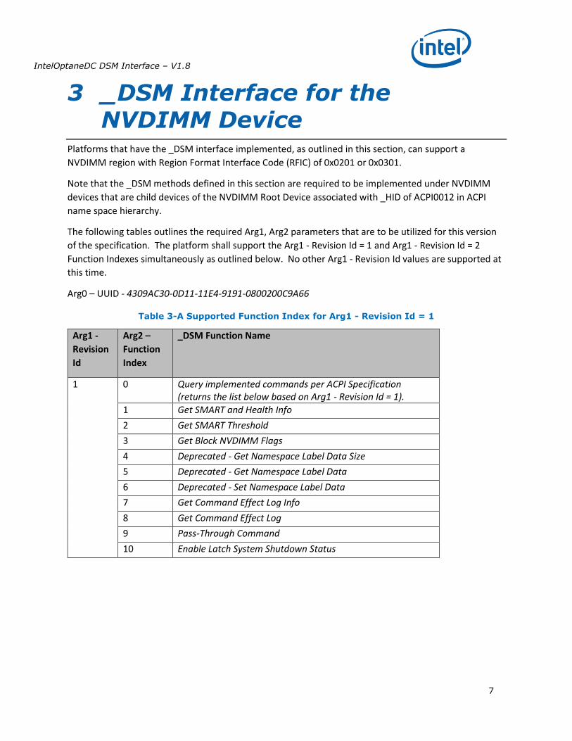
3 _DSM Interface for the NVDIMM Device
Platforms that have the _DSM interface implemented, as outlined in this section, can support a
NVDIMM region with Region Format Interface Code (RFIC) of 0x0201 or 0x0301.
Note that the _DSM methods defined in this section are required to be implemented under NVDIMM
devices that are child devices of the NVDIMM Root Device associated with _HID of ACPI0012 in ACPI
name space hierarchy.
The following tables outlines the required Arg1, Arg2 parameters that are to be utilized for this version
of the specification. The platform shall support the Arg1 - Revision Id = 1 and Arg1 - Revision Id = 2
Function Indexes simultaneously as outlined below. No other Arg1 - Revision Id values are supported at
this time.
Arg0 – UUID - 4309AC30-0D11-11E4-9191-0800200C9A66
Table 3-A Supported Function Index for Arg1 - Revision Id = 1
Arg1 -
Revision
Id
Arg2 –
Function
Index
_DSM Function Name
1 0 Query implemented commands per ACPI Specification (returns the list below based on Arg1 - Revision Id = 1).
1 Get SMART and Health Info
2 Get SMART Threshold
3 Get Block NVDIMM Flags
4 Deprecated - Get Namespace Label Data Size
5 Deprecated - Get Namespace Label Data
6 Deprecated - Set Namespace Label Data
7 Get Command Effect Log Info
8 Get Command Effect Log
9 Pass-Through Command
10 Enable Latch System Shutdown Status
IntelOptaneDC DSM Interface – V1.8
8
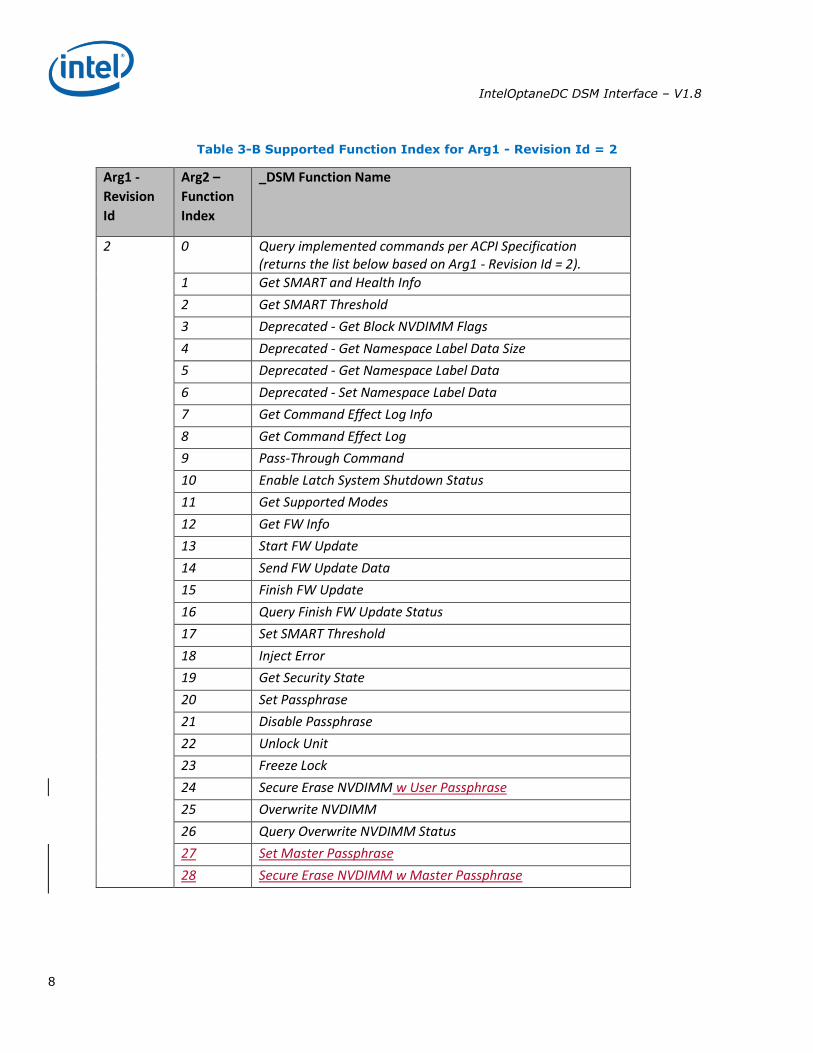
Table 3-B Supported Function Index for Arg1 - Revision Id = 2
Arg1 -
Revision
Id
Arg2 –
Function
Index
_DSM Function Name
2 0 Query implemented commands per ACPI Specification (returns the list below based on Arg1 - Revision Id = 2).
1 Get SMART and Health Info
2 Get SMART Threshold
3 Deprecated - Get Block NVDIMM Flags
4 Deprecated - Get Namespace Label Data Size
5 Deprecated - Get Namespace Label Data
6 Deprecated - Set Namespace Label Data
7 Get Command Effect Log Info
8 Get Command Effect Log
9 Pass-Through Command
10 Enable Latch System Shutdown Status
11 Get Supported Modes
12 Get FW Info
13 Start FW Update
14 Send FW Update Data
15 Finish FW Update
16 Query Finish FW Update Status
17 Set SMART Threshold
18 Inject Error
19 Get Security State
20 Set Passphrase
21 Disable Passphrase
22 Unlock Unit
23 Freeze Lock
24 Secure Erase NVDIMM w User Passphrase
25 Overwrite NVDIMM
26 Query Overwrite NVDIMM Status
27 Set Master Passphrase
28 Secure Erase NVDIMM w Master Passphrase
IntelOptaneDC DSM Interface – V1.8
9
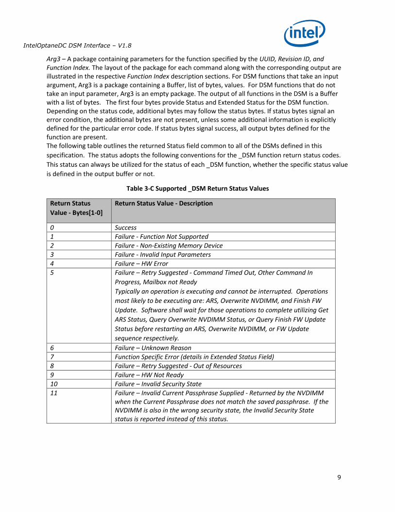
Arg3 – A package containing parameters for the function specified by the UUID, Revision ID, and Function Index. The layout of the package for each command along with the corresponding output are illustrated in the respective Function Index description sections. For DSM functions that take an input argument, Arg3 is a package containing a Buffer, list of bytes, values. For DSM functions that do not take an input parameter, Arg3 is an empty package. The output of all functions in the DSM is a Buffer with a list of bytes. The first four bytes provide Status and Extended Status for the DSM function. Depending on the status code, additional bytes may follow the status bytes. If status bytes signal an error condition, the additional bytes are not present, unless some additional information is explicitly defined for the particular error code. If status bytes signal success, all output bytes defined for the function are present. The following table outlines the returned Status field common to all of the DSMs defined in this
specification. The status adopts the following conventions for the _DSM function return status codes.
This status can always be utilized for the status of each _DSM function, whether the specific status value
is defined in the output buffer or not.
Table 3-C Supported _DSM Return Status Values
Return Status
Value - Bytes[1-0]
Return Status Value - Description
0 Success
1 Failure - Function Not Supported
2 Failure - Non-Existing Memory Device
3 Failure - Invalid Input Parameters
4 Failure – HW Error
5 Failure – Retry Suggested - Command Timed Out, Other Command In
Progress, Mailbox not Ready
Typically an operation is executing and cannot be interrupted. Operations
most likely to be executing are: ARS, Overwrite NVDIMM, and Finish FW
Update. Software shall wait for those operations to complete utilizing Get
ARS Status, Query Overwrite NVDIMM Status, or Query Finish FW Update
Status before restarting an ARS, Overwrite NVDIMM, or FW Update
sequence respectively.
6 Failure – Unknown Reason
7 Function Specific Error (details in Extended Status Field)
8 Failure – Retry Suggested - Out of Resources
9 Failure – HW Not Ready
10 Failure – Invalid Security State
11 Failure – Invalid Current Passphrase Supplied - Returned by the NVDIMM when the Current Passphrase does not match the saved passphrase. If the NVDIMM is also in the wrong security state, the Invalid Security State status is reported instead of this status.
IntelOptaneDC DSM Interface – V1.8
10
SMART Health Monitoring & Alarms
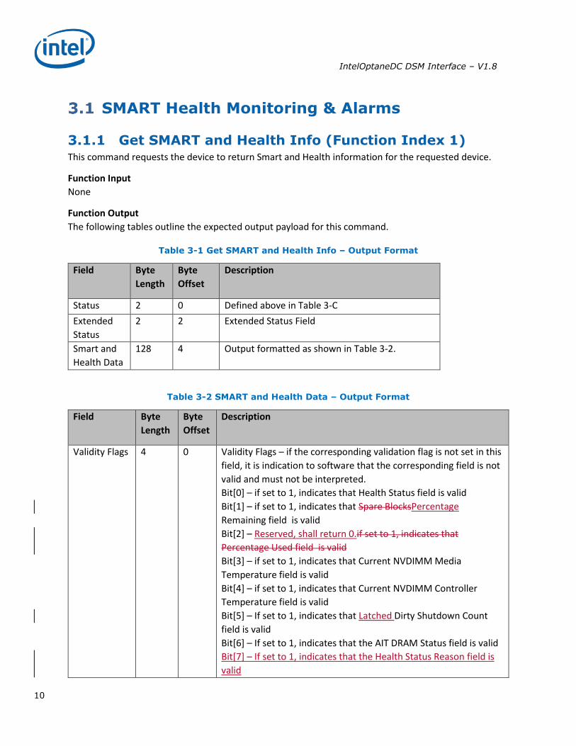
3.1.1 Get SMART and Health Info (Function Index 1) This command requests the device to return Smart and Health information for the requested device.
Function Input
None
Function Output
The following tables outline the expected output payload for this command.
Table 3-1 Get SMART and Health Info – Output Format
Field Byte
Length
Byte
Offset
Description
Status 2 0 Defined above in Table 3-C
Extended
Status
2 2 Extended Status Field
Smart and
Health Data
128 4 Output formatted as shown in Table 3-2.
Table 3-2 SMART and Health Data – Output Format
Field Byte
Length
Byte
Offset
Description
Validity Flags 4 0 Validity Flags – if the corresponding validation flag is not set in this
field, it is indication to software that the corresponding field is not
valid and must not be interpreted.
Bit[0] – if set to 1, indicates that Health Status field is valid
Bit[1] – if set to 1, indicates that Spare BlocksPercentage
Remaining field is valid
Bit[2] – Reserved, shall return 0.if set to 1, indicates that
Percentage Used field is valid
Bit[3] – if set to 1, indicates that Current NVDIMM Media
Temperature field is valid
Bit[4] – if set to 1, indicates that Current NVDIMM Controller
Temperature field is valid
Bit[5] – If set to 1, indicates that Latched Dirty Shutdown Count
field is valid
Bit[6] – If set to 1, indicates that the AIT DRAM Status field is valid
Bit[7] – If set to 1, indicates that the Health Status Reason field is
valid
IntelOptaneDC DSM Interface – V1.8
11
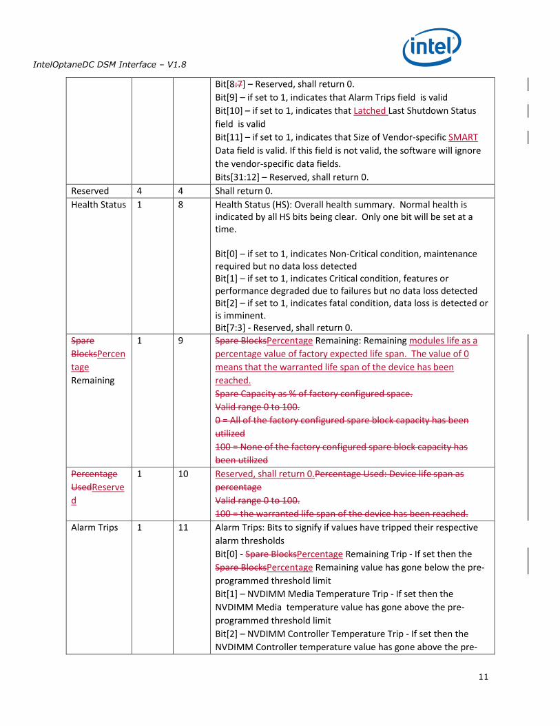
Bit[8:7] – Reserved, shall return 0.
Bit[9] – if set to 1, indicates that Alarm Trips field is valid
Bit[10] – if set to 1, indicates that Latched Last Shutdown Status
field is valid
Bit[11] – if set to 1, indicates that Size of Vendor-specific SMART
Data field is valid. If this field is not valid, the software will ignore
the vendor-specific data fields.
Bits[31:12] – Reserved, shall return 0.
Reserved 4 4 Shall return 0.
Health Status 1 8 Health Status (HS): Overall health summary. Normal health is indicated by all HS bits being clear. Only one bit will be set at a time. Bit[0] – if set to 1, indicates Non-Critical condition, maintenance required but no data loss detected Bit[1] – if set to 1, indicates Critical condition, features or performance degraded due to failures but no data loss detected Bit[2] – if set to 1, indicates fatal condition, data loss is detected or is imminent. Bit[7:3] - Reserved, shall return 0.
Spare
BlocksPercen
tage
Remaining
1 9 Spare BlocksPercentage Remaining: Remaining modules life as a
percentage value of factory expected life span. The value of 0
means that the warranted life span of the device has been
reached.
Spare Capacity as % of factory configured space.
Valid range 0 to 100.
0 = All of the factory configured spare block capacity has been
utilized
100 = None of the factory configured spare block capacity has
been utilized
Percentage
UsedReserve
d
1 10 Reserved, shall return 0.Percentage Used: Device life span as
percentage
Valid range 0 to 100.
100 = the warranted life span of the device has been reached.
Alarm Trips 1 11 Alarm Trips: Bits to signify if values have tripped their respective
alarm thresholds
Bit[0] - Spare BlocksPercentage Remaining Trip - If set then the
Spare BlocksPercentage Remaining value has gone below the pre-
programmed threshold limit
Bit[1] – NVDIMM Media Temperature Trip - If set then the
NVDIMM Media temperature value has gone above the pre-
programmed threshold limit
Bit[2] – NVDIMM Controller Temperature Trip - If set then the
NVDIMM Controller temperature value has gone above the pre-
IntelOptaneDC DSM Interface – V1.8
12
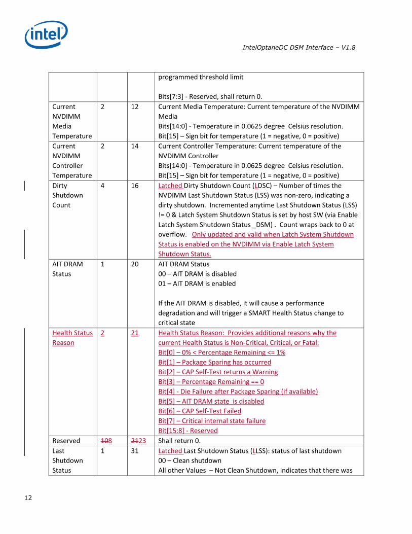
programmed threshold limit
Bits[7:3] - Reserved, shall return 0.
Current
NVDIMM
Media
Temperature
2 12 Current Media Temperature: Current temperature of the NVDIMM
Media
Bits[14:0] - Temperature in 0.0625 degree Celsius resolution.
Bit[15] – Sign bit for temperature (1 = negative, 0 = positive)
Current
NVDIMM
Controller
Temperature
2 14 Current Controller Temperature: Current temperature of the
NVDIMM Controller
Bits[14:0] - Temperature in 0.0625 degree Celsius resolution.
Bit[15] – Sign bit for temperature (1 = negative, 0 = positive)
Dirty
Shutdown
Count
4 16 Latched Dirty Shutdown Count (LDSC) – Number of times the
NVDIMM Last Shutdown Status (LSS) was non-zero, indicating a
dirty shutdown. Incremented anytime Last Shutdown Status (LSS)
!= 0 & Latch System Shutdown Status is set by host SW (via Enable
Latch System Shutdown Status _DSM) . Count wraps back to 0 at
overflow. Only updated and valid when Latch System Shutdown
Status is enabled on the NVDIMM via Enable Latch System
Shutdown Status.
AIT DRAM
Status
1 20 AIT DRAM Status
00 – AIT DRAM is disabled
01 – AIT DRAM is enabled
If the AIT DRAM is disabled, it will cause a performance
degradation and will trigger a SMART Health Status change to
critical state
Health Status
Reason
2 21 Health Status Reason: Provides additional reasons why the
current Health Status is Non-Critical, Critical, or Fatal:
Bit[0] – 0% < Percentage Remaining <= 1%
Bit[1] – Package Sparing has occurred
Bit[2] – CAP Self-Test returns a Warning
Bit[3] – Percentage Remaining == 0
Bit[4] - Die Failure after Package Sparing (if available)
Bit[5] – AIT DRAM state is disabled
Bit[6] – CAP Self-Test Failed
Bit[7] – Critical internal state failure
Bit[15:8] - Reserved
Reserved 108 2123 Shall return 0.
Last
Shutdown
Status
1 31 Latched Last Shutdown Status (LLSS): status of last shutdown
00 – Clean shutdown
All other Values – Not Clean Shutdown, indicates that there was
IntelOptaneDC DSM Interface – V1.8
13
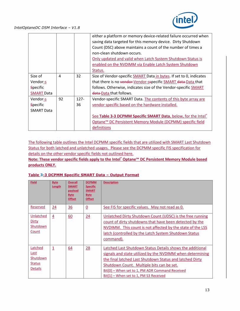
either a platform or memory device-related failure occurred when
saving data targeted for this memory device. Dirty Shutdown
Count (DSC) above maintains a count of the number of times a
non-clean shutdown occurs.
Only updated and valid when Latch System Shutdown Status is
enabled on the NVDIMM via Enable Latch System Shutdown
Status.
Size of
Vendor-s
Specific
SMART Data
4 32 Size of Vendor-specific SMART Data in bytes. If set to 0, indicates
that there is no vendor Vendor-sspecific SMART data Data that
follows. Otherwise, indicates size of the Vendor-specific SMART
data Data that follows.
Vendor-s
Specific
SMART Data
92 127-
36
Vendor-specific SMART Data. The contents of this byte array are
vendor specific based on the hardware installed.
See Table 3-3 DCPMM Specific SMART Data, below, for the Intel®
Optane™ DC Persistent Memory Module (DCPMM) specific field
definitions
The following table outlines the Intel DCPMM specific fields that are utilized with SMART Last Shutdown
Status for both latched and unlatched usages. Please see the DCPMM specific FIS specification for
details on the other vendor specific fields not outlined here.
Note: These vendor specific fields apply to the Intel® Optane™ DC Persistent Memory Module based
products ONLY.
Table 3-3 DCPMM Specific SMART Data – Output Format
Field Byte
Length
Overall
SMART
payload
Byte
Offset
DCPMM
Specific
SMART
Byte
Offset
Description
Reserved 24 36 0 See FIS for specific values. May not read as 0.
Unlatched
Dirty
Shutdown
Count
4 60 24 Unlatched Dirty Shutdown Count (UDSC) is the free running
count of dirty shutdowns that have been detected by the
NVDIMM. This count is not affected by the state of the LSS
latch (controlled by the Latch System Shutdown Status
command).
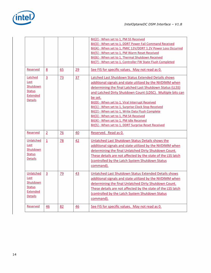
Latched
Last
Shutdown
Status
Details
1 64 28 Latched Last Shutdown Status Details shows the additional
signals and state utilized by the NVDIMM when determining
the final latched Last Shutdown Status and latched Dirty
Shutdown Count. Multiple bits can be set. Bit[0] – When set to 1, PM ADR Command Received
Bit[1] – When set to 1, PM S3 Received
IntelOptaneDC DSM Interface – V1.8
14
Bit[2] - When set to 1, PM S5 Received
Bit[3] - When set to 1, DDRT Power Fail Command Received
Bit[4] - When set to 1, PMIC 12V/DDRT 1.2V Power Loss Occurred
Bit[5] - When set to 1, PM Warm Reset Received
Bit[6] - When set to 1, Thermal Shutdown Received
Bit[7] - When set to 1, Controller FW State Flush Completed
Reserved 8 65 29 See FIS for specific values. May not read as 0.
Latched
Last
Shutdown
Status
Extended
Details
3 73 37 Latched Last Shutdown Status Extended Details shows
additional signals and state utilized by the NVDIMM when
determining the final Latched Last Shutdown Status (LLSS)
and Latched Dirty Shutdown Count (LDSC). Multiple bits can
be set. Bit[0] - When set to 1, Viral Interrupt Received
Bit[1] - When set to 1, Surprise Clock Stop Received
Bit[2] - When set to 1, Write Data Flush Complete
Bit[3] - When set to 1, PM S4 Received
Bit[4] - When set to 1, PM Idle Received
Bit[5] - When set to 1, DDRT Surprise Reset Received
Reserved 2 76 40 Reserved. Read as 0.
Unlatched
Last
Shutdown
Status
Details
1 78 42 Unlatched Last Shutdown Status Details shows the
additional signals and state utilized by the NVDIMM when
determining the final Unlatched Dirty Shutdown Count.
These details are not affected by the state of the LSS latch
(controlled by the Latch System Shutdown Status
command).
Unlatched
Last
Shutdown
Status
Extended
Details
3 79 43 Unlatched Last Shutdown Status Extended Details shows
additional signals and state utilized by the NVDIMM when
determining the final Unlatched Dirty Shutdown Count.
These details are not affected by the state of the LSS latch
(controlled by the Latch System Shutdown Status
command).
Reserved 46 82 46 See FIS for specific values. May not read as 0.
IntelOptaneDC DSM Interface – V1.8
15
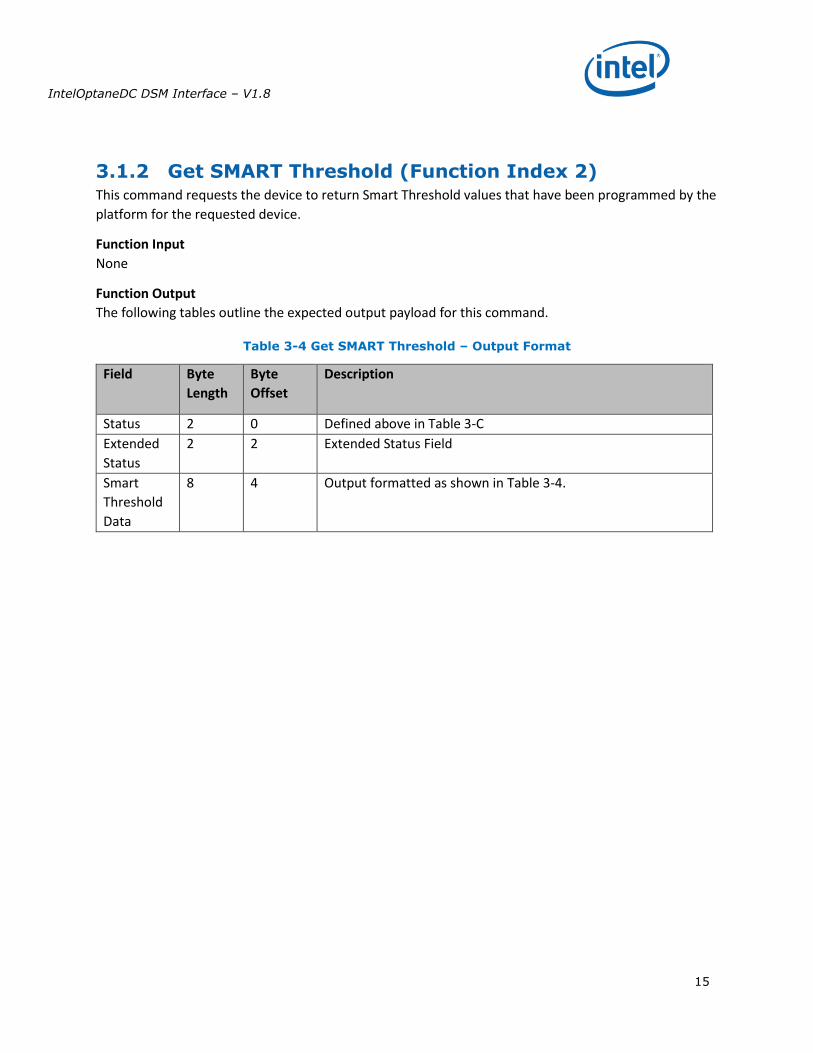
3.1.2 Get SMART Threshold (Function Index 2) This command requests the device to return Smart Threshold values that have been programmed by the
platform for the requested device.
Function Input
None
Function Output
The following tables outline the expected output payload for this command.
Table 3-4 Get SMART Threshold – Output Format
Field Byte
Length
Byte
Offset
Description
Status 2 0 Defined above in Table 3-C
Extended
Status
2 2 Extended Status Field
Smart
Threshold
Data
8 4 Output formatted as shown in Table 3-4.
IntelOptaneDC DSM Interface – V1.8
16
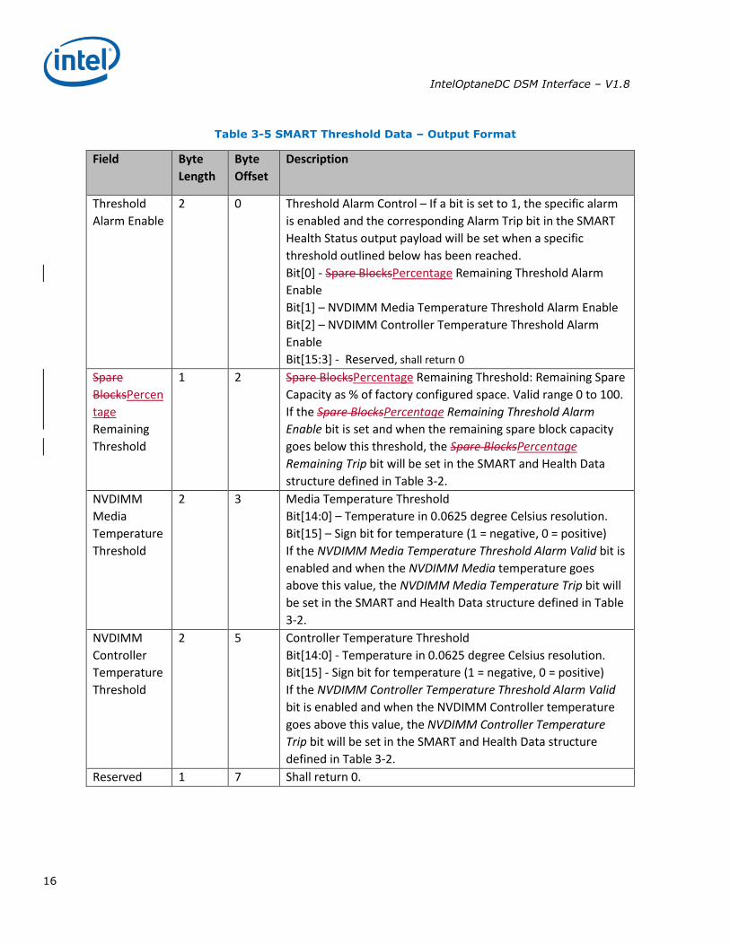
Table 3-5 SMART Threshold Data – Output Format
Field Byte
Length
Byte
Offset
Description
Threshold
Alarm Enable
2 0 Threshold Alarm Control – If a bit is set to 1, the specific alarm
is enabled and the corresponding Alarm Trip bit in the SMART
Health Status output payload will be set when a specific
threshold outlined below has been reached.
Bit[0] - Spare BlocksPercentage Remaining Threshold Alarm
Enable
Bit[1] – NVDIMM Media Temperature Threshold Alarm Enable
Bit[2] – NVDIMM Controller Temperature Threshold Alarm
Enable
Bit[15:3] - Reserved, shall return 0
Spare
BlocksPercen
tage
Remaining
Threshold
1 2 Spare BlocksPercentage Remaining Threshold: Remaining Spare
Capacity as % of factory configured space. Valid range 0 to 100.
If the Spare BlocksPercentage Remaining Threshold Alarm
Enable bit is set and when the remaining spare block capacity
goes below this threshold, the Spare BlocksPercentage
Remaining Trip bit will be set in the SMART and Health Data
structure defined in Table 3-2.
NVDIMM
Media
Temperature
Threshold
2 3 Media Temperature Threshold
Bit[14:0] – Temperature in 0.0625 degree Celsius resolution.
Bit[15] – Sign bit for temperature (1 = negative, 0 = positive)
If the NVDIMM Media Temperature Threshold Alarm Valid bit is
enabled and when the NVDIMM Media temperature goes
above this value, the NVDIMM Media Temperature Trip bit will
be set in the SMART and Health Data structure defined in Table
3-2.
NVDIMM
Controller
Temperature
Threshold
2 5 Controller Temperature Threshold
Bit[14:0] - Temperature in 0.0625 degree Celsius resolution.
Bit[15] - Sign bit for temperature (1 = negative, 0 = positive)
If the NVDIMM Controller Temperature Threshold Alarm Valid
bit is enabled and when the NVDIMM Controller temperature
goes above this value, the NVDIMM Controller Temperature
Trip bit will be set in the SMART and Health Data structure
defined in Table 3-2.
Reserved 1 7 Shall return 0.

IntelOptaneDC DSM Interface – V1.8
17
3.1.3 Set SMART Threshold (Function Index 17) This command requests the device to simultaneously enable specific SMART Threshold Alarm Triggers
and set the SMART Threshold Alarm Trigger values for the device. Parameter values are verified first
before any enable/disable state or threshold values are updated.
Function Input The following tables outline the expected input payload for this command.
Table 3-6 Set SMART Threshold – Input Format
Field Byte
Length
Byte
Offset
Description
Threshold
Alarm Enable
2 0 Threshold Alarm Control - If a bit is set to 1, the specific alarm is
enabled and the corresponding Alarm Trip bit in the SMART
Health Status output payload will be set when a specific threshold
outlined below has been reached.
Bit[0] - Spare BlocksPercentage Remaining Threshold Alarm
Enable
Bit[1] – NVDIMM Media Temperature Threshold Alarm Enable
Bit[2] – NVDIMM Controller Temperature Threshold Alarm Enable
Bit[15:3] - Reserved, shall be 0
Spare
BlocksPercen
tage
Remaining
Threshold
1 2 Percentage Remaining Remaining Spare Capacity Alarm - A % of
factory configured spare blocks. Values 0 & 100 are not valid and
will result in an error.
If the Spare BlocksPercentage Remaining Threshold Alarm Enable
bit is set and when the spare block capacity goes below this
threshold, the Spare BlocksPercentage Remaining Trip bit will be
set in the SMART and Health Data structure defined in Table 3-2.
This field is ignored if the Spare BlocksPercentage Remaining
Threshold Alarm Enable bit above is cleared to 0.
NVDIMM
Media
Temperature
Threshold
2 3 Media Temperature Alarm
Bit[14:0] – Temperature in 0.0625 degree Celsius resolution.
Bit[15] – Sign bit for temperature (1 = negative, 0 = positive)
If the NVDIMM Media Temperature Threshold Alarm Valid Enable
bit is enabled and when the NVDIMM Media temperature goes
above this value, the NVDIMM Media Temperature Trip bit will be
set in the SMART and Health Data structure defined in Table 3-2.
This field is ignored if the NVDIMM Media Temperature Threshold
Alarm Enable bit above is cleared to 0.
NVDIMM
Controller
Temperature
Threshold
2 5 Control Temperature Alarm
Bit[14:0] - Temperature in 0.0625 degree Celsius resolution.
Bit[15] - Sign bit for temperature (1 = negative, 0 = positive)
IntelOptaneDC DSM Interface – V1.8
18
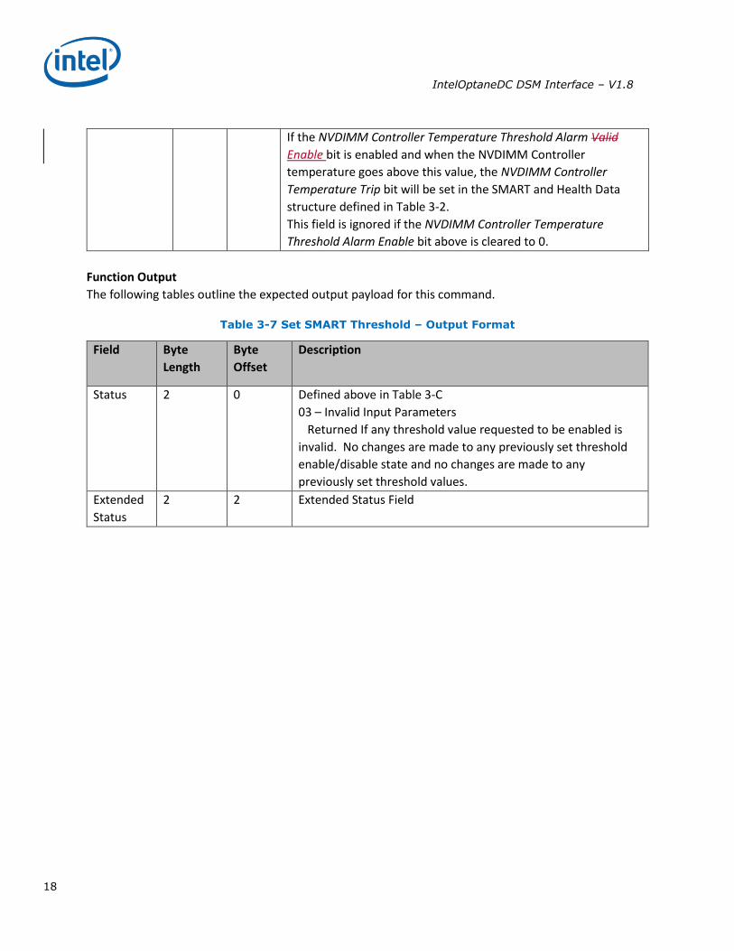
If the NVDIMM Controller Temperature Threshold Alarm Valid
Enable bit is enabled and when the NVDIMM Controller
temperature goes above this value, the NVDIMM Controller
Temperature Trip bit will be set in the SMART and Health Data
structure defined in Table 3-2.
This field is ignored if the NVDIMM Controller Temperature
Threshold Alarm Enable bit above is cleared to 0.
Function Output
The following tables outline the expected output payload for this command.
Table 3-7 Set SMART Threshold – Output Format
Field Byte
Length
Byte
Offset
Description
Status 2 0 Defined above in Table 3-C
03 – Invalid Input Parameters
Returned If any threshold value requested to be enabled is
invalid. No changes are made to any previously set threshold
enable/disable state and no changes are made to any
previously set threshold values.
Extended
Status
2 2 Extended Status Field
IntelOptaneDC DSM Interface – V1.8
19
Command Effect Log
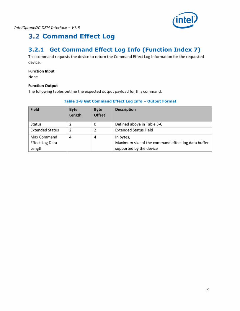
3.2.1 Get Command Effect Log Info (Function Index 7) This command requests the device to return the Command Effect Log Information for the requested
device.
Function Input
None
Function Output
The following tables outline the expected output payload for this command.
Table 3-8 Get Command Effect Log Info – Output Format
Field Byte
Length
Byte
Offset
Description
Status 2 0 Defined above in Table 3-C
Extended Status 2 2 Extended Status Field
Max Command
Effect Log Data
Length
4 4 In bytes,
Maximum size of the command effect log data buffer
supported by the device
IntelOptaneDC DSM Interface – V1.8
20
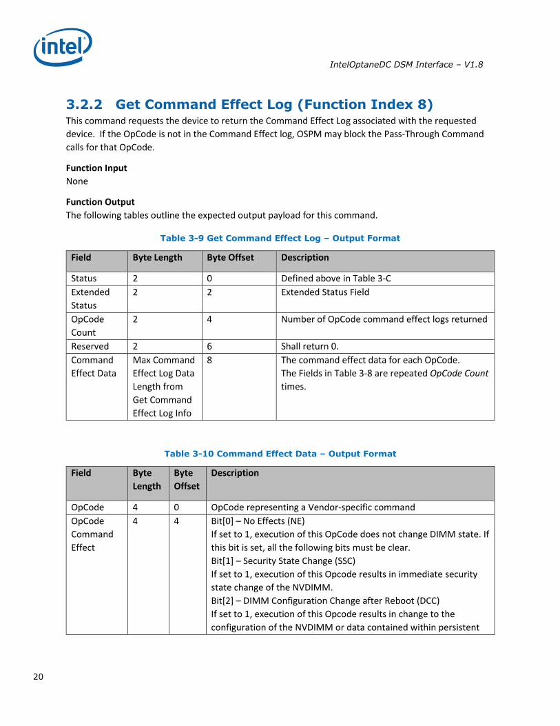
3.2.2 Get Command Effect Log (Function Index 8) This command requests the device to return the Command Effect Log associated with the requested
device. If the OpCode is not in the Command Effect log, OSPM may block the Pass-Through Command
calls for that OpCode.
Function Input
None
Function Output
The following tables outline the expected output payload for this command.
Table 3-9 Get Command Effect Log – Output Format
Field Byte Length Byte Offset Description
Status 2 0 Defined above in Table 3-C
Extended
Status
2 2 Extended Status Field
OpCode
Count
2 4 Number of OpCode command effect logs returned
Reserved 2 6 Shall return 0.
Command
Effect Data
Max Command
Effect Log Data
Length from
Get Command
Effect Log Info
8 The command effect data for each OpCode.
The Fields in Table 3-8 are repeated OpCode Count
times.
Table 3-10 Command Effect Data – Output Format
Field Byte
Length
Byte
Offset
Description
OpCode 4 0 OpCode representing a Vendor-specific command
OpCode
Command
Effect
4 4 Bit[0] – No Effects (NE)
If set to 1, execution of this OpCode does not change DIMM state. If
this bit is set, all the following bits must be clear.
Bit[1] – Security State Change (SSC)
If set to 1, execution of this Opcode results in immediate security
state change of the NVDIMM.
Bit[2] – DIMM Configuration Change after Reboot (DCC)
If set to 1, execution of this Opcode results in change to the
configuration of the NVDIMM or data contained within persistent
IntelOptaneDC DSM Interface – V1.8
21
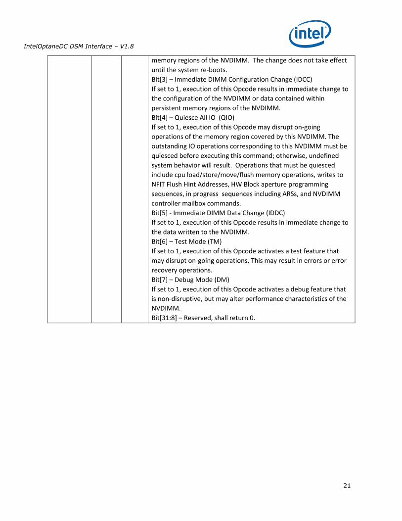
memory regions of the NVDIMM. The change does not take effect
until the system re-boots.
Bit[3] – Immediate DIMM Configuration Change (IDCC)
If set to 1, execution of this Opcode results in immediate change to
the configuration of the NVDIMM or data contained within
persistent memory regions of the NVDIMM.
Bit[4] – Quiesce All IO (QIO)
If set to 1, execution of this Opcode may disrupt on-going
operations of the memory region covered by this NVDIMM. The
outstanding IO operations corresponding to this NVDIMM must be
quiesced before executing this command; otherwise, undefined
system behavior will result. Operations that must be quiesced
include cpu load/store/move/flush memory operations, writes to
NFIT Flush Hint Addresses, HW Block aperture programming
sequences, in progress sequences including ARSs, and NVDIMM
controller mailbox commands.
Bit[5] - Immediate DIMM Data Change (IDDC)
If set to 1, execution of this Opcode results in immediate change to
the data written to the NVDIMM.
Bit[6] – Test Mode (TM)
If set to 1, execution of this Opcode activates a test feature that
may disrupt on-going operations. This may result in errors or error
recovery operations.
Bit[7] – Debug Mode (DM)
If set to 1, execution of this Opcode activates a debug feature that
is non-disruptive, but may alter performance characteristics of the
NVDIMM.
Bit[31:8] – Reserved, shall return 0.
IntelOptaneDC DSM Interface – V1.8
22
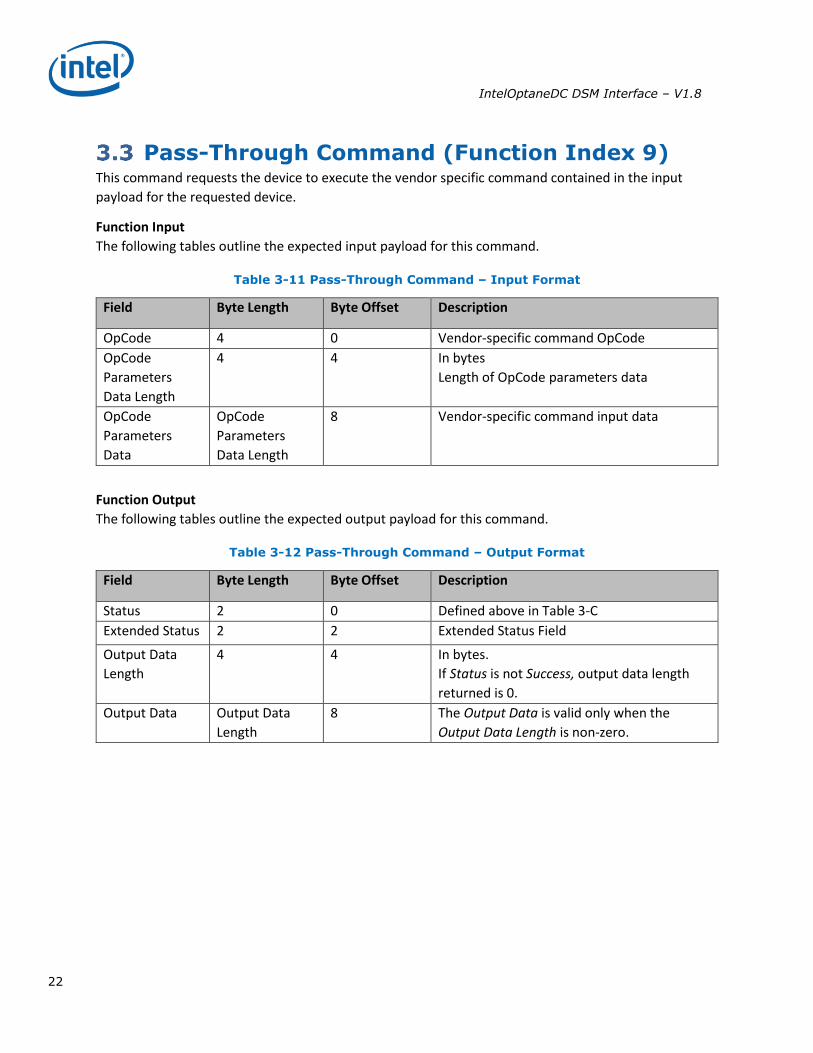
Pass-Through Command (Function Index 9) This command requests the device to execute the vendor specific command contained in the input
payload for the requested device.
Function Input
The following tables outline the expected input payload for this command.
Table 3-11 Pass-Through Command – Input Format
Field Byte Length Byte Offset Description
OpCode 4 0 Vendor-specific command OpCode
OpCode
Parameters
Data Length
4 4 In bytes
Length of OpCode parameters data
OpCode
Parameters
Data
OpCode
Parameters
Data Length
8 Vendor-specific command input data
Function Output
The following tables outline the expected output payload for this command.
Table 3-12 Pass-Through Command – Output Format
Field Byte Length Byte Offset Description
Status 2 0 Defined above in Table 3-C
Extended Status 2 2 Extended Status Field
Output Data
Length
4 4 In bytes.
If Status is not Success, output data length
returned is 0.
Output Data Output Data
Length
8 The Output Data is valid only when the
Output Data Length is non-zero.
IntelOptaneDC DSM Interface – V1.8
23
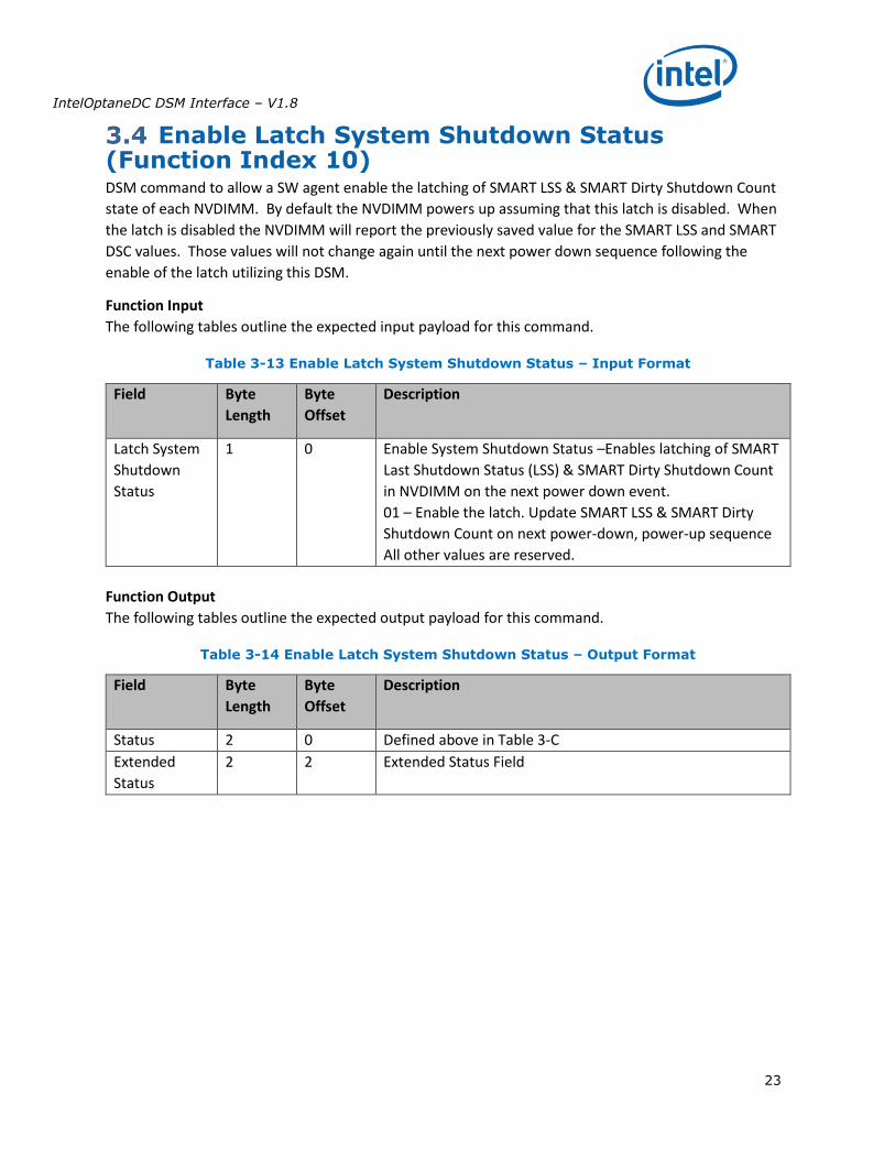
Enable Latch System Shutdown Status (Function Index 10) DSM command to allow a SW agent enable the latching of SMART LSS & SMART Dirty Shutdown Count
state of each NVDIMM. By default the NVDIMM powers up assuming that this latch is disabled. When
the latch is disabled the NVDIMM will report the previously saved value for the SMART LSS and SMART
DSC values. Those values will not change again until the next power down sequence following the
enable of the latch utilizing this DSM.
Function Input
The following tables outline the expected input payload for this command.
Table 3-13 Enable Latch System Shutdown Status – Input Format
Field Byte
Length
Byte
Offset
Description
Latch System
Shutdown
Status
1 0 Enable System Shutdown Status –Enables latching of SMART
Last Shutdown Status (LSS) & SMART Dirty Shutdown Count
in NVDIMM on the next power down event.
01 – Enable the latch. Update SMART LSS & SMART Dirty
Shutdown Count on next power-down, power-up sequence
All other values are reserved.
Function Output
The following tables outline the expected output payload for this command.
Table 3-14 Enable Latch System Shutdown Status – Output Format
Field Byte
Length
Byte
Offset
Description
Status 2 0 Defined above in Table 3-C
Extended
Status
2 2 Extended Status Field

IntelOptaneDC DSM Interface – V1.8
24
Get Supported Modes (Function Index 11) This command requests the platform to return details about the supported Modes of the NVDIMM
Interface implementation.
Function Input
None
Function Output
The following tables outline the expected output payload for this command.
Table 3-15 Get Supported Modes – Output Format
Field Byte Length Byte Offset Description
Status 2 0 Defined above in Table 3-C
Extended
Status
2 2 Extended Status Field
Supported
Modes
2 4 The list of the DIMMs capabilities:
Bit[0] – Memory Mode supported
Bit[1] – PMEM Mode supported
Bit[2] – Block Aperture Mode supported
Bit[15:3] – Reserved, shall return 0.
IntelOptaneDC DSM Interface – V1.8
25
NVDIMM FW Download
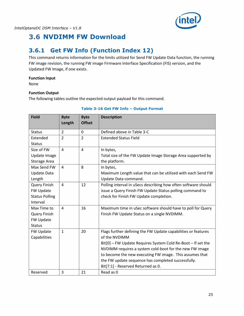
3.6.1 Get FW Info (Function Index 12) This command returns information for the limits utilized for Send FW Update Data function, the running
FW image revision, the running FW image Firmware Interface Specification (FIS) version, and the
Updated FW Image, if one exists.
Function Input
None
Function Output
The following tables outline the expected output payload for this command.
Table 3-16 Get FW Info – Output Format
Field Byte
Length
Byte
Offset
Description
Status 2 0 Defined above in Table 3-C
Extended
Status
2 2 Extended Status Field
Size of FW
Update Image
Storage Area
4 4 In bytes,
Total size of the FW Update Image Storage Area supported by
the platform.
Max Send FW
Update Data
Length
4 8 In bytes,
Maximum Length value that can be utilized with each Send FW
Update Data command.
Query Finish
FW Update
Status Polling
Interval
4 12 Polling interval in uSecs describing how often software should
issue a Query Finish FW Update Status polling command to
check for Finish FW Update completion.
Max Time to
Query Finish
FW Update
Status
4 16 Maximum time in uSec software should have to poll for Query
Finish FW Update Status on a single NVDIMM.
FW Update
Capabilities
1 20 Flags further defining the FW Update capabilities or features
of the NVDIMM
Bit[0] – FW Update Requires System Cold Re-Boot – If set the
NVDIMM requires a system cold-boot for the new FW image
to become the new executing FW image. This assumes that
the FW update sequence has completed successfully.
Bit[7:1] - Reserved Returned as 0.
Reserved 3 21 Read as 0
IntelOptaneDC DSM Interface – V1.8
26
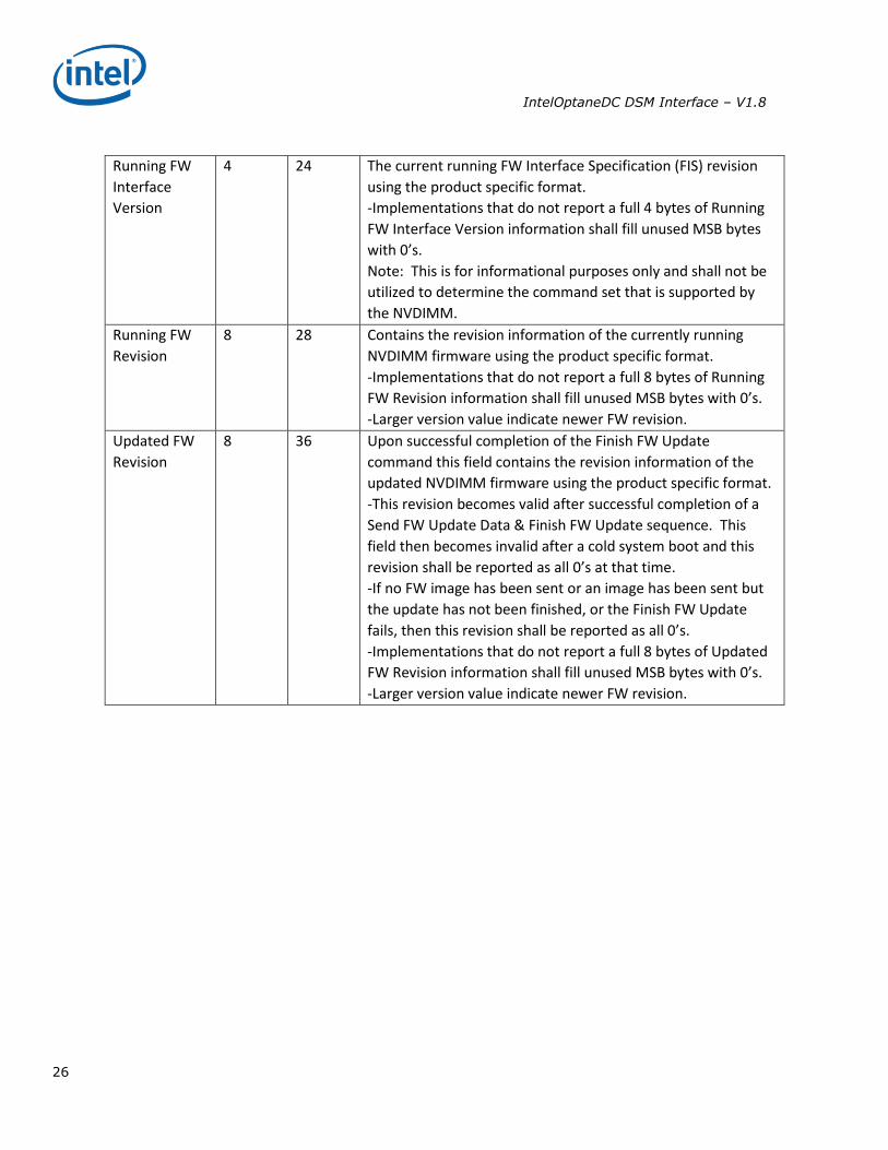
Running FW
Interface
Version
4 24 The current running FW Interface Specification (FIS) revision
using the product specific format.
-Implementations that do not report a full 4 bytes of Running
FW Interface Version information shall fill unused MSB bytes
with 0’s.
Note: This is for informational purposes only and shall not be
utilized to determine the command set that is supported by
the NVDIMM.
Running FW
Revision
8 28
Contains the revision information of the currently running
NVDIMM firmware using the product specific format.
-Implementations that do not report a full 8 bytes of Running
FW Revision information shall fill unused MSB bytes with 0’s.
-Larger version value indicate newer FW revision.
Updated FW
Revision
8 36
Upon successful completion of the Finish FW Update
command this field contains the revision information of the
updated NVDIMM firmware using the product specific format.
-This revision becomes valid after successful completion of a
Send FW Update Data & Finish FW Update sequence. This
field then becomes invalid after a cold system boot and this
revision shall be reported as all 0’s at that time.
-If no FW image has been sent or an image has been sent but
the update has not been finished, or the Finish FW Update
fails, then this revision shall be reported as all 0’s.
-Implementations that do not report a full 8 bytes of Updated
FW Revision information shall fill unused MSB bytes with 0’s.
-Larger version value indicate newer FW revision.
IntelOptaneDC DSM Interface – V1.8
27
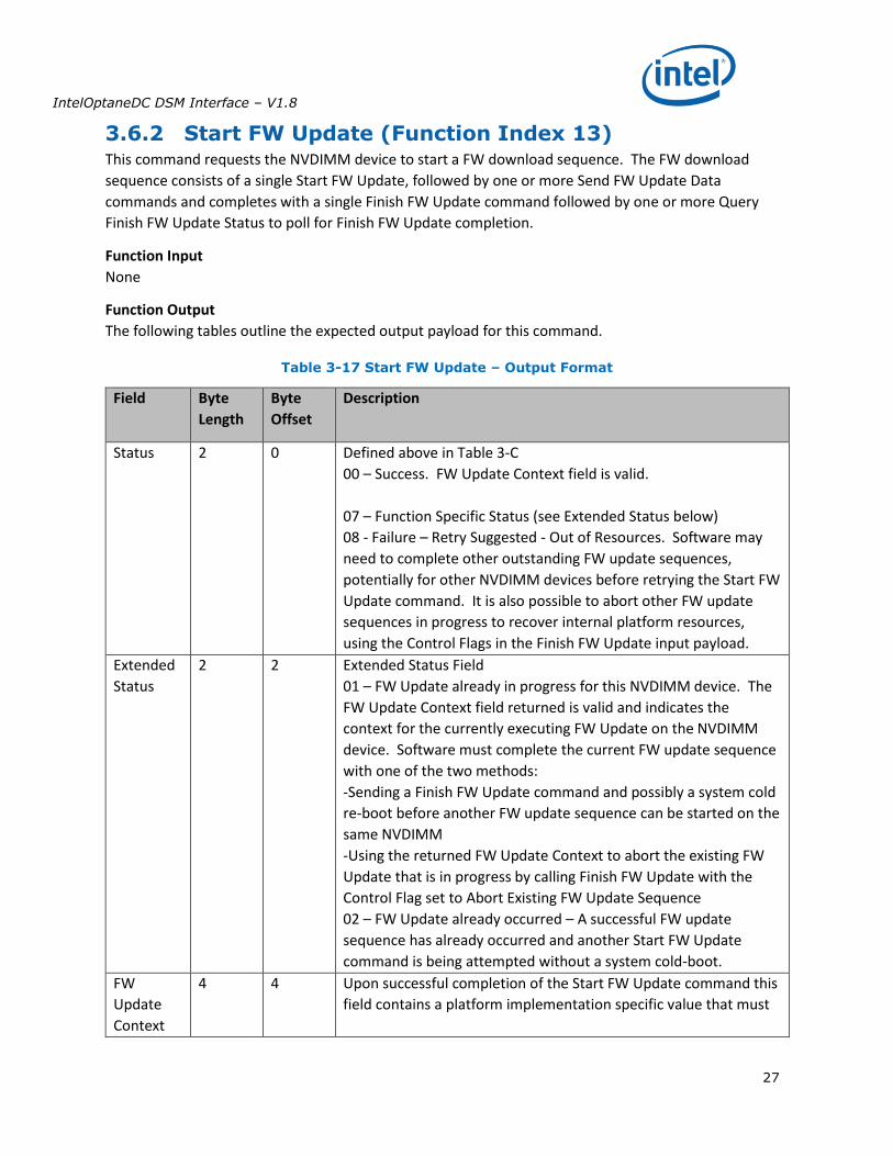
3.6.2 Start FW Update (Function Index 13) This command requests the NVDIMM device to start a FW download sequence. The FW download
sequence consists of a single Start FW Update, followed by one or more Send FW Update Data
commands and completes with a single Finish FW Update command followed by one or more Query
Finish FW Update Status to poll for Finish FW Update completion.
Function Input
None
Function Output
The following tables outline the expected output payload for this command.
Table 3-17 Start FW Update – Output Format
Field Byte
Length
Byte
Offset
Description
Status 2 0 Defined above in Table 3-C
00 – Success. FW Update Context field is valid.
07 – Function Specific Status (see Extended Status below)
08 - Failure – Retry Suggested - Out of Resources. Software may
need to complete other outstanding FW update sequences,
potentially for other NVDIMM devices before retrying the Start FW
Update command. It is also possible to abort other FW update
sequences in progress to recover internal platform resources,
using the Control Flags in the Finish FW Update input payload.
Extended
Status
2 2 Extended Status Field
01 – FW Update already in progress for this NVDIMM device. The
FW Update Context field returned is valid and indicates the
context for the currently executing FW Update on the NVDIMM
device. Software must complete the current FW update sequence
with one of the two methods:
-Sending a Finish FW Update command and possibly a system cold
re-boot before another FW update sequence can be started on the
same NVDIMM
-Using the returned FW Update Context to abort the existing FW
Update that is in progress by calling Finish FW Update with the
Control Flag set to Abort Existing FW Update Sequence
02 – FW Update already occurred – A successful FW update
sequence has already occurred and another Start FW Update
command is being attempted without a system cold-boot.
FW
Update
Context
4 4
Upon successful completion of the Start FW Update command this
field contains a platform implementation specific value that must

IntelOptaneDC DSM Interface – V1.8
28
be passed as an input parameter to Send FW Update Data and
Finish FW Update commands.
IntelOptaneDC DSM Interface – V1.8
29
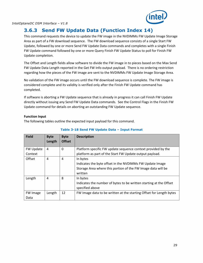
3.6.3 Send FW Update Data (Function Index 14) This command requests the device to update the FW image in the NVDIMMs FW Update Image Storage
Area as part of a FW download sequence. The FW download sequence consists of a single Start FW
Update, followed by one or more Send FW Update Data commands and completes with a single Finish
FW Update command followed by one or more Query Finish FW Update Status to poll for Finish FW
Update completion.
The Offset and Length fields allow software to divide the FW image in to pieces based on the Max Send
FW Update Data Length reported in the Get FW Info output payload. There is no ordering restriction
regarding how the pieces of the FW image are sent to the NVDIMMs FW Update Image Storage Area.
No validation of the FW image occurs until the FW download sequence is complete. The FW image is
considered complete and its validity is verified only after the Finish FW Update command has
completed.
If software is aborting a FW Update sequence that is already in progress it can call Finish FW Update
directly without issuing any Send FW Update Data commands. See the Control Flags in the Finish FW
Update command for details on aborting an outstanding FW Update sequence.
Function Input
The following tables outline the expected input payload for this command.
Table 3-18 Send FW Update Data – Input Format
Field Byte
Length
Byte
Offset
Description
FW Update
Context
4 0 Platform specific FW update sequence context provided by the
platform as part of the Start FW Update output payload.
Offset 4 4 In bytes
Indicates the byte offset in the NVDIMMs FW Update Image
Storage Area where this portion of the FW Image data will be
written
Length 4 8 In bytes
Indicates the number of bytes to be written starting at the Offset
specified above
FW Image
Data
Length 12 FW Image data to be written at the starting Offset for Length bytes
IntelOptaneDC DSM Interface – V1.8
30
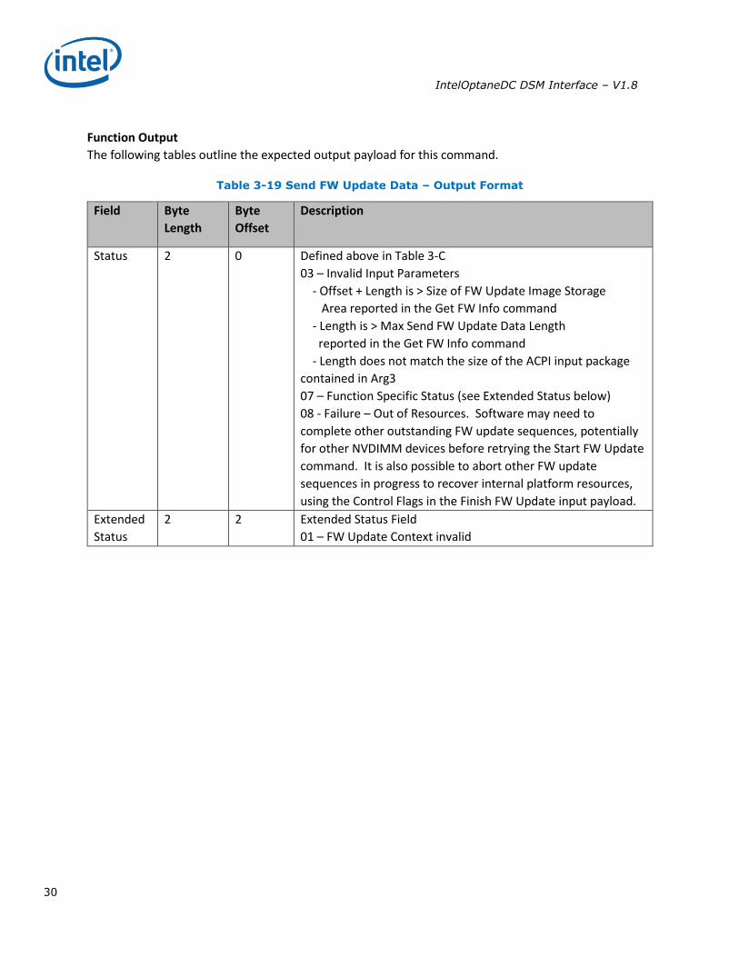
Function Output
The following tables outline the expected output payload for this command.
Table 3-19 Send FW Update Data – Output Format
Field Byte
Length
Byte
Offset
Description
Status 2 0 Defined above in Table 3-C
03 – Invalid Input Parameters
- Offset + Length is > Size of FW Update Image Storage
Area reported in the Get FW Info command
- Length is > Max Send FW Update Data Length
reported in the Get FW Info command
- Length does not match the size of the ACPI input package
contained in Arg3
07 – Function Specific Status (see Extended Status below)
08 - Failure – Out of Resources. Software may need to
complete other outstanding FW update sequences, potentially
for other NVDIMM devices before retrying the Start FW Update
command. It is also possible to abort other FW update
sequences in progress to recover internal platform resources,
using the Control Flags in the Finish FW Update input payload.
Extended
Status
2 2 Extended Status Field
01 – FW Update Context invalid
IntelOptaneDC DSM Interface – V1.8
31
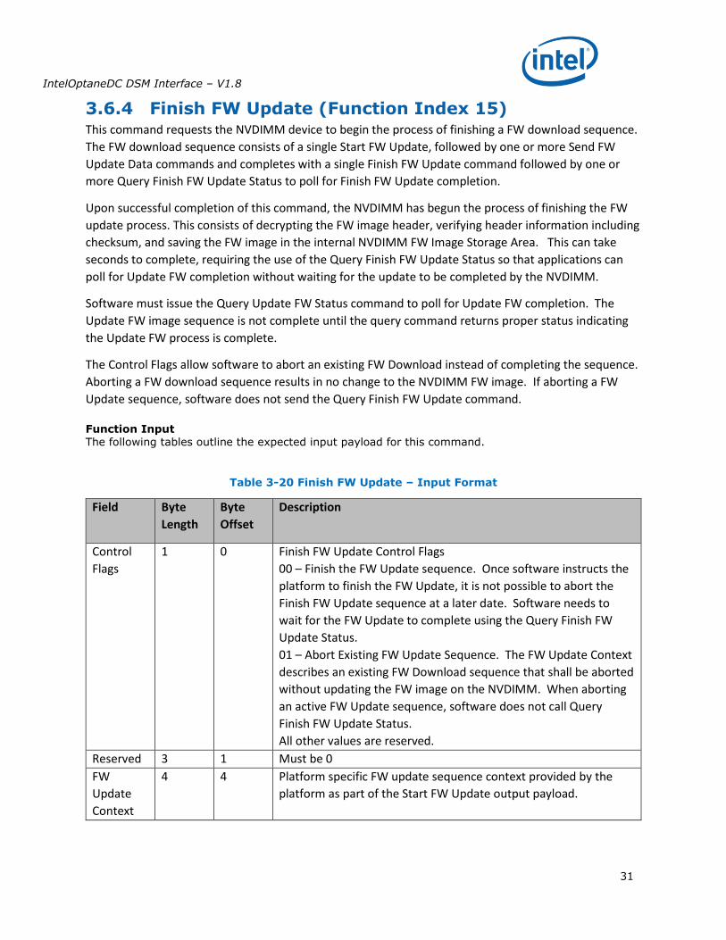
3.6.4 Finish FW Update (Function Index 15) This command requests the NVDIMM device to begin the process of finishing a FW download sequence.
The FW download sequence consists of a single Start FW Update, followed by one or more Send FW
Update Data commands and completes with a single Finish FW Update command followed by one or
more Query Finish FW Update Status to poll for Finish FW Update completion.
Upon successful completion of this command, the NVDIMM has begun the process of finishing the FW
update process. This consists of decrypting the FW image header, verifying header information including
checksum, and saving the FW image in the internal NVDIMM FW Image Storage Area. This can take
seconds to complete, requiring the use of the Query Finish FW Update Status so that applications can
poll for Update FW completion without waiting for the update to be completed by the NVDIMM.
Software must issue the Query Update FW Status command to poll for Update FW completion. The
Update FW image sequence is not complete until the query command returns proper status indicating
the Update FW process is complete.
The Control Flags allow software to abort an existing FW Download instead of completing the sequence.
Aborting a FW download sequence results in no change to the NVDIMM FW image. If aborting a FW
Update sequence, software does not send the Query Finish FW Update command.
Function Input The following tables outline the expected input payload for this command.
Table 3-20 Finish FW Update – Input Format
Field Byte
Length
Byte
Offset
Description
Control
Flags
1 0 Finish FW Update Control Flags
00 – Finish the FW Update sequence. Once software instructs the
platform to finish the FW Update, it is not possible to abort the
Finish FW Update sequence at a later date. Software needs to
wait for the FW Update to complete using the Query Finish FW
Update Status.
01 – Abort Existing FW Update Sequence. The FW Update Context
describes an existing FW Download sequence that shall be aborted
without updating the FW image on the NVDIMM. When aborting
an active FW Update sequence, software does not call Query
Finish FW Update Status.
All other values are reserved.
Reserved 3 1 Must be 0
FW
Update
Context
4 4 Platform specific FW update sequence context provided by the
platform as part of the Start FW Update output payload.
IntelOptaneDC DSM Interface – V1.8
32
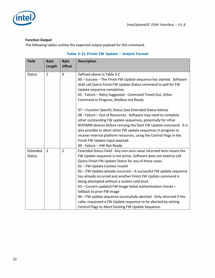
Function Output
The following tables outline the expected output payload for this command.
Table 3-21 Finish FW Update – Output Format
Field Byte
Length
Byte
Offset
Description
Status 2 0 Defined above in Table 3-C
00 – Success – The Finish FW Update sequence has started. Software
shall call Query Finish FW Update Status command to poll for FW
Update sequence completion
05 - Failure – Retry Suggested - Command Timed Out, Other
Command In Progress, Mailbox not Ready
07 – Function Specific Status (see Extended Status below)
08 - Failure – Out of Resources. Software may need to complete
other outstanding FW update sequences, potentially for other
NVDIMM devices before retrying the Start FW Update command. It is
also possible to abort other FW update sequences in progress to
recover internal platform resources, using the Control Flags in the
Finish FW Update input payload.
09 - Failure – HW Not Ready
Extended
Status
2 2 Extended Status Field - Any non-zero value returned here means the
FW Update sequence is not active. Software does not need to call
Query Finish FW Update Status for any of these cases.
01 – FW Update Context invalid
02 – FW Update already occurred – A successful FW update sequence
has already occurred and another Finish FW Update command is
being attempted without a system cold-boot.
03 – Current updated FW Image failed authentication checks –
fallback to prior FW image
04 – FW update sequence successfully aborted. Only returned if the
caller requested a FW Update sequence to be aborted by setting
Control Flags to Abort Existing FW Update Sequence.
IntelOptaneDC DSM Interface – V1.8
33
3.6.5 Query Finish FW Update Status (Function Index 16) This command allows software to poll for completion of the FW download sequence. The FW download
sequence consists of a single Start FW Update, followed by one or more Send FW Update Data
commands and completes with a single Finish FW Update command followed by one or more Query
Finish FW Update Status to poll for Finish FW Update completion.
Finish FW Update consists of decrypting the FW image header, verifying header information including
checksum, and saving the FW image in the internal FW Image Storage Area. This can take seconds to
complete requiring the use of the Query Finish FW Update Status so that applications can poll for
completion without the BIOS blocking in SMM waiting for the update to be completed by the NVDIMM.
The Query Finish FW Update Status Polling Interval returned in the Get FW Info command specifies what
frequency software should utilize when polling for Finish FW Update completion using the Query Finish
FW Update Status command.
Upon successful completion of this command, the updated FW image will become the new executing
FW image on the next system cold re-boot, replacing the currently executing FW image.
Sending a Finish FW Update followed by one or more Query Finish FW Update Status commands
completes the FW download sequence and requests the NVDIMM to verify the Updated FW Image and
report the revision information for the Updated FW Image. If no updated FW image is sent or the
updated FW image is incomplete, Query Finish FW Update Status command will return an appropriate
error and the Updated FW Image Revision will be reported as all 0’s.
Only a single FW Update sequence can be handled per NVDIMM per system cold-boot sequence. Once
successful status is returned for Query Finish FW Update Status, the system must be go through a cold-
boot cycle before another FW Update sequence can be executed on that same NVDIMM. Multiple
NVDIMMs can have FW images updated and utilize a single system cold-boot to activate the new FW
image on all NVDIMMs.
Function Input The following tables outline the expected input payload for this command.
Table 3-22 Query Finish FW Update Status – Input Format
Field Byte
Length
Byte
Offset
Description
FW
Update
Context
4 0 Platform specific FW update sequence context provided by the
platform as part of the Start FW Update output payload.
IntelOptaneDC DSM Interface – V1.8
34
Function Output
The following tables outline the expected output payload for this command.
Table 3-23 Query Finish FW Update Status – Output Format
Field Byte
Length
Byte
Offset
Description
Status 2 0 Defined above in Table 3-C
00 – Success – The Update FW sequence has completed successfully.
Authentication checks passed. Updated FW Revision field is valid.
The Updated FW Image will be loaded on the next system cold-boot.
07 – Function Specific Status (see Extended Status below)
08 - The Finish FW Update sequence timed out
Extended
Status
2 2 Extended Status Field
01 – FW Update Context invalid
02 – FW Update in progress
03 – Current updated FW Image failed authentication checks –
fallback to prior FW image
04 – Sequencing Error – Query Finish FW Update Status called
without first calling Finish FW Update
Updated
FW
Revision
8 4
Upon successful completion of the Finish FW Update command this
field contains the revision information of the updated NVDIMM
firmware using the product specific format.
-This becomes valid after successful completion of a Send FW Update
Data & Finish FW Update sequence. This field then becomes invalid
after a cold system re-boot.
-If no FW image has been updated or the updated FW image is
invalid, or the Finish FW Update fails, then this revision shall be
reported as all 0’s.
-Implementations that do not report a full 8 bytes of Updated
-FW Revision information shall fill unused MSB bytes with 0’s.
-Larger version value indicates newer FW revision.
IntelOptaneDC DSM Interface – V1.8
35
Inject Error (Function Index 18) Inject NVDIMM specific errors not covered by the ACPI ARS Error Inject function. None of the injected
errors are persistent across power cycles or re-boots unless otherwise stated below. An error will stay
injected until disabled using this command or the system is restarted, unless otherwise stated below.
Function Input
The following tables outline the expected input payload for this command.
Table 3-24 Inject Error - Input Format
Field Byte
Length
Byte
Offset
Description
Error Inject
Validity Flags
8 0 Valid Fields – if the corresponding validation flag is not set in this
field, it is indication to software that the corresponding field is
not valid and must not be interpreted.
Bit[0] – if set to 1, indicates that all Media Temperature Error
Inject fields are valid
Bit[1] – if set to 1, indicates that all Spare BlocksPercentage
Remaining Trigger fields are valid
Bit[2] – if set to 1, indicates that all Fatal Error Trigger fields are
valid
Bit[3] – if set to 1, indicates that all Dirty Shutdown Error Trigger
fields are valid
Bit[63:4] – Reserved, shall be 0
Media
Temperature
Error Inject
3 8 Media Temperature Error Inject fields - This will override the
NVDIMM from reading the actual temperature of the media
device and spoof a media temperature reading of the injected
value instead.
Byte[0]
Bit[0] – Enable
If 0, injecting Media Temperature Errors is disabled.
If 1, the Media Temperature specified will be injected.
Bit[7:1] - Reserved, shall be 0.
Byte[2:1] - Media Temperature to Inject
Bit[14:0] – Temperature in Celsius with 0.0625 resolution
Bit[15] – Sign Bit, if 1 the Temperature is negative, if 0 the
temperature is positive
Note: Although actions taken due to the Media Temperature
injected may cause adverse effects on the NVDIMM, including IO
throttling, the media temperature injected is an artificial
temperature and will not cause harm to the NVDIMM. If the
critical shutdown temperature, or higher, is injected, the
NVDIMM may shutdown in order to preserve the part and data.
IntelOptaneDC DSM Interface – V1.8
36
Spare
BlocksPercen
tage
Remaining
Inject
2 11 Spare BlocksPercentage Remaining Trigger - This will spoof the
NVDIMM to trigger either:
-User Configured Spare BlocksPercentage Remaining Alarm for a
previously set value using the Set SMART Threshold function
-SMART Health Change Notification for Health Status Non-
Critical or Critical
Byte[0]
Bit[0] – Enable
If 0, injecting Spare BlocksPercentage Remaining is disabled
If 1, the Spare BlocksPercentage Remaining will be injected
Bit[7:1] – Reserved, shall be 0.
Byte[1] – Spare BlocksPercentage Remaining to inject. Valid
values are 0-99. All other values are reserved and will result in
returned Status of Invalid Input Parameters.
Note: For this trigger to inject a User Configured Spare Block
Alarm Threshold Trigger requires the Spare Block Alarm
Threshold to be previously enabled using the Set SMART
Threshold function. If the Spare Block Alarm Threshold has not
been enabled, this function will inject SMART Health Change
notification ACPI Notification 0x81 as follows:
Spare BlocksPercentage Remaining of 1% - Causes Health Status
to change to Non-Critical
Spare BlocksPercentage Remaining of 0% - Causes Health Status
to change to Critical
Fatal Error
Inject
1 13 Fatal Error Trigger – This trigger will spoof the NVDIMM to
trigger a fatal NVDIMM error. Injecting this error will result in a
change to the SMART Health Info – Health Status of fatal.
Bit[0] – Enable
If 0, injecting Fatal Error Trigger is disabled
If 1, a Fatal Error Trigger will be injected
Bit[7:1] – Reserved, shall be 0
Dirty
Shutdown
Error Inject
1 14 Dirty Shutdown Error Trigger – This trigger will spoof an ADR or
system shutdown failure on the next power down as follows:
-Enable SMART Last Shutdown Status (LSS) and Dirty Shutdown
Count (DSC) increment via the Enable Latch System Shutdown
Status DSM with Bit[0] - Enable System Shutdown Status set
-Power down the system – The device spoofs a failure and
latches SMART LSS, increments SMART DSC
-Power the system up – SMART Health Change is reported with
non-zero LSS ad incremented DSC
IntelOptaneDC DSM Interface – V1.8
37
Bit[0] – Enable
If 0, injecting ADR Failure is disabled
If 1, an ADR Failure will be injected
Bit[7:1] – Reserved, shall be 0
Function Output
The following tables outline the expected output payload for this command.
Table 3-25 Inject Error Data – Output Format
Field Byte
Length
Byte
Offset
Description
Status 2 0 Defined above in Table 3-C
03 – Invalid Input Parameters
Returned If any Error Inject parameter value requested is
invalid. No changes are made to any previous enable/disable
Error Injection state and no changes are made to any previously
set Error Inject values.
Extended
Status
2 2 Extended Status Field
01 – Platform not enabled for error injection. Error Injection
must be enabled on the platform before attempting to inject
NVDIMM specific errors.
IntelOptaneDC DSM Interface – V1.8
38
NVDIMM Security Management
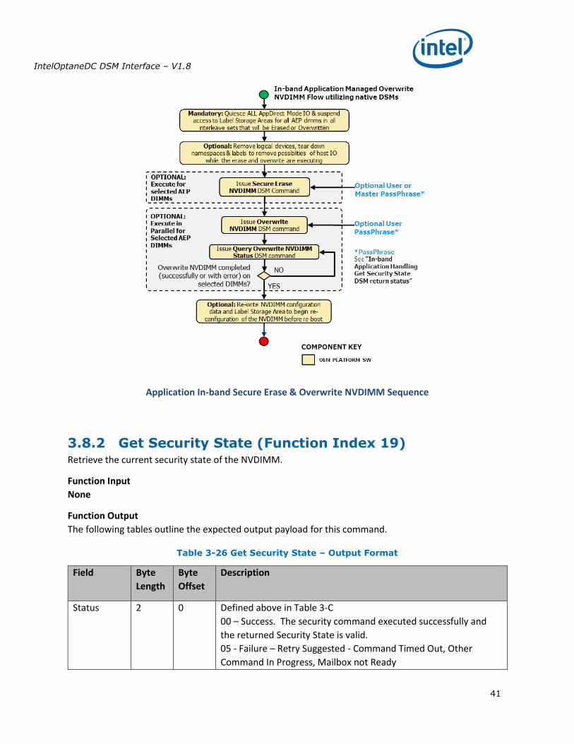
3.8.1 Theory Of Operation The following sequences outline the supported DSM based Secure Erase NVDIMM and Overwrite
NVDIMM execution flow that utilizes an in-band application. Note the following notes regarding the in-
band DSM based security implementation:
The NVDIMM implements a security model similar to the legacy SATA/SCSI ATA security model
utilized with HDDs and SSDs.
To support this, the NVDIMM requires a pass phrase to enable security on the NVDIMM, disable
of previously enabled NVDIMM security, Secure Erase NVDIMM and Overwrite NVDIMM
requests.
Removing the logical devices from access by the running OS while the Secure Erase and
Overwrite NVDIMM operations are executed is recommended to remove any interactions with
host IO while the erase or overwrite are executing.
Speculative reads from the mapped in PMEM will pollute cpu caches with all 1’s data for a
locked NVDIMM. It is imperative that the system either be restarted before first read access, OR
cpu caches are invalidated before the first read access is allowed, after unlocking the NVDIMM.
The DSM commands do NOT invalidate cpu caches.
The NVDIMM allows access to the Label Storage Area and PMEM after the Overwrite NVDIMM
completes and before the system has been restarted with a cold system re-boot. This allows
optional re-configuration of the NVDIMM, including the initial re-write of the Label Storage Area
to occur before the first reboot in the configuration process.
In-Band Managed Overwrite NVDIMM Operation utilizing native DSMs:
o This is an OEM implementation specific function required when overwriting AEP DIMMs
without BIOS intervention or system reboots
o Requires that all IO be quiesced for AppDirect regions before execution
o May require passphrase knowledge to be available to ring3/0 application
Requires no system re-boots until after Overwrite NVDIMM is complete
In-band Applications utilizes the following mechanisms to handle the Secure Erase and
Overwrite NVDIMM implementation:
o DSM V1.7 Spec - Native DSMs are added for the following security commands to match
FIS V1.12:
GetSecurityState
SetPassphrase
DisablePassphrase
UnlockUnit
FreezeLock
SecureEraseNVDIMM
OverwriteNVDIMM
QueryOverwriteNVDIMMStatus
IntelOptaneDC DSM Interface – V1.8
39
o DSM V1.8 Spec - Native DSMs are added for the following security commands to match
FIS V1.13:
SetMasterPassphrase
o Secure Erase NVDIMM DSM broken in to Secure Erase NVDIMM w User Passphrase and
Secure Erase NVDIMM w Master Passphrase DSMs. This allowed preserving backwards
compatibility with the V1.7 DSM spec and released OS support code while adding the
Master Passphrase support. This requires some BIOS translation to complete the
payload mapping.
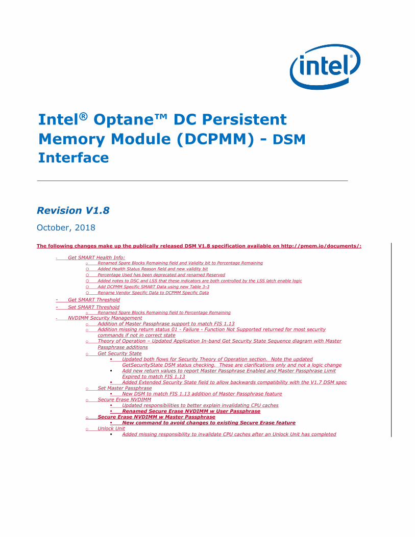
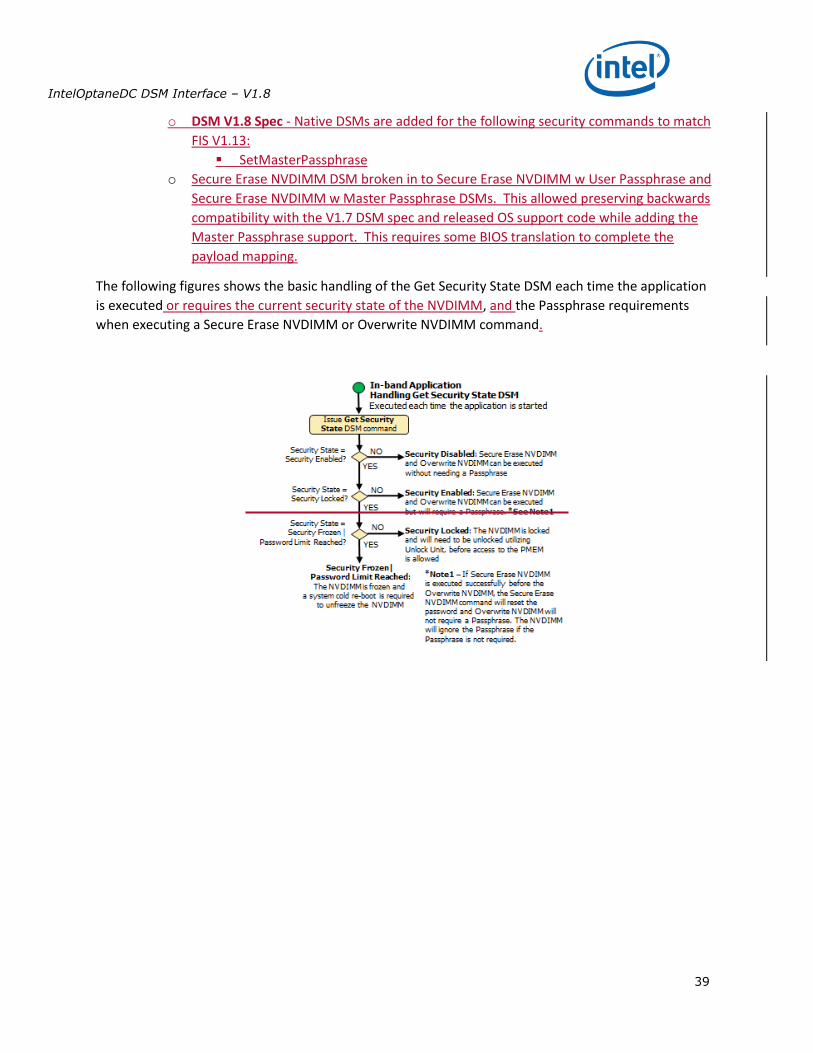
The following figures shows the basic handling of the Get Security State DSM each time the application
is executed or requires the current security state of the NVDIMM, and the Passphrase requirements
when executing a Secure Erase NVDIMM or Overwrite NVDIMM command.
IntelOptaneDC DSM Interface – V1.8
40
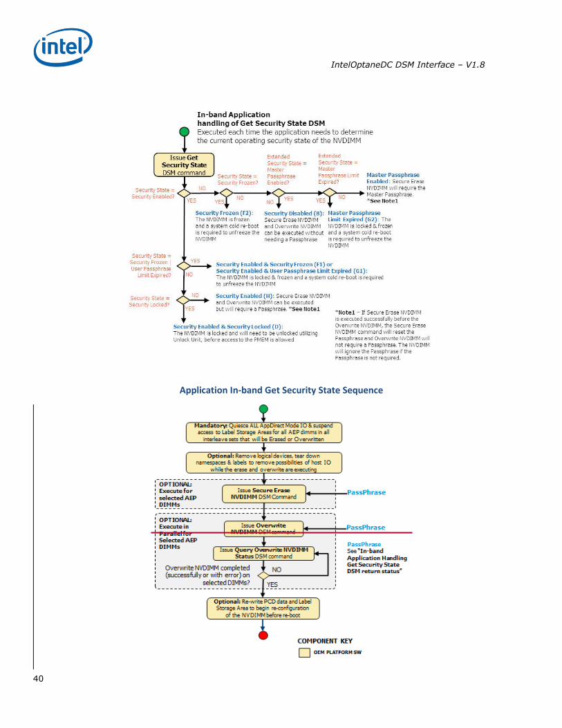
Application In-band Get Security State Sequence
IntelOptaneDC DSM Interface – V1.8
41
Application In-band Secure Erase & Overwrite NVDIMM Sequence
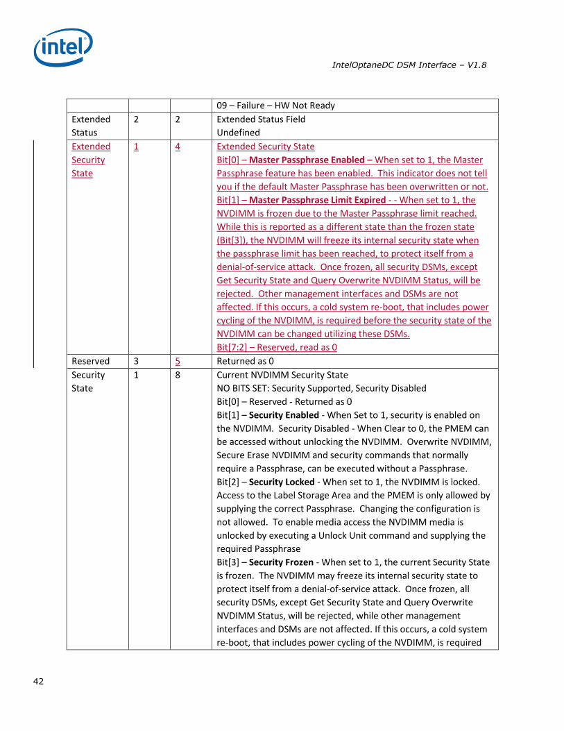
3.8.2 Get Security State (Function Index 19) Retrieve the current security state of the NVDIMM.
Function Input
None
Function Output
The following tables outline the expected output payload for this command.
Table 3-26 Get Security State – Output Format
Field Byte
Length
Byte
Offset
Description
Status 2 0 Defined above in Table 3-C
00 – Success. The security command executed successfully and
the returned Security State is valid.
05 - Failure – Retry Suggested - Command Timed Out, Other
Command In Progress, Mailbox not Ready
IntelOptaneDC DSM Interface – V1.8
42
09 – Failure – HW Not Ready
Extended
Status
2 2 Extended Status Field
Undefined
Extended
Security
State
1 4 Extended Security State
Bit[0] – Master Passphrase Enabled – When set to 1, the Master
Passphrase feature has been enabled. This indicator does not tell
you if the default Master Passphrase has been overwritten or not.
Bit[1] – Master Passphrase Limit Expired - - When set to 1, the
NVDIMM is frozen due to the Master Passphrase limit reached.
While this is reported as a different state than the frozen state
(Bit[3]), the NVDIMM will freeze its internal security state when
the passphrase limit has been reached, to protect itself from a
denial-of-service attack. Once frozen, all security DSMs, except
Get Security State and Query Overwrite NVDIMM Status, will be
rejected. Other management interfaces and DSMs are not
affected. If this occurs, a cold system re-boot, that includes power
cycling of the NVDIMM, is required before the security state of the
NVDIMM can be changed utilizing these DSMs.
Bit[7:2] – Reserved, read as 0
Reserved 3 5 Returned as 0
Security
State
1 8 Current NVDIMM Security State
NO BITS SET: Security Supported, Security Disabled
Bit[0] – Reserved - Returned as 0
Bit[1] – Security Enabled - When Set to 1, security is enabled on
the NVDIMM. Security Disabled - When Clear to 0, the PMEM can
be accessed without unlocking the NVDIMM. Overwrite NVDIMM,
Secure Erase NVDIMM and security commands that normally
require a Passphrase, can be executed without a Passphrase.
Bit[2] – Security Locked - When set to 1, the NVDIMM is locked.
Access to the Label Storage Area and the PMEM is only allowed by
supplying the correct Passphrase. Changing the configuration is
not allowed. To enable media access the NVDIMM media is
unlocked by executing a Unlock Unit command and supplying the
required Passphrase
Bit[3] – Security Frozen - When set to 1, the current Security State
is frozen. The NVDIMM may freeze its internal security state to
protect itself from a denial-of-service attack. Once frozen, all
security DSMs, except Get Security State and Query Overwrite
NVDIMM Status, will be rejected, while other management
interfaces and DSMs are not affected. If this occurs, a cold system
re-boot, that includes power cycling of the NVDIMM, is required
IntelOptaneDC DSM Interface – V1.8
43
before the security state of the NVDIMM can be changed utilizing
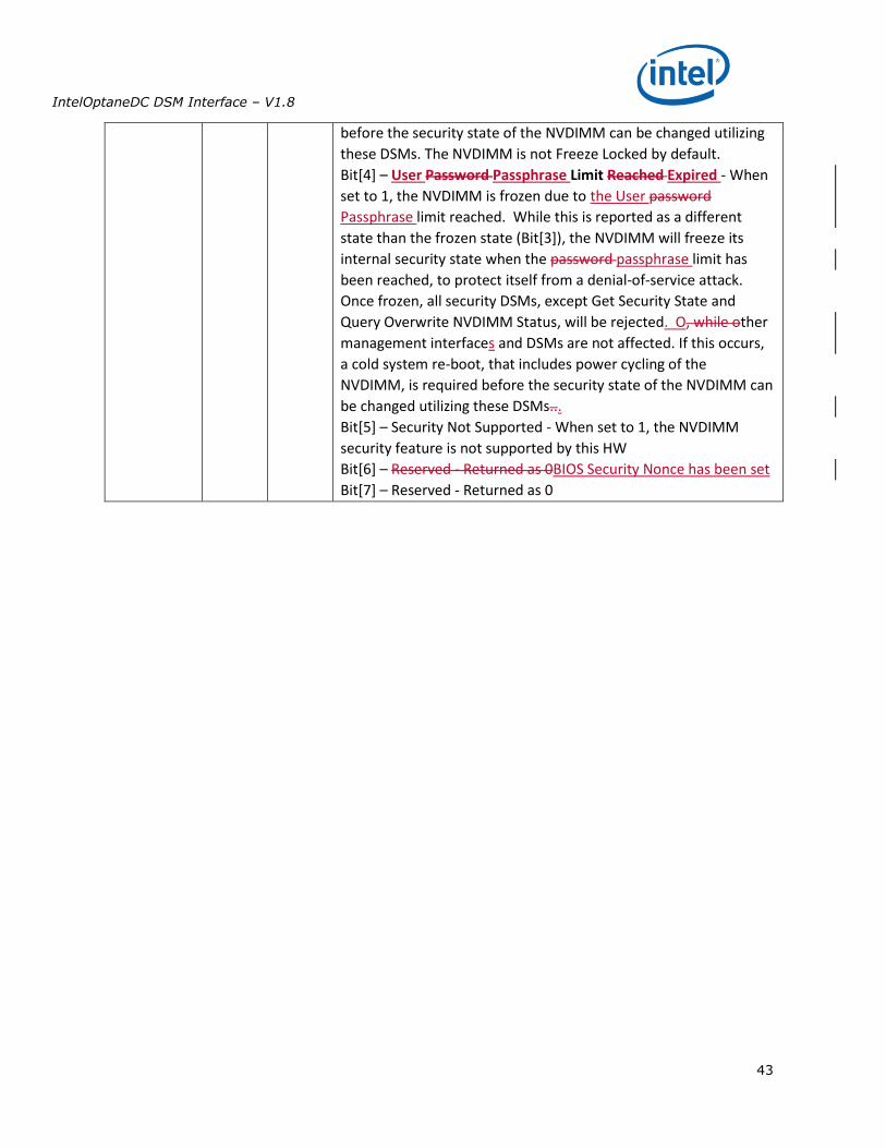
these DSMs. The NVDIMM is not Freeze Locked by default.
Bit[4] – User Password Passphrase Limit Reached Expired - When
set to 1, the NVDIMM is frozen due to the User password
Passphrase limit reached. While this is reported as a different
state than the frozen state (Bit[3]), the NVDIMM will freeze its
internal security state when the password passphrase limit has
been reached, to protect itself from a denial-of-service attack.
Once frozen, all security DSMs, except Get Security State and
Query Overwrite NVDIMM Status, will be rejected. O, while other
management interfaces and DSMs are not affected. If this occurs,
a cold system re-boot, that includes power cycling of the
NVDIMM, is required before the security state of the NVDIMM can
be changed utilizing these DSMs...
Bit[5] – Security Not Supported - When set to 1, the NVDIMM
security feature is not supported by this HW
Bit[6] – Reserved - Returned as 0BIOS Security Nonce has been set
Bit[7] – Reserved - Returned as 0
IntelOptaneDC DSM Interface – V1.8
44
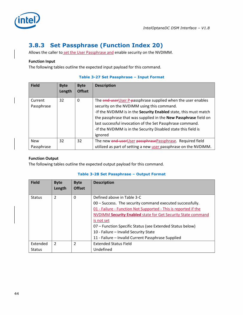
3.8.3 Set Passphrase (Function Index 20) Allows the caller to set the User Passphrase and enable security on the NVDIMM.
Function Input
The following tables outline the expected input payload for this command.
Table 3-27 Set Passphrase – Input Format
Field Byte
Length
Byte
Offset
Description
Current
Passphrase
32 0 The end-userUser P passphrase supplied when the user enables
security on the NVDIMM using this command.
-If the NVDIMM is in the Security Enabled state, this must match
the passphrase that was supplied in the New Passphrase field on
last successful invocation of the Set Passphrase command.
-If the NVDIMM is in the Security Disabled state this field is
ignored
New
Passphrase
32 32 The new end-userUser passphrasePassphrase. Required field
utilized as part of setting a new user passphrase on the NVDIMM.
Function Output
The following tables outline the expected output payload for this command.
Table 3-28 Set Passphrase – Output Format
Field Byte
Length
Byte
Offset
Description
Status 2 0 Defined above in Table 3-C
00 – Success. The security command executed successfully.
01 - Failure - Function Not Supported - This is reported if the
NVDIMM Security Enabled state for Get Security State command
is not set
07 – Function Specific Status (see Extended Status below)
10 - Failure – Invalid Security State
11 - Failure – Invalid Current Passphrase Supplied
Extended
Status
2 2 Extended Status Field
Undefined
IntelOptaneDC DSM Interface – V1.8
45
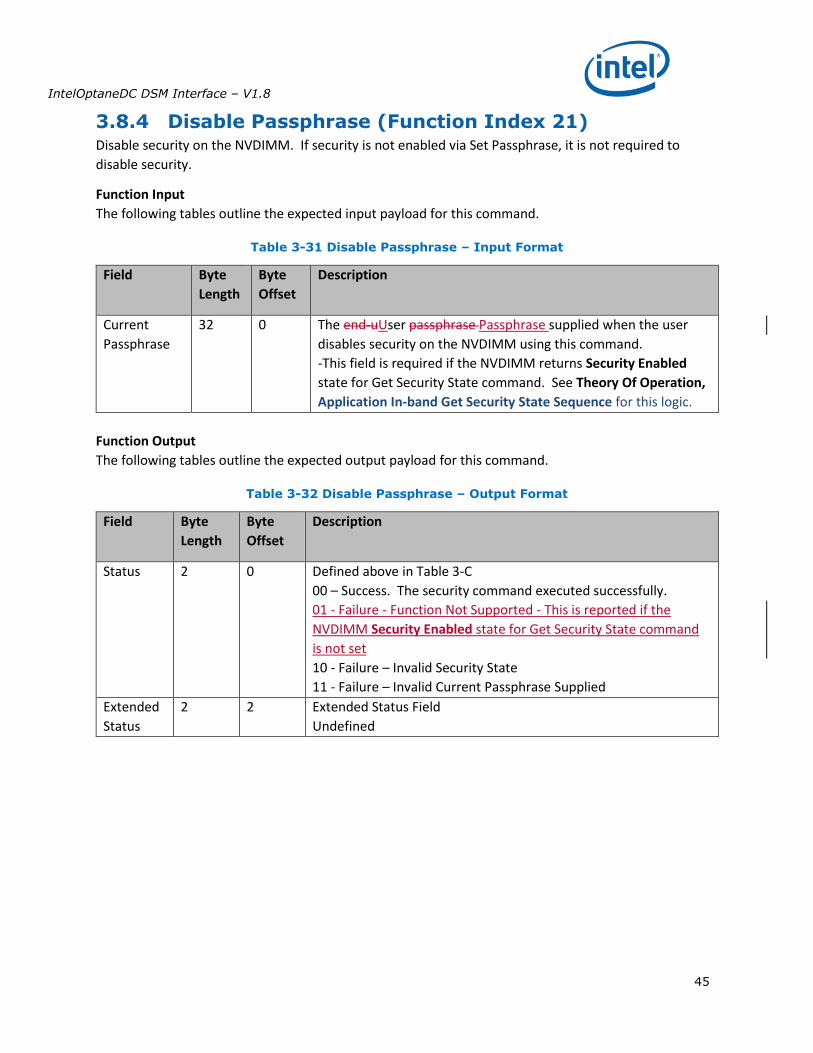
3.8.4 Disable Passphrase (Function Index 21) Disable security on the NVDIMM. If security is not enabled via Set Passphrase, it is not required to
disable security.
Function Input
The following tables outline the expected input payload for this command.
Table 3-31 Disable Passphrase – Input Format
Field Byte
Length
Byte
Offset
Description
Current
Passphrase
32 0 The end-uUser passphrase Passphrase supplied when the user
disables security on the NVDIMM using this command.
-This field is required if the NVDIMM returns Security Enabled
state for Get Security State command. See Theory Of Operation,
Application In-band Get Security State Sequence for this logic.
Function Output
The following tables outline the expected output payload for this command.
Table 3-32 Disable Passphrase – Output Format
Field Byte
Length
Byte
Offset
Description
Status 2 0 Defined above in Table 3-C
00 – Success. The security command executed successfully.
01 - Failure - Function Not Supported - This is reported if the
NVDIMM Security Enabled state for Get Security State command
is not set
10 - Failure – Invalid Security State
11 - Failure – Invalid Current Passphrase Supplied
Extended
Status
2 2 Extended Status Field
Undefined
IntelOptaneDC DSM Interface – V1.8
46
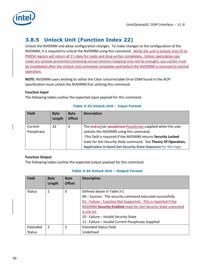
3.8.5 Unlock Unit (Function Index 22) Unlock the NVDIMM and allow configuration changes. To make changes to the configuration of the
NVDIMM, it is required to unlock the NVDIMM using this command. While the unit is locked, host IO to
PMEM regions will return all 1’s data for reads and drop writes completely. Unless speculative cpu
reads are actively prevented (removing virtual memory mapping may not be enough), cpu caches must
be invalidated after the Unlock Unit command completes and before the NVDIMM is returned to normal
operation.
NOTE: NVDIMM users wishing to utilize the Clear Uncorrectable Error DSM found in the ACPI
specification must unlock the NVDIMM first utilizing this command.
Function Input
The following tables outline the expected input payload for this command.
Table 3-33 Unlock Unit – Input Format
Field Byte
Length
Byte
Offset
Description
Current
Passphrase
32 0 The end-uUser passphrase Passphrase supplied when the user
unlocks the NVDIMM using this command.
-This field is required if the NVDIMM returns Security Locked
state for Get Security State command. See Theory Of Operation,
Application In-band Get Security State Sequence for this logic.
Function Output
The following tables outline the expected output payload for this command.
Table 3-34 Unlock Unit – Output Format
Field Byte
Length
Byte
Offset
Description
Status 2 0 Defined above in Table 3-C
00 – Success. The security command executed successfully.
01 - Failure - Function Not Supported - This is reported if the
NVDIMM Security Enabled state for Get Security State command
is not set
10 - Failure – Invalid Security State
11 - Failure – Invalid Current Passphrase Supplied
Extended
Status
2 2 Extended Status Field
Undefined
IntelOptaneDC DSM Interface – V1.8
47
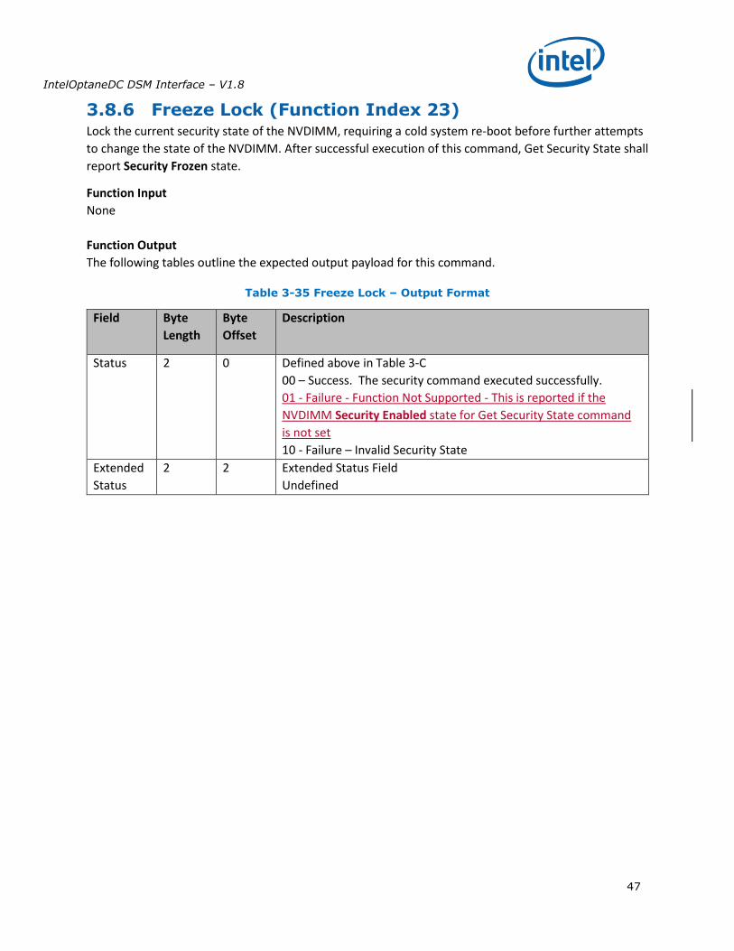
3.8.6 Freeze Lock (Function Index 23) Lock the current security state of the NVDIMM, requiring a cold system re-boot before further attempts
to change the state of the NVDIMM. After successful execution of this command, Get Security State shall
report Security Frozen state.
Function Input
None
Function Output
The following tables outline the expected output payload for this command.
Table 3-35 Freeze Lock – Output Format
Field Byte
Length
Byte
Offset
Description
Status 2 0 Defined above in Table 3-C
00 – Success. The security command executed successfully.
01 - Failure - Function Not Supported - This is reported if the
NVDIMM Security Enabled state for Get Security State command
is not set
10 - Failure – Invalid Security State
Extended
Status
2 2 Extended Status Field
Undefined
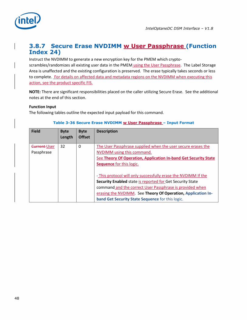
IntelOptaneDC DSM Interface – V1.8
48
3.8.7 Secure Erase NVDIMM w User Passphrase (Function Index 24) Instruct the NVDIMM to generate a new encryption key for the PMEM which crypto-
scrambles/randomizes all existing user data in the PMEM using the User Passphrase. The Label Storage
Area is unaffected and the existing configuration is preserved. The erase typically takes seconds or less
to complete. For details on affected data and metadata regions on the NVDIMM when executing this
action, see the product specific FIS.
NOTE: There are significant responsibilities placed on the caller utilizing Secure Erase. See the additional
notes at the end of this section.
Function Input
The following tables outline the expected input payload for this command.
Table 3-36 Secure Erase NVDIMM w User Passphrase – Input Format
Field Byte
Length
Byte
Offset
Description
Current User
Passphrase
32 0 The User Passphrase supplied when the user secure erases the
NVDIMM using this command.
See Theory Of Operation, Application In-band Get Security State
Sequence for this logic.
- This protocol will only successfully erase the NVDIMM If the
Security Enabled state is reported for Get Security State
command and the correct User Passphrase is provided when
erasing the NVDIMM. See Theory Of Operation, Application In-
band Get Security State Sequence for this logic.
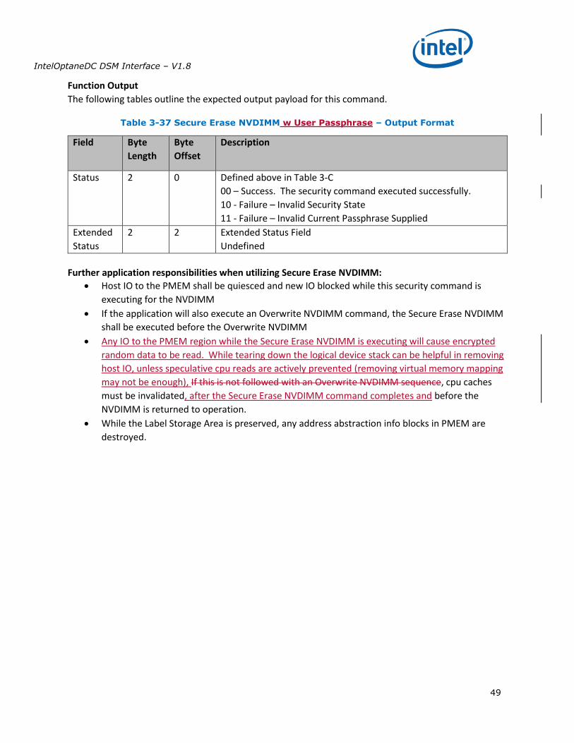
IntelOptaneDC DSM Interface – V1.8
49
Function Output
The following tables outline the expected output payload for this command.
Table 3-37 Secure Erase NVDIMM w User Passphrase – Output Format
Field Byte
Length
Byte
Offset
Description
Status 2 0 Defined above in Table 3-C
00 – Success. The security command executed successfully.
10 - Failure – Invalid Security State
11 - Failure – Invalid Current Passphrase Supplied
Extended
Status
2 2 Extended Status Field
Undefined
Further application responsibilities when utilizing Secure Erase NVDIMM:
Host IO to the PMEM shall be quiesced and new IO blocked while this security command is
executing for the NVDIMM
If the application will also execute an Overwrite NVDIMM command, the Secure Erase NVDIMM
shall be executed before the Overwrite NVDIMM
Any IO to the PMEM region while the Secure Erase NVDIMM is executing will cause encrypted
random data to be read. While tearing down the logical device stack can be helpful in removing
host IO, unless speculative cpu reads are actively prevented (removing virtual memory mapping
may not be enough), If this is not followed with an Overwrite NVDIMM sequence, cpu caches
must be invalidated, after the Secure Erase NVDIMM command completes and before the
NVDIMM is returned to operation.
While the Label Storage Area is preserved, any address abstraction info blocks in PMEM are
destroyed.
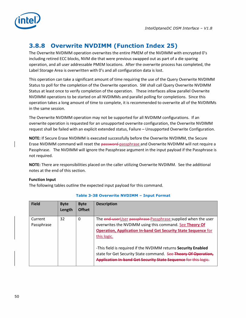
IntelOptaneDC DSM Interface – V1.8
50
3.8.8 Overwrite NVDIMM (Function Index 25) The Overwrite NVDIMM operation overwrites the entire PMEM of the NVDIMM with encrypted 0’s
including retired ECC blocks, NVM die that were previous swapped out as part of a die sparing
operation, and all user addressable PMEM locations. After the overwrite process has completed, the
Label Storage Area is overwritten with 0’s and all configuration data is lost.
This operation can take a significant amount of time requiring the use of the Query Overwrite NVDIMM
Status to poll for the completion of the Overwrite operation. SW shall call Query Overwrite NVDIMM
Status at least once to verify completion of the operation. These interfaces allow parallel Overwrite
NVDIMM operations to be started on all NVDIMMs and parallel polling for completions. Since this
operation takes a long amount of time to complete, it is recommended to overwrite all of the NVDIMMs
in the same session.
The Overwrite NVDIMM operation may not be supported for all NVDIMM configurations. If an
overwrite operation is requested for an unsupported overwrite configuration, the Overwrite NVDIMM
request shall be failed with an explicit extended status, Failure – Unsupported Overwrite Configuration.
NOTE: If Secure Erase NVDIMM is executed successfully before the Overwrite NVDIMM, the Secure
Erase NVDIMM command will reset the password passphrase and Overwrite NVDIMM will not require a
Passphrase. The NVDIMM will ignore the Passphrase argument in the input payload if the Passphrase is
not required.
NOTE: There are responsibilities placed on the caller utilizing Overwrite NVDIMM. See the additional
notes at the end of this section.
Function Input
The following tables outline the expected input payload for this command.
Table 3-38 Overwrite NVDIMM – Input Format
Field Byte
Length
Byte
Offset
Description
Current
Passphrase
32 0 The end-userUser passphrase Passphrase supplied when the user
overwrites the NVDIMM using this command. See Theory Of
Operation, Application In-band Get Security State Sequence for
this logic.
-This field is required if the NVDIMM returns Security Enabled
state for Get Security State command. See Theory Of Operation,
Application In-band Get Security State Sequence for this logic.
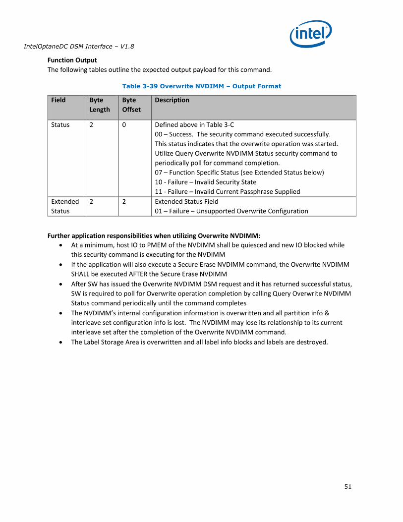
IntelOptaneDC DSM Interface – V1.8
51
Function Output
The following tables outline the expected output payload for this command.
Table 3-39 Overwrite NVDIMM – Output Format
Field Byte
Length
Byte
Offset
Description
Status 2 0 Defined above in Table 3-C
00 – Success. The security command executed successfully.
This status indicates that the overwrite operation was started.
Utilize Query Overwrite NVDIMM Status security command to
periodically poll for command completion.
07 – Function Specific Status (see Extended Status below)
10 - Failure – Invalid Security State
11 - Failure – Invalid Current Passphrase Supplied
Extended
Status
2 2 Extended Status Field
01 – Failure – Unsupported Overwrite Configuration
Further application responsibilities when utilizing Overwrite NVDIMM:
At a minimum, host IO to PMEM of the NVDIMM shall be quiesced and new IO blocked while
this security command is executing for the NVDIMM
If the application will also execute a Secure Erase NVDIMM command, the Overwrite NVDIMM
SHALL be executed AFTER the Secure Erase NVDIMM
After SW has issued the Overwrite NVDIMM DSM request and it has returned successful status,
SW is required to poll for Overwrite operation completion by calling Query Overwrite NVDIMM
Status command periodically until the command completes
The NVDIMM’s internal configuration information is overwritten and all partition info &
interleave set configuration info is lost. The NVDIMM may lose its relationship to its current
interleave set after the completion of the Overwrite NVDIMM command.
The Label Storage Area is overwritten and all label info blocks and labels are destroyed.
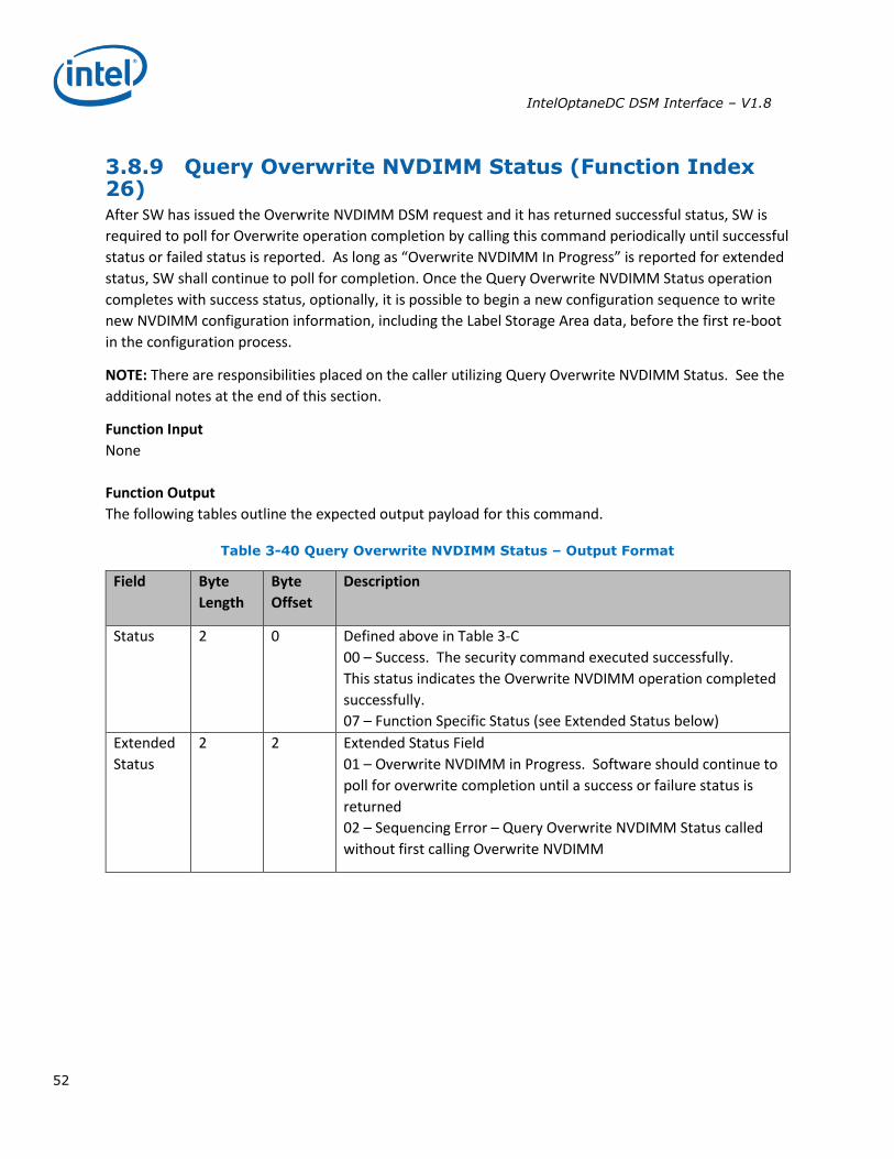
IntelOptaneDC DSM Interface – V1.8
52
3.8.9 Query Overwrite NVDIMM Status (Function Index 26) After SW has issued the Overwrite NVDIMM DSM request and it has returned successful status, SW is
required to poll for Overwrite operation completion by calling this command periodically until successful
status or failed status is reported. As long as “Overwrite NVDIMM In Progress” is reported for extended
status, SW shall continue to poll for completion. Once the Query Overwrite NVDIMM Status operation
completes with success status, optionally, it is possible to begin a new configuration sequence to write
new NVDIMM configuration information, including the Label Storage Area data, before the first re-boot
in the configuration process.
NOTE: There are responsibilities placed on the caller utilizing Query Overwrite NVDIMM Status. See the
additional notes at the end of this section.
Function Input
None
Function Output
The following tables outline the expected output payload for this command.
Table 3-40 Query Overwrite NVDIMM Status – Output Format
Field Byte
Length
Byte
Offset
Description
Status 2 0 Defined above in Table 3-C
00 – Success. The security command executed successfully.
This status indicates the Overwrite NVDIMM operation completed
successfully.
07 – Function Specific Status (see Extended Status below)
Extended
Status
2 2 Extended Status Field
01 – Overwrite NVDIMM in Progress. Software should continue to
poll for overwrite completion until a success or failure status is
returned
02 – Sequencing Error – Query Overwrite NVDIMM Status called
without first calling Overwrite NVDIMM
IntelOptaneDC DSM Interface – V1.8
53
Further application responsibilities when utilizing Query Overwrite NVDIMM Status:
Host IO to the PMEM of the NVDIMM shall be quiesced and new IO blocked while this security
command continues to report “Overwrite NVDIMM In Progress”.
If the Overwrite NVDIMM fails to complete with success the state of the NVDIMM is
indeterminate and it is recommended that the Overwrite be executed again.
The Overwrite NVDIMM operation takes a significant amount of time to complete: 15min -
128GB, 30min - 256GB, 60min – 512GB, etc. There for, it is recommended that SW poll for
completion with an interval of 10-60 seconds.. These values can also be used as a guide as to
when SW may want to give up on polling for successful completion. Implementations may wish
to issue the first query with a small timeout to make sure the Overwrite NVDIMM is still
executing before moving to a longer polling frequencies for the rest of the query calls.
Note: It is possible to issue other DSMs while the Overwrite is executing so SW can monitor the DIMM health and temperature (for example) while the Overwrite DIMM executes. Other operations (ARS, FW Update) are not allowed and those DSMs will be rejected.
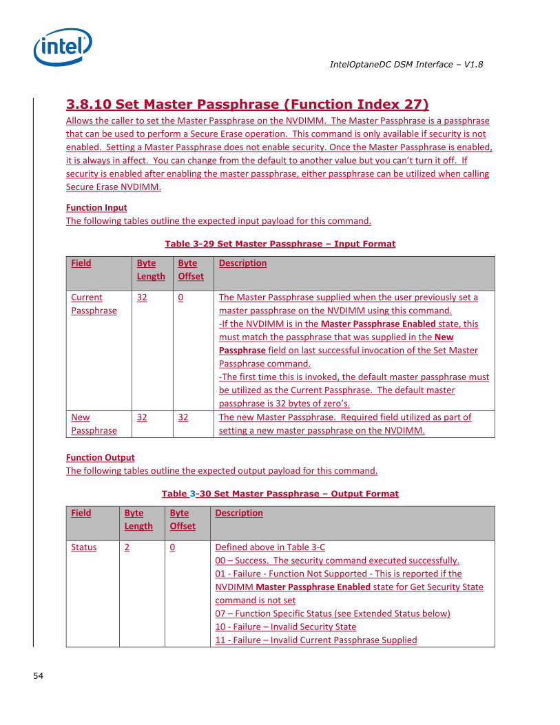
IntelOptaneDC DSM Interface – V1.8
54
3.8.10 Set Master Passphrase (Function Index 27) Allows the caller to set the Master Passphrase on the NVDIMM. The Master Passphrase is a passphrase
that can be used to perform a Secure Erase operation. This command is only available if security is not
enabled. Setting a Master Passphrase does not enable security. Once the Master Passphrase is enabled,
it is always in affect. You can change from the default to another value but you can’t turn it off. If
security is enabled after enabling the master passphrase, either passphrase can be utilized when calling
Secure Erase NVDIMM.
Function Input
The following tables outline the expected input payload for this command.
Table 3-29 Set Master Passphrase – Input Format
Field Byte
Length
Byte
Offset
Description
Current
Passphrase
32 0 The Master Passphrase supplied when the user previously set a
master passphrase on the NVDIMM using this command.
-If the NVDIMM is in the Master Passphrase Enabled state, this
must match the passphrase that was supplied in the New
Passphrase field on last successful invocation of the Set Master
Passphrase command.
-The first time this is invoked, the default master passphrase must
be utilized as the Current Passphrase. The default master
passphrase is 32 bytes of zero’s.
New
Passphrase
32 32 The new Master Passphrase. Required field utilized as part of
setting a new master passphrase on the NVDIMM.
Function Output
The following tables outline the expected output payload for this command.
Table 3-30 Set Master Passphrase – Output Format
Field Byte
Length
Byte
Offset
Description
Status 2 0 Defined above in Table 3-C
00 – Success. The security command executed successfully.
01 - Failure - Function Not Supported - This is reported if the
NVDIMM Master Passphrase Enabled state for Get Security State
command is not set
07 – Function Specific Status (see Extended Status below)
10 - Failure – Invalid Security State
11 - Failure – Invalid Current Passphrase Supplied

IntelOptaneDC DSM Interface – V1.8
55
Extended
Status
2 2 Extended Status Field
Undefined

IntelOptaneDC DSM Interface – V1.8
56
3.8.11 Secure Erase NVDIMM w Master Passphrase (Function Index 28) Instruct the NVDIMM to generate a new encryption key for the PMEM which crypto-
scrambles/randomizes all existing user data in the PMEM, using the Master Passphrase. The Label
Storage Area is unaffected and the existing configuration is preserved. The erase typically takes seconds
or less to complete. For details on affected data and metadata regions on the NVDIMM when executing
this action, see the product specific FIS.
NOTE: There are significant responsibilities placed on the caller utilizing Secure Erase. See the additional
notes at the end of this section.
Function Input
The following tables outline the expected input payload for this command.
Table 3-36 Secure Erase NVDIMM w Master Passphrase – Input Format
Field Byte
Length
Byte
Offset
Description
Master
Passphrase
32 0 The Master Passphrase supplied when the user secure erases the
NVDIMM using this command.
See Theory Of Operation, Application In-band Get Security State
Sequence for this logic.
-This protocol will only successfully erase the NVDIMM If the
Master Passphrase Enabled state is reported for Get Security
State command and the correct Master Passphrase is provided
when erasing the NVDIMM.
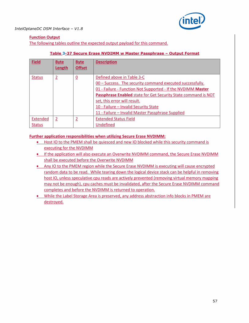
IntelOptaneDC DSM Interface – V1.8
57
Function Output
The following tables outline the expected output payload for this command.
Table 3-37 Secure Erase NVDIMM w Master Passphrase – Output Format
Field Byte
Length
Byte
Offset
Description
Status 2 0 Defined above in Table 3-C
00 – Success. The security command executed successfully.
01 - Failure - Function Not Supported - If the NVDIMM Master
Passphrase Enabled state for Get Security State command is NOT
set, this error will result.
10 - Failure – Invalid Security State
11 - Failure – Invalid Master Passphrase Supplied
Extended
Status
2 2 Extended Status Field
Undefined
Further application responsibilities when utilizing Secure Erase NVDIMM:
Host IO to the PMEM shall be quiesced and new IO blocked while this security command is
executing for the NVDIMM
If the application will also execute an Overwrite NVDIMM command, the Secure Erase NVDIMM
shall be executed before the Overwrite NVDIMM
Any IO to the PMEM region while the Secure Erase NVDIMM is executing will cause encrypted
random data to be read. While tearing down the logical device stack can be helpful in removing
host IO, unless speculative cpu reads are actively prevented (removing virtual memory mapping
may not be enough), cpu caches must be invalidated, after the Secure Erase NVDIMM command
completes and before the NVDIMM is returned to operation.
While the Label Storage Area is preserved, any address abstraction info blocks in PMEM are
destroyed.
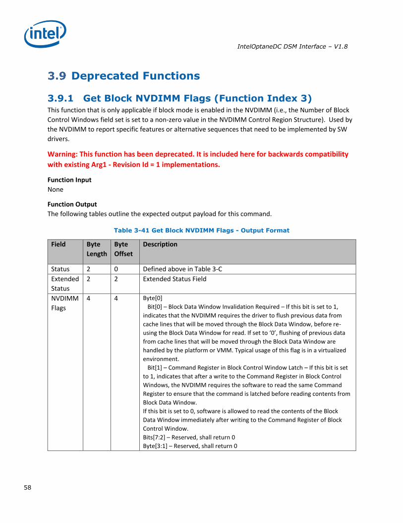
IntelOptaneDC DSM Interface – V1.8
58
Deprecated Functions
3.9.1 Get Block NVDIMM Flags (Function Index 3) This function that is only applicable if block mode is enabled in the NVDIMM (i.e., the Number of Block
Control Windows field set is set to a non-zero value in the NVDIMM Control Region Structure). Used by
the NVDIMM to report specific features or alternative sequences that need to be implemented by SW
drivers.
Warning: This function has been deprecated. It is included here for backwards compatibility
with existing Arg1 - Revision Id = 1 implementations.
Function Input
None
Function Output
The following tables outline the expected output payload for this command.
Table 3-41 Get Block NVDIMM Flags - Output Format
Field Byte
Length
Byte
Offset
Description
Status 2 0 Defined above in Table 3-C
Extended
Status
2 2 Extended Status Field
NVDIMM
Flags
4 4 Byte[0]
Bit[0] – Block Data Window Invalidation Required – If this bit is set to 1,
indicates that the NVDIMM requires the driver to flush previous data from
cache lines that will be moved through the Block Data Window, before re-
using the Block Data Window for read. If set to ‘0’, flushing of previous data
from cache lines that will be moved through the Block Data Window are
handled by the platform or VMM. Typical usage of this flag is in a virtualized
environment.
Bit[1] – Command Register in Block Control Window Latch – If this bit is set
to 1, indicates that after a write to the Command Register in Block Control
Windows, the NVDIMM requires the software to read the same Command
Register to ensure that the command is latched before reading contents from
Block Data Window.
If this bit is set to 0, software is allowed to read the contents of the Block
Data Window immediately after writing to the Command Register of Block
Control Window.
Bits[7:2] – Reserved, shall return 0
Byte[3:1] – Reserved, shall return 0
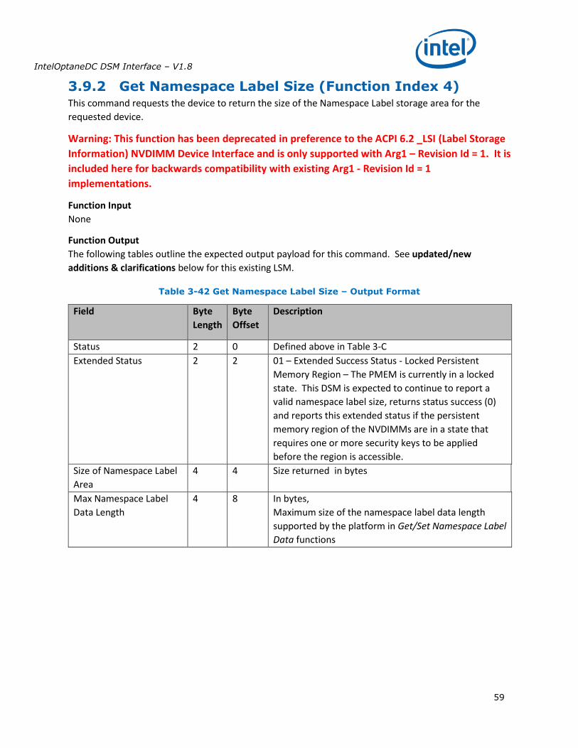
IntelOptaneDC DSM Interface – V1.8
59
3.9.2 Get Namespace Label Size (Function Index 4) This command requests the device to return the size of the Namespace Label storage area for the
requested device.
Warning: This function has been deprecated in preference to the ACPI 6.2 _LSI (Label Storage
Information) NVDIMM Device Interface and is only supported with Arg1 – Revision Id = 1. It is
included here for backwards compatibility with existing Arg1 - Revision Id = 1
implementations.
Function Input
None
Function Output
The following tables outline the expected output payload for this command. See updated/new
additions & clarifications below for this existing LSM.
Table 3-42 Get Namespace Label Size – Output Format
Field Byte
Length
Byte
Offset
Description
Status 2 0 Defined above in Table 3-C
Extended Status 2 2 01 – Extended Success Status - Locked Persistent
Memory Region – The PMEM is currently in a locked
state. This DSM is expected to continue to report a
valid namespace label size, returns status success (0)
and reports this extended status if the persistent
memory region of the NVDIMMs are in a state that
requires one or more security keys to be applied
before the region is accessible.
Size of Namespace Label
Area
4 4 Size returned in bytes
Max Namespace Label
Data Length
4 8 In bytes,
Maximum size of the namespace label data length
supported by the platform in Get/Set Namespace Label
Data functions
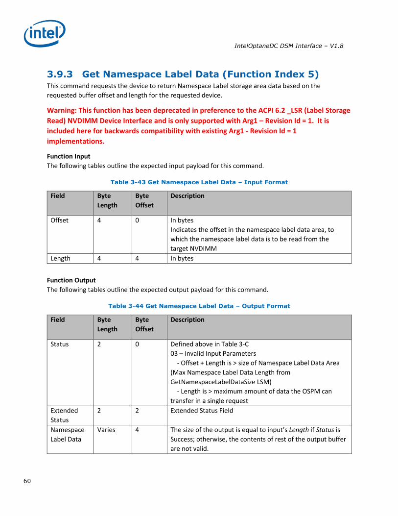
IntelOptaneDC DSM Interface – V1.8
60
3.9.3 Get Namespace Label Data (Function Index 5) This command requests the device to return Namespace Label storage area data based on the
requested buffer offset and length for the requested device.
Warning: This function has been deprecated in preference to the ACPI 6.2 _LSR (Label Storage
Read) NVDIMM Device Interface and is only supported with Arg1 – Revision Id = 1. It is
included here for backwards compatibility with existing Arg1 - Revision Id = 1
implementations.
Function Input
The following tables outline the expected input payload for this command.
Table 3-43 Get Namespace Label Data – Input Format
Field Byte
Length
Byte
Offset
Description
Offset 4 0 In bytes
Indicates the offset in the namespace label data area, to
which the namespace label data is to be read from the
target NVDIMM
Length 4 4 In bytes
Function Output
The following tables outline the expected output payload for this command.
Table 3-44 Get Namespace Label Data – Output Format
Field Byte
Length
Byte
Offset
Description
Status 2 0 Defined above in Table 3-C
03 – Invalid Input Parameters
- Offset + Length is > size of Namespace Label Data Area
(Max Namespace Label Data Length from
GetNamespaceLabelDataSize LSM)
- Length is > maximum amount of data the OSPM can
transfer in a single request
Extended
Status
2 2 Extended Status Field
Namespace
Label Data
Varies 4 The size of the output is equal to input’s Length if Status is
Success; otherwise, the contents of rest of the output buffer
are not valid.
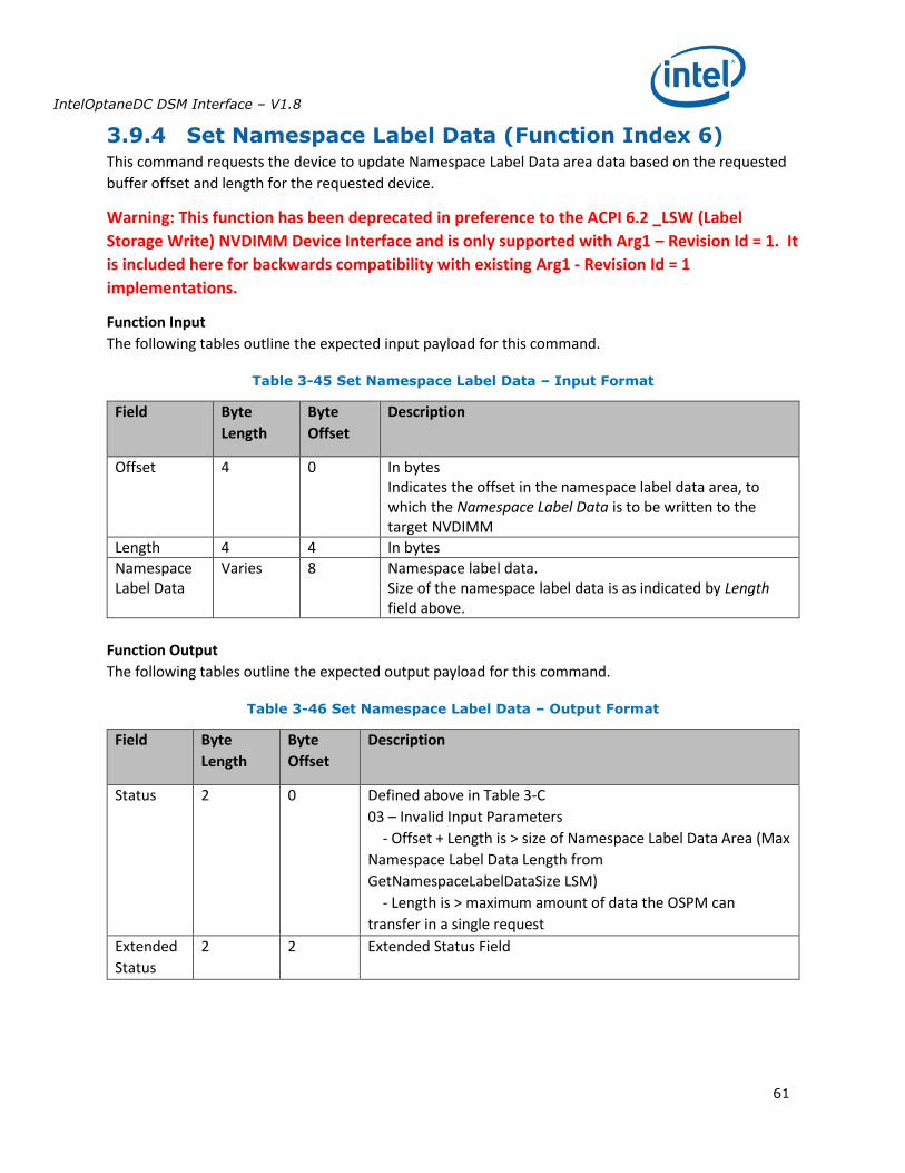
IntelOptaneDC DSM Interface – V1.8
61
3.9.4 Set Namespace Label Data (Function Index 6) This command requests the device to update Namespace Label Data area data based on the requested
buffer offset and length for the requested device.
Warning: This function has been deprecated in preference to the ACPI 6.2 _LSW (Label
Storage Write) NVDIMM Device Interface and is only supported with Arg1 – Revision Id = 1. It
is included here for backwards compatibility with existing Arg1 - Revision Id = 1
implementations.
Function Input
The following tables outline the expected input payload for this command.
Table 3-45 Set Namespace Label Data – Input Format
Field Byte
Length
Byte
Offset
Description
Offset 4 0 In bytes Indicates the offset in the namespace label data area, to which the Namespace Label Data is to be written to the target NVDIMM
Length 4 4 In bytes
Namespace Label Data
Varies 8 Namespace label data. Size of the namespace label data is as indicated by Length field above.
Function Output
The following tables outline the expected output payload for this command.
Table 3-46 Set Namespace Label Data – Output Format
Field Byte
Length
Byte
Offset
Description
Status 2 0 Defined above in Table 3-C
03 – Invalid Input Parameters
- Offset + Length is > size of Namespace Label Data Area (Max
Namespace Label Data Length from
GetNamespaceLabelDataSize LSM)
- Length is > maximum amount of data the OSPM can
transfer in a single request
Extended
Status
2 2 Extended Status Field