Embed Size (px)
Citation preview

Application of OBD equip-
ment for inspection of heavy
trucks

Side 2 TEKNOLOGISK INSTITUT
Application of OBD equipment for inspec-
tion of heavy trucks
<Teaser tekst>
Færdselsstyrelsen
Sorsigvej 35
6760 Ribe
Made by
Teknologisk Institut
Kongsvang Allé 29
8000 Aarhus C
Transport og Elektriske Systemer
In cooperation with
2M-Teknik
5. April 2021
Author: Kim Winther

Side 3 TEKNOLOGISK INSTITUT
Contents
1. Danish resume (dansk resume) ........................................................................................................................................ 5
2. Introduction .............................................................................................................................................................................. 5
2.1. About On-Board Diagnostics (OBD) .................................................................................................................... 6
2.2. History .............................................................................................................................................................................. 6
2.3. Method used in USA................................................................................................................................................... 7
2.4. Approach used in this report .................................................................................................................................. 7
3. OBD-systems in relation to emissions reduction equipment ............................................................................... 9
3.1. Requirements ................................................................................................................................................................ 9
3.2. Functions ...................................................................................................................................................................... 10
3.2.1. The Malfunction Indicator Lamp (MIL) ................................................................................................... 10
3.2.2. SCR warning system ...................................................................................................................................... 11
3.2.3. PID’s ..................................................................................................................................................................... 11
3.2.4. Readiness monitors........................................................................................................................................ 12
3.2.5. Diagnostic Trouble Codes ........................................................................................................................... 13
3.2.6. Modes ................................................................................................................................................................. 14
3.2.7. IUPR monitors .................................................................................................................................................. 15
4. Inspection setup .................................................................................................................................................................. 15
4.1. The vehicle (test object) ......................................................................................................................................... 16
4.2. The OBD tool (Scan tool, diagnostics tool) .................................................................................................... 16
4.3. The operator (inspector) ........................................................................................................................................ 17
5. Step-by-step inspection procedure ............................................................................................................................. 17
5.1. Step 1 Turn ignition key on/off ........................................................................................................................... 19
5.2. Step 2 Connect Scan tool (OBD level) .............................................................................................................. 19
5.3. Step 3 Move to diagnostics (Expert level) ....................................................................................................... 20
5.4. Step 4 Run calibration/self-test (requires Super PIN) ................................................................................ 21
6. Demonstration of the robustness of the method .................................................................................................. 23
6.1. Test reports ................................................................................................................................................................. 23
6.1.1. Scania S510 brand new ................................................................................................................................ 24
6.1.2. Volvo FH460 in standard trim .................................................................................................................... 25
6.1.3. Volvo FH460 with bad wiring ..................................................................................................................... 26
6.1.4. Scania R520 in standard trim ..................................................................................................................... 27
6.1.5. Scania R520 with software manipulation .............................................................................................. 28
6.1.6. Volvo FH500 in standard trim .................................................................................................................... 29

Side 4 TEKNOLOGISK INSTITUT
6.1.7. Volvo FH500 with bad wiring ..................................................................................................................... 30
6.1.8. Volvo FE280 in standard trim ..................................................................................................................... 31
6.1.9. DAF XE 440 in standard trim ...................................................................................................................... 32
6.1.10. DAF XE 440 with software manipulation ............................................................................................... 33
6.1.11. Iveco Eurocargo 160-280 with software manipulation .................................................................... 34
6.1.12. Mercedes Actros IV 1845 in standard trim ........................................................................................... 35
6.1.13. Mercedes Arcos 2651 in standard trim .................................................................................................. 36
6.1.14. Scania R360 in standard trim ..................................................................................................................... 37
6.1.15. Mercedes Actros 3 2548 in standard trim ............................................................................................. 38
6.1.16. Mercedes Actros IV in standard trim ...................................................................................................... 39
6.1.17. Actros 1845 with possible faults ............................................................................................................... 40
6.1.18. Iveco S-Way 570 brand new....................................................................................................................... 41
6.1.19. Scania G410 in standard trim ..................................................................................................................... 42
6.1.20. Scania G410 with software manipulation .............................................................................................. 43
6.1.21. Scania G410 with emulator ON ................................................................................................................. 44
6.1.22. Scania G410 with emulator OFF ................................................................................................................ 45
6.2. Application at Periodical Technical Inspection (PTI). .................................................................................. 45
7. Conclusion ............................................................................................................................................................................. 46
8. Nomenclature ....................................................................................................................................................................... 47
9. Literature list ......................................................................................................................................................................... 47

Side 5 TEKNOLOGISK INSTITUT
1. Danish resume (dansk resume)
Denne rapport er udført for Færdselsstyrelsen som led i anden fase af regeringens indsats mod snyd med
lastbilers NOX-begrænsende udstyr. Om første fase se kildehenvisning [1].
Rapporten beskriver anvendelsen af OBD (On-Board-Diagnostics) som en metode til at afklare, om det
emissionsbegrænsende udstyr på en lastbil er virksomt eller ej.
Udviklingen af metoden baseres dels på en overordnet gennemgang af OBD-systemets funktionalitet og
dels på test af 15 forskellige lastbiler med og uden fejl I det emissionsbegrænsende udstyr. Nogle af
lastbilerne er bevidst blevet forsynet med snydesoftware eller fysiske fejl, for at undersøge, hvorledes
dette kan afsløres.
Baseret på disse erfaringer udvikles en trin-for-trin metode, som kombinerer OBD-systemets funktionali-
tet med en avanceret diagnosetester samt en række tjekpunkter, som tilsammen indikerer om en lastbil
har et funktionelt emissionsbegrænsende system.
Resultatet viser, at manipulerede eller defekte emissionssystemer med stor sikkerhed kan afsløres på
denne måde. Der kan dog også optræde en række tilstande, som kan understøtte en mistanke, men som
ikke i sig selv er bevis for, at systemet er uvirksomt. Derfor er operatørens tolkning af dataene også en
central del af metoden.
2. Introduction
This report investigates the possible use of On-Board Diagnostics (OBD) in heavy truck vehicle inspection
to detect faulty emission systems and counteract illegal modifications done to the vehicle. A study of the
OBD related regulations shows that current regulations do not offer such an inspection method. A suitable
method is therefore developed as part of the project and included in this report. The robustness of the
method is demonstrated on both fault-free, faulty, and illegally modified heavy trucks.
A PC with a professional OBD inspection tool is used to confirm that the vehicle has a working emission
system and to assess if the software on the vehicle might have been tampered with. The system includes
a Scan tool, a diagnostics tool, and a vehicle self-test mode for advanced users. These tools are discussed
in detail within the report, alongside the important role of the operator.
Disclaimer:
This report has been produced by Danish Technological Institute and 2M-Teknik under a contract
with the Danish Road Traffic Authority. The information and views set out in this report are those
of the author(s) and do not necessarily reflect the official opinion of the Danish Road Traffic Au-
thority. The Danish Road Traffic Authority does not guarantee the accuracy of the data included in
this study. Neither the Danish Road Traffic Authority nor any person acting on the Danish Road
Traffic Authority´s behalf may be held responsible for the use that may be made of the information
contained therein.

Side 6 TEKNOLOGISK INSTITUT
2.1. About On-Board Diagnostics (OBD)
As the name implies, OBD is an onboard part of the vehicle. This means that the functionality of OBD
systems varies with vehicle type and age. Newer vehicles typically have more elaborate OBD functions
and will deliver more useful information than older ones.
The OBD system is a completely autonomous system, which requires no human interaction. If errors are
detected by the OBD-system, it will automatically assess the severity of each error and trigger the Mal-
function Indicator Light (MIL) if needed. If the MIL is not lit or blinking, then the OBD system should not
contain any critical information.
The OBD system is even capable of self-monitoring so that any problems occurring in the system itself,
should be detected automatically. In general, OBD systems should therefore be quite reliable.
However, the OBD system can be tampered with, so that errors are not detected properly, or the MIL is
not illuminated. Obviously, a tampered OBD system is not reliable and will not deliver true information.
On the contrary, tampered OBD systems will often deliver falsified data. The self-monitoring ability of the
OBD is also not reliable in this case.
In summary, OBD systems are generally reliable and do not require extra checks, unless the systems have
actively been tampered with.
2.2. History
OBD was first introduced for heavy-duty vehicles in 2005 in Europe. It is usually designated European On-
Board Diagnostics (EOBD) whereas the American version is called OBD-II.
OBD is used for light vehicle inspections in USA, but currently not in Europe (see chapter 2.3 for the US
inspection method).
There are the following versions of European Heavy Duty OBD:
1. Stage I without NOx control (HD EOBD-I)
2. Stage I with NOx control (HD EOBD-I N)
3. Stage II without NOx control (HD EOBD-II)
4. Stage II with NOx control (HD EOBD-II N)
5. World-Wide Harmonized OBD (WWH OBD)
Stage I OBD is for EURO IV vehicles (before 2008). Stage II is for EURO V (before 2013).
Effective at the beginning of 2014, all newly registered heavy-duty vehicles in the EU must be diagnosable
via World-wide harmonized OBD (WWH-OBD).
Worldwide harmonized OBD consolidates the whole range of OBD specifications for cars and commercial
vehicles to create one regulation valid worldwide [2].

Side 7 TEKNOLOGISK INSTITUT
2.3. Method used in USA
An official OBD II emissions test in USA [3] consists of three parts:
1. An inspector checks to see if the MIL light comes on when the key is turned on. If the light does
not come on, the vehicle fails the bulb check.
2. A scanner is plugged into the diagnostic link connector (DLC), and the system is checked for
monitor readiness. If more than the allowed number of monitors are not ready, the vehicle is
rejected and asked to come back later after it has been driven sufficiently to set the readiness
flags. The owner then must drive a certain distance before the next test.
i. The scanner also checks the status of the MIL (is it on or off?) and downloads any
fault codes that may be present.
ii. If the MIL is on and there are any OBD II codes present, the vehicle fails the test
and must be repaired.
iii. The vehicle also fails if the DLC is missing, has been tampered with or fails to
provide any data.
3. As a final system check, the scanner is used to command the MIL on to verify it is taking com-
mands from the onboard computer.
This method is designed for passenger cars. Part 1 and 2 are also suitable for European trucks and will be
used as part of our method. However, part 3 is not possible on the trucks we investigated, so it will be left
out.
The US method only uses basic OBD tools whereas the method proposed in this report will incorporate
more advanced diagnostics tools.
2.4. Approach used in this report
To develop a method that uses OBD in heavy truck vehicle inspection to determine if the emission reduc-
tion system on the truck is functional or not, the following approach has been applied.
The method is developed to be used with any advanced OBD diagnostics tool. The system currently cho-
sen by the Danish Road Traffic Authority is the Wabco-Würth OBD-diagnosis equipment W.EASY BOX 2.0
(Figure 1). Other systems can be used as well.

Side 8 TEKNOLOGISK INSTITUT
Figure 1 – Wabco-Würth W.EASY BOX 20.0
During the development of the method a BOSCH KTS Truck OBD tool has also been used for reference
(Figure 2).
Figure 2 – BOSCH KTS Truck OBD tool
In the development of the method the following parameters from the OBD system have initially been in
focus:
• Software version
• Date for software changes
• Date for last reset of DTC (Diagnostic trouble code)

Side 9 TEKNOLOGISK INSTITUT
• Presence of SCR (Selective Catalytic Reduction), EGR (Exhaust gas recirculation) and DPF (Diesel
particulate filter) systems on the list of components
• Signals from sensors coupled to NOX and particles.
• Error messages (DTC’s) from physical errors e.g., disconnected urea dosing
To assess which of the parameter(s) give the indication of malfunction or manipulation 15 different trucks
have been investigated both with and without manipulation (see Chapter 6).
The manipulation covers both software and physical disconnection of emission systems. The results from
the testing of the vehicles are then used to assess the robustness of the method.
The final method has then been described and can be found in Chapter 5.
3. OBD-systems in relation to emissions reduction equipment
This section introduces OBD on heavy duty vehicles, from a European perspective, and specifies OBD-
parameters that might reveal errors on the emission systems and potentially turn on the malfunction
indicator lamp (MIL).
3.1. Requirements
Regarding access to OBD data communication, European-based OBD systems should conform to either
ISO 15765 or SAE J1939. In present time, it is almost entirely based on CAN-bus (ISO 15765). CAN-bus, or
Controller Area Network bus, is the standard though which the vehicle devices communicate.
Below is a short summary of OBD requirements for European heavy trucks [2].
The Stage I OBD system may monitor thresholds values as follows:
• Reduction in the efficiency of the de-NOX system, with respect to NOX
• Reduction in the efficiency of the Diesel Particulate Filter (DPF), with respect to PM
• Reduction in the efficiency of the combined de-NOX + DPF, with respect to both NOX and PM.
• If any type of catalyst, e.g., a Diesel Oxidation Catalyst (DOC) is removed
Stage I threshold values are NOX 7000 mg/kWh and PM 100 mg/kWh. As an alternative to using these,
however, Stage I OBD system may also monitor for major failure of the following components:
• Other catalysts, e.g., a DOC
• De-NOX system (sensors and actuators, dosing control unit, clogged nozzle, pump failure)
• DPF system (sensors and actuators)
• Electronic components of fuel injection systems
• Exhaust gas recirculation (EGR) systems
• Sensors and controllers for air mass flow and temperature
• Sensors and controllers for boost pressure and inlet manifold
• Electrical disconnection (circuit integrity)

Side 10 TEKNOLOGISK INSTITUT
• Availability, quality, and consumption and dosing of reagent (e.g., urea)
Stage II OBD maintains the threshold values as in Stage I but added the following requirements:
• Monitoring of the electronic interface between the Engine Control Unit (ECU) and other electrical
systems for continuity.
• Adoption of a standardized OBD systems across manufacturers and open access to repair infor-
mation, so that vehicles can be serviced in any workshop.
Euro VI WWH-OBD introduced many more requirements:
• More stringent OBD threshold values and type approval based on the World Harmonized Test
Cycle (WHTC)
• Adoption of In-Use Performance Ratios (IUPRs)
• Additional monitoring requirements for EGR flow, EGR cooling system, boost (turbo and super-
chargers) and fuel injection systems.
• Classification of error codes are classified into Severity Classes A, B1, B2 and C, indicating the
severity of a failure about its effect on exhaust emissions quality (see section 3.2.5).
WWH-OBD is based on Global Technical Regulation (GTR) No. 5 and ISO (International Organization for
Standardization) 27145.
EURO VI threshold values are NOX 1200 mg/kWh and PM 25 mg/kWh. These cannot be measured on the
vehicle but serve only as guidelines for the manufacturer in determining the severity of a fault.
3.2. Functions
This section introduces the generic functions found on most OBD systems.
3.2.1. The Malfunction Indicator Lamp (MIL)
The Malfunction Indicator Lamp (Figure 3) is the most important part of the OBD system. The MIL lights
up whenever a critical fault in the emission system is detected. At key-on the MIL shall light up for a bulb
check and then shut off again shortly after engine start.
Figure 3 Example of a Malfunction Indicator Lamp (MIL)
The OBD system has a cumulative continuous-MI (Malfunction Indicator) counter to record the cumulative
number of hours during which the engine has been operated over its lifetime, while the continuous MIL
is active.

Side 11 TEKNOLOGISK INSTITUT
3.2.2. SCR warning system
SCR (Selective Catalytic Reduction) is a type of catalyst used for NOx reduction. The name tends to be
synonymous with Urea-, AdBlue-, DEF-, de-NOX or NOx-control system.
The objective of the SCR warning system is to prevent the occurrence of SCR system failures owing to
human interaction or lack thereof. Because the OBD system also monitors urea quantity and quality, the
SCR warning system and OBD requirements tend to be confused; the SCR requirements utilize a subset
of signals from the OBD system to take actions that go well beyond what the OBD is designed for, such
as reducing the torque or immobilizing the vehicle.
A lit SCR warning lamp (Figure 4) is a critical failure.
Figure 4 Example of a SCR warning lamp
3.2.3. PID’s
PIDs (Parameter Identifiers) are codes used to request data from an OBD system. SAE standard J/1979 (or
SAE J/1939) defines many PID’s (see Figure 5). There are roughly 166 standard PID’s defined.
PID’s er useful for inspection purposes because they show real time signals from dozens of sensors on
the vehicle, including e.g., NOX sensors.

Side 12 TEKNOLOGISK INSTITUT
Figure 5 Examples of emission related PID’s found on modern OBD systems.
PID values are delivered either as instantaneous (Data Stream) or as “critical” values detected along with
an error occurrence (Freeze-Frame). The Data Stream is also known as a Data List.
Mandatory PID’s [3] are only a small subset which are not sufficient for inspection. Vehicles typically offer
many more, but it also depends on the Scan tool (4.2) that is used for the inspection.
Software version and CVN (Calibration Verification Number) are easily shown as PID’s but cannot be ver-
ified without the help of an Original Equipment Manufacturers (OEM) workshop.
The same is true for the software date. Even if the software was recently updated, this does not indicate
fraud as it may have been done as part of the normal maintenance.
3.2.4. Readiness monitors
Readiness monitors are also known as Emission Monitors since they are used to self-test the emissions
control system of the vehicle.
Relevant types of readiness monitors for heavy diesel vehicles are:

Side 13 TEKNOLOGISK INSTITUT
• NOx/SCR Aftertreatment system
• Exhaust gas sensor
• PM Filter or DPF
• EGR system
• NMHC Catalyst (ammonia slip catalyst)
Ideally all monitors read “Complete” or “Ready”. However, it may also read “Incomplete” or “Disabled” if
the vehicle has not been able to perform the necessary self-test. This, however, does not automatically
indicate a fault on the vehicle.
The most important thing is the presence of all systems. If a certain category e.g., SCR or DPF on a Euro
VI vehicle is missing from the list it strongly suggests manipulation.
3.2.5. Diagnostic Trouble Codes
Diagnostic Trouble Codes (DTC’s) are error codes. There are several thousands of these error codes, and
they are partially brand specific. The codes can be read with any common OBD Scan tool and further
identified and analyzed by a more advanced diagnostics tool. An example of a DTC read in this project:
Figure 6 DTC found using an OBD diagnostics tool.
The codes can have the following states: Pending, Potential, Intermittent, Confirmed and Active, Stored,
Permanent or Inactive.
A pending DTC means that an internal test cycle was not completed. It persists until the test cycle has
been run successfully. A pending DTC is usually not a problem.
A potential DTC is a pending DTC which is not confirmed and active. This is usually no problem either.
Intermittent DTCs only occur occasionally and should not raise a big concern either.
Confirmed and Active DTC means that a malfunction has occurred enough times for it to be Stored in
the fault memory of the vehicle. It does not necessarily indicate that the fault is present at the time of
inspection.
Permanent DTC’s are also Stored and commands the MIL to turn on. These are serious faults.
Inactive DTC’s are DTC that were previously active but no longer is, indication that the function of the
emissions system has been restored.

Side 14 TEKNOLOGISK INSTITUT
Physical errors, such as the removal of a sensor, disconnected urea dosing will most likely trigger a DTC.
However, If the vehicle software has been tampered with, these faults may be camouflaged. So, the ab-
sence of DTC’s in case of physical faults is a culprit.
A severe DTC will illuminate the MIL (se section 3.2.1), which should automatically result in rejection of
the vehicle at vehicle inspection. Whether a malfunction is classified as severe or less is entirely up to the
OBD itself to determine.
WWH-OBD [6] has four classes of malfunctions, A, B1, B2 and C based on the severity of each. Class ’A’
malfunctions are the most severe and Class ’C’ are the least severe.
Class A are malfunctions where the OBD system itself reports that the threshold values (section 3.1) are
being exceeded. The OBD system does not measure actual values in mg/kWh, so it is more of an assumption.
This is obviously a serious case, because the vehicle will most likely need repair, but it also demonstrates
that the OBD system is doing its job. Class A malfunction shall always light up the MIL.
Class B1 are malfunctions which may lead to emissions being too high. This may not trigger the MIL at once
but should do so after 200 hours if the error was not corrected.
Class B2 are malfunctions which may lead to elevated, but not too high emissions. This may not trigger the
MIL at all.
Class C are malfunctions which should not elevate the emissions beyond type approval limits. These may
also trigger the MIL but if that does not happen, they should not be a big concern.
The OBD system shall contain a B1 counter to record the number of hours during which the engine has
operated while a less severe Class B1 malfunction is present, because the MIL shall only be lit if the error
is persistent.
The severity classes cannot be read from a Scan tool. Thus, severity class cannot directly be used for
inspection.
3.2.6. Modes
The older OBD versions (not WWH) read out the DTC’s separate from their status in different OBD modes.
The function codes (operating modes) that the control unit uses, when the diagnostics connector is con-
nected, are specified in the ISO 15031 standard.
There are ten modes of operation described in the OBD-II standard SAE J1979. They are as follows (the
0x prefix indicates a hexadecimal radix):
• 0x01. Show current data
• 0x02. Show freeze frame data
• 0x03. Show stored Diagnostic Trouble Codes
• 0x04. Clear Diagnostic Trouble Codes and stored values

Side 15 TEKNOLOGISK INSTITUT
• 0x05. Test results, oxygen sensor monitoring (non-CAN only)
• 0x06. Test results, other component/system monitoring (Test results, oxygen sensor monitoring
for CAN only) 0x07. Show pending Diagnostic Trouble Codes (detected during current or last
driving cycle)
• 0x08. Control operation of on-board component/system
• 0x09. Request vehicle information. Firmware versions (calibration identification) and a checksum
to verify the authenticity of the firmware (calibration verification number).
• 0x0A. Permanent DTC's (Cleared DTC's)
WWH-OBD does not use the ten modes described above, but instead uses a much more elaborate system.
The classification of modes is therefore not particularly relevant for the inspection of newer vehicles.
3.2.7. IUPR monitors
In-use performance ratio (IUPR) values are used by manufacturers primarily to determine the effectiveness
of the OBD system in real driving compared to type approval conditions.
The OBD system must have the capability of tracking and recording IUPR data. Contrary to other OBD
data, IUPR data cannot be used to draw conclusions concerning the roadworthiness of an individual ve-
hicle. Therefore, IUPR monitors will not be discussed further in this report.
4. Inspection setup
This chapter describes the tools and human resources needed to carry out inspection via OBD as pre-
scribed in this report.
It is crucial to keep in mind the interfaces between the vehicle (test object), the OBD tool(s) and the
operator as well as knowing the capabilities and limitation of each part as shown on Figure 7.
Figure 7 Inspection setup with tools and communication showed
We will now discuss the capabilities and limitations of each part.

Side 16 TEKNOLOGISK INSTITUT
4.1. The vehicle (test object)
The vehicle is what contains the entire OBD-system. The test object thus is testing itself as described in
section 3.1. The only user interaction required is the observation of the Malfunction Indicator Lamp (See
section 3.2.1).
The vehicle may also have a SCR warning system to alert the driver (see section 3.2.2). In that case, the
warning light must not be lit.
A tampered OBD system will not automatically reveal that it has been tampered with. Warning lights will
most likely be deactivated if such manipulation has occurred.
4.2. The OBD tool (Scan tool, diagnostics tool)
The OBD system has a standardised Diagnostic Link Connector (DLC), which provides a communication
interface. This is commonly achieved with a Scan tool, which can be acquired at very low cost (<100 EUR).
Communication is typically on-way which only allows readout of some generic data from the system.
A Scan tool can also be used to delete DTC’s, but this will only affect pending DTC’s. Active and Stored
DTC’s cannot be erased by clearing DTC’s with a scan tool.
Scan tools are also known as OBD-readers, -scanner or -loggers. They are available as simple add-ons for
smartphones etc.
In case of manipulation, common Scan tools are likely to read data that are falsified. Therefore, common
scan tools are not sufficient tools for thorough inspection.
Modern high-performance diagnostic tools, also known as multi-brand testers, offer full support of the
new WWH-OBD standard. The tools we used in this project are advanced multi-brand testers and are
shown in section 2.4.
In addition to the common OBD functions, advanced diagnostic tools have an advanced mode (Expert
mode) allowing for more comprehensive functions. These functions may be used to reveal data otherwise
hidden. They can also remotely activate certain systems of the vehicle. They differ a lot in price and func-
tionality, but a high-end diagnostic tool could cost about 3000 EURO.
Although the basic communication protocol is still OBD-based, and the same plug is used for interface,
there are many vehicle specific functions and parameters beyond those of generic OBD.
High-end diagnostic tools contain lots of vehicle specific information on many brands and are almost
comparable to the original manufacturer’s vehicle specific test equipment. Original brand specific equip-
ment is ultimately the best for any specific vehicle, but generic multi-brand testers are also recommend-
able.
The use of advanced diagnostic tools is discussed further in section 5.3

Side 17 TEKNOLOGISK INSTITUT
On top of diagnostics, some OBD tools offer advanced self-test functions, which is useful to reveal faults
or illegal software manipulation (manipulation) that affects the emission reduction system.
Examples of professional OBD equipment with advanced diagnostics functions are Wabco-Würth and the
Bosch KTS Truck, amongst others. The general difference between diagnostics and self-test is that the
latter requires the engine to be running.
These functions shall be used with caution as they could ultimately harm the vehicle. For instance, a forced
DPF regeneration at standstill could cause a vehicle to catch fire.
The use of advanced self-test functions is discussed further in section 5.4
4.3. The operator (inspector)
To determine if an emission system is truly functional or may have been tampered with, it is necessary for
the operator to have knowledge about typical OBD parameters and their normal range of values, e.g., the
normal temperature of a catalyst, normal levels of NOx, system pressures etc. The operator will need to
know which parameters should be stable, under which circumstances and which ones should move dy-
namically with engine RPM.
The operator will also need to know which systems should be available on a vehicle e.g., if an EGR system
should be present or not.
We therefore recommend that operators are trained properly in the use of advanced vehicle diagnosis
and self-test functions.
5. Step-by-step inspection procedure
The final recommended procedure for inspection is shown in Figure 8. The procedure should be carried
out in the order prescribed, because the latter parts are rather time consuming.

Side 18 TEKNOLOGISK INSTITUT
Figure 8 Step-by-step method for inspection via OBD
• Note state of MIL
• Note state of SCR warning lamp
• Note urea level gaugeTurn ignition key
on/off
• Check readiness monitors
• Check PID's (Data stream)
• Read DTC's
Connect Scan tool
(OBD level)
• Run Authority Scan
• Note presence of SCR system
• Run NOx sensor tests (cold tests)
Move to Diagnostics
(Expert level)
• Run urea pump and leakage test
• Run SCR and EGR function tests
• Note sound of urea pump when engine stops
Run self-tests
(Super PIN required)
Red flags
MIL stays on
SCR warning light on
Urea level reads zero
Confirmed, active DTC's
PID's unresponsive
SCR system missing
NOx Sensor check failed
Test failed
No urea pressure build up
Unresponsive NOx signals
No sound of urea pump at shutdown
Yellow flags
MIL blinks
Service warnings
Pending DTC's
Monitors 'not ready'
Urea level different from dashboard
No urea flow at standstill
Test not completed
Green flags
MIL disappears
No warning lights
All monitors 'ready'
NOx PID > 1700 ppm or absent on cold engine
Urea pressure 2-10 bar
Test completed
Urea pump sounds
NOx after cat. < 200 ppm
Back pressure 5-100 mbar
Side 19 TEKNOLOGISK INSTITUT
For each step, a red, yellow or green flag is assigned according to Figure 8.
Red flags: This is NOT normal and strongly indicates a malfunctioning system or illegal manipula-
tion.
Yellow flags: This could be normal but should raise suspicion if occurring repeatedly.
Green flags: This is perfectly normal and indicates a properly functioning system.
5.1. Step 1 Turn ignition key on/off
This part uses only the vehicle itself. No additional tools are required.
1. Turn the key to the ‘ON’ position without starting the engine. If MIL does not light up for a bulb
check, make a red flag.
2. Turn the engine on. If the MIL disappears, make a green flag. If the MIL blinks, make a yellow
flag. If the MIL stays on for more than 10 seconds, make a red flag.
3. If a SCR warning lamp is lit, make a red flag.
4. As a final check, note the urea level gauge in the vehicle. If the gauge reads “0” make a red flag,
5.2. Step 2 Connect Scan tool (OBD level)
Any generic OBD tool could be used for this purpose as long as it is 24V compliant. However, the use of
the Wabco-Würth has been pre-selected by the Danish Authorities and the focus will therefore be on the
functions and menus available on this tool. The Wabco-Würth tool has both a generic OBD Scan tool and
an advanced diagnostics tool built in. Users of Wabco-Würth or similar advanced OBD tools will not notice
much difference between this step and the next.
Select vehicle using automatic VIN identification with the OBD connection to the vehicle established, and
the ignition key in the ignition ‘ON’ position. The VIN can also be entered manually, or the vehicle chosen
based on manufacturer, model, and model year.
After connecting to the OBD-vehicle you see the EOBD start page.
Look for Readiness Monitors, especially emission system, SCR/urea/AdBlue and DPF
Note DTC’s if any (this can also be done in Step 3)
See Data lists (show PID’s) this can also be done in Step 3.
Touch throttle to see if PID numerical values change
• DPF back pressure, if shown, shall respond to engine RPM
• NOx levels after SCR should be below 200 ppm.
• NOx ppm should be read only with a warm engine (10 minutes of driving). If cold values are
shown these may be falsified and come from a fake sensor, also known as an emulator.
• SCR system should switch off below 210-280°C.
• SCR temperature should be above 210-280°C when operating.
• Urea flow rate / dosing level should be 1-5 kg/h but might require vehicle to be moving.

Side 20 TEKNOLOGISK INSTITUT
• Urea pump operating pressures should be 2-10 bar and drop to zero when engine cools off.
• Urea tank level should match both the gauge and the true level in the tank.
Note that Numeric values (PID’s) may be wrongly scaled on generic OBD tools, so if a single value reads
a strange number this does not automatically indicate a fault on the vehicle.
5.3. Step 3 Move to diagnostics (Expert level)
Any advanced multi-brand diagnostics tool can be used, but here we will focus on the Wabco-Würth.
On the Wabco-Würth tester, run the ‘Authority Scan’ feature. Authority scan detects the system status of
all emission related components on the vehicle. This function is recommended because it automatically
leaves out vehicle systems that are not relevant for emission inspection. It does not require Super PIN
password like Step 4 does.
Run Authority Scan, Start, Continue (wait 5 minutes)
Check for SCR presence if not already found in Step 2
Click on DTC’s if no sufficient data was obtained in Step 2
See Data lists (show PID’s) if data stream from Step 2 was not sufficient.
• DPF back pressure, if shown, shall respond to engine RPM
Run NOx sensor test with engine OFF (10-15 min) if that test is available.
The NOx sensor self-test, if available, will electrically heat up the sensors and determine if they are func-
tioning all right. This is convenient as it can be done with a cold engine. Access to available tests is shown
in (Figure 9).
Figure 9 To see available tests, chose ‘Activation’ or ‘Calibration’ in the ‘Function’ menu.
DTC’s are found in the Systems menu on the Wabco-Würth tester. In Step 3, as opposed to Step 2, these
can be clicked upon to show more details about each DTC.
Side 21 TEKNOLOGISK INSTITUT
Remember that DTC’s are fundamentally a sign of the OBD-system working properly. Only stored and
confirmed DTC’s should be a concern. As mentioned, there are thousands of DTC’s depending on the
vehicle type. Therefore, no complete list can be given. If the DTC’s are not emission related, then they
should not be a concern either. The Wabco-Würth tool automatically sorts the emission related codes
from the rest with the ‘Authority scan’ feature.
Specific DTC’s to watch for are:
• ACM/Emission system
• SCR/AdBlue/de-NOx system
• EGR system
• AdBlue/urea/reagent/reactant dosing system
It is quite common to see several DTC’s and they should generally only raise a yellow flag. However,
certain DTC’s may suggest manipulation as shown in section 6.1.
5.4. Step 4 Run calibration/self-test (requires Super PIN)
This section requires an advanced multi-brand tool or a brand-specific OEM tool. This description, how-
ever, deals specifically with functions and menus found in the Wabco-Würth tool.
The test functions in the Wabco-Würth tool are similar to those found on brand-specific OEM testers.
However, this is an approximation and therefore the features cannot be guaranteed to work 100% like
the original software.
The tests generally require a Super PIN password, in which case the user will be prompted. Note that all
tests are not available on all vehicles. The absence of a test menu does not indicate fault on the vehicle.
The Super PIN mode includes functions, which exceed the standard scope of use in Expert mode, such as
the programming, configuration and adjustment of engine, chassis or brake parameters, the resetting and
deletion of DTC’s, engine control functions, as well as comfort and security settings.
The test procedures must be carried out according to the on-screen guidance texts. There is no written
manual or other available instruction from Wabco-Würth.
Self-test procedures will effectively test the function of EGR and SCR systems and even command a re-
generation of the DPF. The latter, however, is not recommended due to the risk of fire.
Activate Engine management, Function, Calibration…
Urea pump and leakage test (2 minutes)
Run urea metering amount test if available.
Run EGR function test if available (3 minutes)
Run SCR function test if available (25 minutes)

Side 22 TEKNOLOGISK INSTITUT
After the SCR function test, turn the engine ‘OFF’ and listen for the sound of the urea pump re-
turning urea to the tank. If no sound is heard, make a red flag. If the sound is heard, make a green
flag. Note that it does not rule out manipulation as seen in 6.1.22.
The urea pump and leakage test as well as the metering mount test (‘doseringsmængde’ in Danish) usually
require Super PIN. The tests are activated as shown in Figure 10.
Figure 10 Urea (AdBlue) system test menu location (Danish language)
The sound of a pump switching on should be audible and urea pressure should rise when the pump is
switched on as shown in Figure 11.
Figure 11 Urea (AdBlue) pump speed and system pressure (Danish language)
This can be done with a cold engine. The pressure expected to be built by the pump is in the range of 2-
10 bar. In case of a malfunction or manipulation it is likely if no or very low pressure (~0,1 bar) is built by
the pump.
The EGR test verifies the flow in the EGR system, which would usually be blocked in case of manipulation.
The test is activated as shown in Figure 12.

Side 23 TEKNOLOGISK INSTITUT
Figure 12 Overview menu for DPF, SCR and EGR function tests (Danish language)
The full SCR test requires Super PIN but can also be activated from the menu in Figure 12. This requires
the Systems->Engine control unit to be activated first.
Forced regeneration of DPF can be activated the same way, but there is no point in completing the process
as it is time consuming and potentially dangerous. The test for the DPF is sufficient as soon as the back
pressure PID has been verified in Step 2 or 3.
6. Demonstration of the robustness of the method
A range of 15 trucks were sampled from a variety of manufacturers. This was done to understand how
plausible it was to manipulate emission reduction systems for each brand of truck. Manipulated software
was installed in some of the trucks, so that the plausibility of detection of the manipulation software could
be studied. Manipulation of the physical hardware (connector removal) was also taken into use. All trucks
were returned with their original software and hardware. The trucks are common and in use today. Test
reports in Section 6.1 show the results.
6.1. Test reports
Test reports 6.1.1 to 6.1.11 were done in the phase of developing the method while the rest were done
to verify the method. Items marked with “-“ indicate that the test was not done. The latter test reports are
following Test step 1-4 (from Figure 8) therefore more comprehensive and in line with the final inspection
method.

Side 24 TEKNOLOGISK INSTITUT
6.1.1. Scania S510 brand new
Vehicle
Test date
Manipulation
Method and tools used
Scania S510 (EURO VI)
20-01-21
No manipulation
Bosch KTS Truck tool used on this vehi-
cle. Older version of Würth tool tried but
not functional due to missing truck mod-
ule.
Step 1: Ignition key on/off Observations
Note state of MIL Lamp test OK then MIL off at engine start
Note SCR warning lamp No warnings
Note urea level on dashboard 27%
Step 2: Connect Scan tool Observations
Check readiness monitors Supervision of NOx/SCR system not complete
Supervision of DPF not complete
Check PID’s Exhaust pressure = 1,011 bar
Runtime with active MIL = 0 minutes
Runtime since deletion of DTC’s = 131 min.
Voltage 24,64 V
NOx = 0 ppm (engine off)
Oxygen content = 20,26% (engine off)
Engine runtime with SCR problem = 0 h
Read DTC’s Emission related DTC’s = 0
Step 3: Move to diagnostics Observations
Run Authority scan DPF back pressure = 0 ,014 bar (engine off)
AdBlue pressure = 0 bar (engine off)
AdBlue flow = 0 g/min (engine off)
Note presence of SCR system System present
Run NOx sensor test Test not available
Step 4: Self-test (Super PIN) Observations
Urea pump and leakage test System display shows complete SCR system with all components and
all values present
SCR and EGR function test No EGR found on vehicle
Note sound of urea pump Pump sounds
Conclusion Vehicle is brand new and fully functional. Despite monitors ‘not com-
plete’ and DTC’s deleted recently there should be no doubt at all. The
vehicle passes inspection.

Side 25 TEKNOLOGISK INSTITUT
6.1.2. Volvo FH460 in standard trim
Vehicle
Test date
Manipulation
Method and tools used
Volvo FH460 (EURO VI)
22-01-21
No manipulation
Both Wabco-Würth and Bosch KTS Truck
tool used
Step 1: Ignition key on/off Observations
Note state of MIL Lamp test OK then off.
Note SCR warning lamp No warnings
Note urea level on dashboard 24%
Step 2: Connect Scan tool Observations
Check readiness monitors ACM OK
Check PID’s Urea 24%
DEF pressure 0 mbar
AdBlue temperature 24 deg. C
AdBlue demand 1.1 l/h
Soot content 66%
Read DTC’s 9 Faults not emission related
Step 3: Move to diagnostics Observations
Run Authority scan -
Note presence of SCR system -
Run NOx sensor test -
Step 4: Self-test (Super PIN) Observations
Urea pump and leakage test -
SCR and EGR function test -
Note sound of urea pump -
Conclusion Vehicle OK

Side 26 TEKNOLOGISK INSTITUT
6.1.3. Volvo FH460 with bad wiring
Vehicle
Test date
Manipulation
Method and tools used
Volvo FH460 (EURO VI)
22-01-21
Electrical connections to SCR module re-
moved.
Both Wabco-Würth and Bosch KTS Truck
tool used
Step 1: Ignition key on/off Observations
Note state of MIL -
Note SCR warning lamp -
Note urea level on dashboard -
Step 2: Connect Scan tool Observations
Check readiness monitors -
Check PID’s -
Read DTC’s U029D Lost Communication with NOx sensor “A”
U029E Lost Communication with NOx sensor “B”
U116F Lost communication with reductant control module
P20F4 AdBlue consumption too low
Step 3: Move to diagnostics Observations
Run Authority scan -
Note presence of SCR system -
Run NOx sensor test -
Step 4: Self-test (Super PIN) Observations
Urea pump and leakage test -
SCR and EGR function test -
Note sound of urea pump -
Conclusion Bad wiring detected from DTC’s
Side 27 TEKNOLOGISK INSTITUT
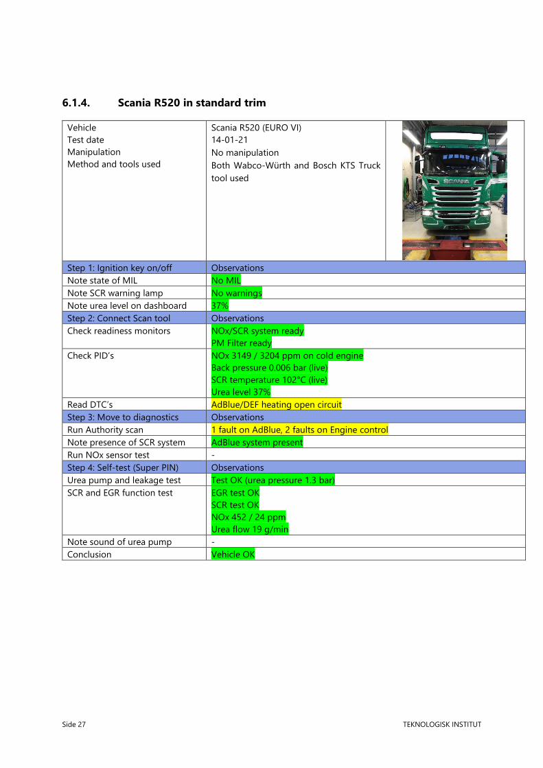
6.1.4. Scania R520 in standard trim
Vehicle
Test date
Manipulation
Method and tools used
Scania R520 (EURO VI)
14-01-21
No manipulation
Both Wabco-Würth and Bosch KTS Truck
tool used
Step 1: Ignition key on/off Observations
Note state of MIL No MIL
Note SCR warning lamp No warnings
Note urea level on dashboard 37%
Step 2: Connect Scan tool Observations
Check readiness monitors NOx/SCR system ready
PM Filter ready
Check PID’s NOx 3149 / 3204 ppm on cold engine
Back pressure 0.006 bar (live)
SCR temperature 102°C (live)
Urea level 37%
Read DTC’s AdBlue/DEF heating open circuit
Step 3: Move to diagnostics Observations
Run Authority scan 1 fault on AdBlue, 2 faults on Engine control
Note presence of SCR system AdBlue system present
Run NOx sensor test -
Step 4: Self-test (Super PIN) Observations
Urea pump and leakage test Test OK (urea pressure 1.3 bar)
SCR and EGR function test EGR test OK
SCR test OK
NOx 452 / 24 ppm
Urea flow 19 g/min
Note sound of urea pump -
Conclusion Vehicle OK

Side 28 TEKNOLOGISK INSTITUT
6.1.5. Scania R520 with software manipulation
Vehicle
Test date
Manipulation
Method and tools used
Scania R520 (EURO VI)
23-01-21
Software: SCR system deactivated by re-
flashing ECU. Physical: SCR controller and
pump power supply disconnected.
Both Wabco-Würth and Bosch KTS Truck
tool used
Step 1: Ignition key on/off Observations
Note state of MIL No MIL
Note SCR warning lamp No warnings
Note urea level on dashboard 37%
Step 2: Connect Scan tool Observations
Check readiness monitors No readiness detected from SCR sensor, while engine is running
Check PID’s No live data from SCR sensor, while engine is running
Read DTC’s -
Step 3: Move to diagnostics Observations
Run Authority scan -
Note presence of SCR system -
Run NOx sensor test -
Step 4: Self-test (Super PIN) Observations
Urea pump and leakage test -
SCR and EGR function test -
Note sound of urea pump -
Conclusion Software manipulation detected by missing live data (data stream) from
NOx-sensor.

Side 29 TEKNOLOGISK INSTITUT
6.1.6. Volvo FH500 in standard trim
Vehicle
Test date
Manipulation
Method and tools used
Volvo FH500 (EURO VI)
02-02-21
No manipulation
Both Wabco-Würth and Bosch KTS Truck
tool used
Step 1: Ignition key on/off Observations
Note state of MIL No MIL
Note SCR warning lamp No warnings
Note urea level on dashboard 25%
Step 2: Connect Scan tool Observations
Check readiness monitors Status of monitored components OK
Check PID’s Back pressure 0 kPa
Urea pressure 1.76 kPa
Read DTC’s Number of stored trouble codes = 0
Step 3: Move to diagnostics Observations
Run Authority scan Scan OK
Note presence of SCR system Exhaust aftertreatment control unit present
Run NOx sensor test -
Step 4: Self-test (Super PIN) Observations
Urea pump and leakage test -
SCR and EGR function test EGR flow 0.16 kg/min
Note sound of urea pump -
Conclusion Vehicle OK
Side 30 TEKNOLOGISK INSTITUT
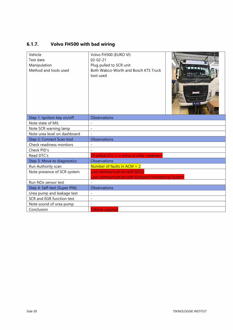
6.1.7. Volvo FH500 with bad wiring
Vehicle
Test date
Manipulation
Method and tools used
Volvo FH500 (EURO VI)
02-02-21
Plug pulled to SCR unit
Both Wabco-Würth and Bosch KTS Truck
tool used
Step 1: Ignition key on/off Observations
Note state of MIL -
Note SCR warning lamp -
Note urea level on dashboard -
Step 2: Connect Scan tool Observations
Check readiness monitors -
Check PID’s -
Read DTC’s 10 active DTC’s in exhaust after treatment
Step 3: Move to diagnostics Observations
Run Authority scan Number of faults in ACM = 2
Note presence of SCR system Lost communication with EECU
Lost communication with Emission Monitoring System
Run NOx sensor test -
Step 4: Self-test (Super PIN) Observations
Urea pump and leakage test -
SCR and EGR function test -
Note sound of urea pump -
Conclusion Vehicle rejected
Side 31 TEKNOLOGISK INSTITUT
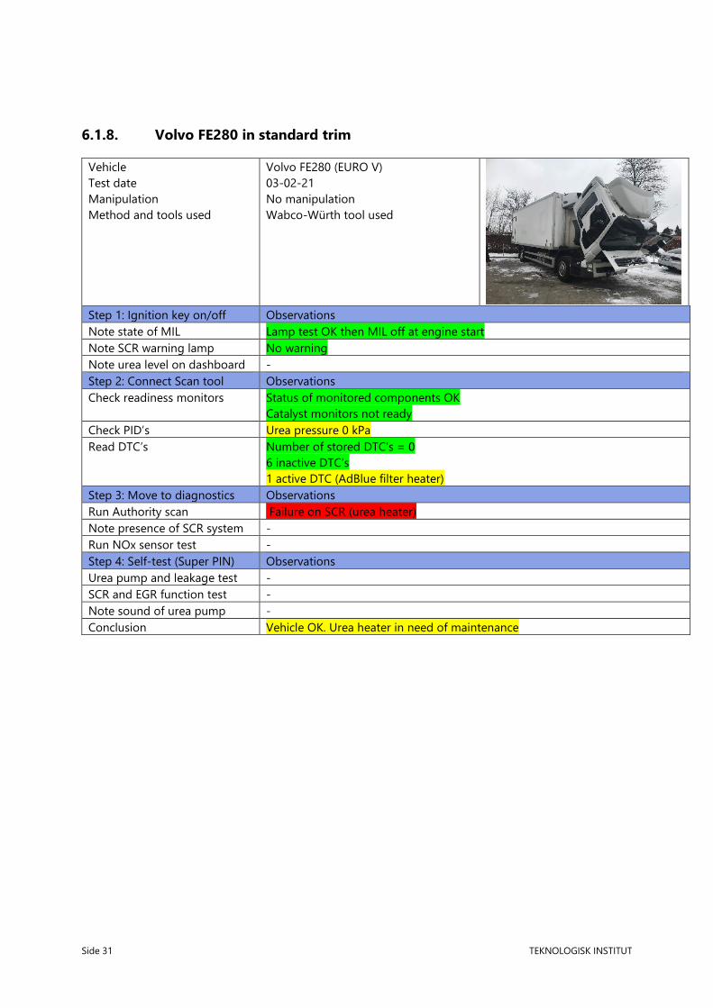
6.1.8. Volvo FE280 in standard trim
Vehicle
Test date
Manipulation
Method and tools used
Volvo FE280 (EURO V)
03-02-21
No manipulation
Wabco-Würth tool used
Step 1: Ignition key on/off Observations
Note state of MIL Lamp test OK then MIL off at engine start
Note SCR warning lamp No warning
Note urea level on dashboard -
Step 2: Connect Scan tool Observations
Check readiness monitors Status of monitored components OK
Catalyst monitors not ready
Check PID’s Urea pressure 0 kPa
Read DTC’s Number of stored DTC’s = 0
6 inactive DTC’s
1 active DTC (AdBlue filter heater)
Step 3: Move to diagnostics Observations
Run Authority scan Failure on SCR (urea heater)
Note presence of SCR system -
Run NOx sensor test -
Step 4: Self-test (Super PIN) Observations
Urea pump and leakage test -
SCR and EGR function test -
Note sound of urea pump -
Conclusion Vehicle OK. Urea heater in need of maintenance

Side 32 TEKNOLOGISK INSTITUT
6.1.9. DAF XE 440 in standard trim
Vehicle
Test date
Manipulation
Method and tools used
DAF XE 440 (EURO VI)
08-02-21
No manipulation
Wabco-Würth tool used
Step 1: Ignition key on/off Observations
Note state of MIL Lamp test OK then MIL off at engine start
Note SCR warning lamp No warning
Note urea level on dashboard 37%
Step 2: Connect Scan tool
Check readiness monitors -
Check PID’s Urea pressure 8.9 bar
Urea level 37.1%
Urea pressure 8.8 bar
NOx 244/231 ppm
DPF Back pressure 7 mbar
AdBlue dosing 588.6 g/h
Read DTC’s No trouble codes stored in system
Step 3: Move to diagnostics
Run Authority scan -
Note presence of SCR system -
Run NOx sensor test -
Step 4: Self-test (Super PIN)
Urea pump and leakage test -
SCR and EGR function test -
Note sound of urea pump -
Conclusion -

Side 33 TEKNOLOGISK INSTITUT
6.1.10. DAF XE 440 with software manipulation
Vehicle
Test date
Manipulation
Method and tools used
DAF XE 440 (EURO VI)
08-02-21
Software: SCR system deactivated by
re-flashing ECU through CAN-bus pro-
tocol (OBD). Physical: SCR pump power
supply disconnected.
Wabco-Würth tool used
Step 1: Ignition key on/off Observations
Note state of MIL Lamp test OK then MIL off at engine start
Note SCR warning lamp No warning for low urea level
Note urea level on dashboard Urea tank level shows 0%
Step 2: Connect Scan tool Observations
Check readiness monitors -
Check PID’s -
Read DTC’s -
Step 3: Move to diagnostics Observations
Run Authority scan -
Note presence of SCR system -
Run NOx sensor test -
Step 4: Self-test (Super PIN) Observations
Urea pump and leakage test -
SCR and EGR function test SCR System check shows no line pressure (“Priming and emptying the AdBlue
system”).
Note sound of urea pump No sound of pump when turning off engine at operating temperature
Conclusion Vehicle rejected due to signs of manipulation

Side 34 TEKNOLOGISK INSTITUT
6.1.11. Iveco Eurocargo 160-280 with software manipulation
Vehicle
Test date
Manipulation
Method and tools used
Iveco Eurocargo 160-280 (EURO VI)
18-02-21
Software: SCR system deactivated by
re-flashing ECU through CAN-bus pro-
tocol (OBD).
Both Bosch KTS and Wabco-Würth
tool used Step 1: Ignition key on/off Observations
Note state of MIL Lamp test OK then MIL off at engine start
Note SCR warning lamp No control light for low urea level
Note urea level on dashboard Urea tank level shows 0%
Step 2: Connect Scan tool Observations
Check readiness monitors -
Check PID’s AdBlue pressure 8990 mbar (in standard trim only)
Read DTC’s Several intermittent faults
Step 3: Move to diagnostics Observations
Run Authority scan -
Note presence of SCR system -
Run NOx sensor test -
Step 4: Self-test (Super PIN) Observations
Urea pump and leakage test Operation failed
SCR and EGR function test SCR System check shows no line pressure.
Note sound of urea pump No sound of urea pump when turning off engine at operating temperature
Conclusion Vehicle rejected due to signs of manipulation

Side 35 TEKNOLOGISK INSTITUT
6.1.12. Mercedes Actros IV 1845 in standard trim
Vehicle
Test date
Manipulation
Method and tools used
Mercedes Actros IV 1845 (EURO VI)
11-03-21
Not possible without physical means
Wabco-Würth tool used
Step 1: Ignition key on/off Observations
Note state of MIL MIL goes on, off, then blinks
MIL lights up for 10 seconds at engine ON
Note SCR warning lamp No urea lamp in dashboard
Display reads “Service immediately”
Note urea level on dashboard Urea gauge shows 30%
Step 2: Connect Scan tool Observations
Check readiness monitors All system read “Ready”
Number of stored DTC’s = 0
Check PID’s Reagent level 33%
Backpressure rises to 0,46 kPa with throttle actuation
Read DTC’s 1 DTC: Adblue resistor heater short
Step 3: Move to diagnostics Observations
Run Authority scan -
Note presence of SCR system -
Run NOx sensor test -
Step 4: Self-test (Super PIN) Observations
Urea pump and leakage test Urea pressure reads 7,9 bar
Metering amount test OK
SCR and EGR function test SCR test OK
Note sound of urea pump Urea pump comes on (audible) then clicks
Conclusion Service warnings and one pending DTC is not enough to incriminate the vehi-
cle. A service is recommended, however

Side 36 TEKNOLOGISK INSTITUT
6.1.13. Mercedes Arcos 2651 in standard trim
Vehicle
Test date
Manipulation
Method and tools used
Mercedes Arcos 2651 (EURO VI)
11-03-21
Not possible without physical means
Wabco-Würth tool used
Step 1: Ignition key on/off Observations
Note state of MIL MIL blinks slowly at Key ON. MIL goes off at engine ON.
Note SCR warning lamp Green urea light comes ON
OBD tester light comes ON
Note urea level on dashboard 1500 km / 30%.
Step 2: Connect Scan tool Observations
Check readiness monitors Some systems not available
Monitored systems read “Yes”
Some systems not ready
Check PID’s Reagent Tank Level 31%
Read DTC’s Several DTC’s overall
1 DTC on ACM “Temperature low”
Stored DTC’s = 0
Step 3: Move to diagnostics Observations
Run Authority scan Several DTC’s overall
1 DTC on ACM
Some tests not carried out
Urea pressure reads 10 bar
MIL cannot be activated
PID $3D DPF Delta Pressure rises with engine RPM, reads
500 Pa = 5 mbar
PID $3D NOx sensor reads 1650 ppm on cold engine
Note presence of SCR system SCR-system present
Run NOx sensor test
Step 4: Self-test (Super PIN) Observations
Urea pump and leakage test Urea pressure reads 9,8 bar
NOx sensors are warming up automatically
SCR and EGR function test
Note sound of urea pump
Conclusion A high number of DTC’s does not incriminate the vehicle. One emission related
DTC is deemed harmless as it is due to temperature.

Side 37 TEKNOLOGISK INSTITUT
6.1.14. Scania R360 in standard trim
Vehicle
Test date
Manipulation
Method and tools used
Scania R360 (EURO V) without DPF/SCR
11-03-21
No manipulation
Wabco-Würth tool used
Step 1: Ignition key on/off Observations
Note state of MIL No MIL at key ON
Note SCR warning lamp Not installed
Note urea level on dashboard Not installed
Step 2: Connect Scan tool Observations
Check readiness monitors Readiness OK, no monitors
Data lists, EGR ready OK
Check PID’s EGR % = 8,7
Read DTC’s DTC = 0
Step 3: Move to diagnostics Observations
Run Authority scan 2 DTC’s on engine management (not emission critical)
Note presence of SCR system AdBlue unit shown in systems but not installed on vehicle
Run NOx sensor test
Step 4: Self-test (Super PIN) Observations
Urea pump and leakage test No test available
SCR and EGR function test No test available
Note sound of urea pump Not installed
Conclusion While the OBD systems differs somewhat from other trucks it does not in-
criminate the vehicle. The manufacturer should be contacted to determine if
the absent MIL is normal.

Side 38 TEKNOLOGISK INSTITUT
6.1.15. Mercedes Actros 3 2548 in standard trim
Vehicle
Test date
Manipulation
Method and tools used
Mercedes Actros 3 2548 (Euro V)
03-02-21
The NOx sensor plug on this vehicle
was pulled to simulate a physical
fault or manipulation.
Wabco-Würth tool used
Step 1: Ignition key on/off Observations
Note state of MIL Lamp test OK then MIL off at engine start
Note SCR warning lamp Urea warning light comes on
Note urea level on dashboard Urea 15%
Step 2: Connect Scan tool Observations
Check readiness monitors Status, readiness OK
Check PID’s No urea tank level
No DPF back pressure
Read DTC’s 2 DTC’s confirmed
Step 3: Move to diagnostics Observations
Run Authority scan Urea tank level 31%
Urea pressure 4,9 bar (live)
NOx ppm invalid (cold engine)
NOx PID invalid (warm engine)
Note presence of SCR system -
Run NOx sensor test -
Step 4: Self-test (Super PIN) Observations
Urea pump and leakage test AdBlue pump test 1,6 bar
Pump is very silent!
SCR activation test shows “active”
NOx sensor self-diagnose shows “OK”
SCR and EGR function test -
Note sound of urea pump -
Conclusion Vehicle is rejected due to the urea warning light, inconsistent pressure and
missing NOx PID on warm engine

Side 39 TEKNOLOGISK INSTITUT
6.1.16. Mercedes Actros IV in standard trim
Vehicle
Test date
Manipulation
Method and tools used
Mercedes Actros IV (Euro VI)
03-02-21
No manipulation
Wabco-Würth tool used
Step 1: Ignition key on/off Observations
Note state of MIL Lamp test OK then MIL off at engine start
Note SCR warning lamp No warning
Note urea level on dashboard Urea 70%
Step 2: Connect Scan tool Observations
Check readiness monitors Readiness OK
Check PID’s Urea 65.5%
Urea pressure 10.034 bar
Back pressure 15 mbar (live)
Upstream NOx 220 ppm
Read DTC’s DTC’s = 0
Step 3: Move to diagnostics Observations
Run Authority scan Aftertreatment OK
Note presence of SCR system ACM (Exhaust aftertreatment system) OK
Metering urea flow rate 5 kg/h only when vehicle is moving
Run NOx sensor test -
Step 4: Self-test (Super PIN) Observations
Urea pump and leakage test -
SCR and EGR function test Urea pressure 10.03 bar
Note sound of urea pump -
Conclusion Vehicle OK

Side 40 TEKNOLOGISK INSTITUT
6.1.17. Actros 1845 with possible faults
Vehicle
Test date
Manipulation
Method and tools used
Mercedes Actros 1845 (Euro VI)
03-02-21
No manipulation
Wabco-Würth tool used
Step 1: Ignition key on/off Observations
Note state of MIL Lamp test OK then MIL off at engine start
Note SCR warning lamp No warning
Note urea level on dashboard Urea level 65%
Step 2: Connect Scan tool Observations
Check readiness monitors -
Check PID’s -
Read DTC’s -
Step 3: Move to diagnostics Observations
Run Authority scan ACM DTC Stored and MIL !!
NOx out shows 0ppm
NOx in shows 0°C
Note presence of SCR system -
Run NOx sensor test NOx sensor test OK
Step 4: Self-test (Super PIN) Observations
Urea pump and leakage test Leak test OK
Urea pressure 4294972 bar !!!
SCR and EGR function test -
Note sound of urea pump -
Conclusion The vehicle is most likely manipulated or malfunctioning.

Side 41 TEKNOLOGISK INSTITUT
6.1.18. Iveco S-Way 570 brand new
Vehicle
Test date
Manipulation
Method and tools used
Iveco S-Way 570 (Euro VI-d)
26-03-21
Not possible to manipulate (too new)
Wabco-Würth tool used
Step 1: Ignition key on/off Observations
Note state of MIL Lamp test OK, then blinking, OFF on engine start
Note SCR warning lamp Lamp is integrated in multifunction display
Note urea level on dashboard 20%
Step 2: Connect Scan tool Observations
Check readiness monitors NOx/SCR aftertreatment not ready
PM Filter ready
NMHC not ready
Exhaust gas sensor ready
Check PID’s Reactant tank level 22.4%
Average demanded regen consumption 0.37 l/h (live)
Back pressure 0.3-0.5 kPa (live)
NOx warning system activation status ‘no’
NOx concentration 65535 ppm (cold)
NOx ppm 130-300 / 65535 (warm)
Distance since DTC clear 655km
Read DTC’s Number of stored trouble codes = 0
Step 3: Move to diagnostics Observations
Run Authority scan Not possible, vehicle too new
Note presence of SCR system Not possible, vehicle too new
Run NOx sensor test Not possible, vehicle too new
Step 4: Self-test (Super PIN) Observations
Urea pump and leakage test Not possible, vehicle too new
SCR and EGR function test Not possible, vehicle too new
Note sound of urea pump Pump sounds for 60 seconds
Conclusion Vehicle OK

Side 42 TEKNOLOGISK INSTITUT
6.1.19. Scania G410 in standard trim
Vehicle
Test date
Manipulation
Method and tools used
Scania G410 DC13 (Euro VI)
25-03-21
No manipulation
Wabco-Würth tool used
Step 1: Ignition key on/off Observations
Note state of MIL Lamp test OK then MIL off at engine start
Note SCR warning lamp No lamp visible in dashboard
Note urea level on dashboard 47%
Step 2: Connect Scan tool Observations
Check readiness monitors NOx/SCR aftertreatment ready
NMHC catalyst ready
Exhaust gas sensor not available
PM Filter ready
Emission system readiness ‘NO’
Check PID’s Urea 47%
Urea 9 bar
Upstream NOx 226 ppm (live)
DPF 0,01 bar (live)
DOC/DPF temp (live)
Read DTC’s Number of stored trouble codes = 0
Step 3: Move to diagnostics Observations
Run Quick/Authority scan AdBlue system, Number of Faults 2 (inactive)
Systems->Antipollution (AdBlue)
Data lists->All->Show->PRINT (OK)
Note presence of SCR system AdBlue system OK
Run NOx sensor test -
Step 4: Self-test (Super PIN) Observations
Urea pump and leakage test Reductant pressure sensor check - pump sounds, 9.8 bar.
SCR and EGR function test Function test SCR 335 C = Active! NOx ppm 585/53, Flow 16 g/min CR 89%
Function test EGR – operation failed
Note sound of urea pump Pump sounds (video clip available)
Conclusion Vehicle OK

Side 43 TEKNOLOGISK INSTITUT
6.1.20. Scania G410 with software manipulation
Vehicle
Test date
Manipulation
Method and tools used
Scania G410 (Euro VI)
26-03-21
ECU flashed, EGR+AdBlue off
Wabco-Würth tool used
Step 1: Ignition key on/off Observations
Note state of MIL Lamp test OK then MIL off at engine start
Note SCR warning lamp No lamp visible in dashboard
Note urea level on dashboard 62%. The gauge reads a fake value which would not rise any concern unless
the true value was known. In the case of this study, however, we knew the true
value and thus knew the reading was fake. As consequence, we have marked it
yellow due to a ‘suspicious’ reading. For an unsuspecting inspector it would
not be noticeable without topping up the urea tank or using other physical in-
spection means to reveal the true level.
Step 2: Connect Scan tool Observations
Check readiness monitors NOx/SCR aftertreatment NOT ready
NMHC catalyst NOT monitored.
Exhaust gas sensor not available
PM Filter NOT ready
Emission system readiness not on list
EGR/VVT system ready (NO, not available)
Check PID’s Urea level 61% (fake). Same concerns as in Step 1.
Urea pressure 9 bar (not live)
Upstream NOx 250 ppm (live)
DPF 0.49 kPa (live)
DOC/DPF temperatures live
Requested quantity of reductant = 0
Pump RPM 1000 (live)
Read DTC’s P203F Reductant kevel ow (true, refilling was just done)
Step 3: Move to diagnostics Observations
Run Authority scan AdBlue system, number of faults 1 (inactive)
Systems->Antipollution (AdBlue)
Data lists->All->Show->PRINT (empty print)
Note presence of SCR system Present
Run NOx sensor test -
Step 4: Self-test (Super PIN) Observations
Urea pump and leakage test Reductant pressure sensor check - pump sounds, 9.6 bar
SCR and EGR function test Function test EGR – operation failed
Function test SCR - Temperature is live - NOx 0 ppm Sensor NOT OK.
Note sound of urea pump Pump sounds
Conclusion Vehicle rejected.

Side 44 TEKNOLOGISK INSTITUT
6.1.21. Scania G410 with emulator ON
Vehicle
Test date
Manipulation
Method and tools used
Scania G410 (Euro VI)
26-03-21
Sercon Emulator installed
Emulator can be switched on/off from
the cockpit.
Wabco-Würth tool used
Step 1: Ignition key on/off Observations
Note state of MIL Lamp test OK then MIL off at engine start
Note SCR warning lamp No lamp visible in dashboard
Note urea level on dashboard 68% (fake). Same concerns as in 6.1.20
Step 2: Connect Scan tool Observations
Check readiness monitors NOx/SCR aftertreatment NOT ready
NMHC catalyst NOT ready
Exhaust gas sensor not available
PM Filter NOT ready
Emission system readiness not on list
EGR/VVT system ready
Check PID’s Urea level not shown
Urea pressure not shown
Upstream NOx 0 ppm (not live)
DPF 0,98 kPa (live)
DPF temperatures (live)
Read DTC’s Number of stored trouble codes = 0
Step 3: Move to diagnostics Observations
Run Authority scan AdBlue system, not present on list
Systems->Antipollution (AdBlue) The vehicle is not responding to the diagnostic
enquire made
Data lists->Not available (AdBLue system)
Note presence of SCR system No communication with EEC / EEC not responding
Run NOx sensor test -
Step 4: Self-test (Super PIN) Observations
Urea pump and leakage test -
SCR and EGR function test Function test EGR – operation failed
Function test SCR Cat temperature fixed at 326 °C (fake value)
Test failed to reach threshold temperature
Note sound of urea pump No sound
Conclusion Vehicle rejected

Side 45 TEKNOLOGISK INSTITUT
6.1.22. Scania G410 with emulator OFF
Vehicle
Test date
Manipulation
Method and tools used
Scania G410 (Euro VI)
26-03-21
Sercon Emulator installed
Emulator can be switched on/off from
the cockpit.
Wabco-Würth tool used
Step 1: Ignition key on/off Observations
Note state of MIL Lamp test OK then MIL off at engine start
Note SCR warning lamp No lamp visible in dashboard
Note urea level on dashboard 46% (true)
Step 2: Connect Scan tool Observations
Check readiness monitors NOx/SCR aftertreatment NOT ready
NMHC catalyst ready
Exhaust gas sensor not available
PM Filter ready
Emission system readiness not on list
EGR/VVT system ready
Check PID’s Screenshot saved (this was done from Step 3)
Urea level 46%
Urea pressure 8.9-9.2 (live)
NOx 3247/3287 ppm
DPF 0.009 bar (live)
DPF temperature 157°C (live)
Read DTC’s Number of stored trouble codes = 0
Step 3: Move to diagnostics Observations
Run Authority scan G-series 2007-2018 (VIN auto detected)
AdBlue system OK
Systems->Antipollution (AdBlue)
Data lists-> All Show OK (no print)
Note presence of SCR system AdBlue system OK
Run NOx sensor test No test without Super PIN
Step 4: Self-test (Super PIN) Observations
Urea pump and leakage test -
SCR and EGR function test Function test EGR – operation failed
Function test SCR, temperature shows correctly
NOx=579/128ppm (live)
Reduction 100%
Note sound of urea pump Sound OK
Conclusion Inconclusive
6.2. Application at Periodical Technical Inspection (PTI).
The method developed in this report may be proposed for future PTI. Step 1 should be part of a PTI as it
is quick and requires no tools. Step 2 is also recommendable as it requires only basic OBD tools and can

Side 46 TEKNOLOGISK INSTITUT
be done in a matter of minutes. Step 3 requires a more advanced OBD tool but otherwise it does not
differ that much from Step 2 because all functions are available on an advanced tool. The main issue is
that the engine must be warmed up for the NOx sensors to activate. Step 4 is the most powerful inspec-
tion tool, but also the most time consuming. It could add significantly to the cost of PTI if implemented.
Step 2-4 also requires significant skills from the operator. The PTI official is therefore an important part
of the method. With enough experience and training the PTI official will be able to distinguish important
OBD data from less important ones. It would be tempting to simply count the number of red and yellow
flags, but the inspections done in section 6.1 do not provide sufficient confidence in such approach. The
decision on whether to reject a vehicle at future PTI’s should be further elaborated.
7. Conclusion
The combination of an OBD diagnostics tool with a skilled operator can be used effectively to detect faulty
or manipulated emissions system on heavy trucks.
A step-by-step method has been provided in this report. The method clearly detects mechanical and
electrical faults. Even though the method also can strongly indicate illegal manipulation, the final proof
should include physical signs, such as missing/disconnected sensors and plugs, or be verified in a spe-
cialized workshop.
The relatively clear signs of manipulated or malfunctioning systems are:
• MIL stays on while engine is running
• Urea warning light stays on
• Urea gauge reads 0%
• SCR System check shows no line pressure.
• No live data/readiness detected from SCR sensor, while engine is running.
• Urea system or complete ACM system missing from EOBD
• Self-test on SCR system failed
• Urea leak test failed
• NOx PID shows a fixed value not moving with warm engine
• Back pressure PID not moving with throttle actuation
• No change in urea pump pressure at engine shutdown
Other tell-tell signs:
• Urea level PID not matching dashboard reading
• MIL blinking
Signs which should be neglected:
• Pending DTC’s
• Readiness monitors that read “incomplete.”

Side 47 TEKNOLOGISK INSTITUT
• Missing self-test functions
• Silent running urea pumps if pressure reads OK
8. Nomenclature
ACM (Active Control Module) - a submenu in Wabco-Würth tester
AdBlue – a commercial name for urea
DEF (Diesel Exhaust Fluid) – a name used for urea, AdBlue, reagent, reductant
de-NOX – general term for systems for removal of NOX
DLC (Data Link Connector) – a name for the OBD-plug
DOC
DPF (Diesel particulate Filter) – a system that reduces soot and other particulate emissions
ECU (Engine Control Unit) – an on-board computer that controls the engine
EEC (Exhaust Emission Control) - a submenu in Wabco-Würth tester
EGR (Exhaust Gas Recirculation) – a system used to reduce NOX emissions
EGS (Exhaust Gas Sensor) – a sensor in the exhaust system
Emission Reduction – common term for filters, catalysts etc. on vehicles
IUPRs (In-Use Performance Ratios) – internal self-check values in the OBD
MIL (Malfunction Indicator Lamp) – a generic dash board light that turns on in case of emission-critical
conditions detected by the OBD
NMHC Catalyst (Non-Methane Hydro Carbon) – synonym for ammonia slip catalyst
NOx (Nitrogen Oxides) – harmful exhaust gases that cause smog, acidification, and respiratory problems
OBD (On-Board Diagnostics) – a system that detects fault on vehicle systems and allows communication
with vehicle control units
OEM (Original Equipment Manufacturer) – Vehicle manufacturers and their direct sub-suppliers
PM Filter (Particulate Matter Filter) – synonym for DPF
PTI (Periodical Technical Inspection) – Mandatory vehicle inspections also known as ’MOT’
Reagent – a common name used for urea, AdBlue, reductant or DEF
RPM (Revolutions Per Minute) – a measure of engine speed
SCR (Selective Catalytic Reduction) – a type of catalyst for NOX reduction
Super PIN – a speciel activitation code needed for some vehicle self-test functions on Wabco-Würth
Urea – a reagent used in SCR catalysts
WHTC (World Harmonized Test Cycle) – a type approval test cycle for truck engines
9. Literature list
1. Frandsen, Sten: “Investigation of NOx manipulation in heavy-duty vehicles - Screening of emula-
tor devices and potential control methods to detect NOx manipulation”, March 2018, TS2060107-
007877
2. International Counsil for Clean Transportation: ”GLOBAL OVERVIEW OF ON-BOARD DIAGNOSTIC
(OBD) SYSTEMS FOR HEAVY-DUTY VEHICLES”
Side 48 TEKNOLOGISK INSTITUT
3. Vehicle Emissions On-Board Diagnostics (OBD) | State and Local Transportation Resources | US
EPA
4. Transportpolicy.net
5. Tables 1 to 4 in Appendix 5 of Annex 9B to R49
6. UNECE Global Technical Regulation no. 5 (WWH-OBD) Section 4.5
7. SAE J1979/ISO 15031-5 “Road vehicles — Communication between vehicle and external equip-
ment for emissions-related diagnostics — Part 5: Emissions-related diagnostic services”


![Heavy Trucks Buses Catalogue Eng Tcm795-1611335[1]](https://img.pdfslide.net/doc/110x75/54e815624a7959397d8b4dcd/heavy-trucks-buses-catalogue-eng-tcm795-16113351.jpg)