Embed Size (px)
Citation preview
April 2012 PKG-SVX19B-E4
Mercury Close Control Unit
Direct Expansion UnitEDAB / EUAB / EDAV / EUAV / EDWB / EUWB / EDWV / EUWV1105-1106-2107-2207-2109-2209-2111-2211-2113-2213-2216-2218-2222-4222-2225-4225-4228
Chilled Water UnitEDCB / EUCB / EDCV / EUCV0070-0100-0120-0170-0200-0250-0270-0340-0400
Technical guide

PKG-SVX19B-E42
3PKG-SVX19B-E4
GENERAL INSTRUCTIONS 4Information contained in the manual 4Symbols 4Storage 4Storage after use 4Disposal 4Disposal of the machine 4
SAFETY 6General Instructions 6Warning for lifting and transportation 6Warnings for installation 6Intended use 6Warnings for use 6Safety during maintenance work 6
INTRODUCTION 7Presentation of the system 7
MERCURY - DIRECT EXPANSION 10Technical characteristics 10Operating description 13Name and description of the main components 14Checks to be made on delivery 17Unloading the unit 17Characteristics of the installation area 17Positioning of the unit 17Door opening and removal of the panels 18Door opening 18Internal protection panels 19Electrical connections 20Connection to the drains 21Connection to the gas drain 21Refrigerant connections on air cooled units 22Choosing the diameter of the discharge tube 22
R410A 23BACKFLOW LINE DIMENSIONING (LIqUID) 26
Type of oil recommended with MANEUROP compressors 28Type of oil recommended with SANYO compressors 28Type of oil recommended with Scrolltech HCJ 072-HLJ 083 compressors 28Connection for water cooled units 29
MANUAL START UP AND SHUT DOWN OF THE UNIT 30SETTING AND ADJUSTMENT 31
Selecting the power supply of the fans 31Setting the regulation and safety devices 34Setting the pressostatic valve (optional on chilled water cooled models only) 34Setting the air flow sensor 34Setting the dirty filter sensors 35
MAINTENANCE 35Check every three months 35Check every six months 35Annual checks 35Checks to be performed every sixty months 35
Cleaning and replacing the filters 36Troubleshooting 37
MERCURY - CHILLED WATER 41Technical characteristics 41Operating description 42Name and description of the main components 43Checks to be made on delivery 45Unloading the unit 45Characteristics of the installation area 45Positioning of the unit 46Opening of the door and removal of the panels 46Internal protection panels 47Electrical connections 48Connection to the water drain 49Hydraulic connections 50Filling the hydraulic circuit 50Filling the primary circuit 50 Filling the hydraulic circuits of the conditioners 50
MANUAL START UP AND SHUT DOWN OF THE UNIT 51SETTING AND ADJUSTMENT 52
Selecting the power supply of the fans 52Setting the regulation and safety devices 56Setting the air flow sensor 57Setting the dirty filter sensors 57
MAINTENANCE 57Check every three months 57Check every six months 57Annual checks 57Cleaning and replacing the filters 58Servomotor and chilled water valve 59Servomotor and hot water valve 59Troubleshooting 60
ACCESSORIES 62Humidifier 62
Operating principle 63Feed water 63Connections 63
Maintenance 64Electric heaters 65Temperature and humidity sensor 66Connection to fresh air intake 67
Maintenance 68Discharge temperature threshold sensor (only on CHILLED WATER models) 68
Contents
PKG-SVX19B-E44
GENERAL INSTRUCTIONSInformation contained in the manualThe present manual describes the Mercury conditioning units. It supplies general information and safety instructions, unit transportation and installation information, as well as necessary information about how to use the units.It is an integral part of the product.The descriptions and illustrations in this manual are unbinding; Trane reserves the right to make any alterations it sees fit in order to improve the product without having to update this document.The illustrations and images in this manual are examples only and may differ from practical situations.SymbolsThe following graphic and linguistic symbols have been used in this manual:
WARNING! This message may appear before certain procedures. Failure to observe this message may cause damage to equipment.WARNING! This message may appear before certain procedures. Failure to observe this message may cause injury to the operators and damage the equipment.
StorageThe following conditions must be respected should the unit require storing for a given period of time: The packing must be kept intact.The place of storage must be dry (<85% R.H.) and protected against the sun (temperature <50°C).Storage after useThe unit must be packaged when stored for a long time.DisposalThe unit is mainly made of recyclable materials which should be separated from the rest of the unit before it is disposed. When disposing of the gas and oil inside the refrigerating circuit, consult a specialist company.Disposal of the machineThe following instructions deal with the disposal of Trane machines.The procedures described below are guidelines only, provided to make the machine disassembling easier. The purpose of these operations is to achieve homogeneous material quantities for disposal or recycling.These instructions are followed by a list of the possible typical CER 2002 codes to allow an easier disposal of the machine parts.
WARNING! Observe the safety precautions at work wearing the suitable individual protection devices (IPD) and using the appropriate equipments.WARNING! Maintenance and service operations (disassembling included) must be performed by qualified and expert personnel, aware of the essential precautions.
Preliminary oPerationsPower supply and data processing system:• Turn the machine off and unplug it from the power supply
and from the communication system.WARNING! The circuits can be pressurised; any maintenance and service operation must only be carried out by expert and qualified personnel, aware of the essential safety precautions. WARNING! The machine can contain hot water: adopt all of the essential safety cautions.
Hydraulic circuit:• Drain the hydraulic circuit and disconnect the hydraulic
line.Refrigerating circuit:• Purge the refrigeration system with suitable recovery
equipments to avoid gas leakage in the environment.Disassembling the machineThe following paragraphs describe the main macrocomponents to facilitate the disassembling, disposal and recycling of materials with appropriate features.To disassemble the machine properly, follow the guidelines provided below.• ELECTRICAL PANEL Remove the electrical panel and dispose its parts
following the procedures provided by the relevant standards. The models equipped with a «clock board» in the electrical panel have a service battery which must be disposed separately.
- Materials: electronic parts, electrical cables, metal and plastic supports, batteries.
• COVER PANELS Remove the metal cover and protection panels of the
machine. The panels can be made of polypaired materials, that
is insulating material together with metal. In this case, separate the different elements.
- Materials: galvanized sheet, aluminium, soundproof panels: expanded polyurethane, thermoinsulating panels: mineral wool.
• AIR FILTERS Remove the air filters. - Materials: metallic net, synthetic fibre.
5PKG-SVX19B-E4
• FINNED COIL Remove the finned coils from the machine. - Materials: copper, aluminium, steel.• HUMIDIFIER If a humidifier is installed, remove it. - Materials: polypropylene, iron materials. • ELECTRO-MECHANICAL PARTS Find and remove valves, electro-mechanical and
electronic parts (three-way valves, sensors, etc.) from the machine.
• RESISTANCES Remove the resistances if they are installed. - Materials: aluminium, inseparable copper + magnesium
oxide.• PIPES AND PARTS OF THE REFRIGERATING
CIRCUIT Find the connection pipes installed in the machine and
separate them from the other elements. Pipes can be caulked: in this case, before recovery,
separate the insulating material from the metal pipe. Even the elements of the refrigerating circuit are
considered as pipes: joints or valves. - Materials: copper, brass, cast iron, steel and plastic.• PUMP Remove the pump from the machine. - Materials: pump.• CONDENSER Remove the condenser, if installed. The condenser contains the elements of a machine,
equipped with a small electrical panel, fans and a thermal exchange battery, usually characterized by aluminium structure and feet made of varnished steel.
- Materials: electrical elements, aluminium, steel (varnished).
• BRAZED PLATE EXCHANGER If installed, remove the brazed plate exchanger. - Materials: INOX AISI braze welding, with an alloy
containing a large amount of silver.• FANS Remove the fans. Disassemble the metal frame and
proceed with the recycling of the metal alloy. - Materials: electro-mechanical elements, iron wrecks.
WARNING! The fans of some machine models are integral part of the carrying structure. Removing the fans can compromise the stability of the frame. We recommend to pay attention during disassembling operations.
• COMPRESSORS AND LIQUID SEPARATORSWARNING! Pay attention to oil contained in the compressors. Avoid any loss of oil during operations. If possible, dispose of oil and compressors separately.
Finally remove the liquid separators and the compressors from the machine base.
- Materials: liquid separators and compressors• METAL BASE Proceed with the recycling of the metal base. - Materials: galvanised sheet.
WARNING! Waste deriving from machine disassembly must be disposed of and classified according to CER codes only consulting authorised and specialist companies.
The following chart contains a partial list of the typical CER codes applied to waste deriving from disassembling, so it must be considered just as an indication.
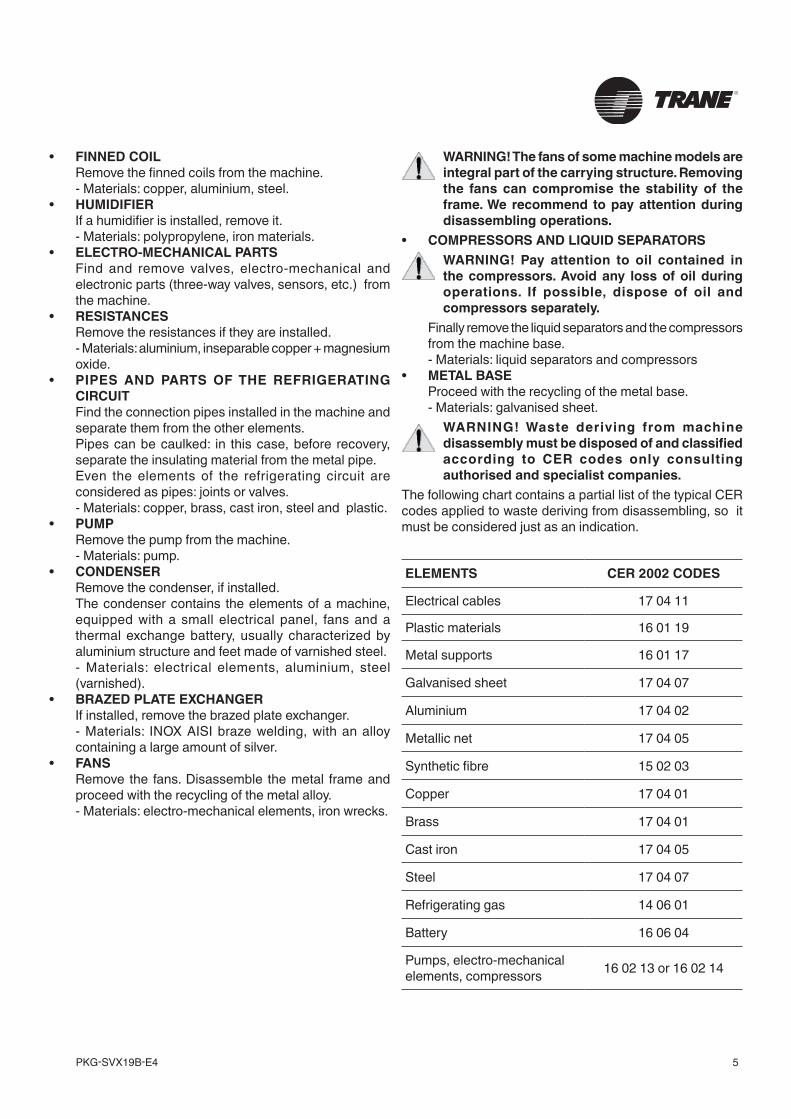
ELEMENTS CER 2002 CODES
Electrical cables 17 04 11
Plastic materials 16 01 19
Metal supports 16 01 17
Galvanised sheet 17 04 07
Aluminium 17 04 02
Metallic net 17 04 05
Synthetic fibre 15 02 03
Copper 17 04 01
Brass 17 04 01
Cast iron 17 04 05
Steel 17 04 07
Refrigerating gas 14 06 01
Battery 16 06 04
Pumps, electro-mechanical elements, compressors 16 02 13 or 16 02 14
PKG-SVX19B-E46
SAFETYGeneral Instructions
WARNING! Removal of, or tampering with, safety devices is a violation of EUROPEAN SAFETY STANDARDS.WARNING! During installation authorised personnel must wear individual safety devices.
Trane will only consider itself responsible for the safety, reliability and performance of the machine if:• repair work has only been carried out by authorised personnel;• the electric installation conforms to the standards currently in force;• the devices are used in conformity with the relative instructions.Carefully read this instruction manual before carrying out any kind of use or maintenance work on the units.Installation, maintenance and use must be carried out respecting all of the work safety standards.The operator responsible for the above mentioned services must be suitably specialised and possess expert knowledge of the devices.Trane refuses all responsibility for damage to people or objects due to the inobservance of the safety standards.Warning for lifting and transportationLifting and transportation of the units must be carried out by specialised personnel as described in the relative paragraphs.The load must always be solidly anchored to the bearing element of the lifting equipment and means of transport. No-one must remain near the suspended load, nor in the working area of the crane, forklift truck or any other lifting equipment or means of transport. Adopt all of the cautions provided by the relevant safety standards, in order to prevent any possible damage to people or objects.Warnings for installationAny type of work on the electrical installation must only be carried out by specialised technicians who are experts in this field.Specialised technical personnel must use appropriate equipment when checking the grounding of devices.Installation may only take place in locations where there is NO public access.Intended useMercury air conditioning units have been designed and produced to carry out air conditioning, within the limits and methods described in the present manual. The air conditioners must be used exclusively in internal environments.No modifications may be made to the units or their parts without explicit written consent from Trane.
Warnings for useOnly use the machinery for the purpose for which it was designed and manufactured.Environmental limits for useThe environmental conditions for the use of Mercury air conditioners must fall within the following values:• Tmin=18°C • Tmax=30°C• %rHmin=30% • %rHmax=70%Safety during maintenance workAll repair work must be carried out by professionally qualified personnel authorised by Trane.Unplug the machine form the power supply before starting any maintenance work.While drawing up this manual, we have considered all of the operations which are part of normal maintenance operations. N.B. Do not carry out any work which has not been specified in this manual.
7PKG-SVX19B-E4
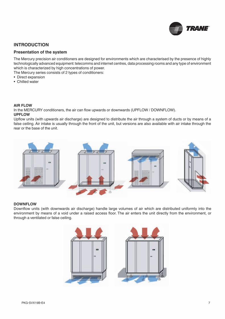
AIR FLOWIn the MERCURY conditioners, the air can flow upwards or downwards (UPFLOW / DOWNFLOW).UPFLOWUpflow units (with upwards air discharge) are designed to distribute the air through a system of ducts or by means of a false ceiling. Air intake is usually through the front of the unit, but versions are also available with air intake through the rear or the base of the unit.
INTRODUCTIONPresentation of the systemThe Mercury precision air conditioners are designed for environments which are characterised by the presence of highly technologically advanced equipment: telecomms and internet centres, data processing rooms and any type of environment which is characterized by high concentrations of power.The Mercury series consists of 2 types of conditioners:• Direct expansion• Chilled water
DOWNFLOWDownflow units (with downwards air discharge) handle large volumes of air which are distributed uniformly into the environment by means of a void under a raised access floor. The air enters the unit directly from the environment, or through a ventilated or false ceiling.
PKG-SVX19B-E48
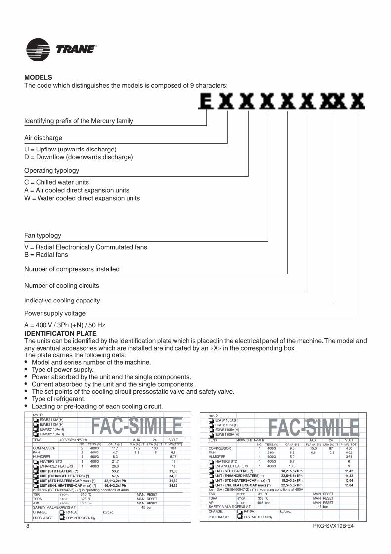
IDENTIFICATON PLATEThe units can be identified by the identification plate which is placed in the electrical panel of the machine. The model and any eventual accessories which are installed are indicated by an «X» in the corresponding boxThe plate carries the following data:• Model and series number of the machine.• Type of power supply.• Power absorbed by the unit and the single components.• Current absorbed by the unit and the single components.• The set points of the cooling circuit pressostatic valve and safety valve.• Type of refrigerant.• Loading or pre-loading of each cooling circuit.
MODELSThe code which distinguishes the models is composed of 9 characters:
Identifying prefix of the Mercury family
Air dischargeU = Upflow (upwards discharge)D = Downflow (downwards discharge)
Operating typologyC = Chilled water unitsA = Air cooled direct expansion unitsW = Water cooled direct expansion units
Fan typologyV = Radial Electronically Commutated fansB = Radial fans
Indicative cooling capacity
Number of compressors installed
Number of cooling circuits
Power supply voltageA = 400 V / 3Ph (+N) / 50 Hz
8
Identifying prefix of the Mercury family
Air discharge
U = Upflow (upwards discharge)D = Downflow (downwards discharge)
Operating typology
C = Chilled water unitsA = Air cooled direct expansion unitsW = Water cooled direct expansion units
Fan typology
V = Radial Electronically Commutated fansB = Radial fans
MODELSThe code which distinguishes the models is composed of 9 characters:
IDENTIFICATON PLATEThe units can be identified by the identification plate which is placed in the electrical panel of the machine. The model andany eventual accessories which are installed are indicated by an "X" in the corresponding boxThe plate carries the following data:• Model and series number of the machine.• Type of power supply.• Power absorbed by the unit and the single components.• Current absorbed by the unit and the single components.• The set points of the cooling circuit pressostatic valve and safety valve.• Type of refrigerant.• Loading or pre-loading of each cooling circuit.
Indicative cooling capacity
Number of compressors installed
Number of cooling circuits
Power supply voltage
A = 400 V / 3Ph (+N) / 50 Hz
rev. D
EDAB2113A(H) SERIAL No.
EUAB2113A(H)
EDWB2113A(H)
EUWB2113A(H)
TLOV42.XUAzH05/N+hP3/V004.SNET
NO. TENS. (V) OA (A) [/1] FLA (A) [/1] LRA (A) [/1] P (kW) [TOT]
COMPRESSOR 2 400/3 11,1 17,2 100 10,4
6,5513,57,43/0042NAF
HUMIDIFIER 1 400/3 8,3 0,0 0 5,77
HEATERS STD 1 400/3 21,7 0,0 0 15
ENHANCED HEATERS 1 400/3 26,0 0,0 0 18
00,132,35)*( )SRETAEH DTS( TINU
00,435,75)*( )SRETAEH DECNAHNE( TINU
26,13hP1x2,3+1,24)*( )xam PAC+SRETAEH DTS( TINU
26,43hP1x2,3+4,64)*( )xam PAC+SRETAEH .HNE( TINU
Icu=15kA (CEI EN 60947-2) / (*) in operating conditions at 400V
TSR STOP: 310 °C MAN. RESET
TSRA STOP: 328 °C MAN. RESET
AP1 STOP: TESER.NAMrab5,04
rab54:TA SNEPO EVLAV YTEFAS
CHARGE: R410A kg/circ.
PRECHARGE: DRY NITROGEN N2
rev. D
EDAB1105A(H) SERIAL No.
EUAB1105A(H)
EDWB1105A(H)
EUWB1105A(H)
LOV42.XUAzH05/N+hP3/V004.SNET T
NO. TENS. (V) OA (A) [/1] FLA (A) [/1] LRA (A) [/1] P (kW) [TOT]
COMPRESSOR 1 400/3 9,5 15,0 87 4,50
29,05,216,65,51/0321NAF
HUMIDIFIER 1 400/3 5,2 0,0 0 3,61
HEATERS STD 1 400/3 8,7 0,0 0 6
ENHANCED HEATERS 1 400/3 13,0 0,0 0 9
24,11hP1x5,5+2,81)*( )SRETAEH DTS( TINU
24,41hP1x5,5+5,22)*( )SRETAEH DECNAHNE( TINU
40,21hP1x5,5+2,81)*( )xam PAC+SRETAEH DTS( TINU
40,51hP1x5,5+5,22)*( )xam PAC+SRETAEH .HNE( TINU
Icu=15kA (CEI EN 60947-2) / (*) in operating conditions at 400V
TSR STOP: 310 °C MAN. RESET
TSRA STOP: 328 °C MAN. RESET
AP STOP: ESER.NAMrab5,04 T
rab54:TA SNEPO EVLAV YTEFAS
CHARGE: R410A kg/circ.
PRECHARGE: DRY NITROGEN N2
FAC-SIMILE FAC-SIMILE
9PKG-SVX19B-E4
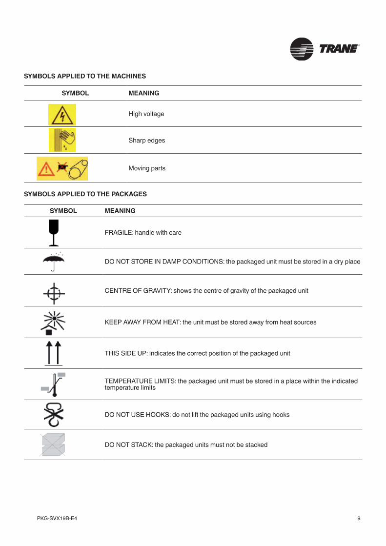
SYMBOLS APPLIED TO THE MACHINES
SYMBOL MEANING
High voltage
Sharp edges
Moving parts
SYMBOL MEANING
FRAGILE: handle with care
DO NOT STORE IN DAMP CONDITIONS: the packaged unit must be stored in a dry place
CENTRE OF GRAVITY: shows the centre of gravity of the packaged unit
KEEP AWAY FROM HEAT: the unit must be stored away from heat sources
THIS SIDE UP: indicates the correct position of the packaged unit
TEMPERATURE LIMITS: the packaged unit must be stored in a place within the indicated temperature limits
DO NOT USE HOOKS: do not lift the packaged units using hooks
DO NOT STACK: the packaged units must not be stacked
SYMBOLS APPLIED TO THE PACKAGES
PKG-SVX19B-E410
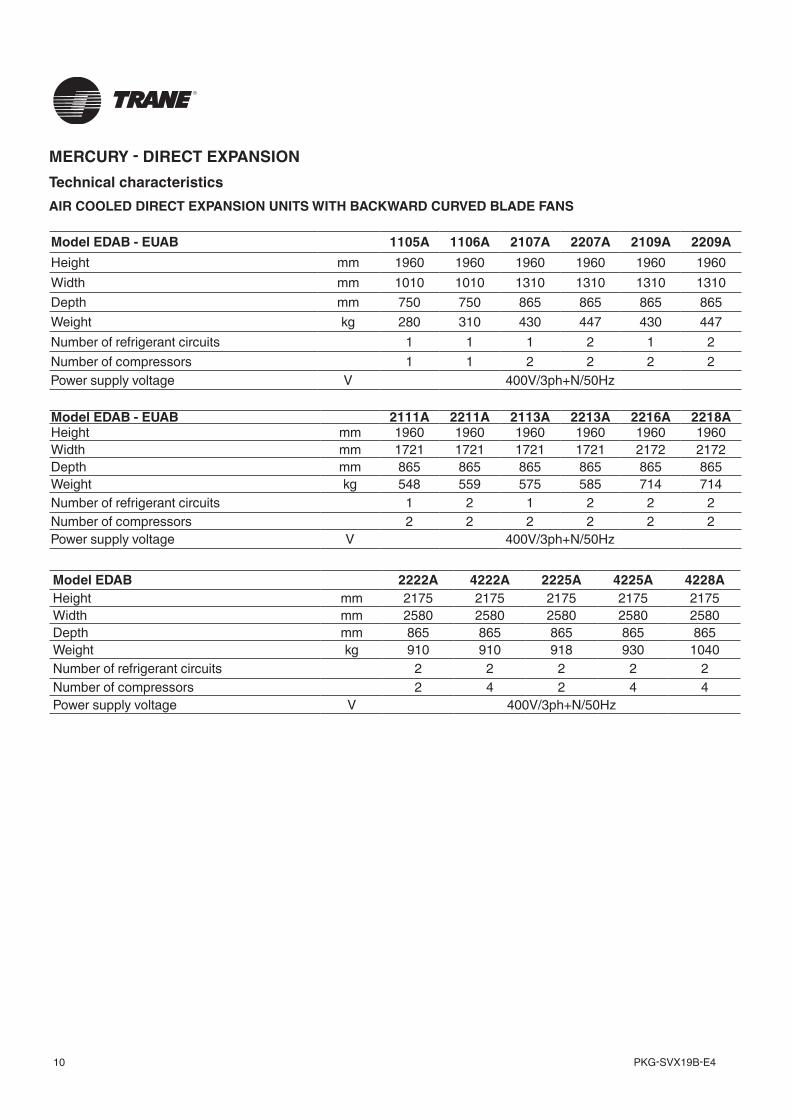
MERCURY - DIRECT EXPANSIONTechnical characteristicsAIR COOLED DIRECT EXPANSION UNITS WITH BACKWARD CURVED BLADE FANS
Model EDAB - EUAB 1105A 1106A 2107A 2207A 2109A 2209AHeight mm 1960 1960 1960 1960 1960 1960Width mm 1010 1010 1310 1310 1310 1310Depth mm 750 750 865 865 865 865Weight kg 280 310 430 447 430 447Number of refrigerant circuits 1 1 1 2 1 2Number of compressors 1 1 2 2 2 2Power supply voltage V 400V/3ph+N/50Hz
Model EDAB - EUAB 2111A 2211A 2113A 2213A 2216A 2218AHeight mm 1960 1960 1960 1960 1960 1960Width mm 1721 1721 1721 1721 2172 2172Depth mm 865 865 865 865 865 865Weight kg 548 559 575 585 714 714Number of refrigerant circuits 1 2 1 2 2 2Number of compressors 2 2 2 2 2 2Power supply voltage V 400V/3ph+N/50Hz
Model EDAB 2222A 4222A 2225A 4225A 4228AHeight mm 2175 2175 2175 2175 2175Width mm 2580 2580 2580 2580 2580Depth mm 865 865 865 865 865Weight kg 910 910 918 930 1040Number of refrigerant circuits 2 2 2 2 2Number of compressors 2 4 2 4 4Power supply voltage V 400V/3ph+N/50Hz
11PKG-SVX19B-E4
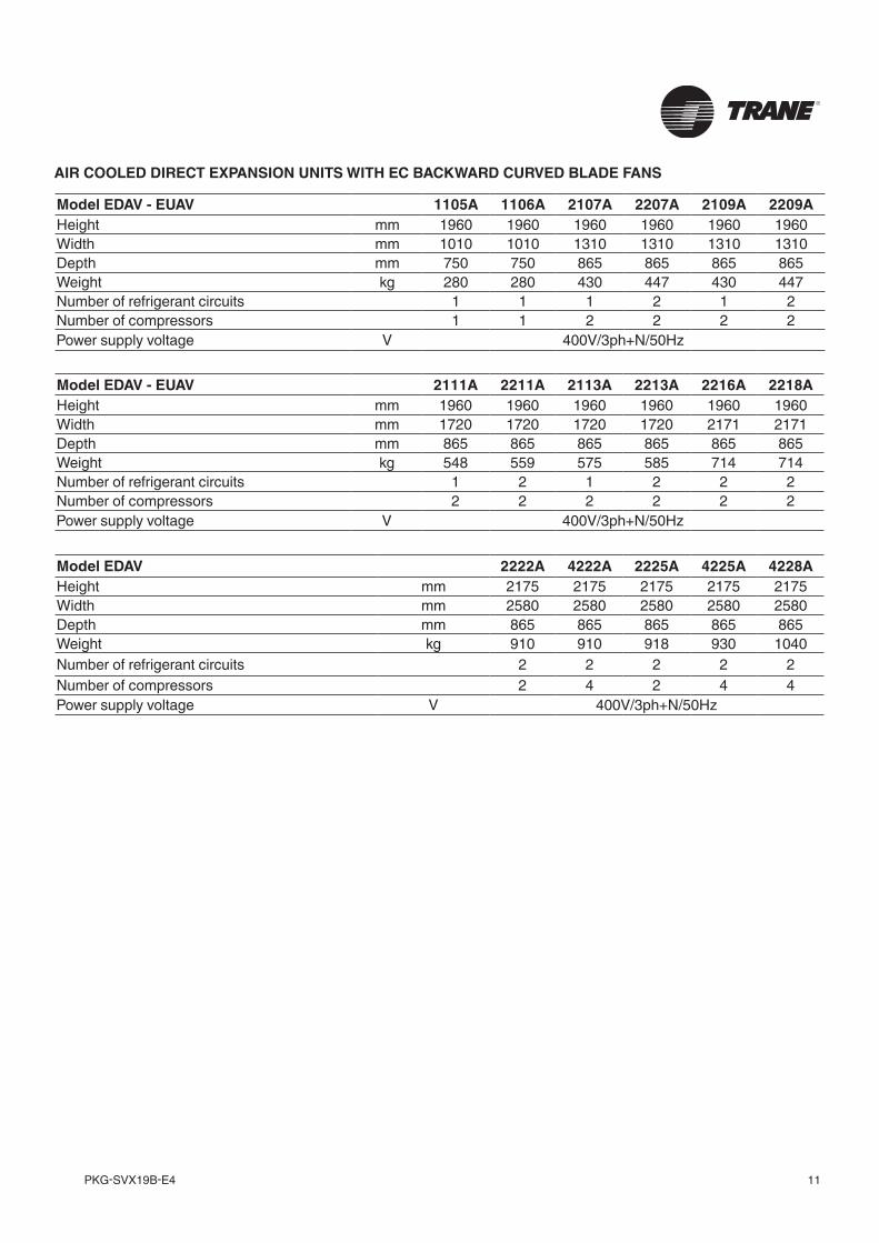
Model EDAV - EUAV 1105A 1106A 2107A 2207A 2109A 2209AHeight mm 1960 1960 1960 1960 1960 1960Width mm 1010 1010 1310 1310 1310 1310Depth mm 750 750 865 865 865 865Weight kg 280 280 430 447 430 447Number of refrigerant circuits 1 1 1 2 1 2Number of compressors 1 1 2 2 2 2Power supply voltage V 400V/3ph+N/50Hz
AIR COOLED DIRECT EXPANSION UNITS WITH EC BACKWARD CURVED BLADE FANS
Model EDAV - EUAV 2111A 2211A 2113A 2213A 2216A 2218AHeight mm 1960 1960 1960 1960 1960 1960Width mm 1720 1720 1720 1720 2171 2171Depth mm 865 865 865 865 865 865Weight kg 548 559 575 585 714 714Number of refrigerant circuits 1 2 1 2 2 2Number of compressors 2 2 2 2 2 2Power supply voltage V 400V/3ph+N/50Hz
Model EDAV 2222A 4222A 2225A 4225A 4228AHeight mm 2175 2175 2175 2175 2175Width mm 2580 2580 2580 2580 2580Depth mm 865 865 865 865 865Weight kg 910 910 918 930 1040Number of refrigerant circuits 2 2 2 2 2Number of compressors 2 4 2 4 4Power supply voltage V 400V/3ph+N/50Hz
PKG-SVX19B-E412
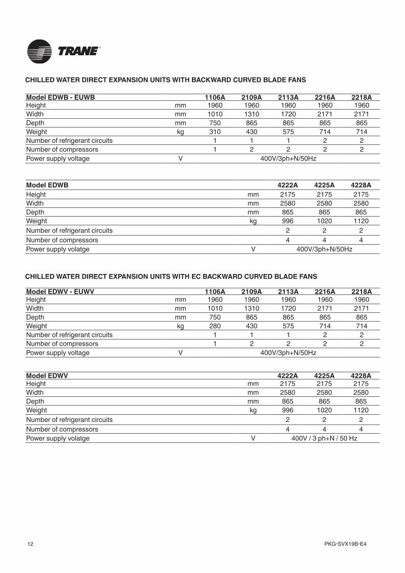
CHILLED WATER DIRECT EXPANSION UNITS WITH EC BACKWARD CURVED BLADE FANS
Model EDWV - EUWV 1106A 2109A 2113A 2216A 2218AHeight mm 1960 1960 1960 1960 1960Width mm 1010 1310 1720 2171 2171Depth mm 750 865 865 865 865Weight kg 280 430 575 714 714Number of refrigerant circuits 1 1 1 2 2Number of compressors 1 2 2 2 2Power supply voltage V 400V/3ph+N/50Hz
Model EDWV 4222A 4225A 4228AHeight mm 2175 2175 2175Width mm 2580 2580 2580Depth mm 865 865 865Weight kg 996 1020 1120Number of refrigerant circuits 2 2 2Number of compressors 4 4 4Power supply volatge V 400V / 3 ph+N / 50 Hz
CHILLED WATER DIRECT EXPANSION UNITS WITH BACKWARD CURVED BLADE FANS
Model EDWB - EUWB 1106A 2109A 2113A 2216A 2218AHeight mm 1960 1960 1960 1960 1960Width mm 1010 1310 1720 2171 2171Depth mm 750 865 865 865 865Weight kg 310 430 575 714 714Number of refrigerant circuits 1 1 1 2 2Number of compressors 1 2 2 2 2Power supply voltage V 400V/3ph+N/50Hz
Model EDWB 4222A 4225A 4228AHeight mm 2175 2175 2175Width mm 2580 2580 2580Depth mm 865 865 865Weight kg 996 1020 1120Number of refrigerant circuits 2 2 2Number of compressors 4 4 4Power supply volatge V 400V/3ph+N/50Hz
13PKG-SVX19B-E4
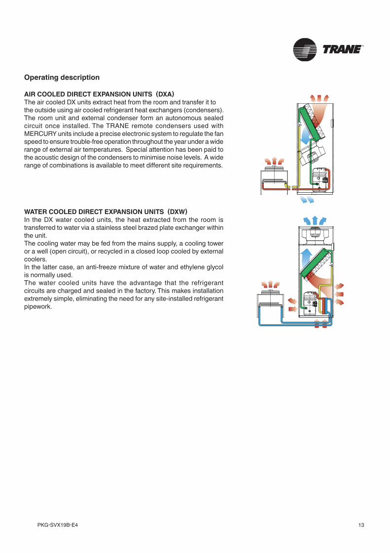
AIR COOLED DIRECT EXPANSION UNITS (DXA)The air cooled DX units extract heat from the room and transfer it to the outside using air cooled refrigerant heat exchangers (condensers). The room unit and external condenser form an autonomous sealed circuit once installed. The TRANE remote condensers used with MERCURY units include a precise electronic system to regulate the fan speed to ensure trouble-free operation throughout the year under a wide range of external air temperatures. Special attention has been paid to the acoustic design of the condensers to minimise noise levels. A wide range of combinations is available to meet different site requirements.
WATER COOLED DIRECT EXPANSION UNITS (DXW)In the DX water cooled units, the heat extracted from the room is transferred to water via a stainless steel brazed plate exchanger within the unit.The cooling water may be fed from the mains supply, a cooling tower or a well (open circuit), or recycled in a closed loop cooled by external coolers.In the latter case, an anti-freeze mixture of water and ethylene glycol is normally used.The water cooled units have the advantage that the refrigerant circuits are charged and sealed in the factory. This makes installation extremely simple, eliminating the need for any site-installed refrigerant pipework.
Operating description
13
AIR COOLED DIRECT EXPANSION UNITS (DXA)The air cooled DX units extract heat from the room and transfer it tothe outside using air cooled refrigerant heat exchangers (condensers).The room unit and external condenser form an autonomous sealed circuitonce installed. The TRANE remote condensers used with MERCURYunits include a precise electronic system to regulate the fan speed toensure trouble-free operation throughout the year under a wide range ofexternal air temperatures. Special attention has been paid to the acousticdesign of the condensers to minimise noise levels. A wide range ofcombinations is available to meet different site requirements.
WATER COOLED DIRECT EXPANSION UNITS (DXW)In the DX water cooled units, the heat extracted from the room istransferred to water via a stainless steel brazed plate exchanger withinthe unit.The cooling water may be fed from the mains supply, a cooling tower ora well (open circuit), or recycled in a closed loop cooled by externalcoolers.In the latter case, an anti-freeze mixture of water and ethylene glycol isnormally used.The water cooled units have the advantage that the refrigerant circuitsare charged and sealed in the factory. This makes installation extremelysimple, eliminating the need for any site-installed refrigerant pipework.
Operating description
PKG-SVX19B-E414
AC
H
E
D
F
G
DE
F
G
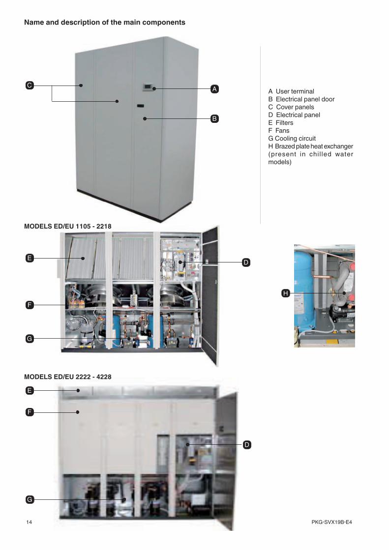
Name and description of the main components
A User terminalB Electrical panel doorC Cover panelsD Electrical panelE FiltersF FansG Cooling circuitH Brazed plate heat exchanger (present in chi l led water models)
MODELS ED/EU 1105 - 2218
MODELS ED/EU 2222 - 4228
B
15PKG-SVX19B-E4
D5
D1
D2
D3
D6
D7a
D4
D8
D7bD7c
D7d
FE
F1
D2 D1
D7a D7c D7bD7d
D3D4 D9
D5 D6D8
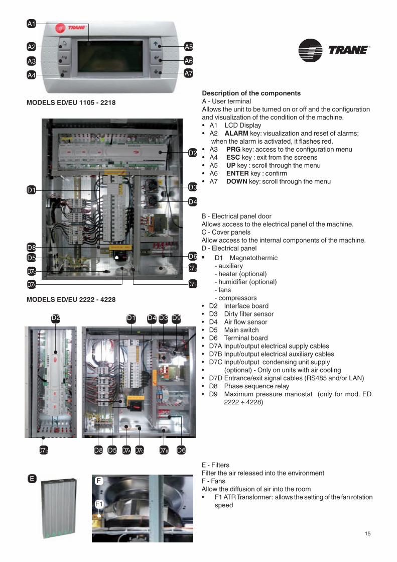
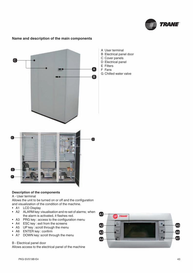
Description of the componentsA - User terminalAllows the unit to be turned on or off and the configuration and visualization of the condition of the machine.• A1 LCD Display• A2 ALARM key: visualization and reset of alarms; when the alarm is activated, it flashes red.• A3 PRG key: access to the configuration menu • A4 ESC key : exit from the screens• A5 UP key : scroll through the menu • A6 ENTER key : confirm• A7 DOWN key: scroll through the menu
B - Electrical panel doorAllows access to the electrical panel of the machine.C - Cover panelsAllow access to the internal components of the machine.D - Electrical panel• D1 Magnetothermic - auxiliary - heater (optional) - humidifier (optional) - fans - compressors• D2 Interface board• D3 Dirty filter sensor• D4 Air flow sensor• D5 Main switch• D6 Terminal board• D7A Input/output electrical supply cables• D7B Input/output electrical auxiliary cables• D7C Input/output condensing unit supply• (optional) - Only on units with air cooling • D7D Entrance/exit signal cables (RS485 and/or LAN)• D8 Phase sequence relay• D9 Maximum pressure manostat (only for mod. ED.
2222 ÷ 4228)
MODELS ED/EU 1105 - 2218
MODELS ED/EU 2222 - 4228
E - FiltersFilter the air released into the environmentF - FansAllow the diffusion of air into the room• F1 ATR Transformer: allows the setting of the fan rotation
speed
A5
A6
A7
A2
A3
A4
A1
PKG-SVX19B-E416
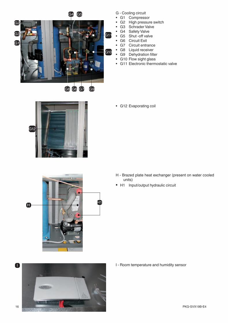
G - Cooling circuit• G1 Compressor• G2 High pressure switch• G3 Schrader Valve• G4 Safety Valve• G5 Shut -off valve• G6 Circuit Exit• G7 Circuit entrance• G8 Liquid receiver• G9 Dehydration filter• G10 Flow sight glass• G11 Electronic thermostatic valve
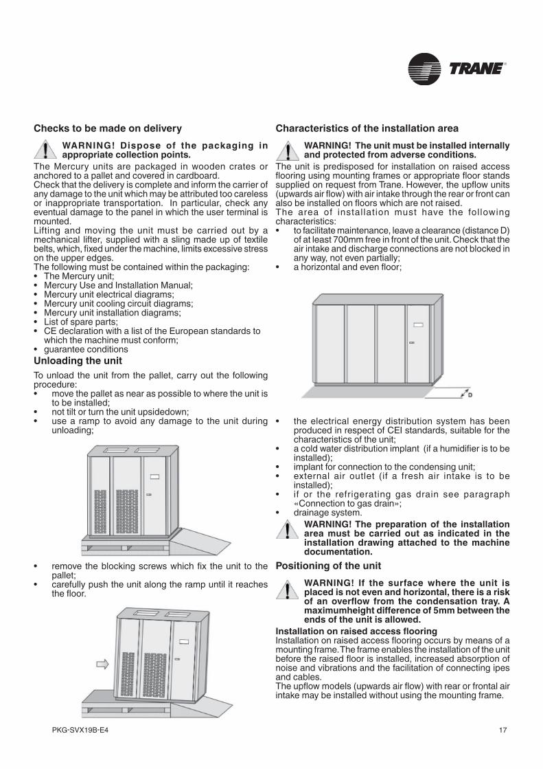
• G12 Evaporating coil
H - Brazed plate heat exchanger (present on water cooled units)
• H1 Input/output hydraulic circuit
I - Room temperature and humidity sensor
H H1
G1
G3
G4 G5
G6 G7G8
G10
G11
G9
G12
I
G2
17PKG-SVX19B-E4
Checks to be made on deliveryWARNING! Dispose of the packaging in appropriate collection points.
The Mercury units are packaged in wooden crates or anchored to a pallet and covered in cardboard.Check that the delivery is complete and inform the carrier of any damage to the unit which may be attributed too careless or inappropriate transportation. In particular, check any eventual damage to the panel in which the user terminal is mounted.Lifting and moving the unit must be carried out by a mechanical lifter, supplied with a sling made up of textile belts, which, fixed under the machine, limits excessive stress on the upper edges. The following must be contained within the packaging:• The Mercury unit;• Mercury Use and Installation Manual;• Mercury unit electrical diagrams;• Mercury unit cooling circuit diagrams;• Mercury unit installation diagrams;• List of spare parts;• CE declaration with a list of the European standards to which the machine must conform;• guarantee conditionsUnloading the unitTo unload the unit from the pallet, carry out the following procedure:• move the pallet as near as possible to where the unit is
to be installed;• not tilt or turn the unit upsidedown;• use a ramp to avoid any damage to the unit during
unloading;
• remove the blocking screws which fix the unit to the pallet;
• carefully push the unit along the ramp until it reaches the floor.
Characteristics of the installation areaWARNING! The unit must be installed internally and protected from adverse conditions.
The unit is predisposed for installation on raised access flooring using mounting frames or appropriate floor stands supplied on request from Trane. However, the upflow units (upwards air flow) with air intake through the rear or front can also be installed on floors which are not raised.The area of instal lat ion must have the fol lowing characteristics:• to facilitate maintenance, leave a clearance (distance D)
of at least 700mm free in front of the unit. Check that the air intake and discharge connections are not blocked in any way, not even partially;
• a horizontal and even floor;
• the electrical energy distribution system has been produced in respect of CEI standards, suitable for the characteristics of the unit;
• a cold water distribution implant (if a humidifier is to be installed);
• implant for connection to the condensing unit;• external air outlet (if a fresh air intake is to be
installed);• if or the refrigerating gas drain see paragraph
«Connection to gas drain»;• drainage system.
WARNING! The preparation of the installation area must be carried out as indicated in the installation drawing attached to the machine documentation.
Positioning of the unitWARNING! If the surface where the unit is placed is not even and horizontal, there is a risk of an overflow from the condensation tray. A maximumheight difference of 5mm between the ends of the unit is allowed.
Installation on raised access flooringInstallation on raised access flooring occurs by means of a mounting frame. The frame enables the installation of the unit before the raised floor is installed, increased absorption of noise and vibrations and the facilitation of connecting ipes and cables.The upflow models (upwards air flow) with rear or frontal air intake may be installed without using the mounting frame.
PKG-SVX19B-E418
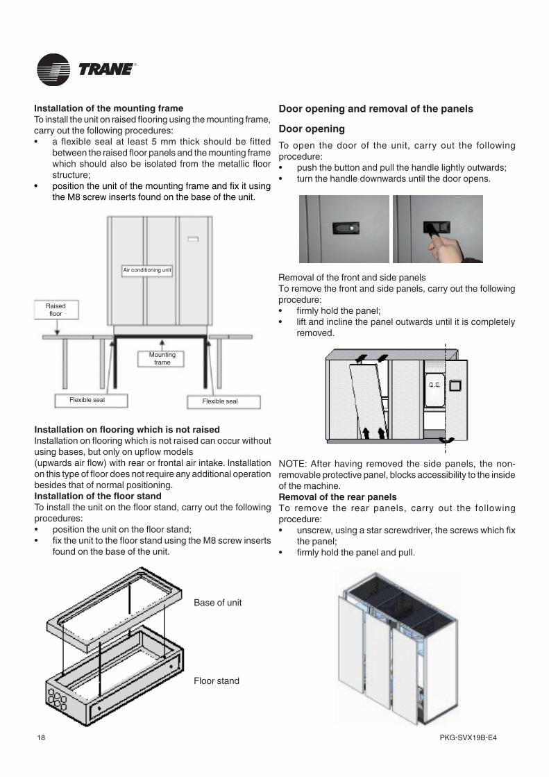
Installation of the mounting frameTo install the unit on raised flooring using the mounting frame, carry out the following procedures:• a flexible seal at least 5 mm thick should be fitted
between the raised floor panels and the mounting frame which should also be isolated from the metallic floor structure;
• position the unit of the mounting frame and fix it using the M8 screw inserts found on the base of the unit.
Installation on flooring which is not raisedInstallation on flooring which is not raised can occur without using bases, but only on upflow models(upwards air flow) with rear or frontal air intake. Installation on this type of floor does not require any additional operation besides that of normal positioning.Installation of the floor standTo install the unit on the floor stand, carry out the following procedures:• position the unit on the floor stand;• fix the unit to the floor stand using the M8 screw inserts
found on the base of the unit.
Door opening and removal of the panels
Door openingTo open the door of the unit, carry out the following procedure:• push the button and pull the handle lightly outwards;• turn the handle downwards until the door opens.
Removal of the front and side panelsTo remove the front and side panels, carry out the following procedure:• firmly hold the panel;• lift and incline the panel outwards until it is completely
removed.
NOTE: After having removed the side panels, the non-removable protective panel, blocks accessibility to the inside of the machine.Removal of the rear panelsTo remove the rear panels, carry out the following procedure:• unscrew, using a star screwdriver, the screws which fix
the panel;• firmly hold the panel and pull.
Base of unit
Floor stand
Air conditioning unit
Raisedfloor
Flexible seal Flexible seal
Mountingframe
19PKG-SVX19B-E4
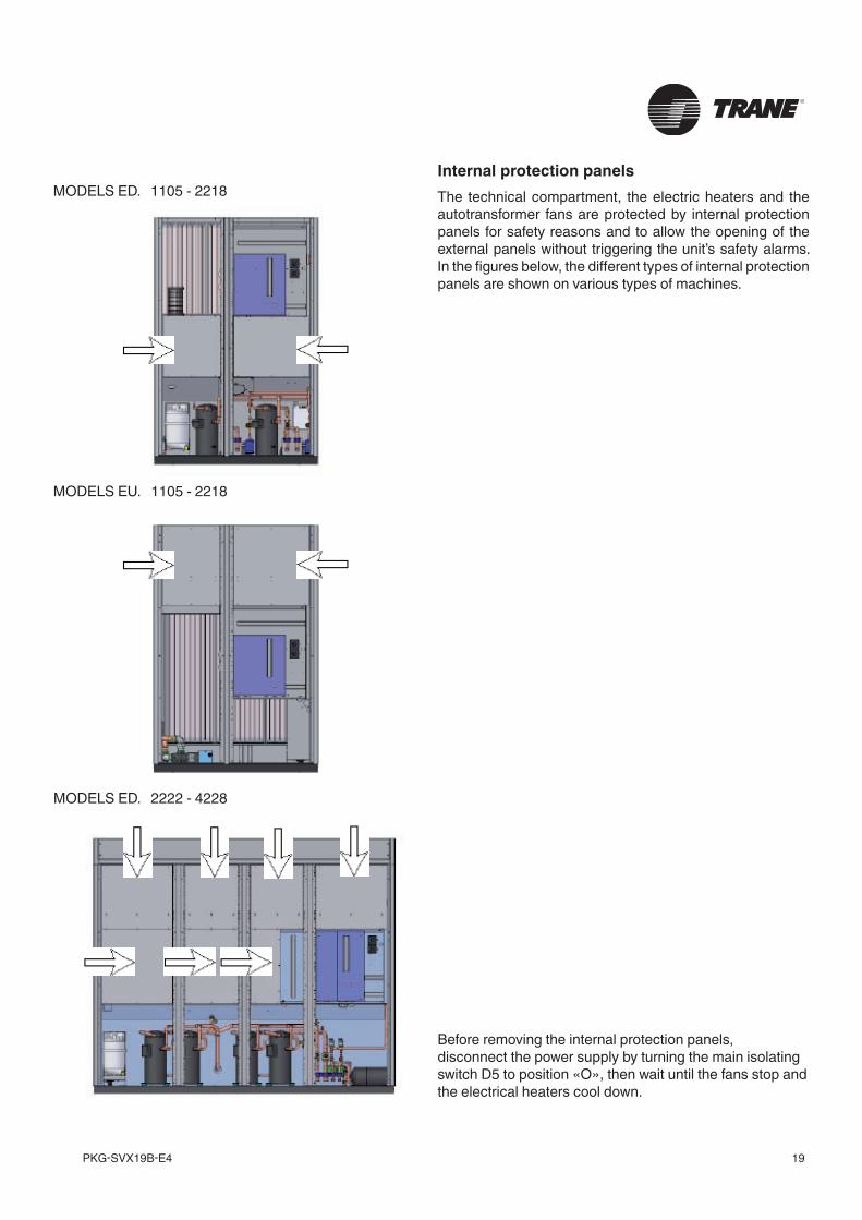
Internal protection panelsThe technical compartment, the electric heaters and the autotransformer fans are protected by internal protection panels for safety reasons and to allow the opening of the external panels without triggering the unit’s safety alarms. In the figures below, the different types of internal protection panels are shown on various types of machines.
Before removing the internal protection panels, disconnect the power supply by turning the main isolating switch D5 to position «O», then wait until the fans stop and the electrical heaters cool down.
MODELS ED. 1105 - 2218
MODELS EU. 1105 - 2218
MODELS ED. 2222 - 4228
PKG-SVX19B-E420
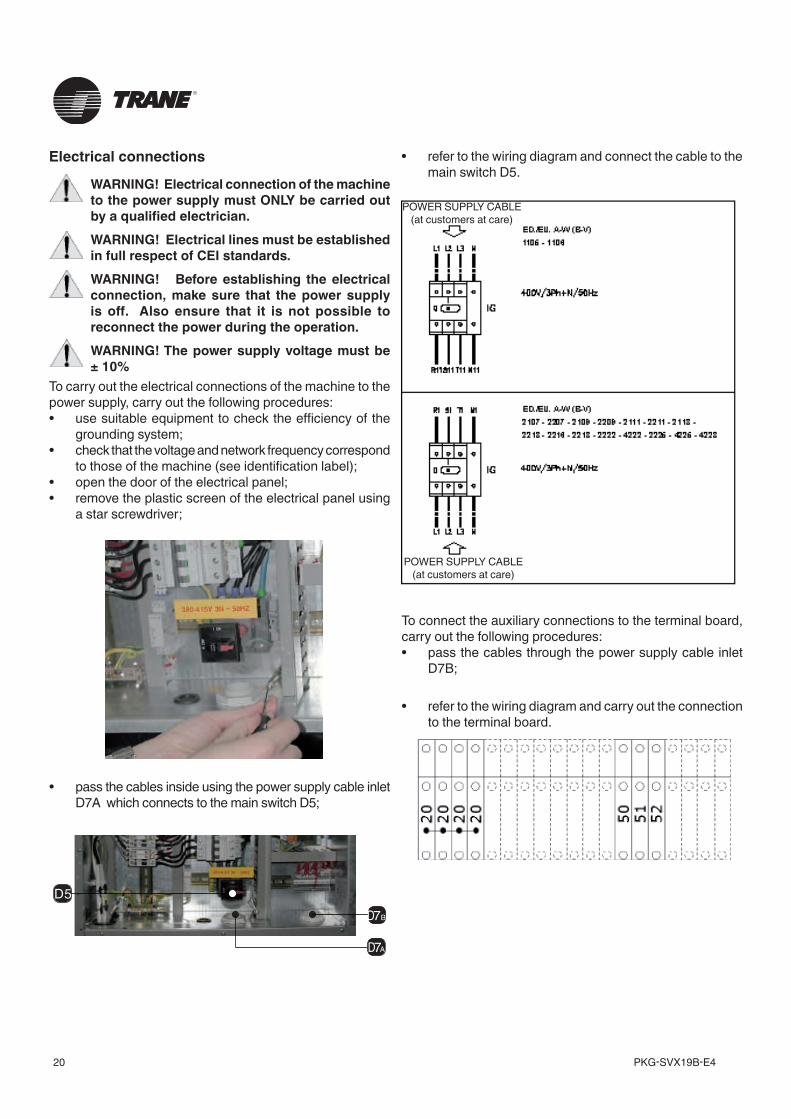
To connect the auxiliary connections to the terminal board, carry out the following procedures:• pass the cables through the power supply cable inlet
D7B;
• refer to the wiring diagram and carry out the connection to the terminal board.
Electrical connections
WARNING! Electrical connection of the machine to the power supply must ONLY be carried out by a qualified electrician.WARNING! Electrical lines must be established in full respect of CEI standards.WARNING! Before establishing the electrical connection, make sure that the power supply is off. Also ensure that it is not possible to reconnect the power during the operation.WARNING! The power supply voltage must be ± 10%
To carry out the electrical connections of the machine to the power supply, carry out the following procedures:• use suitable equipment to check the efficiency of the
grounding system;• check that the voltage and network frequency correspond
to those of the machine (see identification label);• open the door of the electrical panel;• remove the plastic screen of the electrical panel using
a star screwdriver;
D5
D7a
D7b
• pass the cables inside using the power supply cable inlet D7A which connects to the main switch D5;
• refer to the wiring diagram and connect the cable to the main switch D5.
POWER SUPPLY CABLE (at customers at care)
POWER SUPPLY CABLE (at customers at care)
21PKG-SVX19B-E4
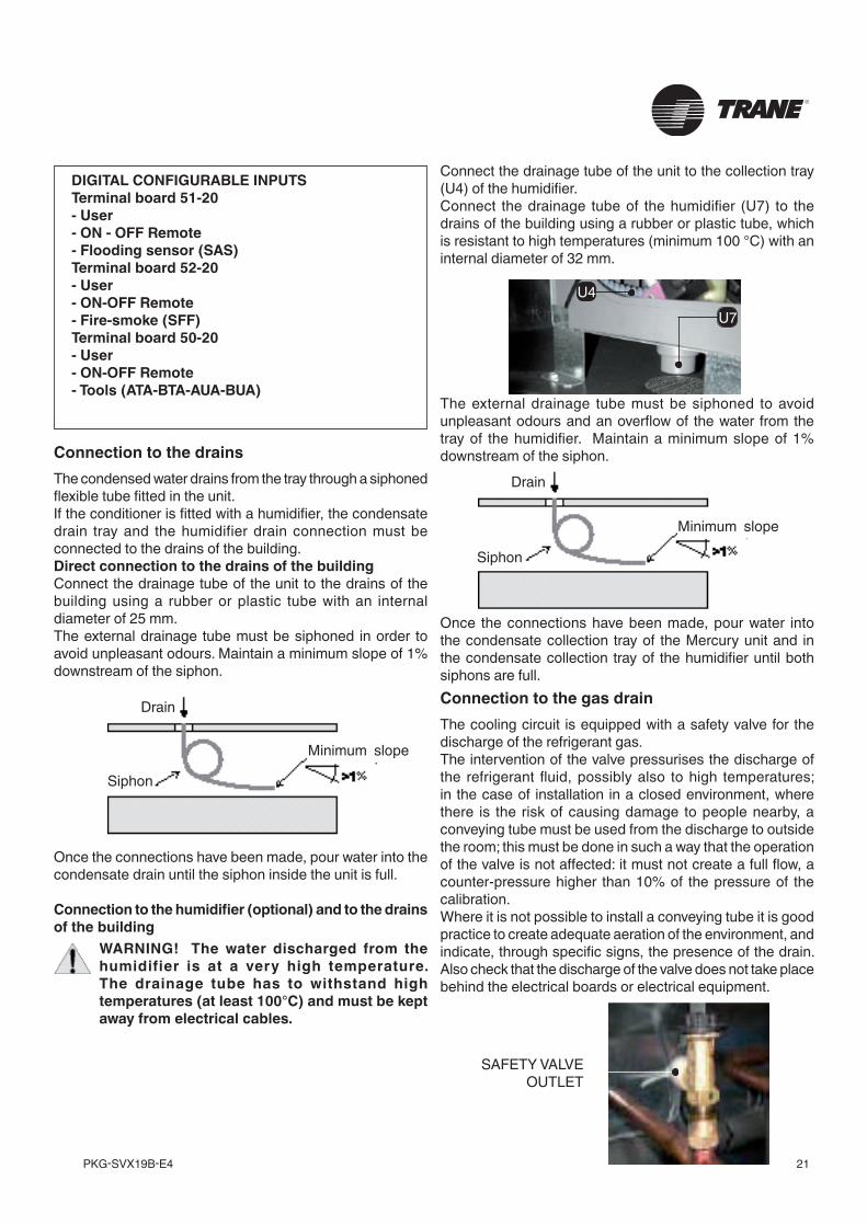
Connection to the drainsThe condensed water drains from the tray through a siphoned flexible tube fitted in the unit.If the conditioner is fitted with a humidifier, the condensate drain tray and the humidifier drain connection must be connected to the drains of the building.Direct connection to the drains of the building Connect the drainage tube of the unit to the drains of the building using a rubber or plastic tube with an internal diameter of 25 mm.The external drainage tube must be siphoned in order to avoid unpleasant odours. Maintain a minimum slope of 1% downstream of the siphon.
Once the connections have been made, pour water into the condensate drain until the siphon inside the unit is full.
Connection to the humidifier (optional) and to the drains of the building
WARNING! The water discharged from the humidifier is at a very high temperature. The drainage tube has to withstand high temperatures (at least 100°C) and must be kept away from electrical cables.
The external drainage tube must be siphoned to avoid unpleasant odours and an overflow of the water from the tray of the humidifier. Maintain a minimum slope of 1% downstream of the siphon.
Once the connections have been made, pour water into the condensate collection tray of the Mercury unit and in the condensate collection tray of the humidifier until both siphons are full.Connection to the gas drainThe cooling circuit is equipped with a safety valve for the discharge of the refrigerant gas.The intervention of the valve pressurises the discharge of the refrigerant fluid, possibly also to high temperatures; in the case of installation in a closed environment, where there is the risk of causing damage to people nearby, a conveying tube must be used from the discharge to outside the room; this must be done in such a way that the operation of the valve is not affected: it must not create a full flow, a counter-pressure higher than 10% of the pressure of the calibration.Where it is not possible to install a conveying tube it is good practice to create adequate aeration of the environment, and indicate, through specific signs, the presence of the drain. Also check that the discharge of the valve does not take place behind the electrical boards or electrical equipment.
U7U4
SAFETY VALVE OUTLET
Connect the drainage tube of the unit to the collection tray (U4) of the humidifier.Connect the drainage tube of the humidifier (U7) to the drains of the building using a rubber or plastic tube, which is resistant to high temperatures (minimum 100 °C) with an internal diameter of 32 mm.
DIGITAL CONFIGURABLE INPUTSTerminal board 51-20- User- ON - OFF Remote- Flooding sensor (SAS)Terminal board 52-20- User- ON-OFF Remote- Fire-smoke (SFF)Terminal board 50-20- User- ON-OFF Remote- Tools (ATA-BTA-AUA-BUA)
Minimum slope
Minimum slope
Drain
Drain
Siphon
Siphon
PKG-SVX19B-E422
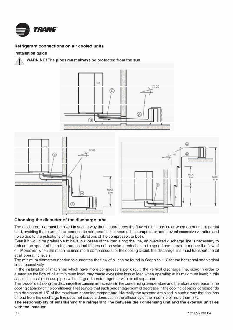
Refrigerant connections on air cooled unitsInstallation guide
WARNING! The pipes must always be protected from the sun.
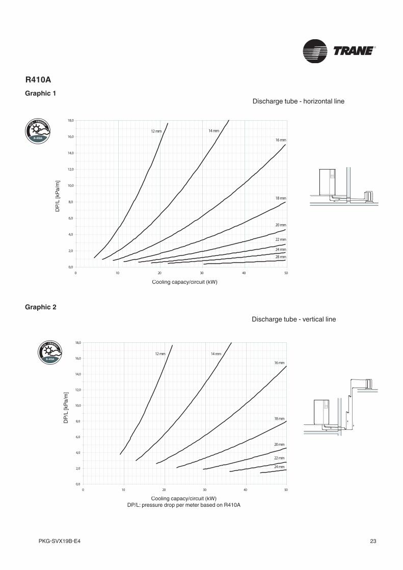
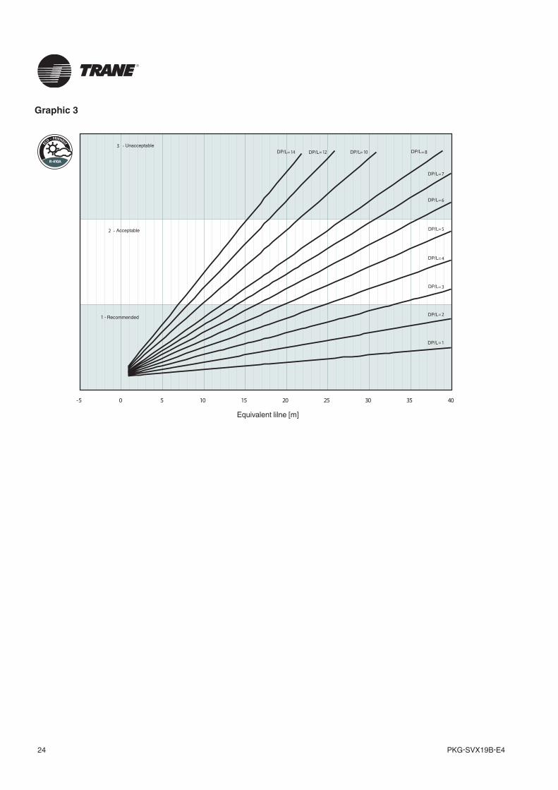
Choosing the diameter of the discharge tubeThe discharge line must be sized in such a way that it guarantees the flow of oil, in particular when operating at partial load, avoiding the return of the condensate refrigerant to the head of the compressor and prevent excessive vibration and noise due to the pulsations of hot gas, vibrations of the compressor, or both.Even if it would be preferable to have low losses of the load along the line, an oversized discharge line is necessary to reduce the speed of the refrigerant so that it does not provoke a reduction in its speed and therefore reduce the flow of oil. Moreover, when the machine uses more compressors for the cooling circuit, the discharge line must transport the oil at all operating levels.The minimum diameters needed to guarantee the flow of oil can be found in Graphics 1 -2 for the horizontal and vertical lines respectively.In the installation of machines which have more compressors per circuit, the vertical discharge line, sized in order to guarantee the flow of oil at minimum load, may cause excessive loss of load when operating at its maximum level; in this case it is possible to use pipes with a larger diameter together with an oil separator.The loss of load along the discharge line causes an increase in the condensing temperature and therefore a decrease in the cooling capacity of the conditioner. Please note that each percentage point of decrease in the cooling capacity corresponds to a decrease of 1°C of the maximum operating temperature. Normally the systems are sized in such a way that the loss of load from the discharge line does not cause a decrease in the efficiency of the machine of more than -3%. The responsibility of establishing the refrigerant line between the condensing unit and the external unit lies with the installer.
23PKG-SVX19B-E4
0 10 20 30 40 50
0,0
2,0
4,0
6,0
8,0
10,0
12,0
14,0
16,0
18,0
DP/L
[kPa
/m]
12 mm 14 mm
16 mm
18 mm
20 mm
22 mm
24 mm
R410AGraphic 1
Discharge tube - horizontal line
DP/L
[kPa
/m]
0,0
2,0
4,0
6,0
8,0
10,0
12,0
14,0
16,0
18,0
0 10 20 30 40 50
12 mm 14 mm
16 mm
18 mm
20 mm
22 mm
24 mm
28 mm
Cooling capacy/circuit (kW)
DP/
L [k
Pa/m
]D
P/L
[kPa
/m]
Cooling capacy/circuit (kW)DP/L: pressure drop per meter based on R410A
Discharge tube - vertical line
Graphic 2
PKG-SVX19B-E424
Graphic 3
-5 0 5 10 15 20 25 30 35 40
Equivalent line [m]
3 -
2 -
1 -
= 14 = 12 = 10 = 8
= 7
= 6
= 5
= 4
= 3
= 2
= 1
Equivalent lilne [m]
Unacceptable
Acceptable
Recommended
DP/L DP/L DP/L DP/L
DP/L
DP/L
DP/L
DP/L
DP/L
DP/L
DP/L
25PKG-SVX19B-E4
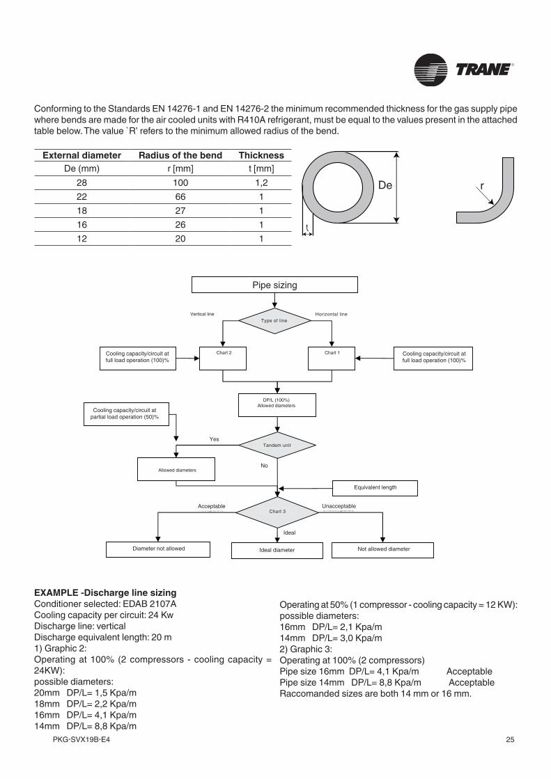
Conforming to the Standards EN 14276-1 and EN 14276-2 the minimum recommended thickness for the gas supply pipe where bends are made for the air cooled units with R410A refrigerant, must be equal to the values present in the attached table below. The value `R’ refers to the minimum allowed radius of the bend.
External diameter Radius of the bend ThicknessDe (mm) r [mm] t [mm]
28 100 1,222 66 118 27 116 26 112 20 1
EXAMPLE -Discharge line sizingConditioner selected: EDAB 2107A Cooling capacity per circuit: 24 Kw Discharge line: verticalDischarge equivalent length: 20 m1) Graphic 2:Operating at 100% (2 compressors - cooling capacity = 24KW): possible diameters:20mm DP/L= 1,5 Kpa/m18mm DP/L= 2,2 Kpa/m16mm DP/L= 4,1 Kpa/m14mm DP/L= 8,8 Kpa/m
Operating at 50% (1 compressor - cooling capacity = 12 KW): possible diameters:16mm DP/L= 2,1 Kpa/m14mm DP/L= 3,0 Kpa/m2) Graphic 3:Operating at 100% (2 compressors) Pipe size 16mm DP/L= 4,1 Kpa/m AcceptablePipe size 14mm DP/L= 8,8 Kpa/m AcceptableRaccomanded sizes are both 14 mm or 16 mm.
Cooling capacity/circuit atpartial load operation (50)%
Cooling capacity/circuit atfull load operation (100)%
E quivalent length
No
Chart 3
P ipe s izing
Type of line
Chart 2
Vertical line
Chart1
Horizontal line
Cooling capacity/circuit atfull load operation (100)%
DP/L (100%)Allowed diameters
Tandem unit
Allowed diameters
Not allowed diameterIdeal diameterAllowed diameter but no recomended
Acceptable
Ideal
Unacceptable
Yes
Pipe sizing
Vertical line
Chart 2 Chart 1
DP/L (100%) Allowed diameters
Cooling capacity/circuit at full load operation (100)%
Cooling capacity/circuit at full load operation (100)%
Cooling capacity/circuit at partial load operation (50)%
Allowed diameters
Equivalent length
Not allowed diameterIdeal diameterDiameter not allowed
Acceptable Unacceptable
No
Ideal
Yes
Horizontal lineType of line
Tandem unit
Chart 3
De r
t
De r
t
PKG-SVX19B-E426
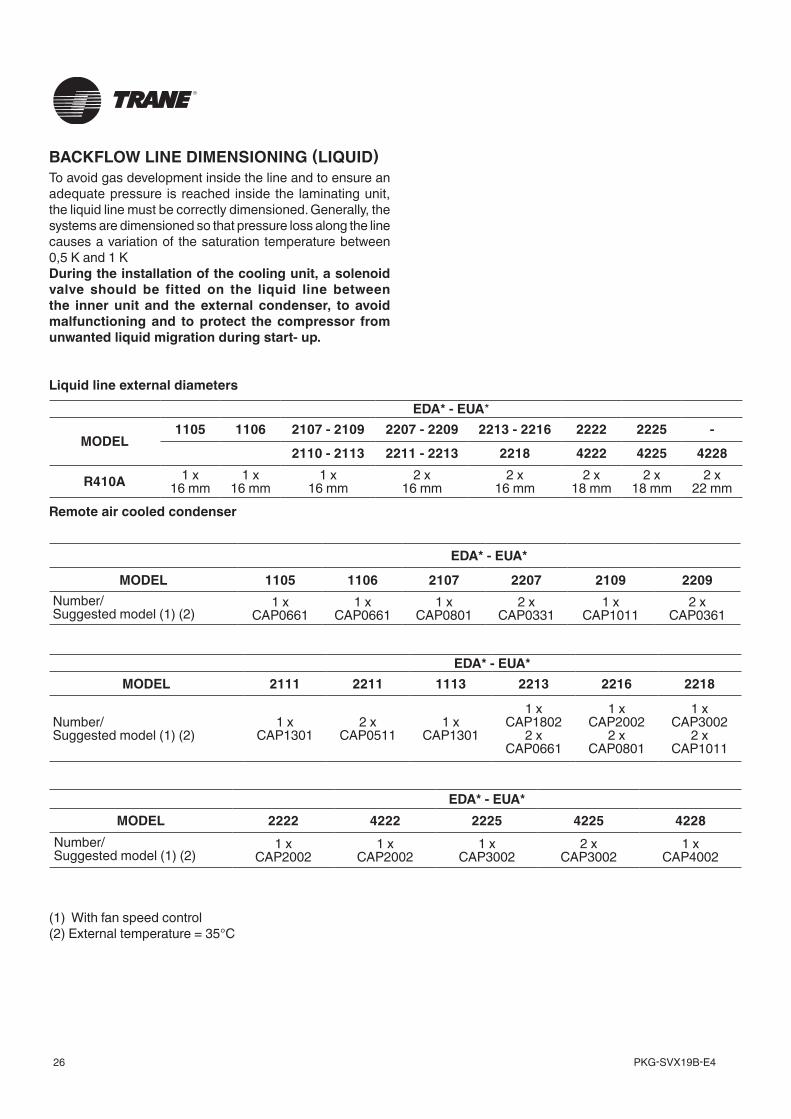
BACKFLOW LINE DIMENSIONING (LIQUID)To avoid gas development inside the line and to ensure an adequate pressure is reached inside the laminating unit, the liquid line must be correctly dimensioned. Generally, the systems are dimensioned so that pressure loss along the line causes a variation of the saturation temperature between 0,5 K and 1 KDuring the installation of the cooling unit, a solenoid valve should be fitted on the liquid line between the inner unit and the external condenser, to avoid malfunctioning and to protect the compressor from unwanted liquid migration during start- up.
Liquid line external diameters
Remote air cooled condenser
EDA* - EUA*
MODEL 1105 1106 2107 2207 2109 2209Number/Suggested model (1) (2)
1 xCAP0661
1 xCAP0661
1 xCAP0801
2 xCAP0331
1 xCAP1011
2 xCAP0361
EDA* - EUA* MODEL 2111 2211 1113 2213 2216 2218
Number/Suggested model (1) (2)
1 xCAP1301
2 xCAP0511
1 xCAP1301
1 xCAP1802
2 xCAP0661
1 xCAP2002
2 xCAP0801
1 xCAP3002
2 xCAP1011
EDA* - EUA*
MODEL1105 1106 2107 - 2109 2207 - 2209 2213 - 2216 2222 2225 -
2110 - 2113 2211 - 2213 2218 4222 4225 4228
R410A 1 x16 mm
1 x16 mm
1 x16 mm
2 x16 mm
2 x16 mm
2 x18 mm
2 x18 mm
2 x22 mm
EDA* - EUA* MODEL 2222 4222 2225 4225 4228
Number/Suggested model (1) (2)
1 xCAP2002
1 xCAP2002
1 xCAP3002
2 xCAP3002
1 xCAP4002
(1) With fan speed control(2) External temperature = 35°C
27PKG-SVX19B-E4
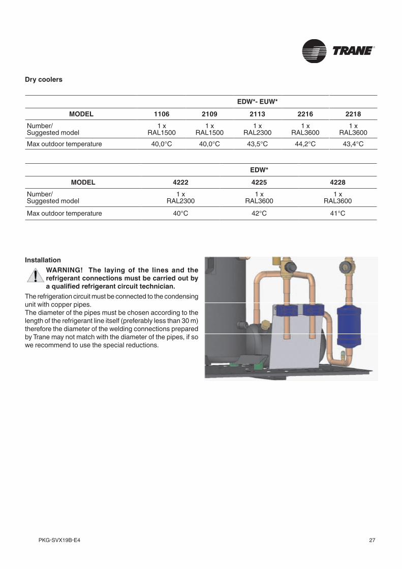
InstallationWARNING! The laying of the lines and the refrigerant connections must be carried out by a qualified refrigerant circuit technician.
The refrigeration circuit must be connected to the condensing unit with copper pipes.The diameter of the pipes must be chosen according to the length of the refrigerant line itself (preferably less than 30 m) therefore the diameter of the welding connections prepared by Trane may not match with the diameter of the pipes, if so we recommend to use the special reductions.
Dry coolers
EDW*- EUW*
MODEL 1106 2109 2113 2216 2218Number/Suggested model
1 xRAL1500
1 xRAL1500
1 xRAL2300
1 xRAL3600
1 xRAL3600
Max outdoor temperature 40,0°C 40,0°C 43,5°C 44,2°C 43,4°C
EDW*
MODEL 4222 4225 4228Number/Suggested model
1 xRAL2300
1 xRAL3600
1 xRAL3600
Max outdoor temperature 40°C 42°C 41°C
PKG-SVX19B-E428
Evacuation of the refrigeration circuit and charging of refrigerantWARNING! The charging and maintenance of the refrigeration circuit must only be carried out by a qualified hydraulic technician.
The refrigeration circuit is pre-charged with nitrogen.To load the refrigerant, carry out the following procedure:
R410A• open any shut-off valves present in the machine to
ensure that all of the components will be evacuated;• connect a pump to empty the schrader connections
efficiently, or to the 1/4» SAE connections present on the intake and delivery sides of the compressors;
• connect the refrigerant cylinder to the loading connections;
• create a vacuum within the lines whilst maintaining the pressure below 10 Pa absolute (0,07 mm Hg) for a long time in order to evacuate the air as well as any trace of humidity. It is preferable that the vacuum is reached slowly and maintained for a long period of time;
• wait for a build up period of 100 seconds and check that the pressure has not exceeded 200 Pa absolute. Generally, in the case of suspicion of strong hydration of the circuit or an extremely extensive system, it will be necessary to break the vacuum with anhydrous nitrogen and then repeat the evacuation procedure as described;
• break the vacuum by performing a preload in liquid phase from the R410A coolant cylinder;
• after having started the compressor, slowly complete the loading phase until the pressure within the lines has been stabilised and the gaseous bubbles have disappeared from the flow sight glass;
• the loading process must be controlled in environmental conditions with a delivery pressure of approximately 18 bar (equivalent to a dew temperature of 48 °C and a bubble temperature of 43 °C); in the case of units with ON/OFF condensation controls, avoid switching the condenser fan on and off, which may partially obstruct the intake surface. It is wise to check that the sub-cooling of the liquid at the entry of the thermostatic valve is between 3 and 5 °C below the condensation temperature read on the scale of the pressure gauge and that the overheating of the vapour at the exit of the evaporator is equal to approximately 5-8 °C.
Type of oil recommended with MANEUROP compressors
Type of oil recommended with SANYO compressors
Type of oil recommended with Scrolltech HRH-HLH-HLJ-HCJ compressors
R410A (PVE) PVE FVC68D
R410A (POE) Maneurop 160 SZ
R410A (PVE) FV68S
29PKG-SVX19B-E4
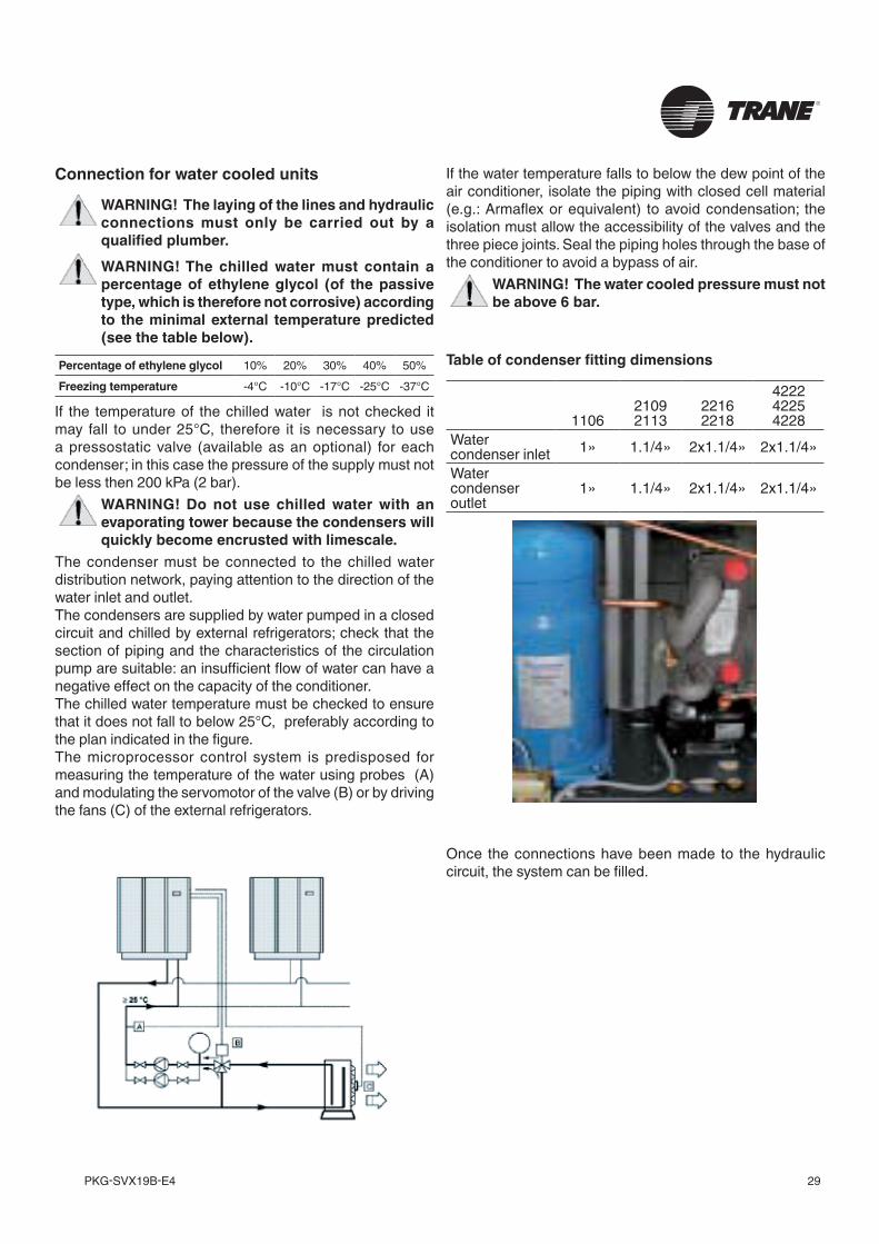
Connection for water cooled units
WARNING! The laying of the lines and hydraulic connections must only be carried out by a qualified plumber.WARNING! The chilled water must contain a percentage of ethylene glycol (of the passive type, which is therefore not corrosive) according to the minimal external temperature predicted (see the table below).
If the water temperature falls to below the dew point of the air conditioner, isolate the piping with closed cell material (e.g.: Armaflex or equivalent) to avoid condensation; the isolation must allow the accessibility of the valves and the three piece joints. Seal the piping holes through the base of the conditioner to avoid a bypass of air.
WARNING! The water cooled pressure must not be above 6 bar.
Percentage of ethylene glycol 10% 20% 30% 40% 50%Freezing temperature -4°C -10°C -17°C -25°C -37°C
If the temperature of the chilled water is not checked it may fall to under 25°C, therefore it is necessary to use a pressostatic valve (available as an optional) for each condenser; in this case the pressure of the supply must not be less then 200 kPa (2 bar).
WARNING! Do not use chilled water with an evaporating tower because the condensers will quickly become encrusted with limescale.
The condenser must be connected to the chilled water distribution network, paying attention to the direction of the water inlet and outlet.The condensers are supplied by water pumped in a closed circuit and chilled by external refrigerators; check that the section of piping and the characteristics of the circulation pump are suitable: an insufficient flow of water can have a negative effect on the capacity of the conditioner.The chilled water temperature must be checked to ensure that it does not fall to below 25°C, preferably according to the plan indicated in the figure.The microprocessor control system is predisposed for measuring the temperature of the water using probes (A) and modulating the servomotor of the valve (B) or by driving the fans (C) of the external refrigerators.
110621092113
22162218
422242254228
Water condenser inlet 1» 1.1/4» 2x1.1/4» 2x1.1/4»Water condenser outlet
1» 1.1/4» 2x1.1/4» 2x1.1/4»
Table of condenser fitting dimensions
Once the connections have been made to the hydraulic circuit, the system can be filled.
PKG-SVX19B-E430
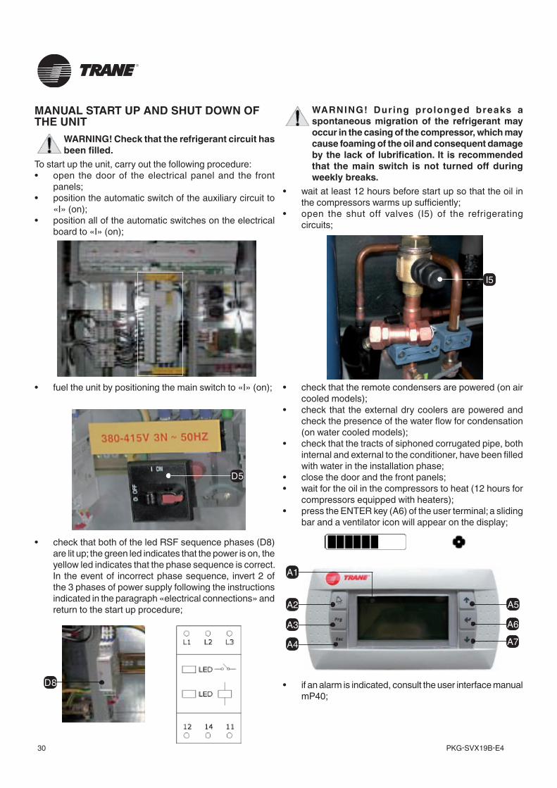
MANUAL START UP AND SHUT DOWN OF THE UNIT
WARNING! Check that the refrigerant circuit has been filled.
To start up the unit, carry out the following procedure:• open the door of the electrical panel and the front
panels;• position the automatic switch of the auxiliary circuit to
«I» (on);• position all of the automatic switches on the electrical
board to «I» (on);
• fuel the unit by positioning the main switch to «I» (on);
• check that both of the led RSF sequence phases (D8) are lit up; the green led indicates that the power is on, the yellow led indicates that the phase sequence is correct. In the event of incorrect phase sequence, invert 2 of the 3 phases of power supply following the instructions indicated in the paragraph «electrical connections» and return to the start up procedure;
D8
WARNING! During prolonged breaks a spontaneous migration of the refrigerant may occur in the casing of the compressor, which may cause foaming of the oil and consequent damage by the lack of lubrification. It is recommended that the main switch is not turned off during weekly breaks.
• wait at least 12 hours before start up so that the oil in the compressors warms up sufficiently;
• open the shut off valves (I5) of the refrigerating circuits;
• check that the remote condensers are powered (on air cooled models);
• check that the external dry coolers are powered and check the presence of the water flow for condensation (on water cooled models);
• check that the tracts of siphoned corrugated pipe, both internal and external to the conditioner, have been filled with water in the installation phase;
• close the door and the front panels;• wait for the oil in the compressors to heat (12 hours for
compressors equipped with heaters);• press the ENTER key (A6) of the user terminal; a sliding
bar and a ventilator icon will appear on the display;
• if an alarm is indicated, consult the user interface manual mP40;
I5
D5
A5
A6
A7
A2
A3
A4
A1
31PKG-SVX19B-E4
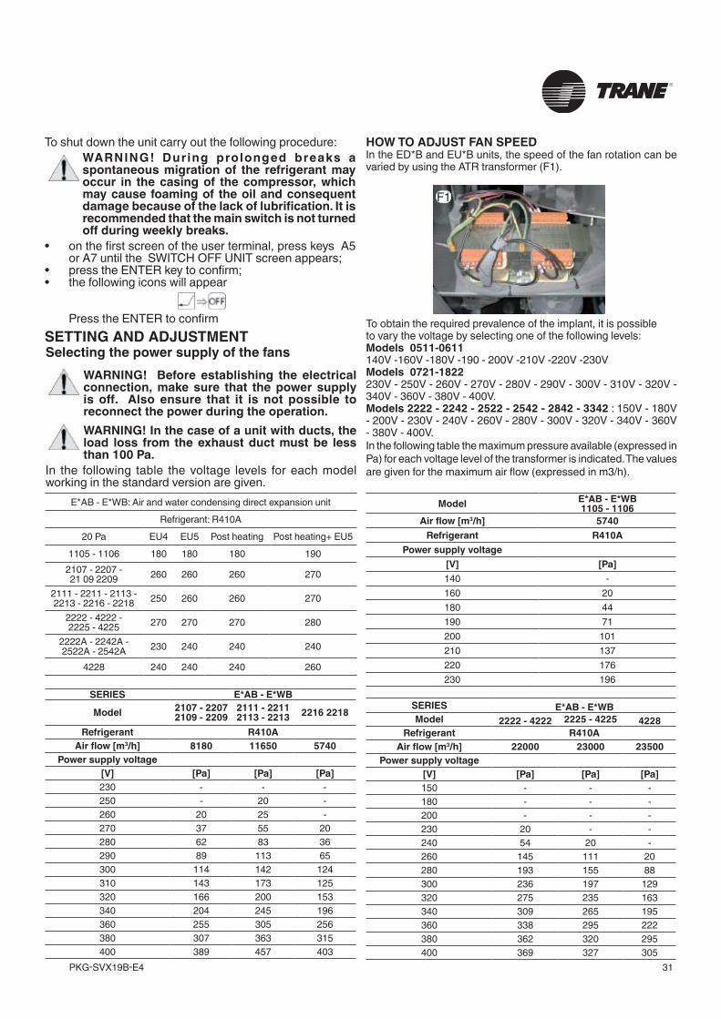
Selecting the power supply of the fansWARNING! Before establishing the electrical connection, make sure that the power supply is off. Also ensure that it is not possible to reconnect the power during the operation.WARNING! In the case of a unit with ducts, the load loss from the exhaust duct must be less than 100 Pa.
In the following table the voltage levels for each model working in the standard version are given.
HOW TO ADJUST FAN SPEEDIn the ED*B and EU*B units, the speed of the fan rotation can be varied by using the ATR transformer (F1).
To shut down the unit carry out the following procedure:WARNING! During prolonged breaks a spontaneous migration of the refrigerant may occur in the casing of the compressor, which may cause foaming of the oil and consequent damage because of the lack of lubrification. It is recommended that the main switch is not turned off during weekly breaks.
• on the first screen of the user terminal, press keys A5 or A7 until the SWITCH OFF UNIT screen appears;
• press the ENTER key to confirm;• the following icons will appear
Press the ENTER to confirmSETTING AND ADJUSTMENT
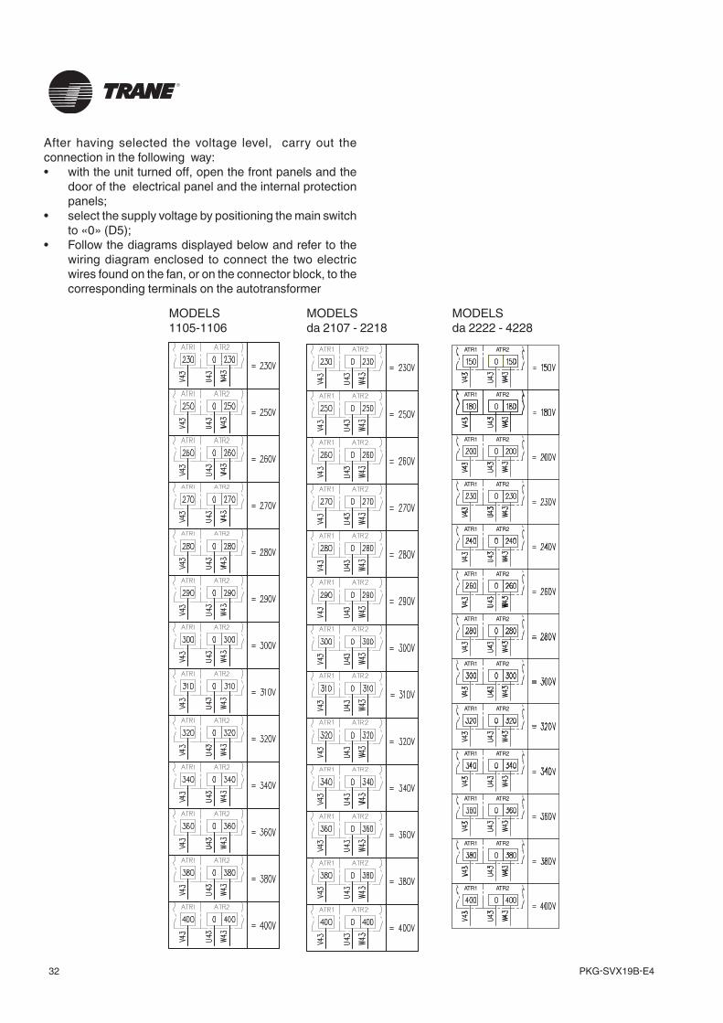
To obtain the required prevalence of the implant, it is possible to vary the voltage by selecting one of the following levels:Models 0511-0611140V -160V -180V -190 - 200V -210V -220V -230VModels 0721-1822230V - 250V - 260V - 270V - 280V - 290V - 300V - 310V - 320V - 340V - 360V - 380V - 400V. Models 2222 - 2242 - 2522 - 2542 - 2842 - 3342 : 150V - 180V - 200V - 230V - 240V - 260V - 280V - 300V - 320V - 340V - 360V - 380V - 400V.In the following table the maximum pressure available (expressed in Pa) for each voltage level of the transformer is indicated. The values are given for the maximum air flow (expressed in m3/h).
F1
E*AB - E*WB: Air and water condensing direct expansion unitRefrigerant: R410A
20 Pa EU4 EU5 Post heating Post heating+ EU51105 - 1106 180 180 180 190
2107 - 2207 - 21 09 2209 260 260 260 270
2111 - 2211 - 2113 - 2213 - 2216 - 2218 250 260 260 270
2222 - 4222 - 2225 - 4225 270 270 270 280
2222A - 2242A - 2522A - 2542A 230 240 240 240
4228 240 240 240 260
Model E*AB - E*WB1105 - 1106
Air flow [m3/h] 5740Refrigerant R410A
Power supply voltage[V] [Pa]140 -160 20180 44190 71200 101210 137220 176230 196
SERIES E*AB - E*WB
Model 2107 - 2207 2109 - 2209
2111 - 2211 2113 - 2213 2216 2218
Refrigerant R410AAir flow [m3/h] 8180 11650 5740
Power supply voltage[V] [Pa] [Pa] [Pa]230 - - -250 - 20 -260 20 25 -270 37 55 20280 62 83 36290 89 113 65300 114 142 124310 143 173 125320 166 200 153340 204 245 196360 255 305 256380 307 363 315400 389 457 403
SERIES E*AB - E*WBModel 2222 - 4222 2225 - 4225 4228
Refrigerant R410AAir flow [m3/h] 22000 23000 23500
Power supply voltage[V] [Pa] [Pa] [Pa]150 - - -180 - - -200 - - -230 20 - -240 54 20 -260 145 111 20280 193 155 88300 236 197 129320 275 235 163340 309 265 195360 338 295 222380 362 320 295400 369 327 305
PKG-SVX19B-E432
After having selected the voltage level, carry out the connection in the following way:• with the unit turned off, open the front panels and the
door of the electrical panel and the internal protection panels;
• select the supply voltage by positioning the main switch to «0» (D5);
• Follow the diagrams displayed below and refer to the wiring diagram enclosed to connect the two electric wires found on the fan, or on the connector block, to the corresponding terminals on the autotransformer
MODELS da 2107 - 2218
MODELS da 2222 - 4228
MODELS 1105-1106
ATR1 ATR2
ATR1 ATR2
ATR1 ATR2
ATR1 ATR2
ATR1 ATR2
ATR1 ATR2
ATR1 ATR2
ATR1 ATR2
ATR1 ATR2
ATR1 ATR2
ATR1 ATR2
ATR1 ATR2
ATR1 ATR2
33PKG-SVX19B-E4
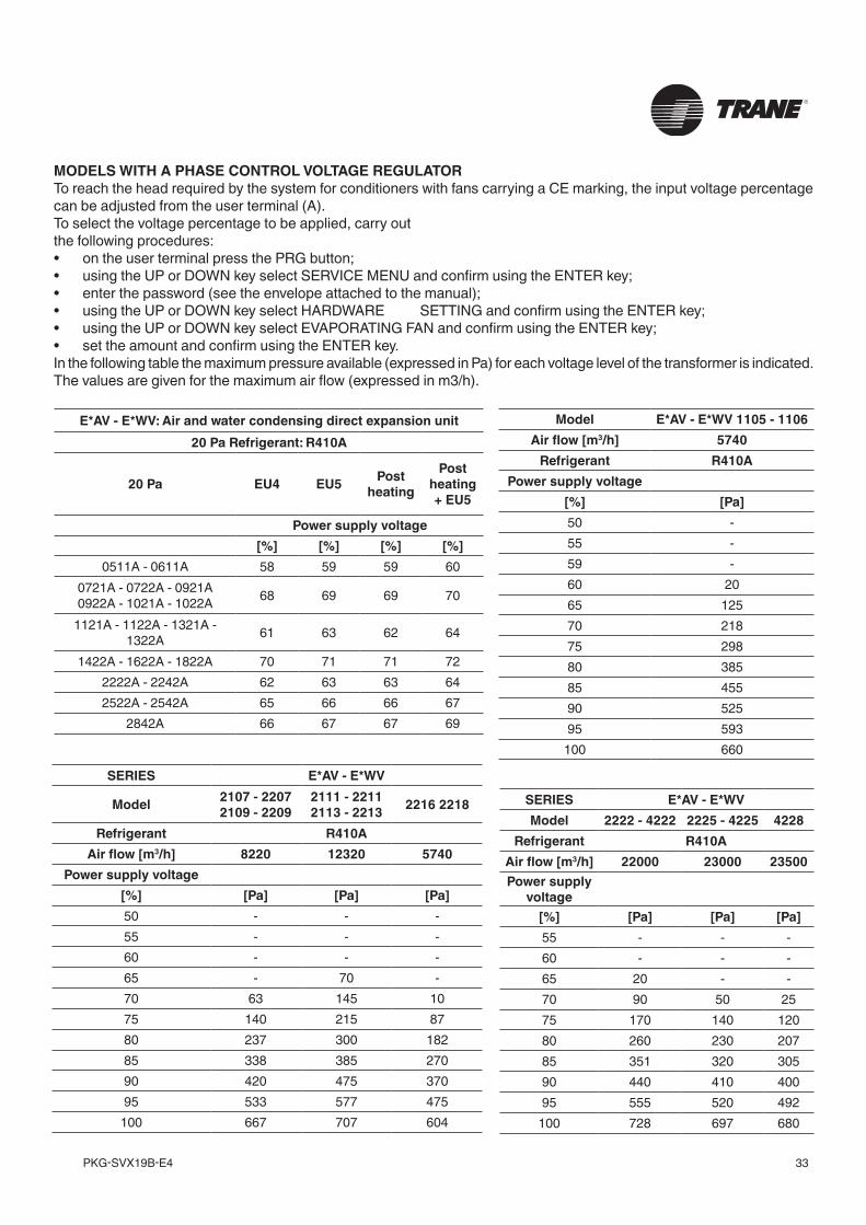
MODELS WITH A PHASE CONTROL VOLTAGE REGULATORTo reach the head required by the system for conditioners with fans carrying a CE marking, the input voltage percentage can be adjusted from the user terminal (A).To select the voltage percentage to be applied, carry out the following procedures:• on the user terminal press the PRG button;• using the UP or DOWN key select SERVICE MENU and confirm using the ENTER key;• enter the password (see the envelope attached to the manual);• using the UP or DOWN key select HARDWARE SETTING and confirm using the ENTER key;• using the UP or DOWN key select EVAPORATING FAN and confirm using the ENTER key;• set the amount and confirm using the ENTER key.In the following table the maximum pressure available (expressed in Pa) for each voltage level of the transformer is indicated. The values are given for the maximum air flow (expressed in m3/h).
E*AV - E*WV: Air and water condensing direct expansion unit20 Pa Refrigerant: R410A
20 Pa EU4 EU5 Post heating
Post heating + EU5
Power supply voltage[%] [%] [%] [%]
0511A - 0611A 58 59 59 600721A - 0722A - 0921A 0922A - 1021A - 1022A 68 69 69 70
1121A - 1122A - 1321A - 1322A 61 63 62 64
1422A - 1622A - 1822A 70 71 71 72 2222A - 2242A 62 63 63 64 2522A - 2542A 65 66 66 67
2842A 66 67 67 69
Model E*AV - E*WV 1105 - 1106 Air flow [m3/h] 5740
Refrigerant R410A Power supply voltage
[%] [Pa] 50 - 55 - 59 - 60 20 65 125 70 218 75 298 80 385 85 455 90 525 95 593
100 660
SERIES E*AV - E*WV
Model 2107 - 2207 2109 - 2209
2111 - 2211 2113 - 2213 2216 2218
Refrigerant R410A Air flow [m3/h] 8220 12320 5740
Power supply voltage [%] [Pa] [Pa] [Pa] 50 - - - 55 - - - 60 - - - 65 - 70 - 70 63 145 10 75 140 215 87 80 237 300 182 85 338 385 270 90 420 475 370 95 533 577 475
100 667 707 604
SERIES E*AV - E*WV Model 2222 - 4222 2225 - 4225 4228
Refrigerant R410A Air flow [m3/h] 22000 23000 23500 Power supply
voltage [%] [Pa] [Pa] [Pa] 55 - - - 60 - - - 65 20 - - 70 90 50 25 75 170 140 120 80 260 230 207 85 351 320 305 90 440 410 400 95 555 520 492
100 728 697 680
PKG-SVX19B-E434
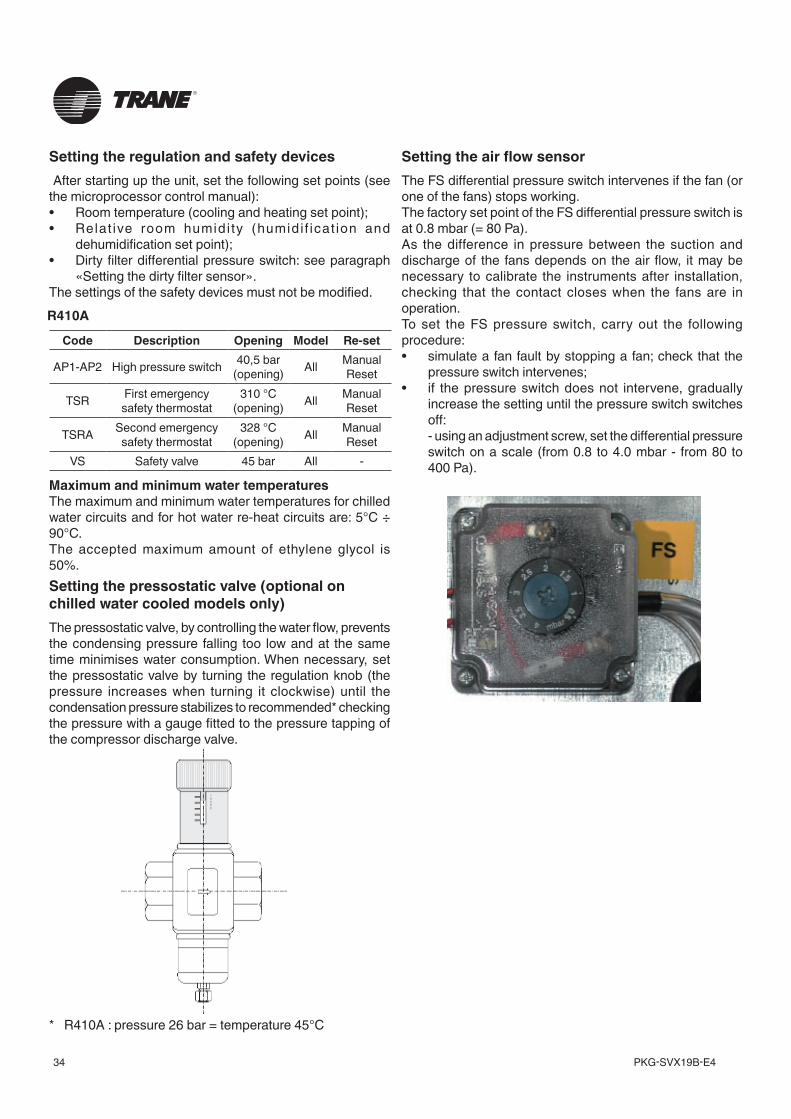
Maximum and minimum water temperaturesThe maximum and minimum water temperatures for chilled water circuits and for hot water re-heat circuits are: 5°C ÷ 90°C.The accepted maximum amount of ethylene glycol is 50%.Setting the pressostatic valve (optional on chilled water cooled models only)The pressostatic valve, by controlling the water flow, prevents the condensing pressure falling too low and at the same time minimises water consumption. When necessary, set the pressostatic valve by turning the regulation knob (the pressure increases when turning it clockwise) until the condensation pressure stabilizes to recommended* checking the pressure with a gauge fitted to the pressure tapping of the compressor discharge valve.
Setting the air flow sensorThe FS differential pressure switch intervenes if the fan (or one of the fans) stops working.The factory set point of the FS differential pressure switch is at 0.8 mbar (= 80 Pa).As the difference in pressure between the suction and discharge of the fans depends on the air flow, it may be necessary to calibrate the instruments after installation, checking that the contact closes when the fans are in operation.To set the FS pressure switch, carry out the following procedure:• simulate a fan fault by stopping a fan; check that the
pressure switch intervenes;• if the pressure switch does not intervene, gradually
increase the setting until the pressure switch switches off:
- using an adjustment screw, set the differential pressure switch on a scale (from 0.8 to 4.0 mbar - from 80 to 400 Pa).
Setting the regulation and safety devices After starting up the unit, set the following set points (see the microprocessor control manual):• Room temperature (cooling and heating set point);• Relat ive room humidi ty (humidi f icat ion and
dehumidification set point);• Dirty filter differential pressure switch: see paragraph
«Setting the dirty filter sensor».The settings of the safety devices must not be modified.R410A
Code Description Opening Model Re-set
AP1-AP2 High pressure switch 40,5 bar (opening) All Manual
Reset
TSR First emergency safety thermostat
310 °C (opening) All Manual
Reset
TSRA Second emergency safety thermostat
328 °C (opening) All Manual
Reset VS Safety valve 45 bar All -
* R410A : pressure 26 bar = temperature 45°C
35PKG-SVX19B-E4
MAINTENANCECheck every three months:Carry out the following checks every three months:• check the power supply;• check the alarm status;• check the working pressures and temperatures;• check the correct operation of the local/remote
controls; • check the air filters, cleaning and replacing them if
necessary;• check the efficiency of the condensing drain; • check the steam cylinder is clean, replacing it if
necessary;• check and clean if necessary the condensing coil.Check every six months: Carry out the following checks every six months:• repeat these checks every three months;• check and clean if necessary the cooling coil;• check the operation of the humidifier (if present).Annual checksCarry out the following checks every year:• repeat these checks on a every six months;• check the varnish and the nuts and bolts;• check the hinges, rabbets and gaskets;• check the cables and wiring; • tighten the terminal blocks;• check and reset if necessary the safety device settings
(pressure switches, thermostats, protection devices);• check the operation of the post heating electrical
heaters• check the fittings, operation and absorption of the
evaporating fan/s;• check the fittings, operation and absorption of the
compressor/s;• check and if necessary replace the seal of the refrigerant
circuit/s and tighten the joints and connections of the unit;
• check and top up if necessary the refrigerant gas and/or oil;
• check and if necessary reset the regulation devices setting;
• check and if necessary replace the seal of the hydraulic circuits/s and tighten the unit couplings;
• check the fittings and operation of the condensing fan/s;
• check and reset if necessary the condensing speed setting.
Checks to be performed every sixty months• Check and if necessary replace the gas filters;• check and if necessary replace the compressor oil.
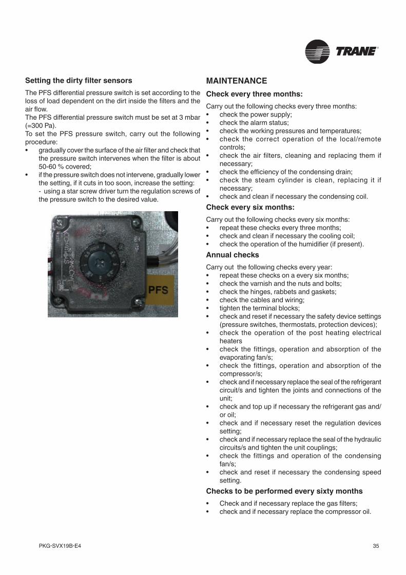
Setting the dirty filter sensorsThe PFS differential pressure switch is set according to the loss of load dependent on the dirt inside the filters and the air flow.The PFS differential pressure switch must be set at 3 mbar (=300 Pa).To set the PFS pressure switch, carry out the following procedure:• gradually cover the surface of the air filter and check that
the pressure switch intervenes when the filter is about 50-60 % covered;
• if the pressure switch does not intervene, gradually lower the setting, if it cuts in too soon, increase the setting:
- using a star screw driver turn the regulation screws of the pressure switch to the desired value.
PKG-SVX19B-E436
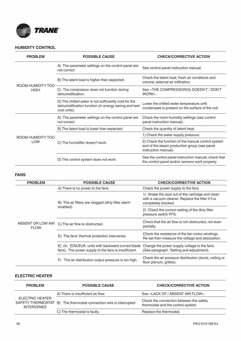
OTHER MODELSTo clean and replace the filters carry out the following procedures:• open the front panels of the machine;• remove the filter blocking supports;
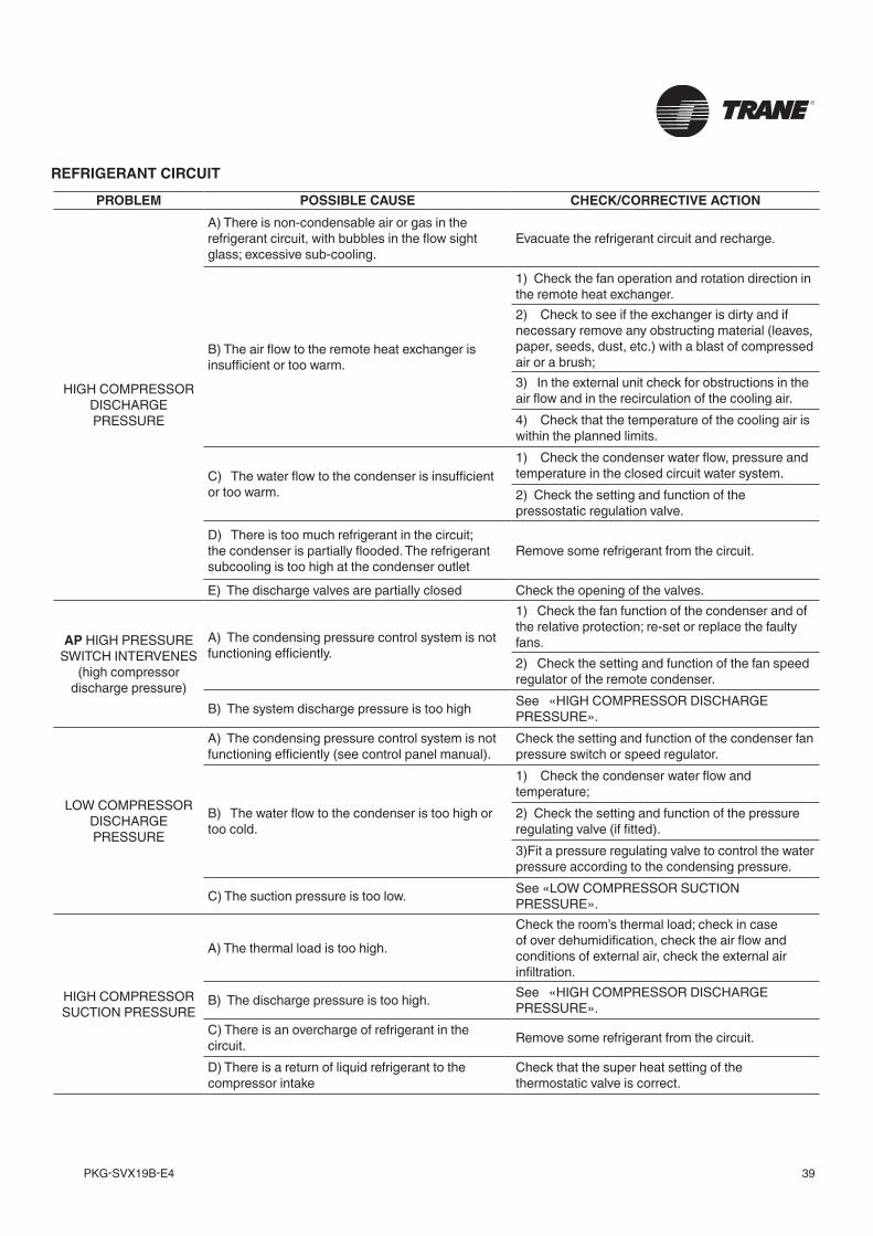
• remove the filters checking the direction of the air flow indicated on the label of each filter;
• clean them using a blast of compressed air or replace them;
• reposition the filters in the unit checking the direction of the air flow which was previously noted;
• reposition the filter blocking supports.
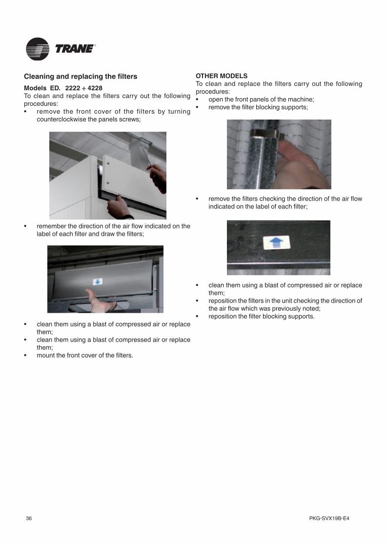
Cleaning and replacing the filtersModels ED. 2222 ÷ 4228To clean and replace the filters carry out the following procedures:• remove the front cover of the filters by turning
counterclockwise the panels screws;
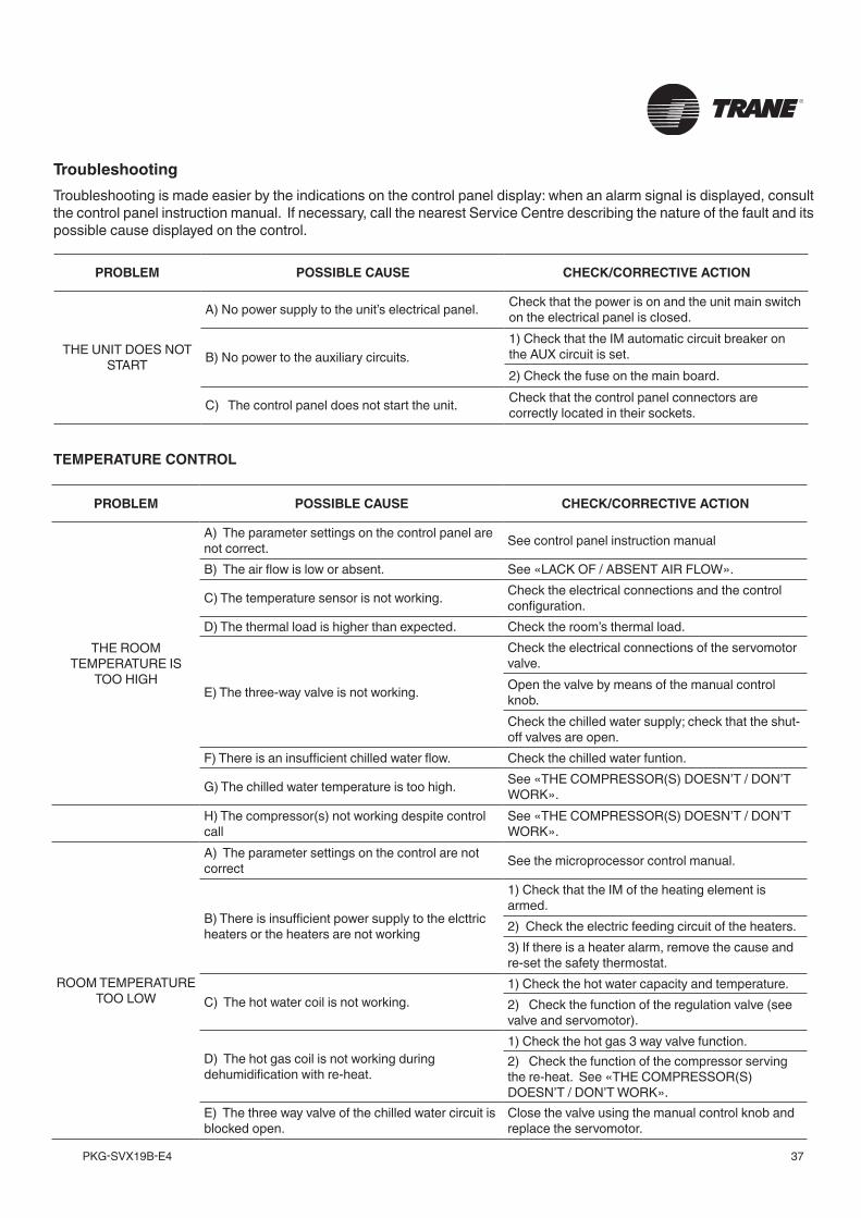
• remember the direction of the air flow indicated on the label of each filter and draw the filters;
• clean them using a blast of compressed air or replace them;
• clean them using a blast of compressed air or replace them;
• mount the front cover of the filters.
37PKG-SVX19B-E4
PROBLEM POSSIBLE CAUSE CHECK/CORRECTIVE ACTION
THE ROOM TEMPERATURE IS
TOO HIGH
A) The parameter settings on the control panel are not correct. See control panel instruction manual
B) The air flow is low or absent. See «LACK OF / ABSENT AIR FLOW».
C) The temperature sensor is not working. Check the electrical connections and the control configuration.
D) The thermal load is higher than expected. Check the room’s thermal load.
E) The three-way valve is not working.
Check the electrical connections of the servomotor valve. Open the valve by means of the manual control knob. Check the chilled water supply; check that the shut-off valves are open.
F) There is an insufficient chilled water flow. Check the chilled water funtion.
G) The chilled water temperature is too high. See «THE COMPRESSOR(S) DOESN’T / DON’T WORK».
H) The compressor(s) not working despite control call
See «THE COMPRESSOR(S) DOESN’T / DON’T WORK».
ROOM TEMPERATURE TOO LOW
A) The parameter settings on the control are not correct See the microprocessor control manual.
B) There is insufficient power supply to the elcttric heaters or the heaters are not working
1) Check that the IM of the heating element is armed.2) Check the electric feeding circuit of the heaters.3) If there is a heater alarm, remove the cause and re-set the safety thermostat.
C) The hot water coil is not working.1) Check the hot water capacity and temperature.2) Check the function of the regulation valve (see valve and servomotor).
D) The hot gas coil is not working during dehumidification with re-heat.
1) Check the hot gas 3 way valve function.2) Check the function of the compressor serving the re-heat. See «THE COMPRESSOR(S) DOESN’T / DON’T WORK».
E) The three way valve of the chilled water circuit is blocked open.
Close the valve using the manual control knob and replace the servomotor.
PROBLEM POSSIBLE CAUSE CHECK/CORRECTIVE ACTION
THE UNIT DOES NOT START
A) No power supply to the unit’s electrical panel. Check that the power is on and the unit main switch on the electrical panel is closed.
B) No power to the auxiliary circuits.1) Check that the IM automatic circuit breaker on the AUX circuit is set.2) Check the fuse on the main board.
C) The control panel does not start the unit. Check that the control panel connectors are correctly located in their sockets.
TroubleshootingTroubleshooting is made easier by the indications on the control panel display: when an alarm signal is displayed, consult the control panel instruction manual. If necessary, call the nearest Service Centre describing the nature of the fault and its possible cause displayed on the control.
TEMPERATURE CONTROL
PKG-SVX19B-E438
PROBLEM POSSIBLE CAUSE CHECK/CORRECTIVE ACTION
ROOM HUMIDITY TOO HIGH
A) The parameter settings on the control panel are not correct. See control panel instruction manual.
B) The latent load is higher then expected. Check the latent load, fresh air conditions and volume; external air infiltration.
C) The compressor does not function during dehumidification.
See «THE COMPRESSOR(S) DOESN’T / DON’T WORK».
D) The chilled water is not sufficiently cold for the dehumidification function (in energy saving and twin cool units).
Lower the chilled water temperature until condensate is present on the surface of the coil.
ROOM HUMIDITY TOO LOW
A) The parameter settings on the control panel are not correct.
Check the room humidity settings (see control panel instruction manual).
B) The latent load is lower than expected. Check the quantity of latent heat.
C) The humidifier doesn’t work.
1) Check the water supply pressure.2) Check the function of the manual control system and of the steam production group (see panel instruction manual).
D) The control system does not work. See the control panel instruction manual; check that the control panel and/or sensors work properly.
PROBLEM POSSIBLE CAUSE CHECK/CORRECTIVE ACTION
ABSENT OR LOW AIR FLOW
A) There is no power to the fans. Check the power supply to the fans
B) The air filters are clogged (dirty filter alarm enabled).
1) Shake the dust out of the cartridge and clean with a vacuum cleaner. Replace the filter if it is completely blocked.
2) Check the correct setting of the dirty filter pressure switch PFS.
C) The air flow is obstructed. Check that the air flow is not obstructed, not even partially.
D) The fans’ thermal protection intervenes. Check the resistance of the fan motor windings. Re-set then measure the voltage and absorption.
E) (In EDA/EUA units with backward curved blade fans). The power supply to the fans is insufficient.
Change the power supply voltage to the fans.(See paragraph. ‘Setting and adjustment).
F) The air distribution output pressure is too high. Check the air pressure distribution (ducts, ceiling or floor plenum, grilles).
PROBLEM POSSIBLE CAUSE CHECK/CORRECTIVE ACTION
ELECTRIC HEATER SAFETY THERMOSTAT
INTERVENES
A) There is insufficient air flow. See «LACK OF / ABSENT AIR FLOW».
B) The thermostat connection wire is interrupted Check the connection between the safety thermostat and the control system.
C) The thermostat is faulty. Replace the thermostat.
HUMIDITY CONTROL
FANS
ELECTRIC HEATER
39PKG-SVX19B-E4
PROBLEM POSSIBLE CAUSE CHECK/CORRECTIVE ACTION
HIGH COMPRESSOR DISCHARGE PRESSURE
A) There is non-condensable air or gas in the refrigerant circuit, with bubbles in the flow sight glass; excessive sub-cooling.
Evacuate the refrigerant circuit and recharge.
B) The air flow to the remote heat exchanger is insufficient or too warm.
1) Check the fan operation and rotation direction in the remote heat exchanger.2) Check to see if the exchanger is dirty and if necessary remove any obstructing material (leaves, paper, seeds, dust, etc.) with a blast of compressed air or a brush;3) In the external unit check for obstructions in the air flow and in the recirculation of the cooling air.4) Check that the temperature of the cooling air is within the planned limits.
C) The water flow to the condenser is insufficient or too warm.
1) Check the condenser water flow, pressure and temperature in the closed circuit water system.2) Check the setting and function of the pressostatic regulation valve.
D) There is too much refrigerant in the circuit; the condenser is partially flooded. The refrigerant subcooling is too high at the condenser outlet
Remove some refrigerant from the circuit.
E) The discharge valves are partially closed Check the opening of the valves.
AP HIGH PRESSURE SWITCH INTERVENES
(high compressor discharge pressure)
A) The condensing pressure control system is not functioning efficiently.
1) Check the fan function of the condenser and of the relative protection; re-set or replace the faulty fans.2) Check the setting and function of the fan speed regulator of the remote condenser.
B) The system discharge pressure is too high See «HIGH COMPRESSOR DISCHARGE PRESSURE».
LOW COMPRESSOR DISCHARGE PRESSURE
A) The condensing pressure control system is not functioning efficiently (see control panel manual).
Check the setting and function of the condenser fan pressure switch or speed regulator.
B) The water flow to the condenser is too high or too cold.
1) Check the condenser water flow and temperature;2) Check the setting and function of the pressure regulating valve (if fitted).3)Fit a pressure regulating valve to control the water pressure according to the condensing pressure.
C) The suction pressure is too low. See «LOW COMPRESSOR SUCTION PRESSURE».
HIGH COMPRESSOR SUCTION PRESSURE
A) The thermal load is too high.
Check the room’s thermal load; check in case of over dehumidification, check the air flow and conditions of external air, check the external air infiltration.
B) The discharge pressure is too high. See «HIGH COMPRESSOR DISCHARGE PRESSURE».
C) There is an overcharge of refrigerant in the circuit. Remove some refrigerant from the circuit.
D) There is a return of liquid refrigerant to the compressor intake
Check that the super heat setting of the thermostatic valve is correct.
REFRIGERANT CIRCUIT
PROBLEM POSSIBLE CAUSE CHECK/CORRECTIVE ACTION
ABSENT OR LOW AIR FLOW
A) There is no power to the fans. Check the power supply to the fans
B) The air filters are clogged (dirty filter alarm enabled).
1) Shake the dust out of the cartridge and clean with a vacuum cleaner. Replace the filter if it is completely blocked.
2) Check the correct setting of the dirty filter pressure switch PFS.
C) The air flow is obstructed. Check that the air flow is not obstructed, not even partially.
D) The fans’ thermal protection intervenes. Check the resistance of the fan motor windings. Re-set then measure the voltage and absorption.
E) (In EDA/EUA units with backward curved blade fans). The power supply to the fans is insufficient.
Change the power supply voltage to the fans.(See paragraph. ‘Setting and adjustment).
F) The air distribution output pressure is too high. Check the air pressure distribution (ducts, ceiling or floor plenum, grilles).
PKG-SVX19B-E440
PROBLEM POSSIBLE CAUSE CHECK/CORRECTIVE ACTION
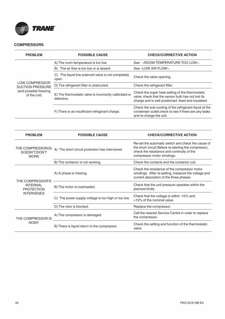
LOW COMPRESSOR SUCTION PRESSURE (and possible freezing
of the coil)
A) The room temperature is too low. See «ROOM TEMPERATURE TOO LOW».B) The air flow is too low or is absent. See «LOW AIR FLOW».
C) The liquid line solenoid valve is not completely open. Check the valve opening.
D) The refrigerant filter is obstructed. Check the refrigerant filter.
E) The thermostatic valve is incorrectly calibrated or defective.
Check the super heat setting of the thermostatic valve; check that the sensor bulb has not lost its charge and is well positioned, fixed and insulated.
F) There is an insufficient refrigerant charge.Check the sub-cooling of the refrigerant liquid at the condenser outlet;check to see if there are any leaks and re-charge the unit.
PROBLEM POSSIBLE CAUSE CHECK/CORRECTIVE ACTION
THE COMPRESSOR(S) DOESN’T/DON’T
WORK
A) The short circuit protection has intervened.
Re-set the automatic switch and check the cause of the short circuit.Before re-starting the compressor, check the resistance and continuity of the compressor motor windings.
B) The contactor is not working. Check the contacts and the contactor coil.
THE COMPRESSOR’S INTERNAL
PROTECTION INTERVENES
A) A phase is missing.Check the resistance of the compressor motor windings. After re-setting, measure the voltage and current absorption of the three phases.
B) The motor is overloaded. Check that the unit pressure operates within the planned limits.
C) The power supply voltage is too high or too low. Check that the voltage is within -10% and+10% of the nominal value.
D) The rotor is blocked. Replace the compressor.
THE COMPRESSOR IS NOISY
A) The compressor is damaged. Call the nearest Service Centre in order to replace the compressor.
B) There is liquid return to the compressor. Check the setting and function of the thermostatic valve.
COMPRESSORS
41PKG-SVX19B-E4
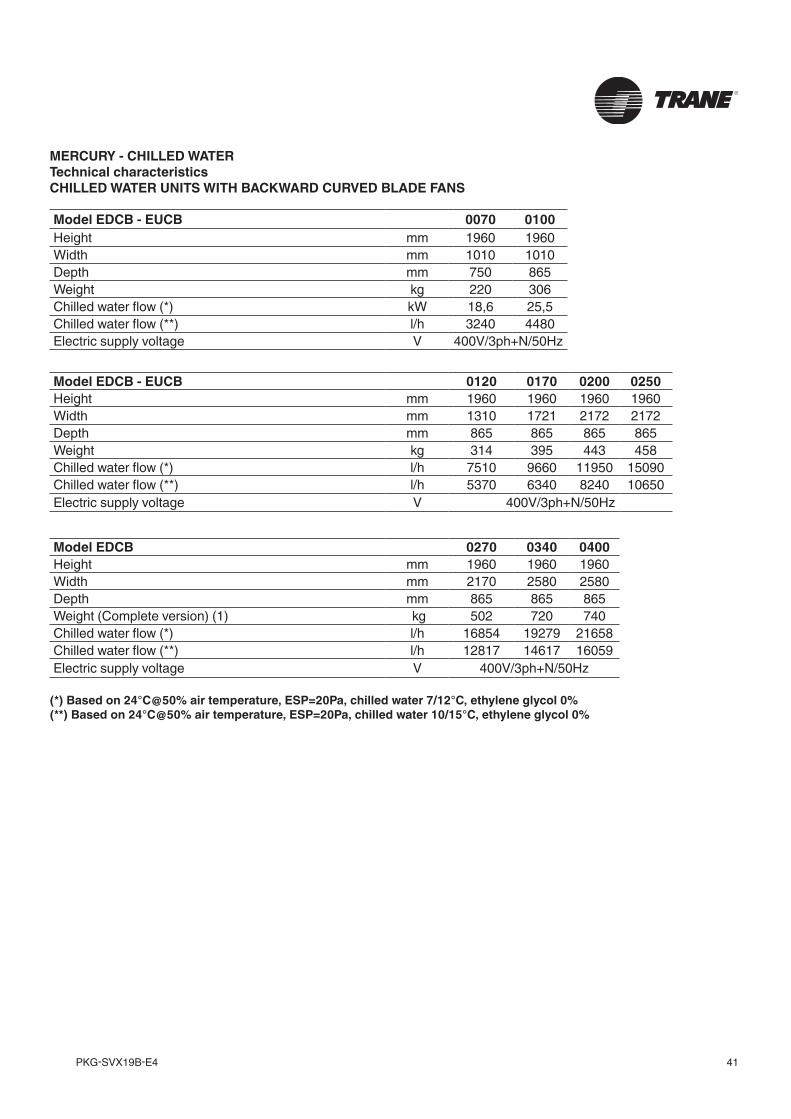
MERCURY - CHILLED WATERTechnical characteristicsCHILLED WATER UNITS WITH BACKWARD CURVED BLADE FANS
Model EDCB - EUCB 0120 0170 0200 0250Height mm 1960 1960 1960 1960Width mm 1310 1721 2172 2172Depth mm 865 865 865 865Weight kg 314 395 443 458Chilled water flow (*) l/h 7510 9660 11950 15090Chilled water flow (**) l/h 5370 6340 8240 10650Electric supply voltage V 400V/3ph+N/50Hz
Model EDCB - EUCB 0070 0100Height mm 1960 1960Width mm 1010 1010Depth mm 750 865Weight kg 220 306Chilled water flow (*) kW 18,6 25,5Chilled water flow (**) l/h 3240 4480Electric supply voltage V 400V/3ph+N/50Hz
(*) Based on 24°C@50% air temperature, ESP=20Pa, chilled water 7/12°C, ethylene glycol 0%(**) Based on 24°C@50% air temperature, ESP=20Pa, chilled water 10/15°C, ethylene glycol 0%
Model EDCB 0270 0340 0400Height mm 1960 1960 1960Width mm 2170 2580 2580Depth mm 865 865 865Weight (Complete version) (1) kg 502 720 740Chilled water flow (*) l/h 16854 19279 21658Chilled water flow (**) l/h 12817 14617 16059Electric supply voltage V 400V/3ph+N/50Hz
PKG-SVX19B-E442
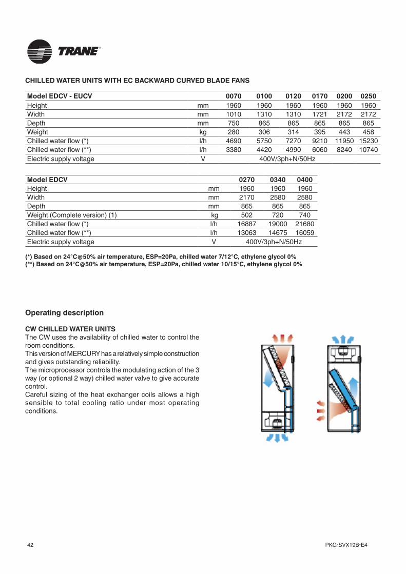
CW CHILLED WATER UNITSThe CW uses the availability of chilled water to control the room conditions.This version of MERCURY has a relatively simple construction and gives outstanding reliability.The microprocessor controls the modulating action of the 3 way (or optional 2 way) chilled water valve to give accurate control.Careful sizing of the heat exchanger coils allows a high sensible to total cooling ratio under most operating conditions.
Operating description
Model EDCV 0270 0340 0400Height mm 1960 1960 1960Width mm 2170 2580 2580Depth mm 865 865 865Weight (Complete version) (1) kg 502 720 740Chilled water flow (*) l/h 16887 19000 21680Chilled water flow (**) l/h 13063 14675 16059Electric supply voltage V 400V/3ph+N/50Hz
Model EDCV - EUCV 0070 0100 0120 0170 0200 0250Height mm 1960 1960 1960 1960 1960 1960Width mm 1010 1310 1310 1721 2172 2172Depth mm 750 865 865 865 865 865Weight kg 280 306 314 395 443 458Chilled water flow (*) l/h 4690 5750 7270 9210 11950 15230Chilled water flow (**) l/h 3380 4420 4990 6060 8240 10740Electric supply voltage V 400V/3ph+N/50Hz
CHILLED WATER UNITS WITH EC BACKWARD CURVED BLADE FANS
(*) Based on 24°C@50% air temperature, ESP=20Pa, chilled water 7/12°C, ethylene glycol 0%(**) Based on 24°C@50% air temperature, ESP=20Pa, chilled water 10/15°C, ethylene glycol 0%
43PKG-SVX19B-E4
Name and description of the main components
Description of the componentsA - User terminalAllows the unit to be turned on or off and the configuration and visualization of the condition of the machine.• A1 LCD Display• A2 ALARM key: visualisation and re-set of alarms; when
the alarm is activated, it flashes red.• A3 PRG key : access to the configuration menu• A4 ESC key : exit from the screens• A5 UP key : scroll through the menu• A6 ENTER key : confirm• A7 DOWN key: scroll through the menu
B - Electrical panel doorAllows access to the electrical panel of the machine
A User terminalB Electrical panel doorC Cover panelsD Electrical panelE FiltersF FansG Chilled water valve
A5
A6
A7
A2
A3
A4
A1
A
C
B
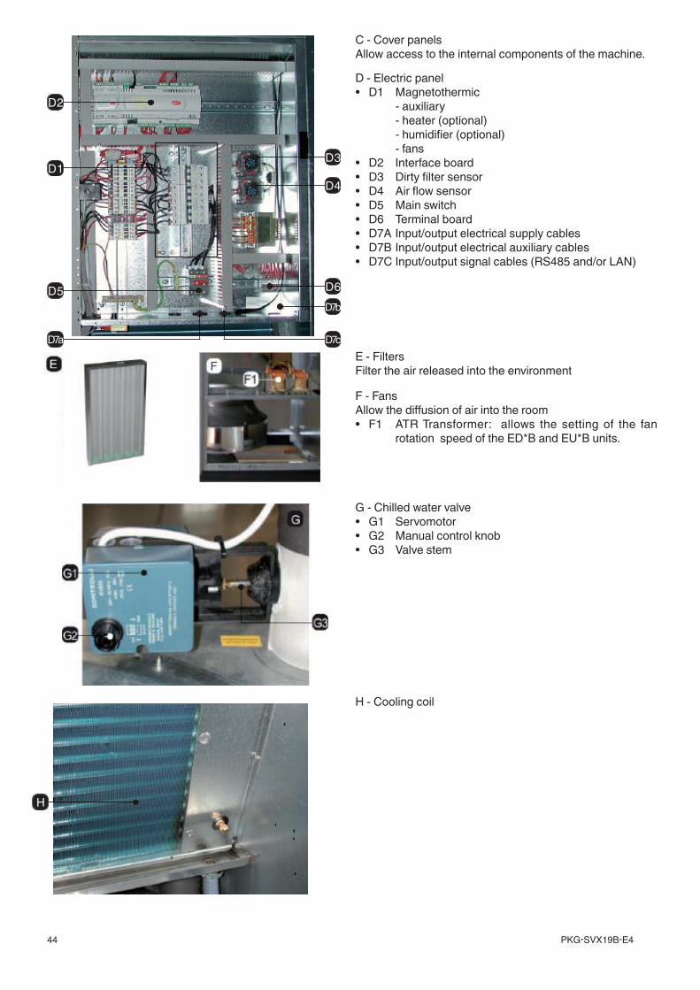
PKG-SVX19B-E444
G - Chilled water valve• G1 Servomotor• G2 Manual control knob• G3 Valve stem
H - Cooling coil
C - Cover panelsAllow access to the internal components of the machine.
E - FiltersFilter the air released into the environment
F - FansAllow the diffusion of air into the room• F1 ATR Transformer: allows the setting of the fan
rotation speed of the ED*B and EU*B units.
D - Electric panel• D1 Magnetothermic - auxiliary - heater (optional) - humidifier (optional) - fans• D2 Interface board• D3 Dirty filter sensor• D4 Air flow sensor• D5 Main switch• D6 Terminal board• D7A Input/output electrical supply cables• D7B Input/output electrical auxiliary cables• D7C Input/output signal cables (RS485 and/or LAN)
D2
D1
D5
D7a D7c
D7b
D6
D4
D3
H
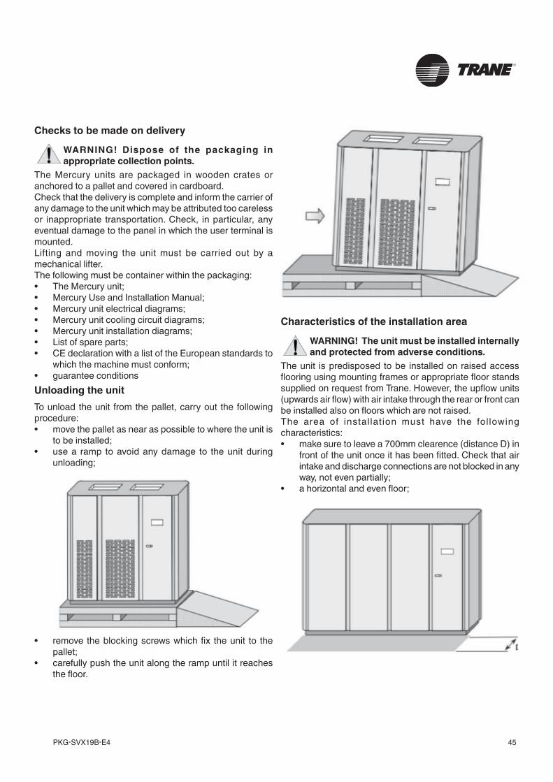
45PKG-SVX19B-E4
Checks to be made on delivery
WARNING! Dispose of the packaging in appropriate collection points.
The Mercury units are packaged in wooden crates or anchored to a pallet and covered in cardboard.Check that the delivery is complete and inform the carrier of any damage to the unit which may be attributed too careless or inappropriate transportation. Check, in particular, any eventual damage to the panel in which the user terminal is mounted.Lifting and moving the unit must be carried out by a mechanical lifter. The following must be container within the packaging:• The Mercury unit;• Mercury Use and Installation Manual;• Mercury unit electrical diagrams;• Mercury unit cooling circuit diagrams;• Mercury unit installation diagrams;• List of spare parts;• CE declaration with a list of the European standards to
which the machine must conform;• guarantee conditionsUnloading the unitTo unload the unit from the pallet, carry out the following procedure:• move the pallet as near as possible to where the unit is
to be installed;• use a ramp to avoid any damage to the unit during
unloading;
• remove the blocking screws which fix the unit to the pallet;
• carefully push the unit along the ramp until it reaches the floor.
Characteristics of the installation area
WARNING! The unit must be installed internally and protected from adverse conditions.
The unit is predisposed to be installed on raised access flooring using mounting frames or appropriate floor stands supplied on request from Trane. However, the upflow units (upwards air flow) with air intake through the rear or front can be installed also on floors which are not raised.The area of instal lat ion must have the fol lowing characteristics:• make sure to leave a 700mm clearence (distance D) in
front of the unit once it has been fitted. Check that air intake and discharge connections are not blocked in any way, not even partially;
• a horizontal and even floor;
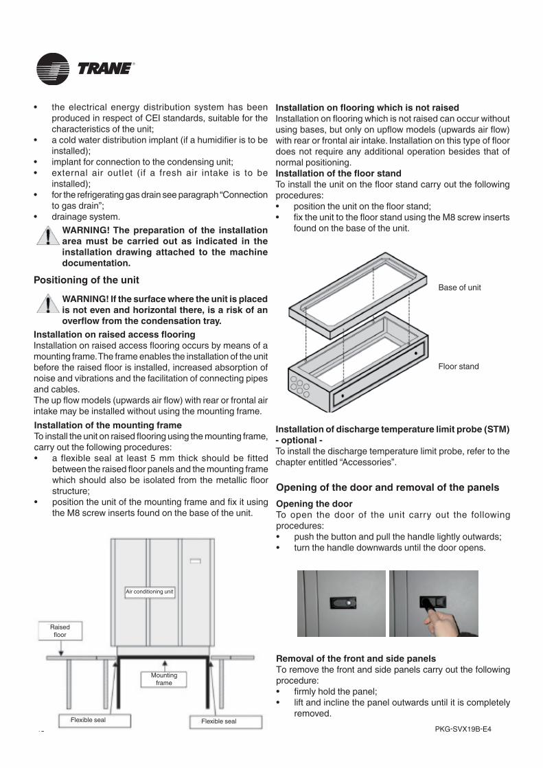
PKG-SVX19B-E446
• the electrical energy distribution system has been produced in respect of CEI standards, suitable for the characteristics of the unit;
• a cold water distribution implant (if a humidifier is to be installed);
• implant for connection to the condensing unit;• external air outlet (if a fresh air intake is to be
installed);• for the refrigerating gas drain see paragraph “Connection
to gas drain”;• drainage system.
WARNING! The preparation of the installation area must be carried out as indicated in the installation drawing attached to the machine documentation.
Positioning of the unit
WARNING! If the surface where the unit is placed is not even and horizontal there, is a risk of an overflow from the condensation tray.
Installation on raised access flooringInstallation on raised access flooring occurs by means of a mounting frame. The frame enables the installation of the unit before the raised floor is installed, increased absorption of noise and vibrations and the facilitation of connecting pipes and cables.The up flow models (upwards air flow) with rear or frontal air intake may be installed without using the mounting frame. Installation of the mounting frameTo install the unit on raised flooring using the mounting frame, carry out the following procedures:• a flexible seal at least 5 mm thick should be fitted
between the raised floor panels and the mounting frame which should also be isolated from the metallic floor structure;
• position the unit of the mounting frame and fix it using the M8 screw inserts found on the base of the unit.
Air conditioning unit
Raisedfloor
Flexible seal Flexible seal
Mountingframe
Installation on flooring which is not raisedInstallation on flooring which is not raised can occur without using bases, but only on upflow models (upwards air flow) with rear or frontal air intake. Installation on this type of floor does not require any additional operation besides that of normal positioning. Installation of the floor standTo install the unit on the floor stand carry out the following procedures:• position the unit on the floor stand;• fix the unit to the floor stand using the M8 screw inserts
found on the base of the unit.
Installation of discharge temperature limit probe (STM) - optional -To install the discharge temperature limit probe, refer to the chapter entitled “Accessories”.
Opening of the door and removal of the panelsOpening the doorTo open the door of the unit carry out the following procedures:• push the button and pull the handle lightly outwards;• turn the handle downwards until the door opens.
Removal of the front and side panelsTo remove the front and side panels carry out the following procedure:• firmly hold the panel;• lift and incline the panel outwards until it is completely
removed.
Base of unit
Floor stand
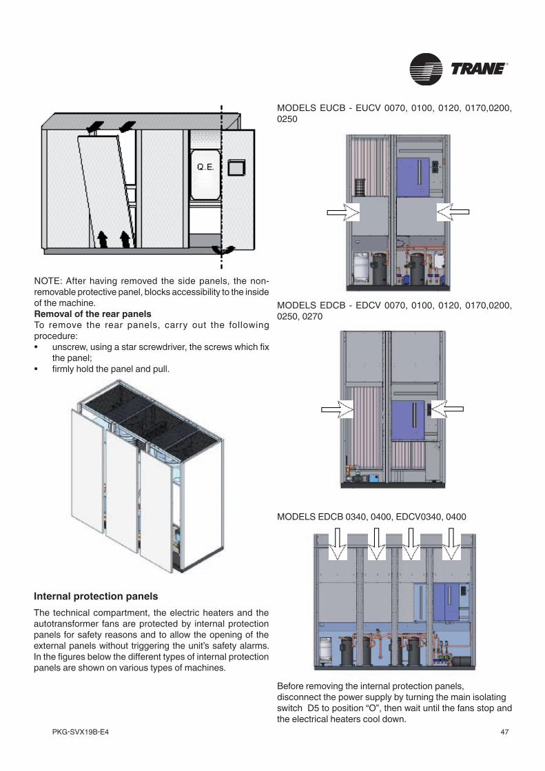
47PKG-SVX19B-E4
NOTE: After having removed the side panels, the non-removable protective panel, blocks accessibility to the inside of the machine.Removal of the rear panelsTo remove the rear panels, carry out the following procedure:• unscrew, using a star screwdriver, the screws which fix
the panel;• firmly hold the panel and pull.
Internal protection panelsThe technical compartment, the electric heaters and the autotransformer fans are protected by internal protection panels for safety reasons and to allow the opening of the external panels without triggering the unit’s safety alarms. In the figures below the different types of internal protection panels are shown on various types of machines.
Before removing the internal protection panels, disconnect the power supply by turning the main isolating switch D5 to position “O”, then wait until the fans stop and the electrical heaters cool down.
MODELS EUCB - EUCV 0070, 0100, 0120, 0170,0200, 0250
MODELS EDCB - EDCV 0070, 0100, 0120, 0170,0200, 0250, 0270
MODELS EDCB 0340, 0400, EDCV0340, 0400
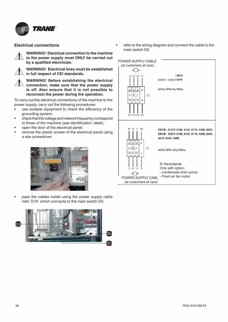
PKG-SVX19B-E448
Electrical connections
WARNING! Electrical connection to the machine to the power supply must ONLY be carried out by a qualified electrician.WARNING! Electrical lines must be established in full respect of CEI standards.WARNING! Before establishing the electrical connection, make sure that the power supply is off. Also ensure that it is not possible to reconnect the power during the operation.
To carry out the electrical connections of the machine to the power supply, carry out the following procedures:• use suitable equipment to check the efficiency of the
grounding system;• check that the voltage and network frequency correspond
to those of the machine (see identification label);• open the door of the electrical panel;• remove the plastic screen of the electrical panel using
a star screwdriver;
POWER SUPPLY CABLE (at customers at care)
POWER SUPPLY CABLE (at customers at care)
N: NeutralpoleOnly with option:- condensate drain pump- Fresh air fan motor
• pass the cables inside using the power supply cable inlet D7A which connects to the main switch D5;
• refer to the wiring diagram and connect the cable to the main switch D5.
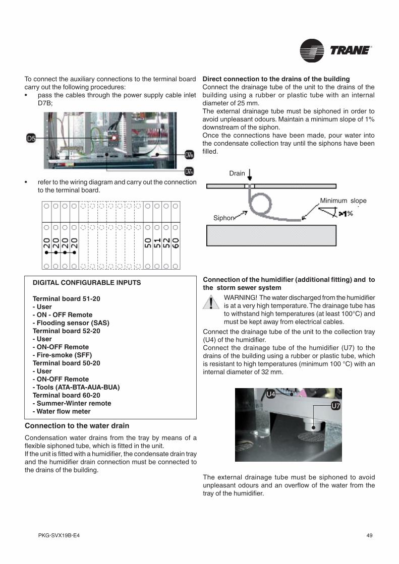
49PKG-SVX19B-E4
Direct connection to the drains of the building Connect the drainage tube of the unit to the drains of the building using a rubber or plastic tube with an internal diameter of 25 mm.The external drainage tube must be siphoned in order to avoid unpleasant odours. Maintain a minimum slope of 1% downstream of the siphon.Once the connections have been made, pour water into the condensate collection tray until the siphons have been filled.
Connection to the water drainCondensation water drains from the tray by means of a flexible siphoned tube, which is fitted in the unit.If the unit is fitted with a humidifier, the condensate drain tray and the humidifier drain connection must be connected to the drains of the building.
To connect the auxiliary connections to the terminal board carry out the following procedures:• pass the cables through the power supply cable inlet
D7B;
DIGITAL CONFIGURABLE INPUTS
Terminal board 51-20- User- ON - OFF Remote- Flooding sensor (SAS)Terminal board 52-20- User- ON-OFF Remote- Fire-smoke (SFF)Terminal board 50-20- User- ON-OFF Remote- Tools (ATA-BTA-AUA-BUA)Terminal board 60-20- Summer-Winter remote- Water flow meter
Connection of the humidifier (additional fitting) and to the storm sewer system
WARNING! The water discharged from the humidifier is at a very high temperature. The drainage tube has to withstand high temperatures (at least 100°C) and must be kept away from electrical cables.
Connect the drainage tube of the unit to the collection tray (U4) of the humidifier.Connect the drainage tube of the humidifier (U7) to the drains of the building using a rubber or plastic tube, which is resistant to high temperatures (minimum 100 °C) with an internal diameter of 32 mm.
The external drainage tube must be siphoned to avoid unpleasant odours and an overflow of the water from the tray of the humidifier.
• refer to the wiring diagram and carry out the connection to the terminal board.
Minimum slope
Drain
Siphon
U7U4
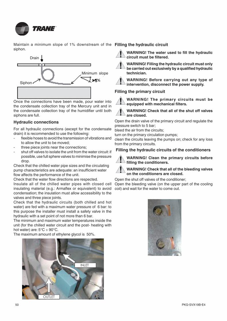
PKG-SVX19B-E450
Once the connections have been made, pour water into the condensate collection tray of the Mercury unit and in the condensate collection tray of the humidifier until both siphons are full.
OUTLET
INLET
Filling the hydraulic circuit
WARNING! The water used to fill the hydraulic circuit must be filtered.WARNING! Filling the hydraulic circuit must only be carried out exclusively by a qualified hydraulic technician.WARNING! Before carrying out any type of intervention, disconnect the power supply.
Filling the primary circuit
WARNING! The primary circuits must be equipped with mechanical filters.WARNING! Check that all of the shut off valves are closed.
Open the drain valve of the primary circuit and regulate the pressure switch to 5 bar;bleed the air from the circuits;turn on the primary circulation pumps; clean the circuits leaving the pumps on; check for any loss from the primary circuits. Filling the hydraulic circuits of the conditioners
WARNING! Clean the primary circuits before filling the conditioners.WARNING! Check that all of the bleeding valves on the conditioners are closed.
Open the shut off valves of the conditioner;Open the bleeding valve (on the upper part of the cooling coil) and wait for the water to come out.
Hydraulic connectionsFor all hydraulic connections (except for the condensate drain) it is recommended to use the following:- flexible hoses to avoid the transmission of vibrations and
to allow the unit to be moved;- three piece joints near the connections;- shut off valves to isolate the unit from the water circuit: if
possible, use full sphere valves to minimise the pressure drop.
Check that the chilled water pipe sizes and the circulatingpump characteristics are adequate: an insufficient waterflow affects the performance of the unit.Check that the water flow directions are respected.Insulate all of the chilled water pipes with closed cell insulating material (e.g.: Armaflex or equivalent) to avoid condensation; the insulation must allow accessibility to the valves and three piece joints.Check that the hydraulic circuits (both chilled and hot water) are fed with a maximum water pressure of 6 bar: to this purpose the installer must install a safety valve in the hydraulic with a set point of not more than 6 bar.The minimum and maximum water temperatures inside the unit (for the chilled water circuit and the post- heating with hot water) are: 5°C ÷ 90°C.The maximum amount of ethylene glycol is 50%.
Maintain a minimum slope of 1% downstream of the siphon.
Minimum slope
Drain
Siphon
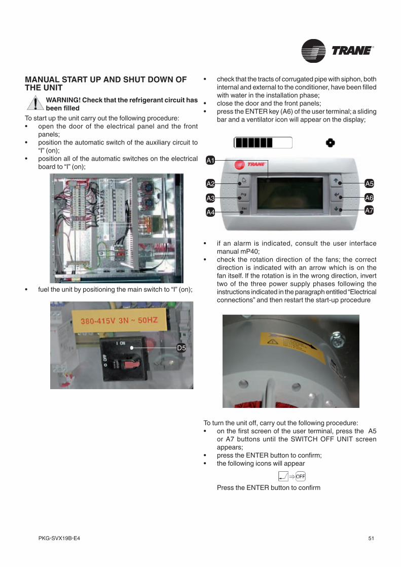
51PKG-SVX19B-E4
MANUAL START UP AND SHUT DOWN OF THE UNIT
WARNING! Check that the refrigerant circuit has been filled
To start up the unit carry out the following procedure:• open the door of the electrical panel and the front
panels;• position the automatic switch of the auxiliary circuit to
“I” (on);• position all of the automatic switches on the electrical
board to “I” (on);
• fuel the unit by positioning the main switch to “I” (on);
• check that the tracts of corrugated pipe with siphon, both internal and external to the conditioner, have been filled with water in the installation phase;
• close the door and the front panels;• press the ENTER key (A6) of the user terminal; a sliding
bar and a ventilator icon will appear on the display;
• if an alarm is indicated, consult the user interface manual mP40;
• check the rotation direction of the fans; the correct direction is indicated with an arrow which is on the fan itself. If the rotation is in the wrong direction, invert two of the three power supply phases following the instructions indicated in the paragraph entitled “Electrical connections” and then restart the start-up procedure
To turn the unit off, carry out the following procedure:• on the first screen of the user terminal, press the A5
or A7 buttons until the SWITCH OFF UNIT screen appears;
• press the ENTER button to confirm;• the following icons will appear
Press the ENTER button to confirm
D5
A5
A6
A7
A2
A3
A4
A1
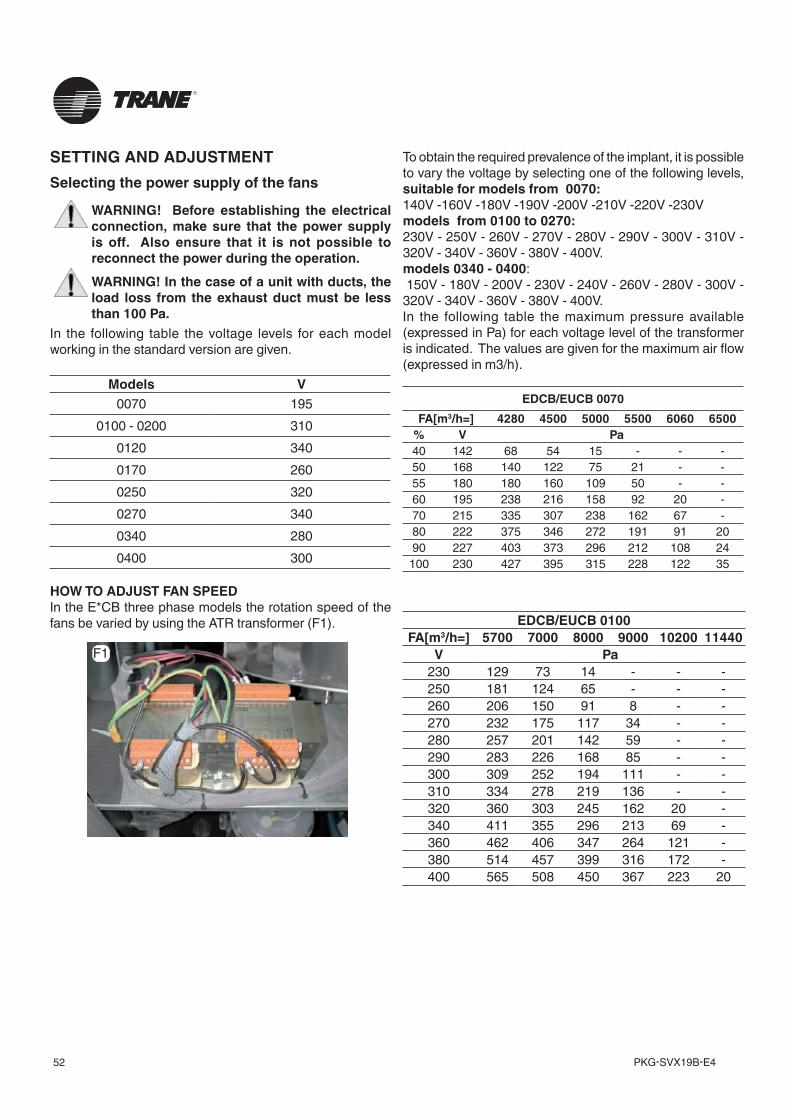
PKG-SVX19B-E452
To obtain the required prevalence of the implant, it is possible to vary the voltage by selecting one of the following levels, suitable for models from 0070:140V -160V -180V -190V -200V -210V -220V -230Vmodels from 0100 to 0270:230V - 250V - 260V - 270V - 280V - 290V - 300V - 310V - 320V - 340V - 360V - 380V - 400V.models 0340 - 0400: 150V - 180V - 200V - 230V - 240V - 260V - 280V - 300V - 320V - 340V - 360V - 380V - 400V. In the following table the maximum pressure available (expressed in Pa) for each voltage level of the transformer is indicated. The values are given for the maximum air flow (expressed in m3/h).
SETTING AND ADJUSTMENTSelecting the power supply of the fans
WARNING! Before establishing the electrical connection, make sure that the power supply is off. Also ensure that it is not possible to reconnect the power during the operation.WARNING! In the case of a unit with ducts, the load loss from the exhaust duct must be less than 100 Pa.
In the following table the voltage levels for each model working in the standard version are given.
Models V0070 195
0100 - 0200 3100120 3400170 2600250 3200270 3400340 2800400 300
HOW TO ADJUST FAN SPEEDIn the E*CB three phase models the rotation speed of the fans be varied by using the ATR transformer (F1). EDCB/EUCB 0100
FA[m3/h=] 5700 7000 8000 9000 10200 11440V Pa
230 129 73 14 - - -250 181 124 65 - - -260 206 150 91 8 - -270 232 175 117 34 - -280 257 201 142 59 - -290 283 226 168 85 - -300 309 252 194 111 - -310 334 278 219 136 - -320 360 303 245 162 20 -340 411 355 296 213 69 -360 462 406 347 264 121 -380 514 457 399 316 172 -400 565 508 450 367 223 20
EDCB/EUCB 0070FA[m3/h=] 4280 4500 5000 5500 6060 6500
% V Pa40 142 68 54 15 - - -50 168 140 122 75 21 - -55 180 180 160 109 50 - -60 195 238 216 158 92 20 -70 215 335 307 238 162 67 -80 222 375 346 272 191 91 2090 227 403 373 296 212 108 24
100 230 427 395 315 228 122 35
F1
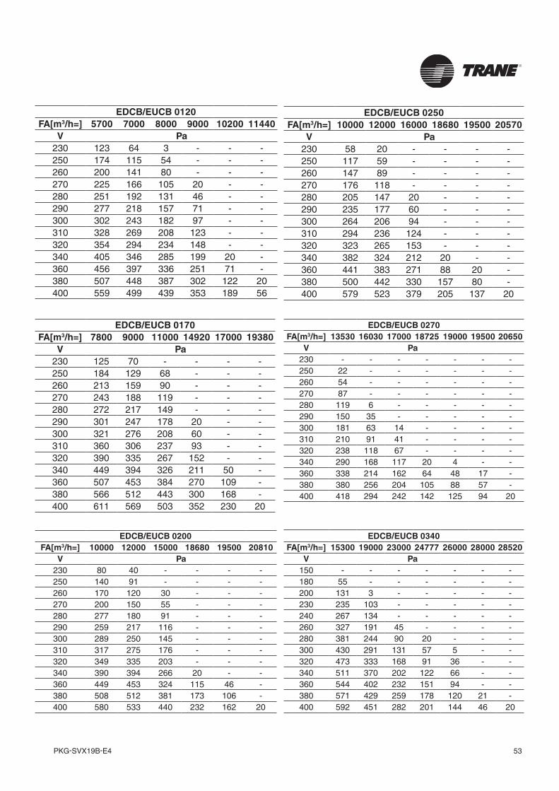
53PKG-SVX19B-E4
EDCB/EUCB 0200FA[m3/h=] 10000 12000 15000 18680 19500 20810
V Pa230 80 40 - - - -250 140 91 - - - -260 170 120 30 - - -270 200 150 55 - - -280 277 180 91 - - -290 259 217 116 - - -300 289 250 145 - - -310 317 275 176 - - -320 349 335 203 - - -340 390 394 266 20 - -360 449 453 324 115 46 -380 508 512 381 173 106 -400 580 533 440 232 162 20
EDCB/EUCB 0250FA[m3/h=] 10000 12000 16000 18680 19500 20570
V Pa230 58 20 - - - -250 117 59 - - - -260 147 89 - - - -270 176 118 - - - -280 205 147 20 - - -290 235 177 60 - - -300 264 206 94 - - -310 294 236 124 - - -320 323 265 153 - - -340 382 324 212 20 - -360 441 383 271 88 20 -380 500 442 330 157 80 -400 579 523 379 205 137 20
EDCB/EUCB 0270FA[m3/h=] 13530 16030 17000 18725 19000 19500 20650
V Pa230 - - - - - - -250 22 - - - - - -260 54 - - - - - -270 87 - - - - - -280 119 6 - - - - -290 150 35 - - - - -300 181 63 14 - - - -310 210 91 41 - - - -320 238 118 67 - - - -340 290 168 117 20 4 - -360 338 214 162 64 48 17 -380 380 256 204 105 88 57 -400 418 294 242 142 125 94 20
EDCB/EUCB 0340FA[m3/h=] 15300 19000 23000 24777 26000 28000 28520
V Pa150 - - - - - - -180 55 - - - - - -200 131 3 - - - - -230 235 103 - - - - -240 267 134 - - - - -260 327 191 45 - - - -280 381 244 90 20 - - -300 430 291 131 57 5 - -320 473 333 168 91 36 - -340 511 370 202 122 66 - -360 544 402 232 151 94 - -380 571 429 259 178 120 21 -400 592 451 282 201 144 46 20
EDCB/EUCB 0120FA[m3/h=] 5700 7000 8000 9000 10200 11440
V Pa230 123 64 3 - - -250 174 115 54 - - -260 200 141 80 - - -270 225 166 105 20 - -280 251 192 131 46 - -290 277 218 157 71 - -300 302 243 182 97 - -310 328 269 208 123 - -320 354 294 234 148 - -340 405 346 285 199 20 -360 456 397 336 251 71 -380 507 448 387 302 122 20400 559 499 439 353 189 56
EDCB/EUCB 0170FA[m3/h=] 7800 9000 11000 14920 17000 19380
V Pa230 125 70 - - - -250 184 129 68 - - -260 213 159 90 - - -270 243 188 119 - - -280 272 217 149 - - -290 301 247 178 20 - -300 321 276 208 60 - -310 360 306 237 93 - -320 390 335 267 152 - -340 449 394 326 211 50 -360 507 453 384 270 109 -380 566 512 443 300 168 -400 611 569 503 352 230 20
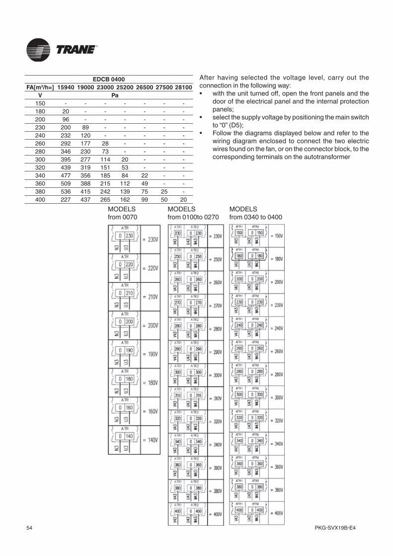
PKG-SVX19B-E454
After having selected the voltage level, carry out the connection in the following way:• with the unit turned off, open the front panels and the
door of the electrical panel and the internal protection panels;
• select the supply voltage by positioning the main switch to “0” (D5);
• Follow the diagrams displayed below and refer to the wiring diagram enclosed to connect the two electric wires found on the fan, or on the connector block, to the corresponding terminals on the autotransformer
MODELSfrom 0100to 0270
MODELS from 0340 to 0400
MODELS from 0070
EDCB 0400FA[m3/h=] 15940 19000 23000 25200 26500 27500 28100
V Pa150 - - - - - - -180 20 - - - - - -200 96 - - - - - -230 200 89 - - - - -240 232 120 - - - - -260 292 177 28 - - - -280 346 230 73 - - - -300 395 277 114 20 - - -320 439 319 151 53 - - -340 477 356 185 84 22 - -360 509 388 215 112 49 - -380 536 415 242 139 75 25 -400 227 437 265 162 99 50 20
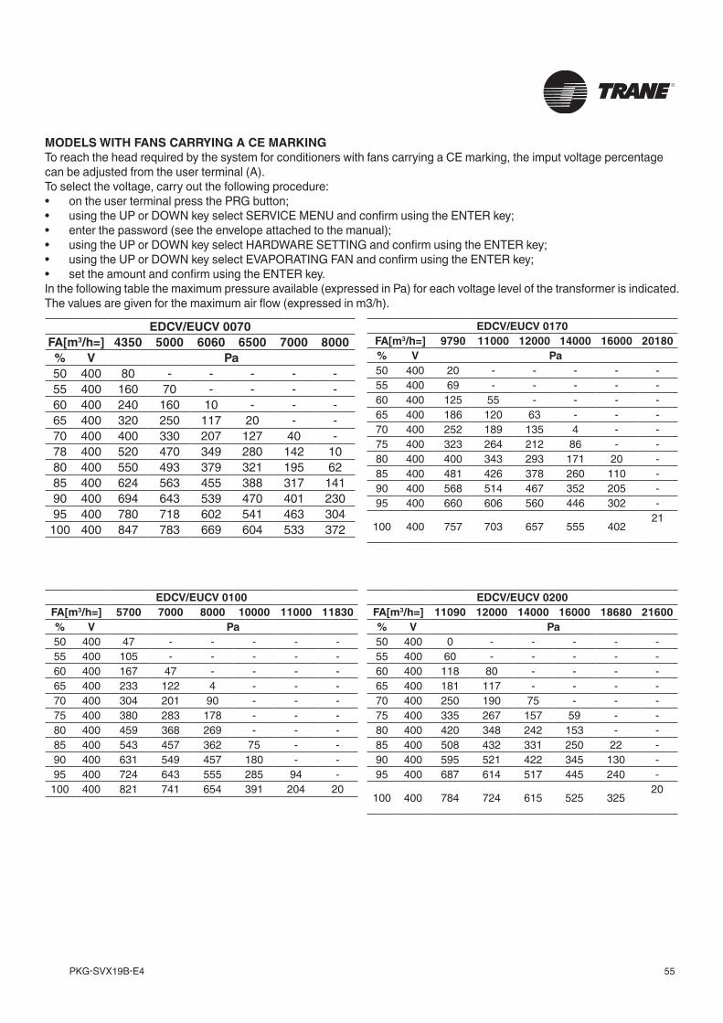
55PKG-SVX19B-E4
MODELS WITH FANS CARRYING A CE MARKINGTo reach the head required by the system for conditioners with fans carrying a CE marking, the imput voltage percentagecan be adjusted from the user terminal (A).To select the voltage, carry out the following procedure:• on the user terminal press the PRG button;• using the UP or DOWN key select SERVICE MENU and confirm using the ENTER key;• enter the password (see the envelope attached to the manual);• using the UP or DOWN key select HARDWARE SETTING and confirm using the ENTER key;• using the UP or DOWN key select EVAPORATING FAN and confirm using the ENTER key;• set the amount and confirm using the ENTER key.In the following table the maximum pressure available (expressed in Pa) for each voltage level of the transformer is indicated. The values are given for the maximum air flow (expressed in m3/h).
EDCV/EUCV 0200FA[m3/h=] 11090 12000 14000 16000 18680 21600% V Pa50 400 0 - - - - -55 400 60 - - - - -60 400 118 80 - - - -65 400 181 117 - - - -70 400 250 190 75 - - -75 400 335 267 157 59 - -80 400 420 348 242 153 - -85 400 508 432 331 250 22 -90 400 595 521 422 345 130 -95 400 687 614 517 445 240 -
100 400 784 724 615 525 32520
EDCV/EUCV 0100FA[m3/h=] 5700 7000 8000 10000 11000 11830% V Pa50 400 47 - - - - -55 400 105 - - - - -60 400 167 47 - - - -65 400 233 122 4 - - -70 400 304 201 90 - - -75 400 380 283 178 - - -80 400 459 368 269 - - -85 400 543 457 362 75 - -90 400 631 549 457 180 - -95 400 724 643 555 285 94 -
100 400 821 741 654 391 204 20
EDCV/EUCV 0170FA[m3/h=] 9790 11000 12000 14000 16000 20180% V Pa50 400 20 - - - - -55 400 69 - - - - -60 400 125 55 - - - -65 400 186 120 63 - - -70 400 252 189 135 4 - -75 400 323 264 212 86 - -80 400 400 343 293 171 20 -85 400 481 426 378 260 110 -90 400 568 514 467 352 205 -95 400 660 606 560 446 302 -
100 400 757 703 657 555 40221
EDCV/EUCV 0070FA[m3/h=] 4350 5000 6060 6500 7000 8000% V Pa50 400 80 - - - - -55 400 160 70 - - - -60 400 240 160 10 - - -65 400 320 250 117 20 - -70 400 400 330 207 127 40 -78 400 520 470 349 280 142 1080 400 550 493 379 321 195 6285 400 624 563 455 388 317 14190 400 694 643 539 470 401 23095 400 780 718 602 541 463 304
100 400 847 783 669 604 533 372
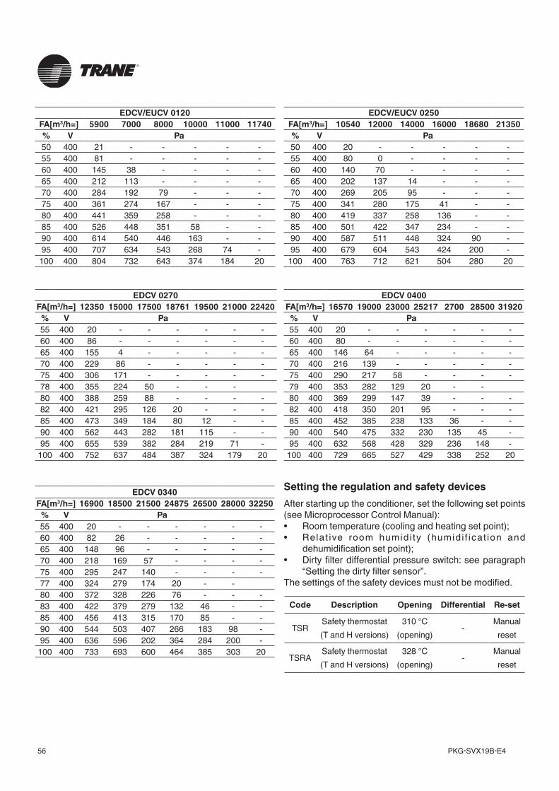
PKG-SVX19B-E456
EDCV/EUCV 0250FA[m3/h=] 10540 12000 14000 16000 18680 21350% V Pa50 400 20 - - - - -55 400 80 0 - - - -60 400 140 70 - - - -65 400 202 137 14 - - -70 400 269 205 95 - - -75 400 341 280 175 41 - -80 400 419 337 258 136 - -85 400 501 422 347 234 - -90 400 587 511 448 324 90 -95 400 679 604 543 424 200 -
100 400 763 712 621 504 280 20
EDCV/EUCV 0120FA[m3/h=] 5900 7000 8000 10000 11000 11740% V Pa50 400 21 - - - - -55 400 81 - - - - -60 400 145 38 - - - -65 400 212 113 - - - -70 400 284 192 79 - - -75 400 361 274 167 - - -80 400 441 359 258 - - -85 400 526 448 351 58 - -90 400 614 540 446 163 - -95 400 707 634 543 268 74 -
100 400 804 732 643 374 184 20
Setting the regulation and safety devicesAfter starting up the conditioner, set the following set points (see Microprocessor Control Manual):• Room temperature (cooling and heating set point);• Relat ive room humidi ty (humidi f icat ion and
dehumidification set point);• Dirty filter differential pressure switch: see paragraph
“Setting the dirty filter sensor”.The settings of the safety devices must not be modified.
EDCV 0340FA[m3/h=] 16900 18500 21500 24875 26500 28000 32250
% V Pa55 400 20 - - - - - -60 400 82 26 - - - - -65 400 148 96 - - - - -70 400 218 169 57 - - - -75 400 295 247 140 - - - -77 400 324 279 174 20 - -80 400 372 328 226 76 - - -83 400 422 379 279 132 46 - -85 400 456 413 315 170 85 - -90 400 544 503 407 266 183 98 -95 400 636 596 202 364 284 200 -
100 400 733 693 600 464 385 303 20
EDCV 0400FA[m3/h=] 16570 19000 23000 25217 2700 28500 31920
% V Pa55 400 20 - - - - - -60 400 80 - - - - - -65 400 146 64 - - - - -70 400 216 139 - - - - -75 400 290 217 58 - - - -79 400 353 282 129 20 - -80 400 369 299 147 39 - - -82 400 418 350 201 95 - - -85 400 452 385 238 133 36 - -90 400 540 475 332 230 135 45 -95 400 632 568 428 329 236 148 -
100 400 729 665 527 429 338 252 20
EDCV 0270FA[m3/h=] 12350 15000 17500 18761 19500 21000 22420% V Pa55 400 20 - - - - - -60 400 86 - - - - - -65 400 155 4 - - - - -70 400 229 86 - - - - -75 400 306 171 - - - - -78 400 355 224 50 - - -80 400 388 259 88 - - - -82 400 421 295 126 20 - - -85 400 473 349 184 80 12 - -90 400 562 443 282 181 115 - -95 400 655 539 382 284 219 71 -
100 400 752 637 484 387 324 179 20
Code Description Opening Differential Re-set
TSRSafety thermostat (T and H versions)
310 °C (opening)
-Manual
reset
TSRASafety thermostat (T and H versions)
328 °C (opening)
-Manual
reset
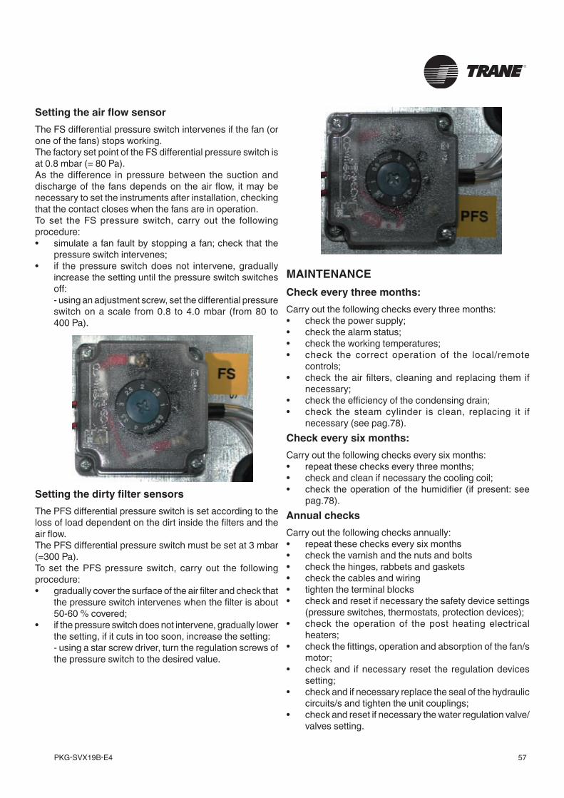
57PKG-SVX19B-E4
Setting the air flow sensorThe FS differential pressure switch intervenes if the fan (or one of the fans) stops working.The factory set point of the FS differential pressure switch is at 0.8 mbar (= 80 Pa).As the difference in pressure between the suction and discharge of the fans depends on the air flow, it may be necessary to set the instruments after installation, checking that the contact closes when the fans are in operation.To set the FS pressure switch, carry out the following procedure:• simulate a fan fault by stopping a fan; check that the
pressure switch intervenes;• if the pressure switch does not intervene, gradually
increase the setting until the pressure switch switches off:
- using an adjustment screw, set the differential pressure switch on a scale from 0.8 to 4.0 mbar (from 80 to 400 Pa).
MAINTENANCECheck every three months:Carry out the following checks every three months:• check the power supply;• check the alarm status;• check the working temperatures;• check the correct operation of the local/remote
controls; • check the air filters, cleaning and replacing them if
necessary;• check the efficiency of the condensing drain; • check the steam cylinder is clean, replacing it if
necessary (see pag.78).Check every six months: Carry out the following checks every six months:• repeat these checks every three months;• check and clean if necessary the cooling coil;• check the operation of the humidifier (if present: see
pag.78).Annual checksCarry out the following checks annually:• repeat these checks every six months• check the varnish and the nuts and bolts• check the hinges, rabbets and gaskets• check the cables and wiring • tighten the terminal blocks• check and reset if necessary the safety device settings
(pressure switches, thermostats, protection devices);• check the operation of the post heating electrical
heaters;• check the fittings, operation and absorption of the fan/s
motor;• check and if necessary reset the regulation devices
setting;• check and if necessary replace the seal of the hydraulic
circuits/s and tighten the unit couplings;• check and reset if necessary the water regulation valve/
valves setting.
Setting the dirty filter sensorsThe PFS differential pressure switch is set according to the loss of load dependent on the dirt inside the filters and the air flow.The PFS differential pressure switch must be set at 3 mbar (=300 Pa).To set the PFS pressure switch, carry out the following procedure:• gradually cover the surface of the air filter and check that
the pressure switch intervenes when the filter is about 50-60 % covered;
• if the pressure switch does not intervene, gradually lower the setting, if it cuts in too soon, increase the setting:
- using a star screw driver, turn the regulation screws of the pressure switch to the desired value.
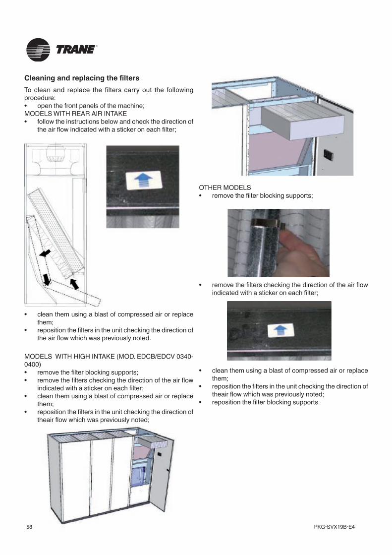
PKG-SVX19B-E458
Cleaning and replacing the filtersTo clean and replace the filters carry out the following procedure:• open the front panels of the machine; MODELS WITH REAR AIR INTAKE• follow the instructions below and check the direction of
the air flow indicated with a sticker on each filter;
• clean them using a blast of compressed air or replace them;
• reposition the filters in the unit checking the direction of the air flow which was previously noted.
MODELS WITH HIGH INTAKE (MOD. EDCB/EDCV 0340-0400)• remove the filter blocking supports;• remove the filters checking the direction of the air flow
indicated with a sticker on each filter;• clean them using a blast of compressed air or replace
them;• reposition the filters in the unit checking the direction of
theair flow which was previously noted;
OTHER MODELS• remove the filter blocking supports;
• remove the filters checking the direction of the air flow indicated with a sticker on each filter;
• clean them using a blast of compressed air or replace them;
• reposition the filters in the unit checking the direction of theair flow which was previously noted;
• reposition the filter blocking supports.
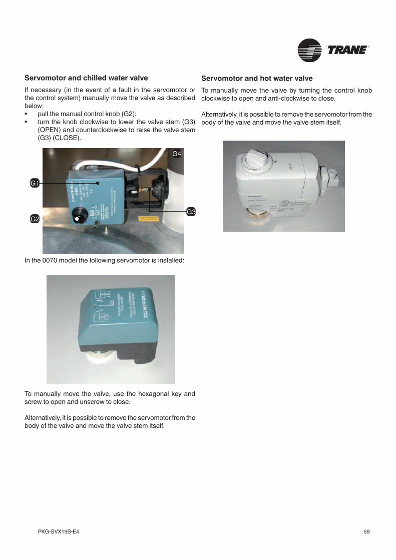
59PKG-SVX19B-E4
Servomotor and chilled water valveIf necessary (in the event of a fault in the servomotor or the control system) manually move the valve as described below:• pull the manual control knob (G2);• turn the knob clockwise to lower the valve stem (G3)
(OPEN) and counterclockwise to raise the valve stem (G3) (CLOSE).
In the 0070 model the following servomotor is installed:
To manually move the valve, use the hexagonal key and screw to open and unscrew to close.
Alternatively, it is possible to remove the servomotor from the body of the valve and move the valve stem itself.
Servomotor and hot water valveTo manually move the valve by turning the control knob clockwise to open and anti-clockwise to close.
Alternatively, it is possible to remove the servomotor from the body of the valve and move the valve stem itself.
G1
G2G3
G4
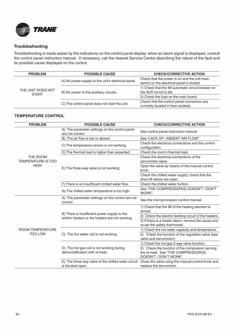
PKG-SVX19B-E460
PROBLEM POSSIBLE CAUSE CHECK/CORRECTIVE ACTION
THE ROOM TEMPERATURE IS TOO
HIGH
A) The parameter settings on the control panel are not correct. See control panel instruction manual
B) The air flow is low or absent. See “LACK OF / ABSENT AIR FLOW”.
C) The temperature sensor is not working. Check the electrical connections and the control configuration.
D) The thermal load is higher than expected. Check the room’s thermal load.
E) The three-way valve is not working.
Check the electrical connections of the servomotor valve. Open the valve by means of the manual control knob. Check the chilled water supply; check that the shut-off valves are open.
F) There is an insufficient chilled water flow. Check the chilled water funtion.
G) The chilled water temperature is too high. See “THE COMPRESSOR(S) DOESN’T / DON’T WORK”.
ROOM TEMPERATURE TOO LOW
A) The parameter settings on the control are not correct See the microprocessor control manual.
B) There is insufficient power supply to the elcttric heaters or the heaters are not working
1) Check that the IM of the heating element is armed.2) Check the electric feeding circuit of the heaters.3) If there is a heater alarm, remove the cause and re-set the safety thermostat.
C) The hot water coil is not working.1) Check the hot water capacity and temperature.2) Check the function of the regulation valve (see valve and servomotor).
D) The hot gas coil is not working during dehumidification with re-heat.
1) Check the hot gas 3 way valve function.2) Check the function of the compressor serving the re-heat. See “THE COMPRESSOR(S) DOESN’T / DON’T WORK”.
E) The three way valve of the chilled water circuit is blocked open.
Close the valve using the manual control knob and replace the servomotor.
PROBLEM POSSIBLE CAUSE CHECK/CORRECTIVE ACTION
THE UNIT DOES NOT START
A) No power supply to the unit’s electrical panel. Check that the power is on and the unit main switch on the electrical panel is closed.
B) No power to the auxiliary circuits.1) Check that the IM automatic circuit breaker on the AUX circuit is set.2) Check the fuse on the main board.
C) The control panel does not start the unit. Check that the control panel connectors are correctly located in their sockets.
TroubleshootingTroubleshooting is made easier by the indications on the control panel display: when an alarm signal is displayed, consult the control panel instruction manual. If necessary, call the nearest Service Centre describing the nature of the fault and its possible cause displayed on the control.
TEMPERATURE CONTROL
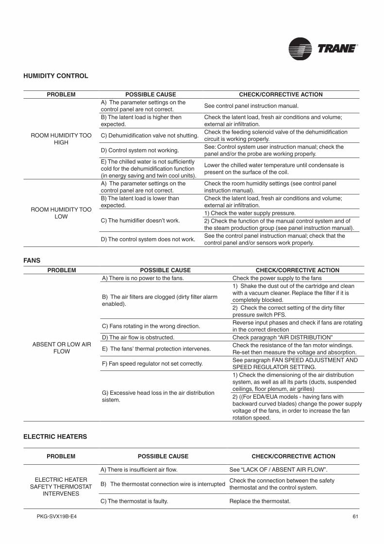
61PKG-SVX19B-E4
PROBLEM POSSIBLE CAUSE CHECK/CORRECTIVE ACTION
ROOM HUMIDITY TOO HIGH
A) The parameter settings on the control panel are not correct. See control panel instruction manual.
B) The latent load is higher then expected.
Check the latent load, fresh air conditions and volume; external air infiltration.
C) Dehumidification valve not shutting. Check the feeding solenoid valve of the dehumidification circuit is working properly.
D) Control system not working. See: Control system user instruction manual; check the panel and/or the probe are working properly.
E) The chilled water is not sufficiently cold for the dehumidification function (in energy saving and twin cool units).
Lower the chilled water temperature until condensate is present on the surface of the coil.
ROOM HUMIDITY TOO LOW
A) The parameter settings on the control panel are not correct.
Check the room humidity settings (see control panel instruction manual).
B) The latent load is lower than expected.
Check the latent load, fresh air conditions and volume; external air infiltration.
C) The humidifier doesn’t work.1) Check the water supply pressure.2) Check the function of the manual control system and of the steam production group (see panel instruction manual).
D) The control system does not work. See the control panel instruction manual; check that the control panel and/or sensors work properly.
PROBLEM POSSIBLE CAUSE CHECK/CORRECTIVE ACTION
ABSENT OR LOW AIR FLOW
A) There is no power to the fans. Check the power supply to the fans
B) The air filters are clogged (dirty filter alarm enabled).
1) Shake the dust out of the cartridge and clean with a vacuum cleaner. Replace the filter if it is completely blocked.2) Check the correct setting of the dirty filter pressure switch PFS.
C) Fans rotating in the wrong direction. Reverse input phases and check if fans are rotating in the correct direction
D) The air flow is obstructed. Check paragraph “AIR DISTRIBUTION”
E) The fans’ thermal protection intervenes. Check the resistance of the fan motor windings. Re-set then measure the voltage and absorption.
F) Fan speed regulator not set correctly. See paragraph FAN SPEED ADJUSTMENT AND SPEED REGULATOR SETTING.
G) Excessive head loss in the air distribution sistem.
1) Check the dimensioning of the air distribution system, as well as all its parts (ducts, suspended ceilings, floor plenum, air grilles)2) ((For EDA/EUA models - having fans with backward curved blades) change the power supply voltage of the fans, in order to increase the fan rotation speed.
PROBLEM POSSIBLE CAUSE CHECK/CORRECTIVE ACTION
ELECTRIC HEATER SAFETY THERMOSTAT
INTERVENES
A) There is insufficient air flow. See “LACK OF / ABSENT AIR FLOW”.
B) The thermostat connection wire is interrupted Check the connection between the safety thermostat and the control system.
C) The thermostat is faulty. Replace the thermostat.
HUMIDITY CONTROL
FANS
ELECTRIC HEATERS
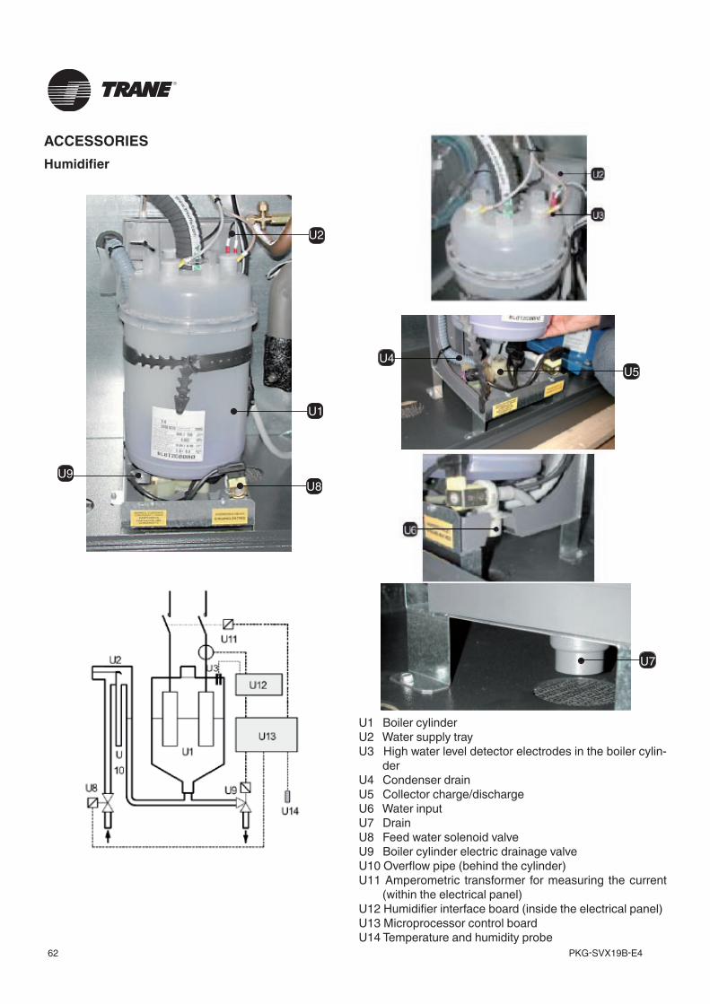
PKG-SVX19B-E462
ACCESSORIESHumidifier
U1 Boiler cylinderU2 Water supply trayU3 High water level detector electrodes in the boiler cylin-
derU4 Condenser drainU5 Collector charge/dischargeU6 Water inputU7 DrainU8 Feed water solenoid valveU9 Boiler cylinder electric drainage valve U10 Overflow pipe (behind the cylinder)U11 Amperometric transformer for measuring the current
(within the electrical panel)U12 Humidifier interface board (inside the electrical panel)U13 Microprocessor control boardU14 Temperature and humidity probe
U7
U4
U9
U5
U1
U8
U2
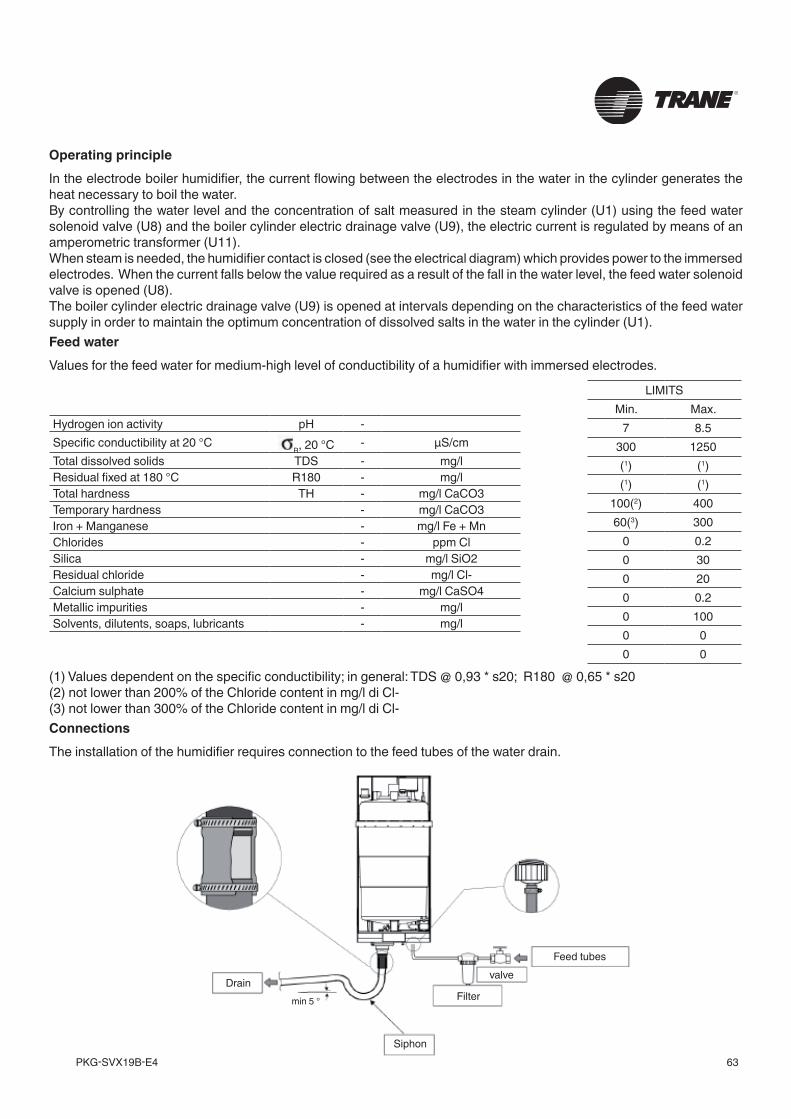
63PKG-SVX19B-E4
Operating principleIn the electrode boiler humidifier, the current flowing between the electrodes in the water in the cylinder generates the heat necessary to boil the water.By controlling the water level and the concentration of salt measured in the steam cylinder (U1) using the feed water solenoid valve (U8) and the boiler cylinder electric drainage valve (U9), the electric current is regulated by means of an amperometric transformer (U11).When steam is needed, the humidifier contact is closed (see the electrical diagram) which provides power to the immersed electrodes. When the current falls below the value required as a result of the fall in the water level, the feed water solenoid valve is opened (U8).The boiler cylinder electric drainage valve (U9) is opened at intervals depending on the characteristics of the feed water supply in order to maintain the optimum concentration of dissolved salts in the water in the cylinder (U1).Feed waterValues for the feed water for medium-high level of conductibility of a humidifier with immersed electrodes.
ConnectionsThe installation of the humidifier requires connection to the feed tubes of the water drain.
(1) Values dependent on the specific conductibility; in general: TDS @ 0,93 * s20; R180 @ 0,65 * s20(2) not lower than 200% of the Chloride content in mg/l di Cl-(3) not lower than 300% of the Chloride content in mg/l di Cl-
Hydrogen ion activity pH -Specific conductibility at 20 °C
R, 20 °C - µS/cmTotal dissolved solids TDS - mg/lResidual fixed at 180 °C R180 - mg/lTotal hardness TH - mg/l CaCO3Temporary hardness - mg/l CaCO3Iron + Manganese - mg/l Fe + MnChlorides - ppm ClSilica - mg/l SiO2Residual chloride - mg/l Cl-Calcium sulphate - mg/l CaSO4Metallic impurities - mg/lSolvents, dilutents, soaps, lubricants - mg/l
LIMITSMin. Max.
7 8.5300 1250(1) (1)(1) (1)
100(2) 40060(3) 300
0 0.20 300 200 0.20 1000 00 0
Siphon
DrainFilter
valveFeed tubes
min 5 °
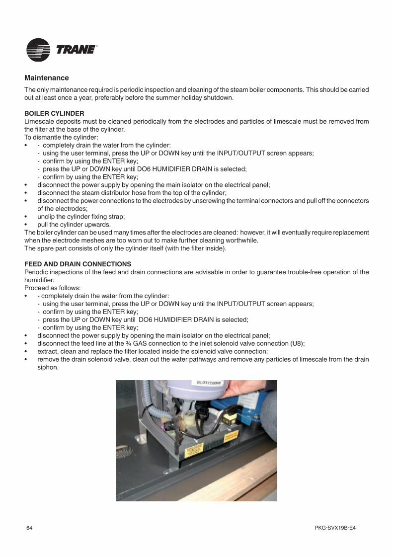
PKG-SVX19B-E464
MaintenanceThe only maintenance required is periodic inspection and cleaning of the steam boiler components. This should be carried out at least once a year, preferably before the summer holiday shutdown.
BOILER CYLINDERLimescale deposits must be cleaned periodically from the electrodes and particles of limescale must be removed from the filter at the base of the cylinder.To dismantle the cylinder:• - completely drain the water from the cylinder: - using the user terminal, press the UP or DOWN key until the INPUT/OUTPUT screen appears; - confirm by using the ENTER key; - press the UP or DOWN key until DO6 HUMIDIFIER DRAIN is selected; - confirm by using the ENTER key;• disconnect the power supply by opening the main isolator on the electrical panel;• disconnect the steam distributor hose from the top of the cylinder;• disconnect the power connections to the electrodes by unscrewing the terminal connectors and pull off the connectors
of the electrodes;• unclip the cylinder fixing strap;• pull the cylinder upwards.The boiler cylinder can be used many times after the electrodes are cleaned: however, it will eventually require replacement when the electrode meshes are too worn out to make further cleaning worthwhile.The spare part consists of only the cylinder itself (with the filter inside).
FEED AND DRAIN CONNECTIONSPeriodic inspections of the feed and drain connections are advisable in order to guarantee trouble-free operation of the humidifier.Proceed as follows:• - completely drain the water from the cylinder: - using the user terminal, press the UP or DOWN key until the INPUT/OUTPUT screen appears; - confirm by using the ENTER key; - press the UP or DOWN key until DO6 HUMIDIFIER DRAIN is selected; - confirm by using the ENTER key;• disconnect the power supply by opening the main isolator on the electrical panel;• disconnect the feed line at the ¾ GAS connection to the inlet solenoid valve connection (U8);• extract, clean and replace the filter located inside the solenoid valve connection;• remove the drain solenoid valve, clean out the water pathways and remove any particles of limescale from the drain
siphon.
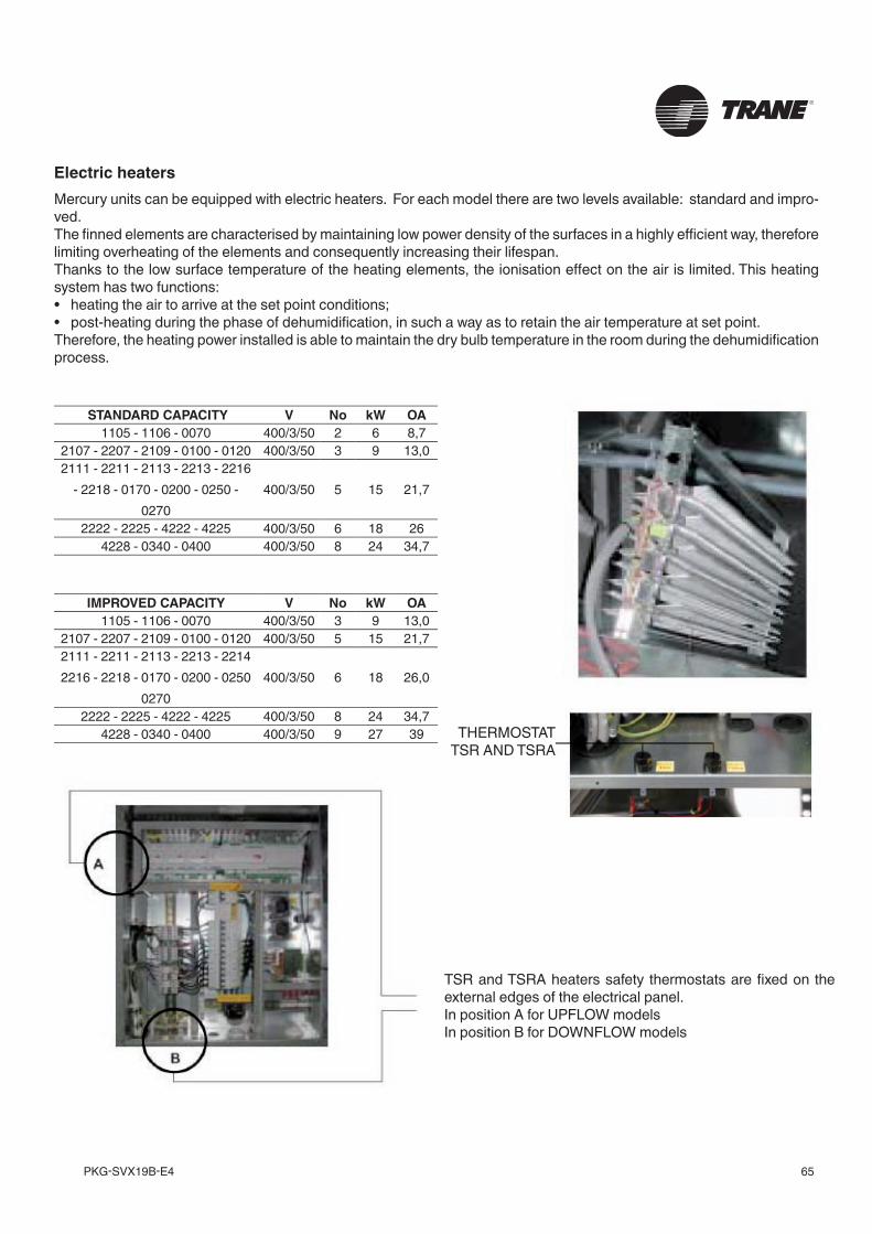
65PKG-SVX19B-E4
Electric heatersMercury units can be equipped with electric heaters. For each model there are two levels available: standard and impro-ved.The fi nned elements are characterised by maintaining low power density of the surfaces in a highly effi cient way, therefore limiting overheating of the elements and consequently increasing their lifespan.Thanks to the low surface temperature of the heating elements, the ionisation eff ect on the air is limited. This heating system has two functions:• heating the air to arrive at the set point conditions;• post-heating during the phase of dehumidifi cation, in such a way as to retain the air temperature at set point.Therefore, the heating power installed is able to maintain the dry bulb temperature in the room during the dehumidifi cation process.
TSR and TSRA heaters safety thermostats are fi xed on the external edges of the electrical panel.In position A for UPFLOW modelsIn position B for DOWNFLOW models
STANDARD CAPACITY V No kW OA1105 - 1106 - 0070 400/3/50 2 6 8,7
2107 - 2207 - 2109 - 0100 - 0120 400/3/50 3 9 13,02111 - 2211 - 2113 - 2213 - 2216
- 2218 - 0170 - 0200 - 0250 - 0270
400/3/50 5 15 21,7
2222 - 2225 - 4222 - 4225 400/3/50 6 18 264228 - 0340 - 0400 400/3/50 8 24 34,7
IMPROVED CAPACITY V No kW OA1105 - 1106 - 0070 400/3/50 3 9 13,0
2107 - 2207 - 2109 - 0100 - 0120 400/3/50 5 15 21,72111 - 2211 - 2113 - 2213 - 2214 2216 - 2218 - 0170 - 0200 - 0250
0270400/3/50 6 18 26,0
2222 - 2225 - 4222 - 4225 400/3/50 8 24 34,74228 - 0340 - 0400 400/3/50 9 27 39 THERMOSTAT
TSR AND TSRA
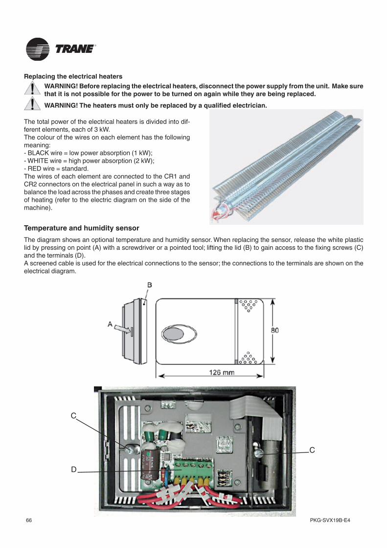
PKG-SVX19B-E466
Replacing the electrical heatersWARNING! Before replacing the electrical heaters, disconnect the power supply from the unit. Make sure that it is not possible for the power to be turned on again while they are being replaced.WARNING! The heaters must only be replaced by a qualified electrician.
The total power of the electrical heaters is divided into dif-ferent elements, each of 3 kW.The colour of the wires on each element has the following meaning:- BLACK wire = low power absorption (1 kW);- WHITE wire = high power absorption (2 kW);- RED wire = standard.The wires of each element are connected to the CR1 and CR2 connectors on the electrical panel in such a way as to balance the load across the phases and create three stages of heating (refer to the electric diagram on the side of the machine).
Temperature and humidity sensorThe diagram shows an optional temperature and humidity sensor. When replacing the sensor, release the white plastic lid by pressing on point (A) with a screwdriver or a pointed tool; lifting the lid (B) to gain access to the fixing screws (C) and the terminals (D).A screened cable is used for the electrical connections to the sensor; the connections to the terminals are shown on the electrical diagram.
D
C
C
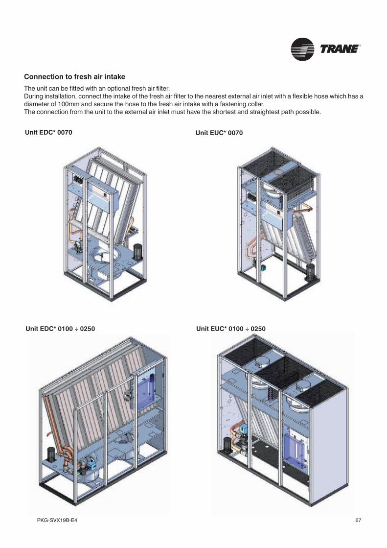
67PKG-SVX19B-E4
Connection to fresh air intakeThe unit can be fitted with an optional fresh air filter. During installation, connect the intake of the fresh air filter to the nearest external air inlet with a flexible hose which has a diameter of 100mm and secure the hose to the fresh air intake with a fastening collar.The connection from the unit to the external air inlet must have the shortest and straightest path possible.
Unit EDC* 0070 Unit EUC* 0070
Unit EDC* 0100 ÷ 0250 Unit EUC* 0100 ÷ 0250
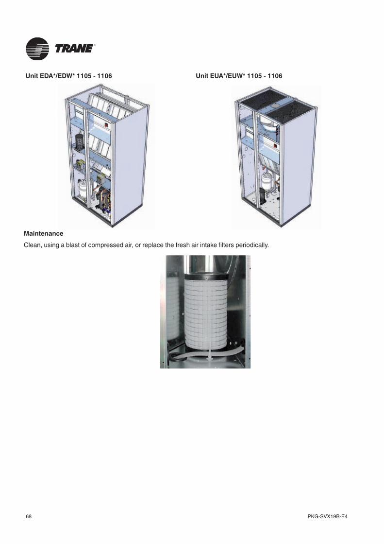
PKG-SVX19B-E468
MaintenanceClean, using a blast of compressed air, or replace the fresh air intake filters periodically.
Unit EDA*/EDW* 1105 - 1106 Unit EUA*/EUW* 1105 - 1106
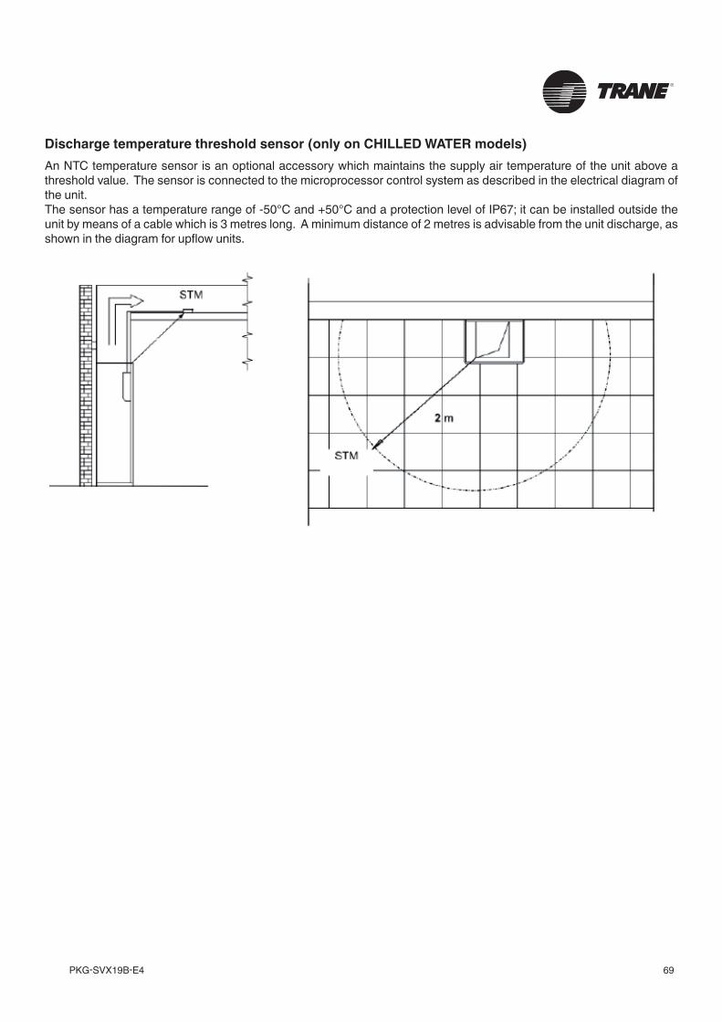
69PKG-SVX19B-E4
Discharge temperature threshold sensor (only on CHILLED WATER models)An NTC temperature sensor is an optional accessory which maintains the supply air temperature of the unit above a threshold value. The sensor is connected to the microprocessor control system as described in the electrical diagram of the unit.The sensor has a temperature range of -50°C and +50°C and a protection level of IP67; it can be installed outside the unit by means of a cable which is 3 metres long. A minimum distance of 2 metres is advisable from the unit discharge, as shown in the diagram for upflow units.
PKG-SVX19B-E470
71PKG-SVX19B-E4
Trane optimizes the performance of homes and buildings around the world. A business of Ingersoll Rand, the leader in creating and sustaining safe, comfortable and energy efficient environments, Trane offers a broad portfolio of advanced controls and HVAC systems, comprehensive building services, and parts. For more information, visit www.Trane.com.
Trane has a policy of continuous product and product data improvement and reserves the right to change design and specifications without notice.
© 2012 Trane All rights reserved PKG-SVX19B-E4 April 2012
We are committed to using environmentally conscious print practices that reduce waste.


![Wp edWb[ Yllgda[aÛ...3IOFFRIRÌUN5OVODI 0ASQUAACHIDARÌUN CONTRIBUTOMINIMODI % FRQLOSDWURFLQLRGL 6XD(FFHOOHQ]D 0RQV ,JQD]LR=DPELWR 9HVFRYRGHOOD'LRFHVLGL3DWWL DISTRIBUZIONEDI 5OVADI](https://img.pdfslide.net/doc/110x75/5fa662c10dfcc335b439d0eb/wp-edwb-yllgdaa-3ioffriroeun5ovodi-0asquaachidaroeun-contributominimodi.jpg)

![I ij[cWi dWY edWb[i Z[ Y [dY W j[Ydebe] W [ ddelWY d [d 7c](https://img.pdfslide.net/doc/110x75/619b03ad84e9401365792849/i-ijcwi-dwy-edwbi-z-y-dy-w-jydebe-w-ddelwy-d-d-7c-.jpg)