Embed Size (px)
Citation preview

Overview The TwinCAT System Manager is the central configuration tool of the TwinCAT System. It is where the inputs and outputs of the software tasks and the physical inputs and outputs of the connected fieldbusses are managed. The individual software tasks (e.g. PLC tasks) each operate on their own private process image so that the addresses of the symbols mapped in the process image (variables) are relevant and valid only within that particular task.
The I/O information of the individual Software Tasks is read from and entered in the TwinCAT System Manager. From there, the installed fieldbusses and their connected modules/boxes are also described. The logical and physical inputs and outputs are assigned to one another by linking software task variables and fieldbus variables.
Task-task communication:
With the aid of the TwinCAT System Manager, the ”in and outputs” of a task can be cyclically exchanged with the ”out and inputs” of another task. The data consistency remains thereby intact.
Variable orientated:
The smallest addressable and linkable unit is a variable. Variables can be individual bits, bytes, 16 bit data words, 32 bit data words etc. Variables can also be structures or arrays (fields) consisting of other data types.
Process Images:
Variables are always precisely assigned to a process image, i.e. the address of the variable is indicated unambiguously in its process image - but only within that process image. Each software task and each fieldbus possesses precisely one process image (exception: PLC run time system tasks share a combined process image).
Assignments:
The TwinCAT System Manager produces individual assignments which contain the links created. Assignments are produced between software tasks and fieldbus devices and between software tasks if these have mutually linked variables. I.e. if a PLC task variable is linked to the variables of a fieldbus an assignment will be produced between these two. If the same PLC task has other variables linked with another fieldbus, a second assignment will be generated. The assignments contain the corresponding copying directives in order to enable the exchange of the corresponding variables at the run time.
Fieldbus independence :
When defining and programming the software tasks participating in the TwinCAT system it is not necessary to know the type and structure of these or the fieldbus used. Programming is carried out with the aid of logical variables which are defined locally within the software itself. The TwinCAT System Manager links these logical variables with other variables, which correspond either to physical inputs and outputs on the fieldbus or to logical variables of other tasks. The type and the special properties of each fieldbus do not need to be known or taken into account.
TwinCAT System Manager supports all standard commercial fieldbusses and some other PC standard interfaces:
� Beckhoff Lightbus � Profibus DP, MC (DP-V2) � Interbus � CANopen � SERCOS � DeviceNet � Ethernet � Beckhoff Real-Time Ethernet � PC printer port (8 inputs and 8 outputs on TTL basis) � Serial Bus Coupler BK8100 to COM � USB Bus Coupler BK9500 and USB Control Panel interface (CPx8xx) � Dual-ported memory interface (DPRAM) for PC cards � NOVRAM (Non-Volatile RAM) � System Management Bus (SMB) for monitoring of PC hardware like fans, temperatures, etc...
Detailed information on the various fieldbus cards and other supported I/O devices can be found in our Reference Documentation.
Starting TwinCAT System Manager:
To open the TwinCAT System Manager, move the mouse to the Windows 'start' menu and select 'start' -> 'Programs' -> TwinCAT System' -> ' TwinCAT System Manager' or start it from the Windows SysTray by clicking the TwinCAT icon and selecting 'System Manager' from the appearing Pop-up menu as shown below:
TwinCAT System Manager
Page 1 of 390Overview
8/7/2006file://C:\Documents and Settings\tope\Local Settings\Temp\~hhD469.htm

System Manager components :
The System Manager window is structured as shown in the image below (up to TwinCAT version 2.8):
The project name is written in the title bar (upper blue bar), in this case Machine.wsm. The menu bar and the toolbar (symbol bar) are below the title bar. There functions are described in the following chapter Operation.
In the large left-hand window a tree structure is displayed which contains all system configuration components.
At the bottom you can see the status line which provides information on the current system status. In the below case the system is running, this is indicated by the word ”RTime”.
For a description of the System Manager main window from TwinCAT version 2.9, please refer to: TwinCAT System Manager -> Introduction.
System configuration model of the TwinCAT System Manager
The list below gives the various main components of the TwinCAT System Manager. The existence of the configuration components depends upon the Level of the Installed TwinCAT System.
Configuration module Description
Real Time - Configuration Basic system settings are carried out. The basis time for the system is specified. User-defined tasks can also be integrated.Up to four PLC programs can be integrated into the maximum four run-time systems. Up to four tasks
Page 2 of 390Overview
8/7/2006file://C:\Documents and Settings\tope\Local Settings\Temp\~hhD469.htm

Further information on the use of the TwinCAT System Manager can be found in the TwinCAT Quick Start documentation.
Introduction On the picture below, the main window of the TwinCAT System Manager (v2.9) is shown. Hyperlinks to the respective descriptions of the different elements of this main window are listed in the table underneath.
The field with the red background in the lower right part of the main window signals that the System Manager is currently logged into a remote system. The text in this field names the remote system (in the example this is a target with the TwinCAT Router name 'CX Headless' and the AmsNetId '1.1.1.1.1.1'). A double-click on this field opens the "Choose Target System" dialog. Furthermore, the actual remote system name is displayed in the titlebar of the main window. If the field in the lower right corner is just grey as the rest of the window frame, it means that the System Manager is logged into a local target system.
The field with the blue background signals that the remote system is currently in "Config Mode". It can also turn into green ("Running") or yellow (connection establishment / Timeout). Independently, the local system can always be in a different mode (see TwinCAT System Control icon color in SysTray of the local machine). In reference to the above picture, it could currently be in "Running" mode for example.
PLC - Configuration per run-time system can be carried out and the links between the individual task and the variables is configured.
Cam - Configuration The optional electronic camshaft controller is configured.I/O - Configuration All devices and fieldbus components are listed and configured. These include:
� all fieldbus cards, the boxes (beneath those fieldbus cards) and terminals connected to the boxes. � the uninterrupted power supply (serial or 24V) � serial and parallel interfaces � Motherboard diagnosis interfaces (SMB).
TwinCAT System Manager: Introduction
Informations about DescriptionMenues and Buttons The main menues and Toolbar of the TwinCAT System ManagerSYSTEM -Configuration System configuration and Real-Time settings of the local resp. remote system
NC - Configuration Configuration of TwinCAT - NC / NCI (minimum level "TwinCAT NC")
Page 3 of 390Overview
8/7/2006file://C:\Documents and Settings\tope\Local Settings\Temp\~hhD469.htm

Main Menus The control elements, more precisely the menu bar and the toolbar of the TwinCAT System Manager are described below. Some menu items and buttons were added with TwinCAT 2.8 and 2.9.
The menu bar comprises the following six options:
File, Edit, Actions, View, Options and ? (Help).
Where present, the toolbar icons are displayed next to their corresponding menu item.
The name of the currently active TwinCAT System Manager project is displayed in the header (or as "Untitled", if a new project has not yet been saved with a name).
The normal Windows control elements also appear in the right-hand corner of the title bar:
Moves the System Manager to the task bar without closing the project
/ Minimizes resp. maximizes the System Manager window.
Exits / closes the TwinCAT System Manager application.
Note:
As the TwinCAT System Manager is context-sensitive, not all menu items are active at all times!
”File” menu
PLC - Configuration Configuration of TwinCAT System Manager relevant PLC settings (minimum level "TwinCAT PLC") Cam - Configuration Configuration of the (optional) TwinCAT Cam Server I/O - Configuration Configurations for the I/O part on the local resp. remote target system
I/O Devices At local or remote target system configured Input and Output devices (Fieldbus cards, NOVRAM, system interfaces,..) and their process images
Mappings IInformations about mappings between the I/O devices and other TwinCAT devices, resp. their process images
TwinCAT System Manager: Controls
Page 4 of 390Overview
8/7/2006file://C:\Documents and Settings\tope\Local Settings\Temp\~hhD469.htm

New
Creates a new System Manager project (blank configuration).
Open
Opens a dialogue for the selection of an existing saved System Manager project.
Open Currently Active
Opens the project file whose configuration is currently active in the TwinCAT system.
Save
Saves the current configuration in a TwinCAT System Manager *.wsm file (respectively *.tsm file under TwinCAT 2.9).
Save As
Saves the current configuration in a *.wsm file with user-defined name and location.
Hint:
At TwinCAT version 2.9, a new file format (Structured Storage) was implemented for saving of TwinCAT System Manager configurations. This new file format gets the file extension *.tsm.Alternatively, also under TwinCAT 2.9, configurations can be opened from WSM-files or saved into files with *.wsm extension. To achieve this, the appropriate extension is to be selected at "Save as type:" in the "Save As.." dialog.
Enable Compression
To be lenient with the limited resources on devices of the CX1000 and BXxxxx classes, an optional compression feature for saving of *.tsm configurations has been implemented at TwinCAT 2.9. "Enable Compression" is activated by default and achieves, depending on the project, a space saving of 80% and more.
Properties
Under this new menu item at TwinCAT 2.9, extended document information regarding the System Manager project can be found and edited.
Opens Printing dialog if high-lighted. Printable section required.
Print Preview
Presents view of the selected window which is prepared for printing (depending upon selected area of the System Manager).
Printer Set-up
Opens the printer settings dialogue box.
Exit
Closes the TwinCAT System Manager.
Page 5 of 390Overview
8/7/2006file://C:\Documents and Settings\tope\Local Settings\Temp\~hhD469.htm

”Edit” menu
Undo
Reverses the last action.
Cut
Copies selected object to the clipboard and removes it from the current configuration.
Copy
Copies selected object to the clipboard.
Paste
Inserts elements from the clipboard to the current position.
Paste with Links
Inserts elements with present variable links from the clipboard into the current position.
Note:
Not all functions are available at all times.
”Actions” menu
Generate Mappings
Creates assignment between two process images.
Check Configuration
Checks the current configuration for plausibility.
Activate Configuration
Page 6 of 390Overview
8/7/2006file://C:\Documents and Settings\tope\Local Settings\Temp\~hhD469.htm

This menu item, until TwinCAT v2.8 known as "Save to Registry" where this function saved the configuration indeed into the Windows Registry, saves the current configuration into a XML file which is located under \TwinCAT\Boot and has the file name "CurrentConfig.xml". Pressing this button initiates the saving of the file and activates the configuration by a TwinCAT system (re)start. This function can be also executed from the Command Line without opening the System Manager.
Set/Reset TwinCAT to Run Mode
Starts/restarts the local TwinCAT system with the currently activated configuration (see also: "Activate Configuration"). During this procedure, an eventually configured PLC Bootproject is loaded and started if the necessary "Auto Boot" box is checked (see also: TwinCAT System -> User Interface ->TwinCAT System Control ). This functionality is also available through the Command Line interface without opening the System Manager.
Set/Reset TwinCAT to Config Mode
Starts/restarts the remote TwinCAT configuration. This functionality is needed e.g. for the configuration of the Beckhoff CX1000 series because this type of devices has usually no local TwinCAT System Manager tool for configuration (see also: "Choose Target System").
Reload Devices
Rescans the I/O configuration at the selected target system and displays it in the System Manager tree view.
Choose Target System
With this item you can select the appropriate target system, where the configuration has to be made for (see also: "Set/Reset TwinCAT to Config Mode").
Read Target Server Versions
Reads the current TwinCAT server versions available on the prior selected target system.
Update Bus Coupler/IP Link Firmware
Updates the Firmware of Beckhoff Bus Couplers or Fieldbus Boxes through serial COM port.
Access Bus Coupler/IP Link Register
The user can access any available register at a Bus Coupler or Fieldbus Box module via COM port or TCP/IP address after entering the necessary information in the upcoming dialog.
Export XML Description
Saves the configuration data of the currently highlighted tree item as a XML Description file to disk.
Import XML Description
Imports the configuration data of a previously saved XML Description file into the current System Manager configuration.
Check Variable Links
Validates the current mapping information.
”View” menu
Toolbar
Displays or hides the tool bar.
Status Bar
Page 7 of 390Overview
8/7/2006file://C:\Documents and Settings\tope\Local Settings\Temp\~hhD469.htm

Displays or hides the status bar. The status bar is displayed at the lower edge of the main window.
Split
Activates a movement off a dividing line between the tree view and the dialogues in the System Manager main window.
Show Logger Output
Displays or removes the Logger Window at the lower edge of the System Manager.
Show Watch Window
Displays/removes the Watch Window within the System Manager.
Show Current Real Time Capacity
Displays/removes the real time load of the (starting) TwinCAT system in the lower right-hand corner of the main window.
Show Online Data
Displays/removes the online data of the configured variables. The current configuration for a display must be active, i.e. saved, in the registry and the TwinCAT system must be started.
Show Sub Variables
Displays the sub-variables of variables.
Show Expert Mode
Displays or removes seldom used parameters for various settings dialogues in the System Manager.
”Options” menu
Language
Opens the selection menu to select one of the languages of the country supported by the TwinCAT System Manager.
Check PLC Project Changes
If this option is selected, a message box appears when saving configuration changes to PLC projects. This message box requests the PLC Configuration to be re-loaded in.
Open Logger Automatically
Automatically opens the Logger Window when System Manager is started and displays current TwinCAT events.
Open last Used File
Automatically opens the last saved *.wsm file when System Manager is started.
Page 8 of 390Overview
8/7/2006file://C:\Documents and Settings\tope\Local Settings\Temp\~hhD469.htm

Select Last Tree Element
Automatically opens the last saved display of the configuration tree.
Generate BAK-File
When this option is selected a ”Current Name”.bak file is created as a backup file with each saving.
Auto Save to Target
When this option is selected, additionally to the local system the configuration is also saved to the target system (e.g. when configuring a CX1000 or BXxxxx). By default, the configuration is saved in a zipped version. See also: "Enable Compression".
Show Real-Time Ethernet Compatible Devices
See: Reference | "Ethernet Miniport (Real-Time)"
Change PCMCIA Base Address
Opens settings dialogue to change the PC Card base address. After making changes it is necessary to restart Windows.
”Help” menu (?)
Help Topics
Opens the TwinCAT System Manager Help files. Help is a part of the TwinCAT Information System. If you require an English version of Help, you need to install the English language TwinCAT Information System.
Help Context
When the TwinCAT Information System is installed, opens the Help page relating to the area selected in the System Manager.
About TwinCAT System Manager
Calls up information about the current installed version of the TwinCAT System Manager.
Other buttons on the tool bar:
Find
Opens device search dialog within the System Manager.
Search Devices
If in the System Manager TreeView on the left-hand side "I/O Devices" (below I/O - Configuration) is marked, with this button a device scan procedure is started. It starts with searching available I/O devices and, if those are found, continuous with attached "boxes" and - if applicable - Bus Terminals or IP-Link extension modules.
Hint:
TwinCAT 2.9 is necessary for this feature and the target system has to be in "Config Mode" to search for devices (the current mode is shown in the lower right corner of the System Manager Main Window).
Toggle Free Run State
After enabling this button, and if the target system is currently in Config Mode, found I/O devices can be set to Free-Run mode. Means, e.g. I/O channels of Bus Terminals can be set (written) to a certain status without having any PLC project or other triggering task active.
Hint:
Page 9 of 390Overview
8/7/2006file://C:\Documents and Settings\tope\Local Settings\Temp\~hhD469.htm

If the target system has been in Run-Mode before, "Reload Devices" has to be executed once before the I/o drivers for the device can be set to Free-Run state.
Full expand tree below selected item
After pushing this button, the entry marked in the TreeView will be shown in the fully expanded view.
Definition Remote- resp. Target System ...
Access Rights on "Remote-PC"
...
Choose Target System Under preparation...
Add Route Dialog The list of target systems or remote systems that can be reached can be extended with the aid of the following dialog:
TwinCAT System Manager: System Configuration
TwinCAT System Manager: Controls
TwinCAT System Manager: System Configuration
Page 10 of 390Overview
8/7/2006file://C:\Documents and Settings\tope\Local Settings\Temp\~hhD469.htm

Enter Host Name / IP
Executes the 'GetHostByName' command. The effect of this is that the name entered here is searched for in the network (subnet) as a possible TwinCAT target system or remote system.
Broadcast Search
Looks for all the TwinCAT systems connected to the current subnet. In order for the System Manager to find the targets, TwinCAT here must either be in config mode or in run mode.
Host Name
The name of the remote or target system in the network.
Connected
Indicates the status of the connection.
Address
Specifies the address of the device concerned. The nature of the address depends on the transport protocol being used. If this is 'TCP/IP', it is therefore the TCP/IP address.
AMS NetId
The identification address of the device for the TwinCAT Router. See: ADS-AmsNetId.
TwinCAT
Gives the versions and build numbers of the TwinCAT target system.
OS Version
Indicates the operating system installed at the target.
Route Name [Target], AmsNetId, Transport Type
Repeats this data in the relevant column when a target is chosen from the list.
Address Info
See Host Name and/or IP Address.
- Host Name
The Address Info is the name of the target.
Page 11 of 390Overview
8/7/2006file://C:\Documents and Settings\tope\Local Settings\Temp\~hhD469.htm
- IP Address
The Address Info is the IP address of the target.
Add Route
Add the chosen target to the "routes".
Route Name (Remote)
...
The "Logon Information" dialog
It is necessary to have been assigned the required rights in order to be able to configure a remote or target system. If this has not been done, the following dialog appears:
If you have the password and user name for the required user group, they can be entered here, and the ability to configure the system is then granted. It is then possible to choose the system as a target from the "Selection of the target system.." menu. This does, however, only work when the configuration computer being used is also entered at the target system as a TwinCAT router device.
The System Manager in Config Mode Under preparation...
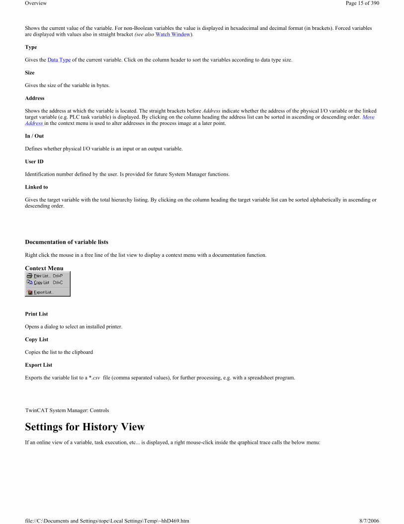
Watch Window When the Watch Window display is selected, the following window appears at the lower edge of the System Manager (shown here with sample variables):
TwinCAT System Manager: Controls
TwinCAT System Manager: Controls
Page 12 of 390Overview
8/7/2006file://C:\Documents and Settings\tope\Local Settings\Temp\~hhD469.htm

Variable
Gives the name of the variable being viewed. The arrow symbol indicates whether the variable is linked or not.
Online
Shows the current value of the variable. For non-Boolean variables the value is displayed in hexadecimal and decimal format (in brackets). Forced variables are displayed with values also in straight bracket.
Source
Provides the source of the variable. The information is comprised of ”Variable Name, In or Output, Task Name, PLC Project Name”.
Watchlist Context Menu
A right-hand mouse click in an empty line of the Watch window will display the context menu.
Clear
Removes the variable from Watch window.
Open
Opens previously created and saved Watch window configurations.
Save
Calls up the dialogue to save the Watch window configuration to (file suffix: *.tcw).
Close
Removes the Watch window from the current System Manager view. The configuration is retained, however, and can be recalled at any time using the Menu:View / Show Watch Window.
Logger View When the Logger View is activated the following window appears in the lower section of the System Manager (shown here with some example messages):
Server
Gives the name and the port number of the server which generated the message. An icon is also shown indicating the severity of the error (e.g. System Stopped, etc..).
Timestamp
TwinCAT System Manager: Controls
Page 13 of 390Overview
8/7/2006file://C:\Documents and Settings\tope\Local Settings\Temp\~hhD469.htm

Gives the date and time of the current error message.
Message
Gives a brief description of the error which has occurred.
Logger View - Context Menu
A right-hand mouse click in the Logger window will display its context menu.
Clear
Removes all messages from the Logger output
Filter
Currently in development.
Close
Removes the Logger window from the current System Manager view. The configuration is retained for the duration of the session and can be recalled at any time via the menu using View.. / Show Logger Output.
Status Display In/Outputs When selecting the inputs / outputs entries in the tree view of the System Manager, a list view appears on the right-hand side of the input/output variables for that task (example shows inputs). If you have selected a process image in the tree view, inputs and outputs appear in the list view.
Name
Gives the name of the physical I/O variables. A small arrow in the symbol indicates (exactly like the X in the following column) that the variable is linked. By clicking on the column heading the variable list can be sorted alphabetically in ascending or descending order.
Online
TwinCAT System Manager: Controls
Page 14 of 390Overview
8/7/2006file://C:\Documents and Settings\tope\Local Settings\Temp\~hhD469.htm
Shows the current value of the variable. For non-Boolean variables the value is displayed in hexadecimal and decimal format (in brackets). Forced variables are displayed with values also in straight bracket (see also Watch Window).
Type
Gives the Data Type of the current variable. Click on the column header to sort the variables according to data type size.
Size
Gives the size of the variable in bytes.
Address
Shows the address at which the variable is located. The straight brackets before Address indicate whether the address of the physical I/O variable or the linked target variable (e.g. PLC task variable) is displayed. By clicking on the column heading the address list can be sorted in ascending or descending order. Move Address in the context menu is used to alter addresses in the process image at a later point.
In / Out
Defines whether physical I/O variable is an input or an output variable.
User ID
Identification number defined by the user. Is provided for future System Manager functions.
Linked to
Gives the target variable with the total hierarchy listing. By clicking on the column heading the target variable list can be sorted alphabetically in ascending or descending order.
Documentation of variable lists
Right click the mouse in a free line of the list view to display a context menu with a documentation function.
Context Menu
Print List
Opens a dialog to select an installed printer.
Copy List
Copies the list to the clipboard
Export List
Exports the variable list to a *.csv file (comma separated values), for further processing, e.g. with a spreadsheet program.
Settings for History View If an online view of a variable, task execution, etc... is displayed, a right mouse-click inside the qraphical trace calls the below menu:
TwinCAT System Manager: Controls
Page 15 of 390Overview
8/7/2006file://C:\Documents and Settings\tope\Local Settings\Temp\~hhD469.htm

Stop
With activated Stop command (marked as checked in this case), this otherwise continuously running history view is stopped.
Settings
Opens the below described dialog for the settings related to the online history trace view.
"History Settings" dialog
After a click on Settings..., the following dialog appears:
Maximum
This, thru the right UpDown keys or direct input adjustable field, defiines the maximum value for the history trace view. That means the value, if the trace hits the upper edge of the grid.
MInimum
Defines the minimum value, means the value if the deflection touches the lower edge of the grid.
Grid X
Defines the grid scaling of the trace view in the horizontal range (time axis). The default value here is '10'.
Grid Y
Defines the grid scaling of the trace view in the vertical range as follows: Maximum / Grid Y = number of vertical fields. Example: A Maximum value of '100000' and a Grid Y value of '20000' results in 5 displayed fields on the Y-axis.
Velocity
The feed forward velocity of the trace can be adjusted here. Default velocity is '2'.
OK
Accepts the made changes and closes the History Settings dialog.
Cancel
Disregards eventually made changes and closes the dialog.
Document Properties Dialog TwinCAT System Manager: Controls
Page 16 of 390Overview
8/7/2006file://C:\Documents and Settings\tope\Local Settings\Temp\~hhD469.htm
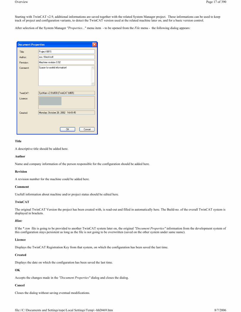
Starting with TwinCAT v2.9, additional informations are saved together with the related System Manager project. These informations can be used to keep track of project and configuration variants, to detect the TwinCAT version used at the related machine later on, and for a basic version control.
After selection of the System Manager "Properties..." menu item - to be opened from the File menu - the following dialog appears:
Title
A descriptive title should be added here.
Author
Name and company information of the person responsible for the configuration should be added here.
Revision
A revision number for the machine could be added here.
Comment
Usefull information about machine and/or project status should be edited here.
TwinCAT
The original TwinCAT Version the project has been created with, is read-out and filled in automatically here. The Build-no. of the overall TwinCAT system is displayed in brackets.
Hint:
If the *.tsm file is going to be provided to another TwinCAT system later on, the original "Document Properties" information from the development system of this configuration stays persistent as long as the file is not going to be overwritten (saved on the other system under same name).
Licence
Displays the TwinCAT Registration Key from that system, on which the configuration has been saved the last time.
Created
Displays the date on which the configuration has been saved the last time.
OK
Accepts the changes made in the "Document Properties" dialog and closes the dialog.
Cancel
Closes the dialog without saving eventual modifications.
Page 17 of 390Overview
8/7/2006file://C:\Documents and Settings\tope\Local Settings\Temp\~hhD469.htm

ToolTip display for System Manager files in Windows Explorer
The "Document Properties" information at *.tsm files described above are conform to the ToolTips feature, established in MS Windows. Therefore, they are going to be displayed during a mouse-over movement on the file name inside the Windows Explorer. The example given below, shows the informations which are going to be displayed in that case:
"Summary" tab at Windows Explorer
Additionaly, the above named informations can be called via Windows Explorer by right-klick on the file and selection of Properties.... Due to tha fact that *.tsm files are in Structured Storage format, you can see most of the "Document Properties" on the below shown "Summary" tab, even if TwinCAT is not installed on the system you are currently at.
Operating Options from the Command Lines When automatically installing an application program including the application-specific TwinCAT files, it is also desirable to automatically activate the
TwinCAT System Manager: Controls
Page 18 of 390Overview
8/7/2006file://C:\Documents and Settings\tope\Local Settings\Temp\~hhD469.htm

System Manager configuration and to automatically start the TwinCAT system.
Command Line Usage
Specify complete TwinCAT System Manager EXE path, the *.wsm file name and path plus the switches described below on the command line and it will execute the following functions:
Supported switches:
/SaveToRegistry
/StartTwinCAT
Further details about commands are given under Control Elements - Main Menus.
Syntax:
TCatSysManager.exe [WSM Path [/SaveToRegistry [/StartTwinCAT]]]
Example 1:
F:\TwinCAT\IO\TCatSysManager.exe Test1.wsm /SaveToRegistry
The System Manager configuration Test1 should be loaded via the command line.
Example 2:
F:\TwinCAT\IO\TCatSysManager.exe Test1.wsm /SaveToRegistry /StartTwinCAT
The System Manager configuration Test1 should be loaded via the command line and the TwinCAT system started or respectively restarted.
Configuration of Variables In and output variables can be added to process images. These can then be linked with the various I/O devices or variables of other tasks. This section explains how to manipulate variables (HI / LO Swap, Force,..).
Add Variables
Variables assigned to the task process image can be added under the menu Inputs and Outputs sub-options.
Note: Variables for PLC tasks cannot be added inside the System Manager. These variables have to be declared within the PLC project using TwinCAT PLC Control (via defined PLC process image address or %Q* resp. %I*) and then added to the System Manager configuration using ReScan... PLC project command. If you go to Tasks, Inputs / Outputs a right mouse click will display the following context menu:
TwinCAT System Manager: I/O Variables
Page 19 of 390Overview
8/7/2006file://C:\Documents and Settings\tope\Local Settings\Temp\~hhD469.htm

Context menu:
Recalc Addresses
Recalculates the addresses of the variables in the process image.
Insert Variable
Displays the following dialogue:
Name
Defines the name of the variable.
Comment
Defines an optional comment on the new variable.
Start Address
Specifies the address of the variable in the task’s process image. This address must be the same as the address at which the task is waiting for the corresponding variable. The variable address can be subsequently changed using Move Address.
Multiple
Multiple variables of the same type can be created and added with sequential addresses.
Variable Type
Lists all currently recognised data types in TwinCAT System Manager from which the type of the new variable(s) can be selected.
Sort by
Allows the list of variable types to be sorted accordingly.
Note:
Adding new variables automatically adapts the size of the task process image.
Page 20 of 390Overview
8/7/2006file://C:\Documents and Settings\tope\Local Settings\Temp\~hhD469.htm

Variable Information
The variable dialogue, flags and online dialogue are given under Variable Information.
Variable Information When you select a variable in the tree view, you will see dialogues giving information and settings options and an online dialogue with a Force Option below a task or an I/O device (in the following image, a PLC variable on the BC),on the right-hand side.
”Variable” tab
Name
Defines the name of the variable selected in the tree view.
Type
Gives the Data Type of the current variable.
Group
Informs whether the variable is an input or an output.
Size
Gives the size of the variable in bytes.
Address
Displays the addresses of the variables in the process image. If, as in the example, another external address is given (e.g. for variables in the Bus Terminal controller), the value must be added after "ext:" on the offset of the data exchange variables (as defined in "PLC" Dialogue).
User ID
A user-defined number for future System Manager functions.
Linked to
Indicates if applicable the variable linked with the selected variable. Actuate this button to display the Selection Diagram for the variable link.
Comment
User-defined comments field.
TwinCAT System Manager: I/O Variables
Page 21 of 390Overview
8/7/2006file://C:\Documents and Settings\tope\Local Settings\Temp\~hhD469.htm

ADS Info
Provides information required to access selected variable via ADS (e.g. TwinCAT Scope View, …). The information comprises Port Number, Index Group, Index Offset and Variable Length in bytes.
”Flags” tab
Swap LOBYTE and HIBYTE
Actuate this to exchange the values of the lower and higher Byte within the 16Bit variable. The result will be available for the process image (e.g. required for some 3rd party Profibus devices).
Swap LOWORD and HIWORD
Actuate this to exchange the values of the lower and higher Word within a 32Bit variable. The result will be available for the process image.
”Online” tab
Value
Shows the current value of the selected variable.
Force
Displays the dialogue for forcing the variable. The overwritten value is retained until the command is cancelled using Remove or the TwinCAT system restarts. A forced variable value is shown in red.
Release
Releases the variable to its regular process image value.
Write
Displays the dialogue for changing the variable value to a user-defined value. In this case the value is overwritten just once for one task cycle.
Additionally, the variable value is shown in a graphical trace view (continuously), the so-called History View. This display gives an impression about time based value changes of a variable. Additional infos about the History View can be found under: Settings for History View.
Page 22 of 390Overview
8/7/2006file://C:\Documents and Settings\tope\Local Settings\Temp\~hhD469.htm

Variable Links The various task input or output variables can be linked when selected either with the context menu or the dialogue shown on the right-hand side, e.g. with the I/O Configuration.
Context Menu
Some of the selection options in the context menu are only available when the configuration is active and the system is running or they have other dependencies. If that is the case, they aren't high-lighted.
Change Link
Opens the Selection Dialog for determining the target variable to be linked.
Clear Link(s)
Removes a link (indicated with a small arrow to the left of the variable symbol) from a variable.
Goto Link Variable
Jumps to the linked target variable (e.g. Bus Terminal channel or in/output variable of another task) in the System Manager tree.
Insert Variable
Adds further variables to the task (do not use for PLC tasks as these variables should be specified within the PLC project).
Delete
Deletes corresponding variable from the list.
Move Address
Moves the address of the marked variable within the Process Image.
Online Write
Overwrites the current variable value with a user-defined value for one cycle.
Online Force
Overwrites the current variable value with a user-defined value until halted using Cancel Force.
Release Force
Cancels forced variable and restores the actual variable value.
TwinCAT System Manager: Variable Links
Page 23 of 390Overview
8/7/2006file://C:\Documents and Settings\tope\Local Settings\Temp\~hhD469.htm

Add to Watch
Adds the selected variable to the Watch Window. You can carry out a continuous observation of the current online variable values.
Remove from Watch
Deletes the selected variable from the Watch window
Create Linked Variable in
Adds linked variable to an existing PLC project.
Variable Selection Diagram After selecting Change Link.. or Linked with.. the following Selection Diagram will appear:
All potentially linkable target variables will appear in the tree view of the Selection Diagram(depending on the selected variable type (input/output variable).
Show Variables
Unused: If you select this option, only those variables which are not yet linked will be shown.
Used and Unused: With this option, all variables, including those already linked, are shown. This makes sense e.g. for outputs for which multiple links are to be defined.
Show Variable Types
Matching Type: Only matching variable types are displayed as options in the tree view. Matching Size: Only variable types (e.g. includes structures) of a matching size are displayed. All types: All available types of variables are displayed as options.
Offsets
Continuous: If Multi Link is active, this option links variables in continuous order with regard to offset. Open Dialogue: This option opens an Offset dialogue where the user defines the bits of two variables to be mapped.
OK
Confirms a variable link and closes the dialogue.
TwinCAT System Manager: Variable Link
Page 24 of 390Overview
8/7/2006file://C:\Documents and Settings\tope\Local Settings\Temp\~hhD469.htm

Cancel
Closes the dialogue without establishing a link.
Non-symmetrical Variable Link If you select Offline Dialogue in the Variable Selection Diagram and/or if two variables of different sizes are to be linked, the following dialogue is suggested:
In the example above the variable dwStatus is linked from its 11th bit to the first 8 bits of the selected target variable.
Linked Variable
Shows the names of the variables to be linked (selected variable in System Manager tree).
Size
Gives the size of the variables to be linked in bits.
Offset
Gives the bit offset, as starting bit of the link, within the variables. Use the scroll up/down arrow keys (spin buttons) to select the offset bit.
Own Variable
The target variable to be linked with the selected variable. Size and offset are also given. The offset itself can be adapted using the arrow keys.
Overlapped
States the number of bits to be linked together from the start offset.
Ok
Confirms a variable link and closes the dialogue.
Cancel
Closes the dialogue without making a link.
Extended Link Options When selecting the main rubric Inputs/Outputs in the tree view of the System Manager, the task in/output variables appear on the right-hand side in a list view. Click with the right mouse button on one or more chosen variables (Windows standard multiple selection) to display a special context menu with additional link options. Document functions can also be accessed from here.
TwinCAT System Manager: Variable Link
TwinCAT System Manager: Variable Links
Page 25 of 390Overview
8/7/2006file://C:\Documents and Settings\tope\Local Settings\Temp\~hhD469.htm

Context menu
Change Single Links
Displays the Selection Diagram for determining the target variable to be linked.
Change Multi Link
Displays the Selection Diagram for multiple links of multiples continuous variables.
Clear Links
Removes the links of the marked variables.
Move Address
Displays the dialogue for changing the variable address in the Process Image.
Add to Watch
Adds the selected variable to the Watch Window in the System Manager. You can carry out a continuous observation of the current online variable values.
Remove from Watch
Deletes the selected variable from the Watch window
Print List
Prints List. Further System Manager documentation functions are given under I/O Configuration -Mappings.
Copy List
Copies the list to the clipboard.
Export List
Exports the variable list in *.csv file format (comma separated values). This file can be edited further as required (e.g. using spreadsheets,…)
Move to
Marked variable(s) can be moved to other PLC Task, if available. Variable(s) will be refreshed with the appropriate cycle time, then.
TwinCAT System Manager: Real Time Configuration
Page 26 of 390Overview
8/7/2006file://C:\Documents and Settings\tope\Local Settings\Temp\~hhD469.htm

Process Images The tree view gives the process images for the tasks and/or devices below the various configurations.
If you select the process images shown in the example, on the right-hand side you will see the corresponding dialogue with more detailed information on the process image. The process image appears beneath, with a list of all linked and unlinked I/O variables.
”General” Dialogue
Name
Name of Process Image
Type
Defines whether process image functions as a master or a slave after linking (see also Mapping Types).
Id
Gives the identification number of the process image.
Comment
User-defined comments field.
”Size / Offset” dialogue
Input Size
Size of the Input area in the generated process image.
Input Offset
It is possible to enter a start offset for the input range (if applicable, depends upon the device).
Page 27 of 390Overview
8/7/2006file://C:\Documents and Settings\tope\Local Settings\Temp\~hhD469.htm
Output Size
Size of the Output area in the generated process image.
Output Offset
It is possible to enter a start offset for the output range (if applicable, depends upon the device).
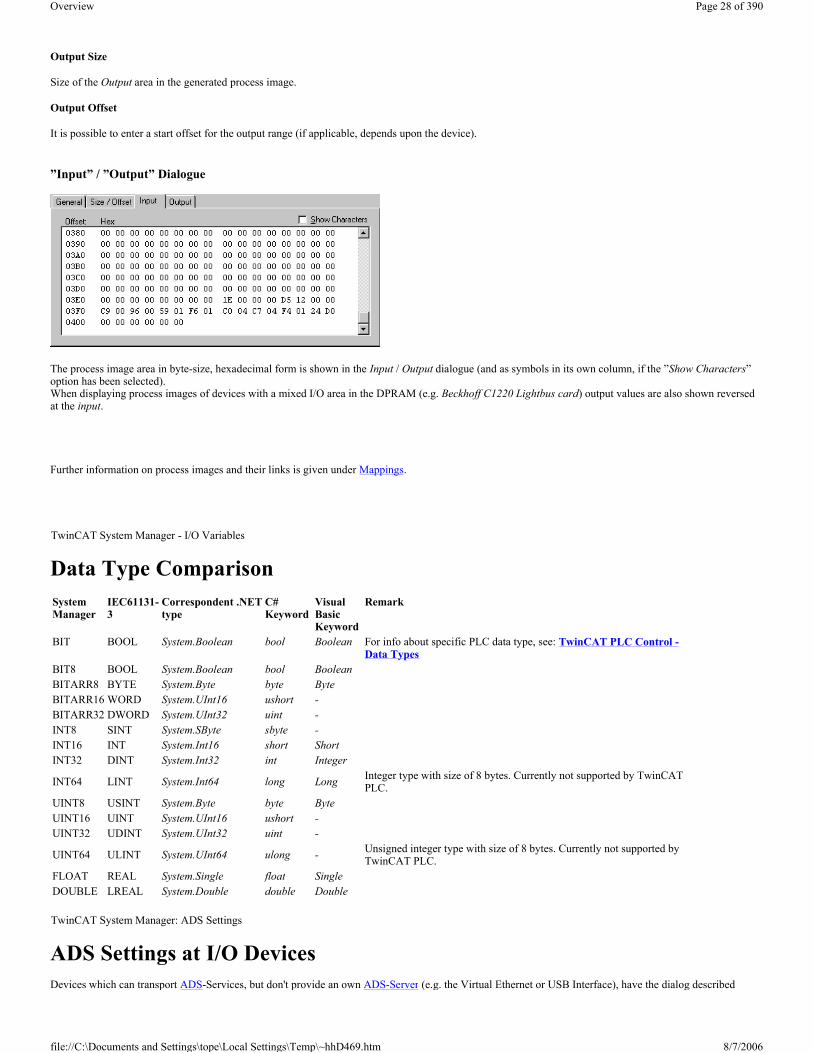
”Input” / ”Output” Dialogue
The process image area in byte-size, hexadecimal form is shown in the Input / Output dialogue (and as symbols in its own column, if the ”Show Characters”option has been selected). When displaying process images of devices with a mixed I/O area in the DPRAM (e.g. Beckhoff C1220 Lightbus card) output values are also shown reversed at the input.
Further information on process images and their links is given under Mappings.
Data Type Comparison
ADS Settings at I/O Devices Devices which can transport ADS-Services, but don't provide an own ADS-Server (e.g. the Virtual Ethernet or USB Interface), have the dialog described
TwinCAT System Manager - I/O Variables
System Manager
IEC61131-3
Correspondent .NET type
C# Keyword
Visual Basic Keyword
Remark
BIT BOOL System.Boolean bool Boolean For info about specific PLC data type, see: TwinCAT PLC Control -Data Types
BIT8 BOOL System.Boolean bool BooleanBITARR8 BYTE System.Byte byte ByteBITARR16 WORD System.UInt16 ushort -BITARR32 DWORD System.UInt32 uint -INT8 SINT System.SByte sbyte -INT16 INT System.Int16 short ShortINT32 DINT System.Int32 int Integer
INT64 LINT System.Int64 long Long Integer type with size of 8 bytes. Currently not supported by TwinCAT PLC.
UINT8 USINT System.Byte byte ByteUINT16 UINT System.UInt16 ushort -UINT32 UDINT System.UInt32 uint -
UINT64 ULINT System.UInt64 ulong - Unsigned integer type with size of 8 bytes. Currently not supported by TwinCAT PLC.
FLOAT REAL System.Single float SingleDOUBLE LREAL System.Double double Double TwinCAT System Manager: ADS Settings
Page 28 of 390Overview
8/7/2006file://C:\Documents and Settings\tope\Local Settings\Temp\~hhD469.htm

below.
"ADS" Tab
Enable ADS Communication
Activates the communication with ADS capable devices. This box has to be checked to allow ADS communication.
Port
Displays the ADS Port number of the device.
Change:
If this button is active, the ADS Port number can be changed here. Whether the change is possible or not, depends on the device type.
Max Timeout
Determines the allowed maximum response time for the ADS communication (in seconds).
ADS/AMS Settings at I/O-Devices Devices with own ADS-AmsNetId (e.g. the Beckhoff AX2000 drive) have the following dialog for ADS/AMS settings.
At devices without own NetId or e.g. devices without Beckhoff Lightbus interface, only a part of the following items are present on the tab, but the existing ones have the same meaning.
"ADS/AMS" Tab
Enable String Communication
Enables the asynchronous communication at devices with Beckhoff Lightbus interface .
Port
TwinCAT System Manager: ADS Settings
Page 29 of 390Overview
8/7/2006file://C:\Documents and Settings\tope\Local Settings\Temp\~hhD469.htm
Displays the ADS Port number of the current device.
Change
Makes a change of the Port number possible.
Max Timeout
Determines the allowed maximum response time for the ADS communication (in seconds).
Enable AMS / ADS
At devices with own NetId, this box has to be checked.
NetId
Displays the ADS-AmsNetId of this device.
Remote Name
Displays the name of this device as it appears in the list of possible -> "AMS Remote Connections". This field can be edited by user.
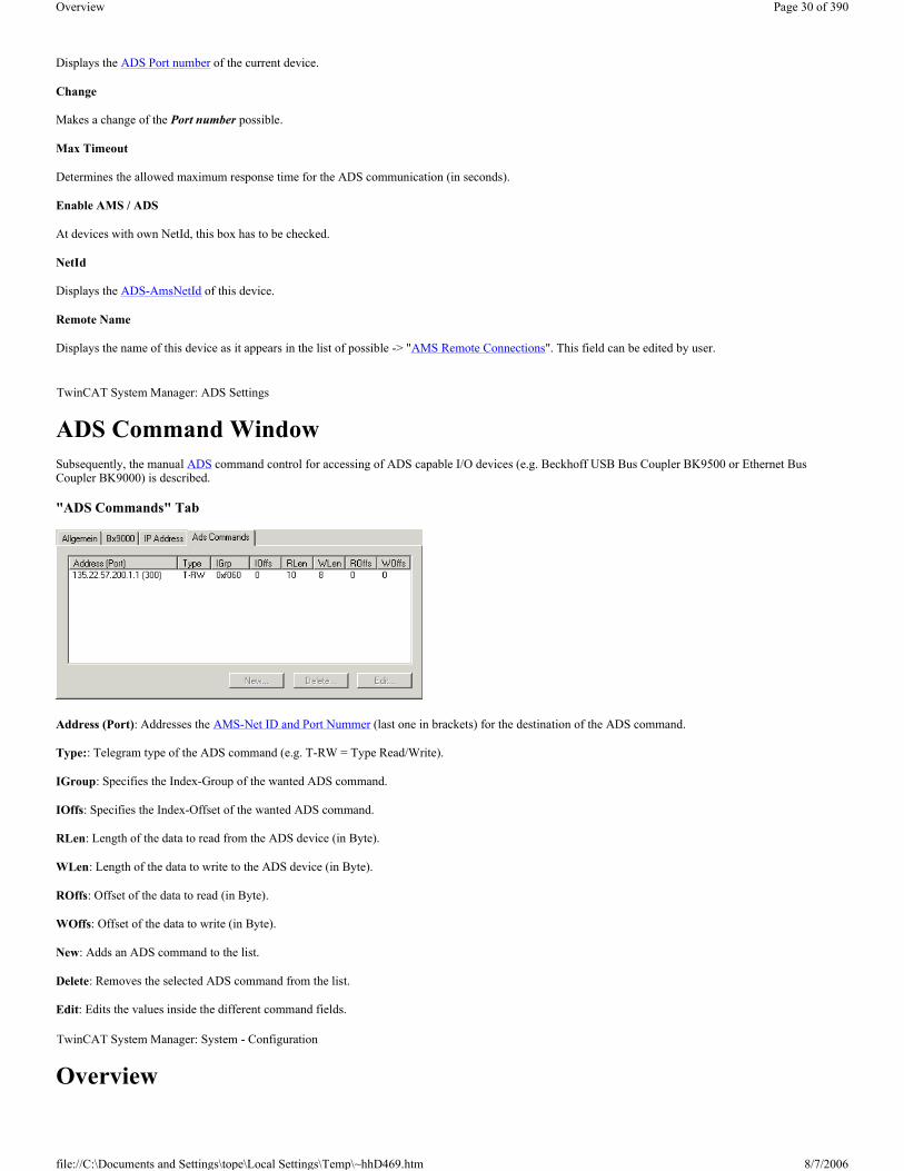
ADS Command Window Subsequently, the manual ADS command control for accessing of ADS capable I/O devices (e.g. Beckhoff USB Bus Coupler BK9500 or Ethernet Bus Coupler BK9000) is described.
"ADS Commands" Tab
Address (Port): Addresses the AMS-Net ID and Port Nummer (last one in brackets) for the destination of the ADS command.
Type:: Telegram type of the ADS command (e.g. T-RW = Type Read/Write).
IGroup: Specifies the Index-Group of the wanted ADS command.
IOffs: Specifies the Index-Offset of the wanted ADS command.
RLen: Length of the data to read from the ADS device (in Byte).
WLen: Length of the data to write to the ADS device (in Byte).
ROffs: Offset of the data to read (in Byte).
WOffs: Offset of the data to write (in Byte).
New: Adds an ADS command to the list.
Delete: Removes the selected ADS command from the list.
Edit: Edits the values inside the different command fields.
Overview
TwinCAT System Manager: ADS Settings
TwinCAT System Manager: System - Configuration
Page 30 of 390Overview
8/7/2006file://C:\Documents and Settings\tope\Local Settings\Temp\~hhD469.htm

At the SYSTEM - Configuration tree-entry, project-specific TwinCAT System- and Real-Time Settings can be made.
User-defined Tasks can also be created, e.g. to output or read I/O device values from high-level language applications (Visual Basic-, Visual C++, C# .NET, Visual Basic.NET or Delphi).
"General" Tab
This dialog only appears, if no Remote system is selected, means the System Manager accesses the local target system (see also "Choose Target System"). Besides that, the following dialog "Version [Local]" is equivalent.
"Version [Local]" Tab
The following dialog shows the installed TwinCAT Level of the lokale system (at this example it is "TwinCAT NC I" ) and the version und "Build"- number of it (correspondingly the version 2.9 [Build 931]).
"Version (Target)" Tab
Besides the info about the locally installed TwinCAT version, another tab with corresponding info about the selected TwinCAT target system is available. The following dialog shows e.g. version 2.9 [Build 0].
SYSTEM - Configuration DescriptionBoot Settings Boot / Auto-Logon settings for the local and for the target system Real-Time Settings Configuration of TwinCAT Real-Time settings and display for Real-Time loadPriorities Display / manipulation (= Advanced User) of TwinCAT Task prioritiesUser-defined Tasks ("Additional Tasks") Configuration of possible additional user-defined tasks Task settings for "Additional Tasks" (if configured) Dialog for settings of user-defined tasksOnline Display Task Load (if additional user-defined tasks are configured) Online view for the load of the user-defined task Task Process Images (if additional user-defined tasks are configured) Mapping informations about user-defined tasks Route Settings Informations about TwinCAT target system routing
Page 31 of 390Overview
8/7/2006file://C:\Documents and Settings\tope\Local Settings\Temp\~hhD469.htm

Choose Target: Calls the selection dialog for TwinCAT target systems, accessible by TwinCAT Router. See also: Main Menus -> "Actions"
Real Time Settings As a central configuration tool of the TwinCAT System, the TwinCAT System Manager contains below the rubric SYSTEM - Configuration the entry Real-Time Settings. This is where the basic TwinCAT system parameters are specified or changed if necessary.
If this entry is selected, the "Settings" dialog (described below), the "Online" and the "Priorities" dialog (described later) appear on the right-hand side in the System Manager.
”Settings” tab
TwinCAT System Manager: Real Time Configuration
Page 32 of 390Overview
8/7/2006file://C:\Documents and Settings\tope\Local Settings\Temp\~hhD469.htm

Base Time
The TwinCAT schedulers change on every tick from Windows to the TwinCAT real time. The planned and necessary task is then performed in TwinCAT real time. By the time the CPU limit (see below) has been reached, the system has changed back to Windows. The TwinCAT basis time is therefore the shortest possible task cycle time. The cycle time can also be a multiple of the basis time. The basis time should only be set to less than a millisecond if necessary and with correspondingly fast PC systems. The following are possible: (none), 1ms, 500µs, 333µs, 250µs, 200µs, 125µs, 100µs, 66µs and 50µs.
TwinCAT can be used without executed real-time by setting the Bse Time value to none, realtime will not be executed. Implementations which don´t need real-time, work as usual (AMS Router, TwinCAT Scope, ADS OCX, ...)
Restricitions:
Real-time tasks, like PLC tasks, software tasks and I/O tasks (Profibus, DeviceNet, Sercos or Lightbus) can not be executed.
CPU Limit
Specify the CPU percentage proportion that completely fills the TwinCAT real time, the remainder is reserved for Windows (and for surface programs). The value can be set very high since it is automatically reset to Windows when the real time task has completed its cycle.
Fast Tick
Only for special TwinCAT extensions which require a rapid tick irrespective of basis time (e.g. camshaft controller).
Latency Warning
The TwinCAT real time functions on practically all PC systems with extremely low fluctuations (Jitter). These jitters are measured continuously. If a pre-set limit is exceeded, the system can issue a warning.
Router Memory
Used to adjust the TwinCAT router memory settings. This memory is required for the internal communication.
”Online” tab
The online display gives information about the current CPU load. This is the amount of time required by the real time task. The bright green line indicates the pre-set CPU Limit value. In addition the current jitter (system latency time) is given in the bottom window.
Additional infos about the History View can be found under: Settings for History View.
"Priorities" tab
Information about the different priorities in the TwinCAT System, see: Priorities.
Page 33 of 390Overview
8/7/2006file://C:\Documents and Settings\tope\Local Settings\Temp\~hhD469.htm

NT Resources and the Realtime-Settings
One of the NT Task Manager's functions is to provide the user with a list of the running processes and of the amount of CPU time that they are using. A different interpretation must be given to the display when TwinCAT is running:
The TwinCAT real-time extension makes computing time available to the NT operating system. The NT operating system evaluates this portion as 100% CPU time. The display of the CPU time associated with processes in the NT task manager is thus not related to the CPU time itself, but to the remaining time still available to NT.
Example:
If TwinCAT requires a constant 50% of the CPU's capacity (see the "Realtime Settings"), and an additional process is displayed in the NT Task Manager with 50% "CPU time", it means that this process is actually using 25% of the real CPU time.
Real Time Configuration - Priorities In addition to the dialogues Settings and Online, contains the Real Time - Configuration area of the TwinCAT System Manager a dialog named Priorities.The dialog displays the priorities of the different tasks inside the TwinCAT System. With enabling of the Expert Mode it is even possible to change the priorities of the tasks, manually.
"Priorities" tab
Priority
Each TwinCAT Task has its own Priority in the system. The priority number is shown in this column. The lower the number, the higher the priority of the task. Additionally, each task type has a dedicated icon, shown in front of the number.
Cycle
Task cycle time in milliseconds.
Task
names the job of the task. At PLC tasks, it differs between
- PLC communication Task: This Task serves the ADS communication. To protect PLC data consistency, it should have the lowest priority level, referring
TwinCAT System Manager: Real Time Configuration
TwinCAT System Manager: Real Time Configuration
Page 34 of 390Overview
8/7/2006file://C:\Documents and Settings\tope\Local Settings\Temp\~hhD469.htm

to one PLC Run Time System.
- PLC Boost Priority: Priority of a PLC Task, as soon as it is in Monitoring / Debug mode. This Task should have the highest priority, referring to the Tasks of one PLC Run Time System.
- Common TwinCAT Task (light blue icon)
- reserved Priority for currently unused PLC Tasks (e.g. Task 1, 2 and 3 of a PLC Run Time System). The icon is grey (not active).
Comment
Describes the task origin (e.g. PLC Run Time System and project name).
Show All
Shows additionally the unused priorities of the available TwinCAT priorities.
Change Priorities
If Show All is activated, this checkbox enables the manipulation of the Task priorities inside the TwinCAT System.
Move Up
Moves the task priority up the list (and makes it therefore higher prior), if Expert Mode is enabled.
Move Down
Moves the task priority down the list (and makes it therefore lower prior), if Expert Mode is enabled.
PLC Standard
Organizes the priorities of the PLC Tasks like they are staggered by default (all Tasks of the 1st RTS in front of the tasks of the 2nd RTS and so on).
PLC Optimized
Organizes the Task priorities within the TwinCAT Systems in an optimal order in terms of execution of high prior task of different Run Time Systems. Means, the highest priority task of RTS 1 is followed by the Boost Priority Task of RTS 2 and then by the highest priority task of this RTS and so on.
Following picture shows an example of the staggered order for PLC Optimized:
User-defined Tasks (Additional Tasks) Overview
In addition to four PLC tasks per run-time system (and max. four PLC run-time systems), the TwinCAT system also supports further (non-PLC) software tasks which may possess I/O variables. These tasks are managed in the TwinCAT System Manager under the option ”Additional Tasks” (below ”SYSTEM -Configuration” in TwinCAT v2.9). These tasks can be used if a PLC is not available. Access to variables of these tasks can be gained directly from
TwinCAT System Manager: Real Time Configuration
Page 35 of 390Overview
8/7/2006file://C:\Documents and Settings\tope\Local Settings\Temp\~hhD469.htm

applications like TwinCAT OPC Server, Visual Basic, Delphi, VB.NET, VC++, C#.NET, etc.. e.g. via ADS-OCX, ADS-Dll or TcADS-DLL.
Note:
Settings carried out under this option require more advanced knowledge of the TwinCAT system.
Context Menu
Append Task
Adds another task.
Import Task
Integrates previously created and exported task into the existing system.
Paste
Inserts additional tasks from the clipboard.
Paste with Links
Inserts additional tasks with variable links from the clipboard.
The following dialogue appears after opting to Add a task:
The Name should be selected descriptively at this point. The nature of the user-defined task may also be outlined in a few sentences under Comment.
The new task then appears in the tree. This automatically contains the sub-menu options Process Image, Inputs and Outputs.
Further information about the inputs and outputs is given under: Variable Configuration.
Page 36 of 390Overview
8/7/2006file://C:\Documents and Settings\tope\Local Settings\Temp\~hhD469.htm

Task Context Menu
A right mouse click on the selected task displays the following context menu:
Export Task
Exports the task configurations with sub-elements and links into a file with the suffix *.tce. It can be thereby imported, as described earlier, into other projects.
Export Header File
Exports the configured input and output variables of the task into a C/C++ header file, for further use in TwinCAT Ring 3 I/O applications.
Cut
Copies the task to the clipboard and removes it from the current configuration.
Copy
Copies the task to the clipboard.
Disabled
Excludes the current task from calculation and editing by the TwinCAT system. Configurations and links are retained and are reactivated when this function is selected once more.
"Task" Dialog
There are different settings options for the tasks in the TwinCAT system. The effects and functions of these options are explained under Task Settings. The following option descriptions are for typical TwinCAT I/O applications.
Port
The ADS Port number of the specific ADS device. At the first additional task this is usually ADS Port number 301.
Auto-Start
Forces the TwinCAT System Manager to create the start command for this task. After start/restart of TwinCAT, this task is going to be started automatically with configured settings.
Page 37 of 390Overview
8/7/2006file://C:\Documents and Settings\tope\Local Settings\Temp\~hhD469.htm
Cycle ticks
The interval time for this task (with its attached variables) is to be configured here. A mapped Fieldbus (network) adaptor will be refreshed with this task interval then.
Create symbols
Should be activated to enable the symbol upload mechanism for this task e.g. for TwinCAT OPC Server v4 or TwinCAT Scope View. If this taks has e.g. the port number 301, an application like TwinCAT OPC Server v4 can upload the variables by name from this ADS Port number (with AutoCfg option type = 5).
"Online" Tab
For information about this dialog, see: Online Display of Task Load.
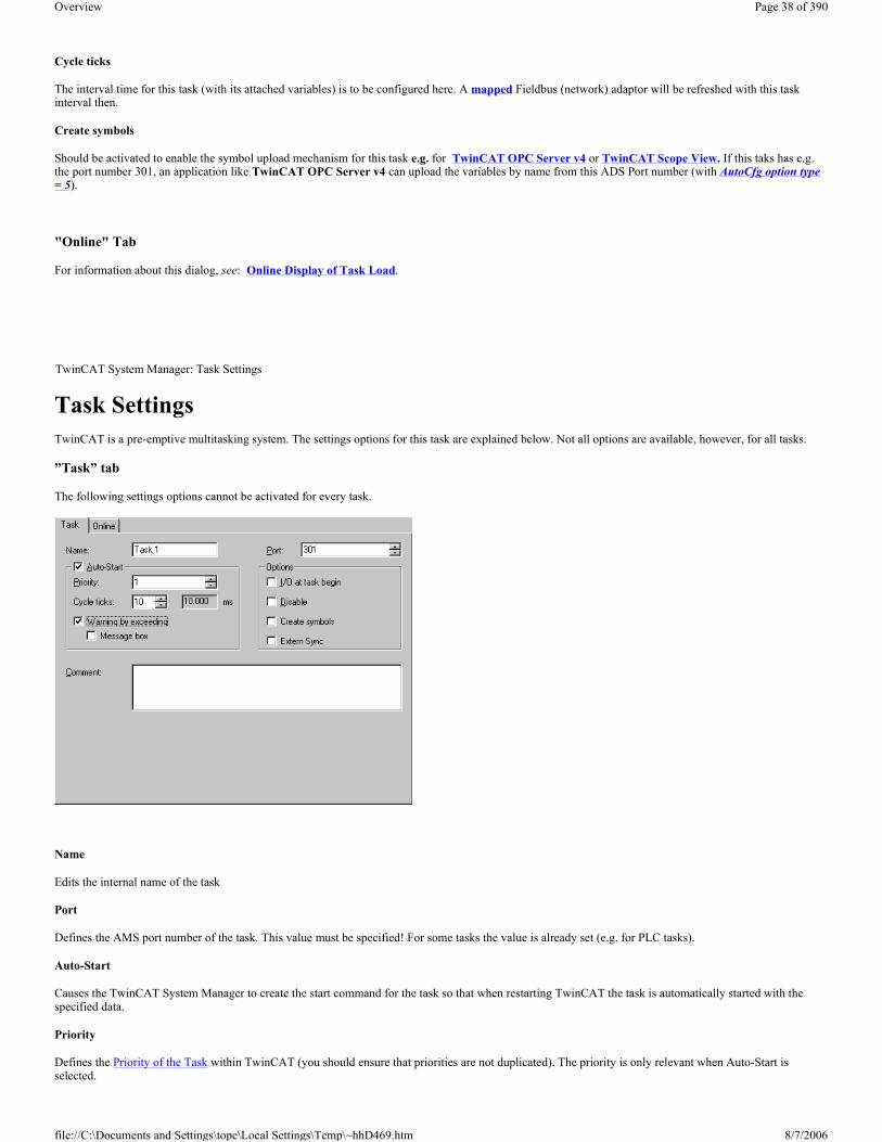
Task Settings TwinCAT is a pre-emptive multitasking system. The settings options for this task are explained below. Not all options are available, however, for all tasks.
”Task” tab
The following settings options cannot be activated for every task.
Name
Edits the internal name of the task
Port
Defines the AMS port number of the task. This value must be specified! For some tasks the value is already set (e.g. for PLC tasks).
Auto-Start
Causes the TwinCAT System Manager to create the start command for the task so that when restarting TwinCAT the task is automatically started with the specified data.
Priority
Defines the Priority of the Task within TwinCAT (you should ensure that priorities are not duplicated). The priority is only relevant when Auto-Start is selected.
TwinCAT System Manager: Task Settings
Page 38 of 390Overview
8/7/2006file://C:\Documents and Settings\tope\Local Settings\Temp\~hhD469.htm

Cycle Ticks
Sets the cycle time in ticks (depends upon the pre-set TwinCAT Base Time). of the task. The cycle time is only relevant when Auto-Start is selected.
Warning by exceeding
Causes the TwinCAT to issue a warning when the pre-set task cycle time is exceeded.
Message box
Outputs the warning (above) also as a message box.
I/O at task begin
An I/O cycle is carried out at the beginning of the task.
Disable
Allows occasional task-disablement, i.e. the task is ignored when generating the I/O information (e.g. during commissioning). The link information is, however, retained.
Create Symbols
Allows access to variables of the corresponding task via ADS (e.g. from TwinCAT Scope View). Further information is given under: Variable Configuration.
Extern Sync
Is this option activated, this Task will be synchronized with a configured device with Master Sync Interrupt (e.g. a SERCOS card).
”Online” tab
Here you can find information on the Online Display of Task Load.
Online Display of Task Load When the current configuration is loaded, the task load values can be graphically displayed under ”Online”.
”Online” tab
”CPU” display
Shows the CPU time required for the last task execution.
”Total” display
TwinCAT System Manager: Real Time Configuration
Page 39 of 390Overview
8/7/2006file://C:\Documents and Settings\tope\Local Settings\Temp\~hhD469.htm

Gives the time that has passed between the start and the end of the task execution. The difference between CPU and absolute (total) execution time can result, for example, from an interruption of the current task by a higher priority task or by Windows.
Exceed counter
Counts the number of cycle time limit exceeded.
Reset
Resets the exceeded limit counter to 0.
Additional infos about the History View can be found under: Settings for History View.
Boot Settings Under preparation...
Route Settings Under preparation...
"Current Routes" tab
Route
Shows the name of the TwinCAT target system currently listed at the local TwinCAT Router.
AmsNetID
Displays the ADS-AmsNetId of the listed target system.
Adresse
Shows the ( TCP/IP ) address of the listed target.
Type
Names the protocol used for this target.
TwinCAT System Manager: Real Time Configuration
TwinCAT System Manager: Real Time Configuration
Page 40 of 390Overview
8/7/2006file://C:\Documents and Settings\tope\Local Settings\Temp\~hhD469.htm

Comment
If configured at the target system, the comment is shown here.
Add
Calls the configuration dialog for adding additional target systems to the local TwinCAT Router.
Remove
Deletes marked entries from the routing table of the local TwinCAT Router.
Properties
Calls the dialog for showing the "Properties" of the target system.
"Static Routes" tab
For the description of the column headers and buttons, see "Current Route" tab.
"Project Routes" tab
For the description of the column headers and buttons, see "Current Route" tab.
Page 41 of 390Overview
8/7/2006file://C:\Documents and Settings\tope\Local Settings\Temp\~hhD469.htm

Overview If TwinCAT is installed with NC function capability (minimum: TwinCAT Level NC PTP) you will see "NC Configuration" in the tree view of the System Manager. Here you can create the required axes and set their parameters. When TwinCAT is started, it's also possible to drive axes via corresponding online dialogues (NC Manual Menu, Online Display of Axis Channel) and carry out other NC axis functions like manual coupling etc..).
"General" Tab
This dialog only appears, if no Remote system is selected, means the System Manager accesses the local target system (see also "Choose Target System"). Besides that, the following dialog "Version [Target]" is equivalent.
Dialog "Version [Target]"
The following dialog describes the TwinCAT server of the target system, where this module is based on. In the shown dialog this is the - currently active - version 2.9 [Build 531] of the TwinCAT NC Server.
Overview If TwinCAT is installed with PLC function capability (minimum TwinCAT Level PLC) you will see "PLC - Configuration" in the tree view of the System Manager. PLC projects can be added here and their settings (number of run-time systems, port no., cycle times, …) checked. The path settings for the PLC project can also be adjusted accordingly.
TwinCAT System Manager: NC Configuration
NC - Configuration DescriptionTasks NC task settingsChannel Information about axis channelAxes Configuration of individual axes Cam Design Configuration of Cam plates with TwinCAT Cam Design Tool Hydraulic Valve Diagrams Configuration of special characteristics for hydraulic valves with TwinCAT Valve Diagram Editor
TwinCAT System Manager: PLC Configuration
PLC - Configuration DescriptionPLC Settings Settings according to the PLC environment (Number of Run-Time systems, handling of persistent data, etc..)PLC Project Settings ("IEC1131") Project pathes and other informations about the associated PLC project(s)Prozess Images Overview about the mappings between PLC variables and other process images (I/O devices, NC variables,...) Task Informations about the tasks contained in the associated PLC project(s)
Page 42 of 390Overview
8/7/2006file://C:\Documents and Settings\tope\Local Settings\Temp\~hhD469.htm

"General" Tab
This dialog only appears, if no Remote system is selected, means the System Manager accesses the local target system (see also "Choose Target System"). Besides that, the following dialog "Version [Target]" is equivalent.
"Version [Target]" Tab
The following dialog describes the TwinCAT server of the target system, where this module is based on. In the shown dialog this is the - currently active - version 2.9 [Build 431] of the TwinCAT PLC Server.
Generating a PLC Configuration Select PLC Configuration in the tree view of the System Manager and then right click on the mouse to open the corresponding context menu.
Context menu:
Append IEC Project
Opens a dialog to select and add a PLC project to the configuration.
Paste
Adds the PLC project which is currently on the clipboard to the configuration.
Paste with Links
Command does the same like Paste, but tries to restore available variable links.
TwinCAT System Manager: PLC Configuration
Page 43 of 390Overview
8/7/2006file://C:\Documents and Settings\tope\Local Settings\Temp\~hhD469.htm

"IEC61131" tab
When a project was generated with TwinCAT PLC Control without errors and then saved, a PLC configuration can be added to to the current system configuration and the I/O variables with address locations are read in. When you select the added PLC project in the tree the associated dialogue IEC1131 appears on the right-hand side.
Project
Shows the name of the currently selected PLC project.
Path
Defines the path of the current PLC project. This path indicates the PLC project currently referenced to this configuration.
Note:
In TwinCAT version 2.7, the path points to a *.pro file, on the contrary in TwinCAT 2.8 it does to a new file with the extension *.tpy. This new *.tpy file which is XML-based, contains located PLC variables and their addresses as well as generic project information.
Additionally, another new XML-based file type with the extension *.tpa has been launched with TwinCAT 2.8. The *.tpa file contains the resolved address of VAR_CONFIG variables (%I*, %Q*) eventually configured under Variable_Configuration or Global_Variables. The resolved addresses are shown under Resources | "TwinCAT_Configuration (VAR_CONFIG)" within TwinCAT PLC Control.
Run-Time No.
Gives the Run-time System for which the selected PLC project is configured. Settings changes can be
carried out under Online Settings in the TwinCAT PLC Control.
Port
Defines the AMS Port Number of the run-time system. The number shown depends on the Run-time Number described above.
Target System
Defines the target system for which the respective PLC code was generated. If the PLC is running on the PC, code i386 is generated.
I/O at Task Begin
An I/O cycle is carried out at the task start. This means a jitter-free cycle of the I/O independent of the run-time of the task (normally not activated for PLC configurations).
Task cycle time interpreted as ticks
This checkbox is deactivated by default. It is only in use, when the TwinCAT Base Time differs from its default value of 1ms. This is e.g. the case, when a PLC Task interval less than 1ms is wanted.
ReScan
Re-loads the current PLC configuration into the system. Changed configurations (e.g. new I/O variables) will then appear in the System Manager configuration.
Change
This command enables the path for the PLC project to be adjusted. This is necessary if the project location has changed or if you want to activate another PLC project.
PLC Configuration - Process Image
Page 44 of 390Overview
8/7/2006file://C:\Documents and Settings\tope\Local Settings\Temp\~hhD469.htm

Below the PLC project name appears an input ‘Project Name’ - Process Image (as shown below). Further information is given under: Process Images.
PLC Configuration - Task Information
If the tree below the process image is opened as shown below you will see the name of the task configured in the PLC project. The corresponding dialogue appears on the right-hand side in the System Manager, see Task Settings.
As a PLC project can comprise up to 4 tasks, several task names will appear in the corresponding multitasking projects in the tree. This is shown in the diagram below for both ‘Standard’ and ‘FastTask’ tasks.
The input and output variables are always assigned to the first task after loading the PLC project, but can also be assigned to other tasks, e.g. via Drag&Drop. This means that the values of the variables can be refreshed according to the current pre-set task cycle times.
If you select an input or output variable, this can be linked either with the context menu or the dialogue which appears on the right-hand side, via a Variable Link.
Extended Link Options
Further link and documentation functions for variable lists are described here.
TwinCAT System Manager: PLC Configuration
Page 45 of 390Overview
8/7/2006file://C:\Documents and Settings\tope\Local Settings\Temp\~hhD469.htm

PLC Settings Under preparation..
Overview The I/O - Configuration is an important component of the TwinCAT System Manager. The lowest level of TwinCAT is TwinCAT Level I/O, means an I/O Configuration entry in the TwinCAT System Manager tree- view is always present. After the various Configurations have been executed for the different tasks and the System Manager has been acquainted with all relevant variables, the hardware (usually a fieldbus with I/O modules) is configured under this rubric. It is also possible to configure the I/O section first and the other tasks (e.g. PLC tasks) later on, of course.
"General" Tab
This dialog only appears, if no Remote system is selected, means the System Manager accesses the local target system (see also "Choose Target System"). Besides that, the following dialog "Version [Target]" is equivalent.
"Version [Target]" Tab
The following dialog describes the TwinCAT server of the target system, where this module is based on. In the shown dialog this is the - currently active - version 2.9 [Build 418] of the TwinCAT IO Server.
Adding an I/O Device Click on the right-hand mouse button on I/O Devices to display the following context menu:
TwinCAT System Manager: I/O - Configuration
I/O - Configuration
Description
I/O Devices At target system (local or remote) configured Input and Output devices (Fieldbus cards, NOVRAM, system interfaces,..) and their process images
Mappings Informations about mappings between the I/O devices and other TwinCAT devices, resp. their process images
TwinCAT System Manager: I/O - Configuration
Page 46 of 390Overview
8/7/2006file://C:\Documents and Settings\tope\Local Settings\Temp\~hhD469.htm

Append Device
Opens the Selection Dialog for the supported fieldbus cards and other hardware devices (e.g. common PC interfaces, etc..).
Import Device
Integrates previously created and exported I/O configurations into the current System Manager project.
Scan Devices
Scans the PC for supported I/O devices. Found devices are listed afterwards under I/O Devices in the treeview. From TwinCAT 2.9 on, the target system has to be in Config Mode for this function.
Paste
Adds another device to the current position (before marked device) in the configuration.
Paste with Links
Does the same as Paste, but adopts previously created variable links from the imported file.
After installing a device the property pages dialog appears on the right hand side in the System Manager view. Further information about dialog ”General”: Dialog "General".
Further information about I/O devices: Reference | I/O DevicesThe current values in the dual port memory can be viewed online via the DPRAM (Online).
I/O Devices - Process Image
Below the device name appears an input box ‘Device Name’-Process Image. Further information is given under: Process Images.
I/O Devices - Status and Control Information
After opening the tree below the I/O device, you will find the status and control information on the selected device.
Page 47 of 390Overview
8/7/2006file://C:\Documents and Settings\tope\Local Settings\Temp\~hhD469.htm

These are input and output variables which can be linked as standard, e.g. with matching PLC variables, and which can therefore indicate the status of the device to the PLC run-time system. Further information about the topic of links can be found under: Variable Links.
Adding In/Output Modules
The selection and configuration of the various I/O modules (boxes) is described under: "Adding Input/Output Modules (boxes)".
Select I/O Device After executing Append Device..., the following dialog appears to choose the specific I/O device (several Fieldbus cards, Beckhoff-specific Hardware, common PC interfaces,...):
In the tree-view of this selection dialog, you'll find all available I/O devices (see also "Target Type"), in above example e.g. a Beckhoff Lightbus card. For a detailed list see: I/O Devices in the Reference chapter.
Type
Offers all I/O devices for the respective Fieldbus.
Name
The description of the device can be edited here.
TwinCAT System Manager: I/O - Configuration
Page 48 of 390Overview
8/7/2006file://C:\Documents and Settings\tope\Local Settings\Temp\~hhD469.htm

Target Type
Provides a filter for limiting the shown devices to the respective Beckhoff platform to be configured in this session. Nevertheless, default setting is "All".
Ok
Confirms the selection of the device and closes the dialog. Alternatively, a selection of the I/O device with double-click is possible to close this dialog automatically.
Cancel
Closes the dialog without adding a device to the current configuration.
Adding Input/Output Modules (boxes) The various input and output modules (boxes) are now added and configured and/or linked with the variables of the PLC projects or other run-time systems (e.g. of an Additional Task) below the configured fieldbus cards.
A right mouse click on the Configured I/O Device (the example shows a Beckhoff FC200x Lightbus PCI card) displays a context menu. As the name says, this menu is context-dependant, i.e. different fieldbus cards often have different context menus. In the following description, therefore, only the general menu entries are discussed. You can obtain detailed device information from the Technical Reference.
Append Box
Calls up, depending on the configured fieldbus system, the Selection Diagram for the supported I/O module.
Delete Device
Deletes the I/O device from the tree view and thereby from the configuration.
Online Reset
Actuates an I/O reset on the card. This is only possible, of course, for active configurations and when the system is running.
Export Device
Saves the entire configuration (with all added boxes) for the selected device into an export file.
Import Box
TwinCAT System Manager: I/O - Configuration
Page 49 of 390Overview
8/7/2006file://C:\Documents and Settings\tope\Local Settings\Temp\~hhD469.htm
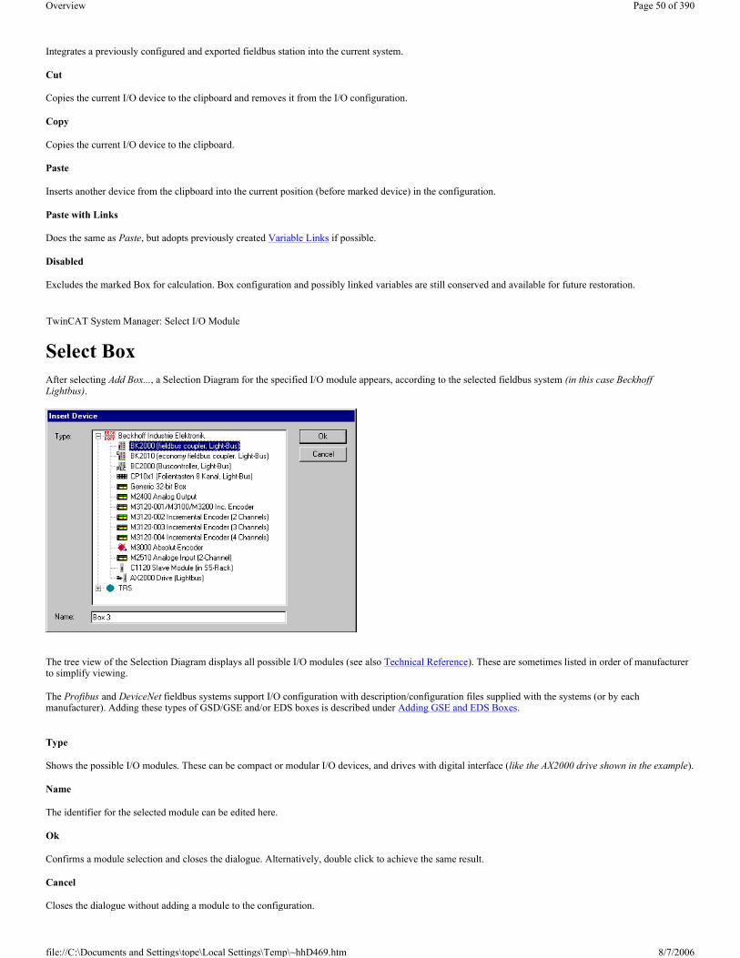
Integrates a previously configured and exported fieldbus station into the current system.
Cut
Copies the current I/O device to the clipboard and removes it from the I/O configuration.
Copy
Copies the current I/O device to the clipboard.
Paste
Inserts another device from the clipboard into the current position (before marked device) in the configuration.
Paste with Links
Does the same as Paste, but adopts previously created Variable Links if possible.
Disabled
Excludes the marked Box for calculation. Box configuration and possibly linked variables are still conserved and available for future restoration.
Select Box After selecting Add Box..., a Selection Diagram for the specified I/O module appears, according to the selected fieldbus system (in this case Beckhoff Lightbus).
The tree view of the Selection Diagram displays all possible I/O modules (see also Technical Reference). These are sometimes listed in order of manufacturer to simplify viewing.
The Profibus and DeviceNet fieldbus systems support I/O configuration with description/configuration files supplied with the systems (or by each manufacturer). Adding these types of GSD/GSE and/or EDS boxes is described under Adding GSE and EDS Boxes.
Type
Shows the possible I/O modules. These can be compact or modular I/O devices, and drives with digital interface (like the AX2000 drive shown in the example).
Name
The identifier for the selected module can be edited here.
Ok
Confirms a module selection and closes the dialogue. Alternatively, double click to achieve the same result.
Cancel
Closes the dialogue without adding a module to the configuration.
TwinCAT System Manager: Select I/O Module
Page 50 of 390Overview
8/7/2006file://C:\Documents and Settings\tope\Local Settings\Temp\~hhD469.htm

Adding GSD and EDS Boxes The Profibus and DeviceNet fieldbus systems contain device-specific configuration files which are provided by the hardware manufacturers. These serve to integrate these external devices into any control system that supports that fieldbus. The files are described under Profibus as GSD and under DeviceNet as EDS (Electronic Data Sheet) files.
After selecting Append Box..., depending upon the selected fieldbus system (in this case Profibus), a ‘Generic Profibus Box (GSD)’ item is shown under Miscellaneous.
In the case of DeviceNet you would see ‘General DeviceNet Box (EDS)‘.
With double-click or press on Ok, a Windows file-selection dialog shows available *.gsx files stored in the \TwinCAT\IO\GSD directory.
Press the Open button to integrate the device into the System Manager configuration. Notice: The device manufacturers are responsible for the GSD and/or ESD files, i.e. Beckhoff Automation GmbH does not provide GSD/GSE (GSE = GSD files in English) or EDS files for 3rd party devices, nor does it offer any guarantee of their function.
Device description
The specific structure of the GSD/GSE and/or ESD files (specified by the corresponding user organisations (PNO and ODVA respectively) allows the TwinCAT System Manager to read and display device information (manufacturer, device type etc.). This is shown in the right-hand General dialogue for the
TwinCAT System Manager: Select I/O Module
Page 51 of 390Overview
8/7/2006file://C:\Documents and Settings\tope\Local Settings\Temp\~hhD469.htm

device selected in the tree.
The dialogue contains the device name, type, manufacturer and GSD/GSE and/or EDS file revision number. The latter can be of particular importance if there is any confusion over currently valid versions. There is also a "Checkbox" for disabling the device, i.e. if selected, the device will be excluded on the driver side from the current combination of the fieldbus telegram, but can be retained on the hardware side unless the address is assigned to another device.
Compact and Modular Devices
The integrated external devices may be compact or modular. In the case of a compact device, the length of the input and output data transferred by the fieldbus can be pre-set. In the case of a modular device the number of the input and output data bytes of the device can be configured. Further details are given in the Technical Reference (see Modular Profibus Devices), along with details about the specific settings for the Profibus tab seen above (see GSD Device). You will find information about the DeviceNet fieldbus system under DeviceNetNode.
Adding Bus Terminals (KLxxx) The various input and output terminals are added and the channels are linked with task variables beneath the configured Bus Coupler.
A right mouse click on the Configured Box (the example shows a Beckhoff BK2000 Bus Coupler) opens the following context menu:
Context menu
TwinCAT System Manager: I/O - Configuration
Page 52 of 390Overview
8/7/2006file://C:\Documents and Settings\tope\Local Settings\Temp\~hhD469.htm

Append Terminal
Calls up the Selection Diagram for the various Beckhoff Bus Terminals.
Insert Box Before
Adds a box in front of the box currently selected in the tree (in this case, box 1).
Delete Box
Deletes the box from the tree view and thereby from the configuration.
Import Box Before
Integrates a previously configured and exported fieldbus station into the current system.
Export Box
Saves the selected fieldbus station to an export file (*.tce).
Cut
Copies the currently selected fieldbus station to the clipboard and removes it from the I/O configuration.
Copy
Copies the current fieldbus station to the clipboard.
Paste
Inserts another box from the clipboard into the current position (before the marked device) in the configuration.
Paste with Links
Does the same as Paste, but reconnects previously created variable links if possible.
Disabled
Removes the box from the current system configuration (excludes it from calculation) without deleting it. The box can be reactivated at any time.
Terminal Selection Diagram After selecting Add Terminal..., you will see a Selection Diagram for the various terminals. Bus Terminal Controller (BC) terminals are described under Terminal selection for Bus Terminal Controllers.
TwinCAT System Manager: Select I/O Module
Page 53 of 390Overview
8/7/2006file://C:\Documents and Settings\tope\Local Settings\Temp\~hhD469.htm

Details about the various Beckhoff Bus Terminals are described under Terminals - Technical Reference.
Type
The list shows the different Beckhoff Bus Terminals sorted by their main groups.
Name
Here you can edit the identifier for the selected terminal, which should appear in the tree view.
Multiple
Inserts n terminals of the selected type continuously into the configuration.
OK
Integrates the selected terminals into the configuration.
Cancel
Closes the dialogue without adding a terminal to the configuration.
You can find further information about the configuration of the terminals in the System Manager under: Terminal Configuration.
Terminal Configuration Once a terminal has been added it will appear in the System Manager tree view. On the right hand side you will see the general and terminal-specific dialogues:
Name
In this view you can edit the identifier for the selected terminal, which will then appear in the tree view and in the Exporting Variables Information.
Type
Names the selected terminal type and its function.
Comment
User-defined comment on the terminal to be used (e.g. specific, user-defined settings in the terminal registers). The comment given here is also displayed when performing configurations under Bus Terminal Controller - Configurations, the subsequent Exporting Variables Information and in the Global BC Variable List. This information also appears when importing I/O variables into the TwinCAT OPC Server.
Disabled
Disables the terminal input for the current configuration (transparent), i.e. the terminal is excluded from the configuration and calculation.
TwinCAT System Manager: Select I/O Module
Page 54 of 390Overview
8/7/2006file://C:\Documents and Settings\tope\Local Settings\Temp\~hhD469.htm
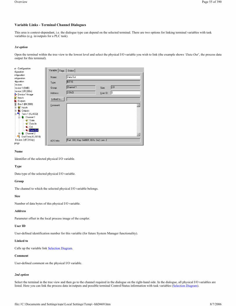
Variable Links - Terminal Channel Dialogues
This area is context-dependant, i.e. the dialogue type can depend on the selected terminal. There are two options for linking terminal variables with task variables (e.g. in/outputs for a PLC task).
1st option
Open the terminal within the tree view to the lowest level and select the physical I/O variable you wish to link (the example shows ‘Data Out’, the process data output for this terminal).
Name
Identifier of the selected physical I/O variable.
Type
Data type of the selected physical I/O variable.
Group
The channel to which the selected physical I/O variable belongs.
Size
Number of data bytes of this physical I/O variable.
Address
Parameter offset in the local process image of the coupler.
User ID
User-defined identification number for this variable (for future System Manager functionality).
Linked to
Calls up the variable link Selection Diagram.
Comment
User-defined comment on the physical I/O variable.
2nd option
Select the terminal in the tree view and then go to the channel required in the dialogue on the right-hand side. In the dialogue, all physical I/O variables are listed. Here you can link the process data in/outputs and possible terminal Control/Status information with task variables (Selection Diagram).
Page 55 of 390Overview
8/7/2006file://C:\Documents and Settings\tope\Local Settings\Temp\~hhD469.htm

Details about the various Beckhoff Bus Terminals are described under Terminals - Technical Reference.
Overview At some fieldbus cards (e.g. Ethernet, Profibus, Interbus and Lightbus) you can add programmable Bus Terminal Controllers (BC) as well as the standard in/output modules (boxes). These controllers are bus couplers with PLC functionality. This device type requires additional settings which are described under Bus Terminal Controller Configuration.
Context Menu, Bus Terminal Controller Right mouse click below I/O Devices on Added Box (the example shows a Beckhoff BC3100 Profibus BC) to open a context menu with the following inputs:
Append Terminal
TwinCAT System Manager: Bus Terminal Controller Configurations
TwinCAT System Manager: Bus Terminal Controller Configurations
Page 56 of 390Overview
8/7/2006file://C:\Documents and Settings\tope\Local Settings\Temp\~hhD469.htm
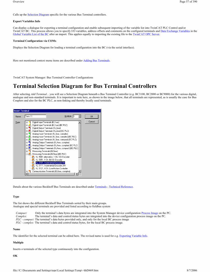
Calls up the Selection Diagram specific for the various Bus Terminal controllers.
Export Variables Info
Can display a dialogue for exporting a terminal configuration and enable subsequent importing of the variable list into TwinCAT PLC Control and/or TwinCAT BC. This process allows you to specify I/O variables, address offsets and comments on the configured terminals and Data Exchange Variables in the Global Variable List of the BC after an import. This applies equally to importing the existing file to the TwinCAT OPC Server.
Terminal Configuration via COMx
Displays the Selection Diagram for loading a terminal configuration into the BC (via the serial interface).
Here not mentioned context menu items are described under Adding Bus Terminals.
Terminal Selection Diagram for Bus Terminal Controllers After selecting Add Terminal... you will see a Selection Diagram beneath a Bus Terminal Controller (e.g. BC3100, BC2000 or BC9000) for the various digital, analogue and non-standard terminals. It is important to note here, as shown in the image below, that all terminals are represented, as is usually the case for Bus Couplers and also for the BC PLC, as non-linking and thereby locally used terminals.
Details about the various Beckhoff Bus Terminals are described under Terminals - Technical Reference.
Type
The list shows the different Beckhoff Bus Terminals sorted by their main groups. Analogue and special terminals are provided and listed according to fieldbus system
Compact: Only the terminal’s data bytes are integrated into the System Manager device configuration Process Image on the PC. Complex: The terminal’s data and control/status bytes are integrated into the device configuration process image on the PC. PLC - compact: The terminal’s data bytes provided only, and only for the local BC process image
PLC - complex: The terminal’s data and control/status bytes, for the local BC process image.
Name
The identifier for the selected terminal can be edited here. The revised name is used for e.g. Exporting Variable Info.
Multiple
Inserts n terminals of the selected type continuously into the configuration.
OK
TwinCAT System Manager: Bus Terminal Controller Configurations
Page 57 of 390Overview
8/7/2006file://C:\Documents and Settings\tope\Local Settings\Temp\~hhD469.htm

Integrates the selected terminals into the configuration.
Cancel
Closes the dialogue without adding a terminal to the configuration.
You can find further information about the configuration of the terminals in the System Manager under: Terminal-specific Dialogues.
Data Exchange PC/Bus Terminal Controller For Bus Terminal controllers you can define below PLC variables data exchange variables (see example in the tree view below) for the fieldbus-based PC to PC communication. If you select a BC in the tree view of the TwinCAT System Manager, the following BC Mini PLC dialogue (amongst others) will appear on the right-hand side:
”PLC” Dialogue
PLC Cycle Time
The reserved Mini PLC cycle time. During this period, no data will be sent by the BC to the fieldbus.
Background Time
Time for the processing of the communication via the fieldbus (includes program download, debugging,..).
PLC Var. Offs IN
Start offset of the data exchange variables in the input area of the BC Process Image.
PLC Var. Offs OUT
Start offset of the data exchange variables in the output area of the BC Process Image.
AMS Response during download
Can be disabled for compatibility reasons in old Bus Terminal controllers (BC3100 and BC2000). Newer bus controller firmware versions acknowledge the receipt of individual download sequences. This checkbox must therefore be activated (in all cases for BC9000).
Start with Configuration Error
Even if the configured BC9000 is not connected to the network, it is possible to start the TwinCAT system if this checkbox is enabled.
Retain Data
Store Retain Data: Activates the support of residual data in the Bus Terminal controller.
Size: Size of the retain data area within the Bus Terminal controller (%Mx0 .. %Mxy).
KBus Update
Double Cycle: Activates the execution of BC station I/O cycles (KBus Update) within before and after each PLC cycle.
Before PLC: A KBus update will be carried out before executing the PLC cycle.
After PLC: A KBus update will be carried out after executing the PLC cycle.
TwinCAT System Manager: Bus Terminal Controller Configurations
Page 58 of 390Overview
8/7/2006file://C:\Documents and Settings\tope\Local Settings\Temp\~hhD469.htm
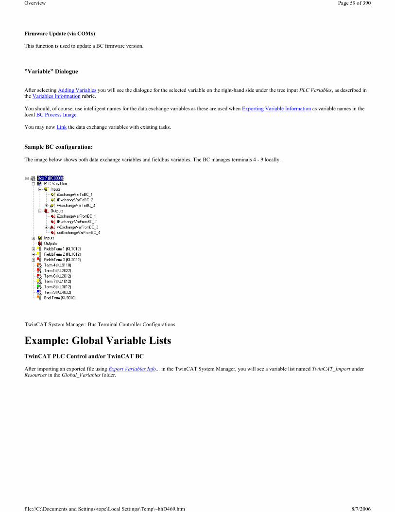
Firmware Update (via COMx)
This function is used to update a BC firmware version.
”Variable” Dialogue
After selecting Adding Variables you will see the dialogue for the selected variable on the right-hand side under the tree input PLC Variables, as described in the Variables Information rubric.
You should, of course, use intelligent names for the data exchange variables as these are used when Exporting Variable Information as variable names in the local BC Process Image.
You may now Link the data exchange variables with existing tasks.
Sample BC configuration:
The image below shows both data exchange variables and fieldbus variables. The BC manages terminals 4 - 9 locally.
Example: Global Variable Lists TwinCAT PLC Control and/or TwinCAT BC
After importing an exported file using Export Variables Info... in the TwinCAT System Manager, you will see a variable list named TwinCAT_Import under Resources in the Global_Variables folder.
TwinCAT System Manager: Bus Terminal Controller Configurations
Page 59 of 390Overview
8/7/2006file://C:\Documents and Settings\tope\Local Settings\Temp\~hhD469.htm

The variables are composed of the Names configured in the System Manager and the type of terminal, along with the channel number and the definition of the terminal variable. The address in the local BC process image (IEC61131-3 notation) and the data type of the variables are given.
The variables in lines 2 to 8 are Exchange Variables (PLC Variables) to be transferred via the fieldbus.They serve to exchange data between the BC PLC program and the superordinate control system. They can, for instance, be processed further with TwinCAT PLC, TwinCAT OPC or via ADS on the application level. For example, the declared output variables for the outputs process image (lines 2, 3 and 4) are inputs in the superordinate control system. The variables of lines 5 - 8 are correspondingly outputs of the superordinate control system.
The exchange variables in the local BC process image start from offset 128 (as shown in the example). Nevertheless, this offset can also be set in a System Manager dialogue if necessary.
Details on the different Beckhoff Bus Terminal types (e.g. definition of descriptors Ctr1 and State and Data_x) are described under Terminals - Technical Reference.
Merging the BC2000 in the TwinCAT system manager
basic properties:
The basic properties of the bus terminal controller are handled in the system manager. The terminals of the bus terminal controller can be assigned directly to the Lightbus master or to the BC2000. Terminals that are assigned directly to the BC2000 are displayed in the system manger with "PLC", and are not visible to the master. A further distinction between "Complex" and "Compact" is also made in the analogue terminals.
Complex: complete representation of the analogue terminals with control/status, 4 bytes input/output per channel
Compact: user data only, 2 bytes per channel
The terminals that are assigned to the master are invisible to the bus terminal controller. If it is desired to make a terminal visible to both systems, the terminal must first be assigned to the BC2000, and then the data from the terminal are transmitted to the master via the PLC variables.
TwinCAT System Manager: Bus Terminal Controller Configurations
Page 60 of 390Overview
8/7/2006file://C:\Documents and Settings\tope\Local Settings\Temp\~hhD469.htm

The settings for the PLC in the bus terminal controller are found under the "PLC" tab. All the basic settings that control the properties of the PLC in the BC2000 are handled there.
PLC Cycle Time
The PLC cycle time determines the program's repetition frequency. This time is not deterministic. This means that when the program in the bus terminal controller needs more time, the PLC cycle time rises. If the program needs less than the cycle time, it is repeated at intervals of the set cycle time.The processing of the Lightbus and the serial interfaces is executed in the background time. This should be set to approx. 20 % of the PLC cycle time.
The "mean cycle time" is measured in order to optimise the system. You will find this item in PLC Control under Online\Coupler. About 20% - 30% is added to this, and the result entered as the PLC cycle time. The background time is then set to 20% of the PLC cycle time.
PLC cycle time = mean cycle time + 20% = 10 ms + 20% = 12 ms Background time = PLC cycle time * 0,2 = 12 ms * 0,2 = 2,4 ms " 2 ms
Mean cycle time
The measured cycle time also includes that required for the terminal bus update. This results in a connection between the number of terminals that are inserted and the cycle time. Before initiating the program, the bus terminal controller executes a terminal bus update, in order to interrogate the inputs. After the program has been executed, the BC2000 carries out another terminal bus update, in order to write the current outputs. The background time follows this. The cycle time can also be shortened, if the terminal bus update is carried out simultaneously for inputs and outputs (see Terminal Bus Update).
Page 61 of 390Overview
8/7/2006file://C:\Documents and Settings\tope\Local Settings\Temp\~hhD469.htm

PLC Variables
PLC variables are variables that are situated in the BC2000 from addresses %IB128 and %QB128. This offset can be shifted. These addresses are not assigned to any terminal, so that signals or data can be transmitted to or received from the master via the PLC variables.
Remanent Variables
Retained or remanent variables are data that retain their value when voltage is not present. In PLC Control this data is placed in the allocated flags area. Following the default setting, this means that all the variables from %MB0 - %MB63 are RETAIN data. The maximum setting is 512 bytes
Terminal Bus (K-Bus) Update
Double Cycle: Terminal bus inputs before the PLC cycleTerminal bus outputs after the PLC cycle
Before PLC: Terminal bus inputs and outputs before the PLC cycle
After PLC: Terminal bus inputs and outputs after the PLC cycle
Program download via the fibre optic ring TwinCAT offers a facility for transferring the program to the BC2000 over the optical fibre ring. To do this, string communication and the Ams/Ads must be activated in the system manager under the ADS/AMS tab. The TwinCAT system is started after the configuration has been saved. Now the BC2000 target system can be selected in PLC Control.
Selection of the target platform
When TwinCAT PLC Control is restarted, the program asks for the target platform, i.e. the device on which the user will want his program to run. TwinCAT offers two target platforms, the PC as a controller and the BC2000 coupler. For the program transfer with the bus terminal controller there are again two possibilities. "AMS" is for communication over the fieldbus, while the "serial" communication takes place via the PC's serial interface and the BC2000 programming interface.
Selection of the target system
Page 62 of 390Overview
8/7/2006file://C:\Documents and Settings\tope\Local Settings\Temp\~hhD469.htm

Once the program has been written, the target system is selected under the "Online" symbol bar. In this example, the C1220 with the Box1 and the Run-Time1 of the bus terminal controller.
Program download via the RS232 interface Every bus terminal controller offers the possibility of being programmed via the PC's RS232 interface. This can be implemented with the aid of a special cable (included when TwinCAT BC is supplied). For this purpose, the serial interface is selected in PLC Control.
Communication parameters
The settings for the serial interface, port number, baud rate etc. are found under Online/Communication parameters in PLC Control.The bus terminal controller requires the following setting:
Baud rate: 19200
Stop bits: 1
Parity: even
Merging the BC3100 in the TwinCAT system manager
basic properties:
The basic properties of the bus terminal controller are handled in the system manager. The terminals of the bus terminal controller can be assigned directly to the Lightbus master or to the BC3100. Terminals that are assigned directly to the BC3100 are displayed in the system manger with "PLC", and are not visible to the master. A further distinction between "Complex" and "Compact" is also made in the analogue terminals.
Complex: complete representation of the analogue terminals with control/status, 4 bytes input/output per channel
TwinCAT System Manager: Bus Terminal Controller Configurations
Page 63 of 390Overview
8/7/2006file://C:\Documents and Settings\tope\Local Settings\Temp\~hhD469.htm
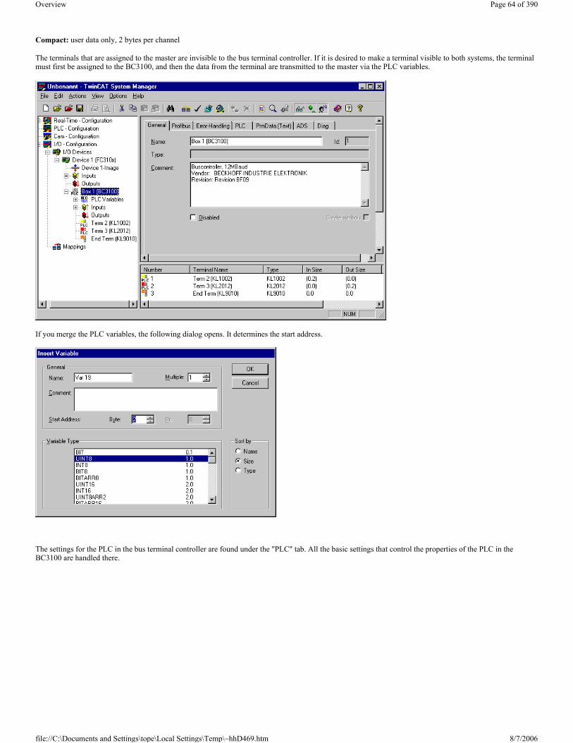
Compact: user data only, 2 bytes per channel
The terminals that are assigned to the master are invisible to the bus terminal controller. If it is desired to make a terminal visible to both systems, the terminal must first be assigned to the BC3100, and then the data from the terminal are transmitted to the master via the PLC variables.
If you merge the PLC variables, the following dialog opens. It determines the start address.
The settings for the PLC in the bus terminal controller are found under the "PLC" tab. All the basic settings that control the properties of the PLC in the BC3100 are handled there.
Page 64 of 390Overview
8/7/2006file://C:\Documents and Settings\tope\Local Settings\Temp\~hhD469.htm

PLC Cycle Time
The PLC cycle time determines the program's repetition frequency. This time is not deterministic. This means that when the program in the bus terminal controller needs more time, the PLC cycle time rises. If the program needs less than the cycle time, it is repeated at intervals of the set cycle time.The processing of the Lightbus and the serial interfaces is executed in the background time. This should be set to approx. 20 % of the PLC cycle time.
The "mean cycle time" is measured in order to optimise the system. You will find this item in PLC Control under Online\Coupler. About 20% - 30% is added to this, and the result entered as the PLC cycle time. The background time is then set to 20% of the PLC cycle time.
PLC cycle time = mean cycle time + 20% = 10 ms + 20% = 12 ms Background time = PLC cycle time * 0,2 = 12 ms * 0,2 = 2,4 ms " 2 ms
Mean cycle time
The measured cycle time also includes that required for the terminal bus update. This results in a connection between the number of terminals that are inserted and the cycle time. Before initiating the program, the bus terminal controller executes a terminal bus update, in order to interrogate the inputs. After the program has been executed, the BC3100 carries out another terminal bus update, in order to write the current outputs. The background time follows this. The cycle time can also be shortened, if the terminal bus update is carried out simultaneously for inputs and outputs (see Terminal Bus Update).
PLC Variables
PLC variables are variables that are situated in the BC3100 from addresses %IB128 and %QB128. This offset can be shifted. These addresses are not assigned to any terminal, so that signals or data can be transmitted to or received from the master via the PLC variables.
Remanent Variables
Retained or remanent variables are data that retain their value when voltage is not present. In PLC Control this data is placed in the allocated flags area. Following the default setting, this means that all the variables from %MB0 - %MB63 are RETAIN data. The maximum setting is 512 bytes
Page 65 of 390Overview
8/7/2006file://C:\Documents and Settings\tope\Local Settings\Temp\~hhD469.htm

Terminal Bus (K-Bus) Update
Double Cycle: Terminal bus inputs before the PLC cycleTerminal bus outputs after the PLC cycle
Before PLC: Terminal bus inputs and outputs before the PLC cycle
After PLC: Terminal bus inputs and outputs after the PLC cycle
Program download via the fibre optic ring TwinCAT offers a facility for transferring the program to the BC3100 over the optical fibre ring. To do this, string communication and the Ams/Ads must be activated in the system manager under the ADS/AMS tab. The TwinCAT system is started after the configuration has been saved. Now the BC3100 target system can be selected in PLC Control.
Thus the PLC tab changes as follows:
If the program is larger, AMS Response during download must be selected.
After saving the configuration you can start the TwinCAT System. In the PLC Control it´s now possible to select the target system of the BC3100.
Selection of the target platform
When TwinCAT PLC Control is restarted, the program asks for the target platform, i.e. the device on which the user will want his program to run. TwinCAT offers two target platforms, the PC as a controller and the BC3100 coupler. For the program transfer with the bus terminal controller there are again two possibilities. "AMS" is for communication over the fieldbus, while the "serial" communication takes place via the PC's serial interface and the BC3100 programming interface. (Zu öffnen unter dem Karteireiter Resourcen -> Steuerungskonfiguration)
Page 66 of 390Overview
8/7/2006file://C:\Documents and Settings\tope\Local Settings\Temp\~hhD469.htm

Selection of the target system
Once the program has been written, the target system is selected under the "Online" symbol bar. In this example, the FC310x with the Box1 and the Run-Time1 of the bus terminal controller.
Program download via the RS232 interface Every bus terminal controller offers the possibility of being programmed via the PC's RS232 interface. This can be implemented with the aid of a special cable (included when TwinCAT BC is supplied). For this purpose, the serial interface is selected in PLC Control
Communication parameters
The settings for the serial interface, port number, baud rate etc. are found under Online/Communication parameters in PLC Control. The bus terminal controller requires the following setting:
Baud rate: 19200
Stop bits: 1
Parity: even
Mappings The Variable Links created for the various Process Images can be controlled afterwards in a graphical display. See the rubric Assignments beneath I/O Configurations.
Context Menu
Right click on Mappings to display its context menu. If you select the ”Generate Mappings” entry, the copy actions between the configured tasks and devices
TwinCAT System Manager: I/O - Configuration
Page 67 of 390Overview
8/7/2006file://C:\Documents and Settings\tope\Local Settings\Temp\~hhD469.htm

will be recalculated.
Generate Mappings
On the right-hand side the corresponding dialogue for the generated mappings will appear as shown below. Select a device mapping to view its cross-reference lists.
Settings options in the cross-referencing dialogue
Address A
Shows the addresses of the linked variables of the process image A. In the case of PLC tasks (as in the example of the RunningSystem PLC project task standard) these are the addresses at which the variables were located at %I... / %Q... Select this option to display the Address column in the list. Click on the column header to display the variables sorted by their addresses (ascending or descending order).
Address B
Shows the addresses within process image B. Process image B can be a task for physical I/Os (the example shows a task for updating a C1220 card) or another linked task within the system configuration.
Type(s)
Displays/removes the Data Type information column.
Size(s)
Displays/removes the byte size information column for the current data type.
Swap Images
Swaps process image A and B in the list.
Auto Column Width
Adapts column width automatically to accommodate long variable names.
Long Names
Shows the linked target variable in its own column with detailed information (coupler name, terminal name..).
Page 68 of 390Overview
8/7/2006file://C:\Documents and Settings\tope\Local Settings\Temp\~hhD469.htm

Context Menu
Right click the mouse in the list window to display the context menu for the documentation functions.
Print List
Outputs the list with all displayed information to the installed printer. For further documentation functions see: Extended Link Options.
Copy List
Copies the list to the clipboard.
Export List
Exports the variable list in *.csv file format (comma separated values), for further processing (e.g. with a spreadsheet program, etc.).
Export Mapping Info
This Mappings context menu entry calls up a file selection box which is used to save link information for the current System Manager project (XML text file).
You can import this file at a later date to restore the previous links in the event of configuration changes or loss of mapping information. Variable names do not need to be changed in this case. If you wish to save the link information of a selected mapping, select the corresponding assignment on the left in the tree view.
For further information on task/device assignments see: Process Images. Describes, amongst other things, the graphical display of links.
Mapping Types and Graphical Display A list of all process image links is given under Mappings.
TwinCAT System Manager: I/O - Configuration
Page 69 of 390Overview
8/7/2006file://C:\Documents and Settings\tope\Local Settings\Temp\~hhD469.htm

On the right-hand side the corresponding dialogue for the selected assignments will appear as shown below.
Map ID
Identification number for internal management of the various Mappings.
Map Name
Names both linked process images.
Map Type
Synchronous: A process image is master, second slave. The master actuates the outputs for writing (e.g. to fieldbus card C1220, ..) and checks that the other side has completed its I/O cycle in order to read the current inputs. The other side has no independent cycle time in this case (Engl. timekeeper).
Asynchronous: Is set, e.g. in the event of links from two tasks, or with devices operating on their own cycle times (e.g. COM port) and independently regulates and thereby the refreshes inputs and outputs. The exchange of information between two Process Images thereby takes place in the case of asynchronous mapping on the basis of the three-buffer principle.
For some device types (e.g. the multitasking Profibus card FC310x) a mix of synchronous and asynchronous assignment (mappings) is used. In relation to the device the higher Priority task behaves in a synchronous manner while the lower priority task is asynchronous.
Watchdog
In the case of asynchronous mapping (see Map Type) a task could fail to conclude correctly (endless loop), the other task is, however, processed as normal and therefore continues to read old values from the buffers. A maximum lifecycle value is specified to prevent this occurring. Once the value is reached, all buffer values are reset to ‘0’.
Timing
Activates the timing of a synchronous assignment (see Map Type).
Process Image A
Shows the task name assigned to process image A.
Process image B
Shows the task name assigned to process image B.
Show A -> B and/or B -> A
Exchanges the direction of both process images in the displayed view.
Page 70 of 390Overview
8/7/2006file://C:\Documents and Settings\tope\Local Settings\Temp\~hhD469.htm

The colours green and pink represent process images A and B. The colours yellow and blue are in/outputs of the process image. Click with the mouse on the in/outputs to display a tool tip with the variable terminal names.
Context Menu
A right mouse click displays the context menu via which you can set the zoom resolution of the mappings graphics. The higher the pixel value per byte, the easier it is to assess the links for individual variables.
Dialogues "A -> B" and/or "B -> A"
Number
Current Copy Action Number.
Offset A
Gives the offset within process image A, from which the copy action is actuated.
Offset B
Gives the offset within process image A, from which the copy action is actuated.
Size
Length of the values to be copied from each offset (e.g. 0.1 means that one bit is copied).
Page 71 of 390Overview
8/7/2006file://C:\Documents and Settings\tope\Local Settings\Temp\~hhD469.htm

"Online" Tab
When a configuration is active on a running system, you will find a graphical display of the copy times between the different process images. The given information on the online graph differs depending on a synchronous or asynchronous mapping (see also: Map Type).
Asynchronous mapping:
The time presented next to
A: A->B references the copying of all data of this mapping for process image A into buffer of process image B.
A: B->A references the copying of all data of this mapping for process image A from buffer of process image B.
B: A->B references the copying of all data of this mapping from process image B out of the buffer from process image A.
B: B->A references the copying of all data of this mapping from process image B into the buffer for process image A.
Synchronous mapping:
The time presented next to
A->B references the copying of all data of this mapping for process image A to B.
B->A references the copying of all data of this mapping for process image A from B.
GetIoState references the duration of the function GetIoState(), which depends on the used fieldbus master card.
StartIo references the duration of the function StartIo(), which starts the fieldbus and depends on the used fieldbus master card.
Note:
All given values are time distances between start and finishing of the referenced action and can fluctuate due to interruptions from higher priority tasks.
Additional infos about the History View can be found under: Settings for History View.
Busy counter
At synchronous mappings of process images, the master process image checks whether the slave has completed its I/O cycle and offers new inputs for
Page 72 of 390Overview
8/7/2006file://C:\Documents and Settings\tope\Local Settings\Temp\~hhD469.htm

transmission. If transmission does not take place, the Busy Counter is incremented by the master. At asynchronous mappings, the "Busy counter" field is disabled.
Reset
Resets the Busy counter to ‘0’.
Overview
Beckhoff C1220/FC200x/CX1500-M200 The C1220 is an active ISA master card for the Beckhoff Lightbus. Up to 254 Lightbus nodes ("Boxes") can be connected into a ring circuit. Individual boxes and sometimes separate I/O data boxes can be updated selectively and on a priority basis (Beckhoff CDL concept).
The DPRAM of the C1220 is 4 kBytes. There are no interrupts used.
The FC2001 and FC2002 are PCI bus cards which are otherwise no different from the C1220. The FC2002 supports two independent Lightbus rings (works like two independent C1220/FC2001 cards).
The CX1500-M200 is a Beckhoff Lightbus Master interface for the CX1000 Embedded-PC series. Again, from the functional standpoint a CX1500-M200 doesn't differ from a C1220 card.
Context menu
Append Box... <Insert>
Adds Beckhoff Lightbus boxes to the configuration. The order must correspond with the physical order inside the fiber-optic ring! For a list of all currently supported Beckhoff Lightbus devices, see "Lightbus - Overview" page.
Delete Device... <Del>
TwinCAT System Manager: Reference
Supported I/O Devices (Fieldbus cards, Ethernet, USB, Miscellaneous ...) TwinCAT 2.8 TwinCAT 2.9
TwinCAT System Manager: Reference
Page 73 of 390Overview
8/7/2006file://C:\Documents and Settings\tope\Local Settings\Temp\~hhD469.htm

Removes the C1220 fieldbus card and all subsidiary elements from the I/O configuration.
Online Reset
Initiates an online reset on the fibreoptic ring.
Break Location Test
Initiates a ring break test on the fibreoptic ring. This Lightbus-specific feature brings up the "Box" position, the fiber-optical ring is currently interrupted.
Export Device
Exports all device settings made at this Lightbus device into a file (*.tce), including eventually available mapping informations with Diagnosis Inputs,
Import Box
Imports formerly saved node ("Box") configurations, including attached Bus Terminals and available variable links, if wanted.
Scan Boxes
Scans the ring for deployed Lightbus nodes (including attached Bus Terminals).
”C1220”, "FC200x" or "CX1500-M200" Tab
Address: For offline configuration, enter the appropriate DPRAM card address here.
Hint: Under TwinCAT 2.9, if the active target system is in "Config Mode", the online feature "Scan Devices.." will find the Lightbus interface card(s) and its address(es) automatically!
For C1220 only: This address is jumped on the card and can be set to the following (jumper settings J1 - J6):
� 0xC8000 00 1000 � 0xD0000 01 0100 (Standard) � 0xD8000 10 0010 � 0xE0000 11 0001
Hint: At CX1500-M200 interfaces, the appropriate address belongs to the manufacturer settings!
PCI Slot/Ring: (FC2001/FC2002) Gives the logical PCI slot and in addition for FC2002 whether ring A or ring B is here in use, as info.
Search: Searches the computer for C1220 and/or FC2001/FC2002 and sets the address/slot number correspondingly.
Check number of boxes: If you tick this checkbox, when the card is initialised the number of boxes which are physically present is compared with the number entered under this card in the System Manager. If the numbers do not comply an error is triggered.
System Start Despite Optical Fibre Error: A warning is given rather than halting the TwinCAT start process.
Page 74 of 390Overview
8/7/2006file://C:\Documents and Settings\tope\Local Settings\Temp\~hhD469.htm

K-Bus Update with Broadcast Telegram (0x80): Decides whether K-Bus update should take place individually per Bus Coupler or for all Bus Couplers together via broadcast telegram when Bus Couplers are connected.
Reserved CDL’s: The C1220 has eight priority channels (CDLs) which, under normal circumstances, are also used by the System Manager. If individual CDL’s are unused - in non-standard applications - these must be indicated here.
Firmware: Displays the firmware version of a found Beckhoff Lightbus interface card (for older C1220s ”Found” only).
Bus Utilization (%): Displays the estimated total utilization of the bus bandwith (the total of all used CDLs). Upon the displayed value, it has to be decided whether balancing the bus load onto another Lightbus ring could be necessary.
”(Online) DPRAM” Tab
See ”Online Display of DPRAM”
”CDL” Tab
See ”CDL Configuration” .
Diagnosis Inputs
The C1220 as well as the FC2001, FC2002 and CX1500-M200 show up in the System Manager with below described diagnosis and control outputs for the status of the fiber optical ring and the Lightbus interface card itself.
Variable DescriptionDeviceState General status, assumes values 0 (o.k.) and 1 (error) onlyDeviceIioFunc Number of function at which error occurred (see C1220 manual also)DeviceIioFuncArg Function argument (see C1220 manual also)BoxWithError Number of box at which error has occurred
ErrorCounter
General Error Counter (DPRAM offset 0xEE0)
The Lightbus interface card has several error counters implemented for detection of I/O problems. These counters are accessible from DPRAM starting at offset 0xEE0 as 16-bit values. There is no overflow handling or reset of these counters implemented by the C1220/FC200x firmware. The counter, who reflects the errors detected by the internal address check (0xEEA) doesn't increment the ErrorCounter.
ErrCntRec1
Error detected by Receiver 1
Received address and/or control bytes unequal the corresponding sent bytes. Receiver 1 alternates with Receiver 2 to compensate the execution time spend for the handling of the interrupt service routines (ISR). ErrCntRec1 and ErrCntRec2 both increment the sum ErrorCounter (see above)
ErrCntRec2Error detected by Receiver 2
Received address and/or control bytes unequal the corresponding sent bytes. Receiver 2 alternates with Receiver 1 to compensate the execution time spend for the handling of the interrupt
Page 75 of 390Overview
8/7/2006file://C:\Documents and Settings\tope\Local Settings\Temp\~hhD469.htm
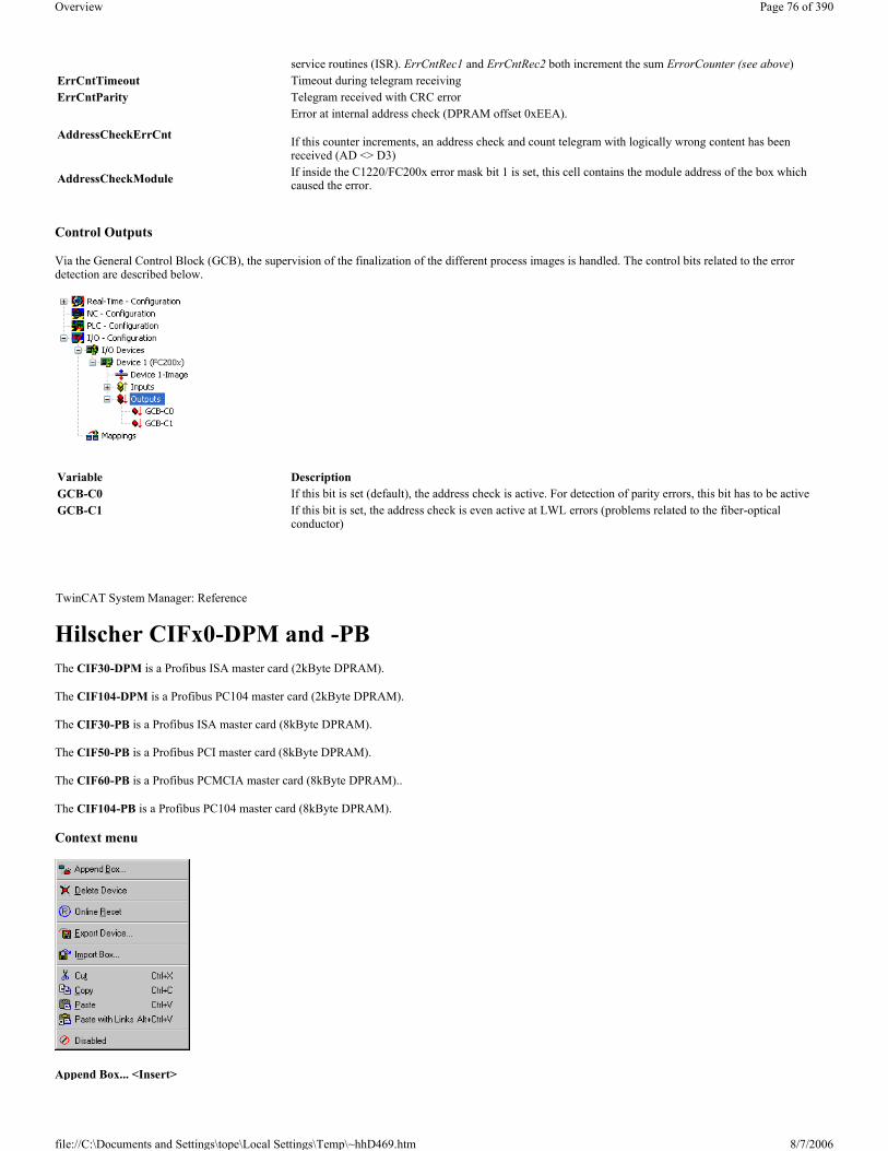
Control Outputs
Via the General Control Block (GCB), the supervision of the finalization of the different process images is handled. The control bits related to the error detection are described below.
Hilscher CIFx0-DPM and -PB The CIF30-DPM is a Profibus ISA master card (2kByte DPRAM).
The CIF104-DPM is a Profibus PC104 master card (2kByte DPRAM).
The CIF30-PB is a Profibus ISA master card (8kByte DPRAM).
The CIF50-PB is a Profibus PCI master card (8kByte DPRAM).
The CIF60-PB is a Profibus PCMCIA master card (8kByte DPRAM)..
The CIF104-PB is a Profibus PC104 master card (8kByte DPRAM).
Context menu
Append Box... <Insert>
service routines (ISR). ErrCntRec1 and ErrCntRec2 both increment the sum ErrorCounter (see above)ErrCntTimeout Timeout during telegram receivingErrCntParity Telegram received with CRC error
AddressCheckErrCnt
Error at internal address check (DPRAM offset 0xEEA).
If this counter increments, an address check and count telegram with logically wrong content has been received (AD <> D3)
AddressCheckModule If inside the C1220/FC200x error mask bit 1 is set, this cell contains the module address of the box which caused the error.
Variable DescriptionGCB-C0 If this bit is set (default), the address check is active. For detection of parity errors, this bit has to be active GCB-C1 If this bit is set, the address check is even active at LWL errors (problems related to the fiber-optical
conductor)
TwinCAT System Manager: Reference
Page 76 of 390Overview
8/7/2006file://C:\Documents and Settings\tope\Local Settings\Temp\~hhD469.htm
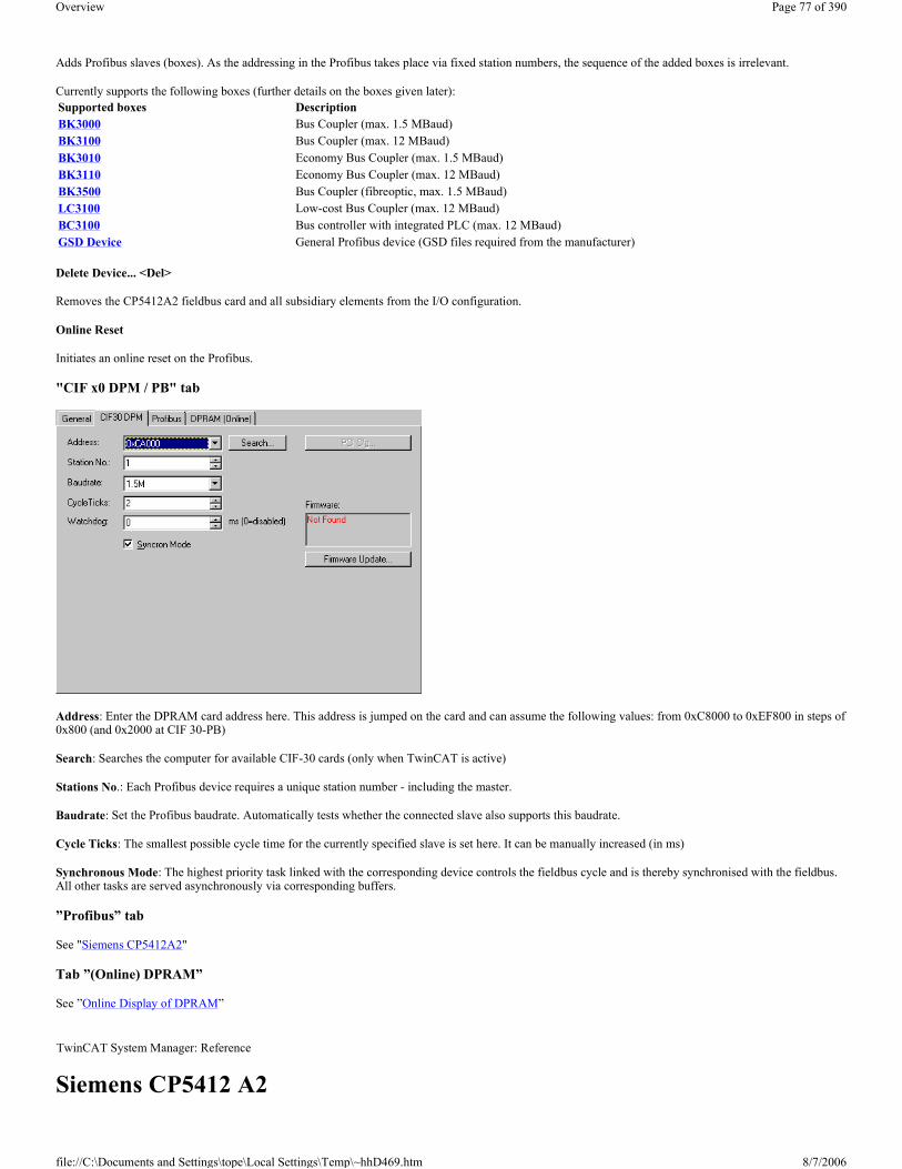
Adds Profibus slaves (boxes). As the addressing in the Profibus takes place via fixed station numbers, the sequence of the added boxes is irrelevant.
Currently supports the following boxes (further details on the boxes given later):
Delete Device... <Del>
Removes the CP5412A2 fieldbus card and all subsidiary elements from the I/O configuration.
Online Reset
Initiates an online reset on the Profibus.
"CIF x0 DPM / PB" tab
Address: Enter the DPRAM card address here. This address is jumped on the card and can assume the following values: from 0xC8000 to 0xEF800 in steps of 0x800 (and 0x2000 at CIF 30-PB)
Search: Searches the computer for available CIF-30 cards (only when TwinCAT is active)
Stations No.: Each Profibus device requires a unique station number - including the master.
Baudrate: Set the Profibus baudrate. Automatically tests whether the connected slave also supports this baudrate.
Cycle Ticks: The smallest possible cycle time for the currently specified slave is set here. It can be manually increased (in ms)
Synchronous Mode: The highest priority task linked with the corresponding device controls the fieldbus cycle and is thereby synchronised with the fieldbus. All other tasks are served asynchronously via corresponding buffers.
”Profibus” tab
See "Siemens CP5412A2"
Tab ”(Online) DPRAM”
See ”Online Display of DPRAM”
Siemens CP5412 A2
Supported boxes DescriptionBK3000 Bus Coupler (max. 1.5 MBaud)BK3100 Bus Coupler (max. 12 MBaud)BK3010 Economy Bus Coupler (max. 1.5 MBaud)BK3110 Economy Bus Coupler (max. 12 MBaud)BK3500 Bus Coupler (fibreoptic, max. 1.5 MBaud)LC3100 Low-cost Bus Coupler (max. 12 MBaud)BC3100 Bus controller with integrated PLC (max. 12 MBaud)GSD Device General Profibus device (GSD files required from the manufacturer)
TwinCAT System Manager: Reference
Page 77 of 390Overview
8/7/2006file://C:\Documents and Settings\tope\Local Settings\Temp\~hhD469.htm

The DPRAM of the CP5412A2 is 16 or 64 Kbytes. There are no interrupts used. There are no functional differences between the 16k and 64k settings. In general therefore the 16k setting is recommended.
Context menu
Append Box... <Insert>
Adds Profibus slaves (boxes). As the addressing in the Profibus takes place via fixed station numbers, the sequence of the added boxes is irrelevant.
Currently supports the following boxes (further details on the boxes given later):
Delete Device... <Del>
Removes the CP5412A2 fieldbus card and all subsidiary elements from the I/O configuration.
Online Reset
Initiates an online reset on the Profibus.
”CP 5412” tab
Address: The DPRAM card address is entered here. The software sets this address when the card is initialised.
Note:
For newer motherboards/BIOS it may be necessary to reserve the DPRAM area which the card will use in the computer BIOS. The corresponding setting is generally carried out in PNP-BIOS and is described as ISA Memblock.
16 / 64 Kbytes: Set here whether the card should use 16 or 64 Kbytes of DPRAM. There are no functional differences between the 16k and 64k settings. In general therefore the 16k setting is recommended.
Port: Used to set the port address for the card, which is set on the card via the DIL switch. When the card is initialised the DPRAM address specified above is set via the port. Available ports (in hex) (the corresponding DIL switches 1-4) are:
� 240 -243 0000 (Standard) � 244-247 0001
Supported boxes DescriptionBK3000 Bus Coupler (max. 1.5 MBaud)BK3100 Bus Coupler (max. 12 MBaud)BK3010 Economy Bus Coupler (max. 1.5 MBaud)BK3110 Economy Bus Coupler (max. 12 MBaud)BK3500 Bus Coupler (fibreoptic, max. 1.5 MBaud)LC3100 Low-cost Bus Coupler (max. 12 MBaud)BC3100 Bus controller with integrated PLC (max. 12 MBaud)GSD Device General Profibus device (GSD files required from the manufacturer)
Page 78 of 390Overview
8/7/2006file://C:\Documents and Settings\tope\Local Settings\Temp\~hhD469.htm

� 248-24B 0010 � 24C-24F 0011 � 280-283 0100 � 284-287 0101 � 288-28B 0110 � 28C-28F 0111 � 300-303 1000 � 304-307 1001 � 308-30B 1010 � 30C-30F 1011 � 390-393 1100 � 394-397 1101 � 398-39B 1110 � 39C-39F 1111
Stations No.: Each Profibus device requires a unique station number. - including the master.
Baudrate: Set the Profibus baudrate. Automatically tests whether the connected slave also supports this baudrate.
Cycle Ticks: The smallest possible cycle time for the currently specified slave is set here. It can be manually increased (in ms)
Synchronous Mode: The highest priority task linked with the corresponding device controls the fieldbus cycle and is thereby synchronised with the fieldbus. All other tasks are served asynchronously via corresponding buffers.
”Profibus” tab
The parameters set here are described in the PROFIBUS standard (DIN 19245 part 3 - PROFIBUS-DP), Chapter 7 and should only be changed by expert users.
Tab ”(Online) DPRAM”
See ”Online Display of DPRAM” .
Input Diagnosis
The Siemens CP5412A2 automatically provides two input bytes, which describe the status of the card and the Profibus:
DeviceState: General status, which only assumes values 0=OK and 1=error
DeviceDpState: DeviceDpState is a flag byte, the individual bits have the following definitions:
0x00 = No error
0x01 = Transmitter fault
0x02 = Master address fault
Page 79 of 390Overview
8/7/2006file://C:\Documents and Settings\tope\Local Settings\Temp\~hhD469.htm

0x04 = HSA fault
0x08 = Baudrate fault
0x80 = Temp fault
Note
If the CP5412A2 in a Beckhoff IPC is set at 24V UPS and/or with special keys, the port address must be changed from 0x240 to another value as 0x240 is configured by the IPC.
Siemens IM182 - Profibus Slave The TwinCAT system can be used as a slave in a Profibus with the aid of the Profibus DP - slave fieldbus card. The DPRAM is 1536 (0x600) bytes. There are no interrupts used.
Context menu
Delete Device... <Del>
Removes the IM182 fieldbus card from the I/O configuration.
Online Reset
Initiates an online reset on the Profibus.
"SPC3 / IM182" tab
Address: Enter the DPRAM card address here. This address is jumped on the card
Port: The card uses one of the ports 0x320 or 0x330
Stations No.: Each Profibus device requires a unique station number.
Tab ”(Online) DPRAM”
See ”Online Display of DPRAM”
Input Diagnosis
The Siemens SPC3/IM182 automatically provides one input byte which describes the status of the card and the Profibus:
Flags: The individual bits have the following definitions:
TwinCAT System Manager: Reference
Page 80 of 390Overview
8/7/2006file://C:\Documents and Settings\tope\Local Settings\Temp\~hhD469.htm

� 0x01 = NEW_OUTPUTS � 0x02 = CLEAR_MODE � 0x04 = NO_DATA_EXCH � 0x08 = BAUD_SEARCHING � 0x10 = SYNC_MODE � 0x20 = FREEZE_MODE
Variables can be defined under the inputs and outputs for data exchange with a Profibus master. These variables are exchanged with the Profibus master and can be linked within TwinCAT. Variables are added as described in ”Additional Tasks” under ”Adding Variables”
Hilscher CIFxx-IBM The CIF30-IBM is an Interbus ISA master card.
The CIF50-IBM is an Interbus PCI master card.
The CIF60-IBM is an Interbus PCMIA master card.
The C104-IBM is an Interbus PC104 master card.
The CIFx0-IBM DPRAM is 2 Kbytes (CIF60-IBM 8 Kbytes). There are no interrupts used.
The following description relates to the CIF30-IBM. The other cards vary from the point of view of TwinCAT in form only.
Context menu
Append Box... <Insert>
Adds InterBus nodes ("boxes"). For an Overview of all currently supported Interbus devices, please see...
Delete Device... <Del>
Removes the CIF40-IBSM fieldbus card and all subsidiary elements from the I/O configuration.
Online Reset
Initiates an online reset on the InterBus-S.
"CIF-x0 IBM" tab
Address: Enter the DPRAM card address here. This address is jumped on the card and can assume the following values: from 0xC8000 to 0xEF800 in steps of
TwinCAT System Manager: Reference
Page 81 of 390Overview
8/7/2006file://C:\Documents and Settings\tope\Local Settings\Temp\~hhD469.htm
0x800
Search: Searches the computer for available CIF-40 cards (only when TwinCAT is active)
Cycle Ticks: Used to set the cycle time with which the InterBus-S should be served (in ms)
Synchronous Mode: The highest priority task linked with the corresponding device controls the fieldbus cycle and is thereby synchronised with the fieldbus. All other tasks are served asynchronously via corresponding buffers.
Read Config: Activates loading of current Interbus device configuration, provided that a TwinCAT configuration is started in which no devices have been configured under the Interbus master card!
� Up to TwinCAT 2.9 Build <= 1000: After TwinCAT-Start the ”Read Bus Configuration” button is enabled. � Since TwinCAT 2.9 Build > 1000: Start TwinCAT system in config mode. Select "Reload I/O Devices" and "Scan Sub Devices".
Tab ”(Online) DPRAM”
See ”Online Display of DPRAM”
Input Diagnosis
The CIF-40 automatically provides two input bytes which describe the status of the card and the Interbus:
GlobalFlags: The individual bits have the following definitions:
� 0x01 = Ctrl: Parameterisation error � 0x02 = W1Err: At least one faulty W1 interface � 0x04 = W2Err: At least one faulty W2 interface � 0x08 = SysErr: System error occurred � 0x10 = Mod: At least one slave registering module error � 0x20 = Rec: At least one slave requires reconfiguration
EventError: This value is dependent upon the GlobalFlags:
In the case of W1Err, W2Err, Mod or Rec the number of the affected slaves is displayed. The following conditions apply otherwise:
= 101, SysErr difference between configuration list and structure present = 103, SysErr network change during bus operation = 104, SysErr multiple data cycle error = 105, SysErr time monitoring error = 106, SysErr un-locatable network error = 108, SysErr no network connection = 170, Ctrl communication was not initialised = 171, Ctrl too many modules (> 112) parameterised = 172, Ctrl more modules connected than parameterised = 173, Ctrl fewer modules connected than parameterised = 174, Ctrl unsupported length code = 175, Ctrl incorrectly parameterised length code = 176, Ctrl incorrectly parameterised identity code = 177, Ctrl incorrectly parameterised installation depth = 178, SysErr user program-served watchdog out of configured time = 180, Ctrl unknown operating mode = 181, SysErr user program did not acknowledge data cycle
Hilscher CIF40-IBSM The CIF40-IBM is an InterBus-S master card. The DPRAM of the CIF40-IBSM is 2 Kbytes. There are no interrupts used.
Context menu
TwinCAT System Manager: Reference
Page 82 of 390Overview
8/7/2006file://C:\Documents and Settings\tope\Local Settings\Temp\~hhD469.htm

Append Box... <Insert>
Adds InterBus nodes ("boxes"). For an Overview of all currently supported Interbus devices, please see...
Delete Device... <Del>
Removes the CIF40-IBSM fieldbus card and all subsidiary elements from the I/O configuration.
Online Reset
Initiates an online reset on the InterBus-S.
"CIF-40 IBSM" tab
Address: Enter the DPRAM card address here. This address is jumped on the card and can assume the following values: from 0xC8000 to 0xEF800 in steps of 0x800
Search: Searches the computer for available CIF-40 cards (only when TwinCAT is active)
Cycle Ticks: Used to set the cycle time with which the InterBus-S should be served (in ms)
Synchronous Mode: The highest priority task linked with the corresponding device controls the fieldbus cycle and is thereby synchronised with the fieldbus. All other tasks are served asynchronously via corresponding buffers.
Tab ”(Online) DPRAM”
See ”Online Display of DPRAM”
Input Diagnosis
The CIF-40 automatically provides two input bytes which describe the status of the card and the Interbus:
GlobalFlags: The individual bits have the following definitions:
� 0x01 = Ctrl: Parameterisation error � 0x02 = W1Err: At least one faulty W1 interface � 0x04 = W2Err: At least one faulty W2 interface � 0x08 = SysErr: System error occurred � 0x10 = Mod: At least one slave registering module error � 0x20 = Rec: At least one slave requires reconfiguration
EventError: This value is dependent upon the GlobalFlags:
In the case of W1Err, W2Err, Mod or Rec the number of the affected slaves is displayed. The following conditions apply otherwise:
= 101, SysErr difference between configuration list and structure present
Page 83 of 390Overview
8/7/2006file://C:\Documents and Settings\tope\Local Settings\Temp\~hhD469.htm

= 103, SysErr network change during bus operation = 104, SysErr multiple data cycle error = 105, SysErr time monitoring error = 106, SysErr un-locatable network error = 108, SysErr no network connection = 170, Ctrl communication was not initialised = 171, Ctrl too many modules (> 112) parameterised = 172, Ctrl more modules connected than parameterised = 173, Ctrl fewer modules connected than parameterised = 174, Ctrl unsupported length code = 175, Ctrl incorrectly parameterised length code = 176, Ctrl incorrectly parameterised identity code = 177, Ctrl incorrectly parameterised installation depth = 178, SysErr user program-served watchdog out of configured time = 180, Ctrl unknown operating mode = 181, SysErr user program did not acknowledge data cycle
Phoenix IBS SC/I-T and IBS SC/RI/RT-LK The IBS ISA SC-I/T is an InterBus-S master card.
The IBS ISA SC-I/T DPRAM (MPM) is 4 Kbytes. There are no interrupts used.
Context menu
Append Box... <Insert>
Adds InterBus nodes ("boxes"). For an Overview of all currently supported Interbus devices, please see...
Delete Device... <Del>
Removes the IBS ISA SC-I/T fieldbus card and all subsidiary elements from the I/O configuration.
Online Reset
Initiates an online reset on the InterBus-S. The card is then set to RUN mode (see Bus Controller).
"IBS ISA SC-I/T "and "IBS ISA SC/RI/RT-LK" tab
Address: Enter the DPRAM card address here. This address can assume the following values: from 0xC8000 to 0xEF000 in steps of 0x1000
Port: Enter the card port address here. This address is jumped on the card and can assume the following values: from 0x100 to 0x3F8 in steps of 0x8
TwinCAT System Manager: Reference
Page 84 of 390Overview
8/7/2006file://C:\Documents and Settings\tope\Local Settings\Temp\~hhD469.htm

IBS cycle: The run-time of the Interbus is calculated approximately on the basis of the configured devices and displayed.
Synchronous Mode: The highest priority task linked with the corresponding device controls the fieldbus cycle and is thereby synchronised with the fieldbus. All other tasks are served asynchronously via corresponding buffers.
"Activate_Configuration" at StartUp: Activates the loaded configuration during the TwinCAT StartUp phase (standard setting). Can be disabled if other firmware services are to be accessed before StartUp (see System Start with Incomplete Configuration).
"Start_Data_Transfer" at StartUp: Starts cyclical data transfer in the Interbus at the TwinCAT system start.
Read Bus Configuration: Activates loading of current Interbus device configuration, provided that a TwinCAT configuration is started in which no devices have been configured under the Interbus master card!
� Up to TwinCAT 2.9 Build <= 1000: TwinCAT system reports an error message (0 boxes configured and x boxes awaited). The ”Read Bus Configuration” button is then enabled. This will display the previously recognised configuration in the tree.
� Since TwinCAT 2.9 Build > 1000: Start TwinCAT system in config mode. Select "Reload I/O Devices" and "Scan Sub Devices".
Slave Diagnosis: Option available for system coupler only (Masters with slave interface). If seleceted, the process data provides additional two input words: SlaveDiag and SlaveDiagPara.
Read Firmware Version: Reads the firmware version of the card via firmware service "Get_Version_Info" (see card‘s user manual).
NOTE:
For newer motherboards/BIOS it may be necessary to reserve the DPRAM area which the card will use in the computer BIOS. The corresponding setting is generally carried out in PNP-BIOS and is described as ISA Memblock.
”CFG” tab
Lists the configuration framework produced on the basis of the configured devices and which is loaded into the card at the system StartUp. Serves as an overview, particularly when the configuration is to be influenced at the run-time via ADS.
Firmware services
Nearly all SC/I-T firmware services can be accessed via ADS by each TwinCAT program. For this purpose you need to assign an AMS port to the SC/I-T. This port is activated on the ”ADS” tab. The port number is specified as 0x7000 + the ID of the SC/I-T. Otherwise a PLC library is offered which gives the essential Firmware Services for Bus Control in a simple user form.
”ADS” tab
Use AdsReadWriteReq (see ADS documentation) to display the services in the following form:
IndexGroup = 0x00010001
IndexOffset = firmware service code (e.g. 0x00000713 for Control_Active_Configuration)
Page 85 of 390Overview
8/7/2006file://C:\Documents and Settings\tope\Local Settings\Temp\~hhD469.htm

The number of parameters is determined automatically using Write data. The Write data are not converted by the TwinCAT into Motorola format. The user must do this if required.
The result (confirmation) of the firmware service is returned in Read data.
Example: Switching off a device while bus is in operation (see Interbus Box Tab ”CAC/CDF”)
The device with the logical device number 3.1 should be switched off while the bus is in operation:
IndexGroup: 0x00010001
IndexOffset: 0x00000713 (Control_Active_Configuration)
Write Data:
Word 0 0x0200 (device_Off in Motorola Format)
Word 1 0x0100 (entry in Motorola Format)
Word 2 0x0103 (3.1 in Motorola Format)
The Write length is 6 bytes so that the firmware of the Parameter_Count 3 (words) is provided.
Confirmation:
Positive confirmation is as follows:
Read Data:
Word 0 0x0000
Negative confirmation is as follows:
Read Data:
Word 0 0xXXXX (result in Motorola Format)
Word 1 0xXXXX (Add_Err_Info Motorola Format)
”Firmware Commands” tab
Allows typical firmware bus control commands to be triggered via ADS (providing that an ADS port has been selected).
Bus Control
The bus controller can be influenced with the above firmware services as illustrated below:
Page 86 of 390Overview
8/7/2006file://C:\Documents and Settings\tope\Local Settings\Temp\~hhD469.htm

Status indicates the current card status.
� State & 0x00E0 == 0x0080 -> PAR_READY
� State & 0x00E0 == 0x00C0 -> ACTIVE � State & 0x00E0 == 0x00E0 -> RUN
Input Diagnosis
The IBS ISA SC-I/T automatically provides two input words whose bits describe the status of the card and the Interbus:
State: 0x0001 = user error
0x0002 = periphery error
0x0004 = bus error
0x0008 = hardware error(interface module)
0x0010 = diagnostic routine active
0x0020 = data transfer active
0x0040 = selected configuration is ready to operate
0x0080 = interface module is ready to operate
0x0100 = bus segment is switched off
0x0200 = disable command output
0x0400 = standard function negative
0x0800 = synchronisation error occurred
0x1000 = data cycle malfunction
Page 87 of 390Overview
8/7/2006file://C:\Documents and Settings\tope\Local Settings\Temp\~hhD469.htm

0x2000 = pre-set waiting period exceeded
0x4000 = pre-set error density exceeded
0x8000 = signal to controller present
DiagPara: The content depends upon the contents of State.
- If 0x0001 or 0x0008 bit is set, the error code is shown in DiagPara.
- If 0x0002 or 0x0004 bit is set, the segment address of the error location is shown in DiagPara.
See firmware Reference Manual IBS SYS FW G4 LIB UM (item no.: 27 45 13 0) under function GetIBSDiagnostic.
Available only for Masters with slave interface (System coupler).
SlaveState:
0x0001 = Slave data transfer. The slave is in data exchange mode. 0x0002 = Fail. Slave reports modul error.
0x0004 = Slave initialized.
0x0008 = Power on. The external voltage is ok.
0x0010 = Ready. Slave is in READY state.
SlaveDiagPara: The content depends upon the contents of SlaveState.
System StartUp with Incomplete Configuration
If you wish the system to start with incomplete configuration you have several options:
1. Alternative Definition: If the potentially unavailable devices are assigned an alternative, they will be disabled when the system is started (this can only take place if deliberately activated using Control_Active_Configuration (see. "InterBus-S” tab for that device)).
2. Special Device Settings: A Control_Active_Configuration command can be defined for individual devices. This will be executed before activating the configuration (see "InterBus-S Tab” for that device). Note that a Control_Active_Configuration command will affect subsidiary devices!
3. Special configuration during system StartUp by the PLC: You can tell the card to switch on in PAR_READY mode at the system StartUp and have further configuration and bus control carried out by the PLC. In this case proceed as follows:
a. Deselect automatic "Active_Configuration". This will leave the card in PAR_READY state b. After the system start, you can individually deselect those devices which you do not require or use a Group Definition
(Control_Active_Configuration), so that only remaining (present) devices are activated. De-selection (switching off selected devices) is generally carried out from the PLC via ADS. You can link in the PLC library "PlcIbsScit.lib" in order to view the necessary ADS commands in the form of options.
c. Actuate "Active_Configuration" via ADS d. Actuate "Start_Data_Transfer" via ADS
If you later wish to reactivate the inactive devices, use also "Control_Active_Configuration" via ADS when the system is in RUN mode.
ISA IBS SC/RI/RT-LK Slave Interface (System Coupler)
The slave interface is configured by the higher level INTERBUS system. The process data length of the slave interface can be configured, and has a maximum length of 10 words. When the IBS SC/RI/RT-LK is added to the I/O configuration, the process data length of the system coupler is set to 10 words, and the parameter channel data length to 0 bits (no PCP). The INTERBUS interfaces of the IBS SC/RI/RT-LK are translated by a medium converter from copper to optical fibre transmission. The medium converter has ID code 0x08 and length code 0x0. It is added automatically by the System Manager to the card's I/O configuration. Do not initiate operation of the higher level INTERBUS system until the system coupler has the final configuration, since configuration changes will put the higher level system into an error state.
Page 88 of 390Overview
8/7/2006file://C:\Documents and Settings\tope\Local Settings\Temp\~hhD469.htm

The process data length and parameter channel length of the system coupler can be configured via the slave's context menu commands. The slave's context menu can be opened by clicking with the right mouse button on the slave in the tree of I/O devices.
The maximum possible length for the process data channel depends on the length chosen for the parameter channel. The process data length of 10 words can only be configured after the parameter channel has been deactivated. The system coupler's ID code is generated from the chosen length of the parameter channel, and can adopt the following values:
� ID code 3: no PCP, maximum process data length 10 words; � ID code 235: parameter channel length 1 word, maximum process data length 9 words; � ID code 232: parameter channel length 2 words, maximum process data length 8 words; � ID code 233: parameter channel length 4 words, maximum process data length 6 words;
Page 89 of 390Overview
8/7/2006file://C:\Documents and Settings\tope\Local Settings\Temp\~hhD469.htm

The system coupler can be supplied with an external voltage so that data can still continue to be exchanged in the higher level system even if the lower level master fails. The slave's configuration can not be permanently saved on the IBS SC/RI/RT-LK card, and is reset to default values whenever the PC boots again. The card's configuration memory is cleared, and the higher level system reports a peripheral error. In the default configuration, the system coupler has ID code 233 and length code 0x4 (4 words). The parameter channel is 64 bits long.
Configuration of the IBS SC/RI/RT-LK Slave Interfaces in the Higher level INTERBUS System
The system coupler in the higher level system is preceded by a bus terminal with ID code 0x0C and length code 0x0. The system coupler's ID code and length code are specified by the configuration of the system coupler in the lower level system.
Hilscher CIF50-IBS System requirements:
� TwinCAT 2.9 build > 1000 and higher.
The CIF50-IBS is an Interbus-S slave PCI card with 8 kB DPRAM. Supported baud rates: 500kBit and 2MBit. The baud rate can be configured via a DIP switch on the card. The new baud rate will only apply after a system restart (power OFF). The slave card is offered in two versions, i.e. with copper or optical fibre fieldbus interface. TwinCAT configuration is identical in both cases.
"General" tab See "General" tab
"CIF50-IBS" tab
Preserve Database: If this option is selected, the static (FLASH) configuration is not cleared when TwinCAT is started. Default: Not selected.
PCI Bus/Slot: Indicates in which logical PCI slot the card was found.
Search: This option enables any CIF50-IBS cards installed in the computer to be identified.
Firmware Update: Enables a firmware update to be carried out.
Watchdog: Watchdog time in ms. Default: 0 ms (deactivated).
TwinCAT System Manager: Reference
Page 90 of 390Overview
8/7/2006file://C:\Documents and Settings\tope\Local Settings\Temp\~hhD469.htm

Generation of the module error at the Interbus master can be configured via the following options:
Cause Error on Watchdog: The watchdog monitoring should send a module error to the master. The watchdog time has to be set to a value <> 0. After a TwinCAT stop, a module error is sent to the master once the watchdog time has elapsed. Default: Selected.
Cause Error on NOT READY: A module error is sent to the master if the slave is in NOT READY state. During a TwinCAT stop, the slave is set to NOT READY state. Default: Selected.
Cause Error on Init Error: A module error is sent to the master if an error occurs during initialisation. Default: Selected.
Cause Error on Init Command: A module error is sent to the master after an initialisation command. Default: Selected.
The module error enables the master to detect the state of the slave card.
Tab ”(Online) DPRAM" See ”Online Display of DPRAM"
CIF50-IBS diagnostic inputs
The CIF50-IBS automatically has 8 input bytes describing the state of card and the Interbus:
GlobalFlags: The individual bits have the following definitions:
� 0x01 = Bus Active (0 = Bus not active) � 0x02 = Data Exchange Active (0 = No data exchange) � 0x04 = PCP Communication Established (0 = No PCP communication) � 0x08 = Initializaition Error Detected (0 = No initialization fault) � 0x10 = Runtime Error Detected (0 = No runtime error) � 0x20 = Application is in 'NotReady' State (0 = System running)
Via these flags the slave application can detect the state of the InterBus (master). During data exchange with the master, the bits Bus Active and Data Exchange Active are set. If the master is not configured, the bit Application is in 'NotReady' State may be set.
LengthCode: Shows the current length code of the slave module. Default: 21 ( = 10 words input and output process data length).
IdentCode: Shows the current ID code of the slave module. Default: Digital I/O slave ( ID code = 0x03 ).
ErrorCounter: Number of errors detected since the module was switched on.
EventError: Error code of the last detected error. See CIF50-IBS error codes.
AddParam: Additional error code parameters (optional). See CIF50-IBS error codes.
CIF50-IBS slave data (slave process data)
Page 91 of 390Overview
8/7/2006file://C:\Documents and Settings\tope\Local Settings\Temp\~hhD469.htm

The length of the process data can be configured via the "Slave Data" context menu.
"Slave Data" context menu Right-clicking on "Slave Data" in the configuration tree brings up the following menu:
Prozess Data Width: Can be used to configure the length of the slave process data.
PCP Channel: PCP communication is currently not supported.
The following process data lengths can be configured:
Slave length code Real data width of the Slave in Bytes (Words)
Page 92 of 390Overview
8/7/2006file://C:\Documents and Settings\tope\Local Settings\Temp\~hhD469.htm

System behaviour of the CIF50-IBS within a TwinCAT system In order to be able to operate the card as an Interbus-S slave with an Interbus master, it has to be configured (initialised) first. The card configuration can be stored in a static flash or a non-static memory. If present, the static configuration has a higher priority and is loaded first when the power supply is switched on. In order to be able to load a non-static configuration, the existing static configuration has to be deleted first.
Important note:
The static (flash) configuration can only be loaded with the SyCon configuration software. With TwinCAT system manager only the non-static configuration can be loaded. The TwinCAT software will delete any existing static configuration. The slave card retains the non-static configuration only until it is de-energised (e.g. PC switched off and external power supply OFF).
The slave card can additionally be supplied from an external 24V supply. The external power supply can only be used if the additional COP 50-EPS module is connected with the card. The external power supply ensures that the slave card retains its non-static configuration if the PC is switched off. In the event of this power supply also being interrupted and no static configuration being loaded, the card has to be re-configured. A non-configured slave card will report an initialisation error to the master. The master configuration cannot be activated and data exchange cannot be started (the non-initialised slave segment can initially be switched off in the master configuration and subsequently (once initialised) be switched on).
CIF50-IBS error codes The following error description should help to solve problems quickly.
VFD = Virtual Field Device
CRL = Communication Reference List
CR = Communication Reference
OD = Object Description
ID Code = Identification Code
PDU = Process Data Unit
Initialization Errors
1 2 (1)2 4 (2)3 6 (3)4 8 (4)5 10 (5)6 16 (8)7 18 (9)14 12 (6)15 14 (7)21 20 (10)22 24 (12)
TwinCAT System Manager: Reference
Error number Description
0No Error / Success
No error detected (default value)
50
No User Task
The user task could not been found (internal error). Additional Code: 0 (not used)
51
No Global Data
The global data area could not been accessed (internal error). Additional Code: 0 (not used) No PLC Task
Page 93 of 390Overview
8/7/2006file://C:\Documents and Settings\tope\Local Settings\Temp\~hhD469.htm

52The PLC task could not been found (internal error). Additional Code: 0 (not used)
53
Unknown Mode
The detected data exchange mode is not supported. Additional Code: 0 (not used)
54
Invalid Data Length
The detected data length is undefined / reserved. Additional Code: 0 (not used)
55
Length Code Out Of Range
The detected data length code exceed the max. defined value. Additional Code: Detected length code
56
Invalid ID Code
The detected ID code is none of the defined ID codes. Additional Code: Detected ID Code
57
Initializiation Of The CRL Failed
The internal loading procedure for CRL has failed. Additional Code: 0 (not used)
58
No CRL Header Found
The CRL header could not been found. Additional Code: 0 (not used)
59
CRL Not Found
The CRL could not been found. Additional Code: 0 (not used)
60
CRL Termination Failed
The CRL could not been terminated. Additional Code: 0 (not used)
61
Invalid CRL Header
An error detected during scanning the CRL header (global error). Additional Code: 0 (not used)
62
Invalid Communication Reference (® CRL Header)
The detected communication reference is invalid and has set to 0 for CRL header. Additional Code: Detected CR
63
Invalid Size (® CRL Header)
The entry for the 'size' field within the CRL exceed the max. defined value for this entry. Additional Code: Found CRL size entry
64
Acyclic Control Interval (ACI) Out Of Range (® CRL Header)
The value for the ACI exceed the max. value specified for this entry. Additional Code: 0 (not used)
65
Symbol Length Out Of Range (® CRL Header)
The value for the symbol length exceed the max. specified value for this entry (here: 11). Additional Code: Found symbol length entry
66
VFD Pointer Error (® CRL Header)
The VFD pointer is not supported. This value within the CRL header has to be set to 0 (= FALSE). Additional Code: 0 (not used)
67
Invalid CRL (® CRL)
Error detected during scanning the the CRL (global error). Additional Code: 0 (not used)
Page 94 of 390Overview
8/7/2006file://C:\Documents and Settings\tope\Local Settings\Temp\~hhD469.htm

68
CRL Entries Does Not Match (® CRL)
The count of CRLs found does not match the 'size' field of CRL Header. Additional Code: CR of deficient entry
69
Missing CRL Entry (® CRL)
CRL entry could not been found. Additional Code: CR of deficient entry
70
Double Communication Reference Found (® CRL)
At least one communication reference is already in use. Additional Code: CR of deficient entry
71
Communication Reference Out Of Range (® CRL)
The detected communication reference exceed the specified value for this entry (here: max. 3). Additional Code: CR of deficient entry
72
Invalid Remote Address Found (® CRL)
The detected remote address exceed the specified value for this entry (here: max. 62). Additional Code: CR of deficient entry
73
Double Remote Address Found (® CRL)
The detected remote address is already in use. Additional Code: CR of deficient entry
74
Invalid Connection Type Found (® CRL)
The dectected connection type is unsupported; only MMAZ is possible. Additional Code: CR of deficient entry
75
Invalid LLI SAP Found (® CRL)
The detected LLI SAP is not supported. Additional Code: CR of deficient entry
76
Invalid Connection Attribute (® CRL)
The detected connection attribute is unsupported; only CONN_ATTR_D is defined. Additional Code: CR of deficient entry
77
Send/Receive - Conf./Ack. Counter Out Of Range (® CRL)
One of the max. values for Send_Conf, Recveive_Conf, Send_Ack, or Receive_Ack counters is out of range. Additional Code: CR of deficient entry
78
PDU Length Out Of Range (® CRL)
One of the values of the PDU for Req_Len_High, Req_Len_Low, Ind_Len_High, Ind_Len_Low is out of range. Additional Code: CR of deficient entry
79
Unsupported Service Detected (® CRL)
At least one unsupprted service was detected (client and/or server). Additional Code: CR of deficient entry
80
Symbol Length Out Of Range (® CRL)
The value for the symbol length exceed the max. specified value for this entry (here: 11). Additional Code: CR of deficient entry
81
Max. Allowed Object Entry Reached (® OD)
The detected count of objects exceed the max. defined value. Additional Code: 0 (not used)
Invalid Object Description (® OD)
Page 95 of 390Overview
8/7/2006file://C:\Documents and Settings\tope\Local Settings\Temp\~hhD469.htm

Runtime Errors
82Error detected during scanning OD (global error). Additional Code: 0 (not used)
83
Unknown Object Code (® OD)
The detected object code is not one of SIMPLE_VAR or ARRAY Object Code. Additional Code: Object index of deficient entry
84
Object Index Out Of Range (® OD)
The value for the object index exceed the max. specified value for this entry. Additional Code: Object index of deficient entry
85
Double Object Index Detected (® OD)
At least one object index is already in use. Additional Code: Object index of deficient entry
86
Undefined Data Type (® OD)
The detected object data type is unsupported / undefined. Additional Code: Object index of deficient entry
87
Number Of Elements Out Of Range (® OD)
The number of elements does not correspond to the related object Code: for SIMPLE_VAR Object: Nof_Elements = 1, for ARRAY Object: 1 < Nof_Elements < 256 Additional Code: Object index of deficient entry
88
Object Length Out Of Range (® OD)
The object length exceed the max. value specified for data types VISIBLE_STRING and OCTET_STRING, respectively does not correspond to the data types of the other objects. Additional Code: Object index of deficient entry
89 OD Inconsistent
90 .. 99RFU
Reserved for further use
Error number Description
110
Watchdog Failure
A watchdog failure has occur. Additional Code: Data exchange mode
111
No Data Ackknowledge
The user has failed to ackknowleged the data cycle (in data exchange mode 0). Additional Code: Data exchange mode
112
Bus Not Active
The InterBus is NOT_ACTIVE state. Additional Code: 0 (not used)
113
Bus Reset
The InterBus is in RESET state. Additional Code: 0 (not used)
114
Application
An application (USER) error has been detected by the ALI task. Additional Code: One of the error numbers marked with *.
No Bus Communication
Page 96 of 390Overview
8/7/2006file://C:\Documents and Settings\tope\Local Settings\Temp\~hhD469.htm

115 *
The state of the VFD object is not 'Ready For Communication', or the communication state of the InterBus is not 'Active' (i.g., the board is not connected).
116
Negative Read.Confirmation Received
A negative Read.Confirmation has been received from a communi-cation partner. Additional Code: CR of deficient confirmation
117
Negative Write.Confirmation Received
A negative Write.Confirmation has been received from a communi-cation partner. Additional Code: CR of deficient confirmation
118 *Object Non Existent
The task could not find the requested object.
119 *
Client Not Ready
The state of the PCP client is NOT_READY; a request is still active.
119
Client Not Ready
The state of the PCP client is NOT_READY; a request is still active. Additional Code: CR of active request
120
Negative Initiate.Confirmation Received
A negative Initiate.Confirmation is received. Additional Code: CR of deficient confirmation
121 *
Invalid Communication Reference
The task could not find the requested communication reference.
122 *
Request Still Active
A request is queued internally; the request is still active.
123 *
Communication Reference Not Open
The requested communication reference is not open.
124
Nothing to Process
There is no request to process. Additional Code: CR of deficient confirmation
125
Object Attribute Inconsistent
The task has detected an invalid object index for a Read / Write.Request or an invalid data length. Additional Code: Object index of the deficient request
126
Type Conflict
The task has detected an invalid data type for BOOLEAN, respectively for VISIBLE_STRING within a Write.Indication. Additional Code: Object index of the deficient request
127
Invalid PDU Size
The task has detected an invalid PDU size for a Read.Request. Additional Code: Object index of the deficient request
128
Abort.Indication Received
The task has received an Abort.Indication from a communication partner. Additional Code: CR of connection
Reject.Indication Received
Page 97 of 390Overview
8/7/2006file://C:\Documents and Settings\tope\Local Settings\Temp\~hhD469.htm
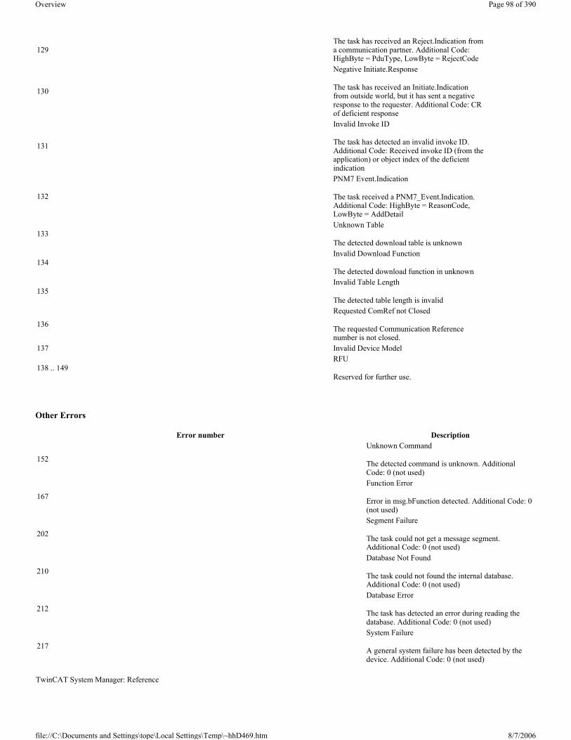
Other Errors
129The task has received an Reject.Indication from a communication partner. Additional Code: HighByte = PduType, LowByte = RejectCode
130
Negative Initiate.Response
The task has received an Initiate.Indication from outside world, but it has sent a negative response to the requester. Additional Code: CR of deficient response
131
Invalid Invoke ID
The task has detected an invalid invoke ID. Additional Code: Received invoke ID (from the application) or object index of the deficient indication
132
PNM7 Event.Indication
The task received a PNM7_Event.Indication. Additional Code: HighByte = ReasonCode, LowByte = AddDetail
133Unknown Table
The detected download table is unknown
134Invalid Download Function
The detected download function in unknown
135Invalid Table Length
The detected table length is invalid
136
Requested ComRef not Closed
The requested Communication Reference number is not closed.
137 Invalid Device Model
138 .. 149RFU
Reserved for further use.
Error number Description
152
Unknown Command
The detected command is unknown. Additional Code: 0 (not used)
167
Function Error
Error in msg.bFunction detected. Additional Code: 0 (not used)
202
Segment Failure
The task could not get a message segment. Additional Code: 0 (not used)
210
Database Not Found
The task could not found the internal database. Additional Code: 0 (not used)
212
Database Error
The task has detected an error during reading the database. Additional Code: 0 (not used)
217
System Failure
A general system failure has been detected by the device. Additional Code: 0 (not used)
TwinCAT System Manager: Reference
Page 98 of 390Overview
8/7/2006file://C:\Documents and Settings\tope\Local Settings\Temp\~hhD469.htm

Beckhoff FC510x The FC510x is a CANopen master card with one (FC5101) or two (FC5102) channels. It supports all CANopen Communication Modes and complies with the CANopen specification DS301V4.01. The card can synchronize the related PLC or NC task using CANopen SYNC. It is a good idea to control drives via the bus in "master" synchronization mode as the SYNC objects are averagely transmitted with quartz precision and the process data exchange is synchronized throughout with the application.
The CANopen master card provides numerous diagnosis possibilities. Emergency objects are stored and can be read via ADS.
The two channel card FC5102 has two independent micro processor systems. Therefore the two channels do not interfere with each other. The CAN interfaces are galvanically isolated (-> hardware description).
Context menu
Append Box... <Insert>
Adds CANopen slaves (boxes). For an Overview of all currently supported CANopen devices, please see...
Delete Device... <Del>
Removes the FC510x fieldbus card and all subsidiary elements from the I/O configuration.
Online Reset
Initiates an online reset on the CANopen bus.
"FC510x" tab
PCI Slot/Irq:
Shows in which logical PCI slot the card was detected and which IRQ is assigned to it. The IRQ is unused.
Master Node Id:
Page 99 of 390Overview
8/7/2006file://C:\Documents and Settings\tope\Local Settings\Temp\~hhD469.htm

Node address for the FC510x. Value range: 1...127. Determines the identifier of the master heartbeat telegram. Ensure that it is not the same as a slave node address.
Baud rate:
Set the Baud rate here. Automatically tests whether the connected slave also supports this baud rate.
Synchronization Mode:
The synchronization mode determines the accuracy of the CANopen SYNC telegram generation.
The highest priority task linked with the FC510x device controls the CANopen card and is thereby synchronized with the fieldbus. All other tasks are served asynchronously via corresponding buffers. For all operating modes you can individually set the communication type for each process data object (PDO) - event driven or synchronized (in each PDO tab). If one of the PDOs has been configured for synchronous operating mode, a SYNC telegram is sent at the start of the cycle, which the slaves use to synchronize their actions with the master cycle.
Depending on the sync accuracy requirements of the application several modes can be selected. Please note, that due to CAN technology a single SYNC telegram may jitter for one entire frame length it the bus is busy at the time of sync generation. The SYNC accuracy therefore refers to the long time stability. Bus nodes that use a phase locked loop (PLL) mechanism to synchronize themselves require a maximum long time stability or accuracy of the SYNC.
Slave
In slave synchronization mode the card receives its time basis from a sync master. The sync master is selected at the corresponding field.
� Sync Master: PC-Task. This is the default setting. The PC provides the time basis using the TwinCAT Real Time. Depending on the settings the Task start (Default with TwinCAT NC) or the Task end (Default at TwinCAT PLC) triggers the SYNC telegram.
� Sync Master: Balanced PC Task. This operating mode as well generated the CANopen Sync cycle with the long term accuracy of the PC time basis. However, the short term accuracy (interval between two SYNC telegrams) is better that with Sync Master "PC-Task": - Run time differences (e.g. caused by case dependent program calls) are leveled out, - the FC510x delays pending transmit telegrams until the SYNC telegram was sent, - the SYNC intervals are determined by the quartz timer of the FC510x card. The card timer is adjusted in small steps to the PC-timer if the difference is larger that the value of the "PLL Sync Time". In this mode the SYNC telegram is delayed for the Shift Time after the end of the TwinCAT task cycle. Here the shift time should be set to a value as small as possible - but large enough to allow the process data access by the TwinCAT task. The function "Calculate Equi-Times" helps to configure the optimal shift time. It is started by selecting the corresponding button.
Page 100 of 390Overview
8/7/2006file://C:\Documents and Settings\tope\Local Settings\Temp\~hhD469.htm

Master
In master synchronization mode the card generates its time basis locally. The SYNC is generated with long time quartz accuracy. The start of the TwinCAT task is triggered by the card, delayed by the Shift Time. In this mode the shift time value should be as large as possible. The function "Calculate Equi-Times" helps to configure the optimal shift time. It is started by selecting the corresponding button.
Cycle Time:
Displays the cycle time of the corresponding highest priority task. The value is updated when the TwinCAT mapping is generated.
Sync-Cycle Multiplier:
CANopen SYNC Cycle Time = (Task) Cycle Time x Sync-Cycle Multiplier. Event driven PDO communications and cyclic synchronized PDO communication are frequently combined when used in conjunction with CANopen. In order to be able to respond rapidly to an event, the TwinCAT task cycle time has to be less than the CANopen SYNC cycle time.
Sync-Cycle time
Shows the cycle time of the CANopen SYNC telegram. This cycle time is derived from the highest priority task which has process data linked to the card, and the Sync Cycle Multiplier.
Sync-Tx-PDO Delay:
Directly after the SYNC telegram, the synchronized slaves send their input data/actual values. The FC510x can delay the sending of the output data / set value (TxPDOs from the perspective of the card) in order to minimize the telegram burst directly after the SYNC. The Sync-Tx-PDO delay parameter is used to set this delay in percent of the Sync Cycle Time.
Example:
Page 101 of 390Overview
8/7/2006file://C:\Documents and Settings\tope\Local Settings\Temp\~hhD469.htm

Task Cycle Time = 2000µs, Sync Cycle Multiplier = 5, Sync Tx-PDO Delay =40[%]. Event driven PDOs can be processed by the PLC task every 2 ms. The CANopen sync cycle is 10 ms, the FC510x sends its synchronized PDOs 4ms (=40% of 10ms) after SYNC.
Search...:
Searches for all connected FC510x channels. Select those required. In the case of an FC5102 both channels A and B appear. These behave in logical terms like two FC5101 cards.
Hardware Configuration …:
In which the address of the FC510x is set in the lower memory area (below 1 MB) of the PC.
Upload Configuration:
Scans the CANopen network and adds all detected equipment to the device (FC510x) (only available when no box has been configured). In the case of Beckhoff boxes, reads the configuration precisely. In the case of external devices, the PDO configuration and the identity object are read and evaluated.
Verify Configuration:
Allows one to compare the expected (configured) network configuration with the actual (physically present) configuration. The data from the CANopen Identity object is read an compared. In the case of Beckhoff Boxes the connected Bus Terminals or Extension Modules are identified ad compared. In preparation.
Firmware:
Shows the current firmware version of the FC510x.
Firmware Update...:
Update the FC510x card firmware version here. Warning: The TwinCAT System must be stopped for this function.
”ADS” tab
The FC510x is an ADS device with its own net ID, which can be changed here. All ADS services (diagnosis, non-cyclical communication) going to the FC510x must address this net ID.
”Box States” tab
Page 102 of 390Overview
8/7/2006file://C:\Documents and Settings\tope\Local Settings\Temp\~hhD469.htm

Displays an overview of all current box statuses.
Tab ”(Online) DPRAM”
See ”Online Display of DPRAM” .
Input Diagnosis
The FC510x automatically provides various diagnostic variables which describe the status of the card and the CANopen network:
cycleCounter: Is incremented at the end of each firmware cycle in order that this variable can indicate whether the last cycle was completed before the task was started.
Error: Shows the number of slaves whose Box State is not equal to zero. Only check the BoxState of the slaves if this value is other than 0.
ActualCycleTime: Shows the current cycle time in 4/25 µs. This variable is only updated when all slaves are involved in the data exchange (and when error is 0)
DiagFlag: Shows whether the diagnostics information on the card has changed. This can be read off using ADS Read. For that purpose, specify the net ID of the FC510x, the port number 200 and the IndexGroup 0xF100. The IndexOffset and the length then relate to the diagnostic data. (Note: The Box States are also available as box variables.)
Offset 1-127: BusStatus List, 1-127 one byte per station address which contains the station status (see BoxState for CANopenboxes)
Global State: Various diagnostic and status displays for the FC510x. The byte in GlobalState(0) shows the status of the card in relation to the TwinCAT system: RUN, RESET, OFFLINE and STOP are distinguished. GlobalState(2) gives information about the status of the CAN controller: "CAN Warning Limit Reached" and "Bus Off" are displayed. Warning limit reached means that the send/receive error counter on the CAN controller has exceeded the value 96. BusOff means that the CAN controller can no longer participate in bus communication; this is caused by an excessive number of CAN errors (Error Frames). In this case there is a serious physical error in the CAN network. (e.g. too little or too much matching resistors, at least a device with an incorrect baudrate, short circuit etc.) The bus off state is only left by a card reset. Details about further global state data, see comments in ”Online” tab.
LastAdsError: Shows the error code of the last ADS access error, e.g. if an attempt has been made to read the diagnostic data for a deactivated node.
CycleFailedCounter: Counts the number of firmware cycles which could not be completed before the associated task wanted to re-read/re-write the process image. If this counter is incremented, the task cycle time has been set too low for the actual network configuration.
BusLoad: Shows the current bus load in %. The Bus Load is an important design criterion for CAN networks. The value shown is a average value over 100ms.
Beckhoff FC510x Hardware Description The FC510x is a CANopen Master card with one (FC5101) or two channels (FC5102). The CAN transceivers are galvanically isolated.
CAN Terminating Resistor
On the card there are CAN terminating resistors (120 Ohms). These can be activated with a jumper (up to hardware version 3) or with a switch (from hardware version 4) close to the CAN connectors.
The Flash Disk Socket is currently not in use.
TwinCAT System Manager: Reference
Page 103 of 390Overview
8/7/2006file://C:\Documents and Settings\tope\Local Settings\Temp\~hhD469.htm

Pin out
The CAN network is connected via 9-pin DB9 sockets with the following pin out:.
The pins not mentioned here are not connected.
Note: An auxiliary power up to 30VDC may be connected to Pin 9 (some CAN Devices use this auxiliary power e.g. for transceiver supply).
LED Behavior
The red ERROR LED and the green RUN help to quickly diagnose the status of the card:
Pin Pin Out2 CAN low (CAN-) 3 CAN Ground (internally connected with Pin 6) 5 Shield6 CAN Ground (internally connected with Pin 3)7 CAN high (CAN+)
Error LED (red) Run LED (green) Description
Page 104 of 390Overview
8/7/2006file://C:\Documents and Settings\tope\Local Settings\Temp\~hhD469.htm

FC510x: Box Diagnosis The CANopen fieldbus card FC510x has a comprehensive range of diagnostic options for connected network nodes.
For each CANopen fieldbus node there is a node state input variable, which signals the status of the current slave during the running time and can be linked, for example with the PLC.
Node State
DiagFlag:
Shows whether the box diagnostic information has changed.
CANopen Emergency Messages
CANopen emergencies and other diagnostic data can be read out via ADS read (new data present as soon as you see the DiagFlag). You need to enter the FC510x ADS net ID. Other ADS parameters:
off off TwinCAT has been stopped
off on All configured bus nodes are error free (Box State=0), TwinCAT Task or Process is running.
off blinking with 2 Hz
The Task, whose process data is linked to the card, is not running. All configured bus nodes have been found and are error free (Box State=0)
blinking with 2Hz onAt least one box state is unequal zero (e.g. node not found, wrong configuration, node in error), TwinCAT Task is running
blinking with 2 Hz off At least one box state is unequal zero (e.g. node not found, wrong configuration, node in error), TwinCAT Task is not running
on off
TwinCAT is running, CAN Controller is "Bus OFF". Physical CAN problem. Possible reasons: e.g. terminating resistor missing, bus too long, wrong baud rate, node address configured twice, short circuit, wiring error.
Restart is necessary blinking with 20Hz blinking with 20Hz Configuration Upload is under wayblinking with 20Hz off card is in STOP mode
TwinCAT System Manager: Reference
Page 105 of 390Overview
8/7/2006file://C:\Documents and Settings\tope\Local Settings\Temp\~hhD469.htm

Port: 200
IndexGroup: Lo-Word = 0xF180, Hi-Word = Node-Number.
IndexOffset: See below
Length: See below
If more than 26 bytes of diagnostic data have been read out the emergency memory is reset.
The diagnostic data have the following definitions:
Hilscher CIFxx-CAN The CIF30-CAN is an CANopen ISA master card.
The CIF50-CAN is an CANopen PCI master card.
The CIF60-CAN is an CANopen PCMCIA master card.
The C104-CAN is an CANopen PC104 master card.
The DPRAM of the CIFx0-CAN is 8 Kbytes. There are no interrupts used.
The following description relates to the CIF30-CAN. The other cards vary from the point of view of TwinCAT in form only.
Offset 0,1: Bit 1: Boot up message not received or incorrectBit 2: Emergency-OverflowBit 0, Bit 3-15: reserved
Offset 2,3: Bits 0-14: TX-PDO (i+1) receivedBit 15: All TX PDOs 16-n received
Offset 4,5: Bits 0-4: 1: Incorrect TX PDO length2: Synchronous TX PDO absent3: Node signalling PRE-OPERATIONAL4: Event timer timed out for TX PDO 5: No response and guarding is activated6: Toggling missed several times and guarding activated
Bits 5-15: Associated COB IDOffset 6: Bits 0-7: 1: Incorrect value during SDO upload
2: Incorrect length during SDO upload3: Abort during SDO up/download4: Incorrect date during a boot-up message5: Timeout while waiting for a boot-up message
Offset 7: Bits 0-7: 2: Incorrect SDO command specifier3: SDO toggle bit has not changed4: SDO length too great5: SDO-Abort6: SDO-Timeout
Offset 8,9 Bits 0-7: SDO up/download indexOffset 10: Bits 0-7: SDO up/download sub-indexOffset 11: Bits 0-7: reservedOffset 12: Bits 0-7: Abort errorClassOffset 13: Bits 0-7: Abort errorCodeOffset 14,15: Bits 0-15: Abort additionalCode
Offset 16-19: Read value (if offset 6 = 1)
Offset 20-23: Expected value (if offset 6 = 1)
Offset 24-25: Number of consecutive emergencies
Offset 26 - n: Emergencies (8 bytes each)
TwinCAT System Manager: Reference
Page 106 of 390Overview
8/7/2006file://C:\Documents and Settings\tope\Local Settings\Temp\~hhD469.htm

Context menu
Append Box... <Insert>
Adds CANopen boxes.
Currently supports the following boxes (further details on the boxes given later):
Delete Device... <Del>
Removes the CIF30-CAN fieldbus card and all subsidiary elements from the I/O configuration.
Online Reset
Initiates an online reset on the CAN bus.
"CIF-30 CAN" tab
Address: Enter the DPRAM card address here (CIF30-CAN and C104-CAN). This address is jumped/configured on the card and can assume the following values: from 0xC8000 to 0xEE000 in steps of 0x2000
PCI Slot/Ring: (CIF50-CAN) Indicates the logical PCI slot into which the card is inserted.
Search: Searches the computer for available CIF-30 cards (only when TwinCAT is active)
Synch Cycle: Enter the cycle time for the synch telegram send.
Baudrate: Used to set the baudrate used for CAN bus operation.
Watchdog: Watchdog, used by the CANopen card to monitor TwinCAT.
AutoClear: If you select this box, a node failure will halt the whole network. Otherwise the system attempts to re-incorporate the node and continues operating.
Synchronous Mode: The highest priority task linked with a corresponding device controls the fieldbus cycle and is thereby synchronised with the fieldbus I/O update (but not with CANopen SYNC; this is an independent card function). All other tasks are served asynchronously via corresponding buffers.
Firmware Update... Update the CIF-30 CAN firmware version here. The currently loaded firmware version is shown in the window - in red if the TwinCAT recognises and is awaiting a more recent version.
Supported boxes DescriptionBK5100 Bus CouplerBK5110 Economy Bus CouplersBK5120 Bus CouplerLC5100 Low-Cost Bus CouplersCANopen Node General CANopen device.
Page 107 of 390Overview
8/7/2006file://C:\Documents and Settings\tope\Local Settings\Temp\~hhD469.htm

Tab ”(Online) DPRAM”
See ”Online Display of DPRAM”
Input Diagnosis
The CIF-30 automatically provides four input bytes which describe the status of the card and the CAN bus:
GlobalFlags: The individual bits have the following definitions:
� 0x01 = Ctrl: Parameterisation error � 0x02 = ACtrl: Device stopped communication as a result of a guarding error at a node. � 0x04 = NData: At least one node failing to communicate or has a configuration error � 0x08 = Fatal: Serious bus error occurred � 0x10 = Event: Communication error recognised � 0x20 = NRdy: Host is not ready
ErrorRemAddr: Address of the node sending the signal, address 255 is the master card itself
EventError:
If ErrorRemAddr is other than 255 the following applies:
� =30: Guarding malfunction � =31: Node has changed status � =32: Sequence error in guarding protocol � =33: No answer from remote frame PDO � =34: No answer during a node configuration � =35: Incompatible node profile number � =36: Incompatible node device type number � =37: Unknown SDO response received � =38: SDO syntax error � =39: Node in STOP mode
If ErrorRemAddr 255 appears the following applies:
� =52 unknown Handshake Mode has been configured � =56 baudrate not defined � =60 node address has been duplicated � =220 host watchdog error � =210 no database � =212 database error
ErrorCounter: Number of errors to have occurred
CIFx0-CAN: Box Diagnosis The CANopen fieldbus card CIFx0-CAN has a comprehensive range of diagnostic options for connected network nodes.
For each CANopen fieldbus node there is a box state input variable, which signals the status of the current slave during the running time and can be linked, for example with the PLC.
Node State
TwinCAT System Manager: Reference
Page 108 of 390Overview
8/7/2006file://C:\Documents and Settings\tope\Local Settings\Temp\~hhD469.htm

DataExchange
This bit indicates whether the node is currently exchanging data. Nodes can only be monitored, if their guarding protocol has been activated.
CANopen Emergency Object
Some CANopen status data and up to 5 emergency objects received from a node can be read from any TwinCAT program via ADS and/or signalled to any TwinCAT program. In this case, set ADS parameters as follows:
Port: 300
IndexGroup: 0x5000 + Device-ID
IndexOffset: Hi-Word: Node-ID, Lo-Word: 0x100
Length: 8 - 48
The diagnostic data is structured as follows:
Offset: 0: Nodestatus bits
Bit 7: Node is deactivated
Bit 3: Guarding protocol is active
Bit 2: parameterisation error
Bit 1: Emergency buffer overflow
Bit 0: Mode does not respond
Offset: 1,2: Node type (Index 0x1000)
Offset: 3,4: Profile Number
Offset: 5: Node State
1: Disconnecting
2: Connecting
3: Preparing
4: Prepared
5: Operational
127: Pre-Operational
Offset: 6: Current Error
30: Guarding malfunction
Page 109 of 390Overview
8/7/2006file://C:\Documents and Settings\tope\Local Settings\Temp\~hhD469.htm

31: Node has changed status
32: Sequence error in guarding protocol
33: No answer from remote frame PDO
34: No answer during a node configuration
35: Incompatible node profile number
36: Incompatible node device type number
37: Unknown SDO response received
38: SDO syntax error
39: Node in STOP mode
Offset: 7: Number of Emergency Messages
Offset: 8-47: Emergency buffer (-> node description)
The data contain the current status. The emergency buffer contains the last emergency messages received. The node status bits are collated in the box state diagnostic input.
Beckhoff FC520x The FC520x is a DeviceNet compliant Fieldbus card with one (FC5201) or two independant channels (FC5202). It can be driven as both a DeviceNet master and/or a DeviceNet slave. In master operating mode, it can exchange data with up to 63 slaves. All IO operating modes defined by DeviceNet are available as options for the exchange of IO data. Support of the Offline Connection Set provides access to a high-performance diagnostic interface. The "Auto-Device-Replacement" function makes it easy to replace faulty nodes.
Context menu
Append Box... <Insert>
Adds DeviceNet slaves (boxes). For an Overview of all currently supported DeviceNet devices, please see...
Delete Device... <Del>
Removes the FC520x fieldbus card and all subsidiary elements from the I/O configuration.
Online Reset
TwinCAT System Manager: Reference
Page 110 of 390Overview
8/7/2006file://C:\Documents and Settings\tope\Local Settings\Temp\~hhD469.htm

Initiates an online reset on the DeviceNet Master.
"FC5200" tab
PCI Slot/Irq: Shows in which logical PCI slot the card was detected and which IRQ is assigned to it. The IRQ is unused.
Search...: Searches for all connected FC520x channels. Select those required. In the case of an FC5202 both channels A and B appear. These behave in logical terms like two FC5201 cards.
PCI Configuration …: In which the address of the FC520x is set in the lower memory area (below 1 MB) of the PC.
Upload Configuration …: Scans the DeviceNet network and adds all found devices (boxes cannot be added). In the case of Beckhoff boxes, reads the configuration precisely. Searches external devices to find the corresponding EDS file.
Firmware: Shows the current firmware version of the FC520x.
Firmware Update...: Update the FC520x card firmware version here.
Stations No.: Each DeviceNetdevice requires a unique station number (MAC-ID)- including the master.
Baudrate: Set the DeviceNet Baudrate here. Select one of the following: 125kBaud, 250 kBaud and 500 kBaud
Operating Mode: Set the CDLSYSNCHRON operating mode, the highest priority task linked with the corresponding device controls the DeviceNet cycle and is thereby synchronised with the fieldbus. All other tasks are served asynchronously via corresponding buffers.
Shift-Time: The DeviceNet cycle is started by a real time timer, but only if at the time of the timer overflow, the PC application has already sent the output data(transfer of output data). This means that the real time timer on the card and the highest priority TwinCAT task are using the same cycle time but are shifted together by a predetermined time difference, whereby the shift time must be greater than the maximum TwinCAT jitter plus the maximum mapping time (see Equi Diag tab).
PLL-Sync-Time: As the card’s real time timer and the highest priority TwinCAT task gradually diverge, the card’s real time timer must be readjusted. The PLL Sync time gives thresholds at which, once exceeded, the card’s real time timer is readjusted. A small PLL Sync time exerts a strong shift on the cycle time of the card’s real time timer, producing a significant jitter on the fieldbus.
Safety-Time: Idle time on the bus before the start of the next cycle.
Cycle Time: Displays the cycle time of the corresponding highest priority task.
Estimated Cycle: Displays the expected DeviceNet cycle time.
IO-Cycle Time: Sets the cycle time for the I0 connections. This value is used as the default value for newly added boxes.
Heartbeat Time : Cycle Time for DeviceNet Heartbeat Messages. Heartbeat messages allow monitoring of the nodes within the network.
”ADS” tab
The FC520x is an ADS device with its own net ID, which can be changed here. All ADS services (diagnosis, non-cyclical communication) going to the FC520x must address this net ID.
”Box States (Diag)” tab
Page 111 of 390Overview
8/7/2006file://C:\Documents and Settings\tope\Local Settings\Temp\~hhD469.htm

Displays an overview of all current box statuses.
Tab ”(Online) DPRAM”
See ”Online Display of DPRAM” .
Input Diagnosis
The FC520x automatically provides a number of diagnostic variables which describe the status of the card and the DeviceNet network:
CdlInfo:
CdlInfo.error: Shows the number of slaves with which data exchange cannot be carried out. The box status of the slaves must only be checked if this value is not equal to 0.
CdlInfo.cycleCounter: Is incremented at the end of each DeviceNet cycle. This variable allows you to determine whether the last cycle was completed before the task was begun
CdlInfo.actualCycleTime: Shows the current cycle time in 4/25 µs. This variable is updated only when all slaves are involved in the data exchange (also when CdlInfo.error is 0)
DiagFlag: Shows whether the diagnostics information on the card has changed. This can be read off using ADS Read. For that purpose, specify the net ID of the FC520x, the port number 200 and the IndexGroup 0xF100. The IndexOffset and the length then relate to the diagnostic data.
Hilscher CIFxx-DNM The CIF30-DNM is a DeviceNet ISA master card.
The CIF50-DNM is a DeviceNet PCI master card.
TwinCAT System Manager: Reference
Page 112 of 390Overview
8/7/2006file://C:\Documents and Settings\tope\Local Settings\Temp\~hhD469.htm
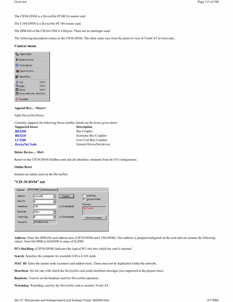
The CIF60-DNM is a DeviceNet PCMCIA master card.
The C104-DNM is a DeviceNet PC104 master card.
The DPRAM of the CIFx0-CNM is 8 Kbytes. There are no interrupts used.
The following description relates to the CIF30-DNM. The other cards vary from the point of view of TwinCAT in form only.
Context menu
Append Box... <Insert>
Adds DeviceNet boxes.
Currently supports the following boxes (further details on the boxes given later):
Delete Device... <Del>
Removes the CIF30-DNM fieldbus card and all subsidiary elements from the I/O configuration.
Online Reset
Initiates an online reset on the DeviceNet.
"CIF-30 DNM" tab
Address: Enter the DPRAM card address here (CIF30-DNM and C104-DNM). This address is jumped/configured on the card and can assume the following values: from 0xC8000 to 0xEE000 in steps of 0x2000
PCI Slot/Ring: (CIF50-DNM) Indicates the logical PCI slot into which the card is inserted.
Search: Searches the computer for available CIFxx-CAN cards
MAC ID: Enter the master node (scanner) card address here. These must not be duplicated within the network.
Heartbeat: Set the rate with which the DeviceNet card sends heartbeat messages (not supported at the present time).
Baudrate: Used to set the baudrate used for DeviceNet operation.
Watchdog: Watchdog, used by the DeviceNet card to monitor TwinCAT.
Supported boxes DescriptionBK5200 Bus CouplerBK5210 Economy Bus CouplersLC5200 Low-Cost Bus CouplersDeviceNet Node General DeviceNet device
Page 113 of 390Overview
8/7/2006file://C:\Documents and Settings\tope\Local Settings\Temp\~hhD469.htm

VendorID: Gives the vendor ID with which the scanner card is identified in the network (e.g. in the Duplicate MAC ID Detection protocol)
AutoClear: If you select this box, a node failure will halt the whole network. Otherwise the system attempts to re-incorporate the node and continues operating.
Synchronous Mode: The highest priority task linked with the corresponding device controls the fieldbus cycle and is thereby synchronised with the fieldbus. All other tasks are served asynchronously via corresponding buffers.
Firmware Update... Update the CIFxx-DNM firmware version here. The currently loaded firmware version is shown in the window - in red if the TwinCAT recognises and is awaiting a more recent version.
Tab ”(Online) DPRAM”
See ”Online Display of DPRAM”
Diagnostic
Global Flags
Error Rem Addr
ErrorEvent (for ErrorRemAddr = 255, Error inside device)
ErrorEvent (for ErrorRemAddr = Station Number, MacId)
Error Code Description Troubleshooting0x00 No error0x01 Ctrl: Parameter error Check Master Parameter
0x02 AClr: Device stops the transmission to all nodes Check cabling, Reconfigure Master
0x04 NExc: at least one node has not reached the data exchange state Check ErrorRemAddr and ErrorEvent. inspect the field device indicated by ErrorRemAddr.
0x08 Fatal error because of heavy buserror Check cabling, inspect the field devices, may one node makes trouble on the bus, Check DeviceNet Voltage
0x10 Event: transmission errors were detected Check cabling, inspect the field devices, may one node makes trouble on the bus, Check Baudrate and MAC Id
0x20 NRdy: HOST is not ready Check TwinCAT System for general errors0x40 Duplicate MacId detected Check Masters MacId0x80 Duplicate MacId Test active Check Baudrate and cabling, Master is may not able to set up his Duplicate Mac Id messages
Error Code Description TroubleshootingStation Number Number of faulted slave device Inspect the field device with the indicated MAC id, Check ErrorEvent Diagnoses
255 Error inside Device Check Master Parameter, Check ErrorEvent Diagnoses
Error Code Description Troubleshooting57 Duplicate MAC Id detected Check the addresses of the field devices, change Masters MAC Id
58 Master Config Error, download error of Master parameter Contact technical support
212 Failure in reading masters data base Contact technical support
Error Code
Description Troubleshooting
30 device access timeout, device stopped communicating Inspect the field device, verify connections, check cabling
32 Device rejects access with unknown error code Check IO features of the device, check explicite access to device, check object class, instance and attribute id
35 Device responses in allocation process with connection error Check IO features of the device, check explicite access to device, check object class, instance and attribute id
36 Produced connection length is different to the configured one Check number of Bytes to be produced by the device, check devices IO configuration
37 Consumed connection length is different to the configured one Check number of Bytes to be consumed by the device, check devices IO configuration
38 Device service response telegram unknown Contact technical support of the device manufacturer
39 Connection already in Request Check cabling, inspect device, Master is not able to set up a connection to the device
Page 114 of 390Overview
8/7/2006file://C:\Documents and Settings\tope\Local Settings\Temp\~hhD469.htm

Beckhoff FC7501/FC7502 The FC7501 respectively FC7502 are single-channel and double-channel SERCOS cards (SERCOS = SEriell Realtime COmmunication System) with PCI interfaces. They can be operated as SERCOS masters and/or as SERCOS slaves. The SERCON816 ASIC is used for this cards. It supports not only 2 and 4 Mbaud, but also 8 and 16 Mbaud. At the moment, neither the transmitter nor the receiver being used are specified for 16 Mbaud, which means that this property can not yet be guaranteed.
Context menu
Append Box... <Insert>
Adds Sercos slaves (boxes). For an Overview of all currently supported SERCOS devices, please see...
Delete Device... <Del>
Removes the FC750x fieldbus card and all subsidiary elements from the I/O configuration.
Online Reset
Initiates an online reset of the Sercos master, so that the phase will switch to phase 0 and will then return to what had previously been the current phase.
"FC7500" tab
40 Number of CAN-message data bytes in read produced or consumed size response not matches expected one Contact technical support of the device manufacturer
41 Predefined Master- / Slave Connection Set already exists Check number of Masters connected to the network, device my already in use by another master
42 Polling IO data length is different to the configured oneCheck number of Bytes to be produced by the field device, check field devices IO configuration, contact technical support of the device manufacturer
43 Sequence Error in fragmented polling IO transmission Inspect device, contact technical support of the device manufacturer44 Fragment Error in fragmented pollingIO transmission Inspect device, contact technical support of the device manufacturer45 Sequence Error in fragmented polling IO transmission Inspect device, contact technical support of the device manufacturer
46 Polling IO data length is different to the configured one Check number of Bytes to be produced by the device, check devices IO configuration, contact technical support of the device manufacturer
47 Sequence Error in fragmented Change of State / Cyclic IO transmission Inspect device, contact technical support of the device manufacturer
48 Sequence Error in fragmented Change of State / Cyclic IO transmission Inspect device, contact technical support of the device manufacturer
49 Sequence Error in fragmented Change of State IO transmission Inspect device, contact technical support of the device manufacturer
50 Change of State / Cyclic IO data length is different to the configured one
Check number of Bytes to be produced by the device, check devices IO configuration, contact technical support of the device manufacturer
TwinCAT System Manager: Reference
Page 115 of 390Overview
8/7/2006file://C:\Documents and Settings\tope\Local Settings\Temp\~hhD469.htm

PCI Slot/Irq: Shows in which logical PCI slot the card was detected and which IRQ is assigned to it. The IRQ is unused.
Search...: Searches for all connected FC750x channels. Select those required. In the case of an FC7502 both channels A and B appear. These behave in logical terms like two FC7501 cards.
PCI-Cfg...: In which the address of the FC750x is set in the lower memory area (below 1 MB) of the PC.
Scan the bus...: The Sercos ring is scanned here, and all devices found are added to the device. The configuration of Beckhoff boxes is read precisely.
Data rate: The Sercos baud rate is set here. 2 Mbaud, 4 Mbaud, 8 Mbaud or 16 Mbaud can be selected.
Transmitter power: The power of the transmitter is set here, depending on the length of optical fibre being used.
Operating mode: The FC750x can be operated as a Sercos master and as a Sercos slave. In either of these operating modes, the card can be operated as the synchronous master (the PC and other synchronous devices receive their clock from the sync master) or as a sync slave (the card, or the card channel, receive the synchronisation signal from the other channel or from another card over the ribbon cable). There can only be one synchronous master within one PC. If both the channels of a FC7502 are used, then only the A-channel (the channel closest to the motherboard) can be used as the sync master.
Start-up to Phase 4: If selected, then every time TwinCAT starts an attempt will be made to bring the Sercos bus into phase 4, and thus to perform cyclical data exchange. If this option is not selected, the card will remain in phase 2. It will then have to be placed into phase 4 at a later stage by ADS from, for example, the PLC.
Check Timing: If selected, then in each cycle the exact real-time behaviour of access to the card is monitored. If not maintained (actual values are read too early, or set values are written too late) then a corresponding counter located in the process data is incremented. This monitoring has only a very small impact on the performance, so that there is no disadvantage to using it in normal applications. In applications with very short cycle times and where performance margins are very tight, however, it can be switched off.
Watchdog: The SERCON816 Sercos ASIC used has a hardware watchdog that monitors regular PC access, activating phase 0 if the accesses cease. The number of cycles that the watchdog will tolerate is given here. The watchdog is deactivated if the figure supplied is 0.
NC Access Time: A figure is given here for the time required by the NC in each cycle for reading the actual values and writing the set values. This value is only used by the internal time slot calculation, so that possible time slot problems can be seen in advance (cf. Check Timing Errors).
NC Shift Time: The NC shift time can be used to delay the time at which the NC begins to read the actual values. The value gives the number of µs after the last AT. The default value of 50µs ensures in normal cases that even if there is a small amount of jitter in the real-time system, the ATs, and therefore the actual values, have safely arrived at the master before the NC takes action. If more than one Sercos ring is in use, it may be necessary to adjust this value, since the NC accesses all the rings at more or less the same time, but the connected devices in particular rings mean that the last ATs arrive at different times. Since the Sercos rings on the bus are synchronised in hardware, the following rule applies: The NC shift time should be set on the various rings in such a way that the resulting tNcAccess time (see timing) is about the same on all the rings. In addition to this, the NC shift time should not be much less than about 20 µs onany ring.
Cycle-Time(3-4): The cycle time of the highest priority associated task is indicated here. This is used in phases 3 and 4.
Cycle-Time(0-2): The cycle time in phases 0 to 2 is given here. This is used for the bus start-up.
The following values make it possible to influence the internal time slot calculation, to make modifications of a few µs in the event of communication problems or loading difficulties. However, this should not be done without the appropriate Sercos expertise, so that the effects can be estimated.
JT1 User: The value set here alters the jitter JT1 used in the internal time slot calculation.
JT2 User: The value set here alters the jitter JT2 used in the internal time slot calculation.
JTSCyc User: The value set here alters the jitter JTSCyc used in the internal time slot calculation.
Page 116 of 390Overview
8/7/2006file://C:\Documents and Settings\tope\Local Settings\Temp\~hhD469.htm

T3 User: The value set here alters the time T3 used in the internal time slot calculation.
T4 User: The value set here alters the time T4 used in the internal time slot calculation.
"Timing (Online/Offline)" tab
The Timing tab provides internal details of the time slot calculation. A distinction is made between and online and an offline mode, since parameters are also read from the devices and included in the calculation of the time slot. In offline mode (TwinCAT is stopped) default values are used for the timing values that are normally read from the devices, so that the result of this calculation can differ slightly from that obtained with the true values. The offline calculation does however as a rule provide a very good estimate of the bus timing. In online mode (TwinCAT is running and the Sercos Bus is in phase 3 or 4) the exact values are displayed, and provide the expert user with very precise information about the timing on the bus.
The diagram in the lower section provides a good summary of the bus loading being generated, and over the capacity still available. A Sercos cycle is displayed between the two red master control telegrams (MST). After the MST the devices first send their drive telegrams (green), and after the NC shift time the NC access time (dotted region) starts, in which the NC accepts the actual values and transmits new set values. The subsequent clear region leading up to the Master Data Telegram (MDT, blue) indicates bus capacity that is still free, and can be used for other devices or for additional data associated with the existing devices.
Not long after the MDT the master sends another MST, so starting the next cycle. Times T3 and T4 indicate when the devices should all simultaneously accept the set values or acquire the actual values.
"Online" tab
The Online tab makes it possible to find the current phase of the Sercos ring and to change it. Three red dashes "---" for the phase indicate a ring that is not closed. A phase indication like "2->3" indicates that a change of phase is currently in progress, and that it is possible that this may take some time.
Tab ”(Online) DPRAM”
See ”Online Display of DPRAM” . The registers in the ASIC can be seen starting at address 0x1000 following the DPRAM of the SERCON816 without a break.
Input Diagnosis
Page 117 of 390Overview
8/7/2006file://C:\Documents and Settings\tope\Local Settings\Temp\~hhD469.htm

The FC750x has a variety of diagnostic variables available automatically. They describe the state of the card and of the Sercos ring:
ActualPhase: The current phase of the Sercos ring is displayed.
RequestedPhase: The phase currently being requested (e.g. by the PLC) is displayed. The card or driver is presently attempting to activate this phase.
SystemState: Gives more precise information about the current phase: 0xE001 = Phase 0 0xE002 = Phase 1 0xE003 = Phase 2 0xE004 = Phase 3 0xE005 = Phase 4 0xE008 = Break 0xE011 = Phase switch 0 -> 1 0xE012 = Phase switch 1 -> 2 0xE013 = Phase switch 2 -> 3 0xE014 = Phase switch 3 -> 4
SystemError: Indicates the current error state: 0x0000 = No error 0x8005 = Drive addresses are incorrect 0x8006 = HS-timeout (service channel) 0x8007 = Double AT-failure 0x8009 = LWL-bus is interrupted 0xD002 = Break 0xD003 = Switch from 2->3 failure (S-0-0127) 0xD004 = Switch from 3->4 failure (S-0-0128) 0xF001 = Configuration error (actual/nominal channel) 0xF002 = Error in the time slot calculation 0xF003 = Incorrect phase setting by the NC 0xF004 = Internal error 0xF005 = Error lifecounter 0xF008 = Double MDT-failure 0xF009 = Double MST-failure 0xF00A = Sync-In signal failure
TimingErrorCnt1: A counter that is incremented if the NC accesses the actual values too early ("Check timing" must have been selected).
TimingErrorCnt2: A counter that is incremented if the NC supplies new set values too late ("Check timing" must have been selected).
RDistErrorCnt: An error counter that counts telegrams received in a damaged state (cf. RDIST in the SERCON816 Reference Manual). The cause can be an incorrect baud rate.
FibBrErrorCnt: An error counter that counts telegrams received in a damaged state (cf. FIBBR in the SERCON816 Reference Manual). The cause can be an incorrect baud rate.
RErrErrorCnt: An error counter that counts telegrams that have been lost or that are received at the wrong time (cf. RERR in the SERCON816 Reference Manual).
MstLateErrorCnt: An error counter that counts MSTs that are received too late (cf. MSTLATE in the SERCON816 Reference Manual).
MstEarlyErrorCnt: An error counter that counts MSTs that are received too early (cf. MSTEARLY in the SERCON816 Reference Manual).
Indramat SERCANS SCS-P The SERCANS SCS-P is a SERCOS master card for up to eight axes. It is supported as both an ISA and a PCI type.
TwinCAT System Manager: Reference
Page 118 of 390Overview
8/7/2006file://C:\Documents and Settings\tope\Local Settings\Temp\~hhD469.htm

The DPRAM of the SERCANS SCS-P is 4 Kbytes. An interrupt is used, which actuates the card and is also used for synchronising functions in the TwinCAT system.
Context menu
Append Box... <Insert>
Delete Device... <Del>
Removes the SERCANS SCS-P fieldbus card and all subsidiary elements from the I/O configuration.
"Sercans SCS-P" tab
Address: ISA: Enter the DPRAM card address here. This address is jumped on the card and can assume the following values: from 0xC0000 to 0xEF000 in steps of 0x1000 PCI: Shows the PCI slot number, the PCI interrupt and the DPRAM address.
Search: Used to search the computer for SERCANS cards of the corresponding type (ISA / PCI).
Cyclic IRQ: Enter the cyclical interrupt used. It must coincide with the card setting (jumper, ISA only). The non-cyclical card interrupt is not required and may not be jumped on the card (ISA only).
Sync Master: See ”Synchronising Several SERCANS Cards”.
Phase 4: Used to specify whether the card should StartUp in phase 4 at the TwinCAT system StartUp. It will otherwise remain in phase 2 and can be switched to phase 4 at a later point via ADS.
Tab ”(Online) DPRAM”
See ”Online Display of DPRAM”
Synchronising Several SERCANS Cards
Supported boxes DescriptionSERCOS Axis Sercos axisBK7500 Bus Coupler
Page 119 of 390Overview
8/7/2006file://C:\Documents and Settings\tope\Local Settings\Temp\~hhD469.htm

If you require more than eight axes, you will need to use 2 or more SERCANS cards. These cards must be synchronised with one another since only one card can control the TwinCAT system. The card which synchronises the TwinCAT system is described a ”Sync Master” and the corresponding check box for this card should be ticked (none of the others). The synchronising process is different depending on whether you are using ISA or PCI cards. You cannot mix ISA and PCI cards in one installation!
Synchronising ISA cards
In the case of the ”slave” cards, you should set the same cyclical interrupt as for the ”master” card. Otherwise, break the J100 connection on the back of the card (including the track)! J100 is to be found on the back, next to the inserted interrupt jumpers. If the card is to be used as a master at a later point, re-solder J100.
Synchronising PCI cards
In the case of PCI cards, synchronisation is carried out via a 10 pin ribbon cable (angled ribbon cable socket on the top), which is used to connect all SERCANS cards in parallel. On the ”master” card you also need to connect a jumper on J108 between PIN 1 PIN 2. This jumper is not required on the ”slave” cards.
Ethernet Miniport (Real-Time) The real-time Ethernet driver allows with TwinCAT Real-Time Ethernet compatible devices a simultaneous usage of the Ethernet network for TwinCAT Real-Time applications and "regular" applications which use the operating system stack (e.g. via TCP/IP).
Real-Time Ethernet compatible devices The real-time Ethernet Miniport driver of TwinCAT works with all Ethernet adapters of the Intel 8255x series and as well with the integrated Ethernet adapter inside the Intel I/O Hub ICH4 (e.g. integrated in i845 chipset). Nevertheless, at least Windows 2000 (or Windows XP) is required as operating system. To use the real-time environment of TwinCAT, the default operating system driver for the network adapter has to be replaced with the one provided by TwinCAT v 2.9. Furthermore, an additional protocol driver "TwinCAT Ethernet Protocol" is required. How to do so, is described in Appendix C.
To verify whether compatible Ethernet adapters are available, the following dialog "TwinCAT Ethernet compatible devices" has been implemented. It can be found inside System Manager under: "Options | Show Real Time Ethernet compatible devices...":
"TwinCAT Ethernet Protocol" installed: This checkbox indicates whether theTwinCAT Protocol driver has been installed already.
Installed and ready to use devices: Shows all adapters which are currently bound to the TwinCAT driver. These adapters should be available in System Manager configurations.
Installed devices but without necessary binding to 'TwinCAT Ethernet Protokoll': Adapters which use the TwinCAT driver but which are not bound to the TwinCAT protocol, are listed in this section. Please see installation instructions in Appendix C.
Compatible devices with incompatible driver installed: Lists all adapters which are TwinCAT Real-Time Ethernet capable if the original driver would be replaced (see: Appendix C).
WARNING: Windows Update or Service Pack installations The advantage that Real-Time Ethernet is based on standard hardware also has a little disadvantage: The operating system identifies the hardware and tries to update the drivers for it with the latest-greatest in certain circumstances. This happens e.g. during "Automatic Updates" as well as during installation of Service Packs. After Service Pack installation, the steps of Appendix C have to be repeated therefore. The automatic Windows update feature can be disabled (please refer to: Control Panel | System | Automatic Updates and disable first checkbox). At manual updates, the recommendation about replacing the "Intel Networking Driver" should be declined. Anyway, after Service Pack installation or update, the current configuration can be checked with upper dialog in any
TwinCAT System Manager: Reference
Page 120 of 390Overview
8/7/2006file://C:\Documents and Settings\tope\Local Settings\Temp\~hhD469.htm

case.
Ethernet Miniport "Adapter" tab After adding an Ethernet Miniport I/O device to the I/O configuration, the following "Adapter" tab is available on the right:
The Ethernet adapter currently selected is shown on this "Adapter" tab.
Search...: Looks for TwinCAT Real-Time Ethernet compatible devices and displays them.
MAC Address: MAC Address of this Ethernet controller (at configured network adapters)
IP Address: Settings taken from Windows Registry. These can be changed under "Control Panel | Network Connections" in the TCP/IP 'Properties..' section.. If Real-Time Ethernet and "normal" Ethernet are both used on the same system with two different network adapters, the subnet addresses of these adpaters (NICs) must differ! Nevertheless, the Real-Time Ethernet belonging devices have to be configured with the same subnet address (first two quadruples) as the Ethernet Miniport adapter and vice-versa, of course.
Freerun Cycle: The cycle time used if Free-Run is active (Config Mode only), can be set here. The cycle time in Run mode results automatically in reference to the task with the highest priority linked to the variables of the adapter or one of its nodes.
Lock I/O after Link Error: If this box is checked, the process data exchange doesn't resume automatically after a resolved link problem (e.g. when the network cable has been unplugged). In such a situation, an I/O Reset is necessary afterwards, instead.
Supported devices / protocols For a list of supported devices, see Overview. Since TwinCAT Real-Time Ethernet supports all Ethernet protocols by principle - means standard protocols as well as special Real-Time communication protocols - this list of supported devices is just a snapshot and will be certainly extended in the future.
Status inputs and Control outputs Underneath a configured RT Ethernet device, a status variable and a control variable shows up and can be linked to other tasks (e.g. TwinCAT PLC tasks).
Inputs:
Variable DescriptionDevState Device status information as WORD (or UINT) variable, assumes the following values:
0x0001 = Link error 0x0002 = I/O locked after link error (I/O reset required) 0x0010 = Out of send resources (I/O reset required) 0x0020 = Watchdog triggered 0x0040 = TwinCAT Real-Time Ethernet driver not found 0x0080 = I/O reset active
Page 121 of 390Overview
8/7/2006file://C:\Documents and Settings\tope\Local Settings\Temp\~hhD469.htm

Outputs:
Virtual Ethernet Interface The virtual Ethernet interface adds network interface cards (NIC), which are configured on a Windows NT / 2000 / XP Operating System or on a Beckhoff CX100x, to the TwinCAT I/O configuration. Via this network adaptor-independent virtual Ethernet Interface, Beckhoff Ethernet devices can be added to the TwinCAT I/O configuration, now.
Context Menü
Append Box <Ins>
Adds a Beckhoff Ethernet fieldbus device (Box) to the configuration. For an Overview of all currently supported Beckhoff Ethernet devices, please see...
Delete Device <Del>
Removes the virtual Ethernet Interface and all sub entries from the I/O configuration
Online Reset
Initiates an Online Reset on all Beckhoff Ethernet devices which are connected to this network.
"ADS" Tab
See -> "ADS Settings at I/O Devices"
EtherCAT(Direct Mode) device The EtherCAT(Direct Mode) is a Real Time Ethernet Device that only supports the EtherCAT protocol. Internally it uses the same network drivers as the standard Real-Time Ethernet device(see Ethernet Miniport (Real-Time)) . Install instructions for the network drivers can be viewed under Appendix C. The EtherCAT (Direct Mode) device should be used, if only EtherCAT slave devices are connected to the network adapter. It offers additional features not available in the standard Real-time Ethernet device. If you scan for the device, at least one EtherCAT slave device should be connected to the device,
Variable DescriptionDevCtrl Device control variable of type WORD (or UINT).
Has currently no impact on the network adapter!
TwinCAT System Manager: Reference
TwinCAT System Manager: EtherCAT
Page 122 of 390Overview
8/7/2006file://C:\Documents and Settings\tope\Local Settings\Temp\~hhD469.htm

otherwise the Rt-Ethernet device is selected. To change the device type from Real-Time Ethernet device to EtherCAT(Direct Mode), you have to open the context menu of the device in the System Manager tree view. Then you have to select the menu entry "Change To/ EtherCAT(Direct Mode)":
EtherCAT(Direct Mode) "Adapter" tab After adding an EtherCAT(Direct Mode) to the I/O configuration, the following "Adapter" tab is available on the right:
The Ethernet adapter currently selected is shown on this "Adapter" tab.
Search...: Looks for TwinCAT Real-Time Ethernet compatible devices and displays them.
MAC Address: MAC Address of this Ethernet controller
IP Address: Settings taken from Windows Registry. These can be changed under "Control Panel | Network Connections" in the TCP/IP 'Properties..' section.. If Real-Time Ethernet and "normal" Ethernet are both used on the same system with two different network adapters, the subnet addresses of these adapters (NICs) must differ! Nevertheless, the Real-Time Ethernet belonging devices have to be configured with the same subnet address (first two quadruples) as the Ethernet Miniport adapter and vice-versa, of course.
Page 123 of 390Overview
8/7/2006file://C:\Documents and Settings\tope\Local Settings\Temp\~hhD469.htm

Freerun Cycle: The cycle time used if Free-Run is active (Config Mode only), can be set here. The cycle time in Run mode results automatically in reference to the task with the highest priority linked to the variables of the adapter or one of its nodes.
Lock I/O after Link Error: If this box is checked, the process data exchange doesn't resume automatically after a resolved link problem (e.g. when the network cable has been unplugged). In such a situation, an I/O Reset is necessary afterwards, instead.
Promiscuous Mode(use with Netmon/Ethereal only): This check box should only be enabled, if one wants to capture the network traffic with tools like Ethereal or the Microsoft Network monitor. If this box is checked, the Real-Time Ethernet miniport device copies all frames to the NDIS protocol layer of windows. This allows protocol drivers to capture the frames.
EtherCAT(Direct Mode) "EtherCAT" tab:
NetId: This is the NetId of the EtherCAT master device. The NetId is a parameter necessary for communicating with the EtherCAT master device via ADS. The ADS port of the EtherCAT master is always 0xFFFF(65535) and the Ads Port of an EtherCAT slave device is equal to the fixed address (see EtherCAT Addr) of the slave.
Advanced Settings...: Opens the Advanced Settings Dialog. This dialog contains additional settings for the EtherCAT master device.
Export Configuration File...: Creates the XML Master Configuration file . This file describes the process data and the frames sent during the EtherCAT state transitions.
Sync Unit Assignment...: Opens the "Sync Unit Assignment" dialog. This dialog can be used to group EtherCAT slave devices into separate sync units.
Topology...: Opens the "Topology" dialog. This dialog displays the topology of the configured EtherCAT slave devices.
The list view at the bottom displays all cyclic EtherCAT commands sent by the EtherCAT master:
EtherCAT(Direct Mode) "Online" tab:
Column DescriptionFrame The cyclic frame the EtherCAT command is contained in. One EtherCAT frame can contain one or more EtherCAT commands.Cmd The type of the command.
Addr
Address of the data section of the EtherCAT slave devices this command addresses. If the EtherCAT command uses logical addressing (LRW, LW or LR) "Addr" specifies the logical address. Otherwise the upper 16 Bit always specifies the physical memory address and the lower 16 Bits either the fixes address of the device (see EtherCAT Addr) or the auto increment address of the device (see Auto Inc Addr) dependent on the type of the command.
Len Length of the data section.
WCExpected working counter. Each EtherCAT slave that is addressed by an EtherCAT command increments the working counter. If it is a Logical Read Write(LRW) command each EtherCAT slave device data is written to increases the working counter by 2 and each EtherCAT slave data is read from increases the working counter by 1.
Sync Unit Sync Unit the EtherCAT command belongs to.Cycle Time(ms) Cycle time with which the frame is sent.
Page 124 of 390Overview
8/7/2006file://C:\Documents and Settings\tope\Local Settings\Temp\~hhD469.htm

Actual State: Shows the current state of the EtherCAT master device.
Send Frames: Shows the number of frames sent by the EtherCAT master device.
Frames: Shows the number of sent frames per second.
Init: Requests the 'Init' state from the master.
Pre-Op: Requests the 'Pre-Op' state from the master.
Safe-Op: Requests the 'Safe-Op' state from the master.
Op: Requests the 'Op' state from the master.
Clear CRC: Clears the CRC counters of the EtherCAT slave devices.
ClearFrames: Resets the counter displayed in the "Send Frames" edit box to 0.
The list view shows all the EtherCAT slave devices and their corresponding states and CRC counters:
To request a specific state from an individual EtherCAT slave device one has to right click on the slave device in the list view. This opens following context menu:
Now one can select one of the "Request 'xxx' state" menu items to set the device into a different state.
Column DescriptionNo Physical position of the device in the communication ringAddr Fixed address (see EtherCAT Addr) of the slave device. Name Name of the EtherCAT device
State State of the EtherCAT slave device. The state can be either INIT, PRE-OP, SAFE-OP or OP. If the device cannot be found by the master or the slave is unable to change the state, ERR + the last known valid state is displayed.
CRC CRC counter of the EtherCAT slave device. If an individual slave device is selected in the list, the CRC counters of the ports A,B and C(if in use) are listed in brackets.
Page 125 of 390Overview
8/7/2006file://C:\Documents and Settings\tope\Local Settings\Temp\~hhD469.htm

EtherCAT Diagnostic Inputs
FrmXState: Variable of type WORD (or UINT), that shows the state of the frame X. For each EtherCAT command in the frame, a bit is reserved in FrmXState:
FrmXWcState: Variable of type WORD(or UINT), that shows the working counter states of the individual EtherCAT commands of the cyclic frame X. For each EtherCAT command in the frame, a bit is reserved in FrmXWcState:
An EtherCAT frame can consist of one or more EtherCAT commands. Each of these commands has an expected working counter value. In other words the master knows, how many slave devices are addressed by an individual command and can calculate the expected working counter. If the master receives a wrong working counter this indicates, that one or more slaves have a problem. In this case the corresponding bit in FrmXWcState is set.
In the Example above only one frame (Frame0) is sent cyclically during process data communication. In the "EtherCAT" tab of the EtherCAT device one can see the individual cyclic frames and the EtherCAT commands contained in them :
TwinCAT System Manager: EtherCAT
Bit Description0 (0x0001) 1. EtherCAT command not sent (NOP requested)1 (0x0002) 2. EtherCAT command not sent (NOP requested)2 (0x0004) 3. EtherCAT command not sent (NOP requested)... 14 (0x4000) 15. EtherCAT command not sent (NOP requested)15 (0x8000) complete frame not sent
Bit Description0 (0x0001) wrong working counter of 1. EtherCAT command received1 (0x0002) wrong working counter of 2. EtherCAT command received2 (0x0004) wrong working counter of 3. EtherCAT command received... 14 (0x4000) wrong working counter of 15. EtherCAT command received15 (0x8000) complete frame missing
Page 126 of 390Overview
8/7/2006file://C:\Documents and Settings\tope\Local Settings\Temp\~hhD469.htm

The first command is a Logical Read Write command and the second is a broadcast read command. The LRW command is responsible for reading the inputs and writing to the outputs of one or more slave devices. The BRD(Broad Cast Read) command reads out the combined states of all slaves.
Slave Count: Number of slave devices connected to the EtherCAT master.
DevState: Device status information as WORD (or UINT) variable, assumes the following values:
The bits 8-11 of the device state variable indicate if one or more Slave devices are in a specific state. During process data communication the slaves are in the state Operational. In this case bits 8-11 are set to 0. If one slave device is in the Init state instead of Operational, the bit 8 would be set (DevState = 0x0100).
EtherCAT Slave Device
Additionally to diagnostics inputs of the EtherCAT device, each slave device as a optional diagnostic input variable called WcState:
WcState: Variable of type BOOL, that shows the working counter state of the EtherCAT slave device. A value of 0 indicates a valid working counter and a value of 1 an invalid working counter. If the working counter is invalid, this indicates that the EtherCAT command, that is responsible for updating the inputs and outputs for this device, has an incorrect working counter. Because this command can address more than 1 slave device, the variable WcState of all involved devices will be set to invalid and one cannot determine the device that causes the problem with the help of this variable. To determine if an individual slave device has a problem, one can read out the state of the device with the help of the InfoData.State variable.
Info Data
If 'Info Data' is enabled (see Master Settings), the 'Info' device image is added to the EtherCAT device. Additionally an entry 'InfoData' is added to the EtherCAT device and to the connected EtherCAT slave devices. 'InfoData' contains input variables, that supply information about the EtherCAT device, that normally do not change very often. Variables mapped to the 'Info' images are not updated cyclically but only if the image has changed.
ChangeCnt: The ChangeCnt shows how often the contents of the image has changed.
DevId(optional): This is the device id of the EtherCAT device.
Bit Description:0 (0x0001) Link error detected. 1 (0x0002) I/O locked after link error (I/O reset required)2 (0x0004) Link error (redundancy adapter)3 (0x0008) Missing one frame (redundancy mode)4 (0x0010) Out of send resources (I/O reset required)5 (0x0020) Watchdog triggered6 (0x0040) Ethernet driver (miniport) not found7 (0x0080) I/O reset active8 (0x0100) At least one device in 'INIT' state9 (0x0200) At least one device in 'PRE-OP' state10 (0x0400) At least one device in 'SAFE-OP' state11 (0x0800) At least one device indicates an error state12 (0x1000) DC not in sync
Page 127 of 390Overview
8/7/2006file://C:\Documents and Settings\tope\Local Settings\Temp\~hhD469.htm

AmsNetId(optional): The AmsNetId is a parameter necessary for communicating with the EtherCAT master device via ADS. The ADS port of the EtherCAT master is always 0xFFFF(65535) and the Ads Port of an EtherCAT slave device is equal to the fixed address (see EtherCAT Addr) of the slave.
EtherCAT Slave Device
State: The 'State' variable holds the current EtherCAT state and link status of the EtherCAT slave device.
AdsAddr( optional ): The variable 'AdsAddr' holds the Ams netId and Ams port of the slave device. These are necessary parameters for communicating with the EtherCAT slave device via ADS. The variable 'AdsAddr' is added by default, if the slave supports a mailbox.
Chn0( optional for drives only): Drive channel.
Additional Diagnostic information Additional non cyclic diagnostic information can be found on the Online tab of the EtherCAT device.
ADS Interface Acyclic data can be transmitted to or from the EtherCAT device via ADS-Read or ADS-Write commands. It possible to communicate with the mailboxes of EtherCAT slave devices via ADS. Every EtherCAT device has its own Net-ID. The port depends on the individual Ads service :
Value Description0x___1 Slave in 'INIT' state0x___2 Slave in 'PREOP' state0x___3 Slave in 'BOOT' state0x___4 Slave in 'SAFEOP' state0x___8 Slave in 'OP' state0x0010 Slave signals error0x0020 Invalid vendorId, productCode... read0x0100 Slave not present0x0200 Slave signals link error0x0400 Slave signals missing link
0x0800 Slave signals unexpected link
0x1000 Communication port A
0x2000 Communication port B
0x4000 Communication port C0x8000 Communication port D
TwinCAT System Manager: EtherCAT
Port Description65535 (0xFFFF) General Ads services handled by the master directly. 0x1 - 0xFFFE (fixed address of a slave device) This is an Ads services directed at an individual slave device. The port number is the same as the
EtherCAT address of the slave device.
Page 128 of 390Overview
8/7/2006file://C:\Documents and Settings\tope\Local Settings\Temp\~hhD469.htm

The NetId can be found in the edit field "NetId" on the EtherCAT tab of the EtherCAT master device:
The NetId can also be read out from the variable InfoData.AmsNetId:
Master Ads Port (0xFFFF)
The following table lists the Ads commands supported by the EtherCAT master port(0xFFFF):
Index Group Index Offset Access Data type Phys. unit
Def. range
Description Remarks
0x00000003 0x00000100 R UINT16 Returns current state of master. Following values are returned by this service:
0x0000: Init State 0x0002: Pre-Operational State 0x0003: Bootstrap State 0x0004: Safe-Operational State 0x0008: Operational State
Page 129 of 390Overview
8/7/2006file://C:\Documents and Settings\tope\Local Settings\Temp\~hhD469.htm

0x00000003 requested state W Request State from master.
0x00000006 0x00000000 R UINT16 Returns the number of projected slaves.
0x00000007 0x00000000 R UINT16[nSlaves] Returns the fixed addresses of all slaves.
0x00000009 0x00000000 R
{ Returns the EtherCAT status and the Link status of all Slaves:
BYTE
EtherCAT state of a slave. The state can adopt one of the following values:
0x0000: Init State 0x0002: Pre-Operational State 0x0003: Bootstrap State 0x0004: Safe-Operational State 0x0008: Operational State
In the case of an error state, the error bit is also set: 0x0010: Error State
BYTE
Link status of an EtherCAT slave. The Link status can consist of an ORing of the following bits:
0x0000: Link ok. 0x0001: Link not present 0x0002: No communication 0x0004: Link missing 0x0008: Additional link 0x0010: Port A 0x0020: Port B 0x0040: Port C 0x0080: Port D
exampe: 0x0024 = Missing Link at port B. }[nSlaves]
0x00000009
0x00000001-0x0000FFFF
(EtherCAT slave address)
R
{ Returns the EtherCAT status of the EtherCAT slave specified in the index offset.
BYTE
EtherCAT state of the slave. The state can adopt one of the following values:
0x0000: Init State 0x0002: Pre-Operational State 0x0003: Bootstrap State 0x0004: Safe-Operational State 0x0008: Operational State
In the case of an error state, the error bit is also set: 0x0010: Error State
BYTE
Link status of an EtherCAT slave. The Link status can consist of an ORing of the following bits:
0x0000: Link ok. 0x0001: Link not present 0x0002: No communication 0x0004: Link missing 0x0008: Additional link 0x0010: Port A 0x0020: Port B 0x0040: Port C 0x0080: Port D
exampe: 0x0024 = Missing Link at port B. }
0x00000009 0x00000001-
0x0000FFFF
W UINT16 Request a new state from the selected EtherCAT slave.
Page 130 of 390Overview
8/7/2006file://C:\Documents and Settings\tope\Local Settings\Temp\~hhD469.htm

Slave Ads Port(0x1 - 0xFFFE) The following table lists the Ads commands that can be sent to an EtherCAT slave device. The port number is same as the fixed address of the slave device:
(EtherCAT slave address)
0x00000011
0x00000001-
0x0000FFFF
(EtherCAT slave address)
R
{ Returns the CANopen identity object of an EtherCAT slave device.
UINT32 Vendor IdUINT32 Product CodeUINT32 Revision NumberUINT32 Serial Number}
0x00000012 0x00000000 R
{ Returns the Crc error counters of all slaves.
UINT32 Crc error counter of port A.UINT32 Crc error counter of port A.UINT32 Crc error counter of port A.}[nSlaves]
0x00000012
0x00000001-
0x0000FFFF
(EtherCAT slave address)
R
{ Returns the Crc error counters of the EtherCAT slave specified in the index offset.
UINT32 Crc error counter of port A.UINT32 Crc error counter of port A.UINT32 Crc error counter of port A.
}
Index Group Index Offset Access Data type Phys. unit
Def. range
Description Remarks
CANopen over EtherCAT
0x0000F302 Index and Subindex of an SDO.
HIWORD(0xyyyy0000)= index
LOBYTE(0x000000yy)= subindex
Example:
0x1c120001:
index = 0x1c12 subindex = 1
R/W UINT8[n] SDO Upload/Download Request. The object is selected with the index offset.
0x0000F3FC List type = HIWORD(0xyyyy0000)
Example
0x00000000: return length of the indiviual list types
0x00010000:
R { Returns the indexes of the list type specified in the index offset. If 0 is passed as index offset the length of each list type is returned.
UINT16 list type = 0 :number of list types
list type > 0 :list type
UINT16[n]
list type = 0: length of the list type n+1
list type > 0: length of the selected list
Page 131 of 390Overview
8/7/2006file://C:\Documents and Settings\tope\Local Settings\Temp\~hhD469.htm

Sync Units A Sync Unit describes a module, that defines a set of process data, that should be exchanged synchronously and consistently between the master and one or more EtherCAT slave devices. For each Sync Unit a separate EtherCAT command is sent synchronous with the cycle, to exchange the process data with the EtherCAT slave devices. Every Sync Unit has a diagnostic input, that is synchronous with the cycle and shows, if the complete data is valid (see WcState). Sync Units are useful in applications, where parts of the machine should keep on operating, although others parts have dropped out or have been deactivated.
Sync Unit Assignment
return indexes of all objects
}
0x0000F3FD index = HIWORD(0xyyyy0000)
R Get SDO info description
0x0000F3FE
index = HIWORD(0xyyyy0000)
subindex = LOBYTE of LOWORD (0x000000yy)
valueInfo = HIBYTE of LOWORD (0x0000yy00)
R Get SDO info entry description
Servo Drive over EtherCAT
0x0000F420 IDN = LOWORD(0x0000yyyy)
element = LOBYTE of HIWORD (0x00yy0000):
Drive Number = Bits 1-3 of HIBYTE of HIWORD (0xy0000000)
Command Flag = Bit 8 of HIBYTE of HIWORD (0xy0000000)
0x01 Data Status
0x02Name (read only)
0x04 Attribute0x08 Unit0x10 Minimum0x20 Maximum0x40 Value0x80 Default
R/W UINT8[n] Upload/Download IDN
TwinCAT System Manager: EtherCAT
Page 132 of 390Overview
8/7/2006file://C:\Documents and Settings\tope\Local Settings\Temp\~hhD469.htm

For each EtherCAT slave device, one can define one or more process data areas, that should be exchanged synchronously and consistently. These individual process data areas can be configured in the Process Data tab of a slave device. Normally every PDO object is assigned to the same process data area(Sync Unit). This is indicated by the column SU(Sync Unit) in the PDO List View:
In the example above all channels are assigned to the Sync unit 0. The number of independent process data areas of an EtherCAT slave device, depends on the implementation and resources of its EtherCAT slave controller(Sync Manager and Fmmu). The Sync Units of the EtherCAT slave devices can be assigned to Sync Units of a specific Sync Task. These Sync Units are marked with freely definable names. One can either assign each Sync Unit of a slave individually to a Sync Unit, by pressing the "Sync Unit Assignment..." on the "Process data" tab of a slave(see dialog above), or one can assign one or more slave Sync Units by pressing the "Sync Unit Assignment..." button on the "EtherCAT" tab of the EtherCAT master device:
Sync Unit Assignment dialog
To assign a Sync Unit to a process data area of an EtherCAT slave device, select an entry in the list view above. Then type the name of the Sync Unit in the edit field below or select one of the entries in the list box below. In the example above 'sync unit 1' of Task 1 is assigned to Sync Unit 0 of Term 1 and 'sync unit 2' of Task 1 is assigned to Sync Unit 0 of Term 3.
The 'EtherCAT' tab of the EtherCAT slave devices displays the cyclic frames sent by the EtherCAT master for the process data communication:
Page 133 of 390Overview
8/7/2006file://C:\Documents and Settings\tope\Local Settings\Temp\~hhD469.htm

For each sync task taking part in process data communication a separate frame is sent. The maximal number of sync tasks is set to 4 by default. To change the maximal number of sync tasks, one has to open the Advanced Settings Dialog and select the Sync Tasks page. It is possible to assign one or more Sync Units for a specific task. Each of these Sync Units is assigned to a process data area of a slave device. For each Sync Unit of a sync task the EtherCAT frame contains a separate EtherCAT command. In the example above the first EtherCAT command of the first EtherCAT frame exchanges the process data of the EtherCAT devices assigned to the Sync Unit 1 of Task 1. In this case it is only the one EtherCAT slave device Term1(EL9800)(see Sync Unit Assignment dialog above). For each Sync Unit of a task an expected working counter is calculated, that is displayed in the column 'WC'.
Working Counter: The working counter of an EtherCAT command is a 16 bit counter. The counter is incremented by each EtherCAT slave, that is successfully addressed by the command. If only inputs are read from the EtherCAT slave device, the working counter is incremented by 1. If outputs are written to the EtherCAT slave device, the working counter is incremented by 2. If both inputs and outputs variables are exchanged the working counter is incremented by 3. If the working counter is incorrect the EhterCAT master discards the received inputs of the EtherCAT command.
For each frame the master has an diagnostic input 'FrmXWcState' (X =frame number), that shows the working counter states of the individual EtherCAT commands of the frame (see FrmXWcState). With 'FrmXWcState' it is not possible to verify which Term is responsible for the incorrect working counter . To retrieve more detailed information about the states of the individual slave devices, one has to read out the input variable InfoData.State of the slaves.
Example: 1. Open a new System Manager Project
2. Add a EtherCAT device to the I/O devices in the tree view of the system manager
3. Append an EK1100 and three EL1004 to the EtherCAT device.
4. Expand the entry 'System-Configuration' in the tree view of the system manager
5. Open the context menu of 'Additional Task' by right clicking on the subitem 'Additional Task' of 'System-Configuration'
6. Select the menu entry 'Append Task...' to add Task1
7. In the tab 'Task' of the additional task 'Task1' check the Auto-Start box and change the cycle time to 1 ms.
Page 134 of 390Overview
8/7/2006file://C:\Documents and Settings\tope\Local Settings\Temp\~hhD469.htm

8. Repeat step 5 to 7 to add another task and set the cycle time to 5ms. The current configuration should look like this:
9. Next we will add input variables to the Task 2 and map these to the inputs of the terms. Right click on the entry 'Inputs' of Task 2 and select 'Insert Variable...' in the context menu. In the 'Insert Variable' dialog select 'Bit' as variable type and press the 'OK' button.
10. Double click on the newly created variable and map this variable to first input of Term 2. Add another two variables to Task 2 and map these to the first input of Term 3 and the first input of Term 4 :
Page 135 of 390Overview
8/7/2006file://C:\Documents and Settings\tope\Local Settings\Temp\~hhD469.htm

11. Select the EtherCAT device in the tree view of the system manager and open the 'EtherCAT' tab on the right:
In the list view of this page we can see that one frame containing two EtherCAT commands is sent by the master. The first command is a LRW(Logical Read Write) command and is responsible for reading the inputs and writing to the outputs of one or more slave devices. The column 'Sync Unit' specifies the Sync Unit this command is assigned to. Because we have not yet assigned any Sync Units, the default Sync Unit is used. Because all variables are mapped to
Page 136 of 390Overview
8/7/2006file://C:\Documents and Settings\tope\Local Settings\Temp\~hhD469.htm

Task2, the value 'Cycle (ms)' is set to 5ms, the cycle time of Task2. The expected working counter(WC) is set to 3, one for each slave device. This is the case because the connected slaves devices have only input variables.
12. Next we will add two Sync Units and will assign one to the process data of the first EL1004(Term 2) and the others to Term 3 and Term4 . Press the button 'Sync Unit Assignment...' on the EtherCAT page to open the 'Sync Unit Assignment' dialog :
Select the first entry and type 'sync unit 1' into the edit field below. Now we have created a new Sync Unit called 'sync unit 1' and have assigned it to the Sync Unit 0 of Term2(EL2004). Then select the Term 3 and type 'sync unit 2' into the edit field and finally select term 4 and type 'sync unit 2' into the edit field again. Press the 'OK' button to close the dialog:
As a consequence of the Sync Unit assignment another EtherCAT command has been added to the list of cyclic commands. The first 'LRW' command is responsible for the process data communication of all EtherCAT slave devices belonging to the Sync Unit 'sync unit 1'. In our case this is only the Term 2. The second 'LRW' command is responsible for the process data communication of all EtherCAT slave devices belonging to the Sync Unit 'sync unit 2' (here Term 3 and Term 4). Now it is possible to monitor the working counter state of the first command and second command separately with help of the 'Frm0WcState' input variable:
Page 137 of 390Overview
8/7/2006file://C:\Documents and Settings\tope\Local Settings\Temp\~hhD469.htm

If Term 2 returns an incorrect working counter bit 1 of the variable 'Frm0WcState' would be set to 1, indicating that a wrong working counter has been received for the first EtherCAT command. As a consequence the received data will be discarded and will not be copied to the input variable. If the second EtherCAT command has a correct working counter the received data for Term 3 and Term 4 will be processed normally. If the second EtherCAT command returns an incorrect working counter, bit 2 of 'Frm0WcState' is set. This indicates that either Term 3 or Term 3 or even both Term 2 and Term 3 have not incremented the working counter correctly. Therefore it is not possible to verify with 'Frm0WcState', which Term is responsible for the incorrect working counter . To retrieve more detailed information about the states of the individual slave devices one has to read out the variable InfoData.State.
13. Finally we will add a input variable to Task 1and map this variable to Channel 2 of Term 4:
14.Select the EtherCAT device in the tree view of the system manager and open the 'EtherCAT' tab on the right:
Page 138 of 390Overview
8/7/2006file://C:\Documents and Settings\tope\Local Settings\Temp\~hhD469.htm

Here we can see that another frame has been added to the list. The first frame consists of only one LRW EtherCAT command with the cycle time of 1 ms, corresponding to the cycle time of Task 1 . This command is sent cyclically by the Task 1 and is responsible for reading the inputs of Term 4. Although the first input of Term 4 is mapped to the Task 2 the input is also read out by the EtherCAT command belonging to the Task 1. This is the case because Term 4 only has one process data area. In this case the task with the highest priority is selected for the process data communication with the slave device. The second frame is sent cyclically by the Task 2 with a cycle time of 5ms. The BRD command is always sent by the task with the lowest priority. The individual Sync Units can be viewed by pressing the 'Sync Unit Assignment ...' button:
Here we can see that the Sync Unit 0 of Term 4 is assigned to 'sync unit 2' of Task 2. Because we now have two frames, the input variables 'Frm1State' and 'Frm1WcState' have been added to the device. With the help of these inputs the state and the working counter state of the second frame can be read out.
Page 139 of 390Overview
8/7/2006file://C:\Documents and Settings\tope\Local Settings\Temp\~hhD469.htm

EtherCAT Advanced Settings Dialog After adding an EtherCAT(Direct Mode) to the I/O configuration, open the "EtherCAT" tab on the right and press the "Advanced Settings..." button. This opens the "Advance Settings" dialog. Following dialogs are included in the 'Advanced Settings' dialog:
State Machine Master Settings:
Startup State: The EtherCAT master runs to checked state after startup . If for instance 'OP' is checked the EtherCAT master runs through all EtherCAT states to arrive at 'OP' state. To stay in the state 'INIT' after startup one would have to check the 'INIT' button.
Run Time Behaviour
Log Topology Changes: If this box is checked, topology changes are logged.
TwinCAT System Manager: EtherCAT
Dialog DescriptionStateMachine Master
SettingsGeneral settings of the master.
Slave Settings With the help of the 'Slave Settings' dialog the user can change settings for all EtherCAT slaves. To change these settings for an individual EtherCAT slave device, open the 'Advanced settings' dialog of the slave and open the 'Behaviour' dialog.
Cyclic Frames Sync Tasks With the help of 'Sync Tasks' dialog one can set the maximal number of sync tasks and the MTU of the cyclic Ethernet Frames
sent by the master.Distributed Clocks Master The 'Distributed Clocks Master' dialog enables the user to view and change the master settings of the distributed clocks.
Diagnosis Online View The 'Online View' dialog enables the user to add additional columns to the list view of the 'Online' tab of the EtherCAT device.
Page 140 of 390Overview
8/7/2006file://C:\Documents and Settings\tope\Local Settings\Temp\~hhD469.htm

Log CRC Counters: If this box is checked, the CRC counters are logged.
ReInit after Communication Error: If this box is checked, all slaves are set to init after a communication error has occurred.
Info Data
Enable: If this box is checked, the 'Info' device image is added to the EtherCAT device:
Additionally an entry 'InfoData' is added to the EtherCAT device and to the connected EtherCAT slave devices. 'InfoData' contains input variables that supply information about the EtherCAT device, that normally do not change very often. Variables mapped to the 'Info' images are not updated cyclically, but only if the image has changed. The ChangeCnt shows how often the contents of the image has changed.
Include Device Id: If this box is checked, the input variable 'DevId' is added to InfoData. This is the device id of the EtherCAT device.
Include Ads NetId: If this box is checked, the input variable 'AmsNetId' is added to InfoData. The AmsNetId is a parameter necessary for communicating with the EtherCAT master device via ADS. The ADS port of the EtherCAT master is always 0xFFFF(65535) and the Ads Port of an EtherCAT slave device is equal to the fixed address (see EtherCAT Addr) of the slave.
State Machine Slave Settings: With the help of the 'Slave Settings' dialog the user can change settings for all EtherCAT slaves. To change these settings for an individual EtherCAT slave device, open the 'Advanced settings' dialog of the slave and open the 'Behaviour' dialog.
Startup Checking
The user can specify which slave information should be checked by the master during startup.
Check Vendor Ids: If this box is checked, the master checks if the vendor id of each slave device is the same as the configured one.
Page 141 of 390Overview
8/7/2006file://C:\Documents and Settings\tope\Local Settings\Temp\~hhD469.htm

Check Product Codes: If this box is checked, the master checks if the product code of each slave device is the same as the configured one.
Check Revision Numbers: If this box is checked, the master checks if the revision number of each slave device is the same as the configured one.
Check Serial Numbers: If this box is checked, the master checks if the serial number of each slave device is the same as the configured one.
State Machine
Auto Restore States: If this box is checked, the EtherCAT master tries to restore the state of an EtherCAT slave automatically. If an EtherCAT slave device changes from error state (ERR SAFE-OP, ERR OP etc.) to a valid state(SAFE-OP, OP etc), the EtherCAT master tries to set the device to the current state of the master.
ReInit after Comm. Error:
Info Data
To enable this group, the Info Data has to be enabled in the 'Master Settings' dialog.
Include State: If this box is ckecked, the input variable 'State' is added to the InfoData entry of each EtherCAT slave. This variable holds the current EtherCAT state and link status of an EtherCAT slave.
Include Ads Address: If this box is checked, the input variable 'AdsAddress' is added to the InfoData entry Info of each EtherCAT slave. This variable is added by default for all EtherCAT slaves, that support a mailbox protocol like CoE(CANopen over EtherCAT) or SoE.
Include Drive Channels: If this box is checked, the input variables 'ChnX'(X=Channel number) are added to the InfoData entry of every drive.
Synchronization Sync Tasks: With the help of 'Sync Tasks' dialog one can set the maximal number of sync tasks and the MTU of the cyclic Ethernet Frames sent by the master.
Max Sync Tasks: Maximal number of tasks that can take part in process data communication. How many tasks really take part in the process data communication, depends on the mapping of the variables of the EtherCAT slave devices. For each task that takes part in process data communication at least one EtherCAT frame is sent cyclically. If "Max Sync Tasks" is set to two and the configuration consists of two EtherCAT slave devices whose variables are mapped to two different tasks, two tasks would take part in the process data communication. If the variables were mapped to the same task, only one task would take part in the process data communication.
MTU: The MTU(Maximum Transmission Unit) specifies the maximum size in bytes of the cyclic Ethernet Frames sent by the master. The minimum size is
Page 142 of 390Overview
8/7/2006file://C:\Documents and Settings\tope\Local Settings\Temp\~hhD469.htm
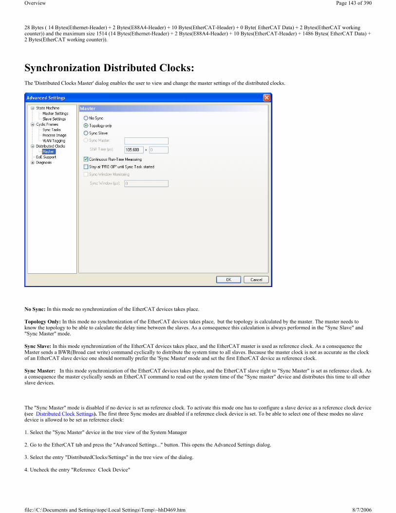
28 Bytes ( 14 Bytes(Ethernet-Header) + 2 Bytes(E88A4-Header) + 10 Bytes(EtherCAT-Header) + 0 Byte( EtherCAT Data) + 2 Bytes(EtherCAT working counter)) and the maximum size 1514 (14 Bytes(Ethernet-Header) + 2 Bytes(E88A4-Header) + 10 Bytes(EtherCAT-Header) + 1486 Bytes( EtherCAT Data) + 2 Bytes(EtherCAT working counter)).
Synchronization Distributed Clocks: The 'Distributed Clocks Master' dialog enables the user to view and change the master settings of the distributed clocks.
No Sync: In this mode no synchronization of the EtherCAT devices takes place.
Topology Only: In this mode no synchronization of the EtherCAT devices takes place, but the topology is calculated by the master. The master needs to know the topology to be able to calculate the delay time between the slaves. As a consequence this calculation is always performed in the "Sync Slave" and "Sync Master" mode.
Sync Slave: In this mode synchronization of the EtherCAT devices takes place, and the EtherCAT master is used as reference clock. As a consequence the Master sends a BWR(Broad cast write) command cyclically to distribute the system time to all slaves. Because the master clock is not as accurate as the clock of an EtherCAT slave device one should normally prefer the 'Sync Master' mode and set the first EtherCAT device as reference clock.
Sync Master: In this mode synchronization of the EtherCAT devices takes place, and the EtherCAT slave right to "Sync Master" is set as reference clock. As a consequence the master cyclically sends an EtherCAT command to read out the system time of the "Sync master" device and distributes this time to all other slave devices.
The "Sync Master" mode is disabled if no device is set as reference clock. To activate this mode one has to configure a slave device as a reference clock device (see Distributed Clock Settings). The first three Sync modes are disabled if a reference clock device is set. To be able to select one of these modes no slave device is allowed to be set as reference clock:
1. Select the "Sync Master" device in the tree view of the System Manager
2. Go to the EtherCAT tab and press the "Advanced Settings..." button. This opens the Advanced Settings dialog.
3. Select the entry "DistributedClocks/Settings" in the tree view of the dialog.
4. Uncheck the entry "Reference Clock Device"
Page 143 of 390Overview
8/7/2006file://C:\Documents and Settings\tope\Local Settings\Temp\~hhD469.htm

Diagnosis Online View: The "Online View" dialog enables the user to add additional columns to the list view of the "Online" tab of the EtherCAT device. The additional columns display the contents of the ESC registers selected in this dialog. One can either select a specific register by checking a specific item in the list view or typing an address in the edit field and pressing the "Add" button.
Show Change Counters: If this box is checked, a column is added to the list view of the "Online" tab displaying two counters separated by a slash. The first counter displays the number of abnormal state change. The second counter displays how often the communication to the slave device has been lost.
Example:
To display the physical address and the Soccom Build of an EtherCATSlave device we would have to select the item 0002 and the item 0010 in the list view:
Page 144 of 390Overview
8/7/2006file://C:\Documents and Settings\tope\Local Settings\Temp\~hhD469.htm

Next you have to close the "Advanced Settings" dialog and go to the "Online" tab of the EtherCAT master device. Here you can see that two new columns have been added to the list view, one for the "Soccom Build"(Reg:0002) and one for the physical address of the EtherCAT device(Reg:0010).
Virtual USB Interface The virtual USB Interface adds the PC USB ports, which are configured by the Windows2000 or Windows XP Operating System, to the TwinCAT System Manager configuration. Starting from this virtual USB interface, Beckhoff USB fieldbus devices (including Beckhoff Control Panels with USB interface and
TwinCAT System Manager: Reference
Page 145 of 390Overview
8/7/2006file://C:\Documents and Settings\tope\Local Settings\Temp\~hhD469.htm

push-button extensions) can be added TwinCAT I/O configuration, now.
Context Menü
Append Box <Ins>
Appends a Beckhoff USB fieldbus device (Box) to the configuration. For an Overview of all currently supported Beckhoff USB devices, please see...
Delete Device <Del>
Removes the virtual USB Interface and all sub entries from the I/O configuration.
Online Reset
Initiates an Online Reset on all Beckhoff USB devices which are connected to the USB ports.
Scan and create USB devices
Scans the system for connected Beckhoff USB devices (including possibly connected Bus Terminals) and adds the appropriate System Manager tree entries and dialog settings.
"ADS" Tab
See -> "ADS Settings at I/O Devices".
Beckhoff CP9030 The CP9030 card acts as a PC-side connector for the Beckhoff Control Panel - Link system. It can be used to connect control panels via coaxial cable to the PC over greater distances. As well as transmitting the TFT image signals, mouse pad/touch screen and keypad inputs, the Control Panels may have additional Special Keys and LED's which can be read/written to via TwinCAT (see Beckhoff IPC - Special Keys and UPS).
"CP9030" tab
Address: Enter the DPRAM card address here. This address is jumpered on the card and can assume the following values: from 0xC8000 to 0xEF000 in steps of 0x0080
TwinCAT System Manager: Reference
Page 146 of 390Overview
8/7/2006file://C:\Documents and Settings\tope\Local Settings\Temp\~hhD469.htm

Search: Searches the computer for available CP9030 cards
Buttons: Enter the number of Special Keys available on the Control Panel. The default value is 27 which is appropriate for the mostly used Control Panels. (see also -> "BECKHOFF Knowledge Base").
LEDs: Enter the number of LED's available on the Control Panel. The default value is 27 which is appropriate for the mostly used Control Panels (see also -> "BECKHOFF Knowledge Base").
Async Mode: If this Checkbox is enabled, the communication of the I/O driver even continues when the linked Task (e.g. PLC Task) is not active.
Firmware: Shows the Firmware version of the used CP-Link card.
Firmware Update: With this button, the Firmware of the CP9030 card can be updated.
Note: Items, which are disabled are not relevant for the CP9030 card. They belong to the Beckhoff CP9035 card.
”UPS” tab
see -> "Beckhoff IPC - Special Keys and UPS"
"ADS" Tab
See -> "ADS/AMS Settings at I/O Devices"
"DPRAM (Online)" Tab
See -> ”Online Display of DPRAM”
I/O Variables:
Inputs:
S1 .. Sn: Input status of corresponding Special Keys (see also -> "BECKHOFF Knowledge Base").
TermDiag: To this input, a variable (e.g. from TwinCAT PLC) for "Extended Bus Terminal Diagnosis" can be mapped.
PlcIFace: The status variable for the register access by PLC-Interface can be mapped here. If it is mapped, the actual status of communication (register access) can be checked.
KBusErr: Error status of a K-Bus (if present) connected to the Control Panel
CnfErr: Configuration error (e.g. Flash checksum error)
PDLenErr: Wrong configured length of process data (e.g. existing number of LEDs / Special Keys don't match with the System Manager configuration).
Page 147 of 390Overview
8/7/2006file://C:\Documents and Settings\tope\Local Settings\Temp\~hhD469.htm

ExtVoltageOk: External voltage status (when UPS is active)
AkkuVoltageOk: Battery voltage status (when UPS is active)
AkkuCharging: Battery is charging (when UPS is active)
AkkuNotPresent: Battery not detected (when UPS is active)
AkkuCharged: Battery fully charged (when UPS is active)
AkkuWaiting: Check of Battery charging level. Charging is currently interrupted
IdentSwitch: Value of dip switch installed on card
ComErr: Communication error between Control Panel and CP9030 card
Outputs:
LED 1 .. n: Output bits for control of LED's inside Special Keys (see also -> "BECKHOFF Knowledge Base").
TermDiag: To this output, an output variable (e.g. from TwinCAT PLC) for "Extended Bus Terminal Diagnosis" can be mapped.
PlcIFace: The control variable for the register access by PLC-Interface can be mapped here.
EnableUPS: Output bit for manual activation of UPS (use only if the UPS is not activated via the UPS configuration)
DisplayOff: Switches off the background illumination on the control panel
KbdOff: Disables the keyboard at a connected Control Panel (important if multiple Control Panels are connected to multiple CP9030 cards).
Note:
To enable the data exchange between Control Panel and CP9030, at least one variable must be linked and the linked task must be running or Async Mode has to be activated! Otherwise the handshake between the PC and the CP9030 is not served and no data is exchanged with the Control Panel.
Beckhoff CP9035 The CP9035 card acts as a PC-side connector for the Beckhoff Control Panel - Link system. The difference to the CP9030 card is, that the CP9035 uses a PCI slot instead of an ISA one. With CP-Link, the Beckhoff Control Panel can be connected via coax cables to the PC, which makes long distances available. Beside TFT display, Mauspad/Touchscreen and Keyboard information, a Beckhoff Control Panel can contain Special Keys and LEDs, which can be accessed through TwinCAT ( see also: Beckhoff IPC - Special Keys and UPS).
"CP9030/CP9035" Tab
PCI Bus/Slot: The appropriate PCI slot, where the CP9035 sits in, can/has to be selected here (see also Search).
Search: With the use of this button, the System Manager scans the current PC for CP9035 cards. Alternatively, the PC can be searched for by TwinCAT supported I/O Devices with the -> "Scan Devices" function.
Buttons: The number of implemented Special Keys at the Control Panel has to be selected here. Default number is 27, which suits for the most of the Control Panels (see also -> "BECKHOFF Knowledge Base").
LEDs: The number of implemented LEDs and/or lamps at the Control Panel has to be selected here. Default number is 27, which suits for the most of the
TwinCAT System Manager: Reference
Page 148 of 390Overview
8/7/2006file://C:\Documents and Settings\tope\Local Settings\Temp\~hhD469.htm

Control Panels (see also -> "BECKHOFF Knowledge Base").
Async Mode: With activated Checkbox, the communication with the I/O driver even continuous, if the linked task (e.g. a PLC task) is not active (anymore).
PCI-Cfg: With the usage of this button, the address of the CP9035 can be set to a lower memory area (below 1 MB) of the PC.
Upload Configuration: Scans the K-Bus Extension port of the CP9035 card for connected Bus Terminals (e.g. for handwheel or potentiometers inside CP7xxx).
Firmware: Shows the Firmware version of the implemented CP9035 card.
Firmware Update: With this function an update of the CP9035 Firmware can be started.
"USV" Tab
See -> "Beckhoff IPC - Special Keys and UPS"
"ADS" Tab
See -> "ADS/AMS Settings at I/O Devices"
"DPRAM (Online)" Tab
See -> "DPRAM Online"
I/O Variables:
Inputs:
S1 .. Sn: Status of corresponding Special Keys (see above description of tab "CP9030/CP9035").
TermDiag: To this input, a variable (e.g. from TwinCAT PLC) for "Extended Bus Terminal Diagnosis" can be mapped.
PlcIFace: The status variable for the register access by PLC-Interface can be mapped here. If it is mapped, the actual status of communication (register access) can be checked.
Fan: Not used
KBusErr: Error condition of an eventually to the Control Panel connected K-Bus.
CnfErr: Configuration error (e.g. Flash checksum error)
PDLenErr: Wrong configured length of process data (e.g. existing number of LEDs / Special Keys don't match with the System Manager configuration).
ExtVoltageOk: Status of external voltage (if UPS active).
Page 149 of 390Overview
8/7/2006file://C:\Documents and Settings\tope\Local Settings\Temp\~hhD469.htm

AkkuVoltageOk: Voltage of battery o.k. (if UPS active).
AkkuCharging: Battery is charging (if UPS active).
AkkuNotPresent: Battery not found (if UPS active).
AkkuCharged: Battery completely charged (if UPS active).
AkkuWaiting: Charging level of battery is evaluated. Charging is currently interrupted.
IdentSwitch: Shows the value of Dip-Switch, which is set on CP9035 card.
ComErr: Communication error between Control Panel und CP9035 card.
Outputs:
LED 1 .. n: Output bits for control of the corresponding LED's inside Special Keys.
TermDiag: To this output, an output variable (e.g. from TwinCAT PLC) for "Extended Bus Terminal Diagnosis" can be mapped.
PlcIFace: The control variable for the register access by PLC-Interface can be mapped here.
EnableUPS: This bit enables manually the UPS (only to be used if UPS wasn't activated through UPS configuration).
DisplayOff: If this bit is set, it switches the Control Panel backlight off.
KbdOff: If this bit is set, it switches the Control Panel keyboard off (important if multiple CP9035 cards and Control Panels are hooked up to one PC system.
Note:
For data exchange between Control Panel and CP9035 card, at least one variable has to be mapped. The linked task has to be activeated or the above described Async Mode has to be enabled! Otherwise, the handshake between PC and CP9035 is not served and no data is going to be exchanged between CP9035 and Control Panel.
Beckhoff CP9040 The CP9040 PCB is used for the special keys and/or pushbutton extensions at Beckhoff Control Panel PC's.
"Serial Communication Port" Tab
The description of the different options in this dialog are described under -> "Serial COM Ports" in TwinCAT System Manager - Reference. Items which are disabled in the above tab, are not relevant for a CP9040 device.
TwinCAT System Manager: Reference
Page 150 of 390Overview
8/7/2006file://C:\Documents and Settings\tope\Local Settings\Temp\~hhD469.htm

I/O Variables:
Inputs:
Diag State: To this status input, a variable (e.g. from TwinCAT PLC) for "Extended Bus Terminal Diagnosis" can be mapped.
PLC State: The status variable for the register access by PLC-Interface can be mapped here. If it is mapped, the actual status of communication (register access) can be checked.
Buttons: After opening of this Bit-Array, the single Special Keys can be mapped with Variables of another task (e.g. TwinCAT PLC) or there status can be checked. Additional information can be found under -> "BECKHOFF Knowledge Base".
State: This Bit-Array contains status bits of the CP9040 communication. The meaning of the several bits is explained in the belonging "Comment" field on the right side, if this variable is highlited in the TreeView.
Outputs:
Diag Ctrl: To this control output, a variable (e.g. from TwinCAT PLC) for "Extended Bus Terminal Diagnosis" can be mapped.
PLC Ctrl: The control variable (output) for the register access by PLC-Interface can be mapped here. If it is mapped, the actual status of communication (register access) can be checked.
Display Ctrl: The variable for control over the display (e.g. enabling or disabling of the backlight) can be mapped here. Additional information to this item can be found under -> "BECKHOFF Knowledge Base".
LEDs: This Bit-Array contains the output bits for the LEDs inside the Special Keys or pushbuttons of the Beckhoff IPC. Additional information can be found under -> "BECKHOFF Knowledge Base".
Beckhoff IPC - Special Keys and UPSTwinCAT System Manager: Reference
Page 151 of 390Overview
8/7/2006file://C:\Documents and Settings\tope\Local Settings\Temp\~hhD469.htm

Some of the Beckhoff Industrial PCs offer additional Special Keys with integrated LED's. These keys and LED's can be used and linked as per normal inputs and outputs. When you add the Beckhoff PC under I/O devices in the tree view, 10 bit variables are created automatically below the inputs and outputs for each one.
S 1 .. n: Inputs from corresponding Special Keys.
ExtVoltageOk: If this bit is linked and its state isTRUE, the external power to the PC is ok.
LED 1 .. n: Outputs for corresponding LED's inside Special Keys.
”UPS” tab
Some Beckhoff Industrial PCs also have an integrated 24V UPS (uninterruptible power supply).
Enable: Activates the integrated 24V UPS.
Enable Automatic System Shutdown: Has to be enabled if the PC shall shutdown after external power loss.
Wait time: The time, the system waits for shutdown after external power loss (time in seconds).
No Abort: If this box is checked and external power comes back during wait time, the system will stop the shutdown process.
”DPRAM (Online)” Tab
See ”Online Display of DPRAM”
TwinCAT System Manager: Reference
Page 152 of 390Overview
8/7/2006file://C:\Documents and Settings\tope\Local Settings\Temp\~hhD469.htm

Beckhoff NC Backplane The following screenshots show the possible System Manager settings at a Beckhoff NC Backplane device.
"NC Backplane" Tab
Address: The set address of the NC Backplane has to be selected here. The possible range goes from 0xCC00 to 0xCCC0, by steps of 0x400 (see also Search).
Search: If this button is pressed by the user, an existing NC Backplane inside the PC will be found unless there is an address overlapping. Alternatively, with a use of -> "Scan devices" , the PC can be searched for all TwinCAT supported I/O devices. The appropriate address will be displayed in the Address field, after a NC Backplane was found.
ADC n Gain: Hier wird
ADC n Offset: Hier wird
"DPRAM (Online)" Tab
See "DPRAM-Online"
I/O Variables:
Inputs:
Page 153 of 390Overview
8/7/2006file://C:\Documents and Settings\tope\Local Settings\Temp\~hhD469.htm

Status1: Eingangsstatus
Status2: Eingangsstatus
Status3: Eingangsstatus
Status4: Eingangsstatus
Counter1: Zähler
Counter2: Zähler
Counter3: Zähler
Counter4: Zähler
ZeroReg1: Text
ZeroReg2: Text
ZeroReg3: Text
ZeroReg4: Text
ADC1: Text
ADC2: Text
ADC3: Text
ADC4: Text
In 1: Text
In 1: Text
In 1: Text
In 1: Text
Outputs:
Control1: Text
Control2: Text
Control3: Text
Control4: Text
DAC1: Text
DAC2: Text
DAC3: Text
DAC4: Text
Out 1: Text
Out 2: Text
Out 3: Text
Out 4: Text
AH2000 Subsequently, the Beckhoff AH2000 hydraulic controller is described. Meant is the configuration of the TwinCAT System Manager inside the AH2000 itself.
TwinCAT System Manager: Reference
Page 154 of 390Overview
8/7/2006file://C:\Documents and Settings\tope\Local Settings\Temp\~hhD469.htm

The AH2000 has either 1 (part number: AH2001) or 3 (part number: AH2003) channels. Therefore, the below described settings have to be done one time in the AH2001 and three times in the AH2003, to have the complete configuration.
"AH2000" tab
Address: The base address of the peripherals (ADC's, DAC,..) at the respective channel has to be set here.
Search: Finds the base address of the peripherals of the current channel, if possible.
Firmware: Shows the loaded Firmware-Version of the AH2000.
Hardware: Shows the Hardware-Version of the AH2000.
Buffered I/O access: This Checkbox is activated by default. It shows,that the I/O access goes through a buffer but the reading and writing of the I/O's is still proceeded in real time and synchronized with the PLC task.
Diagnosis Inputs
The I/O variables in the TreeView of the AH2000 device have the following meaning and to be mapped to TwinCAT PLC.
Inputs:
IN_REG: This Bit-Array contains the Hardware status bits of the respective channel. The meaning of the single bits is described inside the table below and also listed in short form inside the "Comment" field on the right tab of the highlited variable.
SIN_A: ADC value of the sinus part of the sinus/cosinus encoder.
COS_B: ADC value of the cosinus part of the sinus/cosinus encoder.
V1_IST: ADC value of the analog valve feedback.
P1_IST: ADC value of the first analog input.
P2_IST: ADC value of the second analog input.
INC_POS: Actual position feedback of the respective channel (hardware increments).
Outputs:
OUT_REG: This Bit-Array contains the Hardware control bits of the respective channel. The meaning of the single bits is described inside the table below and also listed in short form inside the "Comment" field on the right tab of the highlited variable.
V1_SOLL: DAC setpoint value for the valve.
Page 155 of 390Overview
8/7/2006file://C:\Documents and Settings\tope\Local Settings\Temp\~hhD469.htm

Meaning of the single bits inside Bit-Arrays:
CX1100 Power Supply/Terminal Device (CX1100-BK) If the Embedded PC CX1000 is used with the optionale power supply CX1100-0002 or CX1100-0003, it automatically comes with an interface for the Beckhoff Bus Terminals. At the configuration of the CX with TwinCAT System Manager, this (K-Bus)-interface is handled as an I/O device with "CX1100-BK" as its device name.
"General" Tab
Variable Data Type Bit Short Description
IN_REG BITARR16
0 V1_Stat Valve status (1 = valve ON)1 EncStat Encoder status2 Ref Status of callibration3 In0 Status input 0 (status of 1st input)4 In1 Status input 1 (status of 2nd input)5 FB_P Feedback power for analog inputs (1 = power ON)6 V1_EnAck Feedback valve enable7 FB_V1 Feedback valve8 IncDir Current counting direction (1 = positive)9 Reserv. 10 Reserv. 11 Reserv. 12 Reserv. 13 Reserv. 14 Reserv. 15 Reserv.
Variable Data Type Bit Short Description
OUT_REG BITARR16
0 Gl_RES Global reset (reset ALL)1 IncRes Counter reset2 EnRef Enable callibration3 Out0 Output 0 (1st output)4 Out1 Output 1 (2nd output)5 P_Pwr Enable power for analog inputs6 V1_En Enable valve7 V1_Pwr 0: Power for valve OFF; 1: Power for valve ON8 EnTTL 0: External encoder = sinus/cosinus; 1: External encoder = TTL9 EnShdw Enable shadow register (contains callibration values)10 RefSel 0: Detect encoder Zero-signal; 1: Detect external reference signal
11 RefPol0: Detect rising edge; 1: Detect falling edge.
RefPol is only evaluated if RefSel = 1 12 Reserv. 13 Reserv. 14 Reserv. 15 Reserv.
TwinCAT System Manager: Reference
Page 156 of 390Overview
8/7/2006file://C:\Documents and Settings\tope\Local Settings\Temp\~hhD469.htm

Id
Shows the internal device ID of the "CX1100-BK" interface. This is especially remarked here, because this identification number is needed to access the 2-line LCDisplay (e.g. with function blocks from TwinCAT PLC).
For the rest of the labels and edit fields, please refer to "I/O Configuration | Adding an I/O device".
"CX1100" tab
Adress
Is going to be detected automatically, during I/O device scan with TwinCAT System Manager. Alternatively, the button "Search..." can be used here.
Initialize
Initializes the display if activated (default).
Write
If activated, the strings assigned to "1. Line" resp. "2. Line" are going to be written to the display after system start/restart. By default, "Write" is activated.
1. Line
16 character long string for upper line of the 2-line LCDiaplay. The string assigned here may be overwritten from PLC, if appropriate PLC program is active.
2. Line
16 character long string for upper line of the 2-line LCDiaplay. The string assigned here may be overwritten from PLC, if appropriate PLC program is active.
Page 157 of 390Overview
8/7/2006file://C:\Documents and Settings\tope\Local Settings\Temp\~hhD469.htm

"Display" tab
Dialog for manual access to the 2-line LC-Display of the CX1100 power supply.
"DPRAM [Online]" tab
Please refer to "DPRAM [Online]"
BX Terminal Device (BX-BK) The BX controller (BX3100, BX5100, BX5200) comes with an interface for the Beckhoff Bus Terminals. When configured with TwinCAT System Manager, this (K-Bus)-interface is handled as an I/O device named "BX-BK".
"BX Settings" tab
... under construction ...
Serial COM Ports The TwinCAT can use the PC’s serial COM ports. There are two operating modes available:
1. Uninterruptible power supply (UPS) 2. COM port operation
COM port operation is divided into the following sub-operating modes:
a. Connection of serial Bus Couplers (BK8xx0) b. General data interface (simulation of a KL6xx1)
”Serial interface” tab
TwinCAT System Manager: Reference
TwinCAT System Manager: Reference
Page 158 of 390Overview
8/7/2006file://C:\Documents and Settings\tope\Local Settings\Temp\~hhD469.htm

Operating mode: UPS
In the UPS operating mode, an external UPS is connected to the serial interface and controlled by the TwinCAT. Currently supports pin configurations APC and EFFEKTA.
In contrast to the UPS service provided with Windows NT, the TwinCAT-controlled UPS behaviour rather resembles that required for machine control. The NT service seeks to supply power to the PC for as long as possible and the computer only stops when the battery fails.
When the TwinCAT is controlling the UPS (the NT service must be disabled), the computer is shut down after a (user-) specified waiting period.
Operating mode: COM - BK8xx0
Serial Bus Couplers can be added under the I/O device and the couplers themselves can be fitted with terminals as required.
Note:
To drive RS485 (BK80x0) you require an intelligent interface card which independently monitors the RTS/CTS leads (send and receive).
Operating mode: COM - KL6xx1
The type KL6xx1 terminals allow serial communication, e.g. of the PLC via a fieldbus - Bus Coupler and - the terminal to an external serial device (e.g. a barcode reader). The data bytes are exchanged via the terminal process image and the required handshake is controlled.
These functions can be replicated for the serial interfaces in the PC. A significantly greater data throughput can be achieved because on the one hand the baudrate can be set higher and on the other more data bytes can be transferred per cycle (maximum five for KL6xx1).
Data Bytes:
Page 159 of 390Overview
8/7/2006file://C:\Documents and Settings\tope\Local Settings\Temp\~hhD469.htm

The maximum number of transferable data bytes can be set to between 16 and 4096. In addition the internal buffer size can be adjusted, which is particularly important for the reception of data bytes (between 4096 and 65535).
The handshake is processed via the Ctrl and Status words. These words are structured in a very similar way to the Ctrl and Status bytes of the KL6xx1, with the difference that the data length to be specified is twelve, rather than three bits (maximum 4096).
� Status Bit 0: TA: Transmit Accepted � Bit 1: RR: Receive Request � Bit 2: IA: Init Accepted � Bit 3: BUF_F: Buffer overflow (possible data loss) � Bits 4-12: nIn Number of data present in buffer � Ctrl Bit 0: TR: Transmit Request � Bit 1: RA: Receive Accepted � Bit 2: IR: Init Request � Bit 3: Unused � Bits 4-12: nOut Number of data to be sent
TA / TR
A status change from TR has the effect of loading the nOut data number (maximum 4096 bytes) from Data0-DataN into the send buffer. The interface signals the execution of this command via TA.
RA / RR
Via a status change from RR the controller interface indicates that the displayed nIn data number is located in Data0-DataN. The reception of data is acknowledged in the control word using RA. Only then is new data transmitted from the interface to the controller.
IA / IR
If IR is high, the interface carries out an initialisation. The send and receive functions are disabled, the FIFO indicators are reset. The execution of initialisation is acknowledged by the interface with IA.
BUF_F
The receive buffer is full. Data received now will be lost.
Sync Mode
In Sync mode, communication with the interface hardware is synchronised with the communication task. This setting usually offers benefits at high baud rates, as long the cycle time of the communication task is short enough. At 115 kBaud, for example, 12 characters are received each millisecond. The interface therefore has to be operated with a maximum cycle time of 1 ms, in order to avoid overflow of the 16-byte hardware FIFO. If the cycle times are too long, there is a risk of buffer overflow.
If Sync mode is switched off, the interface is served via the Windows timer interrupt every millisecond, irrespective of the task cycle time. This mode is not real-time capable, and with high computer utilisation longer operating intervals may be experienced. In this case, with very high baud rates there is also a risk of buffer overflow.
It is recommended to activate Sync mode and to adjust the cycle time of the communication task to the baud rate in such a way that overflow of the 16-byte hardware buffer is avoided. For smaller baud rates and with a slower communication task, Sync mode may perhaps be deactivated.
TwinCAT System Manager: Reference
Page 160 of 390Overview
8/7/2006file://C:\Documents and Settings\tope\Local Settings\Temp\~hhD469.htm
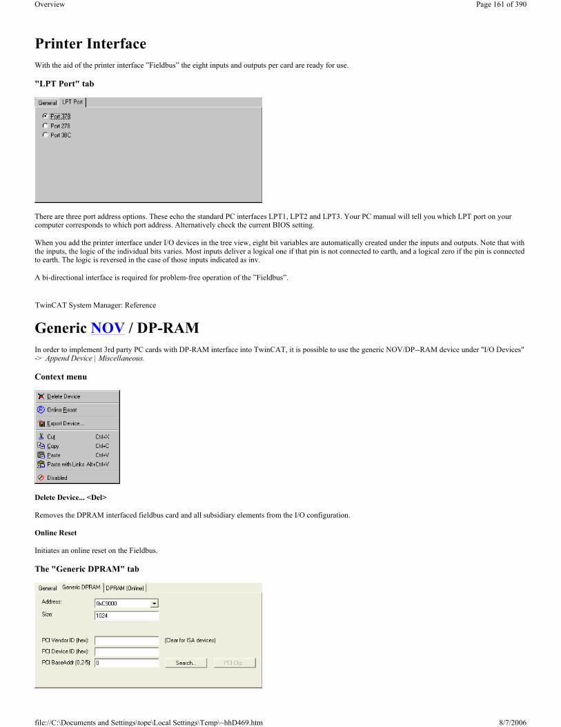
Printer Interface With the aid of the printer interface ”Fieldbus” the eight inputs and outputs per card are ready for use.
"LPT Port" tab
There are three port address options. These echo the standard PC interfaces LPT1, LPT2 and LPT3. Your PC manual will tell you which LPT port on your computer corresponds to which port address. Alternatively check the current BIOS setting.
When you add the printer interface under I/O devices in the tree view, eight bit variables are automatically created under the inputs and outputs. Note that with the inputs, the logic of the individual bits varies. Most inputs deliver a logical one if that pin is not connected to earth, and a logical zero if the pin is connected to earth. The logic is reversed in the case of those inputs indicated as inv.
A bi-directional interface is required for problem-free operation of the ”Fieldbus”.
Generic NOV / DP-RAM In order to implement 3rd party PC cards with DP-RAM interface into TwinCAT, it is possible to use the generic NOV/DP--RAM device under "I/O Devices" -> Append Device | Miscellaneous.
Context menu
Delete Device... <Del>
Removes the DPRAM interfaced fieldbus card and all subsidiary elements from the I/O configuration.
Online Reset
Initiates an online reset on the Fieldbus.
The "Generic DPRAM" tab
TwinCAT System Manager: Reference
Page 161 of 390Overview
8/7/2006file://C:\Documents and Settings\tope\Local Settings\Temp\~hhD469.htm

PCI Slot/Irq: Displays the card address (below 1 Mb for an ISA card) or, in the case of a PCI card the logical PCI slot where the card is located along with the IRQ that has been assigned to it. The IRQ is unused.
Length: It is possible to modify the length of the memory area here, but this should only be done for ISA cards. It is read out automatically for PCI cards.
Search...: This is used to search for the address of the PCI card according to the vendor ID, device ID and the base address.
PCI-Vendor ID: The PCI vendor ID is entered here
PCI-Device ID: The PCI device ID is entered here
PCI BaseAddr: The appropriate memory area is selected here. (A PCI chip can address up to four memory areas, corresponding to the PCI chip's base addresses 2-5. Base address 0 and base address 1 are used for the PCI registers, to which access has not in the past been possible.)
"DPRAM (Online)" tab
See ”Online Display of DPRAM” .
Generic NOV-RAM The Non-Volatile Random Access Memory (usualy called by its acronym NOVRAM, NV-RAM or NOV-RAM) is a specific memory component which can persistently store data in a flash ROM but additionally has no write-cycle limitation. A capacitor, integrated in the NOVRAM chip, supplies the energy for copying recent data from the also internallly integrated RAM to the ROM section during external power-loss situations. The application itself (in this case TwinCAT) writes only to the RAM section of the IC, cyclically.
To use the optional NOVRAM add-on of Beckhoff Fieldbus Cards (e.g. FC3101-0002 / FC3102-0002, FC3151-0002 / FC3152-0002, FC5101-0002 /FC5102-0002, FC5201-0002 / FC5202-0002) under TwinCAT, an additional I/O device called: "Generic NOV/DP-RAM" which can be found under I/O Devices | Miscellaneous, has to be implemented in the I/O configuration.
Note (in ref. to TwinCAT 2.8 only): If the data would be written per I/O refresh of the PLC task to the attached and linked I/O variables underneath the "Generic NOV-RAM" device, a system stop would cause zero-values inside the NOVRAM IC registers! Please see also: Configuration example forTwinCAT 2.8.
Configuration example (TwinCAT 2.9):
Especially for the confiuration of CX1000 controllers it is important, that some variables survive a reboot. Usually no UPS is used along with this kind of devices. New to TwinCAT 2.9 is, that no PLC function blocks are necessary for read and write, and therefore synchronization, of dedicated remanent PLC variables anymore. (Hint: The term "persistent" is not used in this context for a reason!). The below described feature can also be used for the FCxxxx-0002Fieldbus cards, of course.
The following dialog describes the necessary settings for the I/O driver to establish synchronized (remanent) PLC outputs, which survive a reboot.
TwinCAT System Manager: Reference
Page 162 of 390Overview
8/7/2006file://C:\Documents and Settings\tope\Local Settings\Temp\~hhD469.htm

Address: The address as well as the size of the NOVRAM which is to be set here, is usually found automatically after a "Scan for devices".
Auto Init linked PLC Outputs: This Checkbox has to be activated for the implementation of remanent, means, with reboot synchronized variables.
The next step is to define output variables - with the right size and optionally right address offset - underneath 'Outputs' in the treeview (in the above picture these are e.g. the array variables 'Save Data1' and 'Save Data2'). If these outputs are going to be linked to PLC outputs (e.g. declared with AT %Q* ), they will overwrite the initial values of these PLC variables after reboot/start of PLC boot project, automatically. Means, the PLC program will continue with the last stored NOVRAM values in this case.
A special declaration of those PLC variables is not necessary (besides the fact that they need to be declared as located output variables, of course). Especially, a declaration as VAR xxx PERSISTENT or VAR xxx RETAIN, is not allowed in the above context.
Export Data to Disk: Writes the actual content of the NOVRAM to a XML based file on disk. Blocks of 1k (1024 Byte) size are separated within dedicated identifiers inside the XML file. That gives a better overview during reading/manipulating afterwards.
Import Data from Disk: Formerly created NOVRAM XML files (XML files about complete NOVRAM size or even partial) can be read back into NOVRAM. E.g., this can be used to preset the NOVRAM with a "manufacturer data set" at a dedicated address offset prior to machine shipping. Just explore an exported NOVRAM XML file, and it will self-describe its meaning!
Configuration example for TwinCAT 2.8:
In difference to the configuration of an ordinary DP-RAM card with TwinCAT, the data which has to be transferred to the NOV-RAM is not supposed to be linked to I/O variables underneath the "Inputs" or "Outputs" area of the device. Instead, an ADS command (e.g. from PLC) is used for direct writing of this persistent data to the NOV-RAM IC on the Fieldbus card. This means, the configured device has usually no variables underneath the "Inputs" and "Outputs" section in this case. Due to the technical habit of the NOV-RAM component, even cyclical data saving can be implemented.
The following picture shows an example of how to set up a Fieldbus card with NOV-RAM extension. However, the PCI address and other necessary device info is not configured properly in this example.
For the address and data length information to be entered here, please use the displayed data of the already configured fieldbus card (in the sample above "Device 1 (FC5201-0002)" or use the following button:
Search...: With this button, the scan for PCI address corresponding to the Vendor ID, Device ID and Base Address of this card is started.
For additional details see the description of the various Beckhoff Fieldbus cards.
Access to the NOV-RAM via TwinCAT PLC Function Block:
With the help of the Function Block "FB_NovRamReadWrite", which is installed by default with the "TcIOFunctions.lib" library from TwinCAT v2.8 > Build 722, the NOVRAM IC can be read or written directly. Important is the device ID (in this sample it is ID 2, see picture below) of the NOVRAM device inside the TwinCAT System Manager, which can also be read by name (see: IOF_GetDeviceIDByName). For details, see the documentation of the PLC library.
Page 163 of 390Overview
8/7/2006file://C:\Documents and Settings\tope\Local Settings\Temp\~hhD469.htm

DPRAM [Online]
When the TwinCAT is active, the DPRAM of the current fieldbus card, resp. other devices with DPRAM interface, may be read-accessed directly for diagnosis purposes. For further details, please refer to the description of the particular card or the particular device.
System Management Bus (SMB) Newer motherboards possess diagnostic modules via which the temperatures, fan speeds and operating voltages of the PCs can be monitored. These values can be read into TwinCAT with the aid of the ”I/O Device” ”Motherboard SMB (System Management Bus)”. Unfortunately there are currently no unified standards via which these values are made available.
Supports newer motherboards with Intel chipsets. These generally provide access via the PCI-ISA-Bridge PIIX-4. Via the PCI-ISA bridge, access is gained to the register of diagnostic block and the SMB and thereby to the diagnostic data. Individual values can also be determined in the case of other chipsets (if they are have, for example, a LM75 or compatible block). Therefore tests are required to determine which values can be measured on a non-standard board.
The TwinCAT can currently generally recognise the following diagnostic ICs and interpret their data.
� LM78 (National) ( e.g. on ASUS P2B-LS ) � LM78J (National) (e.g. on ASUS P2L97-DS board) � LM80 (National) ( e.g. on QDI BrillantX IS board ) � LM85B or LM85C (e.g. on Intel's D865GLC or D865GBF board ) � W83781D (Winbond) ( e.g. on ASUS P2B and P2B-F boards ) � W83782D (Winbond) ( e.g. on some EPOX boards) � W83783S (Winbond) ( e.g. on ABIT BE6 board ) � W83627HF (Winbond) ( e.g. on EPOX EP-4B2A and EP-M845B board )
Temperature
All ICs belong to the LM78 family. The LM78 is the basic chip with which all other chips are compared. The Winbond ICs have no internal temperature sensor, in contrast to the LM78 ICs. The temperature is generally measured by the motherboard via the internal temperature sensor. The CPU temperature is measured either via a sensor below the CPU or via the Pentium thermal diode. Other temperature sensors can be connected to external connectors on the board. If the CPU temperature sensor is under the CPU a correction variable must be added to the measured temperature. This depends upon the size of the air gap between the CPU and the sensor. If the temperature is measured via the Pentium thermal diode, the measured value must also be corrected. This correction variable depends upon the type of thermal diode. If there is doubt concerning the measured values, the temperature values can generally be monitored in the
TwinCAT System Manager: Reference
TwinCAT System Manager: Reference
Page 164 of 390Overview
8/7/2006file://C:\Documents and Settings\tope\Local Settings\Temp\~hhD469.htm
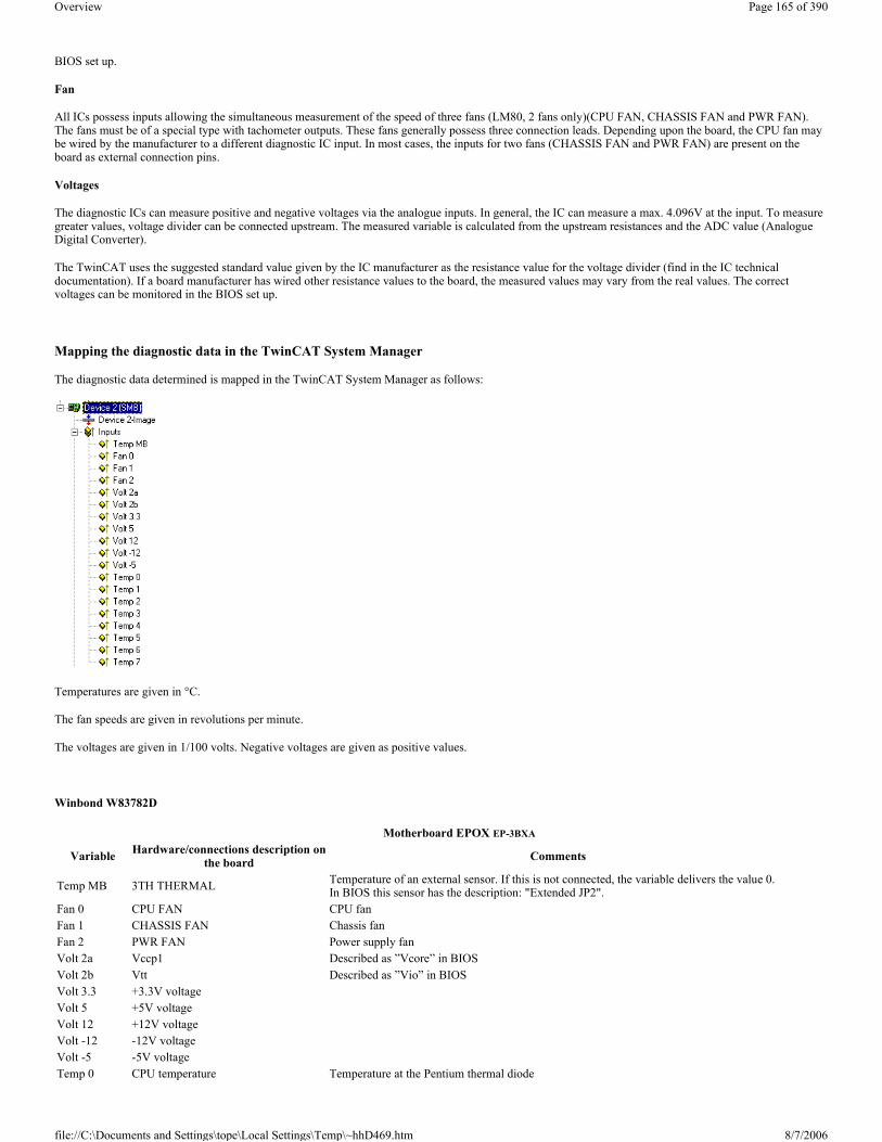
BIOS set up.
Fan
All ICs possess inputs allowing the simultaneous measurement of the speed of three fans (LM80, 2 fans only)(CPU FAN, CHASSIS FAN and PWR FAN). The fans must be of a special type with tachometer outputs. These fans generally possess three connection leads. Depending upon the board, the CPU fan may be wired by the manufacturer to a different diagnostic IC input. In most cases, the inputs for two fans (CHASSIS FAN and PWR FAN) are present on the board as external connection pins.
Voltages
The diagnostic ICs can measure positive and negative voltages via the analogue inputs. In general, the IC can measure a max. 4.096V at the input. To measure greater values, voltage divider can be connected upstream. The measured variable is calculated from the upstream resistances and the ADC value (Analogue Digital Converter).
The TwinCAT uses the suggested standard value given by the IC manufacturer as the resistance value for the voltage divider (find in the IC technical documentation). If a board manufacturer has wired other resistance values to the board, the measured values may vary from the real values. The correct voltages can be monitored in the BIOS set up.
Mapping the diagnostic data in the TwinCAT System Manager
The diagnostic data determined is mapped in the TwinCAT System Manager as follows:
Temperatures are given in °C.
The fan speeds are given in revolutions per minute.
The voltages are given in 1/100 volts. Negative voltages are given as positive values.
Winbond W83782D
Motherboard EPOX EP-3BXA
Variable Hardware/connections description on the board Comments
Temp MB 3TH THERMAL Temperature of an external sensor. If this is not connected, the variable delivers the value 0. In BIOS this sensor has the description: "Extended JP2".
Fan 0 CPU FAN CPU fanFan 1 CHASSIS FAN Chassis fanFan 2 PWR FAN Power supply fanVolt 2a Vccp1 Described as ”Vcore” in BIOSVolt 2b Vtt Described as ”Vio” in BIOSVolt 3.3 +3.3V voltage Volt 5 +5V voltage Volt 12 +12V voltage Volt -12 -12V voltage Volt -5 -5V voltage Temp 0 CPU temperature Temperature at the Pentium thermal diode
Page 165 of 390Overview
8/7/2006file://C:\Documents and Settings\tope\Local Settings\Temp\~hhD469.htm

Winbond W83627HF
Winbond W83781D
Temp 1 RT1 Described as ”System Temperature” in BIOS. A thermal sensor is located on the board (labelled RT1)
Temp 2 to Temp 7 not used
Motherboard EPOX EP-4B2A Motherboard EPOX EP-M845B Motherboard EPOX IP-4GVI63
VariableHardware/connections
description on the board
Comments Hardware/connections description on the board Comments
Hardware/connections description on the
boardComments
Temp MB not used not used not used
Fan 0 CPU FAN CPU fan Fan 3 In BIOS described as Chasis FAN CHASIS In BIOS described
as Chasis FAN Fan 1 CHASSIS FAN Chassis fan (CPU FAN) Fan 1 CPU fan CPU CPU fan
Fan 2 PWR FAN Power supply fan Fan 2 In BIOS described as Power FAN PWR In BIOS described
as Power FAN
Volt 2a Vccp1 Vccp1 Vagp In BIOS described as Vagp
Volt 2b Vtt Vtt Vcore
Volt 3.3 +3.3V voltage +3.3V voltage +2.5V voltage! In BIOS described as Vdimm
Volt 5 +5V voltage +5V voltage +5V voltage Volt 12 +12V voltage +12V voltage +12V voltage Volt -12 -12V voltage -12V voltage -12V voltage Volt -5 -5V voltage -5V voltage -5V voltage
Temp 0 CPU temperatureTemperature at the Pentium thermal diode
CPU temperatureTemperature at the Pentium thermal diode
CPU temperature
Temp 1 RT1
Described as ”System Temperature” in BIOS. A thermal sensor is located on the board (labelled RT1)
TR1
Described as ”System Temperature” in BIOS. A thermal sensor is located on the board (labelled TR1)
TR1
Described as ”System Temperature” in BIOS. A thermal sensor is located on the board (labelled TR1)
Temp 2 to Temp 7
not used not used not used
The EP-M845B board has 4 fan external connection pins. The Winbond IC allows only measurement of the speed of three fans. The fourth fan ( Fan 4) can not be monitored!
Motherboard ASUS P2B or P2B-FVariable Hardware/connections description on the board Comments
Temp MB RT1S Sensor on the board near the Winbond IC (system temperature)Fan 0 CHA FAN Chassis fanFan 1 CPU_FAN CPU fanFan 2 PWR_FAN Power supply fanVolt 2a Vccp1 Volt 2b Vccp2 Volt 3.3 +3.3V voltage Volt 5 +5V voltage Volt 12 +12V voltage Volt -12 -12V voltage Volt -5 -5V voltage Temp 0 JTPWR Connection for an external sensor for mains supply temperatureTemp 1 JTCPU Connection for a sensor for the CPU chiller temperatureTemp 2 to Temp 7 not used
Page 166 of 390Overview
8/7/2006file://C:\Documents and Settings\tope\Local Settings\Temp\~hhD469.htm

LM80
Winbond W83783S and LM75
LM85B or LM85C
Important system requirements:
� The Intel(R) SMBus 2.0 Driver for the ICH5/ICH5-M SMBus Controller-24D3 should be installed and activated; � Other monitoring applications (e.g Intel's Active Monitor) should be deactivated or deinstalled; � The BIOS Option "Fan control" should be deactivated;
Motherboard QDI BrillantX ISVariable Hardware/connections description on the board Comments
Temp MB Internal temperature sensor in the LM80 IC Main board temperatureFan 0 CHASFAN Chassis fanFan 1 CPUFAN CPU fanFan 2 not used Volt 2a not used Volt 2b +1,48V voltage Volt 3.3 +3.3V voltage Volt 5 +5V voltage Volt 12 +12V voltage Volt -12 -12V voltage Volt -5 -5V voltage Temp 0 to Temp 7 not used
Motherboard ABIT BE6 BOSER HS-6237 Version 2.2 BOSER HS-6237 Version 3.0
Variable Hardware/connections description on the board Comments Hardware/connections
description on the board Comments Hardware/connections description on the board Comments
Temp MB CON2Connection for an external sensor for the CPU chiller temperature
not used JP14
Temperature of an external sensor. If this is not connected, the variable delivers undefined value.
Fan 0 FAN2 Connection for a fan near the CPU not used CN2 In BIOS described as
CPUFAN1 speed
Fan 1 FAN3 Connection for a fan near the ISA slot not used CN25 In BIOS described as
CPUFAN2 speed
Fan 2 FAN1 Connection for a fan near the CPU not used CN26 In BIOS described as
CPUFAN3 speed Volt 2a +2V voltage not used Vcore Volt 2b not used not used not used Volt 3.3 +3.3V voltage not used +3.3V voltage Volt 5 +5V voltage not used +5V voltage Volt 12 +12V voltage not used +12V voltage Volt -12 -12V voltage not used -12V voltage Volt -5 not used not used not used
Temp 0 RT1
System temperature. A thermal sensor is located on the board (labelled RT1)
CPU temperatureLM75 temperature sensor
CPU temperature
In BIOS described as CPU1 temperature
To get the real CPU temperature add an offset of ~30°C to the read value!
CPUtemp = TwinCATtemp + 30°C
Temp 1 to Temp 7 not used not used not used
Motherbaord Intel D865GLC or D865GBF
Page 167 of 390Overview
8/7/2006file://C:\Documents and Settings\tope\Local Settings\Temp\~hhD469.htm

Comment
If the variables Temp 0 or Temp 1 deliver a constant value 0xD0, there may be no external sensor connected to the board (open thermal input).
Overview The Beckhoff Bus Terminal system is an open Fieldbus-neutral periphery concept comprising electronic terminal blocks. The head of an electronic terminal block is the Bus Coupler with the interface to the Fieldbus. The following Fieldbusses are currently supported via Beckhoff Bus Couplers under TwinCAT:
Beckhoff Lightbus
Overview
Profibus DP / MC
Overview
Interbus-S
Overview
CANopen
Overview
DeviceNet
Overview
SERCOS Interface
Overview
Ethernet TCP/IP Interface
Overview
Real-Time Ethernet Interface
Overview
Variable Hardware/connections description on the board Comments
Temp MB Ambient temperature sensor (internal to hardware monitoring and fan control ASIC) In BIOS described as "System Zone 1 Tempearature".
Fan 0 CPU FAN CPU fanFan 1 FRONT CHASIS FANFan 2 REAR CHASIS FANVolt 2a Vccp In BIOS described as "Vccp"Volt 2b +1.5V voltage In BIOS described as "+1.5Vin"Volt 3.3 +3.3V voltage Volt 5 +5V voltage Volt 12 +12V voltage Volt -12 not usedVolt -5 not used
Temp 0 Thermal diode, located on processor die Temperature on the Pentium Thermo-Diode. In BIOS described as "Processor Zone Temperature"
Temp 1 Remote ambient temperature sensor In BIOS described as "System Zone 2 Temperature";Temp 2 to Temp 7 not used
TwinCAT System Manager: Reference
Page 168 of 390Overview
8/7/2006file://C:\Documents and Settings\tope\Local Settings\Temp\~hhD469.htm

USB Interface
Overview
Miscellaneous
CX1100-BK
Context menu
Append Terminal ... <Insert>
Adds a Bus Terminal under the Bus Coupler. You will then see the dialogue displayed under Terminal Selection Diagram.
Insert Box Before...
Adds another box above the marked box.
Delete Box... <Del>
Deletes the marked box and its sub-elements from the I/O configuration.
Import Box Before...
Adds another box above the marked box. The description of the new box and its sub-elements are read from a file with the suffix "*.tce". This file is created with the following menu option.
Export Box...
Exports the information from the selected box and the information about its sub-elements into a file with the suffix "*.ioe".
BK20x0 (Lightbus) The Bus Couplers BK20x0 and Bus Terminal Controller BC2000 are used for Beckhoff Lightbus. Those specific properties which distinguish them from other Bus Couplers are described below. For an Overview of all currently supported Lightbus Bus Couplers BK2xx0, please see...
”BK2xx0” tab
2 byte PLC interface: Once selected, one input and output variable for each 2 byte PLC interface is inserted below the coupler.
TwinCAT System Manager: Reference
Page 169 of 390Overview
8/7/2006file://C:\Documents and Settings\tope\Local Settings\Temp\~hhD469.htm

Check Terminals at StartUp: If you select this option (available only when the 2 byte PLC interface is active), compares the configured terminals with those physically present on the coupler during the system StartUp phase. If differences are detected, the system StartUp will be cancelled with a corresponding message.
Check Online Status: If selected, the status byte for the Bus Coupler (Address =0xFF) is evaluated and a corresponding logger entry is created if errors occur.
Show MessageBox in the Event of Error: If selected (only possible when online status checking is activated), any errors are logged and a message box is opened.
Carry Out own K-Bus Update: You can influence the terminal bus update. If this update is not carried out via a C1220 broadcast, it must carry out its own K-Bus update (standard).
After own Data: The update takes place directly after transmission of its own data.
After All Data: The update takes place in the current CDL after all data has been transmitted.
In Extra CDL: The update takes place in an extra CDL (provided the server is set accordingly).
Diagnostic Inputs and Outputs
Each BK2xx0 Bus Coupler has input and output bytes available for diagnostic and settings purposes:
BK3xx0/BC3100 (Profibus) The BK3xx0 Bus Coupler and the BC3100 Bus Controller are used for Profibus. Those specific properties which distinguish them from other Bus Couplers are described below. For an Overview of currently supported Profibus Bus Couplers BK3xx0, see...
”Profibus” tab
Inputs DescriptionTermDiag See also BK2000 manual
Bit 0-7 = Terminal NoBit 8-9 = Channel NoBit 10-11 = Diag CodeBit 12-14 = Diag Code ExBit 15 = Fail
State
Content of the first byte of the word 255 from the process image of the Bus Coupler (see BK2000 manual).Bit 0 = Command ErrBit 1 = Input Data ErrBit 2 = Output Data ErrBit 3 = TimeoutBit 4 = K-Bus Reset FailureBit 6 = K-Bus Overrun (no function at BK2000)
Outputs DescriptionTermDiag See BK2000 manualCtrl0 Content of the first byte of the word 254 from the process image of the Bus Coupler (see BK2000 manual).
Ctrl1 Ctrl1: Content of the second byte of the word 254 from the process image of the Bus Coupler (see BK2000 manual).
TwinCAT System Manager: Reference
Page 170 of 390Overview
8/7/2006file://C:\Documents and Settings\tope\Local Settings\Temp\~hhD469.htm

Stations No.: Each Profibus device requires a unique station number.
Watchdog: Switches on a watchdog function. The time period (in ms) can be set when communication monitoring is actuated. The communication monitoring period should be at least 6 x greater than the cycle time. The minimum value is 10 ms.
PrmData: Allows you to edit the Profibus-specific parameter data (-> BK3xx0 Bus Coupler documentation). The size of the current parameter data is displayed. The PrmData can be entered either in text form (-> PrmData (text)) or occasionally via tabs ”BK3xx0 / BC3x00”.
CfgData: Displays the current configuration data (produced on the basis of added terminals) and their lengths.
The settings DP class 1, DP class 2, DPV1 class 2, Set and Reset slave are only activated for FC310x (-> PROFIBUS DP slaves at FC310x)
”BK3xx0 / BC3x00” tab
2 byte PLC interface: Switches on the 2 byte PLC coupler interface. Register settings in the coupler are then carried out by, e.g. the PLC.
”PrmData (text)” tab
Click on a line to change the current value.
Diagnostic The diagnosis for the PROFIBUS DP slaves at the FC310x is described in a separate section. The diagnosis for other I/O devices is described below.
Input Diagnosis
Page 171 of 390Overview
8/7/2006file://C:\Documents and Settings\tope\Local Settings\Temp\~hhD469.htm

Each Profibus slave box contains two diagnostic input bytes which signal the state of each slave during the running time and which can be linked, for example with the PLC.
BoxState
DpState
PROFIBUS Diagnostic Data
The Profibus diagnostic data sent by a PROFIBUS slave can be read by any TwinCAT program via ADS and/or signalled to any TwinCAT program. In this case, set ADS parameters as follows:
Net-ID: PC Net ID.
Port: 300
IndexGroup: 0x5000 + Device-ID
IndexOffset: Hi-Word: Station Address, Lo Word: 0x100
Length: 6 - 244
The diagnostic data are structured as described in the DP standard.
BK40x0 (Interbus) The BK40x0 Bus Couplers are used for InterBus. Those specific properties which distinguish them from other Bus Couplers are described below. For an Overview of currently supported Interbus Bus Couplers BK4xx0, see...
”BK4xx0” tab
Value Description0 No Error1 Error - more precise description in DpState
Value Description0 No Error - station is exchanging data1 Station deactivated - slave has been deactivated, temporary state during StartUp
2 Station not exists - slave does not reply on the bus -> check whether slave is switched on, whether PROFIBUS plug is in, correct station address or bus cables
3 Master lock - slave is exchanging data with another master -> remove other master from bus or release slave again by other master4 Invalid slave response - incorrect answer from slave, occurs temporarily if slave has ceased data exchange as a result of a local event
5 Parameter fault - check whether Bus Coupler / GSD file is correct, that station address is correct or that UserPrmData settings are correct
6 Not supported - DP function is not supported -> check whether GSD file is correct or whether station address is correct7 Config fault – configuration fault -> check whether the added terminals / modules are correct8 Station not ready -> station starting up, temporarily displayed during StartUp9 Static diagnosis - slave signalling static diagnosis and cannot deliver valid data at present -> check operating state at the slave
TwinCAT System Manager: Reference
Page 172 of 390Overview
8/7/2006file://C:\Documents and Settings\tope\Local Settings\Temp\~hhD469.htm

Identity Code: Displays the identity code for the Bus Coupler. It is calculated dynamically - according to the connected terminals.
Length Code: Displays the length code for the Bus Coupler. It is calculated dynamically - according to the connected terminals.
Installation depth: Displays the installation depth of the Bus Coupler. It is calculated dynamically - according to the hierarchical structure of the InterBus-S.
Diagnostic: Inserts two bytes of diagnostic data into the process image per input and output (see BK4000 manual).
2 byte PLC interface: Inserts two bytes of PLC interface into the input and output process image
Input Diagnosis
Each InterBus-S box contains one diagnostic input byte which signals the status of the current slave during the running time and can be linked, for example with the PLC.
BK51x0/LC5100/IPxxxx-B510 (CANopen) The BK51x0 Bus Coupler and the IPxxx-B510 fieldbus box are installed in the CANopen bus. Those specific properties which distinguish them from other Bus Couplers and/or Fieldbus Box modules are described below. For an Overview of currently supported CANopen Bus Couplers BK51x0, see...
"BK51x0/IX-B510" tab
Variable Value Description
BoxState
0x01 Rec: Reconfiguration0x02 Mod: Module error0x04 W2Err: Error at the W2 interface0x08 W1Err: Error at the W1 interface0x10 W2: W2 interface inactive0x20 W1: W1 interface inactive
TwinCAT System Manager: Reference
Page 173 of 390Overview
8/7/2006file://C:\Documents and Settings\tope\Local Settings\Temp\~hhD469.htm

Node Id: Sets the node ID of the CAN bus device (between 1 and 63 (BK51x0) and/or 1 and 99 (IPxxxx-B510)). This value must comply with the value set at the Bus Coupler and/or at the compact box.
Guard time: Cycle time for the node monitoring (node guarding).
Life time factor: Guard time multiplied produces the watchdog time for the monitoring of the master by the coupler (life guarding). Life guarding is deactivated if the lifetime factor is set to zero.
Inhibit time: Displays the minimum send interval for PDOs (telegrams) with analogue and special signals. If more than digital 64 signals are present, these are also provided with this Inhibit Time.
Event Time: Sets the Event Timer Value for Transmit PDOs. The expiration of this timer is regarded as additional event for the corresponding PDO. Thus the PDO is being sent. If the application event occurs during the event timer period the PDO is sent as well and the timer is reset.
K-Bus Update: Calculates the anticipated duration of a complete update of the terminal bus (according to type and number of connected terminals).
Trans.Type: Gives the Transmission Type for digital / analogue input telegrams. 254 + 255 corresponds to the event-driven transfer, 1 … 240 are synchronous transfer types. For further details see also BK51X0 manual.
Firmware Update: Enables the updating of the coupler firmware via the serial interface (requires KS2000 software package interface cable).
Input Diagnosis
FC510x: Each CANopen fieldbus box node contains one diagnostic input byte (Node State), which signals the status of the current slave during the running time and can be linked, for example with the PLC. In addition a signal is sent via the "Diag Flag" bit informing as to whether the card contains new Diagnostic Information. This can the be read off using ADS READ.
CIF30-CAN: Each CANopen fieldbus box node contains one diagnostic input byte (Box State), which signals the status of the current slave during the running time and can be linked, for example with the PLC. In addition there is a further bit ”DataExchange", which indicates whether the node is exchanging data.
”SDOs” tab
Page 174 of 390Overview
8/7/2006file://C:\Documents and Settings\tope\Local Settings\Temp\~hhD469.htm

SDO inputs sent to the node at StartUp are displayed/managed on this page. Inputs with an object index in straight brackets are automatically created on the basis of the updated terminal configuration. Other inputs can be managed using ”Add”, ”Insert”, ”Delete” and ”Edit”.
”ADS” tab
In order to be able to read and write SDO objects during the running time (e.g. from the PLC), the node (Bus Coupler) can be allocated an ADS port (CIFx0-CAN). The FC510x provides an ADS port at all times for every node since the diagnostic information is transported via ADS. These ports can be used to read and write SDO objects using ADS read requests and/or write requests.
The ADS IndexGroup contains the CANopen object index and the ADS IndexOffset contains the CANopen SubIndex.
CANopen Emergency Object
Some CANopen status data and emergency objects received from a node can be read by any TwinCAT program via ADS and/or signalled to any TwinCAT program. The data structures and addresses distinguish between the FC510x and the CIFx0-CAN.
BK52x0/LC5200 (DeviceNet) The BK52x0 Bus Coupler is used for DeviceNet. Those specific properties which distinguish them from other Bus Couplers are described below. For an Overview of all currently supported DeviceNet Bus Couplers BK52x0, please see...
”BK52x0” tab
MAC Id: Sets the node ID of the DeviceNet participant (between 0 and 63). This value must comply with the value set at the Bus Coupler.
Cycle Time: Sets the cycle time for the I0 connection. This value is added to the Expected Packet Rate (EPR) attributes of the DeviceNet slave and acts as a timeout monitor for IO connections.
Electronic Key: Serves to check the devices within the network at the system StartUp. The electronic key is read from the devices at every system StartUp and compared with the saved configuration.
Polled: Produced/Consumed: Activation of the ”Polling” operating mode, cyclical writing and reading of IO data. Setting of the data content of the data transmitted via the polled IO connections. You can choose from digital data, analogue data or both. The selection depends upon the BK52xx terminal arrangement.
Bit-Strobed: Produced/Consumed: Activation of the ”Bit Strobe” Operating Mode. With a broadcast message all nodes are requested to send their bit strobe message (up to 7 bytes input or status data). Setting of the data content of the data transmitted via the bit-strobed IO connections. You can choose between digital data or diagnostic data.
Change of State / Cyclic:
- Produced/Consumed: Setting of the data content of the data transmitted via the change of state/cyclical IO connections. You can choose from digital data, analogue data or both. The selection depends upon the BK52xx terminal arrangement.
- Change of State / Cyclic: Selecting the Corresponding Operating Mode
- Heartbeat Rate / Scan Rate: In the "Change of State" mode the heartbeat rate gives the cycle time of the cyclical send of the lower-level (i.e. in addition to the event driven) IO data. In the ”Cyclic” operating mode the scan rate gives the cycle time of the IO data send.
Inhibit time: Delay period in the ”Change of State” operating mode inserts this pre-set delay period after a change of state before the IO data send.
TwinCAT System Manager: Reference
Page 175 of 390Overview
8/7/2006file://C:\Documents and Settings\tope\Local Settings\Temp\~hhD469.htm

Acknowledge Timeout: Time before the re-send in the event of faulty acknowledgement of a change of state / cyclical message.
Acknowledge Retry Limit: Maximum number of re-sends until IO connection goes into error mode.
K-Bus Update: Calculates the anticipated duration of a complete update of the terminal bus (according to the number of connected terminals).
Input Diagnosis:
Each DeviceNet fieldbus node contains one diagnostic input byte which signals the status of the current slave during the running time and can be linked, for example with the PLC.
CouplerState
BoxState
DataExchange
”Attributes” tab
Error Code Description Troubleshooting0x00 No error
0x01 IO Error Data exchange between coupler and terminals has faulted Check the IO error LEDs at the coupler, see error code in coupler manual
0x02 Coupler configuration error, devices non-volatile parameters are not valid
Set Manufacturers Setting e.g. with KS2000 or via register communication and reset coupler
0x08 Diagnoses of analog terminals, this feature has first to be activated via KS200 or register communication
Read the terminal diagnoses via explicite messages or via the Bit-Strobe Connection. The Bit is reseted after reading of the diagnosis data
0x80 Fieldbus Error / Idle Mode Check Communication Parameter of the IO Connections. Send correct IO data, Check if the Device is in the Idle mode. The bit is reseted if the device receives valid IO data
Error Code Description Troubleshooting0x02 Station not exists, device is not responding Inspect the device, verify connections, check cabling
0x05 Parameter fault Check explicite access to devices attributes, check object class, instance and attribute id
0x07 Configuration fault Check configuration settings of device0x09 Device is deactivated Check master and device configuration
Error Code Description Troubleshooting0x00 No data exchange between node and master Inspect the field device, verify connections, check cabling0x01 Data Exchange is active
Page 176 of 390Overview
8/7/2006file://C:\Documents and Settings\tope\Local Settings\Temp\~hhD469.htm

DeviceNet attributes/parameters sent to the node at StartUp are displayed/managed on this page. Other inputs can be managed using ”New”, ”Delete” and ”Edit”.
”ADS” tab
In order to be able to read and write attributes during the running time (e.g. from the PLC), the node (Bus Coupler) can be allocated an ADS port. These can be used to read / write attributes via ADS read requests / ADS write requests.
The ADS IndexGroup contains the ClassId and the ADS IndexOffset contains InstanceId and AttributeId (InstanceId * 256 + AttributeId).
Diagnostic data
The DeviceNet status data from a node can be read by any TwinCAT program via ADS and/or signalled to any TwinCAT program.
”Parameter” tab
The parameters are read from the EDS when creating the box. If the system has not started up yet, the EDS default value is always displayed under the value input.
BK7500 (SERCOS interface) The BK7500 Bus Coupler is used for controllers with SERCOS interface. Those specific properties which distinguish them from other Bus Couplers are described below.
The coupler has been designed according to the SERCOS I/O specification, and generates corresponding I/O data channels that can be addressed via IDNs. It should therefore be possible to use it with any controller that conforms to the SERCOS interface. For an Overview of all currently supported SERCOS Bus Couplers BK75x0, please see...
”BK75x0” tab
TwinCAT System Manager: Reference
Page 177 of 390Overview
8/7/2006file://C:\Documents and Settings\tope\Local Settings\Temp\~hhD469.htm

Address: This is used to set the Sercos address with which the coupler announces its presence on the bus.
K-Bus Update: Knowing the attached terminals, the estimated K-Bus run-time is calculated and given.
Strict Mode: The manufacturer-specific parameter P-0-0001 can be used to specify whether the I/O data channels are to be allocated in strict accordance with the Sercos I/O specification, or whether a variation that saves IDNs should be used, since some controllers can only handle a limited number of IDNs in the Master Data Telegram (MDT) or Drive Telegram (AT). The checkbox on this tab only displays the selected mode. It can be modified on the next tab, under Startup, because this parameter is communicated at each start-up (change from phase 2 to phase 3), and the I/O data channels are then assigned accordingly.
Firmware Update...: The coupler's firmware can be updated by means of what is known as a KS2000 cable.
"Startup" tab
Any IDNs can be given (2 and 4 byte values) on the "Startup" file tab, and these are sent to the coupler at the change from phase 2 to phase 3. Further values can be added or deleted here.
"Actual-/Nominal Channel" tab
Page 178 of 390Overview
8/7/2006file://C:\Documents and Settings\tope\Local Settings\Temp\~hhD469.htm

Both the coupler and the TwinCAT System Manager calculate the assignment of the I/O data channels in the light of the connected terminals. The value in P-0-0001, which should normally always be included in the start-up parameters, is considered here, so that both the coupler and the System Manager calculate according to the same rules. The calculated I/O data channels are included in the AT's list of IDNs (S-0-0016, actual channel), or that of the MDT (S-0-0024, nominal channel). In addition to the automatically generated entries, further IDNs can be included in the AT and MDT (as shown in the diagram of the IDN S-0-0364).
"Online" tab
Read and write access to all the coupler's IDNs is possible through the Online tab at run-time from phase 2 onwards.
BK9000 (Ethernet Interface) The Beckhoff BK9000 Bus Coupler can be configured in TwinCAT below a "Virtual Ethernet Interface" or Ethernet Miniport (real-time) I/O device. In reference to the last which is available since TwinCAT v 2.9 is released, an introduction can be found under: Introduction of TwinCAT Real-Time Ethernet.
The following description explains the differences between a BK9000 and other Beckhoff Bus Couplers. The Ethernet coupler communicates in non-real-time applications via TCP/IP or UDP (and ADS as the Application Layer on top of it) with TwinCAT. For an Overview of all currently supported Bus Couplers BK90x0 for Virtual Ethernet Interface, please see...
For an Overview of all currently supported Bus Couplers BK90x0 for Ethernet Miniport (real-time), please see...
Hint: If Real-Time Ethernet and "normal" Ethernet are both used on the same system with two different network adapters, the subnet addresses of these
TwinCAT System Manager: Reference
Page 179 of 390Overview
8/7/2006file://C:\Documents and Settings\tope\Local Settings\Temp\~hhD469.htm

adapters (NICs) must differ! The BK9000 has to be configured with the same subnet address as the Ethernet Miniport adapter, of course (first two quadruples).
"BK9000" Tab
Diagnosis: This checkbox is deactivated for the BK9000.
2 Byte PLC Interface: This checkbox is deactivated for the BK9000.
No Real time Flag: If unchecked, the BK9000 bypasses at all incoming Ethernet frames its internal TCP/IP stack (default if used with Beckhoff TwinCAT Real-Time Ethernet in Run Mode). If, i.e. for configuration purposes in Config Mode sessions the TCP/IP part has to be enabled, this flag may be activated.
K-Bus Update: According to the attached Bus Terminals, the estimated K-Bus update time is calculated and displayed here.
Firmware Update: The firmware update dialog is called by pushing this button. With this function, the most recent firmware version for the BK9000 can be loaded to this device (via LAN or COM port).
Data Exchange: The data exchange with devices can be adapted to their local K-Bus update time and related application. The following description is based on the fact, that the I/O driver resolves an internal cycle counter which is always present.
Scenario: A network contains two Bus Couplers. One Coupler (A) has only a few digital Bus Terminals attached and needs to be updated fast. Another Coupler (B) has analog Bus Terminals and doesn't need to get updated that fast. In that case, at Bus Coupler (B) the
- Divider: would be set e.g. to '4' to force the I/O system to only exchange data with this device in every 4th I/O cycle
and the
- Modulo: factor takes care (in the above case it can be set to value between 0..3) that (B) doesn't get an update in the same cycle (A) gets it.
VLAN Support:
- Enable: Activates the VLAN support (see: IEEE 802.1Q, RFC3518) for the communication with this device. If enabled, the Ethernet frame is getting extended by 4 byte. These extension is called VLAN tag and contains informations about ID and priority for instance
- Priority: A 3 bit VLAN priority value as defined by IEEE 802.1D. Most switches contain two queues, a high and a low priority one. Therefore priorities between 0..3 are assigned to the high priority queue and 4..7 are assigned to the low priority queue at those switch types.
- Id: 12 bit VLAN identifier number as defined by IEEE 802.1Q.
"IP Address" Tab
For further informations about this tab, see -> "IP Address" Tab.
"ADS Commands" Tab
For further informations about this tab, see -> "ADS Command Window".
Diagnosis Inputs:
Each fieldbus module contains status informations which can be linked to TwinCAT (e.g. to to TwinCAT PLC). This status informations are mostly identical
Page 180 of 390Overview
8/7/2006file://C:\Documents and Settings\tope\Local Settings\Temp\~hhD469.htm

at all Beckhoff fieldbus nodes (see CouplerState, MissedCnt)) and are described under -> "Status Information - Beckhoff Fieldbus nodes". Only the input variable BoxState is specific. This variable can contain the values which are described inside the below table. Additionally, each variable status is listed in the corresponding "Comment" field.
Variable "BoxState" at BK9000 couplers underneath a Virtual Ethernet Interface device:
Note (only "Virtual Ethernet Interface" related):
The task cycle time ("Cycle ticks") of the corresponding task should be set to that high, that the variable MissedCnt shows a static value. In a case of doubt it is better to decide for a higher rather than a lower cycle time.
Example: Minimum cycle time with UDP: 30ms
Minimum cycle time with TCP: 50ms
Variable "BoxState" at BK9000 couplers within an Ethernet Miniport (real-time) subnet:
BC9000 (Ethernet Interface) The Beckhoff BC9000 Bus Terminal Controller is to be configured in TwinCAT under a "Virtual Ethernet Interface". The following description explains the differences between the BC9000 and other Bus Couplers or Bus Terminal Controllers.
The Ethernet Bus Terminal Controller communicates via TCP/IP or UDP (and ADS as the Application Layer on top of it)) with TwinCAT. For an Overviewof all currently supported Ethernet Bus Terminal Controllers, please see...
Diagnosis Inputs:
The directly below the Busterminal Controller listed PLC Variables are described under "Data Exchange PC / Bus Terminal Controller".
Each fieldbus module contains status informations which can be linked to TwinCAT (e.g. to to TwinCAT PLC). This status informations are mostly identical at all Beckhoff fieldbus nodes (see CouplerState, MissedCnt)) and are described under -> "Status Information - Beckhoff Fieldbus nodes". Only the input variable BoxState is specific and therefore described below. This variable can contain following values, which are described inside the below table. Additionally, each variable status is listed in the corresponding "Comment" field.
Variable Data Type Value Description
BoxState UINT16
0x0000 No error0x0001 No new Input information0x0002 Outputs disabled (only with UDP)0xnn00 nn = current warning level (only with UDP)
Variable Data Type Value Description
BoxState UINT16
0x0000 No error0x0001 No Inputs received0x0002 Outputs disabled0x0004 No communication0x0008 Old inputs
0x0010 Invalid input length (configured input process variables don't match attached Bus Terminals)
0x0020 Invalid output length (configured output process variables don't match attached Bus Terminals)
TwinCAT System Manager: Reference
Page 181 of 390Overview
8/7/2006file://C:\Documents and Settings\tope\Local Settings\Temp\~hhD469.htm
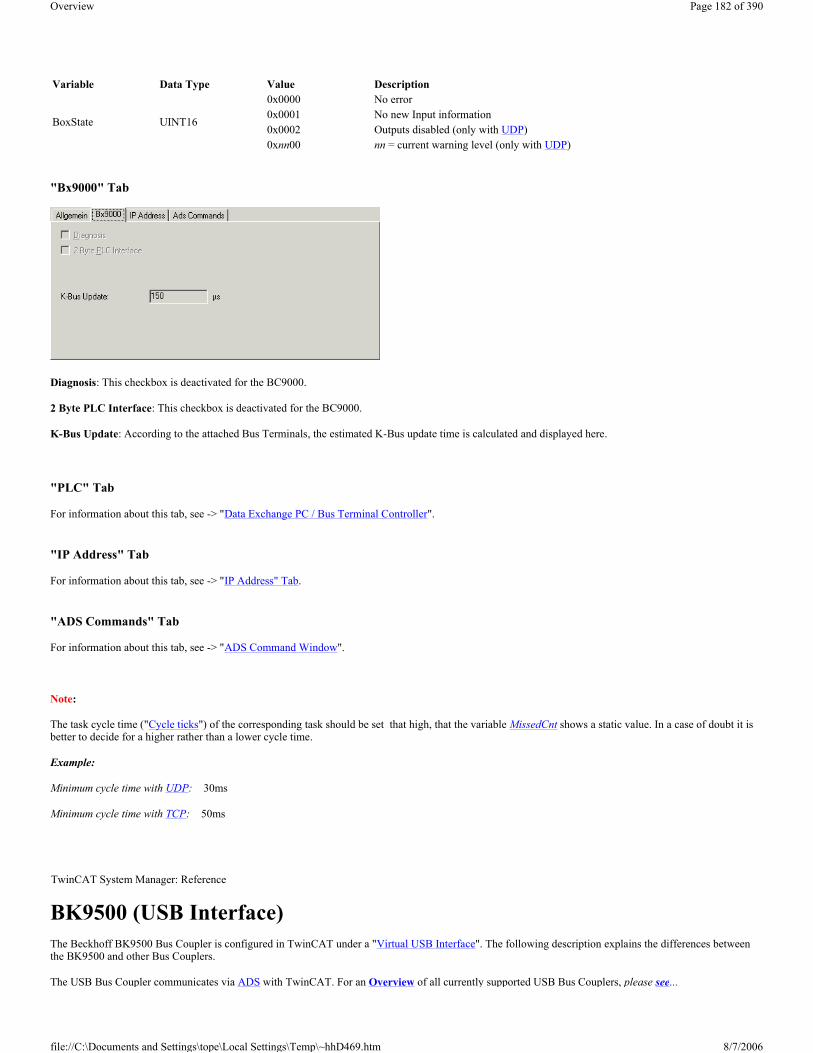
"Bx9000" Tab
Diagnosis: This checkbox is deactivated for the BC9000.
2 Byte PLC Interface: This checkbox is deactivated for the BC9000.
K-Bus Update: According to the attached Bus Terminals, the estimated K-Bus update time is calculated and displayed here.
"PLC" Tab
For information about this tab, see -> "Data Exchange PC / Bus Terminal Controller".
"IP Address" Tab
For information about this tab, see -> "IP Address" Tab.
"ADS Commands" Tab
For information about this tab, see -> "ADS Command Window".
Note:
The task cycle time ("Cycle ticks") of the corresponding task should be set that high, that the variable MissedCnt shows a static value. In a case of doubt it is better to decide for a higher rather than a lower cycle time.
Example:
Minimum cycle time with UDP: 30ms
Minimum cycle time with TCP: 50ms
BK9500 (USB Interface) The Beckhoff BK9500 Bus Coupler is configured in TwinCAT under a "Virtual USB Interface". The following description explains the differences between the BK9500 and other Bus Couplers.
The USB Bus Coupler communicates via ADS with TwinCAT. For an Overview of all currently supported USB Bus Couplers, please see...
Variable Data Type Value Description
BoxState UINT16
0x0000 No error0x0001 No new Input information0x0002 Outputs disabled (only with UDP)0xnn00 nn = current warning level (only with UDP)
TwinCAT System Manager: Reference
Page 182 of 390Overview
8/7/2006file://C:\Documents and Settings\tope\Local Settings\Temp\~hhD469.htm

Diagnosis Inputs
Each fieldbus module contains status informations which can be linked to TwinCAT (e.g. to to TwinCAT PLC). This status informations are mostly identical at all Beckhoff fieldbus nodes (see CouplerState, MissedCnt)) and are described under -> "Status Information - Beckhoff Fieldbus nodes". Only the input variable BoxState is specific. This variable can contain the values which are described inside the below table. Additionally, each variable status is listed in the corresponding "Comment" field.
"BK95x0/CPx8xx" Tab
Dip-Switch: The active dip-switch setting (USB address) of the USB Control Panel has to be edited here. If the BK9500 and his Bus Terminals have been found through ->"Scan Devices", the appropriate address has been set here automatically.
Diagnosis: This checkbox is deactivated at the BK9500.
2 Byte PLC Interface: This checkbox is deactivated at the BK9500.
K-Bus Update: According to the attached Bus Terminals, the estimated K-Bus update time is calculated and displayed here.
Search: If this button is pressed, the Device Handle is searched manually (usually not necessary).
Device Handle: Shows, with activated configuration and started TwinCAT System, the USB Device Handle for this device, which was obtained by the Operating System (and is currently valid).
"ADS Commands" Tab
For information about this tab, see -> "ADS Command Window".
CP68xx / CP78xx (USB Interface) The Beckhoff Control Panel CP68xx and. CP78xx contains an USB interface (incl. integrated USB Hub ) for PC communication to the Special Keys and/or all kind of USB devices, connected to the Control Panel. The Special Keys and USB fieldbus devices communicate with TwinCAT via ADS.
"BK95x0/CPx8xx" Tab
Variable Data Type Value Description
BoxState UINT16
0x0000 No error condition0x0001 No new input information
TwinCAT System Manager: Reference
Typen BeschreibungCP68xx / CP78xx Beckhoff Control Panel with DVI and USB interface
Page 183 of 390Overview
8/7/2006file://C:\Documents and Settings\tope\Local Settings\Temp\~hhD469.htm

Dip-Switch: The actual dip-switch setting (USB address) of the Control Panel with USB interface has to be edited here. If the Control Panel (plus possible Bus Terminals) have been found through ->"Scan Devices", the appropriate address has been set here automatically.
Diagnosis: This checkbox is deactivated at the CP68xx and CP78xx.
2 Byte PLC Interface: This checkbox is deactivated at the CP68xx and CP78xx..
Buttons: The correct number of Special Keys has to be selected here. The default is 27, which is appropriate for the most Beckhoff Control Panels (see also ->"BECKHOFF Knowledge Base").
LEDs: The number of implemented LEDs and/or lamps inside the Special Keys of the Control Panel has to be selected here. Default number is 27, which suits for the most of the Control Panels (see also -> "BECKHOFF Knowledge Base").
K-Bus Update: According to the attached Bus Terminals, the estimated K-Bus update time is calculated and displayed here.
Search: If this button is pressed, the Device Handle is searched manually (usually not necessary).
Device Handle: Shows, with activated configuration and started TwinCAT System, the USB Device Handle for this device, which was obtained by the Operating System (and is currently valid).
"ADS Commands" Tab
For information about this tab, see -> "ADS Command Window".
I/O Variables:
Inputs:
PanelState: This Bit-Array is currently not in use (reserved).
S 1 .. n: Here, the input variables from other tasks (e.g. TwinCAT PLC) can be linked to the Control Panel special keys (S-Keys) or to switches and pushbuttons of the pushbutton extension. Their actual status can be watched here, too.
CouplerState: See "Status Information - Beckhoff Fieldbus nodes".
BoxState: See "BK9500 (USB Interface"
MissedCnt: See "Status Information - Beckhoff Fieldbus nodes".
Note:
USB is specified for segment lengths of up to 5 m (hub to device, resp. next hub). If the MissedCnt value is raising under normal operation conditions, a short commercial off-the-shelf cable (e.g. 3 m) should be used for testing purposes to see whether the problem is related to the segment length of the USB connection.
Page 184 of 390Overview
8/7/2006file://C:\Documents and Settings\tope\Local Settings\Temp\~hhD469.htm

Outputs:
PanelCtrl: With this Bit-Array, the Panel behavior can be controlled. Currently, only the control of the backlight is implemented.
LED 1 .. n: The output variables from other tasks (e.g. TwinCAT PLC) can be linked to the S-Key LEDs or to luminated pushbuttons, respectively their status can be watched, here.
Status Information - Beckhoff Fieldbus Nodes Each Fieldbus module contains state informations which can be linked in TwinCAT to other tasks (e.g. PLC task) for supervision. These state informations are identical at all fieldbus participants for the most part. (see the following CouplerState, MissedCnt) and are therefore described below for all Beckhoff Bus Couplers, Bus Terminal Controllers and Fieldbus Boxes in common. An exception is the specific BoxState, to be found in the corresponding description of the device (e.g. BC9000 under -> "TwinCAT System Manager - Reference").
Diagnosis Inputs
"IP Address" Tab Ethernet components need an unique IP address to be able to communicate. Subsequently, the dialog for the configuration of the specific settings at a Beckhoff Ethernet fieldbus node is described. The following tab appears after marking or adding of such an Ethernet device in / to the System Manager tree.
Variable (Bit of DWORD)
Data Type Value Description
PanelCtrl[5] BOOL0 Display: backlight = ON 1 Display: backlight = OFF
TwinCAT System Manager: Reference
Variable Wert Beschreibung
CouplerState
0x0000 no error condition0x0001 K-Bus error (see additional information in the corresponding Hardware description)
0x0002 Configuration error (e.g. wrong number of configured Bus Terminals, see additional information at the corresponding Hardware description)
Variable Wert BeschreibungMissedCnt numeric Is incremented in every I/O cycle without new (actual) input informations
TwinCAT System Manager: Reference
Page 185 of 390Overview
8/7/2006file://C:\Documents and Settings\tope\Local Settings\Temp\~hhD469.htm

Hostname: The name of the Beckhoff Ethernet node can be edited here.
IP Address: The IP address of the Beckhoff component ( e.g. BK9000) has to be set here.
GetHostByName: From Firmware "B2" on, an IP address for the node (Box) can be obtained from a Windows 2000 DHCP Server (Dynamic Host Configuration Protocol).
Set IP Address: At TwinCAT Real-Time Ethernet nodes, this button can be pushed to set the IP Address conform to the subnet address used by the Ethernet Miniport (real-time) device.
AMS Address: Specifies the AMS-Net ID of this node. This ID is generated automaticaly, derivated from the IP address (2 additional byte values separated by dots (e.g. ".1.1").
BootP: This box can be checked, if the Beckhoff BootP Server has been installed and started on the computer (Requirements: TwinCAT 2.8 or higher).
New MAC Addresses: With a started -> "Beckhoff Bootp Server" and pressing of this button, new found MAC (Media Access Controller) addresses are shown. They are displayed in the field under the button. In the case there is only one new Beckhoff Ethernet device hooked up to the network, only one MAC address is shown. For this MAC address an IP address can be assigned in the above described edit field. With adding of another Beckhoff Ethernet node, this procedure can be repeated on this tab of the new node (Box).
Communication Settings:
TCP: If this radio button is active (default at non-real time devices), the communication is done over TCP (Transmission Control Protocol ). That means, telegram packages from and to the node are exchanged through a safed (confirmed) mechanism.
ADS (available at TwinCAT Real-Time Ethernet nodes): If this radio button is active ...
UDP: If this radio button is active, the communication is done via UDP (User Datagram Protocol ). In difference to the TCP protocol, the single telegram packages are not confirmed by the recipient, nor is the order of the packages approved (means, UDP provides very few error recovery services). Damaged or interchanged telegram packages won't be sent again. The advantage of UDP consists of predictable telegram run times because there is no waiting for a confirmation by recipient. Therefore, UDP is in contrast to TCP/IP the faster communication method, since no TCP/IP stack is necessary for it.
RAW (available at TwinCAT Real-Time Ethernet nodes): If this radio button is active (default at TwinCAT Real-Time Ethernet nodes), the communication to this node is handled via TwinCAT Real-Time Ethernet protocol.
Max. Warning Level: This option is only available in combination with UDP. The maximum value for the error counter can be set here. If this max. value is reached, the master doesn't wait for a response telegram with new inputs from the node. Instead, it sends only read telegrams, based on a higher cycle time to the node.
No Auto Retries: This box can only checked in combination with UDP either. Is this box checked, with reaching of Max. Warning Level an execution of the -> "Online Reset" function is necessary.
"ADS Commands" Tab
For information about this tab, see -> "ADS Command Window".
Overview Following listed devices are used at Beckhoff Lightbus and currently supported by TwinCAT:
Bit7 Bit6 Bit5 Bit4 Bit3 Bit2 Bit1 Bit0fix IP address 0 0 Last digit of IP address e. g. 135.122.57. {Bit5-Bit0}Boot P 0 1 0-5 to ON stores BootP address permanently 0-5 to OFF stores BootP address volatileDHCP 1 0 Settings creates DHCP name
TwinCAT System Manager: Reference
Page 186 of 390Overview
8/7/2006file://C:\Documents and Settings\tope\Local Settings\Temp\~hhD469.htm

Generic 32-bit Box The box type ”Generic 32-bit Box” supports all Beckhoff Lightbus Boxes other than those listed separately. In the case of the Lightbus, 32 bits / 4 bytes of data are sent to the box per telegram (outputs on the fieldbus) and 32 bits of data read in again (inputs on the fieldbus).
The individual bit/byte definitions for the different boxes are taken from the corresponding box manual.
Context menu
Add Box...
Adds another box above the marked box.
Delete Box... <Del>
Deletes the marked box and its sub-elements from the I/O configuration.
Import Box...
Lightbus - Node Type ("Box") Description Restrictions / CommentsBK2000 Standard Bus Coupler BK2010 Economy Bus Couplers BK2020 "Economy plus" Bus Couplers
IPxxxx-B200 Fieldbus Compact Box: Lightbus in/output module, protection class IP67
ILxxxx-B200 Fieldbus Coupler Box: Expandable in/output module with Lightbus interface, protection class IP67
Generic 32-bit BoxThis generic 4 byte telegram is used for all Lightbus Boxes which are not listed by name on the TwinCAT System Manager device list
M1110 16 dig. I/O Box with Lightbus interface (protection class IP65), configurable as "Generic 32-bit Box"
M1200, M1210 Lightbus - Interface module, configurable as "Generic 32-bit Box"
M1400 Box with 32 dig. I/O, configurable as "Generic 32-bit Box"
M1410 Box with 16 dig. I/O, configurable as "Generic 32-bit Box"
M2400 4-channel analogue output Box
M2510 Analog input module (12 bit res., ±10 V, 0-10 V or 4-20 mA configurable)
M3000 Absolute encoder (24 bit resolution, Multi-turn, 4096 steps/rev.) with Lightbus interface
M3100Incremental encoder interface Box (24 Bit resolution) with Lightbus interface (protection class IP65), configurable as a 1-channel M3120 Box
M3120 1 to 4-channel incremental encoder Box
M3200 Incremental encoder (24 Bit resolution) with Lightbus interface, configurable as a 1-channel M3120 Box
M63x0Pushbuttom stations M6310, M6320, M6330 and M6350 with Lightbus interface, configurable as "Generic 32-bit Box"
C1120 Lightbus Interface to Siemens S5 controllers as slave node for TwinCAT configuration
FOX 20 The Fox-20 module has four sockets for digital and analogue sub-modules.
FOX 50 The Fox-50 module is a two channel SSI sensor interface
FOX RK001/002 The Fox-Rk001 and Fox-Rk002 modules are coupling modules which couple one fiber-optical ring with another one (Rk001) or with Profibus (Rk002)
AX2000-B200 Digital Servo drive with Lightbus interface
TwinCAT System Manager: Reference
Page 187 of 390Overview
8/7/2006file://C:\Documents and Settings\tope\Local Settings\Temp\~hhD469.htm

Adds another box above the marked box. The description of the new box and its sub-elements are read from a file with the suffix "*.tce". This file is created with the following menu option.
Export Box...
Exports the information from the selected box and the information about its sub-elements into a file with the suffix "*.ioe".
Variables
Beneath the box, four bytes each in/outputs are automatically defined which are addressed/linked either as bytes or as individual bits.
”32 bit” tab
The individual variables can be linked at the same time for all variables via the ”32 bit” tab. You can of course still create the links using the context menu or the tab view for each variable.
D0 Input...: Opens the link dialogue for the first input byte / for a bit of the first input byte if you have selected bit-wise mode. If linking by bits you can select the relevant bit.
D1 Input...: ditto.
M2400 The M2400 is an analogue output box with up to four channels, which also has two digital data bytes. The box jumpers determine whether the data bytes function as input or output bytes (see M2400 manual). If the box has less than four analogue channels, the corresponding DACs are not linked.
Note:
If the box is linked to several tasks (e.g. DACs with NC and data bytes with PLC), the data telegram is only created for the higher priority task. This is important in particular during commissioning if, e.g. only the PLC is running.
Context menu
Add Box...
Adds another box above the marked box.
Delete Box... <Del>
Deletes the marked box and its sub-elements from the I/O configuration.
Import Box...
Adds another box above the marked box. The description of the new box and its sub-elements are read from a file with the suffix "*.tce". This file is created with the following menu option.
Export Box...
Exports the information from the selected box and the information about its sub-elements into a file with the suffix "*.ioe".
Variables
TwinCAT System Manager: Reference
Page 188 of 390Overview
8/7/2006file://C:\Documents and Settings\tope\Local Settings\Temp\~hhD469.htm

Four 16 bit output variables with the descriptors DAC 1 to DAC 4 are created and can be linked. Both data bytes are located correspondingly under inputs and/or outputs. The orientation is entered in the ”Data Bytes” tab. The data bytes can be accessed as both bytes and bits.
"DAC's" tab
The individual variables can be linked for all variables via the ”DACs” and ”Data Bytes” tabs. You can of course still create the links using the context menu or the tab view for each variable.
DAC 1...: Opens the link dialogue for the first analogue output channel.
DAC 2...: ditto...
”Data Bytes” tab
D 2...: Opens the link dialogue for the first data byte (D2 in the telegram).
Input / Output: Determines whether the data byte is treated as an input or output (must correspond to the hardware setting).
By bytes / by bits: Determines whether the link dialogue is opened for the whole byte or for individual bits.
M3120 The M3120 is an incremental encoder box with up to four channels. It is available in four different versions with one, two, three and four channels. When inserting the box you need to choose the right type, since each channel represents in logical terms a single box. Therefore in the event of an error input, the total number of boxes changes.
The M3120 channels are called INC 4, INC 3, INC 2 and INC 1; these descriptions correspond to the label on the box!
Variables
TwinCAT System Manager: Reference
Page 189 of 390Overview
8/7/2006file://C:\Documents and Settings\tope\Local Settings\Temp\~hhD469.htm

Each channel of the M3120 has four variables, two input variables and two output variables:
1. Status byte (8 bit input variable), displays the current status of that channel. 2. Value (24 bit input variable), delivers the current counter status/latch value. 3. Control byte (8 bit output variable) allows you to, e.g. toggle between counter and latch variable 4. Set value (24 bit output variable) to set the counter value.
Please refer to the M3120 manual for further details.
Fox20 The Fox-20 module has four sockets for digital and analogue sub-modules (the first socket is for analogue sub-modules only).
Variables
All possible variables are displayed in the tree. The variables can/must be linked depending on what is plugged into the Fox-20 module. If an analogue sub-module has been plugged into a socket, the word variables Modx_Chny in the input and/or output area can be linked. In which x stands for the sub-module socket and y for the channel corresponding to that socket.
In the case of digital sub-modules (one channel only) the bit variables must be linked below the Modx_Chn1 variables.
The links tell the TwinCAT System Manager whether the fibreoptic telegram is for a digital or an analogue sub-module.
Fox50 The Fox-50 module is a two channel SSI sensor interface.
Variables
TwinCAT System Manager: Reference
TwinCAT System Manager: Reference
Page 190 of 390Overview
8/7/2006file://C:\Documents and Settings\tope\Local Settings\Temp\~hhD469.htm

In the tree, one status byte and one 24 bit value is inserted per channel. These can be linked manually or from the NC configuration (FOX50 encoder type).
FoxRk001/002 The Fox-Rk001 and Fox-Rk002 modules are coupling modules which couple the fibreoptic ring with another fibreoptic ring (Rk001) or with a Profibus (Rk002).
Variables
(RK001 with 4 words each)
When inserting the module you will be requested to give the required number of input and output words (max. 254 Rk001 and/or 16 Rk002).
The tree will then created that number of variables.
In the case of the Rk001 an IdentNo word is also added to each input and output area, which can be exchanged with the word 0xFE in the module.
AX2xxx-B200 Drive The Beckhoff AX2000 and AX2500 drive is available with different (in the case of AX2000 optional) fieldbus interfaces. The following dialogs are for an AX2000 with Beckhoff Lightbus interface (e.g. part no.: AX2003-B200). Nevertheless, the dialogs and descriptions is also suitable for AX2500, since these drives are fully software compatible to the AX2000.
"AX2000" Tab
TwinCAT System Manager: Reference
TwinCAT System Manager: Reference
Page 191 of 390Overview
8/7/2006file://C:\Documents and Settings\tope\Local Settings\Temp\~hhD469.htm

State: The variable "State" of the AX2000-B200 Servo drive can be linked to a variable of another process image (e.g. with TwinCAT PLC) here.
K-Bus Update: Optionally, Beckhoff Bus Terminals can be hooked up to an AX2000 drive. Based on the attached terminals, the K-Bus update time is calculated and displayed here.
Firmware Update: The Firmware of the -B200 Lightbus interface can be updated through the serial COM port of the PC, if this button is pressed.
Firmware Version: After pressing of this button, the current Firmware version of the -B200 Lightbus interface is read and displayed in the field next to it..
2 Byte PLC Interface: After checking of this box, input and output variables for the PLC Interface will be inserted below the drive symbol in the tree view.
Check Terminals at Startup: Checks during initialization phase, whether configured Bus Terminals (optional) are really connected to the K-Bus extension of the drive). It has no function at drives without K-Bus extension.
Check State while Online: Evaluates cyclical the -B200 "State" variable if checked. On error condition, a message will be brought to the System Manager Logger View.
Show Message Box on Error: Fires on error conditions, additionally to the Logger View and Event viewer entry, a Message Box to the surface.
Generate own K-Bus update: Activates own des K-Bus cycle if 0x30 telegram arrives to the Lightbus interface and the master card sends no broadcast telegram. This checkbox is activated by default at AX2xxx-B200 drives.
After own data: The K-Bus update is done directly after own data was sent.
After all data: The K-Bus update is done after all data of the current CDL were sent.
Variable I/O Data: From Firmware version "B5" of the -B200 Lightbus interface for the AX2000 drive on, the Lightbus telegram structure to the drive can be optimized (at AX2500 drives at all Firmware revisions). To allow the optimization, this and the following checkbox have to be activated. For compatibility reasons, this checkbox "Variable I/O Data" is not checked by default, when a new AX2000 device is added to the System Manager configuration.
Optimized Telegram Count: See: Variable I/O Data.
Save Configuration to Flash: If this box is checked, the configuration is going to be saved to the Flash memory of the drive with each TwinCAT start (only, if at least one parameter has changed).
Reset Config and Clear Flash: The Flash memory of the drive can be cleared by pressing this button.
"ADS/AMS" Tab
For further informations about this tab, see: "ADS/AMS Settings at I/O Devices".
"Online" Tab
For further informations about this tab, see: "AX2xxx Drive Tab - Online".
"Actual Channel" Tab
For further informations about this tab, see: "AX2xxx Drive Tab - Inputs"
"Nominal Channel" Tab
Page 192 of 390Overview
8/7/2006file://C:\Documents and Settings\tope\Local Settings\Temp\~hhD469.htm

For further informations about this tab, see: "AX2xxx Drive Tab - Outputs"
Diagnosis Inputs (optional)
If the variables DriveError, DriveState (alternatively DriveState2 and DriveState3) are added to the Variable I/O Data (described above), they can be used for diagnosis purposes (e.g. if they are linked to a TwinCAT PLC process image, they can be evaluated inside the PLC run-time system).
For further informations about the error and warning codes of the AX2xxx drive, see: "AX2xxxx Drive - Status and Error Codes"
AX2xxx Drive Tab - Inputs "Inputs" Tab
If the the option Variable I/O Data is checked on the "AX2000" tab, additionally the tabs "Inputs" and "Outputs" appear at the AX2xxx drive device. On "Inputs", the optional input variables which may be required in the cyclical drive telegram at some applications (and which appear inside the "Inputs" area below the drive symbol in the tree view), can be added or removed manually.
Append: Calls the dialog described below for selecting the variable incl. their data type and appends the variable in the tree view of the device.
Insert: Calls the dialog described below for selecting the variable incl. their data type and inserts the variable at a specified position in the tree view of the device.
Delete: Removes the selected variable from the tree view of the drive inputs (and from the Lightbus telegram).
Edit: Calls the dialog below for editing a variable.
TwinCAT System Manager: Reference
Page 193 of 390Overview
8/7/2006file://C:\Documents and Settings\tope\Local Settings\Temp\~hhD469.htm

Offs (Byte): Automatically assigned offset for the variable in the AX2xxx drive telegram.
(Bit): Bit-offset of variable.
Swap Word: Word swap in 32bit telegrams for passing values to process image (active by default).
Bit Addr: Points to the bit address of a variable for the automatic masking.
Name: Shows the name of the selected variable. If a different variable name should show up in the drive tree view, it can be edited here.
OK: Accepts the changes of the AX2xxx drive telegram.
Cancel: Closes the dialog without changing the telegram.
Important:
If the added variables should be linked with a not NC-SAF_Task , this task has to be used with a lower priority ( priority number higher)
List of input variables
List of output variables
Name Data type/value range Description
DriveError UDINT see DriveError
ActualTorque
ARRAY 0..1 of UINT16
0..3280 -> 0..IPEAK
current current / torque of AX2000-B200 or B900. The given value refers to the set surge current of the current controller. ASCII command IPEAK. Calculation of the torque by multiplication with the torque constant of the used motor.
ActualVeloUDINT / u/min * 139,8
current velocity
ActualPos UINT16 / 0..FFFF current position. Via hardware counter 16 Bit at OPMODE = 0.
DriveState UDINT see DriveState
DriveStateErrBit BIT DriveState.7 drive error
DriveStateAmplEnableBitBIT DriveState.6 output stage enabled
DriveStateInitReadyBit BIT DriveState.2 ready for operation
ActualPosEx UDINT contains position value of absolute encoder (built in the motor) (e.g. EnDAT, Hiperface). Depends on the parameter PRBASE
PulseConnect UINT16 untreated actual position in increments without SI- unitsLatchPos UINT16 latched positionLatchValid Byte Latch occursLatchPosValidBit LatchValid.0 positive latchLatchNegValidBit LatchValid.1 negative latch DigInputBit n BIT Digital input 1,2,3,4
AnaInput nUINT16 / 10V -> 404 Dig
Monitor output
Button n BYTE dispaly of button under 7 segment display
Page 194 of 390Overview
8/7/2006file://C:\Documents and Settings\tope\Local Settings\Temp\~hhD469.htm

AX2xxx Drive Tab - Outputs "Outputs" Tab
This tab is for the equivalent tasks as the tab "Inputs" but it is responsible for manipulating the output variables in the AX2xxx drive telegram instead. The process of adding or removing variables is identical here to the procedure under "Inputs".
For further informations, see: AX2xxx Drive Tab - Inputs.
AX2xxx Drive Tab - Online "Online" Tab of AX2000-B200 of AX2000-B900
The ASCII Objects of the AX2xxx drive are listed on this tab with current values (values are determined during tab opening). See also: Refresh
Refresh: To update the values shown in the listing, press this button.
Name Data type/value range Description
DriveCtrl 0..3 UDINT controller control bytes
DriveCtrlEnable DriveCtrl1.0 1-> output stage enabled 0-> output stage disabled. A negative flank of this bit 0 creates a reset on the controller.
DriveCtrlDigCurrent DriveCtrl0.1 DriveCtrlEnableLatchPos DriveCtrl3.0 Enable positive latchDriveCtrlEnableLatchNeg DriveCtrl3.1 Enable negative latchNominalTorque UDINT Default set value of current at the digital torque interface (OPMODE 2)
NominalVelo24UINT24 / u/min * 139,8
Set velocity, optimised to 24 bit
NominalPos UDINT Set position. Depends on the settings of parameter PRBASE CurrentLimiting UINT16 Default set value current at the digital speed frequency interface (OPMODE 1) as auxiliary operation modeDigOutputBit 1& 2 BIT digital monitor output
AnaOutput 1 & 2 UINT16 / 1,25mV/dig analog monitor output
NullImpulse BIT zero point of resolverLED-Control BYTE If a value unequal zero is entered, the interface to the 7 segement display is active.LEDs 1,2,3 BIT Value for the three 7 segment displays
TwinCAT System Manager: Reference
TwinCAT System Manager: Reference
Page 195 of 390Overview
8/7/2006file://C:\Documents and Settings\tope\Local Settings\Temp\~hhD469.htm

Drive to Disk: Saves parameters with currently displayed values to disk. The file is stored in ASCII format and has the file extension *.axp.
Disk to Drive: Loads the parameter values of an previously stored *.axp file into the AX2xxx drive.
CLRFAULT: Calls the command for clearing of some defined drive errors (see AX2xxx manuals supplied on "Beckhoff Drive Technology" CD, also).
COLDSTART: Call the command for a initialising the drive (the Firmware) once again. Previously appeared errors are cleared then.
SAVE (EEPROM): Saves the downloaded parameters to the EEPROM of the drive. Therefore, the previous parameter changes will be active even after a coldstart of the drive.
Send String: Sends a single command (edited in the field right next to it) with a request for a parameter value to the drive. The feedback will be displayed in a message box after arrival.
Example:
If you enter the string FW, it would display e.g. the current drive Firmware version.
Example:
If you enter the string In3mode 2 the function of the third digital input (PSTP) will be changed.
AX2xxx Drive - Status and Error Codes At AX2xxx-B200 drives, the variables DriveError, DriveState and Status are added via Variable I/O Data.At AX2xxx-B900 drives, the I/O variables DriveState2 and DriveState3 appear by default under "Inputs", but the DriveError variables are to be added manually. Please find additional info under: AX2xxx Drive Tab - Inputs.
These input variables can be used for diagnosis purposes (e.g. if they are linked to a TwinCAT PLC process image, they can be evaluated inside the TwinCAT PLC run-time system).
In any case, the error and warning codes are displayed on the 7-segment display of the AX2xxxx drive (see column: "AX2xxx Display").
The below error messages and warnings could appear:
TwinCAT System Manager: Reference
Variable Data Type Value AX2xxx Display
Designation
0x00000001 F01Error heat sink temperature is set, if the current heat sink temperature (TEMPH) goes beyond the max. allowed value (MAXTEMPH).
Error overvoltage
Page 196 of 390Overview
8/7/2006file://C:\Documents and Settings\tope\Local Settings\Temp\~hhD469.htm

DriveError
(can also be linked byte-wise with help of the variables DriveError0, DriveError1, DriveError2 and DriveError3)
The equivalent ASCII command is:
ERRCODE *resp. ERRCODE
UINT32
0x00000002 F02 is set, if the voltage inside the DC-link circuit goes beyond the max. allowed value (VBUSMAX).
0x00000004 F03
Error position controller (drive) if drive internal position controller is used (OPMODE=6/SERCOS) and the lag distance is too high. Means, if in the above case the max. revolutions per minute value goes beyond (VLIM / VLIMN).
0x00000008 F04 Feedback error (Resolver) is set, if the amplitude of the resolver / encoder signals goes below the min. value.
0x00000010 F05Error undervoltage is set, if the voltage inside the DC-link circuit goes below the min. allowed value (VBUSMIN).
0x00000020 F06 Error motor temperature is set, if the resistance of the motor thermoelement (TEMPM) goes beyond the max. allowed value (MAXTEMPM).
0x00000040 F07 Internal supply voltage (aux. voltage) not ok..
0x00000080 F08 Speed error is set, if the current motor revolution per minute value (V) goes beyond the max. allowed value (VOSPD).
0x00000100 F09 Error EEPROM is set, if the the read/write process with the serial EEPROM fails. It can happen because of a bad EEPROM or wrong checksum. In the second case, an additional try to save to EEPROM, may help.
0x00000200 F10 Reserved0x00000400 F11 Brake error
is set, if the brake input notices an error (e.g. brake not connected). 0x00000800 F12 Reserved0x00001000 F13 Error ambient temperature
is set, if the ambient temperature (TEMPE) goes beyond the max. allowed value (MAXTEMPE)
0x00002000 F14 Amplifier error Following problems could cause the error: Line output grounded to earth, motor short circuit or ballast circuit shorted.
0x00004000 F15 Error I2Tmax exceeded is set, if I2T is at 115% (at FOLDMODE=0) respectively 105% (at FOLDMODE=1).
0x00008000 F16 Supply voltage not correct is set, if 2 or 3 phases of supply voltage are missing. For additional information see manuals supplied with AX2xxx drive, also.
0x00010000 F17 Error A/D Converter
is set, if offsets of drive current values are too high during startup. 0x00020000 F18 Ballast transistor error
with bad ballast transistor respectively preselection of "external ballast resistor" in combination with connected internal ballast resistor, this error is going to be set.
0x00040000 F19 Error missing phase.
at PMODE=2. 0x00080000 F20 Slot Error
This error condition is generated, if there are problems with present slot expansion card (e.g. AX2xxx-B200). This error message is depending on the used expansion slot card type. It usually points to a faulty interface hardware.
0x00100000 F21 PROFIBUS Handling Error
This error can only happen in combination with the use of a Profibus expansion card (part no.: AX2xxx-B310).
0x00200000 F22 Drive circuits are grounded to earth potential (PE)0x00400000 F23 Error in CAN communication
This error message BUSOFF is generated directly by level 2 of the internal CAN controller.
0x00800000 F24 Error Watchdog
This error is displayed, if the telegram update time exceeded the value set in EXTWD.0x01000000 F25 Error in commutation
At this error message, the motor has a commutation problem (uncontrolled motor behavior). The commutation treshold value can be changed under VCOMM, the unit is RPM (rounds per minute).
Page 197 of 390Overview
8/7/2006file://C:\Documents and Settings\tope\Local Settings\Temp\~hhD469.htm

0x02000000 F26 Error in calibration (hardware limit switch)
is defined by REFLS.0x04000000 F27 Error AS-Option
is set, if amplifier was enabled during activation of the optional starting inhibiting circuit (part no.: AX20xx-yyyy-0001).
0x08000000 F28 Error "external position setpoint offset"
External position setpoint offset beyond limit. 0x10000000 F29 SERCOS error0x20000000 F30 SERCOS emergency stop timeout0x40000000 F31 Reserved0x80000000 F32 System error
shows an internal error. This error is generated at drive startup, if system check didn't succeed during initialization. For further information, see detailed AX2000 / AX2500 manuals supplied with drive.
DriveState
(can also be linked byte-wise with help of the variables DriveState0, DriveState1, DriveState2 and DriveState3 )
The equivalent ASCII command is:
DRVSTAT
UINT32 0x00000001 n01 Warning I2T- threshold value exceeded
is set, if I2T goes beyond the limit set under I2TLIM.0x00000002 n02 Warning ballast circuit
is set, if the current regen circuit exceeds the threshold value set under PBALMAX. The warning is cleared as soon as the value goes below PBALMAX.
0x00000004 n03 Warning lag-distance exceeded
is set, as soon as the distance between the set position and the position controller trajectory exceed the set value PEMAX. It can be deleted with the command CLRFAULT.
0x00000008 n04 Watchdog warning
is set, if the fieldbus watchdog time EXTWD was exceeded. 0x00000010 n05 Warning: At least one supplied phase is missing
is displayed, if not all three phases of supply voltage are supplied. 0x00000020 n06 Warning: Software limit switch 1 below minimum
is set, if the value of the software limit switch 1is below SWE1.
In addition, the warning is set, if a motion task was started with a target position below the value specified in drive object SWE1. The warning message is cleared as soon as SWE1 is exceeded and a positive speed setpoint value is passed over (means, when a start command with valid position values is supplied).
0x00000040 n07 Warning: Software limit switch 2 beyond maximum
is set, if the value of the software limit switch 2 is beyond SWE2.
In addition, the warning is set, if a motion task was started with a target position beyond the value specified in drive object SWE2. The warning message is cleared as soon as SWE2 stays below and a negative speed setpoint value is passed over (means, when a start command with valid position values is supplied).
0x00000080 n08 Warning: Wrong start command
is set, if it was tried to start an undefined (missing checksum) motion task. The warning is cleared automatically if a valid start command is supplied.
0x00000100 n09 Warning: Reference point (calibration) not set
is set, if a motion task was initiated without a calibration/homing done before. 0x00000200 n10 Warning: PSTOP activated
is set, if hardware limit switch PSTOP (stop switch in positive direction) is activated. Warning is cleared as soon as the limit switch is released again.
0x00000400 n11 Warning: NSTOP activated
is set, if hardware limit switch NSTOP (stop switch in negative direction) is activated. Warning is cleared as soon as the limit switch is released again.
0x00000800 n12 Warning: Default motor data loaded is set during drive startup, if the motor ID of the serial EEPROM and the motor ID of the SIN/COS encoder don't match.
0x00001000 n13 Slot warning (I/O card) is set, if there is a disfunctionality with the optional I/O card (part no.: AX2090-I001),
Page 198 of 390Overview
8/7/2006file://C:\Documents and Settings\tope\Local Settings\Temp\~hhD469.htm

which is for starting of predefined (inside drive) motion tasks.0x00002000 n14 Recognition of MPHASE (FBTYPE=7)0x00004000 n15 Warning: Wrong VCT-Entry selected (table error)
is set, when a wrong VCT entry is selected and to be activated. 0x00008000 n16 Warning n17 .. n31 active
is set, if one or several warnings in the range between n17.. n31 are active 0x00010000 Motion task active
Is set, if a motion task is started (motion task, jog or homing move). Is cleared, if the action is finished or a STOP - command is executed
0x00020000 Reference point is set.Is set, if the homing move was done or a absolute encoder feedback device is used. Is cleared if a homing move is started
0x00040000 Home switch Is high, if the homing switch is closed, otherwise low.
0x00080000 In-Position Is high, if the distance between the target position and the actual position is smaller than PEINPOS, otherwise low. When several motion tasks are tied together, only the last motion task enables this bit.
0x00100000 Position latch occurred (positive edge) Is set, if a positive edge at the latch input (Input2 with IN2MODE=26) was detected. Is cleared, if the lachted position was read (LATCH16/ LATCH32).
0x00200000 Position register 0 Is high, if the configured condition (SWCNFG2, SWE0, SWE0N) is true, otherwise low (see SWCNFG2).
0x00400000 Position register 1 Is high, if the configured condition (SWCNFG, SWE1, SWE1N) is true, otherwise low (see SWCNFG).
0x00800000 Position register 2 Is high, if the configured condition (SWCNFG, SWE2, SWE2N) is true, otherwise low (see SWCNFG).
0x01000000 Position register 3 Is high, if the configured condition (SWCNFG, SWE3, SWE3N) is true, otherwise low (see SWCNFG).
0x02000000 Position register 4 Is high, if the configured condition (SWCNFG, SWE4, SWE4N) is true, otherwise low (see SWCNFG).
0x04000000 Initialization phase finished Is set, if the initialization phase of the drive is finished (takes about 15s).
0x08000000 Position register 5 Is high, if the configured condition (SWCNFG2, SWE5, SWE5N) is true, otherwise low (see SWCNFG2).
0x10000000 Motor stand still message Is high, if the actual motor velocity is lower than the threshold VEL0, otherwise low.
0x20000000 Safety relais selected Is high, if the safety relay of the AS- option (part no: AX20xx-yyyy-0001) is switched on, otherwise low.
0x40000000 Output stage enabled Is high, if the soft- and the hardware enable is present, otherwise low.
0x80000000 Drive is in error condition Is set, if the drive has a fault (output stage is disabled, error number is displayed). The command ERRCODE gives the error in plain text. The bit is cleared, if the drive is reset or the command CLRFAULT is send.
State UINT8 0x01 Command error from AX2xxx-Bx00 interface.
0x02 Error in input data from AX2xxx-Bx00 interface.
0x04 Error in output data from AX2xxx-Bx00 interface.
0x08 Timeout from AX2xxx-Bx00 interface.
0x10 Error K-Bus Reset from AX2xxx-Bx00 interface.
Page 199 of 390Overview
8/7/2006file://C:\Documents and Settings\tope\Local Settings\Temp\~hhD469.htm

ASCII Object Description The Beckhoff AX2000 and AX2500 drive contains numerous ASCII objects to read or manipulate internal parameters. These ASII objects can be accessed fieldbus-independently via ASCII commands in read- and some of them even in write mode. Some networks are using the ASCII commands during initialization of the axes through TwinCAT (e.g. Beckhoff Lightbus or Real-Time Ethernet). However, not all parameters are relevant in combination with TwinCAT NC-PTP or TwinCAT NC-I. In any case, the support of the individual command depends on the Firmware revision of the drive (=> VER)!
A listing of the supported commands can be found under: AX2xxx Reference - ASCII Object Description.
At drives used under SERCOS, similar parameters are defined according to the IEC 61491 standard. For a description of the Sercos IDent Numbers supported by AX2000 respectively AX2500, please refer to: AX2xxx-B750 Reference. If a dedicated IDN matches the function of one of the ASCII objects, it is named in the table of the correlating IDN (for example: S-0-0030 == VER).
Overview Following slave devices with Profibus interface are currently supported by TwinCAT:
(Hint: Via the also listed generic "GSD Device", all Profibus slaves with valid GSD/GSE files are additionally supported, of course!)
TwinCAT System Manager: Reference
TwinCAT System Manager: Reference
Profibus - Node Type ("Box") Description Restrictions / CommentBK3000 Bus Coupler (max. 1.5 MBaud) BK3100 Bus Coupler (max. 12 MBaud) BK3010 Economy Bus Coupler (max. 1,5 MBaud) BK3110 Economy Bus Coupler (max. 12 MBaud) BK3120 "Economy plus" Bus Coupler (max. 12 MBaud) BK3500 Bus Coupler (fibreoptical, max. 1.5 MBaud)
BK3520 "Economy plus" Bus Coupler (fibreoptical, max. 12 MBaud)
LC3100 Low-cost Bus Coupler (max. 12 MBaud)
BC3100 Bus Terminal Controller with integrated PLC (max. 12 MBaud)
IPxxxx-B310 Fieldbus Compact Box: Profibus in/output module, protection class IP67 (max. 12 MBaud)
ILxxxx-B310 Fieldbus Coupler Box: Expandable in/output module, protection class IP67 (max. 12 MBaud)
ILxxxx-C310 Fieldbus PLC Box: Coupler Box with integrated PLC, protection class IP67 (max. 12 MBaud)
AX2xxx-B310Beckhoff AX2000-B310 or AX2500-B310 drive as Profibus DP slave, supported through special PLC Function Blocks
AH200x Beckhoff AH2001 or AH2003 hydraulic controller with Profibus MC interface.
The AH200x description only covers the internal I/O Status and Control informations of this embedded device. It does not cover the hydraulics control algorithms used inside nor the external PROFIBUS MC configuration for this slave type. For detailed documentation about the AH2001 / AH2003 and how to implement on an over-all TwinCAT Master contoller, please refer to: BECKHOFF Drive Technology | AH2000 documentation (currently only available in german).
Not supported by CP5412-A2 (FC3000) or CIF Profibus interface cards
Simodrive 611u Siemens drive with Profibus MC interface Not supported by CP5412-A2 (FC3000) or CIF Profibus interface cards
GSD Device Generic Profibus device (GSD file required from manufacturer)
Page 200 of 390Overview
8/7/2006file://C:\Documents and Settings\tope\Local Settings\Temp\~hhD469.htm

GSD Device Profibus devices which are not recognised by the TwinCAT System Manager can be loaded with the help of their device source file (GSD). If a ”GSD Box”-type fieldbus box is inserted, an Open file dialogue appears from which you need to select the corresponding GSD file. This procedure is described in detail under Selection of GSD and EDS boxes.
Context menu
Add Module... <Insert>
Adds input/output modules (variables) in the case of modular GSD boxes. (Further details may be found under Modular Profibus Devices).
Add Box...
Adds another fieldbus box above the marked box.
Delete Box... <Del>
Deletes the marked box and its sub-elements from the I/O configuration.
Import Box...
Adds another fieldbus box above the marked box. The description of the new box and its sub-elements are read from a file with the extension "*.tce". This file is created with the following menu option.
Export Box...
Exports the information from the selected box and the information about its sub-elements into a file with the extension "*.tce".
”Profibus” tab
Stations No.: Each Profibus device requires a unique station number.
TwinCAT System Manager: Reference
Page 201 of 390Overview
8/7/2006file://C:\Documents and Settings\tope\Local Settings\Temp\~hhD469.htm
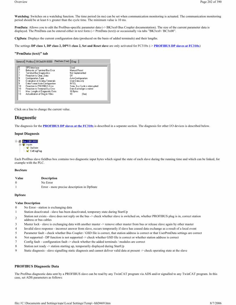
Watchdog: Switches on a watchdog function. The time period (in ms) can be set when communication monitoring is actuated. The communication monitoring period should be at least 6 x greater than the cycle time. The minimum value is 10 ms.
PrmData: Allows you to edit the Profibus-specific parameter data (-> BK3xx0 Bus Coupler documentation). The size of the current parameter data is displayed. The PrmData can be entered either in text form (-> PrmData (text)) or occasionally via tabs ”BK3xx0 / BC3x00”.
CfgData: Displays the current configuration data (produced on the basis of added terminals) and their lengths.
The settings DP class 1, DP class 2, DPV1 class 2, Set and Reset slave are only activated for FC310x (-> PROFIBUS DP slaves at FC310x)
”PrmData (text)” tab
Click on a line to change the current value.
Diagnostic The diagnosis for the PROFIBUS DP slaves at the FC310x is described in a separate section. The diagnosis for other I/O devices is described below.
Input Diagnosis
Each Profibus slave fieldbus box contains two diagnostic input bytes which signal the state of each slave during the running time and which can be linked, for example with the PLC.
BoxState
DpState
PROFIBUS Diagnostic Data
The Profibus diagnostic data sent by a PROFIBUS slave can be read by any TwinCAT program via ADS and/or signalled to any TwinCAT program. In this case, set ADS parameters as follows:
Value Description0 No Error1 Error - more precise description in DpState
Value Description0 No Error - station is exchanging data1 Station deactivated - slave has been deactivated, temporary state during StartUp
2 Station not exists - slave does not reply on the bus -> check whether slave is switched on, whether PROFIBUS plug is in, correct station address or bus cables
3 Master lock - slave is exchanging data with another master -> remove other master from bus or release slave again by other master4 Invalid slave response - incorrect answer from slave, occurs temporarily if slave has ceased data exchange as a result of a local event5 Parameter fault - check whether Bus Coupler / GSD file is correct, that station address is correct or that UserPrmData settings are correct6 Not supported - DP function is not supported -> check whether GSD file is correct or whether station address is correct7 Config fault – configuration fault -> check whether the added terminals / modules are correct8 Station not ready -> station starting up, temporarily displayed during StartUp9 Static diagnosis - slave signalling static diagnosis and cannot deliver valid data at present -> check operating state at the slave
Page 202 of 390Overview
8/7/2006file://C:\Documents and Settings\tope\Local Settings\Temp\~hhD469.htm

Net-ID: PC Net ID.
Port: 300
IndexGroup: 0x5000 + Device-ID
IndexOffset: Hi-Word: Station Address, Lo Word: 0x100
Length: 6 - 244
The diagnostic data are structured as described in the DP standard.
Modular Profibus Devices Modular Profibus devices allow you to define the variables for a device by selecting one or more modules. This involves defining modules with their inputs and outputs in the GSD file of the corresponding device. The following dialogue appears when adding/inserting a module:
Variables
The variables of a module can assume one of six types:
1. Byte (8 bit) 2. Word (16 bit) 3. Byte field (n * 8 bit) 4. Word field (n * 16 bit) 5. Byte string (n * 8 bit, consistent) 6. Word string (n * 16 bit, consistent)
The module can have in and/or outputs - and different types.
Overview Below listed node types with Interbus interface are currently supported by TwinCAT:
(Hint: Via the also listed "Generic Interbus Box", all Interbus slaves with given Ident.-Code and Ident.-Length are additionally supported, of course!)
TwinCAT System Manager: Reference
TwinCAT System Manager: Reference
Page 203 of 390Overview
8/7/2006file://C:\Documents and Settings\tope\Local Settings\Temp\~hhD469.htm

InterBus-S Device InterBus-S boxes which are not recognised by the TwinCAT System Manager can be inserted by inputting InterBus-S-specific length and identity codes. The length and identity codes for each device are given in the corresponding manual and are frequently marked on the device itself.
When adding an InterBus-S box you will see the following dialogue:
Context menu
Append Box... <Insert>
Adds, in the case of InterBus-S Bus Terminals, a box to the local or remote bus.
Actuate the ”List...” button to display a list of current InterBus-S boxes, whose length and identity codes are known.
When adding another InterBus-S box you will see the following dialogue:
Interbus - Node Type ("Box") Description Restrictions / CommentBK4000 Standard Bus Coupler BK4010 Economy Bus Coupler BC4020 "Economy plus" Bus Coupler BC4000 Bus Terminal Controller with Interbus Slave-interface IPxxxx-B400 Fieldbus Compact Box: Interbus input/output
module, protection class IP67
ILxxxx-B400 Fieldbus Coupler Box: Expandable input/output module, protection class IP67
ILxxxx-C400 Fieldbus PLC Box: Interbus Coupler Box with integrated PLC, protection class IP67
(not yet available)
Generic Interbus Box Generic Interbus device. Specify the Ident.-Code and Ident.-Length or select pre-defined box.
TwinCAT System Manager: Reference
Page 204 of 390Overview
8/7/2006file://C:\Documents and Settings\tope\Local Settings\Temp\~hhD469.htm

Insert Box Before...
Adds another box above the marked box.
Delete Box... <Del>
Deletes the marked box and its sub-elements from the I/O configuration.
Import Box Before...
Adds another box above the marked box. The description of the new box and its sub-elements are read from a file with the suffix "*.tce". This file is created with the following menu option.
Export Box...
Exports the information from the selected box and the information about its sub-elements into a file with the suffix "*.tce".
"InterBus-S" tab
Identity Code: Displays the identity code for the Bus Coupler. It is calculated dynamically - according to the connected terminals.
Length Code: Displays the length code for the Bus Coupler. It is calculated dynamically - according to the connected terminals.
Installation depth: Displays the installation depth of the Bus Coupler. It is calculated dynamically - according to the hierarchical structure of the InterBus-S.
The following settings are only possible in the case of the Phoenix IBS ISA ST-I/T.
Group: Allows the assignment of the device to a group (see Interbus user manual).
Alternative: Allows the assignment of the device to an alternative (see Interbus user manual).
Data consistency: Allows you to increase the data consistency for this device
StartUp: Allows the execution of a Control_Active_Configuration command at the system StartUp for this device.
� Default: There is no command being executed for this device � Segment Off: A Segment_Off is being executed � Segment On: A Segment_On is being executed
"CAC/CDF" tab
Page 205 of 390Overview
8/7/2006file://C:\Documents and Settings\tope\Local Settings\Temp\~hhD469.htm

Allows the execution of some firmware services of the Phoenix IBS ISA ST-I/T when an ADS port is active for the master card. See Interbus user manual. Note that a Control_Active_Configuration command will affect subsidiary devices!
Input Diagnosis
Each InterBus-S fieldbus box contains one diagnostic input byte which signals the status of the current slave during the running time and can be linked, for example with the PLC.
PCP Communication
Some InterBus-S devices can carry out non-cyclical communication with the master card as well as cyclical process data exchange (not CIF40-IBSM). The communication in the case of InterBus-S is called PCP communication (Peripherals Communication Protocol).
The devices are recognised by their identity code and have an additional tab.
”Enable” PCP communication assigns an AMS port to the device, via which the PCP communication is processed via ADS.
On the InterBus side, the communication connection between this device and the master card receives a communication number (CR = Communication Reference). A password and an access group number can also be specified (see description of PCP communication).
PCP services
The following services are currently supported:
1. Read (0x0081) 2. Write (0x0082) 3. Start (0x0083) 4. Stop (0x0084) 5. Resume (0x0089) 6. Reset (0x008A)
The required service is specified by entering the service code (mentioned above) in the ADS IndexGroup HIWORD (see ADS documentation).
You can simplify the process by using the code 0 for the read service in the case of an AdaReadReq and the write service in the case of an AdsWriteReq.
Index: The required PCP Index is entered in the LOWORD of the IndexGroup.
Sub-index: The required PCP sub-index is entered in the IndexOffset.
Overview Below listed node types with CANopen slave interface are currently supported by TwinCAT:
Variable Value Description
BoxState
0x01 Rec: Reconfiguration0x02 Mod: Module error0x04 W2Err: Error at the W2 interface0x08 W1Err: Error at the W1 interface0x10 W2: W2 interface inactive0x20 W1: W1 interface inactive
TwinCAT System Manager: Reference
Page 206 of 390Overview
8/7/2006file://C:\Documents and Settings\tope\Local Settings\Temp\~hhD469.htm

(Hint: Via the also listed generic "CANopen Node", all CAN[open] compliant slaves are supported, of course!)
CANopen Device CANopen devices which are not recognised by the TwinCAT System Manager can be incorporated into the network by selecting the box ”CANopen Node”. The CAN(open) messages (PDOs) can be configured directly for these devices. This will guarantee the optimum flexibility of this general CANopen interface.
When using the FC510x, this box also enables you to receive and send any CAN identifier - this enables communication with any CAN node. The only condition is the support of at least one of the Baud Rates supported by the FC510x.
"CAN Node" tab
Node ID: Enter the general CANopen device node address here. If you select the ”Auto Adapt PDO COB Ids” box, the default identifier for the process data object can also be carried out after changing the node ID.
Profile No.: After CANopen, the parameter 0x1000 "Device Type" contains the number of the supported device profile in both the lowest value bytes. These are entered here and compared at the system StartUp with the device parameters present. If no device profile is supported, the parameter will contain the value 0.
Add Info: The additional info is located in both the highest value bytes of the object directory entry 0x1000 (device type).
FC510x: Comparison of the set/actual configuration takes place only if the profile no. or add info (i.e. object directory entry 0x1000) are configured to a value other than zero. If the expected data at the system start do not comply with the values present, the StartUp of this node will be interrupted and a corresponding error message will appear in the Diag Tab.
CIFx0-CAN: The values are continuously compared (even if ”0” is entered in both). If values do not comply, the node StartUp is interrupted.
Guard Time: The guard time determines the interval in which the node is monitored (node guarding). 0 signifies no monitoring.
Life time factor: Guard time x lifetime factor determines the watchdog length for the mutual monitoring of card and CANopen nodes. 0 indicates that the
CANopen - Node Type ("Box") Description Restrictions / CommentBK5100 Bus Coupler BK5110 Economy Bus Coupler BK5120 Bus Coupler, successor of BK5100 LC5100 Low-cost Bus Coupler
IPxxxx-B510 Fieldbus Compact Box: CANopen Ein-/Ausgabebaugruppe in Schutzart IP67
ILxxxx-B510 Fieldbus Coupler Box: Expandable CANopen in/output module, protection class IP67
AX2000-B510 Beckhoff AX2000 drive with integrated CANopen Interface (X6)
CANopen Slave FC510x Beckhoff FC5101 resp. FC5102 as CANopen slave node
CANopen Node Generic CANopen device or generic CAN device (access via CAN level 2)
TwinCAT System Manager: Reference
Page 207 of 390Overview
8/7/2006file://C:\Documents and Settings\tope\Local Settings\Temp\~hhD469.htm

CANopen node is not monitoring the card. At 0 the card takes the guard time directly as the watchdog length.
FC510x: This card also supports the heartbeat protocol and firstly attempts to start this form of node monitoring on the CANopen node (write access to objects 0x1016 and 0x1017 in the object directory). If this attempt fails, guarding is activated. The guard time as producer heartbeat time and (guard time x lifetime factor) as consumer heartbeat time are entered. The card then transmits its heartbeat telegram with the smallest configured guard time (the guard times can be set individually for each node).
Emcy COB Id. and Guard COB Id. are the identifiers for emergency messages and/or guarding protocol and are based on the node address.
Automatic PDO... Specifies whether TwinCAT should download the PDO communications parameters to the node at the system start.
FC510x: If the download of the PDO parameters fails, the card attempts to read these parameters and compares them with the configured values. In this way, it supports only those nodes which, e.g. have implemented the default identifiers as read-only values.
CIFx0-CAN: The PDO parameters are transferred to the CANopen node, but allowance is made if the node does not support these inputs - requires only the conformation of the SDO access (an SDO abort response is sufficient).
Vendor ID, Product Code, Serial No., Revision No. (FC510x only): If values other than zero are entered here, these identity object inputs (0x1018 in the object directory) are read off at the system StartUp and compared with the configured values. The corresponding node will be started only if the values coincide. It is also possible to compare one part of the value (e.g. vendor ID and product code) - in this case set the not desired parameters to zero.
Node Error Response (FC510x only):
Stop Node: After a recognised node error, the node is set to ”Stopped” mode (NMT command "Stop Remote Node"). The node (according to each device profile) can then be switched to a safe mode via the network status machine - SDO addressing is not possible in this mode.
No Response: No NMT stop remote node command after node error
Node Restart (FC510x only):
Automatic Restart: After a recognised node error the card automatically attempts to restart the node. The StartUp attempt is initiated by a node reset command.
Manual Restart: After a node error, this node remains in error mode and is not restarted automatically. You can actuate a restart via "I/O-Reset".
Network Response (FC310x only):
No Response: The failure of a node has no effect on the other bus devices
All Nodes Stop: After the failure of a node, all other previously started nodes are stopped (NMT stop remote node command). You then need to restart the system.
General CAN Node (FC510x only): If you have selected this checkbox, the entire CANopen network management for this device is deactivated. It is not started, monitored etc. The PDO inputs are detected as pure CAN (2-layer) telegrams and enable the controller to operate in event driven mode.
Warning: As the CANopen terminology is retained, even in the case of the general CAN nodes, you need to take into account the fact that RxPDOs are the telegrams sent by the Fc510x and TxPDOs are the received telegrams.
This option allows any CAN node to be connected to the TwinCAT, if the Baud Rate and the bit timing parameters comply. The respective protocol can then be simulated within the PLC program. It is also possible to run CANopen devices and general CAN nodes within the same network - if there are no identifier overlaps (the system structure is such that you cannot use an identifier twice).
CANopen PDOs
Process Data Objects (PDOs) are CAN telegrams which transport process data without a protocol overhead. RxPDOs are received by node, TxPDOs are sent by the node. This description is contained in the System Manager from the perspective of the configured node, i.e. RxPDOs are sent by the TwinCAT, TxPDOs are received by the TwinCAT.
”PDO” tab
Page 208 of 390Overview
8/7/2006file://C:\Documents and Settings\tope\Local Settings\Temp\~hhD469.htm

COB Id: The CAN identifier of this PDO. For every two send and receive PDOs per node, CANopen provides Default Identifiers. These can then be changed.
Trans.Type: The Transmission Type determines the send behaviour of the PDO. 255 corresponds to the event driven send.
Inhibit time: Send Delay between two identical PDOs. Is entered in multiples of 0.1 ms.
Length: The length of the PDO is based on the mapped variables and cannot therefore be edit here.
Event Time (FC510x only): Enter the value for the Event Timer in ms. For send PDOs (here: RxPDOs, see above) the StartUp of this timer triggers an additional PDO send, for receive PDOs (here: TxPDOs) the arrival of a PDO within the pre-set value is monitored and the box state of the node is changed as appropriate. If 0, the parameter is not transferred to the node.
TwinCAT creates corresponding inputs in the node object directory on the basis of the parameters entered here. These are transferred via SDO at the system start. You can view the inputs at the SDO tab. If this behaviour is not required, you can deactivate "Auto Download of PDO Parameters" by selecting the checkbox at the CAN node tab.
Tree Representation:
TwinCAT firstly provides two send and receive PDOs, with Default Identifiers, for a general CANopen node. Superfluous PDOs can be selected and removed.
TxPDOs are sent by the CANopen node and generally contain inputs. RxPDOs are received by the node, i.e., sent by TwinCAT.
Add variables to the PDOs by right clicking on ”Inputs” and/or ”Outputs” and selecting the corresponding variable(s). If several variables of the same type are inserted with a single action, the offset within the PDO will be created automatically. If variables are inserted one after another, you need to set the corresponding offset (start address within the CAN telegram) for each variable.
Please note that TwinCAT assigns the PDOs to the object dictionary entries in the node using the sequence in which the system manager displays the PDOs. For instance the PDO communication parameter of the third listed TxPDO are always written to index 0x1802 - independent of the name of the PDO in the system manager. So if only PDO1 and PDO3 are to be used, PDO2 has to be entered as well - in this case without variables assigned. PDOs without variables are not sent and are not expected by the card.
Context menu:
The menu alongside is obtained by right clicking on the general CANopen node. Here you can insert further Tx PDOs and/or Rx PDOs.
”SDOs” tab
Page 209 of 390Overview
8/7/2006file://C:\Documents and Settings\tope\Local Settings\Temp\~hhD469.htm
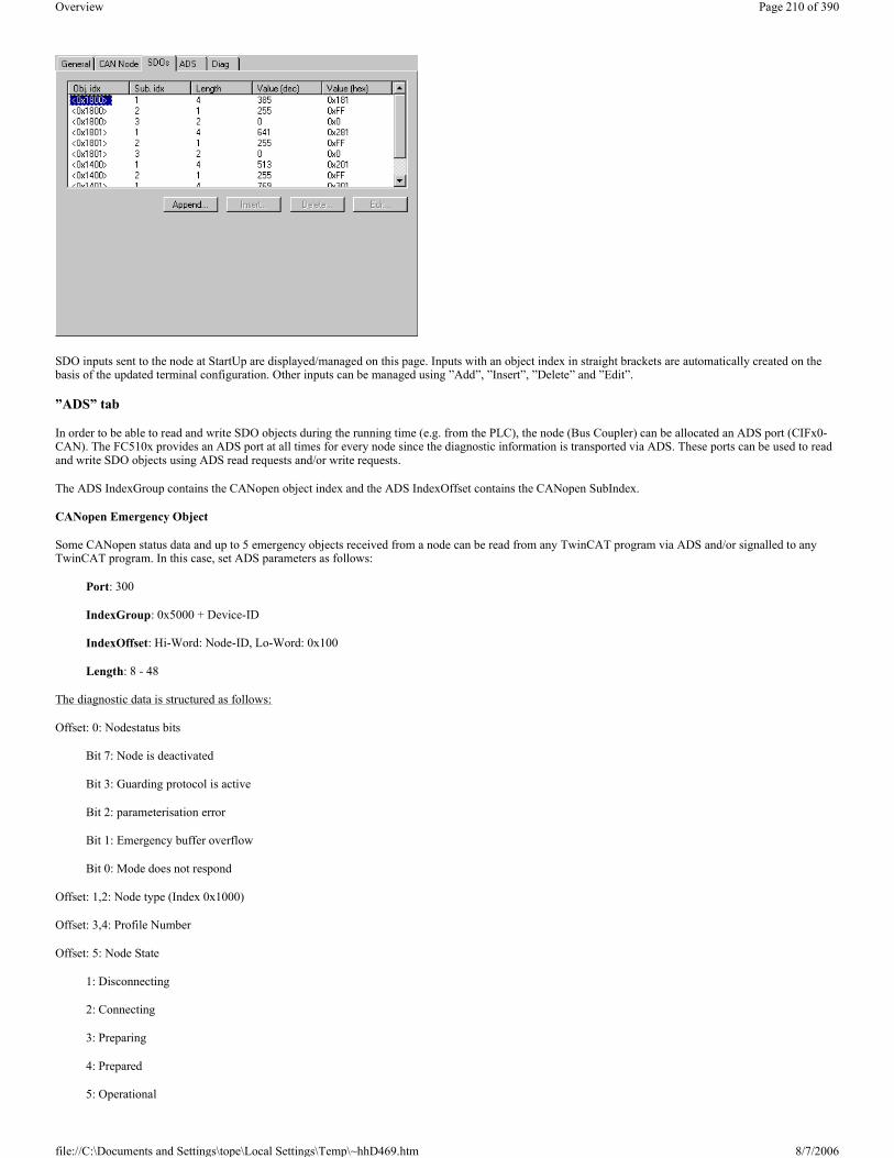
SDO inputs sent to the node at StartUp are displayed/managed on this page. Inputs with an object index in straight brackets are automatically created on the basis of the updated terminal configuration. Other inputs can be managed using ”Add”, ”Insert”, ”Delete” and ”Edit”.
”ADS” tab
In order to be able to read and write SDO objects during the running time (e.g. from the PLC), the node (Bus Coupler) can be allocated an ADS port (CIFx0-CAN). The FC510x provides an ADS port at all times for every node since the diagnostic information is transported via ADS. These ports can be used to read and write SDO objects using ADS read requests and/or write requests.
The ADS IndexGroup contains the CANopen object index and the ADS IndexOffset contains the CANopen SubIndex.
CANopen Emergency Object
Some CANopen status data and up to 5 emergency objects received from a node can be read from any TwinCAT program via ADS and/or signalled to any TwinCAT program. In this case, set ADS parameters as follows:
Port: 300
IndexGroup: 0x5000 + Device-ID
IndexOffset: Hi-Word: Node-ID, Lo-Word: 0x100
Length: 8 - 48
The diagnostic data is structured as follows:
Offset: 0: Nodestatus bits
Bit 7: Node is deactivated
Bit 3: Guarding protocol is active
Bit 2: parameterisation error
Bit 1: Emergency buffer overflow
Bit 0: Mode does not respond
Offset: 1,2: Node type (Index 0x1000)
Offset: 3,4: Profile Number
Offset: 5: Node State
1: Disconnecting
2: Connecting
3: Preparing
4: Prepared
5: Operational
Page 210 of 390Overview
8/7/2006file://C:\Documents and Settings\tope\Local Settings\Temp\~hhD469.htm

127: Pre-Operational
Offset: 6: Current Error
30: Guarding malfunction
31: Node has changed status
32: Sequence error in guarding protocol
33: No answer from remote frame PDO
34: No answer during a node configuration
35: Incompatible node profile number
36: Incompatible node device type number
37: Unknown SDO response received
38: SDO syntax error
39: Node in STOP mode
Offset: 7: Number of Emergency Messages
Offset: 8-47: Emergency buffer (-> node description)
The data contain the current status. The emergency buffer contains the last emergency messages received. The node status bits are collated in the box state diagnostic input.
CAN Box Reset
CAN box Reset takes place in 8 steps.
1. Step:
At first, you have to add the box. Open the dialog box under the device (here FC510x, CANopen Master, PCI).
2. Step:
Choose 'CANopenNode' in the diaolg 'Insert device'.
3. Step:
The box has 2 inputs and outputs. You have to delete TxPDO1, TxPDO2 and RxPDO1.
TwinCAT System Manager: Reference
Page 211 of 390Overview
8/7/2006file://C:\Documents and Settings\tope\Local Settings\Temp\~hhD469.htm

4. Step:
The apporpriately tab must have the following settings:
5. Step:
At the output RxPDO1 tab, the COB ID must be set to zero.
6. Step:
When you open the dialog box under RxPDO 1 'outputs' , you can insert further variables.
7. Step:
The appropriately tab must have the following settings:
Page 212 of 390Overview
8/7/2006file://C:\Documents and Settings\tope\Local Settings\Temp\~hhD469.htm
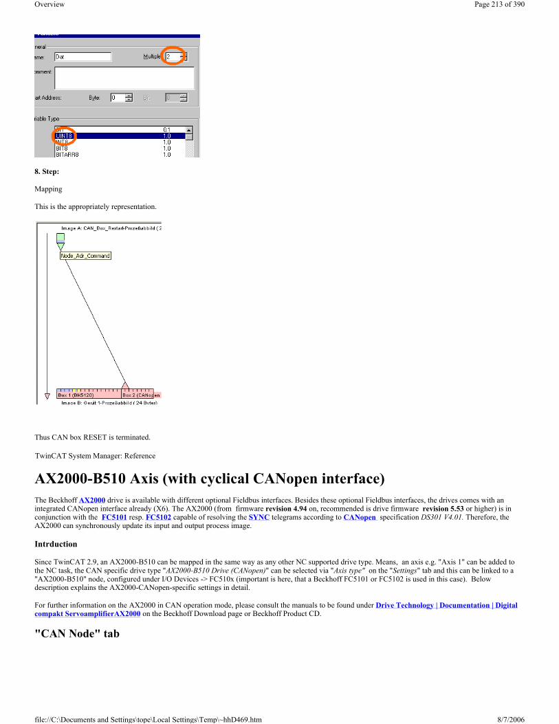
8. Step:
Mapping
This is the appropriately representation.
Thus CAN box RESET is terminated.
AX2000-B510 Axis (with cyclical CANopen interface) The Beckhoff AX2000 drive is available with different optional Fieldbus interfaces. Besides these optional Fieldbus interfaces, the drives comes with an integrated CANopen interface already (X6). The AX2000 (from firmware revision 4.94 on, recommended is drive firmware revision 5.53 or higher) is in conjunction with the FC5101 resp. FC5102 capable of resolving the SYNC telegrams according to CANopen specification DS301 V4.01. Therefore, the AX2000 can synchronously update its input and output process image.
Intrduction
Since TwinCAT 2.9, an AX2000-B510 can be mapped in the same way as any other NC supported drive type. Means, an axis e.g. "Axis 1" can be added to the NC task, the CAN specific drive type "AX2000-B510 Drive (CANopen)" can be selected via "Axis type" on the "Settings" tab and this can be linked to a "AX2000-B510" node, configured under I/O Devices -> FC510x (important is here, that a Beckhoff FC5101 or FC5102 is used in this case). Below description explains the AX2000-CANopen-specific settings in detail.
For further information on the AX2000 in CAN operation mode, please consult the manuals to be found under Drive Technology | Documentation | Digital compakt ServoamplifierAX2000 on the Beckhoff Download page or Beckhoff Product CD.
"CAN Node" tab
TwinCAT System Manager: Reference
Page 213 of 390Overview
8/7/2006file://C:\Documents and Settings\tope\Local Settings\Temp\~hhD469.htm

Node Id: The address of the CANopen node (in this case the CAN address of the AX2000 drive) has to be assigned here. The drive internal setting of this address can be set via the AX2000 configuration software SR600 or through the ASCII - communication mode. The address given in this dialog has to match the internal set drive address.
Profile No.: + Add. Information : This object (0x1000) describes device type (Servo drive) and device functionality (DS402 drive profile).
It is the combination of the following:
Guard Time (ms): Watchdog-time in milliseconds.
Life Time Factor: Specifies the handling of the "Guard Time". E.g. a here entered "0" deactivates the watchdog. Default value is "3".
Rest of the parameters, see: CANopen device
Adjustments of Address and Baudrate with Drive Configuration Software The relevant settings for the CAN bus (Node Id, Baudrate,..) can be set via the basic settings of the SR600 software. By default address 1 and baudrate 500kb is set. After changing these values, a "Save to EEProm" with a following coldstart is necessary (SAVE command with following COLDSTART).
Description Value BitNumber of the device profile: Drive profile 402 (dec.) 0x192 (hex.) 0 - 15 Type: Servo drive 2 (dec.) 0x2 (hex.) 16 - 23 Mode bits: (Not shown in the dialog. Bits are going to be masked if necessary into the Hi-Byte of the Hi-WORD)
Vendor-specific 0 24-31
Page 214 of 390Overview
8/7/2006file://C:\Documents and Settings\tope\Local Settings\Temp\~hhD469.htm

Adjustments of Address and Baudrate via serial COM port (Hyperterminal) Start MS Windows Hyperterminal (Start | Run | hypertrm.exe). Connection settings are: '9600 Baud, 8 Bit, 1 Stop Bit, no Parity, no Handshake'. Clicke into the window and press Enter.
If the serial cable is connected correctly (X6 ----- RS232), the Cursor " -->" should appear in the window.
Hint: If you solder the jumper wire between pin 7 and 8 on both ends, the cable will be symmetric and it's not important therefore which end is going to be connected to the drive/PC afterwards.
To read the actual parameter, type the ASCII command without parameter (e. g. ADDR). The next line shows the parameter value in this case.
To write a parameter value (e.g. the drive address), type command and value in one line (e.g. ADDR 1).
"AX2000-B510" tab On this tab, the operating mode for the AX2000 has to be selected. Two different modes are available:
Position Control: As default setting, "Position Control" is selected. In this operating mode, TwinCAT NC prescribes cyclically a new position. The positioning profile is generated by TwinCAT NC in this case. With the cycle time of the SAF-Task (e.g. 10ms), position setpoint values are transmitted are going to be transmitted via the CANopen interface. On the AX2000, 3 cascaded control loops are implemented. These are the control loops for Current (65µs), Speed (250µs) and Position (synchronized with the cycle time of the triggering SAF-Task). The position control loop is completely handled by the AX2000. The position feedback is established through the cyclical interface.
Page 215 of 390Overview
8/7/2006file://C:\Documents and Settings\tope\Local Settings\Temp\~hhD469.htm

Velocity Control: Alternatively, "Velocity Control" can be activated. In this mode, the velocity is the actuating unit for the AX2000. The number of internal control loops reduces to 2 in this case, namely the Current (65µs) and Speed controller (250µs). The observance of the setpoint position is controlled by TwinCAT NC. The feeback value of the position is transmitted via the cyclical interface. Since the velocity control mode needs quicker update times at the TwinCAT NC, the cycle time of the SAF-Task has to be set to 2ms in this case.
Save: After changing the cycle time of the triggering task (usually the NC SAF - Task) or after changing the operation mode (OPMODE), the "SAVE" button should be pressed to execute the command which saves the parameters to the drive EEPROM.
Coldstart: If the parameters are saved (approx. 3s after "SAVE" ), a "COLDSTART" of the amplifier (drive) is necessary.
Hint:
The commands SAVE and COLDSTART can even be executed at enabled amplifiers (drives).
"SDOs" Tab This tab allows the configuration of the startup parameters for the selected CAN node. This is done through the Service Data Objects (SDO's). Those entries which are listed with object indexes in brackets, were configured automatically according to the Bus Terminals resp. pre-configured PDO's attached to this node type. Additional entries are to be configured with "Append..", "Insert...", "Delete..." and "Edit...".
The SDO's are used at first hand for the parameterization of the CAN nodes and PDOs. With the first two entries the properties of the TxPDO1 are defined:
Analogous, the RxPDO is to be configured.
Object Index Sub Idx Length Value Description0x1800 1 4 0x18B Cob ID (address for the transmit message of node 11). This is a "Default Identifier"0x1800 2 1 1 Transmission Type
Page 216 of 390Overview
8/7/2006file://C:\Documents and Settings\tope\Local Settings\Temp\~hhD469.htm

Self-defined SDO's
Controller configuration
PDO Mapping
The AX2000 uses 4 Send- (TxPDO1..4) and 4 Receive PDO's (RxPDO1..4). The content of the messages (PDOs) depends on the operation mode and mapping. Currently, 7 pre-defined RxPDO's and 6 TxPDOs exist. Besides that, the possibility of self-combined messages exists.
Hint: Not every object can be assigned to a free-defined PDO.
At "Position Control", the RxPDO as well as the TxPDO was self-configured. At "Velocity Control", the TxPDO has been selected from the pool of the pre-defined PDO's. The RxPDO has been self-configured, though.
Example:
"ADS" Tab Via the shown AmsNetID + Port number (address) it is possible to read and write parameters from/to the AX2000 (e.g. from PLC).
Example: To read the divice type, the object information Index: 0x1000, SI: 0x0 is used.
Object Index Sub Idx Length Value Description
0x6040 2 2 0Sets Drive ControlWord to zero. The controller is in the state "Switch On Disable" in that case. The AX2000 is in ready-for-operation mode, parameters can be transmitted, DC-voltage can be switched on. Move commands cannot yet be executed.
0x3683 1 1 3 ASCII command: SyncSRC
0x363b 1 1 3 Synchronization mode, especially adapted to the CAN interface implementation. ASCII command: FPGA
0x35d5 1 1 40 Value = Task Cycl / Speed Controller Cycl 40 = 1000µs / 250µs. ASCII command: PTBASE
0x6060 0 2 0xFA With this entry, the OPMODE of the drive is defined: 0xFA = Position Control 0xFE = Velocity Control
0x3672 1 1 2 Manipulating of the CANopen state-machine with Enable/Disable.
Object Index Sub Idx Length Value Description0x2600 0 1 0x25 Selection of a self-defined RxPDO (37..40)0x1600 0 0 0 Clear mapping
0x1600 1 4 0x60400010 The first element of the message is the ControlWord (0x6040). Sub element SI: (0x00) Length: (0x10), 16 Bit
0x1600 2 4 0x20220420 The first element of the message is the SetpointPosition (0x2022). Sub element SI: (0x04) Length: (0x20), 32 Bit
Page 217 of 390Overview
8/7/2006file://C:\Documents and Settings\tope\Local Settings\Temp\~hhD469.htm

"DIAG" Tag Under this tab, detailed error messages are displayed. With a wrong configured Additionional Information for example, the CANopen Master e.g. detects the difference between the configured value and the one contained in the drive. If everything is ok and the drivy is ready for operation, it shows"".
AX2000-B510 Diagnosis Inputs
The diagnosis Inputs of an AX2000-B510 don't differ from the diagnosis inputs of other TwinCAT CANopen nodes (see also: "FC510x: Box-Diagnosis").
Process Image The TxPDO's and RxPDO's are to be seen from the slave point of view. The input process image (TxPDO) contains a "State" and "ActualPos" process variable. The output process image (RxPDO) contains a "Ctrl" and a "NominalPos" variable.
"State": Object information Index: 0x6041, SI: 0x0, Len: 2
"ActualPos": Current drive position. Object information Index: 0x2070, SI: 0x3, Len: 4
Bit Name Bit Name 0 Ready to switch on 8 Manufacturer specific (reserved)1 Switched on 9 Remote (not supported)2 Operation enable 10 Target reached3 Fault (i.V.) 11 Internal limit active (not supported)4 Disable voltage 12 Operation mode specific (reserved)5 Quick stop 13 Operation mode specific (reserved)6 Switch on disabled 14 Manufacturer specific (reserved)7 Warning 15 Manufacturer specific (reserved)
Page 218 of 390Overview
8/7/2006file://C:\Documents and Settings\tope\Local Settings\Temp\~hhD469.htm

Via this index, the incremental encoder value (drive emulated) of the current position can be read. One revolution has an incremental value of a 20 bit resolution. That means: 1 revolution 2 ²º increments = 1048576 increments. The adjustedresolution per revolution can be checked with the ASCII command "PRBASE". Default value: 20 bit/rev.
"Ctrl": Object information Index: 0x6040, SI: 0x0, Len: 2
"NominalPos": Setpoint position. Object information Index: 0x2022, SI: 0x4, Len: 4
Via this parameter, the incremental value of the setpoint position is prescribed.
"NominalVelo": Setpoint velocity. Object information Index: 0x2060, SI: 0x0, Len: 4
Via this parameter, the scaled setpoint velocity is prescribed.
Overview Below listed node types with DeviceNet slave interface are currently supported by TwinCAT:
(Hint: Via the also listed generic "DeviceNet Node", all DeviceNet compliant slaves with valid EDS file are additionally supported, of course!)
DeviceNet Device Select DeviceNet node to integrate general DeviceNet devices. You then need to enter the connection parameters for these devices.
"DeviceNet Node" tab
Bit Name Bit Name 0 Switch on 8 Halt (intermediate stop command)1 Disable Voltage 9 (reserved)2 Quick Stop 10 (reserved)3 Enable Operation 11 Acknowledge lag-distance and watchdog 4 Operation mode-specific 12 Reset position5 Operation mode-specific 13 Manufacturer specific (reserved)6 Operation mode-specific 14 Manufacturer specific (reserved)7 Reset Fault (only active after error messages) 15 Manufacturer specific (reserved)
TwinCAT System Manager: Reference
DeviceNet - NodeType ("Box") Description Restrictions / CommentBK5200 Bus CouplerBK5210 Economy Bus Coupler BK5220 "Economy plus" Bus Coupler LC5200 Low-cost Bus CouplerIPxxxx-B520 Fieldbus Compact Box: DeviceNet in/output modules,
protection class IP67
ILxxxx-B520 Fieldbus Coupler Box: Expandable DeviceNet in/output modules, protection class IP67
FC5201 Slave External FC5201 resp. FC5202 as slave node at the DeviceNet bus
DeviceNet Node Generic DeviceNet node (EDS file required)
TwinCAT System Manager: Reference
Page 219 of 390Overview
8/7/2006file://C:\Documents and Settings\tope\Local Settings\Temp\~hhD469.htm

MAC Id: Sets the node ID of the DeviceNet participant (between 0 and 63). This value must comply with the value set at the node.
Cycle Time: Sets the cycle time for the I0 connection. This value is added to the Expected Packet Rate (EPR) attributes of the DeviceNet slave and acts as a timeout monitor for IO connections.
Electronic Key: Serves to check the devices within the network at the system StartUp. The electronic key is read from the devices at every system StartUp and compared with the saved configuration.
Polled: Produced/Consumed: Activation of the ”Polling” operating mode, cyclical writing and reading of IO data
Bit-Strobed: Produced/Consumed: Activation of the ”Bit Strobe” Operating Mode. With a broadcast message all nodes are requested to send their bit strobe message (up to 7 bytes input or status data).
Change of State / Cyclic: Produced/Consumed: Activation of "Change of State" operating mode, event controlled sending of IO data or ”Cyclic”, cyclical sending of IO data.
- Change of State / Cyclic: Selecting the Corresponding Operating Mode
- Heartbeat Rate / Scan Rate: In the "Change of State" mode the heartbeat rate gives the cycle time of the cyclical send of the lower-level (i.e. in addition to the event driven) IO data. In the ”Cyclic” operating mode the scan rate gives the cycle time of the IO data send.
Inhibit time: Delay period in the ”Change of State” operating mode inserts this pre-set delay period after a change of state before the IO data send.
Acknowledge Timeout: Time before the re-send in the event of faulty acknowledgement of a change of state / cyclical message.
Acknowledge Retry Limit: Maximum number of re-sends until IO connection goes into error mode.
K-Bus Update: Calculates the anticipated duration of a complete update of the terminal bus (according to the number of connected terminals).
Input Diagnosis:
Each DeviceNet fieldbus node contains one diagnostic input byte which signals the status of the current slave during the running time and can be linked, for example with the PLC.
BoxState
DataExchange
Error Code Description Troubleshooting0x02 Station not exists, device is not responding Inspect the device, verify connections, check cabling
0x05 Parameter fault Check explicite access to devices attributes, check object class, instance and attribute id
0x07 Configuration fault Check configuration settings of device0x09 Device is deactivated Check master and device configuration
Error Code Description Troubleshooting0x00 No data exchange between node and master Inspect the field device, verify connections, check cabling0x01 Data Exchange is active
Page 220 of 390Overview
8/7/2006file://C:\Documents and Settings\tope\Local Settings\Temp\~hhD469.htm

”Attributes” tab
DeviceNet attributes/parameters sent to the node at StartUp are displayed/managed on this page. Other inputs can be managed using ”New”, ”Delete” and ”Edit”.
”ADS” tab
In order to be able to read and write attributes during the running time (e.g. from the PLC), the node (Bus Coupler) can be allocated an ADS port. These can be used to read / write attributes via ADS read requests / ADS write requests.
The ADS IndexGroup contains the ClassId and the ADS IndexOffset contains InstanceId and AttributeId (InstanceId * 256 + AttributeId).
Diagnostic data
The DeviceNet status data from a node can be read by any TwinCAT program via ADS and/or signalled to any TwinCAT program.
”Parameter” tab
Page 221 of 390Overview
8/7/2006file://C:\Documents and Settings\tope\Local Settings\Temp\~hhD469.htm

The parameters are read from the EDS when creating the box. If the system has not started up yet, the EDS default value is always displayed under the value input.
Overview The following devices with SERCOS interface are currently supported by TwinCAT:
SERCOS Axis ”SERCOS Drive” tab
Address: SERCOS axis address which must be the same as the one on the drive amplifier.
Operating mode: Sets the SERCOS operating mode for the axis. It supports the speed operating mode (velocity control) in which speed command values are sent to the drive and the position control mode.
TwinCAT System Manager: Reference
SERCOS - Node Types ("Box") Description Restrictions / Commente
SERCOS Axis Generic SERCOS axisThe SERCOS implementation in TwinCAT is generic, means drive type independent, as long as the drive is SERCOS standard compliant.
BK7500 Beckhoff Standard Bus CouplerBK7520 Beckhoff "Economy plus" Bus Coupler
TwinCAT System Manager: Reference
Operating mode Description
Velocity The drive receives digital velocity setpoints, which are generated by the TwinCAT NC controller on the PC.
Position 1The drive receives digital position setpoints cyclically generated by TwinCAT NC. The loop is closed by the drive. The motor resolver provides actual position values (Position 1, Resolver, S-0-0051).
Position 2 The drive receives digital position setpoints cyclically generated by TwinCAT NC. The loop is closed by the drive. An external encoder provides actual position values (Position 2, S-0-0053).
Position 1+2 The drive receives digital position setpoints cyclically generated by TwinCAT NC. The loop is closed by the drive. Actual position feedback is provided from external encoder and from Resolver.
Position 1 without Lag Drive-internal interpolation (drive is deployed without linkage to TwinCAT NC controller). The motor resolver provides actual position values (Position 1, Resolver, S-0-0051).
Page 222 of 390Overview
8/7/2006file://C:\Documents and Settings\tope\Local Settings\Temp\~hhD469.htm

NOTE:
In positioning operating mode ensure that, if using a loop axis in the weighting mode for position data (S-0-0076), the modulo function is switched on and the resulting modulo value (S-0-0103) is recognised by TwinCAT (see ”SERCOS” tab).
NOTE:
In speed operating mode ensure that the output scaling for the drive is set correctly in TwinCAT (see ”SERCOS” tab).
Telegram type: Defines the telegram structure to and from the drive. Default setting is "Configurable Telegram" (see table below).
NOTE :
The calculation described under FC750x at the "Timing Offline" Tab , is based on telegram type 2 to 4.
”Startup” tab
Position 2 without Lag Drive-internal interpolation (drive is deployed without linkage to TwinCAT NC controller). An external encoder provides actual position values (Position 2, S-0-0053).
Position 1+2 without Lag Drive-internal interpolation (drive is deployed without linkage to TwinCAT NC controller). Actual position feedback is provided from external encoder and from Resolver.
Telegram type Description
Telegram 1 (80 / -) The telegram to the drive contains only the torque command value (IDN 80, S-0-0080). No actual value returns from the drive at this telegram type.
Telegram 2 (36 / 40)Telegram to drive: Velocity command value (IDN 36, S-0-0036)
Telegram from drive: Velocity feedback value (IDN 40, S-0-0040)
Telegram 3 (36 / 51)Telegram to drive: Geschwindigkeits-Sollwert (IDN 36, S-0-0036)
Telegram from drive: Position feedback value 1, Resolver (IDN 51, S-0-0051) Telegram 3 ext. (36 / 53) Telegram to drive: Velocity command value (IDN 36, S-0-0036)
Telegram from drive: Position feedback value from external encoder (IDN 53)
Telegram 4 (47 / 51)Telegram to drive: Position command value (IDN 47, S-0-0047)
Telegram from drive: Position feedback value 1, Resolver (IDN 51, S-0-0051)
Telegram 4 ext. (47 / 53)Telegram to drive: Position command value (IDN 47, S-0-0047)
Telegram from drive: Position feedback value from external encoder (IDN 53)
Telegram 5 (47 36 / 51 40)Telegram to drive: Position and velocity command value
Telegram from drive: Position 1 and velocity feedback value
Telegram 5 ext. (47 36 / 53 40)Telegram to drive: Position feedback value from external encoder
Telegram from drive: Position 2 and velocity feedback value
Telegram 6 (36 / -) Telegram to drive contains only a velocity command value (IDN 36). No feedback value returns from drive
Configurable Telegram A user defined telegram structure with preferred command (nominal) and feedback (actual) values can be configured
Page 223 of 390Overview
8/7/2006file://C:\Documents and Settings\tope\Local Settings\Temp\~hhD469.htm

In this case SERCOS parameters can be set here which are sent to the drive at every TwinCAT StartUp via the NC service channel and which overwrite the existing drive values.
”Inputs” tab
Under "Inputs" (Actual Channel) all necessary and optional SERCOS parameters which come from the drive fin this case, are listed. Corresponding variables are automatically created below the axis in the tree view. These can be linked accordingly.
A position feedback value is required in all cases!
New...: After hitting this button, additional variables can be inserted into the cyclical receive telegram from the drive:
At Id. No., a supported IDN of the drive can be entered. Name is an edit field for a descriptive name for the IDN (suggested parameters from above shown list will fill this name field automatically). Additionally Accordingly, the appropriate data type for the wished IDN has to be selected from the list, shown on the right.
Page 224 of 390Overview
8/7/2006file://C:\Documents and Settings\tope\Local Settings\Temp\~hhD469.htm

”Outputs” tab
Variables, which have to be transmitted to the drive, are specified here as in the "Outputs". Depending upon the axis operating mode, the list on this tab must contain the "Velocity command value" or the "Position command" value. Further parameters can be added in the same way as under "Inputs" here.
”ADS” tab
The ADS port number, via which all ADS access to the internal drive parameters takes place, is entered here at the ADS tab.
”Online” tab
The NC service channel can be served via the online tab. TwinCAT must be started for this to take place and the SERCOS ring must be in at least phase 2.
Diagnosis: After a click on this button, updated diagnostic information (see also S-0-0095) will be displayed on the field right next to it.
Reset: After a click on this button, the axis and or amplifier reset will take place (see also S-0-0099).
The list below shows all SERCOS parameters with current values. This data is read from the drive online (incl. text and units) which means that scrolling through the list takes some time. If the drive supports this function you can choose between English and German output.
Change the parameters by double-clicking on the relevant ID no. to display a corresponding dialogue.
Context menu:
The list of SERCOS parameters may also be printed and exported (includes via drag and drop e.g. in Excel). Right click with the mouse to open a corresponding context menu:
Print List: Output of list on printer
Copy List: Copies the list into the Windows Clipboard
Copy selected IDN to Startup: If aktive, the selected IDN can be added to the Startup parameters here.
Export Complete List (CSV): After exporting the variable into a *.csv file (= comma separated values), the parameters could be further used in applications which support this file format (e.g. MS Excel).
Export Complete (PAR): Exports the parameters into the DriveTop compatible *.par file format.
Update List: Click on this button to reload the currently viewed values from the drive.
Page 225 of 390Overview
8/7/2006file://C:\Documents and Settings\tope\Local Settings\Temp\~hhD469.htm

Auto Update: Check this box to initiate a regular timed update (update rate approx. 2sec.).
Advanced: After a click on this button, the following dialog for the "Advanced Online Settings" comes up:
The upper left-hand list box allows you to place thresholds on the values displayed in the list on the "Online" tab. The system suggests a series of groups which define associated values in certain contexts. The last group on the list is a user-defined group. Any combination can be created in the right hand list in this case.
Backup / Restore: These two buttons are used to save the parameters defined by the drive (see also S-0-0192) to a (backup) file and subsequently reload those parameters into a replacement drive (restore). The format of the backup file corresponds to the parameter format (*.par), which is used by the DriveTop tool supplied by company Rexroth-Indramat. This enables you to carry out data exchange using this tool.
SERCOS IDs via ADS
SERCOS IDs can also be read and written (e.g. from the PLC) during runtime via ADS. In this case the axis must be allocated an ADS port via the ADS tab.This takes place as standard.
ADS read/write requests can be executed via this port. The IndexGroup corresponds to the required SERCOS IDN and the IndexOffset to the element of the SERCOS value:
Port No.: Number shown on "ADS" tab (see above)
IndexGroup: SERCOS ID, e.g.:
S-0-0123 = 123 (0x007B)
S-7-0101 = 101 + 0x7000 = 0x7065
P-0-0002 = 2 + 0x8000 = 0x8002
P-7-0004 = 4 + 0x8000 + 0x7000 = 0xF004
IndexOffset: Required element:
0 or 7 = value,
1 = Data Status,
2 = Name (read only),
3 = Attribute (see SERCOS specification),
4 = Unit,
5 = Minimum,
6 = Maximum
Page 226 of 390Overview
8/7/2006file://C:\Documents and Settings\tope\Local Settings\Temp\~hhD469.htm

Reset via ADS
The drive amplifier can be reset (e.g. after exceeded max. lag-distance) via ADS. To the SERCOS IDN S-0-0099 an ADSWrite command (or sequence) has to be sent. The command varies depending on the used SERCOS master card
- FC7501 resp. FC7502:
a drive reset can be achieved if to IndexGroup: 0x0063, IndexOffset: 8, a 3 is send ("ByRef", that means in this case: The address of a constant 3 has to be passed on to SrcAddr).
or at a
- SERCANS SCS-P Master card:
if the values 3, 0, 3 and 0 again, are sent "ByRef" (SrcAddr) one after another to IndexGroup: 0x0063, IndexOffset: 7.
(By the way, this is done internally by the TwinCAT System Manager, if you press the "Reset" button on the "Online" tab).
Diagnosis Inputs
The Drive Status Word is a SERCOS specific return telegram, all SERCOS drives have to provide.
AX2xxx-B750 Axis
Variable Data type Bit Description
Drive Status Word UINT16
0..2 Control information for service channel5 Bit change command6+7 Real time status bits 1 + 2
8+9
Actual type of operation
00: Main type of operation active 01: Secondary type of operation, etc.
11 Bit change class 3 diagnostics12 Bit change class 2 diagnostics13 Drive lock, error in class 1 diagnostics
14+15
Ready to operate
00: Drive not ready for power on, since internal checks aren't finished positively 01: Ready to power on 10: Control and power circuit ready for operation, torque free 11: In operation, under torque
TwinCAT System Manager: Reference
Page 227 of 390Overview
8/7/2006file://C:\Documents and Settings\tope\Local Settings\Temp\~hhD469.htm

The Beckhoff AX2000 or AX2500 drive is available with different (optional) Fieldbus interface. One variant is the AX2000 with SERCOS interface (order no.: AX2000-B750).
The AX2000-B750 or AX2500-B750 is implemented in TwinCAT as a generic "SERCOS Axis" like all others SERCOS drives, obviously shown on below scrennshot. The following description reflects therefore only the internal objects (parameters) which are displayed on the "Online" tab.
"Online" tab
The buttons on the above dialog are documented under "SERCOS Axis", as already mentioned.
The shown SERCOS S - and P - parameters, as well as other parameters supported by the AX2000-B750 drive are described under chapter: "Drive Technology: AX2000-B750 - IDN Reference".
Introduction The AX2000 drive is available with different Fieldbus interfaces. One of these interfaces is the optional SERCOS interface (order number: AX2000-B750). Inside this reference documentation, the SERCOS IDNs supported by AX2000 are described.
Hint:
Beckhoff provides this preliminary document for informational purposes only. BECKHOFF makes no warranties, expressed or implied, in this document.
Nomenclature IDN description abbreviations
Drive Technology: AX2000-B750 - IDN Reference
Index RemarksNomenclature Abbreviations used inside this documentationIDN notation format How to read the IDN descriptionsIDN By Function Overview IDN's sorted by function (Torque Control, Velocity Control, Homing,...)
IDN By Function Overview II IDN's for general use, sorted by function (Monitoring & Trouble Shooting, Fault & Safety Detection,Configurable I/O,..)
General Information Informations on how to configure basic settings like baud rate, address,.. of the AX2000-B750 drive
IDN Set Supported By AX2000-B750 Listing of all currently supported S- and P - parameters (with specific ADS Index Group informations for accessing these IDN's with TwinCAT)
Drive Technology: AX2000-B750 - IDN Reference
AqB Incremental encoder signaling scheme. The A and B signals are in quadrature
AT Amplifier telegram (telegram from drive)
Page 228 of 390Overview
8/7/2006file://C:\Documents and Settings\tope\Local Settings\Temp\~hhD469.htm

IDN Notation Format The IDN set supported by AX2000-B750 is listed in numerical order with a short description for each IDN. The descriptions use the following format:
Below you'll find an example of the IDN description structure.
IDN 1 Numeric Cycle Time The cycle time of the numeric controller (TNcyc). This time corresponds to IDN 2, which specifies the SERCOS cycle time (TScyc).
Note:
Not all IDN descriptions require all of the fields listed above. Only the applicable fields are filled within an IDN description. The field definitions are as follows:
IDN x
The identification number in short-hand notation.
S-x-xxxx / P-x-xxxx
According to IEC 61491 specified notation of a SERCOS identification number. S-x-xxxx are SERCOS standard-specific identification numbers, versus P-x-xxxx are product-specific ones.
Title
A descriptive title of the IDN (in above case it is: Numeric Cycle Time).
C1D Class 1 diagnostic (fault)
C2D Class 2 diagnostic (warning)
C3D Class 3 diagnostic (status)
CCT Communication cycle time (IDN 2)
CCW Counter clockwise. CW and CCW are viewed from the output end of the motor
CUCT Control unit cycle time (IDN 1)
CUSB Control unit synchronization bit (MDT control word bit 10)
CW Clockwise. CW and CCW are viewed from the output end of the motor
CPx Communication phase
IC Continuous current
IDN Identification number
IP Peak current
LSB Least significant bit
MDT Master data telegram
MSB Most significant bit
MST Master synchronization telegram
PFB Position feedback
ROD Refer to AqB
RTC Real time control bit
RTS Real time status bit
SC Sercos Service channel µΙ Micro-Interpolator
Drive Technology: AX2000-B750 - IDN Reference
Data Length: 2 bytes Non-Volatile: NoData Type: Unsigned decimal Write Access: CP2Minimum: 1000 Run-Up Check: CP2Maximum: 8000 Cyclic Transfer:Default: 2000 Serial Equiv:Units: µs Version: IDN Type: SC ADS Index Group (hex.): 0x0001
Page 229 of 390Overview
8/7/2006file://C:\Documents and Settings\tope\Local Settings\Temp\~hhD469.htm

Description
Information of the IDN purpose and relations/dependencies to other IDN's are named here.
Data Length
The length of IDN element 0 resp. 7, in bytes. Possible entries for this field are as follows:
2 bytes - The length of the operating data is 2 bytes.
4 bytes - The length of the operating data is 4 bytes.
1 byte var. - The length of the operating data is variable. The length of one data element is 1 byte.
2 bytes var. - The length of the operating data is variable. The length of one data element is 2 bytes.
4 bytes var. - The length of the operating data is variable. The length of one data element is 4 bytes.
Data Format
The format for interpreting and displaying the operating data. Possible entries for this field are binary, unsigned decimal, signed decimal, hexadecimal, text and IDN.
Minimum / Maximum
The allowed range of IDN element 7 data. IDN element 7 is checked for range compliance in the service channel. In general, if the range is blank in the IDN description, this means that IDN elements 5 and 6 are not supported. The ranges of some IDNs are dependent upon the value of other IDNs, drive parameters or motor parameters.
Default
The default value for IDN element 7 data. An IDN will revert to its default value after a firmware upgrade. The default may be a fixed value, or it may be stored in non-volatile memory. A blank “Default” field indicates that the IDN does not have a default value.
Units
The units of IDN element 7 data and of the minimum, maximum, and default fields. The units of some IDNs are obtained from the operating data of other IDNs. IDNs of data type “binary”, “text”, or “IDN” do not have units and the “Units” field is left blank in the IDN description.
Non-Volatile
Indicates whether the IDN operation data can be saved in non-volatile memory. Possible entries for this field are as follows:
(blank) - The operating data is stored in volatile memory and is lost when logic power is removed. Yes - The operating data may be stored in non-volatile memory and will be retained after power down.
Write Access
The SERCOS communication phases (CPx) during which an IDN may be written. In general an IDN may be read through the service channel during communication phases CP2 and above. However writing to an IDN may be restricted during some communication phases or while the drive is enabled. An entry of “Read-only” indicates that the IDN cannot be written during any communication phase.
Run-Up Check
The SERCOS communication phases (CPx) during which the validity of the operating data is checked. Possible entries for this field are as follows:
(blank) - The validity of the operating data is not checked. CP2 - The validity of the operating data will be checked in the procedure “S-0-0127 Communication phase 3 transition check.” CP3 - The validity of the operating data will be checked in the procedure “S-0-0128 Communication phase 4 transition check.”
Cyclic Transfer
Indicates whether cyclic transfer is possible for IDN element 7. Possible entries for this field are as follows:
(blank) - The operating data is not cyclic. MDT - The IDN may be transferred within the MDT as cyclic data. AT - The IDN may be transferred within the AT as cyclic data.
Serial Equivalent
An equation of equivalent protocol commands that may be issued through the RS-232/485 serial port (e.g. through the Microsoft Windows® HyperTerminal program to be started with: Start | Run ... type hypertrm.exe) to obtain the IDN data. The contents of the IDN can be obtained by evaluating the equation. The field is blank in the IDN description, if no equivalent serial commands are available.
Page 230 of 390Overview
8/7/2006file://C:\Documents and Settings\tope\Local Settings\Temp\~hhD469.htm

Version
The drive Firmware version from which on this IDN is supported.
IDN Type
The
IndexGroup
Names the ADS IndexGroup to use for accessing this IDN via ADS in a hexa-decimal format. The IndexOffset, which is also necessary for the ADS command, specifies the required element from this SERCOS IDN in this context. The IndexOffset (IdxOffs) to use, varies from case to case.
IndexOffset specification:
0 or 7 = value,
1 = Data Status,
2 = Name (read only),
3 = Attribute (refer to SERCOS specification IEC 61491),
4 = Unit,
5 = Minimum,
6 = Maximum
TwinCAT PLC contains a function block library (TcSystem.lib) for the ADSREAD and ADSWRITE access of objects accessible via the ADS protocol.
IDN By Function Overview Sorted overview of ident numbers necessary for dedicated drive control functions as for:
Current / Torque Control, Velocity Control, Position Control, Accel / Decel Control and Homing.
For general communication types see: "IDN By Function Overview II".
Current / Torque Control
Drive Technology: AX2000-B750 - IDN Reference
Ident Number Sercos Parameter Description ADS IndexGroup
IDN 32 (S-0-0032) Primary Operation Mode 0x0020IDN 33 (S-0-0033) Secondary Operation Mode 1 0x0021IDN 84 (S-0-0084) Torque Feedback Value 0x0054IDN 86 (S-0-0086) Torque/Force Data Scaling Type 0x0056IDN 92 (S-0-0092) Bipolar Torque Limit 0x005CIDN 106 (S-0-0106) Current Loop Proportional Gain 1 0x006AIDN 107 (S-0-0107) Current Loop Integral Action Time 1 0x006BIDN 110 (S-0-0110) Amplifier Peak Current 0x006EIDN 112 (S-0-0112) Amplifier Rated Current 0x0070IDN 114 (S-0-0114) System Load Limit 0x0072IDN 3020 (P-0-3020) System Rated Current 0xB020
Page 231 of 390Overview
8/7/2006file://C:\Documents and Settings\tope\Local Settings\Temp\~hhD469.htm

Velocity Control
Position Control
Ident Number Sercos Parameter Description ADS IndexGroup
IDN 32 (S-0-0032) Primary Operation Mode 0x0020IDN 33 (S-0-0033) Secondary Operation Mode 1 0x0021IDN 36 (S-0-0036) Velocity Command Value 0x0024IDN 38 (S-0-0038) Positive Velocity Limit Value 0x0026IDN 39 (S-0-0039) Negative Velocity Limit Value 0x0027IDN 40 (S-0-0040) Velocity Feedback Value 0x0028IDN 41 (S-0-0041) Homing Velocity 0x0029IDN 44 (S-0-0044) Velocity Data Scaling Type 0x002CIDN 45 (S-0-0045) Velocity Data Scaling Factor 0x002DIDN 46 (S-0-0046) Velocity Data Scaling Exponent 0x002EIDN 91 (S-0-0091) Bipolar Velocity Limit 0x005BIDN 100 (S-0-0100) Velocity Loop Proportional Gain 0x0064IDN 101 (S-0-0101) Velocity Loop Integral Action Time 0x0065IDN 296 (S-0-0296) Velocity Feed Forward Gain 0x0128IDN 392 (S-0-0392) Velocity Feedback Filter Time Constant 0x0188IDN 3021 (P-0-3021) Over Speed 0x8BCDIDN 3027 (P-0-3027) Manufacturer Homing Modes 0x8BD3
Ident Number Sercos Parameter Description ADS IndexGroup
IDN 32 (S-0-0032) Primary Operation Mode 0x0020IDN 33 (S-0-0033) Secondary Operation Mode 1 0x0021IDN 41 (S-0-0041) Homing Velocity 0x0029IDN 42 (S-0-0042) Homing Acceleration 0x002AIDN 47 (S-0-0047) Position Command Value 0x002FIDN 51 (S-0-0051) Position Feedback Value 1 (Motor Feedback) 0x0033IDN 52 (S-0-0052) Reference Distance 1 0x0034IDN 57 (S-0-0057) Position Window 0x0039IDN 76 (S-0-0076) Position Data Scaling Type 0x004CIDN 79 (S-0-0079) Rotational Position Resolution 0x004FIDN 104 (S-0-0104) Position Loop Proportional Gain 0x0068IDN 105 (S-0-0105) Position Loop Integral Action Time 0x0069IDN 130 (S-0-0130) Probe 1 Positive Edge Value 0x0082IDN 131 (S-0-0131) Probe 1 Negative Edge Value 0x0083IDN 147 (S-0-0147) Homing Parameter 0x0093IDN 148 (S-0-0148) Procedure: Drive Controlled Homing 0x0094IDN 159 (S-0-0159) Monitoring Window 0x009FIDN 169 (S-0-0169) Probe Control Parameter 0x00A9IDN 170 (S-0-0170) Procedure: Probing 0x00AAIDN 179 (S-0-0179) Probe Position Latch Status 0x00B3IDN 189 (S-0-0189) Following Distance 0x00BDIDN 298 (S-0-0298) Home Switch Distance 0x012AIDN 336 (S-0-0336) Status “In Position” 0x0150IDN 400 (S-0-0400) Home Switch Status 0x0190IDN 401 (S-0-0401) Probe 1 0x0191IDN 402 (S-0-0402) Probe 2 0x0192IDN 403 (S-0-0403) Position Feedback Status 0x0193IDN 405 (S-0-0405) Probe 1 Enable 0x0195IDN 406 (S-0-0406) Probe 2 Enable 0x0196IDN 409 (S-0-0409) Probe 1 Positive Edge Latched Status 0x0199IDN 410 (S-0-0410) Probe 1 Negative Edge Latched Status 0x019AIDN 411 (S-0-0411) Probe 2 Positive Edge Latched Status 0x019BIDN 412 (S-0-0412) Probe 2 Negative Edge Latched Status 0x019CIDN 3011 (P-0-3011) Encoder Emulation Mode 0x8BC3IDN 3027 (P-0-3027) Manufacturer Homing Modes 0x8BD3
Page 232 of 390Overview
8/7/2006file://C:\Documents and Settings\tope\Local Settings\Temp\~hhD469.htm

Accel / Decel Control
Homing
IDN By Function Overview II Sorted overview of ident numbers necessary for dedicated drive features as for:
Motor Compatibility, Feedback Devices, Monitoring & Troubleshooting, Fault & Safety Detection, Configurable I/O, General Featuresand Systems Communication.
Motor Compatibility
Feedback Devices
Monitoring & Troubleshooting
Ident Number Sercos Parameter Description ADS IndexGroup
IDN 42 (S-0-0042) Homing Acceleration 0x002AIDN 136 (S-0-0136) Positive Acceleration Limit Value 0x0088IDN 137 (S-0-0137) Negative Acceleration Limit Value 0x0089IDN 160 (S-0-0160) Acceleration Data Scaling Type 0x00A0IDN 3022 (P-0-3022) Quick Deceleration Rate 0x8BCE
Ident Number Sercos Parameter Description ADS IndexGroup
IDN 41 (S-0-0041) Homing Velocity 0x0029IDN 42 (S-0-0042) Homing Acceleration 0x002AIDN 147 (S-0-0147) Homing Parameter 0x0093IDN 148 (S-0-0148) Procedure: Drive Controlled Homing 0x0094IDN 170 (S-0-0170) Procedure: Probing 0x0AAIDN 298 (S-0-0298) Home Switch Distance 0x012AIDN 400 (S-0-0400) Home Switch Status 0x0190IDN 403 (S-0-0403) Position Feedback Status 0x0193IDN 3000 (P-0-3000) Configurable I/O: Digital Input 1 Mode 0x8BB8IDN 3027 (P-0-3027) Manufacturer Homing Modes 0x8BD3 Drive Technology: AX2000-B750 - IDN Reference
Ident Number Sercos Parameter Description ADS IndexGroup
IDN 109 (S-0-0109) Motor Peak Current 0x006DIDN 111 (S-0-0111) Motor Continuous Stall Current 0x006FIDN 113 (S-0-0113) Maximum Motor Speed 0x0071
Ident Number Sercos Parameter Description ADS IndexGroup
IDN 116 (S-0-0116) Resolution of Rotational Feedback 1 (Motor Feedback) 0x0074IDN 117 (S-0-0117) Resolution of Rotational Feedback 2 (External Feedback) 0x0075IDN 3010 (P-0-3010) Feedback Type 0x8BC2
Ident Number Sercos Parameter Description ADS IndexGroup
Page 233 of 390Overview
8/7/2006file://C:\Documents and Settings\tope\Local Settings\Temp\~hhD469.htm

Fault & Safety Detection
Configurable I/O
General Features
IDN 11 (S-0-0011) Class 1 Diagnostic (C1D) 0x000BIDN 12 (S-0-0012) Class 2 Diagnostic (C2D) 0x000CIDN 13 (S-0-0013) Class 3 Diagnostic (C3D) 0x000DIDN 14 (S-0-0014) Interface Status 0x000EIDN 95 (S-0-0095) Diagnostic Message 0x005FIDN 96 (S-0-0096) Slave Arrangement 0x0060IDN 97 (S-0-0097) Class 2 Diagnostic Mask 0x0061IDN 98 (S-0-0098) Class 3 Diagnostic Mask 0x0062IDN 99 (S-0-0099) Procedure: Reset Class 1 Diagnostic 0x0063IDN 129 (S-0-0129) Manufacturer Class 1 Diagnostic (MC1D) 0x0081IDN 186 (S-0-0186) Maximum Length of MDT Configurable Data 0x00BAIDN 271 (S-0-0271) Drive ID 0x010FIDN 304 (S-0-0304) Real-Time Status Bit 1 0x0130IDN 305 (S-0-0305) Allocation of Real-time Status Bit 1 0x0131IDN 306 (S-0-0306) Real-Time Status Bit 2 0x0132IDN 307 (S-0-0307) Allocation of Real-time Status Bit 2 0x0133
Ident Number Sercos Parameter Description ADS IndexGroup
IDN 91 (S-0-0091) Bipolar Velocity Limit 0x005BIDN 92 (S-0-0092) Bipolar Torque Limit 0x005CIDN 95 (S-0-0095) Diagnostic Message 0x005FIDN 99 (S-0-0099) Procedure: Reset Class 1 Diagnostic 0x0063IDN 114 (S-0-0114) System Load Limit 0x0072IDN 129 (S-0-0129) Manufacturer Class 1 Diagnostic (MC1D) 0x0081IDN 159 (S-0-0159) Monitoring Window 0x009FIDN 3020 (P-0-3020) System Rated Current 0x8BCCIDN 3021 (P-0-3021) Over Speed 0x8BCD
Ident Number Sercos Parameter Description ADS IndexGroup
IDN 400 (S-0-0400) Home Switch Status 0x0190IDN 3000 (P-0-3000) Configurable I/O: Digital Input 1 Mode 0x8BB8IDN 3001 (P-0-3001) Configurable I/O: Digital Input 2 Mode 0x8BB9IDN 3002 (P-0-3002) Configurable I/O: Digital Input 3 Mode 0x8BBAIDN 3003 (P-0-3003) Configurable I/O: Digital Input 4 Mode 0x8BB8IDN 3004 (P-0-3004) Position Switch Configuration 0x8BBCIDN 3005 (P-0-3005) Configurable I/O: Digital Output 1 Mode 0x8BBDIDN 3006 (P-0-3006) Configurable I/O: Digital Output 2 Mode 0x8BBEIDN 3030 (P-0-3030) Configurable I/O: Digital Input 1 Status 0x8BD6IDN 3031 (P-0-3031) Configurable I/O: Digital Input 2 Status 0x8BD7IDN 3032 (P-0-3032) Configurable I/O: Digital Input 3 Status 0x8BD8IDN 3033 (P-0-3033) Configurable I/O: Digital Input 4 Status 0x8BD9IDN 3034 (P-0-3034) Analog Input 1 Value 0x8BDAIDN 3035 (P-0-3035) Analog Input 2 Value 0x8BDBIDN 3036 (P-0-3036) Configurable I/O: Digital Output 1 Control/Status 0x8BDCIDN 3037 (P-0-3037) Configurable I/O: Digital Output 2 Control/Status 0x8BDD
Ident Number Sercos Parameter Description ADS IndexGroup
IDN 30 (S-0-0030) Manufacturer Version 0x001E
Page 234 of 390Overview
8/7/2006file://C:\Documents and Settings\tope\Local Settings\Temp\~hhD469.htm

Systems Communication
General Information AX2000-B750 Configuration
Configure the address, baud rate and optical power on the drive to operate properly with the SERCOS master. These values can be adjusted through a terminal emulator program such as Microsoft Windows® HyperTerminal (Start | Run ... type hypertrm.exe) by the use of the following commands.
IDN 142 (S-0-0142) Application Type 0x008EIDN 192 (S-0-0192) IDN List of Back-up Operation Data 0x00C0IDN 262 (S-0-0262) Procedure: Load Default Values 0x0106IDN 264 (S-0-0264) Procedure: Back-up Working Memory 0x0108IDN 288 (S-0-0288) IDN List of Data Programmable in CP2 0x0120IDN 289 (S-0-0289) IDN List of Data Programmable in CP3 0x0121
Ident Number Sercos Parameter Description ADS IndexGroup
IDN 2 (S-0-0002) Communication Cycle Time 0x0002IDN 3 (S-0-0003) Shortest AT Transmission Starting Time 0x0003IDN 4 (S-0-0004) Transmit/Receive Transition Time 0x0004IDN 5 (S-0-0005) Minimum Feedback Processing Time 0x0005IDN 6 (S-0-0006) AT Transmission Starting Time (T1) 0x0006IDN 7 (S-0-0007) Feedback Acquisition Capture Point 0x0007IDN 8 (S-0-0008) Command Value Valid Time 0x0008IDN 9 (S-0-0009) Position of Data Record in MDT 0x0009IDN 10 (S-0-0010) Length of MDT 0x000AIDN 15 (S-0-0015) Telegram Type Parameter 0x000FIDN 16 (S-0-0016) Configuration List of AT Cyclic Data 0x0010IDN 17 (S-0-0017) IDN List of All Operation Data 0x0011IDN 18 (S-0-0018) IDN List of Operation Data for CP2. 0x0012IDN 19 (S-0-0019) IDN List of Operation Data for CP3. 0x0013IDN 21 (S-0-0021) IDN List of Invalid Operation Data for CP2. 0x0015IDN 22 (S-0-0022) IDN List of Invalid Operation Data for CP3. 0x0016IDN 24 (S-0-0024) Configuration List of MDT Cyclic Data 0x0018IDN 25 (S-0-0025) IDN List of All Procedure Commands 0x0019IDN 28 (S-0-0028) MST Error Counter 0x001CIDN 29 (S-0-0029) MDT Error Counter 0x001DIDN 88 (S-0-0088) Receive to Receive Recovery Time 0x0058IDN 89 (S-0-0089) MDT Transmission Starting Time 0x0059IDN 90 (S-0-0090) Command Value Processing Time 0x005AIDN 96 (S-0-0096) Slave Arrangement 0x0060IDN 97 (S-0-0097) Class 2 Diagnostic Mask 0x0061IDN 98 (S-0-0098) Class 3 Diagnostic Mask 0x0062IDN 127 (S-0-0127) Procedure: Communication Phase 3 Transition Check 0x007FIDN 128 (S-0-0128) Procedure: Communication Phase 4 Transition Check 0x0080IDN 134 (S-0-0134) Master Control Word 0x0086IDN 135 (S-0-0135) Drive Status Word 0x0087IDN 143 (S-0-0143) SYSTEM Interface Version 0x008FIDN 185 (S-0-0185) Maximum Length of AT Configurable Data 0x00B9IDN 186 (S-0-0186) Maximum Length of MDT Configurable Data 0x00BAIDN 187 (S-0-0187) List of AT Configurable Data IDNs 0x00BBIDN 188 (S-0-0188) List of MDT Configurable Data IDNs 0x00BCIDN 304 (S-0-0304) Real-Time Status Bit 1 0x0130IDN 305 (S-0-0305) Allocation of Real-time Status Bit 1 0x0131IDN 306 (S-0-0306) Real-Time Status Bit 2 0x0132IDN 307 (S-0-0307) Allocation of Real-time Status Bit 2 0x0133IDN 3026 (P-0-3026) Non-Volatile Memory Data Checksum 0x8BD2 Drive Technology: AX2000-B750 - IDN Reference
Page 235 of 390Overview
8/7/2006file://C:\Documents and Settings\tope\Local Settings\Temp\~hhD469.htm

1. Change the desired parameters by using the commands ADDR, SBAUD and SLEN, as explained below. 2. Type save to save the new values. 3. Type coldstart to reset the amplifier.
Changing the Drive Address
In the terminal program, use the command ADDR #, where '#' is the new drive address. The SERCOS address can also be changed via key operation on the front panel of the AX2000-B750. (Please refer to the “Digital Servo Amplifier AX2000” manual, e.g. available from http://www.beckhoff.com/english/download/drives.htm). The drive address can be set between 0 and 63. An address of zero designates the drive as a repeater on the SERCOS ring.
Changing the Baud Rate and Optical Power
In the terminal program, change the SERCOS baud rate by using the command "SBAUD 2" for a baud rate of 2 MBaud or "SBAUD 4" for a baud rate of 4 MBaud. The default is 4 MBaud. Change the optical power by using the command SLEN #, where # is the length of plastic optical cable, in meters, from 1 to 45 meters. The default is 5 meters. This parameter can be used to set the optical range (in meters) for a standardized 1mm² plastic optical fiber cable (e.g. BECKHOFF part number "Z1101") Also new is the command SLEN 0 for very short lengths.
The baud rate and the optical power can also be changed via the so-called Drive software. Please refer to the user’s manual “Inbetriebnahme-Software SR600 für AX2000".If the optical power is not adjusted properly, there will be errors in the telegram transmission, and the red error LED on the drive will light. In normal communication, the green transmit and receive LEDs will blink rapidly, causing the LEDs to appear faintly lit.
MDT CONTROL BITS 13 - 15
The following table gives a detailed description of the operation of the drive in regard to bits 13, 14 and 15 of the MDT Control Word. Please note that the three bits are ordered in the table according to priority.
IDN Set Supported by AX2000-B750
SLEN 0 very short connection1…< 15 Length of the connection of a 1mm plastic cable (e.g. BECKHOFF Z1101)15…<30 ">= 30 "
Enable Drive Drive On/Off Halt/RestartDescription
14 15 130 x x When the “Enable Drive” bit changes from 1 to 0, the power stage is disabled and the motor coasts to a stop.
1 0 xWhen the “Drive On/Off” bit changes from 1 to 0, the drive decelerates at the quick deceleration rate (P-0-3022). The power stage is disabled when the internal velocity command is zero and the velocity feedback is below 5 RPM.
1 1 0When the “Enable Drive” bit and the “Drive On/Off” bits are set, the power stage is enabled. When the “Halt/Restart” bit changes from 1 to 0, the drive decelerates at the acceleration limit value defined by S-0-0137 or S-0-0042.
1 1 1
When the “Halt/Restart” bit changes from 0 to 1, the drive follows the master’s command values. In velocity mode, accelerations are limited by IDN 136 or IDN 137, and the velocity command is limited by S-0-0038, S-0-0039 or S-0-0091. In position mode, the drive monitors the position command and sets a fault if successive position commands exceed the velocity limit (S-0-0038, S-0-0039 or S-0-0091). In position mode, it is the master’s responsibility to limit successive position commands in order to maintain the desired acceleration and velocity limits.
Drive Technology: AX2000-B750 - IDN Reference
Ident Number Sercos Parameter Description ADS IndexGroup (hex.)IDN 1 (S-0-0001) Control unit Cycle time (t Ncyc) 0x0001IDN 2 (S-0-0002) Communication Cycle Time 0x0002IDN 3 (S-0-0003) Shortest AT Transmission Starting Time 0x0003IDN 4 (S-0-0004) Transmit/Receive Transition Time 0x0004IDN 5 (S-0-0005) Minimum Feedback Processing Time 0x0005IDN 6 (S-0-0006) AT Transmission Starting Time (T1) 0x0006IDN 7 (S-0-0007) Feedback Acquisition Capture Point 0x0007
Page 236 of 390Overview
8/7/2006file://C:\Documents and Settings\tope\Local Settings\Temp\~hhD469.htm

IDN 8 (S-0-0008) Command Value Valid Time 0x0008IDN 9 (S-0-0009) Position of Data Record in MDT 0x0009IDN 10 (S-0-0010) Length of MDT 0x000AIDN 11 (S-0-0011) Class 1 Diagnostic (C1D) 0x000BIDN 12 (S-0-0012) Class 2 Diagnostic (C2D) 0x000CIDN 13 (S-0-0013) Class 3 Diagnostic (C3D) 0x000DIDN 14 (S-0-0014) Interface Status 0x000EIDN 15 (S-0-0015) Telegram Type Parameter 0x000FIDN 16 (S-0-0016) Configuration List of AT Cyclic Data 0x0010IDN 17 (S-0-0017) IDN List of All Operation Data 0x0011IDN 18 (S-0-0018) IDN List of Operation Data for CP2. 0x0012IDN 19 (S-0-0019) IDN List of Operation Data for CP3. 0x0013IDN 21 (S-0-0021) IDN List of Invalid Operation Data for CP2. 0x0015IDN 22 (S-0-0022) IDN List of Invalid Operation Data for CP3. 0x0016IDN 24 (S-0-0024) Configuration List of MDT Cyclic Data 0x0018IDN 25 (S-0-0025) IDN List of All Procedure Commands 0x0019IDN 28 (S-0-0028) MST Error Counter 0x001CIDN 29 (S-0-0029) MDT Error Counter 0x001DIDN 30 (S-0-0030) Manufacturer Version 0x001EIDN 32 (S-0-0032) Primary Operation Mode 0x0020IDN 33 (S-0-0033) Secondary Operation Mode 1 0x0021IDN 36 (S-0-0036) Velocity Command Value 0x0024IDN 38 (S-0-0038) Positive Velocity Limit Value 0x0026IDN 39 (S-0-0039) Negative Velocity Limit Value 0x0027IDN 40 (S-0-0040) Velocity Feedback Value 0x0028IDN 41 (S-0-0041) Homing Velocity 0x0029IDN 42 (S-0-0042) Homing Acceleration 0x002AIDN 43 (S-0-0043) Velocity Polarity Parameter 0x002BIDN 44 (S-0-0044) Velocity Data Scaling Type 0x002CIDN 45 (S-0-0045) Velocity Data Scaling Factor 0x002DIDN 46 (S-0-0046) Velocity Data Scaling Exponent 0x002EIDN 47 (S-0-0047) Position Command Value 0x002FIDN 49 (S-0-0049) Positive Position Limit Switch 0x0031IDN 50 (S-0-0050) Negative Position Limit Switch 0x0032IDN 51 (S-0-0051) Position Feedback Value 1 (Motor Feedback) 0x0033IDN 52 (S-0-0052) Reference Distance 1 0x0034IDN 53 (S-0-0053) Position Feedback Value 2 (External Feedback) 0x0035IDN 54 (S-0-0054) Reference Distance 2 0x0036IDN 55 (S-0-0055) Position Polarity Parameter 0x0037IDN 57 (S-0-0057) Position Window 0x0039IDN 59 (S-0-0059) Position Switch Flag Parameter 0x003BIDN 60 (S-0-0060) Position Switch Point 1 0x003CIDN 61 (S-0-0061) Position Switch Point 2 0x003DIDN 62 (S-0-0062) Position Switch Point 3 0x003EIDN 63 (S-0-0063) Position Switch Point 4 0x003FIDN 64 (S-0-0064) Position Switch Point 5 0x0040IDN 65 (S-0-0065) Position Switch Point 6 0x0041IDN 66 (S-0-0066) Position Switch Point 7 0x0042IDN 67 (S-0-0067) Position Switch Point 8 0x0043IDN 76 (S-0-0076) Position Data Scaling Type 0x004CIDN 77 (S-0-0077) Linear Position Data Scaling Factor 0x004DIDN 78 (S-0-0078) Linear Position Data Scaling Exponent 0x004EIDN 79 (S-0-0079) Rotational Position Resolution 0x004FIDN 80 (S-0-0080) Torque Command Value 0x0050IDN 84 (S-0-0084) Torque Feedback Value 0x0054IDN 86 (S-0-0086) Torque/Force Data Scaling Type 0x0056IDN 88 (S-0-0088) Receive to Receive Recovery Time 0x0058IDN 89 (S-0-0089) MDT Transmission Starting Time 0x0059IDN 90 (S-0-0090) Command Value Processing Time 0x005AIDN 91 (S-0-0091) Bipolar Velocity Limit 0x005BIDN 92 (S-0-0092) Bipolar Torque Limit 0x005CIDN 95 (S-0-0095) Diagnostic Message 0x005F
Page 237 of 390Overview
8/7/2006file://C:\Documents and Settings\tope\Local Settings\Temp\~hhD469.htm

IDN 96 (S-0-0096) Slave Arrangement 0x0060IDN 97 (S-0-0097) Class 2 Diagnostic Mask 0x0061IDN 98 (S-0-0098) Class 3 Diagnostic Mask 0x0062IDN 99 (S-0-0099) Procedure: Reset Class 1 Diagnostic 0x0063IDN 100 (S-0-0100) Velocity Loop Proportional Gain 0x0064IDN 101 (S-0-0101) Velocity Loop Integral Action Time 0x0065IDN 103 (S-0-0103) Modulo Value 0x0067IDN 104 (S-0-0104) Position Loop Proportional Gain 0x0068IDN 105 (S-0-0105) Position Loop Integral Action Time 0x0069IDN 106 (S-0-0106) Current Loop Proportional Gain 1 0x006AIDN 107 (S-0-0107) Current Loop Integral Action Time 1 0x006BIDN 108 (S-0-0108) Feedrate Override 0x006CIDN 109 (S-0-0109) Motor Peak Current 0x006DIDN 110 (S-0-0110) Amplifier Peak Current 0x006EIDN 111 (S-0-0111) Motor Continuous Stall Current 0x006FIDN 112 (S-0-0112) Amplifier Rated Current 0x0070IDN 113 (S-0-0113) Maximum Motor Speed 0x0071IDN 114 (S-0-0114) System Load Limit 0x0072IDN 116 (S-0-0116) Resolution of Rotational Feedback 1 (Motor Feedback) 0x0074IDN 117 (S-0-0117) Resolution of Rotational Feedback 2 (External Feedback) 0x0075IDN 119 (S-0-0119) Current Loop Proportional Gain 2 0x0077IDN 120 (S-0-0120) Current Loop Integral Action Time 2 0x0078IDN 121 (S-0-0121) Input revolutions of load gear 0x0079IDN 122 (S-0-0122) Output revolutions of load gear 0x007AIDN 123 (S-0-0123) Feed Constant 0x007BIDN 127 (S-0-0127) Procedure: Communication Phase 3 Transition Check 0x007FIDN 128 (S-0-0128) Procedure: Communication Phase 4 Transition Check 0x0080IDN 129 (S-0-0129) Manufacturer Class 1 Diagnostic (MC1D) 0x0081IDN 130 (S-0-0130) Probe 1 Positive Edge Value 0x0082IDN 131 (S-0-0131) Probe 1 Negative Edge Value 0x0083IDN 132 (S-0-0132) Probe 2 Positive Edge Value 0x0084IDN 133 (S-0-0133) Probe 2 Negative Edge Value 0x0085IDN 134 (S-0-0134) Master Control Word 0x0086IDN 135 (S-0-0135) Drive Status Word 0x0087IDN 136 (S-0-0136) Positive Acceleration Limit Value 0x0088IDN 137 (S-0-0137) Negative Acceleration Limit Value 0x0089IDN 140 (S-0-0140) (S-0-0140) 0x008CIDN 141 (S-0-0141) Motor Type 0x008DIDN 142 (S-0-0142) Application Type 0x008EIDN 143 (S-0-0143) SYSTEM Interface Version 0x008FIDN 147 (S-0-0147) Homing Parameter 0x0093IDN 148 (S-0-0148) Procedure: Drive Controlled Homing 0x0094IDN 159 (S-0-0159) Monitoring Window 0x009FIDN 160 (S-0-0160) Acceleration Data Scaling Type 0x00A0IDN 161 (S-0-0161) Acceleration Data Scaling Factor 0x00A1IDN 162 (S-0-0162) Acceleration Data Scaling Exponent 0x00A2IDN 169 (S-0-0169) Probe Control Parameter 0x00A9IDN 170 (S-0-0170) Procedure: Probing 0x00AAIDN 179 (S-0-0179) Probe Position Latch Status 0x00B3IDN 182 (S-0-0182) Manufacturer Class 3 Diagnostic (MC3D) 0x00B6IDN 185 (S-0-0185) Maximum Length of AT Configurable Data 0x00B9IDN 186 (S-0-0186) Maximum Length of MDT Configurable Data 0x00BAIDN 187 (S-0-0187) List of AT Configurable Data IDNs 0x00BBIDN 188 (S-0-0188) List of MDT Configurable Data IDNs 0x00BCIDN 189 (S-0-0189) Following Distance 0x00BDIDN 192 (S-0-0192) IDN List of Back-up Operation Data 0x00C0IDN 196 (S-0-0196) Motor Rated Current 0x00C4IDN 203 (S-0-0203) Amplifier Shutdown Temperature 0x00CBIDN 205 (S-0-0205) Cooling Error Shutdown Temperature 0x00CDIDN 208 (S-0-0208) Temperature Data Scaling Type 0x00D0IDN 257 (S-0-0257) Multiplication Factor 2 0x0101IDN 262 (S-0-0262) Procedure: Load Default Values 0x0106
Page 238 of 390Overview
8/7/2006file://C:\Documents and Settings\tope\Local Settings\Temp\~hhD469.htm

IDN 264 (S-0-0264) Procedure: Back-up Working Memory 0x0108IDN 271 (S-0-0271) Drive ID 0x010FIDN 288 (S-0-0288) IDN List of Data Programmable in CP2 0x0120IDN 289 (S-0-0289) IDN List of Data Programmable in CP3 0x0121IDN 296 (S-0-0296) Velocity Feed Forward Gain 0x0128IDN 298 (S-0-0298) Home Switch Distance 0x012AIDN 301 (S-0-0301) Allocation of Real-time Control Bit 1 0x012DIDN 303 (S-0-0303) Allocation of Real-time Control Bit 2 0x012FIDN 304 (S-0-0304) Real-Time Status Bit 1 0x0130IDN 305 (S-0-0305) Allocation of Real-time Status Bit 1 0x0131IDN 306 (S-0-0306) Real-Time Status Bit 2 0x0132IDN 307 (S-0-0307) Allocation of Real-time Status Bit 2 0x0133IDN 323 (S-0-0323) Status “Target position outside of travel range” 0x0143IDN 336 (S-0-0336) Status “In Position” 0x0150IDN 380 (S-0-0380) DC Bus Voltage 0x017CIDN 384 (S-0-0384) Amplifier Temperature 0x0180IDN 392 (S-0-0392) Velocity Feedback Filter Time Constant 0x0188IDN 400 (S-0-0400) Home Switch Status 0x0190IDN 401 (S-0-0401) Probe 1 0x0191IDN 402 (S-0-0402) Probe 2 0x0192IDN 403 (S-0-0403) Position Feedback Status 0x0193IDN 405 (S-0-0405) Probe 1 Enable 0x0195IDN 406 (S-0-0406) Probe 2 Enable 0x0196IDN 409 (S-0-0409) Probe 1 Positive Edge Latched Status 0x0199IDN 410 (S-0-0410) Probe 1 Negative Edge Latched Status 0x019AIDN 411 (S-0-0411) Probe 2 Positive Edge Latched Status 0x019BIDN 412 (S-0-0412) Probe 2 Negative Edge Latched Status 0x019CIDN 3000 (P-0-3000) Configurable I/O: Digital Input 1 Mode 0x8BB8IDN 3001 (P-0-3001) Configurable I/O: Digital Input 2 Mode 0x8BB9IDN 3002 (P-0-3002) Configurable I/O: Digital Input 3 Mode 0x8BBAIDN 3003 (P-0-3003) Configurable I/O: Digital Input 4 Mode 0x8BBBIDN 3004 (P-0-3004) Position Switch Configuration 0x8BBCIDN 3005 (P-0-3005) Configurable I/O: Digital Output 1 Mode 0x8BBDIDN 3006 (P-0-3006) Configurable I/O: Digital Output 2 Mode 0x8BBEIDN 3007 (P-0-3007) Configurable I/O: Digital Output 1 Trigger 0x8BBFIDN 3008 (P-0-3008) Configurable I/O: Digital Output 2 Trigger 0x8BC0IDN 3010 (P-0-3010) Feedback Type 0x8BC2IDN 3011 (P-0-3011) Encoder Emulation Mode 0x8BC3IDN 3012 (P-0-3012) Difference Probe Edge Value 1 0x8BC4IDN 3013 (P-0-3013) Difference Probe Edge Value 2 0x8BC5IDN 3014 (P-0-3014) Probe Difference Control Parameter 0x8BC6IDN 3015 (P-0-3015) Hardware Limit Switch Consequence 0x8BC7IDN 3016 (P-0-3016) Reset Command Consequence 0x8BC8IDN 3018 (P-0-3018) Configuration of the Positionlatch 0x8BCAIDN 3019 (P-0-3019) Select of the FPGA Program 0x8BCBIDN 3020 (P-0-3020) System Rated Current 0x8BCCIDN 3021 (P-0-3021) Over Speed 0x8BCDIDN 3022 (P-0-3022) Quick Deceleration Rate 0x8BCEIDN 3026 (P-0-3026) Non-Volatile Memory Data Checksum 0x8BD2IDN 3027 (P-0-3027) Manufacturer Homing Modes 0x8BD3IDN 3030 (P-0-3030) Configurable I/O: Digital Input 1 Status 0x8BD6IDN 3031 (P-0-3031) Configurable I/O: Digital Input 2 Status 0x8BD7IDN 3032 (P-0-3032) Configurable I/O: Digital Input 3 Status 0x8BD8IDN 3033 (P-0-3033) Configurable I/O: Digital Input 4 Status 0x8BD9IDN 3034 (P-0-3034) Analog Input 1 Value 0x8BDAIDN 3035 (P-0-3035) Analog Input 2 Value 0x8BDBIDN 3036 (P-0-3036) Configurable I/O: Digital Output 1 Control/Status 0x8BDCIDN 3037 (P-0-3037) Configurable I/O: Digital Output 2 Control/Status 0x8BDDIDN 3038 (P-0-3038) Probe 1 and 2 Enable 0x8BDEIDN 3039 (P-0-3039) Probe 1 and 2 Control Parameter 0x8BDFIDN 3040 (P-0-3040) Interpolation Method 0x8BE0IDN 3041 (P-0-3041) Position Switch On/Off Parameter 0x8BE1
Page 239 of 390Overview
8/7/2006file://C:\Documents and Settings\tope\Local Settings\Temp\~hhD469.htm

IDN 1 (S-0-0001) Control unit Cycle time (t Ncyc)
IDN 2 (S-0-0002) Communication Cycle Time The period at which MST, AT, and MDT telegrams are transmitted. The “Communication Cycle Time” (CCT) may be varied from 1 ms to 8 ms, in 1 ms increments. Linear interpolator is applied to the command every 250 (s when the CCT is 1, 2, 3 or 4 ms. For the interpolation method please refer to IDN 3040
IDN 3 (S-0-0003) Shortest AT Transmission Starting Time The time required by the drive between the end of the MST and the beginning of the drive's AT.
IDN 3042 (P-0-3042) Position Switch Enable/Disable Parameter 0x8BE2IDN 3043 (P-0-3043) Position Switch Polarity Parameter 0x8BE3IDN 3044 (P-0-3044) Kind Of Position Switch Parameter 0x8BE4IDN 3045 (P-0- 3045) (P-0- 3045) 0x8BE5IDN 3046 (P-0- 3046) Motor Number 0x8BE6Drive Technology: AX2000-B750 - IDN Reference
Drive Technology: AX2000-B750 - IDN Reference
Data Length: 2 bytes Non-Volatile: NoData Type: Unsigned decimal Write Access: CP2Minimum: 1000 Run-Up Check: CP2Maximum: 8000 Cyclic Transfer:Default: 2000 Serial Equiv:Units: µs Version: 5.04IDN Type: SC ADS Index Group (hex.): 0x0002
Drive Technology: AX2000-B750 - IDN Reference
Data Length: 2 bytes Non-Volatile: YesData Type: Unsigned decimal Write Access: Read-onlyMinimum: Run-Up Check:Maximum: Cyclic Transfer:Default: 40 Serial Equiv:Units: µs Version: 5.04IDN Type: SC ADS Index Group (hex.): 0x0003
Page 240 of 390Overview
8/7/2006file://C:\Documents and Settings\tope\Local Settings\Temp\~hhD469.htm

IDN 4 (S-0-0004) Transmit/Receive Transition Time The time required by the drive between the end of the AT and the beginning of the next MDT.
IDN 5 (S-0-0005) Minimum Feedback Processing Time The time required by the drive for receiving and processing cyclic feedback. This time period is measured from the beginning of the feedback acquisition to the end of the next MST.
IDN 6 (S-0-0006) AT Transmission Starting Time (T1) The time at which the drive should transmit its AT during CP3 and CP4, measured from the end of the MST. The “AT Transmission Starting Time” must be downloaded from the master during CP2. IDN 6 is limited by the “Shortest AT Transmission Starting Time” ( IDN 3 ), the “MDT Transmission Starting Time” ( IDN 89 ) and the “Transmit/Receive Transition Time” ( IDN 4 ), according to the following equation:
IDN 3 < IDN 6 < IDN 89 – IDN 4
Drive Technology: AX2000-B750 - IDN Reference
Data Length: 2 bytes Non-Volatile: YesData Type: Unsigned decimal Write Access: Read-onlyMinimum: Run-Up Check:Maximum: Cyclic Transfer:Default: 40 Serial Equiv:Units: µs Version: 5.04IDN Type: SC ADS Index Group (hex.): 0x0004
Drive Technology: AX2000-B750 - IDN Reference
Data Length: 2 bytes Non-Volatile: YesData Type: Unsigned decimal Write Access: Read-onlyMinimum: Run-Up Check:Maximum: Cyclic Transfer:Default: 200 Serial Equiv:Units: µs Version: 5.04IDN Type: SC ADS Index Group (hex.): 0x0005
Drive Technology: AX2000-B750 - IDN Reference
Data Length: 2 bytes Non-Volatile: NoData Type: Unsigned decimal Write Access: CP2Minimum: Run-Up Check: CP2Maximum: Cyclic Transfer:Default: None Serial Equiv:
Page 241 of 390Overview
8/7/2006file://C:\Documents and Settings\tope\Local Settings\Temp\~hhD469.htm

IDN 7 (S-0-0007) Feedback Acquisition Capture Point The time at which the drive should latch the feedback values after the end of the MST. The “Feedback Acquisition Capture Point” is limited by the CCT ( IDN 2 ) and the “Minimum Feedback Processing Time” ( IDN 5 ) according to the following equation.
IDN 7 ( IDN 2 – IDN 5
IDN 8 (S-0-0008) Command Value Valid Time The time at which the drive is allowed to access the new command values after the MST. The “Command Value Valid Time” is limited by the “MDT Transmission Starting Time” ( IDN 89 ), the “Command Value Processing Time” ( IDN 90 ) and the CCT ( IDN 2 ) according to the following equation.
IDN 89 + MDT Transmission Time + IDN 90 < IDN 8 ( IDN 2
Units: µs Version: 5.04IDN Type: SC ADS Index Group (hex.): 0x0006
Drive Technology: AX2000-B750 - IDN Reference
Data Length: 2 bytes Non-Volatile: NoData Type: Unsigned decimal Write Access: CP2Minimum: Run-Up Check: CP2Maximum: Cyclic Transfer:Default: IDN 2 – IDN 5 Serial Equiv:Units: µs Version: 5.04IDN Type: SC ADS Index Group (hex.): 0x0007
Drive Technology: AX2000-B750 - IDN Reference
Data Length: 2 bytes Non-Volatile: NoData Type: Unsigned decimal Write Access: CP2Minimum: Run-Up Check: CP2Maximum: Cyclic Transfer:Default: IDN 2 Serial Equiv:Units: µs Version: 5.04IDN Type: SC ADS Index Group (hex.): 0x0008
Drive Technology: AX2000-B750 - IDN Reference
Page 242 of 390Overview
8/7/2006file://C:\Documents and Settings\tope\Local Settings\Temp\~hhD469.htm

IDN 9 (S-0-0009) Position of Data Record in MDT The offset of the drive's data record within the MDT. The offset is measured in bytes from the MDT's address field. The data record position within the MDT must be downloaded from the master during CP2 and becomes active during CP3. The value must be greater than zero and must be an odd number not exceeding 65531.
IDN 10 (S-0-0010) Length of MDT The length of the MDT's data field, expressed in bytes. This length does not include the MDT delimiters, address field, or cyclic redundancy check (CRC). The MDT length must be downloaded from the master during CP2 and becomes active during CP3. The MDT length must be an even number, and it must be greater than or equal to 4, but not exceeding 65534.
IDN 11 (S-0-0011) Class 1 Diagnostic (C1D) The current fault status of the drive. When a fault occurs, the drive decelerates to a stop and is disabled. The C1D status bit (AT bit 13) is set, and the corresponding fault bits are set within IDN 11. All faults are latched within IDN 11 and are reset through the “Procedure: Reset Class 1 Diagnostic” ( IDN 99 ). IDN 99 performs a coldstart automatically when required. Those faults which require a coldstart are noted in the table below. The error messages which appear on the front panel of the drive are also shown below.
Data Length: 2 bytes Non-Volatile: NoData Type: Unsigned decimal Write Access: CP2Minimum: Run-Up Check: CP2Maximum: Cyclic Transfer:Default: None Serial Equiv:Units: Bytes Version: 5.04IDN Type: SC ADS Index Group (hex.): 0x0009
Drive Technology: AX2000-B750 - IDN Reference
Data Length: 2 bytes Non-Volatile: NoData Type: Unsigned decimal Write Access: CP2Minimum: Run-Up Check: CP2Maximum: Cyclic Transfer:Default: None Serial Equiv:Units: Bytes Version: 5.04IDN Type: SC ADS Index Group (hex.): 0x000A
Drive Technology: AX2000-B750 - IDN Reference
Data Length: 2 bytes Non-Volatile: NoData Type: Binary Write Access: Read-onlyMinimum: Run-Up Check:Maximum: Cyclic Transfer:Default: 0 Serial Equiv: ERRCODEUnits: Version: 5.04
Page 243 of 390Overview
8/7/2006file://C:\Documents and Settings\tope\Local Settings\Temp\~hhD469.htm

Definition:
IDN 12 (S-0-0012) Class 2 Diagnostic (C2D) Warning flags that may indicate an impending shutdown. When an unmasked warning condition changes state , the corresponding warning bits are changed within IDN 12, and the C2D change bit (AT status word, bit 12) is set. The warning bits within IDN 12 are not latched and will automatically reset when the warning condition is no longer valid. The C2D change bit is reset when IDN 12 is read through the service channel. IDN 97 may be used to mask warnings and their affect on the C2D change bit.
Definition:
IDN Type: MT ADS Index Group (hex.): 0x000B
Bit Description Coldstart LED ErrorLSB 0 Overload fault ( IDN 114 ). no F151 Amplifier over temperature fault
( IDN 203 ).no F01
2 Motor over temperature fault. yes F063 Cooling system fault ( IDN 205 ). no F134 Control voltage fault ((15V). yes F075 Feedback loss fault. yes F046 Commutation fault. Set to 0. yes F257 Over current fault. yes F148 Over voltage fault. no F029 Under voltage fault. no F0510 Power supply phase fault. no F12, F1911 Excessive position deviation ( IDN
159 ).no F03
12 Communication interface fault ( IDN 14 ).
no F29
13 Software limit switch fault ( IDN 49and 50).
no F24
14 Reserved. Set to 0.MSB 15 Manufacturer defined fault ( IDN
129 ).IDN 129
Drive Technology: AX2000-B750 - IDN Reference
Data Length: 2 bytes Non-Volatile: NoData Type: Binary Write Access: Read-onlyMinimum: Run-Up Check:Maximum: Cyclic Transfer:Default: Serial Equiv:Units: Version: 5.04IDN Type: MT ADS Index Group (hex.): 0x000C
Bit DescriptionLSB 0 Overload warning ( IDN 114 and 310).1 Reserved: Amplifier over temperature warning.2 Reserved: Motor over temperature warning ( IDN 312 ).3 Reserved: Cooling system warning (set to 0).4 Reserved.
Page 244 of 390Overview
8/7/2006file://C:\Documents and Settings\tope\Local Settings\Temp\~hhD469.htm

IDN 13 (S-0-0013) Class 3 Diagnostic (C3D) Status flags for the drive. When an unmasked status condition changes state, the corresponding status bit changes within IDN 13, and the C3D change bit (AT status word, bit 11) is set. The status bits within IDN 13 are not latched and will automatically reset when the status condition is no longer valid. The C3D change bit is reset when IDN 13 is read through the service channel. IDN 98 may be used to mask particular status conditions and their affect on the C3D change bit.
Definition:
5 Reserved: Positioning velocity ( n Limit ( IDN 315 ).6 Reserved.7 Reserved.8 Reserved.9 Reserved.10 Reserved.11 Reserved.12 Reserved.13 Target position outside of travel range ( IDN 323 ).14 Reserved.MSB 15 Reserved: Manufacturer defined warning flags ( IDN 181 ).
Drive Technology: AX2000-B750 - IDN Reference
Data Length: 2 bytes Non-Volatile: NoData Type: Binary Write Access: Read-onlyMinimum: Run-Up Check:Maximum: Cyclic Transfer:Default: Serial Equiv:Units: Version: 5.04IDN Type: MT ADS Index Group (hex.): 0x000D
Bit DescriptionLSB 0 Reserved: Nfdbk = Ncmd ( IDN 330 ).1 Reserved: Nfdbk = 0 ( IDN 124 and IDN 331 ).2 Reserved: |Nfdbk| < |N threshold| ( IDN 332 ).3 Reserved: |Torque| ( |Torque threshold| ( IDN 333 ).4 Reserved: |Torque| ( |Torque limit| ( IDN 334 ).5 Reserved: |Ncmd| > |N limit| ( IDN 335 ).6 In Position ( IDN 57 and IDN 336 ).7 Reserved: |Power| ( |Power threshold| ( IDN 337 ).8 Reserved.9 Reserved: |Nfdbk| ( Min spindle speed ( IDN 339 ).10 Reserved: |Nfdbk| ( Max spindle speed ( IDN 340 ).11 Reserved: In Coarse Position ( IDN 341 ).12 Reserved: Target Position Attained ( IDN 342 )13 Reserved: Interpolator Halted ( IDN 343 ).14 Reserved.MSB 15 Manufacturer defined status flags ( IDN 182 ).
Page 245 of 390Overview
8/7/2006file://C:\Documents and Settings\tope\Local Settings\Temp\~hhD469.htm

IDN 14 (S-0-0014) Interface Status The communication phase (CPx) and communication fault flags. In the event of a communication fault the drive decelerates to a stop and is disabled, and the drive's communication phase returns to 0. The communication interface fault summary bit ( IDN 11 , bit 12) is set. The cause of the communication fault is latched within IDN 14 along with the communication phase in which the fault occurred. The master may retrieve this information from the drive by reading IDN 14 before issuing a “Reset Class 1 Diagnostic” procedure ( IDN 99 ).
If both bit 3 and bit 4 (MST and MDT failures) are set, this could indicate a signal loss (e.g. a broken optical fiber cable). In this case, the MST and MDT error counters ( IDN 28 and IDN 29 ) will not be incremented.
Definition:
IDN 15 (S-0-0015) Telegram Type Parameter The master uses IDN 15 to select the contents of the AT and MDT cyclic data fields. Selecting a pre-defined or standard telegram type completely defines the contents and order of cyclic data within the AT and MDT. Within IDN 15, the ServoSTAR 600 supports values 1 through 7 (indicated in bold-face type in the table below). Telegram type 7, or the application type telegram, allows the master to define the contents and order of the AT and MDT cyclic data. The IDNs that may be transferred as cyclic data within the AT and MDT are listed in IDN 187 and IDN 188 respectively. The maximum amount of AT and MDT cyclic data that the drive can transfer is specified in IDN 185 and IDN 186 respectively. When the application telegram is selected, the master writes the desired cyclic data IDNs for the AT into IDN 16 and for the MDT into IDN 24 .
Drive Technology: AX2000-B750 - IDN Reference
Data Length: 2 bytes Non-Volatile: NoData Type: Binary Write Access: Read-onlyMinimum: Run-Up Check:Maximum: Cyclic Transfer:Default: Serial Equiv:Units: Version: 5.04IDN Type: MT ADS Index Group (hex.): 0x000E
Bit Description2 – 0 Communication Phase (CPx).3 MST failure.4 MDT failure.5 Invalid phase (CP > 4)6 Error during phase advance.7 Error during phase regression.8 Reserved: Phase switch without proper acknowledgment.9 Switching to an uninitialized operation mode.10 Reserved: Duplicate drive addresses.11 - 15 Reserved.
Drive Technology: AX2000-B750 - IDN Reference
Data Length: 2 bytes Non-Volatile: NoData Type: Binary Write Access: CP2Minimum: Run-Up Check: CP2Maximum: Cyclic Transfer:
Page 246 of 390Overview
8/7/2006file://C:\Documents and Settings\tope\Local Settings\Temp\~hhD469.htm

Definition:
IDN 16 (S-0-0016) Configuration List of AT Cyclic Data An IDN list of the AT's cyclic data. The master fills this list with IDNs in CP2 selected from a list of configurable AT data ( IDN 187 ) when an application telegram has been selected through IDN 15 .
Default: 4 Serial Equiv:Units: Version: 5.04IDN Type: SC ADS Index Group (hex.): 0x000F
IDN 15
Value
Telegram
Type
Telegram Cyclic Data MDT (Commands) AT (Feedback)
0 Standard telegram 0 Reserved: None Reserved: None1 Standard telegram 1 Torque ( IDN 80 ) None2 Standard telegram 2 Velocity ( IDN 36 ) Velocity ( IDN 40 )
3 Standard telegram 3 Velocity ( IDN 36 ) Motor Position ( IDN 51 )External Position ( IDN 53 )
4 Standard telegram 4 Position ( IDN 47 ) Motor Position ( IDN 51 )
External Position ( IDN 53 )
5 Standard telegram 5 Pos/Vel ( IDN 47 /36)
Motor Pos/Vel ( IDN 51 /40)
13 External Pos/Vel ( IDN 53 /40)
6 Standard telegram 6 Velocity ( IDN 36 ) None
7 Application telegram Contents defined in IDN 24
Contents defined in IDN 16
Drive Technology: AX2000-B750 - IDN Reference
Data Length: 2 byte elements, variable length array Non-Volatile: NoData Type: IDN Write Access: CP2Minimum: Run-Up Check: CP2Maximum: Cyclic Transfer:Default: Empty list. Serial Equiv:Units: Version: 5.04IDN Type: SC ADS Index Group (hex.): 0x0010
Drive Technology: AX2000-B750 - IDN Reference
Page 247 of 390Overview
8/7/2006file://C:\Documents and Settings\tope\Local Settings\Temp\~hhD469.htm

IDN 17 (S-0-0017) IDN List of All Operation Data An IDN list of all data IDNs that are supported by the drive.
IDN 18 (S-0-0018) IDN List of Operation Data for CP2. An IDN list of all data that must be written by the master during CP2. The drive's CP2 to CP3 transition procedure ( IDN 127 ) will fail if this data is not supplied by the master. IDN 16 and IDN 24 are not included in this list, but they need to be written by the master in CP2 if the application telegram (type 7) is selected. If IDN 16 and IDN 24 are not written during CP2, then the application telegram will be empty.
IDN 19 (S-0-0019) IDN List of Operation Data for CP3. An IDN list of all data that must be written by the master during CP3. The drive's CP3 to CP4 transition procedure ( IDN 128 ) will fail if this data is not supplied by the master.
Data Length: 2 byte elements, variable length array Non-Volatile: YesData Type: IDN Write Access: Read-onlyMinimum: Run-Up Check:Maximum: Cyclic Transfer:Default: Serial Equiv:Units: Version: 5.04IDN Type: SC ADS Index Group (hex.): 0x0011
Drive Technology: AX2000-B750 - IDN Reference
Data Length: 2 byte elements, variable length array Non-Volatile: YesData Type: IDN Write Access: Read-onlyMinimum: Run-Up Check:Maximum: Cyclic Transfer:Default: Serial Equiv:Units: Version: 5.04IDN Type: SC ADS Index Group (hex.): 0x0012
Drive Technology: AX2000-B750 - IDN Reference
Data Length: 2 byte elements, variable length array Non-Volatile: YesData Type: IDN Write Access: Read-onlyMinimum: Run-Up Check:Maximum: Cyclic Transfer:Default: Serial Equiv:Units: Version: 5.04IDN Type: SC ADS Index Group (hex.): 0x0013
Page 248 of 390Overview
8/7/2006file://C:\Documents and Settings\tope\Local Settings\Temp\~hhD469.htm

IDN 21 (S-0-0021) IDN List of Invalid Operation Data for CP2. A list of all IDNs which are considered invalid by the CP2 to CP3 transition procedure ( IDN 127 ).
IDN 22 (S-0-0022) IDN List of Invalid Operation Data for CP3. A list of all IDNs which are considered invalid by the CP3 to CP4 transition procedure ( IDN 128 ).
IDN 24 (S-0-0024) Configuration List of MDT Cyclic Data An IDN list of the MDT's cyclic data. The master fills this list with IDNs selected from a list of configurable MDT data ( IDN 188 ) when an application telegram has been selected through IDN 15 .
Drive Technology: AX2000-B750 - IDN Reference
Data Length: 2 byte elements, variable length array Non-Volatile: NoData Type: IDN Write Access: Read-onlyMinimum: Run-Up Check:Maximum: Cyclic Transfer:Default: Empty list. Serial Equiv:Units: Version: 5.04IDN Type: SC ADS Index Group (hex.): 0x0015
Drive Technology: AX2000-B750 - IDN Reference
Data Length: 2 byte elements, variable length array Non-Volatile: NoData Type: IDN Write Access: Read-onlyMinimum: Run-Up Check:Maximum: Cyclic Transfer:Default: Empty list. Serial Equiv:Units: Version: 5.04IDN Type: SC ADS Index Group (hex.): 0x0016
Drive Technology: AX2000-B750 - IDN Reference
Data Length: 2 byte elements, variable length array Non-Volatile: NoData Type: IDN Write Access: CP2Minimum: Run-Up Check: CP2Maximum: Cyclic Transfer:
Page 249 of 390Overview
8/7/2006file://C:\Documents and Settings\tope\Local Settings\Temp\~hhD469.htm

IDN 25 (S-0-0025) IDN List of All Procedure Commands An IDN list of all procedure IDNs that are supported by the drive.
IDN 28 (S-0-0028) MST Error Counter A count of all invalid MSTs in CP3 and CP4. In the case where more than two consecutive MST’s are invalid, only two are counted, and the drive returns to CP0. The MST error counter counts to a maximum of 65535 and does not roll over to 0. If a value of 65535 is in the counter, there may have been a noisy transmission over a long period of time. The MST error counter is cleared on the transition from CP2 to CP3.
IDN 29 (S-0-0029) MDT Error Counter A count of all invalid MDTs in CP4. In the case where more than two consecutive MDTs are invalid, only two are counted, and the drive returns to CP0. The
Default: Empty list. Serial Equiv:Units: Version: 5.04IDN Type: SC ADS Index Group (hex.): 0x0018
Drive Technology: AX2000-B750 - IDN Reference
Data Length: 2 byte elements, variable length array Non-Volatile: YesData Type: IDN Write Access: Read-onlyMinimum: Run-Up Check:Maximum: Cyclic Transfer:Default: Serial Equiv:Units: Version: 5.04IDN Type: SC ADS Index Group (hex.): 0x0019
Drive Technology: AX2000-B750 - IDN Reference
Data Length: 2 bytes Non-Volatile: NoData Type: Unsigned decimal Write Access: CP2, CP3, CP4Minimum: Run-Up Check:Maximum: Cyclic Transfer:Default: Serial Equiv:Units: Version: 5.04IDN Type: SC ADS Index Group (hex.): 0x001C
Drive Technology: AX2000-B750 - IDN Reference
Page 250 of 390Overview
8/7/2006file://C:\Documents and Settings\tope\Local Settings\Temp\~hhD469.htm

MDT error counter counts to a maximum of 65535 and does not roll over to 0. If a value of 65535 is in the counter, there may have been a noisy transmission over a long period of time. The MDT error counter is cleared on the transition from CP2 to CP3.
IDN 30 (S-0-0030) Manufacturer Version A text string of the SERCOS firmware version.
IDN 32 (S-0-0032) Primary Operation Mode Defines the drive's operational mode when the AT status word bits 8 and 9 are both 0. The master requests a particular operation mode through the MDT control word (bits 8 and 9). The master can switch between the operation modes defined within this IDN and the mode defined within the secondary operation mode 1 ( IDN 33 ) with this bits in realtime. Switch into position control during fast moving, could result a jerk. The following table may be used to define the primary operation mode. All reserved bits are not supported and must be zero. When the drive powers-up the operational mode is undefined, and the master must define a primary operational mode in CP3. The gain for bit 3 is defined by IDN 296 , Velocity Feed Forward Gain. It is not possible to select position control with motor feedback in IDN 32 and position control using external feedback in IDN 33 , also the reverse setting of this IDNs is not possible and will be checked by the drive (refer to IDN 117 ). For position control with external feedback 2, all position data, e.g. also IDN 51 , are used for the external feedback.
Data Length: 2 bytes Non-Volatile: NoData Type: Unsigned decimal Write Access: CP2, CP3, CP4Minimum: Run-Up Check:Maximum: Cyclic Transfer:Default: Serial Equiv:Units: Version: 5.04IDN Type: SC ADS Index Group (hex.): 0x001D
Drive Technology: AX2000-B750 - IDN Reference
Data Length: 1 byte elements, variable length array Non-Volatile: YesData Type: Text Write Access: Read-onlyMinimum: Run-Up Check:Maximum: Cyclic Transfer:Default: Serial Equiv: VER *Units: Version: 5.04IDN Type: GE ADS Index Group (hex.): 0x001E
Drive Technology: AX2000-B750 - IDN Reference
Data Length: 2 bytes Non-Volatile: NoData Type: Binary Write Access: CP2, CP3Minimum: Run-Up Check: CP3Maximum: Cyclic Transfer:Default: 3 Serial Equiv:Units: Version: 5.04IDN Type: PS:VE:CT ADS Index Group (hex.): 0x0020
Page 251 of 390Overview
8/7/2006file://C:\Documents and Settings\tope\Local Settings\Temp\~hhD469.htm

Definition:
IDN 33 (S-0-0033) Secondary Operation Mode 1 Defines the drive's operational mode when the AT status word bit 9 is clear and bit 8 is set. The master requests a particular operation mode through the MDT control word (bits 8 and 9). The master can switch between the operation modes defined within this IDN and the mode defined within the primary operation mode ( IDN 32 ) with this bits in realtime. Switch into position control during fast moving, could result a jerk. The following table may be used to define the secondary operation mode 1. All reserved bits are not supported and must be zero. The gain for bit 3 is defined by IDN 296 , Velocity Feed Forward Gain. It is not possible to select position control with motor feedback in IDN 32 and position control using external feedback in IDN 33, also the reverse setting of this IDNs is not possible and will be checked by the drive (refer to IDN 117 ). For position control with external feedback 2, all position data, e.g. also IDN 51 , are used for the external feedback.
Definition:
Bit Value Description3 – 0 0000 Reserved: No mode of operation.
0001 Torque control0010 Velocity controlx011 Position control using motor feedback.x100 Position control using external feedback.x101 Reserved: Position control using motor and external
feedback.3 0 Position control with following error.
1 Position control without following error ( IDN 296 ).
4 – 13 0 Reserved.14 0 Command values are issued as cyclic data.
1 Reserved: Command values are issued through service channel.
15 0 Bits 0-14 are as defined above.1 Reserved: Bits 0-14 are defined by the
manufacturer.
Drive Technology: AX2000-B750 - IDN Reference
Data Length: 2 bytes Non-Volatile: NoData Type: Binary Write Access: CP2, CP3Minimum: Run-Up Check: CP3Maximum: Cyclic Transfer:Default: 0 Serial Equiv:Units: Version: 5.04IDN Type: PS:VE:CT ADS Index Group (hex.): 0x0021
Bit Value Description3 - 0 0000 No mode of operation.
0001 Torque control0010 Velocity controlx011 Position control using motor feedback.x100 Position control using external feedback.x101 Reserved: Position control using motor and external
feedback.3 0 Position control with following error.
1 Position control without following error ( IDN 296 ).
Page 252 of 390Overview
8/7/2006file://C:\Documents and Settings\tope\Local Settings\Temp\~hhD469.htm
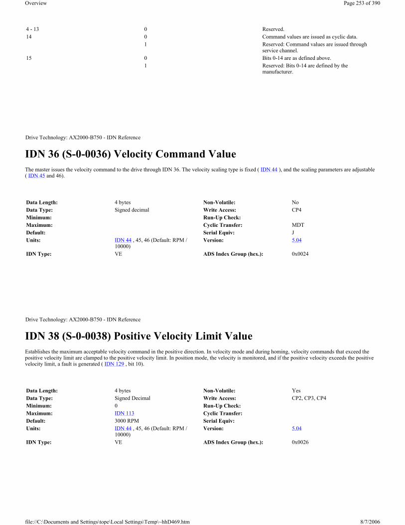
IDN 36 (S-0-0036) Velocity Command Value The master issues the velocity command to the drive through IDN 36. The velocity scaling type is fixed ( IDN 44 ), and the scaling parameters are adjustable ( IDN 45 and 46).
IDN 38 (S-0-0038) Positive Velocity Limit Value Establishes the maximum acceptable velocity command in the positive direction. In velocity mode and during homing, velocity commands that exceed the positive velocity limit are clamped to the positive velocity limit. In position mode, the velocity is monitored, and if the positive velocity exceeds the positive velocity limit, a fault is generated ( IDN 129 , bit 10).
4 - 13 0 Reserved.14 0 Command values are issued as cyclic data.
1 Reserved: Command values are issued through service channel.
15 0 Bits 0-14 are as defined above.1 Reserved: Bits 0-14 are defined by the
manufacturer.
Drive Technology: AX2000-B750 - IDN Reference
Data Length: 4 bytes Non-Volatile: NoData Type: Signed decimal Write Access: CP4Minimum: Run-Up Check:Maximum: Cyclic Transfer: MDTDefault: Serial Equiv: JUnits: IDN 44 , 45, 46 (Default: RPM /
10000)Version: 5.04
IDN Type: VE ADS Index Group (hex.): 0x0024
Drive Technology: AX2000-B750 - IDN Reference
Data Length: 4 bytes Non-Volatile: YesData Type: Signed Decimal Write Access: CP2, CP3, CP4Minimum: 0 Run-Up Check:Maximum: IDN 113 Cyclic Transfer:Default: 3000 RPM Serial Equiv:Units: IDN 44 , 45, 46 (Default: RPM /
10000)Version: 5.04
IDN Type: VE ADS Index Group (hex.): 0x0026
Page 253 of 390Overview
8/7/2006file://C:\Documents and Settings\tope\Local Settings\Temp\~hhD469.htm

IDN 39 (S-0-0039) Negative Velocity Limit Value Establishes the maximum acceptable velocity command in the negative direction. In velocity mode and during homing, velocity commands that exceed the negative velocity limit are clamped to the negative velocity limit. In position mode, the velocity is monitored, and if the negative velocity exceeds the negative velocity limit, a fault is generated ( IDN 129 , bit 10).
IDN 40 (S-0-0040) Velocity Feedback Value The master retrieves the velocity feedback from the drive through IDN 40. The velocity scaling type is fixed ( IDN 44 ), and the scaling parameters are adjustable ( IDN 45 and 46).
IDN 41 (S-0-0041) Homing Velocity The drive's velocity during the “Drive-Controlled Homing” procedure command ( IDN 148 ). The actual homing velocity may be limited by the Bipolar, Positive, or Negative Velocity Limit Values ( IDN 91 , 38, 39 respectively). The velocity scaling type is fixed ( IDN 44 ), and the scaling parameters are adjustable ( IDN 45 and 46).
Drive Technology: AX2000-B750 - IDN Reference
Data Length: 4 bytes Non-Volatile: YesData Type: Signed Decimal Write Access: CP2, CP3, CP4Minimum: – IDN 113 Run-Up Check:Maximum: 0 Cyclic Transfer:Default: – 3000 RPM Serial Equiv: VLIMNUnits: IDN 44 , 45, 46 (Default: RPM /
10000)Version: 5.04
IDN Type: VE ADS Index Group (hex.): 0x0027
Drive Technology: AX2000-B750 - IDN Reference
Data Length: 4 bytes Non-Volatile: NoData Type: Signed decimal Write Access: Read-onlyMinimum: Run-Up Check:Maximum: Cyclic Transfer: ATDefault: Serial Equiv: VUnits: IDN 44 , 45, 46 (Default: RPM /
10000)Version: 5.04
IDN Type: VE ADS Index Group (hex.): 0x0028
Drive Technology: AX2000-B750 - IDN Reference
Data Length: 4 bytes Non-Volatile: YesData Type: Signed decimal Write Access: CP2, CP3, CP4Minimum: 0 Run-Up Check:Maximum: 231 – 1 Cyclic Transfer:
Page 254 of 390Overview
8/7/2006file://C:\Documents and Settings\tope\Local Settings\Temp\~hhD469.htm

IDN 42 (S-0-0042) Homing Acceleration The drive's maximum acceleration and deceleration during the “Drive Controlled Homing” procedure ( IDN 148 ). The homing acceleration is defined as the number of milliseconds to reach the homing velocity.
IDN 43 (S-0-0043) Velocity Polarity Parameter The velocity polarity parameter is used to switch the polarities of velocity data. Polarities are not switched internally but externally, this means on the in- and output of a closed loop system. The motor shaft turns clockwise when there is a positive velocity command and no inversion.
Definition:
Default: 23 RPM Serial Equiv: VREF*32 / (140 * IDN 45 * 10 IDN 46 )
Units: IDN 44 , 45, 46 (Default: RPM / 10000)
Version: 5.04
IDN Type: PS:VE ADS Index Group (hex.): 0x0029
Drive Technology: AX2000-B750 - IDN Reference
Data Length: 4 bytes Non-Volatile: YesData Type: Signed decimal Write Access: CP2, CP3, CP4Minimum: 1 Run-Up Check:Maximum: 32767 Cyclic Transfer:Default: 10 Serial Equiv: ACCR, DECRUnits: IDN 160 , 161, 162 Version: 5.04IDN Type: PS:AD ADS Index Group (hex.): 0x002A
Drive Technology: AX2000-B750 - IDN Reference
Data Length: 2 bytes Non-Volatile: YesData Type: Binary Write Access: CP2Minimum: 0 Run-Up Check:Maximum: 0005H Cyclic Transfer:Default: 0 Serial Equiv: SERCSET (bits 12-15)Units: Version: 5.04IDN Type: VE ADS Index Group (hex.): 0x002B
Bit Description0 Velocity command value 0 = non-inverted
1 = inverted1 Reserved: Additive velocity command value 0 = non-inverted
1 = Reserved (inverted)2 Velocity feedback value 0 = non-inverted
Page 255 of 390Overview
8/7/2006file://C:\Documents and Settings\tope\Local Settings\Temp\~hhD469.htm

IDN 44 (S-0-0044) Velocity Data Scaling Type Defines the scaling options for all velocity data. The scaling types which are supported are indicated in bold-face type. If preferred rotational scaling is selected, the velocity scaling factor ( IDN 45 ) will set to 1 and the velocity data scaling exponent ( IDN 46 ) will set to –4 (refer to IDN 45 and 46).
Definition:
IDN 45 (S-0-0045) Velocity Data Scaling Factor The scaling factor for all velocity data in the drive. The exponent is defined with IDN 46 , so that the LSB weight of all rotational velocity data is derived from the following equation:
The scaling may be defined within the following range: 1x10⁻⁵ to 1x100. IDN 45 and IDN 46 must be integers. If preferred rotational scaling is selected in IDN 44 , the velocity scaling factor (IDN 45) and the velocity data scaling exponent ( IDN 46 ) will fixed set to there default values (refer to IDN 44 ). By the velocity scaling it is possible to get a rounding error in the LSBits.
15-7
Drive Technology: AX2000-B750 - IDN Reference
Data Length: 2 bytes Non-Volatile: YesData Type: Binary Write Access: CP2, CP3Minimum: 0002H Run-Up Check:Maximum: 000AH Cyclic Transfer:Default: 000AH Serial Equiv:Units: Version: 5.04IDN Type: VE ADS Index Group (hex.): 0x002C
Bit Description2 – 0 Scaling Method 000 = Reserved: No Scaling
001 = Reserved: Linear Scaling010 = Rotational Scaling
3 Standard Scaling Type 0 = Preferred Scaling1 = Parameter Scaling
4 Units for Linear Scaling 0 = Meters (m)1 = Inches (in)
4 Units for Rotational Scaling 0 = Revolutions (R)1 = Reserved
5 Time Units 0 = Minutes (min)1 = Reserved: Seconds (s)
615-7 Reserved.
Drive Technology: AX2000-B750 - IDN Reference
Page 256 of 390Overview
8/7/2006file://C:\Documents and Settings\tope\Local Settings\Temp\~hhD469.htm

IDN 46 (S-0-0046) Velocity Data Scaling Exponent The scaling exponent for all velocity data in the drive. Refer to IDN 45 .
IDN 47 (S-0-0047) Position Command Value The master issues position commands to the drive as cyclic data through IDN 47. Position commands written via the service channel do not take affect. The “Position Command Value” has a fixed scaling type ( IDN 76 ) and a fixed resolution ( IDN 79 ).
Data Length: 2 bytes Non-Volatile: NoData Type: Unsigned decimal Write Access: CP2, CP3Minimum: 1 Run-Up Check:Maximum: 10-( IDN 46 ) Cyclic Transfer:Default: 1 Serial Equiv:Units: Version: 5.04IDN Type: VE ADS Index Group (hex.): 0x002D
Drive Technology: AX2000-B750 - IDN Reference
Data Length: 2 bytes Non-Volatile: NoData Type: Signed decimal Write Access: CP2, CP3Minimum: – 5 Run-Up Check:Maximum: – log ( IDN 45 ) Cyclic Transfer:Default: – 4 Serial Equiv:Units: Version: 5.04IDN Type: VE ADS Index Group (hex.): 0x002E
Drive Technology: AX2000-B750 - IDN Reference
Data Length: 4 bytes Non-Volatile: NoData Type: Signed decimal Write Access: CP4Minimum: Run-Up Check:Maximum: Cyclic Transfer: MDTDefault: Serial Equiv:Units: IDN 76 , 77, 78, 79 Version: 5.04IDN Type: PS ADS Index Group (hex.): 0x002F
Page 257 of 390Overview
8/7/2006file://C:\Documents and Settings\tope\Local Settings\Temp\~hhD469.htm

IDN 49 (S-0-0049) Positive Position Limit Switch This IDN defines the maximum position in positive direction. The positive position limit switch is active, when the limit switch is enabled (Refer to IDN 55and IDN 3004 ). If linear scaling is selected in IDN 76 , the positive limit switch will be automatically calculated, with the feed constant IDN 123 and enabled with the enable bit in IDN 55 . When the position command value reaches the limit switch, the drive decelerates to a stop and in the LED the error “F24” ant the warning “n07” are flashing and the fault bit 13 in IDN 11 and also the warning bits in IDN 323 and IDN 12 Bit 13 are set. With linear position scaling the maximum value is 1024 feed constant.
IDN 50 (S-0-0050) Negative Position Limit Switch This IDN defines the minimum position in negative direction. The positive position limit switch is active, when the limit switch is enabled (Refer to IDN 55and IDN 3004 ). If linear scaling is selected in IDN 76 , the positive limit switch will be automatically calculated, with the feed constant IDN 123 and enabled with the enable bit in IDN 55 . When the position command value reach the limit switch, the drive decelerate to a stop and in the LED the error “F24” ant the warning “n06” are flashing and the fault bit 13 in IDN 11 and also the warning bits in IDN 323 and IDN 12 Bit 13 are set. With linear position scaling the maximum value is 1024 feed constant.
IDN 51 (S-0-0051) Position Feedback Value 1 (Motor Feedback) The master retrieves the motor's position feedback from the drive through IDN 51. The scaling type and the resolution will be defined within IDN 76 , 77, 78 and 79.
Drive Technology: AX2000-B750 - IDN Reference
Data Length: 4 bytes Non-Volatile: YesData Type: Signed decimal Write Access: CP2, CP3, CP4Minimum: -231+1 Run-Up Check:Maximum: 231-1 Cyclic Transfer:Default: 0 Serial Equiv: SWE2Units: IDN 76 , 77, 78, 79 Version: 5.04IDN Type: PS ADS Index Group (hex.): 0x0031
Drive Technology: AX2000-B750 - IDN Reference
Data Length: 4 bytes Non-Volatile: YesData Type: Signed decimal Write Access: CP2, CP3, CP4Minimum: -231+1 Run-Up Check:Maximum: 231-1 Cyclic Transfer:Default: 0 Serial Equiv: SWE1Units: IDN 76 , 77, 78, 79 Version: 5.04IDN Type: PS ADS Index Group (hex.): 0x0032
Drive Technology: AX2000-B750 - IDN Reference
Data Length: 4 bytes Non-Volatile: NoData Type: Signed decimal Write Access: Read-only
Page 258 of 390Overview
8/7/2006file://C:\Documents and Settings\tope\Local Settings\Temp\~hhD469.htm
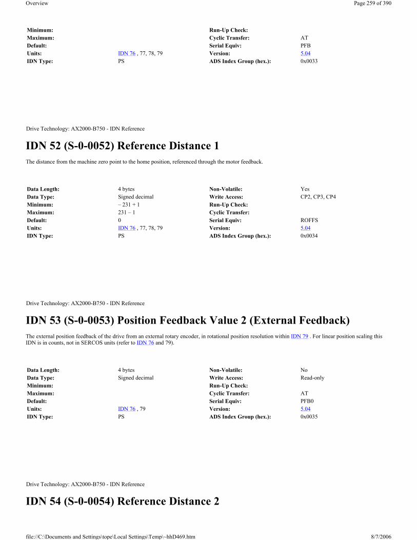
IDN 52 (S-0-0052) Reference Distance 1 The distance from the machine zero point to the home position, referenced through the motor feedback.
IDN 53 (S-0-0053) Position Feedback Value 2 (External Feedback) The external position feedback of the drive from an external rotary encoder, in rotational position resolution within IDN 79 . For linear position scaling this IDN is in counts, not in SERCOS units (refer to IDN 76 and 79).
IDN 54 (S-0-0054) Reference Distance 2
Minimum: Run-Up Check:Maximum: Cyclic Transfer: ATDefault: Serial Equiv: PFBUnits: IDN 76 , 77, 78, 79 Version: 5.04IDN Type: PS ADS Index Group (hex.): 0x0033
Drive Technology: AX2000-B750 - IDN Reference
Data Length: 4 bytes Non-Volatile: YesData Type: Signed decimal Write Access: CP2, CP3, CP4Minimum: – 231 + 1 Run-Up Check:Maximum: 231 – 1 Cyclic Transfer:Default: 0 Serial Equiv: ROFFSUnits: IDN 76 , 77, 78, 79 Version: 5.04IDN Type: PS ADS Index Group (hex.): 0x0034
Drive Technology: AX2000-B750 - IDN Reference
Data Length: 4 bytes Non-Volatile: NoData Type: Signed decimal Write Access: Read-onlyMinimum: Run-Up Check:Maximum: Cyclic Transfer: ATDefault: Serial Equiv: PFB0Units: IDN 76 , 79 Version: 5.04IDN Type: PS ADS Index Group (hex.): 0x0035
Drive Technology: AX2000-B750 - IDN Reference
Page 259 of 390Overview
8/7/2006file://C:\Documents and Settings\tope\Local Settings\Temp\~hhD469.htm

The distance from the machine zero point to the home position for the secondary feedback. If homing is done the position feedback value 2 ( IDN 53 ) contains the value of this IDN (refer to 148).
IDN 55 (S-0-0055) Position Polarity Parameter The position polarity parameter is used to switch the polarities of position data. Polarities are not switched internally but externally, this means on the in- and output of a closed loop system. The motor shaft turns clockwise when there is a positive position command difference and no inversion. Bit 4 disable or enable the SW-Limit switches. If linear scaling of the position data is selected (refer to IDN 76 ), these Bit will automatic set and it is not possible to disable the position limit values (refer to IDN 49 and 50). If the Position limit switches are set, the drive set a software limit switch fault (Bit 13 in IDN 11 ), if the drive reach the not allowed area. A new value in bit 4 will not become active until the parameter is saved to non-volatile memory and a coldstart or warmstart ( IDN 128 procedure is initiated
Definition:
Data Length: 4 bytes Non-Volatile: YesData Type: Signed decimal Write Access: CP2, CP3, CP4Minimum: – 231 + 1 Run-Up Check:Maximum: 231 – 1 Cyclic Transfer:Default: 0 Serial Equiv: ROFFS0Units: IDN 76 , 79 Version: 5.04IDN Type: PS ADS Index Group (hex.): 0x0036
Drive Technology: AX2000-B750 - IDN Reference
Data Length: 2 bytes Non-Volatile: YesData Type: Binary Write Access: CP2Minimum: 0 Run-Up Check:Maximum: 001D H Cyclic Transfer:Default: 0 Serial Equiv: SERCSET (Bits 4 - 11)Units: Version: 5.04IDN Type: VE ADS Index Group (hex.): 0x0037
Bit Description0 Position command value 0 = non-inverted
1 = inverted 1 Reserved: Additive position command value 0 = non-inverted
1 = Reserved (inverted) 2 Position feedback value 1 0 = non-inverted
1 = inverted 3 Position feedback value 2 0 = non-inverted
1 = inverted 4 Position limit values 0 = disabled
1 = enabled 15-5 Reserved
Page 260 of 390Overview
8/7/2006file://C:\Documents and Settings\tope\Local Settings\Temp\~hhD469.htm

IDN 57 (S-0-0057) Position Window Defines the maximum absolute distance between the position command value and the position feedback value. When the following error is within the “Position Window,” the drive sets the status flag “In Position” ( IDN 13 , bit 6). This function is only active while the drive is in position control. The “In Position” flag may be selected as a RTS bit through IDN 336 (refer to IDN 159 , 189, 336).
IDN 59 (S-0-0059) Position Switch Flag Parameter The position switch flag parameter depends on the position feedback value, the settings of the “Position Switch Polarity Parameter” ( IDN 3043 and the “Kind of Position Switch Parameter” ( IDN 3044 . The behavior of the position switch flag bits are described below (please refer also to the IDN 3043 and IDN 3044 ). A digital output may also be configured to duplicate a position switch flag through the “Digital Output 1 Mode” ( IDN 3005 ), the “Digital Output 1 Trigger” ( IDN 3007 ), the “Digital Output 2 Mode” ( IDN 3006 ) and the “Digital Output 2 Trigger” ( IDN 3008 ).
The corresponding bits of IDN 3043 and IDN 3044 are set to “0”, which is the default. Then the associated flag bit is set to “0” if the position feedback value is smaller than the position switching point. The associated flag is set to “1” if the position feedback value is greater than or equal to the position switching point.
The corresponding bits of IDN 3043 is set to “1” and of IDN 3044 is set to “0”. Then the associated flag bit is set to “1” if the position feedback value is smaller than the position switching point. The associated flag is set to “0” if the position feedback value is greater than or equal to the position switching point
If the corresponding bit of IDN 3044 is set to “1”, then the associated flag is checked once according to the polarity setting of IDN 3043 and latched till the associated flag is enabled again.
Definition:
Drive Technology: AX2000-B750 - IDN Reference
Data Length: 4 bytes Non-Volatile: NoData Type: Unsigned decimal Write Access: CP2, CP3, CP4Minimum: Run-Up Check:Maximum: Cyclic Transfer:Default: 7FFF FFFF Serial Equiv:Units: IDN 76 , 77, 78, 79 Version: 5.04IDN Type: PS ADS Index Group (hex.): 0x0039
Drive Technology: AX2000-B750 - IDN Reference
Data Length: 2 bytes Non-Volatile: NoData Type: Binary Write Access: Read-onlyMinimum: 0000H Run-Up Check:Maximum: 00FFH Cyclic Transfer: ATDefault: Serial Equiv: M POSRSTATUnits: Version: 5.04IDN Type: PS ADS Index Group (hex.): 0x003B
Bit DescriptionLSB 0 Position switch point 1 ( IDN 60 )1 Position switch point 2 ( IDN 61 )2 Position switch point 3 ( IDN 62 )
Page 261 of 390Overview
8/7/2006file://C:\Documents and Settings\tope\Local Settings\Temp\~hhD469.htm

IDN 60 (S-0-0060) Position Switch Point 1 Each position switch point IDN defines a feedback position that determines the state of a corresponding position status flag within IDN 59 (refer to IDN 59 ).
IDN 61 (S-0-0061) Position Switch Point 2 Each position switch point IDN defines a feedback position that determines the state of a corresponding position status flag within IDN 59 (refer to IDN 59 ).
IDN 62 (S-0-0062) Position Switch Point 3
3 Position switch point 4 ( IDN 63 )4 Position switch point 5 ( IDN 64 )5 Position switch point 6 ( IDN 65 )6 Position switch point 7 ( IDN 66 )7 Position switch point 8 ( IDN 67 )8 – 15 Reserved.
Drive Technology: AX2000-B750 - IDN Reference
Data Length: 4 bytes Non-Volatile: NoData Type: Signed decimal Write Access: CP2, CP3, CP4Minimum: Run-Up Check:Maximum: Cyclic Transfer: MDT (60 + 61)Default: 0 Serial Equiv: P1, P2, P3, P4, P5, P6, P7 and P8Units: IDN 76 , 77, 78, 79 Version: 5.04IDN Type: PS ADS Index Group (hex.): 0x003C
Drive Technology: AX2000-B750 - IDN Reference
Data Length: 4 bytes Non-Volatile: NoData Type: Signed decimal Write Access: CP2, CP3, CP4Minimum: Run-Up Check:Maximum: Cyclic Transfer: MDT (60 + 61)Default: 0 Serial Equiv: P1, P2, P3, P4, P5, P6, P7 and P8Units: IDN 76 , 77, 78, 79 Version: 5.04IDN Type: PS ADS Index Group (hex.): 0x003D
Drive Technology: AX2000-B750 - IDN Reference
Page 262 of 390Overview
8/7/2006file://C:\Documents and Settings\tope\Local Settings\Temp\~hhD469.htm

Each position switch point IDN defines a feedback position that determines the state of a corresponding position status flag within IDN 59 (refer to IDN 59 ).
IDN 63 (S-0-0063) Position Switch Point 4 Each position switch point IDN defines a feedback position that determines the state of a corresponding position status flag within IDN 59 (refer to IDN 59 ).
IDN 64 (S-0-0064) Position Switch Point 5 Each position switch point IDN defines a feedback position that determines the state of a corresponding position status flag within IDN 59 (refer to IDN 59 ).
Data Length: 4 bytes Non-Volatile: NoData Type: Signed decimal Write Access: CP2, CP3, CP4Minimum: Run-Up Check:Maximum: Cyclic Transfer: MDT (60 + 61)Default: 0 Serial Equiv: P1, P2, P3, P4, P5, P6, P7 and P8Units: IDN 76 , 77, 78, 79 Version: 5.04IDN Type: PS ADS Index Group (hex.): 0x003E
Drive Technology: AX2000-B750 - IDN Reference
Data Length: 4 bytes Non-Volatile: NoData Type: Signed decimal Write Access: CP2, CP3, CP4Minimum: Run-Up Check:Maximum: Cyclic Transfer: MDT (60 + 61)Default: 0 Serial Equiv: P1, P2, P3, P4, P5, P6, P7 and P8Units: IDN 76 , 77, 78, 79 Version: 5.04IDN Type: PS ADS Index Group (hex.): 0x003F
Drive Technology: AX2000-B750 - IDN Reference
Data Length: 4 bytes Non-Volatile: NoData Type: Signed decimal Write Access: CP2, CP3, CP4Minimum: Run-Up Check:Maximum: Cyclic Transfer: MDT (60 + 61)Default: 0 Serial Equiv: P1, P2, P3, P4, P5, P6, P7 and P8Units: IDN 76 , 77, 78, 79 Version: 5.04IDN Type: PS ADS Index Group (hex.): 0x0040
Page 263 of 390Overview
8/7/2006file://C:\Documents and Settings\tope\Local Settings\Temp\~hhD469.htm

IDN 65 (S-0-0065) Position Switch Point 6 Each position switch point IDN defines a feedback position that determines the state of a corresponding position status flag within IDN 59 (refer to IDN 59 ).
IDN 66 (S-0-0066) Position Switch Point 7 Each position switch point IDN defines a feedback position that determines the state of a corresponding position status flag within IDN 59 (refer to IDN 59 ).
IDN 67 (S-0-0067) Position Switch Point 8 Each position switch point IDN defines a feedback position that determines the state of a corresponding position status flag within IDN 59 (refer to IDN 59 ).
Drive Technology: AX2000-B750 - IDN Reference
Data Length: 4 bytes Non-Volatile: NoData Type: Signed decimal Write Access: CP2, CP3, CP4Minimum: Run-Up Check:Maximum: Cyclic Transfer: MDT (60 + 61)Default: 0 Serial Equiv: P1, P2, P3, P4, P5, P6, P7 and P8Units: IDN 76 , 77, 78, 79 Version: 5.04IDN Type: PS ADS Index Group (hex.): 0x0041
Drive Technology: AX2000-B750 - IDN Reference
Data Length: 4 bytes Non-Volatile: NoData Type: Signed decimal Write Access: CP2, CP3, CP4Minimum: Run-Up Check:Maximum: Cyclic Transfer: MDT (60 + 61)Default: 0 Serial Equiv: P1, P2, P3, P4, P5, P6, P7 and P8Units: IDN 76 , 77, 78, 79 Version: 5.04IDN Type: PS ADS Index Group (hex.): 0x0042
Drive Technology: AX2000-B750 - IDN Reference
Data Length: 4 bytes Non-Volatile: NoData Type: Signed decimal Write Access: CP2, CP3, CP4Minimum: Run-Up Check:Maximum: Cyclic Transfer: MDT (60 + 61)Default: 0 Serial Equiv: P1, P2, P3, P4, P5, P6, P7 and P8Units: IDN 76 , 77, 78, 79 Version: 5.04IDN Type: PS ADS Index Group (hex.): 0x0043
Page 264 of 390Overview
8/7/2006file://C:\Documents and Settings\tope\Local Settings\Temp\~hhD469.htm

IDN 76 (S-0-0076) Position Data Scaling Type Defines the scaling options for all position data. The supported scaling types are indicated in bold-face type. The following scaling types are available : 0001(Hex), 0081(Hex), 0009(Hex), 0089(Hex), 000A(Hex) and 008A(Hex). If linear scaling is selected without modulo format on (bit 7 = 1), the software limit switches are automatic switched on (refer to IDN 49 , 50, 55 and IDN 3004 ). If modulo format is selected, the drive operates without interpolation. If rotational scaling is selected and the rotational position resolution ( IDN 79 ) is different from 1048576 or 65536 the modulo format must switch on, this will check during runup. A change of bit 7 will initiate a warmstart procedure (refer to IDN 128 during runup. With set the operation mode within IDN 32 or 33 to position control with external feedback, this IDN will set to 004A(Hex) as a fixed setting. The drive can only operate with a fixed rotational scaling for the position data in this case (refer to IDN 79 ).
Definition:
IDN 77 (S-0-0077) Linear Position Data Scaling Factor
Drive Technology: AX2000-B750 - IDN Reference
Data Length: 2 bytes Non-Volatile: YesData Type: Binary Write Access: CP2Minimum: 0001H Run-Up Check: CP3Maximum: 008AH Cyclic Transfer:Default: 000AH Serial Equiv: SERCSET (Bits 24 – 31)Units: Version: 5.04IDN Type: PS ADS Index Group (hex.): 0x004C
Bit Description Value Description2 - 0 Scaling Method 000
001
010
Reserved: No Scaling
Linear Scaling
Rotational Scaling 3 Standard Scaling Type 0
1
Preferred Scaling
Parameter Scaling 4 Reserved: Units for Linear Scaling 0
1
Meters (m)
Inches (in) 4 Units for Rotational Scaling 0
1
Degrees
Reserved 5 Reserved 6 Data Reference 0
1
At the Motor Shaft
At the Load (Only for rotational scaling)
7 Processing Format 0
1
Absolute Format
Modulo Format (See IDN 103 )15-8 Reserved
Drive Technology: AX2000-B750 - IDN Reference
Page 265 of 390Overview
8/7/2006file://C:\Documents and Settings\tope\Local Settings\Temp\~hhD469.htm

This parameter defines the scaling factor for all position data in the drive, when linear scaling in IDN 76 is selected.
IDN 78 (S-0-0078) Linear Position Data Scaling Exponent This parameter defines the scaling exponent for all position data in the drive, when linear scaling in IDN 76 is selected. Refer to IDN 77 .
IDN 79 (S-0-0079) Rotational Position Resolution The rotational position resolution for all position data in the drive. The LSB weight of rotational position data is determined by the following equation:
If the rotational position resolution is different from 65536 or 1048576, it is necessary that the modulo format is switched on in IDN 76 . Only the values 65536 and 1048576 could save in the non-volatile memory. If position control with external feedback is selected, the drive will calculate the rotational position resolution with the resolution of the rotational feedback 2 ( IDN 117 ). This value for IDN 79 is then write protected and could only read by the master. By using parameter 121 and 122 the minimum changes to min: 100 x ( IDN 122 / IDN 121 )and the maximum to max: 100 000 000 x ( IDN 122 / IDN 121 )
Data Length: 2 bytes Non-Volatile: YesData Type: Unsigned decimal Write Access: Read-onlyMinimum: Run-Up Check:Maximum: Cyclic Transfer:Default: 1 Serial Equiv:Units: Version: 5.04IDN Type: PS ADS Index Group (hex.): 0x004D
Drive Technology: AX2000-B750 - IDN Reference
Data Length: 2 bytes Non-Volatile: YesData Type: Signed decimal Write Access: Read-onlyMinimum: Run-Up Check:Maximum: Cyclic Transfer:Default: -7 Serial Equiv:Units: Version: 5.04IDN Type: PS ADS Index Group (hex.): 0x004E
Drive Technology: AX2000-B750 - IDN Reference
Data Length: 4 bytes Non-Volatile: YesData Type: Unsigned decimal Write Access: CP2Minimum: 100 Run-Up Check:Maximum: 100 000 000 Cyclic Transfer:Default: 1048576 Serial Equiv: PRBASE
Page 266 of 390Overview
8/7/2006file://C:\Documents and Settings\tope\Local Settings\Temp\~hhD469.htm

IDN 80 (S-0-0080) Torque Command Value The master issues torque commands to the drive as cyclic data through IDN 80. Torque commands written via the service channel do not take affect.
IDN 84 (S-0-0084) Torque Feedback Value The master retrieves the motor's torque feedback from the drive through IDN 84.
IDN 86 (S-0-0086) Torque/Force Data Scaling Type Defines the scaling options for all torque or force data. The scaling types which are supported are indicated in bold-face type. The weight of the LSB for percentage scaling is defined as 0.1% of the motor’s continuous current ( IDN 111 ).
Units: Counts / Revolution Version: 5.04IDN Type: PS ADS Index Group (hex.): 0x004F
Drive Technology: AX2000-B750 - IDN Reference
Data Length: 2 bytes Non-Volatile: NoData Type: Signed decimal Write Access: CP4Minimum: Run-Up Check:Maximum: Cyclic Transfer: MDTDefault: Serial Equiv: ICMD ( (1000 / MICONT)Units: IDN 86 Version: 5.04IDN Type: CT ADS Index Group (hex.): 0x0050
Drive Technology: AX2000-B750 - IDN Reference
Data Length: 2 bytes Non-Volatile: NoData Type: Signed decimal Write Access: Read-onlyMinimum: Run-Up Check:Maximum: Cyclic Transfer: ATDefault: Serial Equiv: I ( (1000 / MICONT)Units: IDN 86 Version: 5.04IDN Type: CT ADS Index Group (hex.): 0x0054
Drive Technology: AX2000-B750 - IDN Reference
Page 267 of 390Overview
8/7/2006file://C:\Documents and Settings\tope\Local Settings\Temp\~hhD469.htm

Definition:
IDN 88 (S-0-0088) Receive to Receive Recovery Time The time required by the drive between the end of the MDT and the beginning of the MST.
Data Length: 2 bytes Non-Volatile: YesData Type: Binary Write Access: Read-onlyMinimum: Run-Up Check:Maximum: Cyclic Transfer:Default: 0 Serial Equiv:Units: Version: 5.04IDN Type: CT ADS Index Group (hex.): 0x0056
Bit Description2 – 0 Scaling Method 000=Percentage Scaling
001=Reserved: Linear Scaling
010=Reserved: Rotational Scaling 3 Reserved: Standard Scaling Type 0=Preferred Scaling
1=Parameter Scaling 4 Reserved: Units for Force 0=Newton (N)
1=Pound Force (lbf) 4 Reserved: Units for Torque 0=Newton-Meter (Nm)
1=Inch Pound-Force (in-lbf) 5 Reserved6 Data Reference 0=At the Motor Shaft
1=Reserved: At the Load 15-7 Reserved
Drive Technology: AX2000-B750 - IDN Reference
Data Length: 2 bytes Non-Volatile: YesData Type: Unsigned decimal Write Access: Read-onlyMinimum: Run-Up Check:Maximum: Cyclic Transfer:Default: 50 Serial Equiv:Units: µs Version: 5.04IDN Type: SC ADS Index Group (hex.): 0x0058
Drive Technology: AX2000-B750 - IDN Reference
Page 268 of 390Overview
8/7/2006file://C:\Documents and Settings\tope\Local Settings\Temp\~hhD469.htm

IDN 89 (S-0-0089) MDT Transmission Starting Time The time at which the master should transmit the MDT, after the end of the MST, during CP3 and CP4. The MDT Transmission Starting Time must be downloaded from the master during CP2. The “MDT Transmission Starting Time” is limited by the CCT ( IDN 2 ), the “Transmit/Receive Transmission Time” ( IDN 4 ) the “AT Transmission Starting Time” ( IDN 6 ) and the “Receive to Receive Recovery Time” ( IDN 88 ) according to the following restrictions.
IDN 89 ( IDN 6 + AT Transmission Time + AT Jitter + IDN 4 + MDT Jitter
IDN 89 ( IDN 2 – max IDN 88 from all drives – MDT Transmission Time
– MST Transmission Time – MDT Jitter – CCT Jitter
IDN 90 (S-0-0090) Command Value Processing Time The minimum time required by the drive from the end of the MDT to the point at which the received command values may be used by the drive.
IDN 91 (S-0-0091) Bipolar Velocity Limit Establishes the maximum acceptable velocity command in both the clockwise and counter-clockwise directions. In velocity mode and during homing, velocity commands that exceed the bipolar velocity limit are clamped to the bipolar velocity limit. In position mode, the velocity is monitored, and if the velocity exceeds the bipolar velocity limit, a fault is generated ( IDN 129 , bit 10).
The “Bipolar Velocity Limit” (IDN 91) is linked to the “Positive and Negative Velocity Limit Values” ( IDN 38 and IDN 39 ). When a value is written to IDN 91, the same value is also written to IDN 38 and IDN 39 (with the appropriate signs). IDN 38 and IDN 39 must have the same absolute value in order for IDN 91 to be valid. If they do not have the same absolute value when IDN 91 is read, then the drive will return error message 7008, “Invalid Data” for IDN 91.
Data Length: 2 bytes Non-Volatile: NoData Type: Unsigned decimal Write Access: CP2Minimum: Run-Up Check: CP2Maximum: Cyclic Transfer:Default: None Serial Equiv:Units: µs Version: 5.04IDN Type: SC ADS Index Group (hex.): 0x0059
Drive Technology: AX2000-B750 - IDN Reference
Data Length: 2 bytes Non-Volatile: YesData Type: Unsigned decimal Write Access: Read-onlyMinimum: Run-Up Check:Maximum: Cyclic Transfer:Default: 50 Serial Equiv:Units: µs Version: 5.04IDN Type: SC ADS Index Group (hex.): 0x005A
Drive Technology: AX2000-B750 - IDN Reference
Page 269 of 390Overview
8/7/2006file://C:\Documents and Settings\tope\Local Settings\Temp\~hhD469.htm

IDN 92 (S-0-0092) Bipolar Torque Limit Defines the maximum torque limit in both the clockwise and counter-clockwise directions.
IDN 95 (S-0-0095) Diagnostic Message The master may read a text message that describes the status of the drive.
Data Length: 4 bytes Non-Volatile: YesData Type: Signed decimal Write Access: CP2, CP3, CP4Minimum: 0 Run-Up Check:Maximum: IDN 113 Cyclic Transfer:Default: 3000 RPM Serial Equiv: VLIM, VLIMNUnits: IDN 44 ,45,46 (Default: RPM / 10
000)Version: 5.04
IDN Type: VE:FS ADS Index Group (hex.): 0x005B
Drive Technology: AX2000-B750 - IDN Reference
Data Length: 2 bytes Non-Volatile: YesData Type: Unsigned decimal Write Access: CP2, CP3, CP4Minimum: 0 Run-Up Check:Maximum: Minimum of IDN 109 and IDN 110 Cyclic Transfer:Default: Minimum of IDN 109 and IDN 110 Serial Equiv: (IPEAK)Units: IDN 86 Version: 5.04IDN Type: CT:FS ADS Index Group (hex.): 0x005C
Drive Technology: AX2000-B750 - IDN Reference
Data Length: 1 byte elements, variable length array Non-Volatile: NoData Type: Text Write Access: Read-onlyMinimum: Run-Up Check:Maximum: Cyclic Transfer:Default: Serial Equiv: SSTATUnits: Version: 5.04IDN Type: FS:MT ADS Index Group (hex.): 0x005F
Drive Technology: AX2000-B750 - IDN Reference
Page 270 of 390Overview
8/7/2006file://C:\Documents and Settings\tope\Local Settings\Temp\~hhD469.htm

IDN 96 (S-0-0096) Slave Arrangement The SERCOS address of the drive is contained in both the upper and lower bytes of this IDN. The drive’s address may range from 0 to 63 and may be selected through the front panel of the drive. A drive with an address of zero is a repeater on the SERCOS ring and does not participate in the communication phase run-up. A new drive has a default address of zero.
IDN 97 (S-0-0097) Class 2 Diagnostic Mask A mask for the C2D ( IDN 12 ). When a warning condition within IDN 12 changes state, the C2D change bit (AT status word, bit 12) is set. The warning bits within IDN 12 are not latched (i.e. they will automatically set or reset as warning conditions change). The C2D change bit is reset when IDN 12 is read through the service channel. IDN 97 may be used to mask the effect of a particular warning condition on the C2D change bit: when a masked warning changes state, the C2D change bit will not be set. However, the warning bits in IDN 12 will continue to change state according to the warning conditions. When a bit in IDN 97 is clear, the corresponding bit in IDN 12 is masked.
IDN 98 (S-0-0098) Class 3 Diagnostic Mask A mask for the C3D ( IDN 13 ). When a status condition within IDN 13 changes state, the C3D change bit (AT status word, bit 11) is set. The status bits within IDN 13 are not latched (i.e. they will automatically set or reset as status conditions change). The C3D change bit is reset when IDN 13 is read through the service channel. IDN 98 may be used to mask the effect of a particular status condition on the C3D change bit: when a masked status changes state, the C3D change bit will not be set. However, the status bits in IDN 13 will continue to change state according to the status conditions. When a bit in IDN 98 is clear, the corresponding bit in IDN 13 is masked.
Data Length: 2 bytes Non-Volatile: YesData Type: Hexadecimal Write Access: Read-onlyMinimum: Run-Up Check:Maximum: Cyclic Transfer:Default: Serial Equiv: (ADDR << 8) | ADDRUnits: Version: 5.04IDN Type: SC:MT ADS Index Group (hex.): 0x0060
Drive Technology: AX2000-B750 - IDN Reference
Data Length: 2 bytes Non-Volatile: NoData Type: Binary Write Access: CP2, CP3, CP4Minimum: Run-Up Check:Maximum: Cyclic Transfer:Default: 1111 1111 1111 1111 Serial Equiv:Units: Version: 5.04IDN Type: SC:MT ADS Index Group (hex.): 0x0061
Drive Technology: AX2000-B750 - IDN Reference
Data Length: 2 bytes Non-Volatile: NoData Type: Binary Write Access: CP2, CP3, CP4Minimum: Run-Up Check:
Page 271 of 390Overview
8/7/2006file://C:\Documents and Settings\tope\Local Settings\Temp\~hhD469.htm

IDN 99 (S-0-0099) Procedure: Reset Class 1 Diagnostic Attempts to clear the latched faults contained in IDN 11 , IDN 14 and IDN 129 . Faults that are still active are not cleared. If all the faults are cleared successfully, the C1D status bit (AT bit 13) is also cleared. The fault reset procedure will fail if faults have been latched and the master has not reset the drive enable control bits (MDT bits 13-15). Some faults specified in IDN 11 and IDN 129 require a coldstart, which IDN 99 performs automatically when required. The IDN 99 procedure will not reset faults if MDT bits 14 and 15 are set while CP3 or CP4.
IDN 100 (S-0-0100) Velocity Loop Proportional Gain The proportional gain for the proportional-integral velocity loop controller. Typical gain values are between 10 and 20. If the gain is too low, then the drive may respond slowly or have poor damping. If the value is too high, then the drive may whistle or run roughly.
Maximum: Cyclic Transfer:Default: 1111 1111 1111 1111 Serial Equiv:Units: Version: 5.04IDN Type: SC:MT ADS Index Group (hex.): 0x0062
Drive Technology: AX2000-B750 - IDN Reference
Data Length: 2 bytes Non-Volatile: NoData Type: Binary Write Access: CP2, CP3, CP4Minimum: Run-Up Check:Maximum: Cyclic Transfer:Default: 0 Serial Equiv:Units: Version: 5.04IDN Type: FS:MT ADS Index Group (hex.): 0x0063
Drive Technology: AX2000-B750 - IDN Reference
Data Length: 2 bytes Non-Volatile: YesData Type: Unsigned decimal Write Access: CP2, CP3, CP4Minimum: 0 Run-Up Check:Maximum: 200 Cyclic Transfer:Default: 1 Serial Equiv: GV * 100Units: Version: 5.04IDN Type: VE ADS Index Group (hex.): 0x0064
Drive Technology: AX2000-B750 - IDN Reference
Page 272 of 390Overview
8/7/2006file://C:\Documents and Settings\tope\Local Settings\Temp\~hhD469.htm

IDN 101 (S-0-0101) Velocity Loop Integral Action Time The integral action time for the proportional-integral velocity loop controller. When IDN 101 is zero, the integrator is switched off. If the value is too low, then the drive may run roughly or may have a large overshoot when coupled to a high-inertia load. If the value is too high, the drive response may be sluggish.
IDN 103 (S-0-0103) Modulo Value If the modulo format is on ( IDN 76 bit 7 = 1), the modulo value determines at which numeric value the position data roll over to 0. The following conditions for the modulo value will check during runup:
If linear scaling and modulo format is selected within IDN 76 and the feed constant IDN 123 is smaller then 2^20, the modulo value must be smaller then 1024 * IDN 123 .
If rotational scaling and modulo format is selected within IDN 76 and rotational position resolution IDN 79 is smaller then 2^20, the modulo value must be smaller then 1024 * IDN 79 .
If rotational scaling and modulo format is selected within IDN 76 and rotational position resolution IDN 79 is greater then 2^20, the modulo value must be smaller then 2^50 / IDN 79 .
IDN 104 (S-0-0104) Position Loop Proportional Gain The proportional gain for the proportional-integral position loop controller. If the value is too low, the settling time may be too long, and the drive may be too sluggish. If the value is too high, the drive may be noisy and may oscillate.
Data Length: 2 bytes Non-Volatile: YesData Type: Unsigned decimal Write Access: CP2, CP3, CP4Minimum: 0 Run-Up Check:Maximum: 10 000 Cyclic Transfer:Default: 100 Serial Equiv: GVTN * 10Units: 0.1 ms Version: 5.04IDN Type: VE ADS Index Group (hex.): 0x0065
Drive Technology: AX2000-B750 - IDN Reference
Data Length: 4 bytes Non-Volatile: NoData Type: Unsigned decimal Write Access: CP2, CP3Minimum: 1 Run-Up Check: CP3Maximum: 2^31-1 Cyclic Transfer:Default: 2^31-1 Serial Equiv: ERNDUnits: IDN 76 , 77, 78, 79 Version: 5.04IDN Type: PS ADS Index Group (hex.): 0x0067
Drive Technology: AX2000-B750 - IDN Reference
Data Length: 2 bytes Non-Volatile: Yes
Page 273 of 390Overview
8/7/2006file://C:\Documents and Settings\tope\Local Settings\Temp\~hhD469.htm

IDN 105 (S-0-0105) Position Loop Integral Action Time The integral time for the proportional-integral position loop controller.
IDN 106 (S-0-0106) Current Loop Proportional Gain 1 The proportional gain for the torque producing current (D) within the proportional-integral current loop controller.
IDN 107 (S-0-0107) Current Loop Integral Action Time 1
Data Type: Unsigned decimal Write Access: CP2, CP3, CP4Minimum: 60 Run-Up Check:Maximum: 60 000 Cyclic Transfer:Default: 900 Serial Equiv: GP * 6000Units: 0.01 (m/min)/mm ( 0.01 (in/min)/mil Version: 5.04IDN Type: PS ADS Index Group (hex.): 0x0068
Drive Technology: AX2000-B750 - IDN Reference
Data Length: 2 bytes Non-Volatile: YesData Type: Unsigned decimal Write Access: CP2, CP3, CP4Minimum: 10 Run-Up Check:Maximum: 2 000 Cyclic Transfer:Default: 500 Serial Equiv: GPTN * 10Units: 0.1 ms Version: 5.04IDN Type: PS ADS Index Group (hex.): 0x0069
Drive Technology: AX2000-B750 - IDN Reference
Data Length: 2 bytes Non-Volatile: YesData Type: Unsigned decimal Write Access: CP2, CP3, CP4Minimum: 1 Run-Up Check:Maximum: 3 000 Cyclic Transfer:Default: 100 Serial Equiv: MLGQ * 100Units: Version: 5.04IDN Type: CT ADS Index Group (hex.): 0x006A
Drive Technology: AX2000-B750 - IDN Reference
Page 274 of 390Overview
8/7/2006file://C:\Documents and Settings\tope\Local Settings\Temp\~hhD469.htm
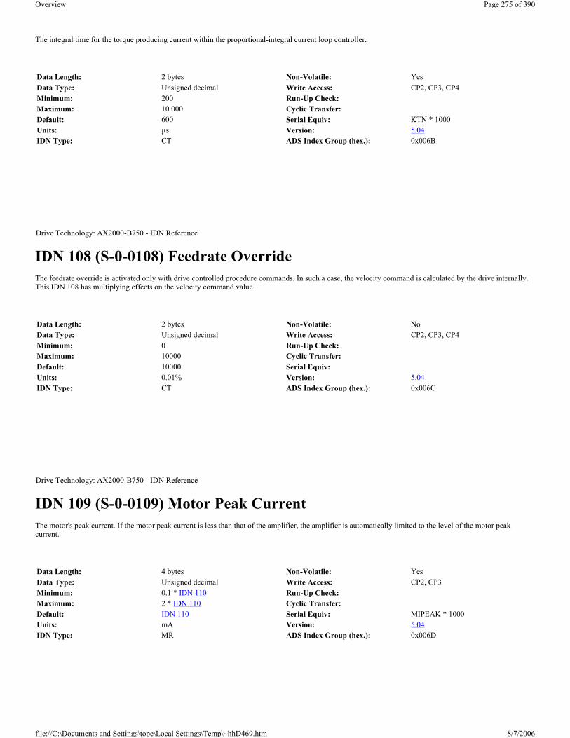
The integral time for the torque producing current within the proportional-integral current loop controller.
IDN 108 (S-0-0108) Feedrate Override The feedrate override is activated only with drive controlled procedure commands. In such a case, the velocity command is calculated by the drive internally. This IDN 108 has multiplying effects on the velocity command value.
IDN 109 (S-0-0109) Motor Peak Current The motor's peak current. If the motor peak current is less than that of the amplifier, the amplifier is automatically limited to the level of the motor peak current.
Data Length: 2 bytes Non-Volatile: YesData Type: Unsigned decimal Write Access: CP2, CP3, CP4Minimum: 200 Run-Up Check:Maximum: 10 000 Cyclic Transfer:Default: 600 Serial Equiv: KTN * 1000Units: µs Version: 5.04IDN Type: CT ADS Index Group (hex.): 0x006B
Drive Technology: AX2000-B750 - IDN Reference
Data Length: 2 bytes Non-Volatile: NoData Type: Unsigned decimal Write Access: CP2, CP3, CP4Minimum: 0 Run-Up Check:Maximum: 10000 Cyclic Transfer:Default: 10000 Serial Equiv:Units: 0.01% Version: 5.04IDN Type: CT ADS Index Group (hex.): 0x006C
Drive Technology: AX2000-B750 - IDN Reference
Data Length: 4 bytes Non-Volatile: YesData Type: Unsigned decimal Write Access: CP2, CP3Minimum: 0.1 * IDN 110 Run-Up Check:Maximum: 2 * IDN 110 Cyclic Transfer:Default: IDN 110 Serial Equiv: MIPEAK * 1000Units: mA Version: 5.04IDN Type: MR ADS Index Group (hex.): 0x006D
Page 275 of 390Overview
8/7/2006file://C:\Documents and Settings\tope\Local Settings\Temp\~hhD469.htm

IDN 110 (S-0-0110) Amplifier Peak Current The amplifier's peak current. This value is defined by the hardware and is set to twice the continuous rated current of the drive.
IDN 111 (S-0-0111) Motor Continuous Stall Current The current at which the motor produces the continuous standstill torque, according to the motor specification sheet. This parameter is used as a reference for all torque data and for determining motor-related current values from torque data.
IDN 112 (S-0-0112) Amplifier Rated Current The amplifier's continuous current rating. This hardware-defined variable is automatically determined by the drive.
Drive Technology: AX2000-B750 - IDN Reference
Data Length: 4 bytes Non-Volatile: YesData Type: Unsigned decimal Write Access: Read-onlyMinimum: Run-Up Check:Maximum: Cyclic Transfer:Default: Hardware defined Serial Equiv: DIPEAK * 1000Units: mA Version: 5.04IDN Type: CT ADS Index Group (hex.): 0x006E
Drive Technology: AX2000-B750 - IDN Reference
Data Length: 4 bytes Non-Volatile: YesData Type: Unsigned decimal Write Access: CP2, CP3Minimum: 0.1 * IDN 112 Run-Up Check:Maximum: 2.0 * IDN 112 Cyclic Transfer:Default: IDN 112 Serial Equiv: MICONT * 1000Units: mA Version: 5.04IDN Type: MR ADS Index Group (hex.): 0x006F
Drive Technology: AX2000-B750 - IDN Reference
Data Length: 4 bytes Non-Volatile: YesData Type: Unsigned decimal Write Access: Read-onlyMinimum: Run-Up Check:Maximum: Cyclic Transfer:Default: Hardware defined Serial Equiv: DICONT * 1000Units: mA Version: 5.04IDN Type: CT ADS Index Group (hex.): 0x0070
Page 276 of 390Overview
8/7/2006file://C:\Documents and Settings\tope\Local Settings\Temp\~hhD469.htm

IDN 113 (S-0-0113) Maximum Motor Speed The motor's maximum recommended speed, as listed in the motor specification sheet provided by the manufacturer.
IDN 114 (S-0-0114) System Load Limit The system’s continuous load rating. The continuous load rating is defined as a percentage of the system’s continuous current. When the load limit is exceeded, the drive sets the overload warning bit in the C2D ( IDN 12 , bit 0). If the load limit is exceeded by 15%, the drive sets the overload shutdown bit in C1D (bit 0).
IDN 116 (S-0-0116) Resolution of Rotational Feedback 1 (Motor Feedback) The motor's rotary feedback resolution (refer to IDN 79 ).
Drive Technology: AX2000-B750 - IDN Reference
Data Length: 4 bytes Non-Volatile: YesData Type: Unsigned decimal Write Access: CP2, CP3Minimum: 0 Run-Up Check:Maximum: 12000 RPM Cyclic Transfer:Default: 3000 RPM Serial Equiv: MSPEEDUnits: IDN 44 ,45,46 (Default: RPM / 10000) Version: 5.04IDN Type: MR ADS Index Group (hex.): 0x0071
Drive Technology: AX2000-B750 - IDN Reference
Data Length: 2 bytes Non-Volatile: YesData Type: Unsigned decimal Write Access: CP2, CP3, CP4Minimum: 0 Run-Up Check:Maximum: 100 Cyclic Transfer:Default: 80 Serial Equiv: I2TLIMUnits: % of min ( IDN 111 , 112, or P3020) Version: 5.04IDN Type: CT: FS ADS Index Group (hex.): 0x0072
Drive Technology: AX2000-B750 - IDN Reference
Page 277 of 390Overview
8/7/2006file://C:\Documents and Settings\tope\Local Settings\Temp\~hhD469.htm

IDN 117 (S-0-0117) Resolution of Rotational Feedback 2 (External Feedback) The resolution of the rotational feedback 2 contains the cycles per revolution of an rotary encoder as an external feedback ( IDN 53 ). The resolution of the external position feedback depends on this parameter and the multiplication factor 2 ( IDN 257 ). The resolution could be calculated with the following calculation rule: resolution = external feedback (IDN117) x 4 x multiplication factor 2 ( IDN 257 ).The maximum resolution is set within IDN 79 divide by 4, the drive checks during runup, that the setting will not give a bigger value. In this case the drive automatically calculates a new multiplication factor 2 ( IDN 257 ).
IDN 119 (S-0-0119) Current Loop Proportional Gain 2 The proportional gain for the field producing current (D) within the proportional-integral current loop controller. This gain has the same value within the proportional gain 1 in the torque producing loop controller (see also IDN 106 ).
Data Length: 4 bytes Non-Volatile: YesData Type: Unsigned decimal Write Access: Read-onlyMinimum: 65536 Run-Up Check:Maximum: 1048576 Cyclic Transfer:Default: 1048576 Serial Equiv: 2^PRBASEUnits: Counts Version: 5.04IDN Type: FB ADS Index Group (hex.): 0x0074
Drive Technology: AX2000-B750 - IDN Reference
Data Length: 4 bytes Non-Volatile: YesData Type: Unsigned decimal Write Access: CP2Minimum: 12 Run-Up Check:Maximum: 262144 (16384) Cyclic Transfer:Default: 0 Serial Equiv: FB2RESUnits: Lines per revolution Version: 5.04IDN Type: FB ADS Index Group (hex.): 0x0075
Drive Technology: AX2000-B750 - IDN Reference
Data Length: 2 bytes Non-Volatile: YesData Type: Unsigned decimal Write Access: Read-onlyMinimum: 1 Run-Up Check:Maximum: 3 000 Cyclic Transfer:Default: 100 Serial Equiv: MLGD * 100Units: Version: 5.04IDN Type: CT ADS Index Group (hex.): 0x0077
Page 278 of 390Overview
8/7/2006file://C:\Documents and Settings\tope\Local Settings\Temp\~hhD469.htm

IDN 120 (S-0-0120) Current Loop Integral Action Time 2 The integral time for the field producing current within the proportional-integral current loop controller. This time has the same value within the integral action time 1 in the torque producing loop controller (see also IDN 107 ).
IDN 121 (S-0-0121) Input revolutions of load gear Input revolution values must be entered as integers.
The relation between IDN 121 and 122 can be between 0.01 and 100.
IDN 122 (S-0-0122) Output revolutions of load gear Output revolution values must be entered as integers.
The relation between IDN 121 and 122 can be between 0.01 and 100.
Drive Technology: AX2000-B750 - IDN Reference
Data Length: 2 bytes Non-Volatile: YesData Type: Unsigned decimal Write Access: Read-onlyMinimum: 200 Run-Up Check:Maximum: 10 000 Cyclic Transfer:Default: 600 Serial Equiv: KTN * 1000Units: µs Version: 5.04IDN Type: CT ADS Index Group (hex.): 0x0078
Drive Technology: AX2000-B750 - IDN Reference
Data Length: 4 bytes Non-Volatile: YesData Type: Unsigned decimal Write Access: CP2, CP 3Minimum: IDN 122 /100 Run-Up Check:Maximum: IDN 122 x 100 Cyclic Transfer:Default: 1 Serial Equiv:Units: Version: 5.04IDN Type: FB ADS Index Group (hex.): 0x0079
Drive Technology: AX2000-B750 - IDN Reference
Data Length: 4 bytes Non-Volatile: YesData Type: Unsigned decimal Write Access: CP2, CP 3Minimum: IDN 121 /100 Run-Up Check:Maximum: IDN 121 x 100 Cyclic Transfer:
Page 279 of 390Overview
8/7/2006file://C:\Documents and Settings\tope\Local Settings\Temp\~hhD469.htm
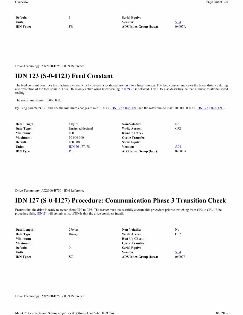
IDN 123 (S-0-0123) Feed Constant The feed constant describes the machine element which converts a rotational motion into a linear motion. The feed constant indicates the linear distance during one revolution of the feed spindle. This IDN is only active when linear scaling in IDN 76 is selected. This IDN also describes the feed at linear rotational speed scaling.
The maximum is now 10 000 000.
By using parameter 121 and 122 the minimum changes to min: 100 x ( IDN 122 / IDN 121 )and the maximum to max: 100 000 000 x ( IDN 122 / IDN 121 )
IDN 127 (S-0-0127) Procedure: Communication Phase 3 Transition Check Ensures that the drive is ready to switch from CP2 to CP3. The master must successfully execute this procedure prior to switching from CP2 to CP3. If the procedure fails, IDN 21 will contain a list of IDNs that the drive considers invalid.
Default: 1 Serial Equiv:Units: Version: 5.04IDN Type: FB ADS Index Group (hex.): 0x007A
Drive Technology: AX2000-B750 - IDN Reference
Data Length: 4 bytes Non-Volatile: NoData Type: Unsigned decimal Write Access: CP2Minimum: 100 Run-Up Check:Maximum: 10 000 000 Cyclic Transfer:Default: 100 000 Serial Equiv:Units: IDN 76 , 77, 78 Version: 5.04IDN Type: PS ADS Index Group (hex.): 0x007B
Drive Technology: AX2000-B750 - IDN Reference
Data Length: 2 bytes Non-Volatile: NoData Type: Binary Write Access: CP2Minimum: Run-Up Check:Maximum: Cyclic Transfer:Default: 0 Serial Equiv:Units: Version: 5.04IDN Type: SC ADS Index Group (hex.): 0x007F
Drive Technology: AX2000-B750 - IDN Reference
Page 280 of 390Overview
8/7/2006file://C:\Documents and Settings\tope\Local Settings\Temp\~hhD469.htm

IDN 128 (S-0-0128) Procedure: Communication Phase 4 Transition Check Ensures that the drive is ready to switch from CP3 to CP4. The master must successfully execute this procedure prior to switching from CP3 to CP4. If the procedure fails, IDN 22 will contain a list of IDNs that the drive considers invalid.
If any of the macros have been changed in CP2 or CP3, the drive will re-compile the macro program and perform a warm start, which may take up to 3 minutes. During the warm start, the LED on the front panel of the drive add with the three dots will flashing. During the warmstart IDN 182 Bit 1 is set, it will cleared after the warmstart. Alternatively, the serial interface may be used to save all values and reset the drive before the CP4 transition check procedure is executed. (For an explanation of the macros, please consult our applications department.)
IDN 129 (S-0-0129) Manufacturer Class 1 Diagnostic (MC1D) Lists the status of the latched manufacturer defined drive faults. When a manufacturer defined fault occurs, the drive decelerates to a stop and disables. The C1D status bit (AT status bit 13) is set, IDN 11 bit 15 is set, and the corresponding manufacturer-defined fault bit is set within IDN 129. All manufacturer defined faults are latched within IDN 129 and are reset through the “Reset Class 1 Diagnostic” procedure ( IDN 99 ). IDN 99 performs a coldstart automatically when required. Those faults which require a coldstart are noted in the table below. The error messages which appear on the front panel of the drive are also shown below.
Definition:
Data Length: 2 bytes Non-Volatile: NoData Type: Binary Write Access: CP3Minimum: Run-Up Check:Maximum: Cyclic Transfer:Default: 0 Serial Equiv:Units: Version: 5.04IDN Type: SC ADS Index Group (hex.): 0x0080
Drive Technology: AX2000-B750 - IDN Reference
Data Length: 2 bytes Non-Volatile: NoData Type: Binary Write Access: Read-onlyMinimum: Run-Up Check:Maximum: Cyclic Transfer:Default: 0 Serial Equiv: ERRCODEUnits: Version: 5.04IDN Type: MT:FS ADS Index Group (hex.): 0x0081
Bit Description Coldstart LED ErrorLSB 0 Reserved1 Non-volatile memory check-sum fault yes F09, F102 Warning fault (actual warning is mask
to a fault)no F24
3 Motor brake fault yes F114 Supply voltage not present no F165 A/D converter fault yes F176 Regeneration fault yes F187 System fault yes F328 Reserved9 Motor over speed fault no F0810 Excessive position command
differenceNo F28
Page 281 of 390Overview
8/7/2006file://C:\Documents and Settings\tope\Local Settings\Temp\~hhD469.htm

IDN 130 (S-0-0130) Probe 1 Positive Edge Value The “Probing” procedure ( IDN 170 ) is used to capture the motor position ( IDN 51 ) when a digital input changes. IDN 130 will contain the captured position when the “Probe Control Parameter” ( IDN 169 , bit 0) is configured for probe 1 to capture the position on the rising edge of the digital input.
IDN 131 (S-0-0131) Probe 1 Negative Edge Value The “Probing” procedure ( IDN 170 ) is used to capture the motor position ( IDN 51 ) when a digital input changes. IDN 131 will contains the captured position when the “Probe Control Parameter” ( IDN 169 , bit 1) is configured for probe 1 to capture the position on the falling edge of the digital input.
IDN 132 (S-0-0132) Probe 2 Positive Edge Value The “Probing” procedure ( IDN 170 ) is used to capture the external position ( IDN 53 ) when a digital input changes. IDN 132 will contains the captured
11 Non-permissible software-enable (no hardware-enable; no SERCOS control)
No F29
12 – 15 Reserved
Drive Technology: AX2000-B750 - IDN Reference
Data Length: 4 bytes Non-Volatile: NoData Type: Signed decimal Write Access: Read-onlyMinimum: Run-Up Check:Maximum: Cyclic Transfer: ATDefault: Serial Equiv: LATCH32Units: IDN 76 , 77, 78, 79 Version: 5.04IDN Type: PS ADS Index Group (hex.): 0x0082
Drive Technology: AX2000-B750 - IDN Reference
Data Length: 4 bytes Non-Volatile: NoData Type: Signed decimal Write Access: Read-onlyMinimum: Run-Up Check:Maximum: Cyclic Transfer: ATDefault: Serial Equiv: LATCH32NUnits: IDN 76 , 77, 78, 79 Version: 5.04IDN Type: PS ADS Index Group (hex.): 0x0083
Drive Technology: AX2000-B750 - IDN Reference
Page 282 of 390Overview
8/7/2006file://C:\Documents and Settings\tope\Local Settings\Temp\~hhD469.htm

position when the “Probe Control Parameter” ( IDN 169 , bit 2) is configured for probe 2 to capture the position on the rising edge of the digital input.
IDN 133 (S-0-0133) Probe 2 Negative Edge Value The “Probing” procedure ( IDN 170 ) is used to capture the external position ( IDN 53 ) when a digital input changes. IDN 133 will contains the captured position when the “Probe Control Parameter” ( IDN 169 , bit 3) is configured for probe 2 to capture the position on the falling edge of the digital input.
IDN 134 (S-0-0134) Master Control Word The drive’s control word within the MDT is stored within IDN 134 as a diagnostic aid.
Data Length: 4 bytes Non-Volatile: NoData Type: Signed decimal Write Access: Read-onlyMinimum: Run-Up Check:Maximum: Cyclic Transfer: ATDefault: Serial Equiv: LATCHX32Units: IDN 76 , 79 Version: 5.04IDN Type: PS ADS Index Group (hex.): 0x0084
Drive Technology: AX2000-B750 - IDN Reference
Data Length: 4 bytes Non-Volatile: NoData Type: Signed decimal Write Access: Read-onlyMinimum: Run-Up Check:Maximum: Cyclic Transfer: ATDefault: Serial Equiv: LATCHX32NUnits: IDN 76 , 79 Version: 5.04IDN Type: PS ADS Index Group (hex.): 0x0085
Drive Technology: AX2000-B750 - IDN Reference
Data Length: 2 bytes Non-Volatile: NoData Type: Binary Write Access: Read-onlyMinimum: Run-Up Check:Maximum: Cyclic Transfer:Default: Serial Equiv:Units: Version: 5.04IDN Type: SC ADS Index Group (hex.): 0x0086
Page 283 of 390Overview
8/7/2006file://C:\Documents and Settings\tope\Local Settings\Temp\~hhD469.htm

IDN 135 (S-0-0135) Drive Status Word The AT telegram status word is stored within IDN 135 as a diagnostic aid.
IDN 136 (S-0-0136) Positive Acceleration Limit Value Defines the drive's maximum positive acceleration when the drive is in velocity mode. The positive acceleration limit is defined as the number of milliseconds to reach the maximum velocity limit from standstill ( IDN 38 , 39, 91).
IDN 137 (S-0-0137) Negative Acceleration Limit Value Defines the drive's maximum deceleration (negative acceleration) when the drive is in velocity mode. The drive alternatively uses the quick deceleration limit ( IDN 3022 under the following conditions: position limits are encountered, a fault has occurred, or the master has requested an active disable (MDT control word, bit 15). The quick deceleration limit ( IDN 3022 is always used by the drive when those conditions occur. The negative acceleration limit is defined as the number of milliseconds to go from the maximum velocity limit to standstill ( IDN 38 , 39, 91).
Drive Technology: AX2000-B750 - IDN Reference
Data Length: 2 bytes Non-Volatile: NoData Type: Binary Write Access: Read-onlyMinimum: Run-Up Check:Maximum: Cyclic Transfer:Default: Serial Equiv:Units: Version: 5.04IDN Type: SC ADS Index Group (hex.): 0x0087
Drive Technology: AX2000-B750 - IDN Reference
Data Length: 4 bytes Non-Volatile: YesData Type: Signed decimal Write Access: CP2, CP3, CP4Minimum: 1 Run-Up Check:Maximum: 32767 Cyclic Transfer:Default: 10 Serial Equiv: ACCUnits: IDN 160 , 161, 162 Version: 5.04IDN Type: AD ADS Index Group (hex.): 0x0088
Drive Technology: AX2000-B750 - IDN Reference
Data Length: 4 bytes Non-Volatile: YesData Type: Signed decimal Write Access: CP2, CP3, CP4Minimum: -32767 Run-Up Check:Maximum: -1 Cyclic Transfer:Default: -10 Serial Equiv: DEC
Page 284 of 390Overview
8/7/2006file://C:\Documents and Settings\tope\Local Settings\Temp\~hhD469.htm

IDN 140 (S-0-0140)
IDN 141 (S-0-0141) Motor Type The master may use this IDN to read or write the motor type text describing. The master can select the motor that is used from the motor database of the drive.
IDN 142 (S-0-0142) Application Type The master may use this IDN to store text describing the drive’s application.
Units: IDN 160 , 161, 162 Version: 5.04IDN Type: AD ADS Index Group (hex.): 0x0089
Drive Technology: AX2000-B750 - IDN Reference
Data Length: 1 byte elements, variable length array Non-Volatile: YesData Type: Text Write Access: Read-onlyMinimum: Run-Up Check:Maximum: Cyclic Transfer:Default: Serial Equiv: VER *Units: Version: 5.04IDN Type: GE ADS Index Group (hex.): 0x008C
Drive Technology: AX2000-B750 - IDN Reference
Data Length: 1 byte elements, variable length array Non-Volatile: YesData Type: Text Write Access: CP4Minimum: Run-Up Check:Maximum: Cyclic Transfer:Default: “NN” Serial Equiv: MNAMEUnits: Version: 5.04IDN Type: GE ADS Index Group (hex.): 0x008D
Drive Technology: AX2000-B750 - IDN Reference
Data Length: 1 byte elements, variable length array Non-Volatile: YesData Type: Text Write Access: CP2, CP3, CP4
Page 285 of 390Overview
8/7/2006file://C:\Documents and Settings\tope\Local Settings\Temp\~hhD469.htm

IDN 143 (S-0-0143) SYSTEM Interface Version Contains the version number of the SERCOS specification. The drive conforms this version of the specification.
IDN 147 (S-0-0147) Homing Parameter The “Drive Controlled Homing” procedure ( IDN 148 ) is configured through IDN 41 , IDN 42 and IDN 147. Only the bits 0, 5 and 6 are supported, if the home switch is evaluated to the drive bit 1 must set to 0 and bit 2 must set 1. All other reserved bits must be set as indicated by the bold type within the following table. To the different homing types refer also to IDN 3027 If the position control is set on the external encoder , bit 3 must be set to 1.
Definition:
Minimum: Run-Up Check:Maximum: Cyclic Transfer:Default: “DRIVE0” Serial Equiv: ALIASUnits: Version: 5.04IDN Type: GE ADS Index Group (hex.): 0x008E
Drive Technology: AX2000-B750 - IDN Reference
Data Length: 1 byte elements, variable length array Non-Volatile: YesData Type: Text Write Access: Read-onlyMinimum: Run-Up Check:Maximum: Cyclic Transfer:Default: “V01.02” Serial Equiv:Units: Version: 5.04IDN Type: SC ADS Index Group (hex.): 0x008F
Drive Technology: AX2000-B750 - IDN Reference
Data Length: 2 bytes Non-Volatile: YesData Type: Binary Write Access: CP2, CP3, CP4Minimum: Run-Up Check:Maximum: Cyclic Transfer:Default: 0085H Serial Equiv:Units: Version: 5.04IDN Type: PS ADS Index Group (hex.): 0x0093
Bit Description SettingLSB 0 Homing direction 0 = CW
1 = CCW 1 Home switch polarity 1 = Active on falling edge 2 Home switch location 0 = Master
Page 286 of 390Overview
8/7/2006file://C:\Documents and Settings\tope\Local Settings\Temp\~hhD469.htm

IDN 148 (S-0-0148) Procedure: Drive Controlled Homing The drive automatically enters an internal position mode and homes the drive. Homing is configured through the “Homing Velocity” ( IDN 41 ), “Homing Acceleration” ( IDN 42 ) and the “Homing Parameter” ( IDN 147 ). The homing procedure should fail under the following conditions:
1) The drive is disabled, or the master clears any of the enable bits (MDT bits 13-15) during drive-controlled homing.
2) The “Probing” procedure ( IDN 170 ) is active.
3) The home switch is located on the drive ( IDN 147 , bit 2 is set) and will be evaluated during homing ( IDN 147 , bit 5 is clear) and a configurable input has not been configured as a home switch input.
4) A fault occurs during drive controlled homing.
The home switch is located on the master ( IDN 147 , bit 2 is clear) and will be evaluated during homing ( IDN 147 , bit 5 is clear) and the “Homing Enable” signal ( IDN 407 ) has not been configured as a real time control bit.
The master should not cancel the drive controlled homing procedure until it has aligned its position command with the drive’s present position command. The master may abort drive controlled homing by first stopping the drive through the start/stop bit (MDT control bit 13), aligning its position command with the drive and then canceling the procedure.
IDN 159 (S-0-0159) Monitoring Window The monitoring window defines the maximum position error. When the absolute distance between the active position command and active position feedback exceeds the monitoring window, an “excessive position deviation” fault is generated ( IDN 11 , bit 11).
4 Reserved: Home enable evaluation Set to 0 6 Marker pulse evaluation 1 = Not evaluated 7 Reserved: Stop condition 1 = On home position ( IDN 52 , 54) 8 – 15 Reserved. Set to 0
Drive Technology: AX2000-B750 - IDN Reference
Data Length: 2 bytes Non-Volatile: NoData Type: Binary Write Access: CP4Minimum: Run-Up Check:Maximum: Cyclic Transfer:Default: 0 Serial Equiv:Units: Version: 5.04IDN Type: PS ADS Index Group (hex.): 0x0094
Drive Technology: AX2000-B750 - IDN Reference
Data Length: 4 bytes Non-Volatile: YesData Type: Signed decimal Write Access: CP2, CP3, CP4Minimum: 0 Run-Up Check:Maximum: 7FFF FFFFH Cyclic Transfer:Default: 262144 Serial Equiv: PEMAX
Page 287 of 390Overview
8/7/2006file://C:\Documents and Settings\tope\Local Settings\Temp\~hhD469.htm

IDN 160 (S-0-0160) Acceleration Data Scaling Type Defines the scaling options for all acceleration data. The scaling types which are supported are indicated in bold face type. The rotational parameter scaling setting (IDN 160 = 000A H), could not save in the EEPROM (refer to IDN 161 , 162). For the no scaling option, all acceleration data are scaled in ms, to reach the bipolar velocity limit. A new value will not become active until the parameter is saved to non-volatile memory and a coldstart or warmstart ( IDN 128procedure is initiated
Definition:
IDN 161 (S-0-0161) Acceleration Data Scaling Factor
Units: IDN 76 , 77, 78, 79 Version: 5.04IDN Type: PS:FS ADS Index Group (hex.): 0x009F
Drive Technology: AX2000-B750 - IDN Reference
Data Length: 2 bytes Non-Volatile: YesData Type: Binary Write Access: CP2, CP3Minimum: 0 Run-Up Check:Maximum: 000AH Cyclic Transfer:Default: 0 Serial Equiv: ACCUNITUnits: Version: 5.04IDN Type: AD ADS Index Group (hex.): 0x00A0
Bit Description2 - 0 Scaling Method 000=No scaling
001=reserved: Linear Scaling
010=Rotational Scaling 3 Standard Scaling Type 0=Preferred Scaling
1=Parameter Scaling 4 Reserved: Units for Linear Scaling 0=Meters (m)
1=Inches (in) 4 Units for Rotational Scaling 0=Radian
1=Reserved 5 Time Units 0=Seconds (s)
1=Reserved 6 Data Reference 0=At the Motor Shaft
1=Reserved: At the Load 15-7 Reserved
Drive Technology: AX2000-B750 - IDN Reference
Page 288 of 390Overview
8/7/2006file://C:\Documents and Settings\tope\Local Settings\Temp\~hhD469.htm

This parameter defines the scaling factor for all acceleration data in the drive, when rotational parameter scaling in IDN 160 is selected (Refer to IDN 160 ,162).
IDN 162 (S-0-0162) Acceleration Data Scaling Exponent This parameter defines the scaling exponent for all acceleration data in the drive, when rotational parameter scaling in IDN 160 is selected (Refer to IDN 160 ,161).
IDN 169 (S-0-0169) Probe Control Parameter The probe control parameter defines the input signal edge that will result in a position capture during the “Probing” procedure ( IDN 170 ). Each probe may be used to capture positions on both probe signal edges, but the probe edges must be separated by at least 2 milliseconds. The table below describe the fixed settings if only the digital input 2 is used for the latched function, for the other settings please refer also to IDN 3018
Data Length: 2 bytes Non-Volatile: YesData Type: Unsigned decimal Write Access: Read-onlyMinimum: Run-Up Check:Maximum: Cyclic Transfer:Default: 1 Serial Equiv:Units: Version: 5.04IDN Type: PS ADS Index Group (hex.): 0x00A1
Drive Technology: AX2000-B750 - IDN Reference
Data Length: 2 bytes Non-Volatile: YesData Type: Signed decimal Write Access: CP2, CP3Minimum: -3 Run-Up Check:Maximum: 0 Cyclic Transfer:Default: -3 Serial Equiv:Units: Version: 5.04IDN Type: PS ADS Index Group (hex.): 0x00A2
Drive Technology: AX2000-B750 - IDN Reference
Data Length: 2 bytes Non-Volatile: NoData Type: Binary Write Access: CP2, CP3, CP4Minimum: 0 Run-Up Check:Maximum: 15 Cyclic Transfer:Default: 0 Serial Equiv:Units: Version: 5.04IDN Type: PS ADS Index Group (hex.): 0x00A9
Page 289 of 390Overview
8/7/2006file://C:\Documents and Settings\tope\Local Settings\Temp\~hhD469.htm

Definition:
IDN 170 (S-0-0170) Procedure: Probing Probing is used to capture position data when a digital input changes. Each probe may trigger a position capture using both edges (rising and/or falling) of the digital input signal, as long as the edges are separated by at least 2 milliseconds. The “Probe Control Parameter” ( IDN 169 ) is used to configure the digital input edges that will trigger a position capture. Once the probe procedure is started by the master (set IDN 170 to 3), it will continue indefinitely until either the master cancels the probing procedure or a probing error occurs. The probing procedure will fail under the following conditions:
1) The “Homing” procedure ( IDN 148 ) is active.
2) A digital input has not been configured as a position capture input ( IDN 3001 .
During the probing procedure, the master arms the probe trigger by setting a “Probe Enable” signal ( IDN 405 or IDN 406 ). After the probe trigger has been armed, the next rising and/or falling edge(s) (as specified in IDN 169 ) on the probe inputs ( IDN 401 or IDN 402 ) will latch the motor position and cause the corresponding “Probe Position Latch Status” ( IDN 179 ) bits to set. Any further changes in the probe input are ignored until the master re-arms the probe trigger by clearing and setting the probe enable signal. The master may read captured positions through the “Probe Positive Edge Value” ( IDN 130 and IDN 132 ) and the “Probe Negative Edge Value” ( IDN 131 and IDN 133 ).
The drive supports two physical probe input that must be pre-configured through IDN 3001 and IDN 3000 before starting the probe procedure. It will be select with IDN 3018 Probe 1 with the physical input 2 and Probe 2 with the physical input 1 and all combination for the feedback types for both probes.
Although it is possible to use only one physical probe input (digital input 2) with the two logical probes that are operated independently. Logical probe 1 supports capturing the motor feedback while logical probe 2 supports capturing the external feedback.
Bit Description SettingLSB 0 Probe 1 – Capture motor position on positive edge 0 = Inactive.
1 = Active. 1 Probe 1 – Capture motor position on negative edge 0 = Inactive.
1 = Active. 2 Probe 2 – Capture external position on positive
edge0 = Inactive.
1 = Active. 3 Probe 2 – Capture external position on negative
edge0 = Inactive.
1 = Active. 4 - 15 Reserved. Set to 0.
Drive Technology: AX2000-B750 - IDN Reference
Data Length: 2 bytes Non-Volatile: NoData Type: Binary Write Access: CP4Minimum: Run-Up Check:Maximum: Cyclic Transfer:Default: 0 Serial Equiv:Units: Version: 5.04IDN Type: PS ADS Index Group (hex.): 0x00AA
Drive Technology: AX2000-B750 - IDN Reference
Page 290 of 390Overview
8/7/2006file://C:\Documents and Settings\tope\Local Settings\Temp\~hhD469.htm
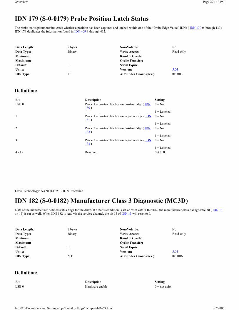
IDN 179 (S-0-0179) Probe Position Latch Status The probe status parameter indicates whether a position has been captured and latched within one of the “Probe Edge Value” IDNs ( IDN 130 0 through 133). IDN 179 duplicates the information found in IDN 409 9 through 412.
Definition:
IDN 182 (S-0-0182) Manufacturer Class 3 Diagnostic (MC3D) Lists of the manufacturer defined status flags for the drive. If a status condition is set or reset within IDN182, the manufacturer class 3 diagnostic bit ( IDN 13bit 15) is set as well. When IDN 182 is read via the service channel, the bit 15 of IDN 13 will reset to 0.
Definition:
Data Length: 2 bytes Non-Volatile: NoData Type: Binary Write Access: Read-onlyMinimum: Run-Up Check:Maximum: Cyclic Transfer:Default: 0 Serial Equiv:Units: Version: 5.04IDN Type: PS ADS Index Group (hex.): 0x00B3
Bit Description SettingLSB 0 Probe 1 – Position latched on positive edge ( IDN
130 )0 = No.
1 = Latched. 1 Probe 1 – Position latched on negative edge ( IDN
131 )0 = No.
1 = Latched. 2 Probe 2 – Position latched on positive edge ( IDN
132 )0 = No.
1 = Latched. 3 Probe 2 – Position latched on negative edge ( IDN
133 )0 = No.
1 = Latched. 4 - 15 Reserved. Set to 0.
Drive Technology: AX2000-B750 - IDN Reference
Data Length: 2 bytes Non-Volatile: NoData Type: Binary Write Access: Read-onlyMinimum: Run-Up Check:Maximum: Cyclic Transfer:Default: 0 Serial Equiv:Units: Version: 5.04IDN Type: MT ADS Index Group (hex.): 0x00B6
Bit Description SettingLSB 0 Hardware enable 0 = not exist
Page 291 of 390Overview
8/7/2006file://C:\Documents and Settings\tope\Local Settings\Temp\~hhD469.htm

IDN 185 (S-0-0185) Maximum Length of AT Configurable Data Defines the maximum length, in bytes, of the AT's cyclic data field. The master may use this IDN to determine how many IDNs may be placed within the application telegram (refer to IDN 15 ).
IDN 186 (S-0-0186) Maximum Length of MDT Configurable Data Defines the maximum length, in bytes, of the MDT's cyclic data field. The master may use this IDN to determine how many IDNs may be placed within an application telegram (refer to IDN 15 ).
1 = exist 1 Warmstart ( IDN 128 ) 0 = not running
1 = still running 2-15 Reserved
Drive Technology: AX2000-B750 - IDN Reference
Data Length: 2 bytes Non-Volatile: YesData Type: Unsigned decimal Write Access: Read-onlyMinimum: Run-Up Check:Maximum: Cyclic Transfer:Default: 24 Serial Equiv:Units: Bytes Version: 5.04IDN Type: SC ADS Index Group (hex.): 0x00B9
Drive Technology: AX2000-B750 - IDN Reference
Data Length: 2 bytes Non-Volatile: YesData Type: Unsigned decimal Write Access: Read-onlyMinimum: Run-Up Check:Maximum: Cyclic Transfer:Default: 12 Serial Equiv:Units: Bytes Version: 5.04IDN Type: SC ADS Index Group (hex.): 0x00BA
Drive Technology: AX2000-B750 - IDN Reference
Page 292 of 390Overview
8/7/2006file://C:\Documents and Settings\tope\Local Settings\Temp\~hhD469.htm

IDN 187 (S-0-0187) List of AT Configurable Data IDNs Lists all the IDNs that may be transferred as AT cyclic data. The master may use this IDN to determine the IDNs that may be placed within an application telegram (refer to IDN 15 ). The following IDNs may be assigned as AT cyclic data:
Definition:
IDN 188 (S-0-0188) List of MDT Configurable Data IDNs Lists all the IDNs that may be transferred as MDT cyclic data. The master may use this IDN to determine the IDNs that may be placed within an application telegram (refer to IDN 15 ). The following IDNs may be assigned as MDT cyclic data:
Data Length: 2 byte elements, variable length array Non-Volatile: YesData Type: IDN Write Access: Read-onlyMinimum: Run-Up Check:Maximum: Cyclic Transfer:Default: Serial Equiv:Units: Version: 5.04IDN Type: SC ADS Index Group (hex.): 0x00BB
IDN Description40 Velocity Feedback Value51 Position Feedback Value 1 (motor)53 Position Feedback Value 2 (external)59 Position Switch Flag Parameter84 Torque Feedback Value130 Probe 1 Positive Edge Value131 Probe 1 Negative Edge Value132 Probe 2 Positive Edge Value133 Probe 2 Negative Edge Value189 Following DistanceIDN 3012 Difference Probe Edge Value 1IDN 3013 Difference Probe Edge Value 2IDN 3030 Configurable I/O: Digital Input 1 StatusIDN 3031 Configurable I/O: Digital Input 2 StatusIDN 3032 Configurable I/O: Digital Input 3 StatusIDN 3033 Configurable I/O: Digital Input 4 StatusIDN 3034 Analog Input 1 ValueIDN 3035 Analog Input 2 Value
Drive Technology: AX2000-B750 - IDN Reference
Data Length: 2 byte elements, variable length array Non-Volatile: YesData Type: IDN Write Access: Read-onlyMinimum: Run-Up Check:Maximum: Cyclic Transfer:Default: Serial Equiv:Units: Version: 5.04IDN Type: SC ADS Index Group (hex.): 0x00BC
Page 293 of 390Overview
8/7/2006file://C:\Documents and Settings\tope\Local Settings\Temp\~hhD469.htm

Definition:
IDN 189 (S-0-0189) Following Distance The distance between the position command value and the appropriate position feedback value (1 or 2). The drive calculates this value by subtracting the position feedback value (1 or 2) from the position command value.
IDN 192 (S-0-0192) IDN List of Back-up Operation Data A list of all IDNs which are essential for drive operation. The master may use this list to back-up the drive parameters. If the drive is replaced, the IDNs within this list may be reloaded into the replacement drive using the order defined within IDN 288 and IDN 289 or direct the order of the list within this IDN.
IDN Description36 Velocity Command Value47 Position Command Value60 Position Switch Point 161 Position Switch Point 280 Torque Command ValueIDN 3036 Configurable I/O: Digital Output 1 Control/StatusIDN 3037 Configurable I/O: Digital Output 2 Control/Status
Drive Technology: AX2000-B750 - IDN Reference
Data Length: 4 bytes Non-Volatile: NoData Type: Signed decimal Write Access: Read-onlyMinimum: Run-Up Check:Maximum: Cyclic Transfer: ATDefault: Serial Equiv: PEUnits: IDN 76 , 77, 78, 79 Version: 5.04IDN Type: PS ADS Index Group (hex.): 0x00BD
Drive Technology: AX2000-B750 - IDN Reference
Data Length: 2 byte elements, variable length array Non-Volatile: YesData Type: IDN Write Access: Read-onlyMinimum: Run-Up Check:Maximum: Cyclic Transfer:Default: Serial Equiv:Units: Version: 5.04IDN Type: GE ADS Index Group (hex.): 0x00C0
Page 294 of 390Overview
8/7/2006file://C:\Documents and Settings\tope\Local Settings\Temp\~hhD469.htm

IDN 196 (S-0-0196) Motor Rated Current The motor's rated current. If the motor rated current is less than that of the amplifier, the amplifier is automatically limited to the level of the motor rated current.
IDN 203 (S-0-0203) Amplifier Shutdown Temperature When the amplifier temperature ( heat sink temperature) exceed the value of the amplifier shutdown temperature, the drive sets the fault bit for amplifier over temperature fault in C1D ( IDN 11 bit 1).
IDN 205 (S-0-0205) Cooling Error Shutdown Temperature When the temperature inside the drive housing exceed the value of the cooling error shutdown temperature, the drive sets the fault bit for cooling system fault in C1D ( IDN 11 bit 3).
Drive Technology: AX2000-B750 - IDN Reference
Data Length: 4 bytes Non-Volatile: YesData Type: Unsigned decimal Write Access: CP2, CP3Minimum: 0.1 * IDN 112 Run-Up Check:Maximum: 2 * IDN 112 Cyclic Transfer:Default: IDN 112 Serial Equiv: MICONT * 1000Units: MA Version: 5.04IDN Type: MR ADS Index Group (hex.): 0x00C4
Drive Technology: AX2000-B750 - IDN Reference
Data Length: 2 bytes Non-Volatile: YesData Type: Unsigned decimal Write Access: CP2, CP3, CP4Minimum: 200 Run-Up Check:Maximum: 850 Cyclic Transfer:Default: 800 Serial Equiv: MAXTEMPH ( 10Units: IDN 208 Version: 5.04IDN Type: VE ADS Index Group (hex.): 0x00CB
Drive Technology: AX2000-B750 - IDN Reference
Data Length: 2 bytes Non-Volatile: YesData Type: Unsigned decimal Write Access: CP2, CP3, CP4Minimum: 100 Run-Up Check:Maximum: 800 Cyclic Transfer:Default: 700 Serial Equiv: MAXTEMPE ( 10
Page 295 of 390Overview
8/7/2006file://C:\Documents and Settings\tope\Local Settings\Temp\~hhD469.htm

IDN 208 (S-0-0208) Temperature Data Scaling Type Defines the scaling options for all temperature data. The scaling types which are supported are indicated in bold-face type.
Definition:
IDN 257 (S-0-0257) Multiplication Factor 2 The multiplication factor 2 defines the drive internal multiplication of an rotary encoder as an external feedback for the position feedback value 2 ( IDN 53 ). If the resolution of the rotational feedback 2 ( IDN 117 ) is not a result of 2x, the drive may use an additional scaling for IDN 53 . If the master write IDN 117 the drive calculate automatic the “Multiplication factor 2” (IDN 257), for the external feedback, and an additional scaling factor if necessary, to scale the external rotary encoder to the rotational position resolution set within IDN 79 (refer to IDN 53 , 79 and 117). The drive also do the automatic calculation for position control with external feedback.
Units: IDN 208 Version: 5.04IDN Type: VE ADS Index Group (hex.): 0x00CD
Drive Technology: AX2000-B750 - IDN Reference
Data Length: 2 bytes Non-Volatile: YesData Type: Binary Write Access: Read-onlyMinimum: Run-Up Check:Maximum: Cyclic Transfer:Default: 0000H Serial Equiv:Units: Version: 5.04IDN Type: VE ADS Index Group (hex.): 0x00D0
Bit Description0 Scaling Method 0 = 0,1 °C
1=Reserved: 0,1 F 15-1 Reserved 15-1
Drive Technology: AX2000-B750 - IDN Reference
Data Length: 4 bytes Non-Volatile: YesData Type: Unsigned decimal Write Access: CP2, CP3Minimum: Run-Up Check:Maximum: Cyclic Transfer:Default: 256 Serial Equiv: EXTMULUnits: Version: 5.04IDN Type: FB ADS Index Group (hex.): 0x0101
Page 296 of 390Overview
8/7/2006file://C:\Documents and Settings\tope\Local Settings\Temp\~hhD469.htm

IDN 262 (S-0-0262) Procedure: Load Default Values This procedure loads the manufacturer’s default parameters into volatile memory. The parameters stored in non-volatile memory remain unchanged. The default parameters allow the drive to operate without problems, but the operation is not necessarily optimized.
This procedure will normally modify the macro program, and the drive will re-compile the macro program and perform a warm start in the CP4 transition check, which may take up to 3 minutes. During the warm start, the LED on the front panel of the drive add with the three dots will flashing. During the warmstart IDN 182 Bit 1 is set, it will cleared after the warmstart. Alternatively, the serial interface may be used to save all values and reset the drive before the CP4 transition check procedure is executed. (For an explanation of the macros, please consult our applications department.)
IDN 264 (S-0-0264) Procedure: Back-up Working Memory This command saves all data essential for drive operation from the active memory to the non-volatile memory. IDN 192 defines which data is essential for drive operation. Previously saved data is overwritten.
IDN 271 (S-0-0271) Drive ID The master may store a unique drive identification number within this IDN. The identification number is saved to non-volatile memory when the “Back-up Working Memory” procedure ( IDN 264 ) is executed. The identification number is reset to zero when the “Load Default Values” procedure ( IDN 262 ) is executed.
Drive Technology: AX2000-B750 - IDN Reference
Data Length: 2 bytes Non-Volatile: NoData Type: Binary Write Access: CP2, CP3Minimum: Run-Up Check:Maximum: Cyclic Transfer:Default: 0 Serial Equiv: RSTVARUnits: Version: 5.04IDN Type: GE ADS Index Group (hex.): 0x0106
Drive Technology: AX2000-B750 - IDN Reference
Data Length: 2 bytes Non-Volatile: NoData Type: Binary Write Access: CP2, CP3, CP4Minimum: Run-Up Check:Maximum: Cyclic Transfer:Default: 0 Serial Equiv: SAVEUnits: Version: 5.04IDN Type: GE ADS Index Group (hex.): 0x0108
Drive Technology: AX2000-B750 - IDN Reference
Page 297 of 390Overview
8/7/2006file://C:\Documents and Settings\tope\Local Settings\Temp\~hhD469.htm

IDN 288 (S-0-0288) IDN List of Data Programmable in CP2 A list of all IDNs that may be written by the master in CP2. The IDNs are listed in the order that the master should write them to avoid data dependency problems. Data dependency problems may arise, for example, when the range of one IDN depends upon an IDN that has not yet been written.
IDN 289 (S-0-0289) IDN List of Data Programmable in CP3 A list of all IDNs that may be written by the master in CP3. The IDNs are listed in the order that the master should write them to avoid data dependency problems. Data dependency problems may arise, for example, when the range of one IDN depends upon an IDN that has not yet been written.
Data Length: 4 bytes Non-Volatile: YesData Type: Unsigned decimal Write Access: CP2, CP3, CP4Minimum: 0 Run-Up Check:Maximum: 32 767 Cyclic Transfer:Default: 0 Serial Equiv: UIDUnits: Version: 5.04IDN Type: MT ADS Index Group (hex.): 0x010F
Drive Technology: AX2000-B750 - IDN Reference
Data Length: 2 byte elements, variable length array Non-Volatile: YesData Type: IDN Write Access: Read-onlyMinimum: Run-Up Check:Maximum: Cyclic Transfer:Default: Serial Equiv:Units: Version: 5.04IDN Type: GE ADS Index Group (hex.): 0x0120
Drive Technology: AX2000-B750 - IDN Reference
Data Length: 2 byte elements, variable length array Non-Volatile: YesData Type: IDN Write Access: Read-onlyMinimum: Run-Up Check:Maximum: Cyclic Transfer:Default: Serial Equiv:Units: Version: 5.04IDN Type: GE ADS Index Group (hex.): 0x0121
Page 298 of 390Overview
8/7/2006file://C:\Documents and Settings\tope\Local Settings\Temp\~hhD469.htm

IDN 296 (S-0-0296) Velocity Feed Forward Gain Defines a multiplier for an additive velocity command that is generated from the position profile. Velocity feed forward helps to reduce the velocity dependent following error. Velocity feed forward is added to the velocity command when the active operational mode defined by IDN 32 and/or IDN 33 has bit 3 set and is in position control mode.
IDN 298 (S-0-0298) Home Switch Distance The distance the home switch is from the “optimal” location after homing. The “optimal” location is defined as half the distance between successive marker pulses (encoder) or null points (resolvers). The home switch distance may be used to ensure that the home switch is located correctly to avoid inconsistent homing. The home switch distance is not valid until homing has completed successfully ( IDN 403 is set).
IDN 301 (S-0-0301) Allocation of Real-time Control Bit 1 Assigns a control signal IDN to the real-time control bit 1 (RTC bit 1, MDT control word bit 6). Two RTC bits are defined within the MDT control word (bits 6 and 7) and may be updated every communication cycle by the master. The following rules govern the assignment and use of RTC bit:
Only certain control signal IDNs of type binary may be assigned to the real time control allocation IDNs. The exception is IDN 0 , which indicates that the real time control bit is undefined. The following IDNs may be assigned as RTC signals: IDN 0 , IDN 405 ( IDN 3039 = 0), IDN 406 ( IDN 3039 = 0) and IDN 3038 ( IDN 3039 = 1).
A new RTC bit assignment must be valid within the drive, before the service channel busy bit is being reset. After the service channel busy bit from the drive is reset, the master can operate with the RTC bit 1 in the master control word.
Drive Technology: AX2000-B750 - IDN Reference
Data Length: 2 bytes Non-Volatile: YesData Type: Unsigned decimal Write Access: CP2, CP3, CP4Minimum: 0 Run-Up Check:Maximum: 2000 Cyclic Transfer:Default: 1000 Serial Equiv: GPFFVUnits: 0.1% Version: 5.04IDN Type: VE ADS Index Group (hex.): 0x0128
Drive Technology: AX2000-B750 - IDN Reference
Data Length: 4 bytes Non-Volatile: NoData Type: Signed decimal Write Access: Read-onlyMinimum: Run-Up Check:Maximum: Cyclic Transfer:Default: 0 Serial Equiv:Units: IDN 76 , 77, 78, 79 Version: 5.04IDN Type: PS ADS Index Group (hex.): 0x012A
Drive Technology: AX2000-B750 - IDN Reference
Page 299 of 390Overview
8/7/2006file://C:\Documents and Settings\tope\Local Settings\Temp\~hhD469.htm

IDN 303 (S-0-0303) Allocation of Real-time Control Bit 2 Assigns a control signal IDN to the real-time control bit 2 (RTC bit 2, MDT control word bit 7). Two RTC bits are defined within the MDT control word (bits 6 and 7) and may be updated every communication cycle by the master. For further information refer to IDN 301 .
IDN 304 (S-0-0304) Real-Time Status Bit 1 The value of the IDN assigned to RTS bit 1.
Data Length: 2 bytes Non-Volatile: NoData Type: IDN Write Access: CP2, CP3, CP4Minimum: Run-Up Check:Maximum: Cyclic Transfer:Default: 0 Serial Equiv:Units: Version: 5.04IDN Type: MT:SC ADS Index Group (hex.): 0x012D
Drive Technology: AX2000-B750 - IDN Reference
Data Length: 2 bytes Non-Volatile: NoData Type: IDN Write Access: CP2, CP3, CP4Minimum: Run-Up Check:Maximum: Cyclic Transfer:Default: 0 Serial Equiv:Units: Version: 5.04IDN Type: MT:SC ADS Index Group (hex.): 0x012F
Drive Technology: AX2000-B750 - IDN Reference
Data Length: 2 bytes Non-Volatile: NoData Type: Binary Write Access: Read-onlyMinimum: Run-Up Check:Maximum: Cyclic Transfer:Default: Serial Equiv:Units: Version: 5.04IDN Type: MT:SC ADS Index Group (hex.): 0x0130
Drive Technology: AX2000-B750 - IDN Reference
Page 300 of 390Overview
8/7/2006file://C:\Documents and Settings\tope\Local Settings\Temp\~hhD469.htm

IDN 305 (S-0-0305) Allocation of Real-time Status Bit 1 The IDN of a real-time status signal that appears in real-time status bit 1 (AT status word, bit 6). Two real time status bits are defined within the AT status word (bits 6 and 7) and are continuously updated by the drive during CP4. The following rules govern the assignment and use of a real time status bit (i.e. writing IDN 305 or 307):
Only status signal IDNs of type binary may be assigned to the real time status allocation IDNs. The exception is IDN 0 , which indicates that the real time status bit is undefined. The following IDNs may be assigned as RTS signals: IDN 0 , IDN 336 , IDN 400 , IDN 403 , IDN 409 , IDN 410 , IDN 411 and IDN 412 .
The master should no longer evaluate a previous real time status assignment after transmitting a write request for element 7 of a real time status bit allocation IDN. The previously assigned real time status bit will remain valid until the service channel busy bit is set.
The master should not start evaluating a new real time status bit assignment until the service channel busy bit is reset by the drive.
IDN 306 (S-0-0306) Real-Time Status Bit 2 The value of the IDN assigned to RTS bit 2.
IDN 307 (S-0-0307) Allocation of Real-time Status Bit 2 The IDN of a real-time status signal that appears in real-time status bit 2 (AT status word, bit 7). Two real time status bits are defined within the AT status word (bits 6 and 7) and are continuously updated by the drive during CP4. For further information, refer to IDN 305 .
Data Length: 2 bytes Non-Volatile: NoData Type: IDN Write Access: CP2, CP3, CP4Minimum: Run-Up Check:Maximum: Cyclic Transfer:Default: 0 Serial Equiv:Units: Version: 5.04IDN Type: MT:SC ADS Index Group (hex.): 0x0131
Drive Technology: AX2000-B750 - IDN Reference
Data Length: 2 bytes Non-Volatile: NoData Type: Binary Write Access: Read-onlyMinimum: Run-Up Check:Maximum: Cyclic Transfer:Default: Serial Equiv:Units: Version: 5.04IDN Type: MT:SC ADS Index Group (hex.): 0x0132
Drive Technology: AX2000-B750 - IDN Reference
Data Length: 2 bytes Non-Volatile: No
Page 301 of 390Overview
8/7/2006file://C:\Documents and Settings\tope\Local Settings\Temp\~hhD469.htm

IDN 323 (S-0-0323) Status “Target position outside of travel range” A warning signal IDN that is set (Bit 0 = 1) when the target position is outside of the travel range. This IDN will set if the HW- or SW-Limit Switch is active. The drive show this with flashing the warning “n10” or “n07” for outside of positive range or “n11” or “n06” outside of negative range. IDN 323 duplicates the C2D “Target position outside of travel range” warning bit ( IDN 12 , bit 13).
IDN 336 (S-0-0336) Status “In Position” A status signal IDN that is set when the difference between the position command value and the position feedback value falls within the range defined by the “Position Window” ( IDN 57 ). IDN 336 duplicates the C3D “In Position” status bit ( IDN 13 , bit 6) and may be assigned to a RTS bit (AT status word bit 6 or 7) through IDN 305 or IDN 307 .
Data Type: IDN Write Access: CP2, CP3, CP4Minimum: Run-Up Check:Maximum: Cyclic Transfer:Default: 0 Serial Equiv:Units: Version: 5.04IDN Type: MT:SC ADS Index Group (hex.): 0x0133
Drive Technology: AX2000-B750 - IDN Reference
Data Length: 2 bytes Non-Volatile: NoData Type: Binary Write Access: Read-onlyMinimum: Run-Up Check:Maximum: Cyclic Transfer:Default: Serial Equiv:
Drive Technology: AX2000-B750 - IDN Reference
Data Length: 2 bytes Non-Volatile: NoData Type: Binary Write Access: Read-onlyMinimum: Run-Up Check:Maximum: Cyclic Transfer:Default: Serial Equiv:Units: Version: 5.04IDN Type: PS ADS Index Group (hex.): 0x0150
Drive Technology: AX2000-B750 - IDN Reference
Page 302 of 390Overview
8/7/2006file://C:\Documents and Settings\tope\Local Settings\Temp\~hhD469.htm

IDN 380 (S-0-0380) DC Bus Voltage The master retrieves the drive’s DC bus voltage through this IDN.
IDN 384 (S-0-0384) Amplifier Temperature The master retrieves the amplifier temperature (heat sink temperature) from the drive through this IDN.
IDN 392 (S-0-0392) Velocity Feedback Filter Time Constant The velocity feedback is passed through a first order low pass filter before being applied to the velocity loop. The filter is useful for improving the step response and operational smoothness, particularly for very small, highly dynamic motors. If the filter’s time constant is to low, then the motor may run roughly. If the filter’s time constant is to high, then the motor’s response may be soft and unstable. The filter’s time constant may be adjusted in intervals of 100 (s.
Data Length: 2 bytes Non-Volatile: NoData Type: Unsigned decimal Write Access: Read-onlyMinimum: 0 Run-Up Check:Maximum: 900 Cyclic Transfer:Default: Serial Equiv: VBUSUnits: Volt Version: 5.04IDN Type: VE ADS Index Group (hex.): 0x017C
Drive Technology: AX2000-B750 - IDN Reference
Data Length: 2 bytes Non-Volatile: NoData Type: Unsigned decimal Write Access: Read-onlyMinimum: Run-Up Check:Maximum: Cyclic Transfer:Default: Serial Equiv: TEMPH ( 10Units: IDN 208 Version: 5.04IDN Type: VE ADS Index Group (hex.): 0x0180
Drive Technology: AX2000-B750 - IDN Reference
Data Length: 2 bytes Non-Volatile: YesData Type: Unsigned decimal Write Access: CP2, CP3, CP4Minimum: 0 Run-Up Check:Maximum: 65500 Cyclic Transfer:Default: 400 Serial Equiv: GVFBTUnits: µs Version: 5.04IDN Type: VE ADS Index Group (hex.): 0x0188
Page 303 of 390Overview
8/7/2006file://C:\Documents and Settings\tope\Local Settings\Temp\~hhD469.htm

IDN 400 (S-0-0400) Home Switch Status Contains the state of the home switch. The digital input used as home switch input is assigned through the use of digital input mode IDNs ( IDN 3000 IDN 3001 IDN 3002 or IDN 3003 . IDN 400 is useful for assigning the home switch signal to a RTS bit.
IDN 401 (S-0-0401) Probe 1 Contains the state of the probe 1 input. The digital input used as a probe is assigned through the use of IDN 3001 The drive updates the probe 1 IDN only when the probing procedure ( IDN 170 ) is active and the probe 1 enable ( IDN 405 ) is set.
IDN 402 (S-0-0402) Probe 2 Contains the state of the probe 2 input. The digital input used as a probe is assigned through the use of IDN 3001 The drive updates the probe 2 IDN only when the probing procedure ( IDN 170 ) is active and the probe 2 enable ( IDN 406 ) is set.
Drive Technology: AX2000-B750 - IDN Reference
Data Length: 2 bytes Non-Volatile: NoData Type: Binary Write Access: Read-onlyMinimum: Run-Up Check:Maximum: Cyclic Transfer:Default: Serial Equiv: IN1, IN2, IN3, IN4Units: Version: 5.04IDN Type: PS:IO ADS Index Group (hex.): 0x0190
Drive Technology: AX2000-B750 - IDN Reference
Data Length: 2 bytes Non-Volatile: NoData Type: Binary Write Access: Read-onlyMinimum: Run-Up Check:Maximum: Cyclic Transfer:Default: 0 Serial Equiv: IN2Units: Version: 5.04IDN Type: PS ADS Index Group (hex.): 0x0191
Drive Technology: AX2000-B750 - IDN Reference
Data Length: 2 bytes Non-Volatile: NoData Type: Binary Write Access: Read-only
Page 304 of 390Overview
8/7/2006file://C:\Documents and Settings\tope\Local Settings\Temp\~hhD469.htm

IDN 403 (S-0-0403) Position Feedback Status The position feedback status flag is set by the drive during homing when the position feedback is referenced to the machine zero point. The status flag is reset after power-up, and when the “Drive Controlled Homing” procedure ( IDN 148 ) is started. IDN 403 may be assigned to a RTS bit (AT status word bit 6 or 7) through IDN 305 or IDN 307 .
IDN 405 (S-0-0405) Probe 1 Enable Used to arm the position capture mechanism so that the next valid probing signal edge captures the current position into IDN 130 or 131. IDN 405 may be assigned to a RTC bit (MDT control word bit 6 or 7) through IDN 301 or IDN 303 . This IDN is write-protected while it is assigned to a RTC bit and could only reset to 0 via the SC. Refer to IDN 170 for more information.
Minimum: Run-Up Check:Maximum: Cyclic Transfer:Default: 0 Serial Equiv: IN2Units: Version: 5.04IDN Type: PS ADS Index Group (hex.): 0x0192
Drive Technology: AX2000-B750 - IDN Reference
Data Length: 2 bytes Non-Volatile: NoData Type: Binary Write Access: Read-onlyMinimum: Run-Up Check:Maximum: Cyclic Transfer:Default: 0 Serial Equiv:Units: Version: 5.04IDN Type: PS ADS Index Group (hex.): 0x0193
Drive Technology: AX2000-B750 - IDN Reference
Data Length: 2 bytes Non-Volatile: NoData Type: Binary Write Access: CP2, CP3, CP4Minimum: Run-Up Check:Maximum: Cyclic Transfer:Default: Serial Equiv:Units: Version: 5.04IDN Type: PS ADS Index Group (hex.): 0x0195
Drive Technology: AX2000-B750 - IDN Reference
Page 305 of 390Overview
8/7/2006file://C:\Documents and Settings\tope\Local Settings\Temp\~hhD469.htm

IDN 406 (S-0-0406) Probe 2 Enable Used to arm the position capture mechanism so that the next valid probing signal edge captures the current position into IDN 132 or 133. IDN 406 may be assigned to a RTC bit (MDT control word bit 6 or 7) through IDN 301 or IDN 303 . This IDN is write-protected while it is assigned to a RTC bit and could only reset to 0 via the SC. Refer to IDN 170 for more information.
IDN 409 (S-0-0409) Probe 1 Positive Edge Latched Status Indicates whether captured position data has been latched within IDN 130 after the rising edge of the probe 1 input signal ( IDN 401 ). Position data can only be latched on the positive edge of probe 1 if the “Probing” procedure ( IDN 170 ) is active and the “Probe Control Parameter” ( IDN 169 ) has been configured to use the positive edge of probe 1. Additionally, probe 1 must be armed by setting the “Probe 1 Enable” ( IDN 405 ). After arming probe 1, the next probe 1 rising edge will capture the current position and the “probe 1 positive edge latched status” will set when the captured data is available in IDN 130 . Once the latched status has been set, no more position captures will occur on the rising edges of the probe 1 input until the master re-arms probe 1 by clearing and setting the probe 1 enable. Clearing the probe 1 enable signal will reset the latch status.
IDN 409 duplicates information found in the probe status ( IDN 179 , bit 0). IDN 409 may be assigned to a RTS bit (AT status word bit 6 or 7) through IDN 305 or IDN 307 .
IDN 410 (S-0-0410) Probe 1 Negative Edge Latched Status Indicates whether captured position data has been latched within IDN 131 after the falling edge of the probe 1 input signal ( IDN 401 ). Position data can only be latched on the negative edge of probe 1 if the probing procedure ( IDN 170 ) is active and the “Probe Control Parameter” ( IDN 169 ) has been configured to use the negative edge of probe 1. Additionally, probe 1 must be armed by setting the “Probe 1 Enable” ( IDN 405 ). After arming probe 1, the next probe 1 falling edge will capture the current position and the “probe 1 negative edge latched status” will set when the captured data is available in IDN 131 . Once the latched status has been set, no more position captures will occur on the falling edges of the probe 1 input until the master re-arms probe 1 by clearing and setting the probe 1 enable. Clearing the probe 1 enable signal will reset the latch status.
IDN 410 duplicates information found in the probe status ( IDN 179 , bit 1). IDN 410 may be assigned to a RTS bit (AT status word bit 6 or 7) through IDN
Data Length: 2 bytes Non-Volatile: NoData Type: Binary Write Access: CP2, CP3, CP4Minimum: Run-Up Check:Maximum: Cyclic Transfer:Default: Serial Equiv:Units: Version: 5.04IDN Type: PS ADS Index Group (hex.): 0x0196
Drive Technology: AX2000-B750 - IDN Reference
Data Length: 2 bytes Non-Volatile: NoData Type: Binary Write Access: Read-onlyMinimum: Run-Up Check:Maximum: Cyclic Transfer:Default: 0 Serial Equiv:Units: Version: 5.04IDN Type: PS ADS Index Group (hex.): 0x0199
Drive Technology: AX2000-B750 - IDN Reference
Page 306 of 390Overview
8/7/2006file://C:\Documents and Settings\tope\Local Settings\Temp\~hhD469.htm

305 or IDN 307 .
IDN 411 (S-0-0411) Probe 2 Positive Edge Latched Status Indicates whether captured position data has been latched within IDN 132 after the rising edge of the probe 2 input signal ( IDN 402 ). Position data can only be latched on the positive edge of probe 2 if the “Probing” procedure ( IDN 170 ) is active and the “Probe Control Parameter” ( IDN 169 ) has been configured to use the positive edge of probe 2. Additionally, probe 2 must be armed by setting the “Probe 2 Enable” ( IDN 406 ). After arming probe 2, the next probe 2 rising edge will capture the current position and the “probe 2 positive edge latched status” will set when the captured data is available in IDN 132 . Once the latched status has been set, no more position captures will occur on the rising edges of the probe 2 input until the master re-arms probe 2 by clearing and setting the probe 2 enable. Clearing the probe 2 enable signal will reset the latch status.
IDN 411 duplicates information found in the probe status ( IDN 179 , bit 2). IDN 411 may be assigned to a RTS bit (AT status word bit 6 or 7) through IDN 305 or IDN 307 .
IDN 412 (S-0-0412) Probe 2 Negative Edge Latched Status Indicates whether captured position data has been latched within IDN 133 after the falling edge of the probe 2 input signal ( IDN 402 ). Position data can only be latched on the negative edge of probe 2 if the probing procedure ( IDN 170 ) is active and the “Probe Control Parameter” ( IDN 169 ) has been configured to use the negative edge of probe 2. Additionally, probe 2 must be armed by setting the “Probe 2 Enable” ( IDN 406 ). After arming probe 2, the next probe 2 falling edge will capture the current position and the “probe 2 negative edge latched status” will set when the captured data is available in IDN 133 . Once the latched status has been set, no more position captures will occur on the falling edges of the probe 2 input until the master re-arms probe 2 by clearing and setting the probe 2 enable. Clearing the probe 2 enable signal will reset the latch status.
IDN 412 duplicates information found in the probe status ( IDN 179 , bit 3). IDN 412 may be assigned to a RTS bit (AT status word bit 6 or 7) through IDN 305 or IDN 307 .
Data Length: 2 bytes Non-Volatile: NoData Type: Binary Write Access: Read-onlyMinimum: Run-Up Check:Maximum: Cyclic Transfer:Default: 0 Serial Equiv:Units: Version: 5.04IDN Type: PS ADS Index Group (hex.): 0x019A
Drive Technology: AX2000-B750 - IDN Reference
Data Length: 2 bytes Non-Volatile: NoData Type: Binary Write Access: Read-onlyMinimum: Run-Up Check:Maximum: Cyclic Transfer:Default: 0 Serial Equiv:Units: Version: 5.04IDN Type: PS ADS Index Group (hex.): 0x019B
Drive Technology: AX2000-B750 - IDN Reference
Data Length: 2 bytes Non-Volatile: No
Page 307 of 390Overview
8/7/2006file://C:\Documents and Settings\tope\Local Settings\Temp\~hhD469.htm

IDN 3000 (P-0-3000) Configurable I/O: Digital Input 1 Mode Determines the functionality of digital inputs 1 through 4. The digital inputs may be read directly through IDN 3030 through IDN 3033 . The following table describes the functions that are available. A new input mode will not be active until the parameter set is saved to non-volatile memory and a coldstart or warmstart ( IDN 128 procedure is initiated.
Definition:
Data Type: Binary Write Access: Read-onlyMinimum: Run-Up Check:Maximum: Cyclic Transfer:Default: 0 Serial Equiv:Units: Version: 5.04IDN Type: PS ADS Index Group (hex.): 0x019C
Drive Technology: AX2000-B750 - IDN Reference
Data Length: 2 bytes Non-Volatile: YesData Type: Unsigned decimal Write Access: CP2, CP3Minimum: Run-Up Check:Maximum: Cyclic Transfer:Default: Serial Equiv: InxMODE (x = 1, 2, 3, or 4).Units: Version: 5.04IDN Type: IO ADS Index Group (hex.): 0x8BB8
INx-Mode Description Active Edge Digital Input 1 2 3 4
0 Reserved –1 Reset x2 PSTOP Active low x x3 NSTOP Active low x x4 PSTOP+Intg.Off Active low x5 NSTOP+Intg.Off Active low x6 PSTOP+NSTOP Active low x7 P/NSTOP+Intg.Off Active low x8 SETP.1/SETP.2 x x x x9 MT_No_Bit x x x x10 Intg.Off Rising x x x x11 v/Torq.Contr. Active high x x x x12 Reference IDN 147 x x x x13 ROD/SSI Low/High x x x x14 FError_clear x x x x15 Start_MT Next x x x x16 Start_MT No x x x x x17 Start_ MT IO x x x x18 Ipeak2x x x x x19 Reserved20 Start_Jog v=x x x x x21 U_Mon.off High x x x x22 MT Restart x x x x23 Start2_MT No x x x x x24 Switch over OPMODE x x x x
Page 308 of 390Overview
8/7/2006file://C:\Documents and Settings\tope\Local Settings\Temp\~hhD469.htm

IDN 3001 (P-0-3001) Configurable I/O: Digital Input 2 Mode Determines the functionality of digital inputs 1 through 4. The digital inputs may be read directly through IDN 3030 through IDN 3033 . The following table describes the functions that are available. A new input mode will not be active until the parameter set is saved to non-volatile memory and a coldstart or warmstart ( IDN 128 procedure is initiated.
Definition:
25 Zero_latch x x x x26 Position Latch IDN 169 x x27 Emergency Stop x x x x28 Reserved29 Reserved30 Command Buffer 1 x x x x31 Command Buffer 2 x x x x32 Brake x x x x33 see 30 x x x x34 see 31 x x x x35 Select Velocity/Current Entry x x x x36 Give Offset to Gearing Function x x x x37 Change source of actual position at EXTPOS=1 x x x x38 Enable signal for following motion task x39 Constant Speed for defined time x x x x40 Additional hardware input (enable) x x x x41 Fast emergency stop x x x x
Drive Technology: AX2000-B750 - IDN Reference
Data Length: 2 bytes Non-Volatile: YesData Type: Unsigned decimal Write Access: CP2, CP3Minimum: Run-Up Check:Maximum: Cyclic Transfer:Default: Serial Equiv: InxMODE (x = 1, 2, 3, or 4).Units: Version: 5.04IDN Type: IO ADS Index Group (hex.): 0x8BB9
INx-Mode Description Active Edge Digital Input 1 2 3 4
0 Reserved –1 Reset x2 PSTOP Active low x x3 NSTOP Active low x x4 PSTOP+Intg.Off Active low x5 NSTOP+Intg.Off Active low x6 PSTOP+NSTOP Active low x7 P/NSTOP+Intg.Off Active low x8 SETP.1/SETP.2 x x x x9 MT_No_Bit x x x x10 Intg.Off Rising x x x x11 v/Torq.Contr. Active high x x x x12 Reference IDN 147 x x x x13 ROD/SSI Low/High x x x x
Page 309 of 390Overview
8/7/2006file://C:\Documents and Settings\tope\Local Settings\Temp\~hhD469.htm

IDN 3002 (P-0-3002) Configurable I/O: Digital Input 3 Mode Determines the functionality of digital inputs 1 through 4. The digital inputs may be read directly through IDN 3030 through IDN 3033 . The following table describes the functions that are available. A new input mode will not be active until the parameter set is saved to non-volatile memory and a coldstart or warmstart ( IDN 128 procedure is initiated.
Definition:
14 FError_clear x x x x15 Start_MT Next x x x x16 Start_MT No x x x x x17 Start_ MT IO x x x x18 Ipeak2x x x x x19 Reserved20 Start_Jog v=x x x x x21 U_Mon.off High x x x x22 MT Restart x x x x23 Start2_MT No x x x x x24 Switch over OPMODE x x x x25 Zero_latch x x x x26 Position Latch IDN 169 x x27 Emergency Stop x x x x28 Reserved29 Reserved30 Command Buffer 1 x x x x31 Command Buffer 2 x x x x32 Brake x x x x33 see 30 x x x x34 see 31 x x x x35 Select Velocity/Current Entry x x x x36 Give Offset to Gearing Function x x x x37 Change source of actual position at EXTPOS=1 x x x x38 Enable signal for following motion task x39 Constant Speed for defined time x x x x40 Additional hardware input (enable) x x x x41 Fast emergency stop x x x x
Drive Technology: AX2000-B750 - IDN Reference
Data Length: 2 bytes Non-Volatile: YesData Type: Unsigned decimal Write Access: CP2, CP3Minimum: Run-Up Check:Maximum: Cyclic Transfer:Default: Serial Equiv: InxMODE (x = 1, 2, 3, or 4).Units: Version: 5.04IDN Type: IO ADS Index Group (hex.): 0x8BBA
INx-Mode Description Active Edge Digital Input 1 2 3 4
0 Reserved –1 Reset x2 PSTOP Active low x x
Page 310 of 390Overview
8/7/2006file://C:\Documents and Settings\tope\Local Settings\Temp\~hhD469.htm

IDN 3003 (P-0-3003) Configurable I/O: Digital Input 4 Mode Determines the functionality of digital inputs 1 through 4. The digital inputs may be read directly through IDN 3030 through IDN 3033 . The following table describes the functions that are available. A new input mode will not be active until the parameter set is saved to non-volatile memory and a coldstart or warmstart ( IDN 128 procedure is initiated.
3 NSTOP Active low x x4 PSTOP+Intg.Off Active low x5 NSTOP+Intg.Off Active low x6 PSTOP+NSTOP Active low x7 P/NSTOP+Intg.Off Active low x8 SETP.1/SETP.2 x x x x9 MT_No_Bit x x x x10 Intg.Off Rising x x x x11 v/Torq.Contr. Active high x x x x12 Reference IDN 147 x x x x13 ROD/SSI Low/High x x x x14 FError_clear x x x x15 Start_MT Next x x x x16 Start_MT No x x x x x17 Start_ MT IO x x x x18 Ipeak2x x x x x19 Reserved20 Start_Jog v=x x x x x21 U_Mon.off High x x x x22 MT Restart x x x x23 Start2_MT No x x x x x24 Switch over OPMODE x x x x25 Zero_latch x x x x26 Position Latch IDN 169 x x27 Emergency Stop x x x x28 Reserved29 Reserved30 Command Buffer 1 x x x x31 Command Buffer 2 x x x x32 Brake x x x x33 see 30 x x x x34 see 31 x x x x35 Select Velocity/Current Entry x x x x36 Give Offset to Gearing Function x x x x37 Change source of actual position at EXTPOS=1 x x x x38 Enable signal for following motion task x39 Constant Speed for defined time x x x x40 Additional hardware input (enable) x x x x41 Fast emergency stop x x x x
Drive Technology: AX2000-B750 - IDN Reference
Data Length: 2 bytes Non-Volatile: YesData Type: Unsigned decimal Write Access: CP2, CP3Minimum: Run-Up Check:Maximum: Cyclic Transfer:Default: Serial Equiv: InxMODE (x = 1, 2, 3, or 4).Units: Version: 5.04
Page 311 of 390Overview
8/7/2006file://C:\Documents and Settings\tope\Local Settings\Temp\~hhD469.htm

Definition:
IDN 3004 (P-0-3004) Position Switch Configuration
IDN Type: IO ADS Index Group (hex.): 0x8BBB
INx-Mode Description Active Edge Digital Input 1 2 3 4
0 Reserved –1 Reset x2 PSTOP Active low x x3 NSTOP Active low x x4 PSTOP+Intg.Off Active low x5 NSTOP+Intg.Off Active low x6 PSTOP+NSTOP Active low x7 P/NSTOP+Intg.Off Active low x8 SETP.1/SETP.2 x x x x9 MT_No_Bit x x x x10 Intg.Off Rising x x x x11 v/Torq.Contr. Active high x x x x12 Reference IDN 147 x x x x13 ROD/SSI Low/High x x x x14 FError_clear x x x x15 Start_MT Next x x x x16 Start_MT No x x x x x17 Start_ MT IO x x x x18 Ipeak2x x x x x19 Reserved20 Start_Jog v=x x x x x21 U_Mon.off High x x x x22 MT Restart x x x x23 Start2_MT No x x x x x24 Switch over OPMODE x x x x25 Zero_latch x x x x26 Position Latch IDN 169 x x27 Emergency Stop x x x x28 Reserved29 Reserved30 Command Buffer 1 x x x x31 Command Buffer 2 x x x x32 Brake x x x x33 see 30 x x x x34 see 31 x x x x35 Select Velocity/Current Entry x x x x36 Give Offset to Gearing Function x x x x37 Change source of actual position at EXTPOS=1 x x x x38 Enable signal for following motion task x39 Constant Speed for defined time x x x x40 Additional hardware input (enable) x x x x41 Fast emergency stop x x x x
Drive Technology: AX2000-B750 - IDN Reference
Page 312 of 390Overview
8/7/2006file://C:\Documents and Settings\tope\Local Settings\Temp\~hhD469.htm

Extends the functionality of the “Position Switch Points” ( IDN 60 0 through 63). A new position switch configuration will not be active until the parameter set is saved to non-volatile memory and a coldstart or warmstart ( IDN 128 procedure is initiated.
Definition:
IDN 3005 (P-0-3005) Configurable I/O: Digital Output 1 Mode Sets the functionality of the digital outputs. The digital outputs may be read through IDN 3036 and IDN 3037 A new digital output mode will not be active until the parameter set is saved to non-volatile memory and a coldstart or warmstart ( IDN 128 procedure is initiated. The following functions are available:
Data Length: 2 bytes Non-Volatile: YesData Type: Binary Write Access: CP2, CP3Minimum: Run-Up Check:Maximum: Cyclic Transfer:Default: Serial Equiv: SWCNFGUnits: Version: 5.04IDN Type: IO ADS Index Group (hex.): 0x8BBC
Bit Description SettingLSB 0 Control of negative SW-Limit switch ( IDN 50 and
55)0 = Control switched off
1 = Control active 1 Reserved. 0 2 IDN 50 is working as a SW-Limit switch 0 = Only report
1 = SW-Limit switched on 3 Reserved 0 4 Control of positive SW-Limit switch ( IDN 49 and
55)0 = Control switched off
1 = Control active 5 Reserved. 0 6 IDN 49 is working as a SW-Limit switch 0 = Only report
1 = SW-Limit switched on 7 Reserved. 0 8 Enable extended function for “Position Switch
Point 1” ( IDN 60 ).0 = Disabled.
1 = Enabled. 9 Switch point 1 digital output polarity. Note: A
digital output mode ( IDN 3005 or 3006 ) must be set to 14.
0 = PFB ( IDN 51 ) > IDN 60
1 = PFB ( IDN 51 ) < IDN 6010 – 11 Reserved. 0 12 Enable extended function for “Position Switch
Point 2” ( IDN 61 ).0 = Disabled.
1 = Enabled. 13 Switch point 2 digital output polarity. Note: A
digital output mode ( IDN 3005 or 3006 ) must be set to 15.
0 = PFB ( IDN 51 ) > IDN 61
1 = PFB ( IDN 51 ) < IDN 6114 – 15 Reserved. 0
Drive Technology: AX2000-B750 - IDN Reference
Data Length: 2 bytes Non-Volatile: Yes
Page 313 of 390Overview
8/7/2006file://C:\Documents and Settings\tope\Local Settings\Temp\~hhD469.htm

Definition:
Data Type: Unsigned decimal Write Access: CP2, CP3Minimum: Run-Up Check:Maximum: Cyclic Transfer:Default: Serial Equiv: O1MODE, O2MODEUnits: Version: 5.04IDN Type: IO ADS Index Group (hex.): 0x8BBD
Mode Description Logic0 Reserved –1 V_act 2 V_act>x3 Mains-RTO High4 Regen off Low5 Sw_limit6 Pos.>x7 InPos High8 I_act 9 I_act>x10 Ferror11 I2t High12 Posreg.113 Posreg.214 Posreg.3 High15 Posreg.4 High16 Next-InPos17 Error/Warn18 Error19 DC_Link>x20 DC_Link>x21 ENABLE High22 Zero_pulse High23 Slot-DPR24 Ref_OK High25-27 Reserved28 Posreg.029 Posreg.530 OR-Operation of all Posreg.31-34 Reserved35 Internal Enable36 Logical OR: DRVSTAT – x37 Logical AND: DRVSTAT – x38 Logical OR: TRJSTAT -x39 Logical AND: TRJSTAT -x40 Logical OR: POSRSTAT -x41 Logical AND: POSRSTAT - x4243 The sign of the actual speed44 Velocity In-Position (active high)45 Velocity In-Position (active low)46 Current in Window (low active)47 Current not in Window (low active)
Page 314 of 390Overview
8/7/2006file://C:\Documents and Settings\tope\Local Settings\Temp\~hhD469.htm

IDN 3006 (P-0-3006) Configurable I/O: Digital Output 2 Mode Sets the functionality of the digital outputs. The digital outputs may be read through IDN 3036 and IDN 3037 A new digital output mode will not be active until the parameter set is saved to non-volatile memory and a coldstart or warmstart ( IDN 128 procedure is initiated. The following functions are available:
Definition:
Drive Technology: AX2000-B750 - IDN Reference
Data Length: 2 bytes Non-Volatile: YesData Type: Unsigned decimal Write Access: CP2, CP3Minimum: Run-Up Check:Maximum: Cyclic Transfer:Default: Serial Equiv: O1MODE, O2MODEUnits: Version: 5.04IDN Type: IO ADS Index Group (hex.): 0x8BBE
Mode Description Logic0 Reserved –1 V_act 2 V_act>x3 Mains-RTO High4 Regen off Low5 Sw_limit6 Pos.>x7 InPos High8 I_act 9 I_act>x10 Ferror11 I2t High12 Posreg.113 Posreg.214 Posreg.3 High15 Posreg.4 High16 Next-InPos17 Error/Warn18 Error19 DC_Link>x20 DC_Link>x21 ENABLE High22 Zero_pulse High23 Slot-DPR24 Ref_OK High25-27 Reserved28 Posreg.029 Posreg.530 OR-Operation of all Posreg.31-34 Reserved35 Internal Enable36 Logical OR: DRVSTAT – x37 Logical AND: DRVSTAT – x38 Logical OR: TRJSTAT -x39 Logical AND: TRJSTAT -x40 Logical OR: POSRSTAT -x41 Logical AND: POSRSTAT - x4243 The sign of the actual speed44 Velocity In-Position (active high)45 Velocity In-Position (active low)
Page 315 of 390Overview
8/7/2006file://C:\Documents and Settings\tope\Local Settings\Temp\~hhD469.htm

IDN 3007 (P-0-3007) Configurable I/O: Digital Output 1 Trigger Sets a help or trigger value to the functionality of the digital outputs (refer to IDN 3005 and P3006).
Sets a help or trigger value to the functionality of the digital outputs (refer to IDN 3005 and IDN 3006 ).
IDN 3008 (P-0-3008) Configurable I/O: Digital Output 2 Trigger Sets a help or trigger value to the functionality of the digital outputs (refer to IDN 3005 and P3006).
Sets a help or trigger value to the functionality of the digital outputs (refer to IDN 3005 and IDN 3006 ).
IDN 3010 (P-0-3010) Feedback Type
46 Current in Window (low active)47 Current not in Window (low active)
Drive Technology: AX2000-B750 - IDN Reference
Data Length: 2 bytes Non-Volatile: YesData Type: Binary Write Access: CP2, CP3, CP4Minimum: Run-Up Check:Maximum: Cyclic Transfer:Default: 0 Serial Equiv: OxTRIGUnits: Version: 5.04IDN Type: PS ADS Index Group (hex.): 0x8BBF
Drive Technology: AX2000-B750 - IDN Reference
Data Length: 2 bytes Non-Volatile: YesData Type: Binary Write Access: CP2, CP3, CP4Minimum: Run-Up Check:Maximum: Cyclic Transfer:Default: 0 Serial Equiv: OxTRIGUnits: Version: 5.04IDN Type: PS ADS Index Group (hex.): 0x8BC0
Drive Technology: AX2000-B750 - IDN Reference
Page 316 of 390Overview
8/7/2006file://C:\Documents and Settings\tope\Local Settings\Temp\~hhD469.htm
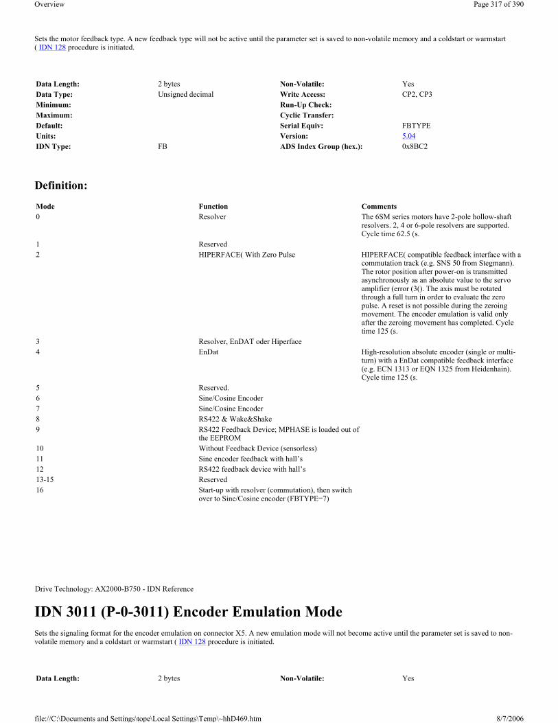
Sets the motor feedback type. A new feedback type will not be active until the parameter set is saved to non-volatile memory and a coldstart or warmstart ( IDN 128 procedure is initiated.
Definition:
IDN 3011 (P-0-3011) Encoder Emulation Mode Sets the signaling format for the encoder emulation on connector X5. A new emulation mode will not become active until the parameter set is saved to non-volatile memory and a coldstart or warmstart ( IDN 128 procedure is initiated.
Data Length: 2 bytes Non-Volatile: YesData Type: Unsigned decimal Write Access: CP2, CP3Minimum: Run-Up Check:Maximum: Cyclic Transfer:Default: Serial Equiv: FBTYPEUnits: Version: 5.04IDN Type: FB ADS Index Group (hex.): 0x8BC2
Mode Function Comments0 Resolver The 6SM series motors have 2-pole hollow-shaft
resolvers. 2, 4 or 6-pole resolvers are supported. Cycle time 62.5 (s.
1 Reserved2 HIPERFACE( With Zero Pulse HIPERFACE( compatible feedback interface with a
commutation track (e.g. SNS 50 from Stegmann). The rotor position after power-on is transmitted asynchronously as an absolute value to the servo amplifier (error (3(). The axis must be rotated through a full turn in order to evaluate the zero pulse. A reset is not possible during the zeroing movement. The encoder emulation is valid only after the zeroing movement has completed. Cycle time 125 (s.
3 Resolver, EnDAT oder Hiperface4 EnDat High-resolution absolute encoder (single or multi-
turn) with a EnDat compatible feedback interface (e.g. ECN 1313 or EQN 1325 from Heidenhain). Cycle time 125 (s.
5 Reserved.6 Sine/Cosine Encoder7 Sine/Cosine Encoder8 RS422 & Wake&Shake9 RS422 Feedback Device; MPHASE is loaded out of
the EEPROM10 Without Feedback Device (sensorless)11 Sine encoder feedback with hall’s12 RS422 feedback device with hall’s13-15 Reserved16 Start-up with resolver (commutation), then switch
over to Sine/Cosine encoder (FBTYPE=7)
Drive Technology: AX2000-B750 - IDN Reference
Data Length: 2 bytes Non-Volatile: Yes
Page 317 of 390Overview
8/7/2006file://C:\Documents and Settings\tope\Local Settings\Temp\~hhD469.htm
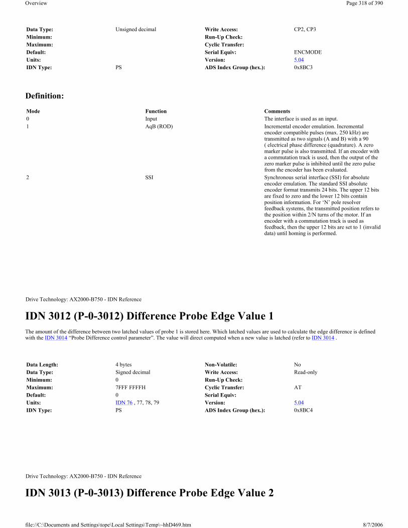
Definition:
IDN 3012 (P-0-3012) Difference Probe Edge Value 1 The amount of the difference between two latched values of probe 1 is stored here. Which latched values are used to calculate the edge difference is defined with the IDN 3014 “Probe Difference control parameter”. The value will direct computed when a new value is latched (refer to IDN 3014 .
IDN 3013 (P-0-3013) Difference Probe Edge Value 2
Data Type: Unsigned decimal Write Access: CP2, CP3Minimum: Run-Up Check:Maximum: Cyclic Transfer:Default: Serial Equiv: ENCMODEUnits: Version: 5.04IDN Type: PS ADS Index Group (hex.): 0x8BC3
Mode Function Comments0 Input The interface is used as an input.1 AqB (ROD) Incremental encoder emulation. Incremental
encoder compatible pulses (max. 250 kHz) are transmitted as two signals (A and B) with a 90( electrical phase difference (quadrature). A zero marker pulse is also transmitted. If an encoder with a commutation track is used, then the output of the zero marker pulse is inhibited until the zero pulse from the encoder has been evaluated.
2 SSI Synchronous serial interface (SSI) for absolute encoder emulation. The standard SSI absolute encoder format transmits 24 bits. The upper 12 bits are fixed to zero and the lower 12 bits contain position information. For ‘N’ pole resolver feedback systems, the transmitted position refers to the position within 2/N turns of the motor. If an encoder with a commutation track is used as feedback, then the upper 12 bits are set to 1 (invalid data) until homing is performed.
Drive Technology: AX2000-B750 - IDN Reference
Data Length: 4 bytes Non-Volatile: NoData Type: Signed decimal Write Access: Read-onlyMinimum: 0 Run-Up Check:Maximum: 7FFF FFFFH Cyclic Transfer: ATDefault: 0 Serial Equiv:Units: IDN 76 , 77, 78, 79 Version: 5.04IDN Type: PS ADS Index Group (hex.): 0x8BC4
Drive Technology: AX2000-B750 - IDN Reference
Page 318 of 390Overview
8/7/2006file://C:\Documents and Settings\tope\Local Settings\Temp\~hhD469.htm

The amount of the difference between two latched values of probe 2 is stored here. Which latched values are used to calculate the edge difference is defined with the IDN 3014 “Probe Difference control parameter”. The value will direct computed when a new value is latched (refer to IDN 3014 .
IDN 3014 (P-0-3014) Probe Difference Control Parameter
Definition:
IDN 3015 (P-0-3015) Hardware Limit Switch Consequence This parameter define the consequence off the Hardware Limit Switch, if the corresponding digital inputs ( IDN 3002 and/or IDN 3003 ) are set to the limit switches. If the hardware limit switch consequence is set to 0, then the Limit switch consequence is a warning. Else if the IDN P3015 is set to 1, then the switch consequence is a fault and the drive ramp down with setting the following fault bits, in IDN 11 bit 15 and in IDN 129 the bit 2. After the reset class 1 diagnostic command ( IDN 99 ) the drive could enable again and move back in the valid range. During the procedure drive controlled homing ( IDN 148 ), the
Data Length: 4 bytes Non-Volatile: NoData Type: Signed decimal Write Access: Read-onlyMinimum: 0 Run-Up Check:Maximum: 7FFF FFFFH Cyclic Transfer: ATDefault: 0 Serial Equiv:Units: IDN 76 , 79 Version: 5.04IDN Type: PS ADS Index Group (hex.): 0x8BC5
Drive Technology: AX2000-B750 - IDN Reference
Data Length: 2 bytes Non-Volatile: NoData Type: Unsigned decimal Write Access: CP2, CP3, CP4Minimum: 0 Run-Up Check:Maximum: 6 Cyclic Transfer:Default: 0 Serial Equiv:Units: Version: 5.04IDN Type: VE ADS Index Group (hex.): 0x8BC6
Value Description0 Difference probe edge function is off1 Compute distance between one positive edge and one negative edge2 Compute distance between one negative edge and one positive edge3 Compute distance between two successive positive edges4 Compute distance between two successive negative edges5 Compute distance between the first positive and negative edge6 Compute distance between the first negative and positive edge
Drive Technology: AX2000-B750 - IDN Reference
Page 319 of 390Overview
8/7/2006file://C:\Documents and Settings\tope\Local Settings\Temp\~hhD469.htm

hardware limit switch could use in the normal way (refer to IDN 3027 .
This parameter define the consequence off the Hardware Limit Switch, if the corresponding digital inputs ( IDN 3002 and/or IDN 3003 ) are set to the limit switches. If the hardware limit switch consequence is set to 0, then the Limit switch consequence is a warning. Else if the IDN IDN 3015 is set to 1, then the switch consequence is a fault and the drive ramp down with setting the following fault bits, in IDN 11 bit 15 and in IDN 129 the bit 2. After the reset class 1 diagnostic command ( IDN 99 ) the drive could enable again and move back in the valid range. During the procedure drive controlled homing ( IDN 148 ), the hardware limit switch could use in the normal way (refer to IDN 3027 .
IDN 3016 (P-0-3016) Reset Command Consequence This parameter define the consequence off the reset class 1 diagnostic command ( IDN 99 ), for faults which require a coldstart. If this IDN is set, faults which require a coldstart will not clear. The reset command will abort with the SC message “Command execution not possible” (refer to IDN 11 , 99 and 129).
IDN 3018 (P-0-3018) Configuration of the Positionlatch This IDN defines, the source of Positioninformation of the latch function, if the digital input 1 and 2 are set for the latch function (IN1MODE = 26 and IN2MODE = 26). If both inputs are select for position latch, with the digital input 2 ( IDN 3031 the Probe 1 function will be support and with the digital input 1 ( IDN 3030 the Probe 1 function will be supported (refer to IDN 169 , 170, 40 and 406). If IN1MODE is different from 26 this IDN IDN 3018(EXTLATCH) has no function , with an edge at the digital input 2 both (Probe 1 and 2) will be latched.
Data Length: 2 bytes Non-Volatile: YesData Type: Unsigned decimal Write Access: CP2, CP3, CP4Minimum: 0 Run-Up Check:Maximum: 1 Cyclic Transfer:Default: 0 Serial Equiv: SERCSET (Bit 0)Units: Version: 5.04IDN Type: VE ADS Index Group (hex.): 0x8BC7
Drive Technology: AX2000-B750 - IDN Reference
Data Length: 2 bytes Non-Volatile: YesData Type: Unsigned decimal Write Access: CP2, CP3, CP4Minimum: 0 Run-Up Check:Maximum: 1 Cyclic Transfer:Default: 0 Serial Equiv: SERCSET (Bit 1)Units: Version: 5.04IDN Type: VE ADS Index Group (hex.): 0x8BC8
Drive Technology: AX2000-B750 - IDN Reference
Data Length: 2 bytes Non-Volatile: YesData Type: Unsigned decimal Write Access: CP2, CP3Minimum: 0 Run-Up Check:Maximum: 2 Cyclic Transfer:Default: 0 Serial Equiv: EXTLATCHUnits: Version: 5.04
Page 320 of 390Overview
8/7/2006file://C:\Documents and Settings\tope\Local Settings\Temp\~hhD469.htm

Definition:
IDN 3019 (P-0-3019) Select of the FPGA Program This IDN select the FPGA program of the drive, which will be download to the FPGA in the initialization.
FPGA = 0: Standard FPGA program
FPGA = 1: Program with Up/Down counter (this allows the usage of a high resolution feedback and Master/ Slave functionality; Program with second counter for latch function on the digital input 1
It exist a third FPGA program, for reading of external SSI encoder as a second encoder. This program is automatically selected if GEARMODE = 7 is selected.
IDN 3020 (P-0-3020) System Rated Current Allows setting the rated output current of the drive/motor system.
IDN Type: FB ADS Index Group (hex.): 0x8BCA
IDN 3000 (IN1MODE) NOT_EQUAL 26
IDN P3001 (IN2MODE) = 26
IDN 3000 (IN1MODE) = 26
IDN 3001 (IN2MODE) = 26
IDN 3031 (IN2) IDN 3030 (IN1) IDN 3031 (IN2) IDN 3030 (IN1) IDN P3018 (EXTLATCH)
Probe1=Motor Fbk.
Probe2=ext. Fbk.
No Latch Function Probe1 = Motor Fbk. Probe2=Motor Fbk. 0Probe1 = Motor Fbk. Probe2=ext. Fbk. (inc.
Encoder)1
Probe1=ext. Fbk. (inc. Encoder)
Probe2=ext. Fbk. (inc. Encoder)
2
Drive Technology: AX2000-B750 - IDN Reference
Data Length: 2 bytes Non-Volatile: YesData Type: Unsigned decimal Write Access: CP2, CP3Minimum: 0 Run-Up Check:Maximum: 1 Cyclic Transfer:Default: 0 Serial Equiv: FPGAUnits: Version: 5.04IDN Type: CT:FS ADS Index Group (hex.): 0x8BCB
Drive Technology: AX2000-B750 - IDN Reference
Data Length: 4 bytes Non-Volatile: yesData Type: Unsigned decimal Write Access: CP2, CP3Minimum: 10% of IDN 112 . Run-Up Check:Maximum: Minimum of IDN 111 and IDN 112 . Cyclic Transfer:
Page 321 of 390Overview
8/7/2006file://C:\Documents and Settings\tope\Local Settings\Temp\~hhD469.htm

IDN 3021 (P-0-3021) Over Speed The maximum motor speed threshold. If the maximum motor speed is exceeded, then an over speed fault ( IDN 129 , bit 9) occurs.
IDN 3022 (P-0-3022) Quick Deceleration Rate The drive uses the quick deceleration rate during an active disable (MDT control bit 15, a fault or a limit switch). The quick deceleration limit is defined as the number of milliseconds required to decelerate from the maximum velocity limit ( IDN 38 , 39, 91) to a standstill.
IDN 3026 (P-0-3026) Non-Volatile Memory Data Checksum A checksum of the data stored within non-volatile memory. The checksum is updated after a “Back-up Working Memory” procedure ( IDN 264 ) has been executed successfully.
Default: 50% of the minimum of IDN 112 . Serial Equiv: ICONTUnits: MA Version: 5.04IDN Type: CT:FS ADS Index Group (hex.): 0x8BCC
Drive Technology: AX2000-B750 - IDN Reference
Data Length: 4 bytes Non-Volatile: YesData Type: Unsigned decimal Write Access: CP2, CP3, CP4Minimum: 0 Run-Up Check:Maximum: 1.2 * IDN 113 Cyclic Transfer:Default: 36 000 000 Serial Equiv: VOSPD * 10 000Units: 0.0 001 RPM Version: 5.04IDN Type: VE:FS ADS Index Group (hex.): 0x8BCD
Drive Technology: AX2000-B750 - IDN Reference
Data Length: 4 bytes Non-Volatile: YesData Type: Signed decimal Write Access: CP2, CP3, CP4Minimum: 1 Run-Up Check:Maximum: 32767 Cyclic Transfer:Default: 10 Serial Equiv: DECSTOPUnits: IDN 160 , 161, 162 Version: 5.04IDN Type: AD ADS Index Group (hex.): 0x8BCE
Drive Technology: AX2000-B750 - IDN Reference
Page 322 of 390Overview
8/7/2006file://C:\Documents and Settings\tope\Local Settings\Temp\~hhD469.htm

IDN 3027 (P-0-3027) Manufacturer Homing Modes Selection of manufacturer defined homing modes. Use IDN 41 , IDN 42 and IDN 147 to set the homing velocity, acceleration and direction. This IDN contains the saved serial command NREF after reset. Write this P IDN or write IDN 147 through the service channel, could change the used homing mode for the drive controlled homing ( IDN 148 ). After or while homing with SERCOS the parameter NREF contains the value of this IDN. A following SAVE command can save this value permanent.
For an explanation of the homing modes 0, 3, 4, 5 and 6 please refer to the Kollmorgen manual “Setup Software SR600.exe for ServoSTAR 600.”
Standard SERCOS homing (mode 1): For an explanation of the standard homing mode, please refer to the IEC 61491 Standard or to the Kollmorgen manual “Setup Software SR600.exe for ServoSTAR 600.” This is the default value also for IDN 147 (refer to IDN 147 ).
Hardware Limit Switch Homing (mode 2): This homing mode uses a hardware limit switch as the home switch. The following diagrams show this homing option, without reference switch, in both the positive and the negative directions of motion with zero mark of the feedback.
Warning: Hardware limit switches must be present and connected. The appropriate limit switch functions must be switched on, i.e. digital input 3 must be PSTOP ( IDN 3002 mode 2) and/or digital input 4 must be NSTOP ( IDN 3003 mode 3).
Mechanical Stop Homing (mode 7): This homing mode uses the mechanical stop instead of a separate homing switch or a hardware limit switch. Set the maximum current (torque) limit through IDN 92 , to limit the torque applied against the mechanical stop. The mechanical stop must be fixed in place and hardware limit switches must be disabled in the direction of the mechanical stop. It is not possible to re-enable or disable hardware limit switches in CP4. When motion toward the stop is no longer possible, the following error increases and triggers a movement back to the first zero mark. The following diagrams show this homing option, in both the positive and the negative directions of motion.
Definition:
Data Length: 2 bytes Non-Volatile: YesData Type: Unsigned decimal Write Access: Read-onlyMinimum: Run-Up Check:Maximum: Cyclic Transfer:Default: Serial Equiv:Units: Version: 5.04IDN Type: SC ADS Index Group (hex.): 0x8BD2
Drive Technology: AX2000-B750 - IDN Reference
Data Length: 2 bytes Non-Volatile: NoData Type: Unsigned decimal Write Access: CP2, CP3, CP4Minimum: 0 Run-Up Check:Maximum: 7 Cyclic Transfer:Default: 1 Serial Equiv: NREFUnits: Version: 5.04IDN Type: PS:VE ADS Index Group (hex.): 0x8BD3
Mode Function IDN 147 (bits 7-0)0 Set reference point to the actual position 1110 0xxx1 Traverse to the reference switch with zero-mark
recognition1000 010x
2 Move to hardware limit-switch, with zero-mark recognition
1000 010x
3 Move to reference switch, without zero-mark recognition
1100 010x
Page 323 of 390Overview
8/7/2006file://C:\Documents and Settings\tope\Local Settings\Temp\~hhD469.htm

IDN 3030 (P-0-3030) Configurable I/O: Digital Input 1 Status Reflects the state of a digital input (connector X3 pins 11 - 14) in the least significant bit of the IDN.
IDN 3031 (P-0-3031) Configurable I/O: Digital Input 2 Status Reflects the state of a digital input (connector X3 pins 11 - 14) in the least significant bit of the IDN.
4 Move to hardware limit-switch, without zero-mark recognition
1100 010x
5 Move to the next zero-mark of the feedback unit 1010 0xxx6 Set reference at actual position, without loosing
target position1110 0xxx
7 Move to mechanical stop with zero-mark recognition
1000 010x
8 Move to absolute SSI-position9 Move to mechanical stop without zero-mark
recognition
Drive Technology: AX2000-B750 - IDN Reference
Data Length: 2 bytes Non-Volatile: NoData Type: Binary Write Access: Read-onlyMinimum: Run-Up Check:Maximum: Cyclic Transfer: ATDefault: Serial Equiv: IN1, IN2, IN3, IN4Units: Version: 5.04IDN Type: IO ADS Index Group (hex.): 0x8BD6
Drive Technology: AX2000-B750 - IDN Reference
Data Length: 2 bytes Non-Volatile: NoData Type: Binary Write Access: Read-onlyMinimum: Run-Up Check:Maximum: Cyclic Transfer: ATDefault: Serial Equiv: IN1, IN2, IN3, IN4Units: Version: 5.04IDN Type: IO ADS Index Group (hex.): 0x8BD7
Page 324 of 390Overview
8/7/2006file://C:\Documents and Settings\tope\Local Settings\Temp\~hhD469.htm
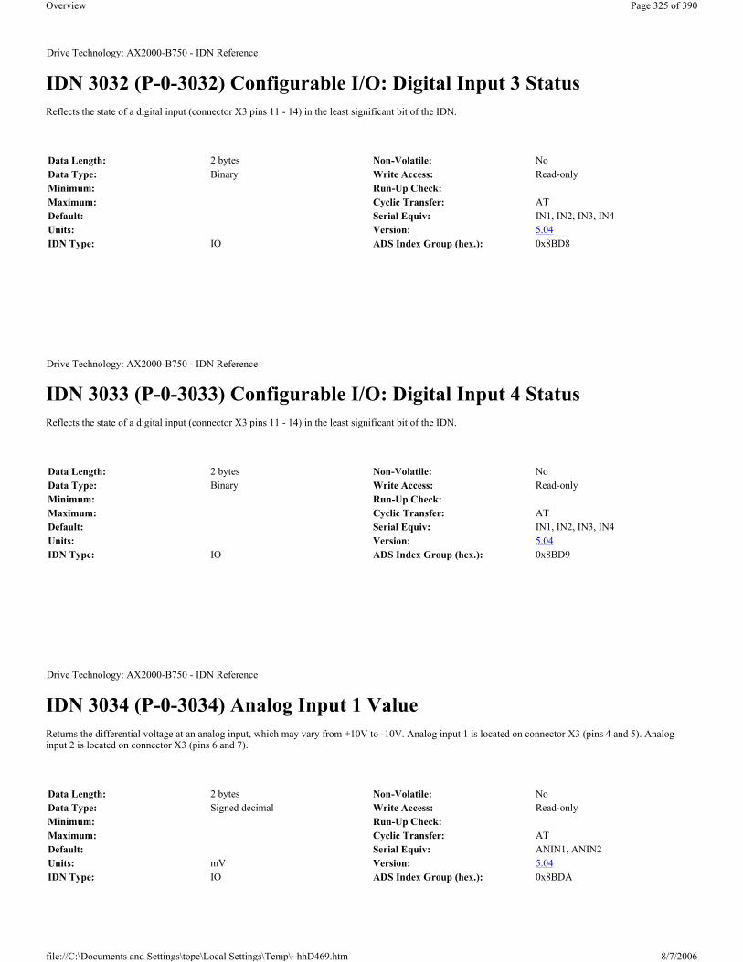
IDN 3032 (P-0-3032) Configurable I/O: Digital Input 3 Status Reflects the state of a digital input (connector X3 pins 11 - 14) in the least significant bit of the IDN.
IDN 3033 (P-0-3033) Configurable I/O: Digital Input 4 Status Reflects the state of a digital input (connector X3 pins 11 - 14) in the least significant bit of the IDN.
IDN 3034 (P-0-3034) Analog Input 1 Value Returns the differential voltage at an analog input, which may vary from +10V to -10V. Analog input 1 is located on connector X3 (pins 4 and 5). Analog input 2 is located on connector X3 (pins 6 and 7).
Drive Technology: AX2000-B750 - IDN Reference
Data Length: 2 bytes Non-Volatile: NoData Type: Binary Write Access: Read-onlyMinimum: Run-Up Check:Maximum: Cyclic Transfer: ATDefault: Serial Equiv: IN1, IN2, IN3, IN4Units: Version: 5.04IDN Type: IO ADS Index Group (hex.): 0x8BD8
Drive Technology: AX2000-B750 - IDN Reference
Data Length: 2 bytes Non-Volatile: NoData Type: Binary Write Access: Read-onlyMinimum: Run-Up Check:Maximum: Cyclic Transfer: ATDefault: Serial Equiv: IN1, IN2, IN3, IN4Units: Version: 5.04IDN Type: IO ADS Index Group (hex.): 0x8BD9
Drive Technology: AX2000-B750 - IDN Reference
Data Length: 2 bytes Non-Volatile: NoData Type: Signed decimal Write Access: Read-onlyMinimum: Run-Up Check:Maximum: Cyclic Transfer: ATDefault: Serial Equiv: ANIN1, ANIN2Units: mV Version: 5.04IDN Type: IO ADS Index Group (hex.): 0x8BDA
Page 325 of 390Overview
8/7/2006file://C:\Documents and Settings\tope\Local Settings\Temp\~hhD469.htm

IDN 3035 (P-0-3035) Analog Input 2 Value Returns the differential voltage at an analog input, which may vary from +10V to -10V. Analog input 1 is located on connector X3 (pins 4 and 5). Analog input 2 is located on connector X3 (pins 6 and 7).
IDN 3036 (P-0-3036) Configurable I/O: Digital Output 1 Control/Status The master may set and read the state of a digital output in the least significant bit of the corresponding digital output control/status IDN.
IDN 3037 (P-0-3037) Configurable I/O: Digital Output 2 Control/Status The master may set and read the state of a digital output in the least significant bit of the corresponding digital output control/status IDN.
Drive Technology: AX2000-B750 - IDN Reference
Data Length: 2 bytes Non-Volatile: NoData Type: Signed decimal Write Access: Read-onlyMinimum: Run-Up Check:Maximum: Cyclic Transfer: ATDefault: Serial Equiv: ANIN1, ANIN2Units: mV Version: 5.04IDN Type: IO ADS Index Group (hex.): 0x8BDB
Drive Technology: AX2000-B750 - IDN Reference
Data Length: 2 bytes Non-Volatile: NoData Type: Binary Write Access: CP2, CP3, CP4Minimum: Run-Up Check:Maximum: Cyclic Transfer: MDTDefault: 0 Serial Equiv: O1, O2Units: Version: 5.04IDN Type: IO ADS Index Group (hex.): 0x8BDC
Drive Technology: AX2000-B750 - IDN Reference
Data Length: 2 bytes Non-Volatile: NoData Type: Binary Write Access: CP2, CP3, CP4Minimum: Run-Up Check:Maximum: Cyclic Transfer: MDT
Page 326 of 390Overview
8/7/2006file://C:\Documents and Settings\tope\Local Settings\Temp\~hhD469.htm
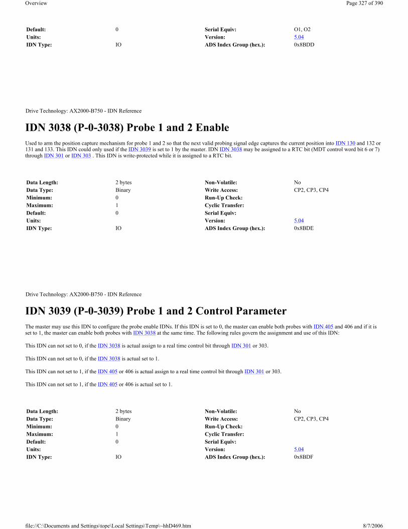
IDN 3038 (P-0-3038) Probe 1 and 2 Enable Used to arm the position capture mechanism for probe 1 and 2 so that the next valid probing signal edge captures the current position into IDN 130 and 132 or 131 and 133. This IDN could only used if the IDN 3039 is set to 1 by the master. IDN IDN 3038 may be assigned to a RTC bit (MDT control word bit 6 or 7) through IDN 301 or IDN 303 . This IDN is write-protected while it is assigned to a RTC bit.
IDN 3039 (P-0-3039) Probe 1 and 2 Control Parameter The master may use this IDN to configure the probe enable IDNs. If this IDN is set to 0, the master can enable both probes with IDN 405 and 406 and if it is set to 1, the master can enable both probes with IDN 3038 at the same time. The following rules govern the assignment and use of this IDN:
This IDN can not set to 0, if the IDN 3038 is actual assign to a real time control bit through IDN 301 or 303.
This IDN can not set to 0, if the IDN 3038 is actual set to 1.
This IDN can not set to 1, if the IDN 405 or 406 is actual assign to a real time control bit through IDN 301 or 303.
This IDN can not set to 1, if the IDN 405 or 406 is actual set to 1.
Default: 0 Serial Equiv: O1, O2Units: Version: 5.04IDN Type: IO ADS Index Group (hex.): 0x8BDD
Drive Technology: AX2000-B750 - IDN Reference
Data Length: 2 bytes Non-Volatile: NoData Type: Binary Write Access: CP2, CP3, CP4Minimum: 0 Run-Up Check:Maximum: 1 Cyclic Transfer:Default: 0 Serial Equiv:Units: Version: 5.04IDN Type: IO ADS Index Group (hex.): 0x8BDE
Drive Technology: AX2000-B750 - IDN Reference
Data Length: 2 bytes Non-Volatile: NoData Type: Binary Write Access: CP2, CP3, CP4Minimum: 0 Run-Up Check:Maximum: 1 Cyclic Transfer:Default: 0 Serial Equiv:Units: Version: 5.04IDN Type: IO ADS Index Group (hex.): 0x8BDF
Page 327 of 390Overview
8/7/2006file://C:\Documents and Settings\tope\Local Settings\Temp\~hhD469.htm

IDN 3040 (P-0-3040) Interpolation Method The master may determine the fine interpolation method within the drive with this IDN. If this IDN is set to 1 the drive work, by a 3 ms and 4 ms cycle time, with a spline interpolation for the command values instead of a liner interpolation.
IDN 3041 (P-0-3041) Position Switch On/Off Parameter
IDN 3042 (P-0-3042) Position Switch Enable/Disable Parameter This IDN could use to enable or disable the check of each position switch point for the position switch flag parameter ( IDN 59 ) (refer to IDN 59 , IDN 3041 ,3043 and P3044).
This IDN could use to enable or disable the check of each position switch point for the position switch flag parameter ( IDN 59 ) (refer to IDN 59 , IDN 3041 ,3043 and IDN 3044 ).
Drive Technology: AX2000-B750 - IDN Reference
Data Length: 2 bytes Non-Volatile: NoData Type: Binary Write Access: CP2, CP3, CP4Minimum: 0 Run-Up Check:Maximum: 1 Cyclic Transfer:Default: 0 Serial Equiv:Units: Version: 5.04IDN Type: IO ADS Index Group (hex.): 0x8BE0
Drive Technology: AX2000-B750 - IDN Reference
Data Length: 2 bytes Non-Volatile: YesData Type: Binary Write Access: CP2, CP3Minimum: 0 Run-Up Check:Maximum: 1 Cyclic Transfer:Default: 0 Serial Equiv: WPOSUnits: Version: 5.04IDN Type: PS ADS Index Group (hex.): 0x8BE1
Drive Technology: AX2000-B750 - IDN Reference
Data Length: 2 bytes Non-Volatile: YesData Type: Binary Write Access: CP2, CP3, CP4Minimum: 0000H Run-Up Check:Maximum: 00FFH Cyclic Transfer:Default: 0 Serial Equiv: WPOSE
Page 328 of 390Overview
8/7/2006file://C:\Documents and Settings\tope\Local Settings\Temp\~hhD469.htm

Definition:
IDN 3043 (P-0-3043) Position Switch Polarity Parameter With this IDN it is possible to select the polarity for each position switch flag to the corresponding flag bit ( IDN 59 ) or the digital output (refer to IDN 59 ,IDN 3041 , 3042 and IDN 3044 ).
With this functionality it is possible to implement a cam function with a positive or negative polarity.
Application Example : Positive Cam Function
IDN 60 = 2/8 Revolution IDN 3041 0001Hex IDN 3042 = 0003Hex
IDN 61 = 3/8 Revolution IDN IDN 3043 = 0002Hex IDN 3044 = 0
IDN 3005 = 41 IDN 3007 = 0003Hex
Application Example : Negative Cam Function
IDN 60 = 2/8 Revolution IDN 3041 0001Hex IDN 3042 = 0003Hex
IDN 61 = 3/8 Revolution IDN IDN 3043 = 0001Hex IDN 3044 = 0
IDN 3005 = 40 IDN 3007 = 0003Hex
Definition:
Units: Version: 5.04IDN Type: PS ADS Index Group (hex.): 0x8BE2
Bit Description SettingLSB 0 Position switch point 1 ( IDN 60 ) 0 = Disable
1 = Enable
Position Switch Flag
1 Position switch point 2 ( IDN 61 )2 Position switch point 3 ( IDN 62 )3 Position switch point 4 ( IDN 63 )4 Position switch point 5 ( IDN 64 )5 Position switch point 6 ( IDN 65 )6 Position switch point 7 ( IDN 66 )7 Position switch point 8 ( IDN 67 )8-15 Reserved
Drive Technology: AX2000-B750 - IDN Reference
Data Length: 2 bytes Non-Volatile: YesData Type: Binary Write Access: CP2, CP3, CP4Minimum: 0000H Run-Up Check:Maximum: 00FFH Cyclic Transfer:Default: 0 Serial Equiv: WPOSPUnits: Version: 5.04IDN Type: PS ADS Index Group (hex.): 0x8BE3
Page 329 of 390Overview
8/7/2006file://C:\Documents and Settings\tope\Local Settings\Temp\~hhD469.htm

IDN 3044 (P-0-3044) Kind Of Position Switch Parameter With this IDN it is possible to select the kind of the position check for each position switch flag to the corresponding flag bit ( IDN 59 ) or the digital output (refer to IDN 59 , IDN 3041 , 3042 and P3043).
With this IDN it is possible to select the kind of the position check for each position switch flag to the corresponding flag bit ( IDN 59 ) or the digital output (refer to IDN 59 , IDN 3041 , 3042 and IDN 3043 ).
Definition:
Bit Description SettingLSB 0
Position switch point 1 ( IDN 60 ) 0= The flag will set to “1” if the position feedback is greatern than or equal to the position switch point.
1 = The flag will set to “0” if the position feedback value is smaller than the position switching point.
1 Position switch point 2 ( IDN 61 )2 Position switch point 3 ( IDN 62 )3 Position switch point 4 ( IDN 63 )4 Position switch point 5 ( IDN 64 )5 Position switch point 6 ( IDN 65 )6 Position switch point 7 ( IDN 66 )7 Position switch point 8 ( IDN 67 )8-15 Reserved
Drive Technology: AX2000-B750 - IDN Reference
Data Length: 2 bytes Non-Volatile: YesData Type: Binary Write Access: CP2, CP3, CP4Minimum: 0000H Run-Up Check:Maximum: 00FFH Cyclic Transfer:Default: 0 Serial Equiv: WPOSXUnits: Version: 5.04IDN Type: PS ADS Index Group (hex.): 0x8BE4
Bit Description SettingLSB 0 Position switch point 1 ( IDN 60 ) 0 = The position check is operating the hole time.
1 = The position flag is check once. The corresponding bit in IDN 59 will set and latched and the corresponding enable bit in IDN 3042 will reset.
1 Position switch point 2 ( IDN 61 )2 Position switch point 3 ( IDN 62 )3 Position switch point 4 ( IDN 63 )4 Position switch point 5 ( IDN 64 )5 Position switch point 6 ( IDN 65 )6 Position switch point 7 ( IDN 66 )7 Position switch point 8 ( IDN 67 )8-15 Reserved
Page 330 of 390Overview
8/7/2006file://C:\Documents and Settings\tope\Local Settings\Temp\~hhD469.htm
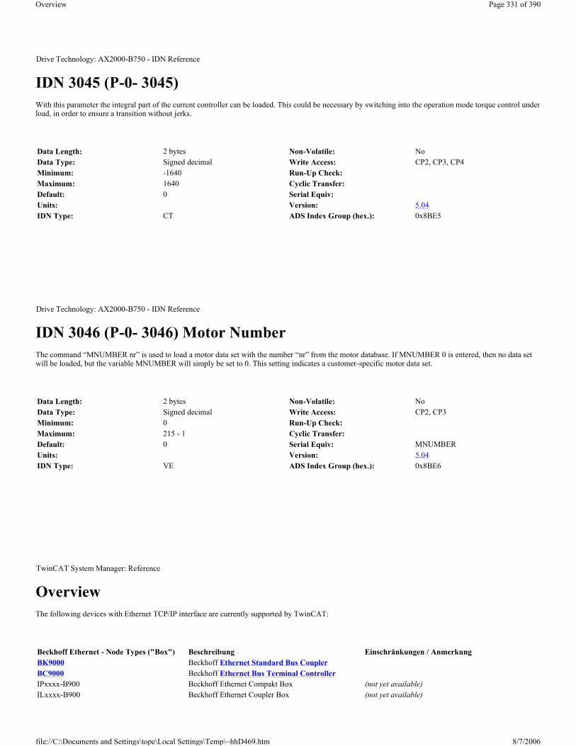
IDN 3045 (P-0- 3045) With this parameter the integral part of the current controller can be loaded. This could be necessary by switching into the operation mode torque control under load, in order to ensure a transition without jerks.
IDN 3046 (P-0- 3046) Motor Number The command “MNUMBER nr” is used to load a motor data set with the number “nr” from the motor database. If MNUMBER 0 is entered, then no data set will be loaded, but the variable MNUMBER will simply be set to 0. This setting indicates a customer-specific motor data set.
Overview The following devices with Ethernet TCP/IP interface are currently supported by TwinCAT:
Drive Technology: AX2000-B750 - IDN Reference
Data Length: 2 bytes Non-Volatile: NoData Type: Signed decimal Write Access: CP2, CP3, CP4Minimum: -1640 Run-Up Check:Maximum: 1640 Cyclic Transfer:Default: 0 Serial Equiv:Units: Version: 5.04IDN Type: CT ADS Index Group (hex.): 0x8BE5
Drive Technology: AX2000-B750 - IDN Reference
Data Length: 2 bytes Non-Volatile: NoData Type: Signed decimal Write Access: CP2, CP3Minimum: 0 Run-Up Check:Maximum: 215 - 1 Cyclic Transfer:Default: 0 Serial Equiv: MNUMBERUnits: Version: 5.04IDN Type: VE ADS Index Group (hex.): 0x8BE6
TwinCAT System Manager: Reference
Beckhoff Ethernet - Node Types ("Box") Beschreibung Einschränkungen / Anmerkung BK9000 Beckhoff Ethernet Standard Bus CouplerBC9000 Beckhoff Ethernet Bus Terminal ControllerIPxxxx-B900 Beckhoff Ethernet Compakt Box (not yet available)ILxxxx-B900 Beckhoff Ethernet Coupler Box (not yet available)
Page 331 of 390Overview
8/7/2006file://C:\Documents and Settings\tope\Local Settings\Temp\~hhD469.htm

Overview The following devices for Beckhoff TwinCAT Real-Time Ethernet are currently supported by TwinCAT:
Hint:
For a description how to install the Beckhoff Real-Time Ethernet driver, see ...
Network Variable Publisher The Beckhoff TwinCAT Real-Time Ethernet solution contains from TwinCAT v2.9 on the ability to configure variables for deterministic data exchange between several TwinCAT-based controllers. The last could be other TwinCAT PCs or CX controllers. These variables are the so-called Network Variables.For this solution it is required to configure the Ethernet Miniport (Real-Time) I/O device type at first. For an Overview of TwinCAT Real-Time Ethernet devices, see..
The Publisher is the send-type network variable. It sends its informations out without waiting for acknowledgement. The communication is only monitored by the Subscriber.
"General" dialog
Standard dialog as for all TwinCAT I/O devices. Nevertheless, a descriptive name for this Publisher (sender) should be edited here. Additionally, a useful comment (i.e. about the target/subscriber this publisher sends its data to) could be very helpful.
Id: A Real-Time Ethernet Publisher ident. number.
Hint:
ILxxxx-C900 Beckhoff Ethernet PLC Box (not yet available)
TwinCAT System Manager: Reference
Real-Time Ethernet - Node Types ("Box") Description Restrictions / Comment
AX2000-B900 AX20xx drive with optional Real-Time Ethernet interface card
AX2000-B900 Ethernet interface firmware >= 'B8' required
BK9000 BK9000 for Beckhoff TwinCAT Real-Time Ethernet BK9000 firmware >= 'B8' required
Network Variable "Publisher" Beckhoff TwinCAT target system variable as "Publisher"
Network Variable "Subscriber" Beckhoff TwinCAT target system variable as "Subscriber"
TwinCAT System Manager: Reference
Page 332 of 390Overview
8/7/2006file://C:\Documents and Settings\tope\Local Settings\Temp\~hhD469.htm

If several Publisher variables have to be set up in same network at other TwinCAT controllers, make sure that they all have network-unique Id's (means in above case for instance, that '1' is already in use and can't be assigned to a second Publisher network variable).
"Publish" dialog
Sending Options
Broadcast: If this option is selected and the node receives the Ethernet frame in its receiving queue, it evaluates whether the data is addressed to him or not. This is not a very "economical" way of communication.
Multicast: If this option is selected, the Ethernet frame is getting evaluated by all attached nodes of the subnet. But instead of processing it with the receive queue, the Ethernet controller detects whether the data is for "him" or not.
Unicast: If selected, the switch opens parallel communication paths and forwards the Ethernet frame directly to the appropriate Subscriber (receiver).
MAC Address: Subscriber MAC Address. For further informations, see: Ethernet Miniport (Real-Time)
AMS Netid: ...
Data Exchange: see: BK9000
VLAN Support: see: BK9000
Diagnosis
Inputs
Outputs
Variable DescriptionFrameState Real-Time Ethernet frame status information as WORD (or UINT) variable, assumes the following values:
0x0001 = Not sent (frame skipped), means FrameCtrl is currently = '1' 0x0002 = Error (frame oversized)
Variable DescriptionFrameCtrl Real-Time Ethernet frame control as WORD (or UINT) variable, accepts the following values:
0x0001 = Disable sending
Page 333 of 390Overview
8/7/2006file://C:\Documents and Settings\tope\Local Settings\Temp\~hhD469.htm

Context menu
Insert Network Variable: Please see description under Subscriber
Other items: Please see Adding Input/Output Modules
Publisher variable - Outputs
Network Variable Subscriber The Beckhoff TwinCAT Real-Time Ethernet solution contains from TwinCAT v2.9 on the ability to configure variables for deterministic data exchange between several TwinCAT-based controllers. The last could be other TwinCAT PCs or CX100x controllers. For this solution it is required to configure the Ethernet Miniport (Real-Time) I/O device type first. For an Overview of TwinCAT Real-Time Ethernet devices, see..
The Subscriber is the receive-type variable of the TwinCAT target system. It receives values from the Publisher variable of the networked TwinCAT controller.
"General" dialog
Standard dialog as for all TwinCAT I/O devices. Nevertheless, a descriptive name for this Subscriber should be edited here. Additionally, a useful comment (i.e. about the Publisher the data is coming from) could be very helpful.
Diagnosis
Inputs
Outputs
If FrameCtrl receives above value (e.g. from mapped PLC variable), this frame doesn't get sent. The sending will be continued if FrameCtrl has been released again (= '0'). The FrameState variable assumes the value '1' in the meantime. The related subscriber variables CycleIndex and Quality will notice on the other side that the frame transmission has been suppressed.
Variable Data type DescriptionVarCtrl UINT Can be set to 0x0001 = Disable publishing
The transmission of this publisher variable is suppressed in above case (until VarCtrl becomes '0' again). The subscriber CycleIndex variable stays static and the Quality counts up (to a maximum of 65535).
VarData as specified To be linked to the output variable (e.g. PLC output) to be transmitted via TwinCAT Real-Time Ethernet.TwinCAT System Manager: Reference
Variable DescriptionFrameState This variable is currently not in use at subscribers
Page 334 of 390Overview
8/7/2006file://C:\Documents and Settings\tope\Local Settings\Temp\~hhD469.htm

Context menu
Insert Network Variable: Calls the following dialog:
Browse for Computer: Calls the Choose Target System dialog.
Browse for File: Calls the file selection dialog for existing TwinCAT System Manager project files (*.tsm). If Publisher variables have been found in the selected file, these variables get listed in the Name, Id, Size, Type section of above dialog.
Create new Variable: Calls the Insert Network Variable dialog described below.
"Insert Network Variable" Dialog
Variable DescriptionFrameCtrl This variable is currently not in use at subscribers
Page 335 of 390Overview
8/7/2006file://C:\Documents and Settings\tope\Local Settings\Temp\~hhD469.htm

Name: A descriptive name for the subscriber variable should be edited here.
Id: ...
Comment: Space for a helpful comment about this subscriber variable.
Type: Lists available data types for this variable. The appropriate type has to be selected here. This could be standard data type, an array or a complex structure. If e.g. the process image of the configured PLC project contains a user-defined data type (i.e. a structure) with the name 'MyType', it would show up on the list like shown above.
Subscriber variable - Inputs
AX2xxx-B900 Axis (Real-Time Ethernet Interface) The Beckhoff AX2000 resp. AX2500 drive is available with different (optional) Fieldbus interfaces. One variant is the AX2000 with TwinCAT Real-Time Ethernet interface (part no.: AX20xx-B900). The AX2xxx-B900 is implemented in TwinCAT as a real-time capable device if used in an Ethernet Miniportsubnet. For an Overview of all currently supported devices for Ethernet Miniport, please see...
Hint: If Real-Time Ethernet and "normal" Ethernet are both used on the same system with two different network adapters, the subnet addresses of these adpaters (NICs) must differ! The AX2xxx-B900 has to be configured with the same subnet address (first two quadruples) as the Ethernet Miniport adapter in this case, of course.
"AX2000-B900" tab
Variable Data type DescriptionVarState UINT This variable is currently not in use Quality UINT This variable shows how "old" the value of this subscriber variable is. Means, every 100µs the data variable is
not updated this value gets increased by 1. This could happen e.g. when the link of the network connection is lost. After re-establishing it, the value is set back to 0 again. Max. value of Quality is 65535.
CycleIndex UINT This variable value increments with every I/O cycle the publisher does. The subscriber extracts this value out of the Ethernet frame.
VarData as specified To be linked to input variable (e.g. to PLC input).
Variable Data type DescriptionVarCtrl UINT This variable is currently not in use TwinCAT System Manager: Reference
Page 336 of 390Overview
8/7/2006file://C:\Documents and Settings\tope\Local Settings\Temp\~hhD469.htm

Diagnosis: This checkbox is deactivated for the AX2000-B900.
2 Byte PLC Interface: This checkbox is deactivated for the AX2000-B900.
No Real Time Flag: If the AX2000-B900 belongs to an Ethernet Miniport subnet, but is not intended to be used for real-time data exchange, this box has to be checked.
K-Bus Update: Estimated internal update time for the -B900 interface.
Firmware Update: The firmware update dialog is called by pushing this button. With this function, the most recent firmware version for the -B900 slot interface can be loaded (via LAN or COM port).
Data Exchange:
- Divider: see: BK9000
- Modulo: see: BK9000
VLAN Support:
- Enable: Activates the VLAN support (see: IEEE 802.1Q, RFC3518) for the communication with this device. If enabled, the Ethernet frame is getting extended by 4 byte. These extension is called VLAN tag and contains for instance informations about ID and priority .
- Priority: A 3 bit VLAN priority value as defined by IEEE 802.1D. Most switches contain two queues, a high and a low priority one. Therefore priorities between 0..3 are assigned to the high priority queue and 4..7 are assigned to the low priority queue at those switch types.
- Id: 12 bit VLAN identifier number as defined by IEEE 802.1Q.
"IP Address" Tab
For further informations about this tab, see -> "IP Address" Tab.
"ADS Commands" Tab
For further informations about this tab, see -> "ADS Command Window".
"Online" Tab
For further informations about this tab, see: "AX2xxx Drive Tab - Online".
"Inputs" Tab
For further informations about this tab, see: "AX2xxx Drive Tab - Inputs"
"Outputs" Tab
For further informations about this tab, see: "AX2xxx Drive Tab - Outputs"
Page 337 of 390Overview
8/7/2006file://C:\Documents and Settings\tope\Local Settings\Temp\~hhD469.htm

Diagnosis Inputs
The below shown variable DriveError has been added manually!
If the variables DriveError, DriveState2 (default) and DriveState3 (default) are added as described under AX2xxx Drive Tab - Inputs, they can be used for diagnosis purposes. If they are linked to a TwinCAT PLC process image for instance, they can be evaluated inside the PLC run-time system.
For further informations about the error and warning codes of the AX2xxx drive, see: "AX2xxxx Drive - Status and Error Codes".
Overview With EtherCAT the division into boxes and bus terminals does not exist any more. Every terminal has an EtherCAT Slave controller(ESC) integrated and therefore is a full EtherCAT slave device. An EtherCAT slave device can either be added to the EtherCAT(Direct Mode) Device or to the Real-Time Ethernet device. The basic property pages for the EtherCAT slaves devices are the same for every connected device, be it a terminal, a drive or a bus coupler.
Intelligent devices( for instance drives) that support a mailbox protocol for asynchronous communication have one or more of the following additional tabs:
EtherCAT Slave Device EtherCAT Slave Device "EtherCAT" tab:
TwinCAT System Manager: EtherCAT
Tab DescriptionGeneral General information.EtherCAT EtherCAT specific configuration.Process Data Configuration of the process data.Online Displays online information about the EtherCAT slave device.
Tab DescriptionMailbox Mailbox configuration
StartupThe "Startup" tab is displayed, if the slave device has a mailbox and supports either the CANopen over EtherCAT(Coe) protocol or the Servo Drive over EtherCAT(SoE) protocol. With the help of the "Startup" tab the user can configure which download requests are sent to the mailbox during startup.
Coe-OnlineIf the EtherCAT slave device supports the CANopen over EtherCAT(CoE) protocol the additional tab "CoE-Online" appears. This tab enables the user to view the contents of the object dictionary of the slave(SDO-Upload) and to change the contents of an object in the dictionary(SDO-Upload).
SoE-Online If the EtherCAT slave device supports the CANopen over EtherCAT(SoE) protocol the additional tab "SoE-Online" appears. TwinCAT System Manager: EtherCAT
Page 338 of 390Overview
8/7/2006file://C:\Documents and Settings\tope\Local Settings\Temp\~hhD469.htm

Type: Name of the EtherCAT Slave device.
Product/Revision: Product and Revision number of the EtherCAT slave device.
Auto Inc Addr: The Auto Increment Address of the EtherCAT slave device. Auto-increment addressing can be used to address each slave device via its physical position in the communication ring. Auto-increment addressing is used during the start-up phase, during which the master assigns the EtherCAT Address to the slaves. The first slave in the ring has an address of 0 and for each following the addresses is decremented (0xFFFF(-1),0xFFFE(-2) etc.).
EtherCAT Addr: The fixed Address of the EtherCAT slave device. This address is set by the master during the start-up phase. To change the default value you have to check the box left to the address.
Advanced Settings: Opens the Advanced Settings dialog.
Previous Port: The port and name of the EtherCAT slave device this device is connected to. If it is possible to connect this device to a different without changing the order of the EtherCAT slave devices in the communication ring, the combo box is enabled and one can select the EtherCAT device this device should be connected to.
EtherCAT Slave Device "Process Data" tab: Displays the configuration of the process data. The input and output variables of the slave device are displayed as CANopen Process Data Objects(PDO). If supported by the slave device this dialog enables the user to select a different PDO via PDO Assignment and to alter to contents of an individual PDO.
Sync Manager: Lists the configuration of the sync managers. If the device has a mailbox the sync manager 0 is used for the mailbox output and the sync manager 1 is used for the mailbox input. The next Sync Manager is used for the process data outputs and the last sync manager for the process data inputs. If an item is selected the corresponding PDO Assignment is displayed in the list view "PDO Assignment(0x1C1Sm)" (where Sm is the number of the sync
Page 339 of 390Overview
8/7/2006file://C:\Documents and Settings\tope\Local Settings\Temp\~hhD469.htm

manager).
PDO Assignment(0x1C1Sm) (where Sm is the number of the sync manager): PDO Assignment for the selected Sync Manager. Here all PDOs defined for this Sync Manager type are listed with their index. If the Outputs Sync Manager is selected in the "Sync Manager" list view, all TxPDOs are displayed. If the Inputs Sync Manager is selected, all RxPDOs are selected. The checked items are the PDOs, that take part in the process data communication. These PDOs are displayed in the tree view of the System Manager as variables of this EtherCAT slave device. The name of the variable is identical to the Parameter "Name" of the PDO, as displayed in the list view "PDO List". If an item in the "PDO Assignment" list is disabled(unchecked and gray), it indicates that this item is excluded for the current PDO assignment. To be able to select this PDO, one has to uncheck the currently checked PDOs.
PDO List: Lists all PDOs supported by this EtherCAT slave device. The content of the selected PDO is displayed in the "PDO Content(index of PDO):" list view. By double clicking on an entry one can change the configuration of the PDO.
PDO Content(Index of PDO ):
Displays the contents of a PDO. If the Fixed Content Flag(Flag = F) of the PDO is not set, the content can be changed by the user.
Download:
If the device is an intelligent device and has a mailbox, the configuration of the PDOs and the PDO assignments can be downloaded to the device. This is an optional feature and is not supported by all slave devices.
PDO Assignment: If this box is checked, the PDO Assignment configured in the "PDO Assignment" list view is downloaded to the slave device during startup. The necessary commands sent to the device can be viewed in the "Startup" tab.
PDO Configuration: If this box is checked, the configuration of the individual PDOs as displayed in the "PDO List" and PDO Content" view are downloaded to the EtherCAT slave device.
EtherCAT Slave Device "Online" tab: Displays online information about the EtherCAT slave device.
State Machine:
Init: Tries to set the EtherCAT slave device to the Init State.
Pre-Op: Tries to set the EtherCAT slave device to the Pre-Operational State.
Column Description:Index Index of the PDO.Size Size of the PDO in bytes.Name Name of the PDO. If this PDO is assigned to a sync manager, it appears as variable of the slave device with this Parameter as name.
FlagsF Fixed Content. The content of the PDO is fixed and cannot be changed by the System Manager.
M Mandatory PDO. This PDO is mandatory and therefore must be assigned to a Sync Manager. As a consequence one cannot uncheck this item in the "PDO Assignment" list.
SM The Sync Manager this PDO is assigned to. If this entry is empty the PDO does not take part in the process data communication.SU Sync Unit this PDO is assigned to.
Page 340 of 390Overview
8/7/2006file://C:\Documents and Settings\tope\Local Settings\Temp\~hhD469.htm

Safe-Op: Tries to set the EtherCAT slave device to the Safe-Operational State.
Op: Tries to set the EtherCAT slave device to the Operational State.
Bootstrap: Tries to set the EtherCAT slave device to the Bootstrap State.
Clear Error: Tries to clear the error flag. If a slave device fails to change to another state, it sets the error flag. For instance a slave device is currently in the Pre-Operational state. Then the master requests the Safe-Operational state. If the slave device fails to change to Safe-Operational, it sets the error flag. The current state would be displayed as "ERR PREOP". After pressing the Clear Error the error flag is cleared and the current state would be displayed as "PREOP" again.
Current State: Current EtherCAT State of the slave device.
Requested State: EtherCAT State the master tried to set the slave to.
Dll Status:
The Data Link Layer (DLL) Status contains status information concerning the individual ports(A, B and C) of a slave device. Four different values for the DLL status are possible:
EtherCAT Slave Device "Mailbox" tab: If the EtherCAT slave devices supports one or more mailbox protocols the additional tab "mailbox" appears. In this dialog the supported mailbox protocols are listed and the configuration of the mailbox can be changed.
Mailbox Polling:
Cyclic: If this box is checked, the master cyclically tries to read out the mailbox .
Cycle Time(ms): If the "Cyclic" box is checked, this value determines how often the master reads out the mailbox of the slave.
State Change: If this box is checked, the master checks a status bit of the slave, to determine if unread data is available in the mailbox. Only then does the master read out the total mailbox. This mode is more efficient than the "Cyclic" mode, because the master can read out the status of several slave mailboxes with one EtherCAT command(LRD).
CANOpen over EtherCAT(CoE): If this box is checked, the slave supports the CANOpen over EtherCAT(CoE) mailbox protocol.
SDO Info Support: If this box is checks, the object dictionary of the slave device can be loaded by the master.
Status DescriptionCarrier / Open No carrier signal is present on the port but the port is open.Carrier / Closed No carrier signal is present on the port and the port is closedCarrier / Open Carrier signal is present on the port and the port is open.Carrier / Closed Carrier signal is present on the port but the port is closed.
Page 341 of 390Overview
8/7/2006file://C:\Documents and Settings\tope\Local Settings\Temp\~hhD469.htm

File Access over EtherCAT(FoE): If this box is checked, the master supports the File Access over EtherCAT(Foe) mailbox protocol.
Servo Drive over EtherCAT(SoE): If this group is enabled, the slave supports the Servo Drive over EtherCAT mailbox protocol.
Configuration..: Opens a dialog for configuring the Servo Drive over EtherCAT mailbox protocol.
ADS Info: The ADS identification of the EtherCAT slave device. The ADS Net id is the same as the NetId of the EtherCAT device, the ADS Port is the same as the fixed address of the EtherCAT device (see EtherCAT Addr). With the help of ADS one can communicate with the the mailbox of the slave device (e.g. SDO Upload Request).
EtherCAT Slave Device "CoE-Online" tab: If the EtherCAT slave device supports the CANopen over EtherCAT(CoE) protocol, the additional tab "CoE-Online" appears. This tab enables the user to view the contents of the object dictionary of the slave(SDO-Upload) and to change the contents of an object in the dictionary(SDO-Upload).
Object List View:
Update List: Updates all objects displayed in the list view.
Auto Update: If this box is checked, the contents of the objects is updated automatically.
Select Dictionary...: Opens the Select Dictionary dialog. Here one can specify which objects are displayed in the list view.
Column DescriptionIndex Index and Subindex of the object.Name Name of the object.
FlagsRW The object can be read out and data can be written to the object.RO The object can be read out but is not possible to write data to the object.P
Value Value of the object.
Page 342 of 390Overview
8/7/2006file://C:\Documents and Settings\tope\Local Settings\Temp\~hhD469.htm

Online - via SDO information: If this box is selected, the list of objects contained in the object dictionary of the slave is uploaded from the slave via SDO information. In the list view below one can specify which type of objects should be uploaded.
Offline - via EDS File: If this box is selected, the list of objects contained in the object dictionary is read from an EDS File supplied by the user.
EtherCAT Slave Device "Startup" tab: The "Startup" tab is displayed if the slave device has a mailbox and supports either the CANopen over EtherCAT(Coe) protocol or the Servo Drive over EtherCAT(SoE) protocol. With the help of the "Startup" tab the user can view which download requests are sent to the mailbox during startup. It is also possible to add new mailbox requests to the list view. The download requests are sent to the slave in the same order as displayed in the list view.
Move Up: Moves the selected request up one position in the list.
Move Down: Moves the selected request down one position in the list.
New..: Adds a new mailbox Download request, that should be sent during startup, to the list.
Delete..: Deletes the selected item
Edit...: Edits an existing request.
Column DescriptionTransition Transition the request is sent in. This can be either Pre-Operational to Safe-Operational (PS) or Safe-Operational to Operational(SO). If the
transition is enclosed in "<>" (e.g. <PS>), the mailbox request is fixed and cannot be changed or deleted by the user. Protocol Mailbox protocol.
Index Index of the object.
Data Data that is downloaded to the object.
Comment Description of the request sent to the mailbox.
Page 343 of 390Overview
8/7/2006file://C:\Documents and Settings\tope\Local Settings\Temp\~hhD469.htm

Advanced Settings Dialog To open the 'Advanced Settings' of an EtherCAT slave device, select the slave in the tree view of the system manager and open the 'EtherCAT' tab on the right. Next press the "Advanced Settings..." button, to open the "Advance Settings" dialog. Following dialogs are included in the 'Advanced Settings' dialog:
Behaviour Dialog
Startup Checking:
The user can specify which slave information should be checked by the master during startup.
Check Vendor Ids: If this box is checked, the master checks if the vendor id of the slave device is the same as the configured one.
Check Product Codes: If this box is checked, the master checks if the product code of the slave device is the shames as the configured one.
Check Revision Numbers: If this box is checked, the master checks if the revision number of the slave device is the shames as the configured one.
TwinCAT System Manager: EtherCAT
Dialog DescriptionGeneral Behaviour General behaviour settings
FMMU/SM The "FMMU/SM" dialog displays the current configuration of the FMMUs and Sync Managers and allows the user to change these configurations.
Init Commands Displays the init commands sent by the master during specific state transition.Distributed Clock Settings With the help of the "Distributed Clock Settings" dialog the user can select the reference clock device and configure the sync
signals of the slave.
ESC Access
E²PROM
Smart View Displays the contents of the E²PROM.
Hex View Displays the contents of the E²PROM in hex format.
FPGA Enables the user to read out the current FPGA and to update the FPGA.Memory The memory dialog allows the user to read out and write data into the memory of the EtherCAT slave controller.
Page 344 of 390Overview
8/7/2006file://C:\Documents and Settings\tope\Local Settings\Temp\~hhD469.htm

Check Serial Numbers: If this box is checked, the master checks if the serial number of the slave device is the shames as the configured one.
State Machine:
Auto Restore States: If this box is checked, the EtherCAT master tries to restore the state of the slave automatically. If an EtherCAT slave device changes from error state (ERR SAFE-OP, ERR OP etc.) to a valid state(SAFE-OP, OP etc), the EtherCAT master tries to set the device to the current state of the master.
ReInit after Comm. Error: If this box is checked, the master sets the Slave back to the "Init" after an communication error.
Process Data:
Use LRD/LWR instead of LRW: If this box is checked, a LRD(Logical Read) command is used for reading out the inputs of this device and a LWR(Logical Write) command is used for writing data to the outputs of this device. Otherwise a LRW(Logical Read Write) command is used for reading out the inputs and writing data to the outputs.
Include WC State Bit: If this box is checked, a input variable is added to the slave device, that shows the working counter state of the EtherCAT slave device :
FMMU/SM Dialog The "FMMU/SM" dialog displays the current configuration of the FMMUs and Sync Managers and allows the user to change these configurations.
The first list view displays the configuration of the FMMUs
Column DescriptionL Start Specifies from which logical address the FMMU starts to map the data. The start bit is set according to the number that follows the point
(0Xnnnnnnnnn.StartBit.) Length Specifies how many bytes are mapped by the logical addressing.
Page 345 of 390Overview
8/7/2006file://C:\Documents and Settings\tope\Local Settings\Temp\~hhD469.htm

The second list view displays the configuration of the Sync Manager:
Smart View dialog The smart view dialog display the settings stored in the E2Prom of the EtherCAT slave controller. To view the binary contents of the E2Prom choose the Hex View dialog.
Write E²Prom...: Opens the "Write EEPROM" dialog:
L EndBit End bit of the logical address. If the logical address should be configured to a byte, the start bit must be configured to 0( L Start = 0xnnnnnnnn.0) and this entry must be set to 7.
P Start Specifies the physical address the logical address points to.
Column DescriptionStart Specifies from which address the Sync channel is active.Length Length of the Sync channel in bytes. If the length is 0 the Sync channel is not activated.
Data Configuration data written to the sync manager.
Page 346 of 390Overview
8/7/2006file://C:\Documents and Settings\tope\Local Settings\Temp\~hhD469.htm

To write a EEProm Description to the device select a description in the list view and press OK.
Read E²Prom...: Enables the user to save the contents of the E²Prom in binary format.
Memory Dialog The memory dialog allows the user to read out and write data into the memory(DPRAM) of the EtherCAT slave controller. The list view below displays the memory of the EtherCAT slave controller. The start offset is equal to the value configured in the edit box "Start Offset". Each entry displays one register( 2 bytes). If the System Manager has a description for a register, it is displayed in the "Offs" column of the list view. To write a value to a register one has to edit the "Dec", "Hex" or "Char" field of the register. After selecting a different register or setting the focus to different control in the dialog, the edited register value is displayed in red and the "Write" button is enabled. Now one can press the "Write" button, to write the data to the slave.
Start Offset: Start Address of the first register to be displayed in the list view. The format of the number is hexadecimal.
Length: Length of the data to be displayed in bytes. The format of the number is hexadecimal. The maximal length is 0400(=1024).
Working Counter: If the master succeeded in writing to or reading from the slave, the working counter is 1, otherwise the working counter is 0.
Page 347 of 390Overview
8/7/2006file://C:\Documents and Settings\tope\Local Settings\Temp\~hhD469.htm

Auto Reload: If this box is checked, the memory is read out cyclically.
Compact View: If this box is checked, only the registers are displayed, for which the System manager has a description for.
Write: Tries to write the changed register entries(displayed in red) to the slave.
Distributed Clock Settings: To open the 'Distributed Clock Settings' dialog, open the 'Advanced Settings' Dialog of the EtherCAT slave device and select the entry 'Distributed Clock/Settings' in the tree view of the dialog:
Reference Clock:
Reference Clock Device: Displays the name of the EtherCAT slave device, that is used as reference clock. If the checkbox on the left is checked, this slave device is used as reference clock device. If another slave device is already set as reference clock, the checkbox is disabled. To be able to set this device as reference clock, one would have to select the current reference clock device and uncheck the "Reference Clock Device" checkbox in the dialog above.
Cycle Time (µs): The cycle time of the reference clock in microsecond . This is a read only value. To change the cycle time of the reference clock, select the current reference clock device in the tree view of the System Manager and open the "Distributed Clocks/Settings" dialog ( see above) for this device. Then change the settings for SYNC 0 accordingly.
Cyclic Mode:
Enable: Enables/Disable the cyclic mode. If the check box "Enable" is checked the settings for SYNC 0 and SYNC 1 are enabled.
SYNC 0:
Here one can set the cycle time and shift time of the SYNC 0 signal. If the current device is the reference clock device ( checkbox "Reference Clock Device" checked), the cycle time of the reference clock is set to the same value as the cycle time of SYNC 0.
Task Cycle (if reference clock device) : If this checkbox is enabled, the cycle time of SYNC 0 is set to a multiple of the task cycle time. The multiplier can be set in the combo box next to the checkbox.
or Ref. Clock Cycle (if not reference clock device): If this checkbox is enabled, the cycle time of SYNC 0 is set to a multiple of the cycle time of the reference clock. The multiplier can be set in the combo box next to the checkbox.
User defined: If this checkbox is enabled, the cycle time can be defined by the user in the "Cycle Time (µs)" edit box.
Cycle Time (µs): Cycle time of the SYNC 0 signal in microseconds. If the "User defined" checkbox is not checked, this is a read only value.
TwinCAT System Manager: EtherCAT
Page 348 of 390Overview
8/7/2006file://C:\Documents and Settings\tope\Local Settings\Temp\~hhD469.htm

Shift Time (µs): Shift time in microseconds between the task cycle(if reference clock device) or reference clock cycle and the SYNC 0 signal.
Enable SYNC 0: Enables/Disables the SYNC 0 signal. If this checkbox is set the SYNC 0 signal is enabled.
SYNC 1:
Here one can set the cycle time and shift time of the SYNC 1 signal. The cycle time is always a multiple of the cycle time of the SYNC 0 signal.
Task Cycle (if reference clock device) : If this checkbox is enabled, the cycle time of SYNC 1 is set to a multiple of SYNC 0 cycle time. The multiplier can be set in the combo box next to the checkbox.
Cycle Time (µs): Cycle time of the SYNC 1 signal in microseconds.
Shift Time (µs): Shift time between the SYNC 1 and the SYNC 0 signal in microseconds.
Enable SYNC 1: Enables/Disables the SYNC 1 signal. If this checkbox is set the SYNC 1 signal is enabled.
How to configure the Distributed Clocks with the System Manager The first step is to set the EtherCAT slave device that should be used as reference clock. This should normally be the first Slave Device ( Auto Inc Addr. = 0 ) connected to the EtherCAT master device.
Set Reference Clock Device
1. Select the first EtherCAT slave device connected to the master in the tree view of the System Manager. . 2. Next select the tab "EtherCAT" of this device:
3. press the "Advanced Settings..." button to open the "Advanced Settings" dialog. 4. Select the tree view item "Distributed Clocks/Settings" (see Distributed Clock Settings) in the "Advanced Settings". 5. Check the "Reference Clock Device." check box to set this device as reference clock:
Page 349 of 390Overview
8/7/2006file://C:\Documents and Settings\tope\Local Settings\Temp\~hhD469.htm

As default the cycle time of the reference clock is set to the task cycle time. To change this cycle time one has to change the cycle time of the SYNC 0 signal (see Distributed Clock Settings).
Configuring SYNC 0 and SYNC 1Signals
Now we can set the SYNC 0 and SYNC 1 signals of the other EtherCAT slave devices:
1. select the EtherCAT slave device you want to enable the SYNC 0 and SYNC 1 signals for 2. go to the "EtherCAT" page of this device 3. open the "Advanced Settings" dialog 4. select the entry "Distributed Clock/Settings" in the "Advanced Settings" dialog. 5. Enable Cyclic Mode by checking the "Enable" button. 6. Enable the SYNC 0 signal by checking the "Enable SYNC 0" button :
Page 350 of 390Overview
8/7/2006file://C:\Documents and Settings\tope\Local Settings\Temp\~hhD469.htm

7. Set the desired cycle time and shift time of the SYNC 0 signal (see Distributed Clock Settings). As default the cycle time is equal to the cycle time of the reference clock. To set a different cycle time one can change the multiplier in the "Ref. Clock Cycle" Combo Box.
If SYNC 1 is required as well:
8. check the "Enable SYNC 1" button. 9. Set the desired cycle time and shift time of the SYNC 1 signal (see Distributed Clock Settings). The cycle time of SYNC 1 is always a multiple of the
cycle time of the SYNC 0 signal. Additionally you can set a shift time between the SYNC 0 and SYNC 1 signal.
Overview The following devices with USB interface are currently supported by TwinCAT:
Beckhoff Bus Terminals Context menu
Add Terminal... <Insert>
Adds another terminal above the marked terminal. The corresponding dialogue opens.
Delete Terminal <Del>
TwinCAT System Manager: Reference
USB - Node Types ("Box") Description Restrictions / CommentBK9500 Beckhoff USB Bus Coupler
Control Panel (USB)Beckhoff Control Panel / Control Panel-PC CP68xx /CP78xx, CP63xx, CP64xx and CP65xx with DVI and USB interface
TwinCAT System Manager: Reference
Page 351 of 390Overview
8/7/2006file://C:\Documents and Settings\tope\Local Settings\Temp\~hhD469.htm

Deletes the currently marked terminal.
Digital terminals
Digital terminals automatically create the bit variable corresponding to each type. These variables are organised in channels whose number depends upon the type of terminals.
Variables
On the left, for example, the tree view shows the digital input terminal KL1002 with two channels. Two channels have been created, each of which contains a binary input variable.
”Variable” tab
The individual variables can be linked at the same time for all variables via the ”variables” tab. You can of course still create the links using the context menu or the tab view for each variable.
Channel 1...: Opens the link dialogue for the binary variable of the first channel.
Channel 2...: ditto.
Analogue terminals
Analogue terminals automatically create the variable corresponding to each type. These variables are arranged in channels whose number and structure depend upon the type of terminal.
Variables
On the left, for example, the tree view shows the analogue output terminal KL4032 with two channels. Two channels have been created, each of which has two input and two output variables (II/O Lightbus and Profibus).
Analogue in/outputs have one status byte per channel (8 bit input), one input data word (16 bit input), one control byte (8 bit output) and one output data word (16 bit output). In the case of the InterBus-S there are no status and control bytes.
The number of variables per channel offered depends upon the fieldbus used!
”Channel X” tab
Page 352 of 390Overview
8/7/2006file://C:\Documents and Settings\tope\Local Settings\Temp\~hhD469.htm

The individual variables for a channel can be linked at the same time for all variables via the ”Channel X” tab. You can of course still create the links using the context menu or the tab view for each variable.
Status ...: Opens the link dialogue for the status byte.
Data In ... : Opens the link dialogue for the input data word.
Control ... : Opens the link dialogue for the control byte.
Data Out ... : Opens the link dialogue for the output data word.
Beckhoff Bus Terminals - Overview Signal Types A technical description for the various Beckhoff Bus Terminals can be reached with the links inside the following table. The exact Bus Terminal type can be selected within the respective category.
PROFIBUS cabling A PROFIBUS cable (or a cable segment when using repeaters) can be checked with a few simple resistance measurements. The cable should meanwhile be removed from all stations:
1. Resistance between A and B at the start of the lead: approx. 110 Ohm
2. Resistance between A and B at the end of the lead: approx. 110 Ohm
3. Resistance between A at the start and A at the end of the lead: approx. 0 Ohm
4. Resistance between B at the start and B at the end of the lead: approx. 0 Ohm
5. Resistance between screen at the start and screen at the end of the lead: approx. 0 Ohm
If these measurements are okay, the cable is in working order. If bus errors still occur, however, these will generally be due to EMC interference, in which case refer to the PROFIBUS user organisation installation instructions (www.profibus.com).
TwinCAT System Manager: Bus Terminal Reference
Category Bus Terminals Digital Input KL1xxxBus Terminals Digital Output KL2xxxBus Terminals Analog Input KL3xxxBus Terminals Analog Output KL4xxxBus Terminals with special functions KL5xxx, KL6xxxPower Terminals KL8xxxSystem Terminals KL9xxxSpecial Terminals KLxxxx-yyyy
TwinCAT System Manager: Profibus
Page 353 of 390Overview
8/7/2006file://C:\Documents and Settings\tope\Local Settings\Temp\~hhD469.htm

CANopen Introduction CANopen is a widely used CAN application layer, developed by the CAN in Automation association, and which has meanwhile been adopted for international standardisation.
Device Model
CANopen consists of the protocol definitions (communication profile) and of the device profiles that standardise the data contents for the various device classes. Process data objects (PDO) are used for fast communication of input and output data. The CANopen device parameters and process data are stored in a structured object directory. Any data in this object directory is accessed via service data objects (SDO). There are, additionally, a few special objects (such as telegram types) for network management (NMT), synchronisation, error messages and so on.
Communication Types
CANopen defines a number of communication classes for the input and output data (process data objects):
� Event driven: Telegrams are sent as soon as their contents have changed. This means that the process image as a whole is not continuously transmitted, only its changes.
� Cyclic synchronous: A SYNC telegram causes the modules to accept the output data that was previously received, and to send new input data. � Requested: A CAN data request telegram causes the modules to send their input data.
The desired communication type is set by the "Transmission Type" parameter.
Device Profile
The Beckhoff CANopen devices support all types of I/O communication, and correspond to the device profile for digital and analog input/output modules (DS401).
Transmission Rates
Nine transmission rates from 10 kbaud up to 1 Mbaud are available for different bus lengths. The effective utilisation of the bus bandwidth allows CANopen to achieve short system reaction times at relatively low data rates.
Topology
CAN is based on a linear topology. The number of devices participating in each network is logically limited by CANopen to 128, but physically the present generation of drivers allows up to 64 nodes in one network segment. The maximum possible size of the network for any particular data rate is limited by the signal transit time required on the bus medium. For 1 Mbaud, for instance, the network may extend 25 m, whereas at 50 kbaud the network may reach up to 1000 m. At low data rates the size of the network can be increased by repeaters, which also allow the construction of tree structures.
Bus access procedures
CAN utilises the Carrier Sense Multiple Access (CSMA) procedure, i.e. all participating devices have the same right of access to the bus and may access it as soon as it is free (multi-master bus access). The exchange of messages is thus not device-oriented but message-oriented. This means that every message is unambiguously marked with a prioritised identifier. In order to avoid collisions on the bus when messages are sent by different devices, a bit-wise bus arbitration is carried out at the start of the data transmission. The bus arbitration assigns bus bandwidth to the messages in the sequence of their priority. At the end of the prioritisation phase only one bus device occupies the bus, collisions are avoided and the bandwidth is optimally exploited.
Configuration and parameterisation
TwinCAT System Manager: CANopen
Page 354 of 390Overview
8/7/2006file://C:\Documents and Settings\tope\Local Settings\Temp\~hhD469.htm
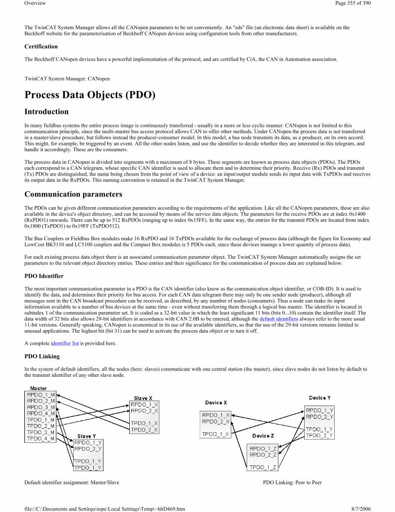
The TwinCAT System Manager allows all the CANopen parameters to be set conveniently. An "eds" file (an electronic data sheet) is available on the Beckhoff website for the parameterisation of Beckhoff CANopen devices using configuration tools from other manufacturers.
Certification
The Beckhoff CANopen devices have a powerful implementation of the protocol, and are certified by CiA, the CAN in Automation association.
Process Data Objects (PDO) Introduction In many fieldbus systems the entire process image is continuously transferred - usually in a more or less cyclic manner. CANopen is not limited to this communication principle, since the multi-master bus access protocol allows CAN to offer other methods. Under CANopen the process data is not transferred in a master/slave procedure, but follows instead the producer-consumer model. In this model, a bus node transmits its data, as a producer, on its own accord. This might, for example, be triggered by an event. All the other nodes listen, and use the identifier to decide whether they are interested in this telegram, and handle it accordingly. These are the consumers.
The process data in CANopen is divided into segments with a maximum of 8 bytes. These segments are known as process data objects (PDOs). The PDOs each correspond to a CAN telegram, whose specific CAN identifier is used to allocate them and to determine their priority. Receive (Rx) PDOs and transmit (Tx) PDOs are distinguished, the name being chosen from the point of view of a device: an input/output module sends its input data with TxPDOs and receives its output data in the RxPDOs. This naming convention is retained in the TwinCAT System Manager.
Communication parameters The PDOs can be given different communication parameters according to the requirements of the application. Like all the CANopen parameters, these are also available in the device's object directory, and can be accessed by means of the service data objects. The parameters for the receive PDOs are at index 0x1400 (RxPDO1) onwards. There can be up to 512 RxPDOs (ranging up to index 0x15FF). In the same way, the entries for the transmit PDOs are located from index 0x1800 (TxPDO1) to 0x19FF (TxPDO512).
The Bus Couplers or Fieldbus Box modules make 16 RxPDO and 16 TxPDOs available for the exchange of process data (although the figure for Economy and LowCost BK5110 and LC5100 couplers and the Compact Box modules is 5 PDOs each, since these devices manage a lower quantity of process data).
For each existing process data object there is an associated communication parameter object. The TwinCAT System Manager automatically assigns the set parameters to the relevant object directory entries. These entries and their significance for the communication of process data are explained below.
PDO Identifier
The most important communication parameter in a PDO is the CAN identifier (also know as the communication object identifier, or COB-ID). It is used to identify the data, and determines their priority for bus access. For each CAN data telegram there may only be one sender node (producer), although all messages sent in the CAN broadcast procedure can be received, as described, by any number of nodes (consumers). Thus a node can make its input information available to a number of bus devices at the same time - even without transferring them through a logical bus master. The identifier is located in subindex 1 of the communication parameter set. It is coded as a 32-bit value in which the least significant 11 bits (bits 0...10) contain the identifier itself. The data width of 32 bits also allows 29-bit identifiers in accordance with CAN 2.0B to be entered, although the default identifiers always refer to the more usual 11-bit versions. Generally speaking, CANopen is economical in its use of the available identifiers, so that the use of the 29-bit versions remains limited to unusual applications. The highest bit (bit 31) can be used to activate the process data object or to turn it off.
A complete identifier list is provided here.
PDO Linking
In the system of default identifiers, all the nodes (here: slaves) communicate with one central station (the master), since slave nodes do not listen by default to the transmit identifier of any other slave node.
Default identifier assignment: Master/Slave PDO Linking: Peer to Peer
TwinCAT System Manager: CANopen
Page 355 of 390Overview
8/7/2006file://C:\Documents and Settings\tope\Local Settings\Temp\~hhD469.htm

If the consumer-producer model of CANopen PDOs is to be used for direct data exchange between nodes (without a master), the distribution of identifiers must be appropriately adapted, so that the TxPDO identifier of the producer agrees with the RxPDO identifier of the consumer. This procedure is known as PDO linking. It permits, for example, easy construction of electronic drives in which several slave axes simultaneously listen to the actual value in the master axis TxPDO.
PDO Communication Types: Outline
CANopen offers a number of possible ways to transmit process data (see also: Notes on PDO Parameterisation).
.
Event driven
The ”event” is the alteration of an input value, the data being transmitted immediately after this change. The event-driven flow can make optimal use of the bus bandwidth, since instead of the whole process image it is only the changes in it that are transmitted. A short reaction time is achieved at the same time, since when an input value changes it is not necessary to wait for the next interrogation from a master.
Polled
The PDOs can also be polled by data request telegrams (remote frames). In this way it is possible to get the input process image of event-driven inputs onto the bus, even when they do not change, for instance through a monitoring or diagnostic device brought into the network while it is running. The time behaviour of remote frame and answer telegrams depends on what CAN controller is in use (Fig. 8). Components with full integrated message filtering ("FullCAN") usually answer a data request telegram immediately, transmitting data that is waiting in the appropriate transmit buffer - it is the responsibility of the application to see that the data there is continuously updated. CAN controllers with simple message filtering ("BasicCAN") on the other hand pass the request on to the application which can now compose the telegram with the latest data. This does take longer, but does mean that the data is "fresh". Beckhoff use CAN controllers following the principle of Basic CAN.
Since this device behaviour is usually not transparent to the user, and because there are CAN controllers still in use that do not support remote frames at all, polled communication can only with reservation be recommended for operative running.
Synchronised
It is not only for drive applications that it is worthwhile to synchronise the determination of the input information and the setting the outputs. For this purpose CANopen provides the SYNC object, a CAN telegram of high priority but containing no user data, whose reception is used by the synchronised nodes as a trigger for reading the inputs or for setting the outputs.
Page 356 of 390Overview
8/7/2006file://C:\Documents and Settings\tope\Local Settings\Temp\~hhD469.htm

PDO transmission types: Parameterisation
The PDO transmission type parameter specifies how the transmission of the PDO is triggered, or how received PDOs are handled.
Acyclic Synchronous
PDOs of transmission type 0 function synchronously, but not cyclically. An RxPDO is only evaluated after the next SYNC telegram has been received. In this way, for instance, axis groups can be given new target positions one after another, but these positions only become valid at the next SYNC - without the need to be constantly outputting reference points. A device whose TxPDO is configured for transmission type 0 acquires its input data when it receives the SYNC (synchronous process image) and then transmits it if the data correspond to an event (such as a change in input) having occurred. Transmission type 0 thus combines transmission for reasons that are event driven with a time for transmission (and, as far as possible, sampling) and processing given by the reception of "SYNC".
Cyclic Synchronous
In transmission types 1-240 the PDO is transmitted cyclically: after every ”nth” SYNC (n = 1...240). Since transmission types can be combined on a device as well as in the network, it is possible, for example, for a fast cycle to be agreed for digital inputs (n = 1), whereas the data for analog inputs is transmitted in a slower cycle (e.g. n = 10). RxPDOs do not generally distinguish between transmission types 0...240: a PDO that has been received is set to valid when the next SYNC is received. The cycle time (SYNC rate) can be monitored (object 0x1006), so that if the SYNC fails the device reacts in accordance with the definition in the device profile, and switches, for example, its outputs into the fault state.
The CANopen CIFx0 PC cards always transmit under event control, even if the transmission type is set in the range from 1-240. This behaviour is quite similar to transmission type 0. The FC510x PC cards support cyclic synchronous transmission types completely.
Only RTR
Transmission types 252 and 253 apply to process data objects that are transmitted exclusively on request by a remote frame. 252 is synchronous: when the SYNC is received the process data is acquired. It is only transmitted on request. 253 is asynchronous. The data here is acquired continuously, and transmitted on request. This type of transmission is not supported by the Beckhoff PC cards.
Asynchronous
The transmission types 254 + 255 are asynchronous, but may also be event-driven. In transmission type 254, the event is specific to the manufacturer, whereas for type 255 it is defined in the device profile. In the simplest case, the event is the change of an input value - this means that every change in the value is transmitted.
Transmission type Cyclical Acyclical Synchronous Asynchronous Only RTR 0 X X
1-240 X X 241-251 - reserved -
252 X X 253 X X
254, 255 X
Page 357 of 390Overview
8/7/2006file://C:\Documents and Settings\tope\Local Settings\Temp\~hhD469.htm

Inhibit time
The ”inhibit time” parameter can be used to implement a ”transmit filter” that does not increase the reaction time for relatively new input alterations, but is active for changes that follow immediately afterwards. The inhibit time (transmit delay time) specifies the minimum length of time that must be allowed to elapse between the transmission of two of the same telegrams. If the inhibit time is used, the maximum bus loading can be determined, so that the worst case latency can then be found.
Although the Beckhoff FC510x PC cards can parameterise the inhibit time on slave devices, they do not themselves support it. The transmitted PDOs become automatically spread out (transmit delay) as a result of the selected PLC cycle time - and there is little value in having the PLC run faster than the bus bandwidth permits. The bus loading, furthermore, can be significantly affected by the synchronous communication.
Event Timer
An event timer for transmit PDOs can be specified by subindex 5 in the communication parameters. Expiry of this timer is treated as an additional event for the corresponding PDO, so that the PDO will then be transmitted. If the application event occurs during a timer period, it will also be transmitted, and the timer is reset.
In the case of receive PDOs, the timer is used to set a watchdog interval for the PDO: the application is informed if no corresponding PDO has been received within the set period.
Notes on PDO Parameterisation
PDO Mapping PDO mapping refers to mapping of the application objects (real time data) from the object directory to the process data objects. The CANopen device profile provide a default mapping for every device type, and this is appropriate for most applications. Thus the default mapping for digital I/O simply represents the inputs and outputs in their physical sequence in the transmit and receive process data objects.
The first 4 analog inputs or outputs are located in the second PDO. These PDOs are accordingly occupied by the Beckhoff fieldbus I/O modules - if, for instance, no digital outputs are present, RxPDO1 remains empty.
In this way the PDO assignment for the Compact Box Modules is determined by the particular signal variants: digital input/output data is in PDO1, analog in PDO2, special signals in PDO3.
The extendable I/O modules occupy the PDOs automatically: during the start-up phase the coupler reads in which terminals are plugged in and which Extension Box Modules are present, and allocates the data to the PDOs. A distinction is made here between digital, analog and special terminals, and the PDOs are each occupied with one type. In other words, different types of data (such as digital and analog inputs) are not packed into one PDO, but a new PDO is started for each new data type.
Automatic PDO Assignment in Beckhoff Bus Couplers
The default PDOs for drives contain 2 bytes each of a control and status word and a set or actual value for the relevant axis.
The current mapping can be read by means of corresponding entries in the object directory. These are known as the mapping tables. The first location in the mapping table (sub-index 0) contains the number of mapped objects that are listed after it. The tables are located in the object directory at index 0x1600ff for the RxPDOs and at 0x1A00ff for the TxPDOs.
Page 358 of 390Overview
8/7/2006file://C:\Documents and Settings\tope\Local Settings\Temp\~hhD469.htm

Dummy Mapping
A further feature of CANopen is the mapping of placeholders, or dummy entries. The data type entries stored in the object directory, which do not themselves have data, are used as placeholders. If such entries are contained in the mapping table, the corresponding data from the device is not evaluated. In this way, for instance, a number of drives can be supplied with new set values using a single CAN telegram, or outputs on a number of nodes can be set simultaneously, even in event-driven mode.
PDO Parameterisation Even though the majority of CANopen networks operate satisfactorily with the default settings, i.e. with the minimum of configuration effort, it is wise at least to check whether the existing bus loading is reasonable: 80% bus loading may be acceptable for a network operating purely in cyclic synchronous modes, but for a network with event-driven traffic this value would generally be too high, as there is hardly any bandwidth available for additional events.
Consider the Requirements of the Application The communication of the process data must be optimised in the light of application requirements which are likely to be to some extent in conflict. These include
� Little work on parameterisation - useable default values are optimal � Guaranteed reaction time for specific events � Cycle time for regulation processes over the bus � Safety reserves for bus malfunctions (enough bandwidth for the repetition of messages) � Maximum baud rate - depends on the maximum bus length � Desired communication paths - who is speaking with whom
The determining factor often turns out to be the available bus bandwidth (bus load).
Baud rate
We generally begin by choosing the highest baud rate that the bus will permit. It should be borne in mind that serial bus systems are always more sensitive to interference at higher baud rates, so the better rule is "just as fast as needed". 1000 kbit/s are not usually necessary, and only to be unreservedly recommended on networks within a control cabinet where there is no electrical isolation between the bus nodes. Experience also tends to show that estimates of the length of bus cable laid are often over-optimistic - the length actually laid tends to be longer.
Determine the Communication Type
Once the baud rate has been chosen it is appropriate to specify the PDO communication type(s). These have different advantages and disadvantages:
� Cyclic synchronous communication provides an accurately predictable bus loading, and therefore a defined time behaviour - you could say that the standard case is the worst case. It is easy to configure: The SYNC rate parameter sets the bus loading globally. The process images are synchronised: Inputs are read at the same time, output data is set valid simultaneously, although the quality of the synchronisation depends on the implementation. The Beckhoff FC510x PC cards are capable of synchronising the CANopen bus system with the cycles of the application program (PLC or NC). The guaranteed reaction time under cyclic synchronous communication is always at least as long as the cycle time, and the bus bandwidth is not exploited optimally, since "old" data, i.e. data that has not changed, is continuously transmitted. It is however possible to optimise the network through the selection of different SYNC multiples (transmission types 1...240), so that data that changes slowly is transmitted less often than, for instance, time-critical inputs. It must, however, be borne in mind that input states that last for a time that is shorter than the cycle time will not necessarily be communicated. If it is necessary for such conditions to be registered, the associated PDOs for asynchronous communication should be provided.
� Event-driven asynchronous communication is optimal from the point of view of reaction time and the exploitation of bus bandwidth - it can be described as "pure CAN". Your choice must, however, also take account of the fact that it is not impossible for a large number of events to occur simultaneously, leading to corresponding delays before a PDO with a relatively low priority can be sent. Proper network planning therefore necessitates a worst-case analysis. Through the use of, for instance, inhibit time, it is also necessary to prevent a constantly changing input with a high PDO priority from blocking the bus (technically known as a "babbling idiot"). It is for this reason that event driving is switched off by default in the device profile of analog inputs, and must be turned on specifically. Time windows for the transmit PDOs can be set using progress timers: the telegram is not sent again before the inhibit time has elapsed, and not later than the time required for the progress timer to complete.
� The communication type is parameterised by means of the transmission type.
TwinCAT System Manager: CANopen
Page 359 of 390Overview
8/7/2006file://C:\Documents and Settings\tope\Local Settings\Temp\~hhD469.htm

It is also possible to combine the two PDO principles. It can, for instance, be helpful to exchange the set and actual values of an axis controller synchronously, while limit switches, or motor temperatures with limit values are monitored with event-driven PDOs. This combines the advantages of the two principles: synchronicity for the axis communication and short reaction times for limit switches. In spite of being event-driven, the distributed limit value monitoring avoids a constant addition to the bus load from the analog temperature value.
In this example it can also be of value to deliberately manipulate the identifier allocation, in order to optimise bus access by means of priority allocation: the highest priority is given to the PDO with the limit switch data, and the lowest to that with the temperature values.
Optimisation of bus access latency time through modification of the identifier allocation is not, however, normally required. On the other hand the identifiers must be altered if "masterless" communication is to be made possible (PDO linking). In this example it would be possible for one RxPDO for each axis to be allocated the same identifier as the limit switch TxPDO, so that alterations of the input value can be received without delay.
Determining the Bus Loading
It is always worth determining the bus loading. But what bus loading values are "permitted", or indeed sensible? It is first necessary to distinguish a short burst of telegrams in which a number of CAN messages follow one another immediately - a temporary 100% bus loading. This is only a problem if the sequence of receive interrupts that it caused at the CAN nodes can not be handled. This would constitute a data overflow (or "CAN queue overrun"). This can occur at very high baud rates (> 500 kbit/s) at nodes with software telegram filtering and relatively slow or heavily loaded microcontrollers if, for instance, a series of remote frames (which do not contain data bytes, and are therefore very short) follow each other closely on the bus (at 1 Mbit/s this can generate an interrupt every 40 µs; for example, an NMT master might transmit all its guarding requests in an unbroken sequence). This can be avoided through skilled implementation, and the user should be able to assume that the device suppliers have taken the necessary trouble. A burst condition is entirely normal immediately after the SYNC telegram, for instance: triggered by the SYNC, all the nodes that are operating synchronously try to send their data at almost the same time. A large number of arbitration processes take place, and the telegrams are sorted in order of priority for transmission on the bus. This is not usually critical, since these telegrams do contain some data bytes, and the telegrams trigger a sequence of receive interrupts at the CAN nodes which is indeed rapid, but is nevertheless manageable.
Bus loading most often refers to the value averaged over several primary cycles, that is the mean value over 100-500 ms. CAN, and therefore CANopen, is indeed capable of managing a bus loading of close to 100% over long periods, but this implies that no bandwidth is available for any repetitions that may be necessitated by interference, for asynchronous error messages, parameterisation and so on. Clearly, the dominant type of communication will have a large influence on the appropriate level of bus loading: a network with entirely cyclic synchronous operation is always in any case near to the "worst case" state, and can therefore be operated with values in the 70-80% range. The figure is very hard to state for an entirely event-driven network: an estimate must be made of how many events additional to the current state of the system might occur, and of how long the resulting burst might last - in other words, for how long the lowest priority message will be delayed. If this value is acceptable to the application, then the current bus loading is acceptable. As a rule of thumb it can usually be assumed that an event-driven network running with a base loading of 30-40% has enough reserve for worst-case scenarios, but this assumption does not obviate the need for a careful analysis if delays could have critical results for the plant.
The Beckhoff FC510x PC cards indicate the bus loading via the System Manager. This variable can also be processed in the PLC, or can be displayed in the visualisation system.
The amount data in the process data objects is of course as relevant as the communication parameters: the PDO mapping.
Page 360 of 390Overview
8/7/2006file://C:\Documents and Settings\tope\Local Settings\Temp\~hhD469.htm

Automatic PDO Mapping BK51x0, IL23x0-B510 PDO1 and PDO2 are occupied, as described, with digital and analog process data. For each additional PDO the CANopen node acts in accordance with the following procedure, and puts process data into the PDOs in the following sequence:
1. Digital I/Os (if more than 64 are present)
2. 1-bytes special terminals
3. Analog I/Os
4. 2-bytes special terminals
5. 3-bytes special terminals
6. ...10. 8-bytes special terminals
Data types are not mixed, and a new PDO is taken for each new data type. for example
The procedure is illustrated in the flow diagram below.
Example
TwinCAT System Manager: CANopen
Page 361 of 390Overview
8/7/2006file://C:\Documents and Settings\tope\Local Settings\Temp\~hhD469.htm
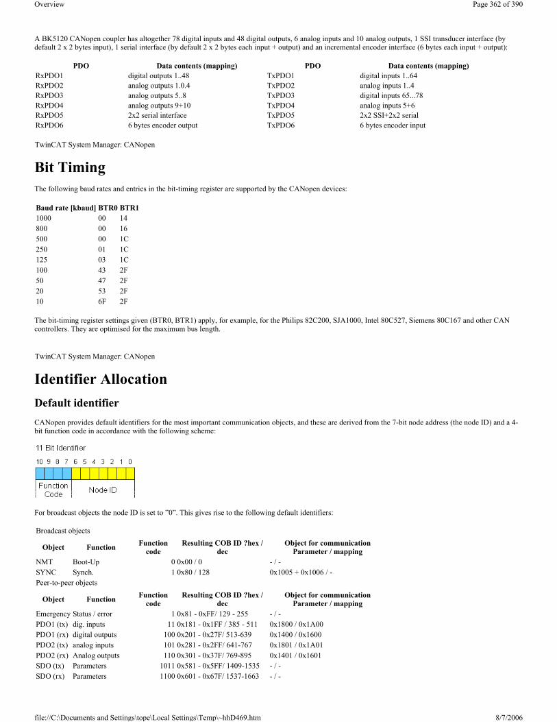
A BK5120 CANopen coupler has altogether 78 digital inputs and 48 digital outputs, 6 analog inputs and 10 analog outputs, 1 SSI transducer interface (by default 2 x 2 bytes input), 1 serial interface (by default 2 x 2 bytes each input + output) and an incremental encoder interface (6 bytes each input + output):
Bit Timing The following baud rates and entries in the bit-timing register are supported by the CANopen devices:
The bit-timing register settings given (BTR0, BTR1) apply, for example, for the Philips 82C200, SJA1000, Intel 80C527, Siemens 80C167 and other CAN controllers. They are optimised for the maximum bus length.
Identifier Allocation Default identifier CANopen provides default identifiers for the most important communication objects, and these are derived from the 7-bit node address (the node ID) and a 4-bit function code in accordance with the following scheme:
For broadcast objects the node ID is set to ”0”. This gives rise to the following default identifiers:
PDO Data contents (mapping) PDO Data contents (mapping)RxPDO1 digital outputs 1..48 TxPDO1 digital inputs 1..64 RxPDO2 analog outputs 1.0.4 TxPDO2 analog inputs 1..4 RxPDO3 analog outputs 5..8 TxPDO3 digital inputs 65...78 RxPDO4 analog outputs 9+10 TxPDO4 analog inputs 5+6 RxPDO5 2x2 serial interface TxPDO5 2x2 SSI+2x2 serial RxPDO6 6 bytes encoder output TxPDO6 6 bytes encoder input TwinCAT System Manager: CANopen
Baud rate [kbaud] BTR0 BTR11000 00 14800 00 16 500 00 1C 250 01 1C 125 03 1C 100 43 2F50 47 2F 20 53 2F 10 6F 2F
TwinCAT System Manager: CANopen
Broadcast objects
Object Function Function code
Resulting COB ID ?hex / dec
Object for communication Parameter / mapping
NMT Boot-Up 0 0x00 / 0 - / -SYNC Synch. 1 0x80 / 128 0x1005 + 0x1006 / -Peer-to-peer objects
Object Function Function code
Resulting COB ID ?hex / dec
Object for communication Parameter / mapping
Emergency Status / error 1 0x81 - 0xFF/ 129 - 255 - / -PDO1 (tx) dig. inputs 11 0x181 - 0x1FF / 385 - 511 0x1800 / 0x1A00PDO1 (rx) digital outputs 100 0x201 - 0x27F/ 513-639 0x1400 / 0x1600PDO2 (tx) analog inputs 101 0x281 - 0x2FF/ 641-767 0x1801 / 0x1A01PDO2 (rx) Analog outputs 110 0x301 - 0x37F/ 769-895 0x1401 / 0x1601SDO (tx) Parameters 1011 0x581 - 0x5FF/ 1409-1535 - / -SDO (rx) Parameters 1100 0x601 - 0x67F/ 1537-1663 - / -
Page 362 of 390Overview
8/7/2006file://C:\Documents and Settings\tope\Local Settings\Temp\~hhD469.htm

Note: Up until version 3 of the CANopen specification, default identifiers were assigned to 2 PDOs at a time. The Beckhoff Bus Couplers correspond to this issue of the specification. After version 4, default identifiers are provided for up to 4 PDOs.
Manufacture-Specific Default Identifiers for Additional PDOs Identifiers are not assigned to the additional PDOs that are filled by the Beckhoff Bus Couplers in accordance with the standard scheme. The user must enter an identifier for these PDOs in the object directory. It is easier to activate the occupied PDOs by means of object 0x5500.
This entry in the object directory extends the allocation of default identifiers up to 11 PDOs. This creates the following identifiers:
Remark: Ensure that index 0x5500 is not used if bus couplers with more than 5 PDOs are present in networks with node numbers >64, otherwise identification overlaps can occur.
Identifier Full List Identifiers marked with * are given manufacturer-specific assignments on the bus couplers after writing index 0x5500
0x201 0x301 0x401 0x501 0x601 0x701
Guarding Life/node guarding 1110 0x701 - 0x77F/ 1793-1919 (0x100C, 0x100D, 0x100E)
Object Function code
Resulting COB ID (hex) Resulting COB ID (dec)
PDO3 (tx) 111 0x381 - 0x3BF 897 - 959PDO3 (rx) 1000 0x401 - 0x43F 1025 - 1087PDO4 (tx) 1001 0x481 - 0x4BF 1153 - 1215PDO4 (rx) 1010 0x501 - 0x53F 1281- 1343PDO5 (tx) 1101 0x681 - 0x6BF 1665 - 1727PDO5 (rx) 1111 0x781 - 0x7BF 1921- 1983PDO6 (tx) 111 0x1C1 - 0x1FF 449 - 511PDO6 (rx) 1001 0x241 - 0x27F 577 - 639PDO7 (tx) 1011 0x2C1 - 0x2FF 705 - 767PDO7 (rx) 1101 0x341 - 0x37F 833 - 895PDO8 (tx) 1111 0x3C1- 0x3FF 961 - 1023PDO8 (rx) 10001 0x441 - 0x47F 1089 - 1151PDO9 (tx) 10011 0x4C1 - 0x4FF 1217 - 1279PDO9 (rx) 10101 0x541 - 0x57F 1345 - 1407PDO10 (tx) 10111 0x5C1 - 0x5FF 1473 - 1535
PDO10 (rx) 11001 0x641 - 0x67F 1601- 1663
PDO11 (tx) 11011 0x6C1 - 0x6FF 1729 - 1791
PDO11 (rx) 11101 0x741 - 0x77F 1857 - 1919
TwinCAT System Manager: CANopen
dec hex Meaning dec hex Meaning dec hex Meaning0 0 NMT 874 36A RxPDO7*, Nd.42 1430 596 SDO Tx Nd.22128 80 SYNC 875 36B RxPDO7*, Nd.43 1431 597 SDO Tx Nd.23129 81 EMCY Nd.1 876 36C RxPDO7*, Nd.44 1432 598 SDO Tx Nd.24130 82 EMCY Nd.2 877 36D RxPDO7*, Nd.45 1433 599 SDO Tx Nd.25131 83 EMCY Nd.3 878 36E RxPDO7*, Nd.46 1434 59A SDO Tx Nd.26132 84 EMCY Nd.4 879 36F RxPDO7*, Nd.47 1435 59B SDO Tx Nd.27133 85 EMCY Nd.5 880 370 RxPDO7*, Nd.48 1436 59C SDO Tx Nd.28134 86 EMCY Nd.6 881 371 RxPDO7*, Nd.49 1437 59D SDO Tx Nd.29
Page 363 of 390Overview
8/7/2006file://C:\Documents and Settings\tope\Local Settings\Temp\~hhD469.htm

135 87 EMCY Nd.7 882 372 RxPDO7*, Nd.50 1438 59E SDO Tx Nd.30136 88 EMCY Nd.8 883 373 RxPDO7*, Nd.51 1439 59F SDO Tx Nd.31137 89 EMCY Nd.9 884 374 RxPDO7*, Nd.52 1440 5A0 SDO Tx Nd.32138 8A EMCY Nd.10 885 375 RxPDO7*, Nd.53 1441 5A1 SDO Tx Nd.33139 8B EMCY Nd.11 886 376 RxPDO7*, Nd.54 1442 5A2 SDO Tx Nd.34140 8C EMCY Nd.12 887 377 RxPDO7*, Nd.55 1443 5A3 SDO Tx Nd.35141 8D EMCY Nd.13 888 378 RxPDO7*, Nd.56 1444 5A4 SDO Tx Nd.36142 8E EMCY Nd.14 889 379 RxPDO7*, Nd.57 1445 5A5 SDO Tx Nd.37143 8F EMCY Nd.15 890 37A RxPDO7*, Nd.58 1446 5A6 SDO Tx Nd.38144 90 EMCY Nd.16 891 37B RxPDO7*, Nd.59 1447 5A7 SDO Tx Nd.39145 91 EMCY Nd.17 892 37C RxPDO7*, Nd.60 1448 5A8 SDO Tx Nd.40146 92 EMCY Nd.18 893 37D RxPDO7*, Nd.61 1449 5A9 SDO Tx Nd.41147 93 EMCY Nd.19 894 37E RxPDO7*, Nd.62 1450 5AA SDO Tx Nd.42148 94 EMCY Nd.20 895 37F RxPDO7*, Nd.63 1451 5AB SDO Tx Nd.43149 95 EMCY Nd.21 897 381 TxPDO3*, Nd.1 1452 5AC SDO Tx Nd.44150 96 EMCY Nd.22 898 382 TxPDO3*, Nd.2 1453 5AD SDO Tx Nd.45151 97 EMCY Nd.23 899 383 TxPDO3*, Nd.3 1454 5AE SDO Tx Nd.46152 98 EMCY Nd.24 900 384 TxPDO3*, Nd.4 1455 5AF SDO Tx Nd.47153 99 EMCY Nd.25 901 385 TxPDO3*, Nd.5 1456 5B0 SDO Tx Nd.48154 9A EMCY Nd.26 902 386 TxPDO3*, Nd.6 1457 5B1 SDO Tx Nd.49155 9B EMCY Nd.27 903 387 TxPDO3*, Nd.7 1458 5B2 SDO Tx Nd.50156 9C EMCY Nd.28 904 388 TxPDO3*, Nd.8 1459 5B3 SDO Tx Nd.51157 9D EMCY Nd.29 905 389 TxPDO3*, Nd.9 1460 5B4 SDO Tx Nd.52158 9E EMCY Nd.30 906 38A TxPDO3*, Nd.10 1461 5B5 SDO Tx Nd.53159 9F EMCY Nd.31 907 38B TxPDO3*, Nd.11 1462 5B6 SDO Tx Nd.54160 A0 EMCY Nd.32 908 38C TxPDO3*, Nd.12 1463 5B7 SDO Tx Nd.55161 A1 EMCY Nd.33 909 38D TxPDO3*, Nd.13 1464 5B8 SDO Tx Nd.56162 A2 EMCY Nd.34 910 38E TxPDO3*, Nd.14 1465 5B9 SDO Tx Nd.57163 A3 EMCY Nd.35 911 38F TxPDO3*, Nd.15 1466 5BA SDO Tx Nd.58164 A4 EMCY Nd.36 912 390 TxPDO3*, Nd.16 1467 5BB SDO Tx Nd.59165 A5 EMCY Nd.37 913 391 TxPDO3*, Nd.17 1468 5BC SDO Tx Nd.60166 A6 EMCY Nd.38 914 392 TxPDO3*, Nd.18 1469 5BD SDO Tx Nd.61167 A7 EMCY Nd.39 915 393 TxPDO3*, Nd.19 1470 5BE SDO Tx Nd.62168 A8 EMCY Nd.40 916 394 TxPDO3*, Nd.20 1471 5BF SDO Tx Nd.63169 A9 EMCY Nd.41 917 395 TxPDO3*, Nd.21 1473 5C1 TxPDO10*, Nd.1170 AA EMCY Nd.42 918 396 TxPDO3*, Nd.22 1474 5C2 TxPDO10*, Nd.2171 AB EMCY Nd.43 919 397 TxPDO3*, Nd.23 1475 5C3 TxPDO10*, Nd.3172 AC EMCY Nd.44 920 398 TxPDO3*, Nd.24 1476 5C4 TxPDO10*, Nd.4173 AD EMCY Nd.45 921 399 TxPDO3*, Nd.25 1477 5C5 TxPDO10*, Nd.5174 AE EMCY Nd.46 922 39A TxPDO3*, Nd.26 1478 5C6 TxPDO10*, Nd.6175 AF EMCY Nd.47 923 39B TxPDO3*, Nd.27 1479 5C7 TxPDO10*, Nd.7176 B0 EMCY Nd.48 924 39C TxPDO3*, Nd.28 1480 5C8 TxPDO10*, Nd.8177 B1 EMCY Nd.49 925 39D TxPDO3*, Nd.29 1481 5C9 TxPDO10*, Nd.9178 B2 EMCY Nd.50 926 39E TxPDO3*, Nd.30 1482 5CA TxPDO10*, Nd.10179 B3 EMCY Nd.51 927 39F TxPDO3*, Nd.31 1483 5CB TxPDO10*, Nd.11180 B4 EMCY Nd.52 928 3A0 TxPDO3*, Nd.32 1484 5CC TxPDO10*, Nd.12181 B5 EMCY Nd.53 929 3A1 TxPDO3*, Nd.33 1485 5CD TxPDO10*, Nd.13182 B6 EMCY Nd.54 930 3A2 TxPDO3*, Nd.34 1486 5CE TxPDO10*, Nd.14183 B7 EMCY Nd.55 931 3A3 TxPDO3*, Nd.35 1487 5CF TxPDO10*, Nd.15184 B8 EMCY Nd.56 932 3A4 TxPDO3*, Nd.36 1488 5D0 TxPDO10*, Nd.16185 B9 EMCY Nd.57 933 3A5 TxPDO3*, Nd.37 1489 5D1 TxPDO10*, Nd.17186 BA EMCY Nd.58 934 3A6 TxPDO3*, Nd.38 1490 5D2 TxPDO10*, Nd.18187 BB EMCY Nd.59 935 3A7 TxPDO3*, Nd.39 1491 5D3 TxPDO10*, Nd.19188 BC EMCY Nd.60 936 3A8 TxPDO3*, Nd.40 1492 5D4 TxPDO10*, Nd.20189 BD EMCY Nd.61 937 3A9 TxPDO3*, Nd.41 1493 5D5 TxPDO10*, Nd.21190 BE EMCY Nd.62 938 3AA TxPDO3*, Nd.42 1494 5D6 TxPDO10*, Nd.22191 BF EMCY Nd.63 939 3AB TxPDO3*, Nd.43 1495 5D7 TxPDO10*, Nd.23385 181 TxPDO1, DI, Nd.1 940 3AC TxPDO3*, Nd.44 1496 5D8 TxPDO10*, Nd.24386 182 TxPDO1, DI, Nd.2 941 3AD TxPDO3*, Nd.45 1497 5D9 TxPDO10*, Nd.25387 183 TxPDO1, DI, Nd.3 942 3AE TxPDO3*, Nd.46 1498 5DA TxPDO10*, Nd.26388 184 TxPDO1, DI, Nd.4 943 3AF TxPDO3*, Nd.47 1499 5DB TxPDO10*, Nd.27389 185 TxPDO1, DI, Nd.5 944 3B0 TxPDO3*, Nd.48 1500 5DC TxPDO10*, Nd.28
Page 364 of 390Overview
8/7/2006file://C:\Documents and Settings\tope\Local Settings\Temp\~hhD469.htm

390 186 TxPDO1, DI, Nd.6 945 3B1 TxPDO3*, Nd.49 1501 5DD TxPDO10*, Nd.29391 187 TxPDO1, DI, Nd.7 946 3B2 TxPDO3*, Nd.50 1502 5DE TxPDO10*, Nd.30392 188 TxPDO1, DI, Nd.8 947 3B3 TxPDO3*, Nd.51 1503 5DF TxPDO10*, Nd.31393 189 TxPDO1, DI, Nd.9 948 3B4 TxPDO3*, Nd.52 1504 5E0 TxPDO10*, Nd.32394 18A TxPDO1, DI, Nd.10 949 3B5 TxPDO3*, Nd.53 1505 5E1 TxPDO10*, Nd.33395 18B TxPDO1, DI, Nd.11 950 3B6 TxPDO3*, Nd.54 1506 5E2 TxPDO10*, Nd.34396 18C TxPDO1, DI, Nd.12 951 3B7 TxPDO3*, Nd.55 1507 5E3 TxPDO10*, Nd.35397 18D TxPDO1, DI, Nd.13 952 3B8 TxPDO3*, Nd.56 1508 5E4 TxPDO10*, Nd.36398 18E TxPDO1, DI, Nd.14 953 3B9 TxPDO3*, Nd.57 1509 5E5 TxPDO10*, Nd.37399 18F TxPDO1, DI, Nd.15 954 3BA TxPDO3*, Nd.58 1510 5E6 TxPDO10*, Nd.38400 190 TxPDO1, DI, Nd.16 955 3BB TxPDO3*, Nd.59 1511 5E7 TxPDO10*, Nd.39401 191 TxPDO1, DI, Nd.17 956 3BC TxPDO3*, Nd.60 1512 5E8 TxPDO10*, Nd.40402 192 TxPDO1, DI, Nd.18 957 3BD TxPDO3*, Nd.61 1513 5E9 TxPDO10*, Nd.41403 193 TxPDO1, DI, Nd.19 958 3BE TxPDO3*, Nd.62 1514 5EA TxPDO10*, Nd.42404 194 TxPDO1, DI, Nd.20 959 3BF TxPDO3*, Nd.63 1515 5EB TxPDO10*, Nd.43405 195 TxPDO1, DI, Nd.21 961 3C1 TxPDO8*, Nd.1 1516 5EC TxPDO10*, Nd.44406 196 TxPDO1, DI, Nd.22 962 3C2 TxPDO8*, Nd.2 1517 5ED TxPDO10*, Nd.45407 197 TxPDO1, DI, Nd.23 963 3C3 TxPDO8*, Nd.3 1518 5EE TxPDO10*, Nd.46408 198 TxPDO1, DI, Nd.24 964 3C4 TxPDO8*, Nd.4 1519 5EF TxPDO10*, Nd.47409 199 TxPDO1, DI, Nd.25 965 3C5 TxPDO8*, Nd.5 1520 5F0 TxPDO10*, Nd.48410 19A TxPDO1, DI, Nd.26 966 3C6 TxPDO8*, Nd.6 1521 5F1 TxPDO10*, Nd.49411 19B TxPDO1, DI, Nd.27 967 3C7 TxPDO8*, Nd.7 1522 5F2 TxPDO10*, Nd.50412 19C TxPDO1, DI, Nd.28 968 3C8 TxPDO8*, Nd.8 1523 5F3 TxPDO10*, Nd.51413 19D TxPDO1, DI, Nd.29 969 3C9 TxPDO8*, Nd.9 1524 5F4 TxPDO10*, Nd.52414 19E TxPDO1, DI, Nd.30 970 3CA TxPDO8*, Nd.10 1525 5F5 TxPDO10*, Nd.53415 19F TxPDO1, DI, Nd.31 971 3CB TxPDO8*, Nd.11 1526 5F6 TxPDO10*, Nd.54416 1A0 TxPDO1, DI, Nd.32 972 3CC TxPDO8*, Nd.12 1527 5F7 TxPDO10*, Nd.55417 1A1 TxPDO1, DI, Nd.33 973 3CD TxPDO8*, Nd.13 1528 5F8 TxPDO10*, Nd.56418 1A2 TxPDO1, DI, Nd.34 974 3CE TxPDO8*, Nd.14 1529 5F9 TxPDO10*, Nd.57419 1A3 TxPDO1, DI, Nd.35 975 3CF TxPDO8*, Nd.15 1530 5FA TxPDO10*, Nd.58420 1A4 TxPDO1, DI, Nd.36 976 3D0 TxPDO8*, Nd.16 1531 5FB TxPDO10*, Nd.59421 1A5 TxPDO1, DI, Nd.37 977 3D1 TxPDO8*, Nd.17 1532 5FC TxPDO10*, Nd.60422 1A6 TxPDO1, DI, Nd.38 978 3D2 TxPDO8*, Nd.18 1533 5FD TxPDO10*, Nd.61423 1A7 TxPDO1, DI, Nd.39 979 3D3 TxPDO8*, Nd.19 1534 5FE TxPDO10*, Nd.62424 1A8 TxPDO1, DI, Nd.40 980 3D4 TxPDO8*, Nd.20 1535 5FF TxPDO10*, Nd.63425 1A9 TxPDO1, DI, Nd.41 981 3D5 TxPDO8*, Nd.21 1537 601 SDO Rx Nd.1426 1AA TxPDO1, DI, Nd.42 982 3D6 TxPDO8*, Nd.22 1538 602 SDO Rx Nd.2427 1AB TxPDO1, DI, Nd.43 983 3D7 TxPDO8*, Nd.23 1539 603 SDO Rx Nd.3428 1AC TxPDO1, DI, Nd.44 984 3D8 TxPDO8*, Nd.24 1540 604 SDO Rx Nd.4429 1AD TxPDO1, DI, Nd.45 985 3D9 TxPDO8*, Nd.25 1541 605 SDO Rx Nd.5430 1AE TxPDO1, DI, Nd.46 986 3DA TxPDO8*, Nd.26 1542 606 SDO Rx Nd.6431 1AF TxPDO1, DI, Nd.47 987 3DB TxPDO8*, Nd.27 1543 607 SDO Rx Nd.7432 1B0 TxPDO1, DI, Nd.48 988 3DC TxPDO8*, Nd.28 1544 608 SDO Rx Nd.8433 1B1 TxPDO1, DI, Nd.49 989 3DD TxPDO8*, Nd.29 1545 609 SDO Rx Nd.9434 1B2 TxPDO1, DI, Nd.50 990 3DE TxPDO8*, Nd.30 1546 60A SDO Rx Nd.10435 1B3 TxPDO1, DI, Nd.51 991 3DF TxPDO8*, Nd.31 1547 60B SDO Rx Nd.11436 1B4 TxPDO1, DI, Nd.52 992 3E0 TxPDO8*, Nd.32 1548 60C SDO Rx Nd.12437 1B5 TxPDO1, DI, Nd.53 993 3E1 TxPDO8*, Nd.33 1549 60D SDO Rx Nd.13438 1B6 TxPDO1, DI, Nd.54 994 3E2 TxPDO8*, Nd.34 1550 60E SDO Rx Nd.14439 1B7 TxPDO1, DI, Nd.55 995 3E3 TxPDO8*, Nd.35 1551 60F SDO Rx Nd.15440 1B8 TxPDO1, DI, Nd.56 996 3E4 TxPDO8*, Nd.36 1552 610 SDO Rx Nd.16441 1B9 TxPDO1, DI, Nd.57 997 3E5 TxPDO8*, Nd.37 1553 611 SDO Rx Nd.17442 1BA TxPDO1, DI, Nd.58 998 3E6 TxPDO8*, Nd.38 1554 612 SDO Rx Nd.18443 1BB TxPDO1, DI, Nd.59 999 3E7 TxPDO8*, Nd.39 1555 613 SDO Rx Nd.19444 1BC TxPDO1, DI, Nd.60 1000 3E8 TxPDO8*, Nd.40 1556 614 SDO Rx Nd.20445 1BD TxPDO1, DI, Nd.61 1001 3E9 TxPDO8*, Nd.41 1557 615 SDO Rx Nd.21446 1BE TxPDO1, DI, Nd.62 1002 3EA TxPDO8*, Nd.42 1558 616 SDO Rx Nd.22447 1BF TxPDO1, DI, Nd.63 1003 3EB TxPDO8*, Nd.43 1559 617 SDO Rx Nd.23449 1C1 TxPDO6*, Nd.1 1004 3EC TxPDO8*, Nd.44 1560 618 SDO Rx Nd.24450 1C2 TxPDO6*, Nd.2 1005 3ED TxPDO8*, Nd.45 1561 619 SDO Rx Nd.25451 1C3 TxPDO6*, Nd.3 1006 3EE TxPDO8*, Nd.46 1562 61A SDO Rx Nd.26452 1C4 TxPDO6*, Nd.4 1007 3EF TxPDO8*, Nd.47 1563 61B SDO Rx Nd.27
Page 365 of 390Overview
8/7/2006file://C:\Documents and Settings\tope\Local Settings\Temp\~hhD469.htm

453 1C5 TxPDO6*, Nd.5 1008 3F0 TxPDO8*, Nd.48 1564 61C SDO Rx Nd.28454 1C6 TxPDO6*, Nd.6 1009 3F1 TxPDO8*, Nd.49 1565 61D SDO Rx Nd.29455 1C7 TxPDO6*, Nd.7 1010 3F2 TxPDO8*, Nd.50 1566 61E SDO Rx Nd.30456 1C8 TxPDO6*, Nd.8 1011 3F3 TxPDO8*, Nd.51 1567 61F SDO Rx Nd.31457 1C9 TxPDO6*, Nd.9 1012 3F4 TxPDO8*, Nd.52 1568 620 SDO Rx Nd.32458 1CA TxPDO6*, Nd.10 1013 3F5 TxPDO8*, Nd.53 1569 621 SDO Rx Nd.33459 1CB TxPDO6*, Nd.11 1014 3F6 TxPDO8*, Nd.54 1570 622 SDO Rx Nd.34460 1CC TxPDO6*, Nd.12 1015 3F7 TxPDO8*, Nd.55 1571 623 SDO Rx Nd.35461 1CD TxPDO6*, Nd.13 1016 3F8 TxPDO8*, Nd.56 1572 624 SDO Rx Nd.36462 1CE TxPDO6*, Nd.14 1017 3F9 TxPDO8*, Nd.57 1573 625 SDO Rx Nd.37463 1CF TxPDO6*, Nd.15 1018 3FA TxPDO8*, Nd.58 1574 626 SDO Rx Nd.38464 1D0 TxPDO6*, Nd.16 1019 3FB TxPDO8*, Nd.59 1575 627 SDO Rx Nd.39465 1D1 TxPDO6*, Nd.17 1020 3FC TxPDO8*, Nd.60 1576 628 SDO Rx Nd.40466 1D2 TxPDO6*, Nd.18 1021 3FD TxPDO8*, Nd.61 1577 629 SDO Rx Nd.41467 1D3 TxPDO6*, Nd.19 1022 3FE TxPDO8*, Nd.62 1578 62A SDO Rx Nd.42468 1D4 TxPDO6*, Nd.20 1023 3FF TxPDO8*, Nd.63 1579 62B SDO Rx Nd.43469 1D5 TxPDO6*, Nd.21 1025 401 RxPDO3*, Nd.1 1580 62C SDO Rx Nd.44470 1D6 TxPDO6*, Nd.22 1026 402 RxPDO3*, Nd.2 1581 62D SDO Rx Nd.45471 1D7 TxPDO6*, Nd.23 1027 403 RxPDO3*, Nd.3 1582 62E SDO Rx Nd.46472 1D8 TxPDO6*, Nd.24 1028 404 RxPDO3*, Nd.4 1583 62F SDO Rx Nd.47473 1D9 TxPDO6*, Nd.25 1029 405 RxPDO3*, Nd.5 1584 630 SDO Rx Nd.48474 1DA TxPDO6*, Nd.26 1030 406 RxPDO3*, Nd.6 1585 631 SDO Rx Nd.49475 1DB TxPDO6*, Nd.27 1031 407 RxPDO3*, Nd.7 1586 632 SDO Rx Nd.50476 1DC TxPDO6*, Nd.28 1032 408 RxPDO3*, Nd.8 1587 633 SDO Rx Nd.51477 1DD TxPDO6*, Nd.29 1033 409 RxPDO3*, Nd.9 1588 634 SDO Rx Nd.52478 1DE TxPDO6*, Nd.30 1034 40A RxPDO3*, Nd.10 1589 635 SDO Rx Nd.53479 1DF TxPDO6*, Nd.31 1035 40B RxPDO3*, Nd.11 1590 636 SDO Rx Nd.54480 1E0 TxPDO6*, Nd.32 1036 40C RxPDO3*, Nd.12 1591 637 SDO Rx Nd.55481 1E1 TxPDO6*, Nd.33 1037 40D RxPDO3*, Nd.13 1592 638 SDO Rx Nd.56482 1E2 TxPDO6*, Nd.34 1038 40E RxPDO3*, Nd.14 1593 639 SDO Rx Nd.57483 1E3 TxPDO6*, Nd.35 1039 40F RxPDO3*, Nd.15 1594 63A SDO Rx Nd.58484 1E4 TxPDO6*, Nd.36 1040 410 RxPDO3*, Nd.16 1595 63B SDO Rx Nd.59485 1E5 TxPDO6*, Nd.37 1041 411 RxPDO3*, Nd.17 1596 63C SDO Rx Nd.60486 1E6 TxPDO6*, Nd.38 1042 412 RxPDO3*, Nd.18 1597 63D SDO Rx Nd.61487 1E7 TxPDO6*, Nd.39 1043 413 RxPDO3*, Nd.19 1598 63E SDO Rx Nd.62488 1E8 TxPDO6*, Nd.40 1044 414 RxPDO3*, Nd.20 1599 63F SDO Rx Nd.63489 1E9 TxPDO6*, Nd.41 1045 415 RxPDO3*, Nd.21 1601 641 RxPDO10*, Nd.1490 1EA TxPDO6*, Nd.42 1046 416 RxPDO3*, Nd.22 1602 642 RxPDO10*, Nd.2491 1EB TxPDO6*, Nd.43 1047 417 RxPDO3*, Nd.23 1603 643 RxPDO10*, Nd.3492 1EC TxPDO6*, Nd.44 1048 418 RxPDO3*, Nd.24 1604 644 RxPDO10*, Nd.4493 1ED TxPDO6*, Nd.45 1049 419 RxPDO3*, Nd.25 1605 645 RxPDO10*, Nd.5494 1EE TxPDO6*, Nd.46 1050 41A RxPDO3*, Nd.26 1606 646 RxPDO10*, Nd.6495 1EF TxPDO6*, Nd.47 1051 41B RxPDO3*, Nd.27 1607 647 RxPDO10*, Nd.7496 1F0 TxPDO6*, Nd.48 1052 41C RxPDO3*, Nd.28 1608 648 RxPDO10*, Nd.8497 1F1 TxPDO6*, Nd.49 1053 41D RxPDO3*, Nd.29 1609 649 RxPDO10*, Nd.9498 1F2 TxPDO6*, Nd.50 1054 41E RxPDO3*, Nd.30 1610 64A RxPDO10*, Nd.10499 1F3 TxPDO6*, Nd.51 1055 41F RxPDO3*, Nd.31 1611 64B RxPDO10*, Nd.11500 1F4 TxPDO6*, Nd.52 1056 420 RxPDO3*, Nd.32 1612 64C RxPDO10*, Nd.12501 1F5 TxPDO6*, Nd.53 1057 421 RxPDO3*, Nd.33 1613 64D RxPDO10*, Nd.13502 1F6 TxPDO6*, Nd.54 1058 422 RxPDO3*, Nd.34 1614 64E RxPDO10*, Nd.14503 1F7 TxPDO6*, Nd.55 1059 423 RxPDO3*, Nd.35 1615 64F RxPDO10*, Nd.15504 1F8 TxPDO6*, Nd.56 1060 424 RxPDO3*, Nd.36 1616 650 RxPDO10*, Nd.16505 1F9 TxPDO6*, Nd.57 1061 425 RxPDO3*, Nd.37 1617 651 RxPDO10*, Nd.17506 1FA TxPDO6*, Nd.58 1062 426 RxPDO3*, Nd.38 1618 652 RxPDO10*, Nd.18507 1FB TxPDO6*, Nd.59 1063 427 RxPDO3*, Nd.39 1619 653 RxPDO10*, Nd.19508 1FC TxPDO6*, Nd.60 1064 428 RxPDO3*, Nd.40 1620 654 RxPDO10*, Nd.20509 1FD TxPDO6*, Nd.61 1065 429 RxPDO3*, Nd.41 1621 655 RxPDO10*, Nd.21510 1FE TxPDO6*, Nd.62 1066 42A RxPDO3*, Nd.42 1622 656 RxPDO10*, Nd.22511 1FF TxPDO6*, Nd.63 1067 42B RxPDO3*, Nd.43 1623 657 RxPDO10*, Nd.23513 201 RxPDO1, DO, Nd.1 1068 42C RxPDO3*, Nd.44 1624 658 RxPDO10*, Nd.24514 202 RxPDO1, DO, Nd.2 1069 42D RxPDO3*, Nd.45 1625 659 RxPDO10*, Nd.25515 203 RxPDO1, DO, Nd.3 1070 42E RxPDO3*, Nd.46 1626 65A RxPDO10*, Nd.26
Page 366 of 390Overview
8/7/2006file://C:\Documents and Settings\tope\Local Settings\Temp\~hhD469.htm

516 204 RxPDO1, DO, Nd.4 1071 42F RxPDO3*, Nd.47 1627 65B RxPDO10*, Nd.27517 205 RxPDO1, DO, Nd.5 1072 430 RxPDO3*, Nd.48 1628 65C RxPDO10*, Nd.28518 206 RxPDO1, DO, Nd.6 1073 431 RxPDO3*, Nd.49 1629 65D RxPDO10*, Nd.29519 207 RxPDO1, DO, Nd.7 1074 432 RxPDO3*, Nd.50 1630 65E RxPDO10*, Nd.30520 208 RxPDO1, DO, Nd.8 1075 433 RxPDO3*, Nd.51 1631 65F RxPDO10*, Nd.31521 209 RxPDO1, DO, Nd.9 1076 434 RxPDO3*, Nd.52 1632 660 RxPDO10*, Nd.32522 20A RxPDO1, DO, Nd.10 1077 435 RxPDO3*, Nd.53 1633 661 RxPDO10*, Nd.33523 20B RxPDO1, DO, Nd.11 1078 436 RxPDO3*, Nd.54 1634 662 RxPDO10*, Nd.34524 20C RxPDO1, DO, Nd.12 1079 437 RxPDO3*, Nd.55 1635 663 RxPDO10*, Nd.35525 20D RxPDO1, DO, Nd.13 1080 438 RxPDO3*, Nd.56 1636 664 RxPDO10*, Nd.36526 20E RxPDO1, DO, Nd.14 1081 439 RxPDO3*, Nd.57 1637 665 RxPDO10*, Nd.37527 20F RxPDO1, DO, Nd.15 1082 43A RxPDO3*, Nd.58 1638 666 RxPDO10*, Nd.38528 210 RxPDO1, DO, Nd.16 1083 43B RxPDO3*, Nd.59 1639 667 RxPDO10*, Nd.39529 211 RxPDO1, DO, Nd.17 1084 43C RxPDO3*, Nd.60 1640 668 RxPDO10*, Nd.40530 212 RxPDO1, DO, Nd.18 1085 43D RxPDO3*, Nd.61 1641 669 RxPDO10*, Nd.41531 213 RxPDO1, DO, Nd.19 1086 43E RxPDO3*, Nd.62 1642 66A RxPDO10*, Nd.42532 214 RxPDO1, DO, Nd.20 1087 43F RxPDO3*, Nd.63 1643 66B RxPDO10*, Nd.43533 215 RxPDO1, DO, Nd.21 1089 441 RxPDO8*, Nd.1 1644 66C RxPDO10*, Nd.44534 216 RxPDO1, DO, Nd.22 1090 442 RxPDO8*, Nd.2 1645 66D RxPDO10*, Nd.45535 217 RxPDO1, DO, Nd.23 1091 443 RxPDO8*, Nd.3 1646 66E RxPDO10*, Nd.46536 218 RxPDO1, DO, Nd.24 1092 444 RxPDO8*, Nd.4 1647 66F RxPDO10*, Nd.47537 219 RxPDO1, DO, Nd.25 1093 445 RxPDO8*, Nd.5 1648 670 RxPDO10*, Nd.48538 21A RxPDO1, DO, Nd.26 1094 446 RxPDO8*, Nd.6 1649 671 RxPDO10*, Nd.49539 21B RxPDO1, DO, Nd.27 1095 447 RxPDO8*, Nd.7 1650 672 RxPDO10*, Nd.50540 21C RxPDO1, DO, Nd.28 1096 448 RxPDO8*, Nd.8 1651 673 RxPDO10*, Nd.51541 21D RxPDO1, DO, Nd.29 1097 449 RxPDO8*, Nd.9 1652 674 RxPDO10*, Nd.52542 21E RxPDO1, DO, Nd.30 1098 44A RxPDO8*, Nd.10 1653 675 RxPDO10*, Nd.53543 21F RxPDO1, DO, Nd.31 1099 44B RxPDO8*, Nd.11 1654 676 RxPDO10*, Nd.54544 220 RxPDO1, DO, Nd.32 1100 44C RxPDO8*, Nd.12 1655 677 RxPDO10*, Nd.55545 221 RxPDO1, DO, Nd.33 1101 44D RxPDO8*, Nd.13 1656 678 RxPDO10*, Nd.56546 222 RxPDO1, DO, Nd.34 1102 44E RxPDO8*, Nd.14 1657 679 RxPDO10*, Nd.57547 223 RxPDO1, DO, Nd.35 1103 44F RxPDO8*, Nd.15 1658 67A RxPDO10*, Nd.58548 224 RxPDO1, DO, Nd.36 1104 450 RxPDO8*, Nd.16 1659 67B RxPDO10*, Nd.59549 225 RxPDO1, DO, Nd.37 1105 451 RxPDO8*, Nd.17 1660 67C RxPDO10*, Nd.60550 226 RxPDO1, DO, Nd.38 1106 452 RxPDO8*, Nd.18 1661 67D RxPDO10*, Nd.61551 227 RxPDO1, DO, Nd.39 1107 453 RxPDO8*, Nd.19 1662 67E RxPDO10*, Nd.62552 228 RxPDO1, DO, Nd.40 1108 454 RxPDO8*, Nd.20 1663 67F RxPDO10*, Nd.63553 229 RxPDO1, DO, Nd.41 1109 455 RxPDO8*, Nd.21 1665 681 TxPDO5*, Nd.1554 22A RxPDO1, DO, Nd.42 1110 456 RxPDO8*, Nd.22 1666 682 TxPDO5*, Nd.2555 22B RxPDO1, DO, Nd.43 1111 457 RxPDO8*, Nd.23 1667 683 TxPDO5*, Nd.3556 22C RxPDO1, DO, Nd.44 1112 458 RxPDO8*, Nd.24 1668 684 TxPDO5*, Nd.4557 22D RxPDO1, DO, Nd.45 1113 459 RxPDO8*, Nd.25 1669 685 TxPDO5*, Nd.5558 22E RxPDO1, DO, Nd.46 1114 45A RxPDO8*, Nd.26 1670 686 TxPDO5*, Nd.6559 22F RxPDO1, DO, Nd.47 1115 45B RxPDO8*, Nd.27 1671 687 TxPDO5*, Nd.7560 230 RxPDO1, DO, Nd.48 1116 45C RxPDO8*, Nd.28 1672 688 TxPDO5*, Nd.8561 231 RxPDO1, DO, Nd.49 1117 45D RxPDO8*, Nd.29 1673 689 TxPDO5*, Nd.9562 232 RxPDO1, DO, Nd.50 1118 45E RxPDO8*, Nd.30 1674 68A TxPDO5*, Nd.10563 233 RxPDO1, DO, Nd.51 1119 45F RxPDO8*, Nd.31 1675 68B TxPDO5*, Nd.11564 234 RxPDO1, DO, Nd.52 1120 460 RxPDO8*, Nd.32 1676 68C TxPDO5*, Nd.12565 235 RxPDO1, DO, Nd.53 1121 461 RxPDO8*, Nd.33 1677 68D TxPDO5*, Nd.13566 236 RxPDO1, DO, Nd.54 1122 462 RxPDO8*, Nd.34 1678 68E TxPDO5*, Nd.14567 237 RxPDO1, DO, Nd.55 1123 463 RxPDO8*, Nd.35 1679 68F TxPDO5*, Nd.15568 238 RxPDO1, DO, Nd.56 1124 464 RxPDO8*, Nd.36 1680 690 TxPDO5*, Nd.16569 239 RxPDO1, DO, Nd.57 1125 465 RxPDO8*, Nd.37 1681 691 TxPDO5*, Nd.17570 23A RxPDO1, DO, Nd.58 1126 466 RxPDO8*, Nd.38 1682 692 TxPDO5*, Nd.18571 23B RxPDO1, DO, Nd.59 1127 467 RxPDO8*, Nd.39 1683 693 TxPDO5*, Nd.19572 23C RxPDO1, DO, Nd.60 1128 468 RxPDO8*, Nd.40 1684 694 TxPDO5*, Nd.20573 23D RxPDO1, DO, Nd.61 1129 469 RxPDO8*, Nd.41 1685 695 TxPDO5*, Nd.21574 23E RxPDO1, DO, Nd.62 1130 46A RxPDO8*, Nd.42 1686 696 TxPDO5*, Nd.22575 23F RxPDO1, DO, Nd.63 1131 46B RxPDO8*, Nd.43 1687 697 TxPDO5*, Nd.23577 241 RxPDO6*, Nd.1 1132 46C RxPDO8*, Nd.44 1688 698 TxPDO5*, Nd.24578 242 RxPDO6*, Nd.2 1133 46D RxPDO8*, Nd.45 1689 699 TxPDO5*, Nd.25
Page 367 of 390Overview
8/7/2006file://C:\Documents and Settings\tope\Local Settings\Temp\~hhD469.htm

579 243 RxPDO6*, Nd.3 1134 46E RxPDO8*, Nd.46 1690 69A TxPDO5*, Nd.26580 244 RxPDO6*, Nd.4 1135 46F RxPDO8*, Nd.47 1691 69B TxPDO5*, Nd.27581 245 RxPDO6*, Nd.5 1136 470 RxPDO8*, Nd.48 1692 69C TxPDO5*, Nd.28582 246 RxPDO6*, Nd.6 1137 471 RxPDO8*, Nd.49 1693 69D TxPDO5*, Nd.29583 247 RxPDO6*, Nd.7 1138 472 RxPDO8*, Nd.50 1694 69E TxPDO5*, Nd.30584 248 RxPDO6*, Nd.8 1139 473 RxPDO8*, Nd.51 1695 69F TxPDO5*, Nd.31585 249 RxPDO6*, Nd.9 1140 474 RxPDO8*, Nd.52 1696 6A0 TxPDO5*, Nd.32586 24A RxPDO6*, Nd.10 1141 475 RxPDO8*, Nd.53 1697 6A1 TxPDO5*, Nd.33587 24B RxPDO6*, Nd.11 1142 476 RxPDO8*, Nd.54 1698 6A2 TxPDO5*, Nd.34588 24C RxPDO6*, Nd.12 1143 477 RxPDO8*, Nd.55 1699 6A3 TxPDO5*, Nd.35589 24D RxPDO6*, Nd.13 1144 478 RxPDO8*, Nd.56 1700 6A4 TxPDO5*, Nd.36590 24E RxPDO6*, Nd.14 1145 479 RxPDO8*, Nd.57 1701 6A5 TxPDO5*, Nd.37591 24F RxPDO6*, Nd.15 1146 47A RxPDO8*, Nd.58 1702 6A6 TxPDO5*, Nd.38592 250 RxPDO6*, Nd.16 1147 47B RxPDO8*, Nd.59 1703 6A7 TxPDO5*, Nd.39593 251 RxPDO6*, Nd.17 1148 47C RxPDO8*, Nd.60 1704 6A8 TxPDO5*, Nd.40594 252 RxPDO6*, Nd.18 1149 47D RxPDO8*, Nd.61 1705 6A9 TxPDO5*, Nd.41595 253 RxPDO6*, Nd.19 1150 47E RxPDO8*, Nd.62 1706 6AA TxPDO5*, Nd.42596 254 RxPDO6*, Nd.20 1151 47F RxPDO8*, Nd.63 1707 6AB TxPDO5*, Nd.43597 255 RxPDO6*, Nd.21 1153 481 TxPDO4*, Nd.1 1708 6AC TxPDO5*, Nd.44598 256 RxPDO6*, Nd.22 1154 482 TxPDO4*, Nd.2 1709 6AD TxPDO5*, Nd.45599 257 RxPDO6*, Nd.23 1155 483 TxPDO4*, Nd.3 1710 6AE TxPDO5*, Nd.46600 258 RxPDO6*, Nd.24 1156 484 TxPDO4*, Nd.4 1711 6AF TxPDO5*, Nd.47601 259 RxPDO6*, Nd.25 1157 485 TxPDO4*, Nd.5 1712 6B0 TxPDO5*, Nd.48602 25A RxPDO6*, Nd.26 1158 486 TxPDO4*, Nd.6 1713 6B1 TxPDO5*, Nd.49603 25B RxPDO6*, Nd.27 1159 487 TxPDO4*, Nd.7 1714 6B2 TxPDO5*, Nd.50604 25C RxPDO6*, Nd.28 1160 488 TxPDO4*, Nd.8 1715 6B3 TxPDO5*, Nd.51605 25D RxPDO6*, Nd.29 1161 489 TxPDO4*, Nd.9 1716 6B4 TxPDO5*, Nd.52606 25E RxPDO6*, Nd.30 1162 48A TxPDO4*, Nd.10 1717 6B5 TxPDO5*, Nd.53607 25F RxPDO6*, Nd.31 1163 48B TxPDO4*, Nd.11 1718 6B6 TxPDO5*, Nd.54608 260 RxPDO6*, Nd.32 1164 48C TxPDO4*, Nd.12 1719 6B7 TxPDO5*, Nd.55609 261 RxPDO6*, Nd.33 1165 48D TxPDO4*, Nd.13 1720 6B8 TxPDO5*, Nd.56610 262 RxPDO6*, Nd.34 1166 48E TxPDO4*, Nd.14 1721 6B9 TxPDO5*, Nd.57611 263 RxPDO6*, Nd.35 1167 48F TxPDO4*, Nd.15 1722 6BA TxPDO5*, Nd.58612 264 RxPDO6*, Nd.36 1168 490 TxPDO4*, Nd.16 1723 6BB TxPDO5*, Nd.59774 306 RxPDO2, AO, Nd.6 1329 531 RxPDO4*, Nd.49 1885 75D RxPDO11*, Nd.29775 307 RxPDO2, AO, Nd.7 1330 532 RxPDO4*, Nd.50 1886 75E RxPDO11*, Nd.30776 308 RxPDO2, AO, Nd.8 1331 533 RxPDO4*, Nd.51 1887 75F RxPDO11*, Nd.31777 309 RxPDO2, AO, Nd.9 1332 534 RxPDO4*, Nd.52 1888 760 RxPDO11*, Nd.32778 30A RxPDO2, AO, Nd.10 1333 535 RxPDO4*, Nd.53 1889 761 RxPDO11*, Nd.33779 30B RxPDO2, AO, Nd.11 1334 536 RxPDO4*, Nd.54 1890 762 RxPDO11*, Nd.34780 30C RxPDO2, AO, Nd.12 1335 537 RxPDO4*, Nd.55 1891 763 RxPDO11*, Nd.35781 30D RxPDO2, AO, Nd.13 1336 538 RxPDO4*, Nd.56 1892 764 RxPDO11*, Nd.36782 30E RxPDO2, AO, Nd.14 1337 539 RxPDO4*, Nd.57 1893 765 RxPDO11*, Nd.37783 30F RxPDO2, AO, Nd.15 1338 53A RxPDO4*, Nd.58 1894 766 RxPDO11*, Nd.38784 310 RxPDO2, AO, Nd.16 1339 53B RxPDO4*, Nd.59 1895 767 RxPDO11*, Nd.39785 311 RxPDO2, AO, Nd.17 1340 53C RxPDO4*, Nd.60 1896 768 RxPDO11*, Nd.40786 312 RxPDO2, AO, Nd.18 1341 53D RxPDO4*, Nd.61 1897 769 RxPDO11*, Nd.41787 313 RxPDO2, AO, Nd.19 1342 53E RxPDO4*, Nd.62 1898 76A RxPDO11*, Nd.42788 314 RxPDO2, AO, Nd.20 1343 53F RxPDO4*, Nd.63 1899 76B RxPDO11*, Nd.43789 315 RxPDO2, AO, Nd.21 1345 541 RxPDO9*, Nd.1 1900 76C RxPDO11*, Nd.44790 316 RxPDO2, AO, Nd.22 1346 542 RxPDO9*, Nd.2 1901 76D RxPDO11*, Nd.45791 317 RxPDO2, AO, Nd.23 1347 543 RxPDO9*, Nd.3 1902 76E RxPDO11*, Nd.46792 318 RxPDO2, AO, Nd.24 1348 544 RxPDO9*, Nd.4 1903 76F RxPDO11*, Nd.47793 319 RxPDO2, AO, Nd.25 1349 545 RxPDO9*, Nd.5 1904 770 RxPDO11*, Nd.48794 31A RxPDO2, AO, Nd.26 1350 546 RxPDO9*, Nd.6 1905 771 RxPDO11*, Nd.49795 31B RxPDO2, AO, Nd.27 1351 547 RxPDO9*, Nd.7 1906 772 RxPDO11*, Nd.50796 31C RxPDO2, AO, Nd.28 1352 548 RxPDO9*, Nd.8 1907 773 RxPDO11*, Nd.51797 31D RxPDO2, AO, Nd.29 1353 549 RxPDO9*, Nd.9 1908 774 RxPDO11*, Nd.52798 31E RxPDO2, AO, Nd.30 1354 54A RxPDO9*, Nd.10 1909 775 RxPDO11*, Nd.53799 31F RxPDO2, AO, Nd.31 1355 54B RxPDO9*, Nd.11 1910 776 RxPDO11*, Nd.54800 320 RxPDO2, AO, Nd.32 1356 54C RxPDO9*, Nd.12 1911 777 RxPDO11*, Nd.55801 321 RxPDO2, AO, Nd.33 1357 54D RxPDO9*, Nd.13 1912 778 RxPDO11*, Nd.56
Page 368 of 390Overview
8/7/2006file://C:\Documents and Settings\tope\Local Settings\Temp\~hhD469.htm
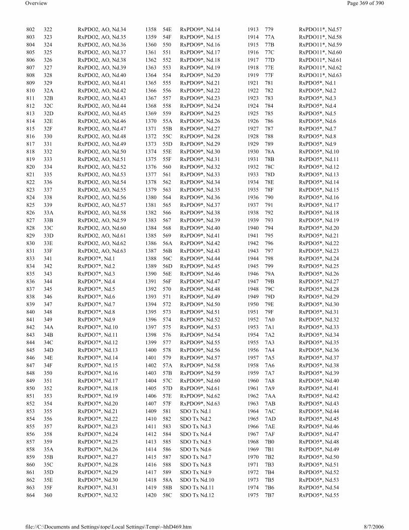
802 322 RxPDO2, AO, Nd.34 1358 54E RxPDO9*, Nd.14 1913 779 RxPDO11*, Nd.57803 323 RxPDO2, AO, Nd.35 1359 54F RxPDO9*, Nd.15 1914 77A RxPDO11*, Nd.58804 324 RxPDO2, AO, Nd.36 1360 550 RxPDO9*, Nd.16 1915 77B RxPDO11*, Nd.59805 325 RxPDO2, AO, Nd.37 1361 551 RxPDO9*, Nd.17 1916 77C RxPDO11*, Nd.60806 326 RxPDO2, AO, Nd.38 1362 552 RxPDO9*, Nd.18 1917 77D RxPDO11*, Nd.61807 327 RxPDO2, AO, Nd.39 1363 553 RxPDO9*, Nd.19 1918 77E RxPDO11*, Nd.62808 328 RxPDO2, AO, Nd.40 1364 554 RxPDO9*, Nd.20 1919 77F RxPDO11*, Nd.63809 329 RxPDO2, AO, Nd.41 1365 555 RxPDO9*, Nd.21 1921 781 RxPDO5*, Nd.1810 32A RxPDO2, AO, Nd.42 1366 556 RxPDO9*, Nd.22 1922 782 RxPDO5*, Nd.2811 32B RxPDO2, AO, Nd.43 1367 557 RxPDO9*, Nd.23 1923 783 RxPDO5*, Nd.3812 32C RxPDO2, AO, Nd.44 1368 558 RxPDO9*, Nd.24 1924 784 RxPDO5*, Nd.4813 32D RxPDO2, AO, Nd.45 1369 559 RxPDO9*, Nd.25 1925 785 RxPDO5*, Nd.5814 32E RxPDO2, AO, Nd.46 1370 55A RxPDO9*, Nd.26 1926 786 RxPDO5*, Nd.6815 32F RxPDO2, AO, Nd.47 1371 55B RxPDO9*, Nd.27 1927 787 RxPDO5*, Nd.7816 330 RxPDO2, AO, Nd.48 1372 55C RxPDO9*, Nd.28 1928 788 RxPDO5*, Nd.8817 331 RxPDO2, AO, Nd.49 1373 55D RxPDO9*, Nd.29 1929 789 RxPDO5*, Nd.9818 332 RxPDO2, AO, Nd.50 1374 55E RxPDO9*, Nd.30 1930 78A RxPDO5*, Nd.10819 333 RxPDO2, AO, Nd.51 1375 55F RxPDO9*, Nd.31 1931 78B RxPDO5*, Nd.11820 334 RxPDO2, AO, Nd.52 1376 560 RxPDO9*, Nd.32 1932 78C RxPDO5*, Nd.12821 335 RxPDO2, AO, Nd.53 1377 561 RxPDO9*, Nd.33 1933 78D RxPDO5*, Nd.13822 336 RxPDO2, AO, Nd.54 1378 562 RxPDO9*, Nd.34 1934 78E RxPDO5*, Nd.14823 337 RxPDO2, AO, Nd.55 1379 563 RxPDO9*, Nd.35 1935 78F RxPDO5*, Nd.15824 338 RxPDO2, AO, Nd.56 1380 564 RxPDO9*, Nd.36 1936 790 RxPDO5*, Nd.16825 339 RxPDO2, AO, Nd.57 1381 565 RxPDO9*, Nd.37 1937 791 RxPDO5*, Nd.17826 33A RxPDO2, AO, Nd.58 1382 566 RxPDO9*, Nd.38 1938 792 RxPDO5*, Nd.18827 33B RxPDO2, AO, Nd.59 1383 567 RxPDO9*, Nd.39 1939 793 RxPDO5*, Nd.19828 33C RxPDO2, AO, Nd.60 1384 568 RxPDO9*, Nd.40 1940 794 RxPDO5*, Nd.20829 33D RxPDO2, AO, Nd.61 1385 569 RxPDO9*, Nd.41 1941 795 RxPDO5*, Nd.21830 33E RxPDO2, AO, Nd.62 1386 56A RxPDO9*, Nd.42 1942 796 RxPDO5*, Nd.22831 33F RxPDO2, AO, Nd.63 1387 56B RxPDO9*, Nd.43 1943 797 RxPDO5*, Nd.23833 341 RxPDO7*, Nd.1 1388 56C RxPDO9*, Nd.44 1944 798 RxPDO5*, Nd.24834 342 RxPDO7*, Nd.2 1389 56D RxPDO9*, Nd.45 1945 799 RxPDO5*, Nd.25835 343 RxPDO7*, Nd.3 1390 56E RxPDO9*, Nd.46 1946 79A RxPDO5*, Nd.26836 344 RxPDO7*, Nd.4 1391 56F RxPDO9*, Nd.47 1947 79B RxPDO5*, Nd.27837 345 RxPDO7*, Nd.5 1392 570 RxPDO9*, Nd.48 1948 79C RxPDO5*, Nd.28838 346 RxPDO7*, Nd.6 1393 571 RxPDO9*, Nd.49 1949 79D RxPDO5*, Nd.29839 347 RxPDO7*, Nd.7 1394 572 RxPDO9*, Nd.50 1950 79E RxPDO5*, Nd.30840 348 RxPDO7*, Nd.8 1395 573 RxPDO9*, Nd.51 1951 79F RxPDO5*, Nd.31841 349 RxPDO7*, Nd.9 1396 574 RxPDO9*, Nd.52 1952 7A0 RxPDO5*, Nd.32842 34A RxPDO7*, Nd.10 1397 575 RxPDO9*, Nd.53 1953 7A1 RxPDO5*, Nd.33843 34B RxPDO7*, Nd.11 1398 576 RxPDO9*, Nd.54 1954 7A2 RxPDO5*, Nd.34844 34C RxPDO7*, Nd.12 1399 577 RxPDO9*, Nd.55 1955 7A3 RxPDO5*, Nd.35845 34D RxPDO7*, Nd.13 1400 578 RxPDO9*, Nd.56 1956 7A4 RxPDO5*, Nd.36846 34E RxPDO7*, Nd.14 1401 579 RxPDO9*, Nd.57 1957 7A5 RxPDO5*, Nd.37847 34F RxPDO7*, Nd.15 1402 57A RxPDO9*, Nd.58 1958 7A6 RxPDO5*, Nd.38848 350 RxPDO7*, Nd.16 1403 57B RxPDO9*, Nd.59 1959 7A7 RxPDO5*, Nd.39849 351 RxPDO7*, Nd.17 1404 57C RxPDO9*, Nd.60 1960 7A8 RxPDO5*, Nd.40850 352 RxPDO7*, Nd.18 1405 57D RxPDO9*, Nd.61 1961 7A9 RxPDO5*, Nd.41851 353 RxPDO7*, Nd.19 1406 57E RxPDO9*, Nd.62 1962 7AA RxPDO5*, Nd.42852 354 RxPDO7*, Nd.20 1407 57F RxPDO9*, Nd.63 1963 7AB RxPDO5*, Nd.43853 355 RxPDO7*, Nd.21 1409 581 SDO Tx Nd.1 1964 7AC RxPDO5*, Nd.44854 356 RxPDO7*, Nd.22 1410 582 SDO Tx Nd.2 1965 7AD RxPDO5*, Nd.45855 357 RxPDO7*, Nd.23 1411 583 SDO Tx Nd.3 1966 7AE RxPDO5*, Nd.46856 358 RxPDO7*, Nd.24 1412 584 SDO Tx Nd.4 1967 7AF RxPDO5*, Nd.47857 359 RxPDO7*, Nd.25 1413 585 SDO Tx Nd.5 1968 7B0 RxPDO5*, Nd.48858 35A RxPDO7*, Nd.26 1414 586 SDO Tx Nd.6 1969 7B1 RxPDO5*, Nd.49859 35B RxPDO7*, Nd.27 1415 587 SDO Tx Nd.7 1970 7B2 RxPDO5*, Nd.50860 35C RxPDO7*, Nd.28 1416 588 SDO Tx Nd.8 1971 7B3 RxPDO5*, Nd.51861 35D RxPDO7*, Nd.29 1417 589 SDO Tx Nd.9 1972 7B4 RxPDO5*, Nd.52862 35E RxPDO7*, Nd.30 1418 58A SDO Tx Nd.10 1973 7B5 RxPDO5*, Nd.53863 35F RxPDO7*, Nd.31 1419 58B SDO Tx Nd.11 1974 7B6 RxPDO5*, Nd.54864 360 RxPDO7*, Nd.32 1420 58C SDO Tx Nd.12 1975 7B7 RxPDO5*, Nd.55
Page 369 of 390Overview
8/7/2006file://C:\Documents and Settings\tope\Local Settings\Temp\~hhD469.htm

[This is preliminary documentation and subject to change.]
Introduction The TwinCAT System Manager automation interface enables the automatic creation and manipulation of TwinCAT configurations.
The automation of a TwinCAT configuration is available through two automation interfaces (derived from IDispatch) and can be used from high level languages (e.g. C++, VB or Java) and also from simple script languages (e.g. VBscript or Javascript). The ITcSysManager interface gives access to the main functions of the TwinCAT System Manager (open, save or activate configurations) and the ITcSmTreeItem interface (implemented by each tree item) gives access to all item specific functions and parameters. This interface gives direct access to a few general properties of the tree item - all specific properties and parameters can be accessed through a XML export and import (ITcSmTreeItem:ProduceXml and ITcSmTreeItem:ConsumeXml).
The documentation contains at first a description of these both interfaces and there methods and properties. All item specific parameters and functions are accessible through XML. These parameters are documented in the corresponding XML schema and an automatically generated schema documentation. The How to section of this documentation shows some examples how special configuration steps can be done and contains also script code fragments. This section contains an incomplete, unsorted and hopefully growing list of samples.
� ITcSysManager description � ITcSmTreeItem description � Schema documentation� How to section
Naming convention of tree items To reference to a specific tree item each tree item has a unique pathname. This pathname consists of the hierarchal order of parent names and the own name separated by tabs or circumflex accents '^'. To shorten the pathnames and to avoid language dependencies the top level tree items have special abbreviations as listed in ITcSysManager::LookupTreeItem.
XML schemas
Built on Tuesday, May 01, 2001
[This is preliminary documentation and subject to change.]
ITcSysManager Base interface of the TwinCAT System Manager automation interface. This interface is implemented by the System Manager and allows basic operations to configure the TwinCAT System. The ProgId of the implementing class is "TCatSysManager.TcSysManager".
This interface inherits from IDispatch and is accessible both from full featured languages (e.g. VB or C++) and script languages (e.g. VBscript or Javascript).
Methods in VTable Order
865 361 RxPDO7*, Nd.33 1421 58D SDO Tx Nd.13 1976 7B8 RxPDO5*, Nd.56866 362 RxPDO7*, Nd.34 1422 58E SDO Tx Nd.14 1977 7B9 RxPDO5*, Nd.57867 363 RxPDO7*, Nd.35 1423 58F SDO Tx Nd.15 1978 7BA RxPDO5*, Nd.58868 364 RxPDO7*, Nd.36 1424 590 SDO Tx Nd.16 1979 7BB RxPDO5*, Nd.59869 365 RxPDO7*, Nd.37 1425 591 SDO Tx Nd.17 1980 7BC RxPDO5*, Nd.60870 366 RxPDO7*, Nd.38 1426 592 SDO Tx Nd.18 1981 7BD RxPDO5*, Nd.61871 367 RxPDO7*, Nd.39 1427 593 SDO Tx Nd.19 1982 7BE RxPDO5*, Nd.62872 368 RxPDO7*, Nd.40 1428 594 SDO Tx Nd.20 1983 7BF RxPDO5*, Nd.63873 369 RxPDO7*, Nd.41 1429 595 SDO Tx Nd.21
TwinCAT System Manager: Automation
TwinCAT System Manager: Automation Reference
ITcSysManager Methods DescriptionNewConfiguration Generates a new configuration OpenConfiguration Loads a prior created configuration file (WSM file) SaveConfiguration Saves the configuration in a file with the given name or with the current name ActivateConfiguration Activates the configuration (same as "Save To Registry")
Page 370 of 390Overview
8/7/2006file://C:\Documents and Settings\tope\Local Settings\Temp\~hhD469.htm

Sample (vbscript): dim tsm set tsm = CreateObject("TCatSysManager.TcSysManager") call tsm.OpenConfiguration("c:\twincat\myConfig.wsm") call tsm.ActivateConfiguration call tsm.StartRestartTwinCAT
Sample (javascript): var tsm tsm = ActiveXObject("TCatSysManager.TcSysManager"); tsm.OpenConfiguration("c:\twincat\myConfig.wsm"); tsm.ActivateConfiguration(); tsm.StartRestartTwinCAT();
Comments The ITcSysmanager and the ITcSmTreeItem interface allows full access to a TwinCAT configuration. In the How to... section of this documentation there is a long (but incomplete) list of samples how to manipulate a TwinCAT configuration automatically.
Built on Thursday, March 08, 2001
[This is preliminary documentation and subject to change.]
ITcSmTreeItem Each tree item of a TwinCAT System Manager configuration implements a ITcSmTreeItem interface that enables various interactions with the tree item. This interface will be returned by a call to the ITCatSysManager::LookupTreeItem method.
Properties
LookupTreeItem Looks up to a configuration item (item in the tree) by name and returns a ITcSmTreeIteminterface
StartRestartTwinCAT Starts or Restarts the TwinCAT System IsTwinCATStarted Evaluates if the TwinCAT System is running LinkVariables Links two variables given by names UnlinkVariables Clears the link between two variables given by names or all links from one variable.
TwinCAT System Manager: Automation Reference
Property Type Access Allowed
Description
Name BSTR RW Name of tree itemComment BSTR RW Comment of tree item
Disabled BOOL RW
Disabled state of tree item can be one of the following enum:
� SMDS_NOT_DISABLED (item is enabled) � SMDS_DISABLED (item is disabled) � SMDS_PARENT_DISABLED (read only, set if one of its parent is disabled)
PathName BSTR R Tree name of tree item. The branches are separated by Tabs. The PathName can be used in method call to ITCatSysManager::LookupTreeItem
ItemType ENUM R Type of tree item defined by TREEITEMTYPES EnumItemSubType LONG RW Sub type of tree item, depending on the Item TypeItemSubTypeName BSTR RParent ITcSmTreeItem* R ITcSmTreeItem pointer of the parent
ChildCount LONG RNumber of childs. Childs counted by this property encloses only main childs of the tree item (e.g. boxes are main childs of a device but not the device process image). To access all childs use the _NewEnum property.
Child(LONG n) ITcSmTreeItem* R ITcSmTreeItem pointer of the n-th childVarCount((LONG x) LONG R Number of variables belonging to the tree item. x = 0 counted the input variables, x = 1 the outputsVar(LONG x, LONG n) ITcSmTreeItem* R ITcSmTreeItem pointer of the n-th variable. x = 0 uses the input variables, x = 1 the outputs
_NewEnum IUnknown* (IEnumVariant*)
R Returns a enum interface that enumerates all child tree items of the current tree item. This property is automatically used by the VB For-Each statement.
Page 371 of 390Overview
8/7/2006file://C:\Documents and Settings\tope\Local Settings\Temp\~hhD469.htm

Methods in Vtable Order
Item Types Following item types are currently defined:
typedef enum {
TREEITEMTYPE_UNKNOWN = 0, TREEITEMTYPE_TASK = 1, TREEITEMTYPE_DEVICE = 2, // I/O Device (e.g. "FC3101") TREEITEMTYPE_IMAGE = 3, // Process Image TREEITEMTYPE_MAPPING = 4, TREEITEMTYPE_BOX = 5, // I/O Box (e.g. "BK2000", child of I/O Devices) TREEITEMTYPE_TERM = 6, // I/O Terminal (child of terminal couplers (box) TREEITEMTYPE_VAR = 7, // Variable TREEITEMTYPE_VARGRP = 8, // Variable Group (e.g. "Inputs") TREEITEMTYPE_IECPRJ = 9, TREEITEMTYPE_CNCPRJ = 10, TREEITEMTYPE_GSDMOD = 11, // Module of a Profibus GSD device TREEITEMTYPE_CDL = 12, TREEITEMTYPE_IECLZS = 13, TREEITEMTYPE_LZSGRP = 14, TREEITEMTYPE_IODEF = 15, TREEITEMTYPE_ADDTASKS = 16, TREEITEMTYPE_DEVICEGRP = 17, TREEITEMTYPE_MAPGRP = 18, TREEITEMTYPE_NCDEF = 19, TREEITEMTYPE_NCAXISES = 20, TREEITEMTYPE_NCCHANNEL = 21, // NC Channel TREEITEMTYPE_NCAXIS = 22, // NC Axis TREEITEMTYPE_NCENCODER = 23, TREEITEMTYPE_NCDRIVE = 24, TREEITEMTYPE_NCCONTROLLER = 25, TREEITEMTYPE_NCGROUP = 26, TREEITEMTYPE_NCINTERPRETER = 27, TREEITEMTYPE_CANPDO = 30, TREEITEMTYPE_RTIMESET = 31, TREEITEMTYPE_BCPLC_VARS = 32, TREEITEMTYPE_FILENAME = 33, TREEITEMTYPE_DNETCONNECT = 34, TREEITEMTYPE_CAMDEF = 200, TREEITEMTYPE_CAMGROUP = 201, TREEITEMTYPE_CAM = 202, TREEITEMTYPE_CAMENCODER = 203, TREEITEMTYPE_CAMTOOLGRP = 204, TREEITEMTYPE_CAMTOOL = 205, TREEITEMTYPE_LINEDEF = 300, TREEITEMTYPE_ISGDEF = 400, TREEITEMTYPE_ISGCHANNEL = 401, TREEITEMTYPE_ISGAGROUP = 402, TREEITEMTYPE_ISGAXIS = 403, TREEITEMTYPE_MAX } TREEITEMTYPES;
Item Sub Types Item sub types depends on the item main type listed above:
TREEITEMTYPE_DEVICE
typedef enum {
ITcSmTreeItem Methods DescriptionCreateChild Creates a child item. DeleteChild Deletes a child item. ImportChild Imports a child item from the clipboard or a previously exported file. ExportChild Exports a child item to the clipboard or a file. ProduceXml Returns a BSTR containing the XML representation of the item specific data and parameter.
ConsumeXmlConsumes a BSTR containing the XML representation with item specific data and updates found parameters. This method is used to change the item parameter not directly accessible by the ITcSmTreeItem interface.
Page 372 of 390Overview
8/7/2006file://C:\Documents and Settings\tope\Local Settings\Temp\~hhD469.htm

IODEVICETYPE_UNKNOWN = 0, IODEVICETYPE_C1220 = 1, IODEVICETYPE_C1200 = 2, IODEVICETYPE_SPC3 = 3, // ProfiBus Slave (Siemens Card) IODEVICETYPE_CIF30DPM = 4, // ISA ProfiBus-Master 2 kByte (Hilscher Card) IODEVICETYPE_CIF40IBSM = 5, // ISA Interbus-S-Master 2 kByte (Hilscher-Card) IODEVICETYPE_BKHFPC = 6, // Beckhoff PC C2001 IODEVICETYPE_CP5412A2 = 7, // ProfiBus-Master (Siemens-Card) IODEVICETYPE_SERCANSISA = 8, // Sercos Master (Indramat) IODEVICETYPE_LPTPORT = 9, // Lpt Port IODEVICETYPE_DPRAM = 10, // Generic DPRAM IODEVICETYPE_COMPORT = 11, // COM Port IODEVICETYPE_CIF30CAN = 12, // ISA CANopen-Master (Hilscher-Card) IODEVICETYPE_CIF30PB = 13, // ISA ProfiBus-Master 8 kByte (Hilscher-Card) IODEVICETYPE_BKHFCP2030 = 14, // Beckhoff CP2030 (Pannel-Link) IODEVICETYPE_IBSSCIT = 15, // Interbus-S-Master (Phoenix-Card) IODEVICETYPE_CIF30IBM = 16, // ISA Interbus-S-Master (Hilscher-Card) IODEVICETYPE_CIF30DNM = 17, // ISA DeviceNet-Master (Hilscher-Card) IODEVICETYPE_FCXXXX = 18, // Beckhoff-FeldbusCard IODEVICETYPE_CIF50PB = 19, // PCI ProfiBus-Master 8 kByte (Hilscher-Card) IODEVICETYPE_CIF50IBM = 20, // PCI Interbus-S-Master (Hilscher-Card) IODEVICETYPE_CIF50DNM = 21, // PCI DeviceNet-Master (Hilscher-Card) IODEVICETYPE_CIF50CAN = 22, // PCI CANopen-Master (Hilscher-Card) IODEVICETYPE_CIF60PB = 23, // PCMCIA ProfiBus-Master (Hilscher-Card) IODEVICETYPE_CIF60DNM = 24, // PCMCIA DeviceNet-Master (Hilscher-Card) IODEVICETYPE_CIF60CAN = 25, // PCMCIA CANopen-Master (Hilscher-Card) IODEVICETYPE_CIF104DP = 26, // PC104 ProfiBus-Master 2 kByte (Hilscher-Card) IODEVICETYPE_C104PB = 27, // PC104 ProfiBus-Master 8 kByte (Hilscher-Card) IODEVICETYPE_C104IBM = 28, // PC104 Interbus-S-Master 2 kByte (Hilscher-Card) IODEVICETYPE_C104CAN = 29, // PC104 CANopen-Master (Hilscher-Card) IODEVICETYPE_C104DNM = 30, // PC104 DeviceNet-Master (Hilscher-Card) IODEVICETYPE_BKHFCP9030 = 31, // Beckhoff CP9030 (Pannel-Link with UPS, ISA) IODEVICETYPE_SMB = 32, // Motherboard System Management Bus IODEVICETYPE_PBMON = 33, // Beckhoff-PROFIBUS-Monitor IODEVICETYPE_CP5613 = 34, // PCI ProfiBus-Master (Siemens-Card) IODEVICETYPE_CIF60IBM = 35, // PCMCIA Interbus-S-Master (Hilscher-Card) IODEVICETYPE_FC200X = 36, // Beckhoff-Lightbus-I/II-PCI-Card IODEVICETYPE_FC3100 = 38, // Beckhoff-Profibus-PCI-Card IODEVICETYPE_FC5100 = 39, // Beckhoff-CanOpen-PCI-Card IODEVICETYPE_FC5200 = 41, // Beckhoff-DeviceNet-PCI-Card IODEVICETYPE_BKHFNCBP = 43, // Beckhoff NC Rückwand IODEVICETYPE_SERCANSPCI = 44, // Sercos Master (SICAN/IAM PCI) IODEVICETYPE_ETHERNET = 45, // Virtuelles Ethernet Device IODEVICETYPE_SERCONPCI = 46, // Sercon 410B or 816 Chip Master or Slave (PCI) IODEVICETYPE_IBSSCRIRTLK = 47, // Interbus-S-Master with Slave-Part LWL Basis (Phoenix-Card) IODEVICETYPE_FC7500 = 48, // Beckhoff-SERCOS-PCI-Card IODEVICETYPE_CIF30IBS = 49, // ISA Interbus-S-Slave (Hilscher-Card) IODEVICETYPE_CIF50IBS = 50, // PCI Interbus-S-Slave (Hilscher-Card) IODEVICETYPE_C104IBS = 51, // PC104 Interbus-S-Slave (Hilscher-Card) IODEVICETYPE_BKHFCP9040 = 52, // Beckhoff CP9040 (CP-PC) IODEVICETYPE_BKHFAH2000 = 53, // Beckhoff AH2000 (Hydraulik Backplane) IODEVICETYPE_BKHFCP9035 = 54, // Beckhoff CP9035 (Pannel-Link with UPS, PCI) IODEVICETYPE_MAX } IODEVICETYPES;
TREEITEMTYPE_BOX
typedef enum {
BOXTYPE_UNKNOWN = 0, BOXTYPE_BK2000 = 1, BOXTYPE_M1400 = 2, BOXTYPE_M2400 = 3, BOXTYPE_M3120_1 = 4, BOXTYPE_M3120_2 = 5, BOXTYPE_M3120_3 = 6, BOXTYPE_M3120_4 = 7, BOXTYPE_M3000 = 8, BOXTYPE_C1120 = 9, BOXTYPE_BK2010 = 10, BOXTYPE_AX2000 = 11, BOXTYPE_M2510 = 12, BOXTYPE_BK2020 = 20, BOXTYPE_BC2000 = 21, BOXTYPE_FOX20 = 31,
BOXTYPE_FOX50 = 32,
Page 373 of 390Overview
8/7/2006file://C:\Documents and Settings\tope\Local Settings\Temp\~hhD469.htm

BOXTYPE_FOXRK001 = 33, BOXTYPE_FOXRK002 = 34, BOXTYPE_CP1001 = 35, BOXTYPE_IPXB2 = 40, BOXTYPE_ILXB2 = 41, BOXTYPE_ILXC2 = 42,
BOXTYPE_BK3000 = 1001, BOXTYPE_BK3100 = 1002, BOXTYPE_PBDP_GSD = 1003, BOXTYPE_BK3010 = 1004, BOXTYPE_BK3110 = 1005, BOXTYPE_BK3500 = 1006, BOXTYPE_LC3100 = 1007, BOXTYPE_PBDP_DRIVE = 1008, BOXTYPE_BK3020 = 1009, BOXTYPE_BK3120 = 1010, BOXTYPE_BC3100 = 1011, BOXTYPE_PBDP_DRIVE2 = 1012, BOXTYPE_PBDP_DRIVE3 = 1013, BOXTYPE_PBDP_DRIVE4 = 1014, BOXTYPE_PBDP_DRIVE5 = 1015, BOXTYPE_PBDP_DRIVE6 = 1016, BOXTYPE_PBDP_DRIVE7 = 1017, BOXTYPE_PBDP_DRIVE8 = 1018, BOXTYPE_BK3XXX = 1021, BOXTYPE_BC3XXX = 1022, BOXTYPE_IPXB3 = 1030, BOXTYPE_ILXB3 = 1031, BOXTYPE_ILXC3 = 1032, BOXTYPE_TCPBDPSLAVE = 1100, BOXTYPE_TCFDLAGAG = 1101, BOXTYPE_TCMPI = 1102, BOXTYPE_TCPBMCSLAVE = 1103, BOXTYPE_TCPBMCSLAVE2 = 1104, BOXTYPE_TCPBMCSLAVE3 = 1105, BOXTYPE_TCPBMCSLAVE4 = 1106, BOXTYPE_TCPBMCSLAVE5 = 1107, BOXTYPE_TCPBMCSLAVE6 = 1108, BOXTYPE_TCPBMCSLAVE7 = 1109, BOXTYPE_TCPBMCSLAVE8 = 1110, BOXTYPE_TCPBMONSLAVE = 1111,
BOXTYPE_BK4000 = 2001, BOXTYPE_IBS_GENERIC = 2002, BOXTYPE_IBS_BK = 2003, BOXTYPE_BK4010 = 2004, BOXTYPE_BK4500 = 2005, BOXTYPE_BK4510 = 2006, BOXTYPE_IBS_SLAVEBOX = 2007, BOXTYPE_BC4000 = 2008, BOXTYPE_BK4020 = 2009, BOXTYPE_IPXB4 = 2030, BOXTYPE_ILXB4 = 2031, BOXTYPE_ILXC4 = 2032,
BOXTYPE_CP2020 = 2020,
BOXTYPE_SERCOSAXIS = 3001, BOXTYPE_BK7500 = 3011, BOXTYPE_BK7510 = 3012, BOXTYPE_BK7520 = 3013, BOXTYPE_SERCOSMASTERBOX = 3021, BOXTYPE_SERCOSSLAVEBOX = 3031,
BOXTYPE_BK8100 = 4001, BOXTYPE_BK8110 = 4002, BOXTYPE_BK8000 = 4003, BOXTYPE_BK8010 = 4004, BOXTYPE_CP9040 = 4005, BOXTYPE_BC8000 = 4011, BOXTYPE_BC8100 = 4012,
BOXTYPE_BK5100 = 5001, BOXTYPE_BK5110 = 5002,
BOXTYPE_CANNODE = 5003,
Page 374 of 390Overview
8/7/2006file://C:\Documents and Settings\tope\Local Settings\Temp\~hhD469.htm

BOXTYPE_BK5120 = 5004, BOXTYPE_LC5100 = 5005, BOXTYPE_IPXB51 = 5030, BOXTYPE_ILXB51 = 5031, BOXTYPE_ILXC51 = 5032,
BOXTYPE_BK5200 = 5201, BOXTYPE_BK5210 = 5202, BOXTYPE_DEVICENET = 5203, BOXTYPE_BK5220 = 5204, BOXTYPE_LC5200 = 5205, BOXTYPE_BK52XX = 5211, BOXTYPE_BC52XX = 5212, BOXTYPE_IPXB52 = 5230, BOXTYPE_ILXB52 = 5231, BOXTYPE_ILXC52 = 5232, BOXTYPE_TCDNSLAVE = 5250,
BOXTYPE_BK9000 = 9001, BOXTYPE_BC9000 = 9011, BOXTYPE_IPXB9 = 9030, BOXTYPE_ILXB9 = 9031, BOXTYPE_ILXC9 = 9032, BOXTYPE_REMOTETASK = 9041,
BOXTYPE_MAX } IOBOXTYPES;
Comments Built on Thursday, March 08, 2001
[This is preliminary documentation and subject to change.]
ITcSmTreeItem: Schema Documentation Under preparation....
[This is preliminary documentation and subject to change.]
How To... How to activate a previously created configurationHow to link variablesHow to unlink variablesHow to disable/enable a tree item (e.g. an I/O device)How to change the path to a plc project and/or rescan the projectHow to change the fieldbus address (station no.) of a profibus boxHow to export/import the information of a child of a tree itemHow to enumerate through the child's of a tree item
Explains the difference between the child's and all sub items of a tree item How to add child items (devices, boxes, terminals, variables etc.)How to update the address information of I/O devicesHow to create/change a linkage of a nc axis, encoder or drive to an I/O device, box or terminalHow to exchange a fieldbus device and move all childs to the new one
Back
Built on Tuesday, May 01, 2001
TwinCAT System Manager: Automation Reference
TwinCAT System Manager: Automation - How To...
TwinCAT System Manager: Automation - Samples.
Page 375 of 390Overview
8/7/2006file://C:\Documents and Settings\tope\Local Settings\Temp\~hhD469.htm

Overview
See Also How to... section, ITcSysManager, LookupTreeItem, ITcSmTreeItem, ExportChild, ImportChild
Built on Wednesday, November 02, 2005
TwinCAT Ethernet Driver - Installation The Intel 8255x based network interface card (NIC) should be plugged in and - automatically - detected and installed from Windows XP / 2000. After that, the driver of the device has to be changed. Open the 'Network Connections' (via Control Panel or 'Properties' of 'My Network Places') and open the 'Properties' of the LAN connection. If more than one NIC is installed, choose the one the Real-Time Ethernet shall be connected to.
The following screenshots are showing the necessary steps for the driver setup under Windows XP Professional.
The 'Properties' page appears. Please push the 'Configure...' button.
Description Visual Studio .NET 2003 SolutionsSample 1: Adding of Additional Tasks and Variables; TwinCAT Start / Stop C++: SysManSamples.exe (Self extracting)Sample 2: OpenConfiguration and CloseConfiguration, Scan Devices, Scan Boxes, Scan Terminals, Adding EtherCAT Devices, Import/Export C# : SysManSamples.exe (Self extracting
TwinCAT System Manager: Reference
Page 376 of 390Overview
8/7/2006file://C:\Documents and Settings\tope\Local Settings\Temp\~hhD469.htm

Select the 'Driver' Page and press the 'Update Driver...' button.
The 'Hardware Update Wizard' appears. Please select 'Install from a list or specific location (Advanced)' radio button and push 'Next'.
Page 377 of 390Overview
8/7/2006file://C:\Documents and Settings\tope\Local Settings\Temp\~hhD469.htm
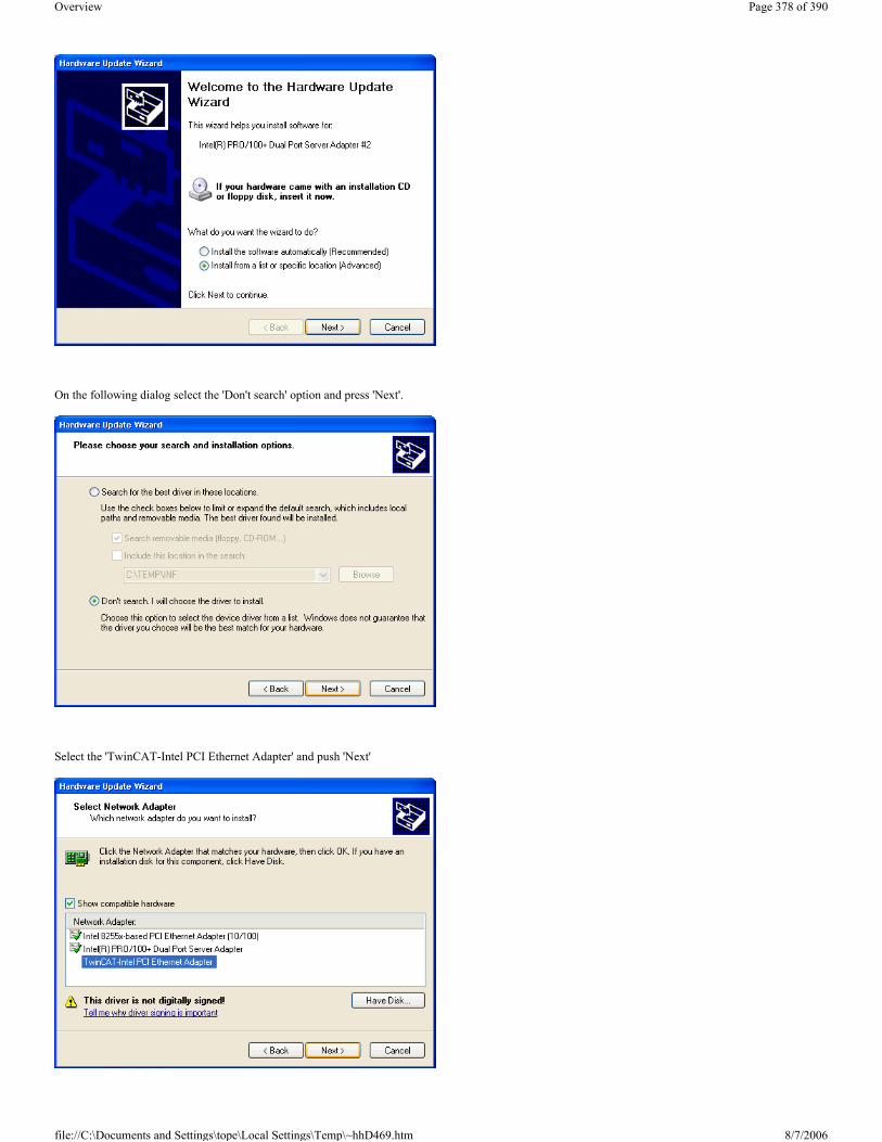
On the following dialog select the 'Don't search' option and press 'Next'.
Select the 'TwinCAT-Intel PCI Ethernet Adapter' and push 'Next'
Page 378 of 390Overview
8/7/2006file://C:\Documents and Settings\tope\Local Settings\Temp\~hhD469.htm

A warning will appear because the TwinCAT driver is not digitally signed by Microsoft - just trust Beckhoff...
The installation of the driver is now finished, but the TwinCAT protocol driver has to be installed still.
Please re-open the 'Properties' of the LAN connection - the new adapter driver should appear.
Page 379 of 390Overview
8/7/2006file://C:\Documents and Settings\tope\Local Settings\Temp\~hhD469.htm

Push the 'Install...' button and select the 'Protocol' choice. Press 'Add...' after this selection.
Select the 'TwinCAT Ethernet Protocol' from manufacturer 'Beckhoff'. If the protocol does not appear push the "Have Disk..." button and select the \Windows\Inf (Windows XP) or \WinNt\Inf (Windows 2000) directory. If the directory is not visible check the "Show hidden files or folder" radio button in the Explorer Tools/Folder Options/View dialog. After selecting the folder (doesn't matter which file is selected) the Beckhoff TwinCAT Ethernet Protocol should appear.
The new protocol should appear. The quality of service (QoS) packet scheduler filter driver can be disabled, because it has no function in reference to the
Page 380 of 390Overview
8/7/2006file://C:\Documents and Settings\tope\Local Settings\Temp\~hhD469.htm

TwinCAT driver.
Now the required steps are made. Only the 'TwinCAT Ethernet Protocol' did not start automatically for the first time. You have the choice to reboot the system or to start the protocol manually (only the very first time). To start the protocol manually, please open the command window (e.g. via the 'Run...' button on the start menu and enter 'cmd'). Enter in the command window the string 'net start TcEther' and press enter.
After that, the TwinCAT System Manager should find this new adapter underneath "I/O Devices".
Introduction of TwinCAT Real-Time Ethernet Ethernet communication in real-time
Ethernet takes the next step as a “Fieldbus” in Beckhoff’s TwinCAT control system. In addition to tough real-time requirements, it permits the use of standard components “on the same wire”. The BK9000 Ethernet Bus Coupler and the AX2000-B900 servo amplifier are the first Fieldbus components to benefit from the real-time capability. New network variables accelerate the real-time data exchange between controllers, making it as easy to implement as connecting another digital input.
Beckhoff’s range of Ethernet products has been in use for years, and is becoming increasingly popular. The advantages of using the office Ethernet standard communication method in industrial settings are clear: - Uses standard hardware components (e.g. a standard of-the-shelf Switch)
TwinCAT System Manager: Reference
Page 381 of 390Overview
8/7/2006file://C:\Documents and Settings\tope\Local Settings\Temp\~hhD469.htm

- Standard protocols can be employed - Data transmission rates are very high compared to other networks - Linking the network to the rest of the world over the Internet is straightforward - Remote maintenance and diagnosis
Communication over Ethernet has now become accepted in industrial automation and many groups and committees are concerning themselves with this topic. The absence of effective real-time capability, however, is a problem, which has limited Ethernet’s use in the classical fieldbus area. Some techniques do allow a certain degree of real-time capability, but are based on proprietary systems, and do not allow standard components and protocols to be used at the same time. - "Real-time capability" is a somewhat flexible term when used in control theory. - "Real-time" depends heavily on the requirements of the particular application and the control loops in which the automation components are used. However, from the point of view of automation engineering, and against the background that fieldbus specialist Beckhoff have to offer, a rough division can be drawn: - The toughest requirements involve cycle times of around 50 µs and permissible jitter (deviations from the desired cycle time) of around 10 µs. Requirements tighter than this are currently still handled with the aid of special hardware rather than directly over fieldbusses. Typical cycle time requirements with position-controlled drives are in the range of milliseconds (1-4 ms), in which case jitter times should be less than 20 µs. Pure PLC applications often require cycle times no shorter than 10 ms; correspondingly, jitter times may here be significantly longer, and lie in the millisecond range. Data communication between the controller and the supervisory system can often satisfactorily be handled with cycle times in the range of seconds. In fact it may not be configured cyclically, but may be event driven.
Remote servicing and diagnosis should also be mentioned. Cycle and jitter times here are less relevant than reaction times and the general possibility of being able to communicate across the boundaries of networks. TwinCAT automation software now offered with Real-time Ethernet means that all the communication requirements that have just been mentioned can be satisfied using one and the same technology, both from the point of view of the devices used and of the protocols employed.
Principle of operation
The TwinCAT network card driver is linked into the system in such a way that it appears as a network driver, compatible with the operating system, and additionally as a TwinCAT fieldbus card. An internal prioritization system and buffer is provided at the transmitter end which always finds a free transmission channel for Ethernet frames from the real-time system that may be queuing. The operating system’s Ethernet frames are only later transmitted in the “gaps” if sufficient time is available.At the receiving end, all the Ethernet frames received are examined by the TwinCAT I/O system, and those with real-time relevance are filtered out. All other frames are passed on to the operating system after examination, outside the context of the real-time system.
Using commercially available switches, all of which support full duplex operation at 100 Mbaud, the transmitted frames are passed on to the receiver with a constant delay. A switch ensures that collisions are avoided and only delays occur. In a cyclic control system it is therefore only necessary to ensure that all the relevant input information has arrived before the next cycle starts. When, or in what sequence, they have arrived is not significant. If the number of participating devices or the frame rate is restricted in accordance with the required cycle time, the preconditions for Ethernet communication with real-time capability are satisfied.
The above picture shows the principle of how the original Windows operating system protocol stack (TCP/IP and UDP/IP) is used besides TwinCAT Real-Time Ethernet. We call this principle "Y-driver" architecture.
Operating modes/protocols
Page 382 of 390Overview
8/7/2006file://C:\Documents and Settings\tope\Local Settings\Temp\~hhD469.htm

In contrast to the widely used TCP/IP and UDP/IP protocols, which are responsible for the provision of individual Ethernet frames around the world, real-time communication does not leave the local subnet. The overhead involved in TCP/IP, and even that of UDP/IP, can be omitted, and the devices can be addressed directly by means of the hardware addresses (MAC-ID) of the network cards. The structure of Ethernet frames ensures that it is always possible to co-exist with other protocols; even the “real-time frames” can, if necessary, be transmitted with TCP or UDP, if they have to leave their own subnet. A number of different operating modes have been defined for use in control engineering. They serve different communication tasks, and can, of course, be employed simultaneously.
1.) Master-slave process data communication
Cyclic or event-driven transmission of I/O data – the typical use of modern fieldbusses
2.) Publisher-subscriber process data communication
Process data according to the publisher-subscriber model (also referred to as network variables) is used for regular communication between controllers when a fixed master-slave relationship would not be appropriate. The Publisher sends out its information without concerning itself with where it is going. The communication is only monitored in the Subscriber. Mutual publisher-subscriber relationships permit bi-directional and multi-directional communication. The publisher can be configured to send the data by broadcast, multicast or unicast. Multicasts reduce the loads at the network devices’ receive queues, because the messages are evaluated as soon as they reach the Ethernet controller. Only if unicasts are used the switch (without extensive configuration) can open parallel communication paths and increase the useful bandwidth.
3.) Data communication as required
This is a type of communication made possible in the TwinCAT system through ADS communication, and which sends communication strings from one device to another “as required”. Services are executed and parameters exchanged in this way.
The chosen protocol structure means that other operating modes or communication profiles can easily be integrated in the future, and can co-exist with the existing modes without difficulty.
Compatible components
The first components from the Beckhoff product range to have been extended for real-time Ethernet application are the BK9000 Ethernet Bus Coupler and the AX2000-B900 drive. These two components open up almost the entire range of industrial signals and applications. All TwinCAT controllers (from Version 2.9 upwards) are compatible, and can participate both as “fieldbus masters” and in communication using network variables. TwinCAT Real-Time Ethernet supports all controllers (network adapters) of the Intel 8255x family. This is one of the most widespread Ethernet controllers, a component in the latest Intel chip set, which already include a compatible network connection. Support for further Ethernet controllers in the future may be considered – in the light of the wide popularity of the Intel family and its compatibility even with Gigabit Ethernet (Intel 8254x family) – but not absolutely essential. The new Embedded-PC CX1000 small controller is, of course, always fitted with an appropriate Ethernet controller.
Performance
Judging the performance of a fieldbus system exclusively on the basis of the baudrate is, without doubt, too simple, ignoring as it does other significant communication parameters such as the efficiency of the protocols, reaction time, jitter, minimum telegram length, pause times and so forth. All the same, 100 Mbaud permit significantly faster data transfer than is usual at present in fieldbus environments. In addition to this, the protocols used provide a significantly improved efficiency in contrast with TCP or UDP communication, in particular when data telegrams are short. One factor which is often ignored when considering the capacity of a fieldbus system is the transfer of data between the controller CPU to the communication chip or processor; that is to say, between the host system memory and the subsystem memory. In PC based controllers, the data is usually copied over the ISA or PCI bus into the DPRAM of a fieldbus master card, and vice-versa. Whereas PC processors have reached speeds of around 3 GHz, even the supposedly fast PCI bus has become a bottleneck, so that 20-30 % of the CPU performance is lost for PCI transfers. Modern network controllers operate in what is known as the “bus master DMA mode”, accessing the host system’s memory directly. This occurs in parallel with other CPU tasks, and therefore significantly reduces the CPU load.
Applications/Linking to TwinCAT
The high data transfer capacity, the fundamental real-time capability and the protocols that are employed cover all the communication demands made by a fast machine controller. When all these features are considered we are soon led to the conclusion that classical fieldbusses are no longer needed. First of all, however, Ethernet technology must still be proven at the field level, and must meet all requirements such as those for simplicity of installation and configuration, mutual compatibility, EMC immunity and, not least, efficiency and device costs relevant to the industrial environment. Standard fieldbusses are widely accepted, and there are many devices offered by many vendors including Beckhoff. Therefore, they will continue to have great significance to the market. Here once again, TwinCAT’s flexible I/O system offers a way forward: It permits multiple fieldbusses to be operated in parallel, including, of course, the parallel operation of classical fieldbusses with real-time Ethernet – and all of this is entirely transparent to the application.
Application Example 1:
Page 383 of 390Overview
8/7/2006file://C:\Documents and Settings\tope\Local Settings\Temp\~hhD469.htm

Relatively simple applications can manage with a single Ethernet connection, both for the real-time communication to the I/O level and for the higher-level communication for the purposes of administration and remote diagnosis. The prioritization that is used ensures that the real-time communication takes place without difficulty.
Application Example 2:
Larger applications make use of a second Ethernet connection, and divide the real-time communication and the higher level communication between two networks. The routing that is required in order, for instance, to remotely diagnose a drive that is connected to a real-time network is performed automatically by the operating system’s IP stack, and does not require any proprietary conversion to a different protocol.
Application Example 3:
Very large applications, for which the computing power even of a 3 GHz system is insufficient, can distribute the control tasks between a number of PC controllers, and can exchange even large amounts of data quasi-synchronously with the cycles (even at sub-millisecond speeds), using the real-time capable network variables.
Introduction Network variable are variables which can be exchanged cyclic between PC/CX1000. Any elementary or complex datatypes can be exchanged. A Publisher/Subscriber model is used. For deterministic communication the Realtime-Ethernet Driver for TwinCAT has to be installed.
Publisher/Subscriber Model
With the Publisher/Subscriber model one publisher makes variable available in the network. Any PC/CX1000 can 'subscribe' to one of these variables. The publisher can allow access for one PC/CS1000, a set of PC/CX1000 or all PC/CX1000 in the network. With a Broadcast the variable can be accessed from all PC/CX1000, a Multicast allows access to a set of selected PC/CX1000 and a Unicast allows access only to one PC/CX1000. A Subscriber can also be a Publisher. With this a bidirectional connection is possible.
TwinCAT System Manager: Netzwork Variables
Page 384 of 390Overview
8/7/2006file://C:\Documents and Settings\tope\Local Settings\Temp\~hhD469.htm

Unicast
The Publisher allows access of a network variable only for one selected PC.
Multicast
The Publisher allows access of a network variable to a set of selected PCs.
Broadcast
The Publisher allows access of a network variable to all PCs in the network.
Configuration of the Publisher Add a new Publisher Box beneath the RT-Ethernet device.
Insert a Publisher Box
Add a new Publisher Box beneath the RT-Ethernet device.
Insert a Network variable
Insert a Network Variable beneath the box. A name and a datatype for the new network variable is neccessary (i.e. nCounterPub and UINT32/UDINT).
TwinCAT System Manager: Network Variables
Page 385 of 390Overview
8/7/2006file://C:\Documents and Settings\tope\Local Settings\Temp\~hhD469.htm

New inputs and outputs will appear beneath the network variable.
FrameState shows the state of the send Ethernet frames.
Possible values are:
With FrameCtrl a Control Word can be written for Ethernet frame.
Possible values are:
Short description Value DescriptionNot sent (frame skipped) 0x0001
Error (frame oversized) 0x0001 The limit of a Ethernet frame is exceeded. The mapped variable must have a lower number of
bytes.
Short description Value Description
Page 386 of 390Overview
8/7/2006file://C:\Documents and Settings\tope\Local Settings\Temp\~hhD469.htm

VarState input shows the state of the network variable.
Possible values are:
With VarCtrl a control word can be written for each network variable.
Possible values are:
Mapping
A network variable on the publisher side can be mapped to an output variable of the right datatype of any device. The example shows a mapping of a network variable to an output variable of a PLC.
Configuration of the Subscriber Add a new Subscriber Box beneath the RT-Ethernet device.
Insert a Subscriber Box and connect to Publisher
Disable sending 0x0001 Sending frames is interrupted. When FrameCtrl is zero again sending of frames begins again.
Short description Value Description
Not sent (variable skipped) 0x0001
Short description Value Description
Disable publishing 0x0001 Sending network variable is interrupted. When VarCtrl is zero again sending of network variable begins again.
TwinCAT System Manager: Network Variables
Page 387 of 390Overview
8/7/2006file://C:\Documents and Settings\tope\Local Settings\Temp\~hhD469.htm

Add a new Subscriber Box beneath the RT-Ethernet device.
Insert a Network variable
Insert a Network Variable beneath the box.
The connection to the publisher network variable can be done automatically. Select the publisher computer and select a variable. Name and datatype information is given by the publisher.
Page 388 of 390Overview
8/7/2006file://C:\Documents and Settings\tope\Local Settings\Temp\~hhD469.htm

New inputs and outputs will appear beneath the network variable.
FrameState and FrameCtrl show the state/control of the received Ethernet frames. Both variables are reserved and not supported on the subscriber side.
VarState and VarCtrl show the state/control of the received network variable. Both variables are reserved and not supported on the subscriber side.
Quality of Network variables
The quality of a network variable is shown on the subscriber side. Two inputs can be used. The variable quality shows a counter in 100µs resolution. The counter is incremented when the update of the variable is not in time. The sample shows the online quality variable after disconnection of the network plug for a while (counter is incremented) and plug in again (counter is zero).
Page 389 of 390Overview
8/7/2006file://C:\Documents and Settings\tope\Local Settings\Temp\~hhD469.htm

The CycleIndex variable is incremented with each publisher cycle.
Page 390 of 390Overview
8/7/2006file://C:\Documents and Settings\tope\Local Settings\Temp\~hhD469.htm