Embed Size (px)
Citation preview
Meridian 1
Meridian 1 European Digital Telephones
Document Number: 553-3001-114Document Release: Standard 3.00Date: April 2000
Year Publish FCC TM
Copyright © 1997–2000 Nortel NetworksAll Rights Reserved
Printed in Canada
Information is subject to change without notice. Nortel Networks reserves the right to make changes in design or components as progress in engineering and manufacturing may warrant. This equipment has been tested and found to comply with the limits for a Class A digital device pursuant to Part 15 of the FCC rules, and the radio interference regulations of Industry Canada. These limits are designed to provide reasonable protection against harmful interference when the equipment is operated in a commercial environment. This equipment generates, uses and can radiate radio frequency energy, and if not installed and used in accordance with the instruction manual, may cause harmful interference to radio communications. Operation of this equipment in a residential area is likely to cause harmful interference in which case the user will be required to correct the interference at their own expense.
SL-1 and Meridian 1 are trademarks of Nortel Networks.
Meridian 1 European Digital Telephones

Page 3 of 46
4
Revision historyApril 2000
Standard 3.00. This is a global document and is up-issued for X11 Release 25.0x.
February 1997Standard, release 2.00 based on changes in product.
October 1996Standard, release 1.00 for Gate 2A.
Meridian 1 European Digital Telephones
Page 4 of 46 Revision History
553-3001-114 Standard 3.00 April 2000
Page 5 of 46
6
7
99
171821
21222222
22
2222
3535363637
Contents
Preface . . . . . . . . . . . . . . . . . . . . . . . . . . . . . . . . . . . 7Other documentation . . . . . . . . . . . . . . . . . . . . . . . . . . . . . . . . . . . . . .
Meridian digital telephones . . . . . . . . . . . . . . . . . . 9Functional description . . . . . . . . . . . . . . . . . . . . . . . . . . . . . . . . . . . . .
General features . . . . . . . . . . . . . . . . . . . . . . . . . . . . . . . . . . . . . . . . Meridian digital telephones used with a headset . . . . . . . . . . . . . . . Physical characteristics . . . . . . . . . . . . . . . . . . . . . . . . . . . . . . . . . . Software requirements . . . . . . . . . . . . . . . . . . . . . . . . . . . . . . . . . . .
Terminal Options . . . . . . . . . . . . . . . . . . . . . . . . . . . . . . . . . . . . . . . . . External Alerter interface . . . . . . . . . . . . . . . . . . . . . . . . . . . . . . . . Brandline insert . . . . . . . . . . . . . . . . . . . . . . . . . . . . . . . . . . . . . . . . Key Expansion Module . . . . . . . . . . . . . . . . . . . . . . . . . . . . . . . . . . Meridian Communications Adapter (MCA) . . . . . . . . . . . . . . . . . .
Installation . . . . . . . . . . . . . . . . . . . . . . . . . . . . . . . . . . . . . . . . . . . . . . Configuration and Installation . . . . . . . . . . . . . . . . . . . . . . . . . . . . .
Specifications . . . . . . . . . . . . . . . . . . . . . . . . . . . . . . . . . . . . . . . . . . . . Environmental and safety considerations . . . . . . . . . . . . . . . . . . . . Line engineering . . . . . . . . . . . . . . . . . . . . . . . . . . . . . . . . . . . . . . . Local alerting tones . . . . . . . . . . . . . . . . . . . . . . . . . . . . . . . . . . . . . Power requirements . . . . . . . . . . . . . . . . . . . . . . . . . . . . . . . . . . . . .
Glossary . . . . . . . . . . . . . . . . . . . . . . . . . . . . . . . . . . 43
Index . . . . . . . . . . . . . . . . . . . . . . . . . . . . . . . . . . . . . 45
Meridian 1 European Digital Telephones
Page 6 of 46 Contents
553-3001-114 Standard 3.00 April 2000
Page 7 of 46
8
ur
n
r
PrefaceThis document is a global document. Contact your system supplier or yoNortel Networks representative to verify that the hardware and software described is supported in your area.
This guide provides feature, add-on module, and specification informatiofor Meridian digital telephones.
Other documentationFor more information, refer to the following documentation:
• Digital Telephone Line Engineering (553-2201-180)
• Meridian Communications Unit and Meridian Communications Adapter: Description, Installation, Administration, Operation (553-2731-109)
• Spares Planning (553-3001-153)
• Equipment Identification (553-3001-154)
• Line Cards: Description (553-3001-105)
• Telephone and Attendant Console: Installation (553-3001-215)
• X11 Features and Services (553-3001-306)
• X11 Administration (553-3001-311)
• Asynchronous Data user guide
• Meridian Digital Telephones: M3902, M3903, M3904 Quick Reference Guide)
• Meridian Digital Telephones: M3901, M3902, M3903, M3904 UseGuide
Meridian 1 European Digital Telephones
Page 8 of 46 Preface
553-3001-114 Standard 3.00 April 2000
Page 9 of 46
42
ion
ted ey
ard
ire
hile
e and N is
of
Meridian digital telephonesThis chapter provides feature, add-on module, relocation, and specificatinformation for Meridian digital telephones.
Functional descriptionMeridian digital telephones are designed to provide cost-effective integravoice and data communication. These telephones communicate with theMeridian 1 using digital transmission over standard twisted-pair wiring. Thinterface with the Meridian 1 using the Integrated Services Digital Line C(ISDLC) or the eXtended Digital Line Card (XDLC).
Meridian digital telephones are connected to the system through a two-wloop carrying two independent 64 kbs PCM channels with associated signaling channels. One of the two PCM channels is dedicated to voice wthe other is dedicated to data traffic.
The telephone interfaces with the Digital Line Card (XDLC) or ISDLC in thPeripheral Equipment shelf of the system. The XDLC supports 16 voice 16 data ports. The ISDLC supports eight voice and eight data ports. A Tassigned to each port in the system software.
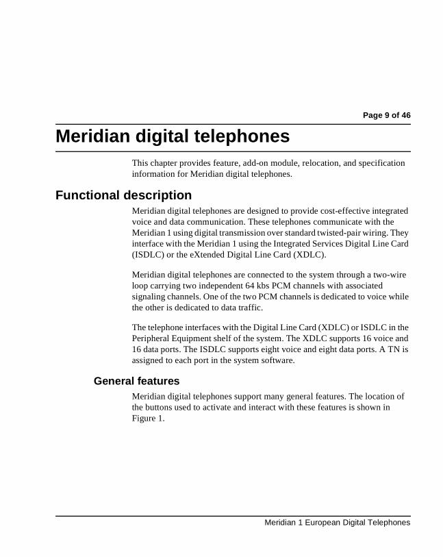
General featuresMeridian digital telephones support many general features. The locationthe buttons used to activate and interact with these features is shown inFigure 1.
Meridian 1 European Digital Telephones
Page 10 of 46 Meridian digital telephones
Figure 1The Location and Function of Buttons on the Meridian digital telephone
Program Key†LCD Indicators
Display Module†
Feature Keys
Release (Rls) KeyMessage WaitingIndicator
Hold Key
Speaker
Speaker/Mute LEDSpeaker Key
Mute Key
Edit Key*
Callers List Key*
Cursor Keys*
Directory Key*
Delete Key*
Dial Key*Main Extension Keyor Directory Number (DN) key
† M3310 and M3820 only
* M3820 only
553-3001-114 Standard 3.00 April 2000
Meridian digital telephones Page 11 of 46
s:
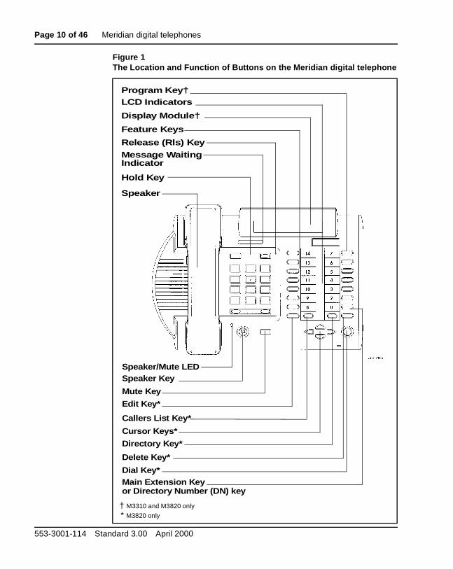
The three telephones that support the various feature levels are as followM3820
The M3820 Meridian digital telephone supports the following features:
• Handsfree, On-Hook Dialling and Group Listening
• Dedicated Release and Hold keys
• Message Waiting and Speaker/Mute Indicators
• Headset Socket
• 2 x 24 character display
• 20 Feature keys including:
— Store/program key
— 13 system programmable keys
— Handsfree/speaker key
— Mute key
Figure 2M3820 Meridian digital telephone
Meridian 1 European Digital Telephones
Page 12 of 46 Meridian digital telephones
— Directory key
— Caller’s List key
— Edit key
— Delete key
• Volume control for:
— Handset/Headset
— Ringing Tone
— Buzz Tone
— On-Hook dialling and Group Listening
— Handsfree
• Directory/Caller’s List with 9 dedicated keys namely:
— Directory, Callers, Edit, Delete, 4 cursor and Dial
• Support for the following terminal options:
— MCA data option to provide integrated voice and data
— External Alerter for high ambient noise environments
— Wall mount ability
— Add-on Key Expansion Modules (2 maximum)
• Brand line insert to provide for special company logos
553-3001-114 Standard 3.00 April 2000
Meridian digital telephones Page 13 of 46
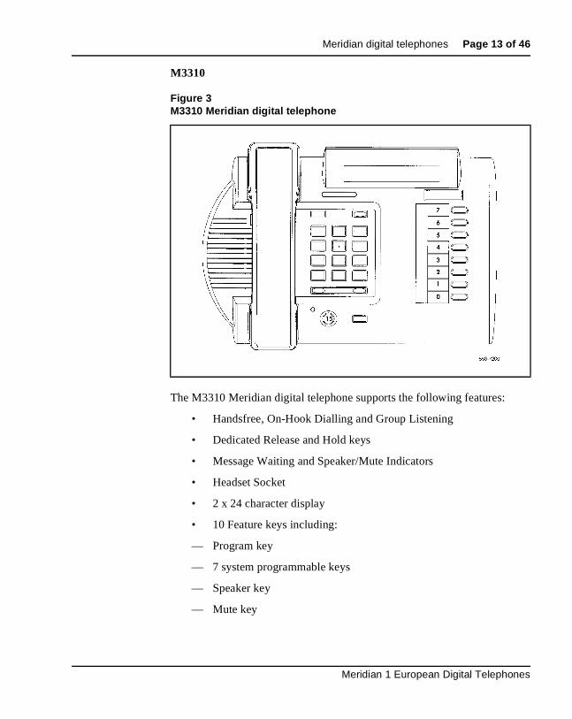
M3310
The M3310 Meridian digital telephone supports the following features:
• Handsfree, On-Hook Dialling and Group Listening
• Dedicated Release and Hold keys
• Message Waiting and Speaker/Mute Indicators
• Headset Socket
• 2 x 24 character display
• 10 Feature keys including:
— Program key
— 7 system programmable keys
— Speaker key
— Mute key
Figure 3M3310 Meridian digital telephone
Meridian 1 European Digital Telephones
Page 14 of 46 Meridian digital telephones
— Volume control for:
— Handset/Headset
— Ringing Tone
— Buzz Tone
— On-Hook dialling and Group Listening
— Handsfree
• Support for the following set options:
— MCA data option to provide integrated voice and data
— External Alerter for high ambient noise environments
— Wall mount ability
• Brand line insert to provide for special company logos
553-3001-114 Standard 3.00 April 2000
Meridian digital telephones Page 15 of 46
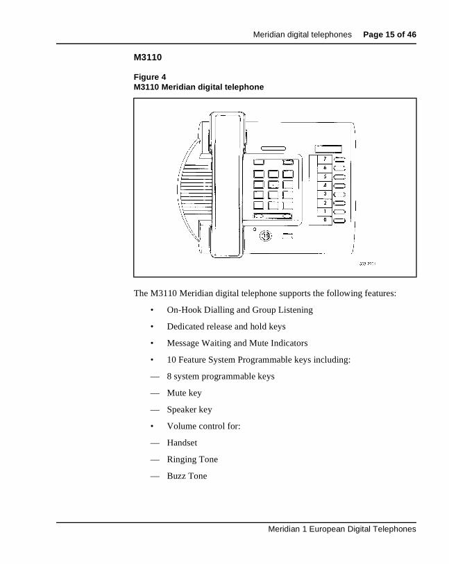
M3110
The M3110 Meridian digital telephone supports the following features:
• On-Hook Dialling and Group Listening
• Dedicated release and hold keys
• Message Waiting and Mute Indicators
• 10 Feature System Programmable keys including:
— 8 system programmable keys
— Mute key
— Speaker key
• Volume control for:
— Handset
— Ringing Tone
— Buzz Tone
Figure 4M3110 Meridian digital telephone
Meridian 1 European Digital Telephones
Page 16 of 46 Meridian digital telephones
— On-Hook dialling and Group Listening
• Support for the following terminal options:
— MCA data option to provide integrated voice and data
— External Alerter for high ambient noise environments
• Wall mount ability
• Brand line insert to provide for special company logos
553-3001-114 Standard 3.00 April 2000
Meridian digital telephones Page 17 of 46
nes t
the
e
s.
ms.
Meridian digital telephones used with a headsetYou can use an electret headset in the headset port of the digital telepho(M3310 and M3820 only). Alternatively, choose an amplified headset thadraws power from a battery or AC transformer; power is not provided by telephone. The amplifier must draw less than 400 micro amps from the telephone jack.
The headset should be designed to work with a telephone jack with thescharacteristics:
Transmit interface: +5 V through 10K DC bias resistance with maximumcurrent of 500 micro amps. The differential input impedance is 10K ohmConnects to pins 2 and 5 of the headset jack.
Receive interface: single ended output with output impedance of 180 ohConnects to pins 3 and 4 of the headset jack.
Meridian 1 European Digital Telephones
Page 18 of 46 Meridian digital telephones
ld. ing
Rls
et, ht
ou ee,
ble
Physical characteristicsFixed keys (same for all three models)
• Hold: By pressing the hold key, you can put an active call on hoReturn to the caller by pressing the extension key beside the flashLCD indicator.
• Release (Rls): You can terminate an active call by pressing the key or by hanging up the handset. The release key is especiallyuseful for disconnecting handsfree and headset calls.
• Volume control: The volume key controls the volume of the handsthe speaker and the ringer. Raise the volume by pressing the rigside of the bar. Lower it by pressing the left side.
• Mute: When engaged in a call, you can press the mute key. Theparty(ies) to whom you are speaking cannot hear you. This is especially useful when on a conference call and you are only listening. When you wish to return to the two-way conversation, ymust push the mute key again. The mute key applies to handsfrhandset and headset microphones.
• Speaker/Handsfree: The speaker key allows you to activate handsfree and group listening features. Handsfree is only availaon the M3310 and M3820 models and is enabled by the systemadministrator. If handsfree is not configured at the switch, the telephone can only be used to listen.
553-3001-114 Standard 3.00 April 2000
Meridian digital telephones Page 19 of 46
ey is
r, user arties
both
The table below indicates the mode the terminal is in when the speaker koperated under the various switch and set operations.
Note 1: CPM is Call Process Monitor which enables the user to heafor example, the dial tone in the speaker. Group listening enables the to speak through the handset/headset microphone and one or more pcan listen through the speaker, thus hearing both sides of the conversation. In Handsfree mode, the user (or group of users) usesthe handsfree microphone and speaker.
Table 1Speaker Key Function
MODELHandsfree not selected at the
switch
Handsfree selected at the switch -
Group listening off
Handsfree selected at the switch - Group
listening On
M3820 CPM and primary DN key-Speaker LED is not illuminated
HF and Primary DN key - speaker LED is on when in Handsfree mode
HF, Group listening and Primary DN key - speaker LED is on when in HF or Group Listening mode
M3310 CPM and Primary DN key-Speaker LED is not illuminated
HF and Primary DN key - Speaker LED is on when in HF mode
HF, Group Listening and Primary DN key - Speaker LED is on when in HF or group listening
M3110 CPM and Primary DN key- Speaker LED is not illuminated
N/A Group listening and Primary DN key - speaker LED is on when in Group listening mode.
Meridian 1 European Digital Telephones
Page 20 of 46 Meridian digital telephones
D ting. t a f
ter air
th ers 310
but .
Note 2: Group listening is switched on or off under the program keyoption *1. (M3820 and M3310 only)
Additional feature keysMessage Waiting lamp key. Each telephone has a red message waiting LEjust above the hold and Rls keys that lights to indicate a message is waiThis LED is the primary message waiting indicator and lets you know thamessage is waiting, regardless of whether the telephone has a messagewaiting key/lamp pair. You must have Message Waiting allowed Class oService. See LD 11, X11 Administration (553-3001-311) and X11 Maintenance (553-3001-511).
If you do assign a message waiting key/lamp pair, there will be two indications of a message waiting:
— the red Message Waiting LED lights
— the LCD associated with the Message Waiting key blinks
Autodial key. You can assign an Autodial Key that dials the message cen(or voice mail system) to avoid the double indication or have no key/lamp passigned to the message center.
Programmable Feature keysEach Meridian digital telephone has a number of programmable keys wiLCD indicators that can be assigned to any combination of directory numband features. The M3820 has 13 fully programmable feature keys; the M3has seven, and the M3110 has eight. The lower right-hand key (key 0) isreserved for the Primary DN.
LCD indicators support four key/LCD states:
Function LCD stateidle off
active on (steady)
ringing flash (60 Hz)
hold fast flash (120 Hz)
Note: An indicator fast flashes when you have pressed a feature keyhave not completed the procedure necessary to activate the feature
553-3001-114 Standard 3.00 April 2000
Meridian digital telephones Page 21 of 46
0.) (89)
es. one.
Software requirementsMeridian digital telephones are supported by X11 release 16 and later software. The package number for the Meridian digital telephones is (17The mnemonic is ARIE. The DSET package (88) and the TSET package are required.
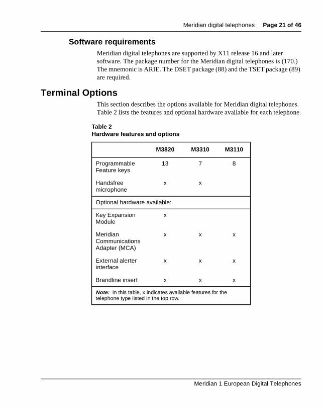
Terminal OptionsThis section describes the options available for Meridian digital telephonTable 2 lists the features and optional hardware available for each teleph
Table 2Hardware features and options
M3820 M3310 M3110
Programmable Feature keys
13 7 8
Handsfree microphone
x x
Optional hardware available:
Key Expansion Module
x
Meridian Communications Adapter (MCA)
x x x
External alerter interface
x x x
Brandline insert x x x
Note: In this table, x indicates available features for the telephone type listed in the top row.
Meridian 1 European Digital Telephones
Page 22 of 46 Meridian digital telephones
ing
ut rter
ht)
on
stom een
eys up to for
inal. uter
hose
External Alerter interfaceThe External Alerter Board provides an interface to standard remote ringdevices, such as a ringing unit, installed in a location separate from the telephone. The External Alerter interface is not the remote ringer itself, bprovides access to standard, off-the-shelf remote ringing devices. The AleBoard requires additional power. See “Power requirements” on page 37.
You can program the External Alerter interface to activate a ringer (or ligwhen the telephone rings or when the telephone is in use (off-hook).
For information on installing and setting up the External Alerter, see “Add-modules” in Telephone and Attendant Console: Installation (553-3001-215).
Brandline insertThe telephone contains a removable insert designed to accommodate culabeling. You can order blank Brandline Inserts and have a printer silk scryour company logo on them.
Key Expansion ModuleA 22-key unit module can be attached to any M3820 terminal. The extra kcan be assigned to any combination of lines and features. You can add two expansion modules to a terminal. You will need a separate footstandthe module(s), one for a single module, one for a double.
Meridian Communications Adapter (MCA)The MCA lets you connect your telephone to a personal computer or termYou can then use your telephone to exchange data between your compand other computers. The MCA can be used with all three models.
InstallationConfiguration and Installation
ConfigurationUse Overlay 11 (Meridian Digital Telephone Administration) to configurethe telephones. All prompts are defaulted (or set as required) except for tnoted in the tables following:
553-3001-114 Standard 3.00 April 2000
Meridian digital telephones Page 23 of 46
Table 3M3110 Configuration
Prompt Response Comments
REQ NEW
TYPE 2616 M2616 set model used
DES M3110 Enter appropriate set identifier
CLS HFA (HFD)
NDD
Group Listening Allowed (Denied)No digit display
KEY 08 NUL09 NUL10 NUL11 NUL12 NUL13 NUL14 NUL
Keys 8-14 programmed as NUL. If Group Listening is denied (CLS HFD), Key 15 is also programmed as NUL.
If Group Listening is denied (CLS HFD), Key 15 is also programmed as NUL.
Meridian 1 European Digital Telephones
Page 24 of 46 Meridian digital telephones
Figure 5M3110 Key Designation
553-3001-114 Standard 3.00 April 2000
Meridian digital telephones Page 25 of 46
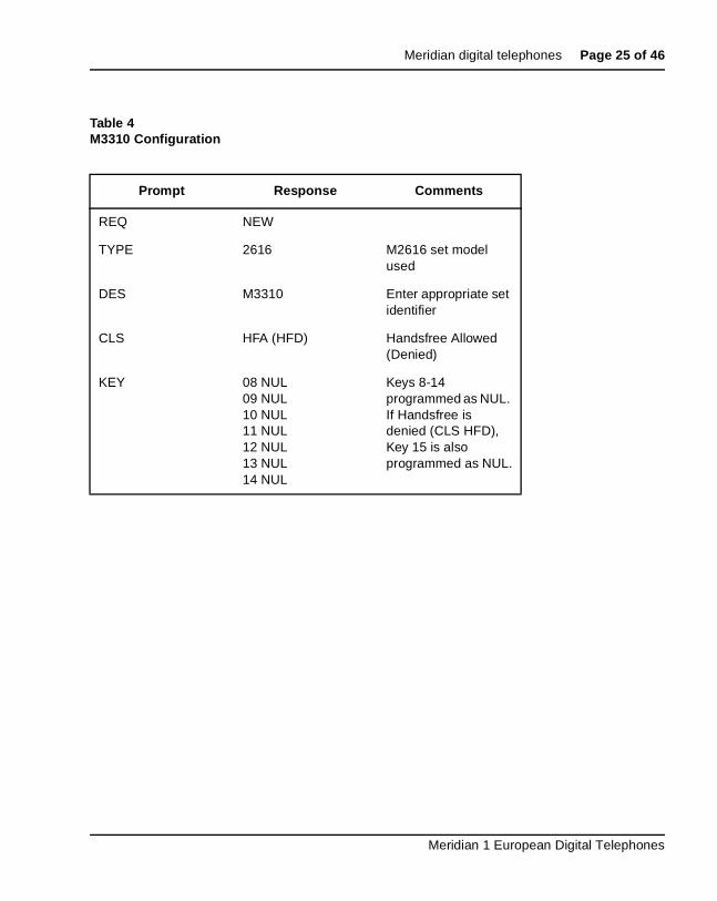
Table 4M3310 Configuration
Prompt Response Comments
REQ NEW
TYPE 2616 M2616 set model used
DES M3310 Enter appropriate set identifier
CLS HFA (HFD) Handsfree Allowed (Denied)
KEY 08 NUL09 NUL10 NUL11 NUL12 NUL13 NUL14 NUL
Keys 8-14 programmed as NUL. If Handsfree is denied (CLS HFD), Key 15 is also programmed as NUL.
Meridian 1 European Digital Telephones
Page 26 of 46 Meridian digital telephones
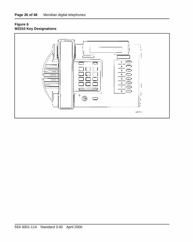
Figure 6M3310 Key Designations
553-3001-114 Standard 3.00 April 2000
Meridian digital telephones Page 27 of 46
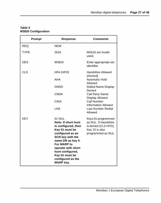
Table 5M3820 Configuration
Prompt Response Comments
REQ NEW
TYPE 2616 M2616 set model used.
DES M3820 Enter appropriate set identifier.
CLS HFA (HFD)
AHA
DNDD
CNDA
CNIA
LNA
Handsfree Allowed (Denied)Automatic Hold AllowedDialed Name Display DeniedCall Party Name Display AllowedCall Number Information AllowedLast Number Redial Allowed
KEY 01 NULNote: If short hunt is configured, then Key 01 must be configured as an SCR key with the same DN as key 0. For MARP to operate with short hunt configured, Key 01 must be configured as the MARP key.
Keys 01 programmed as NUL. If Handsfree is denied (CLS HFD), Key 15 is also programmed as NUL.
Meridian 1 European Digital Telephones
Page 28 of 46 Meridian digital telephones
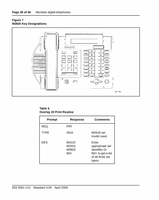
Figure 7M3820 Key Designations
Table 6Overlay 20 Print Routine
Prompt Response Comments
REQ PRT
TYPE 2616 M2616 set model used.
DES M3110M3310M3820M3+
Enter appropriate set identifier Or M3+ to get a list of all three set types.
553-3001-114 Standard 3.00 April 2000
Meridian digital telephones Page 29 of 46
pad,
ber card
the
for :
ns:
ey
InstallationThe Installation procedure for Meridian digital telephones follows:
1 Complete the wiring and cross-connections (loop power) before connecting the telephone to the connecting block.
2 Place the telephone on the desk in the normal operating position.
3 Place the Rls and Hold key caps on their positions just above the dialwith the Hold key closest to the handset.
4 Print the directory number on the designation card. Remove the numlens from its position underneath the handset, insert the designation and snap the lens into place.
5 Print the feature keys on the label strip. Remove the label lens (besidefeature keys), insert the label strip and snap the lens into place.
6 Plug the line cord connector into the connecting block.
7 Perform the self test and acceptance procedures (see procedure 16Meridian Modular telephones in the Telephone and Attendant ConsoleInstallation (553-3001-215).
8 Supply the user with a quick reference card.
Installation of Hardware OptionsThis section describes the procedure for installation of the following optio
1 Power Board on all models.
2 Headset on M3310 and M3820 telephones.
3 Wallmount/Desktop Position change.
For installation of other options (MCA data option, external alerter and kexpansion modules) see the section on Add-on modules for Meridian Modular Telephones (NT2K models) in the Telephone and Attendant Console: Installation (553-3001-215).
Meridian 1 European Digital Telephones
Page 30 of 46 Meridian digital telephones
if
e
der.
tion able
the
wer
B.
n the
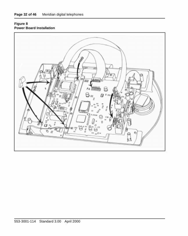
Power Board Installation
To open the Telephone:
1 Place the telephone, upside-down, on a padded, level surface.
2 Using a #1 Phillips screwdriver, remove the two screws holding the footstand (if fitted).
3 Disconnect and remove all cords including the handset and headsetfitted, from the telephone.
4 Use a #1 Phillips screwdriver and remove the four screws holding thbase of the telephone.
To install the Power Board:
1 Remove the cable from the power board including the right angle hea
2 Disconnect the display cable from P4 on the main PCB. Note the orientation of this connector.
3 Place the power board to the left of the main PCB with the widest secof the power board nearest the display. Make sure that the display ccomes over the power board.
4 Clip the power board in place, by inserting the right hand side of theboard under the clip, then push down on the left hand side adjacent toclips provided.
5 Use a #1 Phillips screwdriver and the screw supplied to fasten the poboard to the front cover of the telephone.
6 Remove and discard the two links on J8 on the telephone's main PC
7 Connect the power board cable (B0247405) to J8.
Note the key to prevent misconnection.
8 Connect the cable to the header at H1 on the power board as shown ifigure below).
9 Reconnect the display cable to P4.
Note: Do NOT twist the cable.
553-3001-114 Standard 3.00 April 2000
Meridian digital telephones Page 31 of 46
a nt
rate
f the
hone.
(if
on.
To reassemble the Telephone:
1 Replace the base cover and make sure that the cables lie flat.
2 Insert the four screws to secure the base.
3 Assemble the MCA to the footstand using the two screws provided.
4 Connect the cable to the 8 way jack on the base of the telephone.
5 Reconnect all cords to the telephone.
6 Replace the footstand with the two screws (if previously fitted).
7 Place the power board label on the footstand for tracking purposes.
Headset Installation (M3310 and M3820 only)
Use the following procedure to add a headset to a Meridian telephone:
1 Unplug the line cord from the connecting block.
2 Remove the handset and place the telephone upside down on top iflevel, solid work surface covered with soft material or paper to prevedamage to moveable keys and the telephone face.
3 Remove the 2 screws from the telephone footstand (if fitted) to sepathe footstand from the telephone.
4 Plug the headset TELADAPT connector into the socket on the base otelephone marked with a headset icon.
5 Route the headset cord through the channels at the side of the telep
6 Replace the footstand in the same position and tighten both screws previously fitted).
7 Place the telephone back on the desk in the normal operating positi
8 Plug the line cord connector back into the connecting block.
Meridian 1 European Digital Telephones
Page 32 of 46 Meridian digital telephones
Figure 8Power Board Installation
553-3001-114 Standard 3.00 April 2000
Meridian digital telephones Page 33 of 46
o
one o the
f a nt
rate
loser
on.
as
or all
. om
f a nt
rate
Telephone Positions
Your Meridian telephone can be installed in three different positions - twdesktop positions and a wall mount position. The two desktop positions provide two different angles for the telephone on the desktop. The telephis supplied in the steeper of the two positions. The procedure to change tmore shallow angle is as follows:
1 Unplug the line cord from the connecting block.
2 Remove the handset and place the telephone upside down on top olevel, solid work surface covered with soft material or paper to prevedamage to moveable keys and the telephone face.
3 Remove the 2 screws from the telephone footstand (if fitted) to sepathe footstand from the telephone.
4 Snap the footstand back into place using the alternate slots located cto the back of the set and tighten the screws (if previously fitted).
5 Place the telephone back on the desk in the normal operating positi
6 Plug the line cord connector back into the connecting block.
The procedure to wall mount the telephone by reversing the footstand isfollows:
Note 1: The footstand cannot be reversed when the MCA data optionkey expansion module is equipped so such telephones cannot be wmounted.
Note 2: An additional clip is provided for wall mounting the telephoneThis clip is attached to the switchhook rest to prevent the handset frslipping when mounted on the wall.
1 Unplug the line cord from the connecting block.
2 Remove the handset and place the telephone upside down on top olevel, solid work surface covered with soft material or paper to prevedamage to moveable keys and the telephone face.
3 Remove the 2 screws from the telephone footstand (if fitted) to sepathe footstand from the telephone.
Meridian 1 European Digital Telephones
Page 34 of 46 Meridian digital telephones
he
e and ase
on
4 Remove the wall mount clip located inside the footstand and insert tclip in the switchhook rest using the holes provided.
5 Rotate the footstand 180 degrees, snap the footstand back into plactighten the screws. Note that the footstand must be screwed to the bfor wall mounting.
6 Mount the telephone on the wall using the wall mount holes providedthe bottom of the footstand.
7 Plug the line cord connector back into the connecting block.
553-3001-114 Standard 3.00 April 2000
Meridian digital telephones Page 35 of 46
es.
stry.
SpecificationsThis section lists the specifications required for Meridian digital telephon
Environmental and safety considerationsAll Meridian digital telephones are designed to comply with:
EN 60950:1992 - Safety of Information Technology Equipment includingElectrical Business Equipment.
EN 41003:1993 - Particular Safety Requirements for Equipment to be connected to Telecommunication Network.
Temperature and humidity
Electromagnetic interferenceAll the digital telephones are designed to comply with:
EN 50082-1:1992 - Electromagnetic Compatibility - Generic immunity standard Part 1: Residential, commercial and light industry.
EN 50081-1:1992 - Electromagnetic Compatibility - Generic emissions standard. Generic standard class: Residential, commercial and light indu
Operating state:Temperature range 0° to 50°C (32° to 104°F)
Relative humidity 5% to 95% (noncondensing). At temperaturesabove 34°C (93°F) relative humidity is limited to 53 mbar of water vapor pressure.
Storage: Temperature range –50° to 70°C (–58° to 158°F)
Relative humidity 5% to 95% (noncondensing). At temperaturesabove 34°C (93°F) relative humidity is limited to 53 mbar of water vapor pressure.
Meridian 1 European Digital Telephones
Page 36 of 46 Meridian digital telephones
m),
e
rd
em es to
led
ian
Line engineeringMeridian digital telephones use twisted pair wiring on transmission linesselected by the rules given in Digital Telephone Line Engineering (553-2201-180). The maximum permissible loop length is 3500 ft. (1067 assuming 24 AWG (0.5 mm) standard twisted wire with no bridge taps. A15.5 dB loss at 256 kHz defines the loop length limit. (Longer lengths arpossible, depending on the wire’s gauge and insulation.) Table 7 gives detailed information on loop lengths.
Note: Use only the line cord provided with the telephone. Using a codesigned for another telephone could result in damage to the cord.
Local alerting tonesEach telephone provides four alerting tones and a buzz sound. The systcontrols the ringing cadence by sending tone-ON and tone-OFF messagthe telephone. The alerting tone cadences cannot be changed from the telephone but can be altered for individual terminals by software controladjustments in the system. See X11 Administration (553-3001-311). All other telephone tones, such as dial tone or overflow, are provided by the Merid1 from a Tone and Digit Switch.
Table 7Loop lengths for Meridian digital telephones
QPC578 A and B QPC578 C + NT8D02
PVC insulated cable (polyvinyl chloride)
22 or 24 AWG 100–3000 ft.(30.5–915 m)
0–3500 ft.(0–1067 m)
0–3500 ft.(0–1067 m)
26 AWG 100–2100 ft.(30.5–640 m)
0–2600 ft.(0–945 m)
0–2600 ft.(0–793 m)
Note 1: No bridge taps or loading coils are allowed.
Note 2: Effect of line protector at MDF reduces loop length by 500 ft.
553-3001-114 Standard 3.00 April 2000
Meridian digital telephones Page 37 of 46
ng es a
ion.
op nd
er se
Alerting tone characteristicsThe tone frequency combinations are as follows:
A 500 Hz buzz signal is provided for incoming call notification while the receiver is off-hook.
Power requirementsThe Meridian digital telephones are loop powered. Loop power, originatiin the ISDLC or the DLC, consists of a 30 V dc power source and assum3500 ft. (1219 m) maximum loop length of 24 AWG (0.5 mm) wire and aminimum 15.5 V dc at the telephone terminals.
Note: The loop length limit is defined by a 15.5 dB loss at 256 KHz. Longer lengths can be determined using the wire’s gauge and insulat
Some configurations of telephones and options need more than basic lopower to operate. Table 8 lists the types of Meridian digital telephones ashows when additional power is needed to operate the telephone or its optional hardware. Power Supply Boards come installed in factory-assembled configurations that require additional power.
Note: If a power failure occurs, configurations that require loop powwill continue to work only if the system has battery backup. Only thooptions that require additional power will cease to function.
Tone Frequencies Warble Rate (Hz)1 667 Hz, 500 Hz 5.2
2 667 Hz, 500 Hz 2.6
:
3 1600 Hz, 2000 Hz 5.2
4 1600 Hz, 2000 Hz 2.6
:
3 333 Hz, 250 Hz 5.2
4 333 Hz, 250 Hz 2.6
Meridian 1 European Digital Telephones
Page 38 of 46 Meridian digital telephones
side t r
tom
G
e and
Power supply boardThe power supply option consists of a power supply board that mounts inthe telephone, coupled with an external wall-mount transformer or closepower supply that provides power to the power supply board. The powesupply board receives its power through pins 1 and 6 of the line cord.
The power supply board connects to the telephone through a 14-pin botentry connector.
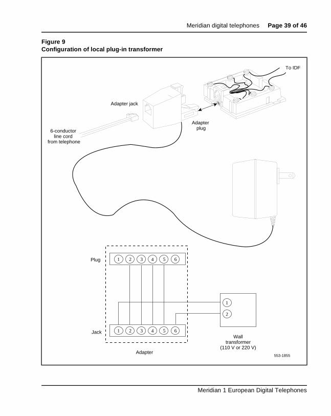
Local plug-in transformerA single winding transformer equipped with a 10 ft. (3 m) cord of 22 AWtwo-conductor stranded and twisted wire with a modular RJ-11 duplex adapter can provide the additional power needed to operate the telephonits options. (See Figure 9).
Table 8Power requirements, Meridian digital telephones
Telephone type Loop powerAdditional power (Power Supply Board)
M3820 Terminal, handsfree, headset, key expansion
MCA, External Alerter Interface
M3310 Terminal, headset, handsfree MCA, External Alerter Interface
M3110 Terminal MCA, External Alerter Interface
CAUTIONDo not plug any equipment other than the terminal into the RJ-11 transformer adapter, as damage to equipment can result.
553-3001-114 Standard 3.00 April 2000
Meridian digital telephones Page 39 of 46
Figure 9Configuration of local plug-in transformer
To IDF
6-conductor line cord
from telephone
Adapter jack
Adapter plug
1 2 3 4 5 6
1 2 3 4 5 6
1
2
Plug
Jack
Adapter553-1855
Walltransformer
(110 V or 220 V)
Meridian 1 European Digital Telephones
Page 40 of 46 Meridian digital telephones
y
n it it.
t. ss. e
o
120 V transformer The following minimum specifications must be met bythis transformer:
240 V transformer The following minimum specifications have to be met bthis transformer:
Note 1: You cannot wall mount the telephone over the wall jack wheusing a transformer because of the size of the RJ-11 adapter. Hangabove or to the side of the jack and run the line and power cords to
Note 2: The above-mentioned transformers can also be used with outlets identified as 110V or 220V.
Closet Power SupplyCloset power can be obtained from an AC transformer for loops of 100 f(30 m) or less, or a DC transformer for loop lengths of 650 ft. (198 m) or leAn equivalent power source can be used but must be UL listed to providisolation of outputs to the terminal. See Figure 10.
Input voltage 120 V ac/60 Hz
No load output voltage 29 V ac maximum
Voltage at rated current 26.7 V ac minimum
Rated load current 700 mA
Input voltage 240 V ac/50 Hz
No load output voltage 29 V ac maximum
Voltage at rated current 26.7 V ac minimum
Rated load current 700 mA
CAUTIONWhen using closet power, do not plug the TELADAPT connector into any equipment other than the Meridian digital telephone, as damage tequipment may result.
553-3001-114 Standard 3.00 April 2000

Meridian digital telephones Page 41 of 46
h te
th
ce f 1
Note 1: All terminals must be isolated from the input winding and eacterminal must be isolated from all other terminal windings. A separawinding is required for each terminal, and grounds must not be connected.
Note 2: The QUT1 closet power supply source is not compatible wiMeridian digital telephones.
The AC source must be rated at 29 V ac, 700 mA isolated. The DC sourmust be rated at 42 V dc, 300 mA isolated, with current limiting output oamp.
Figure 10Closet Power Supply configuration
12
3
45
6
W BL
6-conductorline cord
from telephone
To IDFTip (r)
Ring (g)
Closet Power Supply
(Shumway SBI 221-25 or equivalent)
Connects to an isolated output
553-1856
Meridian 1 European Digital Telephones
Page 42 of 46 Meridian digital telephones
553-3001-114 Standard 3.00 April 2000
Page 43 of 46
44
nd
GlossaryThis section lists, by alphanumeric order, the acronyms, abbreviations, ainitializations used in this guide.
ACDAutomatic Call Distribution
ADOAsynchronous Data Option
COSClass of Service
CCOSControlled Class of Service
CPMCall Progress Monitor
CPNDCalling Party Name Display
DCEData Communications Equipment
DLCDigital Line Card
DNDirectory Number
Meridian 1 European Digital Telephones
Page 44 of 46 Glossary
DSICDigital Set Interface Chip
DTEData Terminal Equipment
EIAElectronic Industries Association
FCCFederal Communications Commission
IDFIntermediate Distribution Frame
ISDLCIntegrated Services Digital Line Card
LCDLiquid Crystal Display
LEDLight Emitting Diode (lamp)
MDFMain Distribution Frame
MCAMeridian Communications Adapter
PCMPulse Code Modulation
TNTerminal Number
553-3001-114 Standard 3.00 April 2000
Page 45 of 46
46
Index
Aactive stateM3820, M3310, M3110, 20alerting tones
M3820, M3310, M3110, 36Asynchronous Data Option. See ADO
(Asynchronous Data Option)
Bbatteries
for headsets, 17Brandline Inserts, 22
Ccables. See wiring and loop lengthscards
DLC (Digital Line Card), 9ISDLC (Integrated Services Digital Line
Card), 9closet power supplies, 38, 40cords
and TELADAPT snap-in connectors, 40See also wiring and loop lengths
custom labeling (logos) with Brandline Inserts, 22
Ddata calls capability
See also ADO (Asynchronous Data Option)data channels, 9dialing
See also Handsfree operationdimensions. See under individual modes of
telephones
DLC (Digital Line Card), 9
Eelectret headsets, 17electromagnetic interference specifications
M3820, M3310, M3110 telephones, 35environmental and safety considerations
M3820, M3310, M3110, 35External Alerter interface, 22
Ffrequencies. See local alerting tones
Gglossary, 43
HHandsfree operation
M3820, M3310, M3110 terminals, 21headsets
electret, 17interfaces, 17
hold stateM3820, M3310, M3110, 20
humidity range requirements. See temperature and humidity ranges for operations
Iidle state
M3820, M3310, M3110 telephones, 20ISDLC (Integrated Services Digital Line Card), 9
Meridian 1 European Digital Telephones
Page 46 of 46 Index
Jjacks
for headsets, 17and TELADAPT snap-in connectors, 40
LLCD indicators
M3820, M3310, M3110, 20See also screens
local alerting tones. See alerting toneslogos with Brandline Inserts, 22loop lengths. See wiring and loop lengths
MM3820, M3310, M3110
environmental and safety considerations, 35hardware features and options, 21line engineering, 36local alerting tones, 36
M3820, M3310, M3110 telephonespower requirements
M3820, M3310, M3110 tele-phones, 37
Meridian 1 telephonesrelated documentation, 7
Meridian digital telephone headset interface, 17Meridian digital telephones M3820, M3310,
M3110, 20functions, connections, and interfaces, 9
Meridna digital telephones M3820, M3310, M3110fixed keys, 18
message waiting feature, 20microphone
on M3820, M3310, M3110 telephones, 21
PPeripheral Equipment shelf, 9Phase II/III QSU1 telephones. See SL-1 telephonespower requirements
for headsets, 17, 37
553-3001-114 Standard 3.00 April 2000
for recording devices, 17See also batteries; transformers
programmable keysM3820, M3310, M3110, 20M3820, M3310, M3110 telephones, 21See also softkeys
PVC cable, 36
Rremote ringers, 22ringing state
on M3820, M3310, M3110, 20
Ssafety considerations. See environmental and safety
considerationssoftkeys
See also programmable keys
TTELADAPT snap-in connectors, 40telephones. See Meridian 1 telephonestemperature and humidity ranges for operations
Meridian digital telephones, 35tones. See alerting tones; volume controltransformers
for headsets (AC), 17local plug-in, 38See also power requirements
Vvoice channels/ports, 9volume control
M3820, M3310, M3110, 20
Wwarble rates. See local alerting toneswiring and loop lengths
M3820, M3310, M3110, 40M3820, M3310, M3110 telephones, 36, 37

Family Product Manual Contacts Copyright FCC notice Trademarks Document number Product release Document release Date Publish
Meridian 1
Meridian 1 European Digital Telephones
Copyright © 1997– 2000 Nortel NetworksAll Rights ReservedInformation is subject to change without notice. Nortel Networks reserves the right to make changes in design or components as progress in engineering and manufacturing may warrant. This equipment has been tested and found to comply with the limits for a Class A digital device pursuant to Part 15 of the FCC rules, and the radio interference regulations of Industry Canada. These limits are designed to provide reasonable protection against harmful interference when the equipment is operated in a commercial environment. This equipment generates, uses and can radiate radio frequency energy, and if not installed and used in accordance with the instruction manual, may cause harmful interference to radio communications. Operation of this equipment in a residential area is likely to cause harmful interference in which case the user will be required to correct the interference at their own expense.SL-1 and Meridian 1 are trademarks of Nortel Networks.Publication number: 553-3001-114Document release: Standard 3.00Date: April 2000Printed in Canada